Abstract— This paper presents an investigation and evaluation of the performance of the Permanent Magnet synchronous Motor drive controlled by conventional PI (Proportional Integral), SUI PI (Simplified Universal Intelligent PI) controller, ANN (Artificial Neural Network) and Fuzzy Logic Controllers. A detailed study and comparisons between these different kinds of controllers were presented on the simulation results. Keywords— Permanent magnet synchronous motor, Conventional PI controller, SUI PI controller, ANN controller and Fuzzy Logic Controller. NOMECLATURE I. INTRODUCTION ndustry automation is mainly developed around motion control systems in which controlled electric motors play a crucial role as heart of the system. Therefore, the high performance motor control systems contribute, to a great extent, to the desirable performance of automated manufacturing sector by enhancing the production rate and the quality of products. In fact the performance of modern automated systems, defined in terms of swiftness, accuracy, smoothness and efficiency, mainly depends to the motor control strategies. The advancement of control theories, power electronics and microelectronics in connection with new motor designs and materials have contributed largely to the filed of electric motor control for high performance systems [1]. Sensorless control of PMSM has been going on simultaneously. In later years Permanent Magnet Synchronous Machines has been increasingly popular as the cost of permanent magnets is decreasing and the quality of the magnets improves. The activity on sensorless control of PMSM has increased as the application ranges of the PMSM are expanding and many researchers have carried out many developments on the sensorless control of PMSM. This paper presents different kinds of controllers were applied on the Permanent Magnet Synchronous motor like conventional PI (Proportional Integral) control, Simplified Universal Intelligent PI and the Artificial Neural Network which is considered a promising alternative to conventional control techniques [2]. The most common choice for the speed controller is the so called PI compensator since it has a simple structure and can offer a satisfactory performance over a wide range of operation. The main problem of that simple controller is the correct choice of the PI gains and the fact that by using fixed gains, the controller may not provide the required control performance, when there are variations in the plant parameters and operating conditions. Therefore, a tuning process must be performed to insure that the controller can deal with the variations in the plant. Artificial Intelligence (AI) techniques such as neural networks and fuzzy logic are gaining increased interest nowadays. II. PMSM MODEL The stators of the PMSM and wound rotor synchronous motor are similar. In addition there is no difference between the back EMF produced by a permanent magnet and that produced by an excited coil. Hence the mathematical model of a PMSM is similar to that of the wound rotor SM [3]. The Volt-Ampere stator d, q equations in the rotor reference frame of the PMSM are:- q r d d d p p RI V λ ϖ λ - = (1) d r q q q p p RI V λ ϖ λ - + = (2) Where, df d d d I L λ λ = , q q q I L = λ dt d p = (3) High Performance Control of Sensorless Permanent Magnet Synchronous Motor Mohamed I. Abu El- Sebah and Ghada A. Abdel Aziz, q d I I , q d - Stator currents q d V V , q d - Stator voltages r ϖ Electrical speed ( s rad ) r θ Electrical position ( rad ) R Stator Resistance ( Ω ) T K Motor torque constant F Fractional Coefficient L T Load torque ( m N . ) J Rotor inertia ( 2 . m Kg ) P Number of Poles K Modified controller gain C The controller output m C The modified controller output I

Welcome message from author
This document is posted to help you gain knowledge. Please leave a comment to let me know what you think about it! Share it to your friends and learn new things together.
Transcript
Abstract— This paper presents an investigation and
evaluation of the performance of the Permanent Magnet synchronous Motor drive controlled by conventional PI (Proportional Integral), SUI PI (Simplified Universal Intelligent PI) controller, ANN (Artificial Neural Network) and Fuzzy Logic Controllers. A detailed study and comparisons between these different kinds of controllers were presented on the simulation results.
Keywords— Permanent magnet synchronous motor,
Conventional PI controller, SUI PI controller, ANN controller and Fuzzy Logic Controller.
NOMECLATURE
I. INTRODUCTION
ndustry automation is mainly developed around motion control systems in which controlled electric motors play a
crucial role as heart of the system. Therefore, the high performance motor control systems contribute, to a great extent, to the desirable performance of automated manufacturing sector by enhancing the production rate and the quality of products. In fact the performance of modern automated systems, defined in terms of swiftness, accuracy, smoothness and efficiency, mainly depends to the motor control strategies. The advancement of control theories, power electronics and microelectronics in connection with new motor designs and materials have contributed largely to the filed of electric motor control for high performance systems [1].
Sensorless control of PMSM has been going on simultaneously. In later years Permanent Magnet Synchronous Machines has been increasingly popular as the cost of permanent magnets is decreasing and the quality of the magnets improves. The activity on sensorless control of PMSM has increased as the application ranges of the PMSM are expanding and many researchers have carried out many developments on the sensorless control of PMSM. This paper presents different kinds of controllers were applied on the Permanent Magnet Synchronous motor like conventional PI (Proportional Integral) control, Simplified Universal Intelligent PI and the Artificial Neural Network which is considered a promising alternative to conventional control techniques [2]. The most common choice for the speed controller is the so called PI compensator since it has a simple structure and can offer a satisfactory performance over a wide range of operation. The main problem of that simple controller is the correct choice of the PI gains and the fact that by using fixed gains, the controller may not provide the required control performance, when there are variations in the plant parameters and operating conditions. Therefore, a tuning process must be performed to insure that the controller can deal with the variations in the plant. Artificial Intelligence (AI) techniques such as neural networks and fuzzy logic are gaining increased interest nowadays.
II. PMSM MODEL
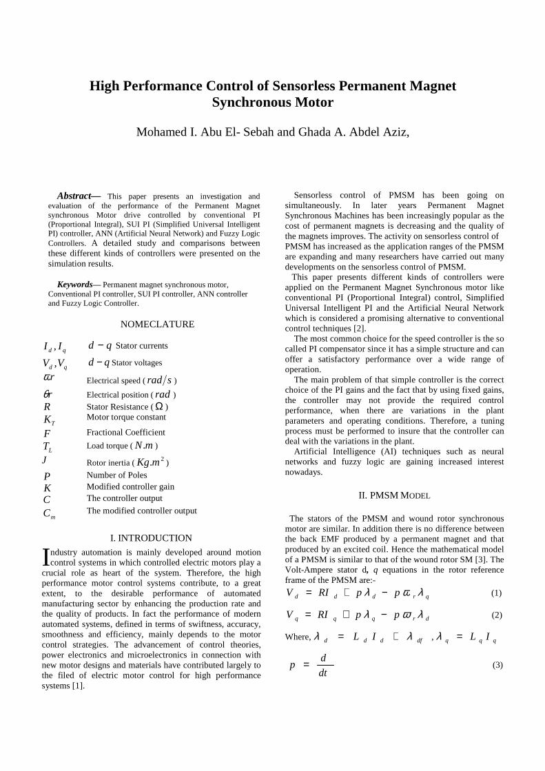
The stators of the PMSM and wound rotor synchronous motor are similar. In addition there is no difference between the back EMF produced by a permanent magnet and that produced by an excited coil. Hence the mathematical model of a PMSM is similar to that of the wound rotor SM [3]. The Volt-Ampere stator d, q equations in the rotor reference frame of the PMSM are:-
qrddd ppRIV λωλ −+= (1)
drqqq ppRIV λωλ −+= (2)
Where, dfddd IL λλ += , qqq IL=λ
dt
dp = (3)
High Performance Control of Sensorless Permanent Magnet Synchronous Motor
Mohamed I. Abu El- Sebah and Ghada A. Abdel Aziz,
qd II , qd − Stator currents
qd VV , qd − Stator voltages
rω Electrical speed ( srad )
rθ Electrical position (rad )
R Stator Resistance (Ω )
TK Motor torque constant
F Fractional Coefficient
LT Load torque ( mN. )
J Rotor inertia ( 2.mKg )
P Number of Poles
K Modified controller gain
C The controller output
mC The modified controller output
I
The electro-magnetic torque:-
(4)
For constant flux operation when dI equals zero, the
electric torque
[ ] qTqaf IKIPTe == λ2
3 (5)
Note that this torque equation for the PMSM resembles that of the regular dc machine and hence provides ease of control. The torque balanced equation is:-
Lrre TFJpT ++= ωω (6)
Equations (1) to (4) can be represented in state space
form:
[ ] dqqrddd LILpRIVpI /ω+−= (7)
[ ] qafrddrqqq LpILpRIVpI /λωω −+−= (8)
[ ] JTFTp Lrer /−−= ωω (9)
The rotor position rθ is state space derivative form is:-
rrp ωθ = (10)
Fig. 1 Analytical model of PMSM
III. SPEED CONTROLLERS
A. Conventional PI Controller
The PI speed controller is a conventional speed controller which is very widely used. It is very easy to model and it can also be easily implemented in the closed loop operation of the drive system. It consists of two control parameters, namely, the proportional and the integral gains. By properly tuning these parameters the desired level of performance can be achieved. The block diagram of the PI speed controller is
developed in SIMULINK. In the PI speed controller, the motor speed is compared with the reference speed. The ideal PID controller shown in Fig. 2 is given by:-
]1
1[)( sTsT
KsG di
cc ++= (11)
Fig. 2 Ideal PID controller
The PID controller consists of three terms:- The first term controller
Cp KK = (Proportional gain) (12)
i
CI T
KK = (Integral gain) (13)
dCd TKK ∗= (Derivative gain) (14)
By the trial and error method we can put values for both pK
and IK until we have a good performance for the PMSM
speed characteristics.
B. SUI PI Controller
The PID controller consists of three terms [4]:-
The first term controller: errorKP P ∗= (15)
The second term controller: ∫∗= dterrorKI I . (16)
The third term controller: dt
derrorKD d ∗= (17)
The following values can then be substituted into the PID controller equation:-
( )errorABSK P = (18)
( )∫= dterrorABSK I . (19)
=dt
derrorABSK d (20)
Selecting the controller constants from the above explanation leads to a simple design algorithm and simplified adaptive weighting for the three terms. The proposed intelligent PID controller is constructed by using the multi degree of freedom controller (MDOF) concept [5], [6]. Applying the intelligent PID controller eliminates the need to know the system steady state gain.
)1(1
*** errorK
CerrorKCCm −+= (21)
K
C
KKerrorCCm +−= )
1(** (22)
[ ]dqqdqaf IILLIPTe )(23 −+= λ
For 1ffK KerrorCCm **= (23)
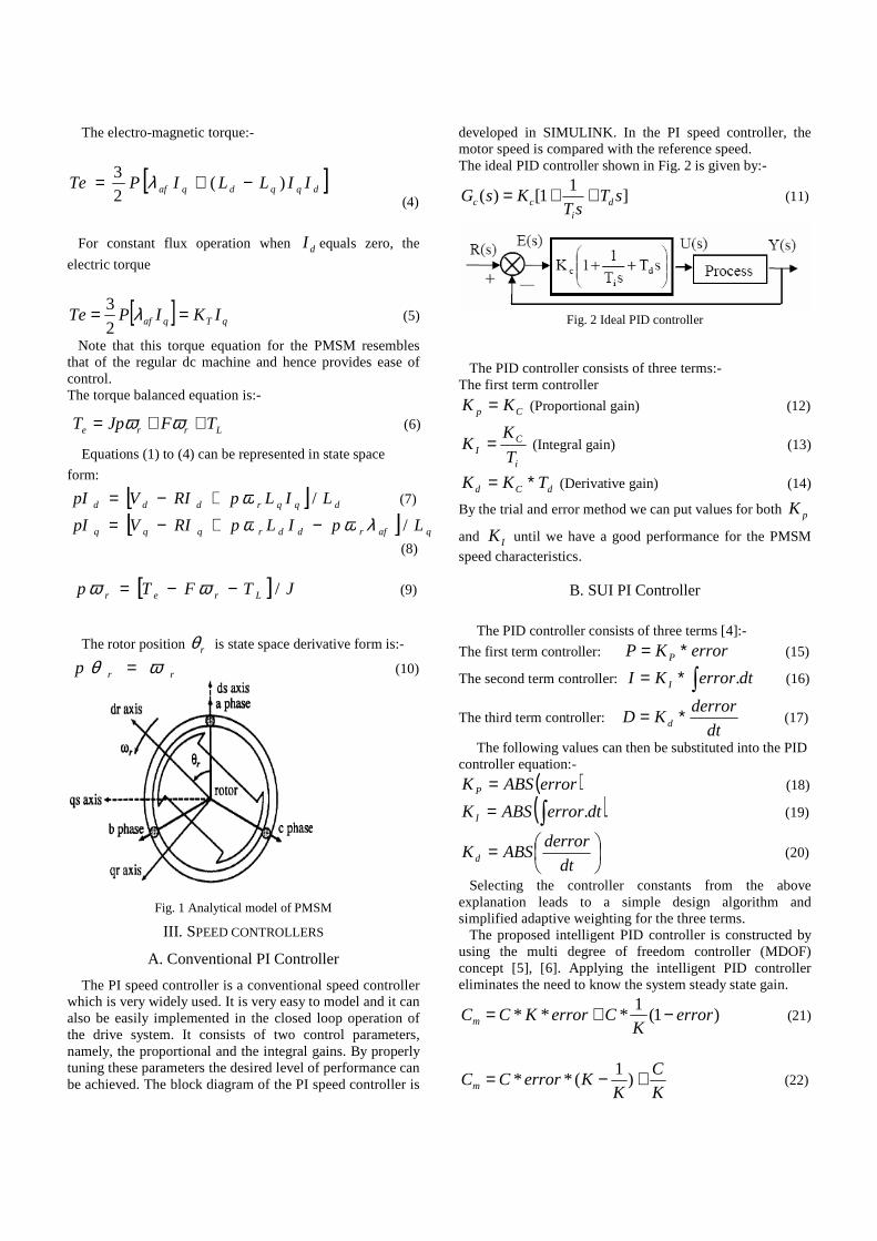
The proposed SUI PI controller is a classical PI with a universal PID constant, so no specific design is needed and therefore there is no need for a system model. The SUI PID
controller constants PK and IK are the absolute values of
errors and integration of errors as shown in Fig.3.
Fig.3 SUI PI controller
C. ANN Controller
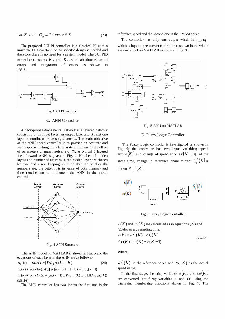
A back-propagations neural network is a layered network consisting of an input layer, an output layer and at least one layer of nonlinear processing elements. The main objective of the ANN speed controller is to provide an accurate and fast response making the whole system immune to the effect of parameters changes, noise, etc [7]. A typical 3 layered feed forward ANN is given in Fig. 4. Number of hidden layers and number of neurons in the hidden layer are chosen by trial and error, keeping in mind that the smaller the numbers are, the better it is in terms of both memory and time requirement to implement the ANN in the motor control.
Fig. 4 ANN Structure The ANN model on MATLAB is shown in Fig. 5 and the equations of each layer in the ANN are as follows:-
))(()( 111,11 bkpIWpurelinka += (24)
))()()1(()(
))1()]1();([()(
22,3311,333,33
22,2111,22
kaLWbkaIWkaLWpurelinka
kpIWkpkpIWpurelinka
+++−=−+−=
(25-26) The ANN controller has two inputs the first one is the
reference speed and the second one is the PMSM speed.
The controller has only one output which is refiq _
which is input to the current controller as shown in the whole system model on MATLAB as shown in Fig. 9.
Fig. 5 ANN on MATLAB
D. Fuzzy Logic Controller
The Fuzzy Logic controller is investigated as shown in Fig. 6; the controller has two input variables; speed
error ( )Ke and change of speed error ( )Kce [8]. At the
same time, change in reference phase current ( )K∗qi is
output ( )K∗∆ qi .
Fig. 6 Fuzzy Logic Controller
)(Ke and )(Kce are calculated as in equations (27) and
(28)for every sampling time:
)1()()(
)()()(
−−=−= ∗
KeKeKCe
KKke rϖϖ (27-28)
Where,
)(K∗ϖ is the reference speed and )(Krω is the actual
speed value.
In the first stage, the crisp variables ( )Ke and ( )Kce
are converted into fuzzy variables e and ce using the triangular membership functions shown in Fig. 7. The
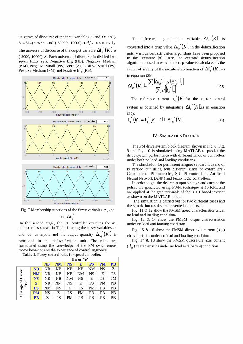
universes of discourse of the input variables e and ce are (-
314,314) srad and (-50000, 10000) srad respectively.
The universe of discourse of the output variable ( )K∗∆ qi is
(-2000, 10000) A. Each universe of discourse is divided into seven fuzzy sets: Negative Big (NB), Negative Medium (NM), Negative Small (NS), Zero (Z), Positive Small (PS), Positive Medium (PM) and Positive Big (PB).
Fig. 7 Membership functions of the fuzzy variables e , ce
and ∗∆ qi
In the second stage, the FL controller executes the 49 control rules shown in Table 1 taking the fuzzy variables e
and ce as inputs and the output quantity ( )Kiq∗∆ is
processed in the defuzzification unit. The rules are formulated using the knowledge of the PM synchronous motor behavior and the experience of control engineers. Table 1. Fuzzy control rules for speed controller.
Error “e” NB NM NS Z PS PM PB
NB NB NB NB NB NM NS Z NM NB NB NB NM NS Z PS NS NB NB NM NS Z PS PM Z NB NM NS Z PS PM PB PS NM NS Z PS PM PB PB PM NS Z PS PM PB PB PB
Cha
nge
of E
rror
“c
e”
PB Z PS PM PB PB PB PB
The inference engine output variable ( )Kiq∗∆ is
converted into a crisp value ( )Kiq∗∆ in the defuzzification
unit. Various defuzzification algorithms have been proposed in the literature [8]. Here, the centroid defuzzification algorithm is used in which the crisp value is calculated as the
center of gravity of the membership function of ( )Kiq∗∆ as
in equation (29):
( ) ( ) ( )[ ]( )[ ]∑
∑∗
∗∗∗ ∆∆
=∆iq
iqiq
qi
iiKi
µµ
(29)
The reference current ( )K∗qi for the vector control
system is obtained by integrating ( )Kiq∗∆ as in equation
(30):
( ) ( ) ( )KKK ∗∗∗ ∆+−= qqq i1ii (30)
IV. SIMULATION RESULTS
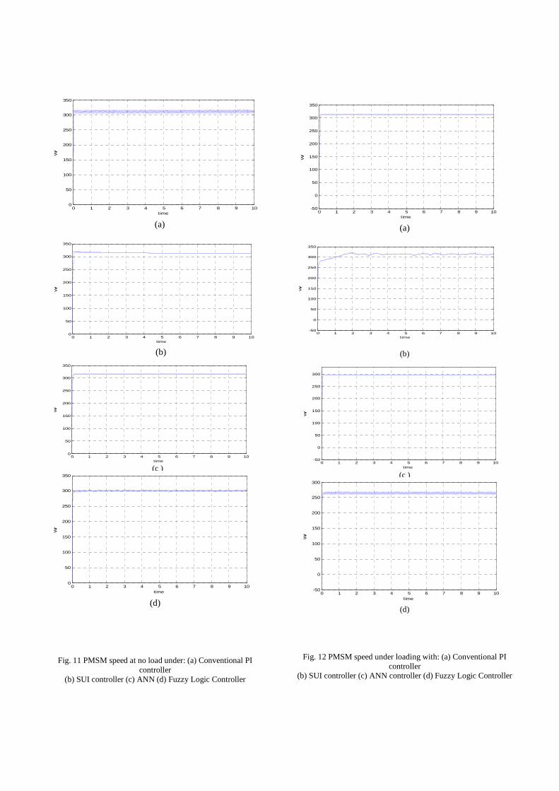
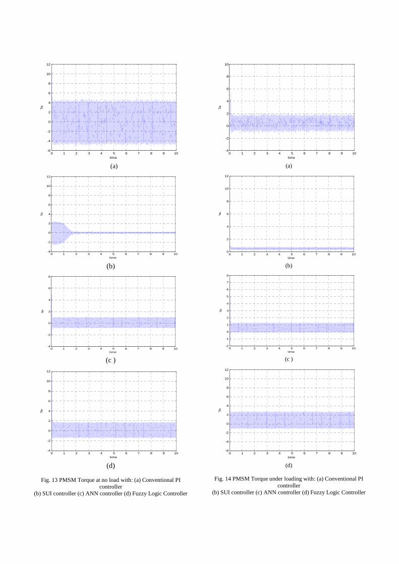
The PM drive system block diagram shown in Fig. 8, Fig. 9 and Fig. 10 is simulated using MATLAB to predict the drive system performance with different kinds of controllers under both no load and loading conditions. The simulation for permanent magnet synchronous motor is carried out using four different kinds of controllers:- Conventional PI controller, SUI PI controller , Artificial Neural Network (ANN) and Fuzzy logic controllers. In order to get the desired output voltage and current the pulses are generated using PWM technique at 10 KHz and are applied at the gate terminals of the IGBT based inverter as shown on the MATLAB model. The simulation is carried out for two different cases and the simulation results are presented as follows:- Fig. 11 & 12 show the PMSM speed characteristics under no load and loading condition. Fig. 13 & 14 show the PMSM torque characteristics under no load and loading condition.
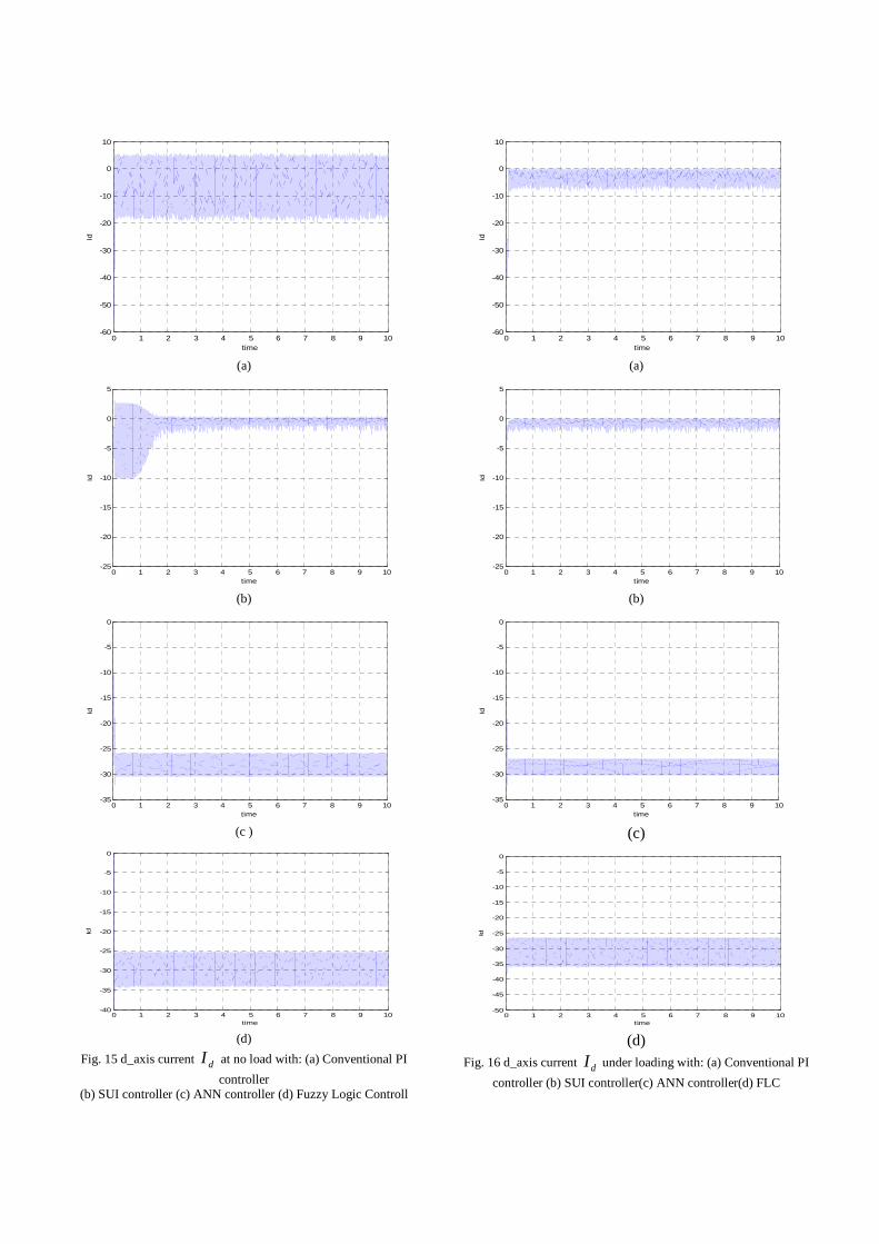
Fig. 15 & 16 show the PMSM direct axis current ( dI )
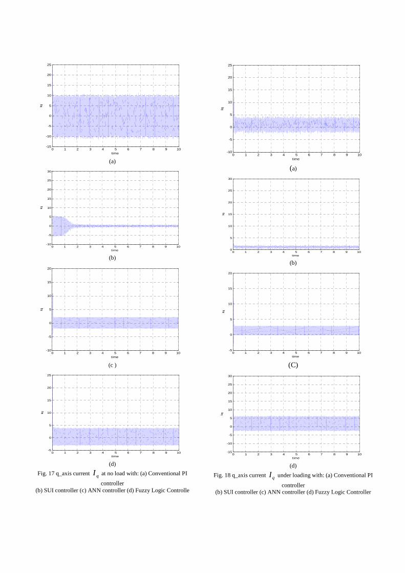
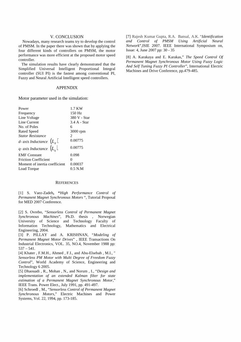
characteristics under no load and loading condition. Fig. 17 & 18 show the PMSM quadrature axis current
( qI ) characteristics under no load and loading condition.
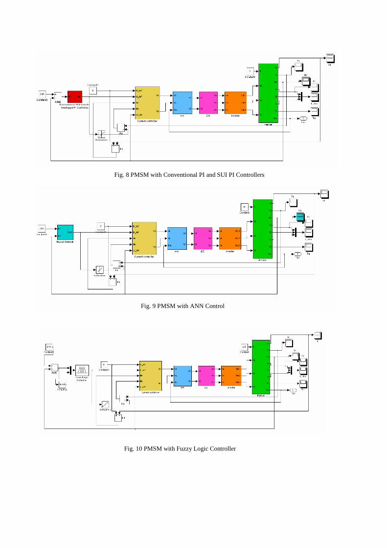
Fig. 8 PMSM with Conventional PI and SUI PI Controllers
Fig. 9 PMSM with ANN Control
Fig. 10 PMSM with Fuzzy Logic Controller
(a)
(b)
0 1 2 3 4 5 6 7 8 9 100
50
100
150
200
250
300
350
time
Wr
0 1 2 3 4 5 6 7 8 9 100
50
100
150
200
250
300
350
time
Wr
(d)
Fig. 11 PMSM speed at no load under: (a) Conventional PI controller
(b) SUI controller (c) ANN (d) Fuzzy Logic Controller
(a)
(b)
0 1 2 3 4 5 6 7 8 9 10-50
0
50
100
150
200
250
300
time
Wr
0 1 2 3 4 5 6 7 8 9 10-50
0
50
100
150
200
250
300
time
Wr
(d)
Fig. 12 PMSM speed under loading with: (a) Conventional PI controller
(b) SUI controller (c) ANN controller (d) Fuzzy Logic Controller
0 1 2 3 4 5 6 7 8 9 100
50
100
150
200
250
300
350
time
Wr
0 1 2 3 4 5 6 7 8 9 100
50
100
150
200
250
300
350
time
Wr
0 1 2 3 4 5 6 7 8 9 10-50
0
50
100
150
200
250
300
350
time
Wr
(c ) (c )
0 1 2 3 4 5 6 7 8 9 10-50
0
50
100
150
200
250
300
350
time
Wr
0 1 2 3 4 5 6 7 8 9 10-6
-4
-2
0
2
4
6
8
10
12
time
Te
(a)
0 1 2 3 4 5 6 7 8 9 10-4
-2
0
2
4
6
8
10
12
time
Te
(b)
0 1 2 3 4 5 6 7 8 9 10-4
-2
0
2
4
6
8
time
Te
(c )
0 1 2 3 4 5 6 7 8 9 10-4
-2
0
2
4
6
8
10
12
time
Te
(d)
Fig. 13 PMSM Torque at no load with: (a) Conventional PI
controller (b) SUI controller (c) ANN controller (d) Fuzzy Logic Controller
0 1 2 3 4 5 6 7 8 9 10-4
-2
0
2
4
6
8
10
time
Te
(a)
0 1 2 3 4 5 6 7 8 9 100
2
4
6
8
10
12
time
Te
(b)
0 1 2 3 4 5 6 7 8 9 10-2
-1
0
1
2
3
4
5
6
7
8
time
Te
(c )
0 1 2 3 4 5 6 7 8 9 10-6
-4
-2
0
2
4
6
8
10
12
time
Te
(d)
Fig. 14 PMSM Torque under loading with: (a) Conventional PI
controller (b) SUI controller (c) ANN controller (d) Fuzzy Logic Controller
0 1 2 3 4 5 6 7 8 9 10-60
-50
-40
-30
-20
-10
0
10
time
Id
(a)
0 1 2 3 4 5 6 7 8 9 10-25
-20
-15
-10
-5
0
5
time
Id
(b)
0 1 2 3 4 5 6 7 8 9 10-35
-30
-25
-20
-15
-10
-5
0
time
Id
(c )
0 1 2 3 4 5 6 7 8 9 10-40
-35
-30
-25
-20
-15
-10
-5
0
time
Id
(d)
Fig. 15 d_axis current dI at no load with: (a) Conventional PI
controller (b) SUI controller (c) ANN controller (d) Fuzzy Logic Controll
0 1 2 3 4 5 6 7 8 9 10-60
-50
-40
-30
-20
-10
0
10
time
Id
(a)
0 1 2 3 4 5 6 7 8 9 10-25
-20
-15
-10
-5
0
5
time
Id
(b)
0 1 2 3 4 5 6 7 8 9 10-35
-30
-25
-20
-15
-10
-5
0
time
Id
(c)
0 1 2 3 4 5 6 7 8 9 10-50
-45
-40
-35
-30
-25
-20
-15
-10
-5
0
time
Id
(d)
Fig. 16 d_axis current dI under loading with: (a) Conventional PI
controller (b) SUI controller(c) ANN controller(d) FLC
0 1 2 3 4 5 6 7 8 9 10-15
-10
-5
0
5
10
15
20
25
time
Iq
(a)
0 1 2 3 4 5 6 7 8 9 10-10
-5
0
5
10
15
20
25
30
time
Iq
(b)
0 1 2 3 4 5 6 7 8 9 10-10
-5
0
5
10
15
20
time
Iq
(c )
0 1 2 3 4 5 6 7 8 9 10-5
0
5
10
15
20
25
time
Iq
(d)
Fig. 17 q_axis current qI at no load with: (a) Conventional PI
controller (b) SUI controller (c) ANN controller (d) Fuzzy Logic Controlle
0 1 2 3 4 5 6 7 8 9 10-10
-5
0
5
10
15
20
25
time
Iq
(a)
0 1 2 3 4 5 6 7 8 9 100
5
10
15
20
25
30
time
Iq
(b)
0 1 2 3 4 5 6 7 8 9 10-5
0
5
10
15
20
time
Iq
(C)
0 1 2 3 4 5 6 7 8 9 10-15
-10
-5
0
5
10
15
20
25
30
time
Iq
(d)
Fig. 18 q_axis current qI under loading with: (a) Conventional PI
controller (b) SUI controller (c) ANN controller (d) Fuzzy Logic Controller
V. CONCLUSION Nowadays, many research teams try to develop the control of PMSM. In the paper there was shown that by applying the four different kinds of controllers on PMSM, the motor performance was more efficient at the proposed motor speed controller. The simulation results have clearly demonstrated that the Simplified Universal Intelligent Proportional Integral controller (SUI PI) is the fastest among conventional PI, Fuzzy and Neural Artificial Intelligent speed controllers.
APPENDIX
Motor parameter used in the simulation:
Power 1.7 KW Frequency 150 Hz Line Voltage 380 V - Star Line Current 3.4 A - Star No. of Poles 6 Rated Speed 3000 rpm Stator Resistance 2
d- axis Inductance ( )dL 0.00775
q- axis Inductance ( )qL 0.00775
EMF Constant 0.098 Friction Coefficient 0 Moment of inertia coefficient 0.00037 Load Torque 0.5 N.M
REFERENCES
[1] S. Vaez-Zadeh, “High Performance Control of Permanent Magnet Synchronous Motors “, Tutorial Proposal for MED 2007 Conference.
[2] S. Ovrebo, “Sensorless Control of Permanent Magnet Synchronous Machines”, Ph.D. thesis , Norwegian University of Science and Technology Faculty of Information Technology, Mathematics and Electrical Engineering, 2004. [3] P. PILLAY and A. KRISHNAN, “Modeling of Permanent Magnet Motor Drives” , IEEE Transactions On Industrial Electronics, VOL. 35, NO.4, November 1988 pp: 537 – 541. [4] Khater , F.M.H., Ahmed , F.I., and Abu-Elsebah , M.I., " Sensorless PM Motor with Multi Degree of Freedom Fuzzy Control”, World Academy of Science, Engineering and Technology 6 2005. [5] Dhaouadi , R., Mohan , N., and Norum , I., “Design and implementation of an extended Kalman filter for state estimation of a Permanent Magnet Synchronous Motor,” IEEE Trans. Power Elect., July 1991, pp. 491-497. [6] Schroedl , M., “Sensorless Control of Permanent Magnet Synchronous Motors,” Electric Machines and Power Systems, Vol. 22, 1994, pp. 173-185.
[7] Rajesh Kumar Gupta, R.A. Bansal, A.K. “Identification and Control of PMSM Using Artificial Neural Network”,ISIE 2007. IEEE International Symposium on, Issue: 4, June 2007 pp: 30 - 35
[8] A. Karakaya and E. Karakas,” The Speed Control Of Permanent Magnet Synchronous Motor Using Fuzzy Logic And Self Tuning Fuzzy PI Controller”, International Electric Machines and Drive Conference, pp.479-485.
Related Documents