HEATING SYSTEM 101 HEATING SYSTEM 101

Welcome message from author
This document is posted to help you gain knowledge. Please leave a comment to let me know what you think about it! Share it to your friends and learn new things together.
Transcript

HEATING SYSTEM 101HEATING SYSTEM 101

Objective • Provide non‐heating personnel with a basicunderstandingg of heatingg syystems:
– Types of Heating Systems – Identification of Components and Basic Operation Identification of Components and Basic Operation – When do I Replace? – Specifications for Installation – Installation – Venting – Health and Safety Concernsand Saf ConcernsHealth ety – Partnerships

Fuels • Fossil
– #2 Fuel Oil–home heating interior tank K t i t k ( bil h )– Kerosene–exterior tank (mobile homes)
• Gas – Natural GasNatural Gas – Propane
• Solid Fuels – Wood – Pellets
•• ElectricElectric

Types of Equipment • Oil Fired
– Power Gun Burner (Mid Efficiency) •• Gas/Propane Fired Gas/Propane Fired
– Atmospheric‐Cat I (Mid Efficiency) – Induced Draft‐Cat III (Slightly Higher Efficiency) – Condensing‐Cat IV (High Efficiency)
Forced Air Forced Air Hydronic (Boiler) Hydronic (Boiler) High boy Fin Baseboard Low Boy Radiators O tOctopus Counter‐flow

Gas Forced Air High Boy


Oil Fired Boiler
Mobile Home‐Counterflow


Heating System Components • Burner • Fire box • Heat Exchanger • Distribution System
– Forced Air • Blower, Plenums‐hot and cold air, Ductwork
– Boiler • Circulator Pump, Piping, Radiators or Baseboard
• Basic Controls • Saffety switchhes

Components of a Gas Fired Forced Air SystemForced Air System
Heat Exchanger
Fire box
Burner
Blower

Components of a Boiler

Whhen ddo I Repllace??
• Price of repair exceeds value of furnace
• Major health and safety concernMajor health and safety concern – Cracked Heat Exchanger

What is aWhat is a
Cracked Heat Exchanger?


–
Testing for a Cracked Heat Exchanger • Visual Inspection of Heat Exchanger
– From the TopFrom the Top • Through humidifier • Remove Plenum
– From the Bottom • Remove blower and inspect through blower compartment
• Smoke Bomb
• Oil of Wintergreen

Additional Heat Exchanger Inspections • Performed when the blower energizes
– Draft • Should stay consistent, before blower and after blowerenergizes
– O / CO O2 / CO2 • Increase in O2 (or decrease in CO2) after blowerenergizes indicates additional air is entering thecombustion processcombustion process
– Visual flame examination • Should not waver when blower energizes

Visual Inspection with Light

Visual Inspection with Mirror

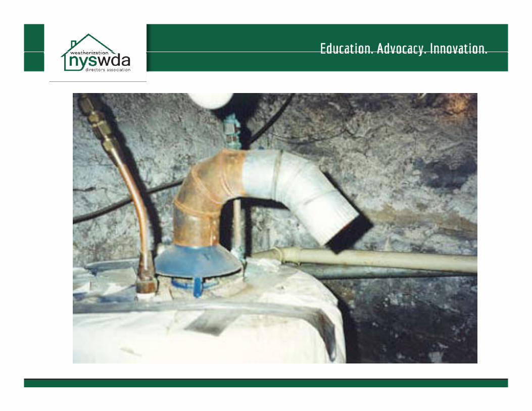
Vents and Chimneys

Venting – Category I • Negative pressure, nonnon‐Negative pressure, condensing
• Materials – MMasonry ‐ solid f l lid fuels, oilil, **gas
• Outside masonry chimneys mayneed to be lined to accommodate repplacement ggas heating appliances
– B‐vent – gas • Approved for installation withinthhe envellope onlly
– L‐vent ‐ oil – All fuel ‐ solid fuel, oil, gas
• Ensure termination is permanufacturer specification

Venting ‐ Category IV
• Positive pressure, condensing
• PVC vented directly outdoorsoutdoors – Proper support and
pitch are essential
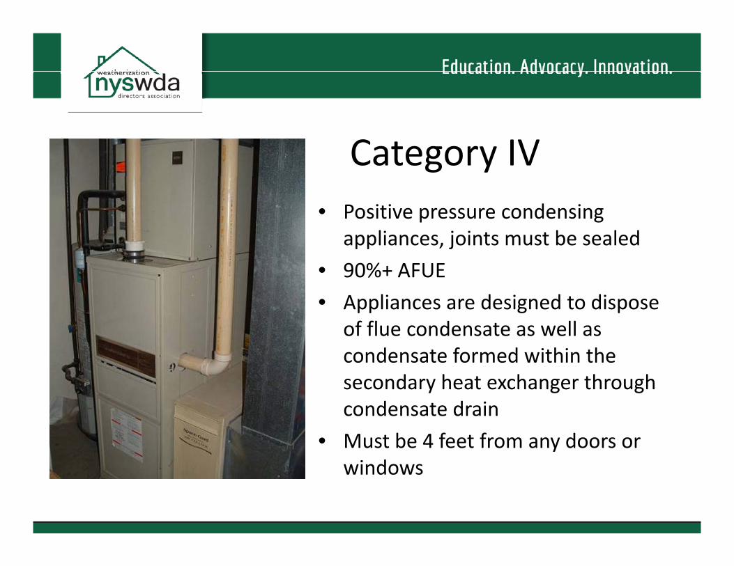
Category IV • Positive pressure condensing
appliances,, j joints must be sealed pp
• 90%+ AFUE
• Appliances are designed to dispose of flue condensate as well as condensate formed within the secondaryy heat exchangger througgh condensate drain
• Must be 4 feet from any doors or wi dindows
–
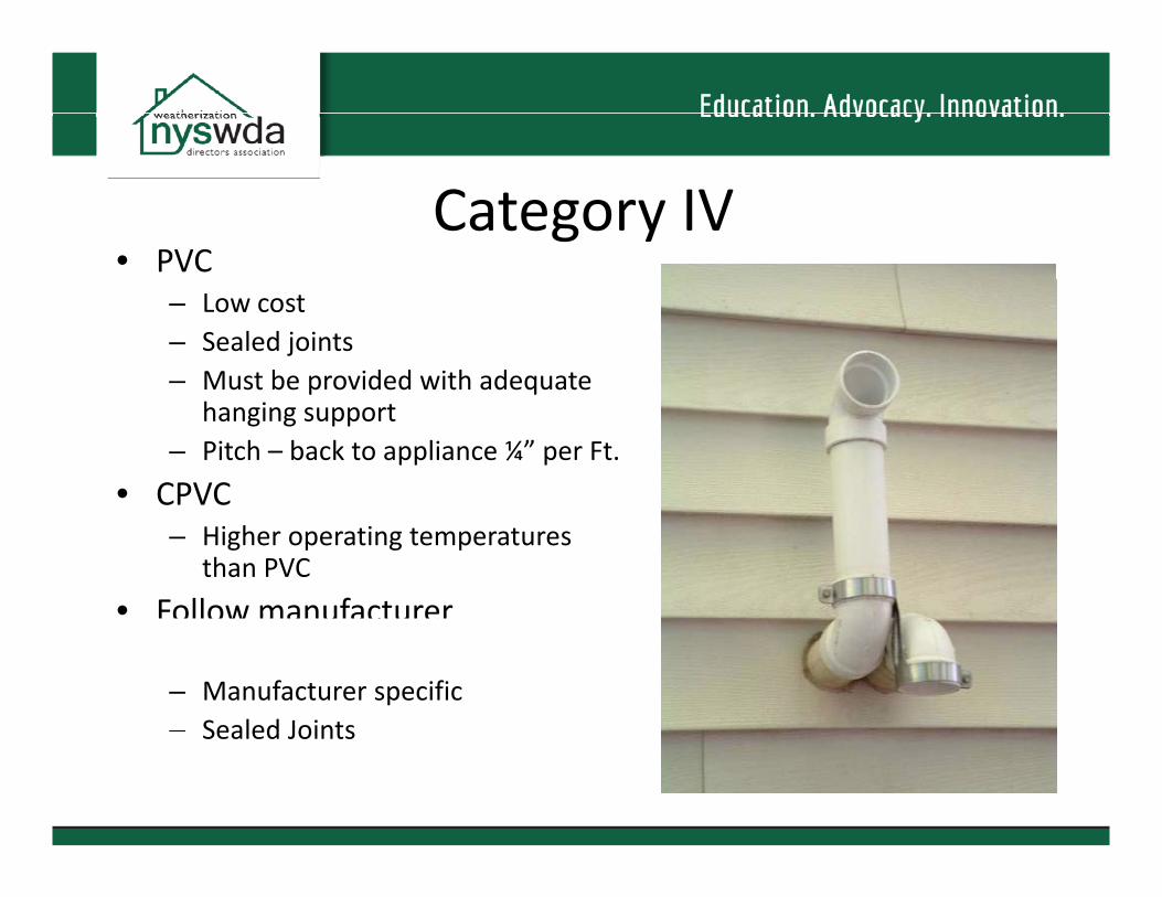
Category IV • PVC
– Low cost – Sealed joints – Must be pprovided with adeqquate
hanging support – Pitch – back to appliance ¼” per Ft.
• CPVC – Higher operating temperatures
than PVC
• Follow manufacturerFollow manufacturer instructions – Manufacturer specific – Sealed JointsSealed Joints

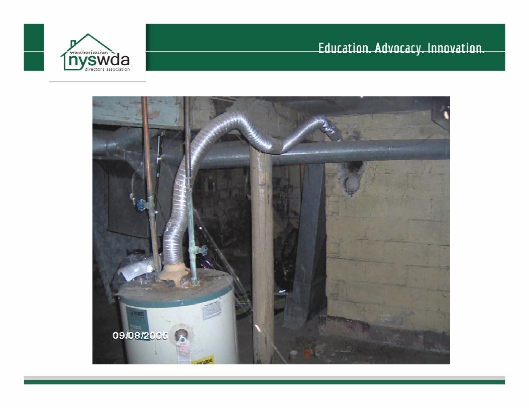
Orphaned GAS Hot Water • When removing a heating appliance from an existingCategory I flue the hot water heater may becomeCategory I flue the hot water heater may become stranded or “orphaned” in a vent that is oversized.
• Problem‐Potential Backdrafting • S l i ( h i S b kd f iSolution (IF the unit IS backdrafting)):
– Reline if a masonry chimney with a flexible liner or “B” vent
– Power Vent – Replace water heater
• Direct vent • Electric
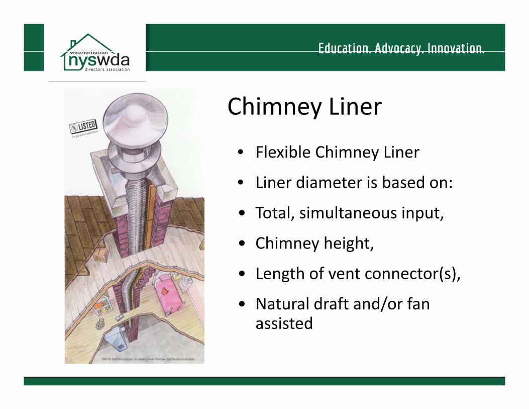
Chimney Liner
• Flexible Chimney Liner
• LiLiner didiametter iis bbasedd on:
• Total, simultaneous input,
• Chimney height,
• Lenggth of vent connector(s),( )
• Natural draft and/or fan assisted


–
System Sizing
• What is a (BTU)? British Thermal UnitBritish Thermal Unit
– The amount of heat energy required to raise 1 pound ofwater 1 degree Fahrenheit
• H t L d C l lHeat Load Calculati tions – Volume of House – Insulation Values‐Walls, Ceiling, etc… – Windows and Doors – Air infiltration – Distribution SystemDistribution System

Reading and Writing Proposals and Specifications
•• Should be as complete as possible and Should be as complete as possible and indicate:
I t ll ti f t i t ti – Installation per manufacturers instructions – All local codes will be followed
– System size
– Warrantee for parts and labor – Timeframe for completion
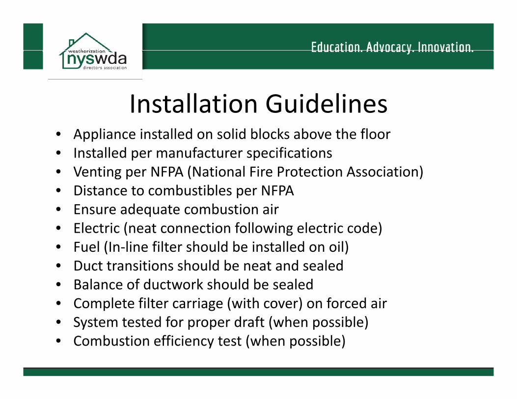
Installation Guidelines • Appliance installed on solid blocks above the floor • Installed per manufacturer specifications • Venting per NFPA (National Fire Protection Association)A (National Fire Protection Association) Venting per NFP• Distance to combustibles per NFPA • Ensure adequate combustion air • ElElecttriic ((neat connectition followiing ell t i ectric cod )de)t f ll • Fuel (In‐line filter should be installed on oil) • Duct transitions should be neat and sealed • Balance of ductwork should be sealed • Complete filter carriage (with cover) on forced air • System tested for proper draft (when possible)System tested for proper draft (when possible) • Combustion efficiency test (when possible)

MManagiing YYour C tContracttor
•• What are you folks doing now? What are you folks doing now?

–
Partnerships • HEAP Emergency Repair and Replacement Program
Only during heating seasonOnly during heating season – Emergency response to “no heat”
• Weatherization Assistance Program – Efficiency is primary goal – Last resort when responding to emergency
• NYSERDANYSERDA‐EmPower and Home PerformanceEmPower and Home Performance – Efficiency repairs eligible – Generally does not have funds for replacement unlesscoordinatedcoordinated

QQuesti tions??

ContactsContacts
Andy Stone New York State Weatherization Directors Association
315‐701‐0440
Related Documents