HEAP LEACHING TECHNIQUE in MINING Within the Context of BEST AVAILABLE TECHNIQUES (BAT) Caner Zanbak, PhD Supported by Euromines – The European Association of Mining Industries, Metal Ores & Industrial Minerals November, 2012

Welcome message from author
This document is posted to help you gain knowledge. Please leave a comment to let me know what you think about it! Share it to your friends and learn new things together.
Transcript
HEAP LEACHING TECHNIQUE in MINING
Within the Context of
BEST AVAILABLE TECHNIQUES (BAT)
Caner Zanbak, PhD
Supported by
Euromines – The European Association of Mining Industries, Metal Ores &
Industrial Minerals
November, 2012
Introductory Statement by Euromines
The objective of mining is to provide valuable minerals needed by the society. For doing so,
mining companies extract resources from mineral deposits around the globe and use different
techniques to recover the valuable mineral resources from the ore.
The choice of a suitable technique, which is both environmentally sound and economically
viable, to process mineral resources very much depends on the type of ore which is mined as
well as of the physical conditions linked to the location of the mine site.
Heap leaching is a tried and tested mining technique enabling the processing of different kinds
of ores which could not otherwise be exploited under viable economic conditions. Modern day
heap leaching, which has a relatively low level of energy consumption, is for example
successfully used for the beneficiation of certain types of gold ores in Turkey . It contributes to
the substantial development of a sustainable gold mining sector in that country and has the
potential to help fostering sustainable supply of raw materials in other countries within Europe.
This document, prepared by the Turkish Gold Miners Association and supported by Euromines,
has benefited from the contributions of Euromines’ Members as well as of experts from several
mining companies, both within Europe and abroad. It aims at:
(i) presenting an up to date overview of modern day heap leaching in mining;
(ii) providing the relevant information to consider heap leaching in the context of Best
Available Techniques (BAT) as defined by the relevant regulatory instruments of the
European Union.
In this respect, the author would like to express his particular gratitude to the following experts
for their valuable contribution to the present work:
- David A. Bickford, General Manager and Chairman of Tüprag Metal Mining, Turkey
- Anthony Crews, Vice President & Principal, The Mines Group, Reno, Nevada, USA
- Miguel Diaz, Technical Director, AMEC Earth & Environmental, UK
- Larry Enloe, Manager, N. American Regional Business Unit, Barrick Gold, Utah, USA.
- Louise Grondin, Senior VP, Agnico-Eagle, Sweden
- Corina Hebestreit, Director, Euromines, Brussels
- Robert Rose, CEO, Andina Minerals, Toronto, Ontaria, Canada (formerly KCA, Reno,
Nevada)
- Marja Riekkola-Vanhanen, Sr. Biotechnology Advisor, Talvivaara Nickel Mine, Finland
i
HEAP LEACHING TECHNIQUE in MINING
Within the Context of
BEST AVAILABLE TECHNIQUES (BAT)
TABLE OF CONTENTS
1. INTRODUCTION............................................................................................................... 1
2. ORE BENEFICIATION METHODS IN MINING ........................................................ 3
3. LEACHING IN THE NATURAL ENVIRONMENT ..................................................... 5
4. LEACHING LIXIVIANTS USED IN MINING .............................................................. 6
5. BASIC EFFICIENCY FACTORS IN HEAP LEACH PROCESS ................................ 6
6. LEACHING TECHNIQUES USED IN MINING ........................................................... 9
6.1 Historical Leach Mining ............................................................................................... 10
6.2 Modern Day Leach Mining .......................................................................................... 10
7. DESIGN COMPONENTS OF A HEAP LEACH UNIT ............................................... 13
7.1 Agglomeration ............................................................................................................... 13
7.2 Leach Pads ..................................................................................................................... 14
7.3 Leach Pad Bottom - Ground Surface .......................................................................... 15
7.4 Leach Pad Liner System ............................................................................................... 16
7.5 Ponds –Solution Management ...................................................................................... 17
7.6 Ore Heap ........................................................................................................................ 19
7.7 Lixiviant Solution Application and Pregnant Solution Collection ........................... 20
7.8 Ore Stacking .................................................................................................................. 21
7.9 Heap Rinsing and Pad Closure ................................................................................... 22
7.10 Stability Assessment of Heap Leach Pads ................................................................... 22
7.10.1 Geotechnical Site Investigations and Material Testing: .................................... 23
7.10.2 Stability of Leach Piles: ...................................................................................... 24
8. REGULATORY DEFINITION OF “BEST AVAILABLE TECHNIQUES” ............ 25
8.1 Annex IV of the Directive 2008/1/EC: ......................................................................... 25
8.2 BREF on Management of Tailings and Waste-Rock in Mining Activities .............. 26
8.3 Framework Concept for Evaluation of a Technique in Consideration as a BAT ... 27
9. CONCLUSIONS ............................................................................................................... 32
10. REFERENCES CITED .................................................................................................... 33
1
HEAP LEACHING TECHNIQUE in MINING
Within the Context of
BEST AVAILABLE TECHNIQUES (BAT)
1. INTRODUCTION
The objective of the Directive 2006/21/EC on the management of waste from extractive
industries and amending Directive 2004/35/EC (the Mining Waste Directive) is to prevent or
reduce as far as possible any adverse effects on the environment or on human health which are
brought about as a result of the management of waste from the extractive industries.
Accordingly, the Mining Waste Directive covers the management of waste from land-based
extractive industries, that is to say, the waste arising from the prospecting, extraction,
treatment and storage of mineral resources and from the working of quarries. It requires that
measures taken to achieve its objective are based inter alia on Best Available Techniques
(BATs), as defined by Directive 96/61/EC of 24 September 1996 concerning integrated
pollution prevention and control (IPPC), which has been codified by Directive 2008/1/EC.
Directive 2008/1/EC of 15 January 2008 concerning integrated pollution prevention and
control (the IPPC Directive), whose objective is to prevent or reduce emissions in the air,
provides a detailed definition of „best available techniques‟. Directive 2008/1/EC will be
repealed in January 2014 by Directive 2010/75/EU of 24 November 2010 on industrial
emissions which provides for a similar definition of „best available techniques‟.
The European Integrated Pollution Prevention and Control (IPPC) Bureau, established under
the framework of European Commission's Joint Research Centre (JRC), is entrusted with the
task to develop reference documents on Best Available Techniques, called BREFs, through an
exchange of information involving the relevant stakeholders, notably the Member States and
the industry. BREFs are the main reference documents used by competent authorities in
Member States when issuing operating permits for installations that represent a significant
pollution potential in Europe.
A revised BREF document on “Management of Tailings and Waste-Rock in Mining
Activities” was adopted in January 2009, in accordance with article 21(3) of the Mining Waste
Directive. It describes BAT that can be considered as examples of “good practice” for
mineral processing, tailings and the waste-rock management of ores that have the potential
for a strong environmental impact. This BREF document covers fourteen different metals,
including gold, that are mined and/or processed in the European Union (EU-15), the acceding
countries, the candidate countries and Turkey,
Heap leaching techniques are briefly addressed in this version of the BREF document but not
sufficiently described.
The objective of this document is to provide an overall review of:
leaching process in mining practice, with special emphasis on available techniques
applicable for Heap Leaching of very low grade ores that are not considered economical
2
to treat with other BATs ,
availability of applicable technologies by global suppliers,
effectiveness of technologies used in Heap Leaching to control emissions for protection
of the environmental media, and
evaluation of the heap leaching process and available techniques within the context of
regulatory BAT concept as a technical supplement to the existing BREF document.
Heap leaching is BAT for suitable ores because it allows the economical processing of ore that
would otherwise be uneconomic under conditions that can technically achieve regulatory
acceptable levels of environmental risk mitigation.
All of the materials used in heap leaching process and industry specifications of materials are
available globally. Also, slope stability evaluations of stacked heap leach pads are performed
using standard geotechnical engineering principles and practice. Therefore, in accordance with
the definition of BAT provided by the IPPC Directive and with the objectives of the Mining
Waste Directive, emphasis is given to emission minimization concepts for the Heap Leaching
Technique and design specifications for engineered materials and heap stability analysis
methods are not prescribed in this document.
3
2. ORE BENEFICIATION METHODS IN MINING
The primary objective of mining is to supply raw materials to downstream users, extracted from
ore deposits in the earth‟s crust, using applicable excavation and ore enrichment processes with
economically feasible and environmentally sound engineering operations.
In a typical metal ore mining operation, ores are selectively excavated from an open pit or
underground workings, crushed and milled for futher treatment in ore beneficiation units for
enrichment and/or production of metals and metal compounds.
There are several mainframe ore preparation/beneficiation methods available in mining practice
based on physical, chemical and smelting processes.
Concentration:
Gravity concentration (Heavy/dense media, Shaking tables, Spiral separators, jigs)
Electrostatic separation
Magnetic separation
Flotation
Hydrometallurgy
Leaching
Electrolysis
Precipitation (cementation)
Pyrometallurgy
Calcining, Roasting
Smelting
Refining
All of these processes require crushing and/or, grinding/milling of run-of-mine ores for liberation
of mineral particles of interest for efficient application of appropriate processes of beneficiation.
Selection of a beneficiation technology is based on economic viability which is directly
dependent on the:
ore type (namely, oxide or sulphide),
mineral composition, matrix features of ore
reserves and average grade (based on the “cut-off grade”) of the ore.
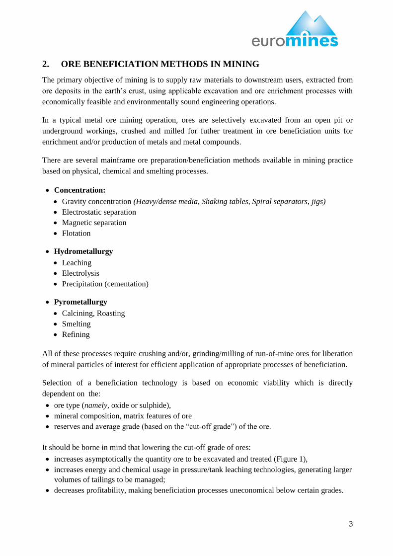
It should be borne in mind that lowering the cut-off grade of ores:
increases asymptotically the quantity ore to be excavated and treated (Figure 1),
increases energy and chemical usage in pressure/tank leaching technologies, generating larger
volumes of tailings to be managed;
decreases profitability, making beneficiation processes uneconomical below certain grades.
4
Figure 1 – Relationship Between Excavation Quantity and Average Grade of Mined Ore
as a function of “cut-off grade” (modified from McNab, B., 2006)
In response to global increases in metal commodity prices, the low grade base metal and precious
metal ores (<1% copper, <1g/ton gold, < 0.5% nickel) previously considered uneconomical,
became feasible with introduction of heap leaching technologies (Marsden, 2009).
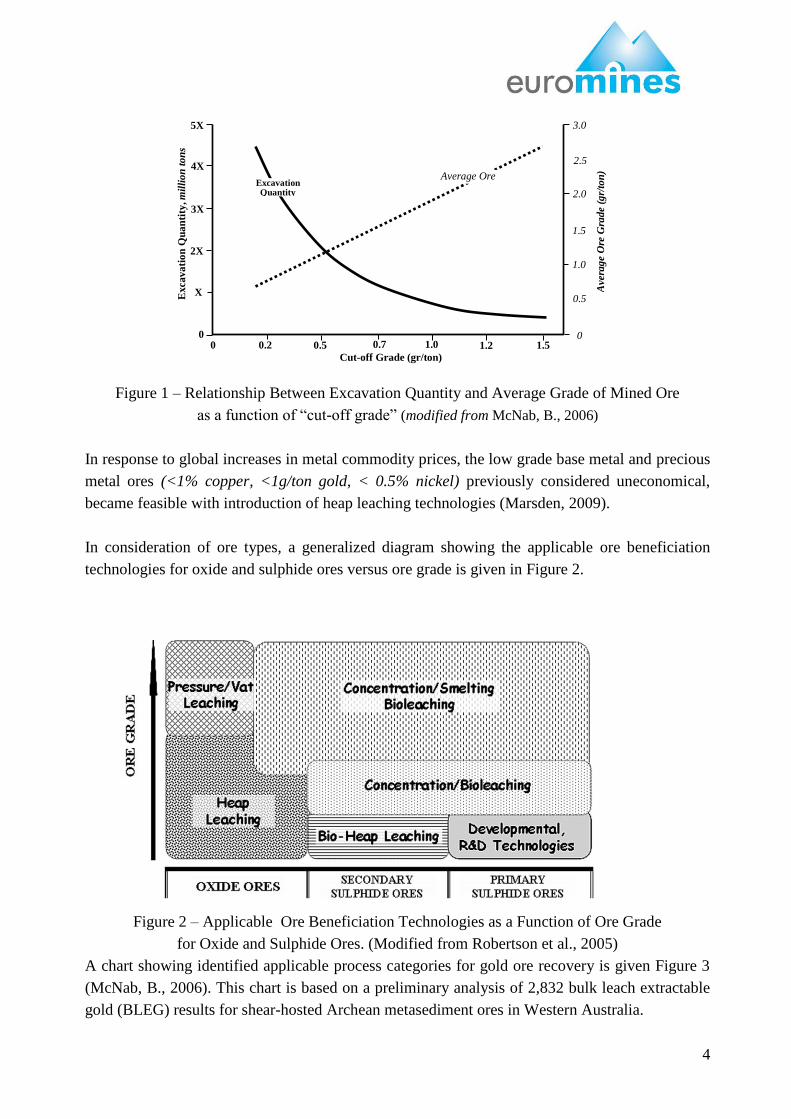
In consideration of ore types, a generalized diagram showing the applicable ore beneficiation
technologies for oxide and sulphide ores versus ore grade is given in Figure 2.
Figure 2 – Applicable Ore Beneficiation Technologies as a Function of Ore Grade
for Oxide and Sulphide Ores. (Modified from Robertson et al., 2005)
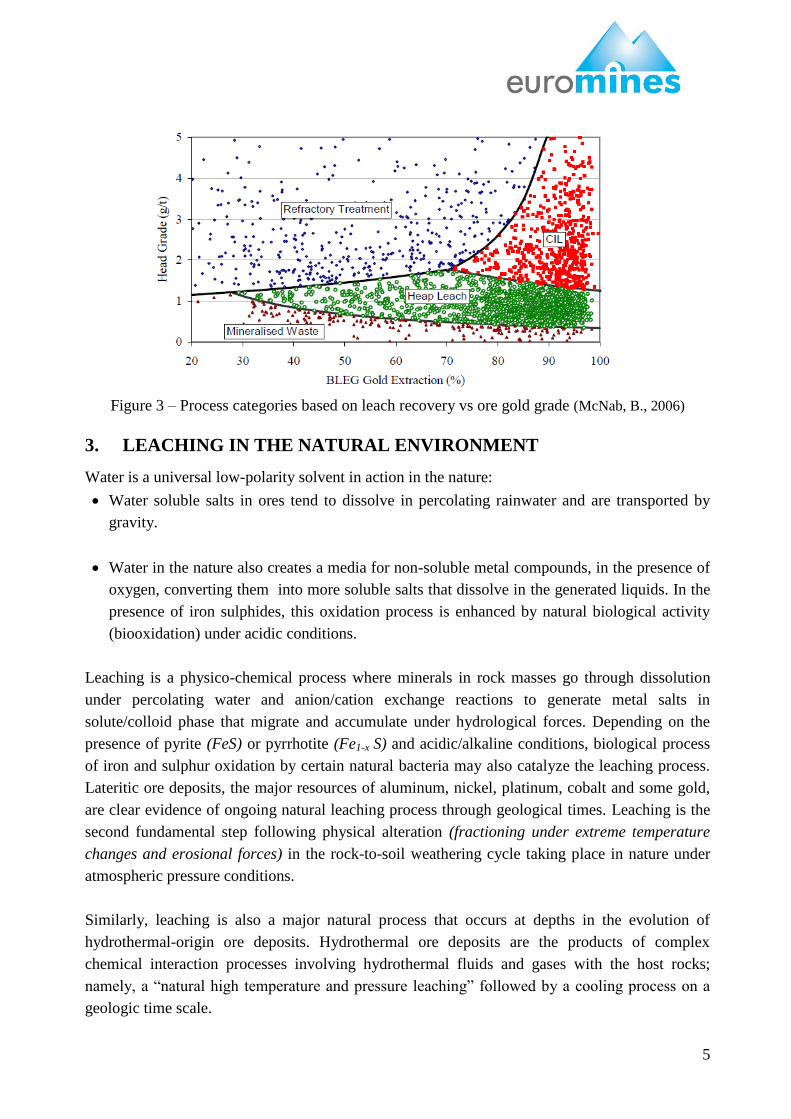
A chart showing identified applicable process categories for gold ore recovery is given Figure 3
(McNab, B., 2006). This chart is based on a preliminary analysis of 2,832 bulk leach extractable
gold (BLEG) results for shear-hosted Archean metasediment ores in Western Australia.
Average Ore
Grade Excavation Quantity
Cut-off Grade (gr/ton)
0 0.2
5
0.5
0
0.7
5
1.0
0
1.2
5
1.5
0
Excava
tio
n Q
ua
nti
ty, m
illi
on
to
ns
X
2X
3X
4X
5X
0
Avera
ge O
re G
rade (
gr/
ton
)
0
0.5
0
1.0
0
1.5
0
2.0
0
2.5
0
3.0
0
5
Figure 3 – Process categories based on leach recovery vs ore gold grade (McNab, B., 2006)
3. LEACHING IN THE NATURAL ENVIRONMENT
Water is a universal low-polarity solvent in action in the nature:
Water soluble salts in ores tend to dissolve in percolating rainwater and are transported by
gravity.
Water in the nature also creates a media for non-soluble metal compounds, in the presence of
oxygen, converting them into more soluble salts that dissolve in the generated liquids. In the
presence of iron sulphides, this oxidation process is enhanced by natural biological activity
(biooxidation) under acidic conditions.
Leaching is a physico-chemical process where minerals in rock masses go through dissolution
under percolating water and anion/cation exchange reactions to generate metal salts in
solute/colloid phase that migrate and accumulate under hydrological forces. Depending on the
presence of pyrite (FeS) or pyrrhotite (Fe1-x S) and acidic/alkaline conditions, biological process
of iron and sulphur oxidation by certain natural bacteria may also catalyze the leaching process.
Lateritic ore deposits, the major resources of aluminum, nickel, platinum, cobalt and some gold,
are clear evidence of ongoing natural leaching process through geological times. Leaching is the
second fundamental step following physical alteration (fractioning under extreme temperature
changes and erosional forces) in the rock-to-soil weathering cycle taking place in nature under
atmospheric pressure conditions.
Similarly, leaching is also a major natural process that occurs at depths in the evolution of
hydrothermal-origin ore deposits. Hydrothermal ore deposits are the products of complex
chemical interaction processes involving hydrothermal fluids and gases with the host rocks;
namely, a “natural high temperature and pressure leaching” followed by a cooling process on a
geologic time scale.
6
4. LEACHING LIXIVIANTS USED IN MINING
The primary objectives of leaching processes applied in mining are the selective dissolution of
metals of interest in ores, segregate the loaded (pregnant) solution from solids and recover
available metals either in metal compounds or in metallic forms through further
hydrometallurgical treatment.
Lixiviants are chemical solutions used in leach mining to enhance dissolution of metals in ores.
Sulphuric acid and cyanide salts are the most common demonstrated lixiviants used in heap or
vat (tank) leaching processes applied under atmospheric conditions. Thiourea and thiosulphate
are also known lixiviants for copper and gold ores; however, they are not used in world mining
practice for their more complicated chemical management issues and environmental concerns.
Currently, there are no successfully demonstrated applications of these lixivants on an industrial
scale that can be considered within the context of Best Available Tecniques (BATs).
5. BASIC EFFICIENCY FACTORS IN HEAP LEACH PROCESS
Recovery rates of metals (in percentage of the ore grade) are an indicator of leaching
effectiveness. In practice, the recovery rate is characterised by the dissolution kinetics of metals,
namely:
percentage of metal of interest in ore transferred into the leach solution, and
time required for metal dissolution.
Dissolutioning of metals in heap leaching process is mainly controlled by:
- degree of liberation of mineral particles in the heap – feed particle size,
- ability of lixiviants to have good contact with the metal bearing mineral grains (heap
permeability, agglomeration),
- dissolution potential of the metals/mineral composition – Leach Kinetics,
- bacterial activity on metal sulphides,
- oxygen.
a) Degree of mineral liberation – crushed ore particle size: Ore is crushed to certain
particle size distribution prior to stacking on the leach pads. The objective of this process
is to increase exposure of the mineral grains to lixiviants. Ore crushing is generally done
in multiple steps, where in primary crushing the particle size is reduced down to 10 to 15
cm and in secondary/tertiary crushing the particles are reduced to the optimum size
while producing as many microcracks in the ore particle as possible. If the ore is very
permeable, little or no crushing may be necessary because of the advanced degree of
natural liberation of the target metal. Such “run-of-mine” ore material can be placed
directly on the leach pad after minimal breakage following normal production related
7
blasting or even simple shoveling with mine equipment. There needs to be a distinction
between Oxide and Sulphide ores here as agreed beneficiation processes will vary
significantly.
Lixiviant contact with mineral grains: Assurance of thorough percolation of lixiviants
in the heap improves dissolution of metals. The percolation rate of the fluids should also
be slow enough to provide sufficiently long lived contact of the lixiviant with the ore
particle to dissolve the metals. Therefore, achieving a uniform heap permeability is
required for optimal flow of leach fluids throughout the heaped ore. The presence of fine
particles in the crushed ore tends to decrease permeability with heap height
consolidation loading. In cases where fine particles are present, agglomeration
techniques using cementitious additives or sulhuric acid solution for bio-heap leaching
can be applied to the crushed ore prior to stacking on the heap pad for optimization of
heap permeability. The height of a stacked heap is also a factor that controls
consolidation and permeability variations – in the case of cement agglomeration, a
greater –percentage will be added to lower lifts than upper lifts. Stacking methods are
also critical – i.e., radial conveyors, trippers, tipper trucks.
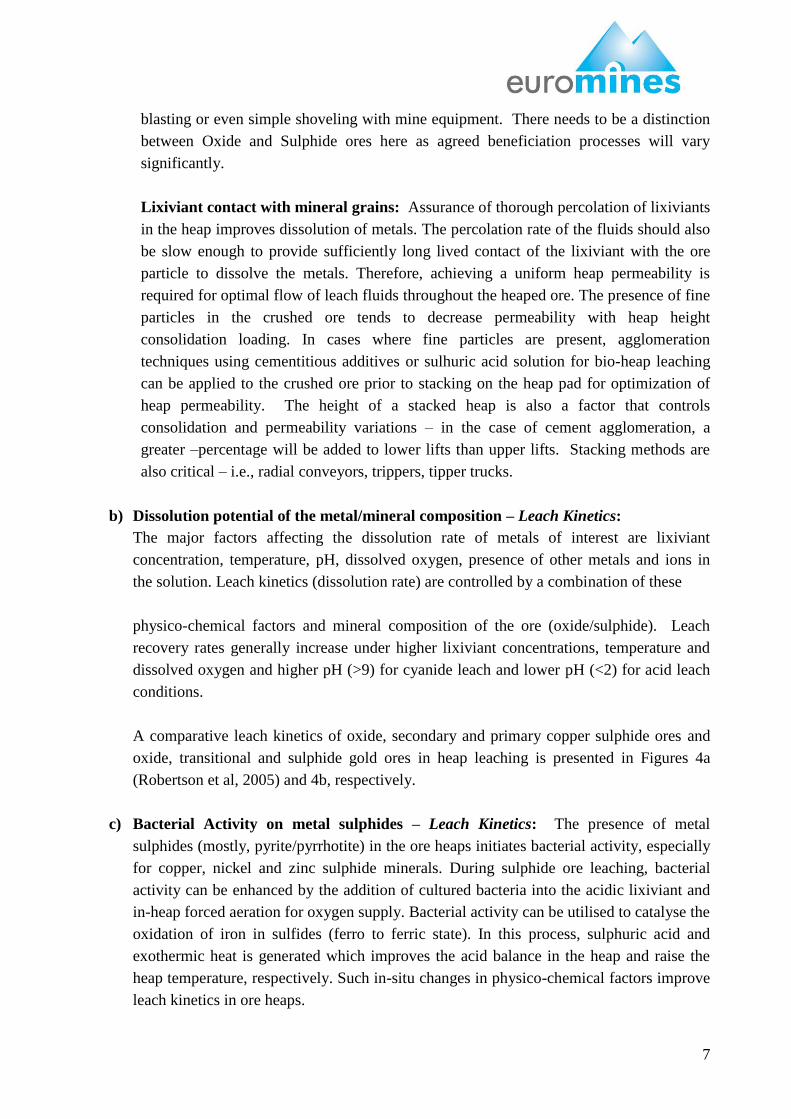
b) Dissolution potential of the metal/mineral composition – Leach Kinetics:
The major factors affecting the dissolution rate of metals of interest are lixiviant
concentration, temperature, pH, dissolved oxygen, presence of other metals and ions in
the solution. Leach kinetics (dissolution rate) are controlled by a combination of these
physico-chemical factors and mineral composition of the ore (oxide/sulphide). Leach
recovery rates generally increase under higher lixiviant concentrations, temperature and
dissolved oxygen and higher pH (>9) for cyanide leach and lower pH (<2) for acid leach
conditions.
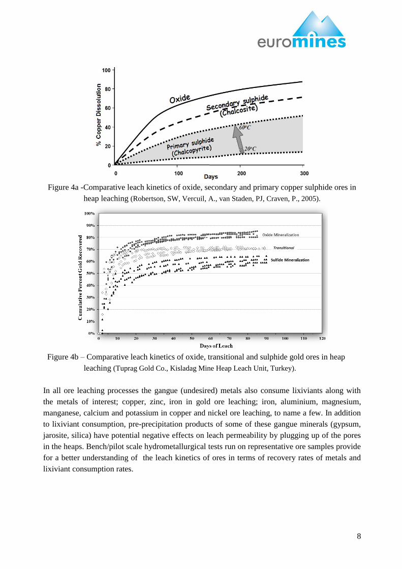
A comparative leach kinetics of oxide, secondary and primary copper sulphide ores and
oxide, transitional and sulphide gold ores in heap leaching is presented in Figures 4a
(Robertson et al, 2005) and 4b, respectively.
c) Bacterial Activity on metal sulphides – Leach Kinetics: The presence of metal
sulphides (mostly, pyrite/pyrrhotite) in the ore heaps initiates bacterial activity, especially
for copper, nickel and zinc sulphide minerals. During sulphide ore leaching, bacterial
activity can be enhanced by the addition of cultured bacteria into the acidic lixiviant and
in-heap forced aeration for oxygen supply. Bacterial activity can be utilised to catalyse the
oxidation of iron in sulfides (ferro to ferric state). In this process, sulphuric acid and
exothermic heat is generated which improves the acid balance in the heap and raise the
heap temperature, respectively. Such in-situ changes in physico-chemical factors improve
leach kinetics in ore heaps.
8
Figure 4a -Comparative leach kinetics of oxide, secondary and primary copper sulphide ores in
heap leaching (Robertson, SW, Vercuil, A., van Staden, PJ, Craven, P., 2005).
Figure 4b – Comparative leach kinetics of oxide, transitional and sulphide gold ores in heap
leaching (Tuprag Gold Co., Kisladag Mine Heap Leach Unit, Turkey).
In all ore leaching processes the gangue (undesired) metals also consume lixiviants along with
the metals of interest; copper, zinc, iron in gold ore leaching; iron, aluminium, magnesium,
manganese, calcium and potassium in copper and nickel ore leaching, to name a few. In addition
to lixiviant consumption, pre-precipitation products of some of these gangue minerals (gypsum,
jarosite, silica) have potential negative effects on leach permeability by plugging up of the pores
in the heaps. Bench/pilot scale hydrometallurgical tests run on representative ore samples provide
for a better understanding of the leach kinetics of ores in terms of recovery rates of metals and
lixiviant consumption rates.
9
6. LEACHING TECHNIQUES USED IN MINING
Comprehension of the natural leaching mechanism has led the way to discoveries and
developments in the modern hydrometallurgy techniques used in the beneficiation of low-grade
ores. Techniques employed in modern leaching technologies mimic the naturally occuring
leaching processes under optimized operational conditions for improved productivity.
Dump Leaching: is a technique; where, generally run-of-mine sulfidic copper ore dumps are
wetted with water and/or sulphuric acid as a lixiviant to leach copper salts. Application of this
technique is on prepared sites. Application to unprepared historical sites has been
discontinued due to environmental concerns and inefficiencies in copper solution recovery.
Heap Leaching: is a technique where run-of-mine or crushed (generally >5 mm) and/or
agglomerated ores are stacked over an engineered impermable pad, wetted with lixiviant
(solvent) chemicals under atmospheric conditions and leachate (metal loaded solutions) are
collected for metal reovery processes. Because percolation of the lixiviant solution through
the ore is acheived under gravity and atmosperic conditions, completion of metal recovery
requires longer time periods (weeks to months, even several years in bio-processes) for each
pad loading sequence compared to tank leaching (hours to days). Upon completion of heap
leaching, the processed ore stack is generally decommissioned in place; therefore, this
technique does not require use of a tailings disposal (spent ore repository) facility. In some
operations processing is done on a lined surface that is covered with stabilized surface (on/off
pad) to allow removal of the processed ore usually by loaders or mechanised equipment. The
processed ore is moved to a lined facility (spent ore repository) for final closure and
reclamation, with the stabilized/lined leach pad area is being reused.
Tank leaching: is a technique where crushed/milled ores or flotation concentrates are
chemically treated in open tanks under atmospheric pressure conditions to extract metal salts
from the ore at an accelerated rate. This technique, also called as “semi-closed system” in
layman terms, requires handling and grinding of all run-of-mine ores and disposal of
processed materials (tailings) in tailings impoundments, or if a heap leaching facility is
present, the dewatered tailings may be sent to the leach pad for a second round of leaching or
back to tank leaching after pressure oxidation or roasting to capture any residual metal..
Pressure Leaching: is a technique where ground ores or flotation concentrates are
chemically treated in reactors (autoclaves) under high pressure and temperature conditions to
extract metal salts from the ore in an accelerated rate. This technique, also called as “closed
system” in layman terms, requires handling and grinding of all run-of-mine ores and disposal
of treated materials (tailings) in impoundments.
In-Situ Leaching: is a technique used in the recovery of copper, salt/trona and uranium ores
in appropriate hydrogeological settings.
10
Primary factors in selection of applicable/appropriate leaching technique and lixiviant chemicals
are:
mineralogical composition/matrix features of the ore, and
economical feasibility based on head grade and reserve of the ore deposit, estimated
environmental management costs, forecasted commodity market prices and magnitude of
capital investment required for the project.
6.1 Historical Leach Mining
Soaking colored minerals and soils in water and decanting the colored liquid for clothing/rug
fiber dying is likely the oldest leaching practice used by humans. The earliest written records of
leaching as a mining technique can be found in V. Biringuccio‟s book of “Pirotechnica”
published in 1540 describing leaching of saltpeter (sodium/potassium nitrate) from decayed
nitrified organic matter or caliche (found mostly in Chile) and in Georgius Agricola‟s book of
“De Re Metallica” published in 1557 illustrating a heap leach to recover alum (aluminium
sulfate) for use in the cloth dying with a 40-day leach cycle (Habashi, 2005; Kappes, 2002).
In the 16th century, the extraction of copper by dump/heap leaching was known to be practiced in
the Harz mountains area in Germany and in Rio Tinto mines in Spain. In these operations, pyrite
containing some copper sulfide minerals were piled in the open air and left exposed for months to
the action of rain and air whereby oxidation and dissolution of copper took place.
The first uses of pressure leaching of bauxite ores with Na2CO3 and Na(OH) were in France and
St. Petersburgh in 1887 by L. LeChatelier and K.J. Bayer for recovery of Al(OH)3 and Al2O3.
The Bayer process is still used for Bauxite ore beneficiation (Habashi, 2005). Pressure leaching
has been in use since the 1890‟s for the recovery of metals from numerous ore types.
The first use of cyanide for leaching of gold and silver ores was in England in 1887 by J.S.
MacArthur. Worldwide application of the cyanidation process with heap and vat leaching and
gold recovery processes increased greatly during the 1900-1920 period. Heap leaching of gold
ore started to gain promenence in the late 1960‟s when it was applied on a large scale to low
grade ores that were uneconomic to procees by conventional tank leach methods.
6.2 Modern Day Leach Mining
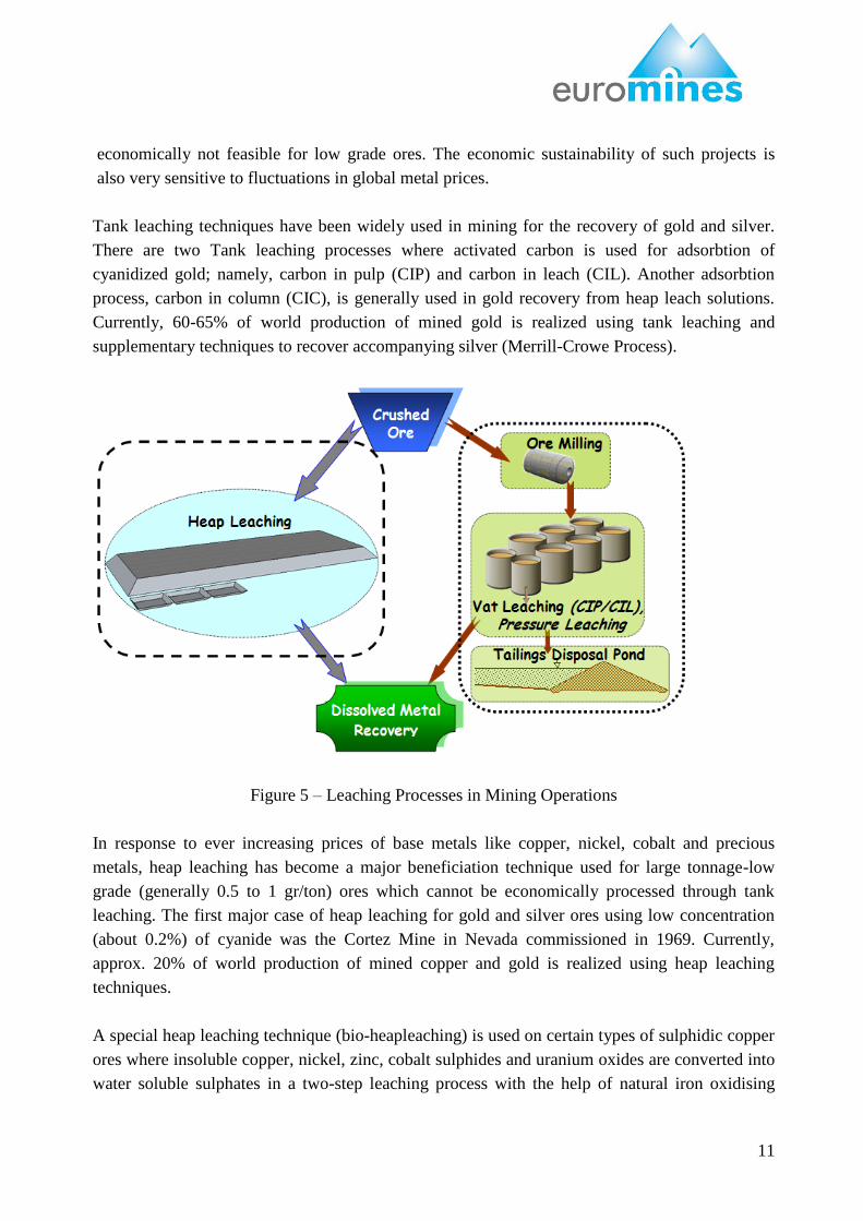
In mining operation flowsheets, leaching processes follow ore crushing, if required (Figure 5):
Crushed/Run-of-Mine ore is directly stacked on leach pads - Heap Leaching,
ore is further ground/milled (including flotation concentrates where applicable) and treated in
vessels - Pressure/Tank Leaching.
The pressure leaching technique has been in use in the beneficiation of mainly aluminium,
copper, nickel-cobalt, zinc-lead, gold-silver and platinum group element (PGE) ores.
Considering inherent initial high investment and operational cost, this technique is
11
economically not feasible for low grade ores. The economic sustainability of such projects is
also very sensitive to fluctuations in global metal prices.
Tank leaching techniques have been widely used in mining for the recovery of gold and silver.
There are two Tank leaching processes where activated carbon is used for adsorbtion of
cyanidized gold; namely, carbon in pulp (CIP) and carbon in leach (CIL). Another adsorbtion
process, carbon in column (CIC), is generally used in gold recovery from heap leach solutions.
Currently, 60-65% of world production of mined gold is realized using tank leaching and
supplementary techniques to recover accompanying silver (Merrill-Crowe Process).
Figure 5 – Leaching Processes in Mining Operations
In response to ever increasing prices of base metals like copper, nickel, cobalt and precious
metals, heap leaching has become a major beneficiation technique used for large tonnage-low
grade (generally 0.5 to 1 gr/ton) ores which cannot be economically processed through tank
leaching. The first major case of heap leaching for gold and silver ores using low concentration
(about 0.2%) of cyanide was the Cortez Mine in Nevada commissioned in 1969. Currently,
approx. 20% of world production of mined copper and gold is realized using heap leaching
techniques.
A special heap leaching technique (bio-heapleaching) is used on certain types of sulphidic copper
ores where insoluble copper, nickel, zinc, cobalt sulphides and uranium oxides are converted into
water soluble sulphates in a two-step leaching process with the help of natural iron oxidising
12
bacteria in an acidic environment enhanced with sulphuric acid. A successful example of bio-
heapleaching project is in operation since the beginning of 2009 in Sotkamo, Finland.
Since 2000, application of the heap leaching technique, using sulphuric acid as the lixiviant,
gained wide acceptance for recovery of nickel/cobalt from large deposits of very low grade (<
0.5%) lateritic ores, where pressure leaching has not been feasible.
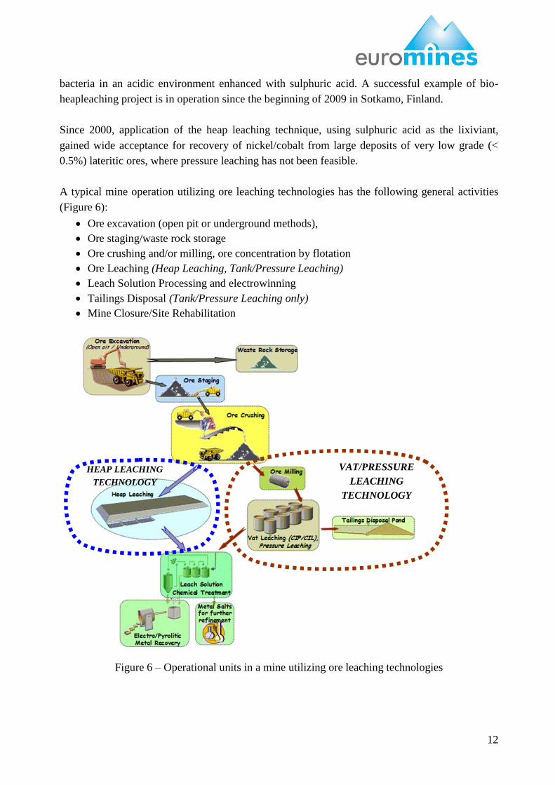
A typical mine operation utilizing ore leaching technologies has the following general activities
(Figure 6):
Ore excavation (open pit or underground methods),
Ore staging/waste rock storage
Ore crushing and/or milling, ore concentration by flotation
Ore Leaching (Heap Leaching, Tank/Pressure Leaching)
Leach Solution Processing and electrowinning
Tailings Disposal (Tank/Pressure Leaching only)
Mine Closure/Site Rehabilitation
Figure 6 – Operational units in a mine utilizing ore leaching technologies
HEAP LEACHING
TECHNOLOGY
VAT/PRESSURE
LEACHING
TECHNOLOGY
13
7. DESIGN COMPONENTS OF A HEAP LEACH UNIT
The objective of the “heap leaching process” is to chemically dissolve the metals out of “run of
Mine or crushed ore, stacked on an impermeable lined pad, into a solution where metals are
recovered through further chemical processing. Agglomeration may be applied on the crushed ore
prior to stacking in order to enhance stacked ore permeability characteristics and subsequent
percolation of lixiviant solution within the heap.
7.1 Agglomeration
Maintaining contact of leaching solution with crushed ore particles in the heap is important in
increasing leach efficiency. In practice, crushing generates fine particles of rocks in addition to
the clayey materials in the ore. The presence of excessive amounts of fine particles causes
clogging of the pores between the larger ore particles and leads to uneven distribution of the
leaching solution and can result in under leached zones in the heap.
Agglomeration of crushed ore, analogous to sintering of fine iron ore, provide coarser grains that
generate a more porous heap. Type II Portland cement and lime binders are used for gold ore to
prevent agglomerates from breaking up as leaching solution percolates through the heap
(Lewandoski, Kawatra, 2010). The need for agglomeration and the appropriate binder selection is
evaluated in bench and pilot-scale testworks on representative crushed ore samples for optimum
leaching rates and metal recoveries.
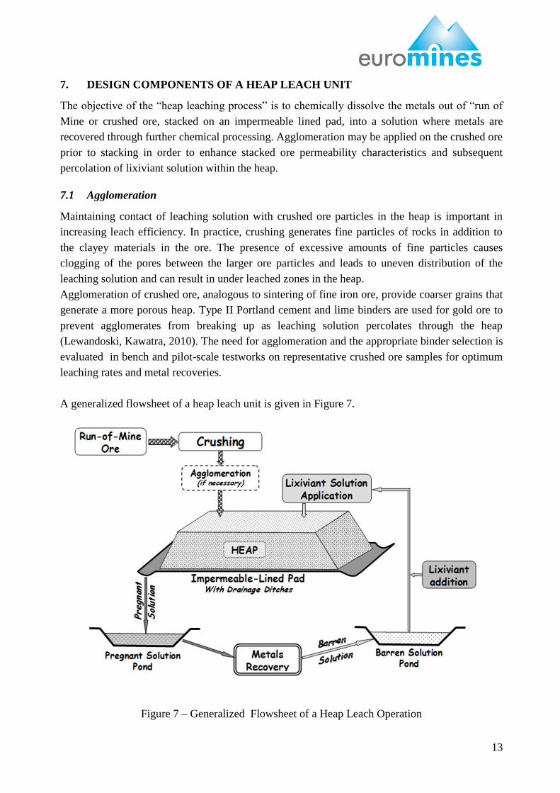
A generalized flowsheet of a heap leach unit is given in Figure 7.
Figure 7 – Generalized Flowsheet of a Heap Leach Operation
14
Basic components of a heap leaching unit are:
Heap,
Lined heap pad,
Solution collection system (usually gravity pipe system)
Lixiviant solution application
Ponds
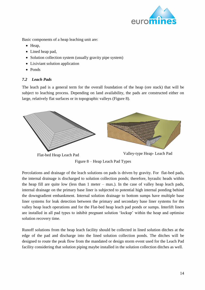
7.2 Leach Pads
The leach pad is a general term for the overall foundation of the heap (ore stack) that will be
subject to leaching process. Depending on land availability, the pads are constructed either on
large, relatively flat surfaces or in topographic valleys (Figure 8).
Figure 8 – Heap Leach Pad Types
Percolations and drainage of the leach solutions on pads is driven by gravity. For flat-bed pads,
the internal drainage is discharged to solution collection ponds; therefore, hyraulic heads within
the heap fill are quite low (less than 1 meter – max.). In the case of valley heap leach pads,
internal drainage on the primary base liner is subjected to potential high internal ponding behind
the downgradient embankment. Internal solution drainage to bottom sumps have multiple base
liner systems for leak detection between the primary and secondary base liner systems for the
valley heap leach operations and for the Flat-bed heap leach pad ponds or sumps. Interlift liners
are installed in all pad types to inhibit pregnant solution „lockup‟ within the heap and optimise
solution recovery time.
Runoff solutions from the heap leach facility should be collected in lined solution ditches at the
edge of the pad and discharge into the lined solution collection ponds. The ditches will be
designed to route the peak flow from the mandated or design storm event used for the Leach Pad
facility considering that solution piping maybe installed in the solution collection ditches as well.
Valley-type Heap- Leach Pad Flat-bed Heap Leach Pad
15
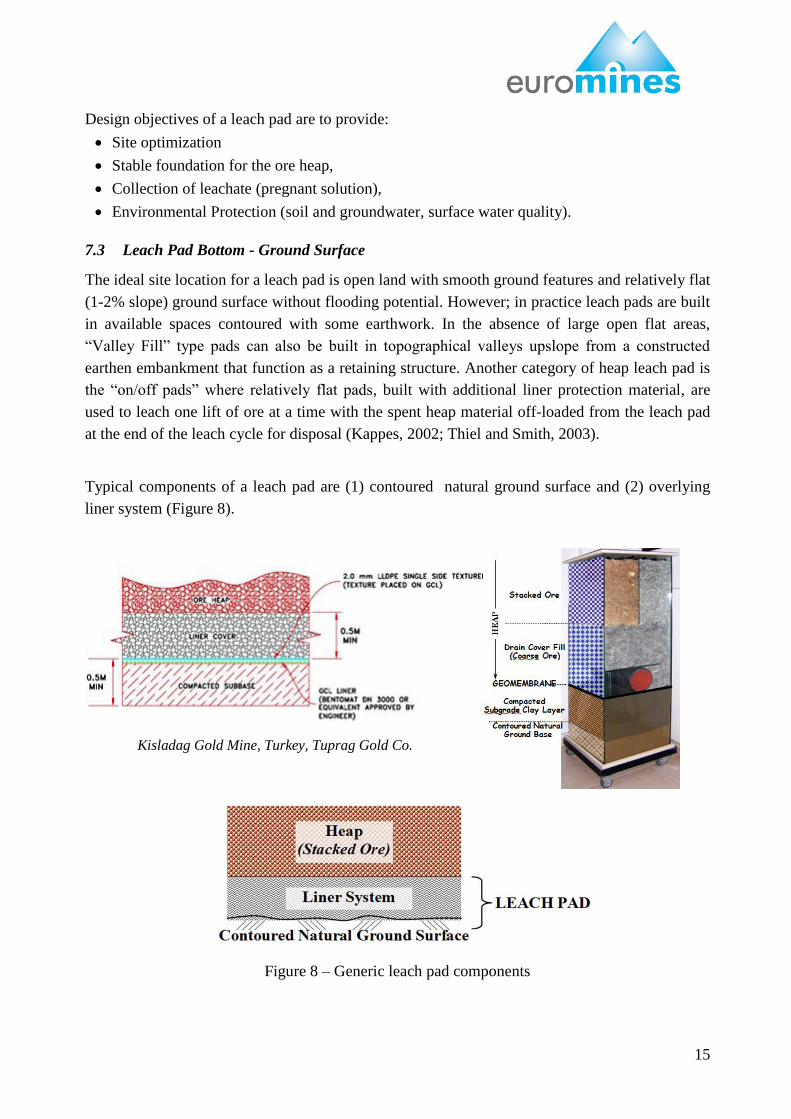
Design objectives of a leach pad are to provide:
Site optimization
Stable foundation for the ore heap,
Collection of leachate (pregnant solution),
Environmental Protection (soil and groundwater, surface water quality).
7.3 Leach Pad Bottom - Ground Surface
The ideal site location for a leach pad is open land with smooth ground features and relatively flat
(1-2% slope) ground surface without flooding potential. However; in practice leach pads are built
in available spaces contoured with some earthwork. In the absence of large open flat areas,
“Valley Fill” type pads can also be built in topographical valleys upslope from a constructed
earthen embankment that function as a retaining structure. Another category of heap leach pad is
the “on/off pads” where relatively flat pads, built with additional liner protection material, are
used to leach one lift of ore at a time with the spent heap material off-loaded from the leach pad
at the end of the leach cycle for disposal (Kappes, 2002; Thiel and Smith, 2003).
Typical components of a leach pad are (1) contoured natural ground surface and (2) overlying
liner system (Figure 8).
Figure 8 – Generic leach pad components
Kisladag Gold Mine, Turkey, Tuprag Gold Co.
16
The base of a leach pad is the natural ground surface which is modified by earthworks.
Undulations on the worked ground surface are acceptable as long as the surface gradients
facilitate liquid flows towards the collection ditches on the bottom and downgradient sides of the
heap. Basins (low spots within the pad) are not acceptable.
Geotechnical properties of the natural ground materials should provide adequate bearing capacity
under the loading by the ultimate heap geometry. In general, bearing capacity is not an issue of
concern for mine sites where the leach pads are constructed on geotechnically competent rock
formations; however, foundation bearing capacity should be evaluated during the pad design .
7.4 Leach Pad Liner System
The design objective of the leach pad liner is to contain and prevent the loss of solutions
generated in the overlying ore that will be subject to leaching process for both economic and
environmental reasons.
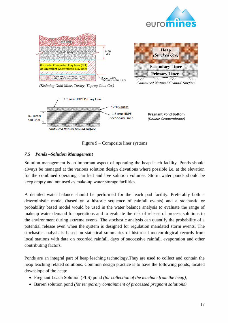
In current heap leach practice, the most preferred leach pad liner is the composite liner system.
Composite liners are made up of a sequence of (starting from bottom):
a compacted low permeability subgrade soil/clay liner (CCL) or a geosynthetic clay liner
(GCL) laid over the natural ground surface,
a leak-detection/collection system
a geomembrane liner HDPE/LLDPE (geotextile may be placed over for protection from
gravels above it)
an overlying drain cover fill (gravel and drain pipes)
Geosynthetic clay liners (GCL) are also used in leach pad construction, in lieu of low
permeability subgrade soil/clay liners (CCL), as they become commercially available in global
markets. Geosynthetic clay liners (GCL) are engineered materials providing similar or better
impermeability performance eliminating the need for an engineered impermeable clayey soil
subbase excavated from local borrow areas.
For certain segments of heap leach pads, where collected pregnant solution is collected (valley
fill leach pads), and the solution collection ponds, composite liner systems having double
geomembrane layers are used. Also, to enhance stability of the pads against sliding,
geomembranes with textured surfaces are used within the edges and toe sections of the pads.
Examples of typical composite liner systems are presented in Figure 9.
17
Figure 9 – Composite liner systems
7.5 Ponds –Solution Management
Solution management is an important aspect of operating the heap leach facility. Ponds should
always be managed at the various solution design elevations where possible i.e. at the elevation
for the combined operating clarified and live solution volumes. Storm water ponds should be
keep empty and not used as make-up water storage facilities.
A detailed water balance should be performed for the leach pad facility. Preferably both a
deterministic model (based on a historic sequence of rainfall events) and a stochastic or
probability based model would be used in the water balance analysis to evaluate the range of
makeup water demand for operations and to evaluate the risk of release of process solutions to
the environment during extreme events. The stochastic analysis can quantify the probability of a
potential release even when the system is designed for regulation mandated storm events. The
stochastic analysis is based on statistical summaries of historical meteorological records from
local stations with data on recorded rainfall, days of successive rainfall, evaporation and other
contributing factors.
Ponds are an integral part of heap leaching technology.They are used to collect and contain the
heap leaching related solutions. Common design practice is to have the following ponds, located
downslope of the heap:
Pregnant Leach Solution (PLS) pond (for collection of the leachate from the heap),
Barren solution pond (for temporary containment of processed pregnant solutions),
Pregnant Pond Bottom (Double Geomembrane)
(Kisladag Gold Mine, Turkey, Tüprag Gold Co.)
0.5 meter Compacted Clay Liner (CCL) or Equivalent Geosynthetic Clay Liner (GCL)
18
Intermediate solution pond (for recycling of leachates coming from the previously leached
ore or older heaps to the fresh ore or newer heaps in order to build up the solution metal
grade),
Overflow/Stormwater Pond (standby for emergencies).
Detoxification pond (standby for emergencies).
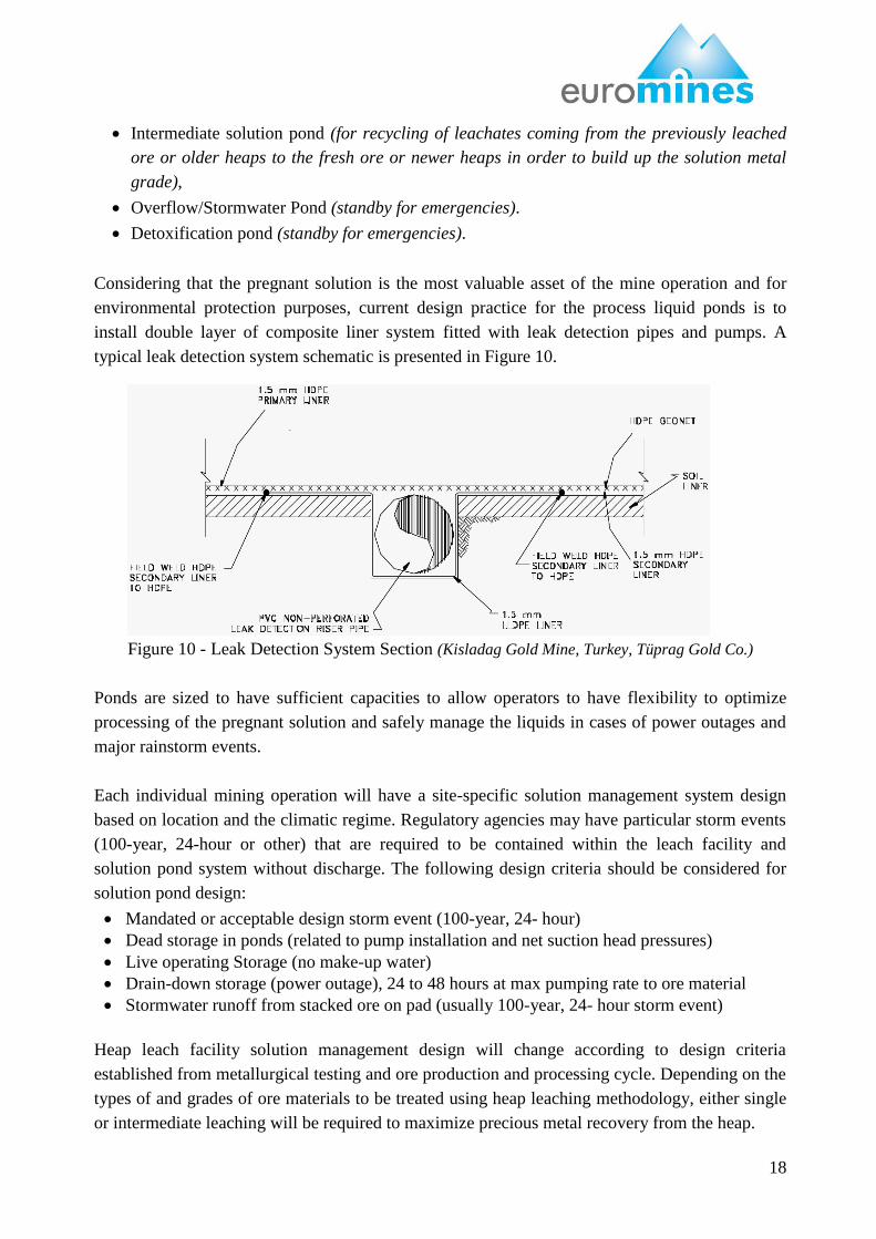
Considering that the pregnant solution is the most valuable asset of the mine operation and for
environmental protection purposes, current design practice for the process liquid ponds is to
install double layer of composite liner system fitted with leak detection pipes and pumps. A
typical leak detection system schematic is presented in Figure 10.
Figure 10 - Leak Detection System Section (Kisladag Gold Mine, Turkey, Tüprag Gold Co.)
Ponds are sized to have sufficient capacities to allow operators to have flexibility to optimize
processing of the pregnant solution and safely manage the liquids in cases of power outages and
major rainstorm events.
Each individual mining operation will have a site-specific solution management system design
based on location and the climatic regime. Regulatory agencies may have particular storm events
(100-year, 24-hour or other) that are required to be contained within the leach facility and
solution pond system without discharge. The following design criteria should be considered for
solution pond design:
Mandated or acceptable design storm event (100-year, 24- hour)
Dead storage in ponds (related to pump installation and net suction head pressures)
Live operating Storage (no make-up water)
Drain-down storage (power outage), 24 to 48 hours at max pumping rate to ore material
Stormwater runoff from stacked ore on pad (usually 100-year, 24- hour storm event)
Heap leach facility solution management design will change according to design criteria
established from metallurgical testing and ore production and processing cycle. Depending on the
types of and grades of ore materials to be treated using heap leaching methodology, either single
or intermediate leaching will be required to maximize precious metal recovery from the heap.
19
The design of the solution pond capacities is also predicated on:
the tonnage of ore to be processed per month or annum
the leach cycle time
solution application rate
the area under leach
the exposed lined area of pad not stacked with ore
Total ore tonnage to be stacked on the leach pad and final height of stacked ore
Design Considerations for Ponds
Dead Storage
in Ponds
Dead storage capacity in the solution ponds is normally the height of
solution that cannot be pumped out of the solution pond. This is dependent
on the design of the solution pond pump sump or pump vault. It is good
practice to have some available depth of solution to limit the risk of
damage to the pump when running dry.
Live Operating
Volume
Live operating volume is a design criteria specified by the mine operator
and generally selected as 4 to 12 hours of the design solution pumping
volume from the heaped ore.
Drain-Down
Storage
Typical drain-down storage occurs from a potential power outage when
the power is supplied from the local grid. Drain-down solution storage is
based on the volume of drain-down from the leach pad, which is calculated
as multiplication of the pumping rate by 24 hours where a stand-alone
power supply specifically designated for solution pond pumping systems is
installed and tested on a regular basis (biweekly or monthly). Depending
on the site location, drain-down storage is typically the largest volume
considered in the pond sizing design calculations.
Storm water
Runoff
The objective of the storm water pond is to retain runoff solutions and
empty the pond as expediently as possible. Best practice is to design the
storm water runoff volume for the total constructed leach pad area to
include exposed leach areas both under leach, non-leached, and exposed
geosynthetic liner at the various constructed phases of the leach pad.
Infiltration of storm water into the heap or material will take time to filter
down to the collection piping system and is generally not considered as an
influencing factor in the storm water containment design.
In the event of a possible release of process solutions from the ponds system during truly extreme
storm event sequences, good practice is to have cyanide neutralizing system in place for precious
metal operations.
Netting, use of air cannons, plastic balls or other floating devices to cover the entire surface of
process ponds are quite effective tools to minimize direct access of migratory birds to the ponds.
7.6 Ore Heap
A heap is a stacked up “run of mine” or crushed ore laid on a leach pad prior to application of
leach solution. Crushed and/or agglomerated ore can be stacked on the heap leach pad liner
20
system liner by either truck dumping or via telescopic/grasshopper conveyor belts with travelling
bridges (radial stacker) in sequential lifts. Conveyor stacking, especially for agglomerated ore
cases are commonly used for handling of large quantity of crushed material for its ease/mobility,
more homogeneous ore grain size distribution in the heaps and its favorable economics over truck
loading of leach pads. Also, equipping conveyors with automated water sprays, together with
conveyor stacking has a practical advantage or pre-wetting the ore material for leaching and
providing dust control. “Weak Leachate (with low metal content)” is commonly added into the
agglomeration process as a supplement for water prior to stacking of agglomerated ore on the
leach pads.
Gold and silver heap leach pads add lime to the ore being put on the pad for pH control. Lime
can be added on top of a crushed ore conveyor or on top of an ore truck before it dumps on the
leach pad.
Segregation of fines from coarse material during ore stacking is a common issue observed in
loading of heaps. Truck loading is particularly susceptible to segregation of ore material with
fines being concentrated in the upper section of the ore lift. Conveyor stacking of moist ore
material substantial reduces segregation of the ore.. Therefore, special care is needed for even
distribution of crushed/agglomerated ore in order to obtain uniform grain size distribution and
permeability in leach heaps.
7.7 Lixiviant Solution Application and Pregnant Solution Collection
The objective of lixiviant application is to achieve uniform and complete wetting of ore through
continuous percolation of liquids between the ore particles. Lixiviant solutions are applied on the
top surface of the heaps using either irrigational spraying or drip irrigation techniques. Selection
of spraying or drip irrigation is generally based on the climatic conditions of the site taking into
account the evaporation rate and freezing potential. Currently, drip irrigation is the more
commonly applied technique in mining practice.
Cyanide (generally NaCN) and sulphuric acid are the most commonly used lixiviant chemicals in
gold/silver and copper/nickel leach mining, respectively. Lixiviant chemical concentrations in the
leach solution and feed application rates on the heaps are dependent on site-specific factors of:
permeability of the heap,
chemical depletion rate (chemical consumption by all metals in the heap)and,
climatic conditions (evaporation and extreme rain)
These criteria need to be evaluated by bench/pilot-scale tests on representative heap samples and
optimized during the heap leach operations.
21
The pregnant solution is drained into the pregnant ponds. High grade heap off-flow (pregnant)
solution is then processed by chemically stripping the dissolved metal salts in the pregnant
solution with the resultant solution sent to barren pond or back up to the heap leach pad. The
barren solution is then adjusted to correct chemical composition and pumped to the top of the
heap leach for reuse in the leaching cycle.
7.8 Ore Stacking
Crushed ore placement in the heap leach operations can be done either by trucks and/or by
conveyor systems.
Truck dumping generally causes segregation of the ore where the fines remain near the top
surface, and the coarse material rolls to the base of the lift creating a highly permeable zone at the
base. To control the degree of this segregation the ore may be partially agglomerated (wetted to
cause the fines to stick to the coarse material) prior to placing in the trucks. Short lifts also result
in less segregation. Truck dumping can also result in compaction of ore under the roadways on
top of the heap. To mitigate this problem, most operations rip the ore surface after stacking (prior
to leaching). However this requires substantial bulldozer traffic on the heap surface, which can
also lead to compaction and loss of permeability for some ores (Kappes 2002).
Conveyor stacking systems where wheels, discharge angle, and stinger position are all motorized
and are moved continuously by the operator as the heap is built, commonly include the following
equipment (Kappes 2002):
• One or more long (overland) conveyors that transport the ore from the crushing (and
agglomeration) plant to the heap. These may consist of conveyors up to several kilometers in
length.
• A series of "grasshopper" conveyors to transport the ore across the active heap area.
Grasshoppers are inclined conveyors some 30 meters long, with a tail skid and a set of wheels
located near the balance point.
• A transverse conveyor to feed the stacker-follower conveyor
• A stacker-follower conveyor, typically a horizontal mobile conveyor that retracts behind the
stacker
• A radial stacker 25 to 50 meters long, with a retractable 5 - 10 meter conveyor “stinger” at its
tip.
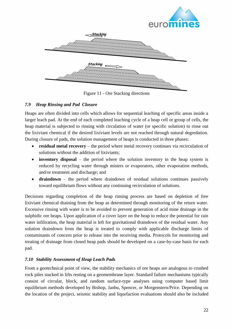
Ore Stacking typically proceeds in an upslope direction. It may proceed in the downslope
direction provided that the advancing face is stable (Figure 11).
In lateritic ore leaching operations, where the permeability of the clay-rich heap materials may
significantly decrease at the end of each leaching cycle (cycles may take over a year), use of an
intermediate geomembrane layer after each lift (inter-lift liners) may be considered to minimize
leach cycles and consumption of lixiviant specifically by iron containing minerals and for
effective collection of leach solutions.
22
Figure 11 - Ore Stacking directions
7.9 Heap Rinsing and Pad Closure
Heaps are often divided into cells which allows for sequential leaching of specific areas inside a
larger leach pad. At the end of each completed leaching cycle of a heap cell or group of cells, the
heap material is subjected to rinsing with circulation of water (or specific solution) to rinse out
the lixiviant chemical if the desired lixiviant levels are not reached through natural degredation.
During closure of pads, the solution management of heaps is conducted in three phases:
residual metal recovery – the period where metal recovery continues via recirculation of
solutions without the addition of lixiviants;
inventory disposal – the period where the solution inventory in the heap system is
reduced by recycling water through misters or evaporators, other evaporation methods,
and/or treatment and discharge; and
draindown – the period where draindown of residual solutions continues passively
toward equilibrium flows without any continuing recirculation of solutions.
Decisions regarding completion of the heap rinsing process are based on depletion of free
lixiviant chemical draining from the heap as determined through monitoring of the return water.
Excessive rinsing with water is to be avoided to prevent generation of acid mine drainage in the
sulphidic ore heaps. Upon application of a cover layer on the heap to reduce the potential for rain
water infiltration, the heap material is left for gravitational draindown of the residual water. Any
solution draindown from the heap is treated to comply with applicable discharge limits of
contaminants of concern prior to release into the receiving media. Protocols for monitoring and
treating of drainage from closed heap pads should be developed on a case-by-case basis for each
pad.
7.10 Stability Assessment of Heap Leach Pads
From a geotechnical point of view, the stability mechanics of ore heaps are analogous to crushed
rock piles stacked in lifts resting on a geomembrane layer. Standard failure mechanisms typically
consist of circular, block, and random surface-type analyses using computer based limit
equilibrium methods developed by Bishop, Janbu, Spencer, or Morgenstern/Price. Depending on
the location of the project, seismic stability and liquefaction evaluations should also be included
Stacking
Direction
Stacking
Direction
23
in the evaluation. Liquefaction stability is generally only considered when conditions such as
water table or solutions within the heap and susceptible foundation material types (saturated
loose, sandy type materials) are potentially at risk of losing strength during seismic events.
Circular, wedge or Block Failure stability analyses for soil slopes, available in geotechnical
engineering practice, are applicable to the heap slopes where the geomembrane layer is a well-
defined basal discontinuity with no cohesion and having a friction angle between 14-24o. For
pads having bottom slopes greater than 10%, various mechanisms, such as stability berms at the
toe or "shear berms" within the critical toe area of the heap, for stabilizing the heap can be
incorporated into the design. Heap stability is also commonly enhanced by designing a stability
toe with grades of less than 10 percent.
7.10.1 Geotechnical Site Investigations and Material Testing:
a) Pad Foundation: Detailed geotechnical investigations should be performed for the final heap
leach pad location. The geotechnical investigation should account for any adverse conditions
anticipated with the local geology and stratigraphy, for example, potential presence of deep
insitu weathered clay horizons (saprolitic soils) as encountered in humid and hot climatic
conditions.
The geotechnical investigation should include soil testing for materials to be used in the
construction of the heap leach facility and in-situ foundation materials expected to influence
stability. Geotechnical testing for pad foundation should at least include:
shear strength testing of the affected soil material types, and
consolidation testing towards assessment of bearing capacity, where applicable.
b) Stacked Ore Material: Characteristics of the ore material to be loaded on the leach pad
facility is determined by:
metallurgical testing as to determine the crush size and whether or not to agglomerate
using lime or cement.
geotechnical testing to determine the shear strength parameters and permeability under
various loading pressures (related to height and density of ore) expected for the heap
facility design. However, due to the difficulty of collecting and laboratory testing of
representative ron-of-mine samples, it is a common engineering practice to determine
the friction angle by field observations of the angle of repose during end dumping of
the stacked ore and cohesion is assumed to be zero, as a conservative approach.
Especially for clay-bearing run-of-mine ore materials, geotechnical parameters of the
stacked ore should be assessed by an experienced geotechnical professional as to short
and long term degradation of the material and its effects on shear strength parameters for
the heap stability and permeability .
c) Geosynthetics: interface friction angle testing on soil/ore-geosynthetic materials should be
conducted using materials representing the final heap leach liner configuration. These
materials include the subbase (Foundation), the impermeable secondary soil liner or
geosynthetic clay liner (GCL), the geosynthetic liner material (smooth or textured LLDPE,
HDPE or other), the high permeability gravel overliner for drainage and liner protection, and
24
the various ore material types. These material characteristics vary widely from site to site and
should be evaluated for individual sites and the particular liner configuration proposed for the
heap leach facility. Interface friction testing establishes the shear strength parameters to be
input into the stability model and should be evaluated by an experienced geotechnical
engineer.
7.10.2 Stability of Leach Piles:
a) Static Stability: Evaluation of the static stability of the ore heap should include all possible
mechanisms of failure modes (circular, block and random failure surfaces). Generally, the
stability failure mechanism for lined leach pad facilities are of block type failure along the
liner interface that typically has the lowest shear strength parameters. Circular failure
mechanisms may be critical when deep saprolitic type foundation materials underlie the heap
facility, particularly when associated with high water tables and potential generation of pore
water pressures due to rapid loading of the heap or seismic events. A static factor of safety
values of 1.3 and greater are considered acceptable good engineering practice.
b) Seismic Stability: Many mining operations are located in seismically active areas. A detailed
seismic evaluation of the particular mining location should be conducted to assess design
factors and ground accelerations to be considered in both structural (buildings) and
geotechnical design of water and tailings impoundments, and heap leach facilities. Typically,
seismic stability analyses for heap leach ore facilities are evaluated using conventional limit
equilibrium analysis with a pseudo-static coefficient.
Pseudo-static analysis is a very conservative procedure used as the first step in most seismic
stability analyses. It is not a dynamic analysis procedure and does not directly account for
dynamic/vibratory loading (i.e., the periodicity or cyclic character of the loads and the short
duration of loading). Rather, the procedure models seismic impacts by applying a uniform
horizontal static force to slices in a conventional limit equilibrium analysis. For a maximum
credible earthquake of up to a magnitude of 8.5, a pseudo-static acceleration coefficient of
0.15g could be used (Seed, 1979). Seismic factors of safety of greater than 1.0, as determined
by pseudo-static analyses, are acceptable for heap leach facilities as a good engineering
practice. In rare cases where seismic stability concerns cannot be satisfied using a simple
pseudo-static analysis, more detailed analyses of expected seismic displacement may be
required to asses seismic stability of the structures.
a) Liquefaction Potential: Liquefaction potential of heaps should also be taken into
consideration, especially in earthquake-prone regions (Thiel and Smith, 2003). Liquefaction
(flow slides) typically occurs when saturated or near-saturated (greater than 85%), loose
granular material contracts or collapses under some triggering event causing a sudden surge of
excess pore water pressure build-up and a reduction in shear strength. A classic triggering
event is seismic shaking. Seismically-induced liquefaction is typically limited to
approximately 20 m in depth, as the confining pressures at greater depths reduce susceptibility
to this type of failure. Generally, heap materials are maintained at saturation levels much less
than 85%; therefore, liquifaction risk is minimal.
25
8. REGULATORY DEFINITION OF “BEST AVAILABLE TECHNIQUES”
The concept of „Best available Technology‟ not entailing excessive costs was introduced by
Directive 84/360/EC of 28 June 1984 on the combating of air pollution from industrial plants.
This Directive was repealed by Directive 96/61/EC of 24 September 1996 concerning integrated
pollution prevention and control (IPPC), which has been codified by Directive 2008/1/EC.
Directive 2008/1/EC of 15 January 2008 concerning integrated pollution prevention and control
(the IPPC Directive), whose objective is to prevent or reduce emissions in the air, provides a
detailed definition of „best available techniques‟ (BATs). Directive 2008/1/EC will be repealed in
January 2014 by Directive 2010/75/EU of 24 November 2010 on industrial emissions which
provides for a similar definition of „best available techniques‟.
Article 2(12) of Directive 2008/1/EC defines BATs as follows:
"best available techniques" means:
the most effective and advanced stage in the development of activities and their methods
of operation which indicate the practical suitability of particular techniques for providing
in principle the basis for emission limit values designed to prevent and,
where that is not practicable, generally to reduce emissions and the impact on the
environment as a whole:
- "techniques" shall include both the technology used and the way in which the
installation is designed, built, maintained, operated and decommissioned,
- "available techniques” means those developed on a scale which allows
implementation in the relevant industrial sector, under economically and
technically viable conditions, taking into consideration the costs and advantages,
whether or not the techniques are used or produced inside the Member State in
question, as long as they are reasonably accessible to the operator,
- "best" means most effective in achieving a high general level of protection of the
environment as a whole.
In determining the best available techniques, special consideration should be given to the items
listed in Annex IV.
8.1 Annex IV of the Directive 2008/1/EC:
Considerations to be taken into account generally or in specific cases when determining best
available techniques, as defined in Article 2(12), bearing in mind the likely costs and benefits
of a measure and the principles of precaution and prevention:
1. the use of low-waste technology;
2. the use of less hazardous substances;
26
3. the furthering of recovery and recycling of substances generated and used in the
process and of waste, where appropriate;
4. comparable processes, facilities or methods of operation which have been tried with
success on an industrial scale;
5. technological advances and changes in scientific knowledge and understanding;
6. the nature, effects and volume of the emissions concerned;
7. the commissioning dates for new or existing installations;
8. the length of time needed to introduce the best available technique;
9. the consumption and nature of raw materials (including water) used in the process and
energy efficiency;
10. the need to prevent or reduce to a minimum the overall impact of the emissions on the
environment and the risks to it;
11. the need to prevent accidents and to minimise the consequences for the environment;
12. the information published by the Commission pursuant to Article 17(2), second
subparagraph, or by international organisations.
8.2 BREF on Management of Tailings and Waste-Rock in Mining Activities
The objective of the Directive 2006/21/EC on the management of waste from extractive
industries and amending Directive 2004/35/EC (the Mining Waste Directive) is to prevent or
reduce as far as possible any adverse effects on the environment or on human health which are
brought about as a result of the management of waste from the extractive industries. Accordingly,
the Mining Waste Directive covers the management of waste from land-based extractive
industries, that is to say, the waste arising from the prospecting, extraction, treatment and storage
of mineral resources and from the working of quarries. It requires that measures taken to achieve
its objective are based inter alia on Best Available Techniques (BATs), as defined by the IPPC
Directive, without prescribing the use of any technique or specific technology, but taking into
account the technical characteristics of the waste facility, its geographical location and the local
environmental conditions..
A revised BREF document on “Management of Tailings and Waste-Rock in Mining Activities”
was developed by the European IPPC Bureau, via an exchange of information between the Member
States and the mining industry, in accordance with article 21(3) of the Mining Waste Directive. This
revised BREF document, adopted in January 2009, describes BAT that can be considered as
examples of “good practice” for mineral processing, tailings and the waste-rock management of
ores that have the potential for a strong environmental impact.
It covers the following metals on the basis that they are mined and/or processed in the European
Union (EU-15), the acceding countries, the candidate countries and Turkey:
Aluminium cadmium chromium copper gold iron lead
manganese mercury nickel silver tin tungsten zinc
27
Coal and selected industrial minerals are also covered in this BREF document.
Heap leaching techniques are briefly addressed in this BREF document but not sufficiently
described.
8.3 Framework Concept for Evaluation of a Technique in Consideration as a BAT
Framework concept of a BAT, in line with its definition, is to identify „available techniques‟,
including both the technology used and the way in which the installation is designed, operated
and decommissioned, that are developed on a scale which allows implementation in the relevant
industrial sector, under economically and technically viable conditions, taking into consideration
the costs and advantages, in order to achieve a high general level of protection of the environment
as a whole.
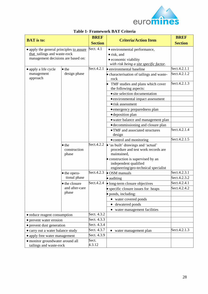
Within the context of the BREF on “Management of Tailings and Waste-Rock in Mining
Activities” and, in particular, of its Section 4 concerning “Techniques to consider in the
determination of BAT”, the criteria for BAT are summarized in Table 1.
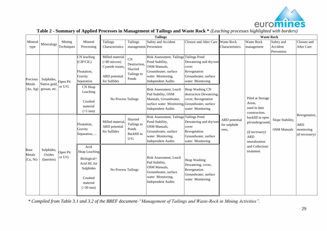
A summary of applied processes in management of tailings and waste rock for precious and base
metals mining, compiled from Table 3.1 and 3.2 in the BREF document is presented in Table 2.
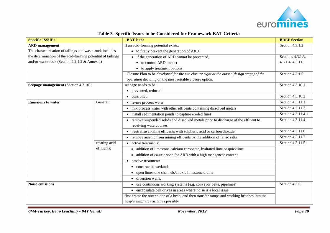
Specific issues of environmental concern, related to leach mining activities, that need to be taken
into consideration within the context of framework BAT criteria and their references to the BREF
on “Management of Tailings and Waste-Rock in Mining Activities are presented in Table 3.
28
Table 1- Framework BAT Criteria
BAT is to: BREF
Section Criteria/Action Item
BREF
Section
apply the general principles to assure
that tailings and waste-rock
management decisions are based on:
Sect. 4.1 environmental performance,
risk, and
economic viability with risk being a site specific factor.
apply a life cycle
management
approach
the
design phase
Sect.4.2.1 environmental baseline Sect.4.2.1.1
characterisation of tailings and waste-
rock
Sect.4.2.1.2
TMF studies and plans which cover
the following aspects:
Sect.4.2.1.3
site selection documentation
environmental impact assessment
risk assessment
emergency preparedness plan
deposition plan
water balance and management plan
decommissioning and closure plan
TMF and associated structures
design
Sect.4.2.1.4
control and monitoring Sect.4.2.1.5
the
construction
phase
Sect.4.2.2 „as built‟ drawings and „actual‟
procedure and test work records are
maintained,
construction is supervised by an
independent qualified
engineering/geo-technical specialist
the opera-
tional phase
Sect.4.2.3 OSM manuals Sect.4.2.3.1
auditing Sect.4.2.3.2
the closure
and after-care
phase
Sect.4.2.4 long-term closure objectives Sect.4.2.4.1
specific closure issues for heaps Sect.4.2.4.2
ponds, including:
water covered ponds
dewatered ponds
water management facilities
reduce reagent consumption Sect. 4.3.2
prevent water erosion Sect. 4.3.3
prevent dust generation Sect. 4.3.4
carry out a water balance study Sect. 4.3.7 water management plan Sect.4.2.1.3
apply free water management Sect. 4.3.9
monitor groundwater around all
tailings and waste-rock
Sect.
4.3.12
29
Table 2 - Summary of Applied Processes in Management of Tailings and Waste Rock * (Leaching processes highlighted with borders)
Mineral
type Mineralogy
Mining
Techniques
Mineral
Processing
Tailings Waste Rock
Tailings
Characteristics
Tailings
management
Safety and Accident
Prevention
Closure and After Care Waste Rock
Characteristics
Waste Rock
management
Safety and
Accident
Prevention
Closure and
After Care
Precious
Metals
(Au, Ag)
Sulphides,
Native gold,
gossan, etc.
Open Pit
or U/G
CN leaching
(CIP/CIL)
Floatation,
Gravity
Separation
Milled material
(<80 micron)
Cyanide issues,
ARD potential
for Sulfides
CN
Destruction,
Slurried
Tailings to
Ponds
Risk Assessment, Tailings
Pond Stability,
OSM Manuals,
Groundwater, surface
water Monitoring,
Independent Audits
Tailings Pond
Dewatering and dry/wet
cover
Revegetation
Groundwater, surface
water Monitoring
ARD potential
for sulphide
ores,
Piled at Storage
Areas,
used in dam
construction,
backfill in open
pit/underground,
(if necessary)
ARD
neuralization
and Collection/
treatment
Slope Stability,
OSM Manuals
Revegetation,
ARD
monitoring
(if necessary)
CN Heap
Leaching
Crushed
material
(>5 mm)
No Process Tailings
Risk Assessment, Leach
Pad Stability, OSM
Manuals, Groundwater,
surface water Monitoring,
Independent Audits
Heap Washing CN
destruction Dewatering,
cover, Revegetation
Groundwater, surface
water Monitoring
Base
Metals
(Cu, Ni)
Sulphides,
Oxides
(laterites)
Open Pit
or U/G
Floatation,
Gravity
Separation, ...
Milled material,
ARD potential
for Sulfides
Slurried
Tailings to
Ponds
Backfill in
U/G
Risk Assessment, Tailings
Pond Stability,
OSM Manuals,
Groundwater, surface
water Monitoring,
Independent Audits
Tailings Pond
Dewatering and dry/wet
cover
Revegetation
Groundwater, surface
water Monitoring
Acid
Heap Leaching
Biological+
Acid HL for
Sulphides
Crushed
material
(>30 mm)
No Process Tailings
Risk Assessment, Leach
Pad Stability,
OSM Manuals,
Groundwater, surface
water Monitoring,
Independent Audits
Heap Washing
Dewatering, cover,
Revegetation
Groundwater, surface
water Monitoring
* Compiled from Table 3.1 and 3.2 of the BREF document-“Management of Tailings and Waste-Rock in Mining Activities”.
GMA-Turkey, Heap Leaching – BAT (Final) November, 2012 Page 30
Table 3- Specific Issues to be Considered for Framework BAT Criteria
Specific ISSUE: BAT is to: BREF Section
ARD management
The characterisation of tailings and waste-rock includes
the determination of the acid-forming potential of tailings
and/or waste-rock (Section 4.2.1.2 & Annex 4)
If an acid-forming potential exists:
to firstly prevent the generation of ARD
Section 4.3.1.2
if the generation of ARD cannot be prevented,
to control ARD impact
to apply treatment options
Sections 4.3.1.3,
4.3.1.4, 4.3.1.6
Closure Plan to be developed for the site closure right at the outset (design stage) of the
operation deciding on the most suitable closure option.
Section 4.3.1.5
Seepage management (Section 4.3.10):
seepage needs to be:
prevented, reduced
Section 4.3.10.1
controlled Section 4.3.10.2
Emissions to water General: re-use process water Section 4.3.11.1
mix process water with other effluents containing dissolved metals Section 4.3.11.3
install sedimentation ponds to capture eroded fines Section 4.3.11.4.1
remove suspended solids and dissolved metals prior to discharge of the effluent to
receiving watercourses
Section 4.3.11.4
neutralise alkaline effluents with sulphuric acid or carbon dioxide Section 4.3.11.6
remove arsenic from mining effluents by the addition of ferric salts Section 4.3.11.7
treating acid
effluents:
active treatments: Section 4.3.11.5
addition of limestone calcium carbonate, hydrated lime or quicklime
addition of caustic soda for ARD with a high manganese content
passive treatment:
constructed wetlands
open limestone channels/anoxic limestone drains
diversion wells.
Noise emissions use continuous working systems (e.g. conveyor belts, pipelines) Section 4.3.5
encapsulate belt drives in areas where noise is a local issue
first create the outer slope of a heap, and then transfer ramps and working benches into the
heap‟s inner area as far as possible
GMA-Turkey, Heap Leaching – BAT (Final) November, 2012 Page 31
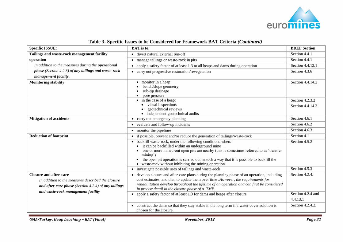
Table 3- Specific Issues to be Considered for Framework BAT Criteria (Continued)
Specific ISSUE: BAT is to: BREF Section
Tailings and waste-rock management facility
operation
In addition to the measures during the operational
phase (Section 4.2.3) of any tailings and waste-rock
management facility,
divert natural external run-off Section 4.4.1
manage tailings or waste-rock in pits Section 4.4.1
apply a safety factor of at least 1.3 to all heaps and dams during operation Section 4.4.13.1
carry out progressive restoration/revegetation Section 4.3.6
Monitoring stability monitor in a heap bench/slope geometry sub-tip drainage pore pressure
Section 4.4.14.2
in the case of a heap: visual inspections geotechnical reviews independent geotechnical audits
Section 4.2.3.2
Section 4.4.14.3
Mitigation of accidents carry out emergency planning Section 4.6.1
evaluate and follow-up incidents Section 4.6.2
monitor the pipelines Section 4.6.3
Reduction of footprint
if possible, prevent and/or reduce the generation of tailings/waste-rock Section 4.1
backfill waste-rock, under the following conditions when: it can be backfilled within an underground mine one or more mined-out open pits are nearby (this is sometimes referred to as „transfer
mining‟) the open pit operation is carried out in such a way that it is possible to backfill the waste-rock without inhibiting the mining operation
Section 4.5.2
investigate possible uses of tailings and waste-rock Section 4.5.3
Closure and after-care
In addition to the measures described the closure
and after-care phase (Section 4.2.4) of any tailings
and waste-rock management facility
develop closure and after-care plans during the planning phase of an operation, including
cost estimates, and then to update them over time .However, the requirements for
rehabilitation develop throughout the lifetime of an operation and can first be considered
in precise detail in the closure phase of a TMF
Section 4.2.4.
apply a safety factor of at least 1.3 for dams and heaps after closure Section 4.2.4 and
4.4.13.1
construct the dams so that they stay stable in the long term if a water cover solution is
chosen for the closure.
Section 4.2.4.2.
GMA-Turkey, Heap Leaching – BAT (Final) November, 2012 Page 32
© Caner Zanbak, PhD
9. CONCLUSIONS
In response to ever increasing prices of base metals like copper, nickel, cobalt and precious
metals, heap leaching has become a major beneficiation technique used for large tonnage-low
grade ores which cannot be economically processed through tank leaching or any other
available techniques.
The heap leaching process has been successfully applied to very low grade base metal (copper,
zinc, nickel and cobalt) and precious metal (gold and silver) ores since 1969. Techniques
developed in the world during the last several decades demonstrated that heap leaching is a
viable process that can be applied in a manner:
to address all of the regulatory issues identified in the BREF on “Management of
Tailings and Waste-Rock in Mining Activities” (Table 1 and Table 3) and,
to ensure a high level of protection for the environment as a whole within the context of Best
Available Techniques (BATs).
GMA-Turkey, Heap Leaching – BAT (Final) November, 2012 Page 33
© Caner Zanbak, PhD
10. REFERENCES CITED
Breitenbach, A.J., Thiel, R.S. (2005), A Tale of Two Conditions: Heap Leach Pad Versus
Landfill Liner Strengths, NAGS-GSI/GRI-19 Geosynthetics Conference, Las Vegas,
Nevada, USA, Dec.
Breitenbach, A.J., Smith, M.E., (2006), Overview of Geomembrane History and Design
Practices in the Mining Industry, IGS-8th Int. Conference on Geosynthetics, Yokohama,
Japan, Sept.
Brittan, M.I. (2008), Kinetic and Equilibrium Effects in Gold Ore Cyanidation, Minerals &
Metallurgical Processing, Vol. 25, No. 3, pp117-122.
Habashi, F., (2005), A Short History of Hydrometallurgy, Hydrometallurgy, Elsevier BV,
pp15–22, doi:10.1016/j.hydromet.2004.01.008.
Kappes, D.W. (2002), Precious Metal Heap Leach Design and Practice, in Proc. Mineral
Processing Plant design, Practice and Control, SME, Colorado, USA, ISBN 0-87335-223-8,
Vol.2, pp 1606-1630.
Lewandowski, K.A., Kawatra, S.K., (2009), Binders for Heap Leaching Agglomeration,
Minerals & Metall. Process. Journal, SME, Littleton, Colorado, USA, Volume 26, No. 1.
Marsden, J., House, I. (2006), The Chemistry of Gold Extraction, SME Publication, Littleton,
Colorado, USA, (2nd edition), ISBN-13: 978-0-87335-240-6.
Marsden, J.O. (2009), Lessons Learned from the Copper Industry Applied to Gold Extraction,
Keynote Presentation - World Gold 2009 Conference, Johannesburg, South Africa, October
McNab, B. (2006), Exploring HPGR Technology For Heap Leaching of Fresh Rock Gold
Ores, IIR Crushing & Grinding Conference, Townsville, Australia, March 29–30.
Robertson, SW, Vercuil, A., van Staden, PJ, Craven, P., 2005, A Bacterial Heap Leaching
Approach for the Treatment of Low Grade Primary Copper Sulphide Ore, 3rd S. African
Conf. on Base Metals,SAIMM Symp. Series S39, ISBN 1–919783–74–1, pp 471-484.
Seed, H. B. 1979. 19th Rankine Lecture: Considerations in the Earthquake Design of Earth and
Rockfill Dams,” Geotechnique, Vol 29, No. 3, pp 215-263.
Thiel, R.S., Smith, M.E., (2003), State Of The Practice Review of Heap Leach Pad Design
Issues, Proc. GRI-18, Las Vegas, Nevada, USA, vol. 22, pp. 555 - 568, Dec.
Related Documents