SERVICE MANUAL Sony Corporation Audio&Video Business Group Published by Sony Techno Create Corporation SPECIFICATIONS DVD RECEIVER 9-889-099-02 2008G04-1 © 2008.07 AEP Model UK Model HCD-DZ860W E Model HCD-DZ870KW/DZ870W Australian Model HCD-DZ870W Russian Model HCD-DZ870M Ver. 1.1 2008.07 Model Name Using Similar Mechanism HCD-DZ260/DZ270/HDZ278 Mechanism Type CDM85-DVBU102 Optical Pick-up Name KHM-313CAA • HCD-DZ860W/DZ870KW/DZ870M/DZ870W are the amplifier, DVD/CD and tuner section in DAV-DZ860W/DZ870KW/DZ870M/DZ870W. Photo : HCD-DZ870KW This system incorporates with Dolby* Digital and Dolby Pro Logic (II) adaptive matrix surround decoder and the DTS** Digital Surround System. * Manufactured under license from Dolby Laboratories. “Dolby”, “Pro Logic”, and the double-D symbol are trademarks of Dolby Laboratories. ** Manufactured under license from DTS, Inc. “DTS” and “DTS Digital Surround” are registered trademarks of DTS, Inc. Amplifier Section (DZ860W/DZ870KW) Stereo mode (rated) 108 W + 108 W (at 3 ohms, 1 kHz, 1% THD) Surround mode (reference) RMS output power FL/FR/C*: 143 watts (per channel at 3 ohms, 1 kHz, 10% THD) Subwoofer*: 285 watts (at 1.5 ohms, 80 Hz, 10% THD) Amplifier Section (DZ870M) Stereo mode (rated) 108 W + 108 W (at 3 ohms, 1 kHz, 1% THD) Surround mode (reference) RMS output power FL/FR/C/SL/SR*: 143 watts (per channel at 3 ohms, 1 kHz, 10% THD) Subwoofer*: 285 watts (at 1.5 ohms, 80 Hz, 10% THD) Amplifier Section (DZ870W) Latin American models: Stereo mode (rated) 108 W + 108 W (at 3 ohms, 1 kHz, 1% THD) Surround mode (reference) RMS output power FL/FR/C*: 142 watts (per channel at 3 ohms, 1 kHz, 10% THD) Subwoofer*: 284 watts (at 1.5 ohms, 80 Hz, 10% THD) Other models: Stereo mode (rated) 108 W + 108 W (at 3 ohms, 1 kHz, 1% THD) Surround mode (reference) RMS output power FL/FR/C*: 143 watts (per channel at 3 ohms, 1 kHz, 10% THD) Subwoofer*: 285 watts (at 1.5 ohms, 80 Hz, 10% THD) * Depending on the decoding mode settings and the source, there may be no sound output. Inputs (Analog) (DZ860W) TV (AUDIO IN) Sensitivity: 450/250 mV LINE(AUDIO IN) Sensitivity: 450/250 mV AUDIO IN Sensitivity: 250/125 mV Inputs (Analog) (DZ870KW/DZ870M) TV (AUDIO IN) Sensitivity: 450/250 mV SAT/CABLE (AUDIO IN) Sensitivity: 450/250 mV AUDIO IN/MIC1 Sensitivity: AUDIO IN 250/125 mV/MIC1 1 mV MIC2 Sensitivity: 1 mV Inputs (Analog) (DZ870W) TV (AUDIO IN) Sensitivity: 450/250 mV SAT/CABLE (AUDIO IN) Sensitivity: 450/250 mV AUDIO IN Sensitivity: 250/125 mV Inputs (Digital) (DZ860W/DZ870KW/DZ870M/ DZ870W) TV (COAXIAL IN/OPTICAL IN) Impedance: 75 ohms/- Outputs (Analog) (DZ860W/DZ870W) Phones Accepts low- and high- impedance headphones. Super Audio CD/DVD System Laser Semiconductor laser (Super Audio CD/DVD: λ = 650 nm) (CD: λ = 790 nm) Emission duration: continuous Signal format system Mexican and Latin American models: NTSC Other models: PAL/NTSC USB Section Supported bit rate MP3 (MPEG 1 Audio Layer-3): 32 kbps - 320 kbps WMA: 48 kbps - 192 kbps AAC: 48 kbps - 320 kbps Sampling frequencies MP3 (MPEG 1 Audio Layer-3): 32/44.1/48 kHz WMA: 44.1 kHz AAC: 44.1 kHz (USB) port: Maximum current: 500 mA – Continued on next page – HCD-DZ860W/DZ870KW/ DZ870M/DZ870W

HCD-DZ860W_ver1.1
Oct 30, 2014
Welcome message from author
This document is posted to help you gain knowledge. Please leave a comment to let me know what you think about it! Share it to your friends and learn new things together.
Transcript
SERVICE MANUAL
Sony CorporationAudio&Video Business GroupPublished by Sony Techno Create Corporation
SPECIFICATIONS
DVD RECEIVER9-889-099-022008G04-1© 2008.07
AEP ModelUK Model
HCD-DZ860W
E ModelHCD-DZ870KW/DZ870W
Australian ModelHCD-DZ870W
Russian ModelHCD-DZ870M
Ver. 1.1 2008.07
Model Name Using Similar Mechanism HCD-DZ260/DZ270/HDZ278Mechanism Type CDM85-DVBU102Optical Pick-up Name KHM-313CAA
• HCD-DZ860W/DZ870KW/DZ870M/DZ870W are the amplifi er, DVD/CD and tuner section in DAV-DZ860W/DZ870KW/DZ870M/DZ870W.
Photo : HCD-DZ870KW
This system incorporates with Dolby* Digital and Dolby Pro Logic (II) adaptive matrix surround decoder and the DTS** Digital Surround System.* Manufactured under license from Dolby Laboratories. “Dolby”, “Pro Logic”, and the double-D symbol are trademarks
of Dolby Laboratories.** Manufactured under license from DTS, Inc. “DTS” and “DTS Digital Surround” are registered trademarks
of DTS, Inc.
Amplifi er Section (DZ860W/DZ870KW)Stereo mode (rated) 108 W + 108 W (at 3 ohms, 1 kHz, 1% THD)Surround mode (reference) RMS output power FL/FR/C*: 143 watts (per channel at 3 ohms, 1 kHz, 10% THD) Subwoofer*: 285 watts (at 1.5 ohms, 80 Hz, 10% THD)
Amplifi er Section (DZ870M)Stereo mode (rated) 108 W + 108 W (at 3 ohms, 1 kHz, 1% THD)Surround mode (reference) RMS output power FL/FR/C/SL/SR*: 143 watts (per channel at 3 ohms, 1 kHz, 10% THD) Subwoofer*: 285 watts (at 1.5 ohms, 80 Hz, 10% THD)
Amplifi er Section (DZ870W)Latin American models:Stereo mode (rated) 108 W + 108 W (at 3 ohms, 1 kHz, 1% THD)Surround mode (reference) RMS output power FL/FR/C*: 142 watts (per channel at 3 ohms, 1 kHz, 10% THD) Subwoofer*: 284 watts (at 1.5 ohms, 80 Hz, 10% THD)
Other models:Stereo mode (rated) 108 W + 108 W (at 3 ohms, 1 kHz, 1% THD)Surround mode (reference) RMS output power FL/FR/C*: 143 watts (per channel at 3 ohms, 1 kHz, 10% THD) Subwoofer*: 285 watts (at 1.5 ohms, 80 Hz, 10% THD)
* Depending on the decoding mode settings and the source, there may be no sound output.
Inputs (Analog) (DZ860W)TV (AUDIO IN) Sensitivity: 450/250 mVLINE(AUDIO IN) Sensitivity: 450/250 mVAUDIO IN Sensitivity: 250/125 mVInputs (Analog) (DZ870KW/DZ870M)TV (AUDIO IN) Sensitivity: 450/250 mVSAT/CABLE (AUDIO IN) Sensitivity: 450/250 mVAUDIO IN/MIC1 Sensitivity: AUDIO IN 250/125 mV/MIC1 1 mVMIC2 Sensitivity: 1 mVInputs (Analog) (DZ870W)TV (AUDIO IN) Sensitivity: 450/250 mVSAT/CABLE (AUDIO IN) Sensitivity: 450/250 mVAUDIO IN Sensitivity: 250/125 mVInputs (Digital) (DZ860W/DZ870KW/DZ870M/DZ870W)TV (COAXIAL IN/OPTICAL IN) Impedance: 75 ohms/-Outputs (Analog) (DZ860W/DZ870W)Phones Accepts low- and high- impedance headphones.
Super Audio CD/DVD SystemLaser Semiconductor laser (Super Audio CD/DVD: λ = 650 nm) (CD: λ = 790 nm) Emission duration: continuousSignal format systemMexican and Latin American models: NTSCOther models: PAL/NTSC
USB SectionSupported bit rateMP3 (MPEG 1 Audio Layer-3): 32 kbps - 320 kbpsWMA: 48 kbps - 192 kbpsAAC: 48 kbps - 320 kbpsSampling frequenciesMP3 (MPEG 1 Audio Layer-3): 32/44.1/48 kHzWMA: 44.1 kHzAAC: 44.1 kHz
(USB) port:Maximum current: 500 mA
– Continued on next page –
HCD-DZ860W/DZ870KW/DZ870M/DZ870W
HCD-DZ860W/DZ870KW/DZ870M/DZ870W
2
SAFETY-RELATED COMPONET WARNING!
COMPONENTS IDENTIFIED BY MARK 0 OR DOTTED LINE WITH MARK 0 ON THE SCHEMATIC DIAGRAMS AND IN THE PARTS LIST ARE CRITICAL TO SAFE OPERATION.REPLACE THESE COMPONENTS WITH SONY PARTS WHOSE PART NUMBERS APPEAR AS SHOWN IN THIS MANUAL OR IN SUPPLEMENTS PUBLISHED BY SONY.
Tuner SectionSystem PLL quartz-locked digital synthesizerFM tuner sectionTuning range 87.5 MHz - 108.0 MHz (50 kHz step)Antenna (aerial) FM wire antenna (aerial)Antenna (aerial) terminals 75 ohms, unbalancedIntermediate frequency 10.7 MHzAM tuner sectionTuning rangeMexican, and Latin American models: 530 kHz - 1,710 kHz (with the interval set at 10 kHz) 531 kHz - 1,710 kHz (with the interval set at 9 kHz)European, Russian, and Middle Eastern models: 531 kHz - 1,602 kHz (with the interval set at 9 kHz)Australian and New Zealand models: 531 kHz - 1,710 kHz (with the interval set at 9 kHz) 530 kHz - 1,710 kHz (with the interval set at 10 kHz)Other models: 531 kHz - 1,602 kHz (with the interval set at 9 kHz) 530 kHz - 1,610 kHz (with the interval set at 10 kHz)Antenna (aerial) AM loop antenna (aerial)Intermediate frequency 450 kHz
Video Section (DZ860W)Outputs VIDEO: 1 Vp-p 75 ohms R/G/B: 0.7 Vp-p 75 ohms HDMI OUT: Type A (19 pin)
Video Section (DZ870KW/DZ870M/DZ870W)Outputs VIDEO: 1 Vp-p 75 ohms COMPONENT: Y: 1 Vp-p 75 ohms PB/CB, PR/CR: 0.7 Vp-p 75 ohms HDMI OUT: Type A (19 pin)
GeneralPower requirementsMexican models: 120 V AC, 60 HzTaiwan models: 120 V AC, 50/60 HzLatin American models: 110 V - 240 V AC, 50/60 HzOther models: 220 V - 240 V AC, 50/60 HzPower consumptionHCD-DZ870M: On: 160 W Standby: 0.3 W (at the Power Saving mode)HCD-DZ860W/DZ870KW/DZ870W: On: 130 W Standby: 0.3 W (at the Power Saving mode)Output voltage (DIGITAL MEDIA PORT) DC 5 VOutput current (DIGITAL MEDIA PORT) 700 mADimensions (approx.) 430 mm × 66 mm × 385 mm (w/h/d) incl. projecting partsHCD-DZ860W/DZ870KW/DZ870W: 430 mm × 66 mm × 415 mm (w/h/d) with the wireless transceiver insertedMass (approx.) 4.3 kg
Design and specifi cations are subject to changewithout notice.
Special Component NoticeThe components identifi ed by mark 9 contain confi dential infor-mation.Strictly follow the instructions whenever the components are re-paired and/or replaced.
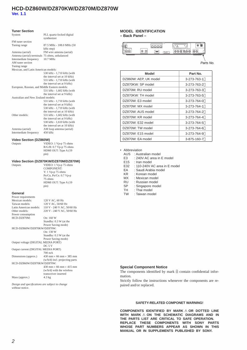
• Abbreviation AUS : Australian model E3 : 240V AC area in E model E15 : Iran model E32 : 110-240V AC area in E model EA : Saudi Arabia model KR : Korean model MX : Mexican model RU : Russian model SP : Singapore model TH : Thai model TW : Taiwan model
Model Part No.DZ860W: AEP, UK model 3-273-763-1[]
DZ870KW: SP model 3-273-763-2[]
DZ870M: RU model 3-273-763-3[]
DZ870KW: TH model 3-273-763-5[]
DZ870W: E3 model 3-273-764-0[]
DZ870W: MX model 3-273-764-1[]
DZ870W: AUS model 3-273-764-2[]
DZ870W: KR model 3-273-764-4[]
DZ870W: E32 model 3-273-764-5[]
DZ870W: TW model 3-273-764-6[]
DZ870W: E15 model 3-273-764-9[]
DZ870W: EA model 3-875-160-7[]
MODEL IDENTIFICATION– Back Panel –
Parts No.
Ver. 1.1
HCD-DZ860W/DZ870KW/DZ870M/DZ870W
3
UNLEADED SOLDERBoards requiring use of unleaded solder are printed with the lead-free mark (LF) indicating the solder contains no lead.(Caution: Some printed circuit boards may not come printed with
the lead free mark due to their particular size)
: LEAD FREE MARKUnleaded solder has the following characteristics.• Unleaded solder melts at a temperature about 40 °C higher
than ordinary solder. Ordinary soldering irons can be used but the iron tip has to be
applied to the solder joint for a slightly longer time. Soldering irons using a temperature regulator should be set to
about 350 °C.Caution: The printed pattern (copper foil) may peel away if the
heated tip is applied for too long, so be careful!• Strong viscosity Unleaded solder is more viscous (sticky, less prone to fl ow)
than ordinary solder so use caution not to let solder bridges occur such as on IC pins, etc.
• Usable with ordinary solder It is best to use only unleaded solder but unleaded solder may
also be added to ordinary solder.
Notes on chip component replacement• Never reuse a disconnected chip component.• Notice that the minus side of a tantalum capacitor may be dam-
aged by heat.
Flexible Circuit Board Repairing• Keep the temperature of soldering iron around 270 °C during
repairing.• Do not touch the soldering iron on the same conductor of the
circuit board (within 3 times).• Be careful not to apply force on the conductor when soldering
or unsoldering.
Laser component in this product is capable of emitting radiation exceed-ing the limit for Class 1.
This appliance is classifi ed as a CLASS 1 LASER product.This marking is located on the rear or bottom exterior.
CAUTIONUse of controls or adjustments or performance of procedures other than those specifi ed herein may result in hazardous radiation exposure.
About This OperatingInstructions• The instructions in this Operating Instructions
describe the controls on the remote. You canalso use the controls on the unit if they have thesame or similar names as those on the remote.
• The Control Menu items may vary dependingon the area.
• “DVD” may be used as a general term for aDVD VIDEO, DVD+RW/DVD+R, and DVD-RW/DVD-R.
• Measurements are expressed in feet (ft) forNorth American models.
• The default setting is underlined.
About the S-AIR functionThe system is compatible with the S-AIRfunction, which allows transmission of soundbetween S-AIR products wirelessly.The following S-AIR products can be used withthe system:
• Surround amplifier (supplied): You can enjoysurround speaker sound wirelessly.
• S-AIR receiver (optional): You can enjoysystem sound in another room.
The S-AIR receiver can be purchased as anoption (the S-AIR product lineup differsdepending on the area).
Notes or instructions for the surround amplifieror S-AIR receiver in this operating instructionsrefer only to when the surround amplifier orS-AIR receiver is used.For details on the S-AIR function, see “Using anS-AIR Product” (page 81).
HCD-DZ860W/DZ870KW/DZ870M/DZ870W
4
5GB
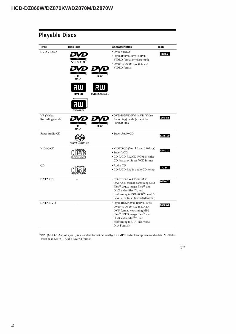
Playable Discs
1)MP3 (MPEG1 Audio Layer 3) is a standard format defined by ISO/MPEG which compresses audio data. MP3 filesmust be in MPEG1 Audio Layer 3 format.
nocIscitsiretcarahCogolcsiDepyT
OEDIVDVD•OEDIVDVD• DVD-R/DVD-RW in DVD
VIDEO format or video mode• DVD+R/DVD+RW in DVD
VIDEO format
VR (VideoRecording) mode
• DVD-R/DVD-RW in VR (VideoRecording) mode (except forDVD-R DL)
DCoiduArepuS•DCoiduArepuS
)scsid0.2dna1.1.reV(DCOEDIV•DCOEDIV• Super VCD• CD-R/CD-RW/CD-ROM in video
CD format or Super VCD format
DCoiduA•DC• CD-R/CD-RW in audio CD format
niMOR-DC/WR-DC/R-DC•–DCATADDATA CD format, containing MP3files1), JPEG image files2), andDivX video files3)4), andconforming to ISO 96605) Level 1/Level 2, or Joliet (extended format)
/WR-DVD/R-DVD/MOR-DVD•–DVDATADDVD+R/DVD+RW in DATADVD format, containing MP3files1), JPEG image files2), andDivX video files3)4), andconforming to UDF (UniversalDisk Format)
HCD-DZ860W/DZ870KW/DZ870M/DZ870W
5
6GB
2)JPEG image files must conform to the DCF image file format. (DCF “Design rule for Camera File system”: Imagestandards for digital cameras regulated by Japan Electronics and Information Technology Industries Association(JEITA).)
3) DivX® is a video file compression technology, developed by DivX, Inc.4) DivX, DivX Certified, and associated logos are trademarks of DivX, Inc. and are used under license.5)A logical format of files and folders on CD-ROMs, defined by ISO (International Organization for
Standardization).“DVD-RW,” “DVD+RW,” “DVD+R,”“DVD VIDEO,” and the “CD” logos are trademarks.
The system cannot play the following discs:• CD-ROM/CD-R/CD-RW other than those recorded in the formats listed on page 5• CD-ROM recorded in PHOTO CD format• Data part of CD-Extra• CD Graphics disc• DVD Audio• DATA DVD that does not contain MP3 files, JPEG image files, or DivX video files• DVD-RAM
Also, the system cannot play the following discs:• A DVD VIDEO with a different region code (page 7)• A disc that has a non-standard shape (e.g., card, heart)• A disc with paper or stickers on it• A disc that has the adhesive of cellophane tape or a sticker still left on it
In some cases, CD-R/CD-RW/DVD-R/DVD-RW/DVD+R/DVD+RW cannot be played on this systemdue to the recording quality or physical condition of the disc, or the characteristics of the recordingdevice and authoring software.The disc will not play if it has not been correctly finalized. For more information, refer to the operatinginstructions for the recording device.Note that some playback functions may not work with some DVD+RWs/DVD+Rs, even if they havebeen correctly finalized. In this case, view the disc by normal playback. Also some DATA CDs/DATADVDs created in Packet Write format cannot be played.
Music discs encoded with copyright protection technologiesThis product is designed to play back discs that conform to the Compact Disc (CD) standard.Recently, various music discs encoded with copyright protection technologies are marketed by somerecord companies. Please be aware that among those discs, there are some that do not conform to theCD standard and may not be playable by this product.
Note on DualDiscsA DualDisc is a two sided disc product which mates DVD recorded material on one side with digitalaudio material on the other side. However, since the audio material side does not conform to theCompact Disc (CD) standard, playback on this product is not guaranteed.
Example of discs that the system cannot play
Note about CD-R/CD-RW/DVD-R/DVD-RW/DVD+R/DVD+RW
HCD-DZ860W/DZ870KW/DZ870M/DZ870W
6
7GB
• This system can play a Multi Session CD when an MP3 file is contained in the first session. Anysubsequent MP3 files recorded in later sessions can also be played back.
• This system can play a Multi Session CD when a JPEG image file is contained in the first session.Any subsequent JPEG image files recorded in later sessions can also be played back.
• If MP3 files and JPEG image files in music CD format or video CD format are recorded in the firstsession, only the first session will be played back.
Your system has a region code printed on the rear of the unit and will only play a DVD labeled withthe same region code.
A DVD VIDEO labeled will also play on this system.If you try to play any other DVD VIDEO, the message [Playback prohibited by area limitations.] willappear on the TV screen. Depending on the DVD VIDEO, no region code indication may be given eventhough playing the DVD VIDEO is prohibited by area restrictions.
Some playback operations on a DVD or VIDEO CD may be intentionally set by software producers.Since this system will play a DVD or VIDEO CD according to the disc contents the software producersdesigned, some playback features may not be available. Be sure to read the operating instructionssupplied with the DVD or VIDEO CD.
This product incorporates copyright protection technology that is protected by U.S. patents and otherintellectual property rights. Use of this copyright protection technology must be authorized byMacrovision, and is intended for home and other limited viewing uses only unless otherwise authorizedby Macrovision. Reverse engineering or disassembly is prohibited.
This system incorporates with Dolby* Digital and Dolby Pro Logic (II) adaptive matrix surrounddecoder and the DTS** Digital Surround System.
* Manufactured under license from Dolby Laboratories.“Dolby”, “Pro Logic”, and the double-D symbol are trademarks of Dolby Laboratories.
** Manufactured under license from DTS, Inc.“DTS” and “DTS Digital Surround” are registered trademarks of DTS, Inc.
This system incorporates High-Definition Multimedia Interface (HDMITM) technology.HDMI, the HDMI logo and High-Definition Multimedia Interface are trademarks or registeredtrademarks of HDMI Licensing LLC.
“BRAVIA” and are trademarks of Sony Corporation.
“S-AIR” and its logo are trademarks of Sony Corporation.
About Multi Session CD
Region code
Note about playback operations of a DVD or VIDEO CD
Copyrights
ALL

HCD-DZ860W/DZ870KW/DZ870M/DZ870W
7
108 GB
Self-diagnosis Function(When letters/numbers appear in thedisplay)
When the self-diagnosis function is activated toprevent the system from malfunctioning, a 5-character service number (e.g., C 13 50) with acombination of a letter and 4 digits appears onthe TV screen or front panel display. In this case,check the following table.
When displaying the versionnumber on the TV screenWhen you turn on the system, the versionnumber [VER.X.XX] (X is a number) mayappear on the TV screen. Although this is not amalfunction and for Sony service use only,normal system operation will not be possible.Turn off the system, and then turn on the systemagain to operate.
First 3characters ofthe servicenumber
Cause and/or corrective action
C 13 The disc is dirty.Clean the disc with a soft cloth(page 97).
C 31 The disc is not inserted correctly.Restart the system, then re-insertthe disc correctly.
E XX(XX is anumber)
To prevent a malfunction, thesystem has performed the self-diagnosis function.
Contact your nearest Sonydealer or local authorized Sonyservice facility and give the 5-character service number.Example: E 61 10
C:13:50
VER.X.XX
HCD-DZ860W/DZ870KW/DZ870M/DZ870W
8
1. SERVICING NOTES ............................................. 9
2. GENERAL .................................................................. 11
3. DISASSEMBLY3-1. Case ................................................................................ 243-2. POWER Board (DZ860W/DZ870W) ............................. 243-3. Front Panel Section (DZ860W/DZ870W) ...................... 253-4. POWER Board (DZ870KW/DZ870M) .......................... 253-5. Front Panel Section (DZ870KW/DZ870M) ................... 263-6. Back Panel Section (DZ870M) ....................................... 263-7. Back Panel Section (Except DZ870M) ........................... 273-8. DVD Mechanism Deck ................................................... 273-9. MAIN Board ................................................................... 283-10. IO-SCART Board (DZ860W), IO-COMPONENT Board (Except DZ860W), SCORE Board (DZ870KW/DZ870M) ........................... 283-11. Tray ................................................................................. 293-12. Belt .................................................................................. 293-13. MS-203 Board ................................................................. 303-14. Base Unit ......................................................................... 303-15. Optical Pick-up ............................................................... 31
4. TEST MODE ............................................................ 32
5. ELECTRICAL ADJUSTMENTS ........................ 37
6. DIAGRAMS6-1. Block Diagram –RF Section– ......................................... 416-2. Block Diagram –VIDEO Section– ................................. 426-3. Block Diagram –AUDIO Section– ................................. 436-4. Block Diagram –DSP Section– ....................................... 446-5. Block Diagram –AMP Section– ..................................... 456-6. Block Diagram –POWER Section– ................................ 466-7. Printed Wiring Board –MAIN Board (Side A)– ............. 476-8. Printed Wiring Board –MAIN Board (Side B)– ............. 486-9. Schematic Diagram –MAIN Board (1/9)– ...................... 496-10. Schematic Diagram –MAIN Board (2/9)– ...................... 506-11. Schematic Diagram –MAIN Board (3/9)– ...................... 516-12. Schematic Diagram –MAIN Board (4/9), MS-203 Board– ............................................................... 526-13. Schematic Diagram –MAIN Board (5/9)– ...................... 53
TABLE OF CONTENTS
6-14. Schematic Diagram –MAIN Board (6/9)– ...................... 546-15. Schematic Diagram –MAIN Board (7/9)– ...................... 556-16. Schematic Diagram –MAIN Board (8/9)– ...................... 566-17. Schematic Diagram –MAIN Board (9/9)– ...................... 576-18. Printed Wiring Board –IO-SCART Board (DZ860W)– .. 586-19. Schematic Diagram –IO-SCART Board (DZ860W)– ..... 596-20. Printed Wiring Board –IO-COMPONENT Board (DZ870KW/DZ870M/DZ870W)– .................................. 606-21. Schematic Diagram –IO-COMPONENT Board (DZ870KW/DZ870M/DZ870W)– .................................. 616-22. Printed Wiring Boards –JACK, P-SW Board– ............... 626-23. Schematic Diagram –JACK, P-SW Board– .................... 636-24. Printed Wiring Boards –FL, MS-203, SPEAKER Board– .................................. 646-25. Schematic Diagram –FL, SPEAKER Board– ................. 656-26. Printed Wiring Board –DSP Board (Side A)– ................. 666-27. Printed Wiring Board –DSP Board (Side B)– ................. 676-28. Schematic Diagram –DSP Board– .................................. 686-29. Printed Wiring Board –S-AIR-INC Board (Side A) (DZ860W/DZ870KW/DZ870W)– ................................. 696-30. Printed Wiring Board –S-AIR-INC Board (Side B) (DZ860W/DZ870KW/DZ870W)– ................................. 706-31. Schematic Diagram –S-AIR-INC Board (DZ860W/DZ870KW/DZ870W)– ................................. 716-32. Printed Wiring Board –S-AIR-CON Board (DZ870M)– .. 726-33. Schematic Diagram –S-AIR-CON Board (DZ870M)– ..... 736-34. Printed Wiring Board –SERIPARA (DSR) Board– ........ 746-35. Schematic Diagram –SERIPARA (DSR) Board– ........... 756-36. Printed Wiring Board –SCORE Board (DZ870KW/DZ870M)– .................................................. 766-37. Schematic Diagram –SCORE Board (DZ870KW/DZ870M)– .................................................. 776-38. Printed Wiring Board –POWER Board– ........................ 786-39. Schematic Diagram –POWER Board– ........................... 79
7. EXPLODED VIEWS7-1. Overall Section ............................................................... 977-2. Front Panel Section ......................................................... 987-3. Chassis Section ............................................................... 997-4. DVD Mechanism Deck Section (CDM85-DVBU102) .. 100
8. ELECTRICAL PARTS LIST .............................. 101
HCD-DZ860W/DZ870KW/DZ870M/DZ870W
9
SECTION 1SERVICING NOTES
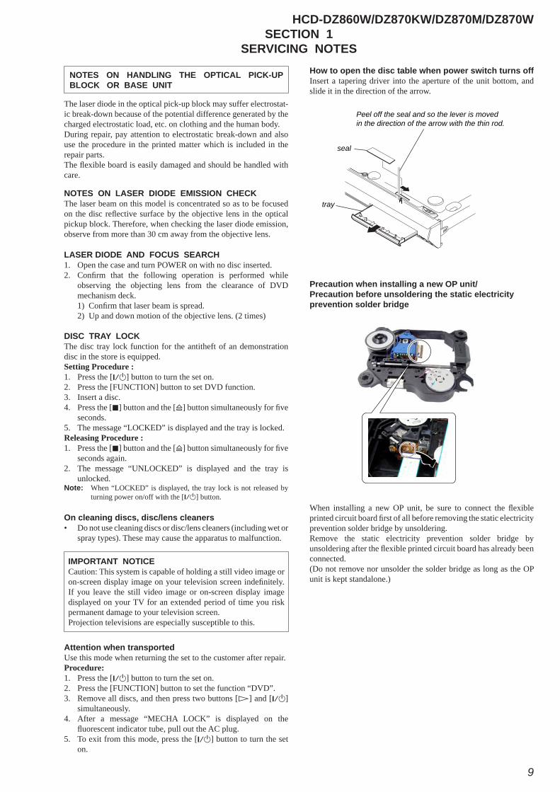
How to open the disc table when power switch turns off Insert a tapering driver into the aperture of the unit bottom, and slide it in the direction of the arrow.
Precaution when installing a new OP unit/ Precaution before unsoldering the static electricity prevention solder bridge
When installing a new OP unit, be sure to connect the fl exible printed circuit board fi rst of all before removing the static electricity prevention solder bridge by unsoldering. Remove the static electricity prevention solder bridge by unsoldering after the fl exible printed circuit board has already been connected. (Do not remove nor unsolder the solder bridge as long as the OP unit is kept standalone.)
Peel off the seal and so the lever is moved in the direction of the arrow with the thin rod.
tray
seal
NOTES ON HANDLING THE OPTICAL PICK-UP BLOCK OR BASE UNIT
The laser diode in the optical pick-up block may suffer electrostat-ic break-down because of the potential difference generated by the charged electrostatic load, etc. on clothing and the human body.During repair, pay attention to electrostatic break-down and also use the procedure in the printed matter which is included in the repair parts.The fl exible board is easily damaged and should be handled with care.
NOTES ON LASER DIODE EMISSION CHECKThe laser beam on this model is concentrated so as to be focused on the disc refl ective surface by the objective lens in the optical pickup block. Therefore, when checking the laser diode emission, observe from more than 30 cm away from the objective lens.
DISC TRAY LOCKThe disc tray lock function for the antitheft of an demonstrationdisc in the store is equipped.Setting Procedure :1. Press the [?/1] button to turn the set on.2. Press the [FUNCTION] button to set DVD function.3. Insert a disc.4. Press the [x] button and the [A] button simultaneously for fi ve
seconds.5. The message “LOCKED” is displayed and the tray is locked.Releasing Procedure :1. Press the [x] button and the [A] button simultaneously for fi ve
seconds again.2. The message “UNLOCKED” is displayed and the tray is
unlocked.Note: When “LOCKED” is displayed, the tray lock is not released by
turning power on/off with the [?/1] button.
On cleaning discs, disc/lens cleaners• Do not use cleaning discs or disc/lens cleaners (including wet or
spray types). These may cause the apparatus to malfunction.
IMPORTANT NOTICECaution: This system is capable of holding a still video image or on-screen display image on your television screen indefi nitely. If you leave the still video image or on-screen display image displayed on your TV for an extended period of time you risk permanent damage to your television screen.Projection televisions are especially susceptible to this.
Attention when transportedUse this mode when returning the set to the customer after repair.Procedure:1. Press the [?/1] button to turn the set on.2. Press the [FUNCTION] button to set the function “DVD”.3. Remove all discs, and then press two buttons [H] and [?/1]
simultaneously.4. After a message “MECHA LOCK” is displayed on the
fl uorescent indicator tube, pull out the AC plug.5. To exit from this mode, press the [?/1] button to turn the set
on.
LASER DIODE AND FOCUS SEARCH1. Open the case and turn POWER on with no disc inserted.2. Confi rm that the following operation is performed while
observing the objecting lens from the clearance of DVD mechanism deck.1) Confi rm that laser beam is spread.2) Up and down motion of the objective lens. (2 times)
HCD-DZ860W/DZ870KW/DZ870M/DZ870W
10
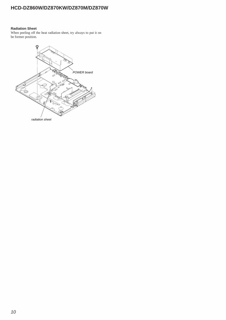
Radiation SheetWhen peeling off the heat radiation sheet, try always to put it on be former position.
radiation sheet
POWER board
HCD-DZ860W/DZ870KW/DZ870M/DZ870W
11
SECTION 2GENERAL This section is extracted
from instruction manual.
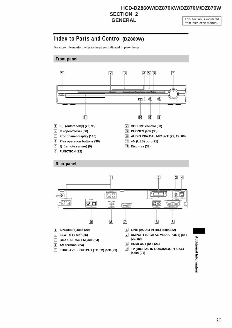
Index to Parts and Control (DZ860W)For more information, refer to the pages indicated in parentheses.
/ (on/standby) (29, 95)(open/close) (38)
Front panel display (116)Play operation buttons (38)
(remote sensor) (9)FUNCTION (32)
VOLUME control (38)PHONES jack (38)AUDIO IN/A.CAL MIC jack (22, 29, 88)
(USB) port (71)Disc tray (38)
Front panel
AdditionalInform
ation
SPEAKER jacks (20)EZW-RT10 slot (25)COAXIAL 75Ω FM jack (24)AM terminal (24)EURO AV OUTPUT (TO TV) jack (21)
LINE (AUDIO IN R/L) jacks (22)DMPORT (DIGITAL MEDIA PORT) jack(22, 80)HDMI OUT jack (21)TV (DIGITAL IN COAXIAL/OPTICAL)jacks (21)
Rear panel
CENTER SUBWOOFERDIGITAL IN
COAXIAL OPTICALTUOIMDHVT
EURO AVSPEAKER
OUTPUT(TO TV)AUDIO IN LR
LINE
COAXIAL 75AMFM
ANTENNA
DMPORT
DC5V0.7A MAX
FRONT R FRONT L
SPEAKER
EZW-RT10
HCD-DZ860W/DZ870KW/DZ870M/DZ870W
12
116 GB
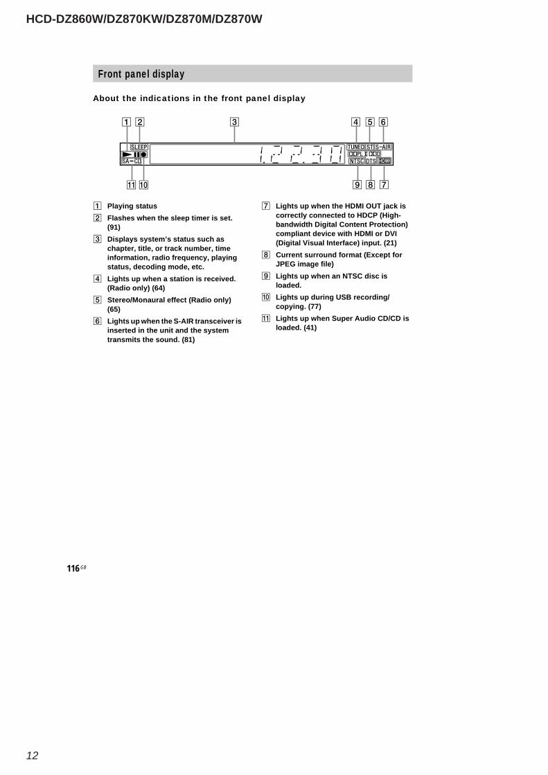
About the indications in the front panel display
Playing statusFlashes when the sleep timer is set.(91)Displays system’s status such aschapter, title, or track number, timeinformation, radio frequency, playingstatus, decoding mode, etc.Lights up when a station is received.(Radio only) (64)Stereo/Monaural effect (Radio only)(65)Lights up when the S-AIR transceiver isinserted in the unit and the systemtransmits the sound. (81)
Lights up when the HDMI OUT jack iscorrectly connected to HDCP (High-bandwidth Digital Content Protection)compliant device with HDMI or DVI(Digital Visual Interface) input. (21)Current surround format (Except forJPEG image file)Lights up when an NTSC disc isloaded.Lights up during USB recording/copying. (77)Lights up when Super Audio CD/CD isloaded. (41)
Front panel display
HCD-DZ860W/DZ870KW/DZ870M/DZ870W
13
118 GB
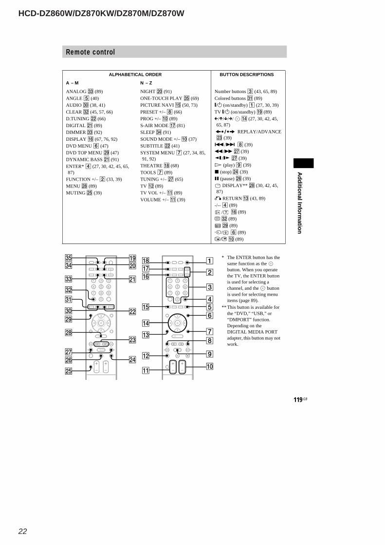
Remote control
SNOITPIRCSEDNOTTUBREDROLACITEBAHPLA
Z–NM–A
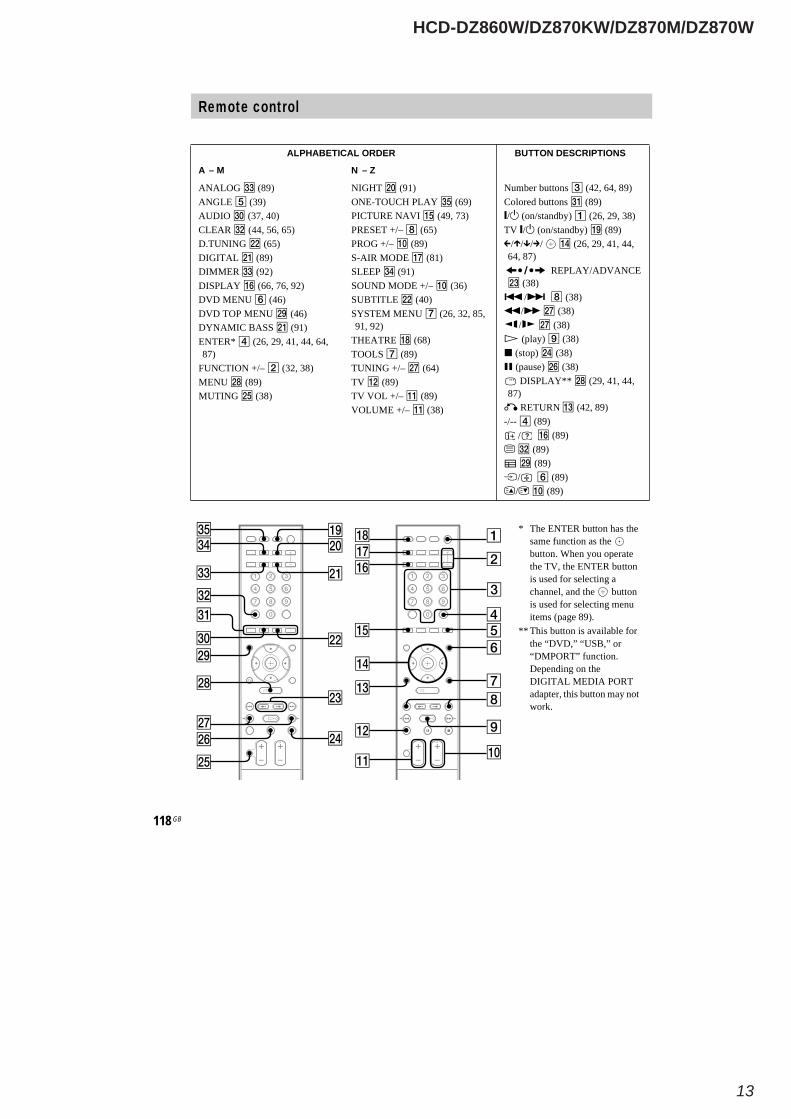
ANALOG (89)ANGLE (39)AUDIO (37, 40)CLEAR (44, 56, 65)D.TUNING (65)DIGITAL (89)DIMMER (92)DISPLAY (66, 76, 92)DVD MENU (46)DVD TOP MENU (46)DYNAMIC BASS (91)ENTER* (26, 29, 41, 44, 64,87)
FUNCTION +/– (32, 38)MENU (89)MUTING (38)
NIGHT (91)ONE-TOUCH PLAY (69)PICTURE NAVI (49, 73)PRESET +/– (65)PROG +/– (89)S-AIR MODE (81)SLEEP (91)SOUND MODE +/– (36)SUBTITLE (40)SYSTEM MENU (26, 32, 85,91, 92)
THEATRE (68)TOOLS (89)TUNING +/– (64)TV (89)TV VOL +/– (89)VOLUME +/– (38)
Number buttons (42, 64, 89)Colored buttons (89)/ (on/standby) (26, 29, 38)
TV / (on/standby) (89)/ / / / (26, 29, 41, 44,
64, 87)REPLAY/ADVANCE
(38)/ (38)
/ (38)/ (38)(play) (38)
(stop) (38)(pause) (38)DISPLAY** (29, 41, 44,
87)RETURN (42, 89)
-/-- (89)/ (89)
(89)(89)
/ (89)/ (89)
* The ENTER button has thesame function as thebutton. When you operatethe TV, the ENTER buttonis used for selecting achannel, and the buttonis used for selecting menuitems (page 89).
** This button is available forthe “DVD,” “USB,” or“DMPORT” function.Depending on theDIGITAL MEDIA PORTadapter, this button may notwork.
HCD-DZ860W/DZ870KW/DZ870M/DZ870W
14
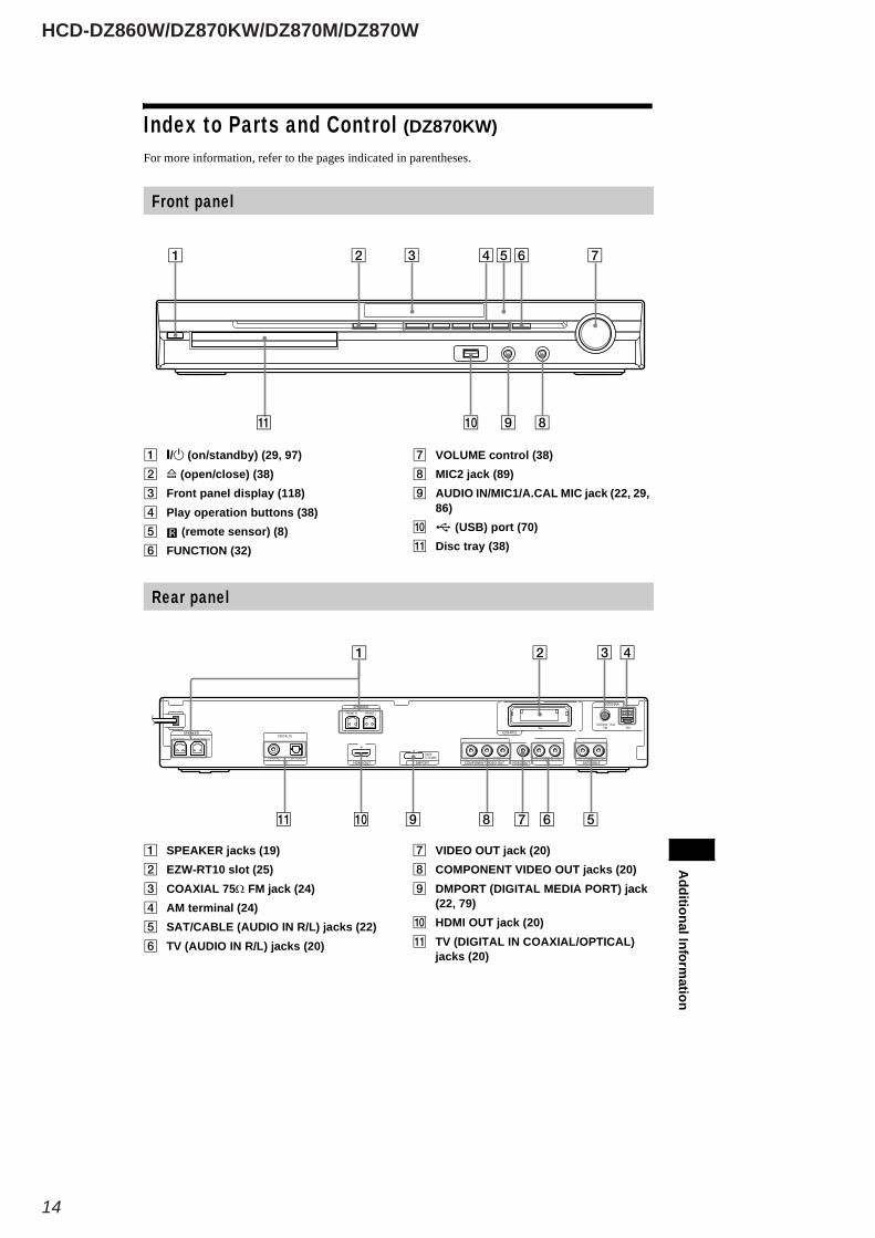
Index to Parts and Control (DZ870KW)For more information, refer to the pages indicated in parentheses.
/ (on/standby) (29, 97)(open/close) (38)
Front panel display (118)Play operation buttons (38)
(remote sensor) (8)FUNCTION (32)
VOLUME control (38)MIC2 jack (89)AUDIO IN/MIC1/A.CAL MIC jack (22, 29,86)
(USB) port (70)Disc tray (38)
Front panelA
dditionalInformation
SPEAKER jacks (19)EZW-RT10 slot (25)COAXIAL 75Ω FM jack (24)AM terminal (24)SAT/CABLE (AUDIO IN R/L) jacks (22)TV (AUDIO IN R/L) jacks (20)
VIDEO OUT jack (20)COMPONENT VIDEO OUT jacks (20)DMPORT (DIGITAL MEDIA PORT) jack(22, 79)HDMI OUT jack (20)TV (DIGITAL IN COAXIAL/OPTICAL)jacks (20)
Rear panel
CENTER SUBWOOFERDIGITAL IN
AUDIO IN
COAXIAL 75AMFM
PB/CB PR/CRY LRCOAXIAL OPTICAL
FRONT R FRONT L
SPEAKER
TUOIMDHVT VIDEO OUT TV
ANTENNA
DMPORT
SPEAKER
COMPONENT VIDEO OUTAUDIO IN LR
SAT/CABLE
DC5V0.7A MAX
EZW-RT10
HCD-DZ860W/DZ870KW/DZ870M/DZ870W
15
118 GB
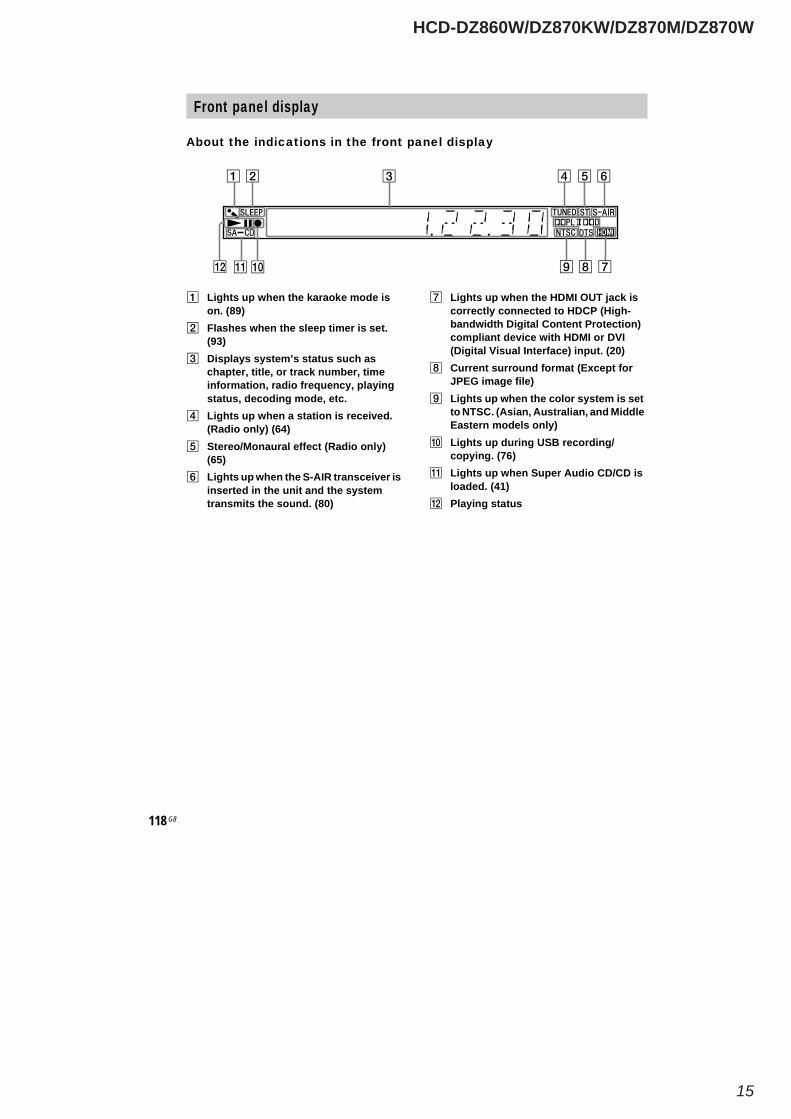
About the indications in the front panel display
Lights up when the karaoke mode ison. (89)Flashes when the sleep timer is set.(93)Displays system’s status such aschapter, title, or track number, timeinformation, radio frequency, playingstatus, decoding mode, etc.Lights up when a station is received.(Radio only) (64)Stereo/Monaural effect (Radio only)(65)Lights up when the S-AIR transceiver isinserted in the unit and the systemtransmits the sound. (80)
Lights up when the HDMI OUT jack iscorrectly connected to HDCP (High-bandwidth Digital Content Protection)compliant device with HDMI or DVI(Digital Visual Interface) input. (20)Current surround format (Except forJPEG image file)Lights up when the color system is setto NTSC. (Asian, Australian, and MiddleEastern models only)Lights up during USB recording/copying. (76)Lights up when Super Audio CD/CD isloaded. (41)Playing status
Front panel display
HCD-DZ860W/DZ870KW/DZ870M/DZ870W
16
120 GB
Remote control
SNOITPIRCSEDNOTTUBREDROLACITEBAHPLA
Z–NM–A
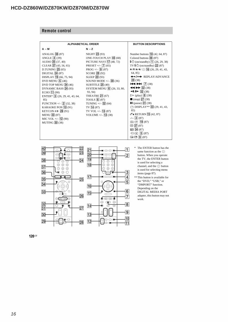
ANALOG (87)ANGLE (39)AUDIO (37, 40)CLEAR (43, 56, 65)D.TUNING (65)DIGITAL (87)DISPLAY (66, 75, 94)DVD MENU (46)DVD TOP MENU (46)DYNAMIC BASS (93)ECHO (90)ENTER* (26, 29, 41, 43, 64,85)
FUNCTION +/– (32, 38)KARAOKE PON (91)KEYCON #/ (91)MENU (87)MIC VOL +/– (90)MUTING (38)
NIGHT (93)ONE-TOUCH PLAY (68)PICTURE NAVI (48, 72)PRESET +/– (65)PROG +/– (87)SCORE (92)SLEEP (93)SOUND MODE +/– (36)SUBTITLE (40)SYSTEM MENU (26, 33, 80,93, 94)
THEATRE (67)TOOLS (87)TUNING +/– (64)TV (87)TV VOL +/– (87)VOLUME +/– (38)
Number buttons (42, 64, 87)Colored buttons (87)/ (on/standby) (26, 29, 38)
TV / (on/standby) (87)/ / / / (26, 29, 41, 43,
64, 85)REPLAY/ADVANCE
(38)/ (38)
/ (38)/ (38)(play) (38)
(stop) (38)(pause) (38)DISPLAY** (29, 41, 43,
85)RETURN (42, 87)
-/-- (87)/ (87)
(87)(87)
/ (87)/ (87)
* The ENTER button has thesame function as thebutton. When you operatethe TV, the ENTER buttonis used for selecting achannel, and the buttonis used for selecting menuitems (page 87).
** This button is available forthe “DVD,” “USB,” or“DMPORT” function.Depending on theDIGITAL MEDIA PORTadapter, this button may notwork.
HCD-DZ860W/DZ870KW/DZ870M/DZ870W
17
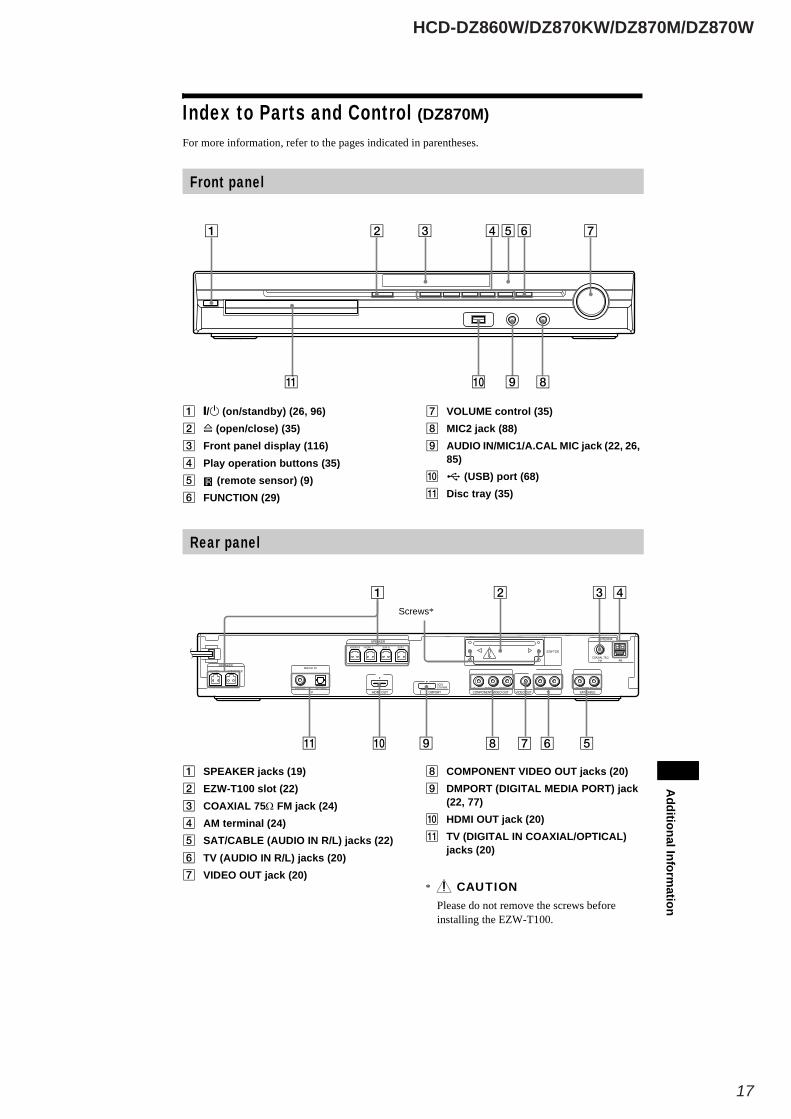
Index to Parts and Control (DZ870M)For more information, refer to the pages indicated in parentheses.
/ (on/standby) (26, 96)(open/close) (35)
Front panel display (116)Play operation buttons (35)
(remote sensor) (9)FUNCTION (29)
VOLUME control (35)MIC2 jack (88)AUDIO IN/MIC1/A.CAL MIC jack (22, 26,85)
(USB) port (68)Disc tray (35)
Front panel
AdditionalInform
ation
SPEAKER jacks (19)EZW-T100 slot (22)COAXIAL 75Ω FM jack (24)AM terminal (24)SAT/CABLE (AUDIO IN R/L) jacks (22)TV (AUDIO IN R/L) jacks (20)VIDEO OUT jack (20)
COMPONENT VIDEO OUT jacks (20)DMPORT (DIGITAL MEDIA PORT) jack(22, 77)HDMI OUT jack (20)TV (DIGITAL IN COAXIAL/OPTICAL)jacks (20)
* CAUTIONPlease do not remove the screws beforeinstalling the EZW-T100.
Rear panel
CENTER SUBWOOFER
AUDIO IN
COAXIAL 75AMFM
PB/CB PR/CRY LR
FRONT R FRONT L SUR R SUR L
SPEAKER
HDMI OUT VIDEO OUT TV
ANTENNA
DMPORT
SPEAKER
COMPONENT VIDEO OUTAUDIO IN LR
SAT/CABLE
EZW-T100
DC5V0.7A MAX
DIGITAL IN
COAXIAL OPTICALTV
Screws*
HCD-DZ860W/DZ870KW/DZ870M/DZ870W
18
116 GB
About the indications in the front panel display
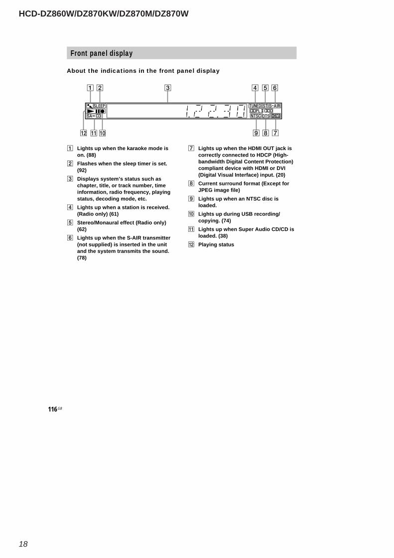
Lights up when the karaoke mode ison. (88)Flashes when the sleep timer is set.(92)Displays system’s status such aschapter, title, or track number, timeinformation, radio frequency, playingstatus, decoding mode, etc.Lights up when a station is received.(Radio only) (61)Stereo/Monaural effect (Radio only)(62)Lights up when the S-AIR transmitter(not supplied) is inserted in the unitand the system transmits the sound.(78)
Lights up when the HDMI OUT jack iscorrectly connected to HDCP (High-bandwidth Digital Content Protection)compliant device with HDMI or DVI(Digital Visual Interface) input. (20)Current surround format (Except forJPEG image file)Lights up when an NTSC disc isloaded.Lights up during USB recording/copying. (74)Lights up when Super Audio CD/CD isloaded. (38)Playing status
Front panel display
HCD-DZ860W/DZ870KW/DZ870M/DZ870W
19
AdditionalInform
ation
117 GB
Remote control
SNOITPIRCSEDNOTTUBREDROLACITEBAHPLA
Z–NM–A
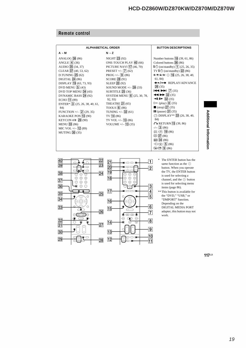
ANALOG (86)ANGLE (36)AUDIO (34, 37)CLEAR (40, 53, 62)D.TUNING (62)DIGITAL (86)DISPLAY (63, 73, 93)DVD MENU (43)DVD TOP MENU (43)DYNAMIC BASS (92)ECHO (89)ENTER* (25, 26, 38, 40, 61,84)
FUNCTION +/– (29, 35)KARAOKE PON (90)KEYCON #/ (90)MENU (86)MIC VOL +/– (89)MUTING (35)
NIGHT (92)ONE-TOUCH PLAY (66)PICTURE NAVI (46, 70)PRESET +/– (62)PROG +/– (86)SCORE (91)SLEEP (92)SOUND MODE +/– (33)SUBTITLE (36)SYSTEM MENU (25, 30, 78,92, 93)
THEATRE (65)TOOLS (86)TUNING +/– (61)TV (86)TV VOL +/– (86)VOLUME +/– (35)
Number buttons (39, 61, 86)Colored buttons (86)/ (on/standby) (25, 26, 35)
TV / (on/standby) (86)/ / / / (25, 26, 38, 40,
61, 84)REPLAY/ADVANCE
(35)/ (35)
/ (35)/ (35)(play) (35)
(stop) (35)(pause) (35)DISPLAY** (26, 38, 40,
84)RETURN (39, 86)
-/-- (86)/ (86)
(86)(86)
/ (86)/ (86)
* The ENTER button has thesame function as thebutton. When you operatethe TV, the ENTER buttonis used for selecting achannel, and the buttonis used for selecting menuitems (page 86).
** This button is available forthe “DVD,” “USB,” or“DMPORT” function.Depending on theDIGITAL MEDIA PORTadapter, this button may notwork.
HCD-DZ860W/DZ870KW/DZ870M/DZ870W
20
AdditionalInform
ation
Index to Parts and Control (DZ870W)For more information, refer to the pages indicated in parentheses.
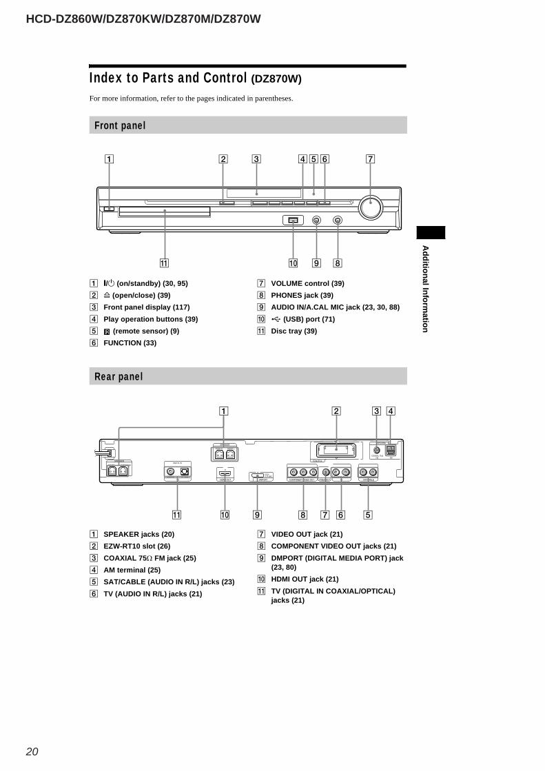
/ (on/standby) (30, 95)(open/close) (39)
Front panel display (117)Play operation buttons (39)
(remote sensor) (9)FUNCTION (33)
VOLUME control (39)PHONES jack (39)AUDIO IN/A.CAL MIC jack (23, 30, 88)
(USB) port (71)Disc tray (39)
Front panel
SPEAKER jacks (20)EZW-RT10 slot (26)COAXIAL 75Ω FM jack (25)AM terminal (25)SAT/CABLE (AUDIO IN R/L) jacks (23)TV (AUDIO IN R/L) jacks (21)
VIDEO OUT jack (21)COMPONENT VIDEO OUT jacks (21)DMPORT (DIGITAL MEDIA PORT) jack(23, 80)HDMI OUT jack (21)TV (DIGITAL IN COAXIAL/OPTICAL)jacks (21)
Rear panel
CENTER SUBWOOFERDIGITAL IN
AUDIO IN
COAXIAL 75AMFM
PB/CB PR/CRY LRCOAXIAL OPTICAL
FRONT R FRONT L
SPEAKER
TUOIMDHVT VIDEO OUT TV
ANTENNA
DMPORT
SPEAKER
COMPONENT VIDEO OUTAUDIO IN LR
SAT/CABLE
DC5V0.7A MAX
EZW-RT10
HCD-DZ860W/DZ870KW/DZ870M/DZ870W
21
AdditionalInform
ation
117 GB
About the indications in the front panel display
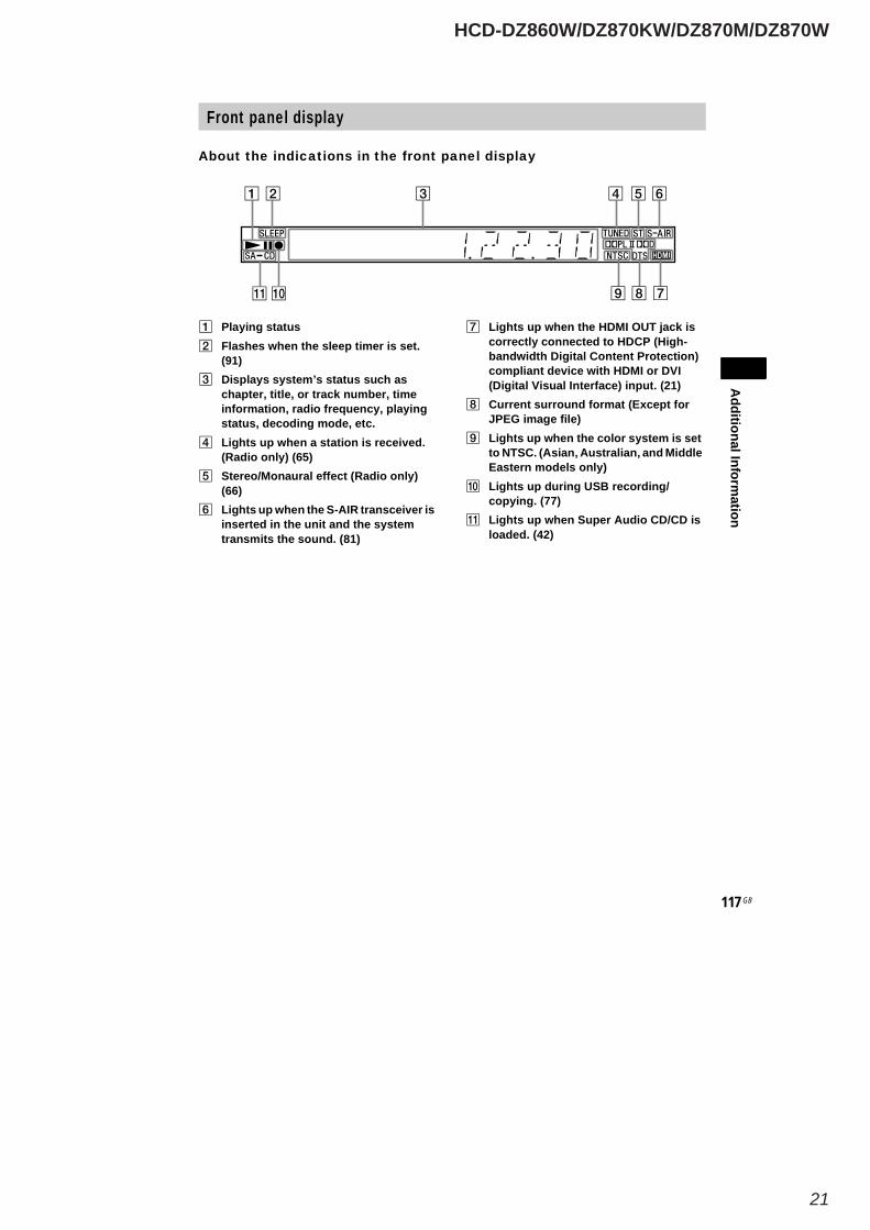
Playing statusFlashes when the sleep timer is set.(91)Displays system’s status such aschapter, title, or track number, timeinformation, radio frequency, playingstatus, decoding mode, etc.Lights up when a station is received.(Radio only) (65)Stereo/Monaural effect (Radio only)(66)Lights up when the S-AIR transceiver isinserted in the unit and the systemtransmits the sound. (81)
Lights up when the HDMI OUT jack iscorrectly connected to HDCP (High-bandwidth Digital Content Protection)compliant device with HDMI or DVI(Digital Visual Interface) input. (21)Current surround format (Except forJPEG image file)Lights up when the color system is setto NTSC. (Asian, Australian, and MiddleEastern models only)Lights up during USB recording/copying. (77)Lights up when Super Audio CD/CD isloaded. (42)
Front panel display
HCD-DZ860W/DZ870KW/DZ870M/DZ870W
22
AdditionalInform
ation
119 GB
Remote control
SNOITPIRCSEDNOTTUBREDROLACITEBAHPLA
Z–NM–A
ANALOG (89)ANGLE (40)AUDIO (38, 41)CLEAR (45, 57, 66)D.TUNING (66)DIGITAL (89)DIMMER (92)DISPLAY (67, 76, 92)DVD MENU (47)DVD TOP MENU (47)DYNAMIC BASS (91)ENTER* (27, 30, 42, 45, 65,87)
FUNCTION +/– (33, 39)MENU (89)MUTING (39)
NIGHT (91)ONE-TOUCH PLAY (69)PICTURE NAVI (50, 73)PRESET +/– (66)PROG +/– (89)S-AIR MODE (81)SLEEP (91)SOUND MODE +/– (37)SUBTITLE (41)SYSTEM MENU (27, 34, 85,91, 92)
THEATRE (68)TOOLS (89)TUNING +/– (65)TV (89)TV VOL +/– (89)VOLUME +/– (39)
Number buttons (43, 65, 89)Colored buttons (89)/ (on/standby) (27, 30, 39)
TV / (on/standby) (89)/ / / / (27, 30, 42, 45,
65, 87)REPLAY/ADVANCE
(39)/ (39)
/ (39)/ (39)(play) (39)
(stop) (39)(pause) (39)DISPLAY** (30, 42, 45,
87)RETURN (43, 89)
-/-- (89)/ (89)
(89)(89)
/ (89)/ (89)
* The ENTER button has thesame function as thebutton. When you operatethe TV, the ENTER buttonis used for selecting achannel, and the buttonis used for selecting menuitems (page 89).
** This button is available forthe “DVD,” “USB,” or“DMPORT” function.Depending on theDIGITAL MEDIA PORTadapter, this button may notwork.
HCD-DZ860W/DZ870KW/DZ870M/DZ870W
23
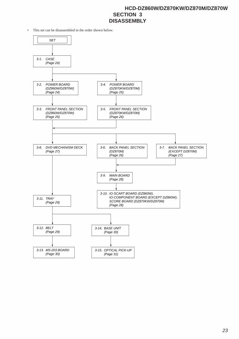
SECTION 3DISASSEMBLY
• This set can be disassembled in the order shown below.
3-6. BACK PANEL SECTION (DZ870M) (Page 26)
3-7. BACK PANEL SECTION (EXCEPT DZ870M) (Page 27)
3-9. MAIN BOARD (Page 28)
3-1. CASE (Page 24)
3-2. POWER BOARD (DZ860W/DZ870W) (Page 24)
SET
3-3. FRONT PANEL SECTION (DZ860W/DZ870W) (Page 25)
3-4. POWER BOARD (DZ870KW/DZ870M) (Page 25)
3-5. FRONT PANEL SECTION (DZ870KW/DZ870M) (Page 26)
3-8. DVD MECHANISM DECK (Page 27)
3-11. TRAY (Page 29)
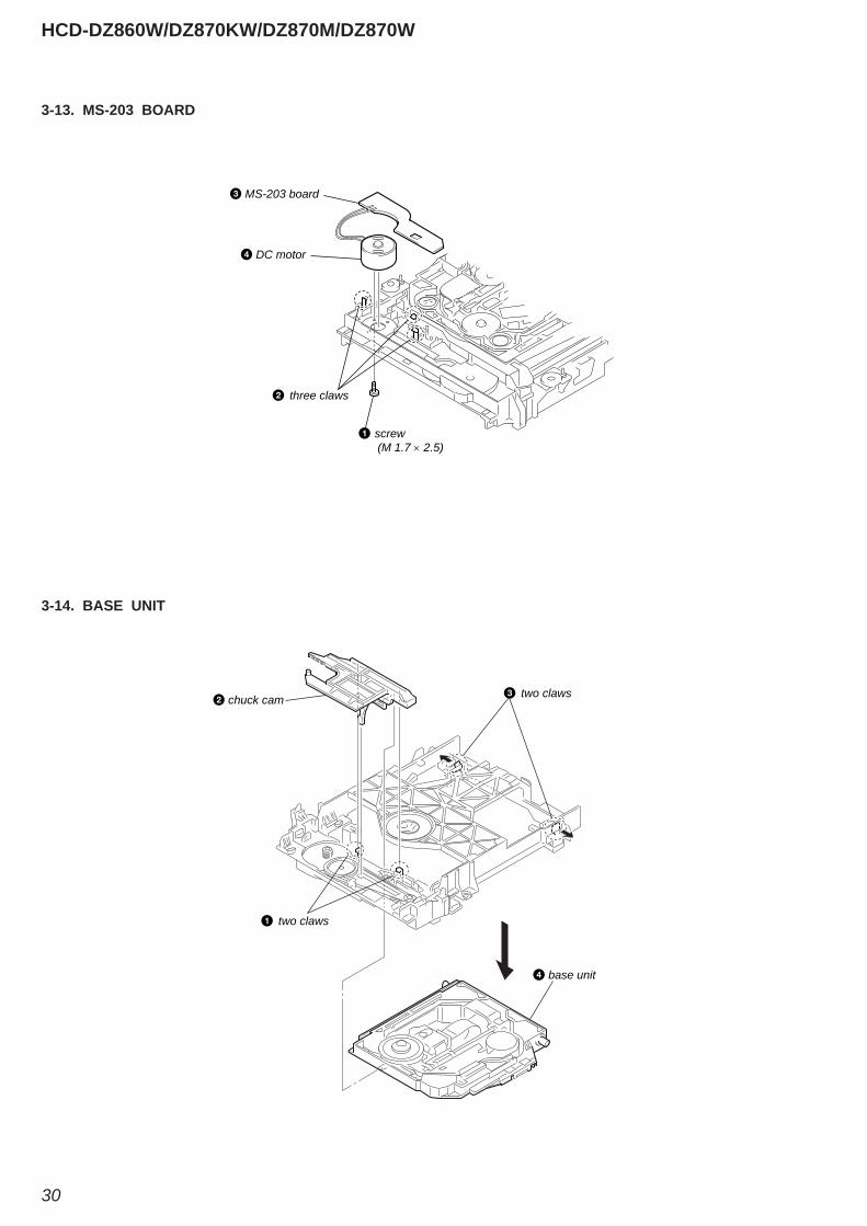
3-13. MS-203 BOARD (Page 30)
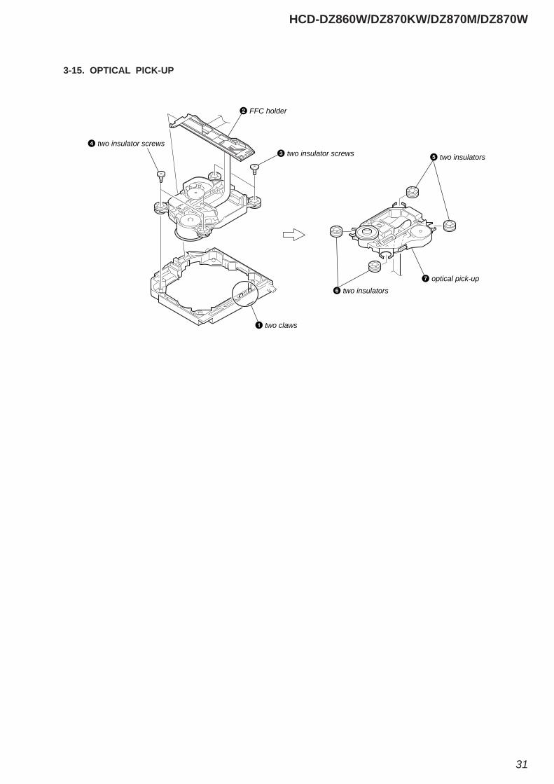
3-15. OPTICAL PICK-UP (Page 31)
3-10. IO-SCART BOARD (DZ860W), IO-COMPONENT BOARD (EXCEPT DZ860W), SCORE BOARD (DZ870KW/DZ870M) (Page 28)
3-12. BELT (Page 29)
3-14. BASE UNIT (Page 30)
HCD-DZ860W/DZ870KW/DZ870M/DZ870W
24
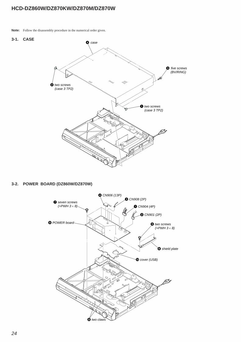
Note: Follow the disassembly procedure in the numerical order given.
3-1. CASE
3-2. POWER BOARD (DZ860W/DZ870W)
five screws (BV/RING)
case
two screws (case 3 TP2)
two screws (case 3 TP2)
CN904 (4P)
CN901 (2P)
shield plate
CN908 (2P) CN906 (13P)
two screws (+PWH 3 × 8)
seven screws (+PWH 3 × 8)
two claws
POWER board
cover (USB)
HCD-DZ860W/DZ870KW/DZ870M/DZ870W
25
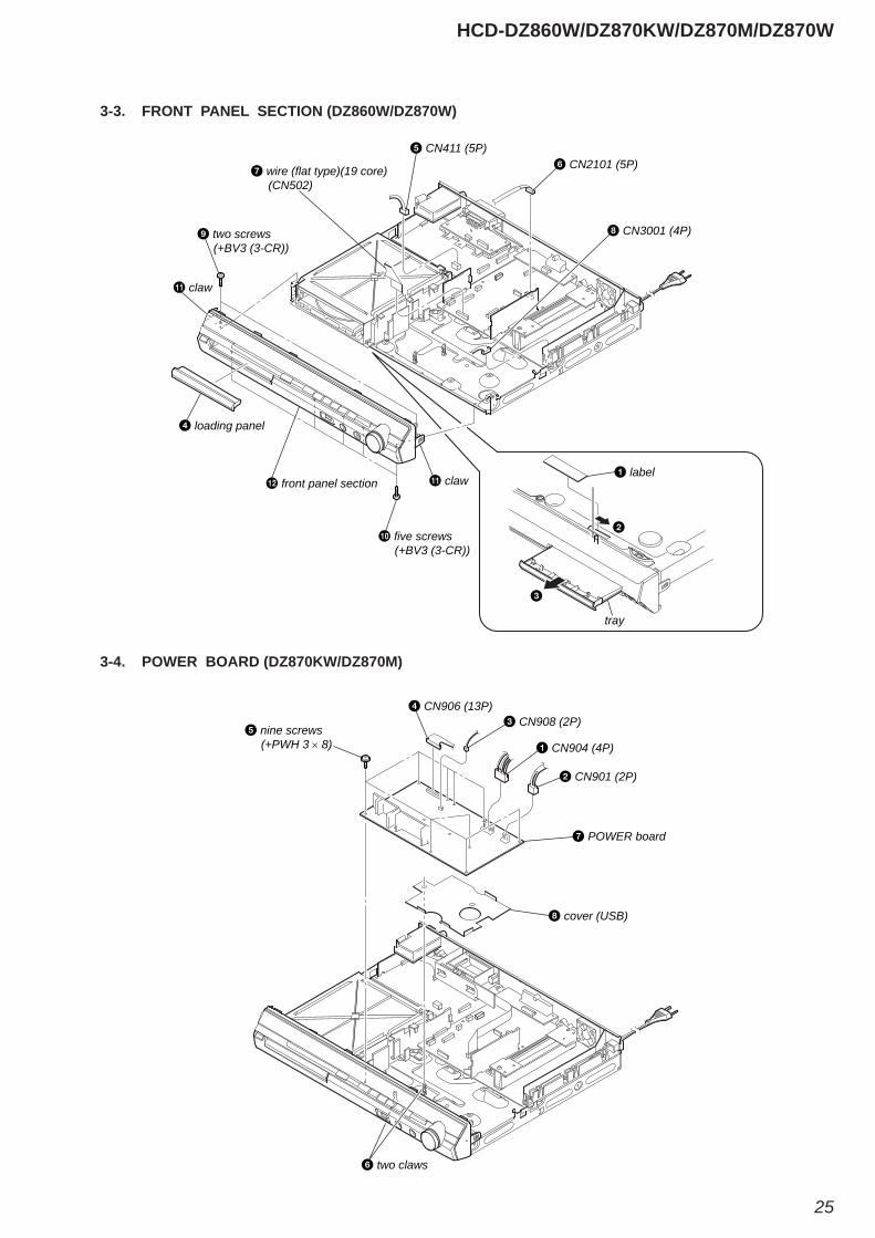
3-3. FRONT PANEL SECTION (DZ860W/DZ870W)
3-4. POWER BOARD (DZ870KW/DZ870M)
two screws (+BV3 (3-CR))
five screws (+BV3 (3-CR))
front panel section
claw
claw
loading panel
CN411 (5P)
CN3001 (4P)
CN2101 (5P) wire (flat type)(19 core) (CN502)
label
tray
CN904 (4P)
CN901 (2P)
CN908 (2P) CN906 (13P)
nine screws (+PWH 3 × 8)
two claws
POWER board
cover (USB)
HCD-DZ860W/DZ870KW/DZ870M/DZ870W
26
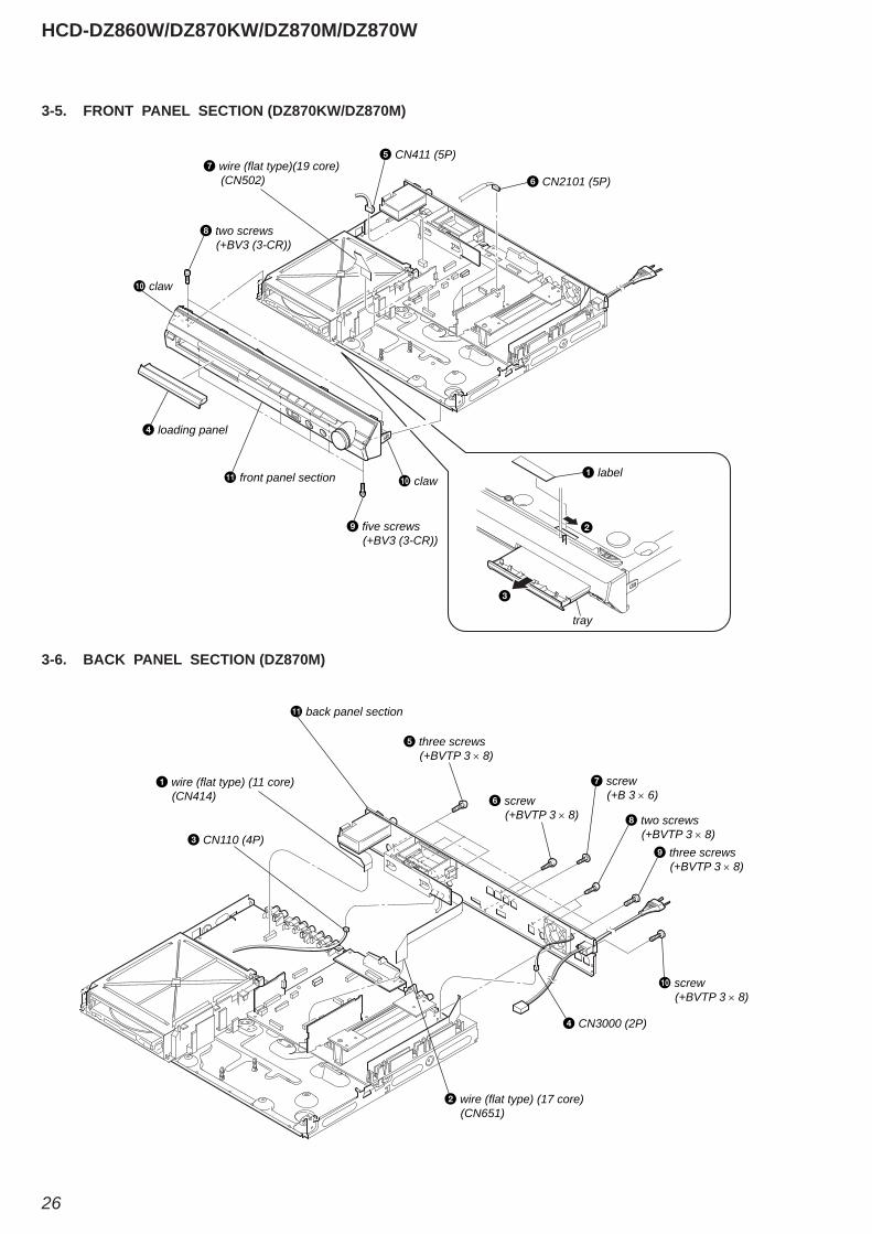
3-5. FRONT PANEL SECTION (DZ870KW/DZ870M)
3-6. BACK PANEL SECTION (DZ870M)
two screws (+BV3 (3-CR))
five screws (+BV3 (3-CR))
front panel section claw
claw
loading panel
CN411 (5P)
CN2101 (5P) wire (flat type)(19 core)
(CN502)
label
tray
CN3000 (2P)
CN110 (4P)
wire (flat type) (11 core) (CN414)
wire (flat type) (17 core) (CN651)
three screws (+BVTP 3 × 8)
back panel section
two screws (+BVTP 3 × 8)
three screws (+BVTP 3 × 8)
screw (+BVTP 3 × 8)
screw (+BVTP 3 × 8)
screw (+B 3 × 6)
HCD-DZ860W/DZ870KW/DZ870M/DZ870W
27
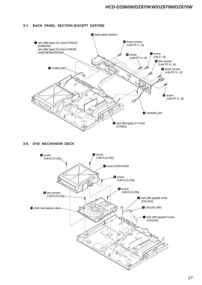
3-8. DVD MECHANISM DECK
3-7. BACK PANEL SECTION (EXCEPT DZ870M)
CN3000 (2P)
CN804 (4P)
wire (flat type) (11 core) (CN414) (DZ860W) wire (flat type) (9 core) (CN419) (DZ870KW/DZ870W)
wire (flat type) (17 core) (CN651)
three screws (+BVTP 3 × 8)
back panel section
two screws (+BVTP 3 × 8)
three screws (+BVTP 3 × 8)
screw (+BVTP 3 × 8)
screw (+BVTP 3 × 8)
screw (+B 3 × 6)
CN1201 (6P)
wire (flat type)(24 core) (CN1101)
wire (flat type)(5 core) (CN1202)
screw (+BV3 (3-CR))
two screws (+BV3 (3-CR))
DVD mechanism deck
screw (+BV3 (3-CR))
screw (+BV3 (3-CR))
screw (+BV3 (3-CR))
cover (CDM-DSR)
HCD-DZ860W/DZ870KW/DZ870M/DZ870W
28
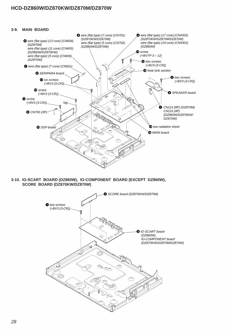
3-10. IO-SCART BOARD (DZ860W), IO-COMPONENT BOARD (EXCEPT DZ860W), SCORE BOARD (DZ870KW/DZ870W)
3-9. MAIN BOARD
CN114 (8P) (DZ870M) CN115 (4P) (DZ860W/DZ870KW/ DZ870W)
two screws (+BV3 (3-CR))
screw (+BV3 (3-CR))
lug screw
(+BV3 (3-CR))
DSP board
two screws (+BV3 (3-CR))
six screws (+BV3 (3-CR))
MAIN board
heat sink section
two radiation sheet
SPEAKER board
wire (flat type) (13 core) (CN604) (DZ870M) wire (flat type) (11 core) (CN605) (DZ860W/DZ870KW) wire (flat type) (9 core) (CN606) (DZ870W)
wire (flat type) (7 core) (CN601)
SERIPARA board
CN700 (3P)
wire (flat type) (17 core) (CN4302) (DZ870KW/DZ870M/DZ870W) wire (flat type) (19 core) (CN4301) (DZ860W)
wire (flat type) (7 core) (CN701) (DZ870KW/DZ870M) wire (flat type) (5 core) (CN702) (DZ860W/DZ870W)
screw (+BVTP 3 × 12)
two screws (+BV3 (3-CR))
IO-SCART board (DZ860W) IO-COMPONENT board (DZ870KW/DZ870M/DZ870W)
SCORE board (DZ870KW/DZ870M)
HCD-DZ860W/DZ870KW/DZ870M/DZ870W
29
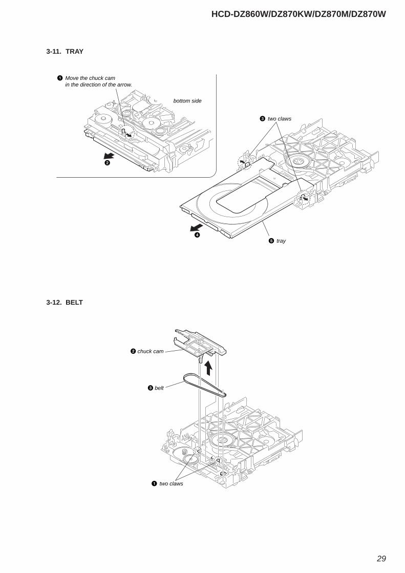
3-12. BELT
3-11. TRAY
two claws
tray
Move the chuck cam in the direction of the arrow.
bottom side
two claws
belt
chuck cam
HCD-DZ860W/DZ870KW/DZ870M/DZ870W
30
3-14. BASE UNIT
3-13. MS-203 BOARD
three claws
MS-203 board
DC motor
screw (M 1.7 × 2.5)
two claws
two claws chuck cam
base unit
HCD-DZ860W/DZ870KW/DZ870M/DZ870W
31
3-15. OPTICAL PICK-UP
FFC holder
two insulator screws two insulator screws
two insulators
two insulators optical pick-up
two claws
HCD-DZ860W/DZ870KW/DZ870M/DZ870W
32
SECTION 4TEST MODE
Note: Incorrect operations may be performed if the test mode is not entered properly.
In this case, press the [?/1] button to turn the power off, and retry to enter the test mode.
1. Cold Reset• The cold reset clears all data including preset data stored in the
RAM to initial conditions. Execute this mode when returning the set to the customers.
Procedure:1. Press the [?/1] button to turn the power on. 2. Press three buttons [x], [A] and [?/1] simultaneously.3. When this button is operated, display as “COLD RESET” for
a while and all of the settings are reset.
2. Panel Test Mode• This mode is used to check the software version, FL and
KEY.
2-1. Display Test ModeProcedure:1. Press the [?/1] button to turn the power on.2. Press three buttons [X], [.] and [A] simultaneously.3. When the display test mode is activated, all segments are turned
on.4. To exit from this mode, press three buttons [X], [.] and [A]
simultaneously.
2-2. Version Test ModeProcedure:1. When the display test mode is activated, press the [.]
button and the message “DSR9EW” (DZ860W), “DSR9KW” (DZ870KW), “DSR9KD” (DZ870M), “DSR9W” (DZ870W) are displayed, the version test mode is activated.
2. Whenever the [.] button is pressed, the display changes in the following order.
“DSR9KW” (Model name) “ASIA2*1” (Destination) MC Version SYS Version UI Version DVD Version ST Version TA Version DSP Version TM Version MM Version CLA Version CEC Version SAIR Version
*1: ASIA2 changes depending on destination.3. Press the [>] button and the date of the software production
is displayed.4. Press the [>] button again and the version is displayed.5. To exit from this mode, press three buttons [X], [.] and [A]
simultaneously.
2-3. Key Test ModeProcedure:1. When the display test mode is activated, press the [H] button,
to select the key test mode.2. To enter the KEY test mode, the fl uorescent indicator displays
“K0 V0”. Each time an another button is pressed, “KEY” value increases. However, once a button is pressed, it is no longer taken into account. When all keys are pressed correctly, “K8 V0” is displayed.
3. When the [VOLUME] control is turned in the direction of (+), “V0” is changed to “V1”, then ... “V9”.
When the [VOLUME] control is turned in the direction of (–), “V0” is changed to “V9”, then ... “V1”.
4. To exit from this mode, press three buttons [X], [.] and [A] simultaneously.
3. Disc Tray LockThe disc tray lock function for the antitheft of an demonstration disc in the store is equipped.Setting Procedure :1. Press the [?/1] button to turn the set on.2. Press the [FUNCTION] button to set DVD function.3. Insert a disc.4. Press the [x] button and the [A] button simultaneously for fi ve
seconds.5. The message “LOCKED” is displayed and the tray is locked.Releasing Procedure :1. Press the [x] button and the [A] button simultaneously for fi ve
seconds again.2. The message “UNLOCKED” is displayed and the tray is
unlocked.Note: When “LOCKED” is displayed, the tray lock is not released by
turning power on/off with the [?/1] button.
4. DVD Ship ModeUse this mode when returning the set to the customer after repair.Procedure:1. Press the [?/1] button to turn the set on.2. Press the [FUNCTION] button to set the function “DVD”.3. Remove all Discs, and then press two buttons [H] and [?/1]
simultaneously.4. After a message “MECHA LOCK” h “PULL PLUG” is
displayed on the fl uorescent indicator tube, pull out the AC plug.
5. To exit from this mode, press the [?/1] button to turn the set on.
5. AM Step Change (Except AEP, UK, E models)• A step of AM channels can be changed over between 9 kHz
and 10 kHz.Procedure:1. Press the [?/1] button to turn the set ON. 2. Select the function “TUNER”, and press [FUNCTION] button
to select the BAND “AM”.3. Press the [?/1] button to turn the set OFF. 4. Press two buttons [>] and [?/1] simultaneously, and the
display of fl uorescent indicator tube changes to “AM 9k STEP” or “AM 10k STEP”, and thus the channel step is changed over.
6. Product OutThis mode moves the optical pick-up to the position durable to vibration and clears all data including preset data stored in the RAM to initial conditions. Use this mode when returning the set to the customer after repair.Procedure:1. Press the [?/1] button to turn the power on.2. Press the [FUNCTION] button to set the function “DVD”.3. Remove all discs, and then press three buttons [>], [A] and
[?/1] simultaneously.4. After the “STANDBY” blinking display fi nishes, the message
“MECHA LOCK” h “PULL PLUG” is displayed on the fl uorescent indicator tube disconnect the AC power plug, then the ship mode is set.

HCD-DZ860W/DZ870KW/DZ870M/DZ870W
33
7-1. GENERAL DESCRIPTIONThe IOP measurement allows you to make diagnosis and adjustment simply by using the remote commander and monitor TV. The instructions, diagnosis results, etc. are given on the on-screen display (OSD).Be sure to execute the IOP measurement when a BU (Base Unit) is replaced.
7-2. HOW TO ENTER TEST MODEWhile pressing the [x] and [A] buttons simultaneously, turn [VOLUME] control in the direction of (+) with the DVD player in power on.The Test Mode starts, displayed “SERVICE IN” on this model display then the menu shown below will be displayed on the TV screen.* The display of the “Model Name” of the “Remocon Diagnosis
Menu” change with the model and the destination. Refer to below on the model name.
DZ860W : DSR9EW DZ870KW : DSR9KW DZ870M : DSR9KD DZ870W : DSR9W
The menu above is the Remocon Diagnosis Menu screen which consists of fi ve main functions. At the bottom of the menu screen, the model name and IF-con version. To exit from the Test Mode, press the power button on the remote commander.
7-3. EXECUTING IOP MEASUREMENTIn order to execute IOP measurement, the following standard procedures must be followed.
(1) In power on, while pressing the [x] and [A] buttons simultaneously, turn the [VOLUME] control in the direction of (+).
(2) Select “2. Drive Manual Operation” by pressing the [2] button on the remote commander. The screen will appear as shown.
(3) Select “3. Manual Adjustment” by pressing the [3] button on the remote commander. The screen will appear as shown.
(4) Select “6. IOP” by pressing the [6] button on the remote commander.
(5) Wait until a hexadecimal number appear.
(6) Convert each data from hexadecimal to decimal using conversion table.
(7) Please fi nd the label on the rear of the BU (Base Unit). The default IOP value is written in the label.
(8) Subtract between these two values.
(9) If the remainder is smaller than 93 (decimal), then it is OK. However if the value is higher than 93, then the BU is defective and need to be change.
(10) Press the [RETURN] button on the remote commander to return back to previous menu.
(11) Press the [0] button on the remote commander to return to Top Menu.
DVD SECTION
Remocon Diagnosis Menu
0. External Chip Check1. Servo Parameter Check2. Drive Manual Operation3. Emergency History4. Version Information
Model NameIF-con : Ver. XX.XX (XXXX)Syscon : Ver. X.XXX
: DSR9KW_XX*1
*1: Changes depending on destination
Remocon Diagnosis Menu
0. External Chip Check1. Servo Parameter Check2. Drive Manual Operation3. Emergency History4. Version Information
Model NameIF-con : Ver. XX.XX (XXXX)Syscon : Ver. X.XXX
: DSR9KW_XX*1
*1: Changes depending on destination
Drive Manual Operation
1. Servo Control2. Track/Layer Jump3. Manual Adjustment4. Tray Aging Mode5. MIRR time adjust0. Return to Top Menu
Manual Adjust
1. Track Balance Adjust:2. Track Gain Adjust:3. Focus Balance Adjust:4. Focus Gain Adjust:5. Eq Boost Adjust:6. Iop:7. TRV. Level:8. S curve(FE) Level:9. RFL(PI) Level:0. MIRR Time:
Change Value[RETURN] Return to previous menu
Manual Adjust
1. Track Balance Adjust:2. Track Gain Adjust:3. Focus Balance Adjust:4. Focus Gain Adjust:5. Eq Boost Adjust:6. Iop. 4E:7. TRV. Level:8. S curve(FE) Level:9. RFL(PI) Level:0. MIRR Time:
[RETURN] Return to previous menu Change Value
HCD-DZ860W/DZ870KW/DZ870M/DZ870W
34
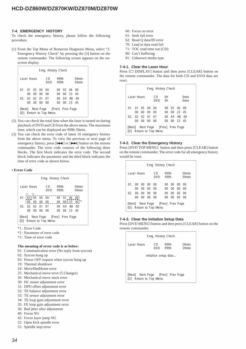
7-4. EMERGENCY HISTORYTo check the emergency history, please follow the following procedure.
(1) From the Top Menu of Remocon Diagnosis Menu, select “3. Emergency History Check” by pressing the [3] button on the remote commander. The following screen appears on the on-screen display.
(2) You can check the total time when the laser is turned on during playback of DVD and CD from the above menu. The maximum time, which can be displayed are 999h 59min.
(3) You can check the error code of latest 10 emergency history from the above menu. To view the previous or next page of emergency history, press [.] or [>] button on the remote commander. The error code consists of the following three blocks. The fi rst block indicates the error code. The second block indicates the parameter and the third block indicates the time of error code as shown below.
• Error Code
*1 : Error Code *2 : Parameter of error code *3 : Time of error code
The meaning of error code is as below: 01: Communication error (No reply from syscon) 02: Syscon hung up 03: Power OFF request when syscon hung up 19: Thermal shutdown 24: MoveSledHome error 25: Mechanical move error (5 Changer) 26: Mechanical move stack error 30: DC motor adjustment error 31: DPD offset adjustment error 32: TE balance adjustment error 33: TE sensor adjustment error 34: TE loop gain adjustment error 35: FE loop gain adjustment error 36: Bad jitter after adjustment 40: Focus NG 42: Focus layer jump NG 52: Open kick spindle error 51: Spindle stop error
60: Focus on error 61: Seek fail error 62: Read Q data/ID error 70: Lead in data read fail 71: TOC read time out (CD) 80: Can’t buffering 81: Unknown media type
7-4-1. Clear the Laser HourPress [ DISPLAY] button and then press [CLEAR] button on the remote commander. The data for both CD and DVD data are reset.
7-4-2. Clear the Emergency HistoryPress [DVD TOP MENU] button and then press [CLEAR] button on the remote commander. The error code for all emergency history would be reset.
7-4-3. Clear the Initialize Setup DataPress [DVD MENU] button and then press [CLEAR] button on the remote commander.
Emg. History Check
01. 01 05 04 04
Laser Hours CD 999h 59minDVD 999h 59min
00 92 46 0000 00 00 00 00 00 23 45
02. 02 02 01 01 00 A9 4B 0000 00 00 00 00 00 23 45
[Next] Next Page [Prev] Prev Page[O] Return to Top Menu
Emg. History Check
01. 01 05 04 04
Laser Hours CD 999h 59minDVD 999h 59min
00 92 46 0000 00 00 00 00 00 23 45
02. 02 02 01 01 00 A9 4B 0000 00 00 00 00 00 23 45
[Next] Next Page [Prev] Prev Page[O] Return to Top Menu
*1 *2
*3
Emg. History Check
01. 01 05 04 04
Laser Hours CD 0h 0minDVD 0h 0min
00 92 46 0000 00 00 00 00 00 23 45
02. 02 02 01 01 00 A9 4B 0000 00 00 00 00 00 23 45
[Next] Next Page [Prev] Prev Page[O] Return to Top Menu
01. 00 00 00 00
Laser Hours CD 999h 59minDVD 999h 59min
00 00 00 0000 00 00 00 00 00 00 00
02. 00 00 00 00 00 00 00 0000 00 00 00 00 00 00 00
[Next] Next Page [Prev] Prev Page[O] Return to Top Menu
Emg. History Check
Emg. History Check
initialize setup data...
Laser Hours CD 999h 59minDVD 999h 59min
[Next] Next Page [Prev] Prev Page[O] Return to Top Menu
HCD-DZ860W/DZ870KW/DZ870M/DZ870W
35
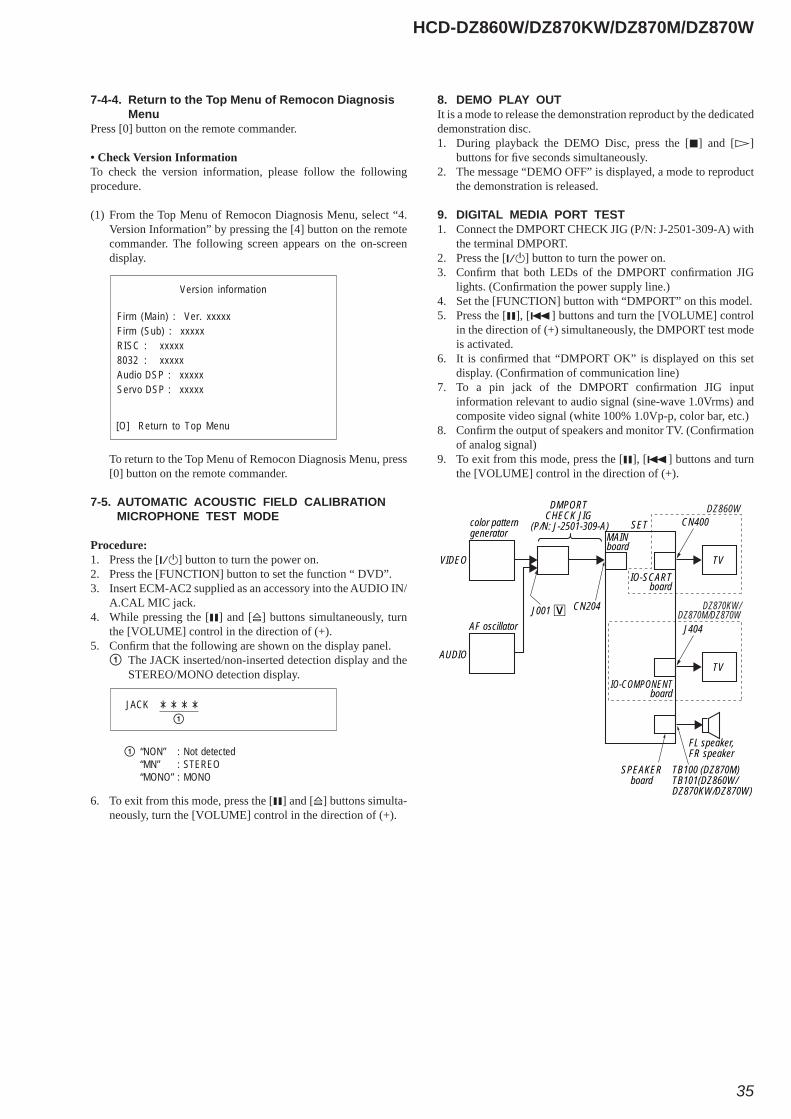
8. DEMO PLAY OUTIt is a mode to release the demonstration reproduct by the dedicated demonstration disc.1. During playback the DEMO Disc, press the [x] and [H]
buttons for fi ve seconds simultaneously.2. The message “DEMO OFF” is displayed, a mode to reproduct
the demonstration is released.
9. DIGITAL MEDIA PORT TEST1. Connect the DMPORT CHECK JIG (P/N: J-2501-309-A) with
the terminal DMPORT.2. Press the [?/1] button to turn the power on.3. Confi rm that both LEDs of the DMPORT confi rmation JIG
lights. (Confi rmation the power supply line.)4. Set the [FUNCTION] button with “DMPORT” on this model.5. Press the [X], [.] buttons and turn the [VOLUME] control
in the direction of (+) simultaneously, the DMPORT test mode is activated.
6. It is confi rmed that “DMPORT OK” is displayed on this set display. (Confi rmation of communication line)
7. To a pin jack of the DMPORT confi rmation JIG input information relevant to audio signal (sine-wave 1.0Vrms) and composite video signal (white 100% 1.0Vp-p, color bar, etc.)
8. Confi rm the output of speakers and monitor TV. (Confi rmation of analog signal)
9. To exit from this mode, press the [X], [.] buttons and turn the [VOLUME] control in the direction of (+).
7-4-4. Return to the Top Menu of Remocon Diagnosis Menu
Press [0] button on the remote commander.
• Check Version InformationTo check the version information, please follow the following procedure.
(1) From the Top Menu of Remocon Diagnosis Menu, select “4. Version Information” by pressing the [4] button on the remote commander. The following screen appears on the on-screen display.
To return to the Top Menu of Remocon Diagnosis Menu, press [0] button on the remote commander.
7-5. AUTOMATIC ACOUSTIC FIELD CALIBRATION MICROPHONE TEST MODE
Procedure:1. Press the [?/1] button to turn the power on.2. Press the [FUNCTION] button to set the function “ DVD”.3. Insert ECM-AC2 supplied as an accessory into the AUDIO IN/
A.CAL MIC jack.4. While pressing the [X] and [A] buttons simultaneously, turn
the [VOLUME] control in the direction of (+).5. Confi rm that the following are shown on the display panel.1 The JACK inserted/non-inserted detection display and the
STEREO/MONO detection display.
6. To exit from this mode, press the [X] and [A] buttons simulta-neously, turn the [VOLUME] control in the direction of (+).
Version information
[O] Return to Top Menu
Firm (Main) : Ver. xxxxxFirm (Sub) : xxxxxRISC : xxxxx8032 : xxxxxAudio DSP : xxxxxServo DSP : xxxxx
“NON” : Not detected “MN” : STEREO “MONO” : MONO
JACK
color patterngenerator
DMPORT CHECK JIG
(P/N: J-2501-309-A)MAINboard
TV
SET
CN204
CN400
J001AF oscillator
FL speaker, FR speaker
IO-SCARTboard
SPEAKERboard
TB100 (DZ870M)TB101(DZ860W/DZ870KW/DZ870W)
VIDEO
AUDIOTV
J404
IO-COMPONENTboard
DZ860W
DZ870KW/DZ870M/DZ870W
HCD-DZ860W/DZ870KW/DZ870M/DZ870W
36
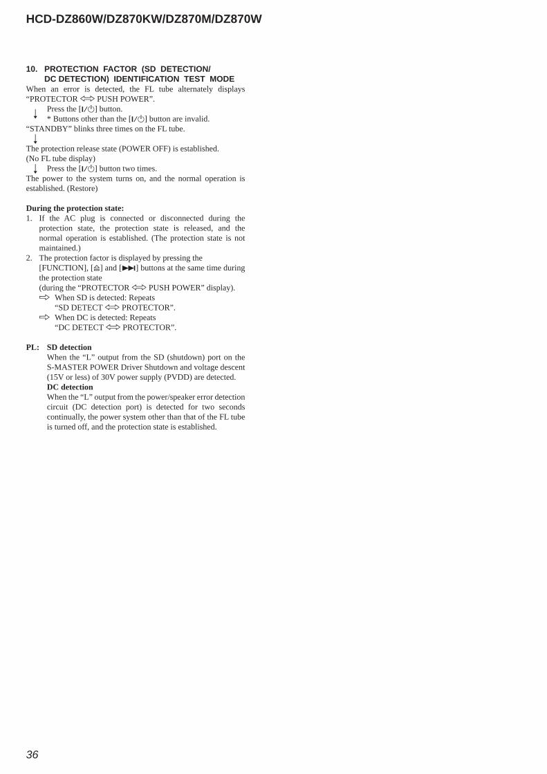
10. PROTECTION FACTOR (SD DETECTION/ DC DETECTION) IDENTIFICATION TEST MODE
When an error is detected, the FL tube alternately displays “PROTECTOR h PUSH POWER”.
r Press the [?/1] button.
* Buttons other than the [?/1] button are invalid.“STANDBY” blinks three times on the FL tube. r
The protection release state (POWER OFF) is established.(No FL tube display) r Press the [?/1] button two times.The power to the system turns on, and the normal operation is established. (Restore)
During the protection state: 1. If the AC plug is connected or disconnected during the
protection state, the protection state is released, and the normal operation is established. (The protection state is not maintained.)
2. The protection factor is displayed by pressing the [FUNCTION], [A] and [>] buttons at the same time during
the protection state (during the “PROTECTOR h PUSH POWER” display). k When SD is detected: Repeats “SD DETECT h PROTECTOR”. k When DC is detected: Repeats “DC DETECT h PROTECTOR”.
PL: SD detection When the “L” output from the SD (shutdown) port on the
S-MASTER POWER Driver Shutdown and voltage descent (15V or less) of 30V power supply (PVDD) are detected.
DC detection When the “L” output from the power/speaker error detection
circuit (DC detection port) is detected for two seconds continually, the power system other than that of the FL tube is turned off, and the protection state is established.
HCD-DZ860W/DZ870KW/DZ870M/DZ870W
37
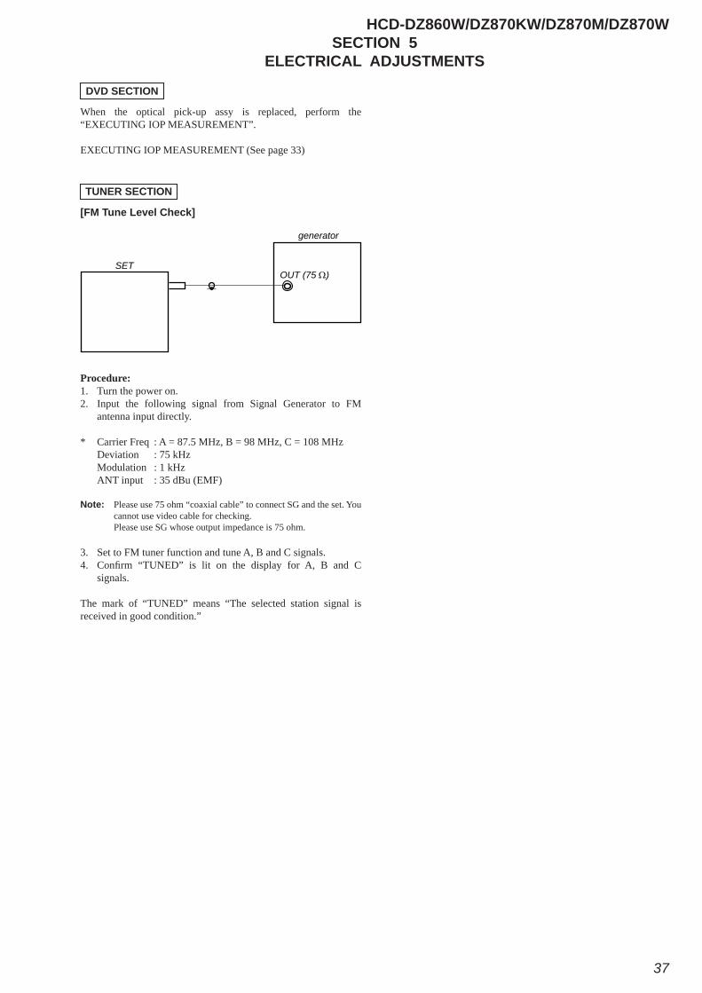
SECTION 5ELECTRICAL ADJUSTMENTS
When the optical pick-up assy is replaced, perform the “EXECUTING IOP MEASUREMENT”.
EXECUTING IOP MEASUREMENT (See page 33)
[FM Tune Level Check]
Procedure:1. Turn the power on.2. Input the following signal from Signal Generator to FM
antenna input directly. * Carrier Freq : A = 87.5 MHz, B = 98 MHz, C = 108 MHz Deviation : 75 kHz Modulation : 1 kHz ANT input : 35 dBu (EMF) Note: Please use 75 ohm “coaxial cable” to connect SG and the set. You
cannot use video cable for checking. Please use SG whose output impedance is 75 ohm. 3. Set to FM tuner function and tune A, B and C signals.4. Confi rm “TUNED” is lit on the display for A, B and C
signals. The mark of “TUNED” means “The selected station signal is received in good condition.”
DVD SECTION
TUNER SECTION
generator
OUT (75 Ω)SET
HCD-DZ860W/DZ870KW/DZ870M/DZ870W
38
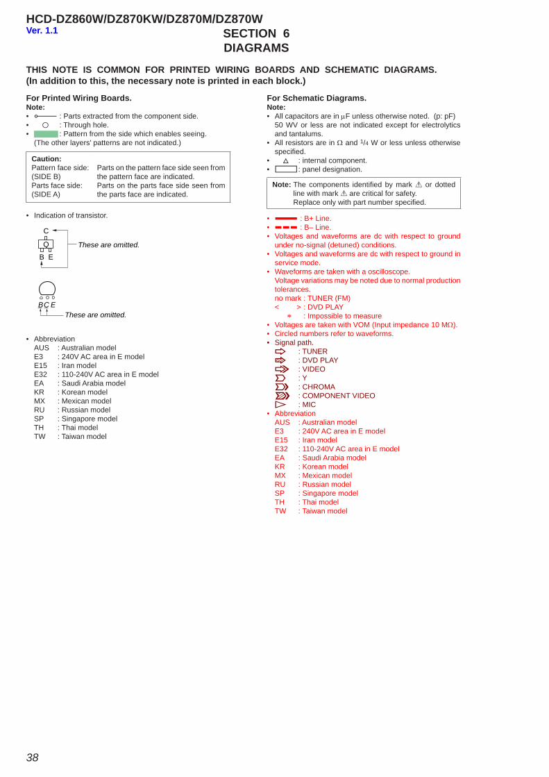
SECTION 6DIAGRAMS
For Schematic Diagrams.Note:• All capacitors are in μF unless otherwise noted. (p: pF) 50 WV or less are not indicated except for electrolytics
and tantalums.• All resistors are in Ω and 1/4 W or less unless otherwise
specifi ed.• f : internal component.• C : panel designation.
THIS NOTE IS COMMON FOR PRINTED WIRING BOARDS AND SCHEMATIC DIAGRAMS.(In addition to this, the necessary note is printed in each block.)
• A : B+ Line.• B : B– Line.• Voltages and waveforms are dc with respect to ground
under no-signal (detuned) conditions.• Voltages and waveforms are dc with respect to ground in
service mode.• Waveforms are taken with a oscilloscope. Voltage variations may be noted due to normal production
tolerances. no mark : TUNER (FM) < > : DVD PLAY * : Impossible to measure• Voltages are taken with VOM (Input impedance 10 MΩ).• Circled numbers refer to waveforms.• Signal path. F : TUNER J : DVD PLAY L : VIDEO E : Y a : CHROMA r : COMPONENT VIDEO N : MIC• Abbreviation AUS : Australian model E3 : 240V AC area in E model E15 : Iran model E32 : 110-240V AC area in E model EA : Saudi Arabia model KR : Korean model MX : Mexican model RU : Russian model SP : Singapore model TH : Thai model TW : Taiwan model
For Printed Wiring Boards.Note:• X : Parts extracted from the component side.• a : Through hole.• : Pattern from the side which enables seeing. (The other layers' patterns are not indicated.)
• Indication of transistor.
C
BThese are omitted.
E
Q
C EBThese are omitted.
Caution:Pattern face side:(SIDE B)Parts face side: (SIDE A)
Parts on the pattern face side seen from the pattern face are indicated.Parts on the parts face side seen from the parts face are indicated.
• Abbreviation AUS : Australian model E3 : 240V AC area in E model E15 : Iran model E32 : 110-240V AC area in E model EA : Saudi Arabia model KR : Korean model MX : Mexican model RU : Russian model SP : Singapore model TH : Thai model TW : Taiwan model
Note: The components identifi ed by mark 0 or dotted line with mark 0 are critical for safety.
Replace only with part number specifi ed.
Ver. 1.1
HCD-DZ860W/DZ870KW/DZ870M/DZ870W
HCD-DZ860W/DZ870KW/DZ870M/DZ870W
3939
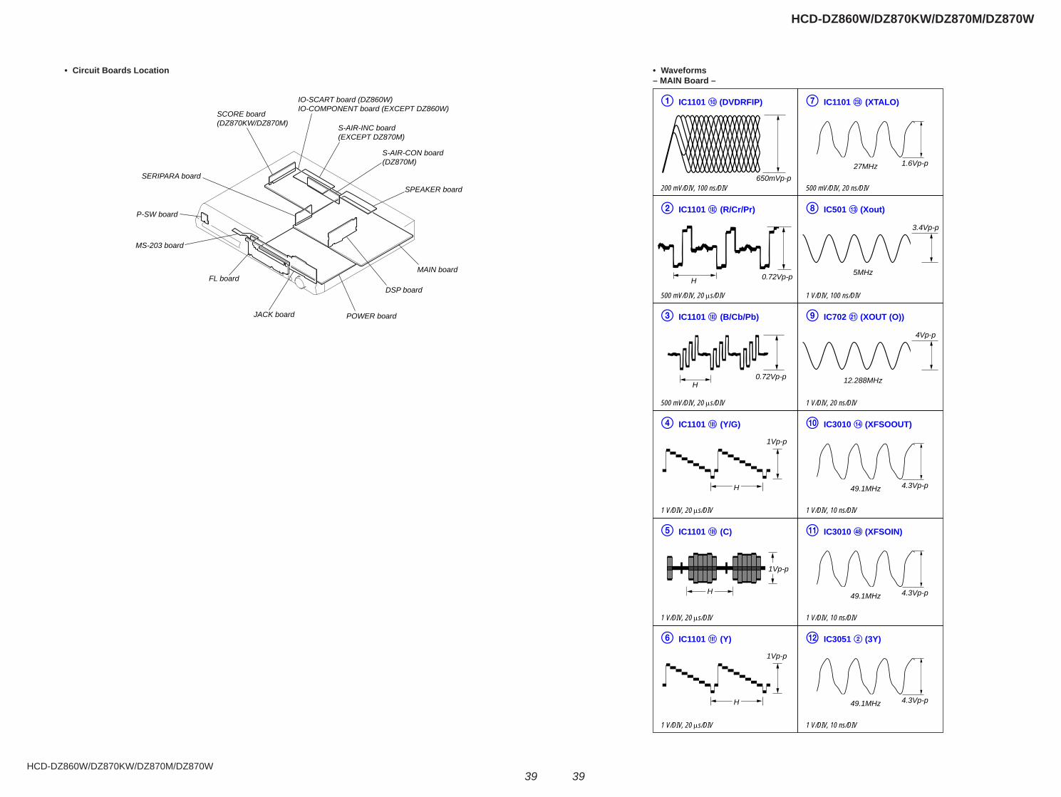
• Circuit Boards Location
SPEAKER board
S-AIR-CON board(DZ870M)
S-AIR-INC board(EXCEPT DZ870M)
IO-SCART board (DZ860W)IO-COMPONENT board (EXCEPT DZ860W)
SCORE board(DZ870KW/DZ870M)
MAIN board
DSP board
POWER board
MS-203 board
SERIPARA board
P-SW board
FL board
JACK board
• Waveforms– MAIN Board –
IC1101 (DVDRFIP)
200 mV/DIV, 100 ns/DIV
IC1101 (R/Cr/Pr)
500 mV/DIV, 20 μs/DIV
IC1101 (B/Cb/Pb)
500 mV/DIV, 20 μs/DIV
IC1101 (Y/G)
1 V/DIV, 20 μs/DIV
IC1101 (C)
1 V/DIV, 20 μs/DIV
IC1101 (Y)
1 V/DIV, 20 μs/DIV
IC1101 (XTALO)
500 mV/DIV, 20 ns/DIV
IC501 (Xout)
1 V/DIV, 100 ns/DIV
IC702 (XOUT (O))
1 V/DIV, 20 ns/DIV
IC3010 (XFSOOUT)
1 V/DIV, 10 ns/DIV
IC3010 (XFSOIN)
1 V/DIV, 10 ns/DIV
IC3051 (3Y)
1 V/DIV, 10 ns/DIV
0.72Vp-p
0.72Vp-pH
1Vp-p
H
1Vp-p
H
H
1Vp-p
4.3Vp-p49.1MHz
1.6Vp-p27MHz
4.3Vp-p49.1MHz
4.3Vp-p49.1MHz
3.4Vp-p
4Vp-p
5MHz
12.288MHz
650mVp-p
H
HCD-DZ860W/DZ870KW/DZ870M/DZ870W
HCD-DZ860W/DZ870KW/DZ870M/DZ870W
4040
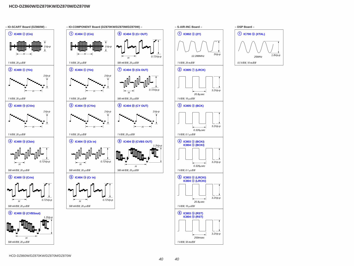
– IO-SCART Board (DZ860W) – – IO-COMPONENT Board (DZ870KW/DZ870M/DZ870W) – – S-AIR-INC Board – – DSP Board –
IC400 (Cin)
1 V/DIV, 20 μs/DIV
IC400 (Yin)
1 V/DIV, 20 μs/DIV
IC400 (CVin)
1 V/DIV, 20 μs/DIV
IC400 (Cbin)
500 mV/DIV, 20 μs/DIV
IC400 (Crin)
500 mV/DIV, 20 μs/DIV
IC400 (CVBSout)
500 mV/DIV, 20 μs/DIV
0.72Vp-p
0.72Vp-pH
1Vp-p
H
1Vp-p
H
H
1Vp-p
H
H
1.3Vp-p
IC404 (Cin)
1 V/DIV, 20 μs/DIV
IC404 (Yin)
1 V/DIV, 20 μs/DIV
IC404 (CYin)
1 V/DIV, 20 μs/DIV
IC404 (Cb in)
500 mV/DIV, 20 μs/DIV
IC404 (Cr in)
500 mV/DIV, 20 μs/DIV
IC404 (CY OUT)
1 V/DIV, 20 μs/DIV
IC404 (Cb OUT)
500 mV/DIV, 20 μs/DIV
IC404 (Cr OUT)
500 mV/DIV, 20 μs/DIV
IC404 (CVBS OUT)
500 mV/DIV, 20 μs/DIV
0.72Vp-p
0.72Vp-pH
1Vp-p
H
1Vp-p
H
H
1Vp-p
H
0.72Vp-p
0.72Vp-pH
1Vp-p
H
H
H
1.3Vp-p
IC802 (2Y)
1 V/DIV, 20 ns/DIV
IC805 (LRCK)
1 V/DIV, 10 μs/DIV
IC805 (BCK)
1 V/DIV, 0.1 μs/DIV
IC803 (BCKI) IC804 (BCKI)
1 V/DIV, 0.1 μs/DIV
IC803 (LRCKI) IC804 (LRCKI)
1 V/DIV, 10 μs/DIV
IC803 (RST) IC804 (RST)
1 V/DIV, 50 ms/DIV
3Vp-p12.288MHz
3.2Vp-p20.8μsec
3.2Vp-p0.326μsec
3.2Vp-p0.326μsec
3.2Vp-p20.8μsec
3.2Vp-p259msec
IC700 (XTAL)
0.5 V/DIV, 10 ns/DIV
1.8Vp-p25MHz
HCD-DZ860W/DZ870KW/DZ870M/DZ870W
HCD-DZ860W/DZ870KW/DZ870M/DZ870W
4141
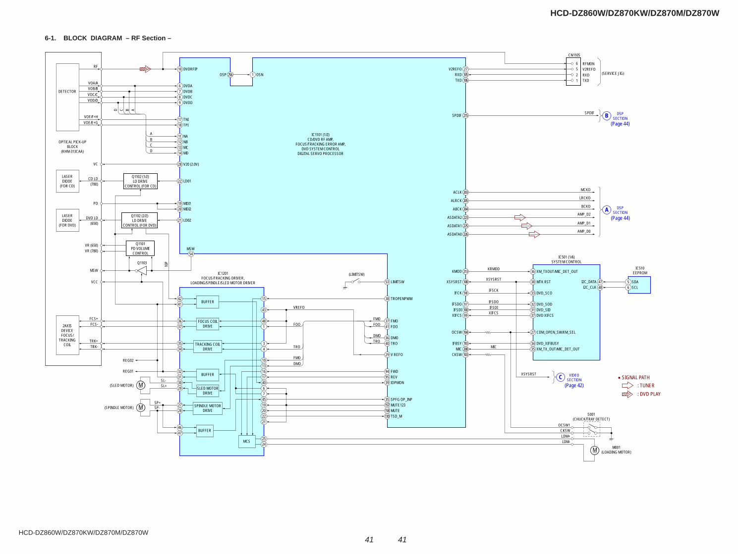
6-1. BLOCK DIAGRAM – RF Section –
RF
DETECTOR
LASERDIODE
(FOR CD)
OPTICAL PICK-UPBLOCK
(KHM-313CAA)
Q1102 (1/2)LD DRIVE
CONTROL (FOR CD)
DVDRFIP10OSN1OSP
V2REFO 27RXDTXD
DVDAVOA/AVOB/BVOC/CVOD/D
VOF/F+HVOE/E+G
VC
PD
CD LD(780)
6DVDB7DVDC8DVDD9
TNI17TPI
AABCD
BCD
18
NA11NB12MC13MD14
V20 (2.0V)28
LD0122
MDI119MDI220
LASERDIODE
(FOR DVD)
Q1102 (2/2)LD DRIVE
CONTROL (FOR DVD)
Q1101PD VOLUMECONTROL
IC1201FOCUS/TRACKING DRIVER,
LOADING/SPINDLE/SLED MOTOR DRIVER
IC1101 (1/2)CD/DVD RF AMP,
FOCUS/TRACKING ERROR AMP,DVD SYSTEM CONTROL
DIGITAL SERVO PROCESSOR
IC501 (1/6)SYSTEM CONTROL
XSYSRST
KRMOD
IFSCK
IFSDOIFSDIXIFCS
MIC
IC510EEPROM
(SERVICE JIG)
BUFFER
DVD LD
VR (650)VR (780)
MSW
Q1103
10P
VCC
(650)LD02
MSW
FOO
VREFO
TRO
FMODMO
21
TROPENPWM38
MTK RST
MCKO
LRCKO
BCKO
AMP_D2
AMP_D1
AMP_D0
38
TXDRXDV2REFORFMON
CN1105
1256
SDA5SCL6
DVD_SCO33
DVD_SOD32DVD_SID31DVD XIFCS37
CDM_OPEN_SW/XM_SEL27
DVD_XIFBUSY
XSYSRST
S001(CHUCK/TRAY DETECT)
M001(LOADING MOTOR)
OCSW1CKSWLDM+LDM-
34
98
FMO37FOO41
DMO36TRO
FMOFOO
DMOTRO 40
V REFO29
FWD94REV95IOPMON39
SPFG OP_INP35MUTE123MUTETSD_M
LIMITSW
(LIMITSW)
53
42
25
212220194576
4017161310
43
148
43
15
24
41
54
2AXISDEVICEFOCUS/
TRACKINGCOIL
(SLED MOTOR)
REG01
REG02
(SPINDLE MOTOR)
FCS+FCS-
TRK+TRK-
SP-SP+
SL-SL+
BUFFER4647
MCS
BUFFER32313029
SPINDLE MOTORDRIVE
2728
SLED MOTORDRIVE
FOCUS COILDRIVE
3637
TRACKING COILDRIVE
3534
MM
MM
130158157
105106
XSYSRST
IFCK
47I2C_DATA48I2C_CLK
99XIFCS
97IFSDO
108
OCSW 104
IFBSY 110XM_TX_OUT/MIC_DET_OUT35MIC 208
CKSW 103
IFSDI 100
256
XM_TXOUT/MIC_DET_OUT36213KMOD
ASDATA0 226
ASDATA1 225
ASDATA2 223
ABCK 204
ALRCK 205
ACLK 203
DSPSECTIONA
SPDIFSPDIF 215
VIDEOSECTIONC
DSPSECTIONB
M
• SIGNAL PATH: TUNER: DVD PLAY
(Page 44)
(Page 44)
(Page 42)
HCD-DZ860W/DZ870KW/DZ870M/DZ870W
HCD-DZ860W/DZ870KW/DZ870M/DZ870W
4242
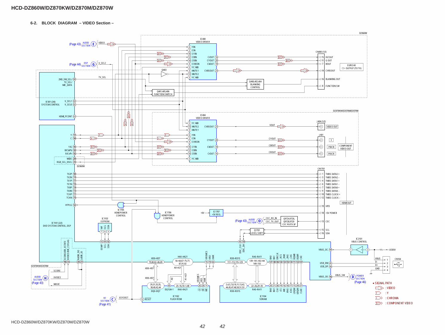
6-2. BLOCK DIAGRAM – VIDEO Section –
6 YIN2 CIN
10 CYIN12 CBIN14 CRIN
16CrOUT
802ND_XM_SEL/TV_SEL/
MIC_DATA
VIDEO
V_SEL2
TV_SEL
83V_SEL182V_SEL0
63HDMI_PCONT
210RGB_SEL_DSEL
DZ860W
DZ860W
DZ870KW/DZ870M/DZ870W
DZ870KW/DZ870M
191Y189C
185Y/G183B/Cb/Pb182R/Cr/Pr
209WIDE
180TX2P179TX2N177TX1P176TX1N174TX0P173TX0N171TCKP170TCKN
162HTPLG
20CYOUT18CbOUT
23CVBSOUT
16CrOUT
20CYOUT
18CbOUT
23CVBSOUT
CROUT
CYOUT
CBOUT
VOUT
Q400,402,404BLANKINGCONTROL
Q401,405,406FUNCTION SWITCH
Q403
IC404VIDEO DRIVER
IC400VIDEO DRIVER
CN400 (1/2)
J404 (1/2)
VIDEO OUT
J401
CN1701
4 CVBSIN5 YC MIX
6 YIN2 CIN
10 CYIN12 CBIN14 CRIN
4 CVBSIN
5 YC MIX
CEC_RX_INCEC_TX_OUT
3 MUTE1
3 MUTE1
13 MUTE2
13 MUTE25 YC MIX
5 YC MIX
7
8
16
19
1511
R/COUT
1 TMDS DATA2 +3 TMDS DATA2 –4 TMDS DATA1 +6 TMDS DATA1 –7 TMDS DATA0 +9 TMDS DATA0 –
10 TMDS CLOCK +12 TMDS CLOCK –
19 HPD
G OUTBOUT
CVBSOUT
BLANKING OUT
FUNCTION SW
Y
PB/CB
PR/CR
HDMI OUT
+6V
IC1103EEPROM
IC1705HDMI POWER
CONTROLIC1706
HDMI POWERCONTROL
IC1102FLASH ROM
IC1101 (2/2)DVD SYSTEM CONTROL, DSP
IC501 (2/6)SYSTEM CONTROL
IC1104SDRAM
IC1707+5V REG.
WF
EEW
P
SCOR
E/DI
R_XS
TATE
XVOI
CE/D
IR_C
SFLA
G
Rt/D
IR_D
OLt/
DIR_
DI
SCL
SDA
18 +5V POWER
13 CEC
15 SCL16 SDA
Q9724,9726,Q9728,9729
CEC RX/TX I/F
7
112
214198 231230
101 102DD
C_CL
K161
DDC_
DA159
CLKE
37
UDQM
39
LDQM
15
WE
11
OE
28
CE
2645
12
/CAS
17/R
AS18
/WE
16
/CS
19
CLK
38
BA1
21
BA0
20
CKE
147
DQM1
132
DQM0
111
_CAS
134
_RAS
135
_RW
E
133
_RCS
136
DRCL
K
146
BA1
138
BA0
137
XWR
66
XRD
78
XROM
CSXW
RXR
DXR
OMCS
A1–A
21
A0
76
SCL
6
SDA
5 Q1701LEVEL SHIFT
139–141,143,144149–155
2,4,5,7,8,10,11,13,42,44,45,47,48,50,51,53
117–113,119–129
22–26,29–35
RD0–RD15 RA0–RA11
RD0–RD15 RA0–RA11
56–64,67–75,77,87,91,92
29,31,33,35,38,40,42,44
79,80,82–86,89
25–16,10–1,48
HD0–HD7 HA0–HA21
A0–A21HD0–HD7
HD0–HD7
DQ0–DQ7 RA0–RA21DQ15/A-1
RESETXSYSRST
SCORE
XVOICE
MUSIC
CRFSECTION
HAUDIOSECTION
OAUDIOSECTION
EAUDIOSECTION
OUTPUT (TO TV)EURO AVGDSP
SECTION
COMPONENTVIDEO OUT
IC2101VBUS CONTROL
CN104
USB5V
1234
VBUSD-D+GND
196
VBUS_OC
USB_DM
197 1
45USB_DP 44
VBUS_OE VBUS_SW
3
POWERSECTIOND
• SIGNAL PATH: VIDEO: Y: CHROMA: COMPONENT VIDEO
(Page 43)
(Page 44)
(Page 43)
(Page 46)(Page 43)
(Page 41)
HCD-DZ860W/DZ870KW/DZ870M/DZ870W
HCD-DZ860W/DZ870KW/DZ870M/DZ870W
4343
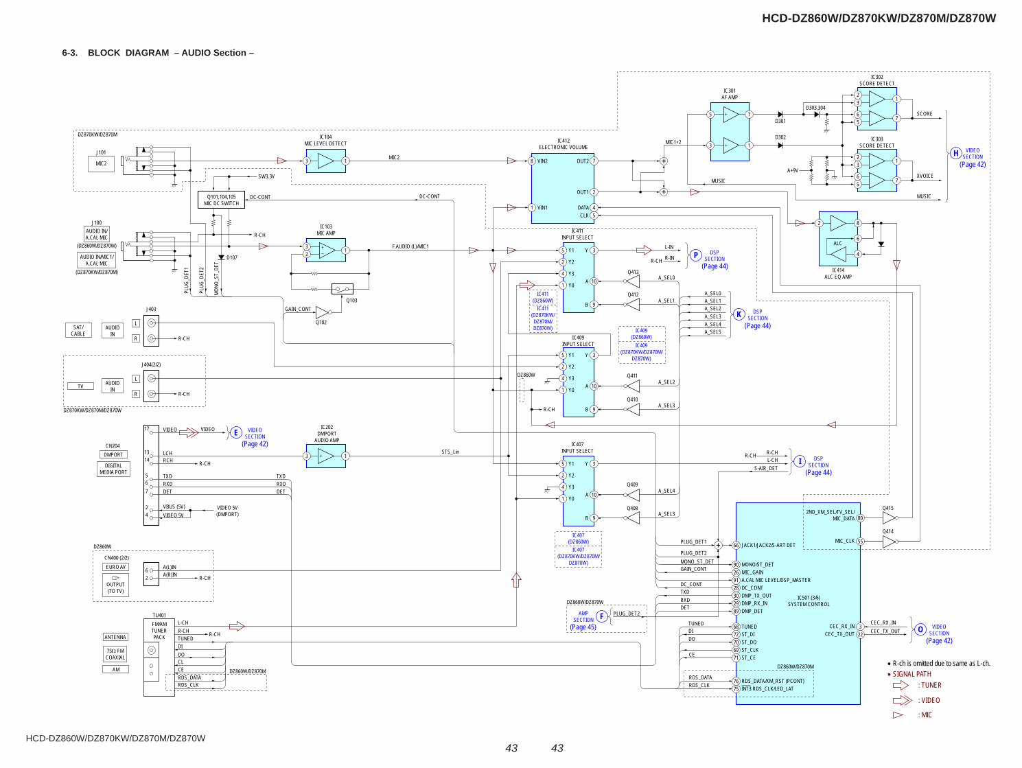
6-3. BLOCK DIAGRAM – AUDIO Section –
Q101,104,105MIC DC SWITCH
J100
SW3.3V
DC-CONT DC-CONT
F.AUDIO (L)/MIC1
STS_Lin
MIC2
R-CH
R-CH
R-CH
D107
Q102
Q103
Q413
D302
D301
D303,304
Q412
Q409
Q408
Q414
Q415
Y1 Y
GAIN_CONT
PLUG
_DET
1
PLUG
_DET
2
MONO
_ST_
DET
IC103MIC AMP
IC407INPUT SELECT
IC202DMPORT
AUDIO AMP
IC501 (3/6)SYSTEM CONTROL
AUDIO IN/A.CAL MIC
(DZ860W/DZ870W)
AUDIO IN/MIC1/A.CAL MIC
(DZ870KW/DZ870M)
J404(2/2)
CN204
CN400 (2/2)
TU401FM/AMTUNERPACK
TV
DMPORT
DIGITALMEDIA PORT
EURO AV
AM
DZ860W
DZ870KW/DZ870M/DZ870W
DZ860W/DZ870M
AUDIOIN
OUTPUT(TO TV)
32
IC104MIC LEVEL DETECT
3 1
3 1
VIDEO VIDEO
LCHRCH
VBUS (5V)
DETRXDTXD
DETRXDTXD
VIDEO 5V
A(L)INA(R)IN
L-CHR-CHTUNEDDIDOCLCERDS_DATARDS_CLK
VIDEO 5V(DMPORT)
1314
567
6
2
2
4
17
J101
MIC2
1
IC301AF AMP
IC412ELECTRONIC VOLUME
5 7
3 1
5 3
A 10
B 9
Y22
Y34
Y01
Y1 Y
IC409INPUT SELECT
DZ860W
5 3
A 10
B 9
Y22
Y34
Y01
Y1 Y
IC411INPUT SELECT
5
VIN11
VIN28 OUT2 7
CLK 5DATA
A+9V
4
OUT1 2
3
A 10
B 9
Y22
Y34
Y01
L
R
VIDEOSECTIONE
AMPSECTION F
R-CH
R-CH
INT3 RDS_CLK/LED_LAT75
CEC_RX_IN CEC_RX_IN3
MIC_CLK 55
2ND_XM_SEL/TV_SEL/MIC_DATA 80
CEC_TX_OUT CEC_TX_OUT22
75Ω FMCOAXIAL
ANTENNA
DZ860W/DZ870M
DZ860W/DZ870W
DZ870KW/DZ870M
RDS_DATA/XM_RST (PCONT)76
ST_CE71ST_CLK69ST_DO70ST_DI72TUNEDTUNED
DIDO
CE
RDS_DATARDS_CLK
68
DMP_TX_OUT30DC_CONT28A.CAL MIC LEVEL/DSP_MASTER91MIC_GAIN26MONO/ST_DETMONO_ST_DET
GAIN_CONT
DC_CONTTXDRXDDET
PLUG_DET1
PLUG_DET2
PLUG_DET2
A_SEL4
A_SEL3
R-CHR-CH
R-CH
L-CHS-AIR_DET
L-IN
R-IN
MIC1+2
R-CH
A_SEL0
XVOICE
MUSIC
MUSIC
A_SEL1A_SEL2A_SEL3A_SEL4A_SEL5
90
JACK1/JACK2/S-ART DET66
DMP_RX_IN29DMP_DET89
DSPSECTIONP
DSPSECTIONK
VIDEOSECTIONH
VIDEOSECTIONO
DSPSECTIONI
• R-ch is omitted due to same as L-ch.
R-CH
J403
SAT/CABLE
AUDIOIN
L
R
Q411
Q410
21
3
IC302SCORE DETECT
67
5
21
3
IC303SCORE DETECT
IC414ALC EQ AMP
67
5
2 8
6
4
SCORE
ALC
A_SEL3
A_SEL2
A_SEL0
A_SEL1
• SIGNAL PATH: TUNER
: VIDEO
: MIC
IC409(DZ870KW/DZ870M/
DZ870W)
IC409(DZ860W)
IC411(DZ870KW/DZ870M/DZ870W)
IC411(DZ860W)
IC407(DZ870KW/DZ870M/
DZ870W)
IC407(DZ860W)
(Page 42)
(Page 45)
(Page 42)
(Page 44)
(Page 44)
(Page 44)
(Page 42)
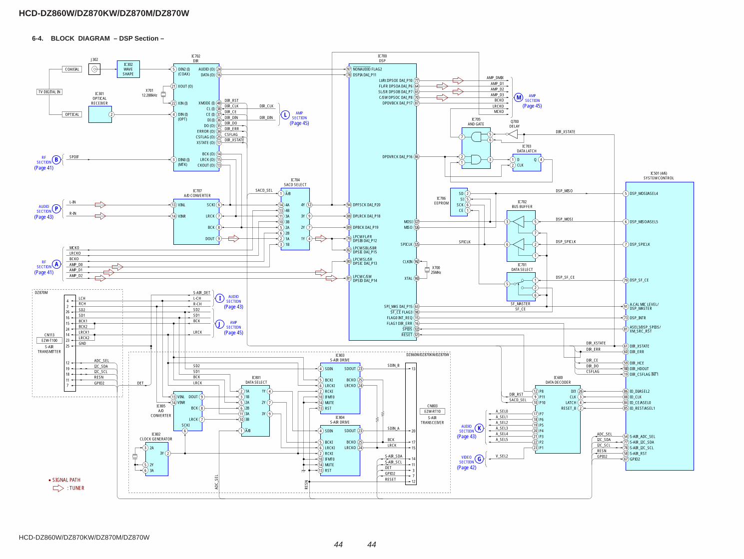
HCD-DZ860W/DZ870KW/DZ870M/DZ870W
HCD-DZ860W/DZ870KW/DZ870M/DZ870W
4444
6-4. BLOCK DIAGRAM – DSP Section –
DIN2 (I)(COAX)
5 AUDIO (O) 24DATA (O) 16
XMODE (I) 48CL (I) 38CE (I) 37DI (I) 36
DO (O) 35ERROR (O) 34
CSFLAG (O) 25XSTATE (O) 17
Lt/Rt DPSOE DAI_P10 AMP_DMIXAMP_D1AMP_D2AMP_D3
BCKOLRCKOMCKO
77FL/FR DPSOA DAI_P6 64SL/SR DPSOB DAI_P7 65C/SW DPSOC DAI_P8 70
DPDVBCK DAI_P17 87
DPDVRCK DAI_P16 86
SPI_MAS DAI_P15 63
SDOUT 23
BCKO 25LRCKO
2Y
24
SF_CE FLAG3 98FLAG0 INT_REQ 15FLAG1 DIR_ERR 16
SPIDS 122RESET 121
MOSI
56
BCK (O) 14LRCK (O) 15
CKOUT (O) 13
22
21X701
12.288kHz
X70025MHz
XIN (I) DIR_RSTDIR_CLKDIR_CEDIR_DIN
DIR_CLK
DIR_DINDIR_DODIR_ERR
DIR_XSTATECSFLAG
SCKI 6
LRCK 7
BCK 8
DOUT 9
4Y 12
3Y 9
2Y 7
1Y 4
DPFSCK DAI_P20
DCLK
94
DSP_MOSI/ASEL45
DSP_MISO/ASEL56
DSP_SPICLKDSP_SPICLK
DSP_MISO
DIR_XSTATE
7
NONAUDIO FLAG297DSPIA DAI_P1178
DPLRCK DAI_P1888
DPBCK DAI_P1989
LPCM FL/FRDPSIB DAI_P1279
LPCM SBL/SBRDPSIE DAI_P1582
LPCM SL/SRDPSIC DAI_P1380
LPCM C/SWDPSID DAI_P1481
13 VINL 14 4A
1 A/B
13 4B11 3A10 3B5 2A6 2B2 1A3 1B
4 SDIN
5 BCKI
LRCK
LRCK
4226161524142325
711181912
6 LRCKI2 RCKI
10 IFMT0147
DOUT 9
BCK 8
LRCKSCKI
7
3Y 2
3Y 9
1Y 41A21B3VINL13
VINR14
6
2A52B63A113B10
A/B1
MUTE13 RST
3 DIN0 (I)(MTK)
DIN (I)(OPT)
XOUT (O)
J302
IC301OPTICAL
RECEIVER
IC702DIR
IC700DSP
IC707A/D CONVERTER
IC704SACD SELECT
IC703DATA LATCH
IC501 (4/6)SYSTEM CONTROL
IC702BUS BUFFER
IC803S-AIR DRIVE
IC801DATA SELECT
IC802CLOCK GENERATOR
IC805A/D
CONVERTER
SDOUT 23
BCKO 25LRCKO 24
4 SDIN
5 BCKI6 LRCKI2 RCKI
10 IFMT014 MUTE13 RST
IC804S-AIR DRIVE
IC705AND GATE Q700
DELAY
IC701DATA SELECT
IC600DATA DECODER
IC706EEPROM
COAXIAL
OPTICAL
SPDIF
42
IC302WAVESHAPE
TV DIGITAL IN
EZW-T100CN113
DZ870M
S-AIRTRANSMITTER
EZW-RT10CN803
S-AIRTRANSCEIVER
L-IN
MCKOLRCKOBCKOAMP_D0AMP_D1AMP_D2
14 VINRR-IN
RFSECTION B
AUDIOSECTION P
RFSECTION A
AMPSECTIONL
AMPSECTIONM
AUDIOSECTION K
AMPSECTIONJ
AUDIOSECTIONI
7
3
2
1 Q
SD5SI6SCK1CE
42
3 5
7
21
6
5
2
1
1
2
6
127
SPICLK
CLKIN
XTAL
SPICLK
DIR_XSTATEDIR_ERR
DIR_CEDIR_DOCSFLAG
ADC_SELI2C_SDAI2C_SCLRESNGPIO2
DIR_RST
SDIN_B13
SACD_SEL
SACD_SEL
A_SEL0
125
MISO 126
143
142
DSP_SF_CEDSP_SF_CE
SF_MASTERSF_CE
79
A.CAL MIC LEVEL/DSP_MASTER91
DSP_INTR73
DIR_XSTATE61DIR_ERR60
DIR_HCE59DIR_HDOUT100DIR_CSFLAG INT119
IO_DI/ASEL286IO_CLK88IO_CE/ASEL084
P812P119P1010
P717P618P519P420P321P222P123
IO_REST/ASEL1
DI1CLK
LATCHRESET_B 85
26342
S-AIR_ADC_SEL54S-AIR_I2C_SDA77S-AIR_I2C_SCL78S-AIR_RST58GPIO267
ASEL3/DSP_SPIDS/XM_SRC_RST81
A_SEL1A_SEL2A_SEL3A_SEL4A_SEL5
V_SEL2VIDEOSECTION G
SDIN_A
S-AIR_SDAS-AIR_SCL
GPIO2RESET
RESN
ADC_
SEL
DET
20
BCK 17LRCK 15
141137
12
5
3
2Y6 3A
2A
BCK
BCK
SD1SD2
SD1SD2
R-CHL-CHS-AIR_DET
ADC_SEL
LCHRCHSD2SD1BCK1BCK2LRCK1LRCK2GND
I2C_SDAI2C_SCLRESNGPIO2 DET
• SIGNAL PATH: TUNER
DZ860W/DZ870KW/DZ870W
DSP_MOSI
(Page 41)
(Page 41)
(Page 45)
(Page 43)
(Page 45)
(Page 42)
(Page 43)
(Page 45)
(Page 43)

HCD-DZ860W/DZ870KW/DZ870M/DZ870W
HCD-DZ860W/DZ870KW/DZ870M/DZ870W
4545
14 PWM_B
6 PWM_A
5
4
RESET
SD
OUT_B
31
31
2
6
DATA
36 XFSIIN
AMP_D1 AMP_D3
DIR_CLKDIR_DIN
AMP_D2AMP_D3 MCK0
BCK0LRCK0
OVF2SCDTSHIFTLAT3INIT
SOFTMUTE
AMP_D1
AMP_D2
MCK0BCK0LRCK0
OVFSCDTSHIFTLAT1INIT
SOFTMUTE
MCK0BCK0LRCK0
SCDTSHIFTLAT2INIT
SOFTMUTE
PLUG_DET2
BCKO
LRCKO
MCKOAMP_DMIX
BCK
LRCK
SD1
SD2
30 BCK29 LRCK25 OVF FLAGL24 OVF FLAGR21 SCDT22 SCSHIFT23 SCLATCH27 INIT
19 SOFTMUTE
OUTR1(+)
4OUTR2(–)
11OUTL1(+)
9OUTL2(–)
48XFS0IN
38FS0I
25-
2728-
30OUT_A
LPFSUBWOOFER
TB3901
TB101
SPEAKER
CENTER
PHONESJ101
IC3400DIGITAL POWER AMP
14 PWM_B
6 PWM_A
5
4
RESET SD
OUT_B 25-
2728-
30OUT_AIC3500
DIGITAL POWER AMP
PLUG DET2
DZ860W/DZ870W
DZ860W/DZ870KW/DZ870W
DZ860W/DZ870KW/DZ870W
DZ870M
DZ870M
DZ860W/DZ870W
HPMUTE Q107,109,Q106,108
MUTE
Q3081H/P MUTE
DRIVE
L
R
IC3001HEADPHONE AMP
LPF
Q3251,3252DC BALANCE
DETECT
D3551
6 PWM_A
14 PWM_B
5
4
RESET
SD
OUT_B 25-
2728-
30OUT_A
LPF
IC3300DIGITAL POWER AMP
LPF
Q3301,3302DC BALANCE
DETECT
14 PWM_B
HP
HP
HP
HP
WF
WF
C
C
FR
FR
FL
FL
SR
SR
SL
SL
6 PWM_A
5
4
RESET
SD
OUT_B 25-
2728-
30OUT_A
LPF
IC3100DIGITAL POWER AMP
LPF
Q3101,3102DC BALANCE
DETECT
6 PWM_A
14 PWM_B
5
4
RESET
SD
OUT_A 28-
3025-
27OUT_B
LPF
IC3150DIGITAL POWER AMP
IC3051CLOCK
OSCILLATOR
LPF
Q3151,3152DC BALANCE
DETECT
14 PWM_B
6 PWM_A
5
4
RESET
SD
OUT_B 25-
2728-
30OUT_A
LPF
IC3200DIGITAL POWER AMP
IC3020S-MASTER PROCESSOR
IC3010S-MASTER PROCESSOR
IC501 (5/6)SYSTEM CONTROL
IC3030S-MASTER PROCESSOR
LPF
Q3401,3402DC BALANCE
DETECT
6 PWM_A
14 PWM_B
5
4
RESET
SD
OUT_A 28-
3025-
27OUT_B
M+14V
LPF
IC3250DIGITAL POWER AMP
LPF
Q3202,3201DC BALANCE
DETECT
Q3551DC BALANCE
PROTECT
Q3552 – 3555B+ DOWN PROTECT
D3552
EN
+31V
Q631,632BUFFER
FANDRIVE
Q3000 – 3002
31
6
DATA
36 XFSIIN30 BCK29 LRCK25 OVF FLAGL24 OVF FLAGR21 SCDT22 SCSHIFT23 SCLATCH27 INIT
19 SOFTMUTE
2
15
6
OUTR1(+)
41HPOUTR1
39HPOUTR2
45HPOUTL1
43HPOUTL2
53HP_MUTE
52
1DAMP_SCDT/DIR_DIN2DAMP_SHIFT/DIR_CLK65DAMP LATCH156DAMP LATCH249DAMP LATCH350DAMP INIT51DAMP SOFT MUTE44OVERFLOW145OVERFLOW2
HPMUTESCDTSHIFTLAT1LAT2LAT3INIT
SOFTMUTEOVF
OVF2
EN
DIAG
DC-DET
42DRIVE RST(EN)
43SD(DIAG)/PVDD_DET
57DC_DET
4OUTR2(–)
11OUTL1(+)
9OUTL2(–)
48XFS0IN
14XFS0OUT
X305149.1MHZ
38FS0I37FS0CKOUT
316
DATA
IC3003DATA SELECT
36 XFSIIN30 BCK29 LRCK25 OVF FLAGL21 SCDT22 SCSHIFT23 SCLATCH27 INIT
19 SOFTMUTE24 OVF FLAGR
OUTR1(+)
4OUTR2(–)
11OUTL1(+)
9OUTL2(–)
48XFS0IN
14XFS0OUT
38FS0I
57
6
(+)
(–)
(–)
(+)
FRONT R
FRONT L
SPEAKER
SPEAKER
FRONT R
FRONT L
(+)
(–)
(+)
(–)
SUR R(+)
(–)
SUR L(+)
(–)
(+)
(–)
(+)
(–)
FAN3001DC FAN
N POWERSECTIONFAUDIO
SECTION
15
13X5015MHz
M_ST
Xin
Xout
M
J
DSPSECTION
DSPSECTION
• SIGNAL PATH: TUNER
LDSPSECTION
LPF
LPF
SHIFTSCDT
6-5. BLOCK DIAGRAM – AMP Section –
(Page 44)
(Page 44)
(Page 44)
(Page 43) (Page 46)
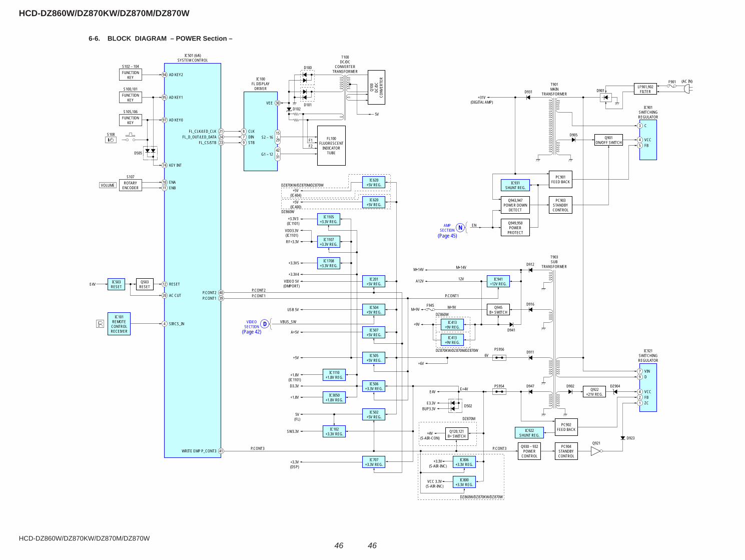
HCD-DZ860W/DZ870KW/DZ870M/DZ870W
HCD-DZ860W/DZ870KW/DZ870M/DZ870W
4646
6-6. BLOCK DIAGRAM – POWER Section –
94 AD KEY2
21FL_CLK/LED_CLK
30VEE
F1S2 – 16 FL100
FLUORESCENTINDICATOR
TUBE
T100DC/DC
CONVERTERTRANSFORMER
T901MAIN
TRANSFORMERD931+31V
(DIGITAL AMP)
D901
D905
T903SUB
TRANSFORMER
Q100
DC/D
CCO
NVER
TER
D100
D101D102
24FL_D_OUT/LED_DATA23
FUNCTIONKEY
S102 – 104
IC501 (6/6)SYSTEM CONTROL
IC100FL DISPLAY
DRIVER
95 AD KEY1FUNCTIONKEY
S100,101
10 ENAROTARYENCODER
S107
VOLUME 11 ENB
12 RESETE4V
20 AC CUT
4 SIRCS_IN
97 AD KEY0
7 VIN
4 VCCQ922+21V REG.
PC902FEED BACK
PC904STANDBYCONTROL
Q930 – 932POWER
CONTROL
Q120,121B+ SWITCH
IC922SHUNT REG.
IC921SWITCHINGREGULATOR
IC506+3.3V REG.
IC505+5V REG.
IC507+5V REG.
IC504+5V REG.
IC201+5V REG.
IC620+5V REG.
IC620+5V REG. IC931
SHUNT REG.
IC1105+3.3V REG.
IC1107+3.3V REG.
IC1708+3.3V REG.
IC502+5V REG.
IC707+3.3V REG.
IC102+3.3V REG.
IC3050+1.8V REG.
D902
D923Q921
D947
D502
PS954
P.CONT3P.CONT3
E4V E+4V
6V
+6V
E3.3VBUP3.3V
+4V(S-AIR-CON)
DZ904
2 FB1 ZC
9 D
3 C
4 VCC
IC901SWITCHINGREGULATOR
F901LF901,902
FILTER
PC901FEED BACK
PC903STANDBYCONTROL
Q943,947POWER DOWN
DETECT
Q949,950POWER
PROTECT
EN
5 FB
8 CLK7 DIN9 STB
FUNCTIONKEY
S105,106
D505
74 KEY INT
/S108 15 –
29
G1 – 12
DZ870KW/DZ870M/DZ870W
DZ860W
42 –
31
F2
5V
FL_CS/STB
40P.CONT239P.CONT1
P.CONT2
+3.3V5
+3.3V4
USB 5V
VBUS_SW
A+5V
+5V
D3.3V
+1.8V
5V(FL)
SW3.3V
+3.3V(DSP)
VIDEO 5V(DMPORT)
+1.8V(IC1101)
+5V(IC400)
+5V(IC404)
+3.3V3(IC1101)
VDD3.3V(IC1101)RF+3.3V
P.CONT1
41WRITE EMP P_CONT3
Q503RESET
IC503RESET
IC101REMOTE
CONTROLRECEIVER
D911PS956
D916
D941
F945 Q945B+ SWITCH
D912M+14V
M+9V
P.CONT1
12V
M+14V
M+9V
+9V
A12V IC941+12V REG.
IC413+9V REG.
IC1110+1.8V REG.
IC413+9V REG.
(AC IN)
Q901ON/OFF SWITCH
NAMPSECTION
DVIDEOSECTION
DZ870M
DZ860W/DZ870KW/DZ870W
+3.3V(S-AIR-INC)
IC806+3.3V REG.
VCC 3.3V(S-AIR-INC)
IC800+3.3V REG.
DZ870KW/DZ870M/DZ870W
DZ860W
(Page 42)
(Page 45)

HCD-DZ860W/DZ870KW/DZ870M/DZ870W
HCD-DZ860W/DZ870KW/DZ870M/DZ870W
4747
1234567891011121314
A
B
C
D
E
F
G
H
I
J
MAIN BOARD (SIDE A)
13
54
13(13)1-875-158-
DZ870KW/DZ870M/DZ870W
DZ870KW/DZ870M
DZ860W/DZ870KW/DZ870W
DZ870M
DZ870M/AEP,UK,MX,E32,KR,E3,E15,AUS MODEL
SP,TH,TW,E3,E15,AUS,RU,E32,KR,MX MODEL
DZ870KW/DZ870M
DZ860W
DZ870KW
DZ870KW/DZ870M
DZ870KW/DZ870M
DZ870KW/DZ870M
DZ860/DZ870W
OPTICALPICK-UP
DZ870M
DZ860W
DZ870KW
DZ870KWDZ860W/DZ870W
MS-203BOARDCN001
Z
J
IO-SCARTBOARDCN401
IO-COMPONENTBOARDCN402
I
JACKBOARDCN103
NDSP
BOARDCN701
V
IO-COMPONENTBOARDCN416
IO-SCARTBOARDCN405
M
L
IO-COMPONENTBOARDCN406
M
IO-COMPONENTBOARDCN408
M
IC33
00IC
3250
IC32
00IC
3150IC
3050
IC30
03IC
3001
IC704
IC50
7
IC50
1
IC50
3
IC51
0
IC502
IC31
00
IC3020
IC3030
IC30
10
IC30
51
IC2101
IC702
IC11
10
IC1101
IC17
06
IC1708IC1705
IC1104
IC1103IC302
IC1102
IC202
IC707
IC12
01
IC1107IC1105
IC34
00IC
3500
IC17
07
1 19
BE
BE
118
241
2548
58 1
4
I O
13121
2
BE
8
1 4
5
BE
BE
BE
145
8
BE
BE
12
4 5
BE
BE
191
182
B EB EB E
BE
BE
112
1348
24
2536
37
19 118 2
1 9
BE
BEBE
BE
B E B E
BE
BE
BE
BE
481 12
13
24
253637
58 1
4
1 8
916
8 1
5 4
178
14B
E
2 241 23
B E
BE
37 48
3625
24 13
121
C3058
C1118
R3225
R3031
C3059
C1119
CN1701
R3226
R3032
R3227
R3033
R3034
C325
0
R3035
ICT5
62
R3037
ICT5
63
C325
4
C3060
ICT564
C112
0
R214
Q325
1
ICT5
65
C112
1
R215
Q325
2
ICT5
66
C112
2
ICT5
67
C112
3
C325
8
ICT5
68
JL3098
C112
4
R3425
R342
6
R342
7
R3041
Q170
1
R3042
R3043R3044
ICT5
70
JL1160
CN204
DMPORTCN204
HDMI OUTCN1701DC 5V
0.7A MAX
ICT5
71
ICT5
72
C326
3
R1107
R3047R1
108
R110
9
R3049
C307
2
C1132
C307
3
C11331 64
65
128
129192
193
256R2
27
R228
C1135
R229
C113
6
R613
C1137C1138
R111
0
R3050
C1139
R1111
R3052
R1112
R3053
R1113
TP3110
R305
4
R111
4
R230
R305
5
R1115
R231
R111
6
R305
7
R111
7
R111
8
C3083
C3084
CN60
4
SL30
01
R3251
Q308
1
C308
5
C1145
CN60
5R622
R3252
C308
6
CN60
6R623C3087
C1147
R624
R3254
C3088
R1120
C1148
R625
R306
1
TP3311
C172
5
R1121
C1726
R626
R325
7
R1123
R1124
C1728
ICT591
C1729
R629
ICT5
92
R3067R3068
C3092
C1152
C3093
C1153
TP35
10
C1730
TP3129
R631
C1731
R632
C1732
R633
C1733
R634
C1734
R326
5
R635
R637
R3074
TP31
30
R639
R3075
TP3131
R113
5
R3076
R1136
R307
7 R30
78
R3079
R1139
C2101
TP3136
C210
3
R643
C220
R3275
C2109
R3276
R114
2
R3277
C223
R648
R3085
R3086
R1146
R3087
C227
R3088
C2110
R3089
C229
R652
R3090
C230
R309
1
R115
1
C231
R309
2
C232
R309
3
R657
TP3150
R309
4
TP70
0
R4805
R1156
C237
R3098 R3099
R1159
C118
2
C118
3
C118
4
R660
C1186
R663
R1160
R664
R1161
R2101C241
JL3101
R174
2
JL3104
C213
0
IC21
01
C119
2 1
1
3
3
4
4
5
5
JL3107
R174
7
C1193
R174
8
C1195
TP52
8
R211
0
C119
8
TP52
9
R2111R2112
JL3110
R211
4
R2115
JL31
12
R2116
R175
2
JL3113JL3114
JL31
15
4
4
5
53
3
1
1
31
13
4 5
JL3116JL3117
R681
R682
R212
1
R685R686
R1183
R212
3
R687
R1184
R688
CL1201
R1185
R212
7
CL1204
R212
8
CL1205CL
1206
CL12
07
LP30
00
CL12
08
TP54
8
TP54
9
R1191
Q503
R213
3
R1193
R698
R699
R2135
CL12
13
C310
0
SL50
1
SL50
2
SL50
3
SL50
4
C310
4
Q310
1Q3
102
ICL5
22
RB1103
C310
8
RB1104
RB1105RB1106
RB1107
C330
0
RB1108
RB11
09
R1783
C330
4
R1784
Q330
1
R1785
Q330
2
R178
6
C311
3C3
308
RB11
10
RB1111
RB11
12
RB11
13
C350
0
RB1114
RB1115
C350
4
R2154
C331
3118 19
36118 19
36
118 19
36
118 19
36
118 19
36
118 19
36
118 19
36
118 19
36
C350
8
TP573 C3124TP574
C312
5
C3126
C312
7C3
128
C312
9
R3101R3102
C351
3
R3104
R310
7
R2167
R2168
R274
6
R3301
R3302
CN12
02
R330
4
R330
7
R311
5
R217
6
R217
7
R3501
X1101
R3502
C120
3
R350
4
C120
5 C12
06
R350
7
C120
8
R331
5
C120
9
R3125
R312
6
R312
7
R2187
FB50
8
C315
0
C1210
X3051
C121
1C1212
C1213
C315
4
C1214
R351
5
Q315
1
C121
5
Q315
2
FB51
0
C315
8
C121
8
R3901
R332
5
C121
9
R2191
R390
2
R332
6
R2192
R3327
R2193R5
04
R2194
JL3385
R390
5
R505
R219
5
JL3386
R3906
R506
R507
C122
0
R509
C1221
CN43
01
TP3002
C1222
FB1106
CN43
02
C316
3
C122
3
FB1108
C122
4
R318
TP30
05
TP30
06
R510
R511
R512
C355
3
R513
R514
R120
4
R515
Q355
1
C3556
Q355
2
R516
R1206
R391
7
Q3553
R120
7
R3918
R1208
Q355
4
R3919
R519
R120
9
C1231
Q355
5
C1232
C123
3
TP3015
CN502
R713
R3920
R121
0
CN504
R3921
R315
1
C356
1
R522
R315
2
R1212
R717
TP32
10
R718
R524
R3154
R1214
R719
R121
5
R121
6
R315
7
R529
R1219
TP3022
CN70
3
TP30
24
R721
LP50
1
R722
TP3026R723
TP3410
R724
R1220
R725
TP3029
R122
1
R532
R122
2
R727
R122
3
R728
R1224
R729
R316
5
R1225
R536
R122
6
D355
2
R537
R122
7
TP30
30
R122
8
LP70
1
R355
2
TP3032
R730
R355
4
R731
L305
1
R355
5
TP32
29
R355
6
R732 TP3036
R733
L305
3
R3558
R734
L3054
Q972
4
R1230
R1231
R355
9
R541
R736
R542
Q9726
R543
R1233
R738
TP32
30
Q9728
C509
R739
R3175
TP3231
Q9729
R3176
R546
R547
R3177
R548
R356
0
R356
1
R549
TP32
36
R356
2R356
3
C510
R740
R741
FB75
1
C511
D971
2
C512
C707
R743
C708
L170
1
C516
R552
L170
2
L170
3
L170
4
R1246R1247
X701
C520
CL21
8
C521
R751
CL21
9C5
22
R752
C523
13 4
5
C718
R754
C719
R755
R561R5
62
R757
TP32
50
R564
R125
4
CL22
0
R759
R565
CL22
1 R566
FB21
02
R567
R568
C721
R569
C723
C724
R760
R9920
C725
C531
R761
R762
C727
R9924
R572
R573
R992
8R9
929
R472
1
JL30
10
JL3011
JL3013
JL3014
JL30
15
R771
JL30
16
JL3017
JL30
18
R774
R993
4
JL3019
R775
R9935
R776
R583
R778
FB21
20
R584
FB21
21FB
2122
R587
JL30
20
R588
FB21
24
JL30
21
FB2125
CL11
01
R589
JL30
22
JL30
23
JL3024
JL30
25
R994
1
CL11
05
L210
1
JL30
26JL
3027
JL30
28
CL11
08
R590
JL30
29
R994
5
R788
CL13
01
C997
2
R596
CL13
02
R597
CL13
03
JL3030
CL11
10
R598
CL13
04
JL30
31
R599
CL13
05
JL30
32
C752
CL11
12
JL30
33
CL11
13
JL30
34
R790CL
1114
L200
CN4302(17P)
CN4301(19P)
D501 JL
3035
R791
CL11
15
JL3036
CL11
16
JL3037
CL11
17
C300
3
R793
JL30
38
CL11
18
Q3001
JL30
39
R795
Q3002
C300
8
R798
C320
0
JL3040
CL11
21
JL30
41
JL3042
JL30
43C3
204
JL30
44
Q320
1
JL30
45
C571
Q320
2
JL3046
CL17
02
JL30
47
C320
8
ICT5
18
JL30
48
C574
JL3049
C340
0C3
404
ICT5
20
JL30
50
Q340
1
JL3051
Q340
2
JL3052
C321
3
JL3053
C340
8
JL3054
C774
JL3055
ICT5
26
JL3056
JL3057
JL3058
JL3059
R300
1C3
413
JL3060
JL3062
ICT5
37
R320
1
CN1101
Q631
R3202
Q632
R320
4
R3011
R3012
R320
7
R3013
R3014R3015
R3017
R3401
C1101
R3402
R3404
ICT5
49
C1105
Q1101
Q110
2
R340
7
Q1103
R321
5
R3021R3022
R3023R3024
CL21
01
R3026
CL21
02
CL21
03
37 48
3625
24 13
121
C1110
JL3085
C1111
C3052
JL3086
C1112
C305
3
JL3087
C1113
CL21
07
CL21
08
R341
5
C305
5
ICT5
59
CL21
09
C305
7
C1117
1
12
132425
3637 48
ICT558
CN604(13P)
CN605(11P)
CN605(11P)
CN606(9P)
6-7. PRINTED WIRING BOARD – MAIN Board (Side A) – • : Uses unleaded solder.• See page 39 for Circuit Boards Location.When IC510 and IC1103 on the Main board are damaged, exchange the new Main board for the Main board which IC damaged.
Ref. No. Location• Semiconductor Location
D501 H-11 D3552 B-3 D9712 C-7
IC202 C-11 IC302 B-5 IC501 H-10 IC502 I-11 IC503 G-11 IC507 I-9 IC510 I-11 IC702 F-7 IC704 H-7 IC707 F-11 IC1101 C-8 IC1102 D-7 IC1103 C-7 IC1104 B-8 IC1105 D-11 IC1107 D-10 IC1110 B-10 IC1201 E-10 IC1705 B-8 IC1706 B-9 IC1707 B-9 IC1708 B-9 IC2101 E-7 IC3001 H-6 IC3003 G-6 IC3010 F-5 IC3020 E-5 IC3030 D-5 IC3050 H-6 IC3051 G-5 IC3100 H-4 IC3150 H-4 IC3200 G-4
Ref. No. Location IC3250 F-4 IC3300 E-4 IC3400 D-4 IC3500 C-4
Q503 H-11 Q631 H-5 Q632 H-5 Q1101 E-7 Q1102 E-10 Q1103 E-7 Q1701 C-8 Q3001 C-4 Q3002 C-4 Q3081 H-6 Q3101 G-1 Q3102 G-1 Q3151 H-1 Q3152 H-1 Q3201 F-1 Q3202 F-1 Q3251 D-1 Q3252 D-1 Q3301 E-1 Q3302 E-1 Q3401 F-1 Q3402 F-1 Q3551 B-2 Q3552 B-2 Q3553 B-3 Q3554 B-3 Q3555 B-3 Q9724 D-7 Q9726 C-6 Q9728 C-7 Q9729 C-6
(Page 62)
(Page 58)
(Page 60)
(Page 60)
(Page 60)
(Page 64)
(Page 58)
(Page 60)
(Page 66)
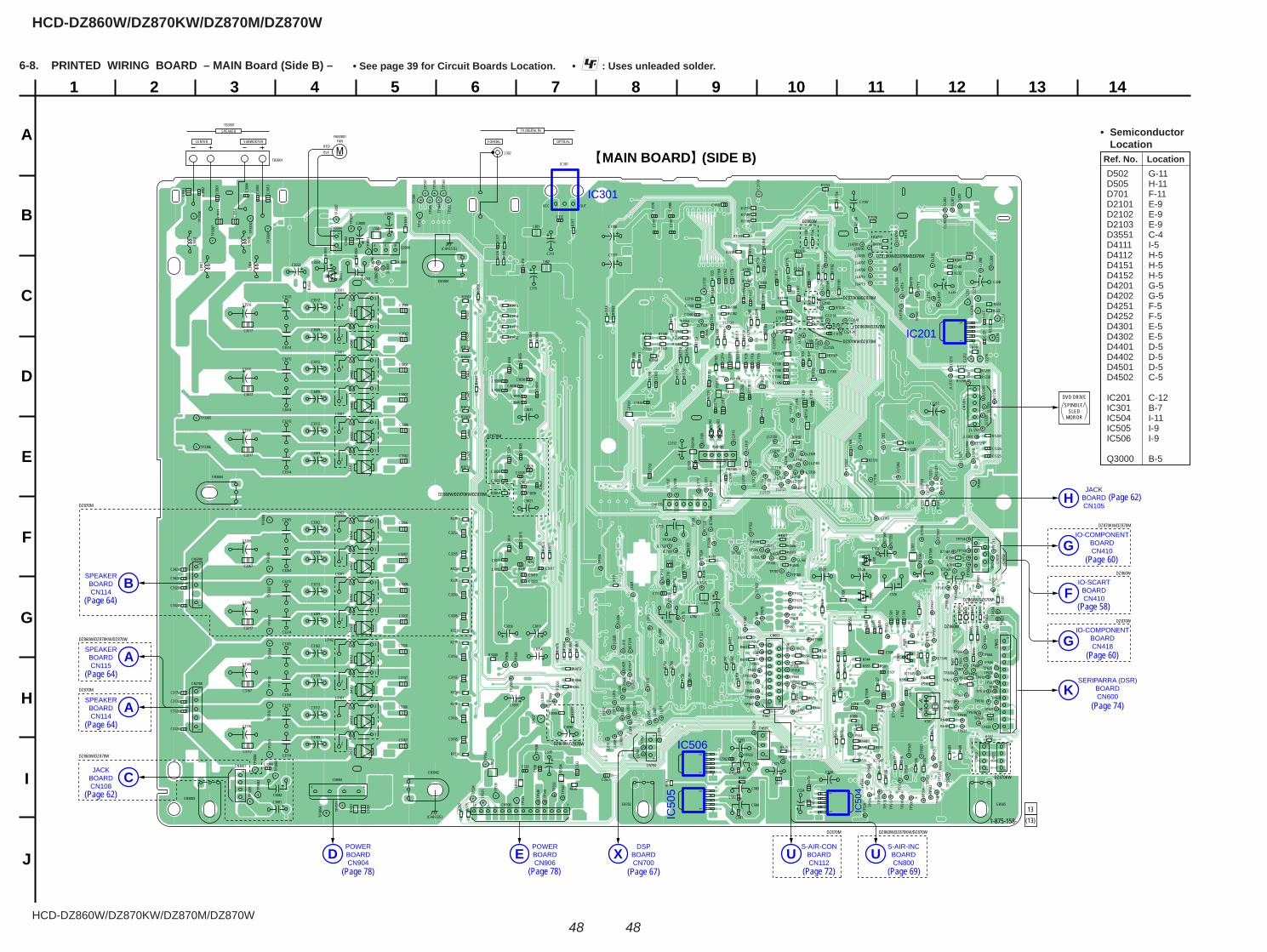
HCD-DZ860W/DZ870KW/DZ870M/DZ870W
HCD-DZ860W/DZ870KW/DZ870M/DZ870W
4848
1
A
B
C
D
E
F
G
H
I
J
2 3 4 5 6 7 8 9 10 11 12 13 14
+
+
+
+
+
+
+
+ +
+
+
+
+
++
++
++
+
+
+
+
+
+
+
+
++
++
++
++
++
+
++
+
+
+
+
+
++
++
+
+
+
+
+
+
+
+
+
+
+
+
M MAIN BOARD (SIDE B)
DVD DRIVESPINDLE/
SLEDMOROR
13(13)1-875-158-
DZ870KW/DZ870M/DZ870W
DZ860W/DZ870W
DZ870KW/DZ870M
DZ860W/DZ870M
DZ870KW/DZ870M
DZ860W
DZ870W
DZ870M DZ860W/DZ870KW/DZ870W
DZ860W
DZ870KW
DZ860W/DZ870W
DZ860W/DZ870W
DZ870KW/DZ870M
DZ860W
DZ860W/DZ870KW/DZ870W
DZ860W/DZ870KW/DZ870W
DZ870M
DZ870M
DZ870M
SPEAKERBOARDCN114
B
SPEAKERBOARDCN114
A
SPEAKERBOARDCN115
A
JACKBOARDCN108
C
POWERBOARDCN904
DPOWERBOARDCN906
EDSP
BOARDCN700
XS-AIR-CON
BOARDCN112
US-AIR-INC
BOARDCN800
U
JACKBOARDCN105
H
IO-COMPONENTBOARDCN410G
SERIPARRA (DSR)BOARDCN600K
IO-SCARTBOARDCN410F
IO-COMPONENTBOARDCN418G
IC506
IC50
5
IC50
4
IC201
IC301
15
151
51
5
ICT560
ICT561
C3253
C3255
C3256
JL30
96
C3257
R601
ICT5
69
C112
5
R602
C112
6
R603
C112
7
R604
R3040
R605
R110
1
C112
9
R606
R1102
R607
R110
3
R220
CL21
20
R608
CN51
3CN
625
CN51
2
14
14
131
16
11
22
TP31
01
R110
5
JL21
01
R221
CL2121
R609
TP31
02
R110
6
JL2102
R222
CL21
22
TP31
03
ICT5
73
JL2103
R223
CL21
23
TP31
04
C1130
JL2104
CL2124
C3071
JL2105
CL2125
JL2106
CL21
26
C3267
JL2107
R610
JL2108
R611
JL2109
R612
TP33
01
R305
1
TP33
02TP
3303
TP33
04
ICT5
80
JL21
10
TP3305
ICT581
JL2111TP3306
ICT5
82
JL21
12
R232
C238
C239
R3056
TP33
07
JL21
13
TP33
08
C1140
JL2114R3
058
R305
9
TP33
09
JL21
15
CL21
35
JL21
16
ICT5
87JL
2117
CL21
37
C114
4
JL2118
CL2138
ICT588
R621
CN507
CN651
ICT5
89
JL2119
CL21
39
C1146
R3253
R306
0
TP33
10
C1149
R306
3
R627
R306
4
JL2120
CL2140
R628
R3065
JL2121
CL2141
R3066
R1126
JL2122
JL2123
JL21
24
R306
9
C115
1
C3094
C1154
C115
5
C1156
R307
0
C1158
JL001
R307
1
C115
9
JL00
2
R636
114
R3266
R3072
R113
2
JL00
3
R307
3
R113
3
CL100
JL00
4
R113
4
R638
JL00
5
JL00
6
JL00
7
R1137
JL00
8
R113
8
C1160
C210
0
JL00
9
C116
1
C210
2
C116
2
C116
3
R640X501C1
164
R641
C1165
R642
JL01
0
R644R1
140
C2108
R645
C116
9R1
141
C221
JL01
1
JL01
2
C222
JL01
3
JL01
5
R1145
JL01
6
R1147
JL01
8
R1148 C1170
TP50
1
JL01
9
C1171
CN2101C2112
TP50
2
C117
2
TP50
3
C117
4
C211
4
R650
TP50
4
TP50
5
C117
5
C211
5
R651
TP50
6
C117
6
C211
6
TP50
7
C211
7
TP50
8
JL02
0
C211
8
R654
TP50
9
JL02
1
R655
C117
9
C2119
C1177
C315
C313
C1190
R656
R1152
C250
2
JL02
3
R115
3
C250
3
JL02
4
R173
0
R1154
TP70
1
R309
5
R115
5
TP70
2
JL02
6
R3096
TP703
JL02
7
TP704
TP51
0
C118
0
JL02
8
TP705
C118
1
JL02
9
TP706
TP51
2
TP707
TP51
3
TP708C527 C528
C526
C717C706
TP51
4
R661
TP70
9
TP51
5
D210
1
TP51
6
D210
2
R662
TP51
7
D210
3
TP51
8
C240
TP51
9
R666
R2103
R667
TP71
0
R210
4
TP71
1
TP712
R1743
TP71
3
TP52
0
R210
8
TP714
TP52
1
C119
1
TP522 TP523
R1749
CN1105
C775
C720
61
TP52
7
C1197
C119
9
R117
1
R1750
R117
5
R1751
R117
6
R1753
R2117
R175
4
TP53
1
R2119
D425
1D4
252
TP53
3
TP53
4
TP729
TP53
5
TP53
6
TP53
7
R683
TP53
8
TP53
9
13
CN704
13
R118
1
R118
2
R689
CL12
02
CL12
03
TP54
0
R2129
TP54
1
TP54
2
TP54
3
TP54
4
R690
TP54
5
CL12
09
TP547
R213
4
CL12
10CL
1211
CL12
12
R213
7
TP55
0
R119
8
R2138
TP55
1
L301
L302
TP55
2
C3103
TP553
TP55
4
C3105
C3106
C3107
JL1201
R1781
JL12
02
R1782
C330
3
JL12
03
CN12
01JL
1204
C330
5
JL12
05
C3306
JL12
06
C3307
JL12
07
TP56
3
JL12
08
TP56
4
JL1209
C3117
CN3001
R2150
L701
R2151
L702
R215
2
L703
C350
3
JL12
10
C350
5
JL1211
R215
5
C3506
JL12
12
R215
6
C3507
JL12
13
R215
7R2
158
R215
9
C3122
C3317
C3123
R2160
R3103
C3322
C3517
C3323
C390
1
TP58
1
C390
2
TP58
2
C390
3 TP58
3
C390
4
TP58
4TP
585
TP58
6
R3303
TP58
7
TP58
8
L3501
3
1
4
2
L3401
3
1
4
2
L3301
3
1
4
2
L3202
3
1
2
L3201
3
1
2
L31023
1
2
L3101
3
1
2
R3116
R2178
C1187
C391
1
R217
9
C391
2
R3503
C391
3
L3000
Q3000BCE
C391
4
R2180
R218
1
R3316
R2182
R218
4
FB50
5
R218
5
FB50
6
R2188
R218
9
JL4701
JL47
02
C3153
JL4703
JL4511
C3155
JL4705
R3516
C3156
JL47
06
C3157
JL4707
R501
JL4709
R502
EB505EB702
EB3002
(CHASSIS)
(CHASSIS)
EB3001
EB3004
C3005
C3001
C3551C3552
CENTER SUBWOOFER COAXIAL OPTICAL
TV DIGITAL IN
J302
IC301
SPEAKER
C3512
C3509
C3412
C3409
C3312
C3309
C3262
C3259
C3212
C3209
C3162
C3159
C3112
C3109
CN904
1 4
C3114
C3164
C3165
C3214
C3215
C3264
C3265
C3314
C3315
C3414
C3415
C3514
C3515
C3115
C3081
C3082
C3000CN3000
TB3901
FAN3001FAN
REDBLK
TB3901
12
EB3003
R390
7
TP30
00
R508
TP30
01
JL4711
TP30
03
FB1107
R317
JL4713
TP30
04
C1225
FB1109
R319
JL47
15
C1226
JL47
16
TP30
07
C3167
JL47
17
JL47
18
R3911
JL47
19
R3912
R3913
R3914
R1205
FB11
11
FB11
12
R517
FB11
13
R518
FB11
15
C3172
FB11
16
C3173
FB1117
FB1118
R328
R329
R711
C530
C524
C573
R716
R523
R3153
R1213
R525
R526
R527 R528
R530
R531
R726
L390
2
L390
3
R533
R534
R535
D355
1
R3166
R539
R355
1
D430
1D4
302
R355
3
C501
D411
1
C502
L305
2
D411
2
C503
C504
R540
C505
R735
R123
2
C312
VCC OUT
C507
R544
C508
R123
4
C314
R545
D450
1
CL20
1
R1236
C1217
D450
2
CL20
2
R1237
CL20
3
C317
R1238R1239
CL20
6
R4503
CL20
7
R4504
CL20
8
R4505
CL20
9
R4506
R4507R4508
R550
C515
R551
C517
R553
R1243
C518
CL21
0
R555
CL21
1
R556
CL21
2
R557
CL21
3
C710
R558
CL21
4
C711
C709
R559
CL21
5
TP60
1CL
216
TP60
2
TP603
TP30
53
CL21
7
TP604
TP30
54
TP60
5
C705
TP606
C716
TP607R753 TP608
R560
TP609
C525
R756
R563
R758
R991
8
C529
FB2101
JL70
1
JL70
2
FB2103
JL70
3
TP610
FB21
04
JL30
01
TP611
FB2105
JL30
02
TP612
C722
R4716
JL30
03 TP613
R4717
JL30
04
TP614
R471
8
TP61
5
R471
9
TP616
C532
R992
2
TP617
C533
CN506
TP618TP619
R2201
R220
3
C538
R576
R577
TP620
R578
R579
TP62
3TP62
4
TP625
D415
1
TP626
D415
2
TP627
R580
TP628
R581
CN70
1CN
702
TP629
R582
R585
R586 TP630
TP30
81
14
CN3100
15
CN3200
15
TP631
TP30
82
TP632
TP30
83
TP633
R780
TP30
84
R781
TP63
5
CL11
06
TP63
6
CL11
07
TP63
7
R591
CL1109
R592
R787
R593R595
C751
C300
2
D502
R794
117
216
D505
R797
TP651
D701
TP652
C3203
TP65
3
CL1123
TP65
4
C3205
TP655
CL17
01
C3206
C3012
TP656
C572
C3207
C3013
ICT5
17
TP657JL
1107
C301
4
JL11
08TP658
C301
5
ICT5
19
JL11
09
TP659
C3016
C3017C3018C3019
C340
3
TP660
JL11
10
C340
5
ICT5
21JL
1111
TP661
C3406
JL11
12
TP662
C3407
ICT523
TP663
C3020
ICT5
24
TP664
TP665
C581
C584
C3022
C582
C583
C594
C593
C3217
C3023
ICT527
TP667
C302
4
ICT5
28
C302
5
ICT5
29
C3026
C302
7
C3028
C3029
R300
2
R300
3
R3004
ICT5
32
TP672
C3417
C3416
C3516
C3316
C3266
C3216
C3166
C3116
TP67
3
ICT5
33
C3030
TP674
D420
1
C591
D420
2
C3032
TP676
C592
C3033
C303
4
ICT5
38
TP678
C303
5
TP67
9
C3036
R3203
C303
7
C3038
C3039
C3422
C3423
TP680
ICT5
41
TP68
1
ICT5
43
C3040
C3031
C3021
C3011C3056
C3054
C3091
C3090
C539
ICT5
44
ICT545
ICT546CL
682
C1102
R3403
ICT547
C110
6
C1108
C110
9
R3216
R203
CL21
04
C305
1
ICT5
55 ICT5
56
ICT5
57
C111
4
R208
C111
5
TP69
9
R3416
C111
6
L390
1
L390
4
D440
1D4
402
6-8. PRINTED WIRING BOARD – MAIN Board (Side B) – • : Uses unleaded solder.• See page 39 for Circuit Boards Location.
Ref. No. Location
• Semiconductor Location
D502 G-11 D505 H-11 D701 F-11 D2101 E-9 D2102 E-9 D2103 E-9 D3551 C-4 D4111 I-5 D4112 H-5 D4151 H-5 D4152 H-5 D4201 G-5 D4202 G-5 D4251 F-5 D4252 F-5 D4301 E-5 D4302 E-5 D4401 D-5 D4402 D-5 D4501 D-5 D4502 C-5
IC201 C-12 IC301 B-7 IC504 I-11 IC505 I-9 IC506 I-9
Q3000 B-5
(Page 78) (Page 78)
(Page 64)
(Page 64)
(Page 62)
(Page 62)
(Page 60)
(Page 58)
(Page 72)
(Page 64)
(Page 67) (Page 69)
(Page 74)
(Page 60)
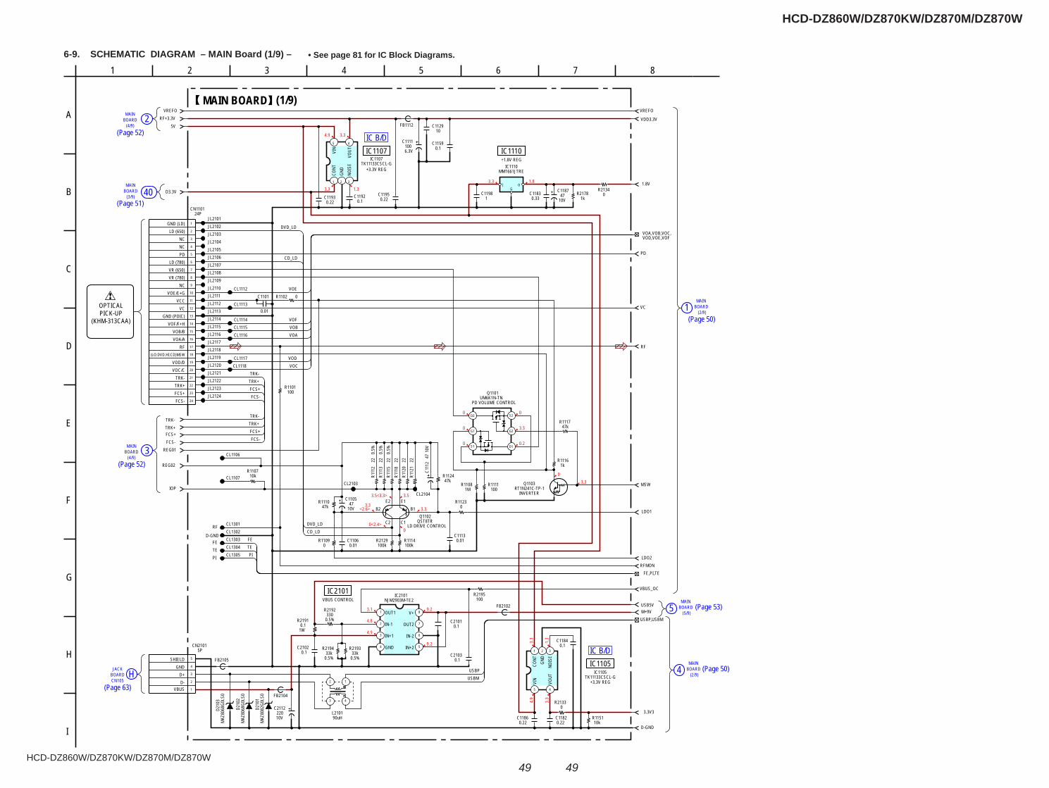
HCD-DZ860W/DZ870KW/DZ870M/DZ870W
HCD-DZ860W/DZ870KW/DZ870M/DZ870W
4949
6-9. SCHEMATIC DIAGRAM – MAIN Board (1/9) – • See page 81 for IC Block Diagrams.
(5/9)
MAINBOARD5
(2/9)
MAINBOARD4
(2/9)
MAINBOARD1
MAIN
(3/9)BOARD
MAIN 2(4/9)
BOARD
40
MAIN 3(4/9)
BOARD
JACKH
CN105BOARD
IC B/D
IC B/D
1.83.3
4.9 3.3
3.3 1.3
0
3.3
0.2
0
0
0
03.3
3.5
3.3
00<2.4>
<2.6>3.3
3.5<3.3>
3.1
4.8
4.9
9.2
9.2 3.3
1.3
4.9
3.3
47kR1124
0.1C1192
5 4
321
TK11133CSCL-GIC1105
CONT
GND
NOIS
EVO
UT
VIN
0.5%
22R1
112
100kR1114
0R1109 0.01
C1113
0.5%
22R1
115
100R1101
10kR1107
10V47
C1105
0.22C1195
47kR1117
0.22C1182
1kR1116
0.01
C1101
0.1C1184
10V
47C1
112
1MR1108
1
2
3
4
5
6
7
8
9
10
11
12
13
14
15
16
17
18
19
20
21
22
23
24
CN110124P
GND (LD)LD (650)
NCNCPD
LD (780)VR (650)VR (780)
NCVOE/E+G
VCCVC
GND (PDIC)VOF/F+H
VOB/BVOA/A
RF(LO:DVD.HI:CD)MSW
VOD/DVOC/C
TRK-TRK+FCS+FCS-
0.01C1106
0.5%
22R1
113
5 4
321
TK11133CSCL-GIC1107
CONT
GND
NOIS
EVO
UTVIN
0R1123
47kR1110
0.22C1193
22R1
118
RT1N241C-TP-1Q1103
INVERTER
22R1
120
100kR2129
100R1111
D1
G2
S2D2
G1
S1
UM6K1N-TNQ1101
PD VOLUME CONTROL
Q1102QST8TR
LD DRIVE CONTROL
JL2101JL2102
JL2105JL2106JL2107JL2108
JL2110JL2111JL2112JL2113JL2114JL2115JL2116JL2117JL2118JL2119JL2120JL2121JL2122JL2123JL2124
CL1106
CL1107
0R2133
REG01
TRK-TRK+FCS+FCS-
REG02
IOP
VREFORF+3.3V
5V
D3.3VI O
G
MM1661JTREIC1110
1C1198
0.33C1183
1kR2178
0.22C1186
10kR1151
FB1112
0R2134
CL1112
CL1113
CL1114CL1115CL1116
CL1117CL1118
CL2103
CL2104
JL2103JL2104
JL2109
6.3V100
C1111
10C1129
0.1C1159
0.1C2102
FB2104
FB2105
12
3 4
90uHL2101
1
2
3
4
5
5PCN2101
VBUSD-D+
GNDSHIELD
CL1301RFCL1302
D-GNDCL1303FECL1304TECL1305PI
USB5V
0.1C21010.5%
330R2192
0.5%33k
R2194
0.5%33k
R2193
1W0.1
R2191
0.1C2103
100R2195
8
7
6
54
3
2
1
NJM2903M-TE2IC2101
OUT1
IN-1
IN+1
GND IN+2
IN-2
OUT2
V+ M+9VFB2102
10V
C2112220
10V47
C1187
R1102 0
MAZ
8068
G0LS
0D2
103
MAZ
8068
G0LS
0D2
102
MAZ
8082
G0LS
0D2
101
FE,PI,TE
USBP,USBM
1.8V
VREFO
VDD3.3V
PD
VC
RF
MSW
LDO1
LDO2RFMON
VBUS_OC
3.3V3
D-GND
22R1
121
TRK+FCS+FCS-
FCS+
TRK-
FCS-
TRK+TRK-
DVD_LD
CD_LD
FETEPI
VOE
VOFVOBVOA
VODVOC
USBPUSBM
CD_LDDVD_LD
(1/9)MAIN BOARD
+1.8V REGIC1110
+3.3V REG
IC1107
VBUS CONTROLIC2101
+3.3V REG
IC1105
E2 E1B2 B1
C2 C1
VOA,VOB,VOC,VOD,VOE,VOF
OPTICALPICK-UP
(KHM-313CAA)
82
E
A
6
F
7
B
C
D
H
1 54
I
G
3
(Page 52)
(Page 51)
(Page 52)
(Page 63)
(Page 50)
(Page 53)
(Page 50)
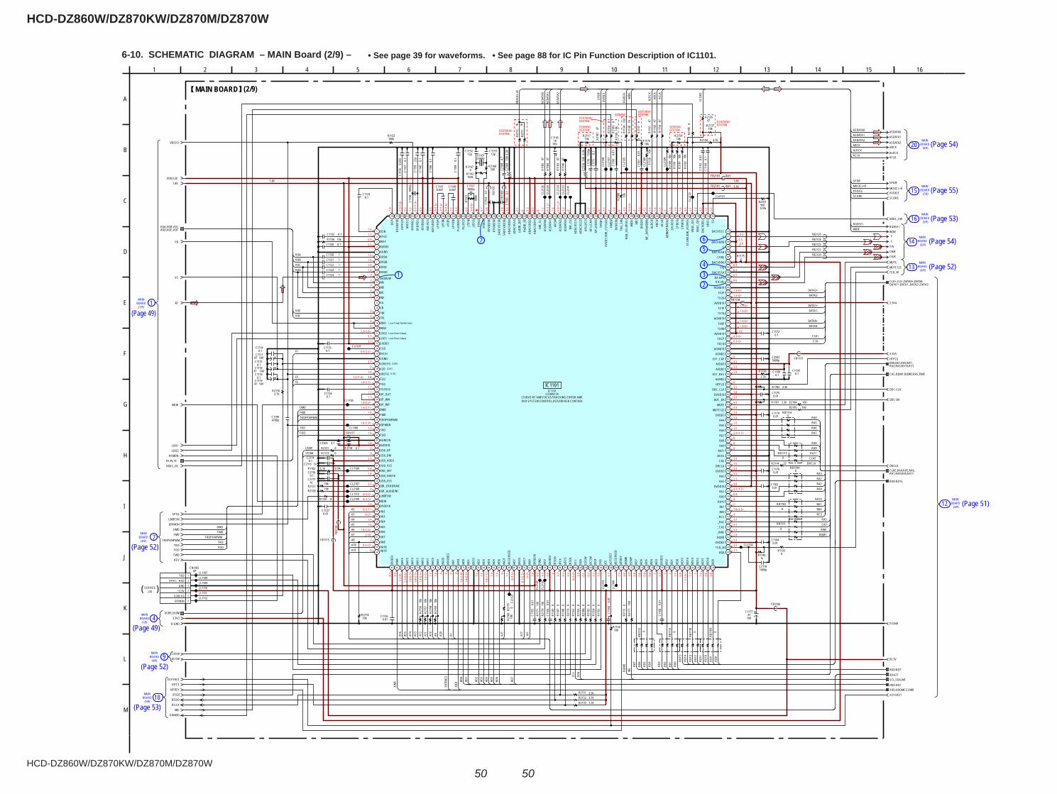
HCD-DZ860W/DZ870KW/DZ870M/DZ870W
HCD-DZ860W/DZ870KW/DZ870M/DZ870W
5050
6-10. SCHEMATIC DIAGRAM – MAIN Board (2/9) – • See page 39 for waveforms. • See page 88 for IC Pin Function Description of IC1101.
(5/9)
MAINBOARD16
234
567
1
BOARDMAIN
(6/9)20
BOARD15(7/9)
MAIN
BOARD14(6/9)
MAIN
BOARD13(4/9)
MAIN
BOARD(3/9)
MAIN
12
MAINBOARD
(5/9)10
9MAIN
BOARD(4/9)
BOARD 4(1/9)
MAIN
BOARDMAIN
(4/9)7
MAIN
(1/9)BOARD 1
1.9<
0.9>
1.51.20.93.3
1.61.61.61.6
22222
2200
3.3<2.6>3.33.3
0.5<2.2>
2.72
1.41.2<1.4>
1.4<1.2>1.21.71.7
1.4<0.2>1.4<2.1>
1.40
1.6<1.4>1.31.4
1.800
3.3
0.81.8
3.30
0<3.3>0<3.3>
1.80<2.1>
0<2>1.91.6
1.8<2.4>2<0>
20.5<3>
0
3.3
3.3
1.2<
0>2.
1<0.
6>
1.4<
0.5>
1.4<
0.5>
1.2<
2> 1.4
1.8 0 0 2 0
1.6<
1.4>
1.4<
0.6> 1.5
1.5
1.9<
1.5> 1.9
1.9 0
1.1
2<1.
5>
0.1<
2.3>
0<2> 1.8
3.3
3.3
3.3 0
3.3
3.3
3.3
0<3.
3> 3.3
0.3
0.3
3.3
3.3
3.3
2.5
2.4
3.3
0.8
0.8
0.9
0.9 1
3.3 1 1
1.1
0.9
1.1<
1.6> 1.
2 11.
10.
80.
8
1.13.33.32.43.33.13.231.9<1.5>200.42.1<1.7>1.82.11.33.31.53.3
0002.2<1.7>1.51.51.83.33.33.33.21.83.20
1.33.33.30
0.3<0>0.3<0>
1.81.3<0>1.3<0>
1.3<0>1.3<0>
1.3<0>1.3<0>
0.60.70.40.3
0.63.30.4
1.4
1.3<
1.8>
3.3
1.3
0.1<
1.4>
3.3
3.3
0<1.
5>2<
1.6>
0<1.
6>1.
73.
3
0.9
1<0.
6>
0.7
1.8
1.8
3.3
0.1
0 3.3
3.3
0 1.2
0<1.
2>1.
60.
6<1.
2>1.
20 1.
73.
30 3.
30 1.
80 3.
30<
3.3>
0 3.3
1.2
1.6
1.6
1.2
0 1.6
1.6
1.6
3.3
3.1
3.3
3.3
1.2
1.2
DZ870KW/DZ870M
DZ860W/DZ870W
DZ870KW/DZ870M
DZ860WDZ870KW/DZ870M
DZ860W/DZ870W
DZ870KW/DZ870W
CL1108
0.1
C114
9
0.1C1133
47R1
185
0.01C1162
47R1
161
3.3kR2151
100R1156
0.01
C115
6
4700pC1199
2.7kR2110
0RB
1113
0.1C1116
0.1
C113
7
0.01C1164
1C1120
0.01C1175
0.03
3C1
135
0R1
152
1C1122
0.01C1136
0.1C1126
47R1
184
0.01
C116
1
1C1124
3.3kR2150
0.047C1148
0.1C1115
0.1C1130
0.01
C115
5
47R1
159
0.1
C114
0
27MHzX1101
47R1
160
0.1C1125
3.3kR21520.
01C1
163
47R1
183
0.1C1132
0R1
155
22p
C113
9
0.01
C115
8
0RB
1112
0.01C1174
100kR1132
0.01C1127
0.1
C114
6
0.01
C116
0
0.01C1176
1C1123
0.047C1147
15kR1136
R211
50
C116
90.
1
R210
30
1C1121
JL11
60
JL1107JL1108JL1109JL1110JL1111JL1112
CL1105
CL1101
REV
TRO
FWDFOO
IOPMON
SPFG
TSD_M
DMOFMO
TROPENPWM
0R2
176 CL
1121
CL21
01
CL21
02
0R1
145
0R1
147
0R1
148
0R2
119
0R1
153
0R1
154
CL11
23
LIMITSW
0R1139
22R2114
0RB
1110
0RB1104
0RB1111
0RB
1109
0RB1103
0RB1115
0RB1114
R113
70
R117610k
0R1133
R113
81k
0R1175
FB2121FB2120
FB2124FB2122
MUTEMUTE123
R218
747
0.1
C117
1
100kR1142
0R2167
12pC1152
12pC1153
1000pC1151
680k
R114
1 FB11
07
16V10
C1145
0uHFB2101
4.7
C210
86.
3V10
0C2
109
0uHFB2103
FB1106
1000
pC1
138
330R2168
6.3V
100
C211
0 R112
610
k
0.1C1114
CL2120
0.1
C115
4
CL21
39
CL21
40
CL21
41
0.1
C116
5FB11
09
3.3kR1782
CL1109
100
R117
110
0R2
179
100
R217
7
0.5%5.1kR1103
CL21
38
CL21
37
CL21
35
R118
210
k
R218
910
kR1
181
10k
R218
110
k
100R2184100R2185
10k
R218
0
OCSWCKSW
R113
410
0
R211
11k
4.7kR2104
CL1110
CL2107CL2108
CL2109
R215410k
SCORE
R213547
10V47C1117
10V47C1118
10V47C1119
5600pC2502
0.1C1108 0.1
C1109
FB1115
FB11
16
10C21150.1
C2114
0.1C2116
10C2117
FB1117
0.1C21184.7C2503
FB1118
0.1C1172
1000pC2119
CL2121
CL21
22CL21
23CL
2124
CL21
25CL
2126
R210
80
1500
pC1
170
10kR2155
10k
R215
610
kR2
157
10k
R215
810
kR2
159
2.7k
R1730
0.5%560
R2101
XVOICE
R211710k
R211
60
0R21210R2123
1kR1140
XSYSRSTXIFCS
XIFBSYIFSDI
MIC
0.01
C114
4
1
2
3
4
5
6
6PCN1105
TXDRXDGND
+3.3VV2REFORFMON
47R1
146
3.3kR1781
R218
80
R218
20
R212710k
R2128 10k
1
2
3
4
5
6
7
8
9
10
11
12
13
14
15
16
17
18
19
20
21
22
23
24
25
26
27
28
29
30
31
32
33
34
35
36
37
38
39
40
41
42
43
44
45
46
47
48
49
50
51
52
53
54
55
56
57
58
59
60
61
62
63
64
65 66 67 68 69 70 71 72 73 74 75 76 77 78 79 80 81 82 83 84 85 86 87 88 89 90 91 92 93 94 95 96 97 98 99 100 101 102 103 104 105 106 107 108 109 110 111 112 113 114 115 116 117 118 119 120 121 122 123 124 125 126 127 128
129
130
131
132
133
134
135
136
137
138
139
140
141
142
143
144
145
146
147
148
149
150
151
152
153
154
155
156
157
158
159
160
161
162
163
164
165
166
167
168
169
170
171
172
173
174
175
176
177
178
179
180
181
182
183
184
185
186
187
188
189
190
191
192
193194195196197198199200201202203204205206207208209210211212213214215216217218219220221222223224225226227228229230240 231232233234235236237238239241242243244255256 245246247248249250251252253254
IC1101CXD9917R
OSNRFGCIREFAVDD3AGNDDVDADVDBDVDCDVDD
DVDRFIPMAMBMCMDSASBTNITPIMDI1MDI2LDO2LDO1SVDD3CSORFLVLSGNDV2REFOV2OVREFOFEOTEOTEZISLVOP_OUTOP_INNOP_INPDMOFMOTROPENPWMIOPMONTROFOOAGND18AVDD18USB_DPUSB_DMUSB_VDD3USB_VSSPAD_VRTUSB_VDD18USB_VSSDIR_ERROR/NCDIR_AUDIO/NCLIMITSWMSWDVDD18HA2HA3HA4
HA5HA6HA7HA8HA18HA19
DVDD
3XW
RHA
16HA
15HA
14HA
13HA
12HA
11HA
10HA
9HA
20XR
OMCS
HA1
XRD
HD0
HD1
DVSS
HD2
HD3
HD4
HD5
HD6
HA21
RESE
RVED
HD7
DVSS
HA17
HA0
DVDD
18FW
DRE
VDV
DD3
IFSD
OIF
CKxIF
CSIF
SDI
SCL
SDA
CKSW
OCSW
RXD
TXD
ICE
xSYS
RST
RESE
RVED
xIFBS
YDQ
M0
EEW
PRD
7RD
6RD
5RD
4RD
3DV
DD3
RD2
RD1
RD0
RD15
RD14
RD13
RD12
RD11
RD10
RD9
FSVR
EFDA
CVDD
CVB
US_O
EVB
US_O
CSC
ORE/
DIR_
XSTA
TESP
MCK
SPBC
KSP
LRCK
ADIN
(SPD
ATA)
ACLK
ABCK
ALRC
KM
C_DA
TA(A
DIN)
DVDD
3M
ICW
IDE
RGB_
SEL/
DSEL
TRG_
SWDV
DD18
KMOD
XVOI
CE/D
IR_C
SFLA
GSP
DIF
APLL
VDD3
APLL
CAP
APLL
VSS
ADAC
VSS2
ADAC
VSS1
DIR_
CEAS
DATA
3AS
DATA
2AV
CMAS
DATA
1AS
DATA
0DI
R_CL
ADAC
VDD1
ADAC
VDD2
Rt/D
IR_D
ILt
/DIR
_DO
ADAC
VSS3
ADAC
VDD3
SADC
VDD1
8SA
DCVS
S18
RFGN
D18
RFVD
D18
XTAL
OXT
ALI
JITFO
JITFN
PLLV
SSPL
LVDD
3LP
FON
LPFI
PLP
FIN
LPFO
PAD
CVDD
3AD
CVSS
RFVD
D3RF
RPDC
RFRP
ACHR
FZC
CRTP
LPRF
GND1
8OS
P
RGBSELWIDE
SPDIF
ASDATA0ASDATA1
ASDATA2
MUSICL+R
C
CB/BCR/R
Y/G
IFSCK
KRMOD
IFSDO
VBUS_SW
FB2125 Y
10V47
C1177
FB1113
R213710k
R213
810
k
R216
010
kUSBP,USBM
FE,PI,TE
D-GND
3.3V3
VBUS_OC
RFMONLDO2LDO1
MSW
RF
VC
PD
VDD3.3V
VREFO
1.8V
XRD,XROMCS,XWR
SCL,SDA,WE
CAS,DQM1,DQMO,RAS,RWE
XSYSRST
D3.3V
D-GND
DRCLK
DDC-DA
DDC-CLK
3.3V4
3.3V5HTPLG
ABCK
ALRCKACLK
R211
21k
A0A20
A13
A14
A15
A16
XWR HD
2HD
3HD
4
HD6
RD6
RD5
RD4
RD3
RD2
RD1
RD0
A19A18
A2A3A4A5A6A7
XROM
CSA1
XRD HD
0HD
1
HD5
HD7
A17
DQM
O RD7
RA4RA5RA6RA7
RA8RA9
RA11CLKE
DRCLK
RA3RA2RA1RA0
RA10BA1BA0RCS
RASCAS
RWEDQM1
RD8
RD9
RD10
RD11
RD12
RD13
RD14
RD15
VODVOCVOBVOA
VOEVOF
PI
FETE
DMOFMOTROPENPWM
TROFOO
USBPUSBM
DMOFMO
TROPENPWMTROFOO
A12
A11
A10
A9 A21
SDA W
E
SCL
DATA2+DATA2-
DATA1-
CLK+
DATA1+
DATA0+DATA0-
CLK-
1.8V1.8V
3.3V
A8
WIDERGBSEL
RGBS
ELW
IDE
ASDATA2ASDATA1ASDATA0
ASDA
TA0
ASDA
TA1
ASDA
TA2
ACLK
SPDI
F
ALRC
KAB
CKAC
LK
MUS
ICL+
R
MUSICL+R
SCOR
E
XVOICESCORE
XVOI
CE
SPDIF
ABCKALRCK
[DRIVE]
[2.0V]
[2.8V]
Laser Driver Output
[1.4V]
Laser Driver Output
Laser Power Monitor Input
(2/9)MAIN BOARD
CD/DVD RF AMP,FOCUS/TRACKING ERROR AMP,
IC11011.4
DVD SYSTEM CONTROL,DSP,DIR/USB CONTROL
CLK+,CLK-,DATA0+,DATA0-,DATA1+,DATA1-,DATA2+,DATA2-
VOA,VOB,VOC,VOD,VOE,VOF
BA0,BA1,RA0,RA1,RA2,RA3,RA10,RCS
CLKE,RA4,RA5,RA6,RA7,RA8,RA9,RA11
RD0-RD7
SERVICEJIG( )
H
5 13
G
6
M
C
1641
D
7
L
A
2 159
F
11
K
I
10 143
B
12
E
J
8
A0-A21
HD0-HD7
RD8-RD15
RD8TSD_MDVDD3DQM1_RWE_CAS_RAS_RCS
BA0BA1
RA10RA0RA1
DVDD18RA2RA3
DVDD3DRCLK
CKEDVSSRA11RA9RA8RA7RA6RA5RA4
DVDD3MUTE123
MUTEDDC_DADVDD18
DDC_CLKHTPLGAGND3
EXT_RESAVDD3AVDD3
EXT_CAPAGND3
AGND18TXCNTXCP
AVDD18TX0NTX0P
AGND18TX1NTX1P
AVDD18TX2NTX2P
AGND18
R/Cr/PrB/Cb/Pb
DACVSSAY/G
DACVDDACVBS
DACVSSBC
DACVDDBY
DACVSSC
(Page 49)
(Page 52)
(Page 49)
(Page 52)
(Page 53)
(Page 54)
(Page 55)
(Page 53)
(Page 54)
(Page 52)
(Page 51)
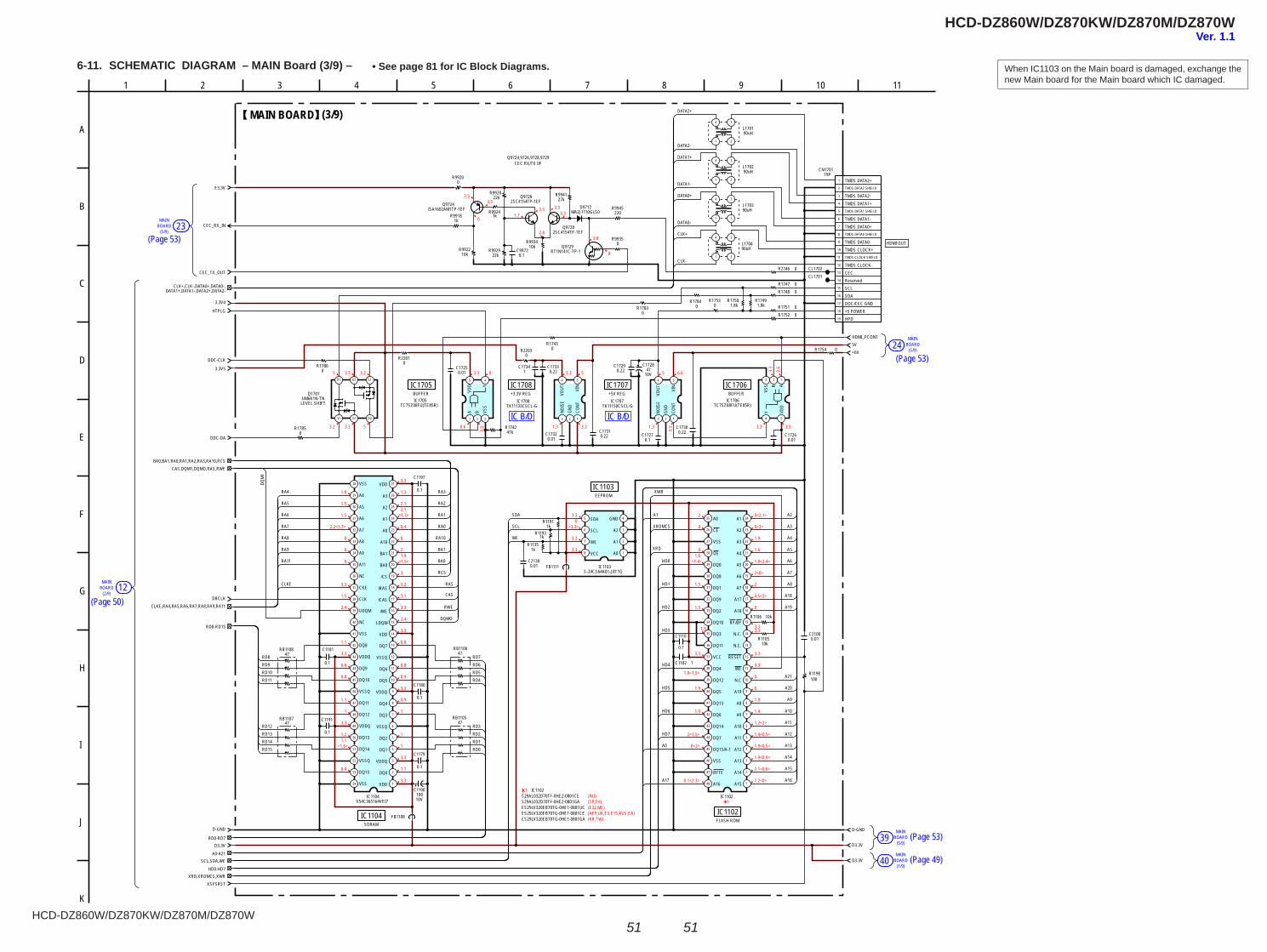
HCD-DZ860W/DZ870KW/DZ870M/DZ870W
HCD-DZ860W/DZ870KW/DZ870M/DZ870W
5151
6-11. SCHEMATIC DIAGRAM – MAIN Board (3/9) – • See page 81 for IC Block Diagrams. When IC1103 on the Main board is damaged, exchange the new Main board for the Main board which IC damaged.
BOARDMAIN
(5/9)23
BOARDMAIN
(2/9)12
MAIN
24(5/9)
BOARD
39(5/9)
MAINBOARD
40(1/9)
MAINBOARD
IC B/D IC B/D
3.3
1.7
2.8
0
3.8
3.33.33.5
3.5
0
5 3.3 3.2
3.2 3.3 5 0.6
03.3
3.3
5 6.6
1.3
3.3
1.8
1.5
1.5
2.2<1.7>
0
0
0
3.3
1.5
2.4
1.1
3.3
0.8
0.8
1.1
1
3.3
1.21.1
<1.6>
0.9
3.3
1.3
2.12.1
<1.7>
0.4
0
21.9
<1.5>
3
3.2
3.1
3.3
2.4
3.3
0.8
0.8
0.9
3.3
0.9
1
1
1
3.3
1.1
3.3
3.30
<3.3>
3.3
3.3
2
0
01.6
<1.4>
1.5
1.5
1.5
3.3
1.9<1.5>
1.9
1.9
2<1.5>
0<2>
0.1<2.3>
0<2.1>
0<2>
1.9
1.6
1.8<2.4>
2<0>
2
0.5<3>
0
3.33.3
3.3
3.3
0
0
1.8
1.4
1.2<2>
1.4<0.5>
1.9<0.5>
1.9<0.9>
2.1<0.6>
1.2<0>
3.3 5
3.31.3 3.3 3.3
3.3
0.6
1(RU)(SP,TH) 1(E32,MX)(AEP,UK,E3,E15,AUS,EA)(KR,TW)
0.1
47RB1106
1C1102
0.1
C1179
10kR1105
1kR1193
47RB1105
10kR1106
1kR1191
0.1
C1191
0.1
C1197
0.1
C1180
D-GND
D3.3V
FB1108
0.1
C1181
1kR1135
0.01C2130
FB1111
C1110
0.1
47RB1107
47RB1108
D1 G2 S2
D2G1S1
UM6K1N-TNQ1701
LEVEL SHIFT
54
3 2 1
TK11150CSCL-GIC1707
CONT
GND
NOIS
EVO
UT VIN
5 4
321
TC7SZ08FU(TE85R)IC1705
A B VSS
Y
VDD
0R1786
0R1785
0R1784
0R1783
0R17470R1748
0R17511.8kR1750
0R1752
CL1701
0.01C1725
C1727
0R1753
0.22C1730
0.22C1729
10V47
C1728
CL17020R2746
220R9945
0R9935
RT1N141C-TP-1Q9729
2SC4154TP-1EFQ9728
2SC4154TP-1EFQ9726 27k
R994122kR9928
1kR9924
10kR9934
22kR9929
10kR9922
R99200
1kR9918
0.1C9972
48
43 6
5
46
4
3
2
1
47
45
44
42
41
37
38
39
40
12
10
11
9
8
7
36
31
32
33
34
35
18
17
16
15
14
13
30
29
28
27
26
25 24
23
22
21
20
19
IC1102
A15
A14
A13
A12
A11
A10
A9
A8
A19
N.C
WE
RESET
N.C.
N.C.
RY/BY
A18
A17
A7
A6
A5
A4
A3
A2
A1A0
CE
VSS
OE
DQ0
DQ8
DQ1
DQ9
DQ2
DQ10
DQ3
DQ11
VCC
DQ4
DQ12
DQ5
DQ13
DQ6
DQ14
DQ7
DQ15/A-1
VSS
BYTE
A16
E3.3V
CEC_TX_OUT
1.8kR1749
100R1198
+6V
ISA1602AM1TP-1EFQ9724
R1754 0
0.01C2100
47kR1742
CEC_RX_IN
MA2J1110GLS0D9712
10V100
C1190
47
48
49
8
50
51
52
53
54 1
2
3
4
5
6
7
41
42
43
44
45
46
14
13
12
11
10
9
34
40
35
36
37
38
39 16
15
17
18
19
20
21
28 27
29
30
31
32
33
26
25
24
23
22
V54C365164VEI7IC1104
VDD
DQ0
VDDQ
DQ1
DQ2
VSSQ
DQ3
DQ4
VDDQ
DQ5
DQ6
VSSQ
DQ7
VDD
LDQM
/WE
/CAS
/RAS
/CS
BA0
BA1
A10
A0
A1
A2
A3
VDDVSS
A4
A5
A6
A7
A8
A9
A11
NC
CKE
CLK
UDQM
NC
VSS
DQ8
VDDQ
DQ9
DQ10
VSSQ
DQ11
DQ12
VDDQ
DQ13
DQ14
VSSQ
DQ15
VSS
R22030
1 2
34
L170190uH
1 2
34
L170490uH
1 2
34
L170290uH
1 2
34
L170390uH
8
7
6
5 4
3
2
1
S-24CS64A01-J8T1GIC1103
A0
A1
A2
GNDSDA
SCL
WE
VCC
1
2
3
4
5
6
7
8
9
10
11
12
13
14
15
16
17
18
19
CN170119P
TMDS DATA2+TMDS DATA2 SHIELD
TMDS DATA2-TMDS DATA1+TMDS DATA1 SHIELD
TMDS DATA1-TMDS DATA0+TMDS DATA0 SHIELD
TMDS DATA0-TMDS CLOCK+TMDS CLOCK SHIELD
TMDS CLOCK-CECReservedSCLSDADOC/CEC GND+5 POWERHPD
54
3 2 1
TK11133CSCL-GIC1708
CONT
GND
NOIS
EVO
UT VIN
C17320.01
C17310.22
5V
C17330.22
C17341
R22010
0.01C1726
54
3 2 1
TC7SZ08FU(TE85R)IC1706
ABVS
SY VD
D
HDMI_PCONT
0R1743
XRD,XROMCS,XWR
SCL,SDA,WE
CLKE,RA4,RA5,RA6,RA7,RA8,RA9,RA11
BA0,BA1,RA0,RA1,RA2,RA3,RA10,RCSCAS,DQM1,DQMO,RAS,RWE
XSYSRST
D3.3V
D-GND
DRCLK
DDC-DA
DDC-CLK
3.3V4
3.3V5
HTPLG
D3.3V
A17
A0
A1
A16
A15
A14
A13
A12
A11
A10
A9
A20
A19
A18
A8
A7
A6
A5
A4
A3
A2
HD7
HD6
HD5
HD4
HD3
HD2
HD1
HD0
XRD
XROMCS
XWRRA4
RA5
RA6
RA7
RA8
RA9
RA11
CLKE RAS
CAS
RWE
DQMO
RD8 RD7RD6RD5RD4
RD3RD2RD1RD0
RA3
RA2
RA1
RA0
RA10
BA1
BA0
RCS
A21
RD12RD13RD14RD15
RD9RD10RD11
CLK+
DATA0-
DATA0+
DATA1-
DATA2-
DATA1+
DATA2+
CLK-
WE
SCL
SDA
DQM
1
(3/9)MAIN BOARD
FLASH ROMIC1102
SDRAMIC1104
BUFFERIC1705
+3.3V REGIC1708
+5V REGIC1707
BUFFERIC1706
EEPROMIC1103
Q9724,9726,9728,9729CEC RX/TX I/F
HDMI OUT
CLK+,CLK-,DATA0+,DATA0-,DATA1+,DATA1-,DATA2+,DATA2-
6
D
94 5
H
1
E
10
A
F
C
K
G
J
B
113 872
I
RD8-RD15
RD0-RD7
A0-A21
HD0-HD7
ES29LV320EB70TG-0HE1-0801UC
IC1102S29AL032D70TF-0HE2-0801CES29AL032D70TF-0HE2-0801GA
ES29LV320EB70TG-0HE1-0801CEES29LV320EB70TG-0HE1-0801GA
(Page 53)
(Page 50)
(Page 53)
(Page 53)
(Page 49)
Ver. 1.1
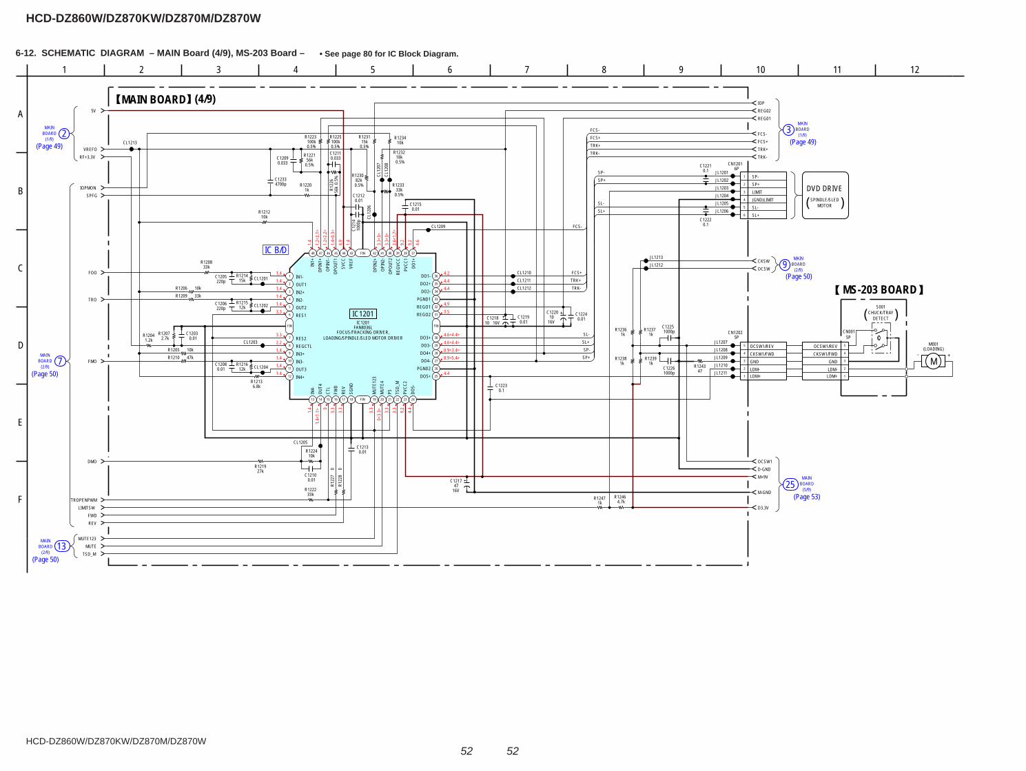
HCD-DZ860W/DZ870KW/DZ870M/DZ870W
HCD-DZ860W/DZ870KW/DZ870M/DZ870W
5252
6-12. SCHEMATIC DIAGRAM – MAIN Board (4/9), MS-203 Board – • See page 80 for IC Block Diagram.
(1/9)3 BOARD
MAIN
(2/9)9 BOARD
MAIN
(5/9)BOARDMAIN
25
MAIN2BOARD
(1/9)
7BOARD(2/9)
MAIN
BOARD(2/9)
MAIN13
IC B/D
1.41.41.41.41.43.3
3.32.21.41.41.41.4
1.4
1.4<
1.1> 03.
33.
3
3.3
0<3.
3> 3.3
3.3
9.2
4.4
4.24.44.4
4.93.5
4.6<4.4>4.6<4.4>0.9<3.4>0.9<5.4>
4.4
1.4
1.2<
2.1>
1.2<
2.2>
1.4<
0.3>
4.9
1.4
3.3<
3>3.
3<3>
2.6<
1.7>
9.2
9.2
4.6
0.01C1212
0.5%100k
R1223
33kR1208
220pC1205
0.5%56k
R1221
0.5%15k
R1231
27kR1219
16V10C1218
1.2kR1204
0.033C1211
0.01C1203
1000pC122612k
R1216
0.01C1219
15kR1214
0.5%
56kR1
226
0.01C1213
0.01C1210
1kR1237
4700pC1233
16V10
C1220
33kR1209
10kR1205
10kR1206
0R1
228
0.5%18k
R1232
1000pC1225
0.5%82k
R1230
0R1
227
0.5%100k
R1225
0.033C1209
0.1C1223
1kR1236
10kR1224
0.01C1208
1kR1247
47kR1210
33kR1222
10kR1234
0.01C1224
10kR1212
6.8kR1213
12kR1215
4.7kR1246
1kR1220
220pC1206
0.01C1215
1000
pC1
214
2.7kR1207
JL1206JL1205
JL1203JL1204
JL1202JL1201
1
2
3
4
5
6
7
8
9
10
11
12
13 14 15 16 17 18 19 20 21 22 23 24
25
26
27
28
29
30
31
32
33
34
35
36
373839404142434445464748
FIN FIN
FIN
FIN
IC1201FAN8036L
IN1-OUT1IN2+IN2-OUT2RES1
RES2REGCTLIN3+IN3-OUT3IN4+
IN4-
OUT4
CTL
FWD
REV
SGND
MUT
E123
MUT
E4PS TS
D_M
PVCC
2DO
5-
DO5+PGND2
DO4-DO4+DO3-DO3+
REGO2REGO1PGND1
DO2-DO2+DO1-
DO1+
PVCC
1RE
GVCC
OPOU
T2OP
IN2-
OPIN
2+
VREF
SVCC
OPOU
T1OP
IN1-
OPIN
1+IN
1+
JL1207JL1208JL1209JL1210JL1211
JL1212JL1213
CL1213
SPFG
5V
TRO
VREFO
CKSW
FMO
D3.3V
IOP
OCSW
DMO
IOPMON
OCSW1
TROPENPWM
FCS-
D-GND
LIMITSWFWD
FCS+
REV
TRK+
MUTE123
FOO
TRK-RF+3.3V
MUTE
REG01
TSD_M
REG02
M+9V
M-GND
0.1C1222
CL1201
CL1202
CL1203
CL1204
CL1205
CL12
06
CL12
07CL
1208
CL1209
CL1210CL1211CL1212
0.1C1221
0.5%33k
R1233
1kR1239
1kR1238
47R1243
1
2
3
4
5
5PCN1202
LDM+LDM-GNDCKSW1/FWDOCSW1/REV
1
2
3
4
5
6
6PCN1201
SP-SP+LIMIT(GND)LIMITSL-SL+
16V47
C1217
M
M001(LOADING)
S001
1
2
3
4
5
5PCN001
LDM+LDM-GND
CKSW1/FWDOCSW1/REV
FCS-
FCS-FCS+TRK+TRK-
FCS+TRK+TRK-
SL+SP-
SP+
SL+
SL-
SL-
SP-SP+
MAIN BOARD (4/9)
FOCUS/TRACKING DRIVER,
IC1201
LOADING/SPINDLE/SLED MOTOR DRIVER
DVD DRIVESPINDLE/SLED
MOTOR( )
85
F
C
641
B
7
A
2 9 11103
E
12
D
CHUCK/TRAY
-
MS-203 BOARD
+
( )DETECT
(Page 49)
(Page 50)
(Page 50)
(Page 49)
(Page 50)
(Page 53)
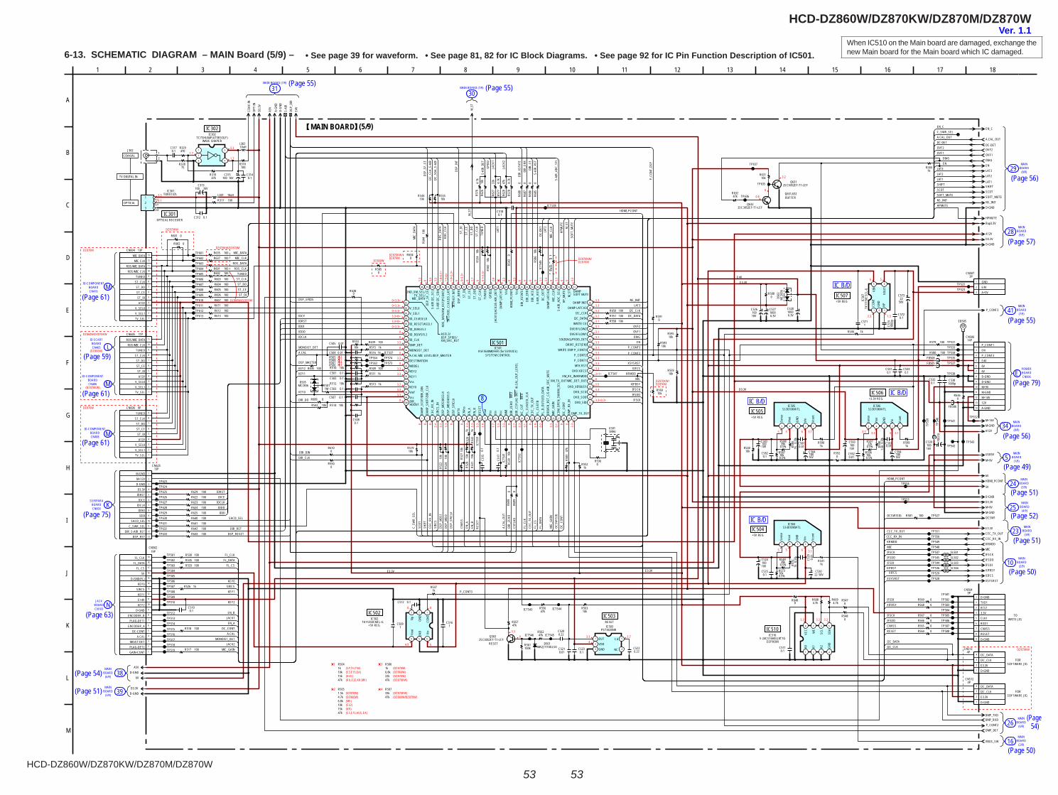
HCD-DZ860W/DZ870KW/DZ870M/DZ870W
HCD-DZ860W/DZ870KW/DZ870M/DZ870W
5353
6-13. SCHEMATIC DIAGRAM – MAIN Board (5/9) – • See page 39 for waveform. • See page 81, 82 for IC Block Diagrams. • See page 92 for IC Pin Function Description of IC501.When IC510 on the Main board are damaged, exchange the new Main board for the Main board which IC damaged.
MAIN
(6/9)BOARD26
MAIN
(6/9)BOARD
MAIN
(3/9)BOARD
38
39
MAIN
(8/9)BOARD29
MAIN
(9/9)BOARD28
MAIN
(8/9)BOARD34
BOARDMAIN
16(2/9)
BOARDMAIN
24(3/9)
BOARD5MAIN
(1/9)
MAIN
(4/9)BOARD25
MAIN
(3/9)BOARD23
MAIN
(2/9)BOARD10
31MAIN BOARD (7/9)
MAIN BOARD (7/9)
30
JACKNBOARD
CN103
CN405 LIO-SCART
BOARD
CN416M
IO-COMPONENTBOARD
ECN906
POWERBOARD
8
SERIPARABOARDCN600
K
CN406
IO-COMPONENTBOARD
M
CN408
IO-COMPONENTBOARD M
BOARD41(7/9)
MAIN
IC B/D
IC B/DIC B/D
IC B/D
3.30.1
1.7
3.31.7
0<3.3>0<3.3>0<3.3>3.3<0>3.3<0>
00
0<3.3>
3.300
3.30
3.33.3
3.33.33.3
0
0 0 03.
43.
33.
3 0 03.
33.
33.
31.
9
1.7
3.3
3.3 0
2.7
3.3
3.1 0
2.9
0.2
3.3
0.1 0 0
3.3
3.3<0.3>03.32.502<1>3.33.33.33.33.13.33.13.13.13.13.23.23.33.3
3.3
0 3.3
3.3
1.8<
0.1>
1.5<
0>1.
9<2.
3>0 0<
3.3>
0 2.7
0 0.1<
3.3>
2.9
3.3
0 3.3
0 0 0 0 3.1
3.3
0 3.3
0 0 3.3
3.2
0
0.6
5 5 6 3.1 3.3 3.3 4 3.1
5 5 6 3.1
3.3 3.3 3.3
3.73.34
3.30
0
6
0
4.9
6 5
3.3 1.3
(E3,E15,EA)
2
(SP,TH,TW)1
DZ870KW
DZ870KW/DZ870M
DZ860W/DZ870M
DZ860W
DZ870KW/DZ870M
DZ870M
DZ870W
1243
DZ870KW/DZ870M
DZ870KW/DZ870M
(AUS)(RU,E32,KR,MX)
(MX)
(DZ870M)
(E32)
(DZ860W)
(KR)(E3,E15,AUS,EA)
(DZ870W)
(DZ870M)
4
(DZ870KW)
(DZ870KW)(DZ860W/DZ870W)
3
(DZ860W)
DZ870KW
DZ860W/DZ870KW
(DZ860W)
(DZ870KW)
0.5%
0.01C505
R604 100100R605100R606100R607
R6100
100R611100R612100R613
R506R504
R532
1kR5
3410
kR5
3110
k
R55910k
10k
R524
10kR560
10k
R527
R528
10k
R569 0R568 0
R567 0R566 0R565 0R564 0
C504 0.01
R522
10k
R505R507
ICT545
ICT543
ICT547
ICT5
41
TP502
TP507
TP607
TP513TP514
TP610
TP519
TP609
TP605
TP608
TP611
TP518
TP613
TP510TP509
TP574
TP606
TP603
TP508
TP612
TP516
TP501
TP506
TP604
TP512
TP515
TP517
TP573
TP505
A.CAL_OUT
OVF2OVF1DIAG
1 2 3 4 5 6 7 8 9 10 11 12 13 14 15 16 17 18 19 20 21 22 23 24 25 26 27 28 29 30
31
32
33
34
35
36
37
38
39
40
41
42
43
44
45
46
47
48
49
50
515253545556575859606162636465666768697071727374757677787980
81
82
83
84
85
86
87
88
89
90
91
92
93
94
95
96
97
98
99
100
IC501R5F3640MDFAR (for SERVICE)
DAM
P_SC
DT/D
IR_D
INDA
MP_
SHIF
T/DI
R_CL
KCE
C_RX
_IN
SIRC
S_IN
DSP_
MOS
I/ASE
L4DS
P_M
ISO/
ASEL
5DS
P_SP
ICLK
BYTE
CNVs
sEN
_AEN
_BRE
SET
Xout
Vss
Xin
Vcc
NMI
DIR_
ZERO
IN
T2DI
R_CS
FLAG
INT
1 /A
.CAL
_OUT
_LEV
ELAC
_CUT
INT0
FL_C
LK/L
ED_C
LKCE
C_TX
_OUT
FL_C
S/ST
BFL
_D_O
UT/L
ED_D
ATA
DRIV
ER_R
ST_C
/S-A
IR_S
RC_M
UTE
MIC
_GAI
NCD
M_O
PEN_
SW/X
M_S
ELDC
_CON
TDM
P_RX
_IN
DMP_TX_OUT
DVD_SIDDVD_SODDVD_SCO
DVD_XIFBUSY
XM_TX_OUT/MIC_DET_OUTXM_RX_IN/KRMOD
DVD XIFCSMTK RST
P_CONT1 P_CONT2WRITE EMP P_CONT3
DRIVE_RST(EN)SD(DIAG)/PVDD_DET
OVERFLOW1OVERFLOW2
WRITE CEI2C_DATAI2C_CLK
DAMP LATCH3DAMP INIT
DAMPSOFT MUTEM
_ST
HP_M
UTE
S-AI
R_AD
C_SE
LM
IC_C
LKDA
MP
LATC
H2DC
_DET
S-AI
R_RS
TDI
R_HC
EDI
R_ER
RDI
R_XS
TATEVc
cHD
MI_
PCON
TVs
sDA
MP
LATC
H1JA
CK1/
JACK
2/S-
AIR_
DET
GPIO
2TU
NED
ST_C
LKST
_DO
ST_C
EST
_DI
DSP_
INTR
INT4
KEY
INT
INT3
RDS
_CLK
/LED
_LAT
RDS_
DATA
/XM
_RST
(PCO
NT)
S-AI
R I2
C_SD
AS-
AIR
I2C_
SCL
DSP_
SF_C
E2ND_XM_SEL/TV_SEL/
MIC_DATA
ASEL3/DSP_SPIDS/XM_SRC_RST
V_SEL0V_SEL1IO_CE/ASEL0IO_RESET/ASEL1IO_DI/ASEL2IO_DO/VSEL2IO_CLKDMP_DETMONO/ST_DETA.CAL MIC LEVEL/DSP_MASTERDESTINATIONMODELKEY2KEY1VssKEY0VrefVccDIR_HDOUT
100R601R602 100
R603 100S-
AIR
DSP_
DIR
10kR519
1kR5
29
0.1
C515
0R536
5MHzX501
0.1
C517 10
kR5
39
47kR556 ICT544
47kR557
2SC3052EF-T1-LEFQ503
RESET
ICT546
100kR561
47kR562
0.22C520
10kR563
0.01C521
5
43
2
1
PST3635NRIC503
OUTVDDGND NC
Cd
0.1C523
0.22C522
10kR558
R59310k
R59510k
0R591
0.1C518
ICT538
1kR5151kR516
100R509
10kR512
0.1C5010.1C502
0.1C508
0.1C503
0.1C507
10kR514
100R517
100R518
100R533100R535100R530
1kR526
0.1C510
10V100C524
50VC530
22
0.01
C529
R57310k
0.5%
R572
1k
10V100
C526
0.1C531
0.1C533
TP527
TP528
TP541
TP529
TP531TP533
TP538
TP534
TP537TP535
FB51
0
FB506
100R579
0.1C532
1000pC538
TP553
TP551
TP554
TP550
TP542
TP53
9
TP54
0
TP543
TP544
TP548
TP545
TP549
TP547
R581 100
R6360
KRMOD
IFSCKIFSDO
CEC_RX_IN
100R639
R640 100R641 100R642 100
R645 100
TP601TP602
1kR552
10k
R553
R5470
R5480
1
2
3
44P
CN512
D-GNDE3.3VI2C_CLKI2C_DATA
ICT5
49
6.3V1000C528
R55510k
TP625TP626TP627TP628TP629TP630TP631TP632
TP623
10kR542
DC-DET
10k
R586
1MR501
ICT5
91
ICT5
92
R644
100
0R5
43
10kR544
R622 100R623 100R624 100R625 100
R583
47k
SL501SL502SL503SL504
1kR511
1kR513
TP564TP563
ICT537
10kR631
2SC3052EF-T1-LEFQ631
47kR632
TP635
TP636
TP637
MC2836D505
2SC3052EF-T1-LEFQ632
E
EB505
R5841k
L30210uH
R317 100
16VC313
100
R32875
R329470J302
12
16VC315
100
L301 10uH
5
43
2
1
TC7SHU04FU(T5RSOJF)IC302
R31947k
R318100
VCC
OUT
GND
TORX147LIC301
123
P_CONT2
6V
DMP_TXDDMP_RXD
R685
0R6
860
R687
0R6
880
R689 0
R698
0R6
990
R5500
16V100
C539
1
2
3
4
5
6
7
8
9
9PCN504
D-GNDTXD1RTS13.3VCLK1RXD1CNVSSRESETD-GND
R5371k
TP503TP504
C3140.1
C312 0.1
C3170.1
0.01C581
0.01C592
0.5%
1.5kR5
98
10kR5870.5%
39kR5880.5%
0.1C582
0.5%22k
R59710V100
C583 0.5%
1kR589
0.5%10k
R596
0.01C591
12345
SI-3010KM-TLIC506
Vcon
t
Vin
GND
Vout
Sens
e
10V100
C593
12345
SI-3010KM-TLIC505
Vcon
t
Vin
GND
Vout
Sens
e
100R580
R5901k
R5991k
TP536
16V100
C59416V100C584
1
2
3
3PCN507
GNDE4VA+5V
TP522TP523
R5850
47k
R628
22k
R627
10k
R626
4.7k
R577
4.7k
R576
4.7k
R578
100R650100R551
R629 100
R643 100
TP624
TP633
1
2
3
4
5
6
7
8
9
10
11
12
13
13PCN625
M-GNDM+12VD-GNDD3.3VIORST
IOCEIOCLKIODOIODI
SACD_SELC_SWR_SEL
DIR_S-AIR_RSTDSP_RST
1
2
3
44P
CN513
D-GNDE3.3VI2C_CLKI2C_DATA
R633
0
R6340
0R682
0R681
R637 100100R635
M-GND
1
3
4
5
6
7
8
9
10
11
12
13
14
14PCN506
P_CONT1ENP_CONT3E4V6V6VD-GNDD-GNDM+9VM-GNDM+14V12VA-GND
M+14VTP552
LAT3EN
NS_INIT
D3.3VA12V
SOFT_MUTE
HPMUTE
SCDT
EN_C
SHIFTLAT1
D-GND
LAT2
D-GND
MIC
E3.3V
D3.3V
XSYSRST
OCSW1
5V
XIFCS
IFSDIXIFBSY
CEC_TX_OUT
M+9VM-GND
COAX
-IN
D-GN
D
D3.3
V
A-GN
D
A5V M_S
T
OPT-
IN
E4V
12345
SI-3010KM-TLIC504
Vcon
t
Vin
GND
Vout
Sens
e
0.1C525
0.5%R549
39k
USB5V
1000
pC5
74
1C571
0.1C572
50V22
C573
5 4
321
TK11
150C
SCL-
GIC
507
CONT
GND
NPVO
UTVIN
R546 1k
10kR510
MA2J1110GLS0D501
MC2
836
D502
VBUS_SW
R5411k
DMP_DET
R6380
R54010k
1C516
1C509
TP581TP582TP583TP584TP585TP586TP587TP588
R6084.7k
R6094.7k
C5110.1
R6480
R582
10k
FB508FB505
0.1C512
1
2
3
4
5
6
7
8
9
10
11
12
13
13PCN604
1
2
3
4
5
6
7
8
9
10
11
11PCN605
8 7 6 5
4321
S-24CS16A0I-J8T1GIC510
A0 A1 A2 GND
SDA
SCL
WE
VCC
1
2
3
4
5
6
7
8
9
9PCN606
1
2
3
4
5
6
7
8
9
10
11
12
13
14
15
16
17
18
19
19PCN502
R5080
123
4 5 6
TK11250CMCL-GIC502
CONT
GND
NpVo
ut
GND Vin
C52710006.3V
Bup3.3V
R5920
HDMI_PCONT
P_CONT3
A5VD-GND
6V
D3.3VD-GND
D-GND
A12V
M+9V
SIRC
S
FL_D
ATA
MIC
_GAI
N
DC_C
ONT
A.CAL_OUT
HPMUTE
OVF2OVF1
LAT3LAT2LAT1SHIFTSCDTSOFT_MUTENS_INIT
RDS_CLKTUNED
ST_DIST_CEST_DO
ST_CLK
RDS_DATA
IFSDIIFSDOIFSCK
XIFBSY
XIFCSXSYSRST
ENDIAGOVF1OVF2
LAT3NS_INIT
RDS_
DATA
HPM
UTE
SOFT
_MUT
E
P_CO
NT_D
SP
MIC
XIFCS
EN_A
EN_B
TUNE
DST
_CLK
ST_D
O
ST_D
IST
_CE
KRMODMIC
CEC_TX_OUTCEC_RX_IN
CEC_
RX_I
N
CEC_
TX_O
UT
DSP_MASTER
DSP_
INT
DC-DET
DC-D
ET
C_SWR_SELEN_C
A.CAL
IFSCKIFSDOIFSDI
EN
DIR_
ERR
DIR_
XSTA
TE
DIR_DO
DIR_
ZERO
CSFL
AG
DSP_
SPIC
LK
IFSCKIFSDOCNVSSRESET
XIFBSYIFSDI
XSYSRST
XIFBSY
DIR_DINDIR_CLK
LAT1
I2C_
CLK_
S-AI
R
RDS_
CLK
IODI
DSP_
MOS
I
IOCLK
IOCEIORST
DSP_RESET
IODO
M_S
T
I2C_CLK
MIC
_DAT
A
MIC_DATAMIC_CLK
DIR_RSTDI
R_CE
FL_C
S
LAT2
MIC
_CLK
I2C_DATA
S-AI
R_RS
T
MIC_GAINJACK2
MONO/ST_DETA.CAL
DC_CONTEN_A
JACK1
FL_CLKFL_DATA
FL_CS
KEY0SIRCSKEY1
KEY2
EN_B
P_CONT3
HDMI_PCONT
DIAG
FL_C
LK
KRMOD
I2C_DATAI2C_CLK
KEY2KEY1
MONO/ST_DET
KEY0
JACK
1
S-AI
R_DE
T
JACK
2
GPIO
2
DSP_
SF_C
E
I2C_
SDA_
S-AI
R
RESE
T
SHIF
TSC
DT
OCSW
1SIG
CNVS
S
A.CA
L_OU
T
DSP_
MIS
O
P_CONT2
HDMI_PCONT
E3.3V
E3.3VE3.3V
OCSW1SIG
M_S
T
IORSTIOCE
IOCLKIODOIODI
DSP_SPIDS
SACD_SEL
D3.3V
E4V
C_SW
R_SE
L
S-AI
R_AD
C_SE
L
P_CONT3
OPTICAL
COAXIAL
+3.3V REGIC506
+5V REGIC505
IC507+5V REG
IC504+5V REG
IC510
EEPROM
IC503RESET
IC502
+5V REG
SYSTEM CONTROL
IC501
WAVE SHAPER
IC302
OPTICAL RECEIVERIC301
(5/9)MAIN BOARD
TV DIGITAL IN
Q631,632BUFFER
TOWRITE JIG
FORSOFTWARE JIG
FORSOFTWARE JIG
10k1k
R505
R504
PLAG-DET2
A.CAL
ENCODER_B
FL_CS
PLAG-DET1
D-GND(FL)
FL_DATA
KEY1
KEY2
DC-CONT
GAIN-CONT
5V
E+4V
KEY0
FL_CLK
D-GND
ENCODER_A
MO/ST-DET
SIRCS
ST_CEST_DO
MIC CLK
V_SEL0V_SEL1
A12VST_DI
ST_CLK
RDS/MIC CLK
TV_SEL
RDS/MIC DATA
TUNED
MIC DATA
ST_DI
RDS/MIC DATA
V_SEL0A12V
TV_SEL
ST_CEST_DO
V_SEL1
RDS/MIC CLK
ST_CLKTUNED
ST_DIST_CE
ST_CLKTUNED
A12V
V_SEL1
ST_DO
TV_SEL
V_SEL0
47k15k
10k
4.7k1.5k
6.8k
47k15k
R506
47k
R507
6.8k1k
33k
22k
47k
I
L
6 10
D
7
F
16
A
M
G
111 4 17
C
13
J
122 9 18
H
145
E
K
8
B
153
(Page 61)
(Page 61)
(Page 61)
(Page 75)
(Page 63)
(Page 54)
(Page 51)
(Page 59)
(Page 55) (Page 55)
(Page 56)
(Page 57)
(Page 55)
(Page 79)
(Page 56)
(Page 49)
(Page 51)
(Page 50)
(Page 50)
(Page 54)
(Page 52)
(Page 51)
Ver. 1.1
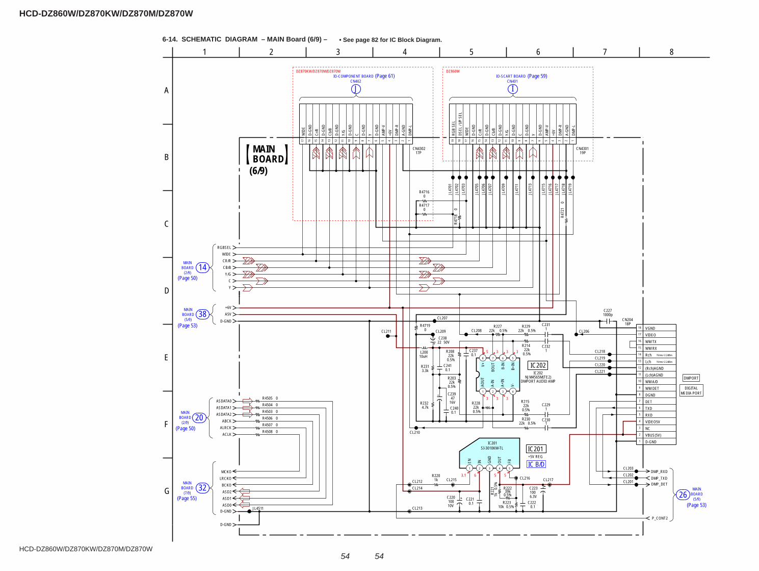
HCD-DZ860W/DZ870KW/DZ870M/DZ870W
HCD-DZ860W/DZ870KW/DZ870M/DZ870W
5454
6-14. SCHEMATIC DIAGRAM – MAIN Board (6/9) – • See page 82 for IC Block Diagram.
MAINBOARD26
(5/9)
BOARDMAIN
32(7/9)
BOARDMAIN
20(2/9)
BOARDMAIN
38(5/9)
JCN402
MAIN
(2/9)BOARD
CN401IO-SCART BOARD
I
14
IO-COMPONENT BOARD
IC B/D
5 3 3 3
3 3 3
3.1 6 5 5
DZ870KW/DZ870M/DZ870W DZ860W
R4508 0
R4505 0
R4507 0
R4503 0R4504 0
R4506 0
JL4511
R47190 0.5%
R22722k
CL216
0.5%
R221
1k
CL206
CL213
DMP_RXD
R214
0.5%22k
CL210
CL202
C239
16V47
CL2140.5%R22239k
CL221
DMP_TXD
CL220
C2311
CL218
0.5%
R20822k
CL211
6.3V
C223100
C2271000p
R2313.3k
P_CONT2
CL208
1 2 3 4 5
SI-3010KM-TLIC201
DMP_DETCL217
0.5%R230
22k
CL203
C2301
R215
0.5%22k
CL219
18PCN204
0.1C237
C2220.1
C2291
0.5%R223
10k
CL207
R2324.7k
0.5%
R22822k
10V
C220100
C2400.1
C2321
C2410.1
CL215 CL201
10uHL200
8 7 6 5
4321
C2210.1
0.5%
R20322k
0.5%R229
22kCL209
CL212R220
1k
50VC238
22
JL47
07
19PCN4301
JL47
16
JL47
09
JL47
18JL
4719
JL47
02
17PCN4302
JL47
17
R471
80
JL47
01
JL47
11
R47160 JL
4715
JL47
06
JL47
13
R47170
R472
10
JL47
05
JL47
03
1Vrms=2.2dBm
+5V REG
1Vrms=2.2dBm
IC201
(6/9)
MAINBOARD
A
3
E
81 4 6
B
75
D
G
2
C
F
DMPORT
MEDIA PORTDIGITAL
D-GNDVBUS(5V)NCVIDEO5VRXDTXDDETDGNDWM DETWM A/D(Lch)AGND(Rch)AGNDLchRchWM RXWM TXVIDEOVGND
1
2
3
4
5
6
7
8
9
10
11
12
13
14
15
16
17
18
1234567891011121314151617 12345678910111213141516171819
DMP-
LA-
GND
DMP-
R+6
VAM
P-V
D-GN
DYD-
GND
CD-GN
DY/
GD-
GND
Cb/B
D-GN
DCr
/RD-
GND
WID
EDS
EL /
I/P S
ELRG
B SE
L
D-GN
D
AMP-
V
Y/G
D-GN
D
C D-GN
D
Cb/B
Y DMP-
R
D-GN
D
D-GN
D
WID
E
A-GN
D
+6V
DMP-
L
Cr/R
D-GN
D
ASDATA2ASDATA1
D-GND
ABCKALRCK
ACLK
D-GND
D-GND
ASDATA0
+6V
ASD0
BCKOASD2ASD1
LRCKOMCKO
A5V
CR/R
C
RGBSEL
Y/GCB/B
WIDE
Y
EN IN GND
OUT
FB
AOUT
A-IN
A+IN
V-B+
IN
B-IN
BOUTV+
NJM4565M(TE2)IC202
IC202
DMPORT AUDIO AMP
(Page 61) (Page 59)
(Page 50)
(Page 53)
(Page 50)
(Page 55)(Page 53)
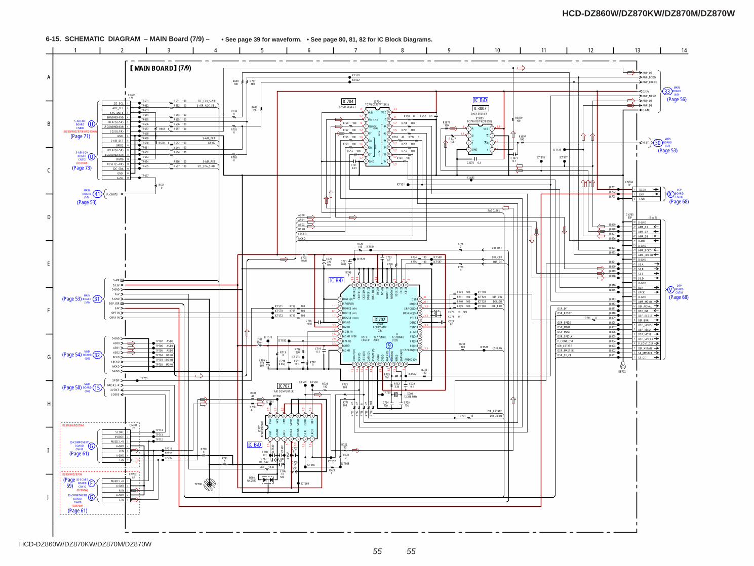
HCD-DZ860W/DZ870KW/DZ870M/DZ870W
HCD-DZ860W/DZ870KW/DZ870M/DZ870W
5555
6-15. SCHEMATIC DIAGRAM – MAIN Board (7/9) – • See page 39 for waveform. • See page 80, 81, 82 for IC Block Diagrams.
9
CN410
IO-SCARTFBOARD
CN410
IO-COMPONENTGBOARD
MAINBOARD
(2/9)15
MAINBOARD 32
(6/9)
MAINBOARD 31
(5/9)
X
30MAIN
(5/9)BOARD
33MAIN
BOARD(8/9)
BOARD 41MAIN
(5/9)
BOARDS-AIR-CON
BOARDS-AIR-INC
U
U
CN800
CN112
CN418GIO-COMPONENT
BOARD
V CN701BOARD
DSP
BOARDDSP
CN700
IC B/D
IC B/D
IC B/D
3.3
0
0
0
0
0
0
1.2
3.3
1.7
1.7
1.7
1.7
1.7
1.51.2
1.7
1.6
1.61.2
1.10.11.7
3.31.52.92.93.3
00.13.3
3.3
3.3
3.33.
33.
3
3.3
0 0 0
1.5
1.6
1.6 0
3.3
3.3 1.5
1.5 0
2.5
2.5
3.3
1.2
1.6
2.5 5 3.3
1.5
1.6
DZ870KW/DZ870M
DZ860W/DZ870W
(DZ860W/DZ870KW/DZ870W)
(DZ870M)
(DZ860W)
(DZ870W)
R652 100
R655 100R656 100R657 100
R654 100
TP651TP652TP653
TP658
TP655TP656TP657
S-AIR
TP707TP706TP705TP704TP703TP702
TP701
TP711TP710TP709
A5VA-GND
OPT-INCOAX-IN
D-GND
E4V
100R724
100R723
R722100
0R721
100R771 47
R725
47R7
270
R728
47R7
2910
0R7
30
1kR731
0.1C722
TP729
1MR733
12.288 MHzX701
100R736
ICT527
ICT526
ICT528ICT529
100R738
100R739100R740100R741
0.1C727
100R735100R734
100R726
100R719100R718100R717
0.1C723
0.01C721
ICT523
ICT524
10V220
C720
0.01C716
0.1C719
0.1C711
0R713 220
R716
ICT533
ICT532
10V220
C709
R754 100
R753 100
R756 100
R755 100 R752 100
R751 100
R759 100
R760 100
R761 100
R762 47
C7510.01
C752 0.1
ICT517ICT518
ICT519
ICT520
ICT521
R758 0
D-GND
D3.3V
D3.3V
R774 0
D-GND
D-GND
ASD0ASD1ASD2BCKO
LRCKOMCKO
SPDIF
R7780
47R780
47R781
JL001JL002JL003JL004JL005JL006JL007JL008JL009JL010
JL012JL013
JL015
JL018JL019JL020JL021
JL023JL024
JL026
ICL522
CL682
ICT588ICT587
ICT580
ICT581
ICT5
89
ICT5
82
ICT5
55
ICT556ICT557
ICT558ICT559
ICT560
ICT561
TP712
TP654
TP660
ICT568
ICT569
ICT570ICT571
ICT572
ICT573
0R790
R7910
R7920
C774 0.150VC775 10
DSP_DIR
50V10
C706
50V10C717
50V10
C705
0.1C707
0.1C708
0.1C718
1
2
3
4
5
5PCN702
MUSIC L+RA-GND
R-INA-GND
L-IN
C30730.1
8
7
6
54
3
2
1
TC7WH157FK(TE85R) IC3003
A
B
Y
GND Y
A/B
G
VCC
R3079100
M_ST
0.1C3072
R3097100R3077
100
R3078100
C7100.068
R757 100
MUSICL+R
14 13 12 11 10 9 8
7654321
IC70
7PC
M18
08PW
R
Vref
AGND
AVcc
DVdd
DGND
SCKI
LRCK
BCK
DOUT
MOD
0
MOD
1
FMT
VinL
VinR
15pC724
15pC725
3.3kR732
MC2837D701
E
EB702
R663 100R664 100
R662 100
JL027JL028
R743 100
1
2
3
4
5
6
7
7PCN701
SCOREXVIOCE
MUSIC L+RA-GND
R-INA-GND
L-IN
TP713TP714
JL029
JL016
TP661TP662TP663TP664
JL701JL702JL703
JL011
TP665
R651 100
100R683
R7930
100R787
100R690
R666 100R667 100
TP659
R7940
1
2
3
4
5
6
7
8
9
10
11
12
13 14 15 16 17 18 19 20 21 22 23 24
25
26
27
28
29
30
31
32
33
34
35
36
373839404142434445464748
LC890561WIC702
DISEL(I)SPDIF(O)DIN0(I)DIN1(I)DIN2(I)DGNDDVDDSDIN / RAGND / VINLPF(O)AVDDAGND
CKOU
T(O)
BCK(
O)LR
CK(O
)DA
TA(O
)XS
TATE
(O)
DGND
DVDD
XMCK
(O)
XOUT
(O)
XIN(
I)EM
PHA(
O)
AUDIO-(O)
CSFLAG(O)F0(O)F1(O)F2(O)VF(O)DVDDDGNDVREF
BPSYNC(O)ERROR(O)
DO(O)DI(I)
CE(I)
CL(I)
XSEL
(I)M
ODE0
(I)M
ODE1
(I)DG
NDDV
DDDO
SEL0
(I)DO
SEL1
(I)CK
SEL0
(I)CK
SEL1
(I)XM
ODE(
I)
AMP_D2
AMP_D3
AMP_BCKOAMP_LRCKO
AMP_MCKOAMP_D1
XVOICESCORE
R660 0
R7750
R7760
R7950
R7980
TP700
10uHL701
10uHL702
10uHL703
R711 0
30PCN703
1
2
3
3PCN704
D3.3VE4VGND
16
15
14
13
12
11
10
98
7
6
5
4
3
2
1
TC74LCX157FT(EKJ)IC704
A/B
1A
1B
1Y
2A
2B
2Y
GND 3Y
3B
3A
4Y
4B
4A
G
VCC
1
2
3
4
5
6
7
8
9
10
11
12
13
14
15
16
17
17PCN651
TP667
R661 0
R6210
P_CONT3
R7880
DIR_ZERO
DIR_DODIR_ERR
CSFLAG
DSP_RESETDSP_INT
DIR_XSTATE
DSP_MOSI
P_CONT_DSP
DSP_MISO
DIR_DIN
DIR_CE
DIR_RST
S-AIR_ADC_SELI2C_CLK_S-AIR
GPIO2
S-AIR_RSTI2C_SDA_S-AIR
S-AIR_DET
ASD0ASD1ASD2BCKO
MCKOLRCKO
MCKO
ASD1
DIR_XSTATE
LRCKOBCKO
ASD0
DSP_SF_CEDSP_MASTER
DSP_SPICLK
DSP_SPIDS
ASD2
DIR_CLK
SACD_SEL
(ADC)
(MTK HDMI)
BCLK
LRCK
MCL
K
(MTK)
(OPT)
(COAX)
LXSEL 24.576MHzCKSEL1 256fs 512fs
SACD SELECTIC704
DATA SELECTIC3003
DIR
IC702
A/D CONVERTERIC707
MAIN BOARD (7/9)
B
3 10 14
E
J
12
H
8 13
G
5
C
61 4
D
A
7 92
F
I
11
(B to B)
1
2
3
4
5
6
7
8
9
10
11
12
13
14
15
16
17
18
19
20
21
22
23
24
25
26
27
28
29
30
SF_CESF_MASTERDIR_XSTATEP_CONT_DSPDSP_SPICLKDSP_MOSIDSP_MISODSP_SPIDSDIR_ERRDSP_RESETDSP_INTDIR_NONAUAMP_MCKOD-GNDLRCKBCKD-GNDSI_DSI_CSI_BSI_AD-GNDAMP_LRCKOAMP_BCKOD-GNDD-MIXAMP_D3AMP_D2AMP_D1D-GND
12.288MHzH
I2C_SCLADC_SEL
SRC_MUTESD1(DMIX/XM)
BCK2(SL/SR)LRCK1(DMIX/XM)
SD2(SL/SR)GND
S-AIR_DETGPIO2
LRCK2(SL/SR)BCK1(DMIX/XM)
IFMT0RESET(S-AIR)
I2C_SDAGNDA+5V
(Page 71)
(Page 73)
(Page 53)
(Page 53)
(Page 54)
(Page 50)
(Page 61)
(Page 59)
(Page 61)
(Page 56)
(Page 53)
(Page 68)
(Page 68)
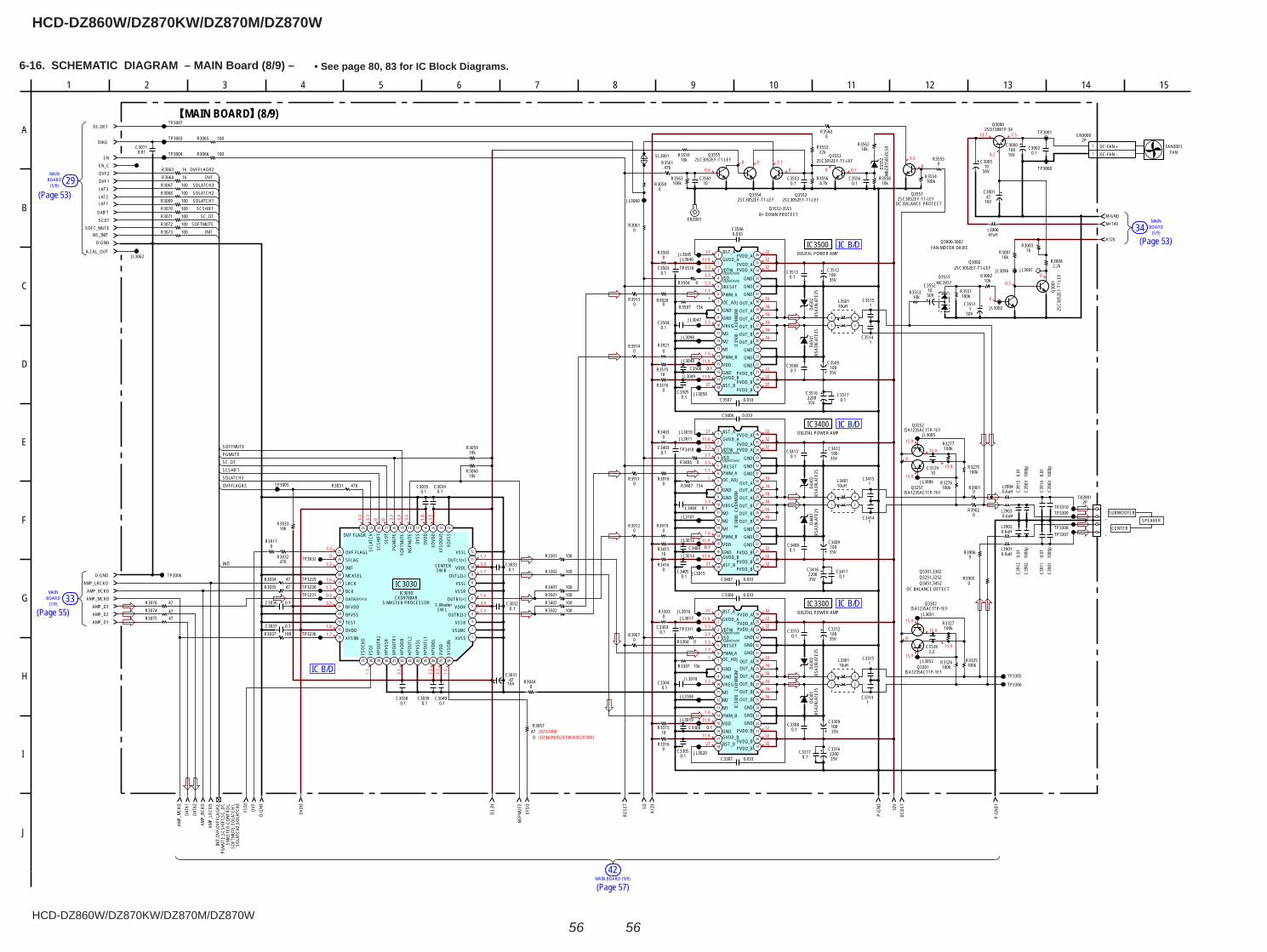
HCD-DZ860W/DZ870KW/DZ870M/DZ870W
HCD-DZ860W/DZ870KW/DZ870M/DZ870W
5656
6-16. SCHEMATIC DIAGRAM – MAIN Board (8/9) – • See page 80, 83 for IC Block Diagrams.
MAINBOARD34
(5/9)
MAIN BOARD (9/9)42
MAINBOARD
(7/9)33
BOARD 29MAIN
(5/9)
IC B/D
IC B/D
IC B/D
IC B/D
3.30
3.3
1.61.70.63.3
1.81.7
1.7
3.3
3.3
3.3
1.5
1.73.31.7
1.63.31.7
2711.9
3.33.13.31.7
1
3.3
1.611.9
11.927
323232
161616161616
323232
16
3232
16
32
32
27
16
32
1
2711.9
3.3
3.3
11.9 32
3.33.1
1616
11.9
1.7
16
1.6
16
3232
16
32
32
27
16
32
1
2711.9
3.3
3.3
11.9 32
3.33.1
1616
11.9
1.7
16
1.6
0.6 0 0.70
3.3
03.100
7.513.7
8.2
00.7
0
15.9
15.9
0
15.9
15.9
15.9
15.9
0
15.9
15.9
(DZ870M)(DZ860W/DZ870KW/DZ870W)
3.3
3.3
0 0 3.3
3.3
3.3
1.8
3.3
C3505
0.1C3308
0.1C3313
0.1C3413
C35080.1
C35130.1
0.1C3408
16V47
C3001
16V47
C3031
35V100
C3412
35V
C3509100
35V
C3512100
35V100
C3409
35V100
C3312
35V100
C3309
0.1C3002
16V100
C3000
C3416220035V
C3316220035V
50V1
C3551
50V10
C3552
1C3315
C35141
1C3314
1C3414
C35151
1C3415
0.1C3040
0.1C3039
0.1C3038
0.1C3037
0.1C3036
0.1C3035
0.1C3034
0.1C3033
0.1C3032
R3502 100
R3501 100R3402 100
R3401 100
100R3302
100R3301
47R3076
47R3075
100R3073100R3072100R3071100R3070100R3069100R3068100R3067
100R3066
R3057
100R3037
47R303547R3034
470R3032
470R3031
1kR3063
100R3065
1kR3064
2.2kR3004
1kR3003
10kR3001
10kR3002
10kR3033
10kR3059
10kR3060
10kR3553
100kR3554
100kR3551
100kR3326 100k
R3325
100kR3276
100kR3275
0R3304
0R3404
R3504 0
0R3555
47uHL3000
1
22P
CN3000
DC-FAN -DC-FAN +
2SC3052EF-T1-LEFQ3002
2SC3052EF-T1-LEFQ3551
DC BALANCE PROTECT
2SC3
052E
F-T1
-LEF
Q300
1
JL3062
JL3060
JL3052
JL3051
JL3050
JL3049
JL3048
JL3047
JL3046JL3045
JL3020
JL3019
JL3018
JL3017JL3016
JL3015
JL3014
JL3013
JL3011JL3010
JL3002
JL3001
TP3004
TP3311
TP3006
TP3003
TP3000
TP3410
TP3005
TP3236
TP3032
TP3001
TP3510
A.CAL_OUT
NS_INITSOFT_MUTE
SCDTSHIFT
LAT1LAT2LAT3
EN
DIAG
OVF1OVF2
D-GND
AMP_D1AMP_D2AMP_D3
AMP_BCKOAMP_LRCKO
AMP_MCKO
36
35
34
33
32
31
30
29
28
27
26
25
24
23
22
21
20
1918
8
4
1
2
3
5
6
7
9
10
11
12
13
14
15
16
17
CXD9
883M
IC34
00
BST_AGVDD_A
/DTW/SD
/RESETPWM_AOC_ADJ
GNDGNDVREGM3M2M1PWM_BVDDGNDGVDD_BBST_B
36
35
34
33
32
31
30
29
28
27
26
25
24
23
22
21
20
1918
8
4
1
2
3
5
6
7
9
10
11
12
13
14
15
16
17CX
D988
3MIC
3300
BST_AGVDD_A
/DTW/SD/RESETPWM_AOC_ADJ
GNDGNDVREGM3M2M1PWM_BVDDGNDGVDD_BBST_B
36
35
34
33
32
31
30
29
28
27
26
25
24
23
22
21
20
1918
8
4
1
2
3
5
6
7
9
10
11
12
13
14
15
16
17
CXD9
883M
IC35
00
BST_AGVDD_A
/DTW/SD
/RESETPWM_AOC_ADJGNDGNDVREGM3M2M1PWM_BVDDGNDGVDD_BBST_B
PVDD_BPVDD_B
PVDD_BGNDGNDGND
OUT_BOUT_BOUT_BOUT_AOUT_AOUT_A
GNDGNDGND
PVDD_APVDD_A
PVDD_A
15kR3407
JL3101
35V
C35162200
JL3104
JL3098
15kR3307
R3507 15k
JL3086
JL3085
JL3096
C35060.033
C3507 0.033
0.033C3307
0.033C3306
0.033C3407
0.033C3406
C3500 0.1
C35030.1
0.1
0.1C3400
0.1C3403
0.1C3405
0.1C3303
0.1C3305
0.1C3300
D-GND
0R3044
0R3061
0.01C3071
TP3231TP3230TP3229
TP3307TP3308
TP3309TP3310
100kR3327
100kR3277
R3074 47
C390
410
00p
C390
210
00p
C390
310
00p
C390
110
00p
0.01
C391
4
0.01
C391
3C3
912
0.01
C391
10.
01
C31282.2
10C3129
DC-DETTP3007
2SC3052EF-T1-LEFQ3553
C35560.1 10k
R35584.7k
R3556
22kR3552
C35530.1
2SC3052EF-T1-LEFQ3552
0R3901
0R3902
0R3905
0R3906
TP3305
TP3306
0R3914
0R3913
R39070
0R3917
EN_C
0R3911
R39120
SL3001
R39180
R39190
R39200
R39210
+
-
+
-
TB39012P
10R3415
0R3303
0R3416
0R3316
0R3403
10R3315
R351510
R35030
R35160
MC2837D3551
RSA3
9LAT
E25
D430
1RS
A39L
ATE2
5D4
302
RSA3
9LAT
E25
D440
1RS
A39L
ATE2
5D4
402
RSA3
9LAT
E25
D450
1RS
A39L
ATE2
5D4
502
E
EB3001
0.1C3317
0.1C3417
0.1C3517
R35600
0.1C3304
0.1C3404
C35040.1
1
2
3
4
5
6
7
8
9
10
11
12
131415161718192021222324
25
26
27
28
29
30
31
32
33
34
35
36
37 38 39 40 41 42 43 44 45 46 47 48
CXD9788ARIC3030
XVSSVSUBC
VSSROUTR2(-)
VDDROUTR1(+)
VSSRVSSL
OUTL2(-)VDDL
OUTL1(+)VSSL
XOVS
SXF
SOOU
TXO
VDD
DVDD
DVSS
NSPM
UTE
SOFT
MUT
EPG
MUT
ESC
DTSC
SHIF
TSC
LATC
HOVF FLAGR
OVF FLAGLSFLAGINITMCKSELLRCKBCKDATABFVDDBFVSSTESTDVDDXFSIIN
FSOC
KOFS
OIHP
OUTR
2HP
VSSR
HPOU
TR1
HPVD
DRHP
OUTL
2HP
VSSL
HPOU
TL1
HPVD
DLXV
DDXF
SOIN
2SC3052EF-T1-LEFQ3554
2SC3052EF-T1-LEFQ3555
10kR3559
47kR3561
0R3058
10kR3562
100kR3563
10C3561
ISA1235AC1TP-1EFQ3301
ISA1235AC1TP-1EFQ3252
ISA1235AC1TP-1EFQ3302
ISA1235AC1TP-1EFQ3251
0.6uHL3903
0.6uHL3901
0.6uHL3904
0.6uHL3902
10uHL3301
10uHL3401
3
21
4
L350110uH
MAZ
8150
G0LS
0D3
552
50V10
C3005
2SD1388TP-34Q3000
DCDE
T32
V
P-GN
D
A12VSD
RESE
T
XFSO
NSPM
UTE
D3.3
V
DVDD
INIT
OVFFLAGR2
SCSHIFTSC_DT
SOFTMUTE
SOLATCH3
PGMUTE
OVFFLAGR2
(DATA3)
(OpenDrain)
(OpenDrain)
(OpenDrain)
(OpenDrain)
(OpenDrain)
(OpenDrain)
CENTER SW R
S.Woofer SW L
DIGITAL POWER AMPIC3500
S-MASTER PROCESSOR
IC3030
(8/9)MAIN BOARD
FAN3001FAN
Q3552-3555B+ DOWN PROTECT
FAN MOTOR DRIVEQ3000-3002
DC BALANCE DETECT
Q3301,3302Q3251,3252Q3451,3452
SUBWOOFER
CENTERSPEAKER
122
G
1
A
9 10
I
6
B
H
4 5 14
D
J
3 157
E
F
8 11 13
C
P-GN
D1
470
A12V
M-GNDM+14V
3
21
4
PVDD_BPVDD_B
PVDD_BGNDGNDGND
OUT_BOUT_BOUT_BOUT_AOUT_AOUT_A
GNDGNDGND
PVDD_APVDD_A
PVDD_A
PVDD_BPVDD_B
PVDD_BGNDGNDGND
OUT_BOUT_BOUT_BOUT_AOUT_AOUT_A
GNDGNDGND
PVDD_APVDD_A
PVDD_A DIGITAL POWER AMPIC3400
DIGITAL POWER AMPIC3300
3
21
4
D-GN
DOV
FFS
OI
AMP_
LRCK
OAM
P_BC
KODA
TA2
DATA
1AM
P_M
CKO
INIT,
OVF,O
VFFL
AGR2
,PG
MUT
E,SC
SHIF
T,SC_
DT,
SMAS
TER-
CONT
ROL,
SOFT
MUT
E,SO
LATC
H1,
SOLA
TCH2
,SOL
ATCH
3INIT
SOFTMUTESC_DT
SCSHIFT
SOLATCH2
OVF
SOLATCH1
SOLATCH3
(Page 53)
(Page 55)
(Page 57)
(Page 53)
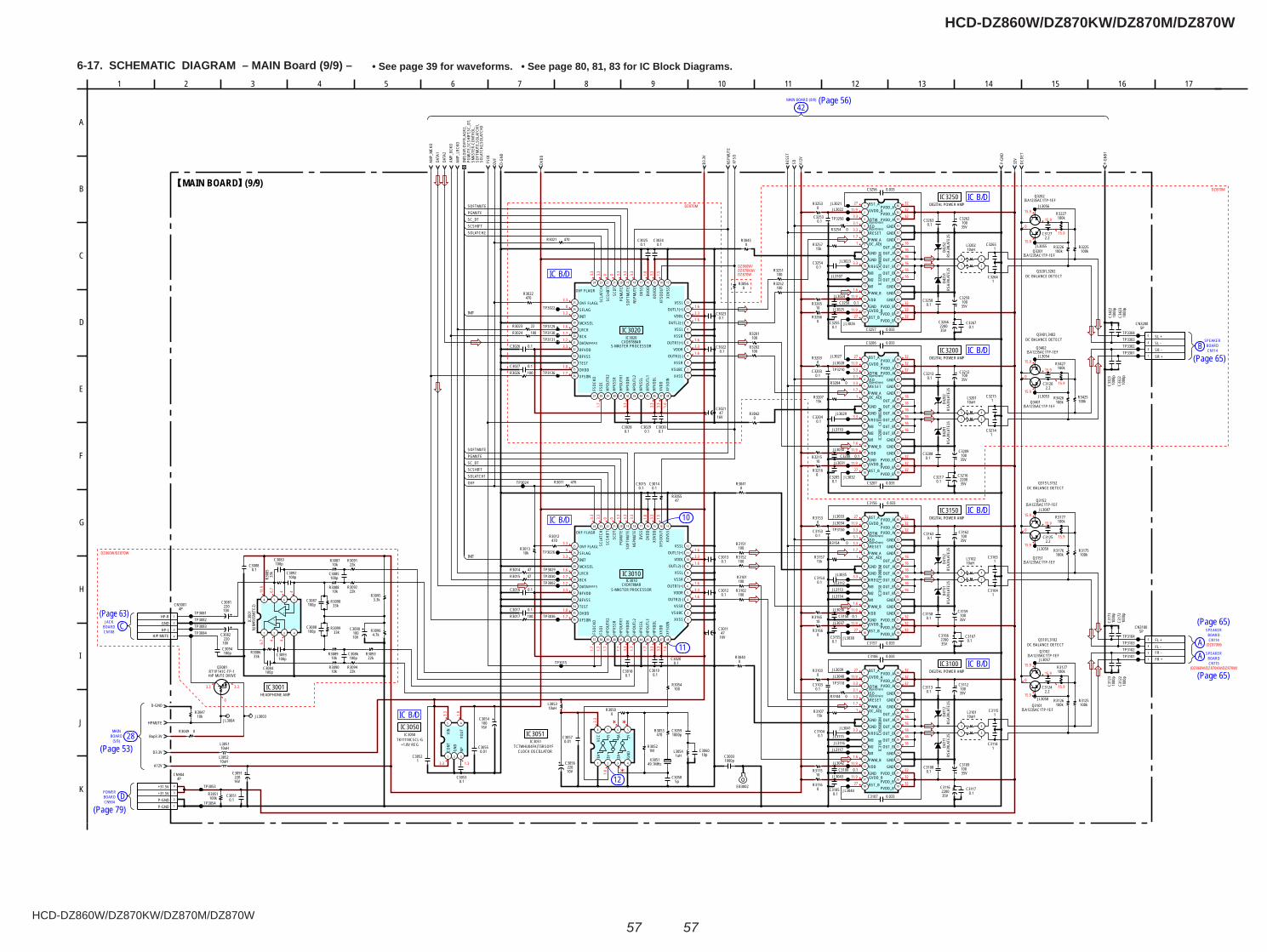
HCD-DZ860W/DZ870KW/DZ870M/DZ870W
HCD-DZ860W/DZ870KW/DZ870M/DZ870W
5757
6-17. SCHEMATIC DIAGRAM – MAIN Board (9/9) – • See page 39 for waveforms. • See page 80, 81, 83 for IC Block Diagrams.
CN904DBOARD
POWER
JACKBOARD CCN108
(5/9)BOARDMAIN
28
CN114BOARD
SPEAKER
A
BCN114
SPEAKERBOARD
MAIN BOARD (8/9)
42
12
11
10
ACN115
SPEAKERBOARD
IC B/D
IC B/D
IC B/D
IC B/D
IC B/D
IC B/D
IC B/D
3.3
0
3.3
11.9
6.7
4 4
6.7 4 4
3.3
1.8
3.3 1.3
3.3
1.6
3.30
3.3
1.61.71.23.3
1.81.7
1.63.31.6
1.63.31.6
3.3
3.3
0 0 3.3
3.3
3.3
1.8
3.3
1.5
1.7
1.7
1.7
1.7
3.3
1.7
1.7
3.3
3.3
1.6
1.8
3.31.2
3.30
1.7
3.3
1.7
1.6
3.3
1.6
1.7
3.3
3.3
3.31.6
3.3
1.6
1.6
1.6
1.5
3.3
0 3.3
3.3
3.3
3.3
0 1.8
3.3
1
16
27
3.33.1
3.3
32
16
32
3.3
32
32
11.9
1.6
16
16
2732
16
11.9
16
32
1.7
11.9
1
16
27
3.33.1
3.3
32
16
32
3.3
32
32
11.9
1.6
16
16
2732
16
11.9
16
32
1.7
11.9
1
16
27
3.33.1
3.3
32
16
32
3.3
32
32
11.9
1.6
16
16
2732
16
11.9
16
32
1.7
11.9
1
16
27
3.33.1
3.3
32
16
32
3.3
32
32
11.9
1.6
16
16
2732
16
11.9
16
32
1.7
11.9
15.9
15.9
0
15.9
15.9
15.9
15.9
0
15.9
15.9
15.9
15.9
0
15.9
15.9
15.9
15.9
0
15.9
15.9
DZ860W/DZ870W
DZ860W/DZ870KW/DZ870W
DZ870M
DZ870M
(DZ870M)
(DZ860W/DZ870KW/DZ870W)
0.1C3163
0.1C3208
0.1C3263
0.1C3258
0.1C3108
0.1C3213
0.1C3158
10V100
C3090
16V47
C3021
16V47
C3011
35V100
C3212
35V100
C3159
35V100
C3259
35V100
C3162
35V100
C3109
35V100
C3209
35V100
C3112
35V100
C3262
0.1C3051
10V220
C3056
16V100
C3054
16V220
C3091
C3216220035V
C3266220035V
C3166220035V
1C3114
1C3115
1C3164
1C3264
1C3165
1C3265
1C3215
1C3214
5pC3058
100pC3083
100pC3087
100pC3088
100pC3094
100pC3085
100pC3086
100pC3084
0.1C3053
1000pC3059
1000
pC3
123
1000
pC3
423
1000
pC3
122
1000
pC3
172
1000
pC3
422
1000
pC3
173
0.01C3055
0.01C3057
0.1C3018
0.1C3030
0.1C3012
0.1C3028
0.1C3027
0.1C3026
0.1C3023
0.1C3022
0.1C3020
0.1C3019
0.1C3017
0.1C3016
0.1C3015
0.1C3014
0.1C3029
0.1C3025
0.1C3024
0.1C3013
100R3054
100R3102
100R3252
100R3251
100R3202
100R3201
R3152100
R3151100
100R3101
47R3055
470R3053
100R3026
100R302422R3023
100R3017
47R301547R3014
470R3012
470R3011
470R3021
470R3022
10kR3013
15kR3157
22kR3091
22kR3092
22kR3093
22kR3094
33k
R308
5
33kR3086
100kR3226
100kR3426
100kR3425
100kR3125
100kR3225
R3176100k
R3175100k
100kR3126
1MR3052
0R3104
0R3154
0R3204
0R3254
1uHL3054
49.1MHzX3051
5 4
321
TK11118CSCL-GIC3050
CONT
GND
NPVO
UTVIN
RT1P141C-TP-1Q3081
H/P MUTE DRIVE
8 7 6 5
4321
NJM
4565
M(T
E2)
IC30
01
C31130.1
C3116220035V
C306010p
JL3059
JL3058
JL3057
JL3056
JL3055
JL3054
JL3053
JL3044
JL3043
JL3042
JL3041
JL3040JL3039
JL3038
JL3037
JL3036
JL3035
JL3034JL3033
JL3032
JL3031
JL3030
JL3029
JL3028JL3027
JL3026
JL3025
JL3024
JL3023
JL3022JL3021
JL3004JL3003
TP3301
TP3102TP3103
TP3084TP3083TP3082
TP3054
TP3030
TP3304
TP3022
TP3053
TP3302
TP3015
TP3250
TP3002
TP3081
TP3136
TP3101
TP3024
TP3303
TP3110
TP3036
TP3150
TP3210
TP3026
TP3104
1
2
3
4
4PCN3001
HP-RGNDHP-L
H/P MUTE
HPMUTE
D3.3V
A12V
36
35
34
33
32
31
30
29
28
27
26
25
24
23
22
21
20
1918
8
4
1
2
3
5
6
7
9
10
11
12
13
14
15
16
17
CXD9
883M
IC31
50
BST_AGVDD_A
/DTW/SD/RESETPWM_AOC_ADJ
GNDGNDVREGM3M2M1PWM_BVDDGNDGVDD_BBST_B
PVDD_BPVDD_B
PVDD_BGNDGNDGND
OUT_BOUT_BOUT_BOUT_AOUT_AOUT_A
GNDGNDGND
PVDD_APVDD_A
PVDD_A
36
35
34
33
32
31
30
29
28
27
26
25
24
23
22
21
20
1918
8
4
1
2
3
5
6
7
9
10
11
12
13
14
15
16
17
CXD9
883M
IC32
00
BST_AGVDD_A
/DTW/SD/RESETPWM_AOC_ADJ
GNDGNDVREGM3M2M1PWM_BVDDGNDGVDD_BBST_B
PVDD_BPVDD_B
PVDD_BGNDGNDGND
OUT_BOUT_BOUT_BOUT_AOUT_AOUT_A
GNDGNDGND
PVDD_APVDD_A
PVDD_A
CXD9
883M
IC32
50
BST_AGVDD_A
/DTW/SD/RESETPWM_AOC_ADJ
GNDGNDVREGM3M2M1PWM_BVDDGNDGVDD_BBST_B
PVDD_BPVDD_B
PVDD_BGNDGNDGND
OUT_BOUT_BOUT_BOUT_AOUT_AOUT_A
GNDGNDGND
PVDD_APVDD_APVDD_A
36
35
34
33
32
31
30
29
28
27
26
25
24
23
22
21
20
1918
8
4
1
2
3
5
6
7
9
10
11
12
13
14
15
16
17
CXD9
883M
IC31
00
BST_AGVDD_A
/DTW/SD/RESETPWM_AOC_ADJ
GNDGNDVREGM3M2M1PWM_BVDDGNDGVDD_B
BST_BPVDD_BPVDD_B
PVDD_BGNDGNDGND
OUT_BOUT_BOUT_BOUT_AOUT_AOUT_A
GNDGNDGND
PVDD_APVDD_A
PVDD_A
5PCN3100
FR +FR -FL -FL +
1C3052
JL3107
JL3110
JL3112JL3113JL3114
JL3115JL3116
JL3117
15kR3257
15kR3207
15kR3107
1000
pC3
323
JL3087
0.033C3157
0.033C3107
0.033C3257
0.033C3156
0.033C3206
0.033C3207
0.033C3256
0.033C3106
0.1C3253
0.1C3255
0.1C3150
0.1C3203
0.1C3155
0.1C3205
0.1C3105
0.1C3250
0.1C3153
0.1C3200
0.1C3103
0.1C3100
0R3041
0R3042
1000
pC3
322
0R3040
0R3043
TP3029
TP3131TP3130TP3129 5P
CN3200
SR +SR -SL -SL +
100kR3127
100kR3177
100kR3427
100kR3227
C31242.2
C31252.2
C31262.2
C31272.2
100pC3092
100pC3093
10kR3087
10kR3088
10kR3090
10kR3089
33kR3099
3.3kR3095
4.7kR3096
0R3253
0R3103
0R3153
10R3165
10R3265
0R3216
10R3115
0R3166
0R3266
0R3203
0R3116
10R3215
100kR3051
RSA3
9LAT
E25
D411
1RS
A39L
ATE2
5D4
112
RSA3
9LAT
E25
D415
1RS
A39L
ATE2
5D4
152
RSA3
9LAT
E25
D420
1RS
A39L
ATE2
5D4
202
RSA3
9LAT
E25
D425
1RS
A39L
ATE2
5D4
252
E
EB3002
C30031000p
0.1C3117
0.1C3167
0.1C3217
0.1C3267
0.1C3154
0.1C3104
0.1C3254
0.1C3204
10V220
C3082
10V220
C3081
C30080.1
4PCN904
P-GNDP-GND+31.5V+31.5V
1
2
3
4
5
6
7
8
9
10
11
12
131415161718192021222324
25
26
27
28
29
30
31
32
33
34
35
36
37 38 39 40 41 42 43 44 45 46 47 48
CXD9788ARIC3010
XVSSVSUBC
VSSROUTR2(-)
VDDROUTR1(+)
VSSRVSSL
OUTL2(-)VDDL
OUTL1(+)VSSL
XOVS
SXF
SOOU
TXO
VDD
DVDD
DVSS
NSPM
UTE
SOFT
MUT
EPG
MUT
ESC
DTSC
SHIF
TSC
LATC
HOVF FLAGR
OVF FLAGLSFLAGINITMCKSELLRCKBCKDATABFVDDBFVSSTESTDVDDXFSIIN
FSOC
KOFS
OIHP
OUTR
2HP
VSSR
HPOU
TR1
HPVD
DRHP
OUTL
2HP
VSSL
HPOU
TL1
HPVD
DLXV
DDXF
SOIN
1
2
3
4
5
6
7
8
9
10
11
12
131415161718192021222324
25
26
27
28
29
30
31
32
33
34
35
36
37 38 39 40 41 42 43 44 45 46 47 48
CXD9788ARIC3020
XVSSVSUBC
VSSROUTR2(-)
VDDROUTR1(+)
VSSRVSSL
OUTL2(-)VDDL
OUTL1(+)VSSL
XOVS
SXF
SOOU
TXO
VDD
DVDD
DVSS
NSPM
UTE
SOFT
MUT
EPG
MUT
ESC
DTSC
SHIF
TSC
LATC
H
OVF FLAGR
OVF FLAGLSFLAGINITMCKSELLRCKBCKDATABFVDDBFVSSTESTDVDDXFSIIN
FSOC
KOFS
OIHP
OUTR
2HP
VSSR
HPOU
TR1
HPVD
DRHP
OUTL
2HP
VSSL
HPOU
TL1
HPVD
DLXV
DDXF
SOIN
R30560
10uHL3053
10uHL3051
L305210uH
ISA1235AC1TP-1EFQ3152
ISA1235AC1TP-1EFQ3101
ISA1235AC1TP-1EFQ3151
ISA1235AC1TP-1EFQ3102
ISA1235AC1TP-1EFQ3201
ISA1235AC1TP-1EFQ3402
ISA1235AC1TP-1EFQ3202
ISA1235AC1TP-1EFQ3401
8 7 6 5
4321
TC7WHU04FK(T5RSOYFIC3051
1A 3Y 2A GND
2Y3A1Y
VCC
0R3050
3
21
4
10uHL3101
3
21
4
10uHL3102
3
21
4
10uHL3201
3
21
4
10uHL3202
Bup3.3VR3049 0
D-GNDR3047
10k
33kR3098
AMP_
MCK
ODA
TA1
DATA
2AM
P_BC
KOAM
P_LR
CKO
OVF
D-GN
D
FSOI
DVDD
D3.3
V
NSPM
UTE
XFSO
RESE
TSD A1
2V
P-GN
D
32V
DCDE
T
P-GN
D1
SC_DTPGMUTE
INIT
SOFTMUTE
SCSHIFT
SC_DTPGMUTE
SCSHIFTSOLATCH1
SOFTMUTE
INIT
SOLATCH2
OVF
-
-
+
+
(DATA1)
(DATA2)
(OpenDrain)
(OpenDrain)
(OpenDrain)
(OpenDrain)
(OpenDrain)
(OpenDrain)
(OpenDrain)
(OpenDrain)
IC3250
IC3200
IC3150
IC3100
CLOCK OSCILLATOR
IC3051+1.8V REG
IC3050
HEADPHONE AMPIC3001
IC3010
IC3020
(9/9)MAIN BOARD
INIT,
OVF,O
VFFL
AGR2
,PG
MUT
E,SC
SHIF
T,SC_
DT,
SMAS
TER-
CONT
ROL,
SOFT
MUT
E,SO
LATC
H1,
SOLA
TCH2
,SOL
ATCH
3
Q3201,3202DC BALANCE DETECT
Q3401,3402DC BALANCE DETECT
Q3151,3152DC BALANCE DETECT
Q3101,3102DC BALANCE DETECT
DIGITAL POWER AMP
DIGITAL POWER AMP
DIGITAL POWER AMP
DIGITAL POWER AMP
S-MASTER PROCESSOR
S-MASTER PROCESSOR
15
A
1611 173 12
H
K
82 131
G
I
F
C
5
J
10 146
D
B
E
4 7 9
1
3
4
5
1
2
3
4
36
35
34
33
32
31
30
29
28
27
26
25
24
23
22
21
20
1918
8
4
1
2
3
5
6
7
9
10
11
12
13
14
15
16
17
1
3
4
5
(Page 63)
(Page 53)
(Page 79)
(Page 65)
(Page 65)
(Page 65)
(Page 56)
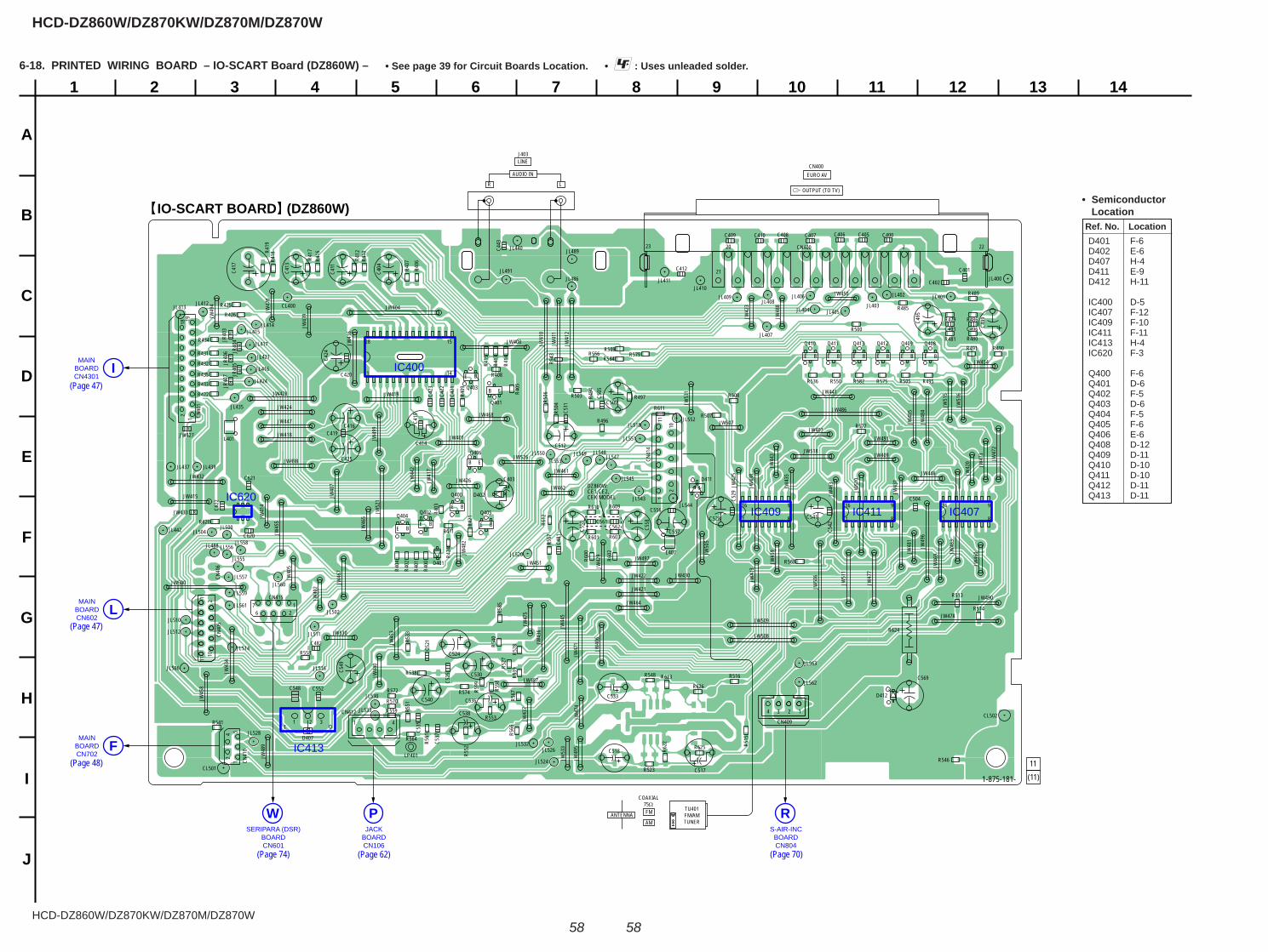
HCD-DZ860W/DZ870KW/DZ870M/DZ870W
HCD-DZ860W/DZ870KW/DZ870M/DZ870W
5858
1
A
B
C
D
E
F
G
H
I
J
2 3 4 5 6 7 8 9 10 11 12 13 14
IO-SCART BOARD (DZ860W)
11(11)1-875-181-
MAINBOARDCN4301
I
MAINBOARDCN602
L
MAINBOARDCN702
F
JACKBOARDCN106
PS-AIR-INC
BOARDCN804
RSERIPARA (DSR)
BOARDCN601
W
IC400
IC409 IC411 IC407IC620
IC413
21 1
20 2 22
I O
B E
B E
BE
1 8
916
1 8
916
1 8
916
JR
JR
15
14
28
1
JR
JR
JR
JR
JR
R400
R401
R402
R403
R404
R405
R406
R407
R408
R409
R600
R601
R602
R603
R410
R411
R412
R413
R414
R415
R609
R416
R417
R418R4
19
R610
CN400
CN40
11
218 19
R611
R612
R421
CN40
5CN
406
R422
R424
CN409
R425
R426
R620
CN41
0
LP401
R622
CN412
R623
R624
CN41
4
R625
CN415
R431
R626
R432
R433
R434
R435
C400
C401
C402
C403
C404
C405C406
CN400
C407C408C409 C410
C411 C412C413
C414
C415
C416
C417
C419
JL400
JL401JL402
JL403
EURO AV
OUTPUT (TO TV)
C420
JL404
CL501
C421
JL405
CL502
C422
JL406
C423
JL407
C424
JL408
C425
JL409
C620
JL410
C621
JL411
C622
JL412JL413
JL414JL415
JL416
JL417
R479
JL421
JL424
C443
R480R481
R485
R486
R489
JL435
JL437
R490
JW401
R491
JL439
JW403
JW404
R494
JW40
5
R495
JW40
6
R496 111
102
JW40
7
R497
JW408
JL440
JW409
JL442
D401
D402
JW41
0
JW41
1
JW41
2
JW41
3
D407
JW41
4
JW415
JW41
6
JR40
3
JW41
7
JR40
4
JW418
JR40
5
JW419
JR40
6JR
407
D411
D412
JW42
0
JW421
JW422
JW42
3
JW424
JW42
5
JW426
JW427
JW428
JW42
9
C481
C482
JW430
JW43
1
JW432
JW433
JW43
4
JW43
5
JW43
6
JW43
7
JW43
8
JW43
9
C491
JW44
0
JW441
C495
JW44
2
C496
JW44
3
JW44
5
C499
JW446
JW447
JL486
JW450
JL488
JW451
JL489
JW45
3
JW454
JW45
5
JW45
8
JW45
9
JL491
JW46
0
JW461
JW462
JW46
3
JW464
JW46
5
JW46
7
JW468
JW46
9
JW47
0
R500
JW47
1
JW47
2
JW47
3
R503
JW47
4
R504
JW47
5
R505
R506
JW47
7
R507
JW478
R508
R509
JW48
1
JW48
2
R513
JW48
3
R514
JW48
4
R515
JW48
5
R516
JW486
JW487
JW48
8
JW48
9
JW490
JW491
JW49
2
R523
JW49
4
JW49
5
JW49
6
JW497
R527
JW498
R528
JW49
9
R533
R536
R538 R539
R540
C504
R541
C505
R543
C509
R546
R548
C511
C512
R550
CL400
R551
R552
R553
C517
C518
R556
R557
R558
JL500
R559
JL502
JL504
C521
JL506
C524
R561
C525
R563
R564
C528
C529
R566
R567
JL510
JL511JL512
C530
JL514
JL516
C533R570
JL518C5
35
R572
C536
C537
R574
C538
R575
R577
JL520
R579
C540
JL524
C541
C542
JL526
JL528
R582
R584
C548
1 2 3
R585
C549
JL530
JL532
JL533
C552
JW500
C556
C557C558
Q400
JW50
5
C559
Q401
JW50
6
Q402
JW507
Q403
JW508
R598
Q404
JW509
R599
Q405
Q406
JL543JL544
Q408
C561
JL545
Q409
C562
JL547
JW51
0
JL548
JW51
1
JL549
Q410
C569
JW51
5
Q411
JW51
6
Q412Q413
JW518JL550
JL551L401
JL552
JL553
JL555
JL556
JL557
L407
JL558
JW52
1
JL559
JW526
JL560
JL561
JL562
JL563
JW530
JW53
1
JW53
3
1726
111
210
15
24
1 4
13 24
1
BEBE
BE
BE
23
E B E B E B E B E B E B
TU401FM/AMTUNER
COAXIAL75ΩFMANTENNAAM
J403
R L
AUDIO IN
LINE
DZ860W:CE1,CE2,CEK MODEL
6-18. PRINTED WIRING BOARD – IO-SCART Board (DZ860W) – • : Uses unleaded solder.• See page 39 for Circuit Boards Location.
(Page 62)
(Page 48)
(Page 47)
(Page 47)
Ref. No. Location
• Semiconductor Location
D401 F-6 D402 E-6 D407 H-4 D411 E-9 D412 H-11
IC400 D-5 IC407 F-12 IC409 F-10 IC411 F-11 IC413 H-4 IC620 F-3
Q400 F-6 Q401 D-6 Q402 F-5 Q403 D-6 Q404 F-5 Q405 F-6 Q406 E-6 Q408 D-12 Q409 D-11 Q410 D-10 Q411 D-10 Q412 D-11 Q413 D-11
(Page 70)(Page 74)
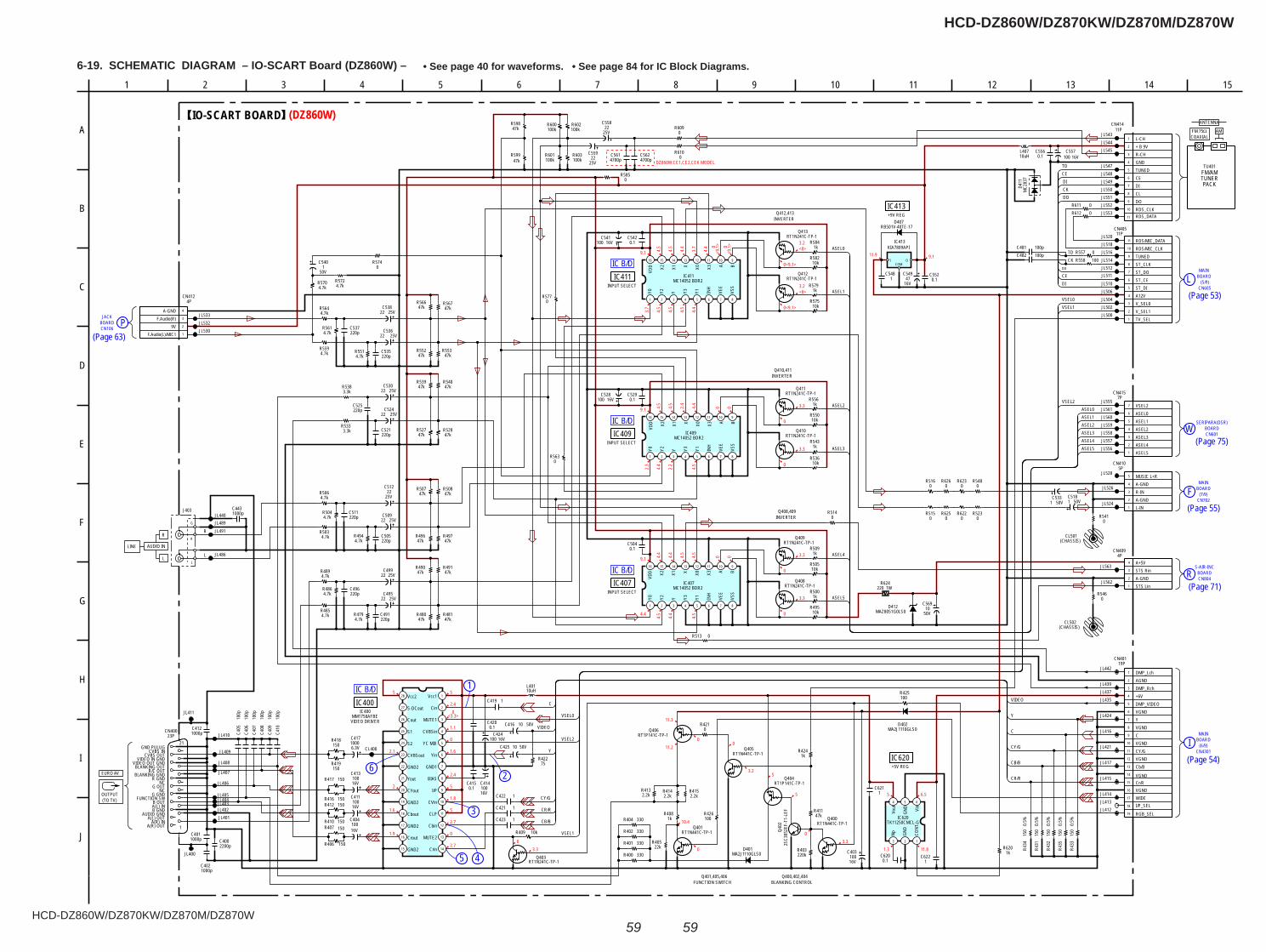
HCD-DZ860W/DZ870KW/DZ870M/DZ870W
HCD-DZ860W/DZ870KW/DZ870M/DZ870W
5959
6-19. SCHEMATIC DIAGRAM – IO-SCART Board (DZ860W) – • See page 40 for waveforms. • See page 84 for IC Block Diagrams.
1
2
3
45
6
BOARDMAIN
(7/9)FCN702
BOARD(5/9)
MAIN
LCN605
BOARD(6/9)
MAIN
ICN4301
BOARDCN106
JACKP
BOARDCN601
WSERIPARA(DSR)
S-AIR-INC
CN804R BOARD
IC B/D
IC B/D
IC B/D
IC B/D
3.3
5
53.2
00
0
11.2
11.3
10.4
03.30
5
2.40
<3.3>
1.1
0
1.6
2.4
5
1.8
5
2.7
0
2.7
1.9
1.6
2
2.1
5
3.2<0>
0<9.1>
3.2<0>
0<9.1>
9.1 4.5
4.5
4.4
3.7
4.4 0
<9.1
> 0<9
.1>
3.7
4.5
4.5
4.5
4.4
9.111.9
5 6.5
11.81.3
(DZ860W)
DZ860W:CE1,CE2,CEK MODEL
04.5
4.4
4.5
9.1 2.4
2.3
04.5
4.4
2.2
0
3.3
0
3.3
4.4
4.4
9.1 4.5
4.4
0
4.54.4
4.5
4.5
0
0
0
3.3
3.3
2.2kR415
50VC425 10
2.2kR414
6.3V1000C417
2.2kR413
1kR408
C4431000p
0.1C420
JL413JL414
50V10C416
RT1P141C-TP-1Q406
1C421
RT1N441C-TP-1Q405
22kR405
R42275
1kR424
JL424
1C423
16V100C414
330R400
330R404
16V100C424
RT1N441C-TP-1Q401
JL415
330R401
0.5%
150
R433
RT1P141C-TP-1Q404
23PCN400
A(R) OUTA(R) IN
A(L) OUTAUDIO GND
B GNDA(L) INB OUT
FUNCTION SWG GND
NCG OUT
NCR GND
BLANKING GNDR/C OUT
BLANKING OUTVIDEO OUT GND
VIDEO IN GNDCVBS OUT
CVBS INGND PULUG CL400
220kR403
10kR409
0.5%
150
R432
RT1N241C-TP-1Q403
330R402
1C422
0.5%
150
R434
C419 1
47kR411
10uHL401
JL412
2SC3
052E
F-T1
-LEF
Q402 0.
5%15
0R4
31
RT1N441C-TP-1Q400
0.1C415
16V100
C403
47kR507
25V22
C559
16V100C541
220pC505
47kR491 10k
R505
47kR552
4.7kR570
RT1N241C-TP-1Q413
4.7kR5514.7k
R559
25V22C499
50V1C518
220pC491
RT1N241C-TP-1Q410
47kR539
4.7kR561
4.7kR564
C5481
C5624700p
4.7kR504
25V22
C512
C5614700p
220pC511
220pC525
0.1C542
10uHL407
47kR496
220pC535
25V22C530
47kR508
16V100C557
47kR599
25V22C509
1kR579
25V22C495
47kR567
10kR495
4.7kR486
47kR527
10kR582
1kR509
50V
C5401
1kR500
1kR584
4.7kR489
47kR566
47kR481
4.7kR494
3.3kR533
R612 0
RT1N241C-TP-1Q408
1kR543
25V22C524
4.7kR485
4.7kR503
50V1C533
0.1C556
RB501V-40TE-17D407
10kR536
47kR528
RT1N241C-TP-1Q411
25V22C536
R5740
100kR603
47kR553
220pC496
0.1C552
10kR550
220pC521
0.1C529
16V100C528
R611 0
16 15 14 13 12 11 10 9
87654321
MC14052 BDR2IC409
Y0 Y2 Y Y3 Y1 INH
VEE
VSS
BAX3X0XX1X2
VDD
4.7kR572
R5630
RT1N241C-TP-1Q409
0.1C504
220pC537
47kR540
1kR556
4.7kR479
4.7kR506
0R609
3.3kR538
16V47
C549
R5770
16 15 14 13 12 11 10 9
87654321
MC14052 BDR2IC407
Y0 Y2 Y Y3 Y1 INH
VEE
VSS
BAX3X0XX1X2
VDD
25V22C538
16 15 14 13 12 11 10 9
87654321
MC14052 BDR2IC411
Y0 Y2 Y Y3 Y1 INH
VEE
VSS
BAX3X0XX1X2
VDD
1
2
3
4
5
6
7
8
9
10
11
11PCN414
L-CH+ B 9VR-CHGNDTUNEDCEDICLDORDS_CLKRDS_DATA
10kR575
25V22
C558
47kR497
47kR490
47kR480
1
2
3
4
4PCN412
F.Audio(L)/MIC19V
F.Audio(R)A-GND
JL440
JL491JL489
JL486
JL530JL532JL533
1000pC412
1000pC401
C4021000p
C4002200p
C409
100p
JL401JL402JL403JL404JL405
JL406
JL407
JL408
JL409
JL410
JL411
JL400
JL417
JL421
JL435JL437JL439
JL442
JL516
JL506
JL520
JL514
JL510
JL502
JL512
JL500
JL504
JL518
JL528
JL526
JL524
JL543JL544JL545
JL547
JL550
JL548JL549
JL552JL551
JL553
150R419
150R418
C410
100p
C408
100p
C407
100p
C406
100p
C405
100p
150R407
150R406
150R410
150R412150R416
150R417
0R610
100kR602
100kR600
100kR601
47kR598
1
2
3
4
5
5PCN410
L-INA-GNDR-INA-GNDMUSIC L+R
I OCOM
KIA7809APIIC413
JL555
JL556JL557JL558JL559JL560JL561
JL562
JL563
123
4 5 6
TK11250CMCL-GIC620
CONT
GND
NpVo
ut
GND Vin
1C621
1C622
R6201k
0.1C620
1
2
3
4
5
6
7
8
9
10
11
11PCN405
TV_SELV_SEL1V_SEL0A12VST_DIST_CEST_DOST_CLKTUNEDRDS/MIC_CLKRDS/MIC_DATA
JL511
J403
IC400MM1758AFBE
Vcc1
Cin
MUTE1
CVBSin
YC MIX
Yin
GND1
BIAS
I/P
CVin
CLP
Cbin
MUTE2
CrinGND2
Crout
GND2
Cbout
GND2
CYout
Yout
GND2
CVBSout
S2
S1
Cout
S-DCout
Vcc2
1
2
3
4
5
6
7
7PCN415
ASEL5ASEL4ASEL3ASEL2ASEL1ASEL0VSEL2
MA2J1110GLS0D401
MA2J1110GLS0D402
1
2
3
4
5
6
7
8
9
10
11
12
13
14
15
16
17
18
19
19PCN401
DMP_LchAGNDDMP_Rch+6VDMP_VIDEOVGNDYVGNDCVGNDCY/GVGNDCb/B
VGNDCr/RVGNDWIDEI/P_SEL
RGB_SEL
0.5%
150
R435
JL416
16V100
C413
16V100
C411
16V100
C404
R5850
0R513
0R514
0R557100R558
C481 100p
CL501(CHASSIS)
MC2
837
D411
100R425
100R426
0R421
CL502(CHASSIS)
R5410
R5460
1
2
3
4
4PCN409
MAZ8051G0LS0D412
50V
C56910
1WR624
220
RT1N241C-TP-1Q412
0R622
0R625
0R626
R5230
R54800
R5160
R623
0R515
C482 100p
DO
ASEL0
ASEL1
ASEL2
ASEL3
ASEL4
ASEL5
VSEL0VSEL1
ASEL5ASEL4ASEL3ASEL2ASEL1ASEL0
DICEDO
VSEL0
VSEL2
TD
TD
CEDICK
VIDEO
Y
C
CY/G
CB/B
CY/G
CR/R
CB/B
VIDEO
VSEL1
VSEL2
CR/R
Y
C
CK
R
L
INPUT SELECTIC407
INPUT SELECTIC409
INPUT SELECTIC411
+9V REGIC413
IC400
VIDEO DRIVER
IC620+5V REG
IO-SCART BOARDFM 75Ω
PACK
FM/AM
AMCOAXIAL
TUNER
TU401
ANTENNA
OUTPUT(TO TV)
EURO AV
152 126 11
C
14
I
H
G
3
B
E
F
4 7
A
91 105
J
D
8 13
Q401,405,406FUNCTION SWITCH
Q400,402,404BLANKING CONTROL
INVERTERQ408,409
INVERTERQ410,411
INVERTERQ412,413
LINE AUDIO IN
R
L
1
21
A+5VSTS RinA-GNDSTS Lin
28
27
26
25
24
23
22 7
6
5
4
3
2
1
21
20
16
17
18
19
13
12
11
10
8
9
15 14
L
R
G
(Page 63)
(Page 53)
(Page 75)
(Page 55)
(Page 71)
(Page 54)
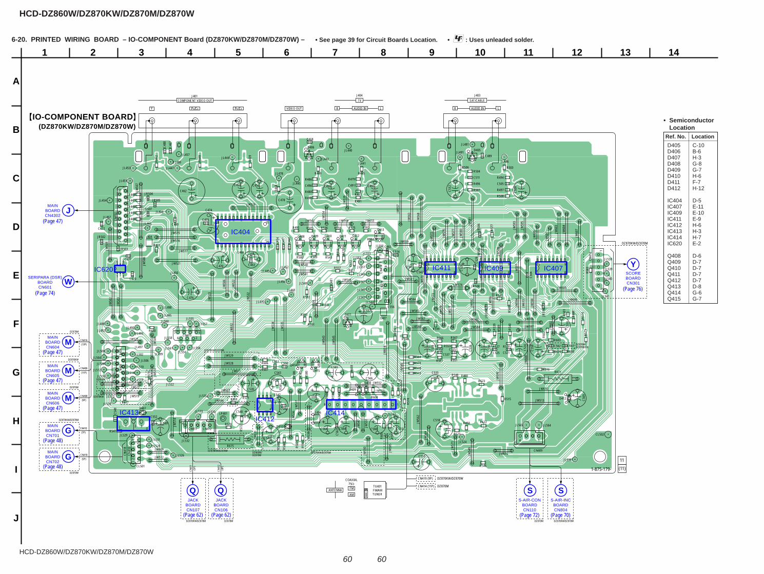
HCD-DZ860W/DZ870KW/DZ870M/DZ870W
HCD-DZ860W/DZ870KW/DZ870M/DZ870W
6060
1
A
B
C
D
E
F
G
H
I
J
2 3 4 5 6 7 8 9 10 11 12 13 14
IO-COMPONENT BOARD(DZ870KW/DZ870M/DZ870W)
1-875-179-
11(11)
DZ870KW/DZ870M
CN419 (9P) DZ870KW/DZ870W
CN414 (11P) DZ870M
DZ870M
DZ870KW
DZ870KW
DZ870W
DZ870W
DZ870KW/DZ870M
DZ870KW/DZ870M
DZ870KW/DZ870M DZ870KW/DZ870M
DZ870KW/DZ870M
DZ860W/DZ870W
DZ870W
DZ870W DZ870KW/DZ870WDZ870M
DZ870M/DZ870W:KR
JACKBOARDCN107
QJACK
BOARDCN106
QS-AIR-CON
BOARDCN110
SS-AIR-INC
BOARDCN804
S
MAINBOARDCN702
G
MAINBOARDCN604
M
MAINBOARDCN605
M
MAINBOARDCN606
M
SERIPARA (DSR)BOARDCN601
W
MAINBOARDCN4302
J
MAINBOARDCN701
G
SCOREBOARDCN301
Y
IC413IC412
IC414
IC620
IC404
IC411 IC409 IC407
145
9 1
I O
1 8
916
15
14
28
1 B E
1 8
916
B E
1 8
916
B E
BE
B E
1 4
58
B EB E
BE
JR
JR
JR
JR
JR
JRJR
JR JR
JW564
JW565
JW566
JW567
JW56
8
JW56
9JW
570
R600
JW57
1
R601
JW57
2
R602
JW57
3
R603
JW574
R604
JW57
5
R605
JW57
6
R606
JW57
7
R607
JW57
8
R608
R609
JW58
0
R610
JW58
1
R611
CN40
2
117
216
JW58
2
R612
JW583
R613
JW584
R614
JW58
5
JW58
6
CN40
6
R616
R617
JW58
8
CN409
JW58
9JW
590
R620
CN41
0
75
16
2
R621
LP401
JW59
1
CN411
R622
CN412
R623
JW59
3
CN41
3 16
JW59
4
CN41
410
82
119
1
CN4151
267
JW59
5
JW596
CN41
6
JW597
CN40
8
JW59
8
CN41
8
CN41
9
R439
R444
R445
R446
R447
R448R4
49
R452
R458
CL501
CL502
C620R4
68
C621
1 3
46
C622
R473
R479
R480
R485
R486
R489
R490
C454
C514
C456
C457
R494
C458
R495
R496
R497
JL440
JL441JL442
JW60
0
C460
JL444
JW60
1
JL445
JW60
2
C462
JW60
3
C463
JL447
JW60
4
JW605
JL449
D405D406
JW606
C466
JW60
7
C467
D407
JW60
8
C468
D408
JW609
D409
JL450
JL451
Y
COMPONENT VIDEO OUT TV SAT/CABLE
PB/CB PR/CR
JL452
JL453
JW610
C470
JL454
JW611
D411
JW61
2
D412
JL456
JW61
3
C473
JL457
JW61
4
C474
JW615
C476
C478
JL460
C480
C481
C482
JL466
JL467
JL468
C488
C489
JL470
C491
JL478
C495C496 C499
JL480
JL481
JL486
JL488JL490
JL491
J401
VIDEO OUT R LAUDIO IN R L
J404 J403
JL492JL493
JL497
JL499
R500
R503R504
R505
R506
R507
R508
R509
R513
R514
R515
R516
R523
R527 R528
R530
R533
R536
R538
R539
R540
C504
R5411 2 3
C505
R543
C509
R546
R548
C511
C512
R550
R551
R552R553
C518
R556
R557
R558
R591
R593
R592
JL500
R559
JL502JL504
C521
JL506
C524
JL508R561
C525
R563
R564
C528
C529
R566 R567
JL510
R569
JL512
C530
JL514JL516
C533
R570
JL518
R571
C535
R572
C536
C537
R574
C538
R575
C539
R577
JL520
R579
JL522
JL523
C540
JL524
C541C542
JL526
C543
R580
JL528
R581
JL529
R582
C546
R583
C547
R584
C548
R585
C549
R586
R587
R588
JL530
R589
JL531 JL532
JL533
C550C551
JL535
C552
JL536C553
JL538
R590
C554
JW50
1
C555
JL539
JW50
2
C556
R595
JW50
3
C557JW
504
R594
C558
JW50
5
C559
JW50
6
R596
JW50
7
R597
JW50
8
R598
JL540
JW50
9
R599
JL541
JL542
C560
JL544
Q408
C561
Q409
C562
C563
JW51
0
C564
JL548
JW511
C565
JW512
C566
JW513
C567
JW51
4
C568
TU401FM/AMTUNER
COAXIAL75ΩFMANTENNAAM
Q410
C569
JW515Q411
JW516JR502 Q412
JW517JR503
Q413
JR504
JL550
Q414
JW519
JR505
Q415
JR50
6
JL552
JR507
JL553
JR508
JL554
L404
JL555
JL556
L406
JL557
L407
JL558
JW521
JW52
2
JW52
3
JW525
JW526
JW527
JW528
JL560
JW529
JR51
5
JL561
JR51
6
JL564
14
JL565
JW53
2
JW53
4
JW53
5
JW53
6JW
537
JW53
8
JW53
9
JW540
JW541
JW542
JW54
3
JW544
JW54
5
JW546
JW54
7
JW548
JW54
9
JW55
0JW
551
JW552
JW553
JW55
4
JW555
JW55
7
JW559
JW56
0
JW561
JW56
2
JW56
3
R459
JL495
JL498
R481
R491
JL543
JL545
JL547
JL549
JL551
D410
C544JW53
1
R615
AUDIO IN
CN416(13P)
CN406(11P)
CN408(9P)
CN410(7P)
CN418(5P)
CN41
1(5
P)
CN41
2(4
P)
6-20. PRINTED WIRING BOARD – IO-COMPONENT Board (DZ870KW/DZ870M/DZ870W) – • : Uses unleaded solder.• See page 39 for Circuit Boards Location.
(Page 62)
(Page 48)
(Page 47)
(Page 47)
Ref. No. Location
• Semiconductor Location
D405 C-10 D406 B-6 D407 H-3 D408 G-8 D409 G-7 D410 H-6 D411 F-7 D412 H-12
IC404 D-5 IC407 E-11 IC409 E-10 IC411 E-9 IC412 H-6 IC413 H-3 IC414 H-7 IC620 E-2
Q408 D-6 Q409 D-7 Q410 D-7 Q411 D-7 Q412 D-7 Q413 D-8 Q414 G-6 Q415 G-7
(Page 72)
(Page 74)
(Page 47)
(Page 47)
(Page 48)
(Page 62) (Page 70)
(Page 76)
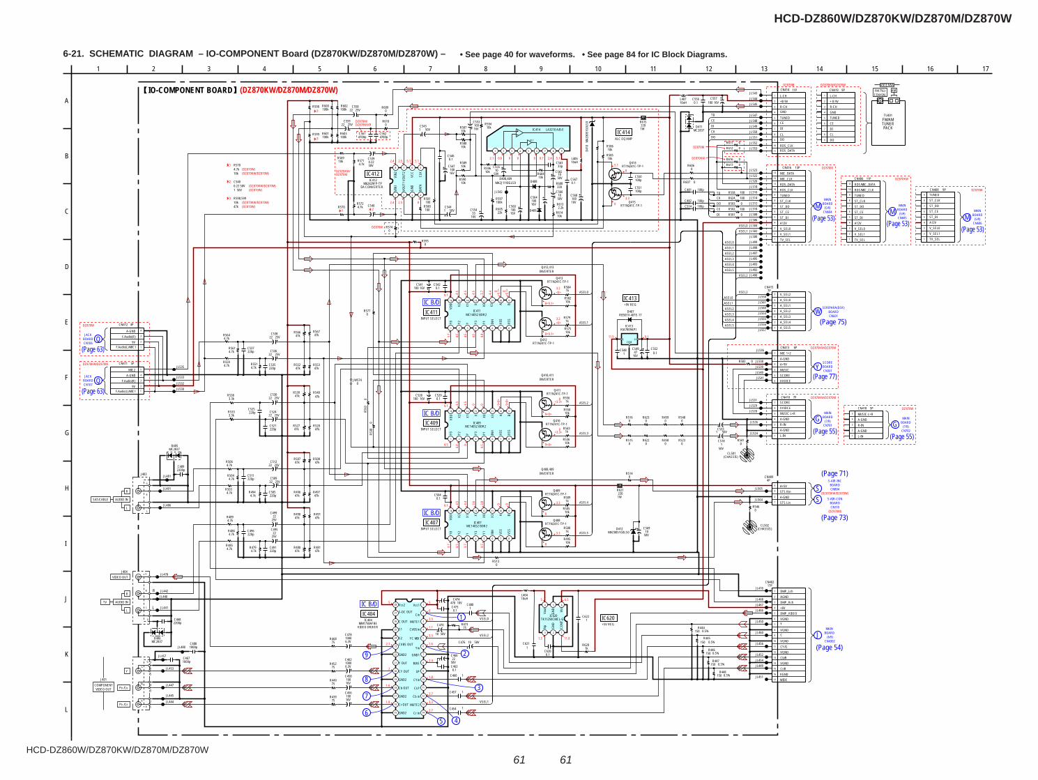
HCD-DZ860W/DZ870KW/DZ870M/DZ870W
HCD-DZ860W/DZ870KW/DZ870M/DZ870W
6161
6-21. SCHEMATIC DIAGRAM – IO-COMPONENT Board (DZ870KW/DZ870M/DZ870W) – • See page 40 for waveforms. • See page 84 for IC Block Diagrams.
(7/9)
MAINBOARDGCN702
CN4302
BOARDMAIN
J (6/9)
BOARDJACK
QCN107
8
7
6
BOARDCN106
QJACK
MAINBOARD
CN604M (5/9)
MAIN
(5/9)CN605
BOARDM(5/9)
CN606M
MAINBOARD
BOARDWCN601
SERIPARA(DSR)
YSCORE
CN301BOARD
G BOARDMAIN
(7/9)CN701
S BOARDS-AIR-INC
CN804
SCN110BOARD
S-AIR-CON
9
5 4
2
1
3
IC B/D
IC B/D
IC B/D
IC B/D
3.3
2.7
2.1
2.7
1.1
2.4
1.6
3.3
0
1.6
3.3
1.9
1.8
5
2
5
4.5
3.7
0
4.5
9.1
4.5
4.4
4.5
4.5
4.4
<9.1
>
4.5
3.7
<9.1
>0
3.2
<0>
0<9.1>
<0>
3.2
0<9.1>
5
11.81.3
6.5
9.111.9
(DZ870KW/DZ870M/DZ870W)
DZ870W
DZ870KW/DZ870M
DZ870M/DZ870W:KR
3
3
(DZ870W)(DZ870KW/DZ870M)
1
2
2.5
2.4 2.5 5.1
2.4
5.1
0
00 2.40.62.1 0 5.10.7
1
2
(DZ870W)(DZ870KW/DZ870M)
3
(DZ870W)(DZ870KW/DZ870M)
DZ870W
3.30
5.10DZ870KW/
DZ870M
DZ870M DZ870KW/DZ870W
DZ870M
DZ870KW
DZ870W
DZ870KW/DZ870M
DZ870KW/DZ870M
DZ870W
(DZ870KW/DZ870W)
(DZ870M)
9.1 0 9<0>
4.5
0 9<0>
4.5
4.44.5 0
4.5
0
9<0>
<3.3>
<3.3>
9<0>
0
9.1 0
3.7
4.5
3.8
4.4
3.6
3.7
4.5
4.5
0
0
3.3
0
3.3
DZ870M
DZ870KW
JL457
R599
R598
6.3V1000C462
75R439
75R449
75R452
L40410uH
16V100
C456
16V100
C458
50V10
C470
0.1C463
0.1C473
10V470C474
C4881000p
0.5%150R445
0.5%150R448
0.5%150R447
50V10C476
R47375
JL478
JL480
1C457
1C454
1C460
IC404MM1758AFBE
Vcc1
Cin
MUTE1
CVBSin
YC MIX
Yin
GND1
BIAS
I/P
CYin
CLP
Cb in
MUTE2
Cr inGND2
Cr OUT
GND2
Cb OUT
GND2
CY OUT
Y OUT
GND2
CVBS OUT
S2
S1
C OUT
S-DC OUT
Vcc2
50V22
C466 0.5%150R446
R583 0
47kR507
25V22C559
RT1N241C-TP-1Q415
16V100C541
220pC505
1 2 9876543
IC414 LA3210 A/B-E
47kR491 10k
R505
47kR552
R570
RT1N241C-TP-1Q413
4.7kR5514.7k
R559
25V22
C499
16V100
C568
C550100p
C551100p
50V1
C518
220pC491
RT1N241C-TP-1Q410
10kR585
47kR539
4.7kR561
4.7kR564
50VC5441
C5481
C5624700p
33pC563
4.7kR504
25V22C512
C5614700p
220pC511
220pC525
1
2
3
4
5
6
7
7PCN410
L-INA-GNDR-INA-GNDMUSIC L+RXVIOCESCORE
RT1N241C-TP-1Q412
0.1C542
10kR586
10uHL407
47kR496
220pC535
25V22C530
10kR614
47kR508
16V100C557
25V22C509
1kR579
2.2kR613
50V10
C555
25V22
C495
10kR588
47kR567
22kR605
10kR495
4.7kR486
47kR527
10kR582
1kR509
10kR590
50V10
C566
C540
R607 0
1kR500
330R60850V10
C565
1kR584
4.7kR489
47kR566
47kR481
4.7kR494
3.3kR533
R612 0
RT1N241C-TP-1Q408
1kR543
4.7kR571
25V22C524
4.7kR485
4.7kR503
50V1C533
0.1C556
RB501V-40TE-17D407
R530
0
10kR536
47kR528
RT1N241C-TP-1Q414
RT1N241C-TP-1Q411
10kR569
5PCN411
F.Audio(L)/MIC19V
F.Audio(R)A-GND
MIC2
25V22C536
R5740
100kR603
47kR553
8 7 6 5
4321
M62429FP-TPIC412
VIN1
VOUT
1
GND
DATA
CLK
VCC
VOUT
2
VIN2
220pC496
16V100
C547
0.1C552
R59610k
10kR587
10kR550
10kR589
220pC521
C5290.1
R6060
R6152201W
16VC528
100
100kR597
R611 0
16 15 14 13 12 11 10 9
87654321
MC14052 BDR2IC409
Y0 Y2 Y Y3 Y1 INH
VEE
VSS
BAX3X0XX1X2
VDD
4.7kR572
R563
0
RT1N241C-TP-1Q409
0.1C504
16V33
C554
220pC537
50V1C543
16V100
C553
47kR540
1kR556
R580100
16V100
C560
4.7kR479
4.7kR506
0R609
R581100
3.3kR538
0.1C567
16V47
C549
R5770
10kR594
16 15 14 13 12 11 10 9
87654321
MC14052 BDR2IC407
Y0 Y2 Y Y3 Y1 INH
VEE
VSS
BAX3X0XX1X2
VDD
25V22C538
16 15 14 13 12 11 10 9
87654321
MC14052 BDR2IC411
Y0 Y2 Y Y3 Y1 INH
VEE
VSS
BAX3X0XX1X2
VDD
1
2
3
4
5
6
7
8
9
10
11
11PCN414
L-CH+B 9VR-CHGND
TUNEDCEDI
CLDO
RDS_CLKRDS_DATA
10kR575
25V22C558
10kR604
47kR497
0.1C546
47kR490
16V100
C564
50V0.22C539
47kR480
4PCN412
F.Audio(L)/MIC19V
F.Audio(R)A-GND
C4892200p
75R468
6.3V1000C478
1000pC467
JL447
JL445
JL444
JL453
JL491
JL486
JL481
JL530JL532
JL533
JL535
JL542
JL460
JL456
JL454JL452
JL451
JL449
JL466
JL468
JL470
JL490
JL497
JL499
JL493JL492
JL495
JL498
JL516
JL522
JL506
JL520
JL514
JL510
JL502
JL512
JL500
JL518
JL508
JL523
JL531JL529JL528
JL526
JL524
JL536
JL538JL539JL540JL541
JL543JL544JL545
JL547
JL550
JL548JL549
JL552JL551
JL553
0R610
100kR602
100kR600
100kR601
JL440
JL441
JL442
R
G
J401
12
34
567
1
2
3
4
5
6
6PCN413
MIC 1+2A-GNDA+9VMUSICSCOREXVOICE
I OCOM
KIA7809APIIC413
MC2837D405
JL504
JL554JL555JL556JL557
JL558
JL560JL561
10uHL406 R616 0
R617 0
JL564
JL565
1
2
3
4
5
5PCN418
L-INA-GNDR-INA-GNDMUSIC L+R
1
2
3
4
5
6
7
8
9
9PCN419
L-CH+ B 9VR-CHGNDTUNEDCEDICLDO
1
2
3
4
5
6
7
8
9
10
11
11PCN406
TV_SELV_SEL1V_SEL0A12VST_DIST_CEST_DOST_CLKTUNEDRDS/MIC_CLKRDS/MIC_DATA
1
2
3
4
5
6
7
8
9
10
11
12
13
13PCN416
TV_SELV_SEL1V_SEL0A12VST_DIST_CEST_DOST_CLKTUNEDRDS_CLKRDS_DATAMIC_CLKMIC_DATA
123
4 5 6
TK11250CMCL-GIC620
CONT
GND
NpVo
ut
GND Vin
1C621 R620
1k
1C622
0.1C620
JL467
D408
D409
R
V
L
G
J404
2200pC468
L
R
G
J403
MC2837D406
1
2
3
4
5
6
77P
CN415
A_SEL5A_SEL4A_SEL3A_SEL2A_SEL1A_SEL0V_SEL2
1
2
3
4
5
6
7
8
9
10
11
12
13
14
15
16
17
17PCN402
DMP_LchAGNDDMP_Rch+6VDMP_VIDEOVGNDY
VGNDC
VGNDCY/GVGNDCb/BVGNDCr/RVGNDWIDE
0.5%150R444
JL450
1C480
MAZ
8051
G0LS
0D4
10
R5950
0R513
0R514
100R624100R558
C481 100p
CL501(CHASSIS)
R5410
MC2837D411
CL502(CHASSIS)
R5460
1
2
3
4
4PCN409
JW5740
MAZ8051G0LS0D412
50V
C56910
R6212201W
R5230
0R516
R6220
R5480
R4580
R4590
R6230
0R515
0R593
0R591100R592
C482 100pC514 100p
1
2
3
4
5
6
7
8
9
9PCN408
TV_SELV_SEL1V_SEL0A12VST_DIST_CEST_DOST_CLKTUNED
ASEL0
ASEL1
ASEL2
ASEL3
ASEL4
ASEL5
ASEL5ASEL4ASEL3ASEL2
ASEL1ASEL0
ASEL0ASEL1
ASEL4
VSEL2ASEL5
ASEL3ASEL2
VSEL1VSEL0
DI
VSEL2
CK
TDCEDICKDO
TD
VSEL1
VSEL0
VSEL2
DOCE
Y
ALC
G
BL
R
R
L
IO-COMPONENT BOARD
IC404
VIDEO DRIVER
INPUT SELECTIC407
IC409INPUT SELECT
IC411INPUT SELECT
IC412
DA CONVERTER
ALC EQ AMP
IC414
+5V REGIC620
IC413+9V REG
PACKTUNER
AM
FM/AM
ANTENNA
TU401
R
L
VIDEO OUT
R
L
AUDIO IN
COMPONENTVIDEO OUT
Y
PR /CR
PB /CB
152 12 166 11
C
L
14
I
H
K
G
3
B
E
17
F
4 7
A
91 105
J
D
8 13
TV
Q408,409INVERTER
Q410,411INVERTER
Q412,413INVERTER
SAT/CABLE AUDIO IN
10k
R5704.7k
1 50V
C5400.22 50V
47k
R598,59910k
D408,409MA2J1110GLS0
A+5VSTS RinA-GNDSTS Lin
28
27
26
25
24
23
22 7
6
5
4
3
2
1
21
20
16
17
18
19
13
12
11
10
8
9
15 14
FM 75ΩCOAXIAL
1
2
3
4
1
2
3
4
5
(Page 63)
(Page 63)
(Page 53)(Page 53)
(Page 53)
(Page 75)
(Page 77)
(Page 55)(Page 55)
(Page 71)
(Page 73)
(Page 54)
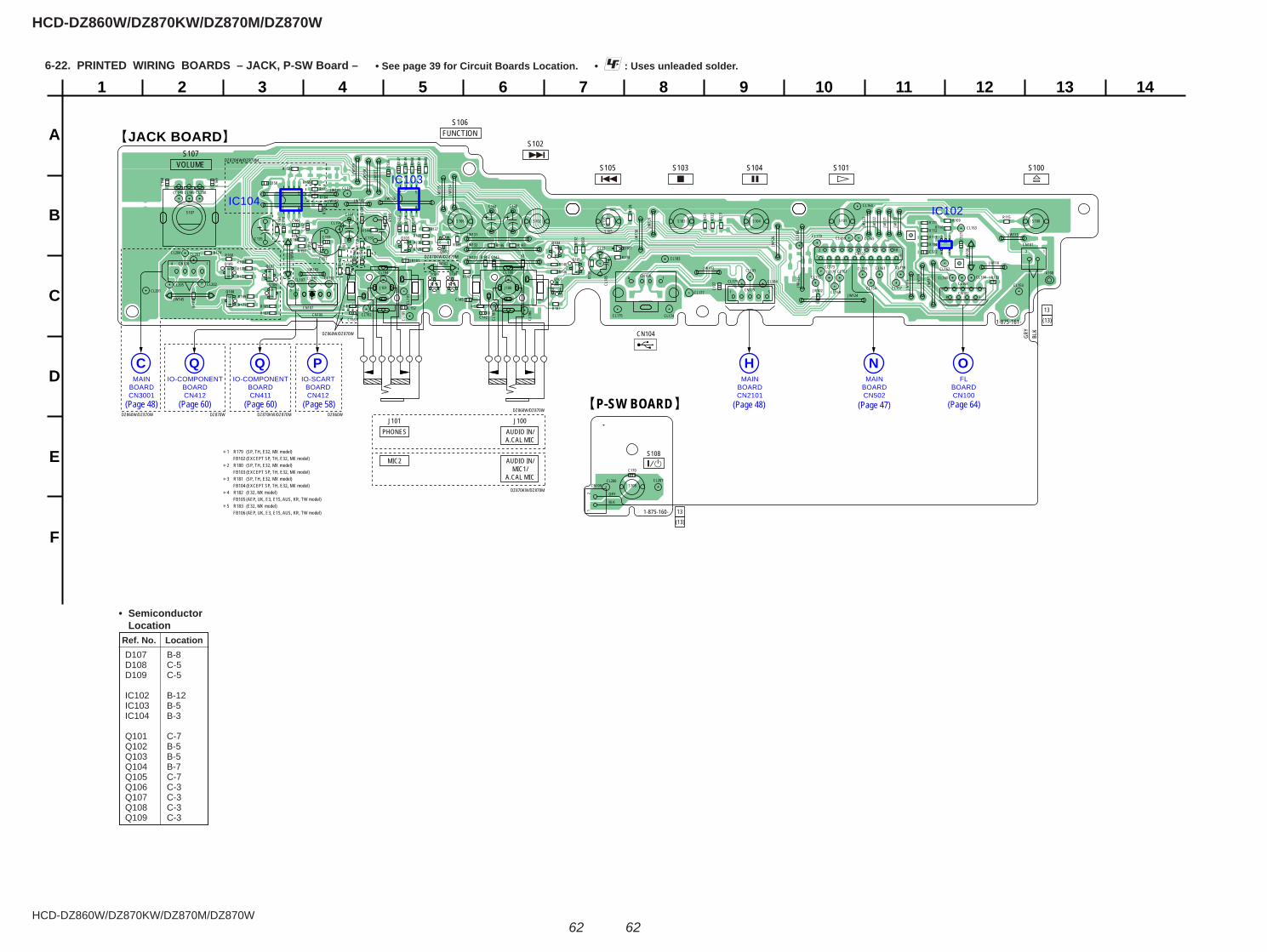
HCD-DZ860W/DZ870KW/DZ870M/DZ870W
HCD-DZ860W/DZ870KW/DZ870M/DZ870W
6262
1
A
B
C
D
E
F
2 3 4 5 6 7 8 9 10 11 12 13 14
P-SW BOARD
JACK BOARD
DZ870KW/DZ870M
DZ860W/DZ870W
DZ870KW/DZ870M
DZ870KW/DZ870M
DZ860W/DZ870W DZ860WDZ870W
1-875-161-
13
(13)
13
(13)
DZ860W/DZ870W
DZ870KW/DZ870M
IO-SCARTBOARDCN412
PMAIN
BOARDCN2101
HFL
BOARDCN100
OMAIN
BOARDCN502
NIO-COMPONENT
BOARDCN411
QIO-COMPONENT
BOARDCN412
QMAIN
BOARDCN3001
C
IC103
IC102IC104
12
9
28JR
JR
BE
BE
BEB
E
BE
B E
8
1 4
5
BE
8
1 4
5
BE
BE
A100
GRY
BLK
Q101
Q102
Q103Q104
Q105
Q106
Q107
Q108
Q109
CL153CL154
CL155
CL156
CL157CL158
CL159
CL160
CL161 CL162
CL163
CL164
CL165CL166
CL167
CL16
8
CL169
CL170
CL171CL172
CL173
CL174CL175
CL177
CL179
CL181
CL183
CL184
CL18
5
CL18
6
CL18
7
CL188
CL18
9
CL190
CL19
1
CL192
CL193
CL194CL195
CL196
CL197
CL198 CL199
R109R110
R111
R112R113
R114
R115
CN101
CN102
CN103
CN104
CN104
R121
CN105 5
2 181 19
1
R122
CN106
R123
CN107
CN108
R126
R128
R132
R133
R134R1
35
R136
R137
R138
R139
R140
R143
R144
R146
R147
R148
R149
R150
R156
R157 R158 R1
59
CL200
C121
CL201
C122
CL202
CL203
R160
CL204
S100
R161
CL205
S101
R162
S102
S102
S106FUNCTION
J101PHONES
J100AUDIO IN/A.CAL MIC
MIC2 AUDIO IN/MIC1/
A.CAL MIC
S107VOLUME S103 S104 S101 S100
R163
C127
S103
R164
S104
R165
S105
S106
R167
S107
R168
1
4 15
4
C132
C133
C134
C135
C136
R173
C137
R174
C138
C139
C142
C144
C145
C147
R184
C148
R186
R187C152
JW10
0
C156
JW102JW103
C157
C158
C159
C160 C161
C162
C164
C166
D107
C168
D108
JR101
JW115
C169
D109
JR102
JW116
JR103
JW11
7
JW11
8
JW11
9
JW12
0
JW12
1
JW12
2
JW12
3
JW124
JW12
5
JW12
6
JW12
9
JW13
0
JW13
4
JW13
5
JW136
JW13
7
JW13
8
JW13
9
JW140
JW141
JW142
JW143
JW14
4
JW145
J100J101
12
CN109CL206
GRY
BLK
CL207S108
C170
1
13
54
14
1-875-160-
S105
S108
R141R155
R153
R129R130R131
R166
R169
R170
R171
R172
C165
R145 C143
JW131
JW132
JW133JR
1 R179 (SP, TH, E32, MX model) FB102 (EXCEPT SP, TH, E32, MX model)2 R180 (SP, TH, E32, MX model) FB103 (EXCEPT SP, TH, E32, MX model)3 R181 (SP, TH, E32, MX model) FB104 (EXCEPT SP, TH, E32, MX model)4 R182 (E32, MX model) FB105 (AEP, UK, E3, E15, AUS, KR, TW model)5 R183 (E32, MX model) FB106 (AEP, UK, E3, E15, AUS, KR, TW model)
4
5
3
1
2
6-22. PRINTED WIRING BOARDS – JACK, P-SW Board – • : Uses unleaded solder.• See page 39 for Circuit Boards Location.
(Page 64)(Page 48) (Page 47)(Page 48)(Page 60) (Page 58)
Ref. No. Location
• Semiconductor Location
D107 B-8 D108 C-5 D109 C-5
IC102 B-12 IC103 B-5 IC104 B-3
Q101 C-7 Q102 B-5 Q103 B-5 Q104 B-7 Q105 C-7 Q106 C-3 Q107 C-3 Q108 C-3 Q109 C-3
(Page 60)
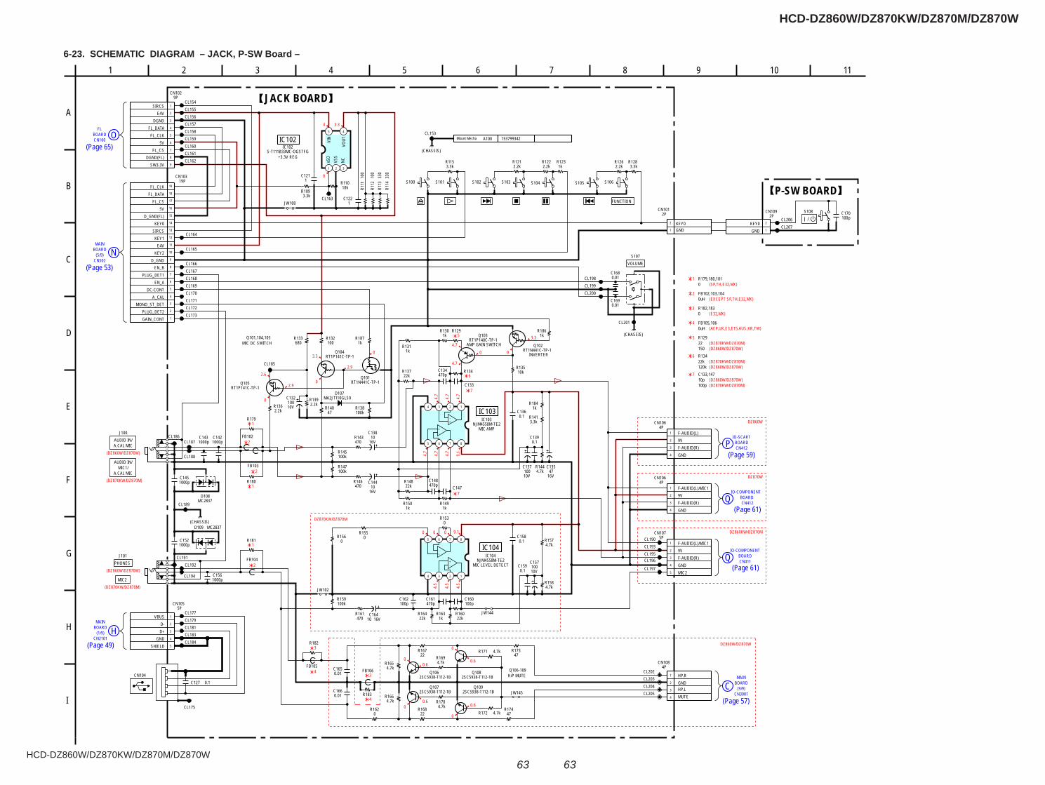
HCD-DZ860W/DZ870KW/DZ870M/DZ870W
HCD-DZ860W/DZ870KW/DZ870M/DZ870W
6363
6-23. SCHEMATIC DIAGRAM – JACK, P-SW Board –
OFL
BOARDCN100
HMAIN
BOARD(1/9)
NMAIN
BOARD(5/9)
CN2101
CN502
BOARDIO-COMPONENT
CN412Q
BOARDIO-COMPONENT
CN411Q
MAIN
(9/9)C BOARD
CN3001
BOARDIO-SCART
CN412P
4 3.3
0
2.6
0
3.3
0
0
2.9
0
3.3
04.7
4.7
4.7
4.7
4.7
4.7
4.7
4.7
9.1
0
4.5
4.5
4.5
0.6
0.60.6
0.6
0
0
0
0
2.9
DZ860KW/DZ870M
DZ870W(DZ870KW/DZ870M)
5
6
7
7
1
2
2
1
1
2
3
4
3
4
(SP,TH,E32,MX)1
(DZ860W/DZ870W)
(DZ870KW/DZ870M)
(DZ860W/DZ870W)
(DZ870KW/DZ870M)(DZ860W/DZ870W)
5
2(EXCEPT SP,TH,E32,MX)
(E32,MX)3
(AEP,UK,E3,E15,AUS,KR,TW)4
6
(DZ860W/DZ870W)(DZ870KW/DZ870M)
7(DZ860W/DZ870W)(DZ870KW/DZ870M)
0 0 9.1
DZ870KW/DZ870M
DZ860W/DZ870W
DZ860W
C145
16V10
C138
16V10
C14416V47
C135
10V100
C137
470pC148
470pC134
C133
C1471000p
0.1C139
0.1C158
470R143
470R146
1kR130
1kR131
1kR150
1kR149
4.7kR144
10kR135
R134
22kR148
22kR137
100kR145
100kR147
0R153
0R155
FB102
FB103
FB104
RT1N441C-TP-1Q102
INVERTER
8765
4 3 2 1
NJM4558M-TE2IC103
8765
4 3 2 1
NJM4558M-TE2IC104
J100
J101
1000pC152
C1660.01
C1650.01
Q103RT1P140C-TP-1
AMP GAIN SWITCH
R1560
100kR159
470R161
16VC164
10R16422k
C161470p
R1631k
C160100p
R16022k
4.7kR158
4.7kR157
3.3kR128
S105
2.2kR126
S106
3.3kR115
S101S100
2.2kR121
S102 S104S103
2.2kR122
1kR123
2PCN101
GNDKEY0
R129
100R132
RT1P141C-TP-1Q104
2.2kR139
RT1P141C-TP-1Q105
2.2kR136 10V
100C132 MA2J1110GLS0
D107
680R133
100kR138
47R140
RT1N441C-TP-1Q101
1
2
3
4
5
CN1075P
F-AUDIO(L)/MIC19VF-AUDIO(R)GNDMIC2
0.01C168
0.01C169
FB105
10V
C157100
1
2
3
4
CN1064P
F-AUDIO(L)/MIC19VF-AUDIO(R)GND
2SC5938-T112-1BQ107
2SC5938-T112-1BQ109
R172 4.7k
R16722
1
2
3
4
4PCN108
HP.RGNDHP.LMUTE
R17347
R17447
2SC5938-T112-1BQ106
R171 4.7k
2SC5938-T112-1BQ108
R1654.7k
R16822
R1664.7k
R1694.7k
R1704.7k
1000pC143
1000pC142
1000pC156
JW102
MC2837D108
MC2837D109
FB106
R1620
0.1C159
C162100p
C127 0.1
10kR110
330
R114
330
R113
JW1003.3k
R109
100
R111
1C122
5 4
321
S-T111B33MC-OGSTFGIC102
xSD
VSS
NCVO
UTVIN
100
R112
1C121
1
2
3
4
5
6
7
8
9
10
11
12
13
14
15
16
17
18
1919P
CN103
GAIN_CONTPLUG_DET2
MONO_ST_DETA_CAL
DC-CONTEN_A
PLUG_DET1EN_B
D_GNDKEY2
E4VKEY1
SIRCSKEY0
D_GND(FL)5V
FL_CSFL_DATAFL_CLK
Mount Mecha 153799342A100
1
2
3
4
5
6
7
8
9
9PCN102
SIRCSE4V
DGNDFL_DATAFL_CLK
5VFL_CS
DGND(FL)SW3.3V
CL173
CL179
CL200
CL204CL203
CL172
CL181
CL169
CL158
CL168
CL171
CL187
CL160
CL167
CL189
CL193
CL157
CL164
CL196
CL162
CL183
CL161
CL194
CL165
CL188
CL184
CL159
CL195
CL192
CL166
CL153
CL186
CL201
CL197
CL190
CL198
CL202
CL185
CL155
CL199
CL191
CL154
CL175
CL163
CL170
CL156
CL177
CL205
C1360.1R179
R180
R181
R182
R183
CN104
1
2
3
4
5
CN1055P
VBUSD-D+
GNDSHIELD
S107
3.3kR141
1kR184
1kR186
1kR187
JW144
JW145
2PCN109
GNDKEY0
100pC170
CL207CL206
S108
(CHASSIS)
(CHASSIS)
(CHASSIS)
1
2
3
4
CN1064P
F-AUDIO(L)9VF-AUDIO(R)GND
+
+-
-
+
+-
-
VOLUME
IC102
+3.3V REG
IC103
MIC AMP
IC104
MIC LEVEL DETECT
JACK BOARD
P-SW BOARDFUNCTION
/
Q101,104,105MIC DC SWITCH
Q106-109H/P MUTE
PHONES
AUDIO IN/A.CAL MIC
8
F
E
G
2
I
H
1075 11
D
A
9
C
4 61 3
B
R179,180,1810
AUDIO IN/MIC1/
A.CAL MIC
MIC2
22R129
150
FB102,103,1040uH
0R182,183
0uHFB105,106
22k120k
R134
10p100p
C133,147
1
2
1
2
(Page 65)
(Page 53)
(Page 49)
(Page 61)
(Page 61)
(Page 57)
(Page 59)

HCD-DZ860W/DZ870KW/DZ870M/DZ870W
HCD-DZ860W/DZ870KW/DZ870M/DZ870W
6464
1
A
B
C
D
E
F
G
H
I
2 3 4 5 6 7 8 9 10 11 12 13 14
M+
-
FL BOARD
SPEAKER BOARD MS-203 BOARD
1-861-327-
(13)13
1-875-159-
12(13)13
1-875-162-
OJACK
BOARDCN102
ZMAIN
BOARDCN1202
AMAIN
BOARDCN3100
BMAIN
BOARDCN3200
AMAIN
BOARDCN3100
IC100
IC101
OVCC 12551 4852
23
33
22
34
12
441
11
CCB BE
CL100
CL101CL102
CL103
CL104
CL105
CL106CL107
CL108
CL109
CL110
CL111
CL112CL113CL114
CL115CL116CL117CL118CL119CL120CL121CL122
CL123
CL124
CL125
CL126
CL127
CL128CL129
CL130
CL131
CL132
CL133
CL134
CL135
CL136
CL138
CL139CL140
CL141
CL143
CL144
Q100
CL145
CL146
CL147CL148
CL149
CL150
CL151
L100L101
ND100FLUORESCENT INDICATOR TUBE
R100
R102
R108
CN100
C101
C102
C103
C108
C116
C117
JW10
4
JW10
5
D103
JW11
0
JW11
1
JW11
2
JW113
JW11
4
IC101
T1001
1
1 9
82
2 3
452
3
4
567
8
9C189
C190
1 8CN114
CN115
CL239
CL240
CL241 CL242
CL243CL244
CL245
CL246
CL247
CL248
CL249
C173
C174
C175
C176
ET102
C177
ET103
C178
C179
C180
C181
EXCEPT SP, TH, E32, MX MODEL
RU MODEL
DZ870M DZ870MDZ860W/DZ870KW/DZ870W
DZ860W/DZ870KW/DZ870W
C182
C183
C184
C185
C186
C187
C188
JW149
JW15
1
(CHASSIS) (CHASSIS)
FRONT R FRONT L SUR R SUR L
SPEAKERTB100
FRONT L FRONT R
SPEAKERTB101
42
51
CN001
S001(CHUCK/TRAY DETECT)
M001(LOADING)
CL137
CL142
R104
R105
R106
R107 CL152
C107
L102
D101
D100
R101
R103
C104
C105
C106
D102
JW106
JW107
EXCEPT SP, TH, E32, MX MODEL
DZ870M
6-24. PRINTED WIRING BOARDS – FL, MS-203, SPEAKER Board – • : Uses unleaded solder.• See page 39 for Circuit Boards Location.
(Page 48) (Page 48)
(Page 62)
(Page 47)
Ref. No. Location
• Semiconductor Location
D100 C-7 D101 C-7 D102 C-7 D103 B-3
IC100 C-5 IC101 B-3
Q100 C-8
(Page 48)
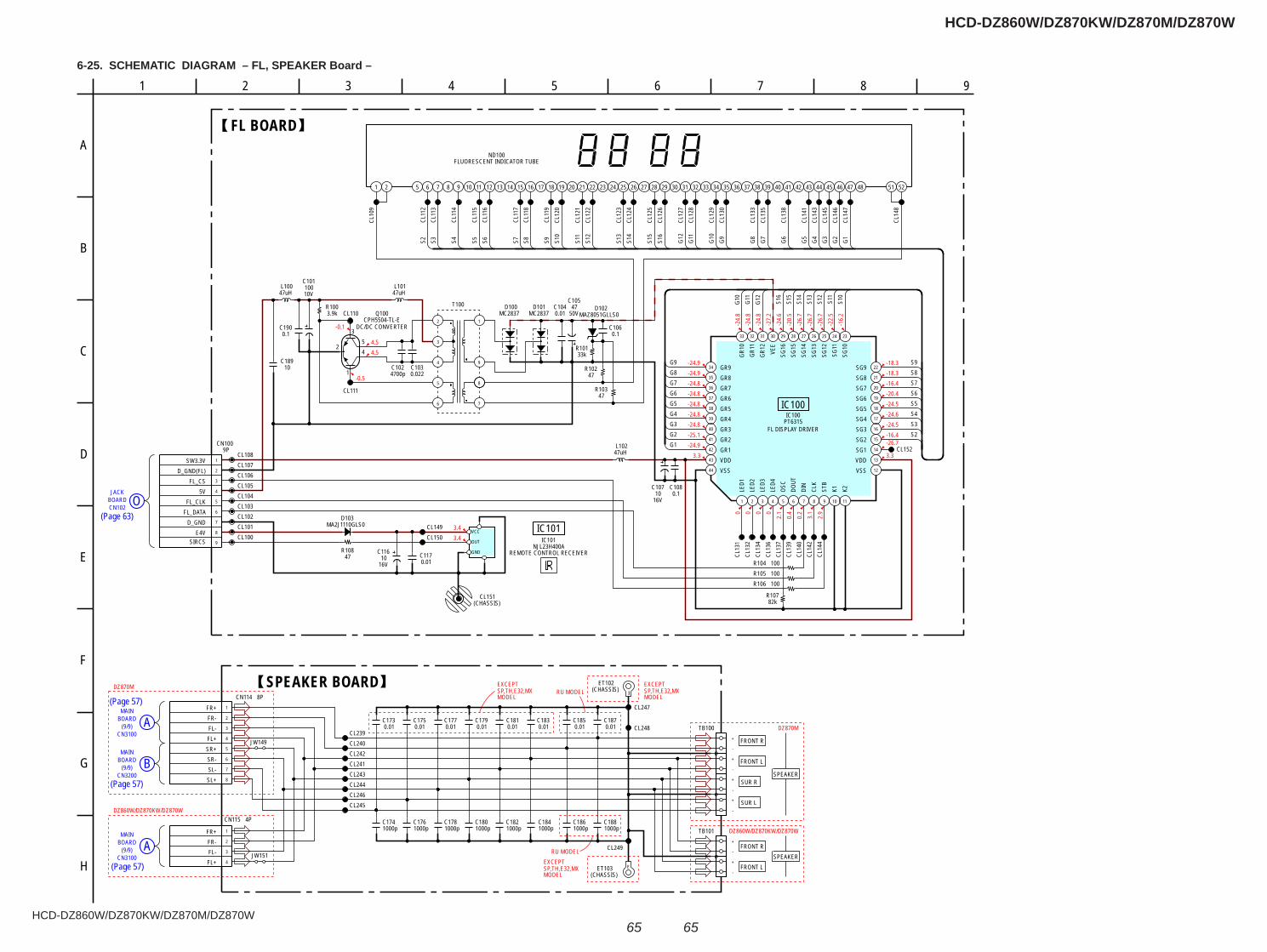
HCD-DZ860W/DZ870KW/DZ870M/DZ870W
HCD-DZ860W/DZ870KW/DZ870M/DZ870W
6565
6-25. SCHEMATIC DIAGRAM – FL, SPEAKER Board –
O
A
B
A
CN3100(9/9)
BOARDMAIN
(9/9)BOARDMAIN
CN3200
BOARD
CN3100(9/9)
MAIN
CN102BOARDJACK
4.54.5
-0.5
-0.1
3.43.4
-24.9-24.9-24.8-24.8-24.8-24.8-24.8-25.1-24.9
3.3
-18.3-18.3-16.4-20.4-24.5-24.6-24.5-16.4-26.7
3.3
-24.
8-2
4.8
-24.
8-2
7.2
-24.
6-2
0.5
-26.
7-2
6.7
-26.
7-2
2.5
-16.
2
0 02.
10.
40.
23.
12.
900
DZ870M
DZ860W/DZ870KW/DZ870W
DZ860W/DZ870KW/DZ870W
DZ870M
EXCEPTSP,TH,E32,MXMODEL
EXCEPTSP,TH,E32,MXMODEL
RU MODEL
RU MODEL
EXCEPTSP,TH,E32,MXMODEL
16V10
C11647
R108
100R106100R105
82kR107
4700pC102
0.022C103
47R103
0.1C106
0.01C104
47uHL100
47uHL101
3.9kR100
47R102
33kR101
D102MAZ8051GLLS0
10V100
C101
0.01C117
MA2J1110GLS0D103
16V10
C107
MC2837D100
MC2837D101
1 2 3 4 5 6 7 8 9 10 11
12
13
14
15
16
17
18
19
20
21
22
2324252627282930313233
34
35
36
37
38
39
40
41
42
43
44
2
3
5
6
8
7
1
4 9
T100
1
2
3
4
5
6
7
8
9
9PCN100
100R104
CL100CL101CL102
CL108CL107CL106CL105CL104CL103
CL110
CL111
CL149CL150
CL151(CHASSIS)
CL152
10C189
VCC
OUT
GND
1 5 6 7 8 9 10 11 12 13 14 15 16 17 18 19 20 21 22 23 24 25 26 27 28 29 30 31 32 33 34 35 36 37 38 39 40 41 42 43 44 45 46 47 48 522 51
50V47
C105
0.1C108
0.1C190
47uHL102
CL246
E
ET102(CHASSIS)
C1881000p
0.01C179
CL240
0.01C173
1
2
3
4
5
6
7
8
8PCN114
CL241
0.01C175
-
+
-
+
-
+
+
-
TB100CL248
CL242
JW149
0.01C177
1000pC174
CL243
CL247
JW151
1000pC176
0.01C185
CL244
1000pC178
+
-
+
-
TB101
EET103(CHASSIS)
CL245
0.01C181
1000pC180
0.01C183
1
2
3
4
CN115 4P
CL239
1000pC182
0.01C187
1000pC184
CL249
1000pC186
G2G3G4G5G6G7G8G9
G1
G4G5G6G7G8G9G10
G11
G12
S16
S15
S14
S13
S12
S11
S10
S9S8S7S6S5S4S3S2 G3 G2 G1
FL BOARD
SPEAKER BOARD
354
1
2
F
1
B
9
G
C
H
2 3
A
5 8
D
E
74 6
SW3.3VD_GND(FL)
FL_CS5V
FL_CLKFL_DATA
D_GNDE4V
SIRCS
FR+FR-FL-FL+SR+SR-SL-SL+
FR+FR-FL-FL+
FRONT R
FRONT L
SUR R
SUR L
FRONT R
FRONT L
VSSVDDSG1SG2SG3SG4SG5SG6SG7SG8SG9
LED1
LED2
LED3
LED4
OSC
DOUT
DIN
CLK
STB
K1 K2
GR9GR8GR7GR6GR5GR4GR3GR2GR1VDDVSS
SG10
SG11
SG12
SG13
SG14
SG15
SG16
VEE
GR12
GR11
GR10
PT6315IC100
FL DISPLAY DRIVER
IC100
NJL23H400AIC101
REMOTE CONTROL RECEIVER
IC101
ND100FLUORESCENT INDICATOR TUBE
SPEAKER
SPEAKER
CPH5504-TL-EQ100
DC/DC CONVERTER
CL13
6CL
134
CL13
7
CL13
1
CL14
0
CL14
4
CL13
9
CL14
2
CL13
2
S10
S12
S13
S11
S14
S15
G10
G11
G12
S16
S9S8S7S6S5S4S3S2
CL10
9
CL14
8
CL11
2CL
113
CL11
4
CL11
5CL
116
CL11
7CL
118
CL11
9CL
120
CL12
1CL
122
CL12
3CL
124
CL12
5CL
126
CL12
7CL
128
CL12
9CL
130
CL13
3CL
135
CL13
8
CL14
1CL
143
CL14
5CL
146
CL14
7
(Page 63)
(Page 57)
(Page 57)
(Page 57)
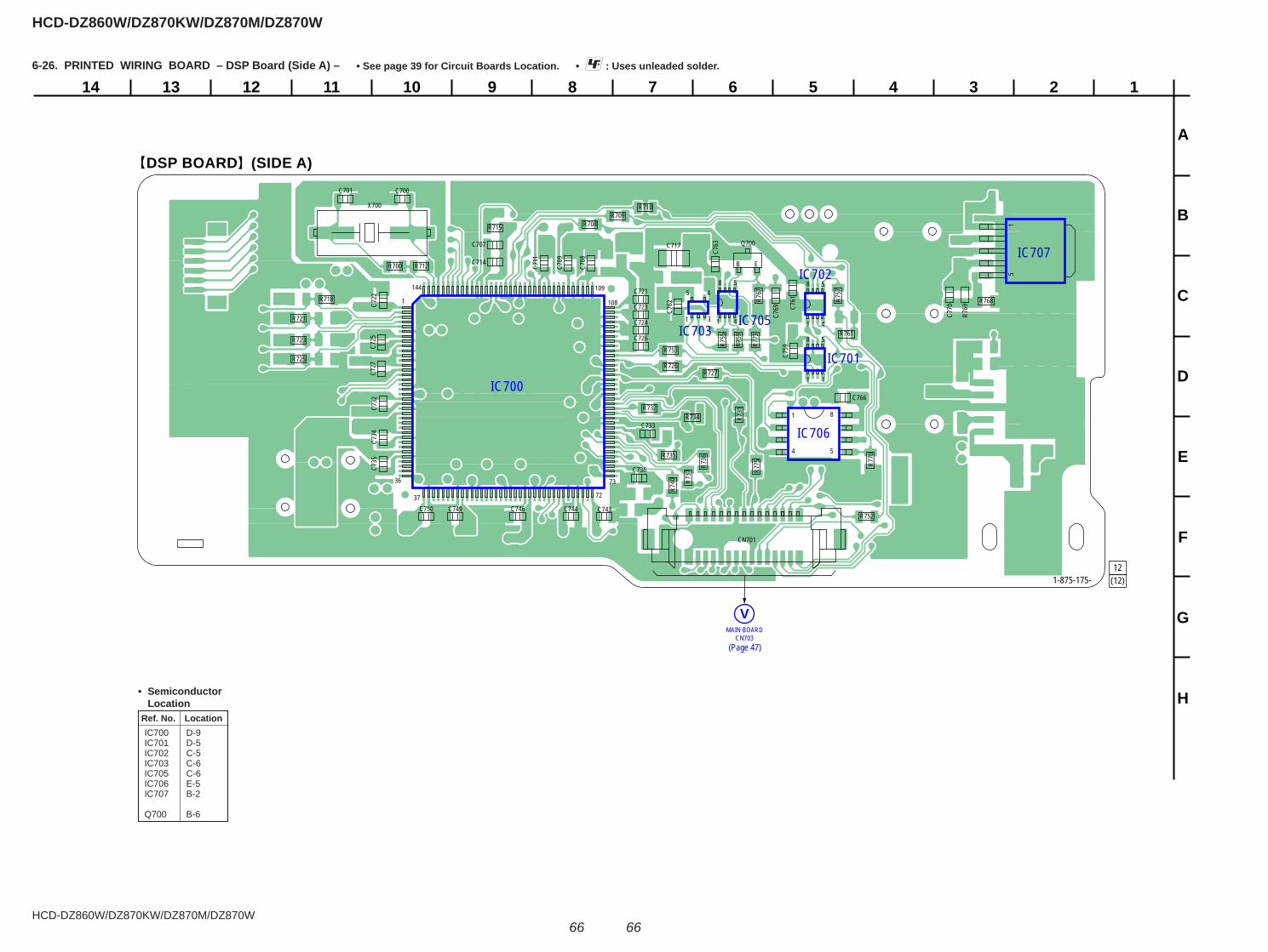
HCD-DZ860W/DZ870KW/DZ870M/DZ870W
HCD-DZ860W/DZ870KW/DZ870M/DZ870W
6666
6-26. PRINTED WIRING BOARD – DSP Board (Side A) – • : Uses unleaded solder.• See page 39 for Circuit Boards Location.
1234567891011121314
A
B
C
D
E
F
G
H
12(12)
DSP BOARD (SIDE A)
MAIN BOARDCN703
V
IC700
IC703IC705
IC702
IC701
IC707
IC706
B E
144
1 108
109
73
72
36
37
15
1
4 5
8
Q700
R700
R708R709
R710
R712
R715
R718
CN701
R721
R723
R725R726
R727
R731R732
R734
R735
R736
R737
C700C701
R740
C707
C708
C709
X700
C711C714
R752
R753
C717
1 1
1 4
8 5
1 4
8 5
4
58
3
45
R755
R757
R759
C721
C722
C723
C724R761
C725 C726
C727
R767
R768
R769
C732
C733
R770
C734
C735
C736
R773
R775
C743C744C746C749C750
C759
C761
C762
C763
C766
C769
C770
1-875-175-
(Page 47)
Ref. No. Location
• Semiconductor Location
IC700 D-9 IC701 D-5 IC702 C-5 IC703 C-6 IC705 C-6 IC706 E-5 IC707 B-2
Q700 B-6
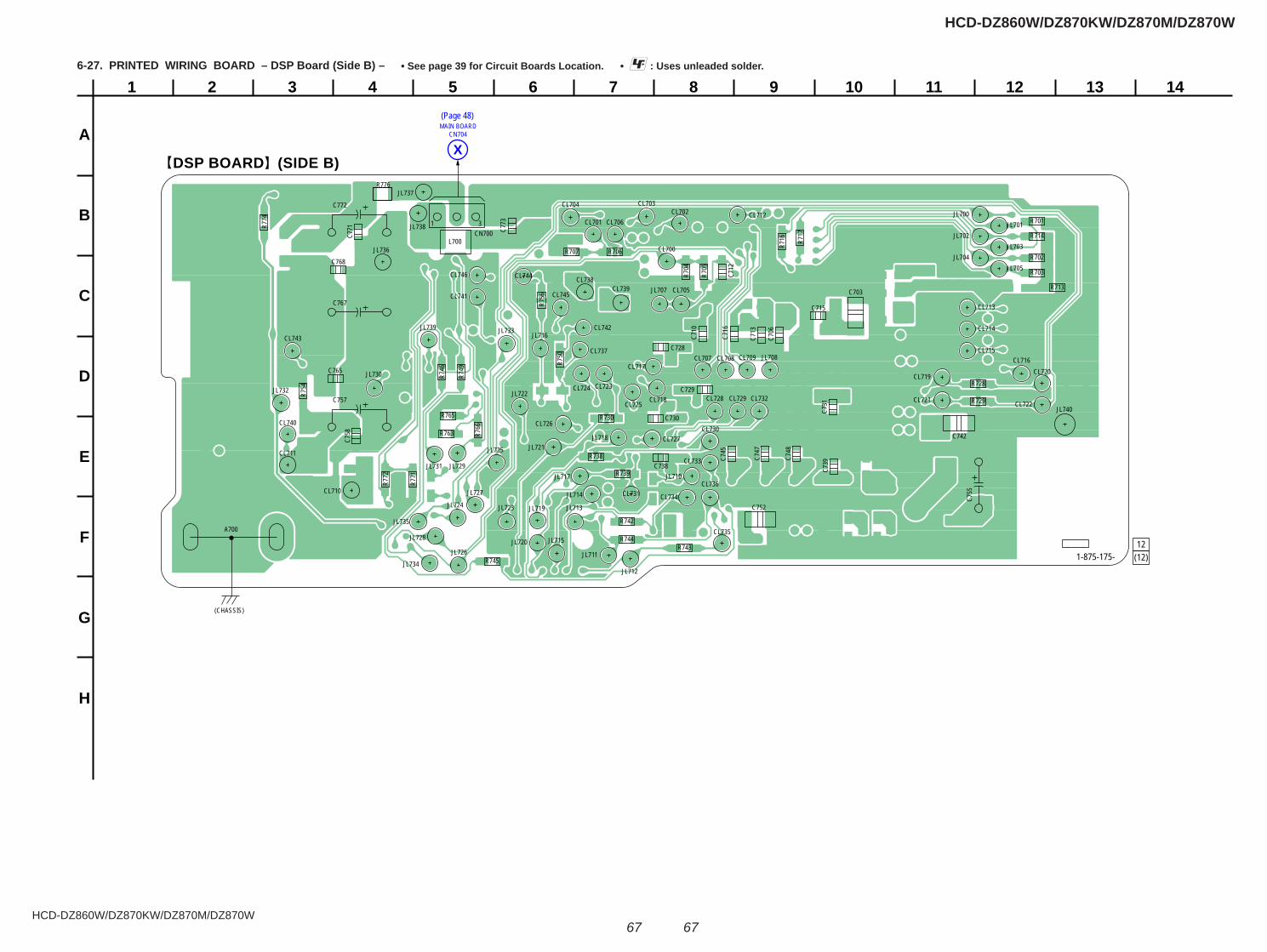
HCD-DZ860W/DZ870KW/DZ870M/DZ870W
HCD-DZ860W/DZ870KW/DZ870M/DZ870W
6767
1
A
B
C
D
E
F
G
H
2 3 4 5 6 7 8 9 10 11 12 13 14
DSP BOARD (SIDE B)
12(12)
MAIN BOARDCN704
X
CL700
CL701CL702
CL703CL704
CL705
CL706
CL707 CL708 CL709
CL710
A700
(CHASSIS)
CL711
CL712
CL713
CL714
CL715CL716
CL717
CL718
CL719CL720
CL721 CL722
CL723CL724
CL725
CL726
CL727
CL728 CL729
CL730
CL731
CL732
CL733
CL734
CL735
CL736
CL737
CL738CL739
CL740
CL741
CL742CL743
CL744
CL745
CL746
L700CN700
1 3 R701
R702
R703R704
R705
R706R707
R713
R714
R716 R7
17
R728
R729
R730
R738
R739
C703
C706
R742
R743R744
R745
R746
R749
C710
C712
C713
R750
C715
C716
R754
R756
JL700JL701
JL702JL703
JL704JL705
JL707
JL708
R763
C728
R765
C729
R766
JL710
JL711
JL712
JL713
C730
JL714
C731
JL715
JL716
JL717
JL718
R771
JL719
R772
R774
C738 C739
R776
JL720
JL721
JL722
JL723JL724
JL725
C742
JL726
JL727
JL728
C745
JL729
C747
C748
JL730
JL731
JL732
JL733
JL734
JL735
C752
JL736
JL737
JL738
JL739
C758
JL740
C772
C757
C767
C765
C768
C771 C7
73
C755
1-875-175-
6-27. PRINTED WIRING BOARD – DSP Board (Side B) – • : Uses unleaded solder.• See page 39 for Circuit Boards Location.
(Page 48)
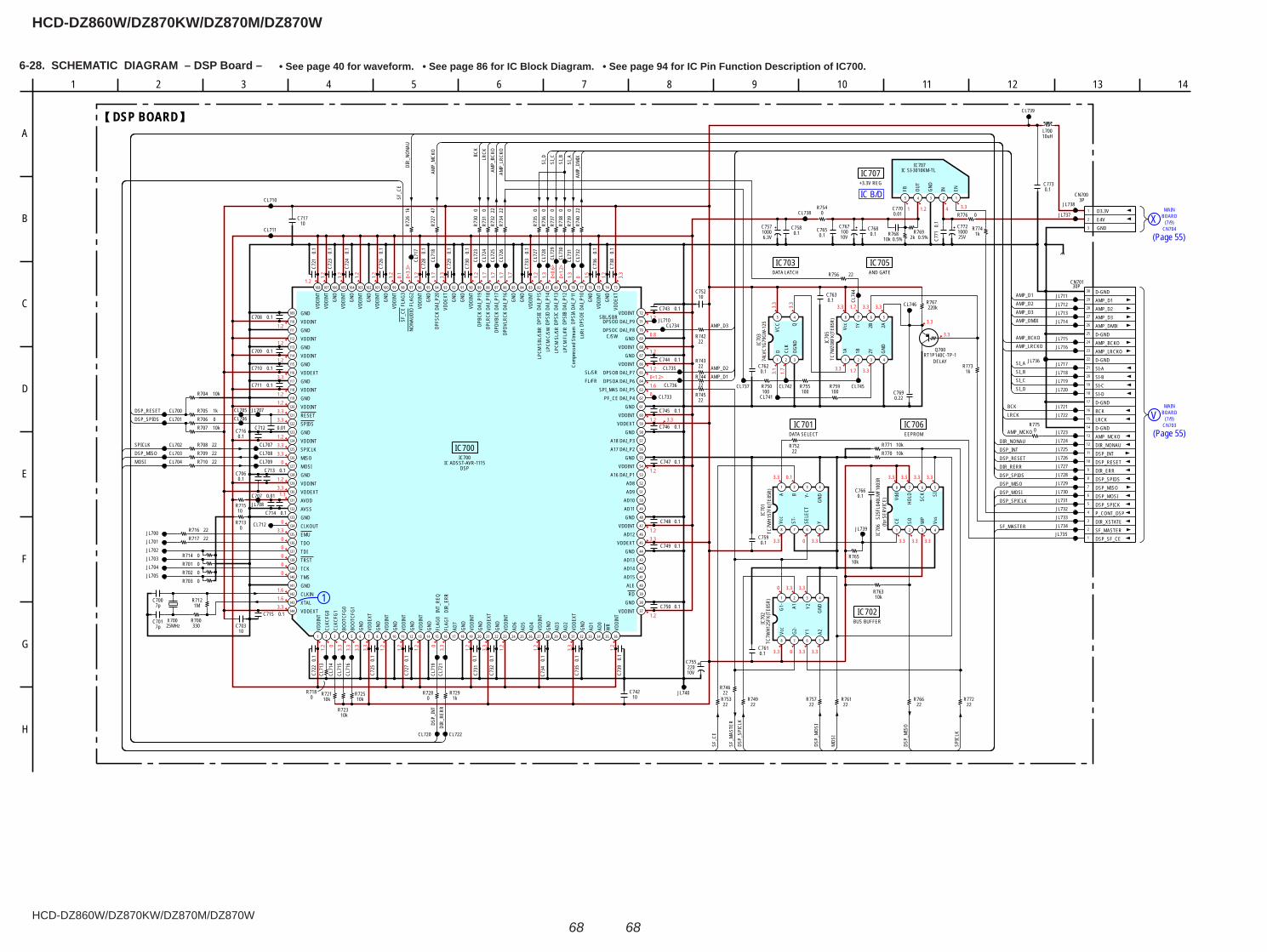
HCD-DZ860W/DZ870KW/DZ870M/DZ870W
HCD-DZ860W/DZ870KW/DZ870M/DZ870W
6868
6-28. SCHEMATIC DIAGRAM – DSP Board – • See page 40 for waveform. • See page 86 for IC Block Diagram. • See page 94 for IC Pin Function Description of IC700.
(7/9)BOARDMAIN
X
(7/9)BOARDMAIN
V
CN704
CN703
1
IC B/D
1.2
1.2
1.2
3.3
1.21.23.33.3
1.23.33.3
0
1.23.31.1
03.3
00000
1.61.63.3
1.2 0
3.3
3.3
3.3
3.3
1.2
1.2
1.2 0
3.3
1.2
3.3
1.2
1.2
3.3
1.2
1.2
3.31.2
1.2
3.31.2
01.60<1.2>1.2
1.2
0.8
1.2
1.2
1.2
1.2
1.2
1.2
1.2
0.1
0<3.
3>1.
2
1.7
3.3
1.2
1.7
1.7
1.7
1.7
1.2
1.3
0<0.
6>0<
1.2>
1.3
0 1.5
1.2
3.3
1 1.2 4 3.3
3.3 1.7 3.3 3.3
3.3 1.7 3.3
3.3
3.3
3.1
1.7
3.3
3.3
3.3 0.1
3.3 0 3.3
3.3 3.3 3.3 3.3
3.3 3.3 3.3
0 3.3 3.3
3.3 0 3.3 3.3
22R708
0R7
38
0.1C773
0R7
30
0.1
C721
0R713
100R75522
R744
47R7
270.1C74610kR707
0.1C749
0.1C743
0.01C707
0.1
C736
0.1
C730
22R756
0.1
C733
0.1
C727
CL710
0.1
C724
10R715
22R717
10C717
0.1C716
1kR705
1kR729
0.1C709
0.1C708
1MR712
1kR7
26
C75522010V
CL712
0.1
C723
10kR723
0.01C712
0.22C769
0.1C745
22R7
32
22R710
6.3V1000C757
0.1
C739
0.1
C735
0.1
C729
1 2 3 4 5 6 7 8 9 10 11 12 13 14 15 16 17 18 19 20 21 22 23 24 25 26 27 28 29 30 31 32 33 34 35 36
37
38
39
40
41
42
43
44
45
46
47
48
49
50
51
52
53
54
55
56
57
58
59
60
61
62
63
64
65
66
67
68
69
70
71
72
737475767778798081828384858687888990919293949596979899100101102103104105106107108
109
110
111
112
113
114
115
116
117
118
119
120
121
122
123
124
125
126
127
128
129
130
131
132
133
134
135
136
137
138
139
140
141
142
143
144
IC ADSST-AVR-1115IC700
VDDI
NTCL
KCFG
0CL
KCFG
1BO
OTCF
G0BO
OTCF
G1GN
DVD
DEXT
GND
VDDI
NTGN
DVD
DINT
GND
VDDI
NTGN
DFL
AG0
INT
_REQ
FLAG
1 D
IR_E
RRAD
7GN
DVD
DINT
GND
VDDE
XTGN
DVD
DINT
AD6
AD5
AD4
VDDI
NTGN
DAD
3AD
2VD
DEXT
GND
AD1
AD0
WR
VDDI
NTVDDINT
GNDRD
ALEAD15AD14AD13GND
VDDEXTAD12
VDDINTGNDAD11AD10
AD9AD8
A16 DAI_P1VDDINT
GNDA17 DAI_P2A18 DAI_P3
GNDVDDEXTVDDINT
GNDPF_CE DAI_P4
SPI_MAS DAI_P5DPSOA DAI_P6DPSOB DAI_P7
VDDINTGND
VDDINTGND
DPSOC DAI_P8DPSOD DAI_P9
VDDINT
VDDE
XTGN
DVD
DINT
GND
DPSO
E DA
I_P1
0DP
SIA
DAI_
P11
DPSI
B DA
I_P1
2DP
SIC
DAI_
P13
DPSI
D DA
I_P1
4DP
SIE
DAI_
P15
VDDI
NTGN
DGN
DDP
DVLR
CK D
AI_P
16DP
DVBC
K DA
I_P1
7DP
LRCK
DAI
_P18
DPBC
K DA
I_P1
9VD
DINT
GND
GND
VDDE
XTDP
FSCK
DAI
_P20
GND
VDDI
NTNO
NAUD
IO F
LAG2
SF_C
E FL
AG3
VDDI
NTGN
DVD
DINT
GND
VDDI
NTGN
DVD
DINT
GND
VDDI
NTVD
DINT
GNDVDDINTGNDVDDINTGNDVDDINTGNDVDDEXTGNDVDDINTGNDVDDINTRESETSPIDSGNDVDDINTSPICLKMISOMOSIGNDVDDINTVDDEXTAVDDAVSSGNDCLKOUTEMUTDOTDITRSTTCKTMSGNDCLKINXTALVDDEXT
0R728
10C703
0.1
C732
0.1
C726
10kR704
0.1
C722
CL711
220kR767
0.1C7620.1C710
22R742
7pC701
0.1C748
0.1C763
0.1C711
25MHzX700
0.1C706
0R7
39
0R7
31
0R706
0.1C765
10C752
22R743
22R709
0.1C750
JL708
CL733
22R716
100R750
0R718
0.1C744
0.1
C738
10kR721
0.1
C734
0.1
C728
7pC700
0.1
C725
0.1
C731
JL707
0R701
100R759
330R700
22R7
34
0.1C714
0R776
0.1C713
10C742
0.1C747
0.1C715
10kR725
8 7 6 5
4321TC7W
Z08F
K(TE
85R)
IC70
5
1A 1B 2Y GND
2A2B1YVcc
JL738
JL737
JL711JL712JL713
JL715JL716
JL736 JL717JL718
JL721JL722
JL723JL724JL725JL726JL727JL728JL729JL730JL731JL732JL733
CL700CL701
CL702CL703CL704
CL720 CL722
CL735
CL734
CL736
CL741
CL737 CL742 CL745
CL746
CL74
4
CL738
CL739
CL73
1CL
730
CL72
6CL
725
CL72
4CL
723
CL71
8
CL71
7CL705CL706
CL707CL708CL709
CL71
3
CL71
4CL
715
CL71
6
CL71
9CL
721
0.5%10kR7680.1
C76810V100
C767
12345
IC SI-3010KM-TLIC707
ENINGND
OUT
FB
1kR774
0.5%2kR769
0.1
C771 25V
1000C772
JL700JL701JL702JL703JL704JL705
1kR773
JL710
0R775
8 7 6 5
4321
TC7W
H157
FK(T
E85R
) IC
701
A B Y-
GND
YSELE
CT
ST-
Vcc
TC7W
H125
FK(T
E85R
)IC
702
G1-
A1 Y2
GND
A2Y1G2-
Vcc
22R745
22R746
22R749
22R757
22R766
22R761
22R772
22R752
22R753
10kR771
10kR765
10kR763
10kR770
JL734JL735
RT1P140C-TP-1Q700
DELAY
0.1C758
0.1C766
0.1C759
0.1C761
0R7
35
5 4
32174LV
C1G7
9GW
-125
IC70
3
D CLK
DGND
Q
VCC
10uHL700
0.01C770
JL714
JL719JL720
0R7
370
R736
22R7
40
R7540
CL73
2
CL72
9CL
728
CL72
7
0R714
0R7020R703
JL7391
2
3
4
5
6
7
8
9
10
11
12
13
14
15
16
17
18
19
20
21
22
23
24
25
26
27
28
29
3030P
CN701
DSP_SF_CESF_MASTERDIR_XSTATEP_CONT_DSPDSP_SPICKDSP_MOSIDSP_MISODSP_SPIDSDIR_ERRDSP_RESETDSP_INTDIR_NONAUAMP_MCKOD-GNDLRCKBCKD-GNDSI-DSI-CSI-BSI-AD-GNDAMP_LRCKOAMP_BCKOD-GNDAMP_DMIXAMP_D3AMP_D2AMP_D1D-GND
1
2
3
3PCN700
D3.3VE4VGND
8 7 6 5
4321
IC70
6S2
5FL0
40LM
F100
3R(fo
r SER
VICE
)
CE SO WP
Vss
SI
SCK
HOLDVd
d
JL740
DSP_RESET
BCK
AMP_
MCK
ODI
R_RE
RRDS
P_IN
T
SI_A
AMP_D1
AMP_
BCKO
AMP_D2
LRCK
AMP_D3
AMP_D3
AMP_D1AMP_D2
DIR_
NONA
U
AMP_MCKO
DSP_
MIS
O
MOS
I
SF_M
ASTE
R
SF_C
E
DSP_MISOSPICLK
DSP_
SPIC
LK
DSP_
MOS
I
SI_B
SF_MASTER
DSP_SPICLKDSP_MOSIDSP_MISODSP_SPIDSDIR_RERRDSP_RESETDSP_INTDIR_NONAU
LRCKBCK
AMP_DMIX
SI_ASI_BSI_CSI_D
AMP_LRCKOAMP_BCKO
SI_C
SI_D
SPIC
LK
AMP_
DMIX
DSP_SPIDS
MOSI
SF_C
E
AMP_
LRCK
O
Com
pres
sed
Stre
amLP
CM F
L/FR
LPCM
SL/
SRLP
CM C
/SW
LPCM
SBL
/SBR
FL/FRSL/SR
C/SW
SBL/SBR
Lt/R
t
DSP BOARD
DSP
IC700
IC701DATA SELECT
IC706EEPROM
IC702BUS BUFFER
IC703 IC705DATA LATCH AND GATE
IC707+3.3V REG
3 8
D
134
E
H
G
105 11
C
A
127 9 14
B
2 6
F
1
8 7 6 5
4321
(Page 55)
(Page 55)
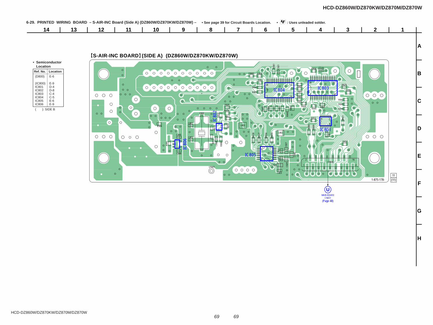
HCD-DZ860W/DZ870KW/DZ870M/DZ870W
HCD-DZ860W/DZ870KW/DZ870M/DZ870W
6969
6-29. PRINTED WIRING BOARD – S-AIR-INC Board (Side A) (DZ860W/DZ870KW/DZ870W) – • : Uses unleaded solder.• See page 39 for Circuit Boards Location.
1234567891011121314
A
B
C
D
E
F
G
H
S-AIR-INC BOARD (SIDE A) (DZ860W/DZ870KW/DZ870W)
11(11)
MAIN BOARDCN651
U
IC805
IC804 IC803
IC801
IC80
2
IC80
6
1
16
8
9
1 14
1528
1 14
1528
14 1
8 7
1
2
17
16
FB801
R805
R806
R808
R809
R811
R812
R813
R814
R815
CN800
R821R8
24
R826
R827
R828
R829
LP801
R830
R834
R835
R836
R837
R838
R839
C800
C802
R840
R841
C807
R843
R844 R845 R847
R849
X800
R850
R851
R852
R855
R856
R858
R859
C820C8
21C8
22
C823
C824
R860
R861
R862
C827
R863
C828
R864
C829
R865
C844
C845
C846
R895
R904
L802
L803
1-875-178-
(Page 48)
Ref. No. Location
• Semiconductor Location
(D800) E-6
(IC800) E-9 IC801 D-4 IC802 D-8 IC803 C-4 IC804 C-5 IC805 E-6 IC806 E-9 ( ): SIDE B
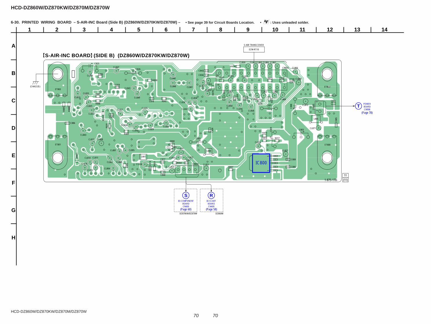
HCD-DZ860W/DZ870KW/DZ870M/DZ870W
HCD-DZ860W/DZ870KW/DZ870M/DZ870W
7070
6-30. PRINTED WIRING BOARD – S-AIR-INC Board (Side B) (DZ860W/DZ870KW/DZ870W) – • : Uses unleaded solder.• See page 39 for Circuit Boards Location.
1
A
B
C
D
E
F
G
H
2 3 4 5 6 7 8 9 10 11 12 13 14
S-AIR-INC BOARD (SIDE B) (DZ860W/DZ870KW/DZ870W)
11(11)
POWERBOARDCN908
T
IO-COMPONENTBOARDCN409
SIO-SCART
BOARDCN409
R
IC800
15
R800
R801
R807
DZ860WDZ870KW/DZ870W
R810
R817R818
R819
R822
R831 R832
C801
C804
C806
R842
C808
R846
R848
C814
C817
C818
C819
C830
C833
C834
C835
R872
C836R873
CN803R874
R876
R877
19
20
1
2R878
R879
C840
C841CN804
1 4
C843R8
80
R881
R889
R896
R898
D800
C882
CN80
51
2
C888
C885
C886
CL800
CL801
CL802
CL803
CL804
CL805
CL808
CL811
CL812
CL813
CL814
CL815
CL816CL820
CL821
C805
C805
C803C809
CL822
CL826
CL827
CL828CL829
CL830CL831
CL832
CL833
CL834
CL835
CL836
CL837
CL838
CL839
CL840
CL841
CL842
CL843
CL844
C825
CL845
CL847C826
CL848
CL849
CL850CL851
CL852
CL853
CL854
CL855
CL856
CL857
L800
CL858
L801
CL859
L805
CL860
CL861
CL862
CL863
CL864
CL865
CL866
CL867
CL868
CL869
CL870
CL871
CL872
ET803ET802
ET801 ET800
(CHASSIS)
1-875-178-
S-AIR TRANSCEIVER
EZW-RT10
(Page 60) (Page 58)
(Page 78)
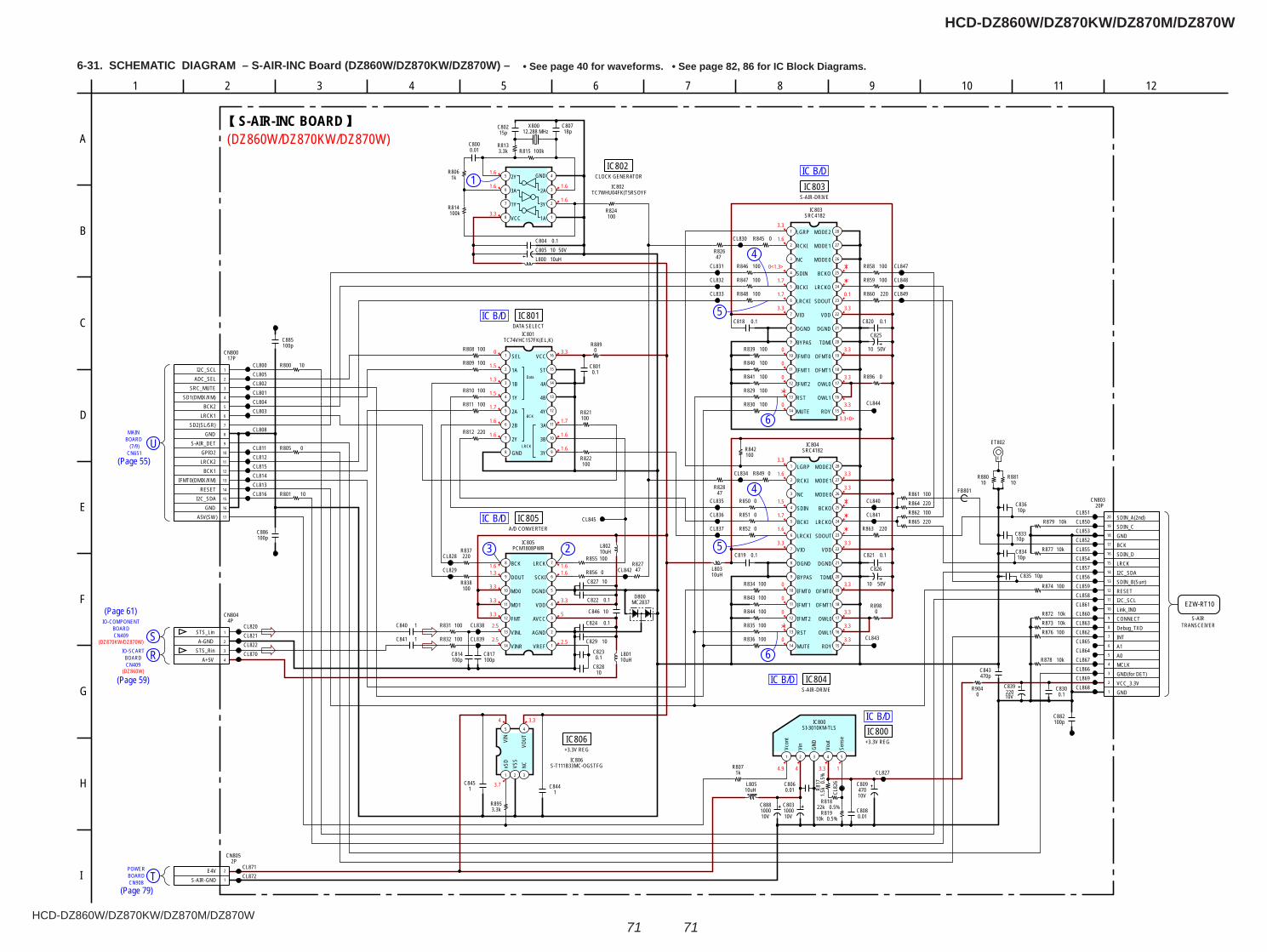
HCD-DZ860W/DZ870KW/DZ870M/DZ870W
HCD-DZ860W/DZ870KW/DZ870M/DZ870W
7171
6-31. SCHEMATIC DIAGRAM – S-AIR-INC Board (DZ860W/DZ870KW/DZ870W) – • See page 40 for waveforms. • See page 82, 86 for IC Block Diagrams.
5
4
6
5
4
6
1
3 2
BOARD(7/9) U
MAIN
CN651
BOARDCN409
RIO-SCART
SIO-COMPONENT
CN409BOARD
BOARDCN908
TPOWER
IC B/D
IC B/D
IC B/D
IC B/D
IC B/D
1.6
1.6
3.3
1.6
1.6
0
1.5
1.3
1.5
1.7
1.6
1.6
3.3
1.7
1.6
1.6
1.61.6
3.3
5
2.5
1.61.3
3.3
3.3
3.3
2.5
2.5
4 3.3
3.7
4.9 4 3.3 1
3.3
1.6
1.5
1.7
1.6
3.3
0
0
0
0 3.3
3.3
3.3
3.3
3.3
3.3
3.3
3.3
1.6
0<1.3>
1.7
1.7
3.3
0
0
0
0
3.3<0>
3.3
3.3
3.3
3.3
0.1
(DZ870KW/DZ870W)
(DZ860W)
(DZ860W/DZ870KW/DZ870W)
C834
14
13
12
11
10
9
8 7
6
5
4
3
2
1
PCM1808PWRIC805
VREF
AGND
AVCC
VDD
DGND
SCKI
LRCKBCK
DOUT
MD0
MD1
FMT
VINL
VINR
R842100
100R847 100R859
100R829
0.1C818
CL844
220R860
100R830
0R845
100R839
28
27
26
25
24
23
227
6
5
4
3
2
1
21
20
16
17
18
19
13
12
11
10
8
9
1514
SRC4182IC803
LGRP
RCKI
NC
SDIN
BCKI
LRCKI
VIO
DGND
BYPAS
IFMT0
IFMT1
IFMT2
RST
MUTE RDY
OWL1
OWL0
OFMT1
OFMT0
TDMI
DGND
VDD
SDOUT
LRCKO
BCKO
MODE0
MODE1
MODE2
100R848
100R840
100R846
100R841
100R858
100R836
220R864
100R835
0R849
100R843
0.1C819
28
27
26
25
24
23
227
6
5
4
3
2
1
21
20
16
17
18
19
13
12
11
10
8
9
1514
SRC4182IC804
LGRP
RCKI
NC
SDIN
BCKI
LRCKI
VIO
DGND
BYPAS
IFMT0
IFMT1
IFMT2
RST
MUTE RDY
OWL1
OWL0
OFMT1
OFMT0
TDMI
DGND
VDD
SDOUT
LRCKO
BCKO
MODE0
MODE1
MODE2
100R834
CL843
220R863220R865
0R850
100R844
220R837
100R838
100R855
CL835
CL836
CL837
CL831
CL832
CL833
C817100p
C814100p
100R831
CL834
CL830
16
15
14
13
12
11
10
98
7
6
5
4
3
2
1
IC801TC74VHC157FK(EL,K)
SEL
1A
1B
1Y
2A
2B
2Y
GND 3Y
3B
3A
4Y
4B
4A
ST
VCC
0.1C801100R809
100R811
100R808
100R874
R878 10k
R873 10kR872 10k
100R876
R879 10k
R877 10k
CL850
CL852CL853
CL854CL855
CL856CL857
CL858CL859
CL860CL861
CL862CL863
CL864CL865
CL867
CL868CL869
CL847
CL848
CL849
CL828
CL829
CL838
CL839
CL800
CL801CL802
CL803CL804
CL805
CL808
CL811CL812
CL813CL814CL815
CL816
CL820CL821CL822
10R800
10R801
100R821
0R856
100R832
47R828
47R826
47R827
8
7
6
5 4
3
2
1
TC7WHU04FK(T5RSOYFIC802
1A
3Y
2A
GND2Y
3A
1Y
VCC
15pC802
100kR815
18pC807
3.3kR813
12.288 MHzX800
1kR806
100kR814
0.01C800
100R810
220R812
100R822
0R851
0R852
0R805
50V10C8050.1C804
10uHL800
0.1C823
0.1C824
10uHL801
0.1C822
CL845
CL842
50V10
C826
0.1C821
0.1C820
50V10
C825
100R824
100R861
100R862
CL840
CL841
MC2837D800
ET802
CL866
CL851
C83310p
C83610p
10p
C835 10p
1
2
3
4
5
6
7
8
9
10
11
12
13
14
15
16
17
18
19
20
20PCN803
GNDVCC_3.3VGND(for DET)MCLKA0A1INTDebug_TXDCONNECTLink_INDI2C_SCLRESETSDIN_B(Surr)I2C_SDALRCKSDIN_DBCKGNDSDIN_CSDIN_A(2nd)
10uHL802
10uHL803
10V
C839220
10R880
10R881
C840 1
C841 1
CL870
R8890
1C845
3.3kR895
1C844
5 4
321
S-T111B33MC-OGSTFGIC806
xSD
VSS
NCVO
UTVIN
10V1000C803
0.01C8080.5%22k
R818
0.5%
1.5kR8
17
CL82
6
1 2 3 4 5
SI-3010KM-TLSIC800
Vcon
t
Vin
GND
Vout
Sens
e
R8071k
0.01C806
CL827
0.5%10kR819
C843470p
0.1C830
CL871CL872
C882100p
100pC886
100pC885
FB801
10C827
10C829
10C846
1
2
3
4
5
6
7
8
9
10
11
12
13
14
15
16
17
17PCN800
)
1
2
3
4
4PCN804
STS_LinA-GND
STS_RinA+5V
10C828
1
2
2PCN805
S-AIR-GNDE4V
10V1000C888
0R904
L80510uH
10V470
C809
0R896
0R898
BCK
LRCK
Data
S-AIR-INC BOARD
A/D CONVERTERIC805
DATA SELECTIC801
CLOCK GENERATORIC802
+3.3V REGIC806 +3.3V REG
IC800
S-AIR-DRIVEIC803
S-AIR-DRIVEIC804
EZW-RT10
S-AIRTRANSCEIVER
71 8
H
D
G
B
63
E
C
2 10
I
4
A
1195 12
F
I2C_SCLADC_SEL
SRC_MUTESD1(DMIX/XM)
BCK2LRCK1
SD2(SL/SR)GND
S-AIR_DETGPIO2LRCK2
BCK1IFMT0(DMIX/XM)
RESETI2C_SDA
GNDA5V(SW
E(Page 55)
(Page 61)
(Page 59)
(Page 79)
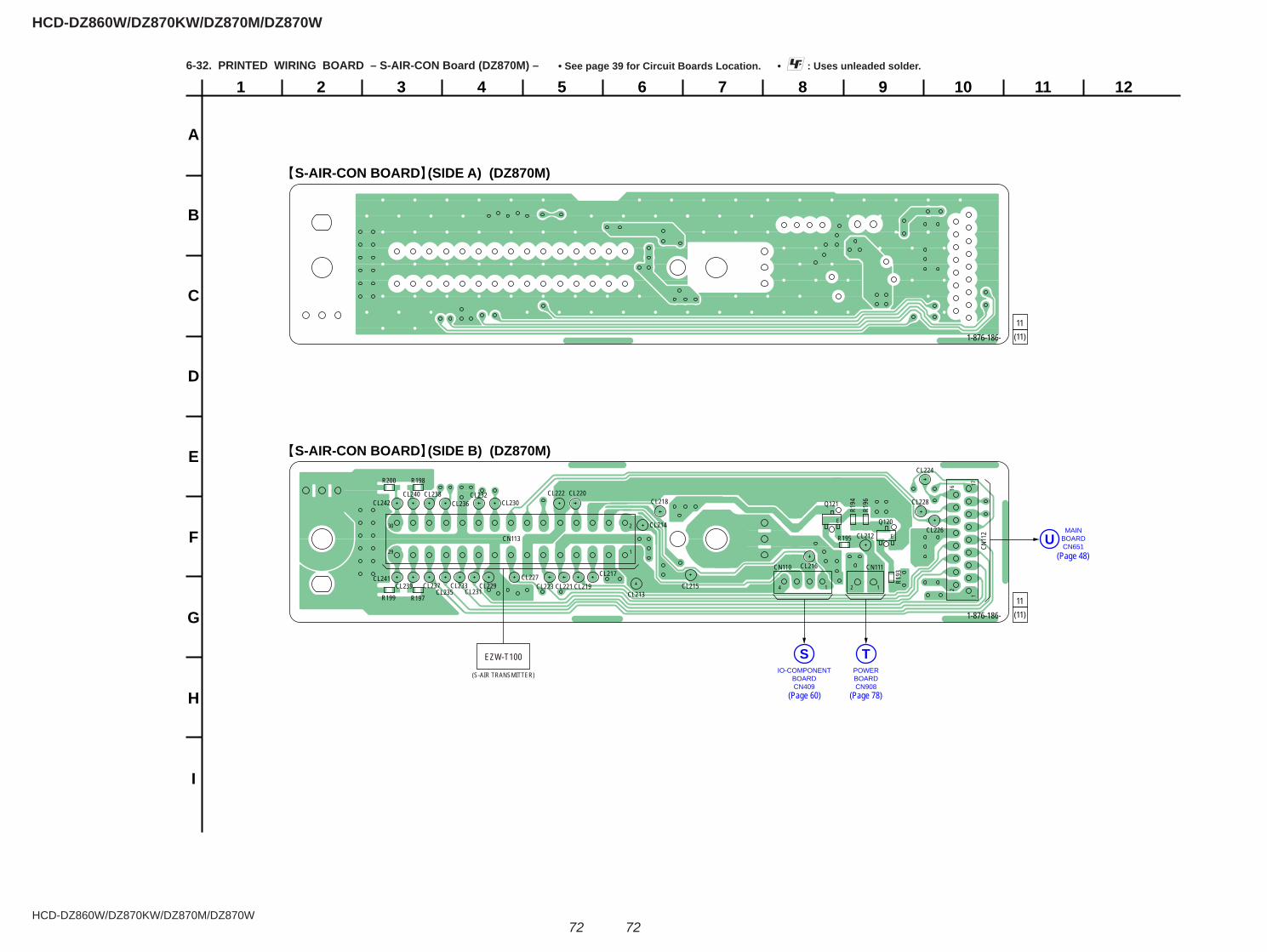
HCD-DZ860W/DZ870KW/DZ870M/DZ870W
HCD-DZ860W/DZ870KW/DZ870M/DZ870W
7272
6-32. PRINTED WIRING BOARD – S-AIR-CON Board (DZ870M) – • : Uses unleaded solder.• See page 39 for Circuit Boards Location.
1
A
B
C
D
E
F
G
H
I
2 3 4 5 6 7 8 9 10 11 12
Q120
Q121
CL212
CL213
CL214
CL215
CL216CL217
CL218
CL219
CL220
CL221
CL222
CL223
CL224
CL226
CL227
CL228
CL229
CL230
CL231
CL232
CL233CL235
CL236
CL237CL239
R195
R197R199
CL241
CL242
CN113
R198R200
R194
R196
E
E
CN11
2
R193
CN110 CN111
CL238CL240
216
171
11
1
2
29
30
4 2
EZW-T100
(S-AIR TRANSMITTER)
S-AIR-CON BOARD (SIDE A) (DZ870M)
S-AIR-CON BOARD (SIDE B) (DZ870M)
11(11)1-876-186-
11(11)1-876-186-
MAINBOARDCN651
U
POWERBOARDCN908
TIO-COMPONENT
BOARDCN409
S
(Page 60) (Page 78)
(Page 48)
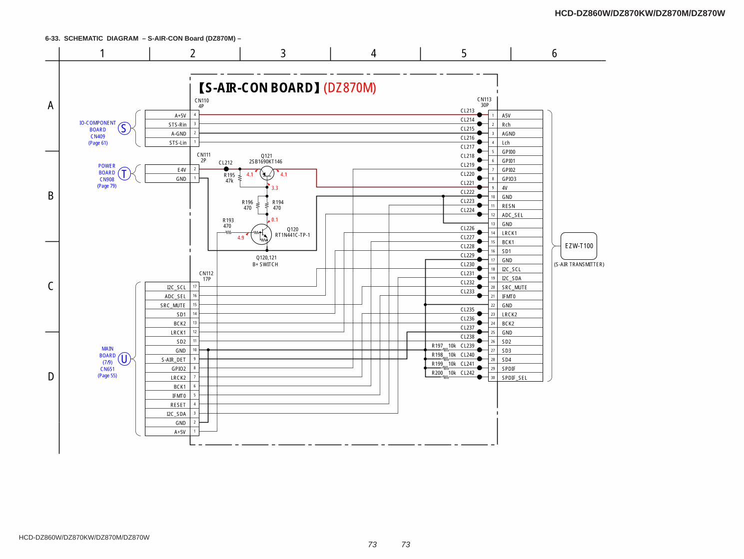
HCD-DZ860W/DZ870KW/DZ870M/DZ870W
HCD-DZ860W/DZ870KW/DZ870M/DZ870W
7373
CN409SIO-COMPONENT
BOARD
TCN908BOARDPOWER
BOARDMAIN
(7/9) UCN651
4.1
3.3
0.1
4.1
4.9
(DZ870M)
CL226
CL236
CL233
470R194
CL240
CL213
CL212
CL239
CL228
CL224
CL214
CL217
CL232
CL222
CL220
CL227
CL218
CL221
CL219
CL235
CL216
CL223
CL238
CL215
CL242
CL230
470R193
CL231
CL241
2SB1690KT146Q121
RT1N441C-TP-1Q120
47kR195
470R196
10kR19710kR19810kR19910kR200
1
2
3
4
5
6
7
8
9
10
11
12
13
14
15
16
17
18
19
20
21
22
23
24
25
26
27
28
29
30
30PCN113
A5VRchAGNDLchGPI00GPI01GPI02GPIO34VGNDRESNADC_SELGNDLRCK1BCK1SD1GNDI2C_SCLI2C_SDASRC_MUTEIFMT0GNDLRCK2BCK2GNDSD2SD3SD4SPDIFSPDIF_SEL
1
2
3
4
5
6
7
8
9
10
11
12
13
14
15
16
17
CN11217P
A+5VGND
I2C_SDARESETIFMT0BCK1
LRCK2GPIO2
S-AIR_DETGNDSD2
LRCK1BCK2
SD1SRC_MUTE
ADC_SELI2C_SCL
CL229
CL237
1
2
3
4
CN1104P
STS-LinA-GND
STS-RinA+5V
1
2
2PCN111
GNDE4V
S-AIR-CON BOARD
Q120,121B+ SWITCH
EZW-T100
(S-AIR TRANSMITTER)
B
3
A
D
5 61 4
C
26-33. SCHEMATIC DIAGRAM – S-AIR-CON Board (DZ870M) –
(Page 61)
(Page 79)
(Page 55)

HCD-DZ860W/DZ870KW/DZ870M/DZ870W
HCD-DZ860W/DZ870KW/DZ870M/DZ870W
7474
1
A
B
C
D
E
F
G
2 3 4 5 6 7 8 9 10 11
SERIPARA (DSR) BOARD
11(11)
DZ870KW/DZ870M/DZ870W
DZ860W
IO-COMPONENTBOARDCN415
W
IO-SCARTBOARDCN415
W
MAIN BOARDCN625
K
IC600
1 13
11415
28
R601
R602
R603
R604
R606
R608
R609
R610R611 R612
R613 R614
R615 R616
R617 R618
R619
CN600
CN601
C600
C601
JL600
JL601JL602
JL603
JL604JL605
JL606JL607
JL608JL609
JL610 JL611 JL612
JL613
JL614
JL615
JL616
JL617
JL618
JL619
JW70
2
JW703
JW704
JW70
7
JW70
817
65
JW709
JW71
0
JW711
1-875-176-
6-34. PRINTED WIRING BOARD – SERIPARA (DSR) Board – • : Uses unleaded solder.• See page 39 for Circuit Boards Location.
(Page 48)
(Page 60)
(Page 58)
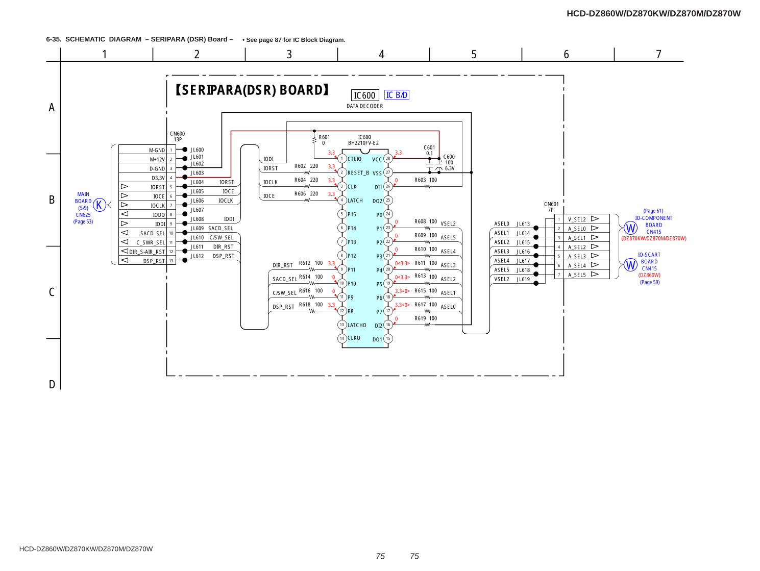
HCD-DZ860W/DZ870KW/DZ870M/DZ870W
HCD-DZ860W/DZ870KW/DZ870M/DZ870W
7575
6-35. SCHEMATIC DIAGRAM – SERIPARA (DSR) Board – • See page 87 for IC Block Diagram.
BOARD(5/9) KMAIN
W BOARDIO-COMPONENT
CN415
CN415W BOARDIO-SCART
CN625
IC B/D
3.3
3.3
3.3
3.3
3.3
0
0
3.3
3.3
0
0
0
0
0<3.3>
0<3.3>
3.3<0>
3.3<0>
0
(DZ870KW/DZ870M/DZ870W)
(DZ860W)
JL604
JL608
1
2
3
4
5
6
7
8
9
10
11
12
13
13PCN600
M-GNDM+12VD-GNDD3.3VIORST
IOCEIOCLKIODOIODI
SACD_SELC_SWR_SEL
DIR_S-AIR_RSTDSP_RST
JL612
220R604JL603
220R602
100R619
220R606
JL607
JL611
JL602
JL606
JL610
28
27
26
25
24
23
227
6
5
4
3
2
1
21
20
16
17
18
19
13
12
11
10
8
9
1514
BH2210FV-E2IC600
CTLIO
RESET_B
CLK
LATCH
P15
P14
P13
P12
P11
P10
P9
P8
LATCHO
CLKO DO1
DI2
P7
P6
P5
P4
P3
P2
P1
P0
DO2
DI1
VSS
VCCJL601JL600
JL605
0.1C601
100R603
JL609
JL619JL618JL617JL616JL615JL614JL613100R608
100R609
100R610
100R611
100R613
100R615
100R617
100R612
100R614
100R616
100R618
6.3V100
C600
1
2
3
4
5
6
7
7PCN601
V_SEL2A_SEL0A_SEL1A_SEL2A_SEL3A_SEL4A_SEL5
0R601
IODI
IORST
IOCLK
IOCLKIOCE
IOCE
IORST
SACD_SELC/SW_SEL
DIR_RSTDSP_RST
SACD_SEL
DIR_RST
DSP_RST
C/SW_SEL
ASEL0ASEL1ASEL2ASEL3ASEL4ASEL5VSEL2
VSEL2
ASEL5
ASEL4
ASEL3
ASEL2
ASEL1
ASEL0
IODI
DATA DECODERIC600SERIPARA(DSR) BOARD
41
D
A
72 3
B
5
C
6
(Page 53)
(Page 61)
(Page 59)
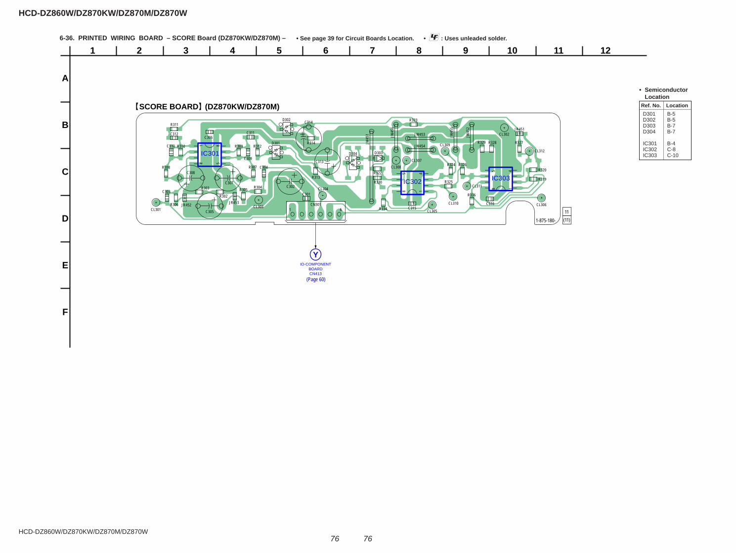
HCD-DZ860W/DZ870KW/DZ870M/DZ870W
HCD-DZ860W/DZ870KW/DZ870M/DZ870W
7676
6-36. PRINTED WIRING BOARD – SCORE Board (DZ870KW/DZ870M) – • : Uses unleaded solder.• See page 39 for Circuit Boards Location.
1
A
B
C
D
E
F
2 3 4 5 6 7 8 9 10 11 12
SCORE BOARD (DZ870KW/DZ870M)
11(11)1-875-180-
IO-COMPONENTBOARDCN413
Y
IC302
IC301
IC303
8 145
JR
JR
JR
CL301
CL302
CL303
CL304
CL305CL306
CL307CL308
CL309
CL310
CL311
CL312
JW453
JW454
JR451
R302
JR452
R303
JR453
R304R305
R306
R307R308
R309R310
R311
R312
R313
R314
CN301
R322
R323
R325
R327R328R329
R330
R334
R336C301
C302C303
C304
C305
C306
C307
C308
C309
C310
C311C312
C313
C314
C315C316
D301
D302
D303D304
R319
R320
1 6
814 5
JW45
1 JW45
6
8 145
R324 R326
JW45
2
JW45
5
Ref. No. Location
• Semiconductor Location
D301 B-5 D302 B-5 D303 B-7 D304 B-7
IC301 B-4 IC302 C-8 IC303 C-10
(Page 60)
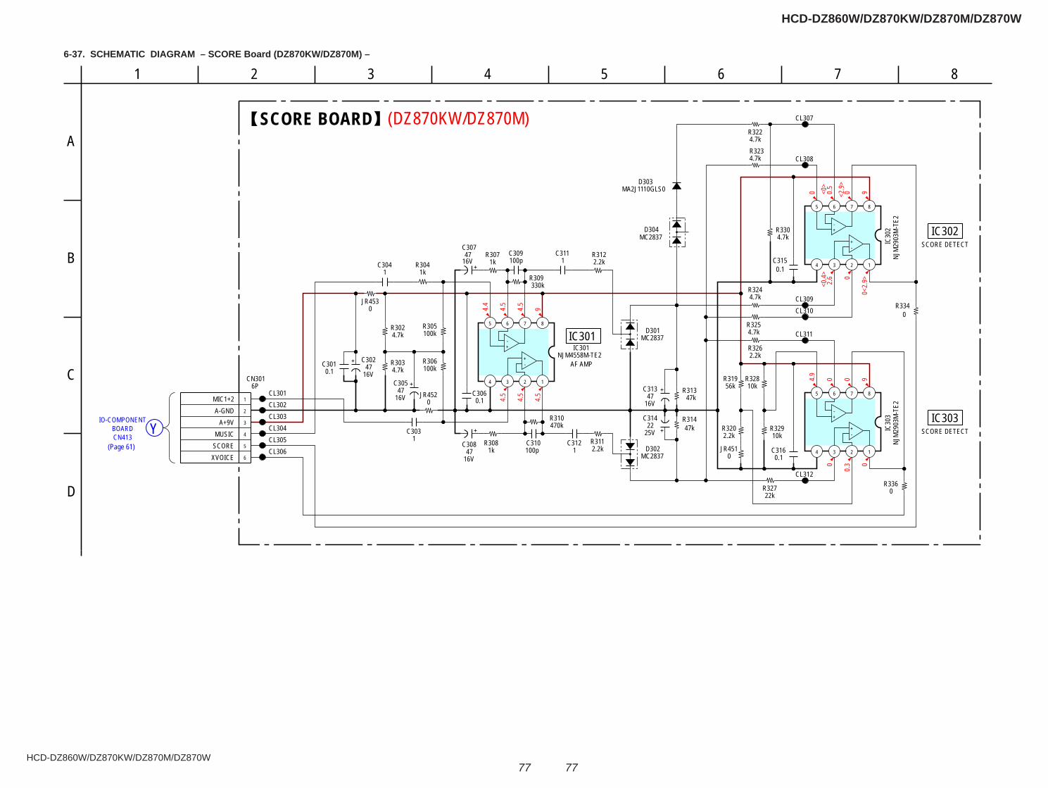
HCD-DZ860W/DZ870KW/DZ870M/DZ870W
HCD-DZ860W/DZ870KW/DZ870M/DZ870W
7777
BOARDCN413
YIO-COMPONENT
4.4
4.5
4.5
9
4.5
4.5
4.5
0 0.5
0 9<0>
<2.9
>2.
6<0
.4> 0
0<2.
9>
4.9
0 0 9
0
0.3 0
(DZ870KW/DZ870M)
16V47
C302
16V47
C305
16V47
C308
100kR305
1C303 47k
R314
1kR307
16V47
C307
2.2kR311
2.2kR312
47kR313
16V47
C3138765
4 3 2 1
NJM
2903
M-T
E2IC
303
8765
4 3 2 1
NJM
2903
M-T
E2IC
302
22kR327
0.1C306
0.1C316
56kR319
R32910k
2.2kR326
4.7kR325
4.7kR324
0.1C315
4.7kR3234.7kR322
4.7kR330
0R336
1kR304
4.7kR302
4.7kR303
CL301CL302CL303CL304CL305CL306
CL307
CL308
CL309CL310
CL311
CL312
0.1C301 100k
R306
330kR309
R3202.2k
10kR328
25V22
C314470kR310
1kR308
8765
4 3 2 1
NJM4558M-TE2IC301
100pC310
100pC309
MC2837D302
MC2837D301
MC2837D304
1C304 1
C311
1C312
1
2
3
4
5
6
6PCN301
MIC1+2A-GND
A+9VMUSIC
SCOREXVOICE
MA2J1110GLS0D303
0R334
0JR452
0JR453
0JR451
-+
+-
-+
+-
-+
+-
SCORE BOARD
SCORE DETECT
SCORE DETECT
AF AMP
IC301
IC303
IC302
85
C
6
D
1 4
A
72
B
36-37. SCHEMATIC DIAGRAM – SCORE Board (DZ870KW/DZ870M) –
(Page 61)
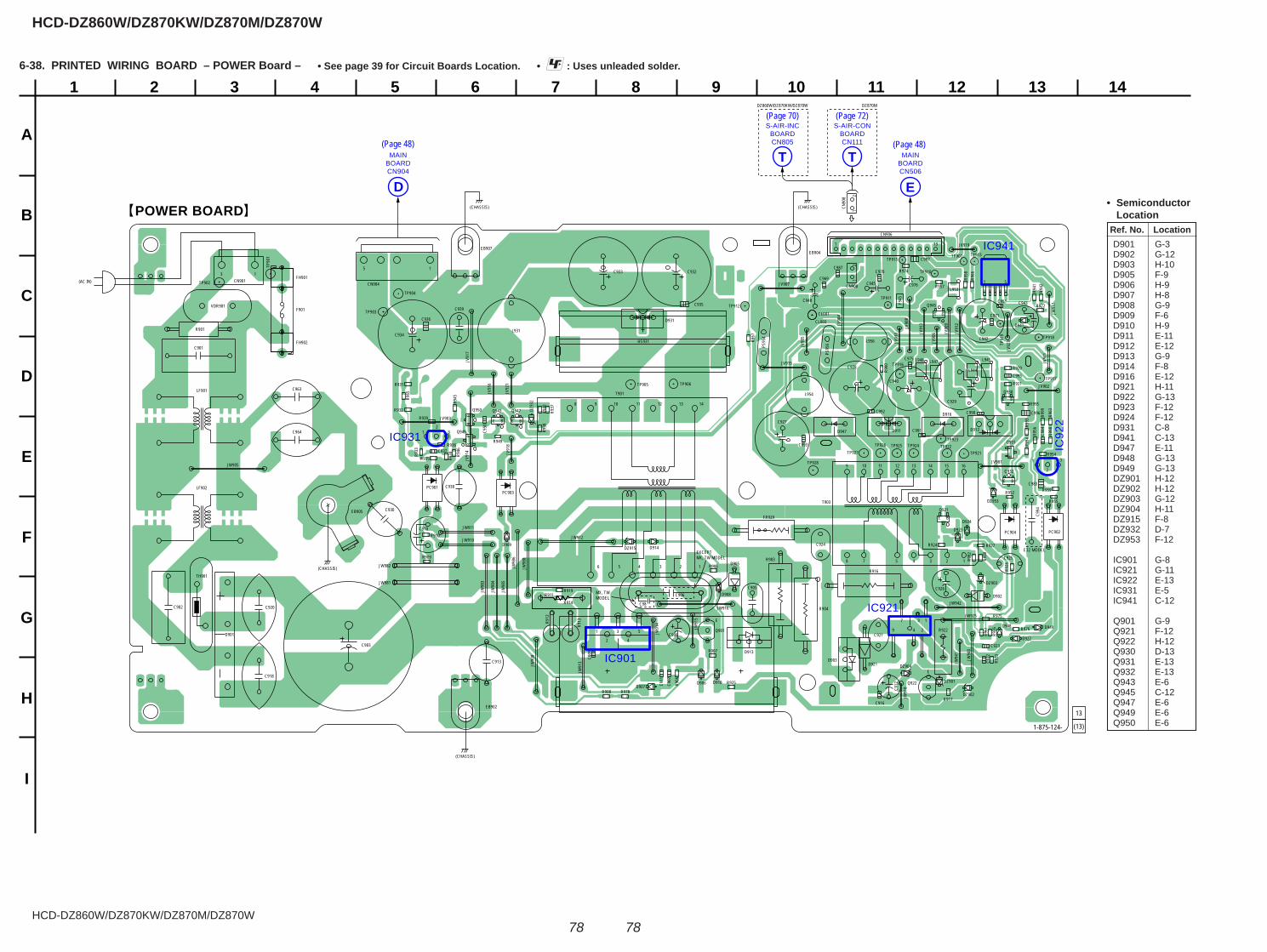
HCD-DZ860W/DZ870KW/DZ870M/DZ870W
HCD-DZ860W/DZ870KW/DZ870M/DZ870W
7878
1
A
B
C
D
E
F
G
H
I
2 3 4 5 6 7 8 9 10 11 12 13 14
POWER BOARD
E
13
(13)1-875-124-
E32 MODELEXCEPTMX, TW MODEL
MX, TWMODEL
DZ870MDZ860W/DZ870KW/DZ870W
MAINBOARDCN904
D
MAINBOARDCN506
E
S-AIR-CONBOARDCN111
T
S-AIR-INCBOARDCN805
T
IC941
IC92
2
IC921
IC931
IC901
9
BE
GS
BE
1 5
BE
BE
BE
BE
BE
BE
DZ904
D941
D947
D948 D949
HS931
DZ915
DZ93
2
JW981
JW982
JW98
3
JW98
4
JW98
5
JW98
6
JW98
8
DZ953
TP90
1
TP902
TP903
TP904
TP905 TP906
TP907
F901
TP911
TP912
TP913
1 13
TP915
TP916
TP917
TP918
TP91
9
TP921TP922
TP923TP924TP925TP926
TP927
TP928
Q921
Q922
PC901
PC902
PC903
PC904
(AC IN)
EB902
Q930
EB904
Q931
EB905
Q932
EB907
Q943
L931
Q945
Q947
Q949
Q950
VDR901
L944
L945L947L948
R901
R903
R904
R905123456
8 9 10 11 12 13 14
R906
L953
R907
L954
R908
R909
L956
R910
R911
R914
R916
R917
R919
CN9011
153
CN904
R920
CL001
R921
CN906
R922
137
249
CL003
R923
R924
1234578
9 10 11 12 13 14 15 16
R925
R926
R927
R928
R930
C994
JV901
R931 JV902
R932
JV903R9
33
JV90
4
R934
JV90
5
R935
JV90
6
R936
R937
JV907
JV90
8
R938
JV90
9
R939
FR929
FH901
C901FH902
C902
C903
R940
JV91
0F9
45
JV91
1
TH901
C905
R941
JV91
2
C906
C98
R942
JV91
3
C907
JV91
4
C908
JV915
R945
C909
JV91
6
R946
JV91
7
JV91
8
JV919
R949
C910
C911
C912
C913
JV92
1
R951
C916
R952
JV92
3
C918
R9541
2
3
LF901
R955
LF902
R956
R957
R958
R959
C920
C921
C922
C923
R960
C924
C925
C926
C927
R963
C928
C929R965
R966
R967
C930
C932C933
C934
C935 R972
C936
C937
C938
R975
C939
R976
R978
C940
C942
C943
C945
C950
C951
R992
R993
R994
R995
JW905
JW90
8
R998
R999
D901
D902
D903
C963
JW910
C964
JW911
D905
JW912
D906
JW91
3
D907
JW91
4
D908
JW91
5
D909
JW916
JW91
7
JW91
8
D910
C970
D911
C971
D912
D913
D914
C975
D916
C976
JW925
D921
D922
D923
C983
D924
C984
T901
T903
C990
C991
D931
C992
C993
JW94
0
C995
JW94
1
C996
JW942
C997
DZ901
E
DZ902
DZ903
(CHASSIS)(CHASSIS)
(CHASSIS)
(CHASSIS)
12
3
1 3 5
2 4
Q901
PS95
6PS95
4
C948
C969
C987
CN908
CN90
8
R974 TP910
12
12
R912
R913
(Page 48) (Page 48)
Ref. No. Location
• Semiconductor Location
D901 G-3 D902 G-12 D903 H-10 D905 F-9 D906 H-9 D907 H-8 D908 G-9 D909 F-6 D910 H-9 D911 E-11 D912 E-12 D913 G-9 D914 F-8 D916 E-12 D921 H-11 D922 G-13 D923 F-12 D924 F-12 D931 C-8 D941 C-13 D947 E-11 D948 G-13 D949 G-13 DZ901 H-12 DZ902 H-12 DZ903 G-12 DZ904 H-11 DZ915 F-8 DZ932 D-7 DZ953 F-12
IC901 G-8 IC921 G-11 IC922 E-13 IC931 E-5 IC941 C-12
Q901 G-9 Q921 F-12 Q922 H-12 Q930 D-13 Q931 E-13 Q932 E-13 Q943 E-6 Q945 C-12 Q947 E-6 Q949 E-6 Q950 E-6
6-38. PRINTED WIRING BOARD – POWER Board – • : Uses unleaded solder.• See page 39 for Circuit Boards Location.
(Page 72)(Page 70)
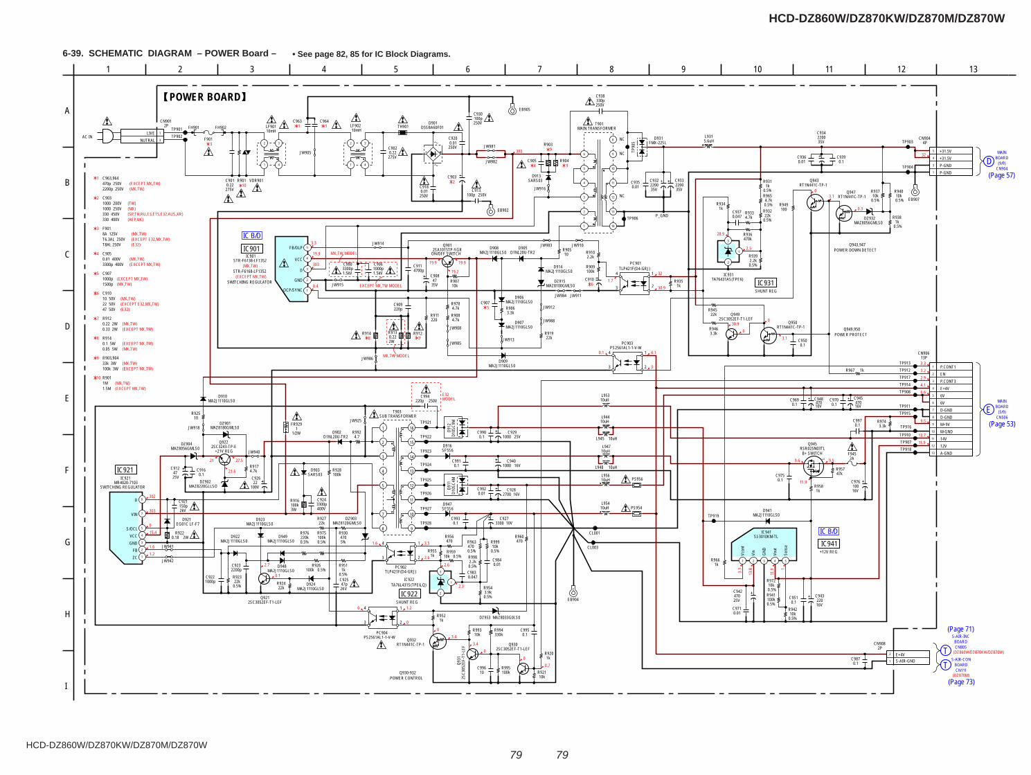
HCD-DZ860W/DZ870KW/DZ870M/DZ870W
HCD-DZ860W/DZ870KW/DZ870M/DZ870W
7979
6-39. SCHEMATIC DIAGRAM – POWER Board – • See page 82, 85 for IC Block Diagrams.
MAIN
(9/9)D BOARD
CN904
(5/9)BOARD
CN506
MAIN
E
T BOARDS-AIR-CON
CN111
T
S-AIR-INCBOARDCN805
IC B/D
IC B/D
303
3.3
19.9
303
0.4
19.9
19.2
19.9
32
30.91.7
0.1 4.1
3
030.9
0
3.1
2.5
28.9
0.3
3.10
9.59.6
11.9
3.3
13.8
11.9 1
2.3
2.6
3.5
2.6
1.6
0 1.2
00
3.43.4
00
0.7
0.1
2.7
1.21.6
15.40
303
302
27.5
21.6
21
32
3.33.22.94.16.6
9.5
13.711.9
6
7
(EXCEPT MX,TW)
5
(MX,TW)
(MX,TW)
4
1
(TW)2
3
3
10
1 1
2
4
9
9
(MX,TW)
(EXCEPT MX,TW)
EXCEPT MX,TW MODEL
MX,TW MODEL
6
5
78
MX,TW MODEL
E32MODEL
(DZ860W/DZ870KW/DZ870W)
(DZ870M)
(MX,TW)
(MX)(SP,TH,RU,E3,E15,E32,AUS,KR)(AEP,UK)
(EXCEPT E32,MX,TW)
(EXCEPT MX,TW)
(EXCEPT MX,TW)(MX,TW)
(EXCEPT E32,MX,TW)(MX,TW)
(E32)
(MX,TW)(EXCEPT MX,TW)
(EXCEPT MX,TW)(MX,TW)
8
(EXCEPT MX,TW)(MX,TW)
9
(EXCEPT MX,TW)(MX,TW)
10
(E32)
10k
CL001
275V0.22C902
TH901 D5SBA60F01D901
250V0.01
C920
250V0.01C918
250V100pC930
250V100pC913
R903
R904
SARS03D913
1
2
3
4
5
STR-F6138-LF1352IC901
STR-F6168-LF1352
OCP/SYNC
GND
D
VCC
FB/OLP
1.5kV
C9061000p
35V47
C9084700pC911
220pC909
220R911
10R905D1NL20U-TR2
D905
3.3kR906
Q901
ON/OFF SWITCH2SA1015TP-YGR
10kR907
C907
2.2kR910
C910
100kR909
PC901TLP421F(D4-GRJ)
35V2200C932
35V2200C933
35V2200C934
0.1C939
470kR936
4.7kR933
0.047C937
3
1
2
TA76431AS(TPE6)IC931
1kR935
RT1N441C-TP-1Q943
RT1N441C-TP-1Q947
10uHL945
10V470
C948
25V470C942
0.1C951
TP901TP902
TP903
TP904
TP911
TP907
TP908TP914
TP918
TP912TP913
1kR967
1kR966
16V470
C945
10uHL947
10uHL948
S
RSR025N03TLQ945
B+ SWITCH
47kR957
1kR958
16V100
C976
3.3kR974
TP915
TP916
TP917
R901
275V0.22C901
F9011
3
CN9012P
LIVENUTRAL
C903
R912R9130.222W
CL003
1.5kV3300pC980
C9051 4
32
LF90110mH
1 4
32
LF90210mH
1
3
10
11
2
9
12
13
14
5
8
4
6
T901MAIN TRANSFORMER
NC
NC
NC
JW905
JW916
JW915
JW912
JW913
JW911
JW910
JW981
JW982
TP919
FH901 FH902
JW983
JW984
JW988
JW986
L94410uH
0.01C936
0.01C971
1 2 3 4 5
SI-3010KM-TLIC941
Vcon
t
Vin
GND
Vout
Sens
e
C9350.01
C964C963
FMX-22SLD931 5.6uH
L931
E EB902
E
EB904
R914
VDR901
100kR928
Q922
+21V REG2SC3243-TP-E
10V3300C927
16V1000C940
1000pC922
3
1
2
TA76L431S(TPE6,Q)IC922
1kR955
D10S
C9M
D912
400V3300pC924
D1NL20U-TR2D902
2200pC923 PC902
TLP421F(D4-GRJ)
25V1000C929
25V47
C912
10R925
16V2700C928
SF5S6D916
4.7kR917
5%470
R930
0.5%22k
R923
0.5%3.9kR954
0.5%2.2kR998
470R956
10kR921
22kR919
0.01C992
SF5S6D947
3W100kR916
2W0.18R922
JW918
2SC3052EF-T1-LEFQ949
RT1N441C-TP-1Q950
22kR945
3.3kR946
4.7R992
JW941
JW940D1
0SC4
MD9
11
250V220pC994
2SC3052EF-T1-LEFQ921
2SC3052EF-T1-LEFQ930
1
3
4
5
CN9044P
P-GNDP-GND+31.5V+31.5V
R975100k0.5%
R976220k0.5%
22kR927
0.5%10k
R999
MA2J1110GLS0D909
MA2J1110GLS0D907
MA2J1110GLS0D914
MA2J1110GLS0D908
MA2J1110GLS0D924
MA2J1110GLS0D923
MA2J1110GLS0D922
MA2J1110GLS0D949
MA2J1110GLS0D948
MA2J1110GLS0D910
MAZ8120GMLS0DZ903
MAZ8100GMLS0DZ915
MA2J1110GLS0D906
100V22
C926
TP910
0.5%2.2kR939
0.5%1k
R931
0.5%4.7k
R965
TP90
5
TP906
TP921
TP922
TP923
TP924
TP925
TP926
TP927
TP928
JW985
PC904PS2561AL1-1-V-W
PC903PS2561AL1-1-V-W
JW914
SARS03D903
JW908
JW925
JW9420.01C984
2kV150pC921
0.5%22k
R932
MAZ8056GMLS0DZ904
MA2J1110GLS0D941
0.5%10k
R972
100kR941
0.5%
10kR942
0.5%
10uHL953
R9521k MAZ8033G0LS0DZ953
470R960
0.5%10k
R937
0.5%10k
R940
0.5%1k
R938MAZ8056GMLS0
DZ932
0.1C950
0.5%10kR959
0.047C983
1
9
7
5
4
3
2
MR4020-7103IC921
ZCFB
GNDVCC
S/OCL
VIN
D
T903SUB TRANSFORMER
22kR924
EG01C LF-F7D921
10uHL956
10uHL954
1/2W
FR9291MAZ8180GMLS0
DZ901
MAZ8220GLLSODZ902
2SC3
052E
F-T1
-LEF
Q931
RT1N441C-TP-1Q932
R993 R994330k
R995100k
C99610
250V330pC938
PS954
PS956
C9950.1
1kR920
0.1C997
0.5%470R963
0.1C990
0.1C991
0.1C993
16V220
C943
0.1C969
0.1C970
C9160.1
E
EB907
0.1C975
C9870.1
1
2
3
4
5
6
7
8
9
10
11
12
13
13PCN906
P.CONT1ENP.CONT3E+4V6V6VD-GNDD-GNDM+9VM-GND14V12VA-GND
2PCN908
S-AIR-GNDE+4V
0.5%100kR926
0.5%1k
R951
1kR934
2KV47p
C925
4.7kR978
4.7kR908
100R949
E EB905
2AF945
P_GND
POWER BOARD
+12V REGIC941
SWITCHING REGULATOR
IC901
SWITCHING REGULATOR
IC921
SHUNT REGIC931
SHUNT REGIC922
4
3
1
2
4
3
1
4
3
1
2
4
3
1
2
2
Q943,947POWER DOWN DETECT
Q949,950POWER PROTECT
Q930-932POWER CONTROL
AC IN
3
F
D
1310
A
8
H
2 114
E
5
I
G
C
6 71 12
B
9
1
2
3
4
5
7
8 9
10
11
12
13
14
15
16
1000 200V
0.01 400V
C903
C963,964
C905
8A 125V
470p 250V
F901
2200p 250V
1000 250V
330 400V330 450V
T6.3AL 250V
3300p 400V
1000p1500p
C907
10 50V22 50V
C910
47 50V
0.33 2W
R9120.22 2W
0.1 5W0.05 5W
R914
33k 3W100k 3W
R903,904
1M1.5M
R901
T8AL 250V
1
2
(Page 57)
(Page 53)
(Page 71)
(Page 73)

HCD-DZ860W/DZ870KW/DZ870M/DZ870W
HCD-DZ860W/DZ870KW/DZ870M/DZ870W
8080
• IC Block Diagrams
IC1201 FAN8036L (MAIN Board (4/9))
IC3003 TC7WH157FK(TE85R) (MAIN Board (7/9))
A/B116
G117
A 1
2
3
A
B
Y5
Y
B
GND 4
VCC8
YEN G
Y
OUT1
IN 1-
FI N(GND)
FI N(GND)
IN2 +
IN 2-
OUT2
R ES1
REGCTL
IN 3+
IN3 -
OUT3
IN 4+
FI N(GND)
IN4-
OUT4 CT
L
FWD
REV
MU
TE12
3
MUTE
4
TSD_
M
PVCC
2
DO5-
DO5+
P G ND2
DO4-
DO4+
DO3-
DO3+
REGO2
REGO1
P GND1
DO2-
DO2+
DO1-
FI N(GND)
DO1+
PVCC
1
REGV
CC
OPOU
T2
OPIN
2-
OPIN
2+
VREF
SVCC
OPOU
T1
OPIN
1-
OPIN
1+
IN1+
SGN
D
REGVCC
RES2
REGVCC
REGVCC REGVCCPS
1
2
3
4
5
6
7
8
9
10
11
12
13 14 15 16 17 18 19 20 21 22 23 24
25
26
27
28
29
30
31
32
33
34
35
36
373839404142434445464748
MUTE123 MUTE4 PS TSD_M
SW
MSC
+
-
TSD
REGVCC
IC3010 CDX9788AR (MAIN Board (9/9))IC3020 CDX9788AR (MAIN Board (9/9)) (DZ870M)IC3030 CDX9788AR (MAIN Board (8/9))
12
11
10
9
8
7
6
5
4
3
VSUBC
XVSS
OUTR2(–)
VSSR
OUTR1(+)
VDDR
VSSL
VSSR
OUTL2(–)
OUTL1(+)
VSSL
VDDL
2
1
PWM
CLOCKGENERATOR
(SECONDARY)
CLOCKGENERATOR(PRIMARY)
31
29
25 OVF FLAGL
26 SFLAG
27 INIT
30S PGAINCONTROL
INIT/MUTE
SAMPLINGRATE
CONVERTER
FILTER &LOW CUT
FILTER
LINERINTERPOLATORΔ Σ
48
XFSO
IN
47
XVDD
HPVD
DL
46 45
HPOU
TL1
HPVS
SL
44 43
HPOU
TL2
HPVD
DR
42 41
HPOU
TR1
HPVS
SR
40
HPOU
TR2
39 37
FSOC
KO
38
FSOI
13
XOVS
S
14
XFSO
OUT
15
XOVD
D
16
DVDD
17
DVSS
18
NSPM
UTE
19
SOFT
MUTE
20
PGMU
TE
SERIALCONTROLLER
21
SCDT
22
SCSH
IFT
23
SCLA
TCH
24
OVF
FLAG
R
28 MCKSEL
32 BFVDD
33 BFVSS
34 TEST
35 DVDD
36 XFSIIN
LRCKBCKDATA
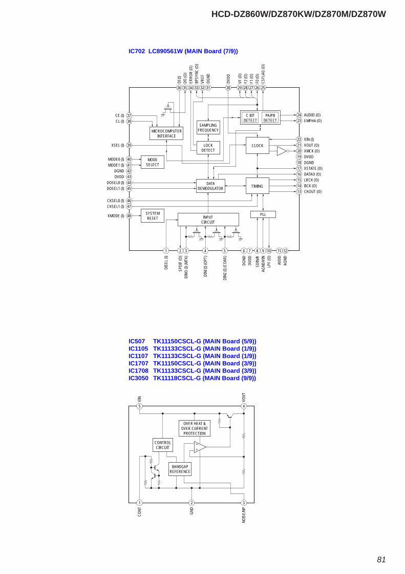
HCD-DZ860W/DZ870KW/DZ870M/DZ870W
81
IC702 LC890561W (MAIN Board (7/9))
3837
36
2324
1 2 3 4 5
44
8 9 10
46
17
222120
3035 2526272829323334
16
45131415
47
4041
48
CL (I)
39XSEL (I)
CE (I)
DI (I
)
EMPHA (O)AUDIO (O)
DISE
L (I)
SPDI
F (O
)DI
NO (I
) (MT
K)
DINI
(I) (
OPT)
DIN2
(I) (
COAX
)
6DG
ND7
DVDD
11
AVDD
12
AGND
DOSEL0 (I)
SDIN
/RAG
ND/V
INLP
F (O
)
CKSEL0 (I)
XSTATE (O)18 DGND19 DVDD
XIN (I)XOUT (O)XMCK (O)
DVDD
31
DGND
DO (O
)
CSFL
AG (O
)F0
(O)
F1 (O
)F2
(O)
VF (O
)
VREF
BPSY
NC (O
)ER
ROR
(O)
DATAO (O)
DOSEL1 (I)CKOUT (O)BCK (O)LRCK (O)
CKSEL1 (I)
MODE0 (I)MODE1 (I)
42DGND43DVDD
XMODE (I)
TIMING
MICROCOMPUTERINTERFACE
SAMPLINGFREQUENCY
C BITDETECT
PA/PBDETECT
LOCKDETECT
SYSTEMRESET
MODESELECT
INPUTCIRCUIT
DATADEMODULATOR
PLL
CLOCK
IC507 TK11150CSCL-G (MAIN Board (5/9))IC1105 TK11133CSCL-G (MAIN Board (1/9))IC1107 TK11133CSCL-G (MAIN Board (1/9))IC1707 TK11150CSCL-G (MAIN Board (3/9))IC1708 TK11133CSCL-G (MAIN Board (3/9))IC3050 TK11118CSCL-G (MAIN Board (9/9))
1 2 3
5 4
CONT
GND
NOIS
E/NP
VIN
VOUT
CONTROLCIRCUIT
OVER HEAT &OVER CURRENT
PROTECTION
BANDGAPREFERENCE

HCD-DZ860W/DZ870KW/DZ870M/DZ870W
82
IC201 SI-3010KM-TL (MAIN Board (6/9))IC504 SI-3010KM-TL (MAIN Board (5/9))IC505 SI-3010KM-TL (MAIN Board (5/9))IC506 SI-3010KM-TL (MAIN Board (5/9))IC941 SI-3010KM-TL (POWER Board)
TSD
REF
4 3 2 15
+–
VOUT
GND
VIN
VCON
T
SENS
E
IC707 PCM1808PWR (MAIN Board (7/9))IC805 PCM1808PWR (S-AIR-INC Board)
DELTA-SIGMAMODULATOR
DELTA-SIGMAMODULATOR
ANTIALIASLOW-PASS FILTER
ANTIALIASLOW-PASS FILTER
AGNDAVCC
23
VDDDGND
45
LRCK 7
REFERENCE
× 1/64DECIMATION
FILTERWITH
HIGH-PASSFILTER
SERIALINTERFACE
&MODE/FORMAT
CONTROL
FMT12
VINR14
VINL13
MD111MD010DOUT9BCK8
CLOCK & TIMING CONTROL
POWERSUPPLY
SCKI 6
VREF 1
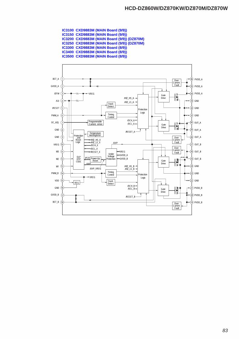
HCD-DZ860W/DZ870KW/DZ870M/DZ870W
83
IC3100 CXD9883M (MAIN Board (9/9))IC3150 CXD9883M (MAIN Board (9/9))IC3200 CXD9883M (MAIN Board (9/9)) (DZ870M)IC3250 CXD9883M (MAIN Board (9/9)) (DZ870M)IC3300 CXD9883M (MAIN Board (8/9))IC3400 CXD9883M (MAIN Board (8/9))IC3500 CXD9883M (MAIN Board (8/9))
1
10
9
8
11
12
13
14
7
6
15
16
17
18
3
4
5
20
19
2
GND
GND
GND
GND
GND
GND
36
35
34
33
32
31
30
29
28
27
26
25
24
23
22
21
StuckDetect
StuckDetect
TimingControl
TimingControl Protection
Logic
ProtectionLogic
GateDrive
GateDrive
GateDrive
GateDrive
OverCurrent
Fault
OverCurrent
Fault
OverCurrent
Fault
OverCurrent
Fault
ProgrammableCurrent sense
OUT_B
OUT_B
OUT_B
PVDD_B
PVDD_B
PVDD_B
OUT_A
OUT_A
OUT_A
PVDD_A
PVDD_A
PVDD_A
REG
Protectionand
ResetLogic
OLPOTPCB3C
Temperaturewaming/error
Power-UpReset
UnderVoltage
Protection
/HIZ_HS_B
/HIZ_HS_A
/HIZ_LS_B
/HIZ_LS_A
/OCL_B
/OCL_A
/OCH_B
/OCH_A
/RESET_A
/RESET_B
VREG
/HIZ_HS_X/HIZ_LS_X/OCH_X/OCL_X/RESET_X
/PCR
/UVP
/UVP
/UVP_VREG
VREGGVDD_AGVDD_B
VREG
GND
GND
GND
BST_B
GVDD_B
VDD
PWM_B
M1
M2
M3
VREG
OC_ADJ
PWM_A
/RESET
/SD
/DTW
GVDD_A
BST_A
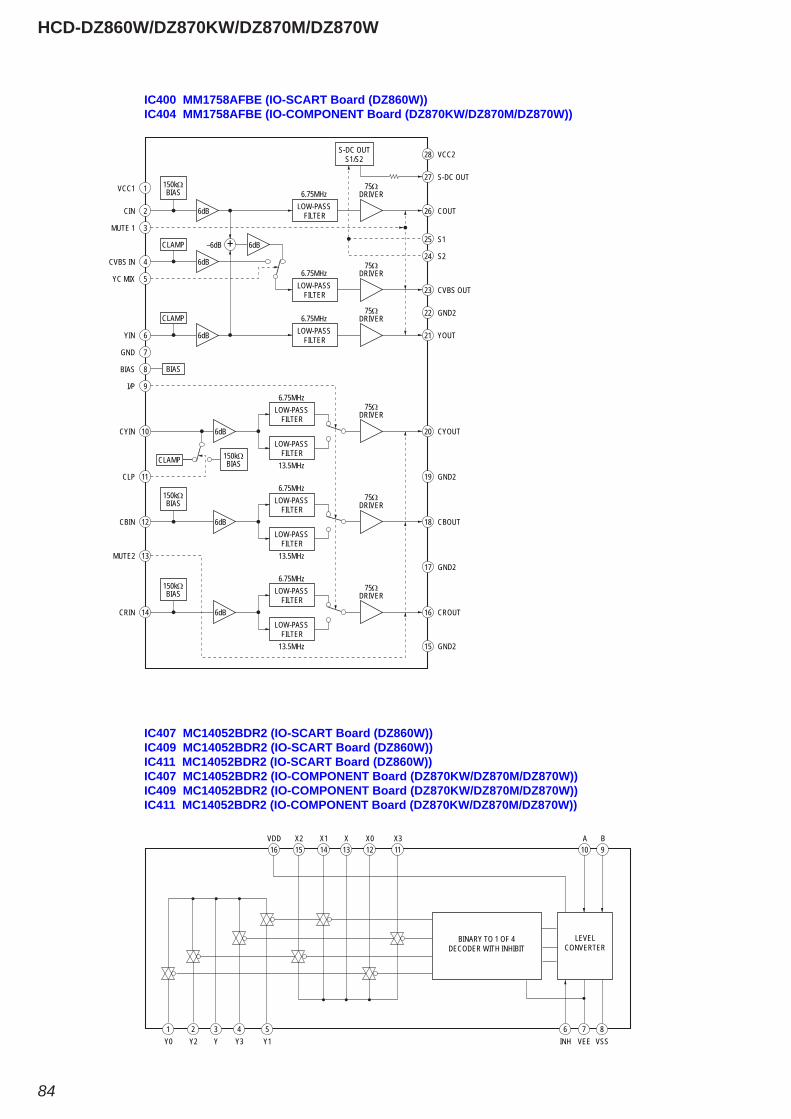
HCD-DZ860W/DZ870KW/DZ870M/DZ870W
84
IC400 MM1758AFBE (IO-SCART Board (DZ860W))IC404 MM1758AFBE (IO-COMPONENT Board (DZ870KW/DZ870M/DZ870W))
1
2
3
4
28 VCC2
23 CVBS OUT
25 S1
150kΩBIAS
12
150kΩBIAS
CLAMP
6dB
6dB
6
7
8
CLAMP
BIAS
6dB
9
10
11
13
5
+ 6dB–6dB
6dB
27 S-DC OUT
24 S2
LOW-PASSFILTER
21 YOUT
22 GND2
6.75MHz75Ω
DRIVER
LOW-PASSFILTER
6.75MHz75Ω
DRIVER
20 CYOUT
75ΩDRIVER
S-DC OUTS1/S2
26 COUTLOW-PASSFILTER
6.75MHz75Ω
DRIVER
CLAMP 150kΩBIAS
LOW-PASSFILTER
6.75MHz
LOW-PASSFILTER
13.5MHz
18 CBOUT
19 GND2
17 GND2
15 GND2
75ΩDRIVERLOW-PASS
FILTER
6.75MHz
LOW-PASSFILTER
13.5MHz
14
150kΩBIAS
16 CROUT
75ΩDRIVERLOW-PASS
FILTER
6.75MHz
LOW-PASSFILTER
13.5MHz
6dB
6dB
VCC1
CIN
MUTE 1
CVBS IN
CBIN
YIN
GND
BIAS
I/P
CYIN
CLP
MUTE2
YC MIX
CRIN
IC407 MC14052BDR2 (IO-SCART Board (DZ860W))IC409 MC14052BDR2 (IO-SCART Board (DZ860W))IC411 MC14052BDR2 (IO-SCART Board (DZ860W))IC407 MC14052BDR2 (IO-COMPONENT Board (DZ870KW/DZ870M/DZ870W))IC409 MC14052BDR2 (IO-COMPONENT Board (DZ870KW/DZ870M/DZ870W))IC411 MC14052BDR2 (IO-COMPONENT Board (DZ870KW/DZ870M/DZ870W))
1Y0
2Y2
3Y
4Y3
5Y1
15X2
14X1
13X
12X0
11X3
10A
9B
16VDD
6INH
7VEE
8VSS
BINARY TO 1 OF 4DECODER WITH INHIBIT
LEVELCONVERTER
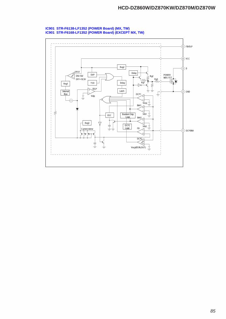
HCD-DZ860W/DZ870KW/DZ870M/DZ870W
85
IC901 STR-F6138-LF1352 (POWER Board) (MX, TW)IC901 STR-F6168-LF1352 (POWER Board) (EXCEPT MX, TW)
OCP/INH1
GND2
D3
VCC4
FB/OLP5
+–
+–
+–
+–
+–
Delay
OVP
TSD
Delay
Reg2
Reg1
Reg3
Current mirror
POWERMOS FET
Latch
OSC Boottom SkipLogic
OCP2Logic
InternalBias OCP1
Vocp
Rg3Rg2
Rg1
OCP2
+–
UVL0
ON=16VOFF=10.5V
INH1
INH2
FB
Vth1
+–
IOLP
Volp
Vth2
Vocp(BSIN,OUT)
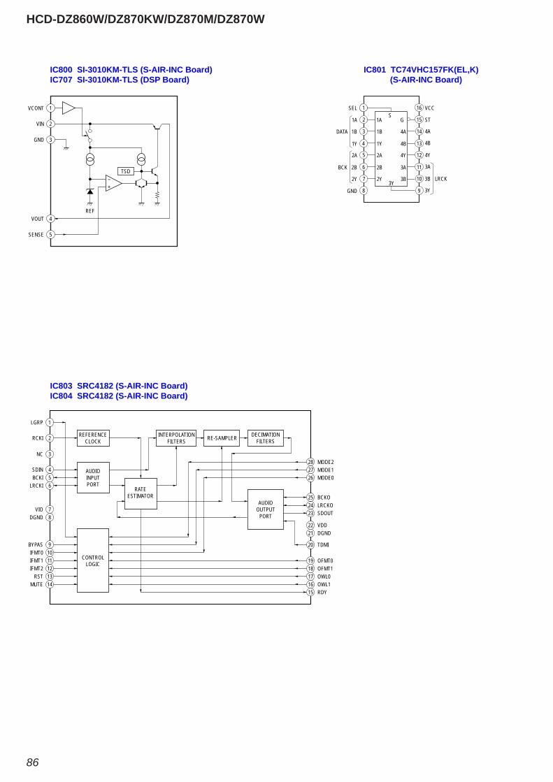
HCD-DZ860W/DZ870KW/DZ870M/DZ870W
86
IC800 SI-3010KM-TLS (S-AIR-INC Board)IC707 SI-3010KM-TLS (DSP Board)
IC803 SRC4182 (S-AIR-INC Board)IC804 SRC4182 (S-AIR-INC Board)
IC801 TC74VHC157FK(EL,K) (S-AIR-INC Board)
1VCONT
TSD
2VIN
3GND
4VOUT
5SENSE
+–
REF
SEL 111
1A 2
3
4
5
6
7
DATA
BCK
1A
1B
1Y
2A
2B
2Y
1B
1Y
2A
2B
2Y
GND 8
VCC
ST
16
4A
15
14
13
1112
11
10 LRCK
G
4B
4Y
3A
4A
4B
4Y
3A
3B
9
3B
3Y3Y
S
1LGRP
18 OFMT117 OWL016 OWL1
20 TDMI
19 OFMT0
24 LRCKO23 SDOUT
26 MODE0
25 BCKO
28 MODE227 MODE1
22 VDD21 DGND
15 RDY
2RCKI
3NC
4SDIN5BCKI6LRCKI
9BYPAS10IFMT011IFMT112IFMT213RST14MUTE
7VIO8DGND
REFERENCECLOCK
INTERPOLATIONFILTERS RE-SAMPLER DECIMATION
FILTERS
AUDIOOUTPUT
PORT
AUDIOINPUTPORT
RATEESTIMATOR
CONTROLLOGIC
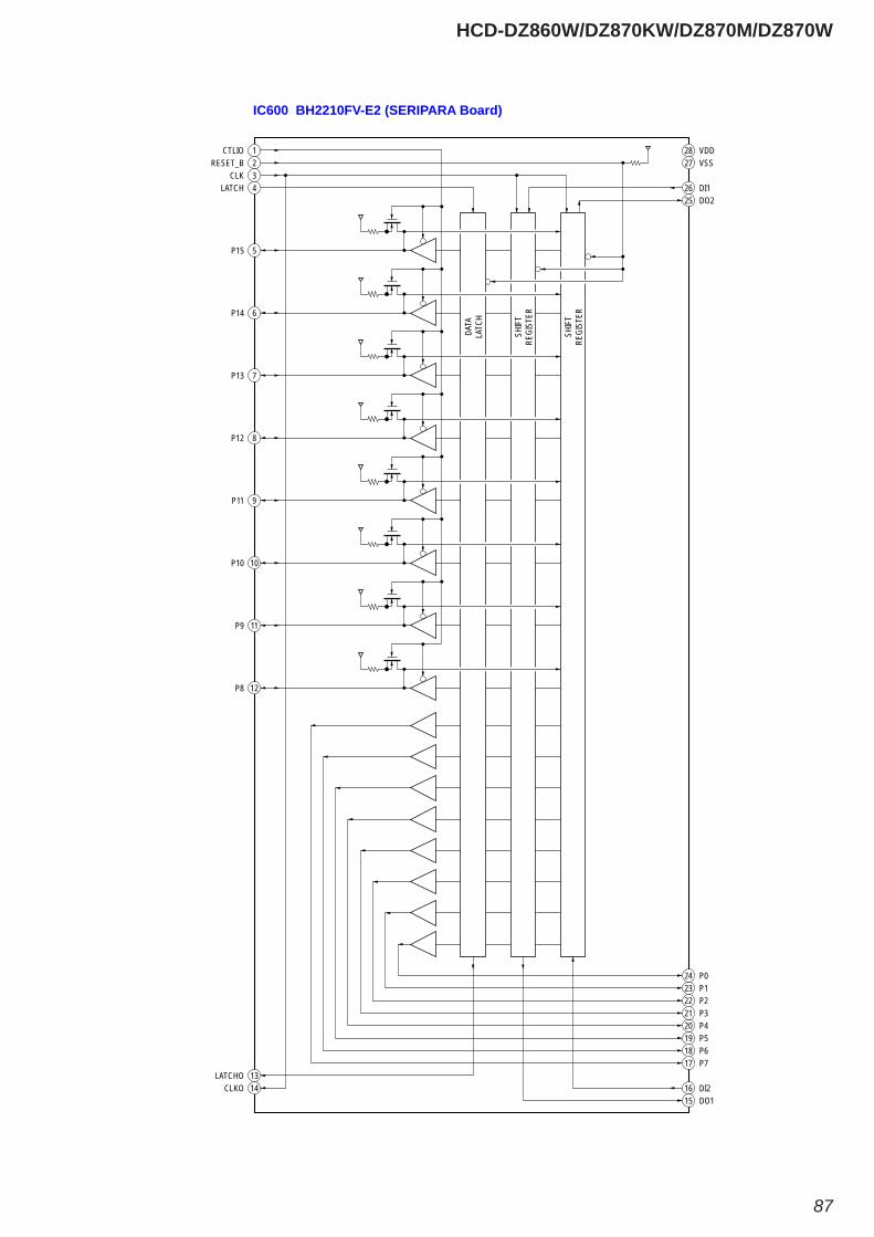
HCD-DZ860W/DZ870KW/DZ870M/DZ870W
87
IC600 BH2210FV-E2 (SERIPARA Board)
DATA
LATC
H
1CTLIO2RESET_B3CLK4LATCH
5P15
6P14
7P13
8P12
9P11
10P10
11P9
12P8
13LATCHO14CLKO
27 VSS
26 DI125 DO2
28 VDD
17 P718 P619 P520 P421 P322 P223 P124 P0
16 DI215 DO1
SHIF
TRE
GIST
ER
SHIF
TRE
GIST
ER
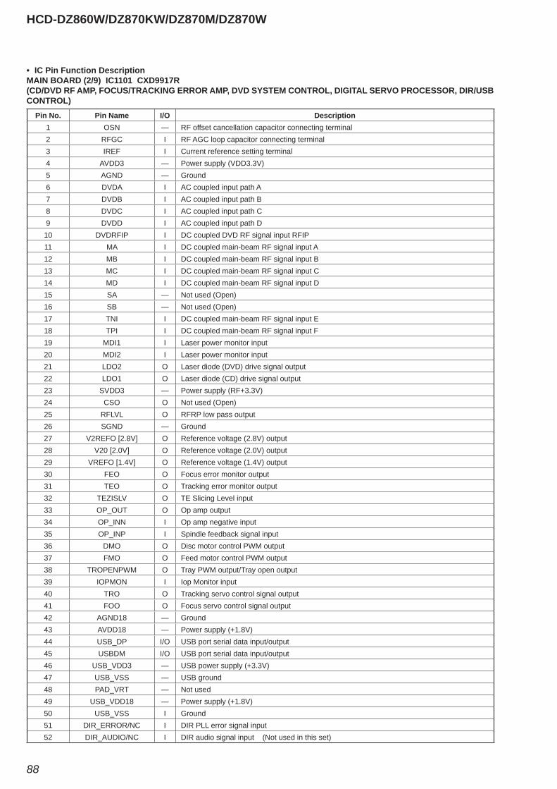
HCD-DZ860W/DZ870KW/DZ870M/DZ870W
88
• IC Pin Function DescriptionMAIN BOARD (2/9) IC1101 CXD9917R(CD/DVD RF AMP, FOCUS/TRACKING ERROR AMP, DVD SYSTEM CONTROL, DIGITAL SERVO PROCESSOR, DIR/USB CONTROL)
Pin No. Pin Name I/O Description1 OSN — RF offset cancellation capacitor connecting terminal2 RFGC I RF AGC loop capacitor connecting terminal3 IREF I Current reference setting terminal4 AVDD3 — Power supply (VDD3.3V)5 AGND — Ground6 DVDA I AC coupled input path A7 DVDB I AC coupled input path B8 DVDC I AC coupled input path C9 DVDD I AC coupled input path D10 DVDRFIP I DC coupled DVD RF signal input RFIP11 MA I DC coupled main-beam RF signal input A12 MB I DC coupled main-beam RF signal input B13 MC I DC coupled main-beam RF signal input C14 MD I DC coupled main-beam RF signal input D15 SA — Not used (Open)16 SB — Not used (Open)17 TNI I DC coupled main-beam RF signal input E18 TPI I DC coupled main-beam RF signal input F19 MDI1 I Laser power monitor input20 MDI2 I Laser power monitor input21 LDO2 O Laser diode (DVD) drive signal output22 LDO1 O Laser diode (CD) drive signal output23 SVDD3 — Power supply (RF+3.3V)24 CSO O Not used (Open)25 RFLVL O RFRP low pass output26 SGND — Ground27 V2REFO [2.8V] O Reference voltage (2.8V) output28 V20 [2.0V] O Reference voltage (2.0V) output29 VREFO [1.4V] O Reference voltage (1.4V) output30 FEO O Focus error monitor output31 TEO O Tracking error monitor output32 TEZISLV O TE Slicing Level input33 OP_OUT O Op amp output34 OP_INN I Op amp negative input35 OP_INP I Spindle feedback signal input36 DMO O Disc motor control PWM output37 FMO O Feed motor control PWM output38 TROPENPWM O Tray PWM output/Tray open output39 IOPMON I Iop Monitor input40 TRO O Tracking servo control signal output41 FOO O Focus servo control signal output42 AGND18 — Ground43 AVDD18 — Power supply (+1.8V)44 USB_DP I/O USB port serial data input/output45 USBDM I/O USB port serial data input/output46 USB_VDD3 — USB power supply (+3.3V)47 USB_VSS — USB ground48 PAD_VRT — Not used49 USB_VDD18 — Power supply (+1.8V)50 USB_VSS I Ground51 DIR_ERROR/NC I DIR PLL error signal input52 DIR_AUDIO/NC I DIR audio signal input (Not used in this set)
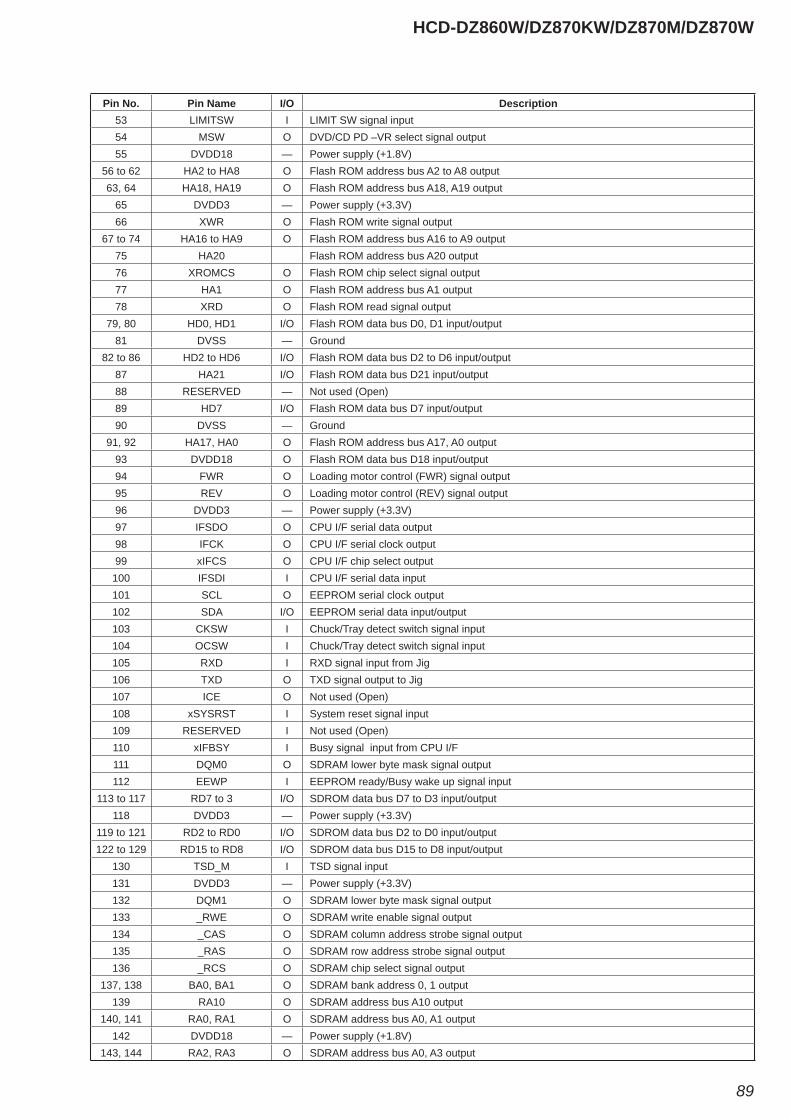
HCD-DZ860W/DZ870KW/DZ870M/DZ870W
89
Pin No. Pin Name I/O Description53 LIMITSW I LIMIT SW signal input54 MSW O DVD/CD PD –VR select signal output55 DVDD18 — Power supply (+1.8V)
56 to 62 HA2 to HA8 O Flash ROM address bus A2 to A8 output63, 64 HA18, HA19 O Flash ROM address bus A18, A19 output
65 DVDD3 — Power supply (+3.3V)66 XWR O Flash ROM write signal output
67 to 74 HA16 to HA9 O Flash ROM address bus A16 to A9 output75 HA20 Flash ROM address bus A20 output76 XROMCS O Flash ROM chip select signal output77 HA1 O Flash ROM address bus A1 output78 XRD O Flash ROM read signal output
79, 80 HD0, HD1 I/O Flash ROM data bus D0, D1 input/output81 DVSS — Ground
82 to 86 HD2 to HD6 I/O Flash ROM data bus D2 to D6 input/output87 HA21 I/O Flash ROM data bus D21 input/output88 RESERVED — Not used (Open)89 HD7 I/O Flash ROM data bus D7 input/output90 DVSS — Ground
91, 92 HA17, HA0 O Flash ROM address bus A17, A0 output93 DVDD18 O Flash ROM data bus D18 input/output94 FWR O Loading motor control (FWR) signal output95 REV O Loading motor control (REV) signal output96 DVDD3 — Power supply (+3.3V)97 IFSDO O CPU I/F serial data output98 IFCK O CPU I/F serial clock output99 xIFCS O CPU I/F chip select output100 IFSDI I CPU I/F serial data input101 SCL O EEPROM serial clock output102 SDA I/O EEPROM serial data input/output103 CKSW I Chuck/Tray detect switch signal input104 OCSW I Chuck/Tray detect switch signal input105 RXD I RXD signal input from Jig106 TXD O TXD signal output to Jig107 ICE O Not used (Open)108 xSYSRST I System reset signal input109 RESERVED I Not used (Open)110 xIFBSY I Busy signal input from CPU I/F111 DQM0 O SDRAM lower byte mask signal output112 EEWP I EEPROM ready/Busy wake up signal input
113 to 117 RD7 to 3 I/O SDROM data bus D7 to D3 input/output118 DVDD3 — Power supply (+3.3V)
119 to 121 RD2 to RD0 I/O SDROM data bus D2 to D0 input/output122 to 129 RD15 to RD8 I/O SDROM data bus D15 to D8 input/output
130 TSD_M I TSD signal input131 DVDD3 — Power supply (+3.3V)132 DQM1 O SDRAM lower byte mask signal output133 _RWE O SDRAM write enable signal output134 _CAS O SDRAM column address strobe signal output135 _RAS O SDRAM row address strobe signal output136 _RCS O SDRAM chip select signal output
137, 138 BA0, BA1 O SDRAM bank address 0, 1 output139 RA10 O SDRAM address bus A10 output
140, 141 RA0, RA1 O SDRAM address bus A0, A1 output142 DVDD18 — Power supply (+1.8V)
143, 144 RA2, RA3 O SDRAM address bus A0, A3 output
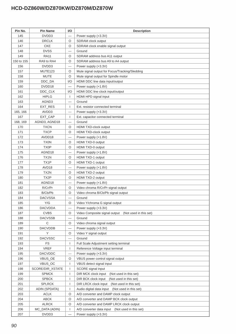
HCD-DZ860W/DZ870KW/DZ870M/DZ870W
90
Pin No. Pin Name I/O Description145 DVDD3 — Power supply (+3.3V)146 DRCLK O SDRAM clock output147 CKE O SDRAM clock enable signal output148 DVSS — Ground149 RA11 O SDRAM address bus A11 output
150 to 155 RA9 to RA4 O SDRAM address bus A9 to A4 output156 DVDD3 — Power supply (+3.3V)157 MUTE123 O Mute signal output for Focus/Tracking/Sledding158 MUTE O Mute signal output for Spindle motor159 DDC_DA I/O HDMI DDC line data input/output160 DVDD18 — Power supply (+1.8V)161 DDC_CLK I/O HDMI DDC line clock input/output162 HIPLG I HDMI HPD signal input163 AGND3 — Ground164 EXT_RES I Ext. resistor connected terminal
165, 166 AVDD3 — Power supply (+3.3V)167 EXT_CAP I Ext. capacitor connected terminal
168, 169 AGND3, AGND18 — Ground170 TXCN O HDMI TXD-clock output171 TXCP O HDMI TXD-clock output172 AVDD18 — Power supply (+1.8V)173 TX0N O HDMI TXD-0 output174 TX0P O HDMI TXD-0 output175 AGND18 — Power supply (+1.8V)176 TX1N O HDMI TXD-1 output177 TX1P O HDMI TXD-1 output178 AVD18 — Power supply (+1.8V)179 TX2N O HDMI TXD-2 output180 TX2P O HDMI TXD-2 output181 AGND18 — Power supply (+1.8V)182 R/Cr/Pr O Video chroma R/Cr/Pr signal output183 B/Cb/Pb O Video chroma B/Cb/Pb signal output184 DACVSSA — Ground185 Y/G O Video Y/chroma G signal output186 DACVDDA — Power supply (+3.3V)187 CVBS O Video Composite signal output (Not used in this set)188 DACVSSB — Ground189 C O Video chroma signal output190 DACVDDB — Power supply (+3.3V)191 Y O Video Y signal output192 DACVSSC — Ground193 FS I Full Scale Adjustment setting terminal194 VREF I Reference Voltage input terminal195 DACVDDC — Power supply (+3.3V)196 VBUS_OE O VBUS power control signal output197 VBUS_OC I VBUS detect signal input198 SCORE/DIR_XSTATE I SCORE signal input199 SPMCK I DIR MCK clock input (Not used in this set)200 SPBCK I DIR BCK clock input (Not used in this set)201 SPLRCK I DIR LRCK clock input (Not used in this set)202 ADIN (SPDATA) I Audio digital data input (Not used in this set)203 ACLK O A/D converter and DAMP clock output204 ABCK O A/D converter and DAMP BCK clock output205 ALRCK O A/D converter and DAMP LRCK clock output206 MC_DATA (ADIN) I A/D converter data input (Not used in this set)207 DVDD3 — Power supply (+3.3V)
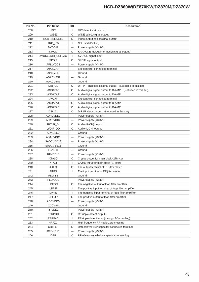
HCD-DZ860W/DZ870KW/DZ870M/DZ870W
91
Pin No. Pin Name I/O Description208 MIC I MIC detect status input209 WIDE O WIDE select signal output210 RGB_SEL/DSEL O Video output select signal output211 TRG_SW I Not used (Pull up)212 DVDD18 — Power supply (+3.3V)213 KMOD O KARAOKE MODE information signal output214 XVOICE/DIR_CSFLAG I XVOICE signal input215 SPDIF O SPDIF signal output216 APLLVDD3 — Power supply (+3.3V)217 APLLCAP — Ext capacitor connected terminal218 APLLVSS — Ground219 ADACVSS2 — Ground220 ADACVSS1 — Ground221 DIR_CE O DIR I/F chip select signal output (Not used in this set)222 ASDATA3 O Audio digital signal output to D-AMP (Not used in this set)223 ASDATA2 O Audio digital signal output to D-AMP 224 AVCM — Ext capacitor connected terminal225 ASDATA1 O Audio digital signal output to D-AMP 226 ASDATA0 O Audio digital signal output to D-AMP 227 DIR_CL O DIR I/F clock output (Not used in this set)228 ADACVDD1 — Power supply (+3.3V)229 ADACVDD2 — Power supply (+3.3V)230 Rt/DIR_DI O Audio (R-CH) output231 Lt/DIR_DO O Audio (L-CH) output232 ADACSS3 — Ground233 ADACVDD3 — Power supply (+3.3V)234 SADCVDD18 — Power supply (+1.8V)235 SADCVSS18 — Ground236 FGND18 — Ground237 RFVDD18 — Power supply (+1.8V)238 XTALO O Crystal output for main clock (27MHz)239 XTALI I Crystal input for main clock (27MHz)240 JITFO O The output terminal of RF jitter meter241 JITFN I The input terminal of RF jitter meter242 PLLVSS — Ground243 PLLVDD3 — Power supply (+3.3V)244 LPFON O The negative output of loop fi lter amplifi er245 LPFIP I The positive input terminal of loop fi lter amplifi er246 LPFIN I The negative input terminal of loop fi lter amplifi er247 LPFOP O The positive output of loop fi lter amplifi er248 ADCVDD3 — Power supply (+3.3V)249 ADCVSS — Ground250 RFVDD3 — Power supply (+3.3V)251 RFRPDC O RF ripple detect output252 RFRPAC I RF ripple detect input (through AC-coupling)253 HRFZC I High frequency RF ripple zero crossing254 CRTPLP O Defect level fi lter capacitor connected terminal255 RFGND18 — Power supply (+3.3V)256 OSP O RF offset cancellation capacitor connecting
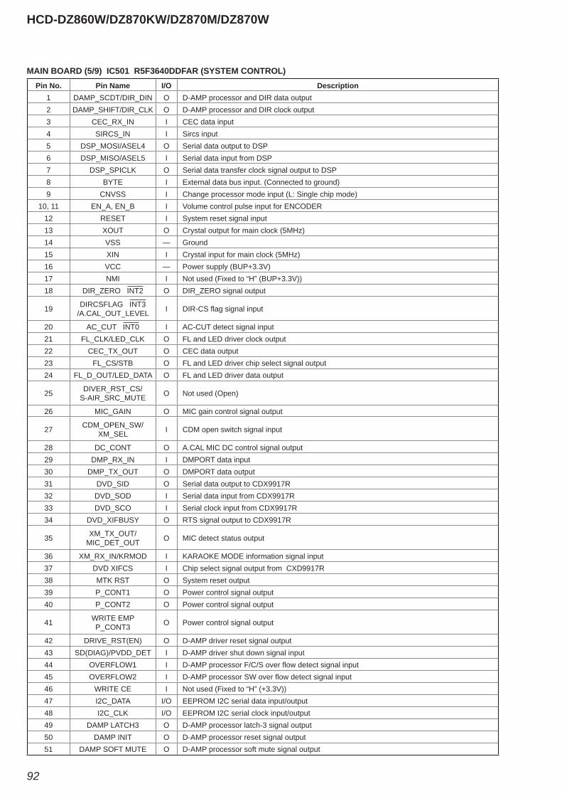
HCD-DZ860W/DZ870KW/DZ870M/DZ870W
92
Pin No. Pin Name I/O Description1 DAMP_SCDT/DIR_DIN O D-AMP processor and DIR data output2 DAMP_SHIFT/DIR_CLK O D-AMP processor and DIR clock output3 CEC_RX_IN I CEC data input4 SIRCS_IN I Sircs input5 DSP_MOSI/ASEL4 O Serial data output to DSP6 DSP_MISO/ASEL5 I Serial data input from DSP7 DSP_SPICLK O Serial data transfer clock signal output to DSP8 BYTE I External data bus input. (Connected to ground)9 CNVSS I Change processor mode input (L: Single chip mode)
10, 11 EN_A, EN_B I Volume control pulse input for ENCODER 12 RESET I System reset signal input13 XOUT O Crystal output for main clock (5MHz)14 VSS — Ground15 XIN I Crystal input for main clock (5MHz)16 VCC — Power supply (BUP+3.3V)17 NMI I Not used (Fixed to “H” (BUP+3.3V))18 DIR_ZERO INT2 O DIR_ZERO signal output
19 DIRCSFLAG INT3/A.CAL_OUT_LEVEL I DIR-CS fl ag signal input
20 AC_CUT INT0 I AC-CUT detect signal input21 FL_CLK/LED_CLK O FL and LED driver clock output22 CEC_TX_OUT O CEC data output23 FL_CS/STB O FL and LED driver chip select signal output24 FL_D_OUT/LED_DATA O FL and LED driver data output
25 DIVER_RST_CS/S-AIR_SRC_MUTE O Not used (Open)
26 MIC_GAIN O MIC gain control signal output
27 CDM_OPEN_SW/XM_SEL I CDM open switch signal input
28 DC_CONT O A.CAL MIC DC control signal output29 DMP_RX_IN I DMPORT data input 30 DMP_TX_OUT O DMPORT data output 31 DVD_SID O Serial data output to CDX9917R32 DVD_SOD I Serial data input from CDX9917R33 DVD_SCO I Serial clock input from CDX9917R34 DVD_XIFBUSY O RTS signal output to CDX9917R
35 XM_TX_OUT/MIC_DET_OUT O MIC detect status output
36 XM_RX_IN/KRMOD I KARAOKE MODE information signal input37 DVD XIFCS I Chip select signal output from CXD9917R38 MTK RST O System reset output39 P_CONT1 O Power control signal output40 P_CONT2 O Power control signal output
41 WRITE EMPP_CONT3 O Power control signal output
42 DRIVE_RST(EN) O D-AMP driver reset signal output43 SD(DIAG)/PVDD_DET I D-AMP driver shut down signal input44 OVERFLOW1 I D-AMP processor F/C/S over fl ow detect signal input45 OVERFLOW2 I D-AMP processor SW over fl ow detect signal input46 WRITE CE I Not used (Fixed to “H” (+3.3V))47 I2C_DATA I/O EEPROM I2C serial data input/output48 I2C_CLK I/O EEPROM I2C serial clock input/output49 DAMP LATCH3 O D-AMP processor latch-3 signal output50 DAMP INIT O D-AMP processor reset signal output51 DAMP SOFT MUTE O D-AMP processor soft mute signal output
MAIN BOARD (5/9) IC501 R5F3640DDFAR (SYSTEM CONTROL)
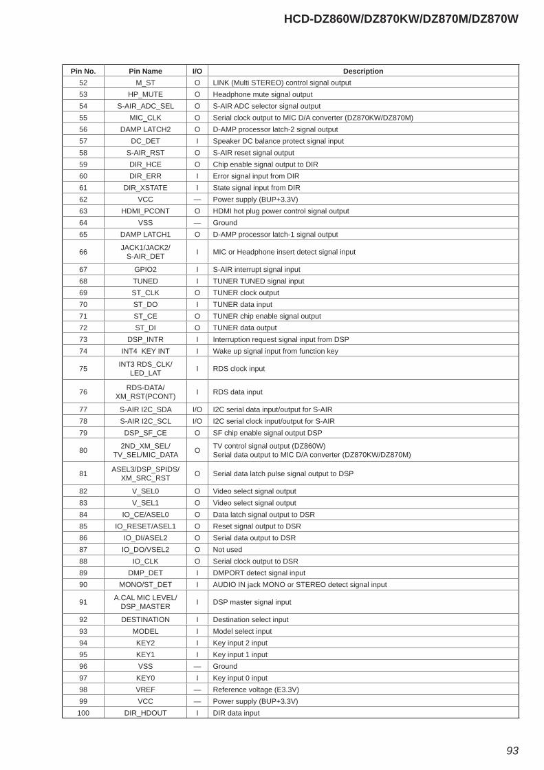
HCD-DZ860W/DZ870KW/DZ870M/DZ870W
93
Pin No. Pin Name I/O Description52 M_ST O LINK (Multi STEREO) control signal output53 HP_MUTE O Headphone mute signal output54 S-AIR_ADC_SEL O S-AIR ADC selector signal output55 MIC_CLK O Serial clock output to MIC D/A converter (DZ870KW/DZ870M)56 DAMP LATCH2 O D-AMP processor latch-2 signal output57 DC_DET I Speaker DC balance protect signal input58 S-AIR_RST O S-AIR reset signal output59 DIR_HCE O Chip enable signal output to DIR60 DIR_ERR I Error signal input from DIR61 DIR_XSTATE I State signal input from DIR62 VCC — Power supply (BUP+3.3V)63 HDMI_PCONT O HDMI hot plug power control signal output64 VSS — Ground65 DAMP LATCH1 O D-AMP processor latch-1 signal output
66 JACK1/JACK2/S-AIR_DET I MIC or Headphone insert detect signal input
67 GPIO2 I S-AIR interrupt signal input68 TUNED I TUNER TUNED signal input69 ST_CLK O TUNER clock output70 ST_DO I TUNER data input71 ST_CE O TUNER chip enable signal output72 ST_DI O TUNER data output73 DSP_INTR I Interruption request signal input from DSP74 INT4 KEY INT I Wake up signal input from function key
75 INT3 RDS_CLK/LED_LAT I RDS clock input
76 RDS-DATA/XM_RST(PCONT) I RDS data input
77 S-AIR I2C_SDA I/O I2C serial data input/output for S-AIR78 S-AIR I2C_SCL I/O I2C serial clock input/output for S-AIR79 DSP_SF_CE O SF chip enable signal output DSP
80 2ND_XM_SEL/TV_SEL/MIC_DATA O TV control signal output (DZ860W)
Serial data output to MIC D/A converter (DZ870KW/DZ870M)
81 ASEL3/DSP_SPIDS/XM_SRC_RST O Serial data latch pulse signal output to DSP
82 V_SEL0 O Video select signal output83 V_SEL1 O Video select signal output84 IO_CE/ASEL0 O Data latch signal output to DSR85 IO_RESET/ASEL1 O Reset signal output to DSR86 IO_DI/ASEL2 O Serial data output to DSR87 IO_DO/VSEL2 O Not used88 IO_CLK O Serial clock output to DSR89 DMP_DET I DMPORT detect signal input90 MONO/ST_DET I AUDIO IN jack MONO or STEREO detect signal input
91 A.CAL MIC LEVEL/DSP_MASTER I DSP master signal input
92 DESTINATION I Destination select input93 MODEL I Model select input94 KEY2 I Key input 2 input95 KEY1 I Key input 1 input96 VSS — Ground97 KEY0 I Key input 0 input98 VREF — Reference voltage (E3.3V)99 VCC — Power supply (BUP+3.3V)100 DIR_HDOUT I DIR data input
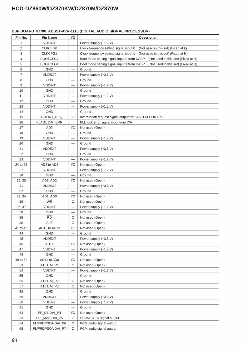
HCD-DZ860W/DZ870KW/DZ870M/DZ870W
94
Pin No. Pin Name I/O Description1 VDDINT — Power supply (+1.2 V)2 CLKCFG0 I Clock frequency setting signal input 0 (Not used in this set) (Fixed at L)3 CLKCFG1 I Clock frequency setting signal input 1 (Not used in this set) (Fixed at H)4 BOOTCFG0 I Boot mode setting signal input 0 from DASP (Not used in this set) (Fixed at H)5 BOOTCFG1 I Boot mode setting signal input 1 from DASP (Not used in this set) (Fixed at H)6 GND — Ground7 VDDEXT — Power supply (+3.3 V)8 GND — Ground9 VDDINT — Power supply (+1.2 V)10 GND — Ground11 VDDINT — Power supply (+1.2 V)12 GND — Ground13 VDDINT — Power supply (+1.2 V)14 GND — Ground15 FLAG0 INT_REQ O Interruption request signal output for SYSTEM CONTROL16 FLAG1 DIR_ERR I PLL lock error signal input from DIR17 AD7 I/O Not used (Open)18 GND — Ground19 VDDINT — Power supply (+1.2 V)20 GND — Ground21 VDDEXT — Power supply (+3.3 V)22 GND — Ground23 VDDINT — Power supply (+1.2 V)
24 to 26 AD6 to AD4 I/O Not used (Open)27 VDDINT — Power supply (+1.2 V)28 GND — Ground
29, 30 AD3, AD2 I/O Not used (Open)31 VDDEXT — Power supply (+3.3 V)32 GND — Ground
33, 34 AD1, AD0 I/O Not used (Open)35 WR O Not used (Open)
36, 37 VDDINT — Power supply (+1.2 V)38 GND — Ground39 RD O Not used (Open)40 ALE O Not used (Open)
41 to 43 AD15 to AD13 I/O Not used (Open)44 GND — Ground45 VDDEXT — Power supply (+3.3 V)46 AD12 I/O Not used (Open)47 VDDINT — Power supply (+1.2 V)48 GND — Ground
49 to 52 AD11 to AD8 I/O Not used (Open)53 A16 DAI_P1 O Not used (Open)54 VDDINT — Power supply (+1.2 V)55 GND — Ground56 A17 DAI_P2 O Not used (Open)57 A18 DAI_P3 O Not used (Open)58 GND — Ground59 VDDEXT — Power supply (+3.3 V)60 VDDINT — Power supply (+1.2 V)61 GND — Ground62 PF_CE DAI_P4 I/O Not used (Open)63 SPI_MAS DAI_P5 O SF-MASTER signal output64 FL/FRDPSOA DAI_P6 O PCM audio signal output65 FL/FRDPSOA DAI_P7 O PCM audio signal output
DSP BOARD IC700 ADSST-AVR-1115 (DIGITAL AUDIO SIGNAL PROCESSOR)
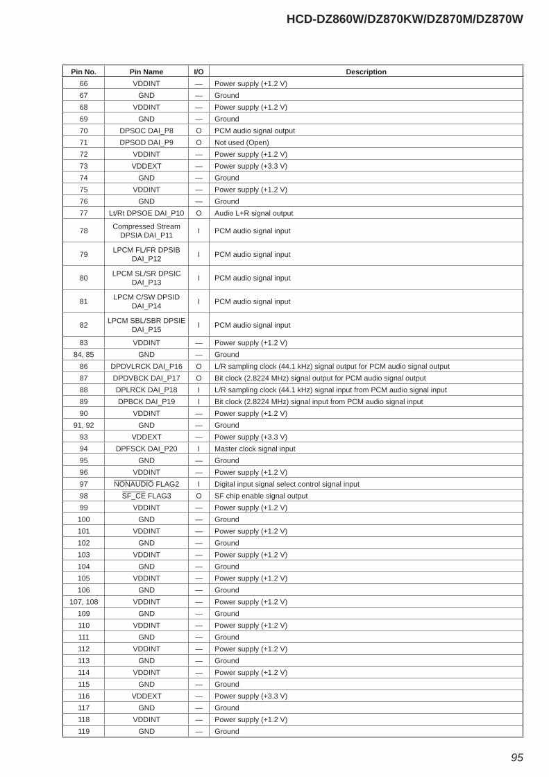
HCD-DZ860W/DZ870KW/DZ870M/DZ870W
95
Pin No. Pin Name I/O Description66 VDDINT — Power supply (+1.2 V)67 GND — Ground68 VDDINT — Power supply (+1.2 V)69 GND — Ground70 DPSOC DAI_P8 O PCM audio signal output71 DPSOD DAI_P9 O Not used (Open)72 VDDINT — Power supply (+1.2 V)73 VDDEXT — Power supply (+3.3 V)74 GND — Ground75 VDDINT — Power supply (+1.2 V)76 GND — Ground77 Lt/Rt DPSOE DAI_P10 O Audio L+R signal output
78 Compressed Stream DPSIA DAI_P11 I PCM audio signal input
79 LPCM FL/FR DPSIB DAI_P12 I PCM audio signal input
80 LPCM SL/SR DPSIC DAI_P13 I PCM audio signal input
81 LPCM C/SW DPSID DAI_P14 I PCM audio signal input
82 LPCM SBL/SBR DPSIE DAI_P15 I PCM audio signal input
83 VDDINT — Power supply (+1.2 V)84, 85 GND — Ground
86 DPDVLRCK DAI_P16 O L/R sampling clock (44.1 kHz) signal output for PCM audio signal output87 DPDVBCK DAI_P17 O Bit clock (2.8224 MHz) signal output for PCM audio signal output88 DPLRCK DAI_P18 I L/R sampling clock (44.1 kHz) signal input from PCM audio signal input89 DPBCK DAI_P19 I Bit clock (2.8224 MHz) signal input from PCM audio signal input90 VDDINT — Power supply (+1.2 V)
91, 92 GND — Ground93 VDDEXT — Power supply (+3.3 V)94 DPFSCK DAI_P20 I Master clock signal input95 GND — Ground96 VDDINT — Power supply (+1.2 V)97 NONAUDIO FLAG2 I Digital input signal select control signal input98 SF_CE FLAG3 O SF chip enable signal output99 VDDINT — Power supply (+1.2 V)100 GND — Ground101 VDDINT — Power supply (+1.2 V)102 GND — Ground103 VDDINT — Power supply (+1.2 V)104 GND — Ground105 VDDINT — Power supply (+1.2 V)106 GND — Ground
107, 108 VDDINT — Power supply (+1.2 V)109 GND — Ground110 VDDINT — Power supply (+1.2 V)111 GND — Ground112 VDDINT — Power supply (+1.2 V)113 GND — Ground114 VDDINT — Power supply (+1.2 V)115 GND — Ground116 VDDEXT — Power supply (+3.3 V)117 GND — Ground118 VDDINT — Power supply (+1.2 V)119 GND — Ground
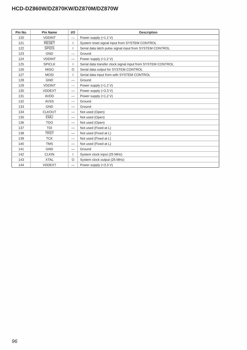
HCD-DZ860W/DZ870KW/DZ870M/DZ870W
96
Pin No. Pin Name I/O Description120 VDDINT — Power supply (+1.2 V)121 RESET I System reset signal input from SYSTEM CONTROL122 SPIDS I Serial data latch pulse signal input from SYSTEM CONTROL123 GND — Ground124 VDDINT — Power supply (+1.2 V)125 SPICLK I Serial data transfer clock signal input from SYSTEM CONTROL126 MISO O Serial data output for SYSTEM CONTROL127 MOSI I Serial data input from with SYSTEM CONTROL128 GND — Ground129 VDDINT — Power supply (+1.2 V)130 VDDEXT — Power supply (+3.3 V)131 AVDD — Power supply (+1.2 V)132 AVSS — Ground133 GND — Ground134 CLKOUT — Not used (Open)135 EMU — Not used (Open)136 TDO — Not used (Open)137 TDI — Not used (Fixed at L)138 TRST — Not used (Fixed at L)139 TCK — Not used (Fixed at L)140 TMS — Not used (Fixed at L)141 GND — Ground142 CLKIN I System clock input (25 MHz)143 XTAL O System clock output (25 MHz)144 VDDEXT — Power supply (+3.3 V)
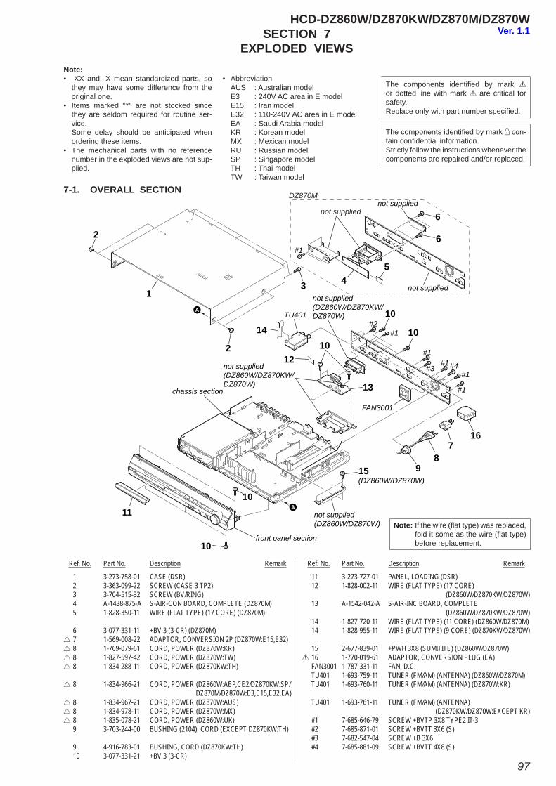
97
HCD-DZ860W/DZ870KW/DZ870M/DZ870W
1
2
2
54
14
15(DZ860W/DZ870W)
3
6
6
TU401
#1
#1
#1
#1#1
#1
#4#3
#2
FAN3001
not supplied
not supplied
not supplied(DZ860W/DZ870KW/DZ870W)
not supplied(DZ860W/DZ870KW/DZ870W)
not supplied
DZ870M
front panel section
chassis section
87
16
12
13
9
10
10
10
10
10
11 not supplied(DZ860W/DZ870W)
SECTION 7EXPLODED VIEWS
1 3-273-758-01 CASE (DSR) 2 3-363-099-22 SCREW (CASE 3 TP2) 3 3-704-515-32 SCREW (BV/RING) 4 A-1438-875-A S-AIR-CON BOARD, COMPLETE (DZ870M) 5 1-828-350-11 WIRE (FLAT TYPE) (17 CORE) (DZ870M)
6 3-077-331-11 +BV 3 (3-CR) (DZ870M)0 7 1-569-008-22 ADAPTOR, CONVERSION 2P (DZ870W:E15,E32)0 8 1-769-079-61 CORD, POWER (DZ870W:KR)0 8 1-827-597-42 CORD, POWER (DZ870W:TW)0 8 1-834-288-11 CORD, POWER (DZ870KW:TH)
0 8 1-834-966-21 CORD, POWER (DZ860W:AEP,CE2/DZ870KW:SP/ DZ870M/DZ870W:E3,E15,E32,EA)0 8 1-834-967-21 CORD, POWER (DZ870W:AUS)0 8 1-834-978-11 CORD, POWER (DZ870W:MX)0 8 1-835-078-21 CORD, POWER (DZ860W:UK) 9 3-703-244-00 BUSHING (2104), CORD (EXCEPT DZ870KW:TH)
9 4-916-783-01 BUSHING, CORD (DZ870KW:TH) 10 3-077-331-21 +BV 3 (3-CR)
11 3-273-727-01 PANEL, LOADING (DSR) 12 1-828-002-11 WIRE (FLAT TYPE) (17 CORE) (DZ860W/DZ870KW/DZ870W) 13 A-1542-042-A S-AIR-INC BOARD, COMPLETE (DZ860W/DZ870KW/DZ870W) 14 1-827-720-11 WIRE (FLAT TYPE) (11 CORE) (DZ860W/DZ870M) 14 1-828-955-11 WIRE (FLAT TYPE) (9 CORE) (DZ870KW/DZ870W)
15 2-677-839-01 +PWH 3X8 (SUMITITE) (DZ860W/DZ870W)0 16 1-770-019-61 ADAPTOR, CONVERSION PLUG (EA) FAN3001 1-787-331-11 FAN, D.C. TU401 1-693-759-11 TUNER (FM/AM) (ANTENNA) (DZ860W/DZ870M) TU401 1-693-760-11 TUNER (FM/AM) (ANTENNA) (DZ870W:KR)
TU401 1-693-761-11 TUNER (FM/AM) (ANTENNA) (DZ870KW/DZ870W:EXCEPT KR) #1 7-685-646-79 SCREW +BVTP 3X8 TYPE2 IT-3 #2 7-685-871-01 SCREW +BVTT 3X6 (S) #3 7-682-547-04 SCREW +B 3X6 #4 7-685-881-09 SCREW +BVTT 4X8 (S)
Ref. No. Part No. Description Remark Ref. No. Part No. Description Remark
Note:• -XX and -X mean standardized parts, so
they may have some difference from the original one.
• Items marked “*” are not stocked since they are seldom required for routine ser-vice.
Some delay should be anticipated when ordering these items.
• The mechanical parts with no reference number in the exploded views are not sup-plied.
• Abbreviation AUS : Australian model E3 : 240V AC area in E model E15 : Iran model E32 : 110-240V AC area in E model EA : Saudi Arabia model KR : Korean model MX : Mexican model RU : Russian model SP : Singapore model TH : Thai model TW : Taiwan model
7-1. OVERALL SECTION
Note: If the wire (fl at type) was replaced, fold it some as the wire (fl at type) before replacement.
The components identifi ed by mark 0 or dotted line with mark 0 are critical for safety. Replace only with part number specifi ed.
The components identifi ed by mark 9 con-tain confi dential information.Strictly follow the instructions whenever the components are repaired and/or replaced.
Ver. 1.1
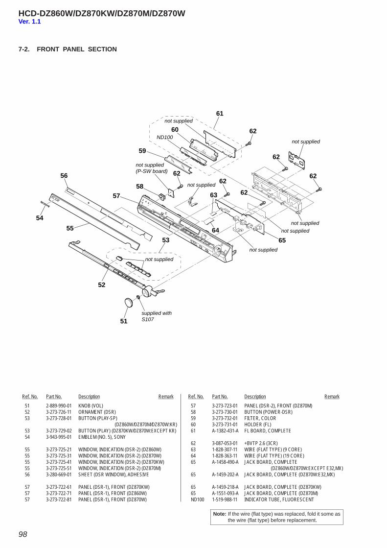
98
HCD-DZ860W/DZ870KW/DZ870M/DZ870W
51
not supplied(P-SW board)
ND100
not supplied
not supplied
not supplied
not supplied
supplied withS107
not supplied
not supplied
not supplied
52
53
5455
56
5758
59
60
61
62
6262
63
6465
62
62
62
51 2-889-990-01 KNOB (VOL) 52 3-273-726-11 ORNAMENT (DSR) 53 3-273-728-01 BUTTON (PLAY-SP)
(DZ860W/DZ870M/DZ870W:KR) 53 3-273-729-02 BUTTON (PLAY) (DZ870KW/DZ870W:EXCEPT KR) 54 3-943-995-01 EMBLEM (NO. 5), SONY
55 3-273-725-21 WINDOW, INDICATION (DSR-2) (DZ860W) 55 3-273-725-31 WINDOW, INDICATION (DSR-2) (DZ870W) 55 3-273-725-41 WINDOW, INDICATION (DSR-2) (DZ870KW) 55 3-273-725-51 WINDOW, INDICATION (DSR-2) (DZ870M) 56 3-280-669-01 SHEET (DSR WINDOW), ADHESIVE
57 3-273-722-61 PANEL (DSR-1), FRONT (DZ870KW) 57 3-273-722-71 PANEL (DSR-1), FRONT (DZ860W) 57 3-273-722-81 PANEL (DSR-1), FRONT (DZ870W)
57 3-273-723-01 PANEL (DSR-2), FRONT (DZ870M) 58 3-273-730-01 BUTTON (POWER-DSR) 59 3-273-732-01 FILTER, COLOR 60 3-273-731-01 HOLDER (FL) 61 A-1382-431-A FL BOARD, COMPLETE
62 3-087-053-01 +BVTP 2.6 (3CR) 63 1-828-307-11 WIRE (FLAT TYPE) (9 CORE) 64 1-828-363-11 WIRE (FLAT TYPE) (19 CORE) 65 A-1458-490-A JACK BOARD, COMPLETE (DZ860W/DZ870W:EXCEPT E32,MX) 65 A-1459-202-A JACK BOARD, COMPLETE (DZ870W:E32,MX)
65 A-1459-218-A JACK BOARD, COMPLETE (DZ870KW) 65 A-1551-093-A JACK BOARD, COMPLETE (DZ870M) ND100 1-519-988-11 INDICATOR TUBE, FLUORESCENT
Ref. No. Part No. Description Remark Ref. No. Part No. Description Remark
7-2. FRONT PANEL SECTION
Note: If the wire (fl at type) was replaced, fold it some as the wire (fl at type) before replacement.
Ver. 1.1
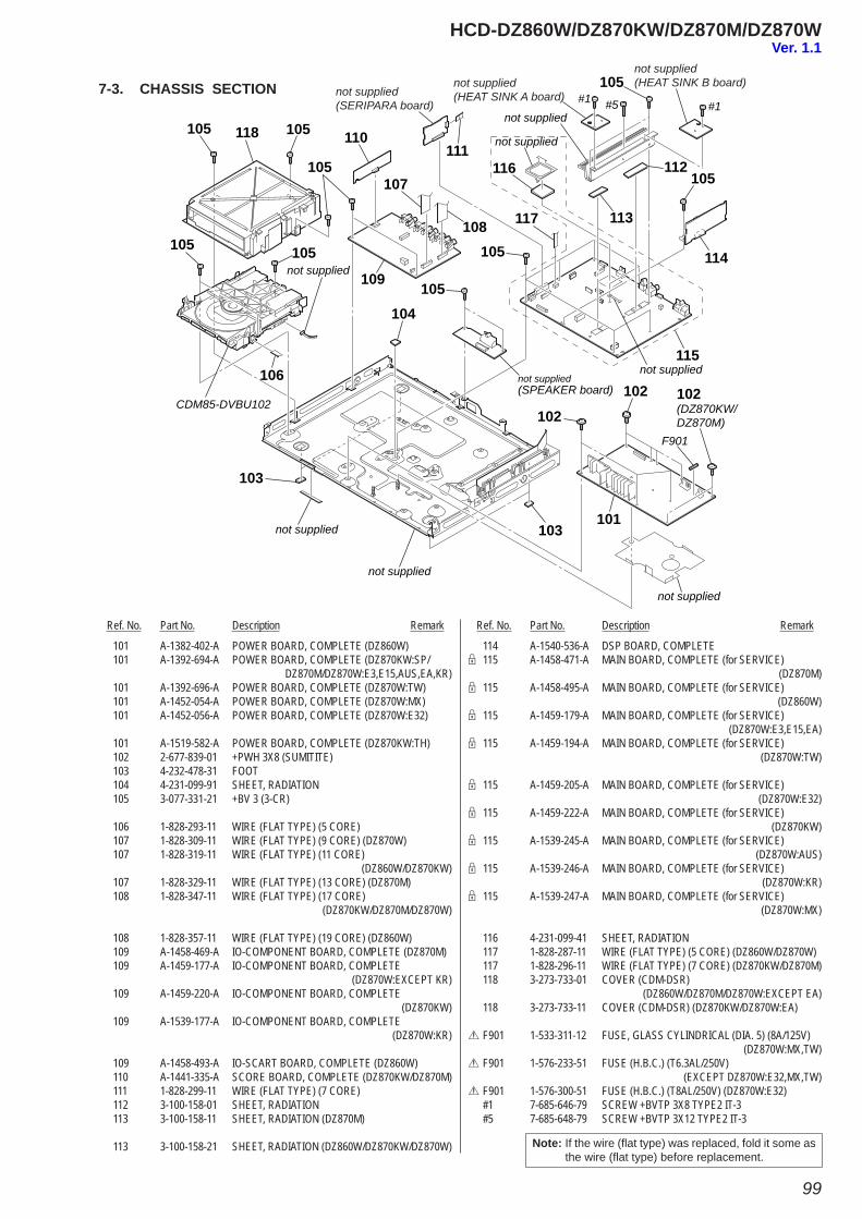
99
HCD-DZ860W/DZ870KW/DZ870M/DZ870W
101
102
103
104105
105
109
110111
107
108
112
113
116
117
114
115
105105 118
105
105
106
105 105
105
103
102
#5 #1#1
not supplied
not supplied
F901
not supplied
not supplied
not supplied
not supplied(SPEAKER board)
not supplied
not supplied
CDM85-DVBU102
not supplied(HEAT SINK B board)not supplied
(HEAT SINK A board)not supplied(SERIPARA board)
102(DZ870KW/DZ870M)
Ref. No. Part No. Description Remark Ref. No. Part No. Description Remark
101 A-1382-402-A POWER BOARD, COMPLETE (DZ860W) 101 A-1392-694-A POWER BOARD, COMPLETE (DZ870KW:SP/ DZ870M/DZ870W:E3,E15,AUS,EA,KR) 101 A-1392-696-A POWER BOARD, COMPLETE (DZ870W:TW) 101 A-1452-054-A POWER BOARD, COMPLETE (DZ870W:MX) 101 A-1452-056-A POWER BOARD, COMPLETE (DZ870W:E32)
101 A-1519-582-A POWER BOARD, COMPLETE (DZ870KW:TH) 102 2-677-839-01 +PWH 3X8 (SUMITITE) 103 4-232-478-31 FOOT 104 4-231-099-91 SHEET, RADIATION 105 3-077-331-21 +BV 3 (3-CR)
106 1-828-293-11 WIRE (FLAT TYPE) (5 CORE) 107 1-828-309-11 WIRE (FLAT TYPE) (9 CORE) (DZ870W) 107 1-828-319-11 WIRE (FLAT TYPE) (11 CORE) (DZ860W/DZ870KW) 107 1-828-329-11 WIRE (FLAT TYPE) (13 CORE) (DZ870M) 108 1-828-347-11 WIRE (FLAT TYPE) (17 CORE) (DZ870KW/DZ870M/DZ870W)
108 1-828-357-11 WIRE (FLAT TYPE) (19 CORE) (DZ860W) 109 A-1458-469-A IO-COMPONENT BOARD, COMPLETE (DZ870M) 109 A-1459-177-A IO-COMPONENT BOARD, COMPLETE (DZ870W:EXCEPT KR) 109 A-1459-220-A IO-COMPONENT BOARD, COMPLETE (DZ870KW) 109 A-1539-177-A IO-COMPONENT BOARD, COMPLETE (DZ870W:KR)
109 A-1458-493-A IO-SCART BOARD, COMPLETE (DZ860W) 110 A-1441-335-A SCORE BOARD, COMPLETE (DZ870KW/DZ870M) 111 1-828-299-11 WIRE (FLAT TYPE) (7 CORE) 112 3-100-158-01 SHEET, RADIATION 113 3-100-158-11 SHEET, RADIATION (DZ870M)
113 3-100-158-21 SHEET, RADIATION (DZ860W/DZ870KW/DZ870W)
114 A-1540-536-A DSP BOARD, COMPLETE9 115 A-1458-471-A MAIN BOARD, COMPLETE (for SERVICE) (DZ870M)9 115 A-1458-495-A MAIN BOARD, COMPLETE (for SERVICE) (DZ860W)9 115 A-1459-179-A MAIN BOARD, COMPLETE (for SERVICE) (DZ870W:E3,E15,EA)9 115 A-1459-194-A MAIN BOARD, COMPLETE (for SERVICE) (DZ870W:TW)
9 115 A-1459-205-A MAIN BOARD, COMPLETE (for SERVICE) (DZ870W:E32)9 115 A-1459-222-A MAIN BOARD, COMPLETE (for SERVICE) (DZ870KW)9 115 A-1539-245-A MAIN BOARD, COMPLETE (for SERVICE) (DZ870W:AUS)9 115 A-1539-246-A MAIN BOARD, COMPLETE (for SERVICE) (DZ870W:KR)9 115 A-1539-247-A MAIN BOARD, COMPLETE (for SERVICE) (DZ870W:MX)
116 4-231-099-41 SHEET, RADIATION 117 1-828-287-11 WIRE (FLAT TYPE) (5 CORE) (DZ860W/DZ870W) 117 1-828-296-11 WIRE (FLAT TYPE) (7 CORE) (DZ870KW/DZ870M) 118 3-273-733-01 COVER (CDM-DSR)
(DZ860W/DZ870M/DZ870W:EXCEPT EA) 118 3-273-733-11 COVER (CDM-DSR) (DZ870KW/DZ870W:EA)
0 F901 1-533-311-12 FUSE, GLASS CYLINDRICAL (DIA. 5) (8A/125V) (DZ870W:MX,TW)0 F901 1-576-233-51 FUSE (H.B.C.) (T6.3AL/250V) (EXCEPT DZ870W:E32,MX,TW)0 F901 1-576-300-51 FUSE (H.B.C.) (T8AL/250V) (DZ870W:E32) #1 7-685-646-79 SCREW +BVTP 3X8 TYPE2 IT-3 #5 7-685-648-79 SCREW +BVTP 3X12 TYPE2 IT-3
Note: If the wire (fl at type) was replaced, fold it some as the wire (fl at type) before replacement.
7-3. CHASSIS SECTION
Ver. 1.1
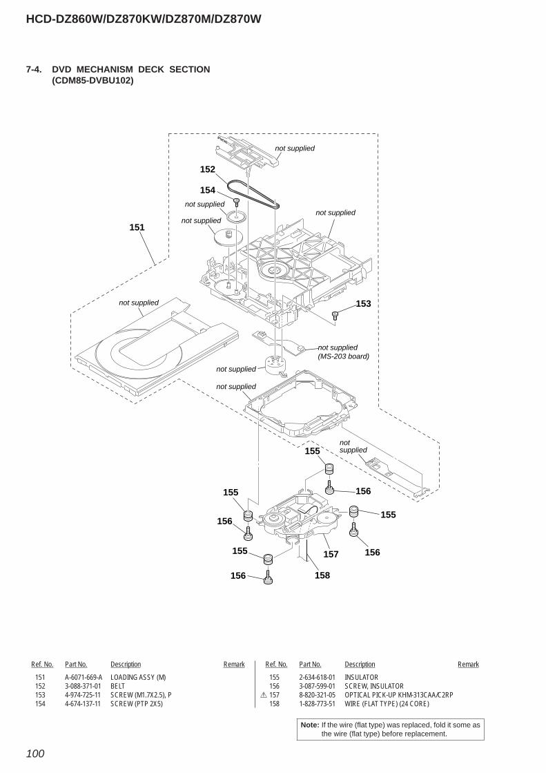
100
HCD-DZ860W/DZ870KW/DZ870M/DZ870W
7-4. DVD MECHANISM DECK SECTION (CDM85-DVBU102)
Ref. No. Part No. Description Remark Ref. No. Part No. Description Remark
151 A-6071-669-A LOADING ASSY (M) 152 3-088-371-01 BELT 153 4-974-725-11 SCREW (M1.7X2.5), P 154 4-674-137-11 SCREW (PTP 2X5)
155 2-634-618-01 INSULATOR 156 3-087-599-01 SCREW, INSULATOR0 157 8-820-321-05 OPTICAL PICK-UP KHM-313CAA/C2RP 158 1-828-773-51 WIRE (FLAT TYPE) (24 CORE)
Note: If the wire (fl at type) was replaced, fold it some as the wire (fl at type) before replacement.
not supplied
not suppliednot supplied
not supplied
not supplied
not supplied
not supplied
not supplied(MS-203 board)
notsupplied
151
154
152
153
155
155
155
155 157
158
156
156
156
156
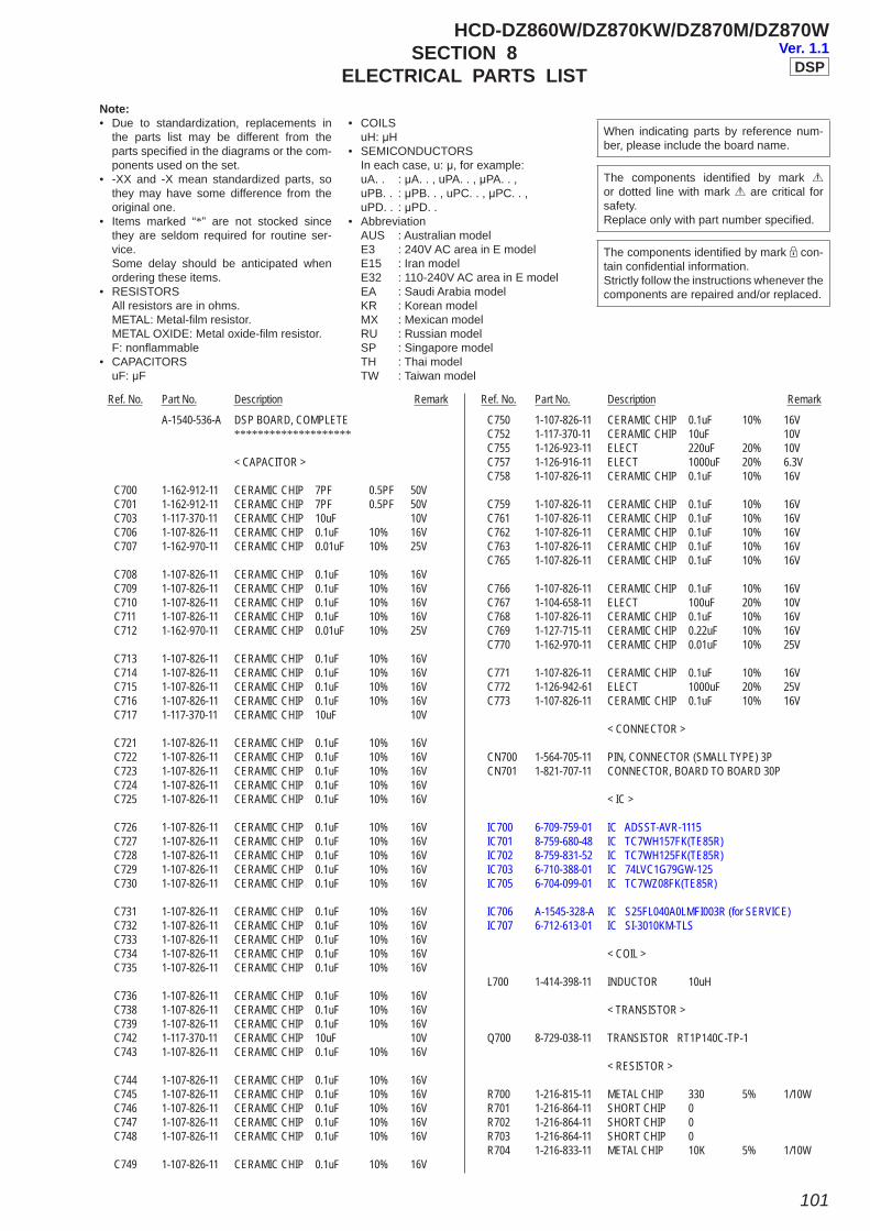
101
HCD-DZ860W/DZ870KW/DZ870M/DZ870WSECTION 8
ELECTRICAL PARTS LIST
A-1540-536-A DSP BOARD, COMPLETE ********************
< CAPACITOR >
C700 1-162-912-11 CERAMIC CHIP 7PF 0.5PF 50V C701 1-162-912-11 CERAMIC CHIP 7PF 0.5PF 50V C703 1-117-370-11 CERAMIC CHIP 10uF 10V C706 1-107-826-11 CERAMIC CHIP 0.1uF 10% 16V C707 1-162-970-11 CERAMIC CHIP 0.01uF 10% 25V
C708 1-107-826-11 CERAMIC CHIP 0.1uF 10% 16V C709 1-107-826-11 CERAMIC CHIP 0.1uF 10% 16V C710 1-107-826-11 CERAMIC CHIP 0.1uF 10% 16V C711 1-107-826-11 CERAMIC CHIP 0.1uF 10% 16V C712 1-162-970-11 CERAMIC CHIP 0.01uF 10% 25V
C713 1-107-826-11 CERAMIC CHIP 0.1uF 10% 16V C714 1-107-826-11 CERAMIC CHIP 0.1uF 10% 16V C715 1-107-826-11 CERAMIC CHIP 0.1uF 10% 16V C716 1-107-826-11 CERAMIC CHIP 0.1uF 10% 16V C717 1-117-370-11 CERAMIC CHIP 10uF 10V
C721 1-107-826-11 CERAMIC CHIP 0.1uF 10% 16V C722 1-107-826-11 CERAMIC CHIP 0.1uF 10% 16V C723 1-107-826-11 CERAMIC CHIP 0.1uF 10% 16V C724 1-107-826-11 CERAMIC CHIP 0.1uF 10% 16V C725 1-107-826-11 CERAMIC CHIP 0.1uF 10% 16V
C726 1-107-826-11 CERAMIC CHIP 0.1uF 10% 16V C727 1-107-826-11 CERAMIC CHIP 0.1uF 10% 16V C728 1-107-826-11 CERAMIC CHIP 0.1uF 10% 16V C729 1-107-826-11 CERAMIC CHIP 0.1uF 10% 16V C730 1-107-826-11 CERAMIC CHIP 0.1uF 10% 16V
C731 1-107-826-11 CERAMIC CHIP 0.1uF 10% 16V C732 1-107-826-11 CERAMIC CHIP 0.1uF 10% 16V C733 1-107-826-11 CERAMIC CHIP 0.1uF 10% 16V C734 1-107-826-11 CERAMIC CHIP 0.1uF 10% 16V C735 1-107-826-11 CERAMIC CHIP 0.1uF 10% 16V
C736 1-107-826-11 CERAMIC CHIP 0.1uF 10% 16V C738 1-107-826-11 CERAMIC CHIP 0.1uF 10% 16V C739 1-107-826-11 CERAMIC CHIP 0.1uF 10% 16V C742 1-117-370-11 CERAMIC CHIP 10uF 10V C743 1-107-826-11 CERAMIC CHIP 0.1uF 10% 16V
C744 1-107-826-11 CERAMIC CHIP 0.1uF 10% 16V C745 1-107-826-11 CERAMIC CHIP 0.1uF 10% 16V C746 1-107-826-11 CERAMIC CHIP 0.1uF 10% 16V C747 1-107-826-11 CERAMIC CHIP 0.1uF 10% 16V C748 1-107-826-11 CERAMIC CHIP 0.1uF 10% 16V
C749 1-107-826-11 CERAMIC CHIP 0.1uF 10% 16V
C750 1-107-826-11 CERAMIC CHIP 0.1uF 10% 16V C752 1-117-370-11 CERAMIC CHIP 10uF 10V C755 1-126-923-11 ELECT 220uF 20% 10V C757 1-126-916-11 ELECT 1000uF 20% 6.3V C758 1-107-826-11 CERAMIC CHIP 0.1uF 10% 16V
C759 1-107-826-11 CERAMIC CHIP 0.1uF 10% 16V C761 1-107-826-11 CERAMIC CHIP 0.1uF 10% 16V C762 1-107-826-11 CERAMIC CHIP 0.1uF 10% 16V C763 1-107-826-11 CERAMIC CHIP 0.1uF 10% 16V C765 1-107-826-11 CERAMIC CHIP 0.1uF 10% 16V
C766 1-107-826-11 CERAMIC CHIP 0.1uF 10% 16V C767 1-104-658-11 ELECT 100uF 20% 10V C768 1-107-826-11 CERAMIC CHIP 0.1uF 10% 16V C769 1-127-715-11 CERAMIC CHIP 0.22uF 10% 16V C770 1-162-970-11 CERAMIC CHIP 0.01uF 10% 25V
C771 1-107-826-11 CERAMIC CHIP 0.1uF 10% 16V C772 1-126-942-61 ELECT 1000uF 20% 25V C773 1-107-826-11 CERAMIC CHIP 0.1uF 10% 16V
< CONNECTOR >
CN700 1-564-705-11 PIN, CONNECTOR (SMALL TYPE) 3P CN701 1-821-707-11 CONNECTOR, BOARD TO BOARD 30P
< IC >
IC700 6-709-759-01 IC ADSST-AVR-1115 IC701 8-759-680-48 IC TC7WH157FK(TE85R) IC702 8-759-831-52 IC TC7WH125FK(TE85R) IC703 6-710-388-01 IC 74LVC1G79GW-125 IC705 6-704-099-01 IC TC7WZ08FK(TE85R)
IC706 A-1545-328-A IC S25FL040A0LMFI003R (for SERVICE) IC707 6-712-613-01 IC SI-3010KM-TLS
< COIL >
L700 1-414-398-11 INDUCTOR 10uH
< TRANSISTOR >
Q700 8-729-038-11 TRANSISTOR RT1P140C-TP-1
< RESISTOR >
R700 1-216-815-11 METAL CHIP 330 5% 1/10W R701 1-216-864-11 SHORT CHIP 0 R702 1-216-864-11 SHORT CHIP 0 R703 1-216-864-11 SHORT CHIP 0 R704 1-216-833-11 METAL CHIP 10K 5% 1/10W
Ref. No. Part No. Description Remark Ref. No. Part No. Description Remark
When indicating parts by reference num-ber, please include the board name.
Note:• Due to standardization, replacements in
the parts list may be different from the parts specifi ed in the diagrams or the com-ponents used on the set.
• -XX and -X mean standardized parts, so they may have some difference from the original one.
• Items marked “*” are not stocked since they are seldom required for routine ser-vice.
Some delay should be anticipated when ordering these items.
• RESISTORS All resistors are in ohms. METAL: Metal-fi lm resistor. METAL OXIDE: Metal oxide-fi lm resistor. F: nonfl ammable• CAPACITORS uF: μF
• COILS uH: μH• SEMICONDUCTORS In each case, u: μ, for example: uA. . : μA. . , uPA. . , μPA. . , uPB. . : μPB. . , uPC. . , μPC. . , uPD. . : μPD. .• Abbreviation AUS : Australian model E3 : 240V AC area in E model E15 : Iran model E32 : 110-240V AC area in E model EA : Saudi Arabia model KR : Korean model MX : Mexican model RU : Russian model SP : Singapore model TH : Thai model TW : Taiwan model
The components identifi ed by mark 0 or dotted line with mark 0 are critical for safety. Replace only with part number specifi ed.
The components identifi ed by mark 9 con-tain confi dential information.Strictly follow the instructions whenever the components are repaired and/or replaced.
DSPVer. 1.1
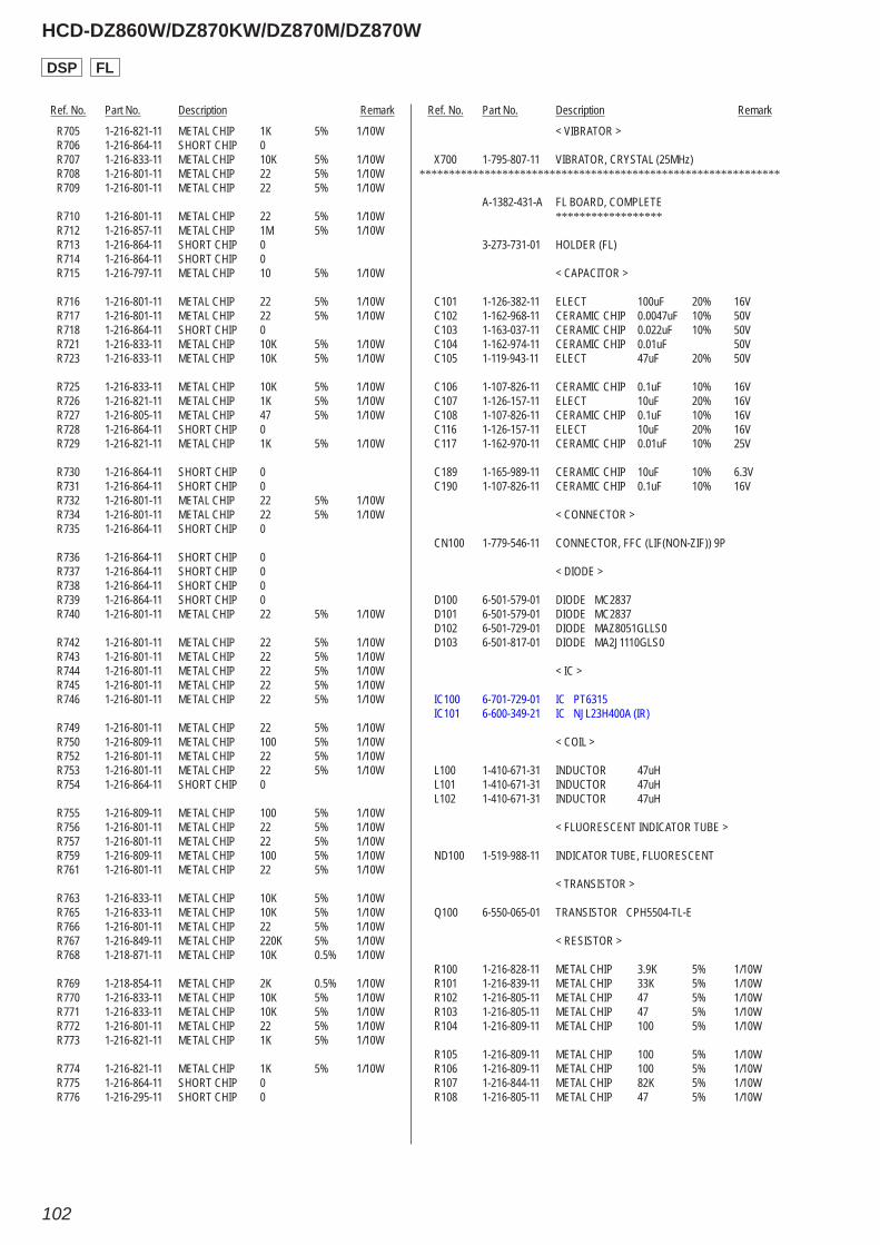
Ref. No. Part No. Description Remark Ref. No. Part No. Description Remark
HCD-DZ860W/DZ870KW/DZ870M/DZ870W
102
R705 1-216-821-11 METAL CHIP 1K 5% 1/10W R706 1-216-864-11 SHORT CHIP 0 R707 1-216-833-11 METAL CHIP 10K 5% 1/10W R708 1-216-801-11 METAL CHIP 22 5% 1/10W R709 1-216-801-11 METAL CHIP 22 5% 1/10W
R710 1-216-801-11 METAL CHIP 22 5% 1/10W R712 1-216-857-11 METAL CHIP 1M 5% 1/10W R713 1-216-864-11 SHORT CHIP 0 R714 1-216-864-11 SHORT CHIP 0 R715 1-216-797-11 METAL CHIP 10 5% 1/10W
R716 1-216-801-11 METAL CHIP 22 5% 1/10W R717 1-216-801-11 METAL CHIP 22 5% 1/10W R718 1-216-864-11 SHORT CHIP 0 R721 1-216-833-11 METAL CHIP 10K 5% 1/10W R723 1-216-833-11 METAL CHIP 10K 5% 1/10W
R725 1-216-833-11 METAL CHIP 10K 5% 1/10W R726 1-216-821-11 METAL CHIP 1K 5% 1/10W R727 1-216-805-11 METAL CHIP 47 5% 1/10W R728 1-216-864-11 SHORT CHIP 0 R729 1-216-821-11 METAL CHIP 1K 5% 1/10W
R730 1-216-864-11 SHORT CHIP 0 R731 1-216-864-11 SHORT CHIP 0 R732 1-216-801-11 METAL CHIP 22 5% 1/10W R734 1-216-801-11 METAL CHIP 22 5% 1/10W R735 1-216-864-11 SHORT CHIP 0
R736 1-216-864-11 SHORT CHIP 0 R737 1-216-864-11 SHORT CHIP 0 R738 1-216-864-11 SHORT CHIP 0 R739 1-216-864-11 SHORT CHIP 0 R740 1-216-801-11 METAL CHIP 22 5% 1/10W
R742 1-216-801-11 METAL CHIP 22 5% 1/10W R743 1-216-801-11 METAL CHIP 22 5% 1/10W R744 1-216-801-11 METAL CHIP 22 5% 1/10W R745 1-216-801-11 METAL CHIP 22 5% 1/10W R746 1-216-801-11 METAL CHIP 22 5% 1/10W
R749 1-216-801-11 METAL CHIP 22 5% 1/10W R750 1-216-809-11 METAL CHIP 100 5% 1/10W R752 1-216-801-11 METAL CHIP 22 5% 1/10W R753 1-216-801-11 METAL CHIP 22 5% 1/10W R754 1-216-864-11 SHORT CHIP 0
R755 1-216-809-11 METAL CHIP 100 5% 1/10W R756 1-216-801-11 METAL CHIP 22 5% 1/10W R757 1-216-801-11 METAL CHIP 22 5% 1/10W R759 1-216-809-11 METAL CHIP 100 5% 1/10W R761 1-216-801-11 METAL CHIP 22 5% 1/10W
R763 1-216-833-11 METAL CHIP 10K 5% 1/10W R765 1-216-833-11 METAL CHIP 10K 5% 1/10W R766 1-216-801-11 METAL CHIP 22 5% 1/10W R767 1-216-849-11 METAL CHIP 220K 5% 1/10W R768 1-218-871-11 METAL CHIP 10K 0.5% 1/10W
R769 1-218-854-11 METAL CHIP 2K 0.5% 1/10W R770 1-216-833-11 METAL CHIP 10K 5% 1/10W R771 1-216-833-11 METAL CHIP 10K 5% 1/10W R772 1-216-801-11 METAL CHIP 22 5% 1/10W R773 1-216-821-11 METAL CHIP 1K 5% 1/10W
R774 1-216-821-11 METAL CHIP 1K 5% 1/10W R775 1-216-864-11 SHORT CHIP 0 R776 1-216-295-11 SHORT CHIP 0
< VIBRATOR >
X700 1-795-807-11 VIBRATOR, CRYSTAL (25MHz)*************************************************************
A-1382-431-A FL BOARD, COMPLETE ******************
3-273-731-01 HOLDER (FL)
< CAPACITOR >
C101 1-126-382-11 ELECT 100uF 20% 16V C102 1-162-968-11 CERAMIC CHIP 0.0047uF 10% 50V C103 1-163-037-11 CERAMIC CHIP 0.022uF 10% 50V C104 1-162-974-11 CERAMIC CHIP 0.01uF 50V C105 1-119-943-11 ELECT 47uF 20% 50V
C106 1-107-826-11 CERAMIC CHIP 0.1uF 10% 16V C107 1-126-157-11 ELECT 10uF 20% 16V C108 1-107-826-11 CERAMIC CHIP 0.1uF 10% 16V C116 1-126-157-11 ELECT 10uF 20% 16V C117 1-162-970-11 CERAMIC CHIP 0.01uF 10% 25V
C189 1-165-989-11 CERAMIC CHIP 10uF 10% 6.3V C190 1-107-826-11 CERAMIC CHIP 0.1uF 10% 16V
< CONNECTOR >
CN100 1-779-546-11 CONNECTOR, FFC (LIF(NON-ZIF)) 9P
< DIODE >
D100 6-501-579-01 DIODE MC2837 D101 6-501-579-01 DIODE MC2837 D102 6-501-729-01 DIODE MAZ8051GLLS0 D103 6-501-817-01 DIODE MA2J1110GLS0
< IC >
IC100 6-701-729-01 IC PT6315 IC101 6-600-349-21 IC NJL23H400A (IR)
< COIL >
L100 1-410-671-31 INDUCTOR 47uH L101 1-410-671-31 INDUCTOR 47uH L102 1-410-671-31 INDUCTOR 47uH
< FLUORESCENT INDICATOR TUBE >
ND100 1-519-988-11 INDICATOR TUBE, FLUORESCENT
< TRANSISTOR >
Q100 6-550-065-01 TRANSISTOR CPH5504-TL-E
< RESISTOR >
R100 1-216-828-11 METAL CHIP 3.9K 5% 1/10W R101 1-216-839-11 METAL CHIP 33K 5% 1/10W R102 1-216-805-11 METAL CHIP 47 5% 1/10W R103 1-216-805-11 METAL CHIP 47 5% 1/10W R104 1-216-809-11 METAL CHIP 100 5% 1/10W
R105 1-216-809-11 METAL CHIP 100 5% 1/10W R106 1-216-809-11 METAL CHIP 100 5% 1/10W R107 1-216-844-11 METAL CHIP 82K 5% 1/10W R108 1-216-805-11 METAL CHIP 47 5% 1/10W
DSP FL
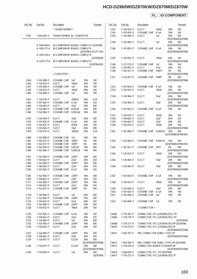
Ref. No. Part No. Description Remark Ref. No. Part No. Description Remark
HCD-DZ860W/DZ870KW/DZ870M/DZ870W
103103
< TRANSFORMER >
T100 1-443-645-11 TRANSFORMER, DC CONVERTER*************************************************************
A-1458-469-A IO-COMPONENT BOARD, COMPLETE (DZ870M) A-1459-177-A IO-COMPONENT BOARD, COMPLETE (DZ870W:EXCEPT KR) A-1459-220-A IO-COMPONENT BOARD, COMPLETE (DZ870KW) A-1539-177-A IO-COMPONENT BOARD, COMPLETE (DZ870W:KR) *****************************
< CAPACITOR >
C454 1-165-908-11 CERAMIC CHIP 1uF 10% 10V C456 1-126-933-11 ELECT 100uF 20% 16V C457 1-165-908-11 CERAMIC CHIP 1uF 10% 10V C458 1-126-933-11 ELECT 100uF 20% 16V C460 1-165-908-11 CERAMIC CHIP 1uF 10% 10V
C462 1-126-916-11 ELECT 1000uF 20% 6.3V C463 1-107-826-11 CERAMIC CHIP 0.1uF 10% 16V C466 1-126-965-11 ELECT 22uF 20% 50V C467 1-162-964-11 CERAMIC CHIP 0.001uF 10% 50V C468 1-162-966-11 CERAMIC CHIP 0.0022uF 10% 50V
C470 1-126-964-11 ELECT 10uF 20% 50V C473 1-107-826-11 CERAMIC CHIP 0.1uF 10% 16V C474 1-126-925-11 ELECT 470uF 20% 10V C476 1-126-964-11 ELECT 10uF 20% 50V C478 1-126-916-11 ELECT 1000uF 20% 6.3V
C480 1-165-908-11 CERAMIC CHIP 1uF 10% 10V C481 1-162-927-11 CERAMIC CHIP 100PF 5% 50V C482 1-162-927-11 CERAMIC CHIP 100PF 5% 50V C488 1-162-964-11 CERAMIC CHIP 0.001uF 10% 50V C489 1-162-966-11 CERAMIC CHIP 0.0022uF 10% 50V
C491 1-162-960-11 CERAMIC CHIP 220PF 10% 50V C495 1-104-662-11 ELECT 22uF 20% 25V C496 1-162-960-11 CERAMIC CHIP 220PF 10% 50V C499 1-104-662-11 ELECT 22uF 20% 25V C504 1-107-826-11 CERAMIC CHIP 0.1uF 10% 16V
C505 1-162-960-11 CERAMIC CHIP 220PF 10% 50V C509 1-104-662-11 ELECT 22uF 20% 25V C511 1-162-960-11 CERAMIC CHIP 220PF 10% 50V C512 1-104-662-11 ELECT 22uF 20% 25V C514 1-162-927-11 CERAMIC CHIP 100PF 5% 50V
C518 1-126-960-11 ELECT 1uF 20% 50V C521 1-162-960-11 CERAMIC CHIP 220PF 10% 50V C524 1-104-662-11 ELECT 22uF 20% 25V C525 1-162-960-11 CERAMIC CHIP 220PF 10% 50V C528 1-126-933-11 ELECT 100uF 20% 16V
C529 1-107-826-11 CERAMIC CHIP 0.1uF 10% 16V C530 1-104-662-11 ELECT 22uF 20% 25V C533 1-126-960-11 ELECT 1uF 20% 50V C535 1-162-960-11 CERAMIC CHIP 220PF 10% 50V C536 1-104-662-11 ELECT 22uF 20% 25V
C537 1-162-960-11 CERAMIC CHIP 220PF 10% 50V C538 1-104-662-11 ELECT 22uF 20% 25V C539 1-126-957-11 ELECT 0.22uF 20% 50V (DZ870KW/DZ870M) C540 1-126-957-11 ELECT 0.22uF 20% 50V (DZ870KW/DZ870M) C540 1-126-960-11 ELECT 1uF 20% 50V (DZ870W)
C541 1-126-933-11 ELECT 100uF 20% 16V C542 1-107-826-11 CERAMIC CHIP 0.1uF 10% 16V C543 1-126-960-11 ELECT 1uF 20% 50V (DZ870KW/DZ870M) C544 1-126-960-11 ELECT 1uF 20% 50V (DZ870KW/DZ870M) C546 1-107-826-11 CERAMIC CHIP 0.1uF 10% 16V (DZ870KW/DZ870M)
C547 1-126-933-11 ELECT 100uF 20% 16V (DZ870KW/DZ870M) C548 1-127-573-11 CERAMIC CHIP 1uF 10% 16V C549 1-126-947-11 ELECT 47uF 20% 35V C550 1-162-927-11 CERAMIC CHIP 100PF 5% 50V (DZ870KW/DZ870M) C551 1-162-927-11 CERAMIC CHIP 100PF 5% 50V (DZ870KW/DZ870M)
C552 1-107-826-11 CERAMIC CHIP 0.1uF 10% 16V C553 1-126-933-11 ELECT 100uF 20% 16V (DZ870KW/DZ870M) C554 1-126-966-11 ELECT 33uF 20% 50V (DZ870KW/DZ870M) C555 1-126-964-11 ELECT 10uF 20% 50V (DZ870KW/DZ870M) C556 1-107-826-11 CERAMIC CHIP 0.1uF 10% 16V
C557 1-126-933-11 ELECT 100uF 20% 16V C558 1-104-662-11 ELECT 22uF 20% 25V C559 1-104-662-11 ELECT 22uF 20% 25V C560 1-126-933-11 ELECT 100uF 20% 16V (DZ870KW/DZ870M) C561 1-162-968-11 CERAMIC CHIP 0.0047uF 10% 50V (DZ870M/DZ870W:KR)
C562 1-162-968-11 CERAMIC CHIP 0.0047uF 10% 50V (DZ870M/DZ870W:KR) C563 1-162-921-11 CERAMIC CHIP 33PF 5% 50V (DZ870KW/DZ870M) C564 1-126-933-11 ELECT 100uF 20% 16V (DZ870KW/DZ870M) C565 1-126-964-11 ELECT 10uF 20% 50V (DZ870KW/DZ870M) C566 1-126-964-11 ELECT 10uF 20% 50V (DZ870KW/DZ870M)
C567 1-107-826-11 CERAMIC CHIP 0.1uF 10% 16V (DZ870KW/DZ870M) C568 1-126-933-11 ELECT 100uF 20% 16V (DZ870KW/DZ870M) C569 1-126-964-11 ELECT 10uF 20% 50V C620 1-107-826-11 CERAMIC CHIP 0.1uF 10% 16V C621 1-165-908-11 CERAMIC CHIP 1uF 10% 10V
C622 1-165-908-11 CERAMIC CHIP 1uF 10% 10V
< CONNECTOR >
CN402 1-779-285-11 CONNECTOR, FFC (LIF(NON-ZIF)) 17P CN406 1-779-279-11 CONNECTOR, FFC (LIF(NON-ZIF)) 11P (DZ870KW) CN408 1-779-277-11 CONNECTOR, FFC (LIF(NON-ZIF)) 9P (DZ870W) CN410 1-779-275-11 CONNECTOR, FFC (LIF(NON-ZIF)) 7P (DZ870KW/DZ870M) CN411 1-564-707-11 PIN, CONNECTOR (SMALL TYPE) 5P (DZ870KW/DZ870M)
CN412 1-564-706-11 PIN, CONNECTOR (SMALL TYPE) 4P (DZ870W) CN413 1-778-226-21 CONNECTOR, BOARD TO BOARD 6P (DZ870KW/DZ870M) CN414 1-568-830-11 CONNECTOR, FFC 11P (DZ870M) CN415 1-779-275-11 CONNECTOR, FFC (LIF(NON-ZIF)) 7P
IO-COMPONENTFL
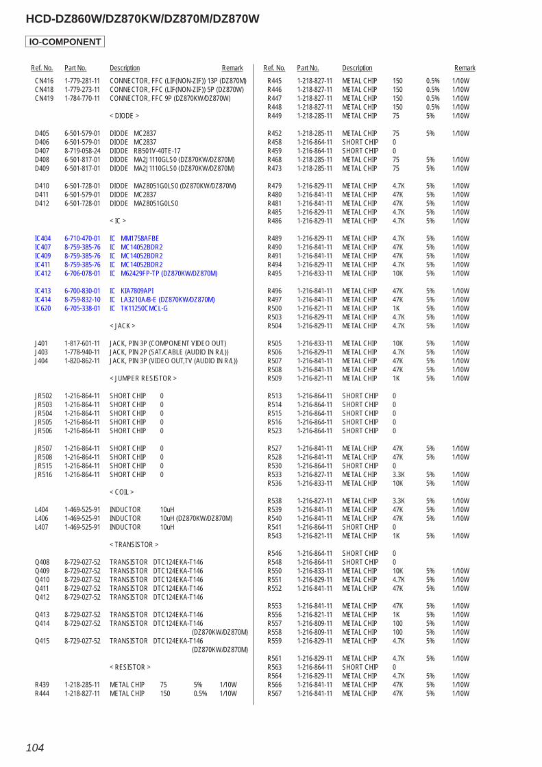
Ref. No. Part No. Description Remark Ref. No. Part No. Description Remark
HCD-DZ860W/DZ870KW/DZ870M/DZ870W
104
CN416 1-779-281-11 CONNECTOR, FFC (LIF(NON-ZIF)) 13P (DZ870M) CN418 1-779-273-11 CONNECTOR, FFC (LIF(NON-ZIF)) 5P (DZ870W) CN419 1-784-770-11 CONNECTOR, FFC 9P (DZ870KW/DZ870W)
< DIODE >
D405 6-501-579-01 DIODE MC2837 D406 6-501-579-01 DIODE MC2837 D407 8-719-058-24 DIODE RB501V-40TE-17 D408 6-501-817-01 DIODE MA2J1110GLS0 (DZ870KW/DZ870M) D409 6-501-817-01 DIODE MA2J1110GLS0 (DZ870KW/DZ870M)
D410 6-501-728-01 DIODE MAZ8051G0LS0 (DZ870KW/DZ870M) D411 6-501-579-01 DIODE MC2837 D412 6-501-728-01 DIODE MAZ8051G0LS0
< IC >
IC404 6-710-470-01 IC MM1758AFBE IC407 8-759-385-76 IC MC14052BDR2 IC409 8-759-385-76 IC MC14052BDR2 IC411 8-759-385-76 IC MC14052BDR2 IC412 6-706-078-01 IC M62429FP-TP (DZ870KW/DZ870M)
IC413 6-700-830-01 IC KIA7809API IC414 8-759-832-10 IC LA3210A/B-E (DZ870KW/DZ870M) IC620 6-705-338-01 IC TK11250CMCL-G
< JACK >
J401 1-817-601-11 JACK, PIN 3P (COMPONENT VIDEO OUT) J403 1-778-940-11 JACK, PIN 2P (SAT/CABLE (AUDIO IN R/L)) J404 1-820-862-11 JACK, PIN 3P (VIDEO OUT,TV (AUDIO IN R/L))
< JUMPER RESISTOR >
JR502 1-216-864-11 SHORT CHIP 0 JR503 1-216-864-11 SHORT CHIP 0 JR504 1-216-864-11 SHORT CHIP 0 JR505 1-216-864-11 SHORT CHIP 0 JR506 1-216-864-11 SHORT CHIP 0
JR507 1-216-864-11 SHORT CHIP 0 JR508 1-216-864-11 SHORT CHIP 0 JR515 1-216-864-11 SHORT CHIP 0 JR516 1-216-864-11 SHORT CHIP 0
< COIL >
L404 1-469-525-91 INDUCTOR 10uH L406 1-469-525-91 INDUCTOR 10uH (DZ870KW/DZ870M) L407 1-469-525-91 INDUCTOR 10uH
< TRANSISTOR >
Q408 8-729-027-52 TRANSISTOR DTC124EKA-T146 Q409 8-729-027-52 TRANSISTOR DTC124EKA-T146 Q410 8-729-027-52 TRANSISTOR DTC124EKA-T146 Q411 8-729-027-52 TRANSISTOR DTC124EKA-T146 Q412 8-729-027-52 TRANSISTOR DTC124EKA-T146
Q413 8-729-027-52 TRANSISTOR DTC124EKA-T146 Q414 8-729-027-52 TRANSISTOR DTC124EKA-T146 (DZ870KW/DZ870M) Q415 8-729-027-52 TRANSISTOR DTC124EKA-T146 (DZ870KW/DZ870M)
< RESISTOR >
R439 1-218-285-11 METAL CHIP 75 5% 1/10W R444 1-218-827-11 METAL CHIP 150 0.5% 1/10W
R445 1-218-827-11 METAL CHIP 150 0.5% 1/10W R446 1-218-827-11 METAL CHIP 150 0.5% 1/10W R447 1-218-827-11 METAL CHIP 150 0.5% 1/10W R448 1-218-827-11 METAL CHIP 150 0.5% 1/10W R449 1-218-285-11 METAL CHIP 75 5% 1/10W
R452 1-218-285-11 METAL CHIP 75 5% 1/10W R458 1-216-864-11 SHORT CHIP 0 R459 1-216-864-11 SHORT CHIP 0 R468 1-218-285-11 METAL CHIP 75 5% 1/10W R473 1-218-285-11 METAL CHIP 75 5% 1/10W
R479 1-216-829-11 METAL CHIP 4.7K 5% 1/10W R480 1-216-841-11 METAL CHIP 47K 5% 1/10W R481 1-216-841-11 METAL CHIP 47K 5% 1/10W R485 1-216-829-11 METAL CHIP 4.7K 5% 1/10W R486 1-216-829-11 METAL CHIP 4.7K 5% 1/10W
R489 1-216-829-11 METAL CHIP 4.7K 5% 1/10W R490 1-216-841-11 METAL CHIP 47K 5% 1/10W R491 1-216-841-11 METAL CHIP 47K 5% 1/10W R494 1-216-829-11 METAL CHIP 4.7K 5% 1/10W R495 1-216-833-11 METAL CHIP 10K 5% 1/10W
R496 1-216-841-11 METAL CHIP 47K 5% 1/10W R497 1-216-841-11 METAL CHIP 47K 5% 1/10W R500 1-216-821-11 METAL CHIP 1K 5% 1/10W R503 1-216-829-11 METAL CHIP 4.7K 5% 1/10W R504 1-216-829-11 METAL CHIP 4.7K 5% 1/10W
R505 1-216-833-11 METAL CHIP 10K 5% 1/10W R506 1-216-829-11 METAL CHIP 4.7K 5% 1/10W R507 1-216-841-11 METAL CHIP 47K 5% 1/10W R508 1-216-841-11 METAL CHIP 47K 5% 1/10W R509 1-216-821-11 METAL CHIP 1K 5% 1/10W
R513 1-216-864-11 SHORT CHIP 0 R514 1-216-864-11 SHORT CHIP 0 R515 1-216-864-11 SHORT CHIP 0 R516 1-216-864-11 SHORT CHIP 0 R523 1-216-864-11 SHORT CHIP 0
R527 1-216-841-11 METAL CHIP 47K 5% 1/10W R528 1-216-841-11 METAL CHIP 47K 5% 1/10W R530 1-216-864-11 SHORT CHIP 0 R533 1-216-827-11 METAL CHIP 3.3K 5% 1/10W R536 1-216-833-11 METAL CHIP 10K 5% 1/10W
R538 1-216-827-11 METAL CHIP 3.3K 5% 1/10W R539 1-216-841-11 METAL CHIP 47K 5% 1/10W R540 1-216-841-11 METAL CHIP 47K 5% 1/10W R541 1-216-864-11 SHORT CHIP 0 R543 1-216-821-11 METAL CHIP 1K 5% 1/10W
R546 1-216-864-11 SHORT CHIP 0 R548 1-216-864-11 SHORT CHIP 0 R550 1-216-833-11 METAL CHIP 10K 5% 1/10W R551 1-216-829-11 METAL CHIP 4.7K 5% 1/10W R552 1-216-841-11 METAL CHIP 47K 5% 1/10W
R553 1-216-841-11 METAL CHIP 47K 5% 1/10W R556 1-216-821-11 METAL CHIP 1K 5% 1/10W R557 1-216-809-11 METAL CHIP 100 5% 1/10W R558 1-216-809-11 METAL CHIP 100 5% 1/10W R559 1-216-829-11 METAL CHIP 4.7K 5% 1/10W
R561 1-216-829-11 METAL CHIP 4.7K 5% 1/10W R563 1-216-864-11 SHORT CHIP 0 R564 1-216-829-11 METAL CHIP 4.7K 5% 1/10W R566 1-216-841-11 METAL CHIP 47K 5% 1/10W R567 1-216-841-11 METAL CHIP 47K 5% 1/10W
IO-COMPONENT
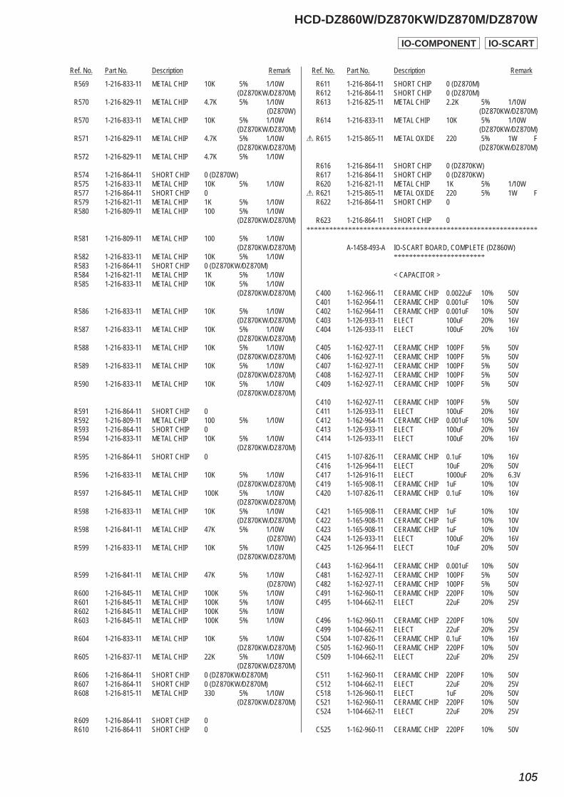
Ref. No. Part No. Description Remark Ref. No. Part No. Description Remark
HCD-DZ860W/DZ870KW/DZ870M/DZ870W
105105
R569 1-216-833-11 METAL CHIP 10K 5% 1/10W (DZ870KW/DZ870M) R570 1-216-829-11 METAL CHIP 4.7K 5% 1/10W (DZ870W) R570 1-216-833-11 METAL CHIP 10K 5% 1/10W (DZ870KW/DZ870M) R571 1-216-829-11 METAL CHIP 4.7K 5% 1/10W (DZ870KW/DZ870M) R572 1-216-829-11 METAL CHIP 4.7K 5% 1/10W
R574 1-216-864-11 SHORT CHIP 0 (DZ870W) R575 1-216-833-11 METAL CHIP 10K 5% 1/10W R577 1-216-864-11 SHORT CHIP 0 R579 1-216-821-11 METAL CHIP 1K 5% 1/10W R580 1-216-809-11 METAL CHIP 100 5% 1/10W (DZ870KW/DZ870M)
R581 1-216-809-11 METAL CHIP 100 5% 1/10W (DZ870KW/DZ870M) R582 1-216-833-11 METAL CHIP 10K 5% 1/10W R583 1-216-864-11 SHORT CHIP 0 (DZ870KW/DZ870M) R584 1-216-821-11 METAL CHIP 1K 5% 1/10W R585 1-216-833-11 METAL CHIP 10K 5% 1/10W (DZ870KW/DZ870M)
R586 1-216-833-11 METAL CHIP 10K 5% 1/10W (DZ870KW/DZ870M) R587 1-216-833-11 METAL CHIP 10K 5% 1/10W (DZ870KW/DZ870M) R588 1-216-833-11 METAL CHIP 10K 5% 1/10W (DZ870KW/DZ870M) R589 1-216-833-11 METAL CHIP 10K 5% 1/10W (DZ870KW/DZ870M) R590 1-216-833-11 METAL CHIP 10K 5% 1/10W (DZ870KW/DZ870M)
R591 1-216-864-11 SHORT CHIP 0 R592 1-216-809-11 METAL CHIP 100 5% 1/10W R593 1-216-864-11 SHORT CHIP 0 R594 1-216-833-11 METAL CHIP 10K 5% 1/10W (DZ870KW/DZ870M) R595 1-216-864-11 SHORT CHIP 0
R596 1-216-833-11 METAL CHIP 10K 5% 1/10W (DZ870KW/DZ870M) R597 1-216-845-11 METAL CHIP 100K 5% 1/10W (DZ870KW/DZ870M) R598 1-216-833-11 METAL CHIP 10K 5% 1/10W (DZ870KW/DZ870M) R598 1-216-841-11 METAL CHIP 47K 5% 1/10W (DZ870W) R599 1-216-833-11 METAL CHIP 10K 5% 1/10W (DZ870KW/DZ870M)
R599 1-216-841-11 METAL CHIP 47K 5% 1/10W (DZ870W) R600 1-216-845-11 METAL CHIP 100K 5% 1/10W R601 1-216-845-11 METAL CHIP 100K 5% 1/10W R602 1-216-845-11 METAL CHIP 100K 5% 1/10W R603 1-216-845-11 METAL CHIP 100K 5% 1/10W
R604 1-216-833-11 METAL CHIP 10K 5% 1/10W (DZ870KW/DZ870M) R605 1-216-837-11 METAL CHIP 22K 5% 1/10W (DZ870KW/DZ870M) R606 1-216-864-11 SHORT CHIP 0 (DZ870KW/DZ870M) R607 1-216-864-11 SHORT CHIP 0 (DZ870KW/DZ870M) R608 1-216-815-11 METAL CHIP 330 5% 1/10W (DZ870KW/DZ870M)
R609 1-216-864-11 SHORT CHIP 0 R610 1-216-864-11 SHORT CHIP 0
R611 1-216-864-11 SHORT CHIP 0 (DZ870M) R612 1-216-864-11 SHORT CHIP 0 (DZ870M) R613 1-216-825-11 METAL CHIP 2.2K 5% 1/10W (DZ870KW/DZ870M) R614 1-216-833-11 METAL CHIP 10K 5% 1/10W (DZ870KW/DZ870M)0 R615 1-215-865-11 METAL OXIDE 220 5% 1W F (DZ870KW/DZ870M)
R616 1-216-864-11 SHORT CHIP 0 (DZ870KW) R617 1-216-864-11 SHORT CHIP 0 (DZ870KW) R620 1-216-821-11 METAL CHIP 1K 5% 1/10W0 R621 1-215-865-11 METAL OXIDE 220 5% 1W F R622 1-216-864-11 SHORT CHIP 0
R623 1-216-864-11 SHORT CHIP 0*************************************************************
A-1458-493-A IO-SCART BOARD, COMPLETE (DZ860W) ************************
< CAPACITOR >
C400 1-162-966-11 CERAMIC CHIP 0.0022uF 10% 50V C401 1-162-964-11 CERAMIC CHIP 0.001uF 10% 50V C402 1-162-964-11 CERAMIC CHIP 0.001uF 10% 50V C403 1-126-933-11 ELECT 100uF 20% 16V C404 1-126-933-11 ELECT 100uF 20% 16V
C405 1-162-927-11 CERAMIC CHIP 100PF 5% 50V C406 1-162-927-11 CERAMIC CHIP 100PF 5% 50V C407 1-162-927-11 CERAMIC CHIP 100PF 5% 50V C408 1-162-927-11 CERAMIC CHIP 100PF 5% 50V C409 1-162-927-11 CERAMIC CHIP 100PF 5% 50V
C410 1-162-927-11 CERAMIC CHIP 100PF 5% 50V C411 1-126-933-11 ELECT 100uF 20% 16V C412 1-162-964-11 CERAMIC CHIP 0.001uF 10% 50V C413 1-126-933-11 ELECT 100uF 20% 16V C414 1-126-933-11 ELECT 100uF 20% 16V
C415 1-107-826-11 CERAMIC CHIP 0.1uF 10% 16V C416 1-126-964-11 ELECT 10uF 20% 50V C417 1-126-916-11 ELECT 1000uF 20% 6.3V C419 1-165-908-11 CERAMIC CHIP 1uF 10% 10V C420 1-107-826-11 CERAMIC CHIP 0.1uF 10% 16V
C421 1-165-908-11 CERAMIC CHIP 1uF 10% 10V C422 1-165-908-11 CERAMIC CHIP 1uF 10% 10V C423 1-165-908-11 CERAMIC CHIP 1uF 10% 10V C424 1-126-933-11 ELECT 100uF 20% 16V C425 1-126-964-11 ELECT 10uF 20% 50V
C443 1-162-964-11 CERAMIC CHIP 0.001uF 10% 50V C481 1-162-927-11 CERAMIC CHIP 100PF 5% 50V C482 1-162-927-11 CERAMIC CHIP 100PF 5% 50V C491 1-162-960-11 CERAMIC CHIP 220PF 10% 50V C495 1-104-662-11 ELECT 22uF 20% 25V
C496 1-162-960-11 CERAMIC CHIP 220PF 10% 50V C499 1-104-662-11 ELECT 22uF 20% 25V C504 1-107-826-11 CERAMIC CHIP 0.1uF 10% 16V C505 1-162-960-11 CERAMIC CHIP 220PF 10% 50V C509 1-104-662-11 ELECT 22uF 20% 25V
C511 1-162-960-11 CERAMIC CHIP 220PF 10% 50V C512 1-104-662-11 ELECT 22uF 20% 25V C518 1-126-960-11 ELECT 1uF 20% 50V C521 1-162-960-11 CERAMIC CHIP 220PF 10% 50V C524 1-104-662-11 ELECT 22uF 20% 25V
C525 1-162-960-11 CERAMIC CHIP 220PF 10% 50V
IO-COMPONENT IO-SCART
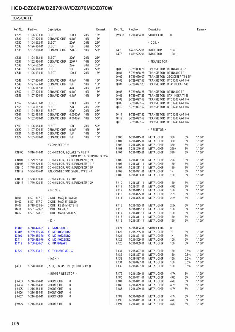
Ref. No. Part No. Description Remark Ref. No. Part No. Description Remark
HCD-DZ860W/DZ870KW/DZ870M/DZ870W
106
C528 1-126-933-11 ELECT 100uF 20% 16V C529 1-107-826-11 CERAMIC CHIP 0.1uF 10% 16V C530 1-104-662-11 ELECT 22uF 20% 25V C533 1-126-960-11 ELECT 1uF 20% 50V C535 1-162-960-11 CERAMIC CHIP 220PF 10% 50V
C536 1-104-662-11 ELECT 22uF 20% 25V C537 1-162-960-11 CERAMIC CHIP 220PF 10% 50V C538 1-104-662-11 ELECT 22uF 20% 25V C540 1-126-960-11 ELECT 1uF 20% 50V C541 1-126-933-11 ELECT 100uF 20% 16V
C542 1-107-826-11 CERAMIC CHIP 0.1uF 10% 16V C548 1-127-573-11 CERAMIC CHIP 1uF 10% 16V C549 1-126-947-11 ELECT 47uF 20% 35V C552 1-107-826-11 CERAMIC CHIP 0.1uF 10% 16V C556 1-107-826-11 CERAMIC CHIP 0.1uF 10% 16V
C557 1-126-933-11 ELECT 100uF 20% 16V C558 1-104-662-11 ELECT 22uF 20% 25V C559 1-104-662-11 ELECT 22uF 20% 25V C561 1-162-968-11 CERAMIC CHIP 0.0047uF 10% 50V C562 1-162-968-11 CERAMIC CHIP 0.0047uF 10% 50V
C569 1-126-964-11 ELECT 10uF 20% 50V C620 1-107-826-11 CERAMIC CHIP 0.1uF 10% 16V C621 1-165-908-11 CERAMIC CHIP 1uF 10% 10V C622 1-165-908-11 CERAMIC CHIP 1uF 10% 10V
< CONNECTOR >
CN400 1-816-044-11 CONNECTOR, SQUARE TYPE 21P (EURO AV T OUTPUT(TO TV)) CN401 1-779-287-11 CONNECTOR, FFC (LIF(NON-ZIF)) 19P CN405 1-779-279-11 CONNECTOR, FFC (LIF(NON-ZIF)) 11P CN410 1-779-273-11 CONNECTOR, FFC (LIF(NON-ZIF)) 5P CN412 1-564-706-11 PIN, CONNECTOR (SMALL TYPE) 4P
CN414 1-568-830-11 CONNECTOR, FFC 11P CN415 1-779-275-11 CONNECTOR, FFC (LIF(NON-ZIF)) 7P
< DIODE >
D401 6-501-817-01 DIODE MA2J1110GLS0 D402 6-501-817-01 DIODE MA2J1110GLS0 D407 8-719-058-24 DIODE RB501V-40TE-17 D411 6-501-579-01 DIODE MC2837 D412 6-501-728-01 DIODE MAZ8051G0LS0
< IC >
IC400 6-710-470-01 IC MM1758AFBE IC407 8-759-385-76 IC MC14052BDR2 IC409 8-759-385-76 IC MC14052BDR2 IC411 8-759-385-76 IC MC14052BDR2 IC413 6-700-830-01 IC KIA7809API
IC620 6-705-338-01 IC TK11250CMCL-G
< JACK >
J403 1-778-940-11 JACK, PIN 2P (LINE (AUDIO IN R/L))
< JUMPER RESISTOR >
JR403 1-216-864-11 SHORT CHIP 0 JR404 1-216-864-11 SHORT CHIP 0 JR405 1-216-864-11 SHORT CHIP 0 JR406 1-216-864-11 SHORT CHIP 0 JR407 1-216-864-11 SHORT CHIP 0
JW427 1-216-864-11 SHORT CHIP 0
JW433 1-216-864-11 SHORT CHIP 0
< COIL >
L401 1-469-525-91 INDUCTOR 10uH L407 1-469-525-91 INDUCTOR 10uH
< TRANSISTOR >
Q400 8-729-038-28 TRANSISTOR RT1N441C-TP-1 Q401 8-729-038-28 TRANSISTOR RT1N441C-TP-1 Q402 8-729-620-07 TRANSISTOR 2SC3052EF-T1-LEF Q403 8-729-027-52 TRANSISTOR DTC124EKA-T146 Q404 8-729-027-23 TRANSISTOR DTA114EKA-T146
Q405 8-729-038-28 TRANSISTOR RT1N441C-TP-1 Q406 8-729-027-23 TRANSISTOR DTA114EKA-T146 Q408 8-729-027-52 TRANSISTOR DTC124EKA-T146 Q409 8-729-027-52 TRANSISTOR DTC124EKA-T146 Q410 8-729-027-52 TRANSISTOR DTC124EKA-T146
Q411 8-729-027-52 TRANSISTOR DTC124EKA-T146 Q412 8-729-027-52 TRANSISTOR DTC124EKA-T146 Q413 8-729-027-52 TRANSISTOR DTC124EKA-T146
< RESISTOR >
R400 1-216-815-11 METAL CHIP 330 5% 1/10W R401 1-216-815-11 METAL CHIP 330 5% 1/10W R402 1-216-815-11 METAL CHIP 330 5% 1/10W R403 1-216-849-11 METAL CHIP 220K 5% 1/10W R404 1-216-815-11 METAL CHIP 330 5% 1/10W
R405 1-216-837-11 METAL CHIP 22K 5% 1/10W R406 1-216-811-11 METAL CHIP 150 5% 1/10W R407 1-216-811-11 METAL CHIP 150 5% 1/10W R408 1-216-821-11 METAL CHIP 1K 5% 1/10W R409 1-216-833-11 METAL CHIP 10K 5% 1/10W
R410 1-216-811-11 METAL CHIP 150 5% 1/10W R411 1-216-841-11 METAL CHIP 47K 5% 1/10W R412 1-216-811-11 METAL CHIP 150 5% 1/10W R413 1-216-825-11 METAL CHIP 2.2K 5% 1/10W R414 1-216-825-11 METAL CHIP 2.2K 5% 1/10W
R415 1-216-825-11 METAL CHIP 2.2K 5% 1/10W R416 1-216-811-11 METAL CHIP 150 5% 1/10W R417 1-216-811-11 METAL CHIP 150 5% 1/10W R418 1-216-811-11 METAL CHIP 150 5% 1/10W R419 1-216-811-11 METAL CHIP 150 5% 1/10W
R421 1-216-864-11 SHORT CHIP 0 R422 1-218-285-11 METAL CHIP 75 5% 1/10W R424 1-216-821-11 METAL CHIP 1K 5% 1/10W R425 1-216-809-11 METAL CHIP 100 5% 1/10W R426 1-216-809-11 METAL CHIP 100 5% 1/10W
R431 1-218-827-11 METAL CHIP 150 0.5% 1/10W R432 1-218-827-11 METAL CHIP 150 0.5% 1/10W R433 1-218-827-11 METAL CHIP 150 0.5% 1/10W R434 1-218-827-11 METAL CHIP 150 0.5% 1/10W R435 1-218-827-11 METAL CHIP 150 0.5% 1/10W
R479 1-216-829-11 METAL CHIP 4.7K 5% 1/10W R480 1-216-841-11 METAL CHIP 47K 5% 1/10W R481 1-216-841-11 METAL CHIP 47K 5% 1/10W R485 1-216-829-11 METAL CHIP 4.7K 5% 1/10W R486 1-216-829-11 METAL CHIP 4.7K 5% 1/10W
R489 1-216-829-11 METAL CHIP 4.7K 5% 1/10W R490 1-216-841-11 METAL CHIP 47K 5% 1/10W R491 1-216-841-11 METAL CHIP 47K 5% 1/10W
IO-SCART
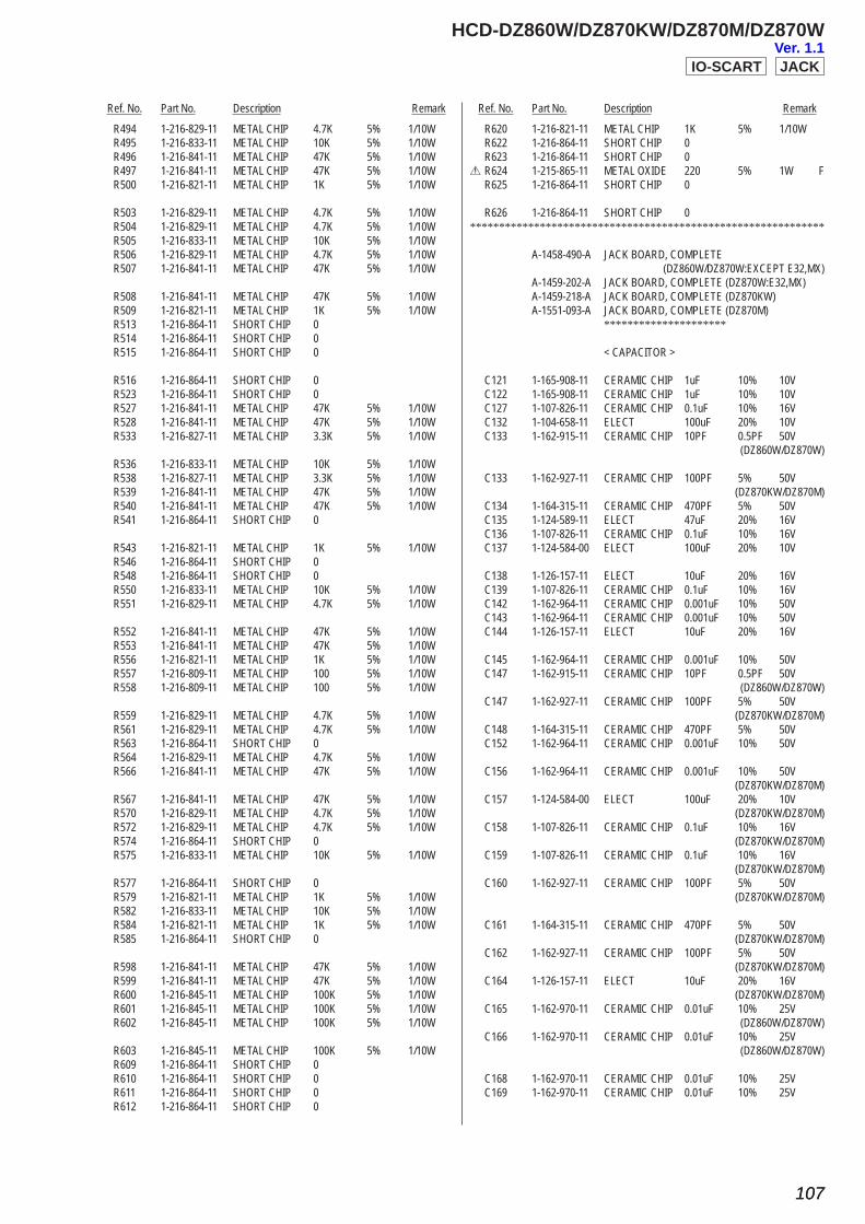
Ref. No. Part No. Description Remark Ref. No. Part No. Description Remark
HCD-DZ860W/DZ870KW/DZ870M/DZ870W
107107
R494 1-216-829-11 METAL CHIP 4.7K 5% 1/10W R495 1-216-833-11 METAL CHIP 10K 5% 1/10W R496 1-216-841-11 METAL CHIP 47K 5% 1/10W R497 1-216-841-11 METAL CHIP 47K 5% 1/10W R500 1-216-821-11 METAL CHIP 1K 5% 1/10W
R503 1-216-829-11 METAL CHIP 4.7K 5% 1/10W R504 1-216-829-11 METAL CHIP 4.7K 5% 1/10W R505 1-216-833-11 METAL CHIP 10K 5% 1/10W R506 1-216-829-11 METAL CHIP 4.7K 5% 1/10W R507 1-216-841-11 METAL CHIP 47K 5% 1/10W
R508 1-216-841-11 METAL CHIP 47K 5% 1/10W R509 1-216-821-11 METAL CHIP 1K 5% 1/10W R513 1-216-864-11 SHORT CHIP 0 R514 1-216-864-11 SHORT CHIP 0 R515 1-216-864-11 SHORT CHIP 0
R516 1-216-864-11 SHORT CHIP 0 R523 1-216-864-11 SHORT CHIP 0 R527 1-216-841-11 METAL CHIP 47K 5% 1/10W R528 1-216-841-11 METAL CHIP 47K 5% 1/10W R533 1-216-827-11 METAL CHIP 3.3K 5% 1/10W
R536 1-216-833-11 METAL CHIP 10K 5% 1/10W R538 1-216-827-11 METAL CHIP 3.3K 5% 1/10W R539 1-216-841-11 METAL CHIP 47K 5% 1/10W R540 1-216-841-11 METAL CHIP 47K 5% 1/10W R541 1-216-864-11 SHORT CHIP 0
R543 1-216-821-11 METAL CHIP 1K 5% 1/10W R546 1-216-864-11 SHORT CHIP 0 R548 1-216-864-11 SHORT CHIP 0 R550 1-216-833-11 METAL CHIP 10K 5% 1/10W R551 1-216-829-11 METAL CHIP 4.7K 5% 1/10W
R552 1-216-841-11 METAL CHIP 47K 5% 1/10W R553 1-216-841-11 METAL CHIP 47K 5% 1/10W R556 1-216-821-11 METAL CHIP 1K 5% 1/10W R557 1-216-809-11 METAL CHIP 100 5% 1/10W R558 1-216-809-11 METAL CHIP 100 5% 1/10W
R559 1-216-829-11 METAL CHIP 4.7K 5% 1/10W R561 1-216-829-11 METAL CHIP 4.7K 5% 1/10W R563 1-216-864-11 SHORT CHIP 0 R564 1-216-829-11 METAL CHIP 4.7K 5% 1/10W R566 1-216-841-11 METAL CHIP 47K 5% 1/10W
R567 1-216-841-11 METAL CHIP 47K 5% 1/10W R570 1-216-829-11 METAL CHIP 4.7K 5% 1/10W R572 1-216-829-11 METAL CHIP 4.7K 5% 1/10W R574 1-216-864-11 SHORT CHIP 0 R575 1-216-833-11 METAL CHIP 10K 5% 1/10W
R577 1-216-864-11 SHORT CHIP 0 R579 1-216-821-11 METAL CHIP 1K 5% 1/10W R582 1-216-833-11 METAL CHIP 10K 5% 1/10W R584 1-216-821-11 METAL CHIP 1K 5% 1/10W R585 1-216-864-11 SHORT CHIP 0
R598 1-216-841-11 METAL CHIP 47K 5% 1/10W R599 1-216-841-11 METAL CHIP 47K 5% 1/10W R600 1-216-845-11 METAL CHIP 100K 5% 1/10W R601 1-216-845-11 METAL CHIP 100K 5% 1/10W R602 1-216-845-11 METAL CHIP 100K 5% 1/10W
R603 1-216-845-11 METAL CHIP 100K 5% 1/10W R609 1-216-864-11 SHORT CHIP 0 R610 1-216-864-11 SHORT CHIP 0 R611 1-216-864-11 SHORT CHIP 0 R612 1-216-864-11 SHORT CHIP 0
R620 1-216-821-11 METAL CHIP 1K 5% 1/10W R622 1-216-864-11 SHORT CHIP 0 R623 1-216-864-11 SHORT CHIP 00 R624 1-215-865-11 METAL OXIDE 220 5% 1W F R625 1-216-864-11 SHORT CHIP 0
R626 1-216-864-11 SHORT CHIP 0*************************************************************
A-1458-490-A JACK BOARD, COMPLETE (DZ860W/DZ870W:EXCEPT E32,MX) A-1459-202-A JACK BOARD, COMPLETE (DZ870W:E32,MX) A-1459-218-A JACK BOARD, COMPLETE (DZ870KW) A-1551-093-A JACK BOARD, COMPLETE (DZ870M) *********************
< CAPACITOR >
C121 1-165-908-11 CERAMIC CHIP 1uF 10% 10V C122 1-165-908-11 CERAMIC CHIP 1uF 10% 10V C127 1-107-826-11 CERAMIC CHIP 0.1uF 10% 16V C132 1-104-658-11 ELECT 100uF 20% 10V C133 1-162-915-11 CERAMIC CHIP 10PF 0.5PF 50V (DZ860W/DZ870W)
C133 1-162-927-11 CERAMIC CHIP 100PF 5% 50V (DZ870KW/DZ870M) C134 1-164-315-11 CERAMIC CHIP 470PF 5% 50V C135 1-124-589-11 ELECT 47uF 20% 16V C136 1-107-826-11 CERAMIC CHIP 0.1uF 10% 16V C137 1-124-584-00 ELECT 100uF 20% 10V
C138 1-126-157-11 ELECT 10uF 20% 16V C139 1-107-826-11 CERAMIC CHIP 0.1uF 10% 16V C142 1-162-964-11 CERAMIC CHIP 0.001uF 10% 50V C143 1-162-964-11 CERAMIC CHIP 0.001uF 10% 50V C144 1-126-157-11 ELECT 10uF 20% 16V
C145 1-162-964-11 CERAMIC CHIP 0.001uF 10% 50V C147 1-162-915-11 CERAMIC CHIP 10PF 0.5PF 50V (DZ860W/DZ870W) C147 1-162-927-11 CERAMIC CHIP 100PF 5% 50V (DZ870KW/DZ870M) C148 1-164-315-11 CERAMIC CHIP 470PF 5% 50V C152 1-162-964-11 CERAMIC CHIP 0.001uF 10% 50V
C156 1-162-964-11 CERAMIC CHIP 0.001uF 10% 50V (DZ870KW/DZ870M) C157 1-124-584-00 ELECT 100uF 20% 10V (DZ870KW/DZ870M) C158 1-107-826-11 CERAMIC CHIP 0.1uF 10% 16V (DZ870KW/DZ870M) C159 1-107-826-11 CERAMIC CHIP 0.1uF 10% 16V (DZ870KW/DZ870M) C160 1-162-927-11 CERAMIC CHIP 100PF 5% 50V (DZ870KW/DZ870M)
C161 1-164-315-11 CERAMIC CHIP 470PF 5% 50V (DZ870KW/DZ870M) C162 1-162-927-11 CERAMIC CHIP 100PF 5% 50V (DZ870KW/DZ870M) C164 1-126-157-11 ELECT 10uF 20% 16V (DZ870KW/DZ870M) C165 1-162-970-11 CERAMIC CHIP 0.01uF 10% 25V (DZ860W/DZ870W) C166 1-162-970-11 CERAMIC CHIP 0.01uF 10% 25V (DZ860W/DZ870W)
C168 1-162-970-11 CERAMIC CHIP 0.01uF 10% 25V C169 1-162-970-11 CERAMIC CHIP 0.01uF 10% 25V
IO-SCART JACKVer. 1.1

Ref. No. Part No. Description Remark Ref. No. Part No. Description Remark
HCD-DZ860W/DZ870KW/DZ870M/DZ870W
108
< CONNECTOR >
CN102 1-779-277-11 CONNECTOR, FFC (LIF(NON-ZIF)) 9P CN103 1-779-287-11 CONNECTOR, FFC (LIF(NON-ZIF)) 19P CN104 1-819-866-11 CONNECTOR, USB (A) (USB) CN105 1-564-721-11 PIN, CONNECTOR (SMALL TYPE) 5P
< DIODE >
D107 6-501-817-01 DIODE MA2J1110GLS0 D108 6-501-579-01 DIODE MC2837 D109 6-501-579-01 DIODE MC2837
< FERRITE BEAD >
FB102 1-500-236-22 BEAD, FERRITE (CHIP) (1608) (EXCEPT DZ870KW/DZ870W:E32,MX) FB103 1-500-236-22 BEAD, FERRITE (CHIP) (1608) (EXCEPT DZ870KW/DZ870W:E32,MX) FB104 1-500-236-22 BEAD, FERRITE (CHIP) (1608) (EXCEPT DZ870KW/DZ870W:E32,MX) FB105 1-500-236-22 BEAD, FERRITE (CHIP) (1608) (DZ860W/DZ870W:EXCEPT E32,MX) FB106 1-500-236-22 BEAD, FERRITE (CHIP) (1608) (DZ860W/DZ870W:EXCEPT E32,MX)
< IC >
IC102 6-705-312-01 IC S-T111B33MC-OGSTFG IC103 8-759-100-96 IC uPC4558G2 IC104 8-759-100-96 IC uPC4558G2 (DZ870KW/DZ870M)
< JACK >
J100 1-819-878-41 JACK (AUDIO IN/MIC1/A.CAL MIC) (DZ870KW/DZ870M) J100 1-819-878-51 JACK (AUDIO IN/A.CAL MIC) (DZ860W/DZ870W) J101 1-819-878-41 JACK (MIC2) (DZ870KW/DZ870M) J101 1-819-878-51 JACK (PHONES) (DZ860W/DZ870W)
< JUMPER RESISTOR >
JR101 1-216-864-11 SHORT CHIP 0 JR102 1-216-864-11 SHORT CHIP 0 JR103 1-216-864-11 SHORT CHIP 0
< TRANSISTOR >
Q101 8-729-038-28 TRANSISTOR RT1N441C-TP-1 Q102 8-729-038-28 TRANSISTOR RT1N441C-TP-1 Q103 8-729-038-11 TRANSISTOR RT1P140C-TP-1 Q104 8-729-027-23 TRANSISTOR DTA114EKA-T146 Q105 8-729-027-23 TRANSISTOR DTA114EKA-T146
Q106 6-550-889-01 TRANSISTOR 2SC5938-T112-1B (DZ860W/DZ870W) Q107 6-550-889-01 TRANSISTOR 2SC5938-T112-1B (DZ860W/DZ870W) Q108 6-550-889-01 TRANSISTOR 2SC5938-T112-1B (DZ860W/DZ870W) Q109 6-550-889-01 TRANSISTOR 2SC5938-T112-1B (DZ860W/DZ870W)
< RESISTOR >
R109 1-216-827-11 METAL CHIP 3.3K 5% 1/10W R110 1-216-833-11 METAL CHIP 10K 5% 1/10W R111 1-216-809-11 METAL CHIP 100 5% 1/10W R112 1-216-809-11 METAL CHIP 100 5% 1/10W R113 1-216-815-11 METAL CHIP 330 5% 1/10W
R114 1-216-815-11 METAL CHIP 330 5% 1/10W R115 1-216-827-11 METAL CHIP 3.3K 5% 1/10W R121 1-216-825-11 METAL CHIP 2.2K 5% 1/10W R122 1-216-825-11 METAL CHIP 2.2K 5% 1/10W R123 1-216-821-11 METAL CHIP 1K 5% 1/10W
R126 1-216-825-11 METAL CHIP 2.2K 5% 1/10W R128 1-216-827-11 METAL CHIP 3.3K 5% 1/10W R129 1-216-801-11 METAL CHIP 22 5% 1/10W (DZ870KW/DZ870M) R129 1-216-811-11 METAL CHIP 150 5% 1/10W (DZ860W/DZ870W) R130 1-216-821-11 METAL CHIP 1K 5% 1/10W
R131 1-216-821-11 METAL CHIP 1K 5% 1/10W R132 1-216-809-11 METAL CHIP 100 5% 1/10W R133 1-216-819-11 METAL CHIP 680 5% 1/10W R134 1-216-837-11 METAL CHIP 22K 5% 1/10W (DZ870KW/DZ870M) R134 1-216-846-11 METAL CHIP 120K 5% 1/10W (DZ860W/DZ870W)
R135 1-216-833-11 METAL CHIP 10K 5% 1/10W R136 1-216-825-11 METAL CHIP 2.2K 5% 1/10W R137 1-216-837-11 METAL CHIP 22K 5% 1/10W R138 1-216-845-11 METAL CHIP 100K 5% 1/10W R139 1-216-825-11 METAL CHIP 2.2K 5% 1/10W
R140 1-216-805-11 METAL CHIP 47 5% 1/10W R141 1-216-827-11 METAL CHIP 3.3K 5% 1/10W R143 1-216-817-11 METAL CHIP 470 5% 1/10W R144 1-216-829-11 METAL CHIP 4.7K 5% 1/10W R145 1-216-845-11 METAL CHIP 100K 5% 1/10W
R146 1-216-817-11 METAL CHIP 470 5% 1/10W R147 1-216-845-11 METAL CHIP 100K 5% 1/10W R148 1-216-837-11 METAL CHIP 22K 5% 1/10W R149 1-216-821-11 METAL CHIP 1K 5% 1/10W R150 1-216-821-11 METAL CHIP 1K 5% 1/10W
R153 1-216-864-11 SHORT CHIP 0 (DZ870KW/DZ870M) R155 1-216-864-11 SHORT CHIP 0 (DZ870KW/DZ870M) R156 1-216-864-11 SHORT CHIP 0 (DZ870KW/DZ870M) R157 1-216-829-11 METAL CHIP 4.7K 5% 1/10W (DZ870KW/DZ870M) R158 1-216-829-11 METAL CHIP 4.7K 5% 1/10W (DZ870KW/DZ870M)
R159 1-216-845-11 METAL CHIP 100K 5% 1/10W (DZ870KW/DZ870M) R160 1-216-837-11 METAL CHIP 22K 5% 1/10W (DZ870KW/DZ870M) R161 1-216-817-11 METAL CHIP 470 5% 1/10W (DZ870KW/DZ870M) R162 1-216-864-11 SHORT CHIP 0 (DZ860W/DZ870W) R163 1-216-821-11 METAL CHIP 1K 5% 1/10W (DZ870KW/DZ870M)
R164 1-216-837-11 METAL CHIP 22K 5% 1/10W (DZ870KW/DZ870M) R165 1-216-829-11 METAL CHIP 4.7K 5% 1/10W (DZ860W/DZ870W) R166 1-216-829-11 METAL CHIP 4.7K 5% 1/10W (DZ860W/DZ870W) R167 1-216-801-11 METAL CHIP 22 5% 1/10W (DZ860W/DZ870W) R168 1-216-801-11 METAL CHIP 22 5% 1/10W (DZ860W/DZ870W)
R169 1-216-829-11 METAL CHIP 4.7K 5% 1/10W (DZ860W/DZ870W)
JACK
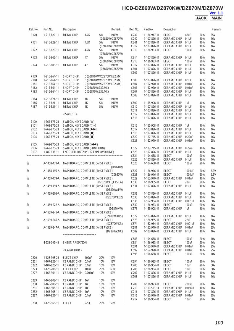
Ref. No. Part No. Description Remark Ref. No. Part No. Description Remark
HCD-DZ860W/DZ870KW/DZ870M/DZ870W
109109
R170 1-216-829-11 METAL CHIP 4.7K 5% 1/10W (DZ860W/DZ870W) R171 1-216-829-11 METAL CHIP 4.7K 5% 1/10W (DZ860W/DZ870W) R172 1-216-829-11 METAL CHIP 4.7K 5% 1/10W (DZ860W/DZ870W) R173 1-216-805-11 METAL CHIP 47 5% 1/10W (DZ860W/DZ870W) R174 1-216-805-11 METAL CHIP 47 5% 1/10W (DZ860W/DZ870W)
R179 1-216-864-11 SHORT CHIP 0 (DZ870KW/DZ870W:E32,MX) R180 1-216-864-11 SHORT CHIP 0 (DZ870KW/DZ870W:E32,MX) R181 1-216-864-11 SHORT CHIP 0 (DZ870KW/DZ870W:E32,MX) R182 1-216-864-11 SHORT CHIP 0 (DZ870W:E32,MX) R183 1-216-864-11 SHORT CHIP 0 (DZ870W:E32,MX)
R184 1-216-821-11 METAL CHIP 1K 5% 1/10W R186 1-216-821-11 METAL CHIP 1K 5% 1/10W R187 1-216-821-11 METAL CHIP 1K 5% 1/10W
< SWITCH >
S100 1-762-875-21 SWITCH, KEYBOARD (A) S101 1-762-875-21 SWITCH, KEYBOARD (H) S102 1-762-875-21 SWITCH, KEYBOARD (>) S103 1-762-875-21 SWITCH, KEYBOARD (x) S104 1-762-875-21 SWITCH, KEYBOARD (X)
S105 1-762-875-21 SWITCH, KEYBOARD (.) S106 1-762-875-21 SWITCH, KEYBOARD (FUNCTION) S107 1-480-136-11 ENCODER, ROTARY (12 TYPE) (VOLUME)*************************************************************
9 A-1458-471-A MAIN BOARD, COMPLETE (for SERVICE) (DZ870M)9 A-1458-495-A MAIN BOARD, COMPLETE (for SERVICE) (DZ860W)9 A-1459-179-A MAIN BOARD, COMPLETE (for SERVICE) (DZ870W:E3,E15,EA)9 A-1459-194-A MAIN BOARD, COMPLETE (for SERVICE) (DZ870W:TW)9 A-1459-205-A MAIN BOARD, COMPLETE (for SERVICE) (DZ870W:E32)
9 A-1459-222-A MAIN BOARD, COMPLETE (for SERVICE) (DZ870KW)9 A-1539-245-A MAIN BOARD, COMPLETE (for SERVICE) (DZ870W:AUS)9 A-1539-246-A MAIN BOARD, COMPLETE (for SERVICE) (DZ870W:KR)9 A-1539-247-A MAIN BOARD, COMPLETE (for SERVICE) (DZ870W:MX) *********************
4-231-099-41 SHEET, RADIATION
< CAPACITOR >
C220 1-128-995-21 ELECT CHIP 100uF 20% 10V C221 1-107-826-11 CERAMIC CHIP 0.1uF 10% 16V C222 1-107-826-11 CERAMIC CHIP 0.1uF 10% 16V C223 1-126-206-11 ELECT CHIP 100uF 20% 6.3V C227 1-162-964-11 CERAMIC CHIP 0.001uF 10% 50V
C229 1-165-908-11 CERAMIC CHIP 1uF 10% 10V C230 1-165-908-11 CERAMIC CHIP 1uF 10% 10V C231 1-165-908-11 CERAMIC CHIP 1uF 10% 10V C232 1-165-908-11 CERAMIC CHIP 1uF 10% 10V C237 1-107-826-11 CERAMIC CHIP 0.1uF 10% 16V
C238 1-126-965-11 ELECT 22uF 20% 50V
C239 1-126-947-11 ELECT 47uF 20% 35V C240 1-107-826-11 CERAMIC CHIP 0.1uF 10% 16V C241 1-107-826-11 CERAMIC CHIP 0.1uF 10% 16V C312 1-107-826-11 CERAMIC CHIP 0.1uF 10% 16V C313 1-126-933-11 ELECT 100uF 20% 16V
C314 1-107-826-11 CERAMIC CHIP 0.1uF 10% 16V C315 1-126-933-11 ELECT 100uF 20% 16V C317 1-107-826-11 CERAMIC CHIP 0.1uF 10% 16V C501 1-107-826-11 CERAMIC CHIP 0.1uF 10% 16V C502 1-107-826-11 CERAMIC CHIP 0.1uF 10% 16V
C503 1-107-826-11 CERAMIC CHIP 0.1uF 10% 16V C504 1-162-970-11 CERAMIC CHIP 0.01uF 10% 25V C505 1-162-970-11 CERAMIC CHIP 0.01uF 10% 25V C507 1-107-826-11 CERAMIC CHIP 0.1uF 10% 16V C508 1-107-826-11 CERAMIC CHIP 0.1uF 10% 16V
C509 1-165-908-11 CERAMIC CHIP 1uF 10% 10V C510 1-107-826-11 CERAMIC CHIP 0.1uF 10% 16V C511 1-107-826-11 CERAMIC CHIP 0.1uF 10% 16V C512 1-107-826-11 CERAMIC CHIP 0.1uF 10% 16V C515 1-107-826-11 CERAMIC CHIP 0.1uF 10% 16V
C516 1-165-908-11 CERAMIC CHIP 1uF 10% 10V C517 1-107-826-11 CERAMIC CHIP 0.1uF 10% 16V C518 1-107-826-11 CERAMIC CHIP 0.1uF 10% 16V C520 1-127-715-11 CERAMIC CHIP 0.22uF 10% 16V C521 1-162-970-11 CERAMIC CHIP 0.01uF 10% 25V
C522 1-127-715-11 CERAMIC CHIP 0.22uF 10% 16V C523 1-107-826-11 CERAMIC CHIP 0.1uF 10% 16V C524 1-104-658-11 ELECT 100uF 20% 10V C525 1-107-826-11 CERAMIC CHIP 0.1uF 10% 16V C526 1-104-658-11 ELECT 100uF 20% 10V
C527 1-126-916-11 ELECT 1000uF 20% 6.3V C528 1-126-916-11 ELECT 1000uF 20% 6.3V C529 1-162-970-11 CERAMIC CHIP 0.01uF 10% 25V C530 1-126-965-11 ELECT 22uF 20% 50V C531 1-107-826-11 CERAMIC CHIP 0.1uF 10% 16V
C532 1-107-826-11 CERAMIC CHIP 0.1uF 10% 16V C533 1-107-826-11 CERAMIC CHIP 0.1uF 10% 16V C538 1-162-964-11 CERAMIC CHIP 0.001uF 10% 50V C539 1-126-933-11 ELECT 100uF 20% 16V C571 1-165-908-11 CERAMIC CHIP 1uF 10% 10V
C572 1-107-826-11 CERAMIC CHIP 0.1uF 10% 16V C573 1-126-965-11 ELECT 22uF 20% 50V C574 1-162-964-11 CERAMIC CHIP 0.001uF 10% 50V C581 1-162-970-11 CERAMIC CHIP 0.01uF 10% 25V C582 1-107-826-11 CERAMIC CHIP 0.1uF 10% 16V
C583 1-104-658-11 ELECT 100uF 20% 10V C584 1-126-933-11 ELECT 100uF 20% 16V C591 1-162-970-11 CERAMIC CHIP 0.01uF 10% 25V C592 1-162-970-11 CERAMIC CHIP 0.01uF 10% 25V C593 1-104-658-11 ELECT 100uF 20% 10V
C594 1-126-933-11 ELECT 100uF 20% 16V C705 1-126-964-11 ELECT 10uF 20% 50V C706 1-126-964-11 ELECT 10uF 20% 50V C707 1-107-826-11 CERAMIC CHIP 0.1uF 10% 16V C708 1-107-826-11 CERAMIC CHIP 0.1uF 10% 16V
C709 1-126-923-11 ELECT 220uF 20% 10V C710 1-110-563-11 CERAMIC CHIP 0.068uF 10% 16V C711 1-107-826-11 CERAMIC CHIP 0.1uF 10% 16V C716 1-162-970-11 CERAMIC CHIP 0.01uF 10% 25V C717 1-126-964-11 ELECT 10uF 20% 50V
MAINJACKVer. 1.1
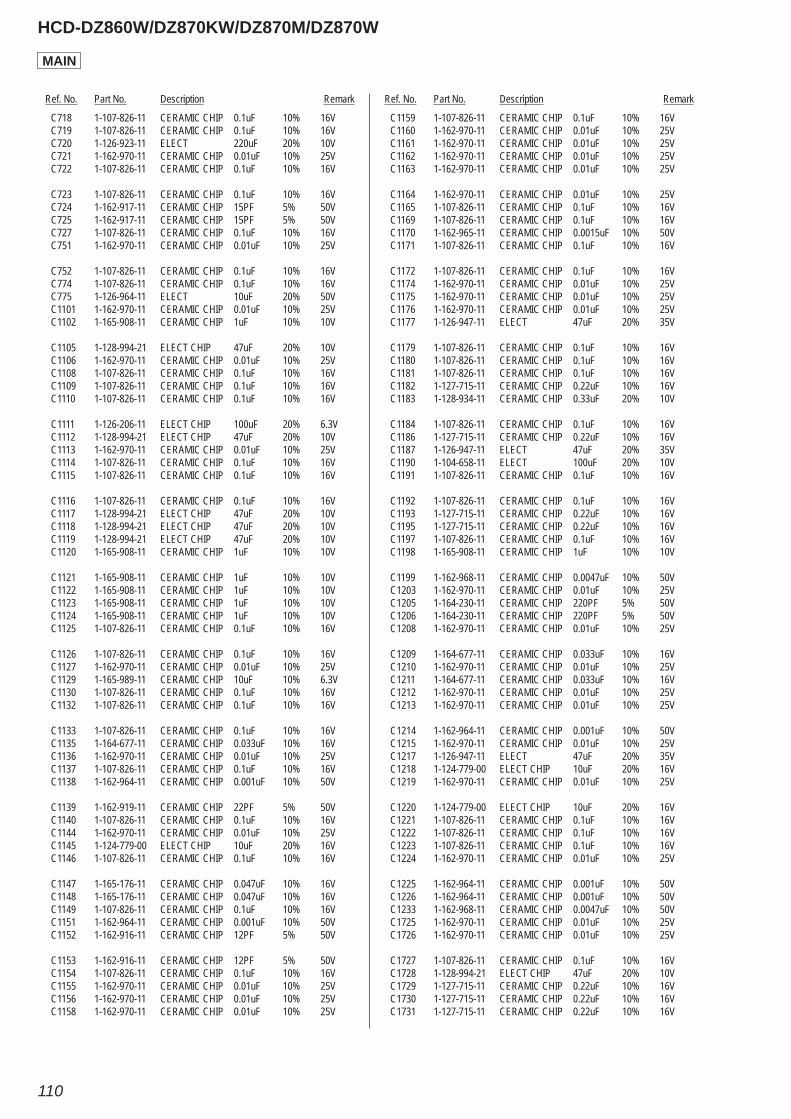
Ref. No. Part No. Description Remark Ref. No. Part No. Description Remark
HCD-DZ860W/DZ870KW/DZ870M/DZ870W
110
C718 1-107-826-11 CERAMIC CHIP 0.1uF 10% 16V C719 1-107-826-11 CERAMIC CHIP 0.1uF 10% 16V C720 1-126-923-11 ELECT 220uF 20% 10V C721 1-162-970-11 CERAMIC CHIP 0.01uF 10% 25V C722 1-107-826-11 CERAMIC CHIP 0.1uF 10% 16V
C723 1-107-826-11 CERAMIC CHIP 0.1uF 10% 16V C724 1-162-917-11 CERAMIC CHIP 15PF 5% 50V C725 1-162-917-11 CERAMIC CHIP 15PF 5% 50V C727 1-107-826-11 CERAMIC CHIP 0.1uF 10% 16V C751 1-162-970-11 CERAMIC CHIP 0.01uF 10% 25V
C752 1-107-826-11 CERAMIC CHIP 0.1uF 10% 16V C774 1-107-826-11 CERAMIC CHIP 0.1uF 10% 16V C775 1-126-964-11 ELECT 10uF 20% 50V C1101 1-162-970-11 CERAMIC CHIP 0.01uF 10% 25V C1102 1-165-908-11 CERAMIC CHIP 1uF 10% 10V
C1105 1-128-994-21 ELECT CHIP 47uF 20% 10V C1106 1-162-970-11 CERAMIC CHIP 0.01uF 10% 25V C1108 1-107-826-11 CERAMIC CHIP 0.1uF 10% 16V C1109 1-107-826-11 CERAMIC CHIP 0.1uF 10% 16V C1110 1-107-826-11 CERAMIC CHIP 0.1uF 10% 16V
C1111 1-126-206-11 ELECT CHIP 100uF 20% 6.3V C1112 1-128-994-21 ELECT CHIP 47uF 20% 10V C1113 1-162-970-11 CERAMIC CHIP 0.01uF 10% 25V C1114 1-107-826-11 CERAMIC CHIP 0.1uF 10% 16V C1115 1-107-826-11 CERAMIC CHIP 0.1uF 10% 16V
C1116 1-107-826-11 CERAMIC CHIP 0.1uF 10% 16V C1117 1-128-994-21 ELECT CHIP 47uF 20% 10V C1118 1-128-994-21 ELECT CHIP 47uF 20% 10V C1119 1-128-994-21 ELECT CHIP 47uF 20% 10V C1120 1-165-908-11 CERAMIC CHIP 1uF 10% 10V
C1121 1-165-908-11 CERAMIC CHIP 1uF 10% 10V C1122 1-165-908-11 CERAMIC CHIP 1uF 10% 10V C1123 1-165-908-11 CERAMIC CHIP 1uF 10% 10V C1124 1-165-908-11 CERAMIC CHIP 1uF 10% 10V C1125 1-107-826-11 CERAMIC CHIP 0.1uF 10% 16V
C1126 1-107-826-11 CERAMIC CHIP 0.1uF 10% 16V C1127 1-162-970-11 CERAMIC CHIP 0.01uF 10% 25V C1129 1-165-989-11 CERAMIC CHIP 10uF 10% 6.3V C1130 1-107-826-11 CERAMIC CHIP 0.1uF 10% 16V C1132 1-107-826-11 CERAMIC CHIP 0.1uF 10% 16V
C1133 1-107-826-11 CERAMIC CHIP 0.1uF 10% 16V C1135 1-164-677-11 CERAMIC CHIP 0.033uF 10% 16V C1136 1-162-970-11 CERAMIC CHIP 0.01uF 10% 25V C1137 1-107-826-11 CERAMIC CHIP 0.1uF 10% 16V C1138 1-162-964-11 CERAMIC CHIP 0.001uF 10% 50V
C1139 1-162-919-11 CERAMIC CHIP 22PF 5% 50V C1140 1-107-826-11 CERAMIC CHIP 0.1uF 10% 16V C1144 1-162-970-11 CERAMIC CHIP 0.01uF 10% 25V C1145 1-124-779-00 ELECT CHIP 10uF 20% 16V C1146 1-107-826-11 CERAMIC CHIP 0.1uF 10% 16V
C1147 1-165-176-11 CERAMIC CHIP 0.047uF 10% 16V C1148 1-165-176-11 CERAMIC CHIP 0.047uF 10% 16V C1149 1-107-826-11 CERAMIC CHIP 0.1uF 10% 16V C1151 1-162-964-11 CERAMIC CHIP 0.001uF 10% 50V C1152 1-162-916-11 CERAMIC CHIP 12PF 5% 50V
C1153 1-162-916-11 CERAMIC CHIP 12PF 5% 50V C1154 1-107-826-11 CERAMIC CHIP 0.1uF 10% 16V C1155 1-162-970-11 CERAMIC CHIP 0.01uF 10% 25V C1156 1-162-970-11 CERAMIC CHIP 0.01uF 10% 25V C1158 1-162-970-11 CERAMIC CHIP 0.01uF 10% 25V
C1159 1-107-826-11 CERAMIC CHIP 0.1uF 10% 16V C1160 1-162-970-11 CERAMIC CHIP 0.01uF 10% 25V C1161 1-162-970-11 CERAMIC CHIP 0.01uF 10% 25V C1162 1-162-970-11 CERAMIC CHIP 0.01uF 10% 25V C1163 1-162-970-11 CERAMIC CHIP 0.01uF 10% 25V
C1164 1-162-970-11 CERAMIC CHIP 0.01uF 10% 25V C1165 1-107-826-11 CERAMIC CHIP 0.1uF 10% 16V C1169 1-107-826-11 CERAMIC CHIP 0.1uF 10% 16V C1170 1-162-965-11 CERAMIC CHIP 0.0015uF 10% 50V C1171 1-107-826-11 CERAMIC CHIP 0.1uF 10% 16V
C1172 1-107-826-11 CERAMIC CHIP 0.1uF 10% 16V C1174 1-162-970-11 CERAMIC CHIP 0.01uF 10% 25V C1175 1-162-970-11 CERAMIC CHIP 0.01uF 10% 25V C1176 1-162-970-11 CERAMIC CHIP 0.01uF 10% 25V C1177 1-126-947-11 ELECT 47uF 20% 35V
C1179 1-107-826-11 CERAMIC CHIP 0.1uF 10% 16V C1180 1-107-826-11 CERAMIC CHIP 0.1uF 10% 16V C1181 1-107-826-11 CERAMIC CHIP 0.1uF 10% 16V C1182 1-127-715-11 CERAMIC CHIP 0.22uF 10% 16V C1183 1-128-934-11 CERAMIC CHIP 0.33uF 20% 10V
C1184 1-107-826-11 CERAMIC CHIP 0.1uF 10% 16V C1186 1-127-715-11 CERAMIC CHIP 0.22uF 10% 16V C1187 1-126-947-11 ELECT 47uF 20% 35V C1190 1-104-658-11 ELECT 100uF 20% 10V C1191 1-107-826-11 CERAMIC CHIP 0.1uF 10% 16V
C1192 1-107-826-11 CERAMIC CHIP 0.1uF 10% 16V C1193 1-127-715-11 CERAMIC CHIP 0.22uF 10% 16V C1195 1-127-715-11 CERAMIC CHIP 0.22uF 10% 16V C1197 1-107-826-11 CERAMIC CHIP 0.1uF 10% 16V C1198 1-165-908-11 CERAMIC CHIP 1uF 10% 10V
C1199 1-162-968-11 CERAMIC CHIP 0.0047uF 10% 50V C1203 1-162-970-11 CERAMIC CHIP 0.01uF 10% 25V C1205 1-164-230-11 CERAMIC CHIP 220PF 5% 50V C1206 1-164-230-11 CERAMIC CHIP 220PF 5% 50V C1208 1-162-970-11 CERAMIC CHIP 0.01uF 10% 25V
C1209 1-164-677-11 CERAMIC CHIP 0.033uF 10% 16V C1210 1-162-970-11 CERAMIC CHIP 0.01uF 10% 25V C1211 1-164-677-11 CERAMIC CHIP 0.033uF 10% 16V C1212 1-162-970-11 CERAMIC CHIP 0.01uF 10% 25V C1213 1-162-970-11 CERAMIC CHIP 0.01uF 10% 25V
C1214 1-162-964-11 CERAMIC CHIP 0.001uF 10% 50V C1215 1-162-970-11 CERAMIC CHIP 0.01uF 10% 25V C1217 1-126-947-11 ELECT 47uF 20% 35V C1218 1-124-779-00 ELECT CHIP 10uF 20% 16V C1219 1-162-970-11 CERAMIC CHIP 0.01uF 10% 25V
C1220 1-124-779-00 ELECT CHIP 10uF 20% 16V C1221 1-107-826-11 CERAMIC CHIP 0.1uF 10% 16V C1222 1-107-826-11 CERAMIC CHIP 0.1uF 10% 16V C1223 1-107-826-11 CERAMIC CHIP 0.1uF 10% 16V C1224 1-162-970-11 CERAMIC CHIP 0.01uF 10% 25V
C1225 1-162-964-11 CERAMIC CHIP 0.001uF 10% 50V C1226 1-162-964-11 CERAMIC CHIP 0.001uF 10% 50V C1233 1-162-968-11 CERAMIC CHIP 0.0047uF 10% 50V C1725 1-162-970-11 CERAMIC CHIP 0.01uF 10% 25V C1726 1-162-970-11 CERAMIC CHIP 0.01uF 10% 25V
C1727 1-107-826-11 CERAMIC CHIP 0.1uF 10% 16V C1728 1-128-994-21 ELECT CHIP 47uF 20% 10V C1729 1-127-715-11 CERAMIC CHIP 0.22uF 10% 16V C1730 1-127-715-11 CERAMIC CHIP 0.22uF 10% 16V C1731 1-127-715-11 CERAMIC CHIP 0.22uF 10% 16V
MAIN
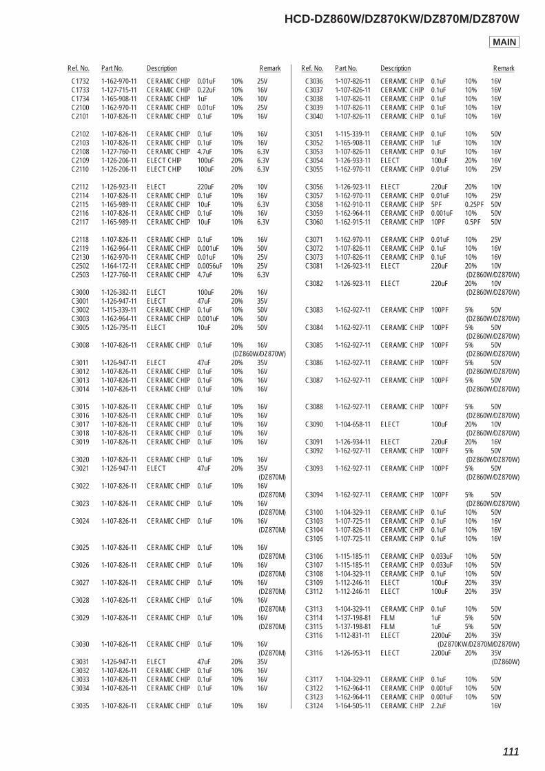
Ref. No. Part No. Description Remark Ref. No. Part No. Description Remark
HCD-DZ860W/DZ870KW/DZ870M/DZ870W
111111
C1732 1-162-970-11 CERAMIC CHIP 0.01uF 10% 25V C1733 1-127-715-11 CERAMIC CHIP 0.22uF 10% 16V C1734 1-165-908-11 CERAMIC CHIP 1uF 10% 10V C2100 1-162-970-11 CERAMIC CHIP 0.01uF 10% 25V C2101 1-107-826-11 CERAMIC CHIP 0.1uF 10% 16V
C2102 1-107-826-11 CERAMIC CHIP 0.1uF 10% 16V C2103 1-107-826-11 CERAMIC CHIP 0.1uF 10% 16V C2108 1-127-760-11 CERAMIC CHIP 4.7uF 10% 6.3V C2109 1-126-206-11 ELECT CHIP 100uF 20% 6.3V C2110 1-126-206-11 ELECT CHIP 100uF 20% 6.3V
C2112 1-126-923-11 ELECT 220uF 20% 10V C2114 1-107-826-11 CERAMIC CHIP 0.1uF 10% 16V C2115 1-165-989-11 CERAMIC CHIP 10uF 10% 6.3V C2116 1-107-826-11 CERAMIC CHIP 0.1uF 10% 16V C2117 1-165-989-11 CERAMIC CHIP 10uF 10% 6.3V
C2118 1-107-826-11 CERAMIC CHIP 0.1uF 10% 16V C2119 1-162-964-11 CERAMIC CHIP 0.001uF 10% 50V C2130 1-162-970-11 CERAMIC CHIP 0.01uF 10% 25V C2502 1-164-172-11 CERAMIC CHIP 0.0056uF 10% 25V C2503 1-127-760-11 CERAMIC CHIP 4.7uF 10% 6.3V
C3000 1-126-382-11 ELECT 100uF 20% 16V C3001 1-126-947-11 ELECT 47uF 20% 35V C3002 1-115-339-11 CERAMIC CHIP 0.1uF 10% 50V C3003 1-162-964-11 CERAMIC CHIP 0.001uF 10% 50V C3005 1-126-795-11 ELECT 10uF 20% 50V
C3008 1-107-826-11 CERAMIC CHIP 0.1uF 10% 16V (DZ860W/DZ870W) C3011 1-126-947-11 ELECT 47uF 20% 35V C3012 1-107-826-11 CERAMIC CHIP 0.1uF 10% 16V C3013 1-107-826-11 CERAMIC CHIP 0.1uF 10% 16V C3014 1-107-826-11 CERAMIC CHIP 0.1uF 10% 16V
C3015 1-107-826-11 CERAMIC CHIP 0.1uF 10% 16V C3016 1-107-826-11 CERAMIC CHIP 0.1uF 10% 16V C3017 1-107-826-11 CERAMIC CHIP 0.1uF 10% 16V C3018 1-107-826-11 CERAMIC CHIP 0.1uF 10% 16V C3019 1-107-826-11 CERAMIC CHIP 0.1uF 10% 16V
C3020 1-107-826-11 CERAMIC CHIP 0.1uF 10% 16V C3021 1-126-947-11 ELECT 47uF 20% 35V (DZ870M) C3022 1-107-826-11 CERAMIC CHIP 0.1uF 10% 16V (DZ870M) C3023 1-107-826-11 CERAMIC CHIP 0.1uF 10% 16V (DZ870M) C3024 1-107-826-11 CERAMIC CHIP 0.1uF 10% 16V (DZ870M)
C3025 1-107-826-11 CERAMIC CHIP 0.1uF 10% 16V (DZ870M) C3026 1-107-826-11 CERAMIC CHIP 0.1uF 10% 16V (DZ870M) C3027 1-107-826-11 CERAMIC CHIP 0.1uF 10% 16V (DZ870M) C3028 1-107-826-11 CERAMIC CHIP 0.1uF 10% 16V (DZ870M) C3029 1-107-826-11 CERAMIC CHIP 0.1uF 10% 16V (DZ870M)
C3030 1-107-826-11 CERAMIC CHIP 0.1uF 10% 16V (DZ870M) C3031 1-126-947-11 ELECT 47uF 20% 35V C3032 1-107-826-11 CERAMIC CHIP 0.1uF 10% 16V C3033 1-107-826-11 CERAMIC CHIP 0.1uF 10% 16V C3034 1-107-826-11 CERAMIC CHIP 0.1uF 10% 16V
C3035 1-107-826-11 CERAMIC CHIP 0.1uF 10% 16V
C3036 1-107-826-11 CERAMIC CHIP 0.1uF 10% 16V C3037 1-107-826-11 CERAMIC CHIP 0.1uF 10% 16V C3038 1-107-826-11 CERAMIC CHIP 0.1uF 10% 16V C3039 1-107-826-11 CERAMIC CHIP 0.1uF 10% 16V C3040 1-107-826-11 CERAMIC CHIP 0.1uF 10% 16V
C3051 1-115-339-11 CERAMIC CHIP 0.1uF 10% 50V C3052 1-165-908-11 CERAMIC CHIP 1uF 10% 10V C3053 1-107-826-11 CERAMIC CHIP 0.1uF 10% 16V C3054 1-126-933-11 ELECT 100uF 20% 16V C3055 1-162-970-11 CERAMIC CHIP 0.01uF 10% 25V
C3056 1-126-923-11 ELECT 220uF 20% 10V C3057 1-162-970-11 CERAMIC CHIP 0.01uF 10% 25V C3058 1-162-910-11 CERAMIC CHIP 5PF 0.25PF 50V C3059 1-162-964-11 CERAMIC CHIP 0.001uF 10% 50V C3060 1-162-915-11 CERAMIC CHIP 10PF 0.5PF 50V
C3071 1-162-970-11 CERAMIC CHIP 0.01uF 10% 25V C3072 1-107-826-11 CERAMIC CHIP 0.1uF 10% 16V C3073 1-107-826-11 CERAMIC CHIP 0.1uF 10% 16V C3081 1-126-923-11 ELECT 220uF 20% 10V (DZ860W/DZ870W) C3082 1-126-923-11 ELECT 220uF 20% 10V (DZ860W/DZ870W)
C3083 1-162-927-11 CERAMIC CHIP 100PF 5% 50V (DZ860W/DZ870W) C3084 1-162-927-11 CERAMIC CHIP 100PF 5% 50V (DZ860W/DZ870W) C3085 1-162-927-11 CERAMIC CHIP 100PF 5% 50V (DZ860W/DZ870W) C3086 1-162-927-11 CERAMIC CHIP 100PF 5% 50V (DZ860W/DZ870W) C3087 1-162-927-11 CERAMIC CHIP 100PF 5% 50V (DZ860W/DZ870W)
C3088 1-162-927-11 CERAMIC CHIP 100PF 5% 50V (DZ860W/DZ870W) C3090 1-104-658-11 ELECT 100uF 20% 10V (DZ860W/DZ870W) C3091 1-126-934-11 ELECT 220uF 20% 16V C3092 1-162-927-11 CERAMIC CHIP 100PF 5% 50V (DZ860W/DZ870W) C3093 1-162-927-11 CERAMIC CHIP 100PF 5% 50V (DZ860W/DZ870W)
C3094 1-162-927-11 CERAMIC CHIP 100PF 5% 50V (DZ860W/DZ870W) C3100 1-104-329-11 CERAMIC CHIP 0.1uF 10% 50V C3103 1-107-725-11 CERAMIC CHIP 0.1uF 10% 16V C3104 1-107-826-11 CERAMIC CHIP 0.1uF 10% 16V C3105 1-107-725-11 CERAMIC CHIP 0.1uF 10% 16V
C3106 1-115-185-11 CERAMIC CHIP 0.033uF 10% 50V C3107 1-115-185-11 CERAMIC CHIP 0.033uF 10% 50V C3108 1-104-329-11 CERAMIC CHIP 0.1uF 10% 50V C3109 1-112-246-11 ELECT 100uF 20% 35V C3112 1-112-246-11 ELECT 100uF 20% 35V
C3113 1-104-329-11 CERAMIC CHIP 0.1uF 10% 50V C3114 1-137-198-81 FILM 1uF 5% 50V C3115 1-137-198-81 FILM 1uF 5% 50V C3116 1-112-831-11 ELECT 2200uF 20% 35V (DZ870KW/DZ870M/DZ870W) C3116 1-126-953-11 ELECT 2200uF 20% 35V (DZ860W)
C3117 1-104-329-11 CERAMIC CHIP 0.1uF 10% 50V C3122 1-162-964-11 CERAMIC CHIP 0.001uF 10% 50V C3123 1-162-964-11 CERAMIC CHIP 0.001uF 10% 50V C3124 1-164-505-11 CERAMIC CHIP 2.2uF 16V
MAIN
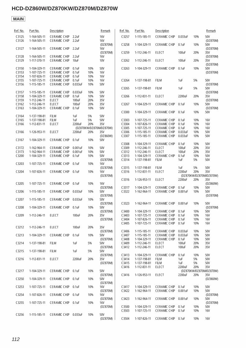
Ref. No. Part No. Description Remark Ref. No. Part No. Description Remark
HCD-DZ860W/DZ870KW/DZ870M/DZ870W
112
C3125 1-164-505-11 CERAMIC CHIP 2.2uF 16V C3126 1-164-505-11 CERAMIC CHIP 2.2uF 16V (DZ870M) C3127 1-164-505-11 CERAMIC CHIP 2.2uF 16V (DZ870M) C3128 1-164-505-11 CERAMIC CHIP 2.2uF 16V C3129 1-117-370-11 CERAMIC CHIP 10uF 10V
C3150 1-104-329-11 CERAMIC CHIP 0.1uF 10% 50V C3153 1-107-725-11 CERAMIC CHIP 0.1uF 10% 16V C3154 1-107-826-11 CERAMIC CHIP 0.1uF 10% 16V C3155 1-107-725-11 CERAMIC CHIP 0.1uF 10% 16V C3156 1-115-185-11 CERAMIC CHIP 0.033uF 10% 50V
C3157 1-115-185-11 CERAMIC CHIP 0.033uF 10% 50V C3158 1-104-329-11 CERAMIC CHIP 0.1uF 10% 50V C3159 1-112-246-11 ELECT 100uF 20% 35V C3162 1-112-246-11 ELECT 100uF 20% 35V C3163 1-104-329-11 CERAMIC CHIP 0.1uF 10% 50V
C3164 1-137-198-81 FILM 1uF 5% 50V C3165 1-137-198-81 FILM 1uF 5% 50V C3166 1-112-831-11 ELECT 2200uF 20% 35V (DZ870KW/DZ870M/DZ870W) C3166 1-126-953-11 ELECT 2200uF 20% 35V (DZ860W) C3167 1-104-329-11 CERAMIC CHIP 0.1uF 10% 50V
C3172 1-162-964-11 CERAMIC CHIP 0.001uF 10% 50V C3173 1-162-964-11 CERAMIC CHIP 0.001uF 10% 50V C3200 1-104-329-11 CERAMIC CHIP 0.1uF 10% 50V (DZ870M) C3203 1-107-725-11 CERAMIC CHIP 0.1uF 10% 16V (DZ870M) C3204 1-107-826-11 CERAMIC CHIP 0.1uF 10% 16V (DZ870M)
C3205 1-107-725-11 CERAMIC CHIP 0.1uF 10% 16V (DZ870M) C3206 1-115-185-11 CERAMIC CHIP 0.033uF 10% 50V (DZ870M) C3207 1-115-185-11 CERAMIC CHIP 0.033uF 10% 50V (DZ870M) C3208 1-104-329-11 CERAMIC CHIP 0.1uF 10% 50V (DZ870M) C3209 1-112-246-11 ELECT 100uF 20% 35V (DZ870M)
C3212 1-112-246-11 ELECT 100uF 20% 35V (DZ870M) C3213 1-104-329-11 CERAMIC CHIP 0.1uF 10% 50V (DZ870M) C3214 1-137-198-81 FILM 1uF 5% 50V (DZ870M) C3215 1-137-198-81 FILM 1uF 5% 50V (DZ870M) C3216 1-112-831-11 ELECT 2200uF 20% 35V (DZ870M)
C3217 1-104-329-11 CERAMIC CHIP 0.1uF 10% 50V (DZ870M) C3250 1-104-329-11 CERAMIC CHIP 0.1uF 10% 50V (DZ870M) C3253 1-107-725-11 CERAMIC CHIP 0.1uF 10% 16V (DZ870M) C3254 1-107-826-11 CERAMIC CHIP 0.1uF 10% 16V (DZ870M) C3255 1-107-725-11 CERAMIC CHIP 0.1uF 10% 16V (DZ870M)
C3256 1-115-185-11 CERAMIC CHIP 0.033uF 10% 50V (DZ870M)
C3257 1-115-185-11 CERAMIC CHIP 0.033uF 10% 50V (DZ870M) C3258 1-104-329-11 CERAMIC CHIP 0.1uF 10% 50V (DZ870M) C3259 1-112-246-11 ELECT 100uF 20% 35V (DZ870M) C3262 1-112-246-11 ELECT 100uF 20% 35V (DZ870M) C3263 1-104-329-11 CERAMIC CHIP 0.1uF 10% 50V (DZ870M)
C3264 1-137-198-81 FILM 1uF 5% 50V (DZ870M) C3265 1-137-198-81 FILM 1uF 5% 50V (DZ870M) C3266 1-112-831-11 ELECT 2200uF 20% 35V (DZ870M) C3267 1-104-329-11 CERAMIC CHIP 0.1uF 10% 50V (DZ870M) C3300 1-104-329-11 CERAMIC CHIP 0.1uF 10% 50V
C3303 1-107-725-11 CERAMIC CHIP 0.1uF 10% 16V C3304 1-107-826-11 CERAMIC CHIP 0.1uF 10% 16V C3305 1-107-725-11 CERAMIC CHIP 0.1uF 10% 16V C3306 1-115-185-11 CERAMIC CHIP 0.033uF 10% 50V C3307 1-115-185-11 CERAMIC CHIP 0.033uF 10% 50V
C3308 1-104-329-11 CERAMIC CHIP 0.1uF 10% 50V C3309 1-112-246-11 ELECT 100uF 20% 35V C3312 1-112-246-11 ELECT 100uF 20% 35V C3313 1-104-329-11 CERAMIC CHIP 0.1uF 10% 50V C3314 1-137-198-81 FILM 1uF 5% 50V
C3315 1-137-198-81 FILM 1uF 5% 50V C3316 1-112-831-11 ELECT 2200uF 20% 35V (DZ870KW/DZ870M/DZ870W) C3316 1-126-953-11 ELECT 2200uF 20% 35V (DZ860W) C3317 1-104-329-11 CERAMIC CHIP 0.1uF 10% 50V C3322 1-162-964-11 CERAMIC CHIP 0.001uF 10% 50V (DZ870M)
C3323 1-162-964-11 CERAMIC CHIP 0.001uF 10% 50V (DZ870M) C3400 1-104-329-11 CERAMIC CHIP 0.1uF 10% 50V C3403 1-107-725-11 CERAMIC CHIP 0.1uF 10% 16V C3404 1-107-826-11 CERAMIC CHIP 0.1uF 10% 16V C3405 1-107-725-11 CERAMIC CHIP 0.1uF 10% 16V
C3406 1-115-185-11 CERAMIC CHIP 0.033uF 10% 50V C3407 1-115-185-11 CERAMIC CHIP 0.033uF 10% 50V C3408 1-104-329-11 CERAMIC CHIP 0.1uF 10% 50V C3409 1-112-246-11 ELECT 100uF 20% 35V C3412 1-112-246-11 ELECT 100uF 20% 35V
C3413 1-104-329-11 CERAMIC CHIP 0.1uF 10% 50V C3414 1-137-198-81 FILM 1uF 5% 50V C3415 1-137-198-81 FILM 1uF 5% 50V C3416 1-112-831-11 ELECT 2200uF 20% 35V (DZ870KW/DZ870M/DZ870W) C3416 1-126-953-11 ELECT 2200uF 20% 35V (DZ860W)
C3417 1-104-329-11 CERAMIC CHIP 0.1uF 10% 50V C3422 1-162-964-11 CERAMIC CHIP 0.001uF 10% 50V (DZ870M) C3423 1-162-964-11 CERAMIC CHIP 0.001uF 10% 50V (DZ870M) C3500 1-104-329-11 CERAMIC CHIP 0.1uF 10% 50V C3503 1-107-725-11 CERAMIC CHIP 0.1uF 10% 16V
C3504 1-107-826-11 CERAMIC CHIP 0.1uF 10% 16V
MAIN
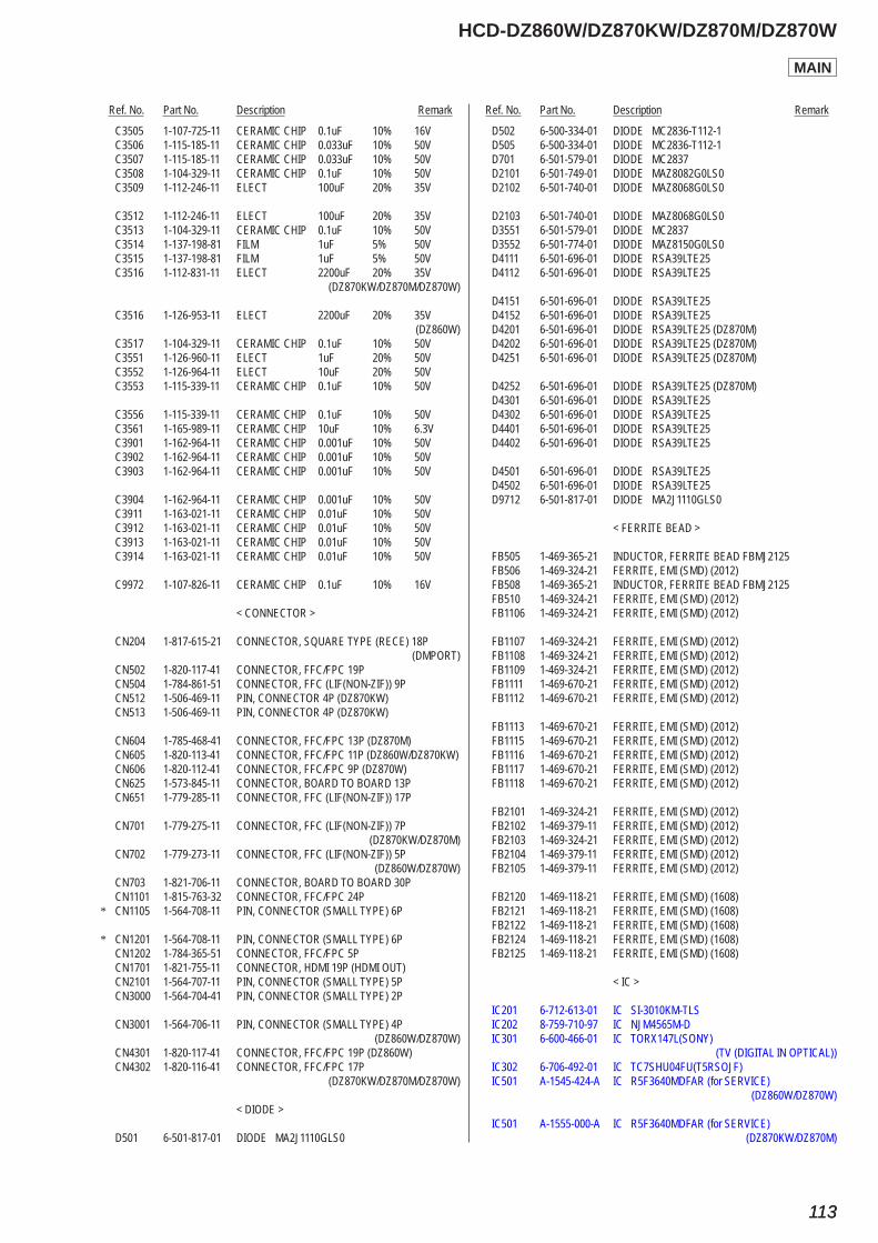
Ref. No. Part No. Description Remark Ref. No. Part No. Description Remark
HCD-DZ860W/DZ870KW/DZ870M/DZ870W
113113
C3505 1-107-725-11 CERAMIC CHIP 0.1uF 10% 16V C3506 1-115-185-11 CERAMIC CHIP 0.033uF 10% 50V C3507 1-115-185-11 CERAMIC CHIP 0.033uF 10% 50V C3508 1-104-329-11 CERAMIC CHIP 0.1uF 10% 50V C3509 1-112-246-11 ELECT 100uF 20% 35V
C3512 1-112-246-11 ELECT 100uF 20% 35V C3513 1-104-329-11 CERAMIC CHIP 0.1uF 10% 50V C3514 1-137-198-81 FILM 1uF 5% 50V C3515 1-137-198-81 FILM 1uF 5% 50V C3516 1-112-831-11 ELECT 2200uF 20% 35V (DZ870KW/DZ870M/DZ870W)
C3516 1-126-953-11 ELECT 2200uF 20% 35V (DZ860W) C3517 1-104-329-11 CERAMIC CHIP 0.1uF 10% 50V C3551 1-126-960-11 ELECT 1uF 20% 50V C3552 1-126-964-11 ELECT 10uF 20% 50V C3553 1-115-339-11 CERAMIC CHIP 0.1uF 10% 50V
C3556 1-115-339-11 CERAMIC CHIP 0.1uF 10% 50V C3561 1-165-989-11 CERAMIC CHIP 10uF 10% 6.3V C3901 1-162-964-11 CERAMIC CHIP 0.001uF 10% 50V C3902 1-162-964-11 CERAMIC CHIP 0.001uF 10% 50V C3903 1-162-964-11 CERAMIC CHIP 0.001uF 10% 50V
C3904 1-162-964-11 CERAMIC CHIP 0.001uF 10% 50V C3911 1-163-021-11 CERAMIC CHIP 0.01uF 10% 50V C3912 1-163-021-11 CERAMIC CHIP 0.01uF 10% 50V C3913 1-163-021-11 CERAMIC CHIP 0.01uF 10% 50V C3914 1-163-021-11 CERAMIC CHIP 0.01uF 10% 50V
C9972 1-107-826-11 CERAMIC CHIP 0.1uF 10% 16V
< CONNECTOR >
CN204 1-817-615-21 CONNECTOR, SQUARE TYPE (RECE) 18P (DMPORT) CN502 1-820-117-41 CONNECTOR, FFC/FPC 19P CN504 1-784-861-51 CONNECTOR, FFC (LIF(NON-ZIF)) 9P CN512 1-506-469-11 PIN, CONNECTOR 4P (DZ870KW) CN513 1-506-469-11 PIN, CONNECTOR 4P (DZ870KW)
CN604 1-785-468-41 CONNECTOR, FFC/FPC 13P (DZ870M) CN605 1-820-113-41 CONNECTOR, FFC/FPC 11P (DZ860W/DZ870KW) CN606 1-820-112-41 CONNECTOR, FFC/FPC 9P (DZ870W) CN625 1-573-845-11 CONNECTOR, BOARD TO BOARD 13P CN651 1-779-285-11 CONNECTOR, FFC (LIF(NON-ZIF)) 17P
CN701 1-779-275-11 CONNECTOR, FFC (LIF(NON-ZIF)) 7P (DZ870KW/DZ870M) CN702 1-779-273-11 CONNECTOR, FFC (LIF(NON-ZIF)) 5P (DZ860W/DZ870W) CN703 1-821-706-11 CONNECTOR, BOARD TO BOARD 30P CN1101 1-815-763-32 CONNECTOR, FFC/FPC 24P* CN1105 1-564-708-11 PIN, CONNECTOR (SMALL TYPE) 6P
* CN1201 1-564-708-11 PIN, CONNECTOR (SMALL TYPE) 6P CN1202 1-784-365-51 CONNECTOR, FFC/FPC 5P CN1701 1-821-755-11 CONNECTOR, HDMI 19P (HDMI OUT) CN2101 1-564-707-11 PIN, CONNECTOR (SMALL TYPE) 5P CN3000 1-564-704-41 PIN, CONNECTOR (SMALL TYPE) 2P
CN3001 1-564-706-11 PIN, CONNECTOR (SMALL TYPE) 4P (DZ860W/DZ870W) CN4301 1-820-117-41 CONNECTOR, FFC/FPC 19P (DZ860W) CN4302 1-820-116-41 CONNECTOR, FFC/FPC 17P (DZ870KW/DZ870M/DZ870W)
< DIODE >
D501 6-501-817-01 DIODE MA2J1110GLS0
D502 6-500-334-01 DIODE MC2836-T112-1 D505 6-500-334-01 DIODE MC2836-T112-1 D701 6-501-579-01 DIODE MC2837 D2101 6-501-749-01 DIODE MAZ8082G0LS0 D2102 6-501-740-01 DIODE MAZ8068G0LS0
D2103 6-501-740-01 DIODE MAZ8068G0LS0 D3551 6-501-579-01 DIODE MC2837 D3552 6-501-774-01 DIODE MAZ8150G0LS0 D4111 6-501-696-01 DIODE RSA39LTE25 D4112 6-501-696-01 DIODE RSA39LTE25
D4151 6-501-696-01 DIODE RSA39LTE25 D4152 6-501-696-01 DIODE RSA39LTE25 D4201 6-501-696-01 DIODE RSA39LTE25 (DZ870M) D4202 6-501-696-01 DIODE RSA39LTE25 (DZ870M) D4251 6-501-696-01 DIODE RSA39LTE25 (DZ870M)
D4252 6-501-696-01 DIODE RSA39LTE25 (DZ870M) D4301 6-501-696-01 DIODE RSA39LTE25 D4302 6-501-696-01 DIODE RSA39LTE25 D4401 6-501-696-01 DIODE RSA39LTE25 D4402 6-501-696-01 DIODE RSA39LTE25
D4501 6-501-696-01 DIODE RSA39LTE25 D4502 6-501-696-01 DIODE RSA39LTE25 D9712 6-501-817-01 DIODE MA2J1110GLS0
< FERRITE BEAD >
FB505 1-469-365-21 INDUCTOR, FERRITE BEAD FBMJ2125 FB506 1-469-324-21 FERRITE, EMI (SMD) (2012) FB508 1-469-365-21 INDUCTOR, FERRITE BEAD FBMJ2125 FB510 1-469-324-21 FERRITE, EMI (SMD) (2012) FB1106 1-469-324-21 FERRITE, EMI (SMD) (2012)
FB1107 1-469-324-21 FERRITE, EMI (SMD) (2012) FB1108 1-469-324-21 FERRITE, EMI (SMD) (2012) FB1109 1-469-324-21 FERRITE, EMI (SMD) (2012) FB1111 1-469-670-21 FERRITE, EMI (SMD) (2012) FB1112 1-469-670-21 FERRITE, EMI (SMD) (2012)
FB1113 1-469-670-21 FERRITE, EMI (SMD) (2012) FB1115 1-469-670-21 FERRITE, EMI (SMD) (2012) FB1116 1-469-670-21 FERRITE, EMI (SMD) (2012) FB1117 1-469-670-21 FERRITE, EMI (SMD) (2012) FB1118 1-469-670-21 FERRITE, EMI (SMD) (2012)
FB2101 1-469-324-21 FERRITE, EMI (SMD) (2012) FB2102 1-469-379-11 FERRITE, EMI (SMD) (2012) FB2103 1-469-324-21 FERRITE, EMI (SMD) (2012) FB2104 1-469-379-11 FERRITE, EMI (SMD) (2012) FB2105 1-469-379-11 FERRITE, EMI (SMD) (2012)
FB2120 1-469-118-21 FERRITE, EMI (SMD) (1608) FB2121 1-469-118-21 FERRITE, EMI (SMD) (1608) FB2122 1-469-118-21 FERRITE, EMI (SMD) (1608) FB2124 1-469-118-21 FERRITE, EMI (SMD) (1608) FB2125 1-469-118-21 FERRITE, EMI (SMD) (1608)
< IC >
IC201 6-712-613-01 IC SI-3010KM-TLS IC202 8-759-710-97 IC NJM4565M-D IC301 6-600-466-01 IC TORX147L(SONY) (TV (DIGITAL IN OPTICAL)) IC302 6-706-492-01 IC TC7SHU04FU(T5RSOJF) IC501 A-1545-424-A IC R5F3640MDFAR (for SERVICE)
(DZ860W/DZ870W)
IC501 A-1555-000-A IC R5F3640MDFAR (for SERVICE)(DZ870KW/DZ870M)
MAIN
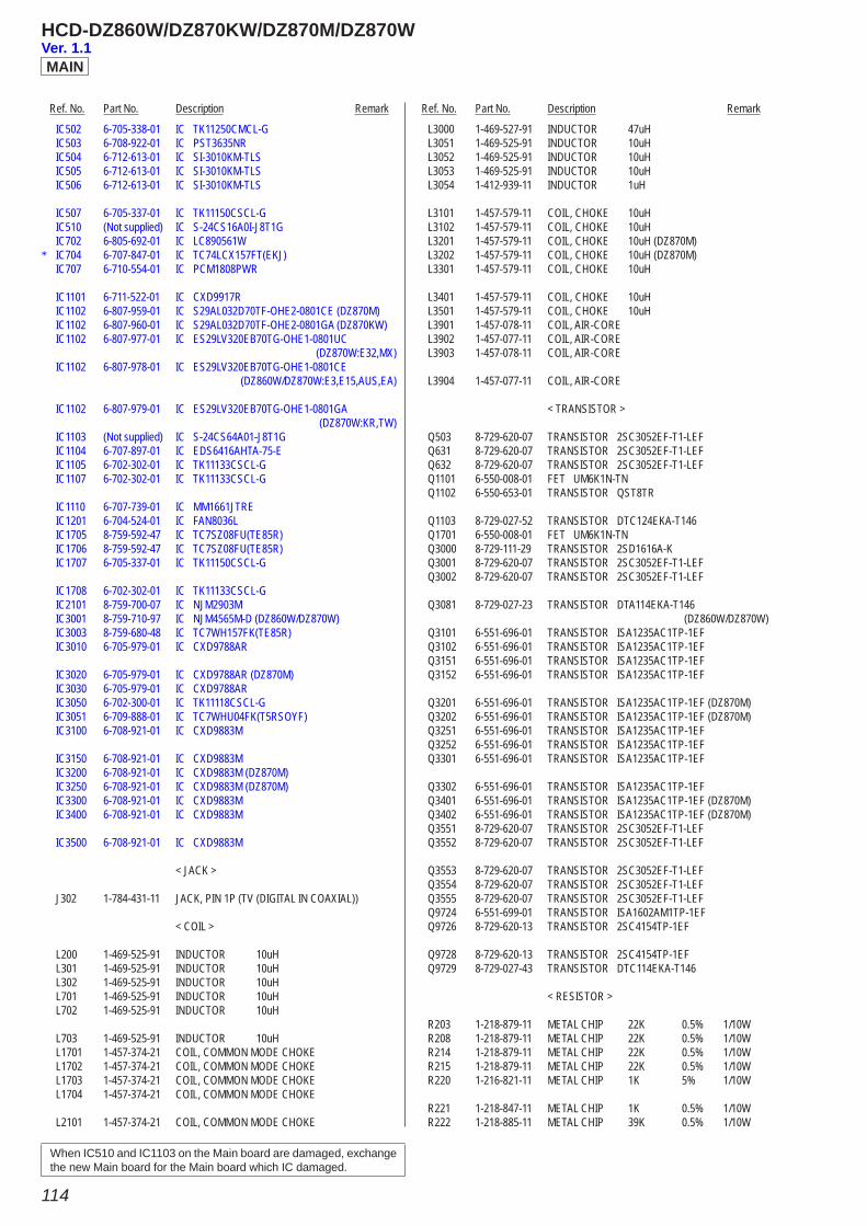
Ref. No. Part No. Description Remark Ref. No. Part No. Description Remark
HCD-DZ860W/DZ870KW/DZ870M/DZ870W
114
IC502 6-705-338-01 IC TK11250CMCL-G IC503 6-708-922-01 IC PST3635NR IC504 6-712-613-01 IC SI-3010KM-TLS IC505 6-712-613-01 IC SI-3010KM-TLS IC506 6-712-613-01 IC SI-3010KM-TLS
IC507 6-705-337-01 IC TK11150CSCL-G IC510 (Not supplied) IC S-24CS16A0I-J8T1G IC702 6-805-692-01 IC LC890561W* IC704 6-707-847-01 IC TC74LCX157FT(EKJ) IC707 6-710-554-01 IC PCM1808PWR
IC1101 6-711-522-01 IC CXD9917R IC1102 6-807-959-01 IC S29AL032D70TF-OHE2-0801CE (DZ870M) IC1102 6-807-960-01 IC S29AL032D70TF-OHE2-0801GA (DZ870KW) IC1102 6-807-977-01 IC ES29LV320EB70TG-OHE1-0801UC (DZ870W:E32,MX) IC1102 6-807-978-01 IC ES29LV320EB70TG-OHE1-0801CE (DZ860W/DZ870W:E3,E15,AUS,EA)
IC1102 6-807-979-01 IC ES29LV320EB70TG-OHE1-0801GA (DZ870W:KR,TW) IC1103 (Not supplied) IC S-24CS64A01-J8T1G IC1104 6-707-897-01 IC EDS6416AHTA-75-E IC1105 6-702-302-01 IC TK11133CSCL-G IC1107 6-702-302-01 IC TK11133CSCL-G
IC1110 6-707-739-01 IC MM1661JTRE IC1201 6-704-524-01 IC FAN8036L IC1705 8-759-592-47 IC TC7SZ08FU(TE85R) IC1706 8-759-592-47 IC TC7SZ08FU(TE85R) IC1707 6-705-337-01 IC TK11150CSCL-G
IC1708 6-702-302-01 IC TK11133CSCL-G IC2101 8-759-700-07 IC NJM2903M IC3001 8-759-710-97 IC NJM4565M-D (DZ860W/DZ870W) IC3003 8-759-680-48 IC TC7WH157FK(TE85R) IC3010 6-705-979-01 IC CXD9788AR
IC3020 6-705-979-01 IC CXD9788AR (DZ870M) IC3030 6-705-979-01 IC CXD9788AR IC3050 6-702-300-01 IC TK11118CSCL-G IC3051 6-709-888-01 IC TC7WHU04FK(T5RSOYF) IC3100 6-708-921-01 IC CXD9883M
IC3150 6-708-921-01 IC CXD9883M IC3200 6-708-921-01 IC CXD9883M (DZ870M) IC3250 6-708-921-01 IC CXD9883M (DZ870M) IC3300 6-708-921-01 IC CXD9883M IC3400 6-708-921-01 IC CXD9883M
IC3500 6-708-921-01 IC CXD9883M
< JACK >
J302 1-784-431-11 JACK, PIN 1P (TV (DIGITAL IN COAXIAL))
< COIL >
L200 1-469-525-91 INDUCTOR 10uH L301 1-469-525-91 INDUCTOR 10uH L302 1-469-525-91 INDUCTOR 10uH L701 1-469-525-91 INDUCTOR 10uH L702 1-469-525-91 INDUCTOR 10uH
L703 1-469-525-91 INDUCTOR 10uH L1701 1-457-374-21 COIL, COMMON MODE CHOKE L1702 1-457-374-21 COIL, COMMON MODE CHOKE L1703 1-457-374-21 COIL, COMMON MODE CHOKE L1704 1-457-374-21 COIL, COMMON MODE CHOKE
L2101 1-457-374-21 COIL, COMMON MODE CHOKE
L3000 1-469-527-91 INDUCTOR 47uH L3051 1-469-525-91 INDUCTOR 10uH L3052 1-469-525-91 INDUCTOR 10uH L3053 1-469-525-91 INDUCTOR 10uH L3054 1-412-939-11 INDUCTOR 1uH
L3101 1-457-579-11 COIL, CHOKE 10uH L3102 1-457-579-11 COIL, CHOKE 10uH L3201 1-457-579-11 COIL, CHOKE 10uH (DZ870M) L3202 1-457-579-11 COIL, CHOKE 10uH (DZ870M) L3301 1-457-579-11 COIL, CHOKE 10uH
L3401 1-457-579-11 COIL, CHOKE 10uH L3501 1-457-579-11 COIL, CHOKE 10uH L3901 1-457-078-11 COIL, AIR-CORE L3902 1-457-077-11 COIL, AIR-CORE L3903 1-457-078-11 COIL, AIR-CORE
L3904 1-457-077-11 COIL, AIR-CORE
< TRANSISTOR >
Q503 8-729-620-07 TRANSISTOR 2SC3052EF-T1-LEF Q631 8-729-620-07 TRANSISTOR 2SC3052EF-T1-LEF Q632 8-729-620-07 TRANSISTOR 2SC3052EF-T1-LEF Q1101 6-550-008-01 FET UM6K1N-TN Q1102 6-550-653-01 TRANSISTOR QST8TR
Q1103 8-729-027-52 TRANSISTOR DTC124EKA-T146 Q1701 6-550-008-01 FET UM6K1N-TN Q3000 8-729-111-29 TRANSISTOR 2SD1616A-K Q3001 8-729-620-07 TRANSISTOR 2SC3052EF-T1-LEF Q3002 8-729-620-07 TRANSISTOR 2SC3052EF-T1-LEF
Q3081 8-729-027-23 TRANSISTOR DTA114EKA-T146 (DZ860W/DZ870W) Q3101 6-551-696-01 TRANSISTOR ISA1235AC1TP-1EF Q3102 6-551-696-01 TRANSISTOR ISA1235AC1TP-1EF Q3151 6-551-696-01 TRANSISTOR ISA1235AC1TP-1EF Q3152 6-551-696-01 TRANSISTOR ISA1235AC1TP-1EF
Q3201 6-551-696-01 TRANSISTOR ISA1235AC1TP-1EF (DZ870M) Q3202 6-551-696-01 TRANSISTOR ISA1235AC1TP-1EF (DZ870M) Q3251 6-551-696-01 TRANSISTOR ISA1235AC1TP-1EF Q3252 6-551-696-01 TRANSISTOR ISA1235AC1TP-1EF Q3301 6-551-696-01 TRANSISTOR ISA1235AC1TP-1EF
Q3302 6-551-696-01 TRANSISTOR ISA1235AC1TP-1EF Q3401 6-551-696-01 TRANSISTOR ISA1235AC1TP-1EF (DZ870M) Q3402 6-551-696-01 TRANSISTOR ISA1235AC1TP-1EF (DZ870M) Q3551 8-729-620-07 TRANSISTOR 2SC3052EF-T1-LEF Q3552 8-729-620-07 TRANSISTOR 2SC3052EF-T1-LEF
Q3553 8-729-620-07 TRANSISTOR 2SC3052EF-T1-LEF Q3554 8-729-620-07 TRANSISTOR 2SC3052EF-T1-LEF Q3555 8-729-620-07 TRANSISTOR 2SC3052EF-T1-LEF Q9724 6-551-699-01 TRANSISTOR ISA1602AM1TP-1EF Q9726 8-729-620-13 TRANSISTOR 2SC4154TP-1EF
Q9728 8-729-620-13 TRANSISTOR 2SC4154TP-1EF Q9729 8-729-027-43 TRANSISTOR DTC114EKA-T146
< RESISTOR >
R203 1-218-879-11 METAL CHIP 22K 0.5% 1/10W R208 1-218-879-11 METAL CHIP 22K 0.5% 1/10W R214 1-218-879-11 METAL CHIP 22K 0.5% 1/10W R215 1-218-879-11 METAL CHIP 22K 0.5% 1/10W R220 1-216-821-11 METAL CHIP 1K 5% 1/10W
R221 1-218-847-11 METAL CHIP 1K 0.5% 1/10W R222 1-218-885-11 METAL CHIP 39K 0.5% 1/10W
MAIN
When IC510 and IC1103 on the Main board are damaged, exchange the new Main board for the Main board which IC damaged.
Ver. 1.1
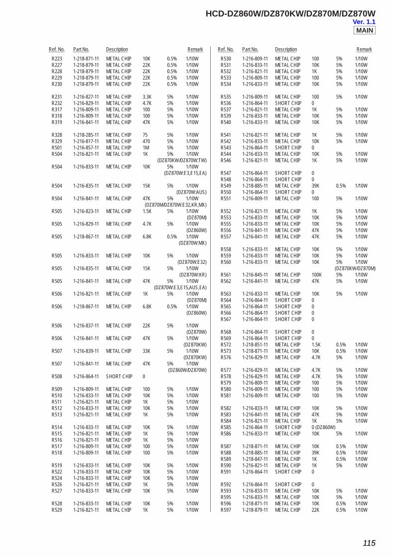
Ref. No. Part No. Description Remark Ref. No. Part No. Description Remark
HCD-DZ860W/DZ870KW/DZ870M/DZ870W
115115
R223 1-218-871-11 METAL CHIP 10K 0.5% 1/10W R227 1-218-879-11 METAL CHIP 22K 0.5% 1/10W R228 1-218-879-11 METAL CHIP 22K 0.5% 1/10W R229 1-218-879-11 METAL CHIP 22K 0.5% 1/10W R230 1-218-879-11 METAL CHIP 22K 0.5% 1/10W
R231 1-216-827-11 METAL CHIP 3.3K 5% 1/10W R232 1-216-829-11 METAL CHIP 4.7K 5% 1/10W R317 1-216-809-11 METAL CHIP 100 5% 1/10W R318 1-216-809-11 METAL CHIP 100 5% 1/10W R319 1-216-841-11 METAL CHIP 47K 5% 1/10W
R328 1-218-285-11 METAL CHIP 75 5% 1/10W R329 1-216-817-11 METAL CHIP 470 5% 1/10W R501 1-216-857-11 METAL CHIP 1M 5% 1/10W R504 1-216-821-11 METAL CHIP 1K 5% 1/10W (DZ870KW/DZ870W:TW) R504 1-216-833-11 METAL CHIP 10K 5% 1/10W (DZ870W:E3,E15,EA)
R504 1-216-835-11 METAL CHIP 15K 5% 1/10W (DZ870W:AUS) R504 1-216-841-11 METAL CHIP 47K 5% 1/10W (DZ870M/DZ870W:E32,KR,MX) R505 1-216-823-11 METAL CHIP 1.5K 5% 1/10W (DZ870M) R505 1-216-829-11 METAL CHIP 4.7K 5% 1/10W (DZ860W) R505 1-218-867-11 METAL CHIP 6.8K 0.5% 1/10W (DZ870W:MX)
R505 1-216-833-11 METAL CHIP 10K 5% 1/10W (DZ870W:E32) R505 1-216-835-11 METAL CHIP 15K 5% 1/10W (DZ870W:KR) R505 1-216-841-11 METAL CHIP 47K 5% 1/10W (DZ870W:E3,E15,AUS,EA) R506 1-216-821-11 METAL CHIP 1K 5% 1/10W (DZ870M) R506 1-218-867-11 METAL CHIP 6.8K 0.5% 1/10W (DZ860W)
R506 1-216-837-11 METAL CHIP 22K 5% 1/10W (DZ870W) R506 1-216-841-11 METAL CHIP 47K 5% 1/10W (DZ870KW) R507 1-216-839-11 METAL CHIP 33K 5% 1/10W (DZ870KW) R507 1-216-841-11 METAL CHIP 47K 5% 1/10W (DZ860W/DZ870W) R508 1-216-864-11 SHORT CHIP 0
R509 1-216-809-11 METAL CHIP 100 5% 1/10W R510 1-216-833-11 METAL CHIP 10K 5% 1/10W R511 1-216-821-11 METAL CHIP 1K 5% 1/10W R512 1-216-833-11 METAL CHIP 10K 5% 1/10W R513 1-216-821-11 METAL CHIP 1K 5% 1/10W
R514 1-216-833-11 METAL CHIP 10K 5% 1/10W R515 1-216-821-11 METAL CHIP 1K 5% 1/10W R516 1-216-821-11 METAL CHIP 1K 5% 1/10W R517 1-216-809-11 METAL CHIP 100 5% 1/10W R518 1-216-809-11 METAL CHIP 100 5% 1/10W
R519 1-216-833-11 METAL CHIP 10K 5% 1/10W R522 1-216-833-11 METAL CHIP 10K 5% 1/10W R524 1-216-833-11 METAL CHIP 10K 5% 1/10W R526 1-216-821-11 METAL CHIP 1K 5% 1/10W R527 1-216-833-11 METAL CHIP 10K 5% 1/10W
R528 1-216-833-11 METAL CHIP 10K 5% 1/10W R529 1-216-821-11 METAL CHIP 1K 5% 1/10W
R530 1-216-809-11 METAL CHIP 100 5% 1/10W R531 1-216-833-11 METAL CHIP 10K 5% 1/10W R532 1-216-821-11 METAL CHIP 1K 5% 1/10W R533 1-216-809-11 METAL CHIP 100 5% 1/10W R534 1-216-833-11 METAL CHIP 10K 5% 1/10W
R535 1-216-809-11 METAL CHIP 100 5% 1/10W R536 1-216-864-11 SHORT CHIP 0 R537 1-216-821-11 METAL CHIP 1K 5% 1/10W R539 1-216-833-11 METAL CHIP 10K 5% 1/10W R540 1-216-833-11 METAL CHIP 10K 5% 1/10W
R541 1-216-821-11 METAL CHIP 1K 5% 1/10W R542 1-216-833-11 METAL CHIP 10K 5% 1/10W R543 1-216-864-11 SHORT CHIP 0 R544 1-216-833-11 METAL CHIP 10K 5% 1/10W R546 1-216-821-11 METAL CHIP 1K 5% 1/10W
R547 1-216-864-11 SHORT CHIP 0 R548 1-216-864-11 SHORT CHIP 0 R549 1-218-885-11 METAL CHIP 39K 0.5% 1/10W R550 1-216-864-11 SHORT CHIP 0 R551 1-216-809-11 METAL CHIP 100 5% 1/10W
R552 1-216-821-11 METAL CHIP 1K 5% 1/10W R553 1-216-833-11 METAL CHIP 10K 5% 1/10W R555 1-216-833-11 METAL CHIP 10K 5% 1/10W R556 1-216-841-11 METAL CHIP 47K 5% 1/10W R557 1-216-841-11 METAL CHIP 47K 5% 1/10W
R558 1-216-833-11 METAL CHIP 10K 5% 1/10W R559 1-216-833-11 METAL CHIP 10K 5% 1/10W R560 1-216-833-11 METAL CHIP 10K 5% 1/10W (DZ870KW/DZ870M) R561 1-216-845-11 METAL CHIP 100K 5% 1/10W R562 1-216-841-11 METAL CHIP 47K 5% 1/10W
R563 1-216-833-11 METAL CHIP 10K 5% 1/10W R564 1-216-864-11 SHORT CHIP 0 R565 1-216-864-11 SHORT CHIP 0 R566 1-216-864-11 SHORT CHIP 0 R567 1-216-864-11 SHORT CHIP 0
R568 1-216-864-11 SHORT CHIP 0 R569 1-216-864-11 SHORT CHIP 0 R572 1-218-851-11 METAL CHIP 1.5K 0.5% 1/10W R573 1-218-871-11 METAL CHIP 10K 0.5% 1/10W R576 1-216-829-11 METAL CHIP 4.7K 5% 1/10W
R577 1-216-829-11 METAL CHIP 4.7K 5% 1/10W R578 1-216-829-11 METAL CHIP 4.7K 5% 1/10W R579 1-216-809-11 METAL CHIP 100 5% 1/10W R580 1-216-809-11 METAL CHIP 100 5% 1/10W R581 1-216-809-11 METAL CHIP 100 5% 1/10W
R582 1-216-833-11 METAL CHIP 10K 5% 1/10W R583 1-216-841-11 METAL CHIP 47K 5% 1/10W R584 1-216-821-11 METAL CHIP 1K 5% 1/10W R585 1-216-864-11 SHORT CHIP 0 (DZ860W) R586 1-216-833-11 METAL CHIP 10K 5% 1/10W
R587 1-218-871-11 METAL CHIP 10K 0.5% 1/10W R588 1-218-885-11 METAL CHIP 39K 0.5% 1/10W R589 1-218-847-11 METAL CHIP 1K 0.5% 1/10W R590 1-216-821-11 METAL CHIP 1K 5% 1/10W R591 1-216-864-11 SHORT CHIP 0
R592 1-216-864-11 SHORT CHIP 0 R593 1-216-833-11 METAL CHIP 10K 5% 1/10W R595 1-216-833-11 METAL CHIP 10K 5% 1/10W R596 1-218-871-11 METAL CHIP 10K 0.5% 1/10W R597 1-218-879-11 METAL CHIP 22K 0.5% 1/10W
MAINVer. 1.1
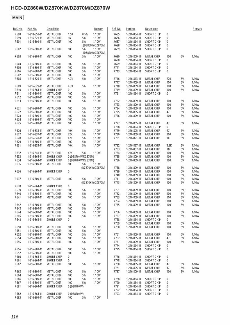
Ref. No. Part No. Description Remark Ref. No. Part No. Description Remark
HCD-DZ860W/DZ870KW/DZ870M/DZ870W
116
R598 1-218-851-11 METAL CHIP 1.5K 0.5% 1/10W R599 1-216-821-11 METAL CHIP 1K 5% 1/10W R601 1-216-809-11 METAL CHIP 100 5% 1/10W (DZ860W/DZ870M) R602 1-216-809-11 METAL CHIP 100 5% 1/10W (DZ860W/DZ870M) R603 1-216-809-11 METAL CHIP 100 5% 1/10W
R604 1-216-809-11 METAL CHIP 100 5% 1/10W R605 1-216-809-11 METAL CHIP 100 5% 1/10W R606 1-216-809-11 METAL CHIP 100 5% 1/10W R607 1-216-809-11 METAL CHIP 100 5% 1/10W R608 1-216-829-11 METAL CHIP 4.7K 5% 1/10W
R609 1-216-829-11 METAL CHIP 4.7K 5% 1/10W R610 1-216-864-11 SHORT CHIP 0 R611 1-216-809-11 METAL CHIP 100 5% 1/10W R612 1-216-809-11 METAL CHIP 100 5% 1/10W R613 1-216-809-11 METAL CHIP 100 5% 1/10W
R621 1-216-809-11 METAL CHIP 100 5% 1/10W R622 1-216-809-11 METAL CHIP 100 5% 1/10W R623 1-216-809-11 METAL CHIP 100 5% 1/10W R624 1-216-809-11 METAL CHIP 100 5% 1/10W R625 1-216-809-11 METAL CHIP 100 5% 1/10W
R626 1-216-833-11 METAL CHIP 10K 5% 1/10W R627 1-216-837-11 METAL CHIP 22K 5% 1/10W R628 1-216-841-11 METAL CHIP 47K 5% 1/10W R629 1-216-809-11 METAL CHIP 100 5% 1/10W R631 1-216-833-11 METAL CHIP 10K 5% 1/10W
R632 1-216-841-11 METAL CHIP 47K 5% 1/10W R633 1-216-864-11 SHORT CHIP 0 (DZ870KW/DZ870M) R634 1-216-864-11 SHORT CHIP 0 (DZ870KW/DZ870M) R635 1-216-809-11 METAL CHIP 100 5% 1/10W (DZ870KW/DZ870M) R636 1-216-864-11 SHORT CHIP 0
R637 1-216-809-11 METAL CHIP 100 5% 1/10W (DZ870KW/DZ870M) R638 1-216-864-11 SHORT CHIP 0 R639 1-216-809-11 METAL CHIP 100 5% 1/10W R640 1-216-809-11 METAL CHIP 100 5% 1/10W R641 1-216-809-11 METAL CHIP 100 5% 1/10W
R642 1-216-809-11 METAL CHIP 100 5% 1/10W R643 1-216-809-11 METAL CHIP 100 5% 1/10W R644 1-216-809-11 METAL CHIP 100 5% 1/10W R645 1-216-809-11 METAL CHIP 100 5% 1/10W R648 1-216-864-11 SHORT CHIP 0
R650 1-216-809-11 METAL CHIP 100 5% 1/10W R651 1-216-809-11 METAL CHIP 100 5% 1/10W R652 1-216-809-11 METAL CHIP 100 5% 1/10W R654 1-216-809-11 METAL CHIP 100 5% 1/10W R655 1-216-809-11 METAL CHIP 100 5% 1/10W
R656 1-216-809-11 METAL CHIP 100 5% 1/10W R657 1-216-809-11 METAL CHIP 100 5% 1/10W R660 1-216-864-11 SHORT CHIP 0 R661 1-216-864-11 SHORT CHIP 0 R662 1-216-809-11 METAL CHIP 100 5% 1/10W
R663 1-216-809-11 METAL CHIP 100 5% 1/10W R664 1-216-809-11 METAL CHIP 100 5% 1/10W R666 1-216-809-11 METAL CHIP 100 5% 1/10W R667 1-216-809-11 METAL CHIP 100 5% 1/10W R681 1-216-864-11 SHORT CHIP 0 (DZ870KW)
R682 1-216-864-11 SHORT CHIP 0 (DZ870KW) R683 1-216-809-11 METAL CHIP 100 5% 1/10W
R685 1-216-864-11 SHORT CHIP 0 R686 1-216-864-11 SHORT CHIP 0 R687 1-216-864-11 SHORT CHIP 0 R688 1-216-864-11 SHORT CHIP 0 R689 1-216-864-11 SHORT CHIP 0
R690 1-216-809-11 METAL CHIP 100 5% 1/10W R698 1-216-864-11 SHORT CHIP 0 R699 1-216-864-11 SHORT CHIP 0 R711 1-216-864-11 SHORT CHIP 0 R713 1-216-864-11 SHORT CHIP 0
R716 1-216-813-11 METAL CHIP 220 5% 1/10W R717 1-216-809-11 METAL CHIP 100 5% 1/10W R718 1-216-809-11 METAL CHIP 100 5% 1/10W R719 1-216-809-11 METAL CHIP 100 5% 1/10W R721 1-216-864-11 SHORT CHIP 0
R722 1-216-809-11 METAL CHIP 100 5% 1/10W R723 1-216-809-11 METAL CHIP 100 5% 1/10W R724 1-216-809-11 METAL CHIP 100 5% 1/10W R725 1-216-805-11 METAL CHIP 47 5% 1/10W R726 1-216-809-11 METAL CHIP 100 5% 1/10W
R727 1-216-805-11 METAL CHIP 47 5% 1/10W R728 1-216-864-11 SHORT CHIP 0 R729 1-216-805-11 METAL CHIP 47 5% 1/10W R730 1-216-809-11 METAL CHIP 100 5% 1/10W R731 1-216-821-11 METAL CHIP 1K 5% 1/10W
R732 1-216-827-11 METAL CHIP 3.3K 5% 1/10W R733 1-216-857-11 METAL CHIP 1M 5% 1/10W R734 1-216-809-11 METAL CHIP 100 5% 1/10W R735 1-216-809-11 METAL CHIP 100 5% 1/10W R736 1-216-809-11 METAL CHIP 100 5% 1/10W
R738 1-216-809-11 METAL CHIP 100 5% 1/10W R739 1-216-809-11 METAL CHIP 100 5% 1/10W R740 1-216-809-11 METAL CHIP 100 5% 1/10W R741 1-216-809-11 METAL CHIP 100 5% 1/10W R743 1-216-809-11 METAL CHIP 100 5% 1/10W
R751 1-216-809-11 METAL CHIP 100 5% 1/10W R752 1-216-809-11 METAL CHIP 100 5% 1/10W R753 1-216-809-11 METAL CHIP 100 5% 1/10W R754 1-216-809-11 METAL CHIP 100 5% 1/10W R755 1-216-809-11 METAL CHIP 100 5% 1/10W
R756 1-216-809-11 METAL CHIP 100 5% 1/10W R757 1-216-809-11 METAL CHIP 100 5% 1/10W R758 1-216-864-11 SHORT CHIP 0 R759 1-216-809-11 METAL CHIP 100 5% 1/10W R760 1-216-809-11 METAL CHIP 100 5% 1/10W
R761 1-216-809-11 METAL CHIP 100 5% 1/10W R762 1-216-805-11 METAL CHIP 47 5% 1/10W R771 1-216-809-11 METAL CHIP 100 5% 1/10W R774 1-216-864-11 SHORT CHIP 0 R775 1-216-864-11 SHORT CHIP 0
R776 1-216-864-11 SHORT CHIP 0 R778 1-216-864-11 SHORT CHIP 0 R780 1-216-805-11 METAL CHIP 47 5% 1/10W R781 1-216-805-11 METAL CHIP 47 5% 1/10W R787 1-216-809-11 METAL CHIP 100 5% 1/10W
R788 1-216-864-11 SHORT CHIP 0 R790 1-216-864-11 SHORT CHIP 0 R791 1-216-864-11 SHORT CHIP 0 R792 1-216-864-11 SHORT CHIP 0 R793 1-216-864-11 SHORT CHIP 0
MAIN
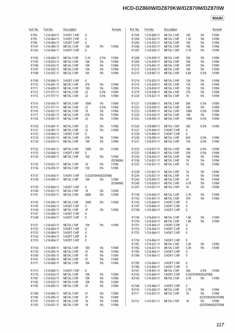
Ref. No. Part No. Description Remark Ref. No. Part No. Description Remark
HCD-DZ860W/DZ870KW/DZ870M/DZ870W
117117
R794 1-216-864-11 SHORT CHIP 0 R795 1-216-864-11 SHORT CHIP 0 R798 1-216-864-11 SHORT CHIP 0 R1101 1-216-809-11 METAL CHIP 100 5% 1/10W R1102 1-216-864-11 SHORT CHIP 0
R1103 1-218-864-11 METAL CHIP 5.1K 0.5% 1/10W R1105 1-216-833-11 METAL CHIP 10K 5% 1/10W R1106 1-216-833-11 METAL CHIP 10K 5% 1/10W R1107 1-216-833-11 METAL CHIP 10K 5% 1/10W R1108 1-216-857-11 METAL CHIP 1M 5% 1/10W
R1109 1-216-864-11 SHORT CHIP 0 R1110 1-216-841-11 METAL CHIP 47K 5% 1/10W R1111 1-216-809-11 METAL CHIP 100 5% 1/10W R1112 1-211-977-11 METAL CHIP 22 0.5% 1/10W R1113 1-211-977-11 METAL CHIP 22 0.5% 1/10W
R1114 1-216-845-11 METAL CHIP 100K 5% 1/10W R1115 1-211-977-11 METAL CHIP 22 0.5% 1/10W R1116 1-216-821-11 METAL CHIP 1K 5% 1/10W R1117 1-216-841-11 METAL CHIP 47K 5% 1/10W R1118 1-216-801-11 METAL CHIP 22 5% 1/10W
R1120 1-216-801-11 METAL CHIP 22 5% 1/10W R1121 1-216-801-11 METAL CHIP 22 5% 1/10W R1123 1-216-864-11 SHORT CHIP 0 R1124 1-216-841-11 METAL CHIP 47K 5% 1/10W R1126 1-216-833-11 METAL CHIP 10K 5% 1/10W
R1132 1-216-845-11 METAL CHIP 100K 5% 1/10W R1133 1-216-864-11 SHORT CHIP 0 R1134 1-216-809-11 METAL CHIP 100 5% 1/10W (DZ860W) R1135 1-216-821-11 METAL CHIP 1K 5% 1/10W R1136 1-216-835-11 METAL CHIP 15K 5% 1/10W
R1137 1-216-864-11 SHORT CHIP 0 (DZ870KW/DZ870M) R1138 1-216-809-11 METAL CHIP 100 5% 1/10W (DZ860W) R1139 1-216-864-11 SHORT CHIP 0 R1140 1-216-821-11 METAL CHIP 1K 5% 1/10W R1141 1-216-855-11 METAL CHIP 680K 5% 1/10W
R1142 1-216-845-11 METAL CHIP 100K 5% 1/10W R1145 1-216-864-11 SHORT CHIP 0 R1146 1-216-805-11 METAL CHIP 47 5% 1/10W R1147 1-216-864-11 SHORT CHIP 0 R1148 1-216-864-11 SHORT CHIP 0
R1151 1-216-833-11 METAL CHIP 10K 5% 1/10W R1152 1-216-864-11 SHORT CHIP 0 R1153 1-216-864-11 SHORT CHIP 0 R1154 1-216-864-11 SHORT CHIP 0 R1155 1-216-864-11 SHORT CHIP 0
R1156 1-216-809-11 METAL CHIP 100 5% 1/10W R1159 1-216-805-11 METAL CHIP 47 5% 1/10W R1160 1-216-805-11 METAL CHIP 47 5% 1/10W R1161 1-216-805-11 METAL CHIP 47 5% 1/10W R1171 1-216-809-11 METAL CHIP 100 5% 1/10W
R1175 1-216-864-11 SHORT CHIP 0 R1176 1-216-833-11 METAL CHIP 10K 5% 1/10W R1181 1-216-833-11 METAL CHIP 10K 5% 1/10W R1182 1-216-833-11 METAL CHIP 10K 5% 1/10W R1183 1-216-805-11 METAL CHIP 47 5% 1/10W
R1184 1-216-805-11 METAL CHIP 47 5% 1/10W R1185 1-216-805-11 METAL CHIP 47 5% 1/10W R1191 1-216-821-11 METAL CHIP 1K 5% 1/10W R1193 1-216-821-11 METAL CHIP 1K 5% 1/10W
R1198 1-216-809-11 METAL CHIP 100 5% 1/10W R1204 1-216-822-11 METAL CHIP 1.2K 5% 1/10W R1205 1-216-833-11 METAL CHIP 10K 5% 1/10W R1206 1-216-833-11 METAL CHIP 10K 5% 1/10W R1207 1-216-826-11 METAL CHIP 2.7K 5% 1/10W
R1208 1-216-839-11 METAL CHIP 33K 5% 1/10W R1209 1-216-839-11 METAL CHIP 33K 5% 1/10W R1210 1-216-841-11 METAL CHIP 47K 5% 1/10W R1212 1-216-833-11 METAL CHIP 10K 5% 1/10W R1213 1-218-867-11 METAL CHIP 6.8K 0.5% 1/10W
R1214 1-216-835-11 METAL CHIP 15K 5% 1/10W R1215 1-216-834-11 METAL CHIP 12K 5% 1/10W R1216 1-216-834-11 METAL CHIP 12K 5% 1/10W R1219 1-216-838-11 METAL CHIP 27K 5% 1/10W R1220 1-216-821-11 METAL CHIP 1K 5% 1/10W
R1221 1-218-889-11 METAL CHIP 56K 0.5% 1/10W R1222 1-216-839-11 METAL CHIP 33K 5% 1/10W R1223 1-218-895-11 METAL CHIP 100K 0.5% 1/10W R1224 1-216-833-11 METAL CHIP 10K 5% 1/10W R1225 1-218-895-11 METAL CHIP 100K 0.5% 1/10W
R1226 1-218-889-11 METAL CHIP 56K 0.5% 1/10W R1227 1-216-864-11 SHORT CHIP 0 R1228 1-216-864-11 SHORT CHIP 0 R1230 1-218-893-11 METAL CHIP 82K 0.5% 1/10W R1231 1-218-875-11 METAL CHIP 15K 0.5% 1/10W
R1232 1-218-877-11 METAL CHIP 18K 0.5% 1/10W R1233 1-218-883-11 METAL CHIP 33K 0.5% 1/10W R1234 1-216-833-11 METAL CHIP 10K 5% 1/10W R1236 1-216-821-11 METAL CHIP 1K 5% 1/10W R1237 1-216-821-11 METAL CHIP 1K 5% 1/10W
R1238 1-216-821-11 METAL CHIP 1K 5% 1/10W R1239 1-216-821-11 METAL CHIP 1K 5% 1/10W R1243 1-216-805-11 METAL CHIP 47 5% 1/10W R1246 1-216-829-11 METAL CHIP 4.7K 5% 1/10W R1247 1-216-821-11 METAL CHIP 1K 5% 1/10W
R1730 1-216-826-11 METAL CHIP 2.7K 5% 1/10W R1742 1-216-841-11 METAL CHIP 47K 5% 1/10W R1743 1-216-864-11 SHORT CHIP 0 R1747 1-216-864-11 SHORT CHIP 0 R1748 1-216-864-11 SHORT CHIP 0
R1749 1-216-824-11 METAL CHIP 1.8K 5% 1/10W R1750 1-216-824-11 METAL CHIP 1.8K 5% 1/10W R1751 1-216-864-11 SHORT CHIP 0 R1752 1-216-864-11 SHORT CHIP 0 R1753 1-216-864-11 SHORT CHIP 0
R1754 1-216-864-11 SHORT CHIP 0 R1781 1-216-827-11 METAL CHIP 3.3K 5% 1/10W R1782 1-216-827-11 METAL CHIP 3.3K 5% 1/10W R1783 1-216-864-11 SHORT CHIP 0 R1784 1-216-864-11 SHORT CHIP 0
R1785 1-216-864-11 SHORT CHIP 0 R1786 1-216-864-11 SHORT CHIP 0 R2101 1-218-841-11 METAL CHIP 560 0.5% 1/10W R2103 1-216-864-11 SHORT CHIP 0 (DZ870KW/DZ870M) R2104 1-216-829-11 METAL CHIP 4.7K 5% 1/10W
R2108 1-216-864-11 SHORT CHIP 0 R2110 1-216-826-11 METAL CHIP 2.7K 5% 1/10W R2111 1-216-821-11 METAL CHIP 1K 5% 1/10W (DZ870KW/DZ870M) R2112 1-216-821-11 METAL CHIP 1K 5% 1/10W (DZ870KW/DZ870M)
MAIN

Ref. No. Part No. Description Remark Ref. No. Part No. Description Remark
HCD-DZ860W/DZ870KW/DZ870M/DZ870W
118
R2114 1-216-801-11 METAL CHIP 22 5% 1/10W R2115 1-216-864-11 SHORT CHIP 0 R2116 1-216-864-11 SHORT CHIP 0 (DZ870KW/DZ870M) R2117 1-216-833-11 METAL CHIP 10K 5% 1/10W (DZ860W/DZ870W) R2119 1-216-864-11 SHORT CHIP 0
R2121 1-216-864-11 SHORT CHIP 0 R2123 1-216-864-11 SHORT CHIP 0 R2127 1-216-833-11 METAL CHIP 10K 5% 1/10W R2128 1-216-833-11 METAL CHIP 10K 5% 1/10W R2129 1-216-845-11 METAL CHIP 100K 5% 1/10W
R2133 1-216-864-11 SHORT CHIP 0 R2134 1-216-864-11 SHORT CHIP 0 R2135 1-216-805-11 METAL CHIP 47 5% 1/10W (DZ870KW/DZ870M) R2137 1-216-833-11 METAL CHIP 10K 5% 1/10W (DZ870KW/DZ870M) R2138 1-216-833-11 METAL CHIP 10K 5% 1/10W (DZ870KW/DZ870M)
R2150 1-216-827-11 METAL CHIP 3.3K 5% 1/10W R2151 1-216-827-11 METAL CHIP 3.3K 5% 1/10W R2152 1-216-827-11 METAL CHIP 3.3K 5% 1/10W R2154 1-216-833-11 METAL CHIP 10K 5% 1/10W (DZ860W/DZ870W) R2155 1-216-833-11 METAL CHIP 10K 5% 1/10W
R2156 1-216-833-11 METAL CHIP 10K 5% 1/10W R2157 1-216-833-11 METAL CHIP 10K 5% 1/10W R2158 1-216-833-11 METAL CHIP 10K 5% 1/10W R2159 1-216-833-11 METAL CHIP 10K 5% 1/10W R2160 1-216-833-11 METAL CHIP 10K 5% 1/10W
R2167 1-216-864-11 SHORT CHIP 0 R2168 1-216-815-11 METAL CHIP 330 5% 1/10W R2176 1-216-864-11 SHORT CHIP 0 R2177 1-216-864-11 SHORT CHIP 0 R2178 1-216-821-11 METAL CHIP 1K 5% 1/10W
R2179 1-216-809-11 METAL CHIP 100 5% 1/10W R2180 1-216-833-11 METAL CHIP 10K 5% 1/10W R2181 1-216-833-11 METAL CHIP 10K 5% 1/10W R2182 1-216-864-11 SHORT CHIP 0 R2184 1-216-809-11 METAL CHIP 100 5% 1/10W
R2185 1-216-809-11 METAL CHIP 100 5% 1/10W R2187 1-216-805-11 METAL CHIP 47 5% 1/10W R2188 1-216-864-11 SHORT CHIP 0 R2189 1-216-833-11 METAL CHIP 10K 5% 1/10W R2191 1-245-287-11 METAL CHIP 0.1 1% 1W
R2192 1-218-835-11 METAL CHIP 330 0.5% 1/10W R2193 1-218-883-11 METAL CHIP 33K 0.5% 1/10W R2194 1-218-883-11 METAL CHIP 33K 0.5% 1/10W R2195 1-216-809-11 METAL CHIP 100 5% 1/10W R2201 1-216-864-11 SHORT CHIP 0
R2203 1-216-864-11 SHORT CHIP 0 R2746 1-216-864-11 SHORT CHIP 0 R3001 1-216-833-11 METAL CHIP 10K 5% 1/10W R3002 1-216-833-11 METAL CHIP 10K 5% 1/10W R3003 1-216-821-11 METAL CHIP 1K 5% 1/10W
R3004 1-216-825-11 METAL CHIP 2.2K 5% 1/10W R3011 1-216-817-11 METAL CHIP 470 5% 1/10W R3012 1-216-817-11 METAL CHIP 470 5% 1/10W R3013 1-216-833-11 METAL CHIP 10K 5% 1/10W R3014 1-216-805-11 METAL CHIP 47 5% 1/10W
R3015 1-216-805-11 METAL CHIP 47 5% 1/10W
R3017 1-216-809-11 METAL CHIP 100 5% 1/10W R3021 1-216-817-11 METAL CHIP 470 5% 1/10W (DZ870M) R3022 1-216-817-11 METAL CHIP 470 5% 1/10W (DZ870M) R3023 1-216-805-11 METAL CHIP 47 5% 1/10W (DZ870M) R3024 1-216-805-11 METAL CHIP 47 5% 1/10W (DZ870M)
R3026 1-216-809-11 METAL CHIP 100 5% 1/10W (DZ870M) R3031 1-216-817-11 METAL CHIP 470 5% 1/10W R3032 1-216-817-11 METAL CHIP 470 5% 1/10W R3033 1-216-833-11 METAL CHIP 10K 5% 1/10W R3034 1-216-805-11 METAL CHIP 47 5% 1/10W
R3035 1-216-805-11 METAL CHIP 47 5% 1/10W R3037 1-216-809-11 METAL CHIP 100 5% 1/10W R3040 1-216-864-11 SHORT CHIP 0 R3041 1-216-864-11 SHORT CHIP 0 R3042 1-216-864-11 SHORT CHIP 0
R3043 1-216-864-11 SHORT CHIP 0 R3044 1-216-864-11 SHORT CHIP 0 R3047 1-216-833-11 METAL CHIP 10K 5% 1/10W R3049 1-216-864-11 SHORT CHIP 0 R3050 1-216-864-11 SHORT CHIP 0
R3051 1-216-097-11 RES-CHIP 100K 5% 1/10W R3052 1-216-857-11 METAL CHIP 1M 5% 1/10W R3053 1-216-817-11 METAL CHIP 470 5% 1/10W R3054 1-216-809-11 METAL CHIP 100 5% 1/10W R3055 1-216-805-11 METAL CHIP 47 5% 1/10W
R3056 1-216-864-11 SHORT CHIP 0 (DZ860W/DZ870KW/DZ870W) R3057 1-216-805-11 METAL CHIP 47 5% 1/10W (DZ870M) R3057 1-216-864-11 SHORT CHIP 0 (DZ860W/DZ870KW/DZ870W) R3058 1-216-864-11 SHORT CHIP 0 R3059 1-216-833-11 METAL CHIP 10K 5% 1/10W
R3060 1-216-833-11 METAL CHIP 10K 5% 1/10W R3061 1-216-864-11 SHORT CHIP 0 R3063 1-216-821-11 METAL CHIP 1K 5% 1/10W R3064 1-216-821-11 METAL CHIP 1K 5% 1/10W R3065 1-216-809-11 METAL CHIP 100 5% 1/10W
R3066 1-216-809-11 METAL CHIP 100 5% 1/10W R3067 1-216-809-11 METAL CHIP 100 5% 1/10W R3068 1-216-809-11 METAL CHIP 100 5% 1/10W R3069 1-216-809-11 METAL CHIP 100 5% 1/10W R3070 1-216-809-11 METAL CHIP 100 5% 1/10W
R3071 1-216-809-11 METAL CHIP 100 5% 1/10W R3072 1-216-809-11 METAL CHIP 100 5% 1/10W R3073 1-216-809-11 METAL CHIP 100 5% 1/10W R3074 1-216-805-11 METAL CHIP 47 5% 1/10W R3075 1-216-805-11 METAL CHIP 47 5% 1/10W
R3076 1-216-805-11 METAL CHIP 47 5% 1/10W R3077 1-216-809-11 METAL CHIP 100 5% 1/10W R3078 1-216-809-11 METAL CHIP 100 5% 1/10W R3079 1-216-809-11 METAL CHIP 100 5% 1/10W R3085 1-216-839-11 METAL CHIP 33K 5% 1/10W (DZ860W/DZ870W)
R3086 1-216-839-11 METAL CHIP 33K 5% 1/10W (DZ860W/DZ870W) R3087 1-216-833-11 METAL CHIP 10K 5% 1/10W (DZ860W/DZ870W)
MAIN
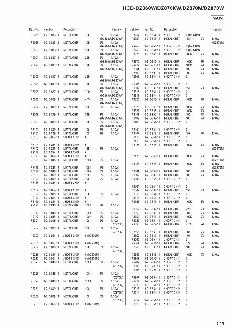
Ref. No. Part No. Description Remark Ref. No. Part No. Description Remark
HCD-DZ860W/DZ870KW/DZ870M/DZ870W
119119
R3088 1-216-833-11 METAL CHIP 10K 5% 1/10W (DZ860W/DZ870W) R3089 1-216-833-11 METAL CHIP 10K 5% 1/10W (DZ860W/DZ870W) R3090 1-216-833-11 METAL CHIP 10K 5% 1/10W (DZ860W/DZ870W) R3091 1-216-837-11 METAL CHIP 22K 5% 1/10W (DZ860W/DZ870W) R3092 1-216-837-11 METAL CHIP 22K 5% 1/10W (DZ860W/DZ870W)
R3093 1-216-837-11 METAL CHIP 22K 5% 1/10W (DZ860W/DZ870W) R3094 1-216-837-11 METAL CHIP 22K 5% 1/10W (DZ860W/DZ870W) R3095 1-216-827-11 METAL CHIP 3.3K 5% 1/10W (DZ860W/DZ870W) R3096 1-216-829-11 METAL CHIP 4.7K 5% 1/10W (DZ860W/DZ870W) R3097 1-216-809-11 METAL CHIP 100 5% 1/10W
R3098 1-216-839-11 METAL CHIP 33K 5% 1/10W (DZ860W/DZ870W) R3099 1-216-839-11 METAL CHIP 33K 5% 1/10W (DZ860W/DZ870W) R3101 1-216-809-11 METAL CHIP 100 5% 1/10W R3102 1-216-809-11 METAL CHIP 100 5% 1/10W R3103 1-216-864-11 SHORT CHIP 0
R3104 1-216-864-11 SHORT CHIP 0 R3107 1-216-835-11 METAL CHIP 15K 5% 1/10W R3115 1-216-864-11 SHORT CHIP 0 R3116 1-216-864-11 SHORT CHIP 0 R3125 1-216-845-11 METAL CHIP 100K 5% 1/10W
R3126 1-216-845-11 METAL CHIP 100K 5% 1/10W R3127 1-216-845-11 METAL CHIP 100K 5% 1/10W R3151 1-216-809-11 METAL CHIP 100 5% 1/10W R3152 1-216-809-11 METAL CHIP 100 5% 1/10W R3153 1-216-864-11 SHORT CHIP 0
R3154 1-216-864-11 SHORT CHIP 0 R3157 1-216-835-11 METAL CHIP 15K 5% 1/10W R3165 1-216-864-11 SHORT CHIP 0 R3166 1-216-864-11 SHORT CHIP 0 R3175 1-216-845-11 METAL CHIP 100K 5% 1/10W
R3176 1-216-845-11 METAL CHIP 100K 5% 1/10W R3177 1-216-845-11 METAL CHIP 100K 5% 1/10W R3201 1-216-809-11 METAL CHIP 100 5% 1/10W (DZ870M) R3202 1-216-809-11 METAL CHIP 100 5% 1/10W (DZ870M) R3203 1-216-864-11 SHORT CHIP 0 (DZ870M)
R3204 1-216-864-11 SHORT CHIP 0 (DZ870M) R3207 1-216-835-11 METAL CHIP 15K 5% 1/10W (DZ870M) R3215 1-216-864-11 SHORT CHIP 0 (DZ870M) R3216 1-216-864-11 SHORT CHIP 0 (DZ870M) R3225 1-216-845-11 METAL CHIP 100K 5% 1/10W (DZ870M)
R3226 1-216-845-11 METAL CHIP 100K 5% 1/10W (DZ870M) R3227 1-216-845-11 METAL CHIP 100K 5% 1/10W (DZ870M) R3251 1-216-809-11 METAL CHIP 100 5% 1/10W (DZ870M) R3252 1-216-809-11 METAL CHIP 100 5% 1/10W (DZ870M) R3253 1-216-864-11 SHORT CHIP 0 (DZ870M)
R3254 1-216-864-11 SHORT CHIP 0 (DZ870M) R3257 1-216-835-11 METAL CHIP 15K 5% 1/10W (DZ870M) R3265 1-216-864-11 SHORT CHIP 0 (DZ870M) R3266 1-216-864-11 SHORT CHIP 0 (DZ870M) R3275 1-216-845-11 METAL CHIP 100K 5% 1/10W
R3276 1-216-845-11 METAL CHIP 100K 5% 1/10W R3277 1-216-845-11 METAL CHIP 100K 5% 1/10W R3301 1-216-809-11 METAL CHIP 100 5% 1/10W R3302 1-216-809-11 METAL CHIP 100 5% 1/10W R3303 1-216-864-11 SHORT CHIP 0
R3304 1-216-864-11 SHORT CHIP 0 R3307 1-216-835-11 METAL CHIP 15K 5% 1/10W R3315 1-216-864-11 SHORT CHIP 0 R3316 1-216-864-11 SHORT CHIP 0 R3325 1-216-845-11 METAL CHIP 100K 5% 1/10W
R3326 1-216-845-11 METAL CHIP 100K 5% 1/10W R3327 1-216-845-11 METAL CHIP 100K 5% 1/10W R3401 1-216-809-11 METAL CHIP 100 5% 1/10W R3402 1-216-809-11 METAL CHIP 100 5% 1/10W R3403 1-216-864-11 SHORT CHIP 0
R3404 1-216-864-11 SHORT CHIP 0 R3407 1-216-835-11 METAL CHIP 15K 5% 1/10W R3415 1-216-864-11 SHORT CHIP 0 R3416 1-216-864-11 SHORT CHIP 0 R3425 1-216-845-11 METAL CHIP 100K 5% 1/10W (DZ870M)
R3426 1-216-845-11 METAL CHIP 100K 5% 1/10W (DZ870M) R3427 1-216-845-11 METAL CHIP 100K 5% 1/10W (DZ870M) R3501 1-216-809-11 METAL CHIP 100 5% 1/10W R3502 1-216-809-11 METAL CHIP 100 5% 1/10W R3503 1-216-864-11 SHORT CHIP 0
R3504 1-216-864-11 SHORT CHIP 0 R3507 1-216-835-11 METAL CHIP 15K 5% 1/10W R3515 1-216-864-11 SHORT CHIP 0 R3516 1-216-864-11 SHORT CHIP 0 R3551 1-216-845-11 METAL CHIP 100K 5% 1/10W
R3552 1-216-837-11 METAL CHIP 22K 5% 1/10W R3553 1-216-833-11 METAL CHIP 10K 5% 1/10W R3554 1-216-845-11 METAL CHIP 100K 5% 1/10W R3555 1-216-864-11 SHORT CHIP 0 R3556 1-216-829-11 METAL CHIP 4.7K 5% 1/10W
R3558 1-216-833-11 METAL CHIP 10K 5% 1/10W R3559 1-216-833-11 METAL CHIP 10K 5% 1/10W R3560 1-216-864-11 SHORT CHIP 0 R3561 1-216-841-11 METAL CHIP 47K 5% 1/10W R3562 1-216-833-11 METAL CHIP 10K 5% 1/10W
R3563 1-216-845-11 METAL CHIP 100K 5% 1/10W R3901 1-216-296-11 SHORT CHIP 0 R3902 1-216-296-11 SHORT CHIP 0 R3905 1-216-296-11 SHORT CHIP 0 R3906 1-216-296-11 SHORT CHIP 0
R3907 1-216-864-11 SHORT CHIP 0 R3911 1-216-864-11 SHORT CHIP 0 R3912 1-216-864-11 SHORT CHIP 0 R3913 1-216-864-11 SHORT CHIP 0 R3914 1-216-864-11 SHORT CHIP 0
R3917 1-216-864-11 SHORT CHIP 0 R3918 1-216-864-11 SHORT CHIP 0
MAIN
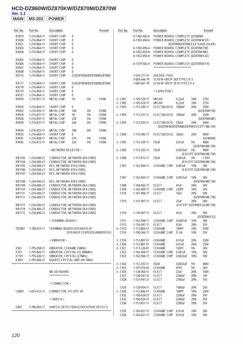
Ref. No. Part No. Description Remark Ref. No. Part No. Description Remark
HCD-DZ860W/DZ870KW/DZ870M/DZ870W
120
R3919 1-216-864-11 SHORT CHIP 0 R3920 1-216-864-11 SHORT CHIP 0 R3921 1-216-864-11 SHORT CHIP 0 R4503 1-216-864-11 SHORT CHIP 0 R4504 1-216-864-11 SHORT CHIP 0
R4505 1-216-864-11 SHORT CHIP 0 R4506 1-216-864-11 SHORT CHIP 0 R4507 1-216-864-11 SHORT CHIP 0 R4508 1-216-864-11 SHORT CHIP 0 R4716 1-216-864-11 SHORT CHIP 0 (DZ870KW/DZ870M/DZ870W)
R4717 1-216-864-11 SHORT CHIP 0 (DZ870KW/DZ870M/DZ870W) R4718 1-216-864-11 SHORT CHIP 0 R4719 1-216-864-11 SHORT CHIP 0 R4721 1-216-864-11 SHORT CHIP 0 R9918 1-216-821-11 METAL CHIP 1K 5% 1/10W
R9920 1-216-864-11 SHORT CHIP 0 R9922 1-216-833-11 METAL CHIP 10K 5% 1/10W R9924 1-216-821-11 METAL CHIP 1K 5% 1/10W R9928 1-216-837-11 METAL CHIP 22K 5% 1/10W R9929 1-216-837-11 METAL CHIP 22K 5% 1/10W
R9934 1-216-833-11 METAL CHIP 10K 5% 1/10W R9935 1-216-864-11 SHORT CHIP 0 R9941 1-216-838-11 METAL CHIP 27K 5% 1/10W R9945 1-216-813-11 METAL CHIP 220 5% 1/10W
< NETWORK RESISTOR >
RB1103 1-234-400-21 CONDUCTOR, NETWORK 0X4 (1005) RB1104 1-234-400-21 CONDUCTOR, NETWORK 0X4 (1005) RB1105 1-234-944-21 RES, NETWORK 47X4 (1005) RB1106 1-234-944-21 RES, NETWORK 47X4 (1005) RB1107 1-234-944-21 RES, NETWORK 47X4 (1005)
RB1108 1-234-944-21 RES, NETWORK 47X4 (1005) RB1109 1-234-400-21 CONDUCTOR, NETWORK 0X4 (1005) RB1110 1-234-400-21 CONDUCTOR, NETWORK 0X4 (1005) RB1111 1-234-400-21 CONDUCTOR, NETWORK 0X4 (1005) RB1112 1-234-400-21 CONDUCTOR, NETWORK 0X4 (1005)
RB1113 1-234-400-21 CONDUCTOR, NETWORK 0X4 (1005) RB1114 1-234-400-21 CONDUCTOR, NETWORK 0X4 (1005) RB1115 1-234-400-21 CONDUCTOR, NETWORK 0X4 (1005)
< TERMINAL BOARD >
TB3901 1-780-453-11 TERMINAL BOARD (SPEAKER) 2P (SPEAKER CENTER/SUBWOOFER)
< VIBRATOR >
X501 1-795-058-21 VIBRATOR, CERAMIC (5MHz) X701 1-795-843-11 VIBRATOR, CRYSTAL (12.288MHz) X1101 1-795-630-11 VIBRATOR, CRYSTAL (27MHz) X3051 1-795-660-21 QUARTZ CRYSTAL UNIT (49.1MHz)*************************************************************
MS-203 BOARD ************
< CONNECTOR >
CN001 1-815-412-11 CONNECTOR, FFC/FPC 5P
< SWITCH >
S001 1-786-693-11 SWITCH, DETECTION (CHUCK/TRAY DETECT)*************************************************************
A-1382-402-A POWER BOARD, COMPLETE (DZ860W) A-1392-694-A POWER BOARD, COMPLETE (DZ870KW:SP/ DZ870M/DZ870W:E3,E15,AUS,EA,KR) A-1392-696-A POWER BOARD, COMPLETE (DZ870W:TW) A-1452-054-A POWER BOARD, COMPLETE (DZ870W:MX) A-1452-056-A POWER BOARD, COMPLETE (DZ870W:E32)
A-1519-582-A POWER BOARD, COMPLETE (DZ870KW:TH) ***********************
1-533-217-41 HOLDER, FUSE 7-685-646-79 SCREW +BVTP 3X8 TYPE2 IT-3 7-685-647-79 SCREW +BVTP 3X10 TYPE2 IT-3
< CAPACITOR >
0 C901 1-165-529-11 MYLAR 0.22uF 10% 275V0 C902 1-165-529-11 MYLAR 0.22uF 10% 275V0 C903 1-112-330-11 ELECT(BLOCK) 1000uF 20% 200V (DZ870W:TW)0 C903 1-112-331-11 ELECT(BLOCK) 1000uF 20% 250V (DZ870W:MX)0 C903 1-112-333-11 ELECT(BLOCK) 330uF 20% 450V (DZ870KW/DZ870M/DZ870W:EXCEPT MX,TW)
0 C903 1-114-346-11 ELECT(BLOCK) 330uF 20% 400V (DZ860W)0 C905 1-112-334-11 FILM 0.01uF 5% 400V (DZ870W:MX,TW)0 C905 1-112-335-11 FILM 0.0033uF 5% 400V (EXCEPT DZ870W:MX,TW)0 C906 1-117-815-11 FILM 0.001uF 3% 1.5KV (EXCEPT DZ870W:MX,TW) C907 1-162-964-11 CERAMIC CHIP 0.001uF 10% 50V (EXCEPT DZ870W:MX,TW)
C907 1-162-965-11 CERAMIC CHIP 0.0015uF 10% 50V (DZ870W:MX,TW) C908 1-104-962-11 ELECT 47uF 20% 35V C909 1-162-960-11 CERAMIC CHIP 220PF 10% 50V C910 1-107-906-11 ELECT 10uF 20% 50V (DZ870W:MX,TW) C910 1-107-907-11 ELECT 22uF 20% 50V (EXCEPT DZ870W:E32,MX,TW)
C910 1-126-967-11 ELECT 47uF 20% 50V (DZ870W:E32) C911 1-162-968-11 CERAMIC CHIP 0.0047uF 10% 50V C912 1-126-947-11 ELECT 47uF 20% 35V0 C913 1-112-866-51 CERAMIC 100PF 10% 250V C916 1-100-566-11 CERAMIC CHIP 0.1uF 10% 25V
0 C918 1-112-887-51 CERAMIC 0.01uF 20% 250V0 C920 1-112-887-51 CERAMIC 0.01uF 20% 250V0 C921 1-117-220-81 CERAMIC 150PF 5% 2KV C922 1-162-964-11 CERAMIC CHIP 0.001uF 10% 50V C923 1-162-966-11 CERAMIC CHIP 0.0022uF 10% 50V
0 C924 1-112-335-11 FILM 0.0033uF 5% 400V0 C925 1-107-974-81 CERAMIC 47PF 5% 2KV0 C926 1-128-560-11 ELECT 22uF 20% 100V C927 1-128-947-31 ELECT 3300uF 20% 10V C928 1-137-947-21 ELECT 2700uF 20% 16V
C929 1-128-954-11 ELECT 1000uF 20% 25V0 C930 1-112-866-51 CERAMIC 100PF 10% 250V C932 1-100-924-21 ELECT 2200uF 20% 35V C933 1-100-924-21 ELECT 2200uF 20% 35V C934 1-112-831-11 ELECT 2200uF 20% 35V
C935 1-163-021-11 CERAMIC CHIP 0.01uF 10% 50V C936 1-163-021-11 CERAMIC CHIP 0.01uF 10% 50V
POWERMS-203MAINVer. 1.1
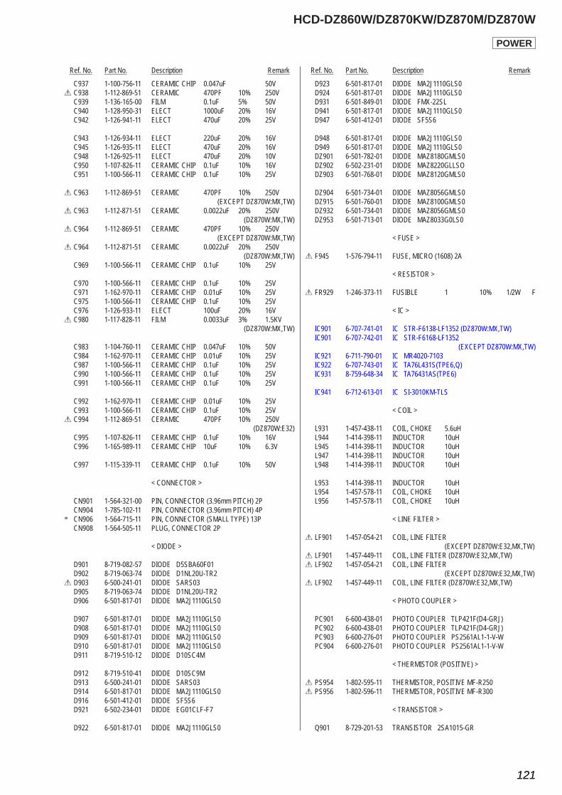
Ref. No. Part No. Description Remark Ref. No. Part No. Description Remark
HCD-DZ860W/DZ870KW/DZ870M/DZ870W
121121
C937 1-100-756-11 CERAMIC CHIP 0.047uF 50V0 C938 1-112-869-51 CERAMIC 470PF 10% 250V C939 1-136-165-00 FILM 0.1uF 5% 50V C940 1-128-950-31 ELECT 1000uF 20% 16V C942 1-126-941-11 ELECT 470uF 20% 25V
C943 1-126-934-11 ELECT 220uF 20% 16V C945 1-126-935-11 ELECT 470uF 20% 16V C948 1-126-925-11 ELECT 470uF 20% 10V C950 1-107-826-11 CERAMIC CHIP 0.1uF 10% 16V C951 1-100-566-11 CERAMIC CHIP 0.1uF 10% 25V
0 C963 1-112-869-51 CERAMIC 470PF 10% 250V (EXCEPT DZ870W:MX,TW)0 C963 1-112-871-51 CERAMIC 0.0022uF 20% 250V (DZ870W:MX,TW)0 C964 1-112-869-51 CERAMIC 470PF 10% 250V (EXCEPT DZ870W:MX,TW)0 C964 1-112-871-51 CERAMIC 0.0022uF 20% 250V (DZ870W:MX,TW) C969 1-100-566-11 CERAMIC CHIP 0.1uF 10% 25V
C970 1-100-566-11 CERAMIC CHIP 0.1uF 10% 25V C971 1-162-970-11 CERAMIC CHIP 0.01uF 10% 25V C975 1-100-566-11 CERAMIC CHIP 0.1uF 10% 25V C976 1-126-933-11 ELECT 100uF 20% 16V0 C980 1-117-828-11 FILM 0.0033uF 3% 1.5KV (DZ870W:MX,TW)
C983 1-104-760-11 CERAMIC CHIP 0.047uF 10% 50V C984 1-162-970-11 CERAMIC CHIP 0.01uF 10% 25V C987 1-100-566-11 CERAMIC CHIP 0.1uF 10% 25V C990 1-100-566-11 CERAMIC CHIP 0.1uF 10% 25V C991 1-100-566-11 CERAMIC CHIP 0.1uF 10% 25V
C992 1-162-970-11 CERAMIC CHIP 0.01uF 10% 25V C993 1-100-566-11 CERAMIC CHIP 0.1uF 10% 25V0 C994 1-112-869-51 CERAMIC 470PF 10% 250V (DZ870W:E32) C995 1-107-826-11 CERAMIC CHIP 0.1uF 10% 16V C996 1-165-989-11 CERAMIC CHIP 10uF 10% 6.3V
C997 1-115-339-11 CERAMIC CHIP 0.1uF 10% 50V
< CONNECTOR >
CN901 1-564-321-00 PIN, CONNECTOR (3.96mm PITCH) 2P CN904 1-785-102-11 PIN, CONNECTOR (3.96mm PITCH) 4P* CN906 1-564-715-11 PIN, CONNECTOR (SMALL TYPE) 13P CN908 1-564-505-11 PLUG, CONNECTOR 2P
< DIODE >
D901 8-719-082-57 DIODE D5SBA60F01 D902 8-719-063-74 DIODE D1NL20U-TR20 D903 6-500-241-01 DIODE SARS03 D905 8-719-063-74 DIODE D1NL20U-TR2 D906 6-501-817-01 DIODE MA2J1110GLS0
D907 6-501-817-01 DIODE MA2J1110GLS0 D908 6-501-817-01 DIODE MA2J1110GLS0 D909 6-501-817-01 DIODE MA2J1110GLS0 D910 6-501-817-01 DIODE MA2J1110GLS0 D911 8-719-510-12 DIODE D10SC4M
D912 8-719-510-41 DIODE D10SC9M D913 6-500-241-01 DIODE SARS03 D914 6-501-817-01 DIODE MA2J1110GLS0 D916 6-501-412-01 DIODE SF5S6 D921 6-502-234-01 DIODE EG01CLF-F7
D922 6-501-817-01 DIODE MA2J1110GLS0
D923 6-501-817-01 DIODE MA2J1110GLS0 D924 6-501-817-01 DIODE MA2J1110GLS0 D931 6-501-849-01 DIODE FMX-22SL D941 6-501-817-01 DIODE MA2J1110GLS0 D947 6-501-412-01 DIODE SF5S6
D948 6-501-817-01 DIODE MA2J1110GLS0 D949 6-501-817-01 DIODE MA2J1110GLS0 DZ901 6-501-782-01 DIODE MAZ8180GMLS0 DZ902 6-502-231-01 DIODE MAZ8220GLLSO DZ903 6-501-768-01 DIODE MAZ8120GMLS0
DZ904 6-501-734-01 DIODE MAZ8056GMLS0 DZ915 6-501-760-01 DIODE MAZ8100GMLS0 DZ932 6-501-734-01 DIODE MAZ8056GMLS0 DZ953 6-501-713-01 DIODE MAZ8033G0LS0
< FUSE >
0 F945 1-576-794-11 FUSE, MICRO (1608) 2A
< RESISTOR >
0 FR929 1-246-373-11 FUSIBLE 1 10% 1/2W F
< IC >
IC901 6-707-741-01 IC STR-F6138-LF1352 (DZ870W:MX,TW) IC901 6-707-742-01 IC STR-F6168-LF1352 (EXCEPT DZ870W:MX,TW) IC921 6-711-790-01 IC MR4020-7103 IC922 6-707-743-01 IC TA76L431S(TPE6,Q) IC931 8-759-648-34 IC TA76431AS(TPE6)
IC941 6-712-613-01 IC SI-3010KM-TLS
< COIL >
L931 1-457-438-11 COIL, CHOKE 5.6uH L944 1-414-398-11 INDUCTOR 10uH L945 1-414-398-11 INDUCTOR 10uH L947 1-414-398-11 INDUCTOR 10uH L948 1-414-398-11 INDUCTOR 10uH
L953 1-414-398-11 INDUCTOR 10uH L954 1-457-578-11 COIL, CHOKE 10uH L956 1-457-578-11 COIL, CHOKE 10uH
< LINE FILTER >
0 LF901 1-457-054-21 COIL, LINE FILTER (EXCEPT DZ870W:E32,MX,TW)0 LF901 1-457-449-11 COIL, LINE FILTER (DZ870W:E32,MX,TW)0 LF902 1-457-054-21 COIL, LINE FILTER (EXCEPT DZ870W:E32,MX,TW)0 LF902 1-457-449-11 COIL, LINE FILTER (DZ870W:E32,MX,TW)
< PHOTO COUPLER >
PC901 6-600-438-01 PHOTO COUPLER TLP421F(D4-GRJ) PC902 6-600-438-01 PHOTO COUPLER TLP421F(D4-GRJ) PC903 6-600-276-01 PHOTO COUPLER PS2561AL1-1-V-W PC904 6-600-276-01 PHOTO COUPLER PS2561AL1-1-V-W
< THERMISTOR (POSITIVE) >
0 PS954 1-802-595-11 THERMISTOR, POSITIVE MF-R2500 PS956 1-802-596-11 THERMISTOR, POSITIVE MF-R300
< TRANSISTOR >
Q901 8-729-201-53 TRANSISTOR 2SA1015-GR
POWER
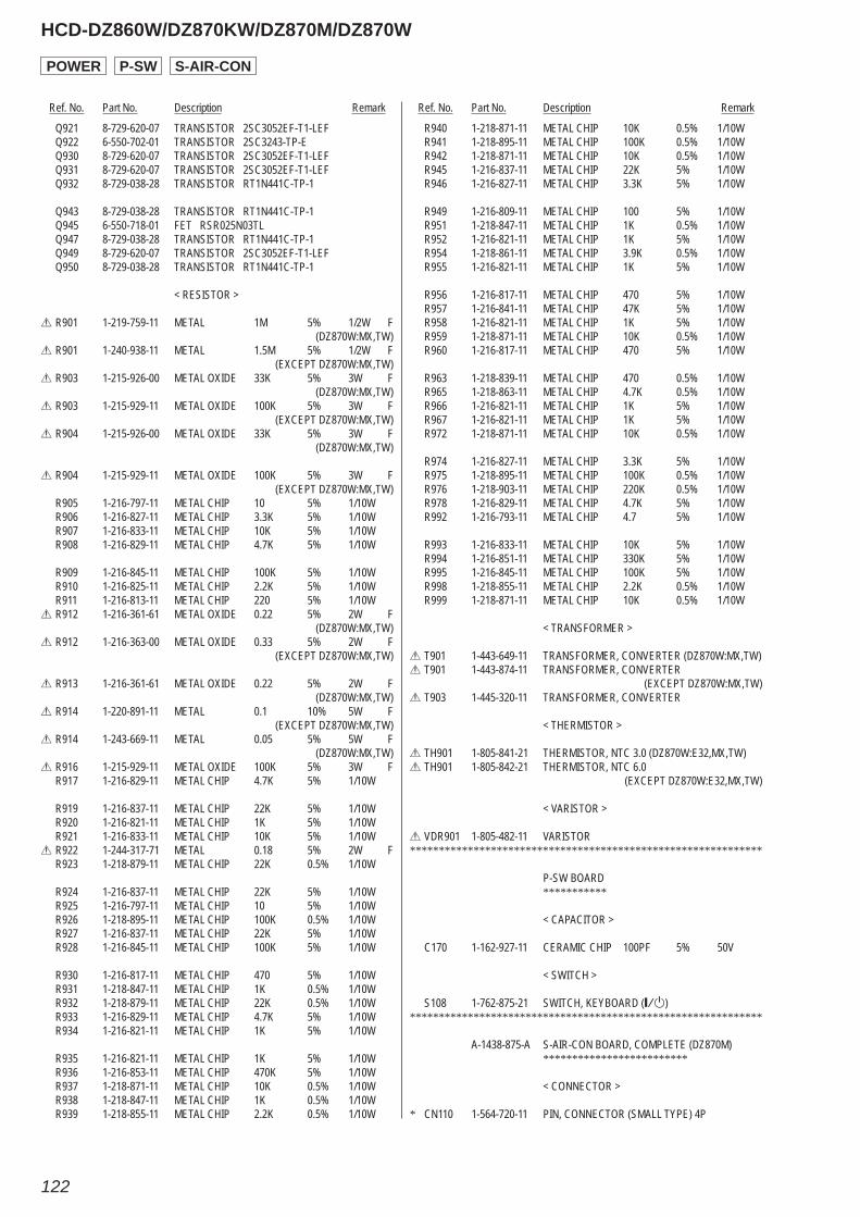
Ref. No. Part No. Description Remark Ref. No. Part No. Description Remark
HCD-DZ860W/DZ870KW/DZ870M/DZ870W
122
Q921 8-729-620-07 TRANSISTOR 2SC3052EF-T1-LEF Q922 6-550-702-01 TRANSISTOR 2SC3243-TP-E Q930 8-729-620-07 TRANSISTOR 2SC3052EF-T1-LEF Q931 8-729-620-07 TRANSISTOR 2SC3052EF-T1-LEF Q932 8-729-038-28 TRANSISTOR RT1N441C-TP-1
Q943 8-729-038-28 TRANSISTOR RT1N441C-TP-1 Q945 6-550-718-01 FET RSR025N03TL Q947 8-729-038-28 TRANSISTOR RT1N441C-TP-1 Q949 8-729-620-07 TRANSISTOR 2SC3052EF-T1-LEF Q950 8-729-038-28 TRANSISTOR RT1N441C-TP-1
< RESISTOR >
0 R901 1-219-759-11 METAL 1M 5% 1/2W F (DZ870W:MX,TW)0 R901 1-240-938-11 METAL 1.5M 5% 1/2W F (EXCEPT DZ870W:MX,TW)0 R903 1-215-926-00 METAL OXIDE 33K 5% 3W F (DZ870W:MX,TW)0 R903 1-215-929-11 METAL OXIDE 100K 5% 3W F (EXCEPT DZ870W:MX,TW)0 R904 1-215-926-00 METAL OXIDE 33K 5% 3W F (DZ870W:MX,TW)
0 R904 1-215-929-11 METAL OXIDE 100K 5% 3W F (EXCEPT DZ870W:MX,TW) R905 1-216-797-11 METAL CHIP 10 5% 1/10W R906 1-216-827-11 METAL CHIP 3.3K 5% 1/10W R907 1-216-833-11 METAL CHIP 10K 5% 1/10W R908 1-216-829-11 METAL CHIP 4.7K 5% 1/10W
R909 1-216-845-11 METAL CHIP 100K 5% 1/10W R910 1-216-825-11 METAL CHIP 2.2K 5% 1/10W R911 1-216-813-11 METAL CHIP 220 5% 1/10W0 R912 1-216-361-61 METAL OXIDE 0.22 5% 2W F (DZ870W:MX,TW)0 R912 1-216-363-00 METAL OXIDE 0.33 5% 2W F (EXCEPT DZ870W:MX,TW)
0 R913 1-216-361-61 METAL OXIDE 0.22 5% 2W F (DZ870W:MX,TW)0 R914 1-220-891-11 METAL 0.1 10% 5W F (EXCEPT DZ870W:MX,TW)0 R914 1-243-669-11 METAL 0.05 5% 5W F (DZ870W:MX,TW)0 R916 1-215-929-11 METAL OXIDE 100K 5% 3W F R917 1-216-829-11 METAL CHIP 4.7K 5% 1/10W
R919 1-216-837-11 METAL CHIP 22K 5% 1/10W R920 1-216-821-11 METAL CHIP 1K 5% 1/10W R921 1-216-833-11 METAL CHIP 10K 5% 1/10W0 R922 1-244-317-71 METAL 0.18 5% 2W F R923 1-218-879-11 METAL CHIP 22K 0.5% 1/10W
R924 1-216-837-11 METAL CHIP 22K 5% 1/10W R925 1-216-797-11 METAL CHIP 10 5% 1/10W R926 1-218-895-11 METAL CHIP 100K 0.5% 1/10W R927 1-216-837-11 METAL CHIP 22K 5% 1/10W R928 1-216-845-11 METAL CHIP 100K 5% 1/10W
R930 1-216-817-11 METAL CHIP 470 5% 1/10W R931 1-218-847-11 METAL CHIP 1K 0.5% 1/10W R932 1-218-879-11 METAL CHIP 22K 0.5% 1/10W R933 1-216-829-11 METAL CHIP 4.7K 5% 1/10W R934 1-216-821-11 METAL CHIP 1K 5% 1/10W
R935 1-216-821-11 METAL CHIP 1K 5% 1/10W R936 1-216-853-11 METAL CHIP 470K 5% 1/10W R937 1-218-871-11 METAL CHIP 10K 0.5% 1/10W R938 1-218-847-11 METAL CHIP 1K 0.5% 1/10W R939 1-218-855-11 METAL CHIP 2.2K 0.5% 1/10W
R940 1-218-871-11 METAL CHIP 10K 0.5% 1/10W R941 1-218-895-11 METAL CHIP 100K 0.5% 1/10W R942 1-218-871-11 METAL CHIP 10K 0.5% 1/10W R945 1-216-837-11 METAL CHIP 22K 5% 1/10W R946 1-216-827-11 METAL CHIP 3.3K 5% 1/10W
R949 1-216-809-11 METAL CHIP 100 5% 1/10W R951 1-218-847-11 METAL CHIP 1K 0.5% 1/10W R952 1-216-821-11 METAL CHIP 1K 5% 1/10W R954 1-218-861-11 METAL CHIP 3.9K 0.5% 1/10W R955 1-216-821-11 METAL CHIP 1K 5% 1/10W
R956 1-216-817-11 METAL CHIP 470 5% 1/10W R957 1-216-841-11 METAL CHIP 47K 5% 1/10W R958 1-216-821-11 METAL CHIP 1K 5% 1/10W R959 1-218-871-11 METAL CHIP 10K 0.5% 1/10W R960 1-216-817-11 METAL CHIP 470 5% 1/10W
R963 1-218-839-11 METAL CHIP 470 0.5% 1/10W R965 1-218-863-11 METAL CHIP 4.7K 0.5% 1/10W R966 1-216-821-11 METAL CHIP 1K 5% 1/10W R967 1-216-821-11 METAL CHIP 1K 5% 1/10W R972 1-218-871-11 METAL CHIP 10K 0.5% 1/10W
R974 1-216-827-11 METAL CHIP 3.3K 5% 1/10W R975 1-218-895-11 METAL CHIP 100K 0.5% 1/10W R976 1-218-903-11 METAL CHIP 220K 0.5% 1/10W R978 1-216-829-11 METAL CHIP 4.7K 5% 1/10W R992 1-216-793-11 METAL CHIP 4.7 5% 1/10W
R993 1-216-833-11 METAL CHIP 10K 5% 1/10W R994 1-216-851-11 METAL CHIP 330K 5% 1/10W R995 1-216-845-11 METAL CHIP 100K 5% 1/10W R998 1-218-855-11 METAL CHIP 2.2K 0.5% 1/10W R999 1-218-871-11 METAL CHIP 10K 0.5% 1/10W
< TRANSFORMER >
0 T901 1-443-649-11 TRANSFORMER, CONVERTER (DZ870W:MX,TW)0 T901 1-443-874-11 TRANSFORMER, CONVERTER (EXCEPT DZ870W:MX,TW)0 T903 1-445-320-11 TRANSFORMER, CONVERTER
< THERMISTOR >
0 TH901 1-805-841-21 THERMISTOR, NTC 3.0 (DZ870W:E32,MX,TW)0 TH901 1-805-842-21 THERMISTOR, NTC 6.0 (EXCEPT DZ870W:E32,MX,TW)
< VARISTOR >
0 VDR901 1-805-482-11 VARISTOR*************************************************************
P-SW BOARD ***********
< CAPACITOR >
C170 1-162-927-11 CERAMIC CHIP 100PF 5% 50V
< SWITCH >
S108 1-762-875-21 SWITCH, KEYBOARD (|/1)*************************************************************
A-1438-875-A S-AIR-CON BOARD, COMPLETE (DZ870M) *************************
< CONNECTOR >
* CN110 1-564-720-11 PIN, CONNECTOR (SMALL TYPE) 4P
POWER P-SW S-AIR-CON
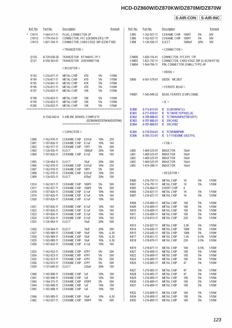
Ref. No. Part No. Description Remark Ref. No. Part No. Description Remark
HCD-DZ860W/DZ870KW/DZ870M/DZ870W
123123
* CN111 1-564-517-11 PLUG, CONNECTOR 2P CN112 1-779-554-21 CONNECTOR, FFC (LIF(NON-ZIF)) 17P CN113 1-821-744-11 CONNECTOR, CARD EDGE 30P (EZW-T100)
< TRANSISTOR >
Q120 8-729-038-28 TRANSISTOR RT1N441C-TP-1 Q121 6-550-363-01 TRANSISTOR 2SB1690KT146
< RESISTOR >
R193 1-216-817-11 METAL CHIP 470 5% 1/10W R194 1-216-817-11 METAL CHIP 470 5% 1/10W R195 1-216-841-11 METAL CHIP 47K 5% 1/10W R196 1-216-817-11 METAL CHIP 470 5% 1/10W R197 1-216-833-11 METAL CHIP 10K 5% 1/10W
R198 1-216-833-11 METAL CHIP 10K 5% 1/10W R199 1-216-833-11 METAL CHIP 10K 5% 1/10W R200 1-216-833-11 METAL CHIP 10K 5% 1/10W*************************************************************
A-1542-042-A S-AIR-INC BOARD, COMPLETE (DZ860W/DZ870KW/DZ870W) ************************
< CAPACITOR >
C800 1-162-970-11 CERAMIC CHIP 0.01uF 10% 25V C801 1-107-826-11 CERAMIC CHIP 0.1uF 10% 16V C802 1-162-917-11 CERAMIC CHIP 15PF 5% 50V C803 1-126-926-11 ELECT 1000uF 20% 10V C804 1-107-826-11 CERAMIC CHIP 0.1uF 10% 16V
C805 1-126-964-11 ELECT 10uF 20% 50V C806 1-162-970-11 CERAMIC CHIP 0.01uF 10% 25V C807 1-162-918-11 CERAMIC CHIP 18PF 5% 50V C808 1-162-970-11 CERAMIC CHIP 0.01uF 10% 25V C809 1-126-925-11 ELECT 470uF 20% 10V
C814 1-162-927-11 CERAMIC CHIP 100PF 5% 50V C817 1-162-927-11 CERAMIC CHIP 100PF 5% 50V C818 1-107-826-11 CERAMIC CHIP 0.1uF 10% 16V C819 1-107-826-11 CERAMIC CHIP 0.1uF 10% 16V C820 1-107-826-11 CERAMIC CHIP 0.1uF 10% 16V
C821 1-107-826-11 CERAMIC CHIP 0.1uF 10% 16V C822 1-107-826-11 CERAMIC CHIP 0.1uF 10% 16V C823 1-107-826-11 CERAMIC CHIP 0.1uF 10% 16V C824 1-107-826-11 CERAMIC CHIP 0.1uF 10% 16V C825 1-126-964-11 ELECT 10uF 20% 50V
C826 1-126-964-11 ELECT 10uF 20% 50V C827 1-165-989-11 CERAMIC CHIP 10uF 10% 6.3V C828 1-165-989-11 CERAMIC CHIP 10uF 10% 6.3V C829 1-165-989-11 CERAMIC CHIP 10uF 10% 6.3V C830 1-107-826-11 CERAMIC CHIP 0.1uF 10% 16V
C833 1-162-923-11 CERAMIC CHIP 47PF 5% 50V C834 1-162-923-11 CERAMIC CHIP 47PF 5% 50V C835 1-162-923-11 CERAMIC CHIP 47PF 5% 50V C836 1-162-923-11 CERAMIC CHIP 47PF 5% 50V C839 1-137-649-31 ELECT 220uF 20% 10V
C840 1-165-908-11 CERAMIC CHIP 1uF 10% 10V C841 1-165-908-11 CERAMIC CHIP 1uF 10% 10V C843 1-164-315-11 CERAMIC CHIP 470PF 5% 50V C844 1-165-908-11 CERAMIC CHIP 1uF 10% 10V C845 1-165-908-11 CERAMIC CHIP 1uF 10% 10V
C846 1-165-989-11 CERAMIC CHIP 10uF 10% 6.3V C882 1-162-927-11 CERAMIC CHIP 100PF 5% 50V
C885 1-162-927-11 CERAMIC CHIP 100PF 5% 50V C886 1-162-927-11 CERAMIC CHIP 100PF 5% 50V C888 1-126-926-11 ELECT 1000uF 20% 10V
< CONNECTOR >
CN800 1-820-116-41 CONNECTOR, FFC/FPC 17P CN803 1-821-747-11 CONNECTOR, CARD EDGE 20P (L) (EZW-RT10) CN804 1-564-706-11 PIN, CONNECTOR (SMALL TYPE) 4P
< DIODE >
D800 6-501-579-01 DIODE MC2837
< FERRITE BEAD >
FB801 1-543-949-22 BEAD, FERRITE (CHIP) (1608)
< IC >
IC800 6-712-613-01 IC SI-3010KM-TLS IC801 6-711-418-01 IC TC74VHC157FK(EL,K) IC802 6-709-888-01 IC TC7WHU04FK(T5RSOYF) IC803 6-707-800-01 IC SRC4182 IC804 6-707-800-01 IC SRC4182
IC805 6-710-554-01 IC PCM1808PWR IC806 6-705-312-01 IC S-T111B33MC-OGSTFG
< COIL >
L800 1-469-525-91 INDUCTOR 10uH L801 1-469-525-91 INDUCTOR 10uH L802 1-469-525-91 INDUCTOR 10uH L803 1-469-525-91 INDUCTOR 10uH L805 1-414-398-11 INDUCTOR 10uH
< RESISTOR >
R800 1-216-797-11 METAL CHIP 10 5% 1/10W R801 1-216-797-11 METAL CHIP 10 5% 1/10W R805 1-216-864-11 SHORT CHIP 0 R806 1-216-821-11 METAL CHIP 1K 5% 1/10W R807 1-216-821-11 METAL CHIP 1K 5% 1/10W
R808 1-216-809-11 METAL CHIP 100 5% 1/10W R809 1-216-809-11 METAL CHIP 100 5% 1/10W R810 1-216-809-11 METAL CHIP 100 5% 1/10W R811 1-216-809-11 METAL CHIP 100 5% 1/10W R812 1-216-813-11 METAL CHIP 220 5% 1/10W
R813 1-216-827-11 METAL CHIP 3.3K 5% 1/10W R814 1-216-845-11 METAL CHIP 100K 5% 1/10W R815 1-216-845-11 METAL CHIP 100K 5% 1/10W R817 1-218-851-11 METAL CHIP 1.5K 0.5% 1/10W R818 1-218-879-11 METAL CHIP 22K 0.5% 1/10W
R819 1-218-871-11 METAL CHIP 10K 0.5% 1/10W R821 1-216-809-11 METAL CHIP 100 5% 1/10W R822 1-216-809-11 METAL CHIP 100 5% 1/10W R824 1-216-809-11 METAL CHIP 100 5% 1/10W R826 1-216-805-11 METAL CHIP 47 5% 1/10W
R827 1-216-805-11 METAL CHIP 47 5% 1/10W R828 1-216-805-11 METAL CHIP 47 5% 1/10W R829 1-216-809-11 METAL CHIP 100 5% 1/10W R830 1-216-809-11 METAL CHIP 100 5% 1/10W R831 1-216-809-11 METAL CHIP 100 5% 1/10W
R832 1-216-809-11 METAL CHIP 100 5% 1/10W R834 1-216-809-11 METAL CHIP 100 5% 1/10W R835 1-216-809-11 METAL CHIP 100 5% 1/10W
S-AIR-INCS-AIR-CON
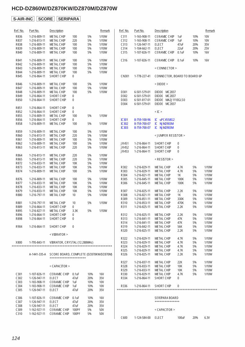
Ref. No. Part No. Description Remark Ref. No. Part No. Description Remark
HCD-DZ860W/DZ870KW/DZ870M/DZ870W
124
R836 1-216-809-11 METAL CHIP 100 5% 1/10W R837 1-216-813-11 METAL CHIP 220 5% 1/10W R838 1-216-809-11 METAL CHIP 100 5% 1/10W R839 1-216-809-11 METAL CHIP 100 5% 1/10W R840 1-216-809-11 METAL CHIP 100 5% 1/10W
R841 1-216-809-11 METAL CHIP 100 5% 1/10W R842 1-216-809-11 METAL CHIP 100 5% 1/10W R843 1-216-809-11 METAL CHIP 100 5% 1/10W R844 1-216-809-11 METAL CHIP 100 5% 1/10W R845 1-216-864-11 SHORT CHIP 0
R846 1-216-809-11 METAL CHIP 100 5% 1/10W R847 1-216-809-11 METAL CHIP 100 5% 1/10W R848 1-216-809-11 METAL CHIP 100 5% 1/10W R849 1-216-864-11 SHORT CHIP 0 R850 1-216-864-11 SHORT CHIP 0
R851 1-216-864-11 SHORT CHIP 0 R852 1-216-864-11 SHORT CHIP 0 R855 1-216-809-11 METAL CHIP 100 5% 1/10W R856 1-216-864-11 SHORT CHIP 0 R858 1-216-809-11 METAL CHIP 100 5% 1/10W
R859 1-216-809-11 METAL CHIP 100 5% 1/10W R860 1-216-813-11 METAL CHIP 220 5% 1/10W R861 1-216-809-11 METAL CHIP 100 5% 1/10W R862 1-216-809-11 METAL CHIP 100 5% 1/10W R863 1-216-813-11 METAL CHIP 220 5% 1/10W
R864 1-216-813-11 METAL CHIP 220 5% 1/10W R865 1-216-813-11 METAL CHIP 220 5% 1/10W R872 1-216-833-11 METAL CHIP 10K 5% 1/10W R873 1-216-833-11 METAL CHIP 10K 5% 1/10W R874 1-216-809-11 METAL CHIP 100 5% 1/10W
R876 1-216-809-11 METAL CHIP 100 5% 1/10W R877 1-216-833-11 METAL CHIP 10K 5% 1/10W R878 1-216-833-11 METAL CHIP 10K 5% 1/10W R879 1-216-833-11 METAL CHIP 10K 5% 1/10W R880 1-216-797-11 METAL CHIP 10 5% 1/10W
R881 1-216-797-11 METAL CHIP 10 5% 1/10W R889 1-216-864-11 SHORT CHIP 0 R895 1-216-827-11 METAL CHIP 3.3K 5% 1/10W R896 1-216-864-11 SHORT CHIP 0 R898 1-216-864-11 SHORT CHIP 0
R904 1-216-864-11 SHORT CHIP 0
< VIBRATOR >
X800 1-795-843-11 VIBRATOR, CRYSTAL (12.288MHz)*************************************************************
A-1441-335-A SCORE BOARD, COMPLETE (DZ870KW/DZ870M) **********************
< CAPACITOR >
C301 1-107-826-11 CERAMIC CHIP 0.1uF 10% 16V C302 1-126-947-11 ELECT 47uF 20% 35V C303 1-165-908-11 CERAMIC CHIP 1uF 10% 10V C304 1-165-908-11 CERAMIC CHIP 1uF 10% 10V C305 1-126-947-11 ELECT 47uF 20% 35V
C306 1-107-826-11 CERAMIC CHIP 0.1uF 10% 16V C307 1-126-947-11 ELECT 47uF 20% 35V C308 1-126-947-11 ELECT 47uF 20% 35V C309 1-162-927-11 CERAMIC CHIP 100PF 5% 50V C310 1-162-927-11 CERAMIC CHIP 100PF 5% 50V
C311 1-165-908-11 CERAMIC CHIP 1uF 10% 10V C312 1-165-908-11 CERAMIC CHIP 1uF 10% 10V C313 1-126-947-11 ELECT 47uF 20% 35V C314 1-104-662-11 ELECT 22uF 20% 25V C315 1-107-826-11 CERAMIC CHIP 0.1uF 10% 16V
C316 1-107-826-11 CERAMIC CHIP 0.1uF 10% 16V
< CONNECTOR >
CN301 1-778-227-41 CONNECTOR, BOARD TO BOARD 6P
< DIODE >
D301 6-501-579-01 DIODE MC2837 D302 6-501-579-01 DIODE MC2837 D303 6-501-817-01 DIODE MA2J1110GLS0 D304 6-501-579-01 DIODE MC2837
< IC >
IC301 8-759-100-96 IC uPC4558G2 IC302 8-759-700-07 IC NJM2903M IC303 8-759-700-07 IC NJM2903M
< JUMPER RESISTOR >
JR451 1-216-864-11 SHORT CHIP 0 JR452 1-216-864-11 SHORT CHIP 0 JR453 1-216-864-11 SHORT CHIP 0
< RESISTOR >
R302 1-216-829-11 METAL CHIP 4.7K 5% 1/10W R303 1-216-829-11 METAL CHIP 4.7K 5% 1/10W R304 1-216-821-11 METAL CHIP 1K 5% 1/10W R305 1-216-845-11 METAL CHIP 100K 5% 1/10W R306 1-216-845-11 METAL CHIP 100K 5% 1/10W
R307 1-216-825-11 METAL CHIP 2.2K 5% 1/10W R308 1-216-821-11 METAL CHIP 1K 5% 1/10W R309 1-216-851-11 METAL CHIP 330K 5% 1/10W R310 1-216-853-11 METAL CHIP 470K 5% 1/10W R311 1-216-825-11 METAL CHIP 2.2K 5% 1/10W
R312 1-216-825-11 METAL CHIP 2.2K 5% 1/10W R313 1-216-841-11 METAL CHIP 47K 5% 1/10W R314 1-216-841-11 METAL CHIP 47K 5% 1/10W R319 1-216-842-11 METAL CHIP 56K 5% 1/10W R320 1-216-825-11 METAL CHIP 2.2K 5% 1/10W
R322 1-216-829-11 METAL CHIP 4.7K 5% 1/10W R323 1-216-829-11 METAL CHIP 4.7K 5% 1/10W R324 1-216-829-11 METAL CHIP 4.7K 5% 1/10W R325 1-216-829-11 METAL CHIP 4.7K 5% 1/10W R326 1-216-825-11 METAL CHIP 2.2K 5% 1/10W
R327 1-216-837-11 METAL CHIP 22K 5% 1/10W R328 1-216-833-11 METAL CHIP 10K 5% 1/10W R329 1-216-833-11 METAL CHIP 10K 5% 1/10W R330 1-216-829-11 METAL CHIP 4.7K 5% 1/10W R334 1-216-864-11 SHORT CHIP 0
R336 1-216-864-11 SHORT CHIP 0*************************************************************
SERIPARA BOARD ***************
< CAPACITOR >
C600 1-124-584-00 ELECT 100uF 20% 6.3V
S-AIR-INC SCORE SERIPARA
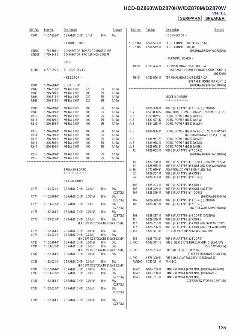
Ref. No. Part No. Description Remark Ref. No. Part No. Description Remark
HCD-DZ860W/DZ870KW/DZ870M/DZ870W
125125
C601 1-107-826-11 CERAMIC CHIP 0.1uF 10% 16V
< CONNECTOR >
CN600 1-764-865-41 CONNECTOR, BOARD TO BOARD 13P CN601 1-779-544-21 CONNECTOR, FFC (LIF(NON-ZIF)) 7P
< IC >
IC600 6-707-095-01 IC BH2210FV-E2
< RESISTOR >
R601 1-216-864-11 SHORT CHIP 0 R602 1-216-813-11 METAL CHIP 220 5% 1/10W R603 1-216-809-11 METAL CHIP 100 5% 1/10W R604 1-216-813-11 METAL CHIP 220 5% 1/10W R606 1-216-813-11 METAL CHIP 220 5% 1/10W
R608 1-216-809-11 METAL CHIP 100 5% 1/10W R609 1-216-809-11 METAL CHIP 100 5% 1/10W R610 1-216-809-11 METAL CHIP 100 5% 1/10W R611 1-216-809-11 METAL CHIP 100 5% 1/10W R612 1-216-809-11 METAL CHIP 100 5% 1/10W
R613 1-216-809-11 METAL CHIP 100 5% 1/10W R614 1-216-809-11 METAL CHIP 100 5% 1/10W R615 1-216-809-11 METAL CHIP 100 5% 1/10W R616 1-216-809-11 METAL CHIP 100 5% 1/10W R617 1-216-809-11 METAL CHIP 100 5% 1/10W
R618 1-216-809-11 METAL CHIP 100 5% 1/10W R619 1-216-809-11 METAL CHIP 100 5% 1/10W*************************************************************
SPEAKER BOARD **************
< CAPACITOR >
C173 1-163-021-11 CERAMIC CHIP 0.01uF 10% 50V (DZ870M) C174 1-162-964-11 CERAMIC CHIP 0.001uF 10% 50V (DZ870M) C175 1-163-021-11 CERAMIC CHIP 0.01uF 10% 50V (DZ870M) C176 1-162-964-11 CERAMIC CHIP 0.001uF 10% 50V (DZ870M) C177 1-163-021-11 CERAMIC CHIP 0.01uF 10% 50V (EXCEPT DZ870KW/DZ870W:E32,MX)
C178 1-162-964-11 CERAMIC CHIP 0.001uF 10% 50V C179 1-163-021-11 CERAMIC CHIP 0.01uF 10% 50V (EXCEPT DZ870KW/DZ870W:E32,MX) C180 1-162-964-11 CERAMIC CHIP 0.001uF 10% 50V C181 1-163-021-11 CERAMIC CHIP 0.01uF 10% 50V (EXCEPT DZ870KW/DZ870W:E32,MX) C182 1-162-964-11 CERAMIC CHIP 0.001uF 10% 50V
C183 1-163-021-11 CERAMIC CHIP 0.01uF 10% 50V (EXCEPT DZ870KW/DZ870W:E32,MX) C184 1-162-964-11 CERAMIC CHIP 0.001uF 10% 50V C185 1-163-021-11 CERAMIC CHIP 0.01uF 10% 50V (DZ870M) C186 1-162-964-11 CERAMIC CHIP 0.001uF 10% 50V (DZ870M) C187 1-163-021-11 CERAMIC CHIP 0.01uF 10% 50V (DZ870M)
C188 1-162-964-11 CERAMIC CHIP 0.001uF 10% 50V (DZ870M)
< CONNECTOR >
* CN114 1-564-523-11 PLUG, CONNECTOR 8P (DZ870M)* CN115 1-564-519-11 PLUG, CONNECTOR 4P (DZ860W/DZ870KW/DZ870W)
< TERMINAL BOARD >
TB100 1-780-454-11 TERMINAL BOARD (SPEAKER) 4P (SPEAKER FRONT R/FRONT L/SUR R/SUR L) (DZ870M) TB101 1-780-576-11 TERMINAL BOARD (SPEAKER) 2P (SPEAKER FRONT R/FRONT L) (DZ860W/DZ870KW/DZ870W)*************************************************************
MISCELLANEOUS **************
5 1-828-350-11 WIRE (FLAT TYPE) (17 CORE) (DZ870M)0 7 1-569-008-22 ADAPTOR, CONVERSION 2P (DZ870W:E15,E32)0 8 1-769-079-61 CORD, POWER (DZ870W:KR)0 8 1-827-597-42 CORD, POWER (DZ870W:TW)0 8 1-834-288-11 CORD, POWER (DZ870KW:TH)
0 8 1-834-966-21 CORD, POWER (DZ860W:AEP,CE2/DZ870KW:SP/ DZ870M/DZ870W:E3,E15,E32,EA)0 8 1-834-967-21 CORD, POWER (DZ870W:AUS)0 8 1-834-978-11 CORD, POWER (DZ870W:MX)0 8 1-835-078-21 CORD, POWER (DZ860W:UK) 12 1-828-002-11 WIRE (FLAT TYPE) (17 CORE) (DZ860W/DZ870KW/DZ870W)
14 1-827-720-11 WIRE (FLAT TYPE) (11 CORE) (DZ860W/DZ870M) 14 1-828-955-11 WIRE (FLAT TYPE) (9 CORE) (DZ870KW/DZ870W)0 16 1-770-019-61 ADAPTOR, CONVERSION PLUG (EA) 63 1-828-307-11 WIRE (FLAT TYPE) (9 CORE) 64 1-828-363-11 WIRE (FLAT TYPE) (19 CORE)
106 1-828-293-11 WIRE (FLAT TYPE) (5 CORE) 107 1-828-309-11 WIRE (FLAT TYPE) (9 CORE) (DZ870W) 107 1-828-319-11 WIRE (FLAT TYPE) (11 CORE) (DZ860W/DZ870KW) 107 1-828-329-11 WIRE (FLAT TYPE) (13 CORE) (DZ870M) 108 1-828-347-11 WIRE (FLAT TYPE) (17 CORE) (DZ870KW/DZ870M/DZ870W)
108 1-828-357-11 WIRE (FLAT TYPE) (19 CORE) (DZ860W) 111 1-828-299-11 WIRE (FLAT TYPE) (7 CORE) 117 1-828-287-11 WIRE (FLAT TYPE) (5 CORE) (DZ860W/DZ870W) 117 1-828-296-11 WIRE (FLAT TYPE) (7 CORE) (DZ870KW/DZ870M)0 157 8-820-321-05 OPTICAL PICK-UP KHM-313CAA/C2RP
158 1-828-773-51 WIRE (FLAT TYPE) (24 CORE)0 F901 1-533-311-12 FUSE, GLASS CYLINDRICAL (DIA. 5) (8A/125V) (DZ870W:MX,TW)0 F901 1-576-233-51 FUSE (H.B.C.) (T6.3AL/250V) (EXCEPT DZ870W:E32,MX,TW)0 F901 1-576-300-51 FUSE (H.B.C.) (T8AL/250V) (DZ870W:E32) FAN3001 1-787-331-11 FAN, D.C.
TU401 1-693-759-11 TUNER (FM/AM) (ANTENNA) (DZ860W/DZ870M) TU401 1-693-760-11 TUNER (FM/AM) (ANTENNA) (DZ870W:KR) TU401 1-693-761-11 TUNER (FM/AM) (ANTENNA) (DZ870KW/DZ870W:EXCEPT KR)
SPEAKERSERIPARAVer. 1.1

HCD-DZ860W/DZ870KW/DZ870M/DZ870W
REVISION HISTORY
Checking the version allows you to jump to the revised page.Also, clicking the version at the top of the revised page allows you to jump to the next revised page.
Ver. Date Description of Revision1.0 2008.04 New
1.1 2008.07 Addition of Saudi Arabia model to HCD-DZ870W.
Related Documents


![HCD-GTR6/GTR6B/GTR7/GTR8/GTR8B - Diagramas dediagramasde.com/diagramas/audio/HCD-GTR6_GTR7_GTR8[2].pdf · SERVICE MANUAL E Model HCD-GTR6/GTR6B/GTR7/GTR8/GTR8B Australian Model HCD-GTR6B/GTR8B](https://static.cupdf.com/doc/110x72/5adbb5627f8b9a52528e9889/hcd-gtr6gtr6bgtr7gtr8gtr8b-diagramas-2pdfservice-manual-e-model-hcd-gtr6gtr6bgtr7gtr8gtr8b.jpg)