On behalf of Project Ref: 24261/4001 | Rev: - | Date: May 2014 Office Address: 3rd Floor Waterloo House, Victoria Square, Birmingham B2 5TB T: +44 (0)121 633 2900 F: +44 (0)121 633 2901 E: [email protected] HBC Fields, Widnes Flood Risk Assessment

Welcome message from author
This document is posted to help you gain knowledge. Please leave a comment to let me know what you think about it! Share it to your friends and learn new things together.
Transcript

On behalf of
Project Ref: 24261/4001 | Rev: - | Date: May 2014
Office Address: 3rd Floor Waterloo House, Victoria Square, Birmingham B2 5TB T: +44 (0)121 633 2900 F: +44 (0)121 633 2901 E: [email protected]
HBC Fields, Widnes Flood Risk Assessment

Flood Risk Assessment HBC Fields, Widnes
J:\24261- HBC Fields, Widnes\24261 HBC Widnes 2014 work\Reports\2014 FRA\Project Tiger Widnes FRA 140520.docx
Appendix A Topographical Survey


Flood Risk Assessment HBC Fields, Widnes
J:\24261- HBC Fields, Widnes\24261 HBC Widnes 2014 work\Reports\2014 FRA\Project Tiger Widnes FRA 140520.docx
Appendix B Masterplan

Ha
leb
an
kR
ec
rea
tio
n G
rou
nd
9
17
2
72
68
66
115
135
127 to 137
62
Po
nd
11.9
mHA
LE B
AN
K R
OA
D
Nu
rse
ry
Po
nd
HE
AT
HV
IEW
CLO
SE
Ha
leb
an
k C
PS
ch
oo
l
BA
GU
LEY
AV
EN
UE
BA
GU
LEY
AV
EN
UEH
ale
ba
nk
Re
cre
ati
on
Gro
un
d
6462
6058
56
21
35
43
1
9
19
24
12
2
41
576361
59
73
85 87
89 91
99
111
62
50
34
20
6
21
35
40
30
Ta
nk
MP
.2
5
SP
Sig
na
l B
ox
Potters Lane
MP
.5
SL
s
HALE
BAN
K RO
AD
Ha
ve
loc
kC
ott
ag
es
Sm
ith
yH
ou
se
Lin
ne
r F
arm
12.3
m
Th
e B
ee
hiv
e I
nn
(PH
)
Lea Dale
Beech Lea Ashfie
ld Oakfield
Elmfie
ld Fairfie
ld
RoseleaElla
stone
11.3
m
Mid
dle
fie
ld
BM
11.
43m
POTTERS LANE
149
157
6866
Track
Linner F
arm
Cottage
LB
FF
RH
Euro Const Bdy
RH
Und
Eu
ro C
on
st
Bd
y
Ha
ve
loc
k
Lin
ne
r F
arm
Th
e B
ee
hiv
e I
nn
(PH
)
Linner F
arm
Cottage
MP
.5
SL
s
11.3
m
Track
LB
Sp
Sp
Sp
Sp
Sp
Sp
Sp
Sp
Bus
h
Bus
hBus
h
Bus
h
Bus
h
Bus
h
BH
BH
CPS07
Emergency Vehicles & Bus A
ccess Route
Bus s
top
incl. s
helter
Ris
ing b
arr
ier
with
associa
ted c
ard
readers
, bollard
sand p
ow
er
Relo
cate
d 'A'
fram
ein
pro
posed
fence lin
e
Bollard
s
cellula
r
rein
forc
ed
concre
te
roadw
ay w
ith
gra
ss infill
Tarm
ac p
ull-i
n
befo
re b
arr
ier
Reta
inin
g w
all
Bala
ncin
g P
ond B
As R
PS d
raw
ing S
K0315
Retaining wall
Security
contr
olled
pedestr
ian &
cycle
access
Security
contr
olled v
ehic
le,
pedestr
ian &
cycle
access
Sprinkle
rta
nks &
pum
phouse
Pote
ntial la
ndscape
are
a -
to b
edesig
ned b
yBCA/T
EP
Security
contr
olled
pedestr
ian
access
Indic
ative
landscape
bund -
to b
edesig
ned b
yBCA/T
EP
Indic
ative
landscape
bund -
to b
edesig
ned b
yBCA/T
EP
Security
contr
olled
pedestr
ian
access
Landscape a
rea -
as a
ppro
ved
pre
vio
usly
with
A562 L
ink R
oad
application
Security
contr
olled
pedestr
ian &
cycle
access
Waste
managem
ent
are
a -
siz
e T
BC
REACH
-STACKER O
PERATIO
N Z
ON
E
REACH
-STACKER O
PERATIO
N Z
ON
E
Pedestr
ian a
ccess r
oute
for
bridge &
pond
main
tenance -
TBC
15 H
GV
waitin
gspaces
RAIL
DESIG
N S
IDIN
GS A
S A
PPRO
VED
PLAN
NIN
G P
ERM
ISSIO
N 0
7/0
0362/F
UL
Gate
house
NEW
RAIL
SID
ING
S T
O B
E D
ESIG
NED
BY S
TO
BART R
AIL
Overf
low
car
park
450 s
paces (
tota
l)(s
how
n h
atc
hed)
224 c
ycle
s(1
/500 m
sq)
800 p
erm
anent
car
park
ing s
paces
(80 a
ccessib
le;
10%
of perm
anent)
32 m
oto
rcycle
s(1
/25 p
erm
anent
car
park
ing s
pace)
63 (
2+
car
share
) car
park
ing s
paces (
5%
of to
tal)
2.4
m h
igh
pala
din
fence
2.4
m h
igh
pala
din
fence
2.4
m h
igh
pala
din
fence
2.4
m h
igh
pala
din
fence
2.4
m h
igh
pala
din
fence
2.4
m h
igh
pala
din
fence
2.4
m h
igh
pala
din
fence
2.4
mhig
hpala
din
fence
2.4
m h
igh
pala
din
fence
2+2+2+2+2+2+2+
2+2+2+2+2+2+2+2+2+2+2+2+2+2+2+2+2+
2+
2+2+2+2+2+2+2+2+2+2+2+2+
2+2+
2+
2+2+
2+2+
2+2+2+2+2+2+2+2+2+2+2+
2+
2+
2+
2+2+2+
2+ 2+
Sm
okin
gshelters
(150sqm
)
pro
posed lim
itof adoption
pro
posed lim
it
of adoption
footp
ath
and
main
tenance
link
dk
2.0m maintenance path
2.0m maintenance path
2.0m maintenance path
2.0m maintenance path
2.0m maintenance path
2.0m maintenance path
6000
6000
Sub
Sta
tion
Gas
Gov.
6000m
m c
leara
nce u
nder
bridge lin
k -
TBC
3000m
m w
ide b
alc
ony a
t hig
h level
3000m
m w
ide b
alc
ony a
t hig
h level
Sta
ir1
Sta
ir 2
Sta
ir 4Sta
ir 5
Sta
ir 6
Sta
ir 7
Sta
ir 8
Sta
ir 9
Sta
ir 1
0
Sta
ir11
Sta
ir12
Sta
ir13
Sta
ir 3
1 L
.A.
1 F
ork
lift
tru
ck a
ccess
(3m
wid
e)
6 x
speed c
urt
ain
s
6 x
speed c
urt
ain
s
1 L
.A.
1 L
.A.
1 L
.A.
1 L
.A.
1 L
.A.
1 F
ork
lift
tru
ck a
ccess
(3m
wid
e)
1 F
ork
lift
tru
ck
access (
3m
wid
e)
1 L
.A.
1 L
.A.
1 L
.A.
1 L
.A.
1 L
.A.
1 L
.A.
1 s
peed c
urt
ain
1 level access d
oor
(5.2
5m
h x
6.5
m w
)
1 P
ers
onnel door
1 P
ers
onnel door
1 P
ers
onnel door
1 P
ers
onnel door
1 P
ers
onnel door
Goods
lift
Passenger
lift
Com
bin
ed
Passenger
&G
oods lift
Cle
anin
g p
it(1
500x1500)
Cle
anin
g p
it(1
500x1500)
Batt
ery
Charg
ing
Are
a
Batt
ery
Charg
ing
Are
aBatt
ery
Charg
ing
Are
a
Batt
ery
Charg
ing
Are
a
Batt
ery
Charg
ing
Are
a
Batt
ery
Charg
ing
Are
a
1 P
ers
onnel door
1 F
ork
lift
tru
ck
access (
3m
wid
e)
1 level access d
oor
(5.2
5m
h x
6.5
m w
)
Ware
house o
ffic
es
Ware
house o
ffic
es
WC &
Sta
ir c
ore
WC &
Sta
ir c
ore
WC &
Sta
ir c
ore
WC &
Sta
ir c
ore
Constr
uction a
nd
access d
eta
ils T
BC
Sta
ir &
lift
tow
er
Mezzanin
e o
ffic
e o
ver
Sprinkle
rta
nks &
pum
phouse
30 d
ocks (
4.2
5m
hig
h x
3m
wid
e)
(Phase 1
loadin
g d
oor
imple
menta
tion)
1 level access
door
(5m
hig
h)
(Phase
1 loadin
g d
oor
imple
menta
tion)
5 L
evel access
(5.2
5m
hig
h)
(Phase 1
loadin
g d
oor
imple
menta
tion)
WASTE M
AN
AG
EM
EN
T Z
ON
E(4
40 S
QM
)
Ware
house M
ezzanin
e o
ver
Ware
house M
ezzanin
e o
ver
30 d
ocks (
4.2
5m
hig
h x
3m
wid
e)
(Phase 1
loadin
g d
oor
imple
menta
tion)
1 level
access
door
(5m
hig
h)
(Phase 1
loadin
gdoor
imple
menta
tion)
HAZARD
OU
SG
OO
DS Z
ON
E(2
000 S
QM
)
Lin
e o
f pic
k t
ow
er
above
3 d
ocks
(4.2
5m
hig
h x
3m
wid
e)
(Phase 1
loadin
g d
oor
imple
menta
tion)
3 d
ocks
(4.2
5m
hig
h x
3m
wid
e)
(Phase 1
loadin
gdoor
imple
menta
tion)
3 d
ocks
(4.2
5m
hig
h x
3m
wid
e)
(Phase 1
loadin
g d
oor
imple
menta
tion)
3 d
ocks
(4.2
5m
hig
h x
3m
wid
e)
(Phase
1 loadin
gdoor
imple
menta
tion)
35000
33300
55000
432850
190150 (Fire engineered approach required due to depth of unit)
Hall 1
Hall 2
Hall 3
18 d
ocks
(Phase 2
loadin
gdoor
imple
menta
tion)
3 level access
(Phase 2
loadin
g d
oor
imple
menta
tion)
10 d
ocks
(Phase 2
loadin
gdoor
imple
menta
tion)
2 level
access
5.2
5m
x 4
m)
(Phase
2 loadin
gdoor
imple
menta
tion)
10 d
ocks
(Phase 2
loadin
g d
oor
imple
menta
tion)
3 level access
(Phase 2
loadin
g d
oor
imple
menta
tion)
3 level access
(Phase 2
loadin
gdoor
imple
menta
tion)
4 d
ocks
(Phase 2
loadin
g d
oor
imple
menta
tion)
16086
16000
16000
16000
16000
16000
16000
16000
16000
16000
16000
16000
16000
16000
16000
16000
16000
16000
16000
16000
16000
16000
16000
16000
16000
16000
16086
3073632000
3200032000
3200030736
9409
9409
GIA
sRefe
r to
are
a s
chedule
6736 8000 8000 8000
6736 8000 8000 8000
8000 8000 8000 6736
8000 8000 8000 6736
106671066710667
16000
1 N=38
4372
.537
E=34
7893
.425
LIF
T
Lift
contr
oller
Lin
e o
f pic
k t
ow
er
above
Lin
e o
f m
ezzanin
e a
bove
Recovery
Room
First
Aid
Room
ITRoom
ITRoom
ITRoom
Ware
house
Offic
eW
are
house
Offic
e
Ware
house
Offic
e
Drivers
Room
First
Aid
Room
Recovery
Room
ITRoom
ITRoom
ITRoom
Ware
house
Offic
e
Drivers
Room
Ware
house
Offic
e
Ware
house
Offic
e
HBHB
HBHB
HBHB
HBHB
HBHB
HBHB
HBHB
HB HB HB HB HB HB HB HB HB HB HBHB
HBHB
HBHB HB HB HB HB HB HB HB HB HB HB HB HB HB HB HB HB HB HB HB HB HB HB HB HB
HBHB
HBHB
HBHB
HBHB
HBHB
HBHB
HBHB
HBHB
HBHB
HBHB
HBHB
HBHB
HBHB
HBHB
HBHB
HBHB
HBHB
HB
HB
HB
HB
HB
HB
HB
HB
HB
HB
HB
HB
HB
HB
HB
HB
HB
HB
HB
HB
HB
HB
HB
HB
HB
HB
HB
HB
HB
HB
HB
HB
HB
HB
HB
HB
HB
HB
HB
HB
HB
HB
STOP
STOP
STOP
STOP
Lin
e o
f G
reen
Belt
Lin
e o
f G
reen
Belt
Lin
e o
f G
reen
Belt
This
dra
win
g,
the w
ork
s a
nd c
oncepts
depic
ted a
re c
opyright
of Ste
phen G
eorg
e &
Part
ners
and m
ay n
ot
be r
epro
duced o
r m
ade u
se o
f, e
ither
directly o
r in
directly w
ithout
expre
ss w
ritt
en c
onsent.
Do n
ot
scale
off t
his
dra
win
g.
All h
eig
hts
, le
vels
, siz
es a
nd d
imensio
ns t
o b
e c
hecked o
n s
ite b
efo
re a
ny w
ork
is p
ut
to h
and.
Wid
nes,
HBC F
ield
s
Pro
ject
Tig
er
Site P
lan
Pla
nnin
g
09-0
23 P
003
RG
JN 13/0
7/2
011
1:1
250 @
A1
09-0
23
P003
F
Dra
win
g s
tatu
s:
CAD
refe
rence:
Dra
wn:
Team
:
Date
:
Scale
:
Pro
ject
no:
Rev:
Dw
g n
o:
1 M
onkspath
Hall R
oad
Solihull,
West
Mid
lands B
90 4
FY
t:0121 7
11 6
929
f:0121 2
24 8
759
ww
w.s
tephengeorg
e.c
o.u
k
AR
EA
SC
HE
DU
LE
:G
IA
sW
are
house (
incl. H
alls 1
, 2 &
3 a
nd a
ll g
round flo
or
sta
ir t
ow
ers
): 8
90,8
99 s
qft
/ 8
2,7
67 s
qm
Hall 2
Mezzanin
e (
incl firs
t floor
sta
ir t
ow
ers
7-9
):218,1
55 s
qft
/20,2
67 s
qm
Mezzanin
e O
ffic
e (
incl firs
t floor
sta
ir t
ow
ers
1&
2):
67,0
91 s
qft
/6,2
32 s
qm
Su
b T
ota
l:1
,17
6,1
45
sq
ft /
10
9,2
66
sq
m
Bridge L
ink:
1,8
29 s
qft
/170 s
qm
2st.
Sta
ir &
Lift
Tow
er:
2,1
51 s
qft
/ 2
00 s
qm
Gate
house:
262 s
qft
/ 2
4 s
qm
To
tal G
IA
:1
,18
0,3
87
sq
ft /
10
9,6
60
sq
m
To
tal G
EA
:1
,19
2,3
25
sq
ft /
11
0,7
69
sq
m
Pla
nnin
g A
pplication B
oundary
31.6
Ha /
78.1
Ac
Pro
posed landscapin
g t
o
be d
esig
ned b
y B
arr
y
Chin
n A
ssocia
tes
PLAN
NIN
G
No
tes:
To b
e r
ead in c
onju
nction w
ith r
ele
vant
consultants
dra
win
gs.
Revis
ion
:
AJN
14
/0
7/
20
11
Genera
l dra
ughting a
mendm
ents
BJN
19
/0
8/
20
11
SW
corn
er
layout
of th
e s
ite a
mended
CJN
25
/1
0/
20
11
Road a
lignm
ent;
bundin
g t
o L
inner
Farm
; buildin
g
layout
revis
ions
DR
Q1
9/
03
/2
01
3
Acoustic fence &
unit a
mended
EJN
21
/1
0/
20
13
Landscape layout
am
ended t
o c
oord
inate
with r
evis
ed
acoustic fence d
esig
n
FJN
29
/0
1/
20
14
Landscape layout
am
ended t
o c
oord
inate
with B
CA
dra
win
g 1
201-1
1-0
4D

Flood Risk Assessment HBC Fields, Widnes
J:\24261- HBC Fields, Widnes\24261 HBC Widnes 2014 work\Reports\2014 FRA\Project Tiger Widnes FRA 140520.docx
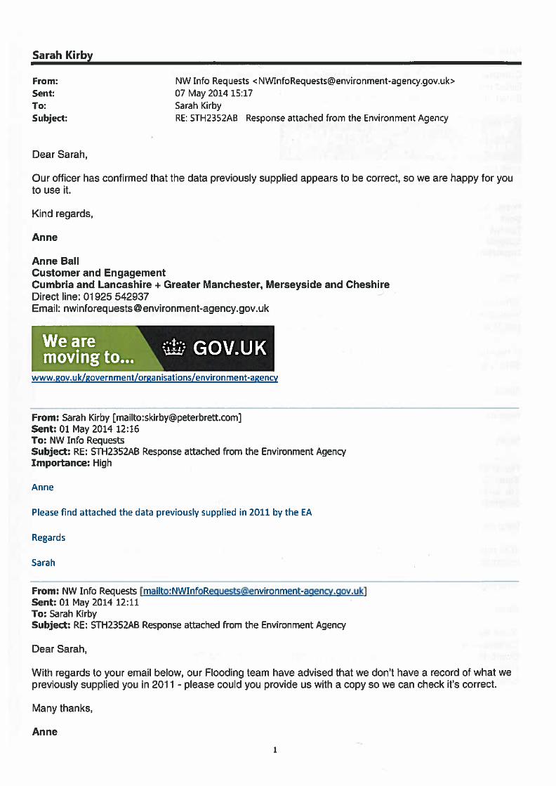
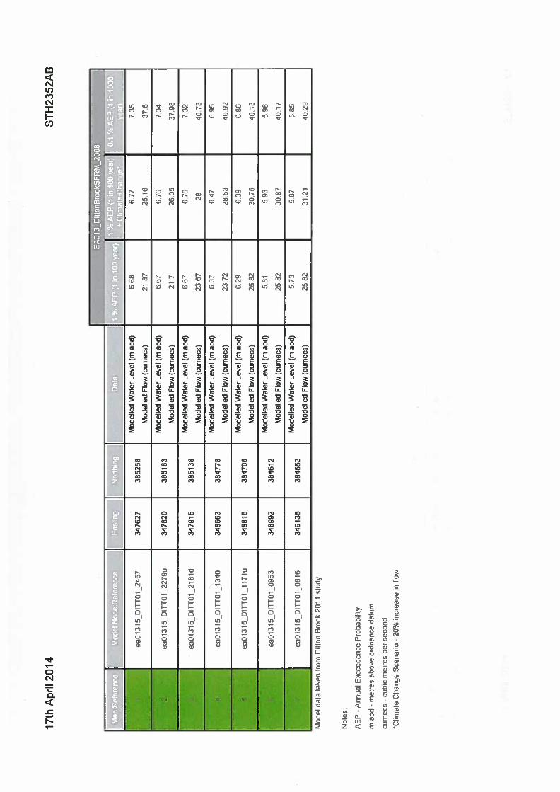
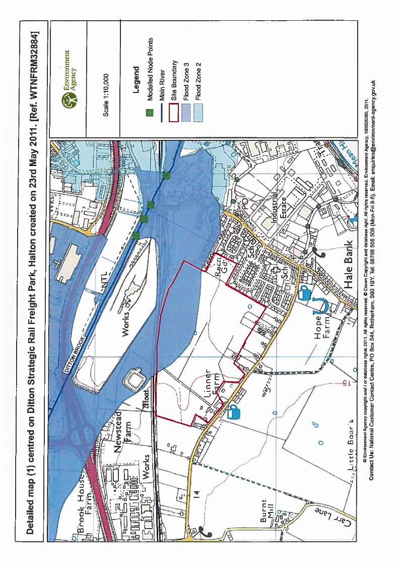
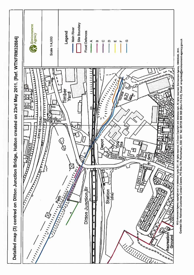
Appendix C Correspondence


Flood Risk Assessment HBC Fields, Widnes
J:\24261- HBC Fields, Widnes\24261 HBC Widnes 2014 work\Reports\2014 FRA\Project Tiger Widnes FRA 140520.docx
Appendix D RPS Drainage Design

www.rpsgroup.com
Project Tiger – ProLogis Developments Ltd HBC Fields Widnes
Drainage Design Philosophy Statement

rpsgroup.com
Document Details
Project Ref
Revision
Written by
Reviewed by
Date
16803
B
John Clayton
Lee Meadows
13 June 2011
DOCUMENT REVISIONS Revision Description Date Issued Originator
A Updated following meeting with Graham Todd, EA Offices ,Warrington 22/06/11
8/07/11 JKC
B Updated following meeting with Graham Todd, Atkins Offices, Warrington 22/09/11
RPS Sherwood House Sherwood Avenue Newark Nottinghamshire NG24 1QQ
T +44 (0) 1636 605700 F +44 (0) 1636 610696 W www.rpsgroup.com E rpsnewark [email protected]
Member of the Royal Institute of British Architects
RPS Planning & Development Ltd Centurion Court 85 Milton Park Abingdon Oxfordshire OX14 4RY Registered in England No. 02947164
Member of the Association of Consulting Engineers

rpsgroup.com
Contents
1.0 Introduction
1
2.0 Surface Water Drainage 3
3.0 Surface Water Drainage – Hydraulic Design Parameters
5
4.0 SUDs Features 6
5.0 Foul Water Drainage 7
6.0 Drainage Drawings 8
Appendices
Appendix 1 Appendix 2 Appendix 3
Windes Microdraina ge Design Calculations Proposed Link Road South of WCML Drainage Discharge Philosophy NK016803_SK0305 ‘Highway Drainage Discharge’
Appendix 4 References

rpsgroup.com
1
1.0 INTRODUCTION
This document describes the on-plot surface and foul water drainage strategy for Project Tiger, the construction of a new distribution centre and associated external car parking and lorry loading/manoeuvring areas. The site will be served by a new Highway Access – built over the existing WCML rail line to the North of the site, and a new Rail Sidings, built along the northern boundary. Both of these already have separate planning permissions. The site has an area of 31.8 hectares and is located between Hale Bank Road and the WCML Rail Line, Ordnance Grid 348250,384370, approximately 2Km to the West of Widnes. The area forms part of the plans for the ‘Merseyside Multimodal Gateway – 3MG’ and is incorporated into Halton Borough Council’s Unitary Development Plan. The majority of the site currently comprises former agricultural land, but which now forms an informal open space with a number of footpaths, and some landscaping features to the Southern and Eastern boundaries. A pond also exists along the Southern boundary – ‘Pond A’. The site generally falls towards the rail line in a North Easterly direction, with levels varying from 12.0mAOD in the SW corner to 5.0mAOD in the NE corner. The project involves the construction of a warehouse with a footprint of approximately 82,300sqm with associated offices and ancillary areas. Externally the development will comprise -
• A 800 space paved car park • A 450 space overflow car park • A concrete paved lorry hardstanding – serving an in-bound and out-bound
dock face on the warehouse, and also a concrete ramp serving the rail sidings.
• Sprinkler tanks and pump house • Gatehouse • Balancing pond – in the NW corner ‘Pond B’
The surface water drainage system serving the site will in general be designed in accordance with CIRIA publication C697 – ‘The SUDS Manual’. A substantial amount of work has already been undertaken by Atkins, Peter Brett Associates and AMEC with respect to drainage and flood risk at the HBC Fields site (see references in Appendix 2). This has been in part related to the construction of the new Highway Access forming a link to the existing A5300/A562 interchange. The Majority of the drainage from the new link road south of the WCML will discharge into Pond ‘B’ with a small portion discharging into existing Pond ‘A’ (Refer to Appendix 2 and 3). Pond ‘B’ will be built as part of the new development. Drainage from the access road to the North of the WCML will outfall to the Newstead Road Culvert and watercourse and will not be considered further in this report.

2
rpsgroup.com
2
A Flood Risk Assessment was undertaken by Peter Brett Associates in February 2007 to support a planning application for the Ditton Strategic Rail Freight Park at the HBC Fields site. Phase 1 of the work related to a landscaping contract – this comprised perimeter bunding to provide a screen for the site for the existing residential areas to the South and East. It also included the construction of pond ‘A’ – in the SE corner. A second FRA was undertaken by Amec for Halton Borough Council in January 2008 for the proposed link road.

3
rpsgroup.com
3
2.0 SURFACE WATER DRAINAGE
As noted above the topography of the site is such that the land drains towards the WCML rail embankment along the northern boundary of the site. Two culverts exist under the rail embankment – hereby referred to as the Eastern Culvert and Western Culvert. These comprise an oval brick lined culvert (1100mm wide x 1235mm high) and a 600mm diameter pipe respectively. A survey of these culverts was carried out by Atkins in April 2009, and is documented in their report – ‘HBC Fields Development and 3MG A5300 Link Road – Drainage outfalls to Ditton Brook’. It is proposed that the run off from the development is discharged to these culverts via a balancing pond. Pond ‘A’, already constructed, will take approximately 50% of the site runoff and a small portion of the new Highway Access before discharging to the Eastern Culvert. Pond ‘B’ will take the remaining site discharge, and also the majority of run-off from the new Highway Access. As noted above Pond ‘A’ has already been constructed, and Pond B will be constructed as part of the new development. Flow control devices (hydro brakes) will be fitted to the outlets on both ponds to ensure that the discharge does not exceed the current ‘Greenfield’ run-off from the site, however the determining factor in terms of controlling run off will be the adequacy of the on-site drainage network to store stormwater run-off when the outfalls (Eastern and Western culverts) to Ditton Brook are submerged during tidal/fluvial flooding. The site itself is protected from tidal (1:200) and fluvial (1:1000) flooding and this is covered in more detail in a separate Flood Risk Assessment Report by Peter Brett Associates. Drainage to the lorry yard areas will in the main comprise proprietary slot drains such as Gatic, and kerb drainage. The siphonic roof drainage system shall be split equally between Pond A (Eastern half of roof) and Pond B (Western half of roof). The site drainage will allow for controlled flooding of the lorry yard areas to a maximum depth of 300mm when considering the effects of the submerged outfalls. The various storm design scenarios are listed in section 3.0 below accounting for tidal and fluvial flooding. The tidal and fluvial flood levels have been verified by a Flood Risk Assessment undertaken in a separate report by Peter Brett Associates. The northern and western yard areas will drain to Pond ‘B’, and the Southern and Western yard areas will drain to Pond ‘A’. No flooding detrimental to buildings shall be permitted in either a tidal or fluvial flooding situation; the finished floor level will be a minimum of 600mm above any temporary flood levels within the external yard areas. No surface water run-off from paved or other impermeable surfaces shall be permitted to escape onto the surface of adjacent sites or roadways. When considering off-site flooding to areas to the north of the railway embankment – specifically Mr Gladstone’s filed at Newstead Road Embankment and at the WCML embankment on the Eastern culvert, these have been dealt with as part of the Atkins report (referenced in Appendix 2).

4
rpsgroup.com
4
In accordance with SEPA Pollution Prevention Guideline document PPG3 ‘Use and design of Oil Separators in Surface Water Drainage Systems’, all surface water drainage from the lorry parking and manoeuvring areas will pass through a Class 1 Full Retention Separator, with alarm. Car parking areas shall drain through a Class 1 by-pass separator with alarm. The separators will comply with BS EN 858 part 1 and 2 in full.
Roof drainage shall not pass through a separator, but will discharge directly to either
balancing pond A or B.

5
rpsgroup.com
5
3.0 SURFACE WATER DRAINAGE - HYDRAULIC DESIGN PARA METERS
Drainage calculations will be completed on Micro–Drainage WinDES software and parameters based on “Modified Rational Method” for simulation.
Global Variables
Rainfall: Storm intensities based on FSR methodology Design Return Period: 1, 10, 30 and 100 years. Storm Duration: 15, 30, 60, 120, 240, 360, 480, 960 and 1440 minutes M5-60: 20mm “r” Ratio: 0.420 Volumetric Runoff coefficient: 0.75 Global time of entry: 4min Infiltration: Ignore for peak flow design Backdrops : Allow in design Min pipe cover: 900mm
The following scenarios will be modelled –
o Free outfall – 1 in 1 year, 1 in 30 year and 1:100+20% year storms modelled no allowance for climate change.
No surcharging for 1 year storm, no surface flooding for a 30 year storm. For storm returns of between 1:30 and 1:100 year, flooding is to be controlled on site and limited to lorry parking areas, to a maximum depth of 300mm.
o Submerged outfall - Fluvial Flooding (1 in 100 years) – Flood Level to be
taken as constant at 6.37mAOD.
Storm events in excess of a 1 in 30 year storm – floodwater controlled within the site boundary, and flooding limited to the lorry parking areas, to a maximum depth of 300mm.
o Submerged outfall - Tidal Flooding (1 in 200 years) – Flood Level to be
taken as 7.28mAOD.
Storm events in excess of a 1 in 30 year storm – floodwater controlled within the site boundary, and flooding limited to the lorry parking areas, to a maximum depth of 300mm.
o Submerged outfall - Tidal Flooding (1 in 1 year) – Flood Level to be taken as 6.55mAOD.
Storm events in excess of a 1 in 30 year storm – floodwater controlled within the site boundary, and flooding limited to the lorry parking areas, to a maximum depth of 300mm.

6
rpsgroup.com
6
4.0 SUDS FEATURES
The site drainage shall include the following sustainable drainage features -
(I) Porous paving – will be used in the 450 space overflow car park. This will comprise porous geo-synthetic blocks with topsoil/gravel infill on a laying course and aggregate sub base with geo-membrane – a ‘Type C’ (no infiltration) system. The hydraulic design of the permeable paving will be undertaken in accordance with Chapter 12 of CIRIA Guide C697 ‘The SUDS Manual’.
(II) Attenuation Pond B – The attenuation pond will be lined and will be designed
to accommodate a 1:100 storm event on a high tide cycle with sufficient freeboard. It will collect the surface water drainage run off from 50% of the site (The existing Pond A taking the remaining area). The minimum treatment volume shall be taken as 15mm x area of drainage. The design of the attenuation pond will in general follow the recommendations of Chapter 17 of CIRIA Guide C697 ‘The SUDS Manual’.
Infiltration features are not considered suitable for the site given the ground conditions which comprise boulder clay to a depth of approximately 13m. Permeability testing has been carried out on site to confirm this.

7
rpsgroup.com
7
5.0 FOUL WATER DRAINAGE Foul Drainage from the development shall discharge to the existing United Utilities sewer in Hale Bank Road as per Option 1 of the Atkins Utility Report undertaken in 2008 (Document Reference 290.24605). United Utilities have given a Part 1 approval for this connection in their letter dated 7/08/08, based on a maximum discharge of 10l/s. The connection point will be to either manhole 6301 (IL 10.68mAOD) or manhole 8101 (IL 9.47m AOD). Historic water use data for industrial buildings supplied by ProLogis Developments based on a 24hour operation, 7 day week indicates an average consumption of 0.0078 l/s/1000sqm. Based on the size of building proposed this would give a total average consumption of 0.86l/s and a corresponding peak flow of 5.7l/s with allowance of 10% for infiltration. Reference Sewers for Adoption 6th Edition, section 2.12 a figure of 0.6l/s/hectare of developable land is recommended for the domestic foul flow discharge. Based on a developable area of 129,000 sqm (excluding car parking, landscape and balancing pond features) this would give a design discharge of 7.7l/s. Therefore the foul flows from the proposed development are not expected to exceed the maximum discharge of 10l/s

8
rpsgroup.com
8
6.0 DRAINAGE DRAWINGS
The following drawings have been prepared in accordance with the preceding drainage network design model, simulation and SUDS calculations. These drawings constitute the package of supporting drawings for the approval and construction of the underground surface and foul water network. A full list of the drawings is shown below:
• 16803_T_0302 ‘-‘ Surface and Foul Water Drainage Layout • 16803_T_0600 ‘A’ Proposed Finished Levels • 16803_T_0315 ‘-‘ Attenuation Pond ‘B’ construction details • 16803_T_0320 ‘A’ Porous Paving Details – Overflow Car Park

9
rpsgroup.com
Appendix 1 – Windes Calculations

10
rpsgroup.com
Appendix 2 – Proposed Link Road South of WCML Drain age Discharge Philosophy

11
rpsgroup.com
Appendix 3 – NK016803_SK0305 ‘Highway Drainage Disc harge’

12
rpsgroup.com
Appendix 4 – References List of References
Document Title Author Reference Date
HBC Fields, Widnes - Flood Risk Assessment Peter Brett Associates
24261/001 June 2011
Flood Risk Assessment 3MG A5300 Link Road AMEC 5788001467 Jan 2008
Related Documents