GX Pilot Series Autopilots Installation/User Manual Rev B TRUTRAK FLIGHT SYSTEMS 1500 S. Old Missouri Road Springdale, AR 72764 POSTAL SERVICE ADDRESS P.O. Box 189 Springdale, AR 72765-0189 Ph: 479-751-0250 Fax: 479-751-3397 www.trutrakap.com

Welcome message from author
This document is posted to help you gain knowledge. Please leave a comment to let me know what you think about it! Share it to your friends and learn new things together.
Transcript
GX Pilot Series Autopilots
Installation/User Manual
Rev B
TRUTRAK FLIGHT SYSTEMS
1500 S. Old Missouri Road
Springdale, AR 72764
POSTAL SERVICE ADDRESS
P.O. Box 189 Springdale, AR 72765-0189
Ph: 479-751-0250 Fax: 479-751-3397
www.trutrakap.com

INSTALLATION/USER MANUAL For
GX Pilot Series Autopilots
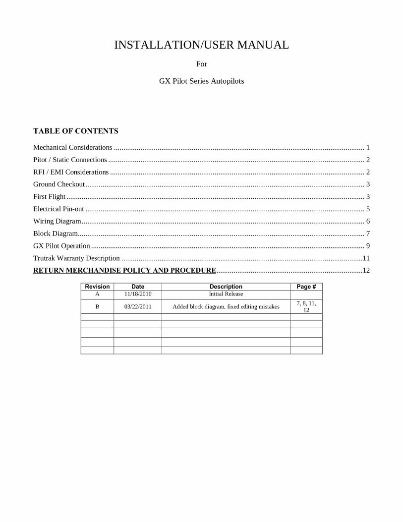
TABLE OF CONTENTS
Mechanical Considerations .................................................................................................................................... 1 Pitot / Static Connections ....................................................................................................................................... 2 RFI / EMI Considerations ...................................................................................................................................... 2 Ground Checkout ................................................................................................................................................... 3 First Flight ............................................................................................................................................................. 3 Electrical Pin-out ................................................................................................................................................... 5 Wiring Diagram ..................................................................................................................................................... 6 Block Diagram ....................................................................................................................................................... 7
GX Pilot Operation ................................................................................................................................................ 9
Trutrak Warranty Description ...............................................................................................................................11
RETURN MERCHANDISE POLICY AND PROCEDURE .............................................................................12 Revision Date Description Page #
A 11/18/2010 Initial Release B 03/22/2011 Added block diagram, fixed editing mistakes 7, 8, 11,
12
TruTrak Flight Systems 1 GX Pilot Installation/User Manual March 2011 Rev B
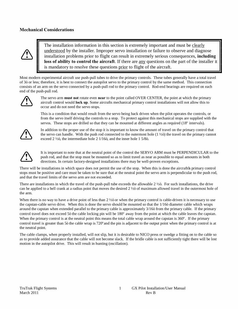
Mechanical Considerations
The installation information in this section is extremely important and must be clearly understood by the installer. Improper servo installation or failure to observe and diagnose installation problems prior to flight can result in extremely serious consequences, including loss of ability to control the aircraft. If there are any questions on the part of the installer it is mandatory to resolve these questions prior to flight of the aircraft.
Most modern experimental aircraft use push-pull tubes to drive the primary controls. These tubes generally have a total travel of 3” or less; therefore, it is best to connect the autopilot servo to the primary control by the same method. This connection consists of an arm on the servo connected by a push-pull rod to the primary control. Rod-end bearings are required on each end of the push-pull rod.
The servo arm must not rotate even near to the point called OVER CENTER, the point at which the primary aircraft control would lock up. Some aircrafts mechanical primary control installations will not allow this to occur and do not need the servo stops.
This is a condition that would result from the servo being back driven when the pilot operates the controls, or from the servo itself driving the controls to a stop. To protect against this mechanical stops are supplied with the servos. These stops are drilled so that they can be mounted at different angles as required (18° intervals).
In addition to the proper use of the stop it is important to know the amount of travel on the primary control that the servo can handle. With the push rod connected to the outermost hole (1 ½”) the travel on the primary cannot exceed 2 ½”, the intermediate hole 2 1/16”, and the inner hole 1 5/8”.
It is important to note that at the neutral point of the control the SERVO ARM must be PERPENDICULAR to the push rod, and that the stop must be mounted so as to limit travel as near as possible to equal amounts in both directions. In certain factory-designed installations there may be well-proven exceptions.
There will be installations in which space does not permit the use of the stop. When this is done the aircraft’s primary control stops must be positive and care must be taken to be sure that at the neutral point the servo arm is perpendicular to the push rod, and that the travel limits of the servo arm are not exceeded.
There are installations in which the travel of the push-pull tube exceeds the allowable 2 ½”. For such installations, the drive can be applied to a bell crank at a radius point that moves the desired 2 ½” of maximum allowed travel in the outermost hole of the arm.
When there is no way to have a drive point of less than 2 ½” or when the primary control is cable-driven it is necessary to use the capstan-cable servo drive. When this is done the servo should be mounted so that the 1/16” diameter cable which wraps around the capstan when extended parallel to the primary cable is approximately 3/16” from the primary cable. If the primary control travel does not exceed 5” the cable locking pin will be 180° away from the point at which the cable leaves the capstan. When the primary control is at the neutral point this means the total cable wrap around the capstan is 360°. If the primary control travel is greater than 5” the cable wrap is 720°and the pin is adjacent to the output point when the primary control is at the neutral point.
The cable clamps, when properly installed, will not slip, but it is desirable to NICO press or swedge a fitting on to the cable so as to provide added assurance that the cable will not become slack. If the bridle cable is not sufficiently tight there will be lost motion in the autopilot drive. This will result in hunting (oscillation).
TruTrak Flight Systems 2 GX Pilot Installation/User Manual March 2011 Rev B
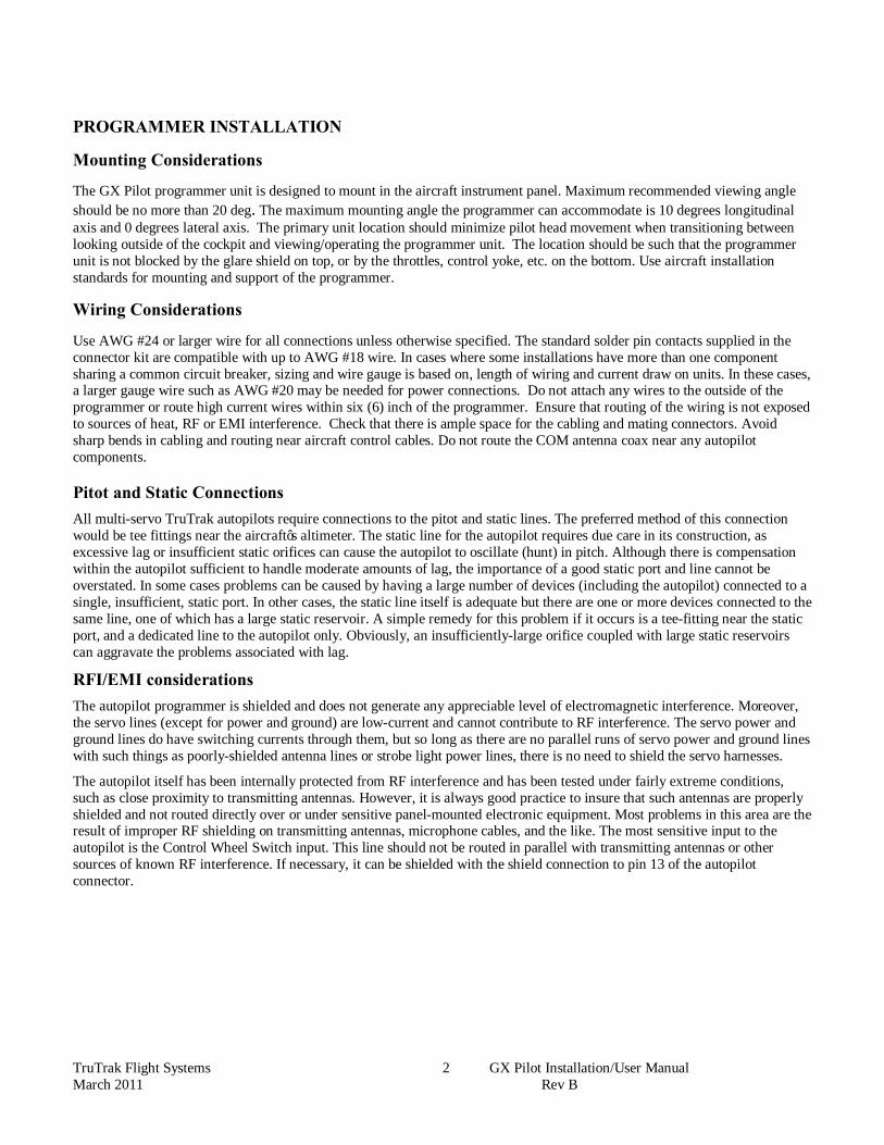
PROGRAMMER INSTALLATION
Mounting Considerations The GX Pilot programmer unit is designed to mount in the aircraft instrument panel. Maximum recommended viewing angle should be no more than 20 deg. The maximum mounting angle the programmer can accommodate is 10 degrees longitudinal axis and 0 degrees lateral axis. The primary unit location should minimize pilot head movement when transitioning between looking outside of the cockpit and viewing/operating the programmer unit. The location should be such that the programmer unit is not blocked by the glare shield on top, or by the throttles, control yoke, etc. on the bottom. Use aircraft installation standards for mounting and support of the programmer. Wiring Considerations Use AWG #24 or larger wire for all connections unless otherwise specified. The standard solder pin contacts supplied in the connector kit are compatible with up to AWG #18 wire. In cases where some installations have more than one component sharing a common circuit breaker, sizing and wire gauge is based on, length of wiring and current draw on units. In these cases, a larger gauge wire such as AWG #20 may be needed for power connections. Do not attach any wires to the outside of the programmer or route high current wires within six (6) inch of the programmer. Ensure that routing of the wiring is not exposed to sources of heat, RF or EMI interference. Check that there is ample space for the cabling and mating connectors. Avoid sharp bends in cabling and routing near aircraft control cables. Do not route the COM antenna coax near any autopilot components. Pitot and Static Connections All multi-servo TruTrak autopilots require connections to the pitot and static lines. The preferred method of this connection would be tee fittings near the aircraft’s altimeter. The static line for the autopilot requires due care in its construction, as excessive lag or insufficient static orifices can cause the autopilot to oscillate (hunt) in pitch. Although there is compensation within the autopilot sufficient to handle moderate amounts of lag, the importance of a good static port and line cannot be overstated. In some cases problems can be caused by having a large number of devices (including the autopilot) connected to a single, insufficient, static port. In other cases, the static line itself is adequate but there are one or more devices connected to the same line, one of which has a large static reservoir. A simple remedy for this problem if it occurs is a tee-fitting near the static port, and a dedicated line to the autopilot only. Obviously, an insufficiently-large orifice coupled with large static reservoirs can aggravate the problems associated with lag.
RFI/EMI considerations The autopilot programmer is shielded and does not generate any appreciable level of electromagnetic interference. Moreover, the servo lines (except for power and ground) are low-current and cannot contribute to RF interference. The servo power and ground lines do have switching currents through them, but so long as there are no parallel runs of servo power and ground lines with such things as poorly-shielded antenna lines or strobe light power lines, there is no need to shield the servo harnesses.
The autopilot itself has been internally protected from RF interference and has been tested under fairly extreme conditions, such as close proximity to transmitting antennas. However, it is always good practice to insure that such antennas are properly shielded and not routed directly over or under sensitive panel-mounted electronic equipment. Most problems in this area are the result of improper RF shielding on transmitting antennas, microphone cables, and the like. The most sensitive input to the autopilot is the Control Wheel Switch input. This line should not be routed in parallel with transmitting antennas or other sources of known RF interference. If necessary, it can be shielded with the shield connection to pin 13 of the autopilot connector.
TruTrak Flight Systems 3 GX Pilot Installation/User Manual March 2011 Rev B
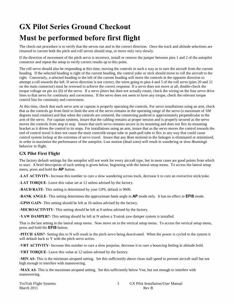
GX Pilot Series Ground Checkout Must be performed before first flight The check-out procedure is to verify that the servos run and in the correct direction. Once the track and altitude selections are returned to current both the pitch and roll servos should stop, or move only very slowly.
If the direction of movement of the pitch servo is incorrect, install or remove the jumper between pins 1 and 2 of the autopilot connector and repeat the setup to verify correct results up to this point.
The roll servo should also be responding at this time, moving the controls in such a way as to turn the aircraft from the current heading. If the selected heading is right of the current heading, the control yoke or stick should move to roll the aircraft to the right. Conversely, a selected heading to the left of the current heading will move the controls in the opposite direction to attempt a roll towards the left. If servo direction is not correct, the wires going to pins 4 and 5 of the roll servo (pins 20 and 21 on the main connector) must be reversed to achieve the correct response. If a servo does not move at all, double-check the torque voltage on pin six (6) of the servo. If a servo jitters but does not actually rotate, check the wiring on the four servo drive lines to that servo for continuity and correctness. If the servo does not seem to have any torque, check the relevant torque control line for continuity and correctness.
At this time, check that each servo arm or capstan is properly operating the controls. For servo installations using an arm, check that as the controls go from limit to limit the arm of the servo remains in the operating range of the servo (a maximum of 100 degrees total rotation) and that when the controls are centered, the connecting pushrod is approximately perpendicular to the arm of the servo. For capstan systems, insure that the cabling remains at proper tension and is properly secured as the servo moves the controls from stop to stop. Insure that each servo remains secure in its mounting and does not flex its mounting bracket as it drives the control to its stops. For installations using an arm, insure that as the servo moves the control towards the end of control travel it does not cause the main control’s torque tube or push-pull tube to flex in any way that could cause control system lockup at the extremes of servo travel. Insure that any “lost motion” in the linkages is eliminated or minimized, in order to maximize the performance of the autopilot. Lost motion (dead zone) will result in wandering or slow “hunting” behavior in flight.
GX Pilot First Flight The factory default settings for the autopilot will not work for every aircraft type, but in most cases are good points from which to start. A brief description of each setting is given below, beginning with the lateral setup menu. To access the lateral setup menu, press and hold the AP button.
-LAT ACTIVITY- Increase this number to cure a slow wandering across track, decrease it to cure an overactive stick/yoke.
-LAT TORQUE- Leave this value set at 12 unless advised by the factory.
-BAUD RATE- This setting is determined by your GPS, default is 9600.
-BANK ANGLE- This setting determines the approximate bank angle in AP mode only. It has no effect in EFIS mode.
-GPSS GAIN- This setting should be left at 16 unless advised by the factory.
-MICROACTIVITY- This setting should be left at 0 unless advised by the factory.
-YAW DAMPER?- This setting should be left at N unless a Trutrak yaw damper system is installed.
That is the last setting in the lateral setup menu. Now move on to the vertical setup menu. To access the vertical setup menu, press and hold the EFIS button.
-PITCH AXIS?- Setting this to N will result in the pitch servo being deactivated. When the power is cycled to the system it will default back to Y with the pitch servo active.
-VRT ACTIVITY- Increase this number to cure a slow porpoise, decrease it to cure a bouncing feeling in altitude hold.
-VRT TORQUE- Leave this value at 12 unless advised by the factory.
-MIN AS- This is the minimum airspeed setting. Set this sufficiently above clean stall speed to prevent aircraft stall but not high enough to interfere with maneuvering.
-MAX AS- This is the maximum airspeed setting. Set this sufficiently below Vne, but not enough to interfere with maneuvering.

TruTrak Flight Systems 4 GX Pilot Installation/User Manual March 2011 Rev B
-STATIC LAG- This should be left at 0 unless advised by the factory.
-MICROACTIVITY- This should be left at 0 unless advised by the factory.
-HALF STEP?- This should be left at N unless advised by the factory.
The first flight should be done after having completed all the setup and testing on the ground. Insure that the servos have sufficient torque to properly fly the aircraft as they are installed. The autopilot should be able to handle considerable turbulence. It is best to test the autopilot in its basic mode first. Engage it in the AP mode first before using it coupled to the G3X system. This will insure you are able to tune the settings to correctly fly your aircraft before introducing another variable.
TruTrak Flight Systems 5 GX Pilot Installation/User Manual March 2011 Rev B
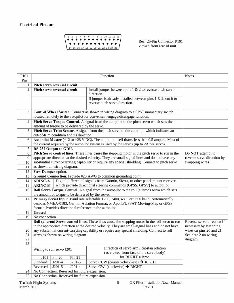
Electrical Pin-out
P101 Pin
Function Notes
1 Pitch servo reversal circuit 2 Pitch servo reversal circuit Install jumper between pins 1 & 2 to reverse pitch servo
direction.
If jumper is already installed between pins 1 & 2, cut it to reverse pitch servo direction.
3 Control Wheel Switch. Connect as shown in wiring diagram to a SPST momentary switch
located remotely to the autopilot for convenient engage/disengage function.
4 Pitch Servo Torque Control. A signal from the autopilot to the pitch servo which sets the amount of torque to be delivered by the servo.
5 Pitch Servo Trim Sensor. A signal from the pitch servo to the autopilot which indicates an out-of-trim condition and its direction.
6 Autopilot Master (+12 to +28 V DC). The autopilot itself draws less than 0.5 ampere. Most of the current required by the autopilot system is used by the servos (up to 2A per servo).
7 RS-232 Output to GDU. 8 Pitch Servo control lines. These lines cause the stepping motor in the pitch servo to run in the
appropriate direction at the desired velocity. They are small-signal lines and do not have any substantial current-carrying capability or require any special shielding. Connect to pitch servo as shown on wiring diagram.
Do NOT attempt to reverse servo direction by swapping wires
9 10 11 12 Yaw Damper option. 13 Ground Connection. Provide #20 AWG to common grounding point. 14 ARINC-A Digital differential signals from Garmin, Sierra, or other panel-mount receiver
which provide directional steering commands (GPSS, GPSV) to autopilot
15 ARINC-B 16 Roll Servo Torque Control. A signal from the autopilot to the roll (aileron) servo which sets
the amount of torque to be delivered by the servo.
17 Primary Serial Input. Baud rate selectable 1200, 2400, 4800 or 9600 baud. Automatically decodes NMEA-0183, Garmin Aviation Format, or Apollo/UPSAT Moving-Map or GPSS format. Provides directional reference to the autopilot.
18 Unused 19 No connection
20 21 22 23
Roll (aileron) Servo control lines. These lines cause the stepping motor in the roll servo to run in the appropriate direction at the desired velocity. They are small-signal lines and do not have any substantial current-carrying capability or require any special shielding. Connect to roll servo as shown on wiring diagram.
Reverse servo direction if necessary by swapping wires on pins 20 and 21. See note 2 on wiring diagram.
Wiring to roll servo J201 Direction of servo arm / capstan rotation (as viewed from face of the servo body)
for RIGHT aileron
J101 Pin 20 Pin 21 Standard J201-4 J201-5 Servo CCW (counter-clockwise) è RIGHT Reversed J201-5 J201-4 Servo CW (clockwise) è RIGHT
24 No Connection. Reserved for future expansion. 25 No Connection. Reserved for future expansion.
Rear 25-Pin Connector P101 viewed from rear of unit
1
20 21 22 23 24 25
2 3 4 5 6 7 8 9 10 11 12 13
14 15 16 17 18 19
TruTrak Flight Systems 6 GX Pilot Installation/User Manual March 2011 Rev B
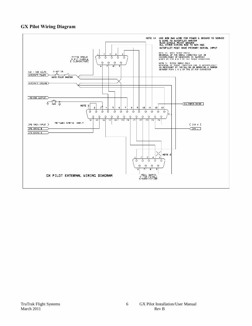
GX Pilot Wiring Diagram
TruTrak Flight Systems 7 GX Pilot Installation/User Manual March 2011 Rev B
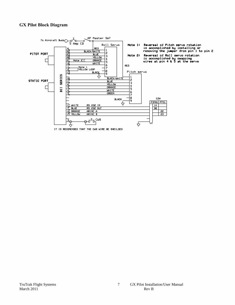
GX Pilot Block Diagram

TruTrak Flight Systems 8 GX Pilot Installation/User Manual March 2011 Rev B
TruTrak Flight Systems 9 GX Pilot Installation/User Manual March 2011 Rev B
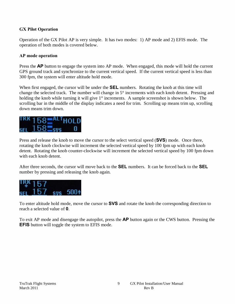
GX Pilot Operation Operation of the GX Pilot AP is very simple. It has two modes: 1) AP mode and 2) EFIS mode. The operation of both modes is covered below. AP mode operation Press the AP button to engage the system into AP mode. When engaged, this mode will hold the current GPS ground track and synchronize to the current vertical speed. If the current vertical speed is less than 300 fpm, the system will enter altitude hold mode. When first engaged, the cursor will be under the SEL numbers. Rotating the knob at this time will change the selected track. The number will change in 5° increments with each knob detent. Pressing and holding the knob while turning it will give 1° increments. A sample screenshot is shown below. The scrolling bar in the middle of the display indicates a need for trim. Scrolling up means trim up, scrolling down means trim down.
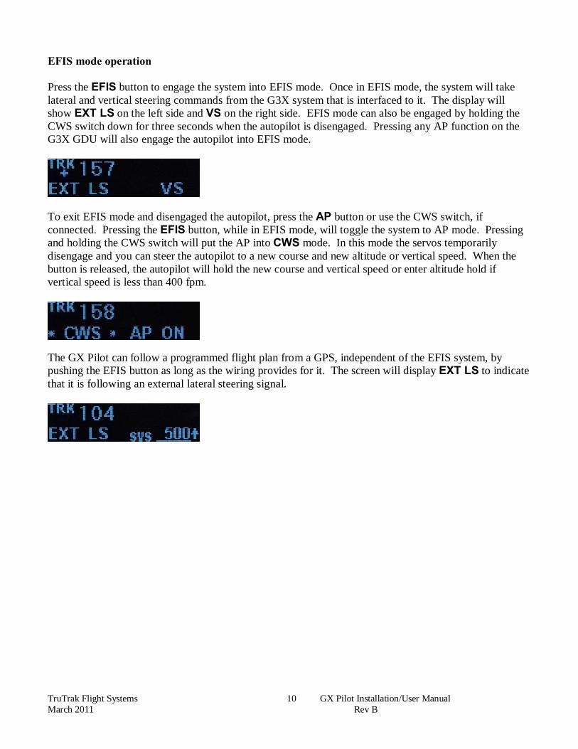
Press and release the knob to move the cursor to the select vertical speed (SVS) mode. Once there, rotating the knob clockwise will increment the selected vertical speed by 100 fpm up with each knob detent. Rotating the knob counter-clockwise will increment the selected vertical speed by 100 fpm down with each knob detent. After three seconds, the cursor will move back to the SEL numbers. It can be forced back to the SEL number by pressing and releasing the knob again.
To enter altitude hold mode, move the cursor to SVS and rotate the knob the corresponding direction to reach a selected value of 0. To exit AP mode and disengage the autopilot, press the AP button again or the CWS button. Pressing the EFIS button will toggle the system to EFIS mode.
TruTrak Flight Systems 10 GX Pilot Installation/User Manual March 2011 Rev B
EFIS mode operation Press the EFIS button to engage the system into EFIS mode. Once in EFIS mode, the system will take lateral and vertical steering commands from the G3X system that is interfaced to it. The display will show EXT LS on the left side and VS on the right side. EFIS mode can also be engaged by holding the CWS switch down for three seconds when the autopilot is disengaged. Pressing any AP function on the G3X GDU will also engage the autopilot into EFIS mode.
To exit EFIS mode and disengaged the autopilot, press the AP button or use the CWS switch, if connected. Pressing the EFIS button, while in EFIS mode, will toggle the system to AP mode. Pressing and holding the CWS switch will put the AP into CWS mode. In this mode the servos temporarily disengage and you can steer the autopilot to a new course and new altitude or vertical speed. When the button is released, the autopilot will hold the new course and vertical speed or enter altitude hold if vertical speed is less than 400 fpm.
The GX Pilot can follow a programmed flight plan from a GPS, independent of the EFIS system, by pushing the EFIS button as long as the wiring provides for it. The screen will display EXT LS to indicate that it is following an external lateral steering signal.

TruTrak Flight Systems 11 GX Pilot Installation/User Manual March 2011 Rev B
Warranty On TruTrak Flight Systems Products We at TruTrak Flight Systems know how important it is to feel as though the customer is purchasing a product that the manufacturer is going to stand behind. For this reason we want offer more than the basic one year warranty that is standard to this industry. The warranty on all TruTrak products will be three years from the date of purchase. Abuse and misuse of a product are not covered under this warranty. Modification to a product may void the warranty, as well as carry a penalty when upgrading to another product. This three year warranty will be for all products except the Pictorial Turn & Bank, which will continue to have a warranty of one year from the date of purchase.
TruTrak Flight Systems 12 GX Pilot Installation/User Manual March 2011 Rev B
RETURN MERCHANDISE POLICY AND PROCEDURE Under no circumstances should products be returned to TruTrak without first obtaining a Return of Merchandise Authorization number (RMA #) from TruTrak. An RMA# may be obtained by contacting us at 866-878-8725. Products that do not have an RMA # will not be processed. Please include documentation stating the reason for the return and describing any symptoms, failure modes, suspected causes of damage, diagnostics performed, data collected, etc. Product(s) should be packaged in their original shipping containers. In lieu of this, they should be very carefully packaged in containers suitable to protect them during transit. For your protection, items should be insured for the full value. Note that damage caused during shipping will not be repaired under warranty. The outside of the box must be clearly marked with the RMA # issued by TruTrak and the RMA # must also be noted on the return documents. Products will be returned to the customer at no charge via FedEx Ground or UPS Ground. If customer requests expedited shipping (2nd Day or Overnight) they will be charged the shipping cost and must supply a credit card number. INTERNATIONAL SHIPMENTS: Trutrak sends all International shipments with an insurance value on all products. Trutrak pays for shipping only. The customer is responsible for any and all additional fees, duties, taxes associated with the shipment. When sending products to Trutrak for repair or otherwise please be advised that the customer is responsible for all charges and fees associated with shipment. For your protection, items should be insured for the full value. Trutrak states on all product returns “WARRANTY REPAIR AT NO CHARGE TO CUSTOMER. A COMMERCIAL INVOICE VALUE OF $___ GIVEN FOR INSURANCE PURPOSES ONLY”
Please keep in mind that your government or another entity in your country may impose a charge for custom and/or brokerage fees, duties and taxes on items received from the US. These charges do not originate from our company nor do we benefit from them in any way. You are responsible for payment of all custom and brokerage fees, duties and taxes that may be imposed when these goods are imported into your country.
Send UPS/FedEx/DHL return shipments to:
Trutrak Flight Systems, Inc., 1500 South Old Missouri Road, Springdale, AR 72764 USA Attention: Returns Dept. RMA# ______________
TRUTRAK FLIGHT SYSTEMS
1500 S. Old Missouri Road
Springdale, AR 72764
POSTAL SERVICE ADDRESS
P.O. Box 189 Springdale, AR 72765-0189
Ph: 479-751-0250 Fax: 479-751-3397
Toll free: 866-TRUTRAK
866-(878-8725)
www.trutrakap.com
Related Documents