Gutor PxW AC UPS System PEW 5 – 200 kVA single phase; PDW 10 – 220 kVA three phase Higher ratings on request

Welcome message from author
This document is posted to help you gain knowledge. Please leave a comment to let me know what you think about it! Share it to your friends and learn new things together.
Transcript
Gutor PxW AC UPS SystemPEW 5 – 200 kVA single phase; PDW 10 – 220 kVA three phaseHigher ratings on request
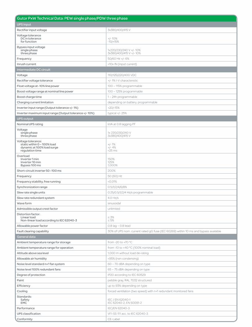
Gutor PxW Technical Data: PEW single phase/PDW three phaseUPS InputRectifier input voltage 3x380/400/415 V
Voltage toleranceDC in tolerancefor function
+/- 10%-10/+15%
Bypass input voltage single phasethree phase
1x220/230/240 V +/- 10%3x380/400/415 V +/- 10%
Frequency 50/60 Hz +/- 6%
Inrush current <10x IN (input current)
Intermediate DC circuitVoltage 110/125/220/400 VDC
Rectifier voltage tolerance +/- 1% I-V characteristic
Float voltage at -10% line power 100 – 115% programmable
Boost voltage range at nominal line power 100 – 125% programmable
Boost charge time 1 – 24h programmable
Charging current limitation depending on battery, programmable
Inverter input range (Output tolerance +/- 1%) +20/-15%
Inverter maximum input range (Output tolerance +/- 10%) typical +/- 25%
UPS outputNominal UPS rating kVA at 0.8 lagging PF
Voltage single phase three phase
1x 220/230/240 V3x380/400/415 V
Voltage tolerance:static within 0 – 100% loaddynamic at 100% load surgeregulation time
+/- 1%+/- 4%<25 ms
OverloadInverter 1 minInverter 10 minBypass 100 ms
150%125%1,000%
Short-circuit inverter 50 –100 ms 200%
Frequency 50 (60) Hz
Frequency stability, free running <0.01%
Synchronization range 0.5/1/2/4/6/8%
Slew rate single units 0.25/0.5/1/2/4 Hz/s programmable
Slew rate redundant system 4.0 Hz/s
Wave form sinusoidal
Admissible output crest factor unlimited
Distortion factor:Linear loadNon-linear load according to IEC 62040-3
≤ 3%≤ 5%
Allowable power factor 0.8 lag – 0.8 lead
Fault clearing capability 30% of UPS nom. current rated gG fuse (IEC 60269) within 10 ms and bypass available
General dataAmbient temperature range for storage from -20 to +70 °C
Ambient temperature range for operation from -10 to +40 °C (100% nominal load)
Altitude above sea level 1,000 m without load de-rating
Allowable air humidity <95% (non condensing)
Noise level standard n+1 fan system 60 – 70 dBA depending on type
Noise level 100% redundant fans 65 – 75 dBA depending on type
Degree of protection IP20 according to IEC 60529
Paint pebble gray, RAL 7032 structured
Efficiency up to 93% depending on type
Cooling forced ventilation (two speed) with n+1 redundant monitored fans
Standards:SafetyEMC
IEC / EN 62040-1IEC 62040-2, EN 50091-2
Performance IEC/EN 62040-3
UPS classification VFI-SS-111 acc. to IEC 62040-3
Conformity CE-Label
Gutor™ PxW Specifications: PEW single phase/PDW three phase
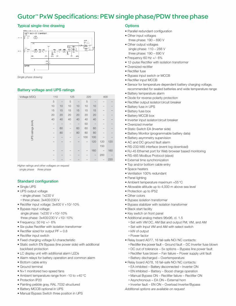
Voltage (VDC) 110 125 220 400
UP
S r
atin
gs (k
VA
)
5 – 5 – 5 – – –
10 10 10 10 10 10 – –
15 15 15 15 15 15 – –
20 20 20 20 20 20 – –
40 40 40 40 40 40 – –
– – – – 50 – – –
– 60 – 60 60 60 – –
– 80 – 80 80 80 – –
– – – – 100 100 – –
– – – – – 120 120 120
150
– – – – – 160 – 160
– – – – – – 200 –
– – – – – – – 220
Standard configuration• Single UPS• UPS output voltage
º single phase: 1x230 V
º three phase: 3x400/230 V• Rectifier input voltage: 3x400 V +10/-10%• Bypass input voltage
single phase: 1x230 V +10/-10%three phase: 3x400/230 V +10/-10%
• Frequency: 50 Hz +/- 6%• Six-pulse Rectifier with isolation transformer• Rectifier sized for output PF = 0.8• Rectifier input switch• Fixed charging voltage IU characteristic• Static switch EN Bypass (line power side) with additional
backfeed protection• LC display unit with additional alarm LEDs• Alarm relays for battery operation and common alarm• Bottom cable entry• Ground terminal• N+1 monitored two-speed fans• Ambient temperature range from -10 to +40 °C• Protection IP20• Painting pebble gray, RAL 7032 structured • Battery MCCB optional in UPS• Manual Bypass Switch three position in UPS
Typical single-line drawing
Battery voltage and UPS ratings
Single phase drawing
Higher ratings and other voltages on request■ single phase three phase
Options• Parallel redundant configuration• Other input voltages
three phase: 190 – 690 V• Other output voltages
single phase: 110 – 288 Vthree phase: 190 – 690 V
• Frequency 60 Hz +/- 6%• 12-pulse Rectifier with isolation transformer• Oversized rectifier• Rectifier fuse• Bypass input switch or MCCB• Rectifier input MCCB• Sensor for temperature dependent battery charging voltage,
recommended for sealed batteries and wide temperature range• Battery temperature alarm• Diode for reverse polarity protection• Rectifier output isolator/circuit breaker• Battery fuse in UPS• Battery fuse box• Battery MCCB box• Inverter input isolator/circuit breaker• Oversized inverter• Static Switch EA (Inverter side)• Battery Monitor (programmable battery data)• Battery asymmetry supervision• AC and DC ground fault alarm• RS-232/485 interface (event log download)• RJ-45 Ethernet port for Web browser based monitoring• RS-485 Modbus Protocol (slave)• External time synchronization• Top and/or bottom cable entry• Space heaters• Ventilation 100% redundant• Panel lighting• Ambient temperature maximum +55 °C• Allowable altitude up to 4,000 m above sea level• Protection up to IP52• Other colors• Bypass isolation transformer• Bypass stabilizer with isolation transformer• Black start facility• Key switch on front panel• Additional analog meters 96x96, cl. 1.5
º Set with VM DC, AM Bat and output FM, VM, and AM
º Set with Input VM and AM with select switch
º kW of output
º Power factor• Relay board A077, 16 fail-safe NO / NC contacts:
º Rectifier line power fault – Ground fault – DC Inverter fuse blown
º DC out of tolerance – 5x options – Bypass line power fault
º Rectifier fuse blown – Fan failure – Power supply unit fault
º Battery discharged – Overtemperature• Relay board A078, 16 fail-safe NO / NC contacts:
º EA inhibited – Battery disconnected – Inverter ON
º EN inhibited – Battery – Boost charge operation
º Manual Bypass ON – Rectifier failure – Rectifier ON
º Asynchronous – EA ON – External horn
º Inverter fault – EN ON – Overload Inverter/BypassAdditional options are available on request

Human-machine interface (front panel)
The front panel includes a comprehensive and flexible human-machine interface. It is divided into four sections:
1 The system panel shows the system’s current state of operation (i.e., which part of the system is currently supplying the load and which is in stand-by mode). LEDs also indicate possible faults.
2 Use the operations panel to turn the system on and off. The lamp-test button indicates whether all LED indication lights are functioning properly. To shut down the system, you have to press the ON and OFF buttons at the same time.
3 Flexibly assign LEDs to indicate system alarms and external signals.
4 On the alarm-indication panel, the respective LEDs light up to indicate a possible fault, or that an alarm has occurred.
Operational parameters• Selectable second display language• Bypass operation• Boost charge• Auto boost (charge)• Battery-capacity test• Battery-monitor test (optional)• Set date/time
Measurements• Load in percentage of nominal kVA rating• AC rectifier line power 1 voltage and current• AC bypass line power 2 voltage• DC total current, battery voltage and current• Battery temperature (with optional sensor)• AC Inverter current• AC output voltage, current and frequency• AC output peak current• Time left in battery operation with current load (optional with programmed
battery data)• Event log with date and time (operating mode changes and alarms)
Gutor North America:12121 Wickchester Lane Suite 400, Houston, Texas 77079, USAP +888-994-8867 | F +281-588-2199 | [email protected]
Headquarters:Gutor Electronic LLC, Hardstrasse 72 – 74, 5430 Wettingen, SwitzerlandP +41 (0)56 437 34 34 | F +41 (0)56 437 34 44 | [email protected]
Malaysia production facilities:Gutor Electronic Asia Pacific Sdn.Bhd No.19, Jalan Juruukur U1/19, Seksyen U1, Hicom Glenmarie Ind Park, 40150 Shah Alam, Selangor Malaysia
www.gutor.com
1 2
3
4
©2014 Schneider Electric. All Rights Reserved. Schneider Electric and Gutor are trademarks owned by Schneider Electric Industries SAS or its affiliated companies. All other trademarks are the property of their respective owners. • 998-1218613_GMA-US
Related Documents