FORM NO. 3319-945 The TORO COMPANY - 1998 GROUNDSMASTERr 580-D MODEL NO. 30581 - 80001 & UP OPERATOR’S MANUAL (TRACTION AND CUTTING UNITS) To understand this product, and for safety and optimum performance, read this manual before starting the engine. Pay special attention to SAFETY INSTRUCTIONS highlighted by this symbol. It means CAUTION, WARNING or DANGER - personal safety instruction. Failure to comply with the instruction may result in personal injury. The GROUNDSMASTER 580-D meets or exceeds the American National Standards Institute’s safety standards for riding mowers; thus TORO proudly displays the ANSI safety seal.

Welcome message from author
This document is posted to help you gain knowledge. Please leave a comment to let me know what you think about it! Share it to your friends and learn new things together.
Transcript
FORM NO. 3319-945
The TORO COMPANY - 1998
GROUNDSMASTER� 580-D
MODEL NO. 30581 - 80001 & UPOPERATOR'S
MANUAL
(TRACTION AND CUTTING UNITS)
To understand this product, and for safety and
optimum performance, read this manual before
starting the engine. Pay special attention to SAFETY
INSTRUCTIONS highlighted by this symbol.
It means CAUTION, WARNING or DANGER -
personal safety instruction. Failure to comply with
the instruction may result in personal injury.
The GROUNDSMASTER 580-D meets or exceeds
the American National Standards Institute's safety
standards for riding mowers; thus TORO proudly
displays the ANSI safety seal.

2
FOREWORD
The Groundsmaster� 580-D was developed to satisfy the demand for a large scale rotary mower that combines
the productivity of a 16-foot mowing machine with the handling ease of a trim mower. The Groundsmaster 580-D
has advanced concepts in engineering and design, and if properly maintained, will provide excellent service.
Since the Groundsmaster 580-D is a high quality product, TORO is concerned about its future use and safety of the
user. Therefore, anyone involved with the product, including the operator, should read and understand this manual.
Major sections are:
- Safety Instructions
- Specifications
- Before Operating
- Controls
- Operating Instructions
- Maintenance
This manual emphasizes safety, mechanical and general product information. DANGER, WARNING and CAUTION
identify safety messages. Whenever the triangular safety alert symbol appears, understand the safety message
that follows. For complete safety instructions, read pages 3 - 7. IMPORTANT highlights special mechanical
information and NOTE emphasizes general product information worthy of special attention.
Diesel engine exhaust and some of itsconstituents are known to the State of
California to cause cancer, birth defects,or other reproductive harm.
SPARK ARRESTERIn some places a spark arrester muffler must be used because of local, state or federal regulations. Since the engine
on the Groundsmaster 580-D is fitted with a turbo-charger as standard equipment, it meets the spark arrestor
standards of the United States Department of Agriculture, the United States Forestry and Section 4442, Public
Resources Code of the State of California.
This product is equipped with a diesel engine certified by the manufacturer to meet EPA regulations for Nonroad
Diesel Engine Emission Standards in affect at the time of manufacture.
SERVlCE MANUALThe Groundsmaster� 580-D Service Manual contains information for troubleshooting, testing and repair of thehydraulic system, brakes and cutting units for the Groundsmaster� 580-D. To order this publication, contact yourlocal authorized Toro Distributor. Ask for Form 90-743-SL, Groundsmaster� 580-D Service Manual.
MITSUBISHI S4S-DT DIESEL ENGINE MANUAL ORDERING INFORMATION:
IN THE U.S.:Contact Mitsubishi Engine North America TechnicalPublications Department. 610 Supreme DriveBensenville, IL. 60106
OUTSIDE THE U.S.:Contact your local Mitsubishi Engine Distributor (orYour Authorized Toro Distributor).
Whenever you have questions or need service, contact your local authorized Toro Distributor. In addition to having a
complete line of accessories and professional turf care service technicians, the distributor has a complete line of
genuine TORO replacement parts to keep your machine operating properly. Keep your TORO all TORO. Buy
genuine TORO parts and accessories.

3
TABLE OF CONTENTSSAFETY INSTRUCTIONS 3-4. . . . . . . . . . . . . . . . . . .
SAFETY AND INSTRUCTION DECALS 5-7. . . . . .
SPECIFICATIONS 8-9. . . . . . . . . . . . . . . . . . . . . . . . .
LOOSE PARTS 10. . . . . . . . . . . . . . . . . . . . . . . . . . . . . .
BEFORE OPERATING 11-14. . . . . . . . . . . . . . . . . . .
CONTROLS 15-17. . . . . . . . . . . . . . . . . . . . . . . . . . . . .
OPERATING INSTRUCTIONS 18-25. . . . . . . . . . . . .
LUBRICATION 25-26. . . . . . . . . . . . . . . . . . . . . . . . . .
DAILY MAINTENANCE CHECKLIST 27. . . . . . . . . . .
MAINTENANCE 28-42. . . . . . . . . . . . . . . . . . . . . . . . .
Engine Oil and Filter 28. . . . . . . . . . . . . . . . . . . . . .
Engine Fuel System 29. . . . . . . . . . . . . . . . . . . . . . .
Engine Cooling System 30. . . . . . . . . . . . . . . . . . .
Air Cleaner Maintenance 31. . . . . . . . . . . . . . . . . .
Hydraulic System Service 32. . . . . . . . . . . . . . . . . .
Planetary Gear Drive Service 33. . . . . . . . . . . . . . .
Battery Service 34. . . . . . . . . . . . . . . . . . . . . . . . . . .
Fuses and Circuit Breaker 35. . . . . . . . . . . . . . . . .
Brake System Service 35. . . . . . . . . . . . . . . . . . . . .
Wheels and Tires 35. . . . . . . . . . . . . . . . . . . . . . . . .
Cutting Unit Lubrication 36. . . . . . . . . . . . . . . . . . .
Blade Maintenance 36. . . . . . . . . . . . . . . . . . . . . . .
Blade Bolt Torque 37. . . . . . . . . . . . . . . . . . . . . . . . .
Removing Cutting Unit Blades 37. . . . . . . . . . . . .
Inspecting and Sharpening Blade 37. . . . . . . . . .
Adjusting Cutting Unit Belt Tension 38. . . . . . . .
Replacing Blade Drive Belts 39. . . . . . . . . . . . . . . .
Separating Cutting Units from Traction Unit 39. .
Checking and Correcting Cutting Unit Blade
Mismatch 40. . . . . . . . . . . . . . . . . . . . . . . . . . . . . . . .
Adjusting Winglet Stabilizers 41. . . . . . . . . . . . . . .
Traction Control Neutral Adjustment 41. . . . . . . .
Traction (Neutral) Switch Adjustment 41. . . . . . . .
Traction Control Rod Adjustment 42. . . . . . . . . . .
Cylinder Head Bolts 42. . . . . . . . . . . . . . . . . . . . . . .
Engine Valve Clearance 42. . . . . . . . . . . . . . . . . . .
ELECTRICAL SCHEMATICS 43-44. . . . . . . . . . . . . .
HYDRAULIC SCHEMATIC 45. . . . . . . . . . . . . . . . . . . .
MAINTENANCE SCHEDULE 46. . . . . . . . . . . . . . . . . .
PRODUCT IDENTIFICATION 47. . . . . . . . . . . . . . . . .
THE TORO PROMISE Back Cover. . . . . . . . . . . . . . . .
SAFETY INSTRUCTIONS
Improper use or maintenance by the operator or owner
of the machine can result in injury. Reduce the potential
for any injury by complying with the following safety
instructions.
BEFORE OPERATING1. Read and understand the contents of this manual
before operating the machine. To get replacement
manuals, send complete model and serial number to:
The Toro Company
8111 Lyndale Avenue South
Bloomington, MN 55420-1196.
2. Never allow children to operate the machine or
adults to operate it without proper instruction.
3. Become familiar with the controls and know how to
stop the machine and engine quickly.
4. Keep all shields, safety devices and decals in
place. If a shield, safety device or decal is
malfunctioning, illegible or damaged, repair or replace
it before operating the machine.
5. Always wear substantial shoes. Do not operate
machine while wearing sandals, tennis shoes,
sneakers or when barefoot. Do not wear loose fitting
clothing that could get caught in moving parts and
possibly cause personal injury.
6. Wearing safety glasses, safety shoes, long pants
and a helmet is advisable and required by some local
ordinances and insurance regulations.
7. Make sure the work area is clear of objects which
might be picked up and thrown by the cutter blades.
8. Do not carry passengers on the machine. Keepeveryone, especially children and pets, away from theareas of operation.9. Since diesel fuel is highly flammable, handle itcarefully:
A. Use an approved fuel container.
B. Do not remove fuel tank cap while engine is hotor running.
C. Do not smoke while handling fuel.
D. Fill fuel tank outdoors and only to within an
inch (25 mm) from the top of the tank, not the fillerneck. Do not overfill.
E. Wipe up any spilled fuel.
10. Be sure interlock switches are adjusted correctlyso engine cannot be started unless traction pedal is
released - neutral position - and PTO switch is inNEUTRAL position.
WHILE OPERATING11. Check interlock switches daily for properoperation. If a switch malfunctions, replace or adjust itbefore operating the machine. The interlock system isfor your protection, so do not bypass it. Replace allinterlock switches every two years.
12. Do not run engine in a confined area withoutadequate ventilation. Exhaust is hazardous and couldbe deadly.13. Sit on the seat when starting and operating themachine.
14. Before starting the engine each day, test warninglamps and signal lights to assure proper operation.

4
SAFETY INSTRUCTIONS15. Pay attention when using the machine. To preventloss of control:
A. Mow only in daylight or when there is goodartificial light.
B. Watch for holes or other hidden hazards.
C. Be extremely careful when operating close tosand traps, ditches, creeks, steep hillsides or otherhazards.
D. Reduce speed when making sharp turns.Avoid sudden stops and starts.
E. Look to the rear to assure no one is behind the
machine before backing up.
F. Watch for traffic when near or crossing roads.Always yield the right-of-way.
G. Reduce speed when driving downhill.
16. Keep hands, feet and clothing away from movingparts and the cutting units.
17. This product may exceed noise levels of 85 dB(A)at the operator position. Ear protectors arerecommended, for prolonged exposure, to reduce thepotential of permanent hearing damage.18. Do not touch engine, turbo-charger, radiator,
muffler or exhaust pipe while engine is running or soonafter it is stopped. These areas could be hot enough tocause burns.19. Before getting off the seat:
A. Move traction pedal to neutral.
B. Set parking brake.
C. Disengage cutting units and wait for blades tostop.
D. Stop engine and remove key from switch.
E. Do not park on slopes unless wheels arechocked or blocked.
20. If a cutting blade strikes a solid object or vibratesabnormally, stop immediately, turn engine off, setparking brake and wait for all motion to stop. Inspectfor damage. Repair or replace any damaged partsbefore operating.
MAINTENANCE
21. Before servicing or making adjustments, stopengine and remove key from the switch.
22. Assure entire machine is properly maintained andin good operating condition. Frequently check all nuts,bolts and screws.
23. Frequently check all hydraulic line connectors andfittings. Assure all hydraulic hoses and lines are in
good condition before applying pressure to the
system.24. If the Groundsmaster 580-D loses power and
needs to be moved, either by-pass the hydraulicpump or unlock the front wheel hubs. Unlocking the
front wheels disables the machine braking system.
Block the wheels before unlocking the hubs to keepthe machine from moving. To tow the machine,
connect to the towing vehicle with a rigid towing
device. Do not use chains, cables or other non-rigiddevices for towing. Lock the hubs when towing is
completed.25. Keep body and hands away from pin hole leaks or
nozzles that eject high pressure hydraulic fluid. Use
cardboard or paper to find hydraulic leaks. Hydraulicfluid escaping under pressure can penetrate skin and
cause injury. Fluid accidentally injected into the skin
must be surgically removed within a few hours by adoctor or gangrene may occur.
26. Before any hydraulic system maintenance, stopengine and lower cutting units to the ground so all
pressure is relieved.
27. For major repairs or other assistance, contact yourlocal Toro Distributor.
28. To reduce potential fire hazard, keep engine area
free of excessive grease, grass, leaves and dirt.29. If engine must be running to perform maintenance
or an adjustment, keep hands, feet, clothing and otherparts of the body away from cutting units and other
moving parts. Keep everyone away.
30. Do not overspeed the engine by changinggovernor setting. Maximum engine speed is 2750 rpm.
To assure safety and accuracy, have an Authorized
Toro Distributor check maximum engine speed.31. Shut engine off before checking or adding oil to the
crankcase.
32. Disconnect battery before servicing the machine.If battery voltage is required for troubleshooting or test
procedures, temporarily connect the battery.33. For optimum performance and safety, use genuine
Toro replacement parts and accessories.
Replacement parts and accessories made by othermanufacturers could be dangerous and may void the
product warranty of The Toro Company.

5
SAFETY AND INSTRUCTION DECALSThe following decals are installed on the machine. If any become damaged or illegible, replace it. The decal partnumber is listed below and in your parts catalog. Replacement decals can be ordered from your Authorized ToroDistributor.
UNDER LOWER CONTROL COVER(Part No. 98-1487)ON REAR FENDER AND FRONT FRAME
(Part No. 72-4080)
ON RIGHT SIDE OF SEAT(Part No. 80-4890)
UNDER LOWER CONTROL COVER(Part No. 95-0831)
ON CUTTING UNITS, UNDER COVERS(Part No. 67-5360)
ON REAR FENDER AND FRONT FRAME(Part No. 93-9371)
Replaces Decal Part No.72-4080 for CE
ON CUTTING UNITS, UNDER COVERS(Part No. 93-7273)
Replaces Decal Part No. 67-5360 for CE
ON FENDER ALONGSIDE HYDRAULIC TANK(Part No. 95-0821)
ON FAN SHROUD(Part No. 76-8750)

6
SAFETY AND INSTRUCTION DECALS
ON FLOOR, FORWARDOF TRACTION PEDAL
(Part No. 69-0940)
ON DECK, UNDER COVER(Part No. 95-0833)
ON FENDER ALONGSIDE FUEL TANK
(Part No. 95-0822) ON LEFT REAR OF CUTTING UNIT(Part No. 95-0817)
ON BOTH WHEEL HUBS(Part No. 72-4070)
ON LOWER CONTROL PANEL(Part No. 98-3040)
ON FRONT OF CUTTING UNITS(Part No. 43-8480)
ON FLOOR, FORWARDOF TRACTION PEDAL
(Part No. 95-0823)Replaces Decal Part No.
69-0940 for CE
ON FRONT OF CUTTING UNITS(Part No. 93-7815)
Replaces Decal Part No. 43-8480 for CE
ON BOTH WHEEL HUBS(Part No. 95-0829)
Replaces Decal Part No.72-4070 for CE

7
SAFETY AND INSTRUCTION DECALS
ON FRONT AND REAR CUTTINGUNITS MOTOR MOUNT PLATES
(Part No. 95-0845)
RIGHT SIDE NEAR TEST PORTS(Part No. 95-0824)
ON CUTTING UNITS(Part No. 66-1340)
ON CENTER CONTROL PANEL(Part No. 95-0815)
ON STEERING COLUMN SUPPORT(Part No. 95-0825)
ON DECK, UNDER COVER(Part No. 95-0819) ON DECK, UNDER COVER
(Part No. 95-0820)
ON CUTTING UNIT CASTOR ARMS(Part No. 95-0818)
RIGHT SIDE NEAR TEST PORTS(Part No. 93-7824)
Replaces Decal Part No.66-1340 for CE
RIGHT SIDE NEAR TEST PORTS(Part No. 98-4387)

8
SPECIFICATIONSTRACTION UNIT
Engine: Mitsubishi, Model S4S-DT 4 cycle, fourcylinder, over-head valve, 203.3 cu. in. (3331 cc)displacement, water cooled diesel. Rated 80 hp @2750 rpm. 17:1 compression ratio, direct injected andturbo-charged. Crankcase capacity: 10.6 qt (10 l)
w/filter.
Air Cleaner: Heavy duty, centrifugal air type
w/replaceable element.
Cooling System: Radiator w/wide-spaced fins
(5 per in.). Variable speed fan controlled by enginetemperature. Full flow hydraulic oil cooler (7 fins/in.).Coolant capacity 3.9 gal (14.7 l) of 50/50 mixture ofethylene glycol and water.
Fuel System: Fuel tank capacity: 28 gal (106 l) of No. 2diesel fuel.
Electrical: 12 volt automotive type system. Dualmaintenance free batteries w/1300 Amp cold cranking
power at 0� F (18� C). 50 Amp alternator with integralregulator.
Controls: Individual deck lift levers, High Range/LowRange ground speed selector, PTO and ignitionswitches. Hand throttle, ON/OFF cruise control switchand cruise engage button. Single implement shut-off,steering tower and wheel tilt lever and service brake
pedal. Foot operated traction pedal and steering brakepedals with parking brake latch.
Warning Systems: Indicator lights and audible signalswarn of:Low engine oil pressure.High water temperature.No charge.Water in fuel.
Low hydraulic oil level.High hydraulic oil temperature.Air cleaner clogged.Hydraulic oil filter needs service.
Indicator lights alone indicate:
Parking brake on.Cruise control is engaged.
Groundsmaster 580-D is in High Range groundspeed mode.
Interlock System: Prevents engine starting if tractionpedal is out of neutral. Stops engine if operator eitherleaves seat or parking brake on with traction pedal outof neutral. Prevents PTO engagement if operator is outof seat, engine is off, or all cutting units are raised.
Prevents engagement of High Range ground speedmode if a cutting unit is lowered, front cutting unit is notfully raised or if engine is shut off.
Steering: 15-1/2 in. (39 cm) patented tilt steeringwheel and tower, released and locked by single controllever. Dual hydraulic cylinder power steering for extrasharp turning.
Seat and Storage: Deluxe seat w/armrests, backrestand suspension. Adjustable fore and aft travel, weightand height. Tool storage tray under hinged floor plate;storage and beverage holder alongside control panel.
Brakes: Enclosed, multiple front hydraulic disc brakesoperated by right foot pedal. Mechanical steeringbrakes via two pedals which lock together for parkingbrake function. Dynamic braking through closed-loophydrostatic drive.
Tires/Wheels:Front - two 31 x 12.50-15, 8-ply high floatation turf tires w/tubes.
Rear - two 23 x 10.50-12, 6 ply tubeless turf tire.
Ground Speed: Infinitely variable.Forward Speeds - Low; 0-7.5 mph (12.1 km/h).
High; 0-20 mph (32.2 km/h).Reverse Speeds - Low; 0-3 mph (4.8 km/h). High; 0-8 mph (12.9 km/h).
Ground Clearance: 8 in. (20.3 cm).
Hydraulic Oil System and Reservoir: 40 gal (151 l)total system capacity. Reservoir capacity: 32 gal(121 l). Replaceable spin-on 5 micron filter element.
Traction System: Hydrostatic closed loop systemdriving gear reduction wheel drives. Has bypass valvefor towing. Adjustable foot pedal with speed stop
controls forward/reverse ground speed. Switchengaged cruise control, disengaged by service brakeor ON/OFF switch. Cruise speed changeable withoutdisengagement.
Machine Fluid Recommendations:
Engine Oil: API Service Classification CD (see BeforeOperating or Lubrication section for oil graderecommendations).Diesel Fuel: ASTM No. 2-D
Cooling System: 50/50 mix; Water & Ethylene GlycolHydraulic Oil (Recommended brands):
Mobil 15 MMobil DTE 26Shell Tellus 68
Amoco Rykon Oil #68Conoco Super Hydraulic Oil 68Exxon Nuto H 68Kendall Kenoil R & O AW 68Pennzoil Penreco 68Phillips Magnus A 68
Standard Energol HLP 68Sun Sunvis 831 WRUnion Unax AW 68
Note: All are interchangeable.
IMPORTANT: Use only hydraulic oils specified.
Other fluids could cause system damage.
Note: A red dye additive for the hydraulic system oil is
available in 2/3 oz (20 ml) bottles. One bottle issufficient for 4-6 gal (15-23 l) of hydraulic oil. OrderPart No. 44-2500 from your Authorized ToroDistributor.

9
SPECIFICATIONSCUTTING UNITS
Cutting Unit Drive System: All hydraulic drive. Initialcutting drive engagement via electric switch. Driveshuts off or engages individually as cutting units areraised or lowered.
Automatic Weight Transfer: Patented automaticweight transfer from decks to traction unit underdemanding traction situations for improved tractionand deck floatation.
Cutting Unit Configuration: A 92 in. (234 cm) Triflexfront center cutting unit and two 57 in. (145 cm)outboard cutting units.
Mowing Rate/Width: Mows up to 14-1/2 acres/hr (5.9hectares at 7.5 mph (12.1 km/hr) using all cutting units
(assumes no overlap and stops).
Total cutting width: 192 in. (488 cm).
Height-of-Cut Range:
Low - 1-4 in. (2.5-10.2 cm).
High - 2-1/2 - 5-1/2 in. (6.3-14 cm).
Blades: Interchangeable heat treated steel blades, 20in. (50.8 cm) long, 1/4 in.(6.3 mm) thick and 2-1/2 in.(6.3 cm) wide. 5 blades on Triflex and 3 each on
outboard units.
Anti-scalp Devices: Cutting units equipped withadjustable skids. Anti-scalp cup on each bladeassembly.
TRIFLEX CUTTING UNIT (FRONT)
Type: Triflex front mounted rotary cutting unit with 5blade spindles and 92 in. (234 cm) width of cut.
Trimming Ability: Trims to either side. 8 in. (20.3 cm)cutting unit offset from outside of wheel to trim side offront cutting unit on either side.
Height-of-Cut Adjustment: 1/2 in. (12.7 mm)
increments by spacers on front castor shafts and clevispins on rear wheel forks.
Cutter Drive: Hydraulic gear motor. "BB" hex sectionbelt to center cutting unit spindles, "B" section belt towings. Splined shafts, each in two greaseable, tapered
roller bearings in cast iron housings (greaseable fromthe top). Self tensioning and permanently lubricatedbelt idlers.
Castor Wheels: Two 10.50 x 3.50 and two 12 x 5.00heavy duty, pneumatic castor wheels.
OUTBOARD CUTTING UNITS
Type: Two, three spindle, side mounted rotary cuttingunits each with a 57 in. (145 cm) width of cut.
Trimming Ability: Trims to either side. 58 in. (147cm)cutting unit offset from outside of wheel to trim side of
side cutting unit on either side.
Height-of-Cut Adjustment: 1/2 in. (12.7 mm)increments by spacers on all castor shafts.
Cutter Drive: Hydraulic gear motor. Three "B" sectionbelts to spindles
Castor Wheels: Four 10.50 x 3.50 heavy duty,
interchangeable, pneumatic castor wheels.
Cutting Unit Suspension: Outboard cutting unit armspivot from center, sweep cutting units forward in mowand lift, and rotate cutting units down and back intransport. Arms have rubber mount design for shockabsorption and more cutting unit floatation (patented).
Adjustable, spring-loaded, breakaway arms releaseand rotate outboard cutting unit upon accidentalimpact. Automatically reset when cutting unit is raised.Cam lock links automatically secure outboard cuttingunits in transport position.
Machine Width (Approx.): Transport - 7 ft,11 in. (241 cm).Mow - 16 ft, 3 in.(495 cm).
Machine Height (Approx.):
Transport - 7 ft, 7 in. (231 cm) - to top of raised cuttingunits.
Mow - 4 ft,11 in.(152 cm) - to top of seat back.
Machine Overall Length (Approx.): 14 ft(427 cm).
Total Weight (with fluids) [Approx.]: 6540 lb(2967 kg).
Accessories:
2-Post Roll Over Protection SystemCanopy optionCanopy w/ windshield optionCab with Roll Over Protection SystemRoad Light Package8 ft (244 cm) Rotary Broom
Air Conditioning7 Foot Snow blowerLeaf MulcherCold Start KitFoam Filled Castor TiresExtra Traction Drive Tire
Specifications and design subject to change without notice.

10
LOOSE PARTSNote: Use this chart as a checklist to ensure all parts have been shipped.
DESCRIPTION QTY. USE
Deck Tilt Link 1 To secure front cutting unit in vertical position for service. (Shipped in tool box)
Klik Pin 2 Used with Deck Tilt Link. (Shipped installed)
Operator's Manual 2 Read and understand before operating machine.
Parts Catalog 1
Registration Card 1 Fill Out and Return to Toro.(Shipped in tool box)

11
BEFORE OPERATING
CAUTION
Wear safety goggles and rubber gloves
when working with batteries. Charge bat�
teries in a well-ventilated place so gases
produced while charging can dissipate.
Since the gases are explosive, keep elec�
trical spark and open flame away from
batteries. Do not smoke. Nausea may
result if the gases are inhaled. Unplug
charger from electrical outlet before con�
necting to or disconnecting charger leads
from battery posts.
CHECK BATTERIES (Initial preparation)
1. Unlatch the hood and left hand engine side panel(Fig. 1). Raise and prop hood open and remove the leftside panel. Make sure hood prop is secured in one ofthe mounting brackets on hood.
Figure 11. Engine Hood2. Left Side Panel
3. Hood Latches4. Side PanelLatch
2. Remove the capscrews securing the battery tray
and slide the tray out (Fig. 2).
3. Check both batteries for charge with a hydrometer.If batteries check acceptably, slide tray back in place,secure with capscrews and lockwashers and installside panel. If batteries require charging, proceed tostep 4.
4. Remove negative (-) battery cables from batteries(Fig. 2). Connect a 3 to 4 Amp battery charger to theposts. Charge the batteries at a rate of 3 to 4 Amperesfor 4 to 8 hours.
5. When batteries are fully charged, disconnectcharger from electrical outlet and battery posts.
6. Install negative (-) cable ends, slide tray back inplace, secure with capscrews and install side panel.
Figure 21. Battery Tray2. Tray Mounting Holes3. Negative (-) Connections
4. Positive (+) Connections5. Battery Tray Mounting Screws
CHECK ENGINE OIL (DAILY)
The engine is shipped with 10.6 qt(10.0 l) of oil in thecrankcase. However, check level of oil before and afterthe engine is first started.
1. Be sure machine is positioned on a level surface.
2. Unlatch hood and raise and prop it open (Fig. 1).Make sure hood prop is secured in one of the mountingbrackets on hood.
3. Remove dipstick, wipe with a clean rag (Fig. 3) and
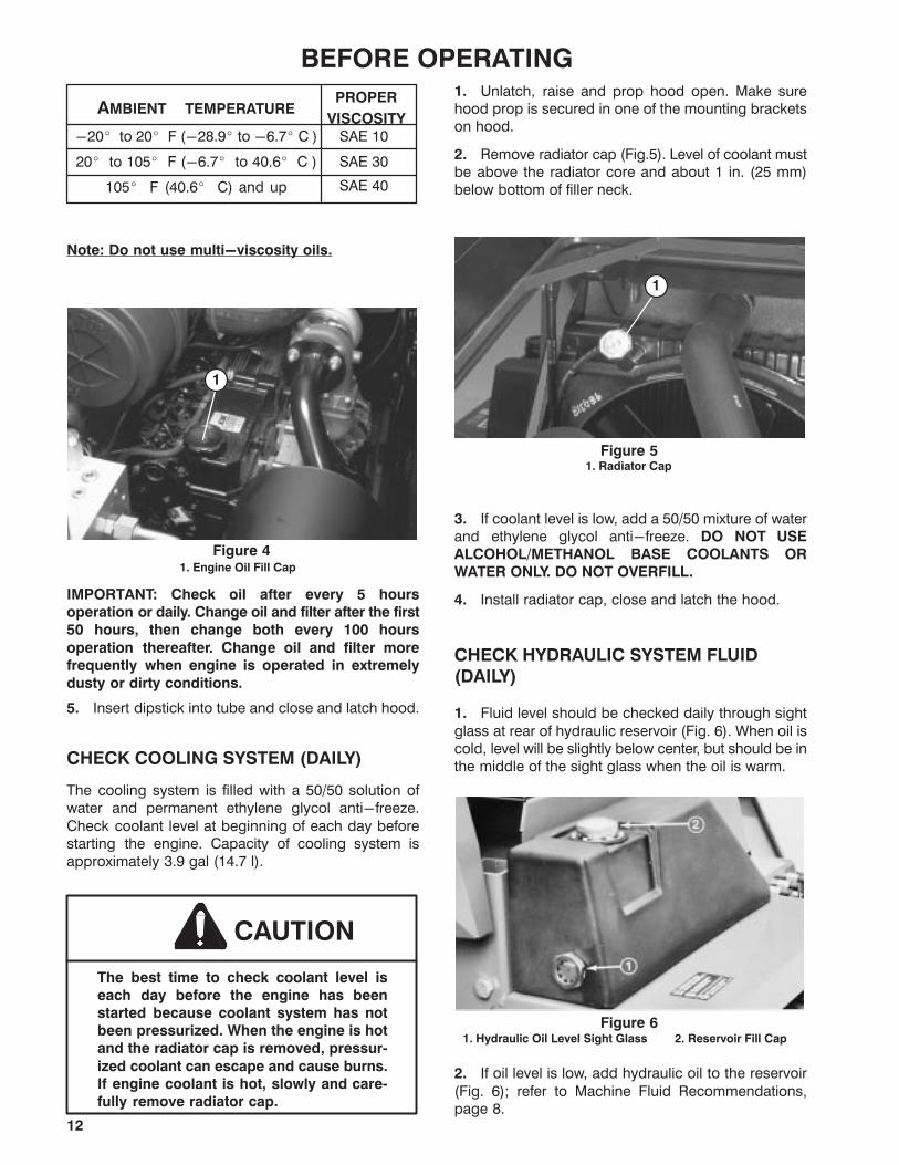
insert into tube until fully seated. Remove dipstick fromtube and check oil level. If oil level is low, remove fillercap (Fig. 4). Add oil until level is to top notch ondipstick. DO NOT OVERFILL.
Figure 31. Dipstick
1
4. The engine uses any high quality detergent oilhaving the American Petroleum Institute - API -�service classification" CD. Oil viscosityrecommendations are:
12
BEFORE OPERATING
AMBIENT TEMPERATUREPROPER
VISCOSITY
-20� to 20� F (-28.9� to -6.7� C )
105� F (40.6� C) and up
20� to 105� F (-6.7� to 40.6� C )
SAE 30
SAE 40
SAE 10
Note: Do not use multi-viscosity oils.
Figure 41. Engine Oil Fill Cap
1
IMPORTANT: Check oil after every 5 hours
operation or daily. Change oil and filter after the first
50 hours, then change both every 100 hours
operation thereafter. Change oil and filter more
frequently when engine is operated in extremely
dusty or dirty conditions.
5. Insert dipstick into tube and close and latch hood.
CHECK COOLING SYSTEM (DAILY)
The cooling system is filled with a 50/50 solution ofwater and permanent ethylene glycol anti-freeze.
Check coolant level at beginning of each day beforestarting the engine. Capacity of cooling system isapproximately 3.9 gal (14.7 l).
CAUTION
The best time to check coolant level is
each day before the engine has been
started because coolant system has not
been pressurized. When the engine is hot
and the radiator cap is removed, pressur�
ized coolant can escape and cause burns.
If engine coolant is hot, slowly and care�
fully remove radiator cap.
1. Unlatch, raise and prop hood open. Make surehood prop is secured in one of the mounting bracketson hood.
2. Remove radiator cap (Fig.5). Level of coolant mustbe above the radiator core and about 1 in. (25 mm)below bottom of filler neck.
Figure 51. Radiator Cap
1
3. If coolant level is low, add a 50/50 mixture of waterand ethylene glycol anti-freeze. DO NOT USE
ALCOHOL/METHANOL BASE COOLANTS OR
WATER ONLY. DO NOT OVERFILL.
4. Install radiator cap, close and latch the hood.
CHECK HYDRAULIC SYSTEM FLUID
(DAILY)
1. Fluid level should be checked daily through sight
glass at rear of hydraulic reservoir (Fig. 6). When oil iscold, level will be slightly below center, but should be inthe middle of the sight glass when the oil is warm.
Figure 61. Hydraulic Oil Level Sight Glass 2. Reservoir Fill Cap
2. If oil level is low, add hydraulic oil to the reservoir
(Fig. 6); refer to Machine Fluid Recommendations,page 8.

13
BEFORE OPERATINGFILL FUEL TANK
CAUTION
Because diesel fuel is flammable, use
caution when storing or handling it. Do not
smoke while filling the fuel tank. Do not fill
the tank while engine is running, hot, or
when machine is in an enclosed area.
Always fill fuel tank outside and wipe up
spilled fuel before starting the engine.
Store fuel in a clean, safety approved
container and keep cap in place. Use
diesel fuel for the engine only; not for any
other purpose.
1. Remove fuel tank cap (Fig. 7).
2. Fill tank to about one inch (25 mm) below bottomof filler neck with No. 2 diesel fuel. Install cap.
Figure 71. Fuel Tank Cap
CHECK TIRE PRESSURE (DAILY)
Since the Groundsmaster 580-D can be operatedunder many different types of turf conditions, propertire pressure is very important. Use the following as aguide:
Under Normal mowing conditions and when usedon a wide variety of turf grasses - 15 psi (103.4kPa) front; 13 psi (89.6 kPa) rear. 50 psi (344.7 kPa)castors.
When turf is wet and softer than normal - use lowpressure: 12 psi (82.7 kPa) front and 9 psi (62 kPa)rear.
When turf is dry and harder than normal, use
higher tire pressure: 18 psi (124 kPa) front andrear.
IMPORTANT: Do not operate in HIGH RANGE for
extended periods when tire pressure is less than 18
psi because tires may be damaged. When tire
pressure exceeds 18 psi, HIGH RANGE may be
used.
CHECK SYSTEMS OPERATION (DAILY)
Start engine. Move the Groundsmaster 580-D, slowly,to an area where the machine can be checked for
proper function. Check operation of controls, safetyinterlock system, engine, hydraulic system, brakesand cutting units. Refer to Know Your Controls andOperating Instructions sections for proper procedures.
CHECKING CUTTING UNIT MISMATCH
To assure all cutting units are at the sameheight-of-cut:
1. Adjust all cutting units to the highestheight-of-cut. Position all castor arm height-of-cutspacers to on the underside of the castor arms. Do notmove washers. Leave them in their original position.
Note: Unless all castor wheel axles are not in the samelocation, axles do not have to be relocated. All,however must be in the same holes (Fig.8).
2. Place a flat 4'x8' sheet of 3/4" plywood on a levelsurface and lower a cutting unit onto the plywood.
3. Taking each cutting blade in turn, position blade soit faces fore and aft. Measure from plywood to front tipof cutter blade and record dimension. All blade heightson same deck should be within 1/4" (6.3 mm) of oneanother. If blade heights meet criteria, proceed to
step 5. If blade heights are not within 1/4" (6.3 mm),proceed to step 4.
4. To match cutting blade height, transfer washersfrom one side of a castor wheel arm to the other. If endis to be lowered, transfer one or both washers from the
underside to the top. By contrast, if end is to be raised,transfer washer(s) from the top to the underside. Eachwasher is 1/8" (3 mm) thick. Repeat measurement ofblade tip height and record new dimensions.
5. Repeat steps 2-3 on remaining cutting units, and
step 4, if necessary. If washers are transferred on aoutboard cutting unit castor arm, be sure to transfer thesame number on both ends of the castor arm.
6. Compare blade height dimensions of all cuttingunits. Blade heights must be within 3/8" (9.5 mm) of
one another. If they are not, determine which cuttingunit height can be changed to compensate fordifference and either transfer washers from bottom totop to lower unit, or from top to bottom to raise. Transferan equal number of washers at all castor wheel
locations to keep cutting unit level - two on front unit,four on outboard units.

14
BEFORE OPERATINGADJUSTING HEIGHT-OF-CUT
The height-of-cut is adjustable from 1 to 5-1/2 in.(25to 140 mm) in 1/2 in.(13 mm) increments. Positioningthe castor wheel axles in the top holes of the castor
forks (Fig. 8) allows Low range height-of-cut settingsfrom 1 to 4 in. (25 to 102 mm); positioning the castorwheel axles in the lower holes of the castor forks (Fig. 8)allows High range height-of-cut settings from 2-1/2to 5-1/2 in. (63.5 to 140 mm).
Figure 8
1. Start engine, position the machine on a level
surface, lower cutting units to a point where castorwheels can be removed from arms, set lift levers inneutral, set parking brake and shut engine off. Removeignition key to prevent accidental startup.
2. Position castor wheel axles on all cutting units inthe same hole in the castor forks.
3. On the front cutting unit, remove the hairpin cotterand clevis pins from the rear castor pivot arms (Fig. 9).Align the pivot arm holes with selected height-of-cutbracket holes in the deck frames, insert clevis pins andinstall the hairpin cotters (Fig. 9).
Figure 91. Hairpin Cotter2. Clevis Pin
3. Castor Axle mount holes4. Pivot Arm
4. On all remaining castor wheel assemblies, removelynch pin from castor fork shafts (Fig. 10). Removecastor fork shaft and spacer assembly from the castorarm (Fig. 10). Place spacers onto castor spindle todesired height-of-cut setting and install castor fork
shaft in arm (Fig. 9). Install remaining spacers ontoshaft and secure assemblies with the lynch pin(Fig.10).
Figure 101. Lynch Pin2. Spacers
3. Washers
ADJUSTING SKIDS
After initial set up or if height-of-cut is changed, deck
skids should also be adjusted. Adjust skids byloosening flange lock nuts (Fig. 11), positioning skid atspecified height (see chart) and re-tightening flangelock nuts.
Front Cutting Unit
All H.O.C.-3/8" to 1/2" above level surface
Outboard Cutting Units
1" H.O.C.-Skid positioned all the way up
1-1/2" to 3" H.O.C.- Skid positioned 1/2" to 1"above level surface.
3" and above H.O.C.- Skid positioned all the waydown,
Figure 111. Skid
15
CONTROLSSeat (Fig. 12) - Pull seat adjusting lever (right side)outward,slide seat fore or aft to desired position andrelease lever to lock seat in position. Seat moves 5.9in.(15 cm) fore and aft in 19/32 in. (15 mm) increments.Knob at lower center provides infinitely variable weight
adjustment from 110 - 285 lb (49.9 - 129.3 kg).
Figure 121. Seat Adjusting Lever2. Weight Adjusting Knob
3. Weight Indicator
Seat height adjusts vertically to three positions. Toraise: lift seat to first or second click stop; to lower: liftseat to highest position, then lower to lowest position.
Arm rests pivot up and down.
Warning Light Check Switch (Fig. 13) - Beforebeginning operation, press switch button. All lights oncontrol panel should light. If a light fails to illuminate,there is an electrical malfunction requiring immediaterepair.
Engine Oil Pressure Warning (Fig. 13) -Dangerously low engine oil pressure is indicated byboth a warning indicator light and audible signal. Whenthis occurs, stop the engine immediately to keeppossible engine damage minimal.
No Charge Warning (Fig. 13) - No charge to the
batteries is indicated by a warning indicator light andaudible signal.
Fuel System Warning (Fig. 13) - A warning indicatorlight and audible signal warn of water in the fuel andneed for service.
Coolant Temperature Warning (Fig. 13) - If enginecoolant temperature exceeds 215� F (101.7� C), a
warning indicator light illuminates and audible signalsounds. If coolant temperature exceeds 230� F (110�C), the engine automatically shuts down. Switch resetsautomatically when system and engine cools down.
Hour Meter (Fig. 13) - Registers accumulated hoursof engine operation. Useful for determining intervals for
service maintenance and lubrication.
Coolant Temperature Gauge (Fig. 13) - Indicatestemperature of system coolant.
Fuel Gauge (Fig. 13) - Indicates quantity of fuel in fueltank.
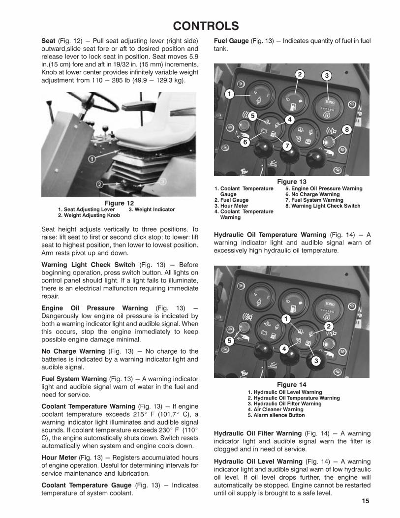
Figure 135. Engine Oil Pressure Warning6. No Charge Warning7. Fuel System Warning8. Warning Light Check Switch
1. Coolant Temperature Gauge2. Fuel Gauge3. Hour Meter4. Coolant Temperature Warning
1
2 3
45
67
8
Hydraulic Oil Temperature Warning (Fig. 14) - Awarning indicator light and audible signal warn ofexcessively high hydraulic oil temperature.
Figure 141. Hydraulic Oil Level Warning2. Hydraulic Oil Temperature Warning3. Hydraulic Oil Filter Warning4. Air Cleaner Warning5. Alarm silence Button
12
3
4
5
Hydraulic Oil Filter Warning (Fig. 14) - A warningindicator light and audible signal warn the filter isclogged and in need of service.
Hydraulic Oil Level Warning (Fig. 14) - A warningindicator light and audible signal warn of low hydraulic
oil level. If oil level drops further, the engine willautomatically be stopped. Engine cannot be restarteduntil oil supply is brought to a safe level.
16
CONTROLSAir Cleaner Warning (Fig. 14) - A warning indicatorlight and audible signal warn of a clogged air cleanerrequiring service. These warnings alert that the enginehas been operated in excess of when normal filtermaintenance should have occurred.
Alarm Silence Button (Fig. 14) - Pressing buttonsilences alarm. Alarm system will disengage and
automatically reset when problem is corrected.
Parking Brake Indicator (Fig. 15) - On steeringcolumn. Alerts operator the parking brake is on.
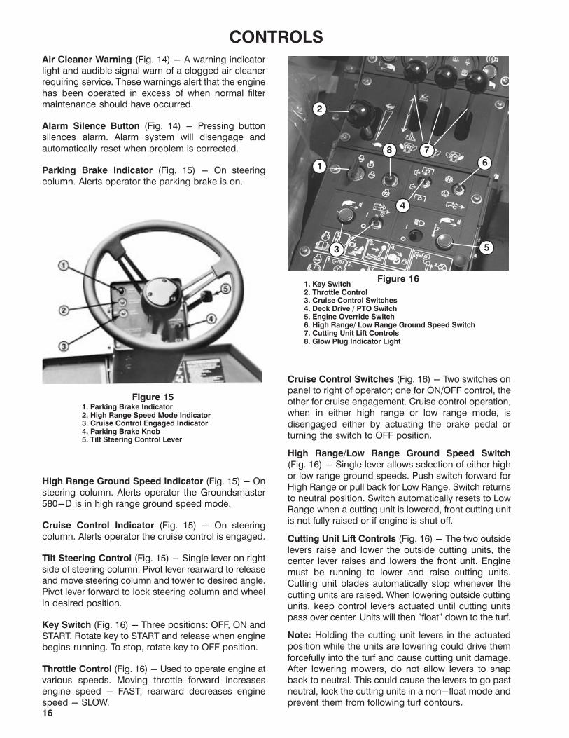
Figure 151. Parking Brake Indicator2. High Range Speed Mode Indicator3. Cruise Control Engaged Indicator 4. Parking Brake Knob5. Tilt Steering Control Lever
High Range Ground Speed Indicator (Fig. 15) - Onsteering column. Alerts operator the Groundsmaster580-D is in high range ground speed mode.
Cruise Control Indicator (Fig. 15) - On steeringcolumn. Alerts operator the cruise control is engaged.
Tilt Steering Control (Fig. 15) - Single lever on rightside of steering column. Pivot lever rearward to releaseand move steering column and tower to desired angle.Pivot lever forward to lock steering column and wheel
in desired position.
Key Switch (Fig. 16) - Three positions: OFF, ON andSTART. Rotate key to START and release when enginebegins running. To stop, rotate key to OFF position.
Throttle Control (Fig. 16) - Used to operate engine atvarious speeds. Moving throttle forward increasesengine speed - FAST; rearward decreases enginespeed - SLOW.
Figure 161. Key Switch2. Throttle Control 3. Cruise Control Switches4. Deck Drive / PTO Switch5. Engine Override Switch6. High Range/ Low Range Ground Speed Switch7. Cutting Unit Lift Controls 8. Glow Plug Indicator Light
1
2
7
3
8
4
6
5
Cruise Control Switches (Fig. 16) - Two switches onpanel to right of operator; one for ON/OFF control, theother for cruise engagement. Cruise control operation,when in either high range or low range mode, is
disengaged either by actuating the brake pedal orturning the switch to OFF position.
High Range/Low Range Ground Speed Switch
(Fig. 16) - Single lever allows selection of either high
or low range ground speeds. Push switch forward forHigh Range or pull back for Low Range. Switch returnsto neutral position. Switch automatically resets to LowRange when a cutting unit is lowered, front cutting unitis not fully raised or if engine is shut off.
Cutting Unit Lift Controls (Fig. 16) - The two outsidelevers raise and lower the outside cutting units, thecenter lever raises and lowers the front unit. Enginemust be running to lower and raise cutting units.Cutting unit blades automatically stop whenever the
cutting units are raised. When lowering outside cuttingunits, keep control levers actuated until cutting unitspass over center. Units will then "float" down to the turf.
Note: Holding the cutting unit levers in the actuatedposition while the units are lowering could drive them
forcefully into the turf and cause cutting unit damage.After lowering mowers, do not allow levers to snapback to neutral. This could cause the levers to go pastneutral, lock the cutting units in a non-float mode andprevent them from following turf contours.
17
CONTROLSGlow Plug Indicator (Fig.16) - Automaticallyactuates proper glow period when ignition key isturned to ON position. Illuminates when glow plugs areactuated. When glow plugs are heated sufficiently,light goes off indicating engine is ready to start.
Deck Drive/PTO Switch (Fig. 16) - Pull sleeve upwardon switch lever and push lever to ENGAGE positionand release to actuate switch; lever will move to neutralposition when released. Move lever to DISENGAGE
position to stop. Switch automatically resets toDISENGAGE when all three cutting units are raised orengine is shut off.
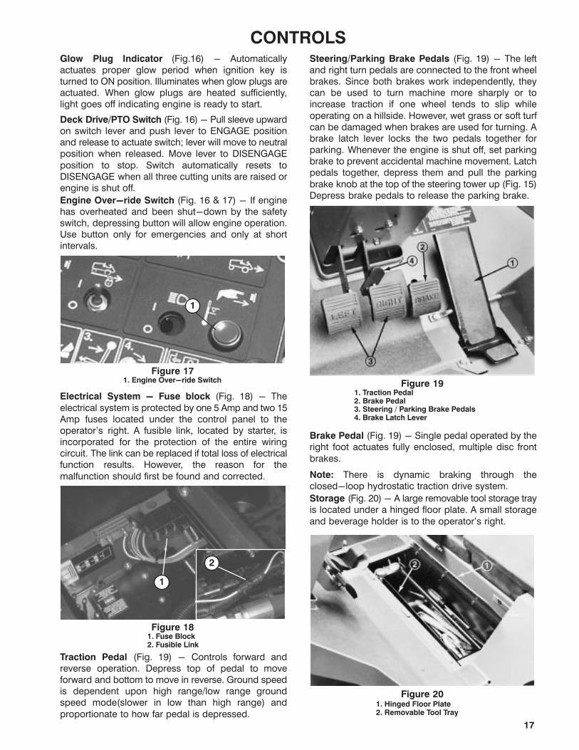
Engine Over-ride Switch (Fig. 16 & 17) - If enginehas overheated and been shut-down by the safetyswitch, depressing button will allow engine operation.Use button only for emergencies and only at shortintervals.
Figure 171. Engine Over-ride Switch
1
Electrical System - Fuse block (Fig. 18) - The
electrical system is protected by one 5 Amp and two 15Amp fuses located under the control panel to theoperator's right. A fusible link, located by starter, isincorporated for the protection of the entire wiringcircuit. The link can be replaced if total loss of electricalfunction results. However, the reason for the
malfunction should first be found and corrected.
Figure 181. Fuse Block2. Fusible Link
2
1
Traction Pedal (Fig. 19) - Controls forward andreverse operation. Depress top of pedal to moveforward and bottom to move in reverse. Ground speedis dependent upon high range/low range groundspeed mode(slower in low than high range) and
proportionate to how far pedal is depressed.
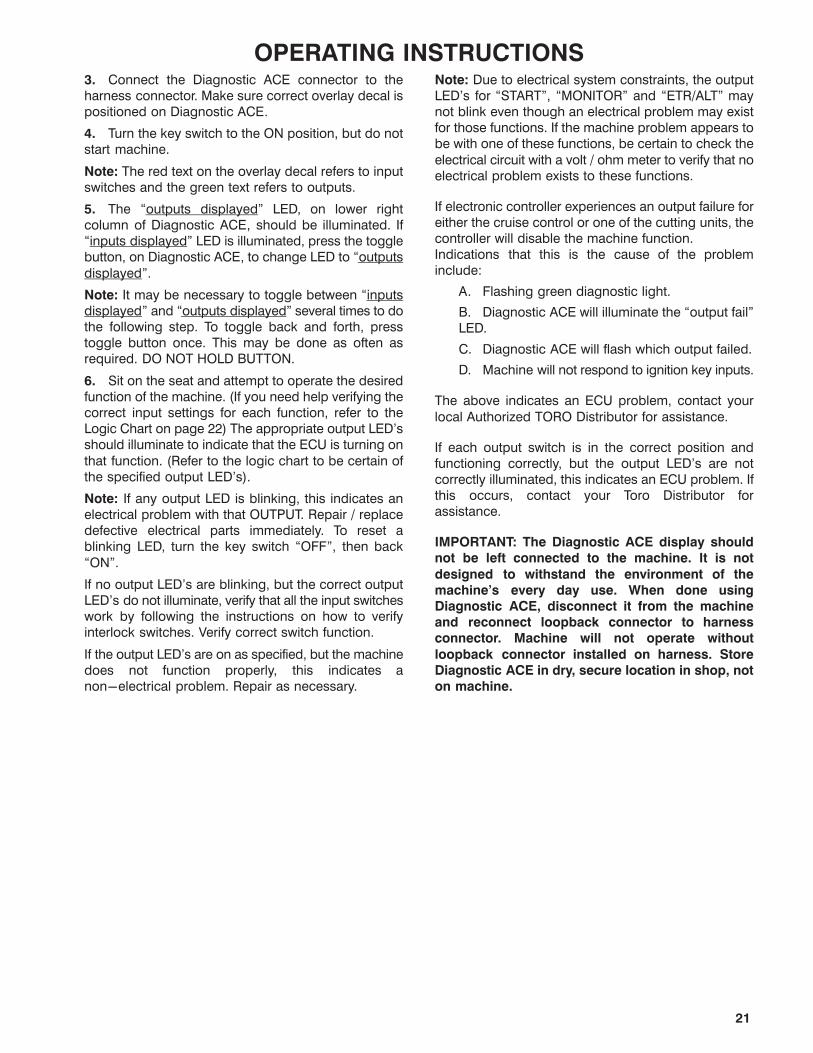
Steering/Parking Brake Pedals (Fig. 19) - The leftand right turn pedals are connected to the front wheelbrakes. Since both brakes work independently, theycan be used to turn machine more sharply or toincrease traction if one wheel tends to slip while
operating on a hillside. However, wet grass or soft turfcan be damaged when brakes are used for turning. Abrake latch lever locks the two pedals together forparking. Whenever the engine is shut off, set parkingbrake to prevent accidental machine movement. Latchpedals together, depress them and pull the parking
brake knob at the top of the steering tower up (Fig. 15)Depress brake pedals to release the parking brake.
Figure 191. Traction Pedal2. Brake Pedal3. Steering / Parking Brake Pedals4. Brake Latch Lever
Brake Pedal (Fig. 19) - Single pedal operated by theright foot actuates fully enclosed, multiple disc front
brakes.
Note: There is dynamic braking through theclosed-loop hydrostatic traction drive system.
Storage (Fig. 20) - A large removable tool storage trayis located under a hinged floor plate. A small storage
and beverage holder is to the operator's right.
Figure 201. Hinged Floor Plate2. Removable Tool Tray

18
OPERATING INSTRUCTIONSIMPORTANT: The fuel system must be bled if any of
the following have occurred:
A. Initial start-up of a new machine.
B. Engine has ceased running due to lack of
fuel.
C. Maintenance has been performed upon fuel
system components; i.e., filter replaced,
separator serviced, etc.
Refer to Bleeding Fuel System.
STARTING/STOPPING ENGINE
1. Sit on seat, keep foot off traction pedal. Ensureparking brake is engaged. Set seat and tilt steeringwheel and tower to comfortable position beforestarting engine.
Figure 211. PTO Switch2. Cruise Control Switches3. HIGH/LOW Range Switch4. Cutting Unit Lift Controls
5. Throttle Lever6. Ignition Key Switch7. Glow Plug Indicator light
1
5
4
2
1
7
3
2. Turn ignition switch to ON position. When glowplug indicator light goes off, engine is ready to START.
3. Rotate ignition key switch to START position(Fig. 21). Release key immediately when engine startsand allow it to return to RUN position.
Note: Do not run starter motor more than 10 secondsat a time or premature starter failure may result. Ifengine fails to start after 10 seconds, turn key to OFFposition. Recheck controls and procedures, wait 10
additional seconds and repeat starting operation.
4. When engine is first started, or after overhaul of theengine, hydrostatic transmission, steering or wheeldrive, operate machine in forward and reverse for oneto two minutes. Turn steering wheel left and right tocheck steering response and operate the lift levers to
check for proper operation. Then, shut engine off, setparking brake and check for oil leaks, loose parts orother malfunctions.
CAUTION
Shut engine off and wait for all moving
parts to stop before checking for oil leaks,
loose parts or other difficulties.
5. Before stopping engine, move HIGH/LOW RANGEground speed switch to LOW, disengage PTO andcruise control switches and move lift levers and tractionpedal to neutral. Move throttle control to SLOWposition. Set parking brake and turn ignition key to
OFF position.
BLEEDING FUEL SYSTEM
1. Unlatch, raise and prop engine hood open andremove left side panel (Fig. 22).
Figure 221. Engine Hood2. Left Side Panel
3. Hood Latches4. Side Panel Latch
2. At lower left side of engine, loosen air bleed screw
at top of fuel filter/water separator (Fig. 23).
Figure 231. Fuel Filter / Water Separator
Note: If fuel tank is over half full, gravity will fill the fuelfilter. If tank is less than half full, fill tank.

19
OPERATING INSTRUCTIONS3. Loosen air vent plug on engine fuel filter assemblyabout 1-1/2 turns (Fig. 24).
4. Rotate priming pump (Fig. 25) counter-clockwiseuntil spring in pump assembly releases. Operate pumpup and down until a solid stream of fuel flows out
around filter plug and tighten plug.
Figure 241. Fuel Filter Air Bleed Plug
1
5. Loosen air vent plug on injection pump about1-1/2 turns (Fig. 25). Operate priming pump until solidstream of fuel flows from the vent hole (Fig. 25), thentighten air vent plug.
6. Push priming pump down to compress spring androtate clockwise to lock closed.
7. Try to start engine. If engine starts, install left sidepanel, lower hood and resume operation. If enginedoes not start, repeat steps 2-7.
Figure 251. Priming Pump2. Injection Pump Air Bleed plug
1
2
DIAGNOSTIC LIGHT
The GM 580-D is equipped with a diagnostic lightwhich indicates if the electronic controller isfunctioning correctly. The green diagnostic light is
located under the control panel. When the electroniccontroller is functioning correctly and the key switch ismoved to the ON position, the controller diagnosticlight will be illuminated. The light will blink if thecontroller detects a malfunction in the electrical
system. The light will stop blinking and automaticallyreset when the key switch is turned to the OFF position.
Figure 261. Electronic Controller Light
1
When the controller diagnostic light blinks, one of thefollowing outputs has been detected in the controller:
1. One of the outputs has been shorted.2. One of the outputs is open circuited.
Using the diagnostic display, determine which outputis malfunctioning, refer to Checking InterlockSwitches.
If the diagnostic light is not illuminated when the keyswitch is in the ON position, this indicates that theelectronic controller is not operating. Possible causes
are:
1. Loopback is not connected.2. Fuses are blown.3. The light is burned out.4. Not functioning correctly.
5. Fusible links are blown
Check electrical connections, input fuses anddiagnostic light bulb to determine malfunction. Makesure loopback connector is secured to wire harnessconnector.
Note: If the diagnostic light flashes during normaloperation of the machine, do not turn off the machine,toggle to the output and touch any switch. The LED will
flash indicating the source of the failure.
DIAGNOSTIC ACE DISPLAY
The GM 580-D is equipped with an electronic
controller which controls most machine functions. Thecontroller determines what function is required forvarious input switches (i.e. seat switch, key switch,etc.) and turns on the outputs to actuate solenoids orrelays for the requested machine function.For the electronic controller to control the machine as
desired, each of the input switches, output solenoidsand relays must be connected and functioningproperly. The Diagnostic ACE display is a tool to help the userverify correct electrical functions of the machine.

20
OPERATING INSTRUCTIONS
CHECKING INTERLOCK SWITCHESThe purpose of the interlock switches are to prevent
the engine from cranking or starting unless the tractionpedal is in NEUTRAL, to ensure cutting unitsdisengage when raised or when operator leaves theseat. In addition, the engine will stop when the tractionpedal is depressed with operator off the seat.
THE INTERLOCK SWITCHES ARE FOR
THE PROTECTION OF THE OPERATOR
AND BYSTANDERS, AND TO ENSURE
CORRECT OPERATION OF THE MA�
CHINE, SO DO NOT BYPASS OR DISCON�
NECT THEM. CHECK OPERATION OF THE
SWITCHES DAILY TO ASSURE INTER�
LOCK SYSTEM IS OPERATING. IF A
SWITCH IS DEFECTIVE, REPLACE IT BE�
FORE OPERATING. THE CONTROLLER
HAS THE ABILITY TO DETECT BYPASSED
SWITCHES AND MAY PREVENT THE OP�
ERATION OF THE MACHINE IF SWITCHES
ARE BYPASSED. DO NOT RELY ENTIRELY
ON SAFETY SWITCHES - USE COMMON
SENSE!
CAUTION
To verify interlock switch function:
1. Park machine on a level surface, lower the cuttingunits, stop the engine and engage the parking brake.
2. Open control panel cover. Locate wire harness andconnectors near controller. Carefully unplug loop backconnector from harness connector (Fig. 27).
Figure 271. Wire Harness and Connectors
1
3. Connect the Diagnostic ACE display connector
(Fig. 28) to the harness connector. Make sure correctoverlay decal is positioned on Diagnostic ACE display.
4. Turn the key switch to the ON position, but do notstart machine.
Figure 281. Diagnostic ACE
Note: The red text on the overlay decal refers to inputswitches and the green text refers to outputs.
5. The �inputs displayed" LED, on lower right column
of the Diagnostic ACE, should be illuminated. If�outputs displayed" LED is illuminated, press thetoggle button, on Diagnostic ACE, to change LED to�inputs displayed".
6. The Diagnostic ACE will illuminate the LEDassociated with each of the inputs when that inputswitch is closed.
Individually, change each of the switches from open toclosed (i.e., sit on seat, engage traction pedal, etc.),and note that the appropriate LED on Diagnostic ACEwill blink on and off when corresponding switch isclosed and opened. Repeat on each switch that it ispossible to be changed by hand.
7. If switch is closed and appropriate LED does notblink on and off, check all wiring and connections to
switch and/or check switches with an ohm meter.Replace any defective switches and repair anydefective wiring.
Now start engine and raise and lower each cutting unit.Note the appropriate LED on the Diagnostic ACE (i.e.LED is illuminated when cutting unit is lowered andLED is not illuminated when cutting unit is raised.
The Diagnostic ACE also has the ability to detect whichoutput solenoids or relays are turned on. This is a quickway to determine if a machine malfunction is electrical
or hydraulic.
To verify output function:
1. Park machine on a level surface, lower the cuttingunits, stop the engine and engage the parking brake.
2. Open control panel cover. Locate wire harness andconnectors near controller. Carefully unplug loopbackconnector from harness connector.
21
OPERATING INSTRUCTIONS3. Connect the Diagnostic ACE connector to theharness connector. Make sure correct overlay decal ispositioned on Diagnostic ACE.
4. Turn the key switch to the ON position, but do notstart machine.
Note: The red text on the overlay decal refers to inputswitches and the green text refers to outputs.
5. The �outputs displayed" LED, on lower rightcolumn of Diagnostic ACE, should be illuminated. If�inputs displayed" LED is illuminated, press the togglebutton, on Diagnostic ACE, to change LED to �outputs
displayed".
Note: It may be necessary to toggle between �inputsdisplayed" and �outputs displayed" several times to dothe following step. To toggle back and forth, presstoggle button once. This may be done as often asrequired. DO NOT HOLD BUTTON.
6. Sit on the seat and attempt to operate the desiredfunction of the machine. (If you need help verifying thecorrect input settings for each function, refer to theLogic Chart on page 22) The appropriate output LED'sshould illuminate to indicate that the ECU is turning on
that function. (Refer to the logic chart to be certain ofthe specified output LED's).
Note: If any output LED is blinking, this indicates anelectrical problem with that OUTPUT. Repair / replacedefective electrical parts immediately. To reset ablinking LED, turn the key switch �OFF", then back
�ON".
If no output LED's are blinking, but the correct outputLED's do not illuminate, verify that all the input switcheswork by following the instructions on how to verifyinterlock switches. Verify correct switch function.
If the output LED's are on as specified, but the machinedoes not function properly, this indicates anon-electrical problem. Repair as necessary.
Note: Due to electrical system constraints, the outputLED's for �START", �MONITOR" and �ETR/ALT" maynot blink even though an electrical problem may existfor those functions. If the machine problem appears tobe with one of these functions, be certain to check the
electrical circuit with a volt / ohm meter to verify that noelectrical problem exists to these functions.
If electronic controller experiences an output failure foreither the cruise control or one of the cutting units, thecontroller will disable the machine function.Indications that this is the cause of the probleminclude:
A. Flashing green diagnostic light.
B. Diagnostic ACE will illuminate the �output fail"LED.
C. Diagnostic ACE will flash which output failed.
D. Machine will not respond to ignition key inputs.
The above indicates an ECU problem, contact your
local Authorized TORO Distributor for assistance.
If each output switch is in the correct position andfunctioning correctly, but the output LED's are notcorrectly illuminated, this indicates an ECU problem. Ifthis occurs, contact your Toro Distributor forassistance.
IMPORTANT: The Diagnostic ACE display should
not be left connected to the machine. It is not
designed to withstand the environment of the
machine's every day use. When done using
Diagnostic ACE, disconnect it from the machine
and reconnect loopback connector to harness
connector. Machine will not operate without
loopback connector installed on harness. Store
Diagnostic ACE in dry, secure location in shop, not
on machine.

22
OP
ER
AT
ING
INS
TR
UC
TIO
NS
X Run (with operator)
B= MUST BE CLOSED ONLY IF HI TEMP SWITCH IS CLOSED.
1) Start
ACTIONS
LOGIC
GRID
INP
UT
S
0 H
i R
an
ge
Dis
en
gag
e
1 P
ark
ing
Bra
ke
(X
=O
FF
)
2 K
ey R
un
3 T
racti
on
Ne
utr
al
4 S
eat
Sw
itch
5 H
igh
Co
ola
nt
Tem
p
6 H
igh
Te
mp
Ove
rrid
e
7 C
ruis
e C
on
tro
l E
nab
le
8 P
TO
En
gag
e
9 P
TO
Dis
en
gag
e
10 F
ron
t D
eck D
ow
n
11 R
igh
t D
eck D
ow
n
12 L
eft
De
ck D
ow
n
13 H
i R
an
ge
En
gag
e
14 H
yd
. O
il L
eve
l (x
=o
k)
15 C
ruis
e C
on
tro
l E
ng
ag
e
16 S
erv
ice
Bra
ke
(x=
off
)
17
AO
Sta
rt K
ey
OU
TP
UT
S
0
1 2 R
igh
t D
eck E
ng
ag
e
3 L
eft
De
ck E
ng
ag
e
4 G
au
ge
Po
we
r O
N
5
Fro
nt
De
ck E
ng
ag
e
6 C
ruis
e C
on
tro
l C
lutc
h
7 E
TR
Ho
ld /
Alt
8
9
Ou
tpu
t Fail
10 H
arn
ess
11
12 S
tart
13 H
i R
an
ge
En
gag
e
KEY:
X=CLOSED, O=OPEN, P=OUTPUT ON,
M=MOMENTARILY CLOSED,
X
X
/
2) Hi Range Engage
3) Run (no operator)
4) Cruise Engage
5) Front Deck Engage
6) Right Deck Engage
7) Left Deck Engage
8) Gauges ON
O
O
O
X
X
X
X
X
X
X
X
O X
X
X
X
X
O
O
O
O
O
B
B
X
M
M
M
O
O
O
O
X
O O
X
O
X
O
O
O
M
X
X
X
X
P
P
P
P
P
P
P
P P
P
M

23
OPERATING INSTRUCTIONSCHECK WARNING INDICATOR LIGHTS
Each day, before operating assure all warning lightsare functioning:
1. Sit on seat and apply parking brake. Turn ignitionkey ON and push TEST button. All lights shouldilluminate.
2. If a light fails to illuminate, replace the bulb and testagain.
PUSHING OR TOWING MACHINE
In an emergency, the Groundsmaster 580-D can bemoved by the following methods:
A. Actuate the by-pass valve in the variabledisplacement hydraulic pump and push or tow themachine.
B. Unlock the front hubs and tow the machine.
DANGER
There is no effective braking of the
Groundsmaster 580-D with the wheel
hubs disengaged. Unless it is on a level
surface or the wheels are blocked, the
machine will move freely. Do not unlock
the wheel hubs without either blocking the
wheels or connecting the machine to a
towing vehicle by means of a rigid towing
device.
Pump By-pass Method (short distances only)
IMPORTANT: Do not push or tow the machine faster
than 2-3 mph (3-4.8 km/hr) because internal
transmission damage may occur. The by-pass
valve must be open whenever the machine is
pushed or towed by this method, TORO does not
recommend this process be used as standard
procedure.
1. By-pass valve is located in left side of variabledisplacement pump (Fig. 29). Rotate the valve 1/2 to 1turn counter-clockwise to open and allow oil toby-pass internally. Because fluid is by-passed, themachine can be moved - slowly - without damagingthe transmission.
2. Rotate the valve clockwise until it is securely
seated before starting the engine. However, do notexceed 5-8 ft-lb (7-11 N m) torque to close the valve.
IMPORTANT: Running the engine with the by-pass
valve open will cause the transmission to overheat.
Figure 291. By-Pass Valve
Unlocked Hub Method
1. Either block the wheels or connect the machine toa towing vehicle with a rigid towing device.
Vehicle will roll with front wheel hubs
disengaged. Vehicle must be on a level
surface or wheels must be blocked. There
is no effective braking with wheel hubs
disengaged.
DANGER
2. Remove bolts securing the disengage covers toboth front wheel hubs.
3. Face the dimpled portion of the disengaged covers
inward and reinstall the covers. Wheel hubs are nowunlocked.
4. Lock the wheel hubs immediately after towingoperations are completed. Remove disengage coversand reinstall with the dimpled portion facing away fromthe wheel hubs.
CAUTION
Do not remove wheel blocks or towing
devices until wheel hubs are securely
locked.
OPERATING CHARACTERISTICS
Familiarization - Before mowing for the first time,
practice operating in a large, open and relatively levelarea. Start and stop the engine, operate in forward andreverse in LOW RANGE ground speed. Practice usingthe cruise control. Lower and raise cutting unitsindividually and simultaneously. When thoroughlyfamiliar with machine functions, practice operating
around trees and obstacles while using the individualwheel brakes. Also operate up and down slopes (INLOW RANGE).

24
OPERATING INSTRUCTIONSNote: TORO recommends HIGH RANGE groundspeed be used for road travel only (with cutting unitsup).
Points to consider while operating the traction unit,
cutting units or other implements are the hydrostatictransmission, engine speed, load on the cutting bladesor other implement components and the importance ofthe brakes. To maintain adequate power for thetraction unit and implement components whileoperating, regulate traction pedal position to keep
engine rpm high and relatively constant. Good rules tofollow are; decrease ground speed as the implementload increases, and increase ground speed as the loaddecreases.
Warning Systems - If a warning light and audiblewarning come on during operation, stop immediatelyand correct the problem before continuing. Seriousdamage could occur if the machine is operated with anuncorrected problem. However, if the engine stops
because of overheating, the emergency over-ridebutton can be used to operate the engine for shortintervals (Fig. 30).
Figure 301. Engine Over-ride Button
1
Mowing - When approaching area to mow, positionthe ground speed selector in LOW RANGE and
release. Switch lever will return to neutral and HighRange light will go out. Move the throttle lever to FASTand lower the cutting units. Pull the sleeve of the deckdrive PTO switch up, position it in ENGAGE positionand release. Lever will return to neutral position and
PTO will be engaged automatically. Depress tractionpedal slowly to begin cutting operation.
Note: After lowering mowers, do not allow levers tosnap back to neutral. This could allow the levers to go
past neutral, lock the cutting units in a non-float modeand prevent them from following turf contours.
Should either outboard cutting unit contact animmovable object while mowing, the mower lift armlatch assembly absorbs the impact and breaks away.
This allows the cutting unit to swing rearward. Shouldthis occur, stop the machine. Fully raise the cuttingunit, then lower it to cutting position. This will allow thelift arm latch assembly to return to normal
configuration. Be sure to inspect the cutting unit fordamage and repair as necessary before resumingoperation.
Caution: This product may exceed noise levels of 85
dB(A) at the operator position. Ear protectors arerecommended for prolonged exposure to reduce thepotential of permanent hearing damage.
The individual wheel brakes can be used to assist in
turning the machine. However, use them carefully,especially on soft or wet turf because it may be tornaccidentally. The brakes are also beneficial to maintaintraction; for example, in some slope conditions, theuphill wheel may slip and lose traction. If this occurs,gradually depress the uphill brake pedal until the uphill
wheel stops slipping, thus increasing traction on thedownhill wheel.
To stop mowing, depress the brake pedal to stop anddisengage the cruise control (if used), move the PTO
switch to DISENGAGE and release (switch returns toneutral), then fully raise the cutting units.
High Range Ground Speed Operation - Tororecommends HIGH RANGE ground speed operation
be performed only on roads with the cutting units infully raised position. Start the machine in LOW RANGE,then shift to HIGH RANGE. The HIGH RANGE Indicatorlight will turn ON, indicating the machine is in the HIGHRANGE mode. To cease HIGH RANGE operation, take
foot off traction pedal and apply the brakes. Movethrottle lever to SLOW and position ground speedselector in LOW RANGE. If the engine begins to laborwhile climbing an incline, ease off on the traction pedaland shift to LOW RANGE. This will prevent overload ofthe engine and hydraulic system.
CAUTIONUse extreme care while operating in HIGH
RANGE ground speed selection. Watch
closely for bystanders, other vehicles and
possible hidden hazards and be prepared
to stop quickly.
Cruise Control Operation-While operating themachine at the desired ground speed, turn the cruisecontrol switch to ON and press the cruise control
actuating button. The traction pedal will be held in itsposition and a constant ground speed will bemaintained. A light on the steering column indicatesthe cruise control is in operation. Ground speed can bechanged by over-riding the traction pedal. The pedalwill maintain its new position when the over-riding
force is released.
To stop cruise control operation: Turn cruise controlswitch to OFF position or depress the service brake.

25
OPERATING INSTRUCTIONSNote: Hold the traction pedal in position whenstopping cruise control operation, otherwise themachine will stop abruptly due to hydrostatic brakingaction.
If it is an emergency and it becomes necessary to stop
suddenly while in cruise control, depress the servicebrake pedal, this breaks the electrical circuit, returnsthe traction pedal to neutral and stops the machine.
Stopping the Machine - To stop the machine andcease operation, take foot off traction pedal and applythe brakes. Move the throttle lever to SLOW, groundspeed selector to LOW RANGE and deck lift controls toneutral. Switch cruise control to OFF, set the parking
brake and turn ignition key to OFF. Remove the key ifthe machine is to be left unattended.
LUBRICATIONThe following must be lubricated regularly with No. 2 general purpose lithium or molybdenum base grease.
The chart below lists service intervals based upon normal operating conditions. However, lubricate more
frequently under extreme conditions. The left column numbers correspond with numbers in Fig. 31.
Component No. of Fittings Service intervalCenter Cutting Unit
1. Castor Fork Shaft Bushings 2 Every 8 hours or daily.
2. Spindle Shaft Bearings 5 Every 50 hours.
3. Idler Pulley Bushings 2 Every 50 hours
4. Deck Hinge Pivot Bushings 2 Every 50 hours.
Right & Left Hand Cutting Units
5. Castor Fork Shaft Bushings 8 Every 8 hours or daily
6. Spindle Shaft Bearings 6 Every 50 hours.
Front Lift Arm Assemblies
7. L.H. & R.H. Lift Arm 3 Every 50 hours.
8. Hydraulic Cylinder Pivot Bushings 4 Every 50 hours.
9. Lift Arm Ball Joints 2 Every 50 hours
Outboard Cutting Unit Lift Assemblies
10. Lift Arm Pivots 4 Every 50 hours.
11. Anti-sway Arm Bushings 2 Every 50 hours.
12. Lift Arm Elbow Shaft Bushings 4 Every 50 hours.
13. Latch Ball Joints 4 Every 50 hours.
14. Hydraulic Cylinder Pivot Bushing 4 Every 50 hours.
15. Lift Clevis Pivot Bushings 2 Every 50 hours.
Traction Unit
16. Steering Brake Pedal Arms 2 Every 50 hours.
17. Engine Water Pump Assy. 1 Every 50 hours.
18. Engine to Pump Drive Yoke 3 Every 50 hours.
19. Rear Wheel Spindle Bushings 2 Every 50 hours.
20. Rear Axle Pivot Bushings 1 Every 50 hours
21. Steering Tie Rod Ball Joint 2 Every 50 hours.
22. Service Brake Pivot Bushings 1 Every 50 hours.
23. Hydraulic Steering Cylinder Ball Joints 2 Every 50 hours.
24. Rear Wheel Bearings 2 Repack every 1000 hours
Refer to chart, page 25 and Figure 31 for areas to lubricate and number of fittings involved.

26
LUBRICATION
Figure 31
1 1
24
2 2
34
29
23
9
16 22
7 7
8
7
8
5
5
13 13
5
5
156
6
156
5
156
13
10
11
5
12
14
1218
14
12
13
10
11
5
512
1414
17
24
2124
1920
2123
19
24
8
6
6

27
DAILY MAINTENANCE CHECKLIST
Daily Maintenance: (duplicate this page for routine use)
Maintenance Daily Maintenance Check For Week Of ___________MaintenanceCheck Item � MON TUES WED THURS FRI SAT SUN
� Safety Interlock Operation
� Brake Operation
� Engine Oil Level
� Cooling System Fluid Level
Drain Water/Fuel Separator
� Air Filter/Pre–Cleaner Condition
� Radiator & Screen for Debris
� Unusual Engine Noises
� Unusual Operating Noises
� Height of Cut
� Hydraulic System Oil Level
� Hydraulic Hoses for Damage
� Fluid Leaks
� Tire Pressure
� Instrument Operation
� Condition of Blades
Lubricate All Grease Fittings2
Touch–up Damaged Paint
1=Immediately after every washing, regardless of the interval listed.
Notation for areas of concern: Inspection performed by_____________________________
Item Date Information
1
2
3
4
5
6
7
Check proper section of Operator's Manual for fluid specifications

28
MAINTENANCE
CAUTION
Before performing machine maintenance,
park on a level surface, set the parking
brake, fully lower cutting units, shut en�
gine off and remove key from ignition
switch. If engine must be running to
perform maintenance or adjustment, stay
clear of moving parts. If engine has been
operating shortly before maintenance has
begun, avoid engine, muffler, turbo-char�
ger and radiator as they may be hot
enough to cause injury.
ENGINE OIL AND FILTER
The engine uses any high quality detergent oil having
the American Petroleum Institute - API - �serviceclassification" CD. Oil viscosity recommendations are:
AMBIENT TEMPERATUREPROPER
VISCOSITY
-20� to 20� F (-28.9� to -6.7� C)
105� F (40.6� C) and up
20� to 105� F (-6.7� to 40.6� C) SAE 30
SAE 40
SAE 10
Note: Do not use multi-viscosity oils.
Oil Level Check
Check engine oil level after every five hours operation.
1. Unlatch and raise hood and prop it open.Unlatch and remove left side panel (Fig. 32). Make sure
hood prop is secured in one of the mounting bracketson hood.
Figure 321. Engine Hood2. Left Side Panel
3. Hood Latches4. Side Panel Latch
2. Remove dipstick, wipe with clean rag (Fig. 33) andfully re-insert in tube. Remove from tube and check oillevel. Level should be between the marks on thedipstick. If level is low, remove filler cap (Fig. 34). Addoil until level is to top mark on dipstick. DO NOT
OVERFILL.
Figure 331. Dipstick
1
Figure 341. Engine Oil Fill Cap
1
Changing Engine Oil and Filter
The engine holds approximately 10.6 qt (10 l) of oil.Change oil and filter after the first 50 hours, thenchange both every 100 hours operation. However,change oil more frequently when engine is operated industy or sandy conditions. If possible, run engine justbefore changing oil because warm oil flows better and
carries more contaminants than cold oil.
1. Unlatch and raise hood and prop it open (Fig. 32).Make sure hood prop is secured in one of the mountingbrackets on hood. Unlatch and remove both sidepanels (Fig. 32).

29
MAINTENANCE2. Place drain pan in line with the drain plug (Fig. 35).
Clean area around drain plug.
Figure 351. Engine Oil Drain Plug
1
3. Remove drain plug and allow oil to drain into pan.
Remove and replace oil filter (Fig. 36); refer to parts
catalog for replacement number. Apply a coating of oil
to the filter O-ring and tighten filter by hand.
Figure 361. Engine Oil Filter
1
ENGINE FUEL SYSTEM
1. Locate fuel filter/water separator on lower left side
of engine and drain daily (Fig. 37).
2. Every 200 hours operation, replace filter element of
the fuel filter/water separator.
Figure 371. Fuel Filter/Water Separator2. Water Drain Plug
3. Every 1000 hours operation, or yearly, replace theengine fuel filter (Fig. 38) - left front side of engine -and drain water from the fuel tank. Apply clean fuel oil
to the filter O-ring. Use hands only to install andtighten filter.
4. If fuel system becomes contaminated or machineis to be stored for an extended period, locate drain atbottom of fuel tank and drain and clean tank. Flushtank with clean fuel oil.
Figure 381. Engine Fuel Filter
1
IMPORTANT: Following the maintenance steps
listed above will, under normal conditions, keep the
system trouble-free. However, if the indicator light
on the control panel and audible warning signal
activate during operation, the engine should be
stopped and the fuel system serviced before
operation is resumed. This can prevent serious
engine damage from occurring.

30
MAINTENANCEENGINE COOLING SYSTEM
The cooling system holds approximately 3.9 gal (14.7 l)of a 50/50 solution of ethylene glycol anti-freeze andwater. To properly maintain the system, use thefollowing procedures:
1. Check coolant level each day before starting theengine; refer to Check Cooling System in BeforeOperating section.
CAUTION
Check coolant level before the engine has
been started because coolant system will
not be pressurized. When the engine is hot
and the radiator cap removed, hot pres�
surized coolant can escape and cause
burns. If engine coolant is hot, slowly and
carefully remove radiator cap.
2. Each day after operation, clean debris from theradiator grille. Clean more frequently in dusty and dirtyconditions.
A. Move seat forward as far as possible.
B. Remove upper and lower grille assemblies(Fig. 39).
C. Use compressed air to clean the grilles andremove debris from grille mounting areas.
D. Install grilles after cleaning, lower and lockseat in position.
Figure 391. Upper Grille 2. Lower Grille
3. Every 100 hours operation, clean the radiator andhydraulic cooler fins. Clean more frequently in dustyand dirty conditions.
A. Use procedures in step 2, items a-c.
B. Unlatch latch handles on both sides andremove radiator cowl and grille support (Fig. 40).
Figure 401. Latch Handles2. Radiator Cowl
3. Grille Support
C. Remove wing nuts securing top of oil cooler to upper radiator support and pivot top of oil cooleraway from radiator (Fig. 41).
D. Unlatch and raise hood and prop it open. Usecompressed air from the engine fan side to clean
the radiator and oil cooler fins.
E. Re-assemble components after cleaning is
completed.
Figure 411. Oil Cooler 2. Radiator 3. Wing Nuts
4. Every 100 hours operation, inspect fan belt forcondition and proper tension. Replace belt if conditionwarrants. Check and adjust tension as follows:
A. Unlatch and raise hood and prop it open. Unlatch and remove right side panel.
B. Proper tension will allow 1/2 in. (13 mm)deflection when a force of 10 lbs. is applied on thebelt midway between the pulleys. If deflection isincorrect, proceed to step c; If deflection is correct,install panel and close hood.
C. Loosen bolts (3) securing alternator to plateand mounting bracket (Fig. 42). Rotate alternator
away from engine to increase tension and tightenbolts. Check belt tension after adjustment andre-adjust, if necessary.
31
MAINTENANCE
Figure 42
1. Alternator
1
D. Install panel and close hood.
5. Every 100 hours operation, check condition ofcooling system hoses and tightness of connections.Repair, as needed.
6. Every 1000 hours, or yearly, drain and flush thecooling system and replace the thermostat and hoseassemblies.
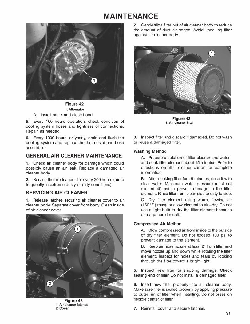
GENERAL AIR CLEANER MAINTENANCE
1. Check air cleaner body for damage which couldpossibly cause an air leak. Replace a damaged aircleaner body.
2. Service the air cleaner filter every 200 hours (morefrequently in extreme dusty or dirty conditions).
SERVICING AIR CLEANER
1. Release latches securing air cleaner cover to aircleaner body. Separate cover from body. Clean insideof air cleaner cover.
1. Air cleaner latches2. Cover
Figure 43
1
2
2. Gently slide filter out of air cleaner body to reducethe amount of dust dislodged. Avoid knocking filteragainst air cleaner body.
1. Air cleaner filterFigure 43
1
3. Inspect filter and discard if damaged. Do not wash
or reuse a damaged filter.
Washing Method
A. Prepare a solution of filter cleaner and water
and soak filter element about 15 minutes. Refer todirections on filter cleaner carton for completeinformation.
B. After soaking filter for 15 minutes, rinse it with
clear water. Maximum water pressure must notexceed 40 psi to prevent damage to the filterelement. Rinse filter from clean side to dirty to side.
C. Dry filter element using warm, flowing air
(160�F ) max), or allow element to air-dry. Do notuse a light bulb to dry the filter element becausedamage could result.
Compressed Air Method
A. Blow compressed air from inside to the outsideof dry filter element. Do not exceed 100 psi toprevent damage to the element.
B. Keep air hose nozzle at least 2" from filter andmove nozzle up and down while rotating the filterelement. Inspect for holes and tears by lookingthrough the filter toward a bright light.
5. Inspect new filter for shipping damage. Check
sealing end of filter. Do not install a damaged filter.
6. Insert new filter properly into air cleaner body.Make sure filter is sealed properly by applying pressureto outer rim of filter when installing. Do not press onflexible center of filter.
7. Reinstall cover and secure latches.

32
MAINTENANCEHYDRAULIC SYSTEM SERVICE
Listed below are hydraulic oil brands recommendedfor the 580-D. All are interchangeable with one
another.
Mobil DTE 15 MMobil DTE 26Shell Tellus 68Amoco Rykon Oil #68Conoco Super Hydraulic Oil 68Exxon Nuto H 68Kendall Kenoil R & O AW 68Pennzoil Penreco 68Phillips Magnus A 68Standard Energol HLP 68Sun Sunvis 831 WRUnion Unax AW 68
IMPORTANT: Use only hydraulic oils specified.
Other fluids could cause system damage.
Note: A red dye additive for the hydraulic system oil isavailable in 2/3 oz (20 ml) bottles. One bottle issufficient for 4-6 gal (15-23 l) of hydraulic oil. Order
Part No. 44-2500 from your Authorized ToroDistributor.
Check Oil Level
1. Visually check hydraulic oil level daily through
sight glass (Fig. 46). With machine on a level surface,oil should be in the middle of the sight glass whenwarm and slightly below level when cold.
2. If oil needs to be added, clean area thoroughlyaround the fill cap before removing cap (Fig. 46). Add
oil until proper level is indicated in sight glass.
Figure 461. Hydraulic Oil Level Sight Glass 2. Reservoir Fill Cap
Replace Hydraulic Filter (Initial)
After 50 hours initial operation, replace the hydraulicfilter (Toro Part No. 69-1720).
1. Place drain pan under filter and remove filter(Fig. 47).
Figure 471. Hydraulic Oil Filter
2. Coat O-ring of the replacement filter with clean
hydraulic oil before installing.
3. To tighten filter, hand turn filter element onto filterhead until element is firmly seated against the head.
4. Start engine and check for leaks. Check oil levelafter engine has been stopped. Add oil, if necessary.
Inspect Lines and Fittings
Every 100 hours operation inspect all hoses, lines andfittings for signs of leakage or damage (blisters, cut
hoses, etc.)
CAUTION: Replace any suspect hoses or lines
immediately to prevent machine damage or
personal injury.
CAUTION
Keep body and hands away from pin hole
leaks or nozzles that eject hydraulic fluid
under high pressure. Use paper or card�
board, not hands, to search for leaks.
Hydraulic fluid escaping under pressure
can have sufficient force to penetrate skin
and do serious damage. If fluid is injected
into the skin it must be surgically removed
within a few hours by a doctor familiar with
this form of injury or gangrene may result.
Replace Hydraulic Filter
Every 500 hours operation, replace the filter element;refer to Replace Hydraulic Filter.
Drain Water From Hydraulic Reservoir
Every 500 hours operation, drain water from reservoirat three (3) locations.
1. Place drain pan under reservoir.
2. Locate plugs at right rear behind front wheel, atrear center and front center of reservoir (Fig. 48).
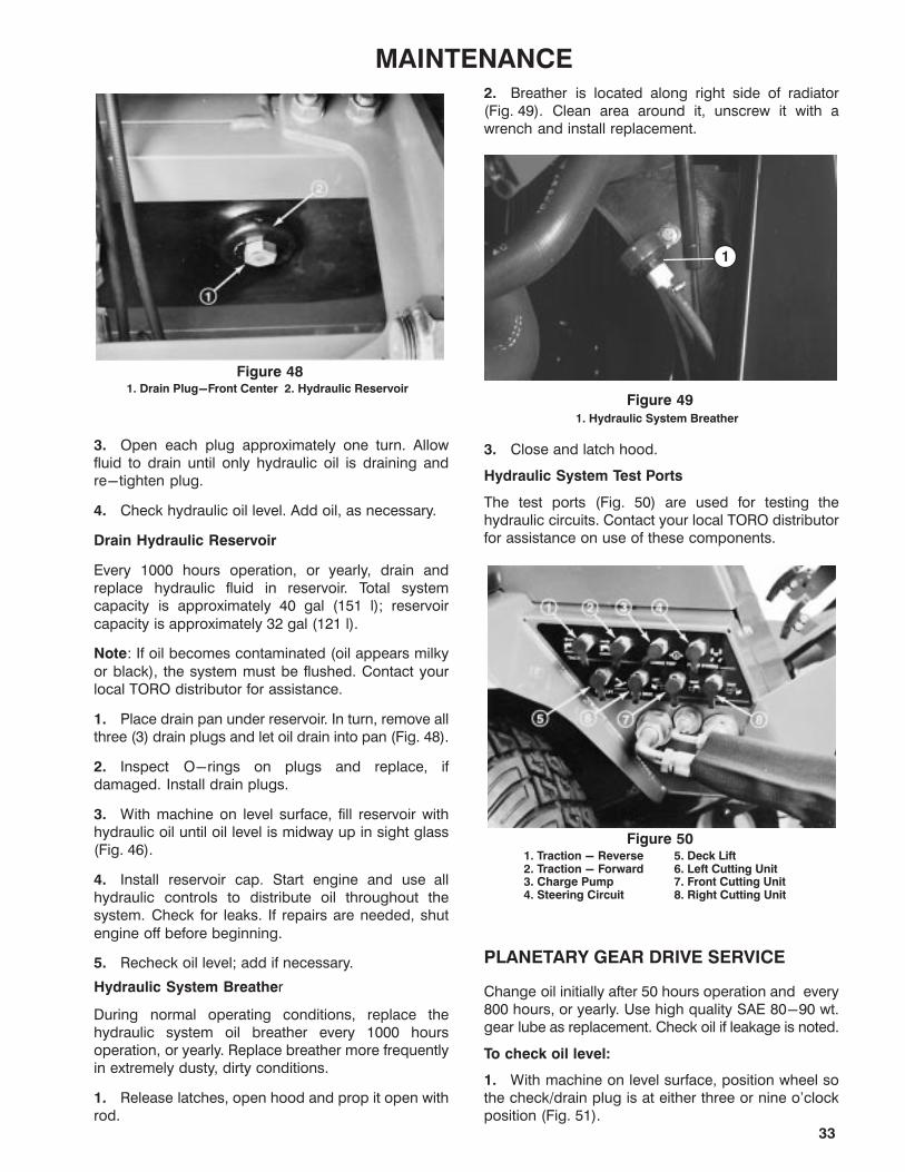
33
MAINTENANCE
Figure 481. Drain Plug-Front Center 2. Hydraulic Reservoir
3. Open each plug approximately one turn. Allowfluid to drain until only hydraulic oil is draining andre-tighten plug.
4. Check hydraulic oil level. Add oil, as necessary.
Drain Hydraulic Reservoir
Every 1000 hours operation, or yearly, drain andreplace hydraulic fluid in reservoir. Total systemcapacity is approximately 40 gal (151 l); reservoir
capacity is approximately 32 gal (121 l).
Note: If oil becomes contaminated (oil appears milky
or black), the system must be flushed. Contact yourlocal TORO distributor for assistance.
1. Place drain pan under reservoir. In turn, remove allthree (3) drain plugs and let oil drain into pan (Fig. 48).
2. Inspect O-rings on plugs and replace, ifdamaged. Install drain plugs.
3. With machine on level surface, fill reservoir withhydraulic oil until oil level is midway up in sight glass(Fig. 46).
4. Install reservoir cap. Start engine and use allhydraulic controls to distribute oil throughout thesystem. Check for leaks. If repairs are needed, shut
engine off before beginning.
5. Recheck oil level; add if necessary.
Hydraulic System Breather
During normal operating conditions, replace thehydraulic system oil breather every 1000 hoursoperation, or yearly. Replace breather more frequentlyin extremely dusty, dirty conditions.
1. Release latches, open hood and prop it open withrod.
2. Breather is located along right side of radiator(Fig. 49). Clean area around it, unscrew it with awrench and install replacement.
Figure 491. Hydraulic System Breather
1
3. Close and latch hood.
Hydraulic System Test Ports
The test ports (Fig. 50) are used for testing thehydraulic circuits. Contact your local TORO distributorfor assistance on use of these components.
Figure 501. Traction - Reverse2. Traction - Forward3. Charge Pump4. Steering Circuit
5. Deck Lift6. Left Cutting Unit7. Front Cutting Unit8. Right Cutting Unit
PLANETARY GEAR DRIVE SERVICE
Change oil initially after 50 hours operation and every800 hours, or yearly. Use high quality SAE 80-90 wt.gear lube as replacement. Check oil if leakage is noted.
To check oil level:
1. With machine on level surface, position wheel sothe check/drain plug is at either three or nine o'clockposition (Fig. 51).

34
MAINTENANCE
Figure 511. Check/Drain Plug(3 or 9 o'clock position)
2. Remove plug. Oil should be to bottom of the hole.
3. Add gear oil, if necessary, to bring up to properlevel and install plug.
4. Repeat steps 1-3 on the opposite gear assembly.
To Drain Gear Oil:
1. With machine on level surface, position wheel sothe check/drain plug is at lowest position.
2. Place drain pan under hub, remove plug and allowoil to drain.
3. When oil has drained, position wheel so plug hole
is at three or nine o'clock position (Fig. 51).
4. Add approximately 32 oz (1.24 l) high quality SAE80-90 wt. gear lube to bring level up to bottom of hole
and install plug.
5. Repeat steps 1-4 on the opposite gear assembly.
BATTERY SERVICE
IMPORTANT: Before welding on the machine or
performing service to the electrical system,
disconnect negative (-) battery cable from the
batteries to prevent damage to the electrical
system.
Check battery cables and connections every 100hours and check batteries with a hydrometer every 500
hours operation. Keep terminals and entire batterycase clean. Clean batteries with a solution of bakingsoda and water, then rinse with clear water. To preventcorrosion, coat battery posts and cable connectorswith Grafo 112X (Skin-over) grease, TORO Part No.505-47.
CAUTION
Wear safety goggles and rubber gloves
when working with the batteries. Charge
batteries in a well-ventilated place so
gases produced while charging can dissi�
pate. Since the gases are explosive, keep
electrical spark and open flame away from
the batteries. Do not smoke. Nausea may
result if the gases are inhaled. Unplug
charger from electrical outlet before con�
necting to or disconnecting charger leads
from battery posts.
1. Unlatch, raise and prop hood open. Unlatch andremove left engine side panel.
2. Remove capscrews securing battery tray tomachine and slide tray out (Fig. 52).
3. Check both batteries for charge with a hydrometer.
If batteries check acceptably, slide tray back in place,secure with capscrews and install side panel. Ifbatteries require charging, proceed to step 4.
4. Remove negative (-) battery cable connectorsfrom batteries (Fig. 52). Connect a 3 to 4 Amp batterycharger to the posts. Charge the batteries at a rate of 3
to 4 Amperes for 4 to 8 hours.
Figure 521. Battery Tray 2. Negative (-) Cable Connectors
5. When batteries are fully charged, disconnectcharger from electrical outlet and battery posts.
6. Connect negative (-) cable ends, slide tray backin place, and secure with capscrews. Install side panel,close hood and secure both with latches.

35
MAINTENANCEFUSES & CIRCUIT BREAKER
One 5 Amp, two 15 Amp fuses and a fusible link are
incorporated for the protection of the entire wiringcircuit. The link can be replaced if total loss of electricalfunction results. They are located under the controlpanel to the right of the seat (Fig. 53). If total loss ofelectrical function occurs, find and correct the
malfunction before replacing the fusible link.
Figure 531. Fuse Block
1
IMPORTANT: Do not install fuses in fuse block on leftside of instrument control panel. Fuses should be
installed in this fuse block only if machine is equippedwith a road light kit.
BRAKE SYSTEM SERVICE
Check brake fluid level every 50 hours operation.Replace fluid every 1000 hours operation, or yearly.Replenish system with DOT 3 hydraulic brake fluid. Tocheck fluid level:
1. Raise floor panel in front of seat (Fig. 54). Remove
tool tray.
Figure 541. Floor Plate 2. Tool Tray
2. Snap cover bail off cover and remove cover frommaster cylinder (Fig. 55).
Figure 551. Master Cylinder2. Cover Bail
3. Reservoir Cover
WHEELS AND TIRES
Torque Wheel Nuts
After the first ten (10) hours operation, check torque onthe wheel nuts and every 200 hours thereafter.
1. Torque lug nuts for front wheels 60-70 ft-lb(81-95 N m).
2. Torque lug nuts for rear wheels to 30-35 ft-lb(41-47 N m).
Check Tire Pressure
Since the Groundsmaster 580-D can be operated
under many different types of turf conditions, propertire pressure is very important. Check tire conditionand pressure daily and use the following guide tomaintain maximum turf conditions:
Under Normal mowing conditions and when usedon a wide variety of turf grasses - 15 psi
(103.4 kPa) front; 13 psi (89.6 kPa) rear. 50 psi(344.7 kPa) Casters.
When turf is wet and softer than normal - use lowtire pressure: 12 psi (82.7 kPa) front and 9 psi(62 kPa) rear.
When turf is dry and harder than normal, use highpressure: 18 psi (124 kPa) front and rear.
IMPORTANT: Do not operate in HIGH RANGE for
extended periods when tire pressure is less than 20
psi (138 kPa) because tires may be damaged. When
tire pressure exceeds 20 psi (138 kPa), HIGH
RANGE may be used.

36
MAINTENANCECUTTING UNIT LUBRICATION
Follow guidelines in the Lubrication Chart to properlymaintain the units. To gain access to the center andinner spindle shaft fittings on each outboard unit,proceed as follows:
Note: To grease spindle bearings, apply 2-3 pumpswith a hand grease gun for each spindle.
1. Position machine on level surface, lower cuttingunits to shop floor, engage parking brake, shut engine
off and remove key from ignition switch.
2. Remove the inner deck pulley cover (Fig. 56).
Figure 561. Inner Cover
3. Use belt to rotate inner and center spindle pulleys
until grease fittings can be accessed with a greasegun.
4. Grease fittings and replace cover.
BLADE MAINTENANCE
Note: Although not needed for normal maintenance
procedures, the front cutting unit can be pivoted (tilted)to a fully upright position (Fig. 57). Should you desire totilt the cutting unit, proceed as follows:
Figure 57
To Pivot (Tilt) Cutting Unit Upright:
1. Position front cutting unit so rear castor wheels justclear the floor, set parking brake and shut engine off.
2. Remove deck tilt link from tool box under traction
unit floor (Fig. 54) and klik pins from weldments ontraction unit frame and cutting unit lift arm.
3. Remove hairpin cotters and clevis pins from the (2)rear castor assemblies (Fig. 58). Set the left hand clevispin aside and insert the right hand clevis pin into themost forward holes in the castor wheel arm on the right
side of the unit (Fig. 59). The castor arm and pin shouldbe resting on top of the unit.
Figure 581. Rear Castor wheel Assembly2. Hair Pin Cotter
3. Clevis Pin
4. Sit on seat, start the engine and raise the cuttingunit to the full up position so the spring latch on the left
lift arm disengages from the cutting unit. Stop theengine and remove the key from the ignition switch.
5. Fit deck tilt link over weldment on the right side oftraction unit and secure with klik pin. Position link so itclears when cutting unit is raised. Keep remaining klikpin handy to secure opposite end of link to cutting unit
arm weldment (Fig. 59).
Figure 591. Right Rear Castor Wheel Assembly2. Clevis Pin3. Weldment
4. Deck Tilt Link5. Klik Pin (2)6. Cutting UnitArm Weldment

37
MAINTENANCE6. Use at least one other person to tilt the cutting unit.Grasp the front of the unit and lift it to an uprightposition (Fig. 57).
7. Hold the unit upright, fit link end over pin on cuttingunit lift arm weldment and secure with klik pin.
CAUTION
The cutting unit is too heavy for one
person to pivot up or down. Use at least
one other person to assist in lifting or
lowering the unit. Always use proper lifting
techniques and hold unit securely when
pivoting it up or down.
To Pivot Cutting Unit down into Operating Position:
1. With the help of an assistant, hold the unit upright,remove the klik pin securing the link end and removelink end from the weldment.
2. Pivot (tilt) the cutting unit downward.
3. Sit on seat, start engine and lower the cutting unitso castor wheels just clear the floor.
4. Remove the height-of-cut pin from the rightcastor wheel arm. Insert it and the left height-of-cut
pin in the proper height-of-cut holes in the castorarms and cutting unit.
BLADE BOLT TORQUE
Check blade bolt torque daily or after blade strikes asolid object. However, if solid object causes blade to bedamaged or bent to a degree it is unusable, replace it;refer to Removing Cutting Unit Blade, below.
1. Raise cutting units to transport position, engageparking brake, shut engine off and remove key fromignition switch.
2. Using a torque wrench and rag or thickly paddedglove to hold blade, torque blade bolts on all cutting
units to 140-165 ft-lb (190-224 N m).
REMOVING CUTTING UNIT BLADE
Replace the blade if a solid object is hit, the blade is out
of balance or bent. Always use genuine TOROreplacement blades to ensure safety and optimumperformance. Never use blades made by othermanufacturers because they could be dangerous.
1. Raise cutting unit to transport position, engageparking brake, shut the engine off and remove keyfrom ignition.
2. Using a rag or thickly padded glove, grasp end ofblade. Remove blade bolt, lockwasher, anti-scalp cup
and blade from spindle assembly (Fig. 60).
CAUTION
Do not try to straighten a bent blade. Never
weld a broken or cracked blade. Always
use a new TORO blade to assure contin�
ued safety certification of the product.
Figure 601. Cutting Blade2. Blade bolt and Lockwasher3. Anti - Scalp Cup4. Carriage Bolt and Flange Locknut (6)
3. When re-assembling, make sure blade sail isfacing up. Torque the blade bolt to 140-165 ft-lb(190-224 N m).
INSPECTING AND SHARPENING BLADE
1. Raise cutting units to transport position, engageparking brake, shut engine off and remove key fromignition switch.
2. Carefully examine cutting ends of the blade,especially where the flat and sail (curved part) meet(Fig. 61A). Since sand and abrasive material can wearthe metal connecting the flat and sail portions, checkthe blade before using the machine. If any wear isnoticed (Fig. 61B), replace the blade: refer to
Removing Cutting Unit Blade above.
Figure 61

38
MAINTENANCE
CAUTION
If the blade is allowed to wear, a slot will
form between the sail and flat part of the
blade (Fig. 61C)). Part of the blade may
eventually break off and be thrown from
under the housing, possibly resulting in
serious injury to yourself or bystanders.
3. Examine cutting edges of all blades. Sharpencutting edges that are dull or nicked. To assuresharpness, sharpen only the top side of the cuttingedge while maintaining the original cutting angle(Fig. 62). If the same amount of metal is removed fromboth cutting edges, the blade will remain balanced.
Figure 62
SHARPEN AT THISANGLE ONLY
END VIEW
4. To check blade for being straight and parallel,remove from cutting unit. Lay blade on level surface
and check its ends. Blade ends must be slightly lowerthan blade center and cutting edge lower than heel ofthe blade. If so, it will produce good quality-of-cutand require minimal engine power to turn. By contrast,a blade with ends higher than blade center, or with
cutting edge higher than the blade heel, is warped orbent and must be replaced.
5. When re-assembling, make sure blade sail isfacing up. Torque the blade bolt to 140-165 ft-lb.
INSPECTING AND ADJUSTING CUTTINGUNIT BELT TENSION
IMPORTANT: After first ten hours of operation, checknew belts for proper tension; thereafter, check tensionevery 50 hours.
Front Cutting Unit -
Note: Belts for wing unit spindles are tensioned byspring loaded idlers and normally do not require
tensioning.
1. Position machine on level surface, lower cuttingunit to shop floor, engage parking brake, shut engineoff and remove key from ignition switch.
2. Remove deck covers.
Figure 631. Compression Spring and Tension Plate2. Wing Unit Drive Belt3. Gear Box Plate4. Center Drive Belt5. Lift Arm
1
2
3
4
5
3. Note position of shoulder bolts in slots in tension
plate. Optimum belt tension will be maintained whenthe flanges on the shoulder bolts are 1/8 in. (3 mm)from the pulley ends of the slots (Fig. 64). If theshoulder bolt flanges are more than 3/8 in. (9 mm) fromthe pulley end of the slots, an adjustment should bemade.
Figure 641. Tension Plate 2. Shoulder Bolts
1
2
1/8"(3 mm)
4. To adjust, loosen jam nuts (Fig. 65) and extendtension arm until the shoulder bolt flanges are within1/8 in. (3 mm) of the pulley end of the slots (Fig. 64).
Note: When the shoulder bolt flanges are positioned1/8 in. (3 mm) from the pulley end of the slots, the
length of the compression spring (Fig. 63) will beapproximately 5 in. (127 mm).
5. Tighten jam nuts to secure adjustment. Replacecovers.

39
MAINTENANCE
Figure 651. Tension Arm 2. Jam Nuts
1
2
Outboard Cutting Units -
1. Remove deck covers. To check belt tension, apply8 lb. (35.5 N) force at mid-span of belt and checkdeflection. There should be approximately 5/16 in. (7.9
mm) deflection. If deflection is incorrect, proceed tostep 2. If deflection is correct, proceed to step 3.
2. To tension belts, loosen flange locknut at top ofidler pulley (Fig. 66). Slide pulley against belt until
proper tension is reached. Hold pulley in position andtighten locknut.
Figure 661. Idler Pulley Flange Locknut2. Drive Belts
1
2
3. Replace deck covers.
REPLACING BLADE DRIVE BELTS
Position machine on level surface, lower cutting unit toshop floor, engage parking brake, shut engine off andremove key from ignition switch.
Front Cutting Unit -
Note: To remove center section belt, wing spindle drivebelts must first be removed.
1. Remove deck covers. Lift each wing to release idlerpulley tension and slip belt off pulleys.
2. Loosen jam nuts securing tension plate untilcompression spring on idler assembly is relaxed(Fig. 65).
3. Remove idler pulley belt retainer.
4. Remove flange head screws securing gearboxplate and separate plate and drive motor assemblyfrom the deck (Fig. 63). Be careful not to bend, twist,kink or damage flexible hydraulic lines.
5. Remove old belt. Position new belt in pulleys andassemble gear box and plate assembly to deck.
6. Adjust belt tension; refer to Adjusting Cutting UnitBelt Tension.
7. Install idler pulley belt retainer.
8. Install wing drive belts. Lift wings to allow belts toslip over outer drive spindle pulleys and install covers.
Outboard Cutting Units -
Note: To remove lower belt, the other two belts mustfirst be removed.
1. Position machine on level surface, lower cuttingunit to shop floor, engage parking brake, shut engineoff and remove key from ignition switch.
2. Remove deck covers. Loosen flange locknuts onidler pulleys and slide pulleys away from belts.
3. Remove flange head screws securing gearboxplate to deck. To separate plate and drive motor
assembly from deck, rotate plate end toward tractionunit (Fig. 66). Tip plate, motor and pulley assembly onits side and remove from deck. Be careful not to bend,twist, kink or damage flexible hydraulic lines.
4. Remove belt(s). Position new belt(s) in pulleys andassemble gear box and plate assembly to deck.
5. Adjust belt tension; refer to Adjusting Cutting UnitBelt Tension.
SEPARATING CUTTING UNITS FROMTRACTION UNIT
Front Cutting Unit -
1. Position machine on level surface, lower cuttingunit to shop floor, engage parking brake, shut engineoff and remove key from ignition switch.
2. Remove deck covers and relieve belt tension on allbelts (Fig. 65).
3. Remove flange head screws securing gearboxplate and separate plate and drive motor assembly
from the deck (Fig. 63). Be careful not to bend, twist,kink or damage flexible hydraulic lines.
4. Remove hex head screws and flange locknutssecuring each lift arm to the castor arm and separatefrom the arm (Fig. 63).
5. Roll the cutting unit away from the traction unit.
6. To re-install cutting unit, assemble in reverseorder.
Outboard Cutting Units -
1. Position machine on level surface, lower cuttingunit to shop floor, engage parking brake, shut engineoff and remove key from ignition switch.
2. Remove deck covers and relieve belt tension on allbelts (Fig. 66).

40
MAINTENANCE3. Remove flange head screws securing gearboxplate to deck. To separate plate and drive motorassembly from deck, rotate plate end toward tractionunit (Fig. 67). Tip plate, motor and pulley assembly onits side and remove from deck. Be careful not to bend,
twist, kink or damage flexible hydraulic lines.
Figure 671. Deck Cover2. Gearbox Plate3. Deck Pivot Shaft
4. Deck Clevis5. Lift Bar
4. Remove locknut securing deck pivot shaft intodeck clevis and lift bar (Fig. 67).
5. Move the cutting unit away from the machine.
6. To re-install cutting unit, assemble in reverseorder.
CHECKING AND CORRECTING CUTTING
BLADE MISMATCHIf there is mismatch between the blades, the grass willappear streaked when it is cut. This can be correctedby ensuring all blades are straight and cutting on the
same plane.
1. Adjust cutting unit to highest height-of-cut.Position castor wheel axles in lower castor fork holes(Fig. 68, 69). If checking front cutting unit, repositiontwo rear castor's clevis pins to highest height-of-cutsetting (Fig. 68). On the front castors, move all castor
spacers to the underside of the castor arms (Fig. 68).To check outboard units, move all castor shaft spacersto the underside of the castor arms and castor wheelaxles to lower castor fork holes.
Figure 681. High Range Height-of-Cut2. Move to Highest Height-of-Cut Setting
2. Place a flat 4 X 8 sheet of plywood at least 3/4 in.(20 mm) thick down on a level surface and lower thecutting unit onto the flat surface.
Figure 691. High Range Height-of-Cut2. Move to Underside of Castor Arm3. Castor Arm
3. Rotate blade so ends face fore and aft. Measurefrom flat surface to front tip of cutting blade and recorddimension. Rotate same blade so opposite end faces
forward and repeat measurement. Difference betweenthe two measurements must not exceed 1/8 in. (3 mm).If difference exceeds 1/8 in. (3 mm), the blade is bent.Replace it. Use same procedures to measure allblades.
4. Rotate blade so ends face fore and aft. Measure
from flat surface to front of cutting blade and recorddimension. Repeat process with all blades andcompare measurements. Maximum difference allowedbetween any two adjacent blades is 1/4 in. (6 mm).Maximum difference allowed between the highest and
lowest blade measurement is 3/8 in. (10 mm). Ifmeasurements do not fit recommended standards,add shims between the cutting deck and spindlehousing; proceed to step 6. If measurements meetstandards, proceed to step 5.
5. Rotate blades so tips line up with one another. Tips
of adjacent blades must be within 1/8 in.(3 mm) of eachother. If tips are not within 1/8 in. (3 mm) of one another,add shims between spindle housing and bottom ofcutter deck; proceed to step 6.
6. Remove locknuts securing spindle housing to
deck in area where shims are to be added. To lower ablade, add a shim (Part No. 3256-24), to eachmounting bolt, between spindle housing and cutterdeck. Repeat step 5. Continue process until blade tipsare within the required dimensions.
IMPORTANT: Do not exceed three shims at any onehole location. If more than one shim is added to anyone hole location, install decreased amounts of shimsin adjacent holes.

41
MAINTENANCEADJUSTING WINGLET STABILIZERS
If front winglet decks bounce excessively when intransport, an adjustment to the winglet stabilizers isrequired.
1. Park machine on a level surface, engage parkingbrake, lower front deck completely to the ground andturn the engine OFF.
2. Loosen capscrews securing winglet stabilizerbrackets to deck and move brackets outward.
Figure 701. Winglet stabilizer brackets
3. Start engine and raise front deck completely, thenstop engine.
4. Move stabilizer brackets inward until rollerscontacts skirt of machine, then tighten capscrewslocking adjustment.
TRACTION CONTROL NEUTRAL
ADJUSTMENT
If machine moves when traction pedal and pump leverare in neutral position, adjustment is required.
1. Park machine on a level surface, engage parkingbrake, raise wing decks completely, lower front deck tothe ground and turn the engine OFF.
2. Actuate pump lever (with foot pedal) to make surethat foot pedal and linkage operate freely. Correct ifnecessary.
3. Put blocks at front and rear of all four wheels.Disengage the two (2) planetary wheel drives; refer toPushing or Towing Machine, page 23.
CAUTIONFailure to put machine on a level surface,
block wheels and disengage planetary
wheel drives before doing neutral adjust�
ment procedure could result in personal
injury from machine movement.
4. With engine OFF, loosen nut on carriage bolt andallow bearing to locate cam (Fig. 71). Carefully tightennut on carriage bolt.
Figure 711. Screws2. Neutral Device Bracket3. Cam
4. Neutral Switch5. Carriage Bolt6. Bearing
5. Loosen screws to allow neutral device bracket tomove; but not freely (Fig. 71). Adjust neutral device
bracket so that 40+ in-lb of torque on control lever juststarts to rotate lever. Tighten screws.
6. Adjust neutral switch; refer to Traction (Neutral)Switch Replacement and Adjustment, page 41.
7. Adjust Traction Control Rod; refer to TractionControl Rod Adjustment, page 42.
8. If movement is still evident when traction pedal and
pump lever are in neutral contact your local authorizedTORO Distributor for assistance.
TRACTION (NEUTRAL) SWITCH
ADJUSTMENT
1. Make sure traction pedal is in neutral position.
Loosen jam nut on switch adjusting screw (Fig. 72).
2. Rotate adjusting screw toward switch until circuitthrough switch is made.
3. Rotate adjusting screw an additional 1 turn.Tighten jam nut.
Figure 721. Traction (neutral) Switch 2. Adjusting Screw
3. Actuate traction pedal in both FORWARD and
REVERSE to assure that switch �clicks" in bothdirections.
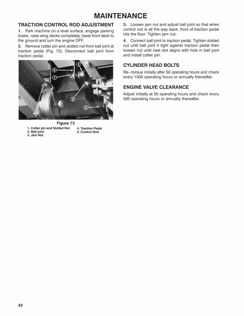
42
MAINTENANCETRACTION CONTROL ROD ADJUSTMENT
1. Park machine on a level surface, engage parkingbrake, raise wing decks completely, lower front deck tothe ground and turn the engine OFF.
2. Remove cotter pin and slotted nut from ball joint at
traction pedal (Fig. 73). Disconnect ball joint fromtraction pedal.
Figure 731. Cotter pin and Slotted Nut2. Ball joint3. Jam Nut
4. Traction Pedal5. Control Rod
3. Loosen jam nut and adjust ball joint so that whencontrol rod is all the way back, front of traction pedalhits the floor. Tighten jam nut.
4. Connect ball joint to traction pedal. Tighten slottednut until ball joint it tight against traction pedal then
loosen nut until next slot aligns with hole in ball jointand install cotter pin.
CYLINDER HEAD BOLTS
Re-torque initially after 50 operating hours and checkevery 1000 operating hours or annually thereafter.
ENGINE VALVE CLEARANCE
Adjust initially at 50 operating hours and check every500 operating hours or annually thereafter.

43
ELECTRICAL SCHEMATIC
T-1668
ALARM
FUEL SENDER
WATER IN FUEL
ENGINE TEMP.
AUDIO ALARM
OIL FILTER PLUGGED
GROUND
YELLOW/RED
AIR CLEANER
NO.
BLUE
ORANGE
GREEN/WHITE
TAN
PINKHYD. OIL LOW
OIL TEMP. SWITCH
INPUT POWERFROM CONTROLLER
AUDIO ALARM
OIL PRESSURE SWITCH
VOLTMETER
1
2
3
4
5
6
7
8
9
10
16
17
18
19
20
21
22
23
24
11
12
13
14
15
2
3
4
6
7
8
16
17
18
19
21
24
13
14
24
2015
9
4
1
51016
21
PIN
WHITE
BLACK
BROWN
BROWN/RED
RED/WHITE
GREEN/RED
YELLOW
PURPLE
SWITCH
ENG. COOLANT TEMP.
12V +
AUDIO
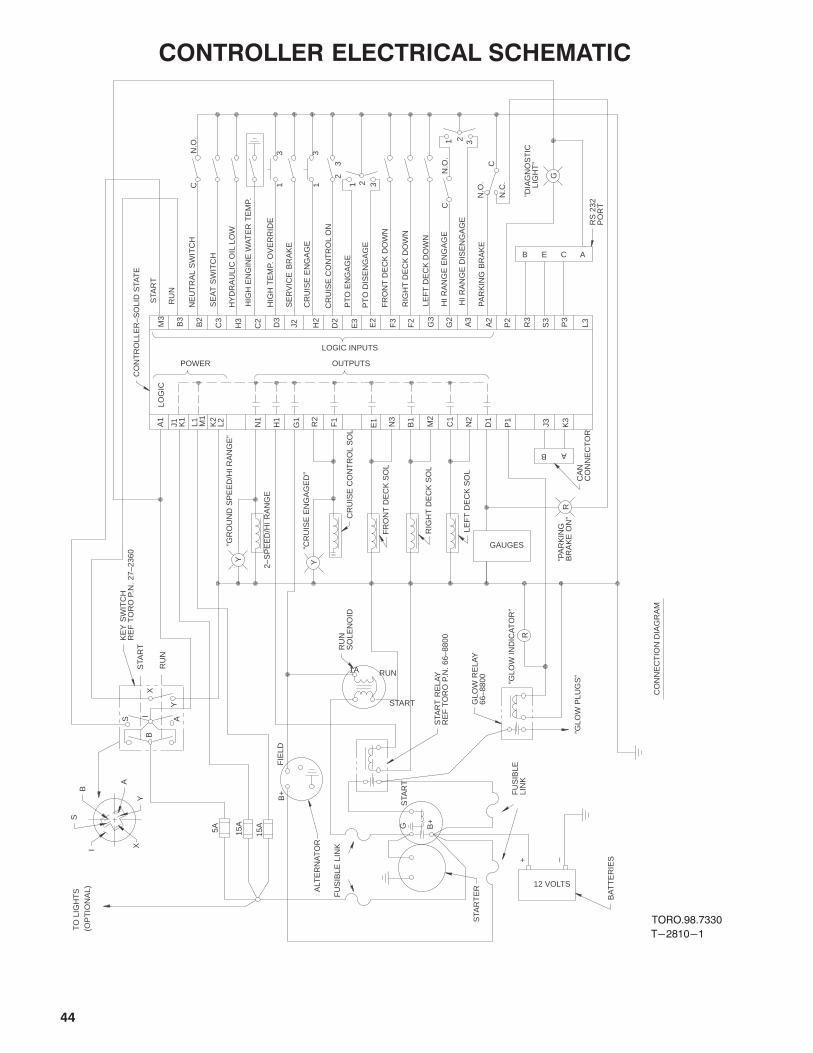
44
CONTROLLER ELECTRICAL SCHEMATIC
T-2810-1
TORO.98.7330
GLO
W R
ELA
Y66
–880
0
X
STA
RT
RE
LAY
RE
F T
OR
O P
.N.
66–8
800KE
Y S
WIT
CH
RE
F T
OR
O P
.N.
27–2
360
LEF
T D
EC
K S
OL
FR
ON
T D
EC
K S
OL
RU
NS
OLE
NO
ID
Y
A
BS
I
ALT
ER
NA
TO
R
STA
RT
ER
BA
TT
ER
IES
CR
UIS
E C
ON
TR
OL
SO
L
RIG
HT
DE
CK
SO
L
CA
N
CO
NN
EC
TO
RR
S 2
32
PO
RT
CO
NT
RO
LLE
R–S
OLI
D S
TAT
E
B+ F
US
IBLE
LIN
K
(OP
TIO
NA
L)
”GLO
W P
LUG
S”
R
P1
CN
.O.
G
ACE
B+
P3
S3
L3R3
P2
J3 K3
N2
M2
N3
R2
LOG
IC
OUTPUTSPOWER
LOGIC INPUTS
CO
NN
EC
TIO
N D
IAG
RA
M
GAUGES”CR
UIS
E E
NG
AG
ED
”
”GR
OU
ND
SP
EE
D/H
I RA
NG
E”
2–S
PE
ED
/HI
RA
NG
E
”PA
RK
ING
BR
AK
E O
N”
A1
J1 K1
K2
L2L1 M1
3 311C
N.O
.
CN
.C.
N.O
.
HI R
AN
GE
DIS
EN
GA
GE
PT
O D
ISE
NG
AG
E
PT
O E
NG
AG
E3
2
321
321
B A
1A
START
RUN
15A
15A
5A
TO
LIG
HT
S
RU
N
STA
RT
B
S AI
Y
X
Y
FIE
LD
”GLO
W IN
DIC
AT
OR
”+ –
12 VOLTS
Y
”DIA
GN
OS
TIC
L
IGH
T”
B
G
FU
SIB
LE L
INK
STA
RT
R
HI R
AN
GE
EN
GA
GE
PA
RK
ING
BR
AK
E
LEF
T D
EC
K D
OW
N
RIG
HT
DE
CK
DO
WN
FR
ON
T D
EC
K D
OW
N
CR
UIS
E C
ON
TR
OL
ON
CR
UIS
E E
NG
AG
E
SE
RV
ICE
BR
AK
E
HIG
H T
EM
P. O
VE
RR
IDE
HY
DR
AU
LIC
OIL
LO
W
SE
AT
SW
ITC
H
NE
UT
RA
L S
WIT
CH
RU
N
HIG
H E
NG
INE
WA
TE
R T
EM
P.
STA
RT
D1
C1
B1
E1F1
G1
H1
N1
A3
G2
A2
G3
F2
F3
E2
E3
D2
H2
J2D3
C2
H3
C3
B2
B3
M3
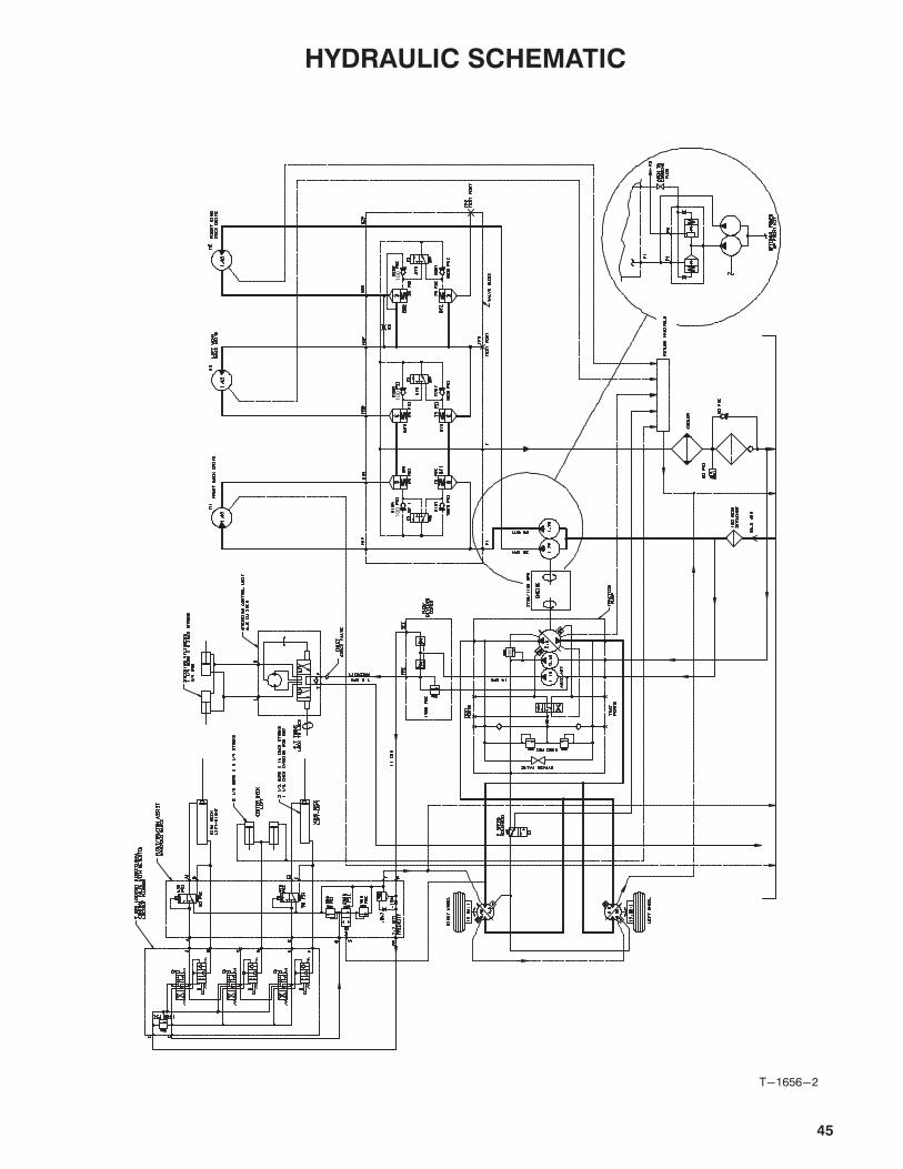
45
HYDRAULIC SCHEMATIC
T-1656-2
10
01
00
28
5
10
0

46
MAINTENANCE SCHEDULE
Minimum Recommended Maintenance Intervals
Maintenance Procedure
Lubricate All Grease Fittings
Inspect Air Filter, Dust Cup, and Baffle
Clean Under Cutting Unit Belt Covers
Check Cutting Unit Drive Belt Adjustment
� Change Engine Oil and Replace Filter
� Check Fan and Alternator Belt Tension
Inspect Cooling System Hoses
Service Air Filter
Replace Fuel/Water Separator Filter
� Torque Wheel Lug Nuts
Check Battery Level/Cable Connections
� Replace Hydraulic Filter
� Torque Head and Adjust Valves
� Check Engine RPM (idle and full throttle)
� Change Planetary Gear Drive Fluid
Check Rear Wheel Toe-In
� Initial break in at 10 hours
� Initial break in at 50 hours
Change Brake Fluid
Change Fuel Filter
Change Thermostat
Replace Safety Switches
Flush Cooling System and Replace Hoses
Fuel Tank- Drain/Flush
Change Hydraulic Oil
Every50hrs
Every100hrs
Every200hrs
Every800hrs
Maintenance Interval & Service
Annual Recommendations:Items listed are recommended every 1000hours or 2 years, whichever occurs first.
Every400hrs

47
PRODUCT IDENTIFICATION
MODEL AND SERIAL NUMBERS
A plate containing two identification numbers, a modeland serial number, is affixed to the traction unit on theleft bulkhead below the operator's seat and on the rearchannel of each cutting unit. In correspondence
regarding the machine, supply the model and serialnumber to assure correct information and replacementparts are obtained.
To order parts from an authorized TORO Distributor,please provide:
1. Model and serial numbers of the component inquestion.
2. Part number, description and quantity of parts
desired.
Note: Do not order by reference number. If a partscatalog is being used, use the part number.
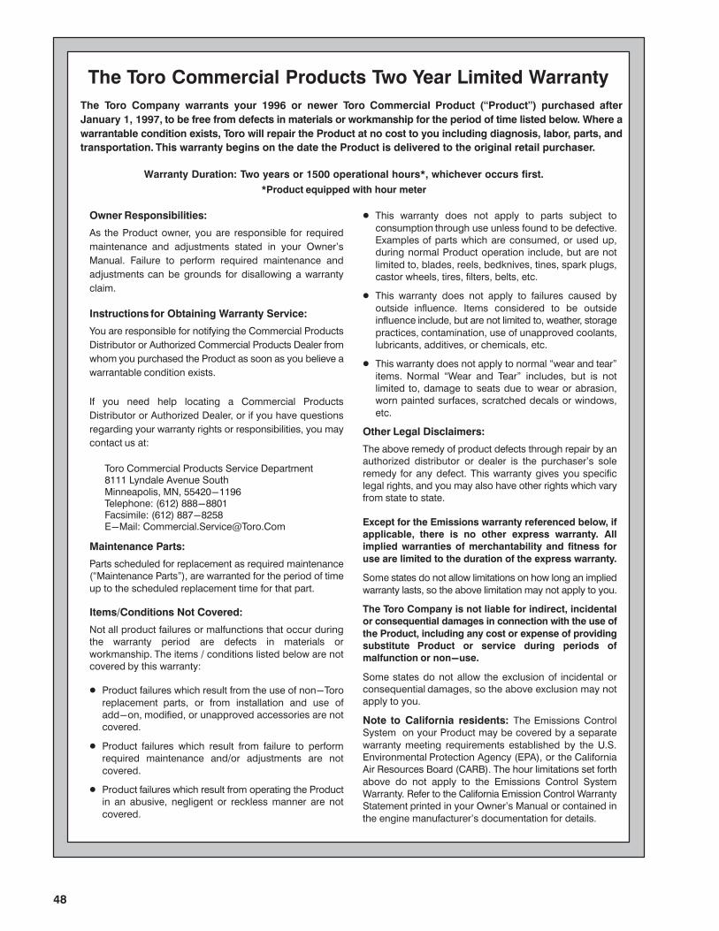
48
Owner Responsibilities:
As the Product owner, you are responsible for required
maintenance and adjustments stated in your Owner's
Manual. Failure to perform required maintenance and
adjustments can be grounds for disallowing a warranty
claim.
Instructions for Obtaining Warranty Service:
You are responsible for notifying the Commercial Products
Distributor or Authorized Commercial Products Dealer from
whom you purchased the Product as soon as you believe a
warrantable condition exists.
If you need help locating a Commercial Products
Distributor or Authorized Dealer, or if you have questions
regarding your warranty rights or responsibilities, you may
contact us at:
Toro Commercial Products Service Department8111 Lyndale Avenue SouthMinneapolis, MN, 55420-1196Telephone: (612) 888-8801Facsimile: (612) 887-8258E-Mail: [email protected]
Maintenance Parts:
Parts scheduled for replacement as required maintenance(�Maintenance Parts"), are warranted for the period of time
up to the scheduled replacement time for that part.
Items/Conditions Not Covered:
Not all product failures or malfunctions that occur duringthe warranty period are defects in materials or
workmanship. The items / conditions listed below are notcovered by this warranty:
� Product failures which result from the use of non-Toro
replacement parts, or from installation and use ofadd-on, modified, or unapproved accessories are notcovered.
� Product failures which result from failure to performrequired maintenance and/or adjustments are not
covered.
� Product failures which result from operating the Productin an abusive, negligent or reckless manner are not
covered.
The Toro Company warrants your 1996 or newer Toro Commercial Product (�Product") purchased after
January 1, 1997, to be free from defects in materials or workmanship for the period of time listed below. Where a
warrantable condition exists, Toro will repair the Product at no cost to you including diagnosis, labor, parts, and
transportation. This warranty begins on the date the Product is delivered to the original retail purchaser.
Warranty Duration: Two years or 1500 operational hours*, whichever occurs first.
*Product equipped with hour meter
� This warranty does not apply to parts subject to
consumption through use unless found to be defective.Examples of parts which are consumed, or used up,during normal Product operation include, but are not
limited to, blades, reels, bedknives, tines, spark plugs,castor wheels, tires, filters, belts, etc.
� This warranty does not apply to failures caused by
outside influence. Items considered to be outsideinfluence include, but are not limited to, weather, storage
practices, contamination, use of unapproved coolants,lubricants, additives, or chemicals, etc.
� This warranty does not apply to normal �wear and tear"
items. Normal �Wear and Tear" includes, but is notlimited to, damage to seats due to wear or abrasion,worn painted surfaces, scratched decals or windows,
etc.
Other Legal Disclaimers:
The above remedy of product defects through repair by anauthorized distributor or dealer is the purchaser's sole
remedy for any defect. This warranty gives you specificlegal rights, and you may also have other rights which varyfrom state to state.
Except for the Emissions warranty referenced below, if
applicable, there is no other express warranty. All
implied warranties of merchantability and fitness for
use are limited to the duration of the express warranty.
Some states do not allow limitations on how long an implied
warranty lasts, so the above limitation may not apply to you.
The Toro Company is not liable for indirect, incidental
or consequential damages in connection with the use of
the Product, including any cost or expense of providing
substitute Product or service during periods of
malfunction or non-use.
Some states do not allow the exclusion of incidental orconsequential damages, so the above exclusion may notapply to you.
Note to California residents: The Emissions ControlSystem on your Product may be covered by a separate
warranty meeting requirements established by the U.S.Environmental Protection Agency (EPA), or the CaliforniaAir Resources Board (CARB). The hour limitations set forth
above do not apply to the Emissions Control SystemWarranty. Refer to the California Emission Control WarrantyStatement printed in your Owner's Manual or contained in
the engine manufacturer's documentation for details.
The Toro Commercial Products Two Year Limited Warranty
Related Documents