BG 20 Großdrehbohrgerät Rotary Drilling Rig Geräteträger BT 60 Base Carrier BT 60 6/2008

Welcome message from author
This document is posted to help you gain knowledge. Please leave a comment to let me know what you think about it! Share it to your friends and learn new things together.
Transcript
BG 20GroßdrehbohrgerätRotary Drilling Rig
Geräteträger BT 60Base Carrier BT 60
6/2008
905-635-1_6-08 BG20.qxd 01.07.2008 12:19 Uhr Seite 1
BG 20 (BT 60) – Großdrehbohrgerät BG 20 (BT 60) – Rotary Drilling Rig
1000
12410
18870
20860
8610
7570
4160
360
0
Hub / S
troke 8
250 m
m
Kelly
BK
20/3
68/3
/21 (
A=
9400 m
m)
84
00
3200 3300
5600
4685
12
00
85
00
Abmessungen Dimensions
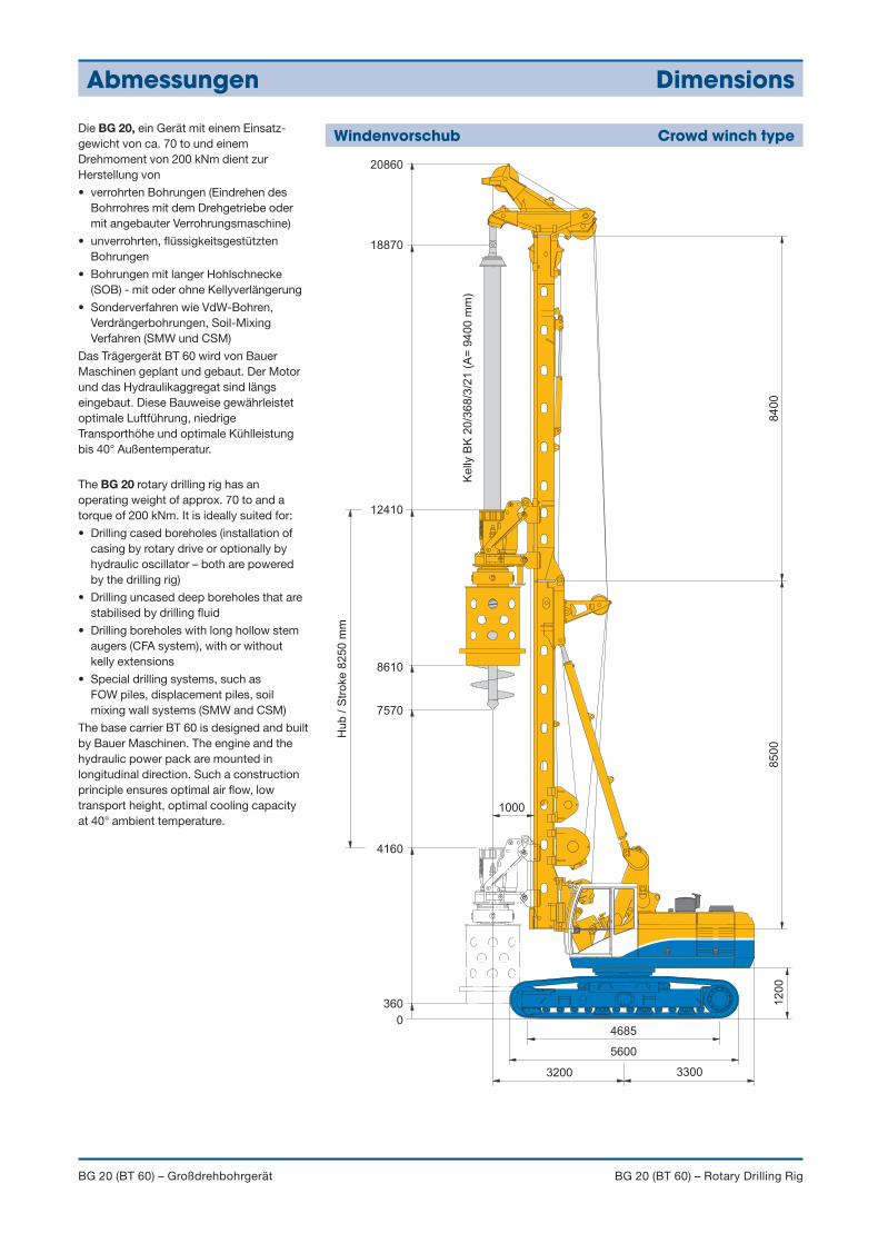
Windenvorschub Crowd winch typeDie BG 20, ein Gerät mit einem Einsatz-gewicht von ca. 70 to und einemDrehmoment von 200 kNm dient zurHerstellung von
• verrohrten Bohrungen (Eindrehen desBohrrohres mit dem Drehgetriebe odermit angebauter Verrohrungsmaschine)
• unverrohrten, flüssigkeitsgestütztenBohrungen
• Bohrungen mit langer Hohlschnecke(SOB) - mit oder ohne Kellyverlängerung
• Sonderverfahren wie VdW-Bohren,Verdrängerbohrungen, Soil-MixingVerfahren (SMW und CSM)
Das Trägergerät BT 60 wird von BauerMaschinen geplant und gebaut. Der Motorund das Hydraulikaggregat sind längseingebaut. Diese Bauweise gewährleistetoptimale Luftführung, niedrigeTransporthöhe und optimale Kühlleistungbis 40° Außentemperatur.
The BG 20 rotary drilling rig has anoperating weight of approx. 70 to and atorque of 200 kNm. It is ideally suited for:
• Drilling cased boreholes (installation ofcasing by rotary drive or optionally byhydraulic oscillator – both are poweredby the drilling rig)
• Drilling uncased deep boreholes that arestabilised by drilling fluid
• Drilling boreholes with long hollow stemaugers (CFA system), with or withoutkelly extensions
• Special drilling systems, such as FOW piles, displacement piles, soilmixing wall systems (SMW and CSM)
The base carrier BT 60 is designed and builtby Bauer Maschinen. The engine and thehydraulic power pack are mounted inlongitudinal direction. Such a constructionprinciple ensures optimal air flow, lowtransport height, optimal cooling capacityat 40° ambient temperature.
905-635-1_6-08 BG20.qxd 01.07.2008 12:19 Uhr Seite 2
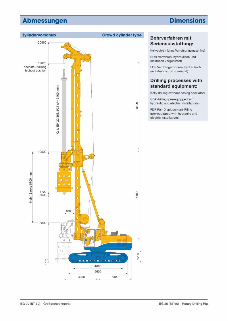
Bohrverfahren mitSerienausstattung:Kellybohren (ohne Verrohrungsmaschine)
SOB-Verfahren (hydraulisch undelektrisch vorgerüstet)
FDP Verdrängerbohren (hydraulischund elektrisch vorgerüstet)
Drilling processes withstandard equipment:Kelly drilling (without casing oscillator)
CFA drilling (pre-equipped withhydraulic and electric installations)
FDP Full-Displacement-Piling(pre-equipped with hydraulic andelectric installations)
Abmessungen Dimensions
BG 20 (BT 60) – Großdrehbohrgerät BG 20 (BT 60) – Rotary Drilling Rig
1000
10500
18870
höchste Stellung
highest position
20860
67006500
3800
70
Hub / S
troke 6
700 m
m
Kelly
BK
20/3
68/3
/21 (
A=
9400 m
m)
84
00
3200 3300
5600
4685
12
00
85
00
Zylindervorschub Crowd cylinder type
905-635-1_6-08 BG20.qxd 01.07.2008 12:19 Uhr Seite 3
Technische Daten Technical specifications
BG 20 (BT 60) – Großdrehbohrgerät BG 20 (BT 60) – Rotary Drilling Rig
Windenvorschub ZylindervorschubCrowd Winch Crowd Cylinder
Gesamthöhe Overall height 20.860 mm 20.860 mm
Einsatzgewicht ca. Operating weight (approx.)(mit Kelly BK 20/368/3/21) (with kelly BK 20/368/3/21) 65.000 kg 65.000 kg
Drehantrieb Rotary Drive KDK 200 K KDK 200 K
Drehmoment bei 300 bar (nom.) Torque at 300 bar (nominal) 200 kNm 200 kNm
Drehzahl max Speed of rotation (max.) 35 U/min (RPM) 35 U/min (RPM)
Vorschubsystem Crowd system
Druckkraft / Zugkraft (effektiv) Crowd force push / pull (effective) 260 kN / 260 kN 200 kN / 260 kN
Druckkraft / Zugkraft Crowd force push / pull gemessen am Drehteller KDK measured at the casing drive adapter 205 kN / 210 kN 205 kN / 210 kN
Hub (Kellysystem) Stroke (kelly system) 8.250 mm 6.700 mm
Hub (SOB-System) Stroke (CFA system) 14.000 mm 13.650 mm
Geschwindigkeit (ab/auf) Speed (down/up) 7,0 / 7,0 m/min 5,0 / 7,0 m/min
Schnellgang (ab/auf) Fast speed (down/up) 25 / 25 m/min 20 / 20 m/min
Hauptwinde Main winch
Windenklasse Winch classification M6 / L3 / T5 M6 / L3 / T5
Zugkraft (1. Lage) effektiv/nominal Line pull ( 1st layer) effective/nominal 170 kN / 218 kN 170 kN / 218 kN
Seildurchmesser / Länge Rope diameter / length 26 mm / 66 m 26 mm / 66 m
Windengeschwindigkeit Line speed max. 56 m/min 56 m/min
Hilfswinde Auxiliary winch
Windenklasse Winch classification M6 / L3 / T5 M6 / L3 / T5
Zugkraft (1. Lage) effektiv/nominal Line pull (1st layer) effective/nominal 55 kN / 70 kN 55 kN / 70 kN
Seildurchmesser / Länge Rope diameter / length 15 mm / 50 m 15 mm / 50 m
Windengeschwindigkeit Line speed (max.) 90 m/min 90 m/min
Mastneigung Mast inclination
nach hinten / vorne / quer Backward / forward / lateral 15° / 5° / 5° 15° / 5° / 5°
Serienausstattung Standard equipment
• Drehgetriebe KDK 200 K (Konstantgetriebe)
• Hauptwinde mit hydraulischer Freilaufsteuerung
• Haupt- und Hilfswinde mit Spezialrillung
• Hubendschalter für Haupt- und Hilfswinde
• Vorschub schnell / langsam
• Wirbel für Hauptseil
• Schwenkbarer Anschlagpunkt für Haupt- und Hilfsseil
• Transportstützen für Mastoberteil und Mastunterteil
Mess- und Steuerungstechnik• SPS Rechner für alle elektrisch angesteuerten Funktionen
• Bauer Standardbildschirmeinheit inkl. Diagnosefunktion
• Analoge Anzeige der Pumpendrücke (3 Manometer)
• Anzeige von Fehlermeldungen
• Notsteuerung Bohrgerät (Kernfunktionen)
• Mastneigungsmessung in x/y Richtung (Anzeige digital/ analog)
• Mastautomatik (automatische Vertikalstellung)
• Hilfswinde mit hydraulischer Seilkraftmessung
• Tiefenmessung Hauptwinde
• Tiefenmessung Vorschub (bei Windenvorschub)
• Rotary drive KDK 200 K (single gear drive)
• Main winch with hydraulically operated freewheeling
• Main and auxiliary winch with special grooving
• Hoist limit switch on main and auxiliary winches
• Crowd in fast or slow mode
• Swivel for main rope
• Pivoted anchor points for main and auxiliary ropes
• Transport supports for upper and lower mast sections
Measuring and control equipment• PLC processor for all electrically actuated functions
• Standard monitor unit with integrated diagnostic capability
• Analog display of pump pressures (3 pressure gauges)
• Display of fault messages
• Emergency mode of operation for drilling rig (core functions)
• Mast inclination measurement on x/y axes (digital/analog display)
• Automatic vertical alignment of mast
• Hydraulic load sensing on auxiliary rope
• Depth measuring device on main winch
• Depth measuring device (on crowd winch)
905-635-1_6-08 BG20.qxd 01.07.2008 12:19 Uhr Seite 4
Drehgetriebe Rotary drive
BG 20 (BT 60) – Großdrehbohrgerät BG 20 (BT 60) – Rotary Drilling Rig
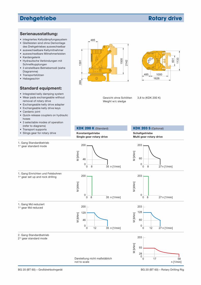
Serienausstattung:• integriertes Kellydämpfungssystem• Gleitleisten sind ohne Demontage
des Drehgetriebes auswechselbar• auswechselbare Kellymitnehmer• auswechselbare Mitnehmerleisten• Kardangelenk• Hydraulische Verbindungen mit
Schnellkupplungen• 3 einstellbare Betriebsmodi (siehe
Diagramme)• Transportstützen• Hebegeschirr
Standard equipment:• Integrated kelly damping system• Wear pads exchangeable without
removal of rotary drive• Exchangeable kelly drive adapter• Exchangeable kelly drive keys• Cardanic joint• Quick-release couplers on hydraulic
hoses• 3 selectable modes of operation
(refer to diagrams)• Transport supports• Slings gear for rotary drive
420
60
1
11
33
1000
1626
485
15
00
26
91
39
1
485
21
42
Gewicht ohne Schlitten 3,8 to (KDK 200 K)Weight w/c sledge
200
M [kN
m] 129
00 12 35
200
M [kN
m]
00 8 35
200
M [kN
m]
n [1/min]
n [1/min]
n [1/min]
46
46
00 8 35
203
M [kN
m]
n [1/min]
93
280
0 17 58
203
M [kN
m] 128
00 12 27
203
M [kN
m]
00 8 27
203
M [kN
m]
n [1/min]
n [1/min]
n [1/min]
60
60
00 8 27
1. Gang Standardbetrieb1st gear standard mode
Darstellung nicht maßstäblichnot to scale
1. Gang Einrichten und Felsbohren1st gear set up and rock drilling
1. Gang Md reduziert1st gear Md reduced
2. Gang Standardbetrieb2nd gear standard mode
KonstantgetriebeSingle gear rotary drive
KDK 200 K (Standard) KDK 203 S (Optional)
SchaltgetriebeMulti gear rotary drive
905-635-1_6-08 BG20.qxd 01.07.2008 12:19 Uhr Seite 5
Geräteträger BT 60 Base carrier BT 60
BG 20 (BT 60) – Großdrehbohrgerät BG 20 (BT 60) – Rotary Drilling Rig
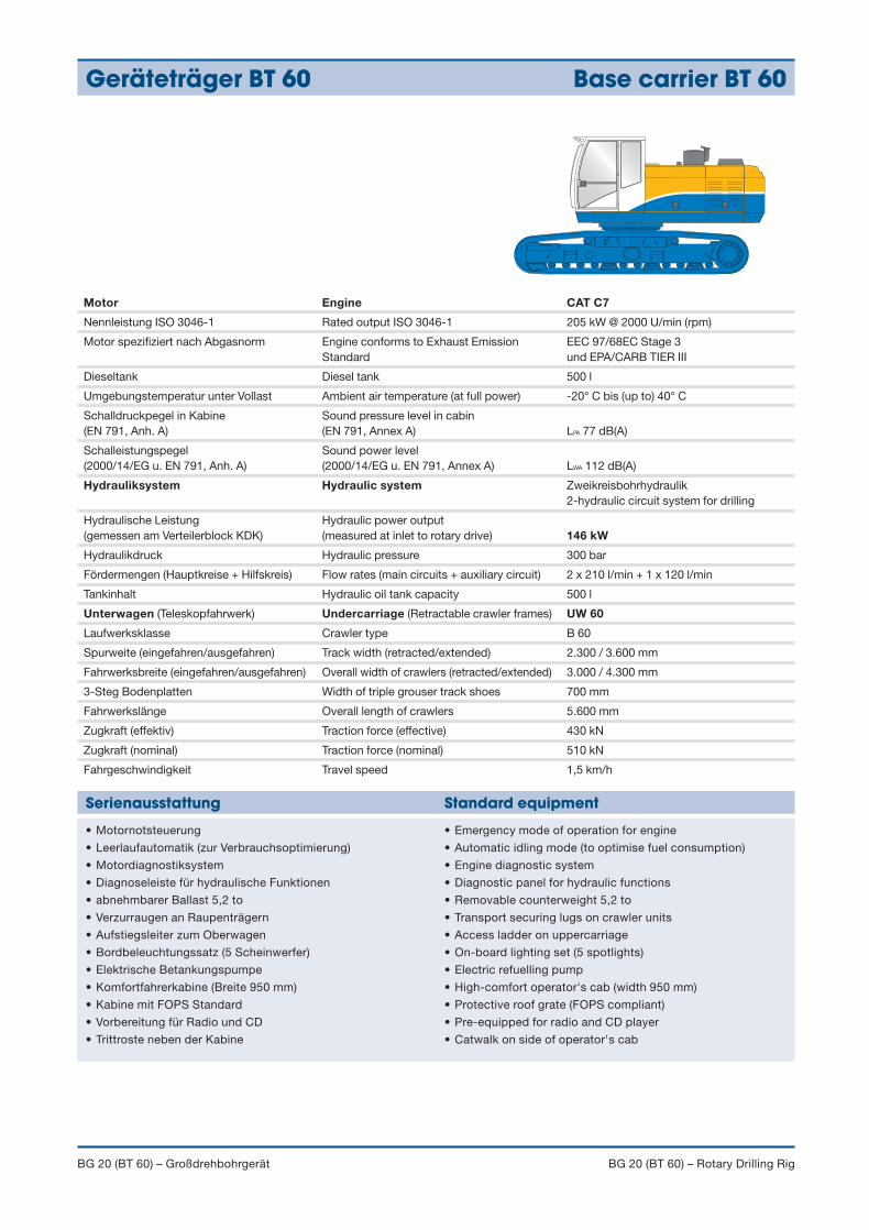
Motor Engine CAT C7
Nennleistung ISO 3046-1 Rated output ISO 3046-1 205 kW @ 2000 U/min (rpm)
Motor spezifiziert nach Abgasnorm Engine conforms to Exhaust Emission EEC 97/68EC Stage 3Standard und EPA/CARB TIER III
Dieseltank Diesel tank 500 l
Umgebungstemperatur unter Vollast Ambient air temperature (at full power) -20° C bis (up to) 40° C
Schalldruckpegel in Kabine Sound pressure level in cabin(EN 791, Anh. A) (EN 791, Annex A) LPA 77 dB(A)
Schalleistungspegel Sound power level (2000/14/EG u. EN 791, Anh. A) (2000/14/EG u. EN 791, Annex A) LWA 112 dB(A)
Hydrauliksystem Hydraulic system Zweikreisbohrhydraulik2-hydraulic circuit system for drilling
Hydraulische Leistung Hydraulic power output(gemessen am Verteilerblock KDK) (measured at inlet to rotary drive) 146 kW
Hydraulikdruck Hydraulic pressure 300 bar
Fördermengen (Hauptkreise + Hilfskreis) Flow rates (main circuits + auxiliary circuit) 2 x 210 l/min + 1 x 120 l/min
Tankinhalt Hydraulic oil tank capacity 500 l
Unterwagen (Teleskopfahrwerk) Undercarriage (Retractable crawler frames) UW 60
Laufwerksklasse Crawler type B 60
Spurweite (eingefahren/ausgefahren) Track width (retracted/extended) 2.300 / 3.600 mm
Fahrwerksbreite (eingefahren/ausgefahren) Overall width of crawlers (retracted/extended) 3.000 / 4.300 mm
3-Steg Bodenplatten Width of triple grouser track shoes 700 mm
Fahrwerkslänge Overall length of crawlers 5.600 mm
Zugkraft (effektiv) Traction force (effective) 430 kN
Zugkraft (nominal) Traction force (nominal) 510 kN
Fahrgeschwindigkeit Travel speed 1,5 km/h
• Motornotsteuerung
• Leerlaufautomatik (zur Verbrauchsoptimierung)
• Motordiagnostiksystem
• Diagnoseleiste für hydraulische Funktionen
• abnehmbarer Ballast 5,2 to
• Verzurraugen an Raupenträgern
• Aufstiegsleiter zum Oberwagen
• Bordbeleuchtungssatz (5 Scheinwerfer)
• Elektrische Betankungspumpe
• Komfortfahrerkabine (Breite 950 mm)
• Kabine mit FOPS Standard
• Vorbereitung für Radio und CD
• Trittroste neben der Kabine
• Emergency mode of operation for engine
• Automatic idling mode (to optimise fuel consumption)
• Engine diagnostic system
• Diagnostic panel for hydraulic functions
• Removable counterweight 5,2 to
• Transport securing lugs on crawler units
• Access ladder on uppercarriage
• On-board lighting set (5 spotlights)
• Electric refuelling pump
• High-comfort operator's cab (width 950 mm)
• Protective roof grate (FOPS compliant)
• Pre-equipped for radio and CD player
• Catwalk on side of operator's cab
Serienausstattung Standard equipment
905-635-1_6-08 BG20.qxd 01.07.2008 12:19 Uhr Seite 6
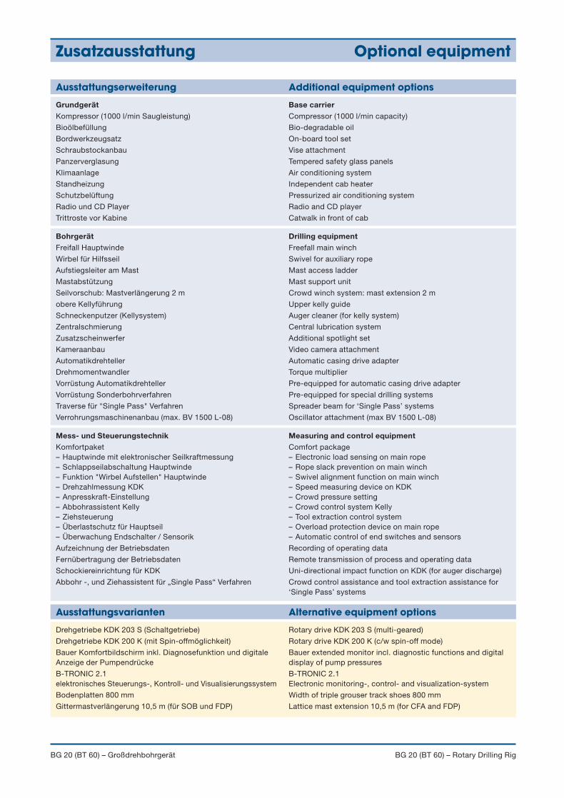
Drehgetriebe KDK 203 S (Schaltgetriebe)
Drehgetriebe KDK 200 K (mit Spin-offmöglichkeit)
Bauer Komfortbildschirm inkl. Diagnosefunktion und digitaleAnzeige der Pumpendrücke
B-TRONIC 2.1 elektronisches Steuerungs-, Kontroll- und Visualisierungssystem
Bodenplatten 800 mm
Gittermastverlängerung 10,5 m (für SOB und FDP)
Rotary drive KDK 203 S (multi-geared)
Rotary drive KDK 200 K (c/w spin-off mode)
Bauer extended monitor incl. diagnostic functions and digitaldisplay of pump pressures
B-TRONIC 2.1Electronic monitoring-, control- and visualization-system
Width of triple grouser track shoes 800 mm
Lattice mast extension 10,5 m (for CFA and FDP)
Ausstattungsvarianten Alternative equipment options
Zusatzausstattung Optional equipment
BG 20 (BT 60) – Großdrehbohrgerät BG 20 (BT 60) – Rotary Drilling Rig
Ausstattungserweiterung Additional equipment options
GrundgerätKompressor (1000 l/min Saugleistung)
Bioölbefüllung
Bordwerkzeugsatz
Schraubstockanbau
Panzerverglasung
Klimaanlage
Standheizung
Schutzbelüftung
Radio und CD Player
Trittroste vor Kabine
Base carrierCompressor (1000 l/min capacity)
Bio-degradable oil
On-board tool set
Vise attachment
Tempered safety glass panels
Air conditioning system
Independent cab heater
Pressurized air conditioning system
Radio and CD player
Catwalk in front of cab
BohrgerätFreifall Hauptwinde
Wirbel für Hilfsseil
Aufstiegsleiter am Mast
Mastabstützung
Seilvorschub: Mastverlängerung 2 m
obere Kellyführung
Schneckenputzer (Kellysystem)
Zentralschmierung
Zusatzscheinwerfer
Kameraanbau
Automatikdrehteller
Drehmomentwandler
Vorrüstung Automatikdrehteller
Vorrüstung Sonderbohrverfahren
Traverse für "Single Pass" Verfahren
Verrohrungsmaschinenanbau (max. BV 1500 L-08)
Drilling equipmentFreefall main winch
Swivel for auxiliary rope
Mast access ladder
Mast support unit
Crowd winch system: mast extension 2 m
Upper kelly guide
Auger cleaner (for kelly system)
Central lubrication system
Additional spotlight set
Video camera attachment
Automatic casing drive adapter
Torque multiplier
Pre-equipped for automatic casing drive adapter
Pre-equipped for special drilling systems
Spreader beam for ‘Single Pass’ systems
Oscillator attachment (max BV 1500 L-08)
Mess- und SteuerungstechnikKomfortpaket– Hauptwinde mit elektronischer Seilkraftmessung– Schlappseilabschaltung Hauptwinde– Funktion "Wirbel Aufstellen" Hauptwinde– Drehzahlmessung KDK – Anpresskraft-Einstellung – Abbohrassistent Kelly– Ziehsteuerung– Überlastschutz für Hauptseil– Überwachung Endschalter / Sensorik
Aufzeichnung der Betriebsdaten
Fernübertragung der Betriebsdaten
Schockiereinrichtung für KDK
Abbohr -, und Ziehassistent für „Single Pass“ Verfahren
Measuring and control equipmentComfort package– Electronic load sensing on main rope– Rope slack prevention on main winch– Swivel alignment function on main winch– Speed measuring device on KDK– Crowd pressure setting – Crowd control system Kelly– Tool extraction control system– Overload protection device on main rope– Automatic control of end switches and sensors
Recording of operating data
Remote transmission of process and operating data
Uni-directional impact function on KDK (for auger discharge)
Crowd control assistance and tool extraction assistance for‘Single Pass’ systems
905-635-1_6-08 BG20.qxd 01.07.2008 12:19 Uhr Seite 7
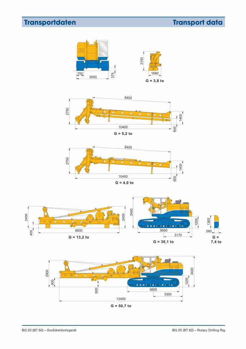
Transportdaten Transport data
BG 20 (BT 60) – Großdrehbohrgerät BG 20 (BT 60) – Rotary Drilling Rig
3400
12
00
3300
60
0 5600
13400
90
0
29
00
21
40
13
65
5600
3170
1680
3400
12
00
580
2400
8800
2400
400
60
0
1400
8400
27
50
104006
00
1400
8400
27
50
10400
37
5
3000700
G =
7,4 to
G = 3,8 to
G = 5,2 to
G = 4,0 to
G = 13,2 to
G = 30,1 to
G = 50,7 to
905-635-1_6-08 BG20.qxd 01.07.2008 12:19 Uhr Seite 8
Anwendungen Applications
BG 20 (BT 60) – Großdrehbohrgerät BG 20 (BT 60) – Rotary Drilling Rig
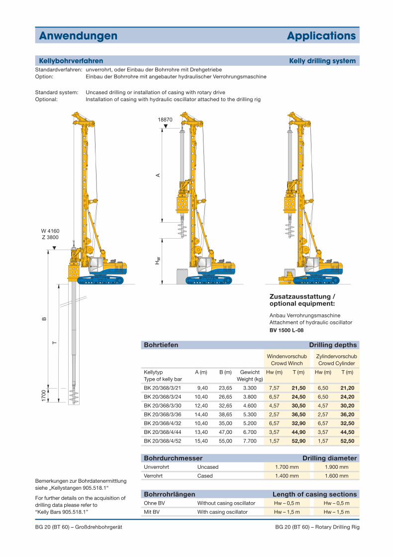
Kellybohrverfahren Kelly drilling system
W 4160
Z 3800
17
00
A
B
T
Hw
18870
Bemerkungen zur Bohrdatenermittlungsiehe „Kellystangen 905.518.1“
For further details on the acquisition ofdrilling data please refer to “Kelly Bars 905.518.1”
Unverrohrt Uncased 1.700 mm 1.900 mm
Verrohrt Cased 1.400 mm 1.600 mm
Bohrdurchmesser Drilling diameter
Ohne BV Without casing oscillator Hw – 0,5 m Hw – 0,5 m
Mit BV With casing oscillator Hw – 1,5 m Hw – 1,5 m
Bohrrohrlängen Length of casing sections
Bohrtiefen Drilling depths
Zusatzausstattung / optional equipment:
Anbau VerrohrungsmaschineAttachment of hydraulic oscillator
BV 1500 L-08
Standardverfahren: unverrohrt, oder Einbau der Bohrrohre mit DrehgetriebeOption: Einbau der Bohrrohre mit angebauter hydraulischer Verrohrungsmaschine
Standard system: Uncased drilling or installation of casing with rotary driveOptional: Installation of casing with hydraulic oscillator attached to the drilling rig
Windenvorschub ZylindervorschubCrowd Winch Crowd Cylinder
Kellytyp A (m) B (m) Gewicht Hw (m) T (m) Hw (m) T (m)Type of kelly bar Weight (kg)
BK 20/368/3/21 9,40 23,65 3.300 7,57 21,50 6,50 21,20
BK 20/368/3/24 10,40 26,65 3.800 6,57 24,50 6,50 24,20
BK 20/368/3/30 12,40 32,65 4.600 4,57 30,50 4,57 30,20
BK 20/368/3/36 14,40 38,65 5.300 2,57 36,50 2,57 36,20
BK 20/368/4/32 10,40 35,00 5.200 6,57 32,90 6,57 32,50
BK 20/368/4/44 13,40 47,00 6.700 3,57 44,90 3,57 44,50
BK 20/368/4/52 15,40 55,00 7.700 1,57 52,90 1,57 52,50
905-635-1_6-08 BG20.qxd 01.07.2008 12:19 Uhr Seite 9
Anwendungen Applications
BG 20 (BT 60) – Großdrehbohrgerät BG 20 (BT 60) – Rotary Drilling Rig
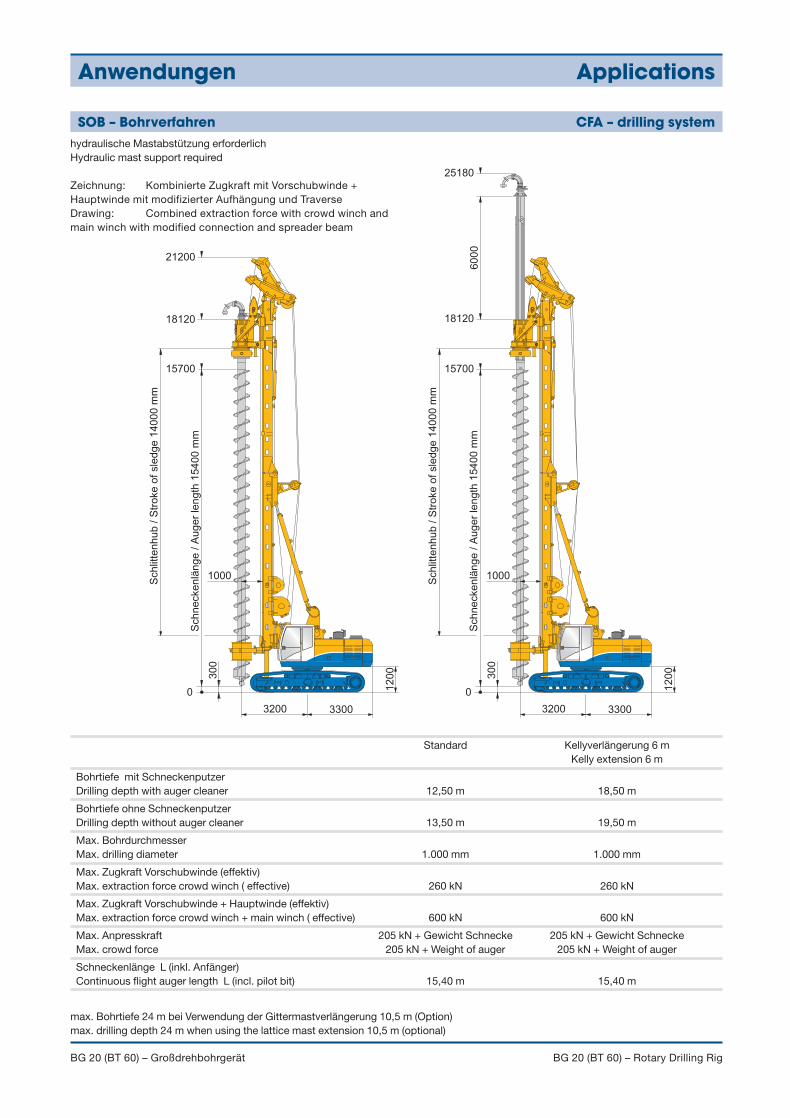
SOB – Bohrverfahren CFA – drilling system
1000
3200 3300
12
00
6000
0
30
0
21200
18120
15700
Sch
ne
cke
nlä
ng
e /
Au
ge
r le
ng
th 1
54
00
mm
Schlit
tenhub / S
troke o
f sle
dge 1
4000 m
m
1000
3200 3300
12
00
0
30
0
25180
18120
15700
Sch
ne
cke
nlä
ng
e /
Au
ge
r le
ng
th 1
54
00
mm
Schlit
tenhub / S
troke o
f sle
dge 1
4000 m
m
hydraulische Mastabstützung erforderlichHydraulic mast support required
Zeichnung: Kombinierte Zugkraft mit Vorschubwinde +Hauptwinde mit modifizierter Aufhängung und Traverse Drawing: Combined extraction force with crowd winch andmain winch with modified connection and spreader beam
Standard Kellyverlängerung 6 mKelly extension 6 m
Bohrtiefe mit SchneckenputzerDrilling depth with auger cleaner 12,50 m 18,50 m
Bohrtiefe ohne SchneckenputzerDrilling depth without auger cleaner 13,50 m 19,50 m
Max. BohrdurchmesserMax. drilling diameter 1.000 mm 1.000 mm
Max. Zugkraft Vorschubwinde (effektiv)Max. extraction force crowd winch ( effective) 260 kN 260 kN
Max. Zugkraft Vorschubwinde + Hauptwinde (effektiv)Max. extraction force crowd winch + main winch ( effective) 600 kN 600 kN
Max. Anpresskraft 205 kN + Gewicht Schnecke 205 kN + Gewicht SchneckeMax. crowd force 205 kN + Weight of auger 205 kN + Weight of auger
Schneckenlänge L (inkl. Anfänger)Continuous flight auger length L (incl. pilot bit) 15,40 m 15,40 m
max. Bohrtiefe 24 m bei Verwendung der Gittermastverlängerung 10,5 m (Option)max. drilling depth 24 m when using the lattice mast extension 10,5 m (optional)
905-635-1_6-08 BG20.qxd 01.07.2008 12:19 Uhr Seite 10
Anwendungen Applications
BG 20 (BT 60) – Großdrehbohrgerät BG 20 (BT 60) – Rotary Drilling Rig
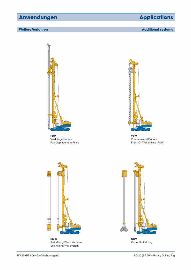
Weitere Verfahren Additional systems
FDPVerdrängerbohrenFull Displacement Piling
VdWVor-der-Wand BohrenFront-Of-Wall drilling (FOW)
SMWSoil Mixing Wand VerfahrenSoil Mixing Wall system
CSMCutter Soil Mixing
905-635-1_6-08 BG20.qxd 01.07.2008 12:19 Uhr Seite 11
Technical Specifications are subject to change withoutprior notice and incurring responsibility for machinespreviously sold. The shown machines may have specialequipment. Technical data do not consider power losses.Error and misprints reserved.
Technische Änderungen ohne Vorankündigung undVerpflichtung gegenüber früher gelieferten Geräten. Die abgebildeten Geräte können Sonderausstattungenhaben. Technische Daten ohne Berücksichtigung desWirkungsgrades.Irrtum und Druckfehler vorbehalten. 905.635.1 6/08
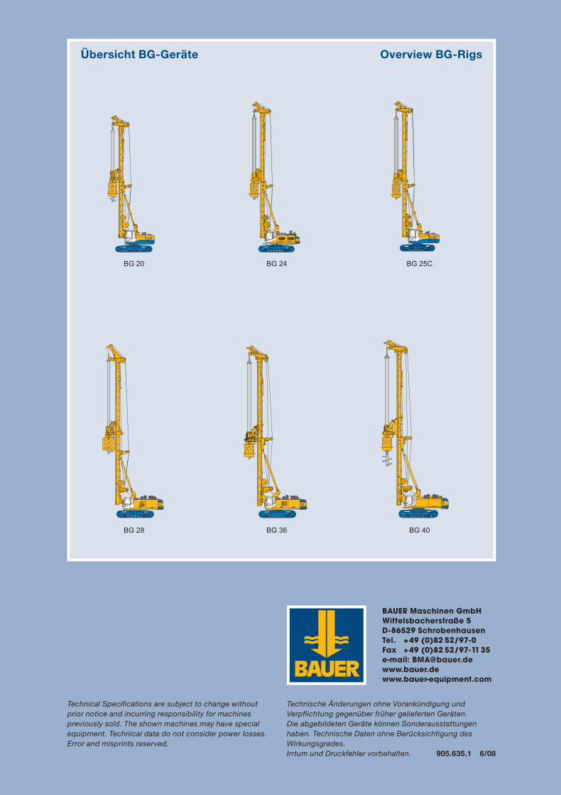
Übersicht BG-Geräte Overview BG-Rigs
BAUER Maschinen GmbHWittelsbacherstraße 5D-86529 SchrobenhausenTel. +49 (0)82 52/97-0Fax +49 (0)82 52/97-1135e-mail: [email protected]
BG 40BG 36BG 28
BG 25CBG 24BG 20
905-635-1_6-08 BG20.qxd 01.07.2008 12:19 Uhr Seite 12
Related Documents