Gridbus Workflow Management System and Aneka Enterprise Middleware A project on the integration of the two technologies by Dileban Karunamoorthy Submitted in partial fulfillment of the requirements of the course Masters of Engineering in Distributed Computing at The department of Computer Science and Software Engineering University of Melbourne June 2009 Supervised by Dr. Rajkumar Buyya

Welcome message from author
This document is posted to help you gain knowledge. Please leave a comment to let me know what you think about it! Share it to your friends and learn new things together.
Transcript
Gridbus Workflow Management System
and
Aneka Enterprise Middleware
A project on the integration of the two technologies
by
Dileban Karunamoorthy
Submitted in partial fulfillment of the requirements of the course
Masters of Engineering in Distributed Computing
at
The department of Computer Science and Software Engineering
University of Melbourne
June 2009
Supervised by Dr. Rajkumar Buyya
Integration of Gridbus Workflow Management System with Aneka Enterprise Middleware
1
Dileban Karunamoorthy, Distributed Computing Project, 2009
Abstract
The Gridbus Workflow Management System is an environment for realizing scientific
workflows on computational and data grids. The workflow engine, based on an event driven
scheduling architecture using tuple spaces along with just-in-time scheduling, allows for the
creation and execution of complex workflows on grids that is both scalable and fault-tolerant.
The provision of a workflow language facilitates in the definition of scientific workflows. An
important component underlying the workflow engine is the Gridbus Broker, a resource
broker for managing the execution of independent jobs on heterogeneous environments.
Aneka is a platform independent, enterprise grid and cloud computing middleware for
building and deploying parallel data and compute intensive applications. Aneka is both a
development and execution environment supporting multiple programming models. The file-
based task model provides a coarse-grained abstraction and is ideal for parameter-sweep
applications and grid-enabling legacy applications. Tasks are independent units of work whose
results must be collated by clients.
The requirement for integrating both these technologies is the seamless execution of
workflow tasks on Aneka. Abstract tasks, ordered by any dependency relations, must be
translated into independent concrete task instances for consumption by Aneka. All
communication relating to initiation, monitoring and termination must be bridged between
the two technologies. Resources required for task execution must be staged in and the results
staged out. The solution must also keep to the goals of fault-tolerance and scalability. This
report presents the study, design and implementation on the integration of the Gridbus
Workflow Management System with Aneka.
Keywords: Grid Computing, Cloud Computing, Workflow Management, Aneka

Integration of Gridbus Workflow Management System with Aneka Enterprise Middleware
2
Dileban Karunamoorthy, Distributed Computing Project, 2009
Acknowledgements
A project of this nature, requiring a clear understanding of the different technologies involved along
with their design and implementation decisions within a short time span, is by no means easy. This is
particularly so when the technologies involved are the result of years of research and development.
Reading past research papers and other documentation, and reviewing code and design diagrams
don’t present a complete picture, particularly when decisions made are not clear or when some of
the documentation is incomplete. Feedback from past engineers, researchers and peers thus
become invaluable and resourceful. This is so not just for this project undertaken, but also for the
many projects I’ve worked on in the past.
I would like to begin by thanking my supervisor, Dr. Rajkumar Buyya, who oversaw the progress of
this project and constantly provided positive feedback and guidance during my reporting. The series
of discussions we had on the project, its aim and objectives, over the past few months set the tone
for the entire project.
I would also like to thank Suraj Pandey with whom I worked with over the past several months as
part of the larger SCALE 2009 project. Suraj has extensive experience with the Gridbus Workflow
Management System, and his input on its design and implementation proved invaluable to this
project. We also spent several hours, including many late nights, solving illusive problems, testing
and meeting deadlines. His support all along is highly appreciated.
Dr. Christian Vecchiola and XingChen Chu with whom I worked with for nearly 6 months on Aneka,
have provided all the advice I needed on the required changes for the integration. Their input on the
pros and cons on different approaches, alternative design choices, and useful tips on undertaking
projects of this nature were invaluable.
This work was partially funded by the Australia Research Council (ARC) and the Department of
Innovation, Industry, Science and Research (DIISR). I also thank GRIDS Lab for the opportunity to
work in the capacity of a research assistant for the past six months.
Integration of Gridbus Workflow Management System with Aneka Enterprise Middleware
3
Dileban Karunamoorthy, Distributed Computing Project, 2009
TABLE OF CONTENTS
Chapter 1 - Introduction
1.1 INTRODUCTION ................................................................................................................................... 7
1.2 PROJECT BACKGROUND ...................................................................................................................... 7
1.3 AIM ..................................................................................................................................................... 8
1.4 OBJECTIVES ......................................................................................................................................... 8
1.5 MOTIVATION....................................................................................................................................... 8
1.6 SUMMARY .......................................................................................................................................... 9
Chapter 2 - Technology Review
2.1 INTRODUCTION ................................................................................................................................. 11
2.2 THE GRIDBUS WORKFLOW MANAGEMENT SYSTEM .......................................................................... 11
2.2.1 GRIDBUS WORKFLOW ENGINE (GWFE) ....................................................................................................... 12
Workflow Scheduling ................................................................................................................................... 13
2.3 THE GRIDBUS BROKER ....................................................................................................................... 14
2.3.1 THE PLUGIN ARCHITECTURE ....................................................................................................................... 15
2.4 ANEKA ............................................................................................................................................... 16
2.4.1 PROGRAMMING MODELS .......................................................................................................................... 18
The Task Programming Model ..................................................................................................................... 18
Thread Programming Model ........................................................................................................................ 18
MapReduce Programming Model ................................................................................................................ 18
2.4.2 ANEKA SERVICES ...................................................................................................................................... 18
Scheduling Service ........................................................................................................................................ 19
Storage Service ............................................................................................................................................. 19
Execution Service.......................................................................................................................................... 19
2.5 SUMMARY ........................................................................................................................................ 19
Chapter 3 - Design
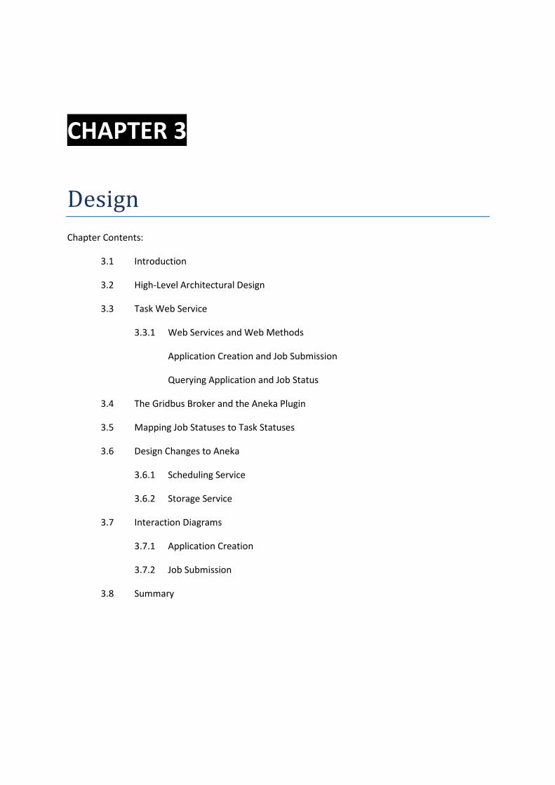
3.1 INTRODUCTION ................................................................................................................................. 21
3.2 HIGH-LEVEL ARCHITECTURAL DESIGN ................................................................................................ 21
3.3 TASK WEB SERVICE ............................................................................................................................ 23
3.3.1 WEB SERVICES AND WEB METHODS ............................................................................................................ 23
Application Creation and Job Submission .................................................................................................... 24
Querying Application and Job Status ........................................................................................................... 25
3.4 THE GRIDBUS BROKER AND THE ANEKA PLUGIN ............................................................................... 26
3.5 MAPPING JOB STATUSES TO TASK STATUSES .................................................................................... 29
3.6 DESIGN CHANGES TO ANEKA ............................................................................................................. 29
3.6.1 SCHEDULING SERVICE ................................................................................................................................ 29
3.6.2 STORAGE SERVICE .................................................................................................................................... 30
Integration of Gridbus Workflow Management System with Aneka Enterprise Middleware
4
Dileban Karunamoorthy, Distributed Computing Project, 2009
3.7 INTERACTION DIAGRAMS .................................................................................................................. 34
3.7.1 APPLICATION CREATION ............................................................................................................................ 34
3.7.2 JOB SUBMISSION ...................................................................................................................................... 35
3.8 SUMMARY ........................................................................................................................................ 36
Chapter 4 - Implementation
4.1 INTRODUCTION ................................................................................................................................. 38
4.2 TASK WEB SERVICE ............................................................................................................................ 38
4.2.1 ALTERNATIVE APPROACHES ........................................................................................................................ 39
A Stateful Approach ..................................................................................................................................... 39
A Stateless Approach using “BindApplication” ............................................................................................ 39
A Stateless Approach using TaskManagerHelper ........................................................................................ 39
4.3 SCHEDULING AND STORAGE SERVICES .............................................................................................. 39
4.4 ANEKA PLUGIN FOR GRIDBUS BROKER .............................................................................................. 41
4.4.1 APACHE XMLBEANS VS APACHE AXIS 2 ....................................................................................................... 41
4.5 ISSUES AND BUGS DISCOVERED ........................................................................................................ 42
4.6 SUMMARY ........................................................................................................................................ 42
Chapter 5 - Testing
5.1 INTRODUCTION ................................................................................................................................. 44
5.2 UNIT TESTS ........................................................................................................................................ 44
5.3 INTEGRATION AND VERIFICATION TESTING ON AMAZON ................................................................. 44
5.3.1 INSTALLATION AND CONFIGURATION ............................................................................................................ 44
5.3.2 TEST CASE .............................................................................................................................................. 45
5.3.3 EXECUTION AND RESULTS .......................................................................................................................... 46
5.4 ANALYSIS........................................................................................................................................... 48
5.5 SUMMARY ........................................................................................................................................ 49
Chapter 6 - Conclusion and Future Work
6.1 CONCLUSION ..................................................................................................................................... 51
6.2 FUTURE WORK .................................................................................................................................. 51
REFERENCES………………………………………………………………………………………………………………………………...… 53
Integration of Gridbus Workflow Management System with Aneka Enterprise Middleware
5
Dileban Karunamoorthy, Distributed Computing Project, 2009
TABLE OF FIGURES
Figure 1 - The architecture of the Gridbus Workflow Management System ....................................... 11
Figure 2 - Activity and data flow during a typical workflow execution ................................................ 12
Figure 3 - The event-driven architecture of the Gridbus Workflow Engine ......................................... 13
Figure 4 - The Gridbus Broker Architecture .......................................................................................... 15
Figure 5 - The Plugin Architecture ........................................................................................................ 16
Figure 6 - The Aneka Enterprise Cloud Architecture ............................................................................ 17
Figure 7 - The Aneka Container Architecture ....................................................................................... 17
Figure 8 - Integrating the Workflow Management System with Aneka Enterprise Cloud ................... 21
Figure 9 - The class diagram for the TaskService, the core component of the Task Web Service ....... 23
Figure 10 - Information exchanged during Application Creation and Job Submission ......................... 24
Figure 11 - Definition of a Job ............................................................................................................... 24
Figure 12 - The class hierarchy representing the types of pre-defined Tasks ...................................... 25
Figure 13 - Application and Job Statuses .............................................................................................. 26
Figure 14 - The AnekaComputeServer and dependent classes for interacting with the Task Web S... 27
Figure 15 - The AnekaJobWrapper and dependent classes for interacting with the Task Web Serv ... 28
Figure 16 - The abstract class WorkUnit ............................................................................................... 30
Figure 17 - The Storage Service and File Transfer Messages ................................................................ 31
Figure 18 - Controller and handler interfaces for file transfers ............................................................ 32
Figure 19 - Implementation of the controller and handler interfaces for file transfers based on F .... 33
Figure 20 - Interaction diagram show the creation of an application .................................................. 34
Figure 21 - Sequence diagram showing the process of submitting jobs .............................................. 35
Figure 22 - ASP.Net implementation of the Task Web Service ............................................................. 38
Figure 23 - Code snippet showing an example of the communication between the Scheduling Se .... 40
Figure 24 - Code Snippet for the message handler for remote file transfers in the Storage Service ... 40
Figure 25 - Code snippet showing the creation of an application using Axis 2 .................................... 41
Figure 26 - Code snippet showing the submission a job using Axis 2 ................................................... 42
Figure 27 - GWMS and Aneka Enterprise Cloud setup on Amazon EC2 ............................................... 45
Figure 28 - Workflow Monitoring Graph for EMO ................................................................................ 46
Figure 29 - Workflow Monitoring Table for EMO ................................................................................. 46
Figure 30 - Portion of performance graph showing 94% of the collective CPU power of 42 GHz in ... 47
Figure 31 - Plot for 2-Obtective Function ............................................................................................. 48
CHAPTER 1
Introduction
Chapter Contents:
1.1 Introduction
1.2 Project Background
1.3 Aim
1.4 Objectives
1.5 Motivation
1.6 Summary
Integration of Gridbus Workflow Management System with Aneka Enterprise Middleware
7
Dileban Karunamoorthy, Distributed Computing Project, 2009
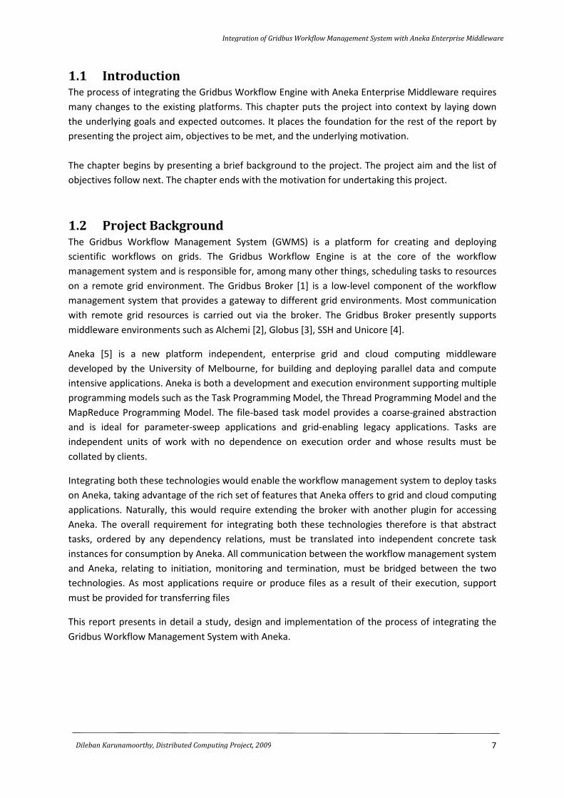
1.1 Introduction The process of integrating the Gridbus Workflow Engine with Aneka Enterprise Middleware requires
many changes to the existing platforms. This chapter puts the project into context by laying down
the underlying goals and expected outcomes. It places the foundation for the rest of the report by
presenting the project aim, objectives to be met, and the underlying motivation.
The chapter begins by presenting a brief background to the project. The project aim and the list of
objectives follow next. The chapter ends with the motivation for undertaking this project.
1.2 Project Background The Gridbus Workflow Management System (GWMS) is a platform for creating and deploying
scientific workflows on grids. The Gridbus Workflow Engine is at the core of the workflow
management system and is responsible for, among many other things, scheduling tasks to resources
on a remote grid environment. The Gridbus Broker [1] is a low-level component of the workflow
management system that provides a gateway to different grid environments. Most communication
with remote grid resources is carried out via the broker. The Gridbus Broker presently supports
middleware environments such as Alchemi [2], Globus [3], SSH and Unicore [4].
Aneka [5] is a new platform independent, enterprise grid and cloud computing middleware
developed by the University of Melbourne, for building and deploying parallel data and compute
intensive applications. Aneka is both a development and execution environment supporting multiple
programming models such as the Task Programming Model, the Thread Programming Model and the
MapReduce Programming Model. The file-based task model provides a coarse-grained abstraction
and is ideal for parameter-sweep applications and grid-enabling legacy applications. Tasks are
independent units of work with no dependence on execution order and whose results must be
collated by clients.
Integrating both these technologies would enable the workflow management system to deploy tasks
on Aneka, taking advantage of the rich set of features that Aneka offers to grid and cloud computing
applications. Naturally, this would require extending the broker with another plugin for accessing
Aneka. The overall requirement for integrating both these technologies therefore is that abstract
tasks, ordered by any dependency relations, must be translated into independent concrete task
instances for consumption by Aneka. All communication between the workflow management system
and Aneka, relating to initiation, monitoring and termination, must be bridged between the two
technologies. As most applications require or produce files as a result of their execution, support
must be provided for transferring files
This report presents in detail a study, design and implementation of the process of integrating the
Gridbus Workflow Management System with Aneka.
Integration of Gridbus Workflow Management System with Aneka Enterprise Middleware
8
Dileban Karunamoorthy, Distributed Computing Project, 2009
1.3 Aim
“The seamless integration of the Gridbus Workflow Management System with Aneka Enterprise
Middleware, enabling the execution of complex workflows on a grid driven by Aneka “
1.4 Objectives The project objectives provide general guidelines and important milestones for completing the
project. The following are the list of objectives set out for the project.
� Carryout a comprehensive literature and technology study on the essential components of
the Gridbus Workflow Management and Aneka. These include:
- Gridbus Workflow Engine
- The Gridbus Broker
- The plugin architecture of the Gridbus Broker
- Aneka’s Scheduling Service
- Aneka’s Storage Service
- Current file transfer mechanism used within Ankea
� Carryout high-level design changes to the existing infrastructure of the Gridbus Workflow
Management System, the Gridbus Broker and Aneka.
� Carryout a detailed low-level design on new components and changes to existing
components in the Workflow Engine, broker and Aneka.
� Translate the design specification into implementation. The required implementation for the
different technologies will be carried out using the appropriate languages, development
environments, and tools.
� Test and debug the solution. This requires defining a suitable test strategy and using a real-
life application to determine whether the overall project aims have been met.
1.5 Motivation
The primary motivation for undertaking this project was the SCALE 2009 challenge at CCGrid09, a
conference for cluster and grid computing. The goal was to demonstrate a series of workflow
applications deployed on Aneka middleware. Another important reason for pursuing this project lies
in the advantages brought about as a result of integrating the Gridbus Workflow Management
System with a comprehensive grid and cloud computing platform such as Aneka. Aneka is both a
development and execution environment, supporting multiple programming models. Integrating the
two technologies would enable users to take advantage of the rich set of features Aneka has to
offer, through the workflow management system.
Integration of Gridbus Workflow Management System with Aneka Enterprise Middleware
9
Dileban Karunamoorthy, Distributed Computing Project, 2009
1.6 Summary
This chapter laid the foundation for the rest of the report. It began by presenting an overview of the
project in which the Gridbus Workflow Management System and Aneka were discussed briefly, with
the aim of highlighting the need for integrating the two technologies. This was followed by the aims
and objectives for the project. The chapter concluded with a brief note on the motivations behind
the project. The next chapter will delve into the first objective – a detailed study on the different
technologies involved.
CHAPTER 2
Technology Review
Chapter Contents:
2.1 Introduction
2.2 The Gridbus Workflow Management System
2.2.1 Gridbus Workflow Engine (Gwfe)
Workflow Scheduling
2.3 The Gridbus Broker
2.3.1 The Plugin Architecture
2.4 Aneka
2.4.1 Programming Models
The Task Programming Model
Thread Programming Model
Mapreduce Programming Model
2.4.2 Aneka Services
Scheduling Service
Storage Service
Execution Service
2.5 Summary
Integration of Gridbus Workflow Management System with Aneka Enterprise Middleware
11
Dileban Karunamoorthy, Distributed Computing Project, 2009
2.1 Introduction The purpose of this chapter is to discuss the salient features of the different technologies involved.
In doing, this chapter hopes to draw the reader’s attention to those features that will be frequently
talked about in the rest of the report. This includes the functioning of the Gridbus Workflow Engine
and its relationship to the Gridbus Broker. A closer look at the Gridbus Broker is essential in order to
understand the architecture and mechanisms involved in communicating with a wide array of
middleware, including Aneka. Naturally, we will then look at Aneka, its architecture and key services
that will be affected in order to bring about this integration.
The chapter begins by presenting a high-level view of the Gridbus Workflow Management System
(GWMS), focusing primarily on the Gridbus Workflow Engine (GWFE). This is followed by a discussion
on the Gridbus Broker (GBB) and the essential components that help in communicating with remote
resources. The chapter ends with a detailed discussion on Aneka.
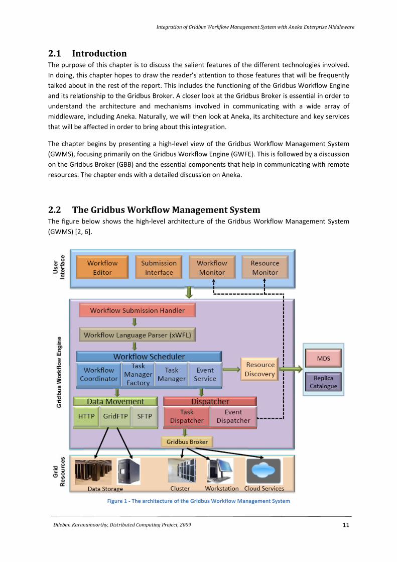
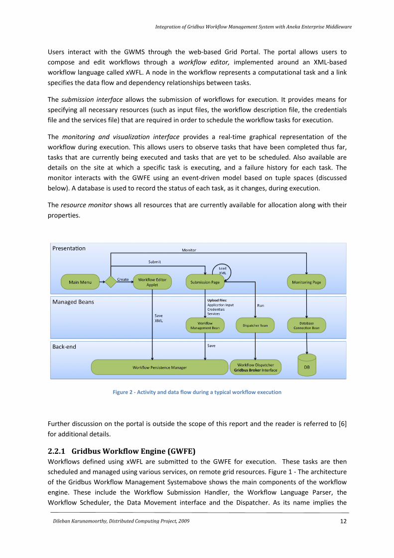
2.2 The Gridbus Workflow Management System The figure below shows the high-level architecture of the Gridbus Workflow Management System
(GWMS) [2, 6].
Figure 1 - The architecture of the Gridbus Workflow Management System
Integration of Gridbus Workflow Management System with Aneka Enterprise Middleware
12
Dileban Karunamoorthy, Distributed Computing Project, 2009
Users interact with the GWMS through the web-based Grid Portal. The portal allows users to
compose and edit workflows through a workflow editor, implemented around an XML-based
workflow language called xWFL. A node in the workflow represents a computational task and a link
specifies the data flow and dependency relationships between tasks.
The submission interface allows the submission of workflows for execution. It provides means for
specifying all necessary resources (such as input files, the workflow description file, the credentials
file and the services file) that are required in order to schedule the workflow tasks for execution.
The monitoring and visualization interface provides a real-time graphical representation of the
workflow during execution. This allows users to observe tasks that have been completed thus far,
tasks that are currently being executed and tasks that are yet to be scheduled. Also available are
details on the site at which a specific task is executing, and a failure history for each task. The
monitor interacts with the GWFE using an event-driven model based on tuple spaces (discussed
below). A database is used to record the status of each task, as it changes, during execution.
The resource monitor shows all resources that are currently available for allocation along with their
properties.
Figure 2 - Activity and data flow during a typical workflow execution
Further discussion on the portal is outside the scope of this report and the reader is referred to [6]
for additional details.
2.2.1 Gridbus Workflow Engine (GWFE)
Workflows defined using xWFL are submitted to the GWFE for execution. These tasks are then
scheduled and managed using various services, on remote grid resources. Figure 1 - The architecture
of the Gridbus Workflow Management Systemabove shows the main components of the workflow
engine. These include the Workflow Submission Handler, the Workflow Language Parser, the
Workflow Scheduler, the Data Movement interface and the Dispatcher. As its name implies the
Integration of Gridbus Workflow Management System with Aneka Enterprise Middleware
13
Dileban Karunamoorthy, Distributed Computing Project, 2009
Workflow Submission Handler handles workflows submitted via the portal, which is then passed on
to the Workflow Language Parser. The Workflow Language Parser converts workflows defined in the
XML-based xWFL language into artifacts such as “tasks”, “parameters”, “data constraints”
(workflow/task dependencies), and “conditions”, for processing by the scheduler. The resource
discovery service is used to query Grid Information Services (GIS) such as the Globus MDS, directory
catalogs and replica catalogs, in order to identify suitable resources for executing the workflow
tasks, by coordinating with the Gridbus Broker. The Gridbus Broker (discussed in more detail below)
mediates access to the different resources on behalf of the workflow engine. It provides middleware
specific plugins to bridge communication between different remote middleware technologies. In
general, it is responsible for deploying tasks on remote services, transferring data to and from the
resources, monitoring task execution and collating the results. The Data Movement component
facilitates the transfer of data between the workflow engine and remote resources using protocols
such as SFTP and GridFTP. The Resource Discovery component helps in the discovery of suitable
resources for task assignment. The workflow engine also provides mechanisms for specifying the
location of temporary data. Task failures are typically handled by resubmitting tasks to resources
without a significant failure history.
Workflow Scheduling
The Workflow Scheduler is central to scheduling tasks on remote resources. Due to the dynamic and
unreliable nature of grid resources, scheduling decisions for task execution must ideally be made as
late as possible. The workflow engine supports just-in-time scheduling where decisions are made at
runtime as and when tasks are executed. This allows for choosing the best resources for task
execution, based on resource information available at runtime.
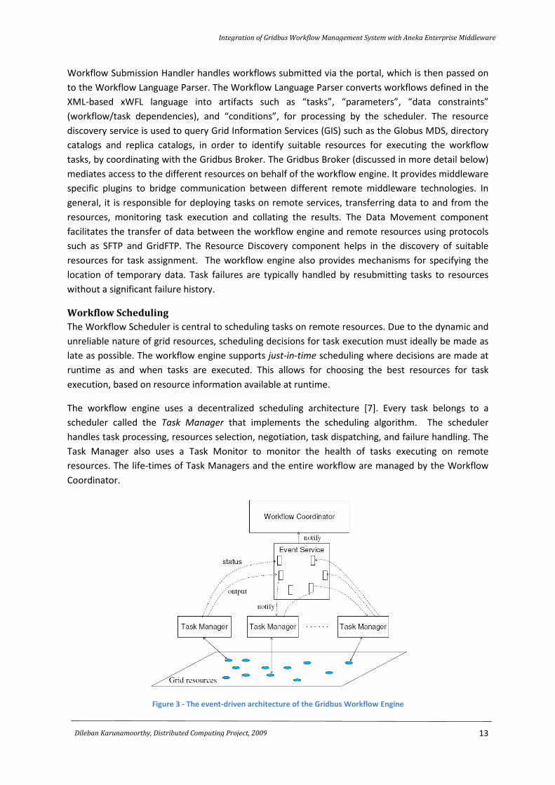
The workflow engine uses a decentralized scheduling architecture [7]. Every task belongs to a
scheduler called the Task Manager that implements the scheduling algorithm. The scheduler
handles task processing, resources selection, negotiation, task dispatching, and failure handling. The
Task Manager also uses a Task Monitor to monitor the health of tasks executing on remote
resources. The life-times of Task Managers and the entire workflow are managed by the Workflow
Coordinator.
Figure 3 - The event-driven architecture of the Gridbus Workflow Engine
Integration of Gridbus Workflow Management System with Aneka Enterprise Middleware
14
Dileban Karunamoorthy, Distributed Computing Project, 2009
Figure 3 above shows the event-driven architecture of the workflow engine. The Workflow
Coordinator managing the entire workflow execution and the decentralized Task Managers
communicate via the Event Service. The Task Managers may be independent and run in parallel, or
may depend on other Task Managers as a result of task dependencies in the workflow.
The Event Service is based on tuple spaces as defined in the Linda Coordination Model [8]. The
particular implementation used in the workflow engine is IBM’s TSpaces [9]. The Event Service uses
the subscribe-notify idiom for communication, enabling just-in-time scheduling. The Workflow
Coordinator and the collection of Task Managers avoid communicating directly with each other and
instead generate or listen to events of interest. When an event of interest occurs, all subscribed
listeners will be notified. This decouples the listeners from each other providing a flexible design.
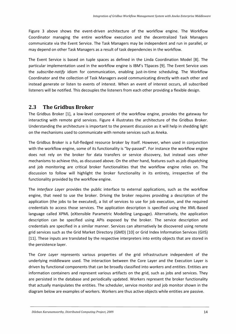
2.3 The Gridbus Broker The Gridbus Broker [1], a low-level component of the workflow engine, provides the gateway for
interacting with remote grid services. Figure 4 illustrates the architecture of the Gridbus Broker.
Understanding the architecture is important to the present discussion as it will help in shedding light
on the mechanisms used to communicate with remote services such as Aneka.
The Gridbus Broker is a full-fledged resource broker by itself. However, when used in conjunction
with the workflow engine, some of its functionality is “by-passed”. For instance the workflow engine
does not rely on the broker for data transfers or service discovery, but instead uses other
mechanisms to achieve this, as discussed above. On the other hand, features such as job dispatching
and job monitoring are critical broker functionalities that the workflow engine relies on. The
discussion to follow will highlight the broker functionality in its entirety, irrespective of the
functionality provided by the workflow engine.
The Interface Layer provides the public interface to external applications, such as the workflow
engine, that need to use the broker. Driving the broker requires providing a description of the
application (the jobs to be executed), a list of services to use for job execution, and the required
credentials to access those services. The application description is specified using the XML-Based
language called XPML (eXtensible Parametric Modelling Language). Alternatively, the application
description can be specified using APIs exposed by the broker. The service description and
credentials are specified in a similar manner. Services can alternatively be discovered using remote
grid services such as the Grid Market Directory (GMD) [10] or Grid Index Information Services (GIIS)
[11]. These inputs are translated by the respective interpreters into entity objects that are stored in
the persistence layer.
The Core Layer represents various properties of the grid infrastructure independent of the
underlying middleware used. The interaction between the Core Layer and the Execution Layer is
driven by functional components that can be broadly classified into workers and entities. Entities are
information containers and represent various artifacts on the grid, such as jobs and services. They
are persisted in the database and periodically updated. Workers represent the broker functionality
that actually manipulates the entities. The scheduler, service monitor and job monitor shown in the
diagram below are examples of workers. Workers are thus active objects while entities are passive.
Integration of Gridbus Workflow Management System with Aneka Enterprise Middleware
15
Dileban Karunamoorthy, Distributed Computing Project, 2009
Figure 4 - The Gridbus Broker Architecture
The Execution Layer is responsible for dispatching jobs to remote middleware services for execution.
The jobs must typically be translated into middleware-specific objects for consumption. Various
middleware plugins are used to bridge the communication with remote services. The Gridbus Broker
provides a number of such plugins pre-built, such as plugins for Aneka, Alchemi, Globus, Ssh and
Unicore. During execution, the Job Monitor keeps track of the job statuses (i.e. queued, executing,
completed successfully or failed) on the remote resource. On job completion, the associated agent
on the remote resource returns any results back to the broker, and provides additional debugging
information in case of job failure.
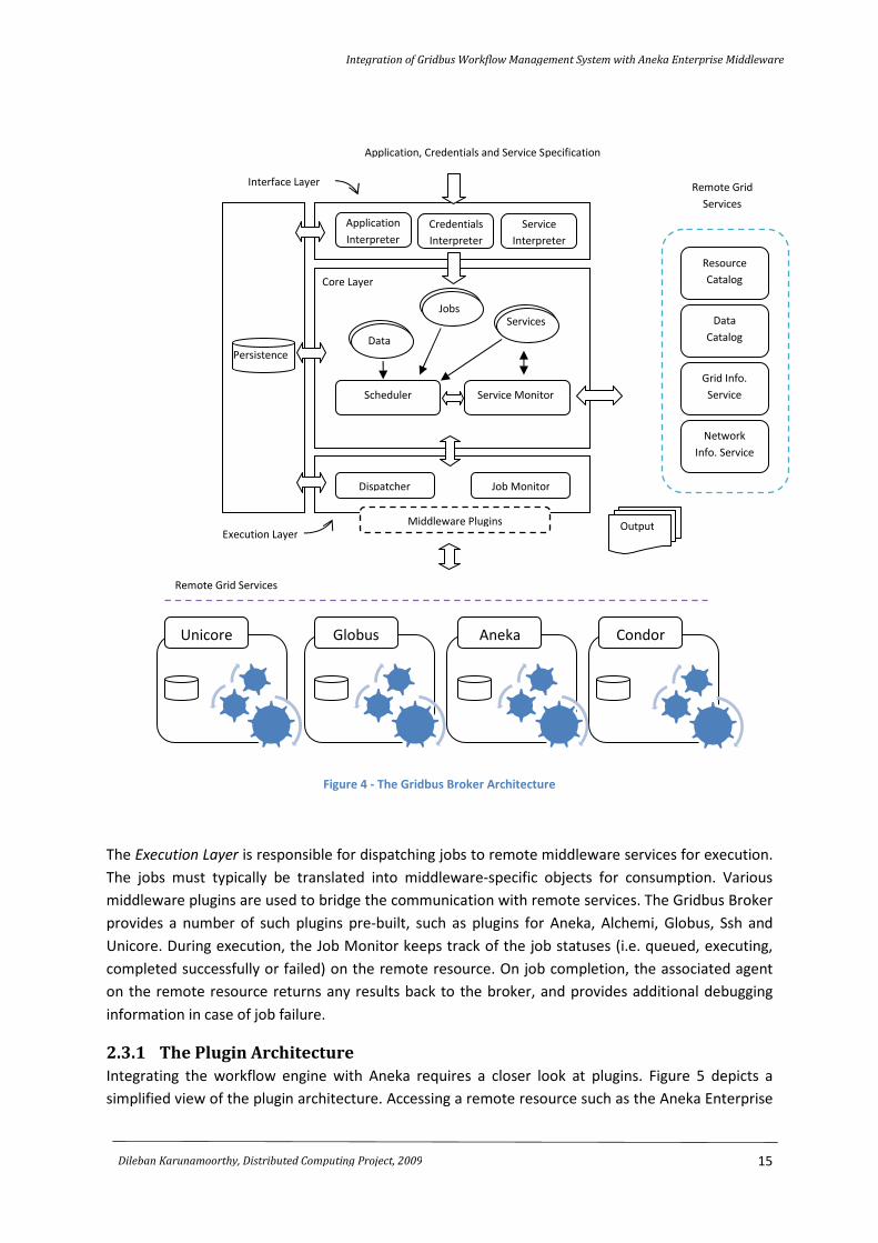
2.3.1 The Plugin Architecture
Integrating the workflow engine with Aneka requires a closer look at plugins. Figure 5 depicts a
simplified view of the plugin architecture. Accessing a remote resource such as the Aneka Enterprise
Resource
Catalog
Data
Catalog
Grid Info.
Service
Network
Info. Service
Persistence
Output
Scheduler Service Monitor
Dispatcher Job Monitor
Application
Interpreter
Credentials
Interpreter
Service
Interpreter
Data
Jobs Services
Remote Grid
Services
Unicore Globus Aneka Condor
Remote Grid Services
Application, Credentials and Service Specification
Middleware Plugins
Interface Layer
Core Layer
Execution Layer
Integration of Gridbus Workflow Management System with Aneka Enterprise Middleware
16
Dileban Karunamoorthy, Distributed Computing Project, 2009
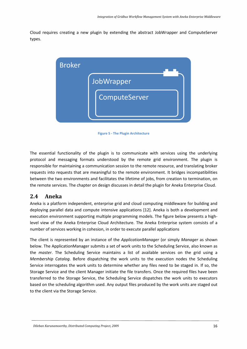
Cloud requires creating a new plugin by extending the abstract JobWrapper and ComputeServer
types.
Figure 5 - The Plugin Architecture
The essential functionality of the plugin is to communicate with services using the underlying
protocol and messaging formats understood by the remote grid environment. The plugin is
responsible for maintaining a communication session to the remote resource, and translating broker
requests into requests that are meaningful to the remote environment. It bridges incompatibilities
between the two environments and facilitates the lifetime of jobs, from creation to termination, on
the remote services. The chapter on design discusses in detail the plugin for Aneka Enterprise Cloud.
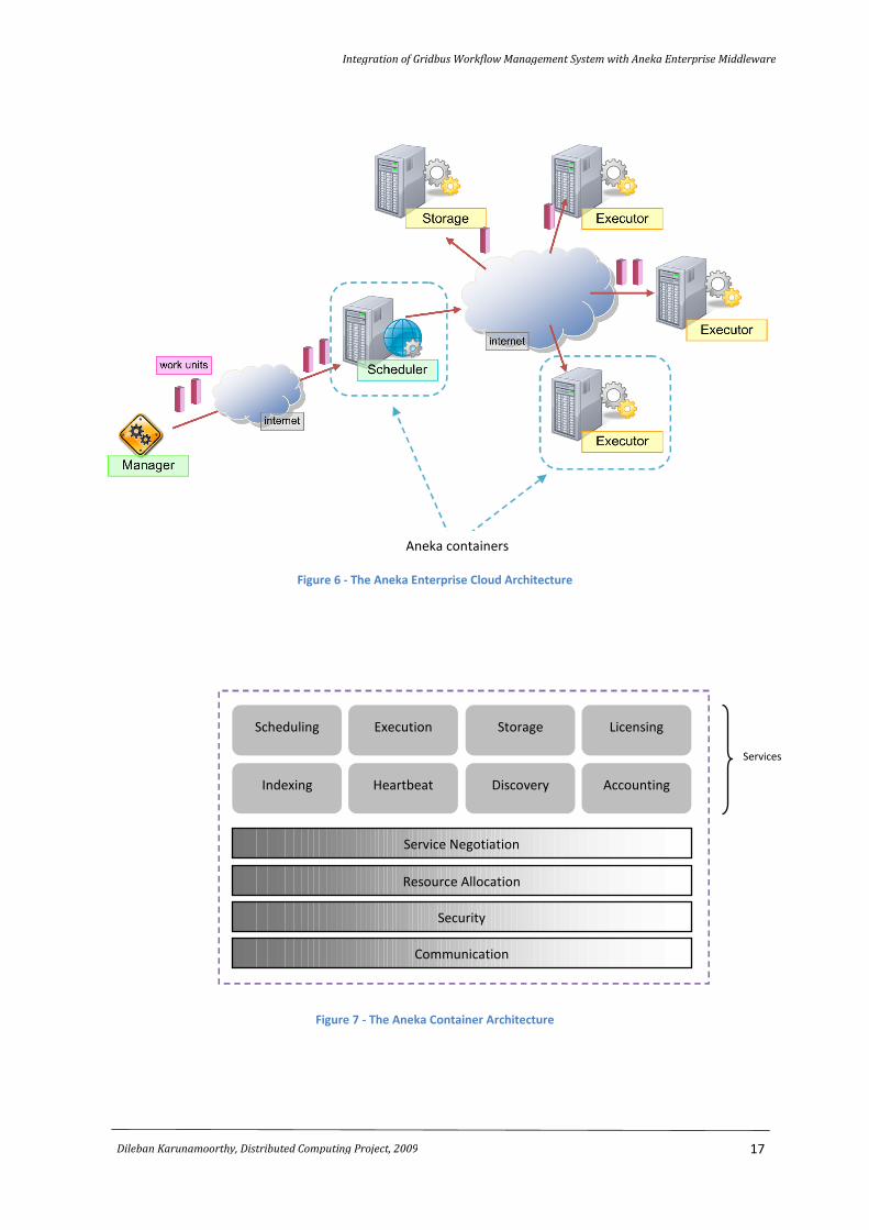
2.4 Aneka Aneka is a platform independent, enterprise grid and cloud computing middleware for building and
deploying parallel data and compute intensive applications [12]. Aneka is both a development and
execution environment supporting multiple programming models. The figure below presents a high-
level view of the Aneka Enterprise Cloud Architecture. The Aneka Enterprise system consists of a
number of services working in cohesion, in order to execute parallel applications
The client is represented by an instance of the ApplicationManager (or simply Manager as shown
below. The ApplicationManager submits a set of work units to the Scheduling Service, also known as
the master. The Scheduling Service maintains a list of available services on the grid using a
Membership Catalog. Before dispatching the work units to the execution nodes the Scheduling
Service interrogates the work units to determine whether any files need to be staged in. If so, the
Storage Service and the client Manager initiate the file transfers. Once the required files have been
transferred to the Storage Service, the Scheduling Service dispatches the work units to executors
based on the scheduling algorithm used. Any output files produced by the work units are staged out
to the client via the Storage Service.
Broker
JobWrapper
ComputeServer
Integration of Gridbus Workflow Management System with Aneka Enterprise Middleware
17
Dileban Karunamoorthy, Distributed Computing Project, 2009
Figure 6 - The Aneka Enterprise Cloud Architecture
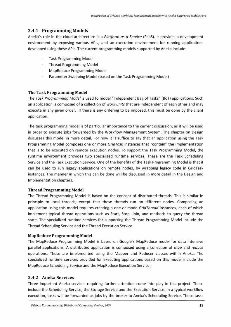
Figure 7 - The Aneka Container Architecture
Aneka containers
Communication
Security
Resource Allocation
Service Negotiation
Scheduling
Indexing
Execution
Heartbeat
Storage
Discovery
Licensing
Accounting
Services
Integration of Gridbus Workflow Management System with Aneka Enterprise Middleware
18
Dileban Karunamoorthy, Distributed Computing Project, 2009
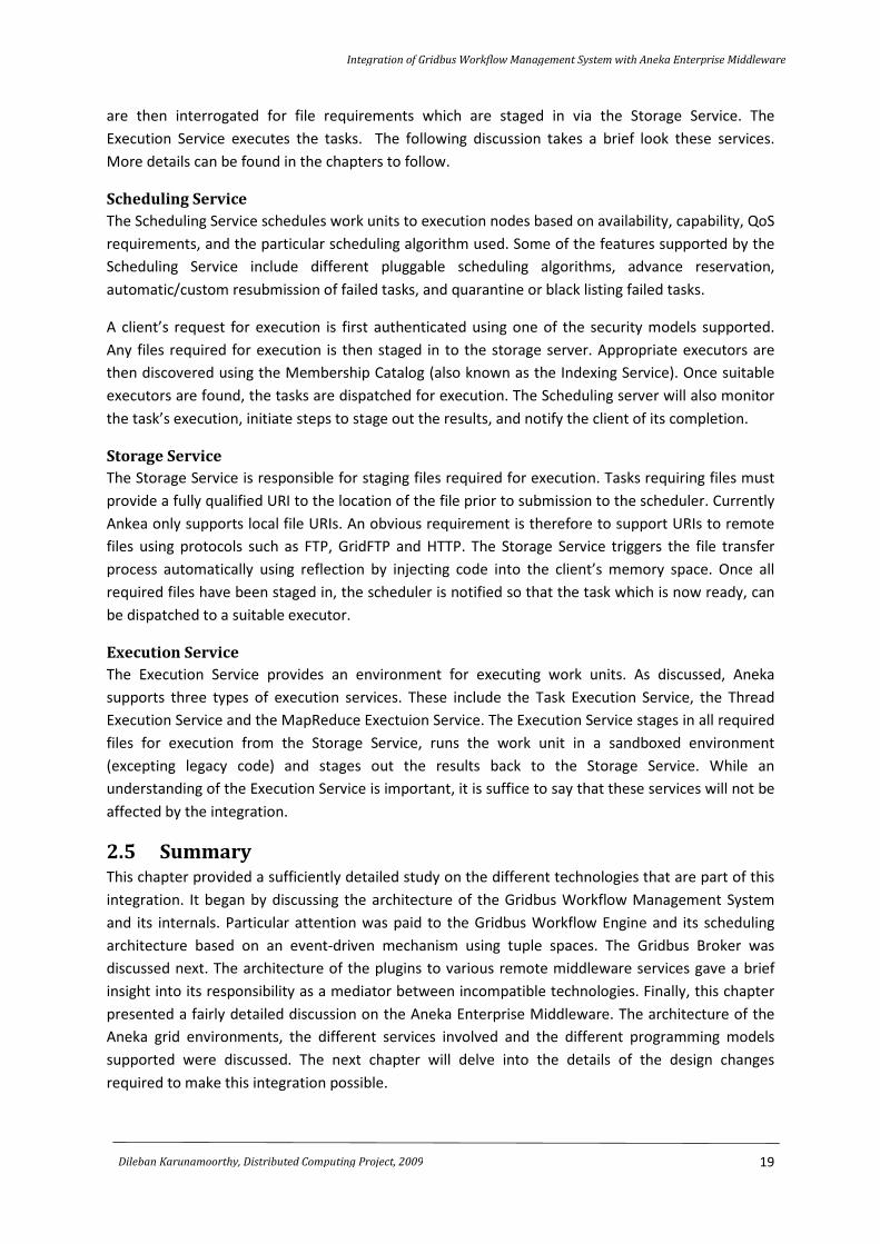
2.4.1 Programming Models
Aneka’s role in the cloud architecture is a Platform as a Service (PaaS). It provides a development
environment by exposing various APIs, and an execution environment for running applications
developed using these APIs. The current programming models supported by Aneka include:
- Task Programming Model
- Thread Programming Model
- MapReduce Programming Model
- Parameter Sweeping Model (based on the Task Programming Model)
The Task Programming Model
The Task Programming Model is used to model “Independent Bag of Tasks” (BoT) applications. Such
an application is composed of a collection of work units that are independent of each other and may
execute in any given order. If there is any ordering to be imposed, this must be done by the client
application.
The task programming model is of particular importance to the current discussion, as it will be used
in order to execute jobs forwarded by the Workflow Management System. The chapter on Design
discusses this model in more detail. For now it is suffice to say that an application using the Task
Programming Model composes one or more GridTask instances that “contain” the implementation
that is to be executed on remote execution nodes. To support the Task Programming Model, the
runtime environment provides two specialized runtime services. These are the Task Scheduling
Service and the Task Execution Service. One of the benefits of the Task Programming Model is that it
can be used to run legacy applications on remote nodes, by wrapping legacy code in GridTask
instances. The manner in which this can be done will be discussed in more detail in the Design and
Implementation chapters.
Thread Programming Model
The Thread Programming Model is based on the concept of distributed threads. This is similar in
principle to local threads, except that these threads run on different nodes. Composing an
application using this model requires creating a one or mode GridThread instances, each of which
implement typical thread operations such as Start, Stop, Join, and methods to query the thread
state. The specialized runtime services for supporting the Thread Programming Model include the
Thread Scheduling Service and the Thread Execution Service.
MapReduce Programming Model
The MapReduce Programming Model is based on Google’s MapReduce model for data intensive
parallel applications. A distributed application is composed using a collection of map and reduce
operations. These are implemented using the Mapper and Reducer classes within Aneka. The
specialized runtime services provided for executing applications based on this model include the
MapReduce Scheduling Service and the MapReduce Execution Service.
2.4.2 Aneka Services
Three important Aneka services requiring further attention come into play in this project. These
include the Scheduling Service, the Storage Service and the Execution Service. In a typical workflow
execution, tasks will be forwarded as jobs by the broker to Aneka’s Scheduling Service. These tasks
Integration of Gridbus Workflow Management System with Aneka Enterprise Middleware
19
Dileban Karunamoorthy, Distributed Computing Project, 2009
are then interrogated for file requirements which are staged in via the Storage Service. The
Execution Service executes the tasks. The following discussion takes a brief look these services.
More details can be found in the chapters to follow.
Scheduling Service
The Scheduling Service schedules work units to execution nodes based on availability, capability, QoS
requirements, and the particular scheduling algorithm used. Some of the features supported by the
Scheduling Service include different pluggable scheduling algorithms, advance reservation,
automatic/custom resubmission of failed tasks, and quarantine or black listing failed tasks.
A client’s request for execution is first authenticated using one of the security models supported.
Any files required for execution is then staged in to the storage server. Appropriate executors are
then discovered using the Membership Catalog (also known as the Indexing Service). Once suitable
executors are found, the tasks are dispatched for execution. The Scheduling server will also monitor
the task’s execution, initiate steps to stage out the results, and notify the client of its completion.
Storage Service
The Storage Service is responsible for staging files required for execution. Tasks requiring files must
provide a fully qualified URI to the location of the file prior to submission to the scheduler. Currently
Ankea only supports local file URIs. An obvious requirement is therefore to support URIs to remote
files using protocols such as FTP, GridFTP and HTTP. The Storage Service triggers the file transfer
process automatically using reflection by injecting code into the client’s memory space. Once all
required files have been staged in, the scheduler is notified so that the task which is now ready, can
be dispatched to a suitable executor.
Execution Service
The Execution Service provides an environment for executing work units. As discussed, Aneka
supports three types of execution services. These include the Task Execution Service, the Thread
Execution Service and the MapReduce Exectuion Service. The Execution Service stages in all required
files for execution from the Storage Service, runs the work unit in a sandboxed environment
(excepting legacy code) and stages out the results back to the Storage Service. While an
understanding of the Execution Service is important, it is suffice to say that these services will not be
affected by the integration.
2.5 Summary This chapter provided a sufficiently detailed study on the different technologies that are part of this
integration. It began by discussing the architecture of the Gridbus Workflow Management System
and its internals. Particular attention was paid to the Gridbus Workflow Engine and its scheduling
architecture based on an event-driven mechanism using tuple spaces. The Gridbus Broker was
discussed next. The architecture of the plugins to various remote middleware services gave a brief
insight into its responsibility as a mediator between incompatible technologies. Finally, this chapter
presented a fairly detailed discussion on the Aneka Enterprise Middleware. The architecture of the
Aneka grid environments, the different services involved and the different programming models
supported were discussed. The next chapter will delve into the details of the design changes
required to make this integration possible.
CHAPTER 3
Design
Chapter Contents:
3.1 Introduction
3.2 High-Level Architectural Design
3.3 Task Web Service
3.3.1 Web Services and Web Methods
Application Creation and Job Submission
Querying Application and Job Status
3.4 The Gridbus Broker and the Aneka Plugin
3.5 Mapping Job Statuses to Task Statuses
3.6 Design Changes to Aneka
3.6.1 Scheduling Service
3.6.2 Storage Service
3.7 Interaction Diagrams
3.7.1 Application Creation
3.7.2 Job Submission
3.8 Summary
Integration of Gridbus Workflow Management System with Aneka Enterprise Middleware
21
Dileban Karunamoorthy, Distributed Computing Project, 2009
3.1 Introduction A high-level design of the integration of the Gridbus Workflow Management System and Aneka
Enterprise Middleware will provide the necessary architectural understanding of the different
components involved and their interactions. This will naturally lead into the low-level component
and class design of the different modules involved. A detailed design is essential for two reasons.
First it makes it makes it easier to understand how the implementation should be carried out.
Second it will help in understanding how the design changes will affect the existing code, providing a
safety net.
This chapter begins by presenting a high-level architectural design of the integration. This is followed
by a detailed design of the Task Web Service. The Aneka plugin for the broker is discussed next. The
chapter then looks at the design changes to the different Aneka services. The chapter ends with a
series of sequence diagram showing how the overall integration is realized.
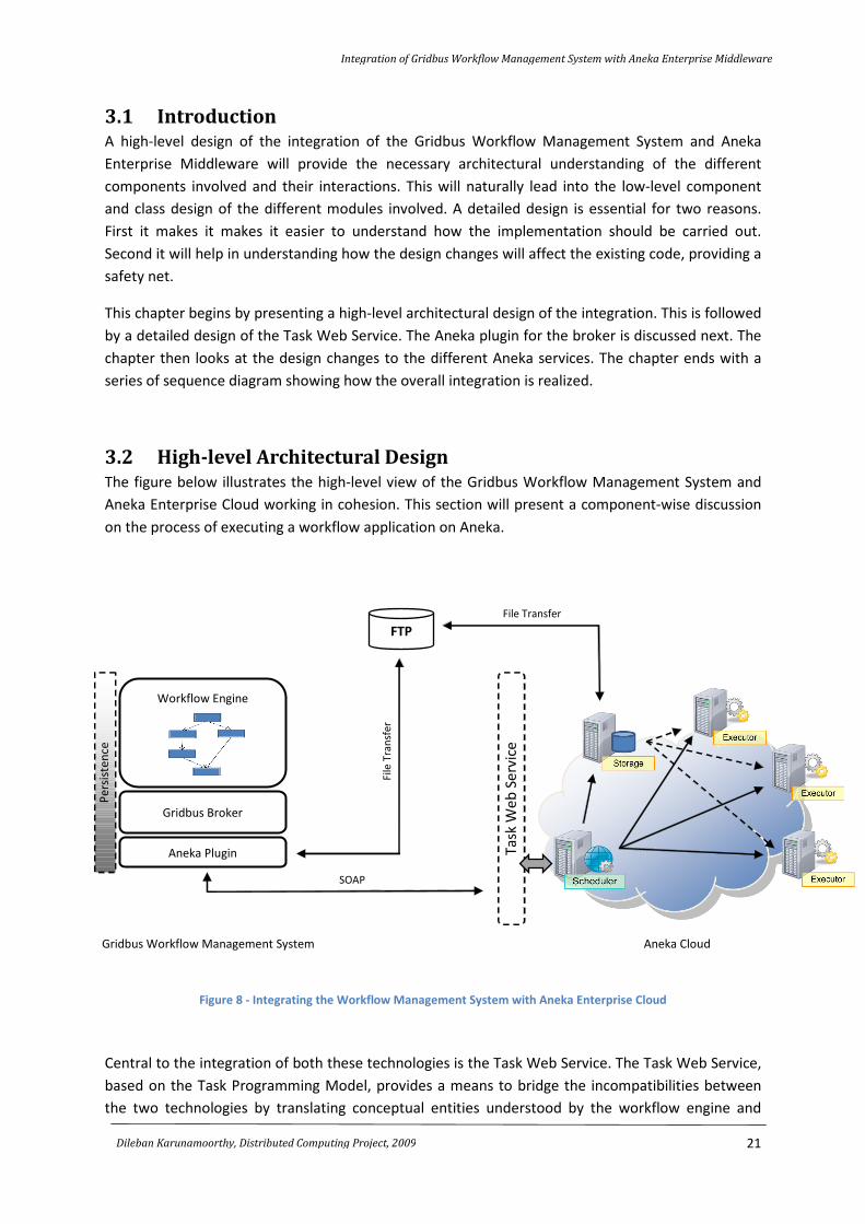
3.2 High-level Architectural Design The figure below illustrates the high-level view of the Gridbus Workflow Management System and
Aneka Enterprise Cloud working in cohesion. This section will present a component-wise discussion
on the process of executing a workflow application on Aneka.
Figure 8 - Integrating the Workflow Management System with Aneka Enterprise Cloud
Central to the integration of both these technologies is the Task Web Service. The Task Web Service,
based on the Task Programming Model, provides a means to bridge the incompatibilities between
the two technologies by translating conceptual entities understood by the workflow engine and
FTP
Ta
sk W
eb
Se
rvic
e
Workflow Engine
Gridbus Broker
Aneka Plugin
Pe
rsis
ten
ce
Aneka Cloud
File Transfer
File
Tra
nsf
er
SOAP
Gridbus Workflow Management System
Integration of Gridbus Workflow Management System with Aneka Enterprise Middleware
22
Dileban Karunamoorthy, Distributed Computing Project, 2009
broker into those understandable by Aneka. The stateless nature of Web Services requires that any
stateful information must be passed back-and-forth between the broker and Aneka.
The workflow engine translates tasks defined in the workflow language into a set of jobs
understandable by the broker. The service configuration specifies the need to use an instance of the
Ankea Enterprise Cloud for task execution. This would initiate the Gridbus Broker to create an
instance of the Aneka Plugin for creating and managing jobs on the remote resources. In Aneka, all
jobs must belong to an application. An application has a globally unique identifier (or GUID), and all
jobs (or tasks) associated with an application in Ankea are linked via this GUID. The first step for the
broker therefore is to create an Aneka application. This is done by way of instantiating the Aneka
Plugin. This results in a SOAP request to the Task Web Service, which creates and returns the GUID
of a new application. All jobs subsequently submitted to Aneka via the Web Service would now use
this GUID.
A job submission involves composing a SOAP message specifying the command to execute, its
parameters, the required input files, the list of output files produced and the application’s GUID. This
message is forwarded to the Task Web Service. The Task Web Service would now create Aneka
GridTask instances on behalf of the plugin based on a set of pre-defined base tasks. The new Aneka
tasks are subsequently submitted to the scheduler for execution and the corresponding task IDs
returned to the broker. The scheduler would then interrogate the work unit in order to determine
whether the task requires any remote files for execution. Note that this is a deviation from the
standard behavior in which the client would automatically begin staging in local files after submitting
the work unit. This behavioral change in the scheduler for dealing with remote files in particular
requires further discussion.
Remote files refer to those hosted on remote servers on the Internet. Local files in contrast are
hosted on the client’s local machine, which Aneka assumes to be running on the .Net runtime. This
enables Aneka to migrate .Net code to the client’s process space, initiating an automatic transfer of
files to the Storage Service. Support for remote files on the other hand would enable clients written
in any technology to interact with Aneka and stage-in files using standard Internet protocols such as
FTP and HTTP. The behavioral changes introduced to the Scheduling Service would now trigger the
Storage Service to pull in all files required by the work unit from remote locations. These files are
hosted locally and made available to the execution nodes. When a work unit is ready for execution,
it is dispatched to an execution node. All files are staged in to the execution service, the task is
executed, and the results staged out back to the Storage Service. The output files now have to be
staged back to the remote server for collecting by the client.
The Scheduling Service coordinates the entire process controlling the state of the work unit as it
goes through the different stages of execution. In order to allow remote clients, including the
broker, to monitor the application and work units, the Task Web Service provides web methods to
query their statuses. An issue that needs to be dealt with when exchanging status information is that
they should make sense within different contexts, i.e. within Aneka and within the broker. Although
in general, it is possible to make a one-to-one mapping between the statuses in the two different
contexts, this is not always the case.
Integration of Gridbus Workflow Management System with Aneka Enterprise Middleware
23
Dileban Karunamoorthy, Distributed Computing Project, 2009
3.3 Task Web Service The Task Web Service exposes Aneka as a service to non-.Net applications. Based on the Task
Programming Model, the Task Web Service allows clients to submit generic jobs to Aneka for
execution. Note that the Task Web Service will be an extension to an older existing implementation
based on .Net, and as such the following discussion on its design will be based on designing Web
Services using Microsoft’s ASP.Net. The following are the design specifications for the Task Web
Service.
3.3.1 Web Services and Web Methods
Web Services enable heterogenous systems to communicate with each other using a common
language. While Web Services provide a loose coupleing of different systems, older technolgoies
such as DCOM, CORBA (IIOP) and Java RMI enforce tight coupling and as a result dictate the
technologies used to integrate them. Web Services however require that the communicating
systems understand the messages exchanged. These messages are defined via a contract using
WSDL and XSD. The XML-based protocol (such as SOAP) used to communicate with one another also
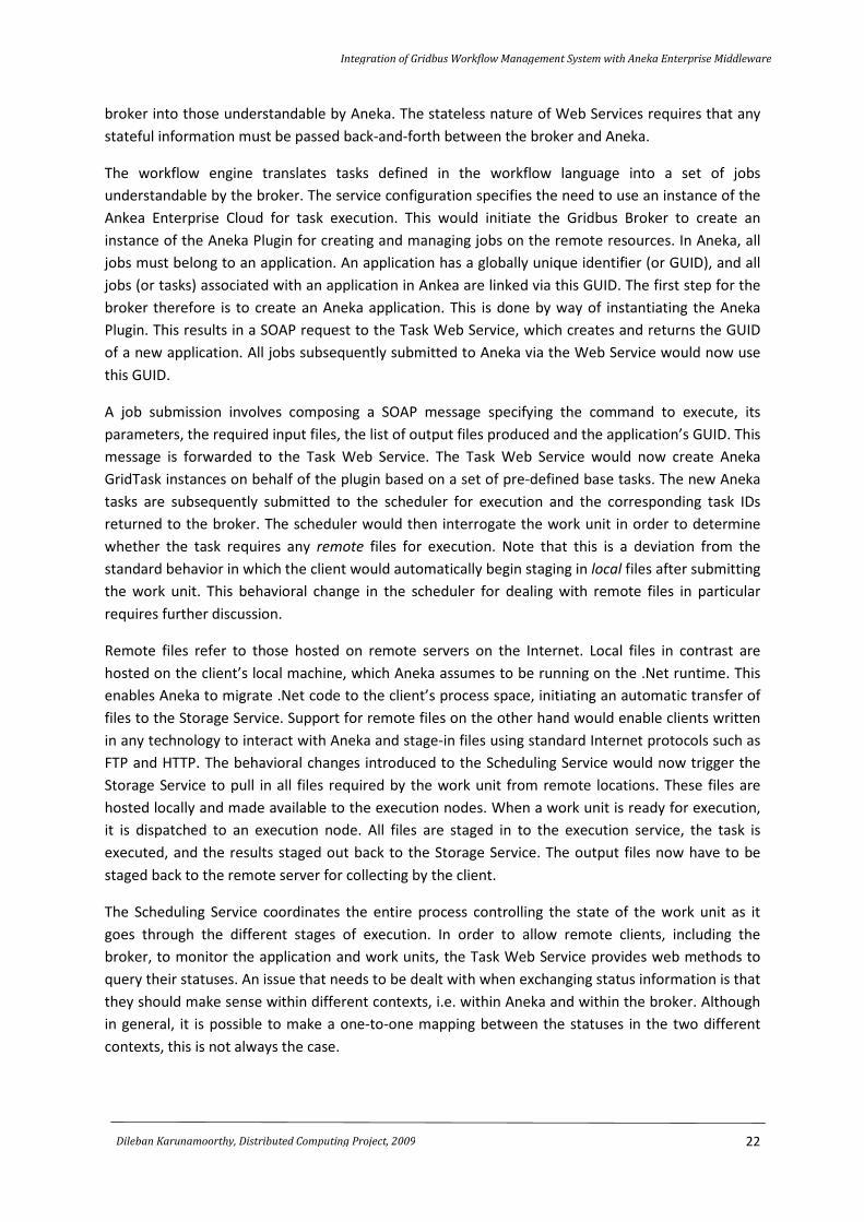
provides additional flexibility through easy extensibility. Error! Reference source not found. below
shows the Web Methods exposed by the Task Web Service.
Methods exposed by the Task
Web Service.
Figure 9 - The class diagram for the TaskService, the core component of the Task Web Service
Optional base class for XML Web
services, which provides direct access
to common ASP.NET objects, such as
application and session state.
Integration of Gridbus Workflow Management System with Aneka Enterprise Middleware
24
Dileban Karunamoorthy, Distributed Computing Project, 2009
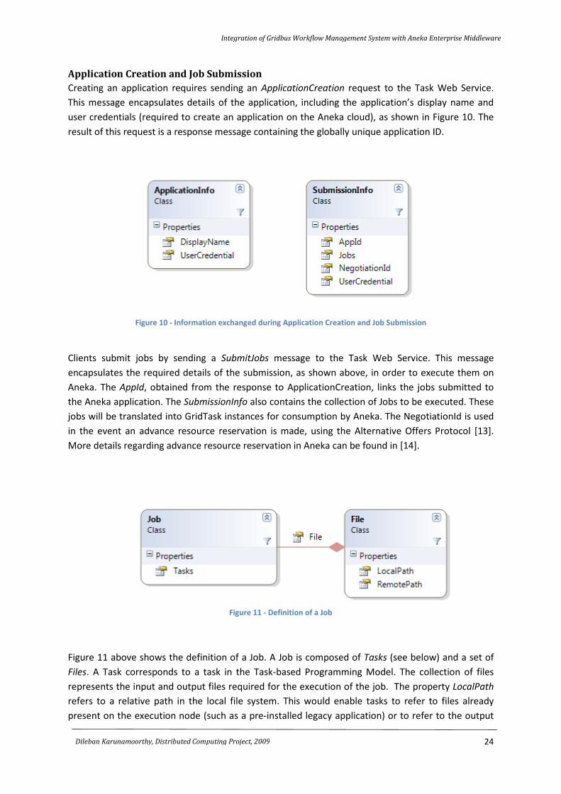
Application Creation and Job Submission
Creating an application requires sending an ApplicationCreation request to the Task Web Service.
This message encapsulates details of the application, including the application’s display name and
user credentials (required to create an application on the Aneka cloud), as shown in Figure 10. The
result of this request is a response message containing the globally unique application ID.
Figure 10 - Information exchanged during Application Creation and Job Submission
Clients submit jobs by sending a SubmitJobs message to the Task Web Service. This message
encapsulates the required details of the submission, as shown above, in order to execute them on
Aneka. The AppId, obtained from the response to ApplicationCreation, links the jobs submitted to
the Aneka application. The SubmissionInfo also contains the collection of Jobs to be executed. These
jobs will be translated into GridTask instances for consumption by Aneka. The NegotiationId is used
in the event an advance resource reservation is made, using the Alternative Offers Protocol [13].
More details regarding advance resource reservation in Aneka can be found in [14].
Figure 11 - Definition of a Job
Figure 11 above shows the definition of a Job. A Job is composed of Tasks (see below) and a set of
Files. A Task corresponds to a task in the Task-based Programming Model. The collection of files
represents the input and output files required for the execution of the job. The property LocalPath
refers to a relative path in the local file system. This would enable tasks to refer to files already
present on the execution node (such as a pre-installed legacy application) or to refer to the output
Integration of Gridbus Workflow Management System with Aneka Enterprise Middleware
25
Dileban Karunamoorthy, Distributed Computing Project, 2009
files created on the disk during the execution of a task. The property RemotePath refers to the fully
qualified Internet URI of a remote file to be staged in or staged out.
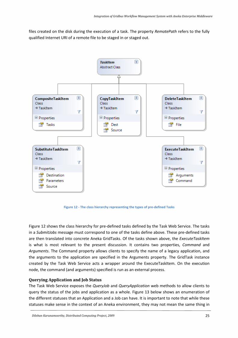
Figure 12 - The class hierarchy representing the types of pre-defined Tasks
Figure 12 shows the class hierarchy for pre-defined tasks defined by the Task Web Service. The tasks
in a SubmitJobs message must correspond to one of the tasks define above. These pre-defined tasks
are then translated into concrete Aneka GridTasks. Of the tasks shown above, the ExecuteTaskItem
is what is most relevant to the present discussion. It contains two properties, Command and
Arguments. The Command property allows clients to specify the name of a legacy application, and
the arguments to the application are specified in the Arguments property. The GridTask instance
created by the Task Web Service acts a wrapper around the ExecuteTaskItem. On the execution
node, the command (and arguments) specified is run as an external process.
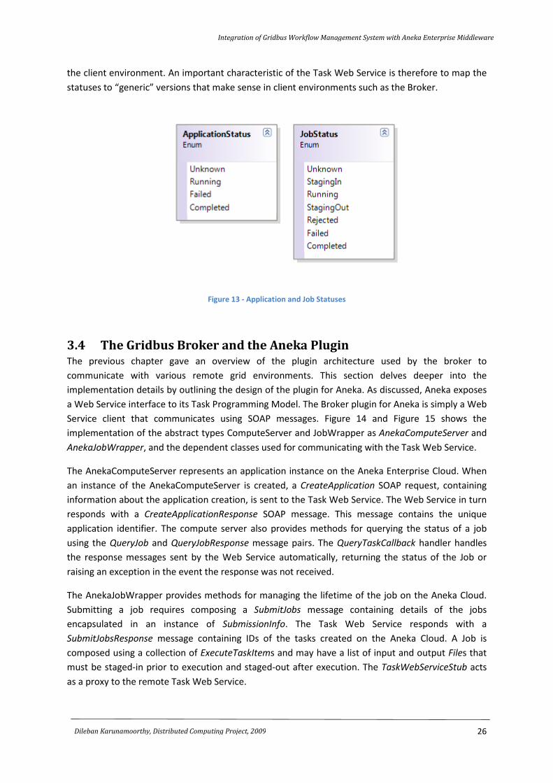
Querying Application and Job Status
The Task Web Service exposes the QueryJob and QueryApplication web methods to allow clients to
query the status of the jobs and application as a whole. Figure 13 below shows an enumeration of
the different statuses that an Application and a Job can have. It is important to note that while these
statuses make sense in the context of an Aneka environment, they may not mean the same thing in
Integration of Gridbus Workflow Management System with Aneka Enterprise Middleware
26
Dileban Karunamoorthy, Distributed Computing Project, 2009
the client environment. An important characteristic of the Task Web Service is therefore to map the
statuses to “generic” versions that make sense in client environments such as the Broker.
Figure 13 - Application and Job Statuses
3.4 The Gridbus Broker and the Aneka Plugin The previous chapter gave an overview of the plugin architecture used by the broker to
communicate with various remote grid environments. This section delves deeper into the
implementation details by outlining the design of the plugin for Aneka. As discussed, Aneka exposes
a Web Service interface to its Task Programming Model. The Broker plugin for Aneka is simply a Web
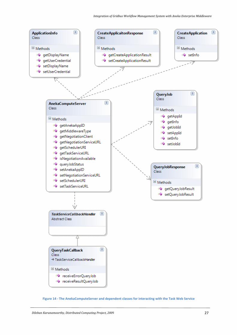
Service client that communicates using SOAP messages. Figure 14 and Figure 15 shows the
implementation of the abstract types ComputeServer and JobWrapper as AnekaComputeServer and
AnekaJobWrapper, and the dependent classes used for communicating with the Task Web Service.
The AnekaComputeServer represents an application instance on the Aneka Enterprise Cloud. When
an instance of the AnekaComputeServer is created, a CreateApplication SOAP request, containing
information about the application creation, is sent to the Task Web Service. The Web Service in turn
responds with a CreateApplicationResponse SOAP message. This message contains the unique
application identifier. The compute server also provides methods for querying the status of a job
using the QueryJob and QueryJobResponse message pairs. The QueryTaskCallback handler handles
the response messages sent by the Web Service automatically, returning the status of the Job or
raising an exception in the event the response was not received.
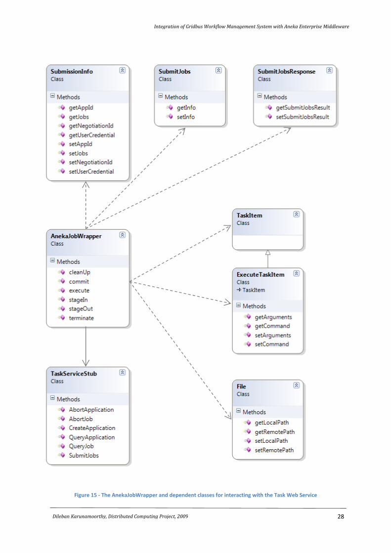
The AnekaJobWrapper provides methods for managing the lifetime of the job on the Aneka Cloud.
Submitting a job requires composing a SubmitJobs message containing details of the jobs
encapsulated in an instance of SubmissionInfo. The Task Web Service responds with a
SubmitJobsResponse message containing IDs of the tasks created on the Aneka Cloud. A Job is
composed using a collection of ExecuteTaskItems and may have a list of input and output Files that
must be staged-in prior to execution and staged-out after execution. The TaskWebServiceStub acts
as a proxy to the remote Task Web Service.
Integration of Gridbus Workflow Management System with Aneka Enterprise Middleware
27
Dileban Karunamoorthy, Distributed Computing Project, 2009
Figure 14 - The AnekaComputeServer and dependent classes for interacting with the Task Web Service
Integration of Gridbus Workflow Management System with Aneka Enterprise Middleware
28
Dileban Karunamoorthy, Distributed Computing Project, 2009
Figure 15 - The AnekaJobWrapper and dependent classes for interacting with the Task Web Service
Integration of Gridbus Workflow Management System with Aneka Enterprise Middleware
29
Dileban Karunamoorthy, Distributed Computing Project, 2009
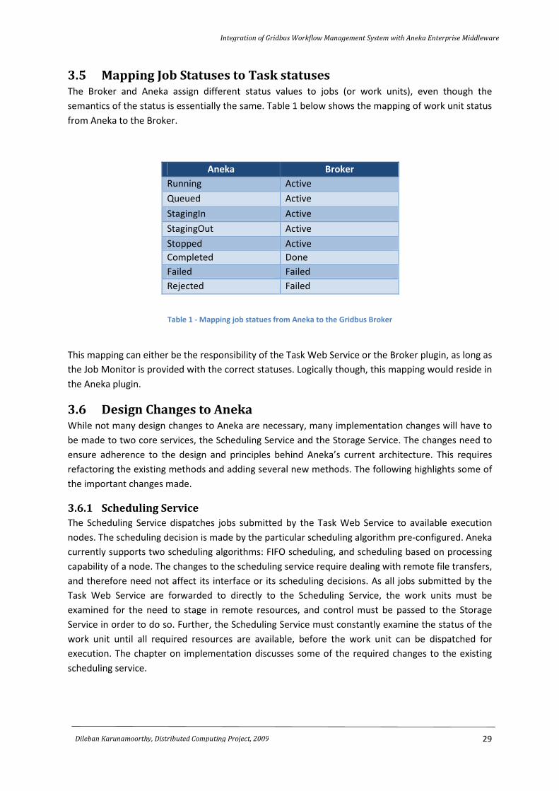
3.5 Mapping Job Statuses to Task statuses The Broker and Aneka assign different status values to jobs (or work units), even though the
semantics of the status is essentially the same. Table 1 below shows the mapping of work unit status
from Aneka to the Broker.
Aneka Broker
Running Active
Queued Active
StagingIn Active
StagingOut Active
Stopped Active
Completed Done
Failed Failed
Rejected Failed
Table 1 - Mapping job statues from Aneka to the Gridbus Broker
This mapping can either be the responsibility of the Task Web Service or the Broker plugin, as long as
the Job Monitor is provided with the correct statuses. Logically though, this mapping would reside in
the Aneka plugin.
3.6 Design Changes to Aneka While not many design changes to Aneka are necessary, many implementation changes will have to
be made to two core services, the Scheduling Service and the Storage Service. The changes need to
ensure adherence to the design and principles behind Aneka’s current architecture. This requires
refactoring the existing methods and adding several new methods. The following highlights some of
the important changes made.
3.6.1 Scheduling Service
The Scheduling Service dispatches jobs submitted by the Task Web Service to available execution
nodes. The scheduling decision is made by the particular scheduling algorithm pre-configured. Aneka
currently supports two scheduling algorithms: FIFO scheduling, and scheduling based on processing
capability of a node. The changes to the scheduling service require dealing with remote file transfers,
and therefore need not affect its interface or its scheduling decisions. As all jobs submitted by the
Task Web Service are forwarded to directly to the Scheduling Service, the work units must be
examined for the need to stage in remote resources, and control must be passed to the Storage
Service in order to do so. Further, the Scheduling Service must constantly examine the status of the
work unit until all required resources are available, before the work unit can be dispatched for
execution. The chapter on implementation discusses some of the required changes to the existing
scheduling service.
Integration of Gridbus Workflow Management System with Aneka Enterprise Middleware
30
Dileban Karunamoorthy, Distributed Computing Project, 2009
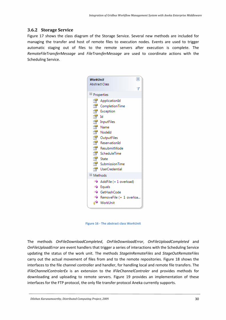
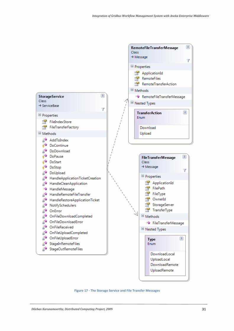
3.6.2 Storage Service
Figure 17 shows the class diagram of the Storage Service. Several new methods are included for
managing the transfer and host of remote files to execution nodes. Events are used to trigger
automatic staging out of files to the remote servers after execution is complete. The
RemoteFileTransferMessage and FileTransferMessage are used to coordinate actions with the
Scheduling Service.
Figure 16 - The abstract class WorkUnit
The methods OnFileDownloadCompleted, OnFileDownloadError, OnFileUploadCompleted and
OnFileUploadError are event handlers that trigger a series of interactions with the Scheduling Service
updating the status of the work unit. The methods StageInRemoteFiles and StageOutRemoteFiles
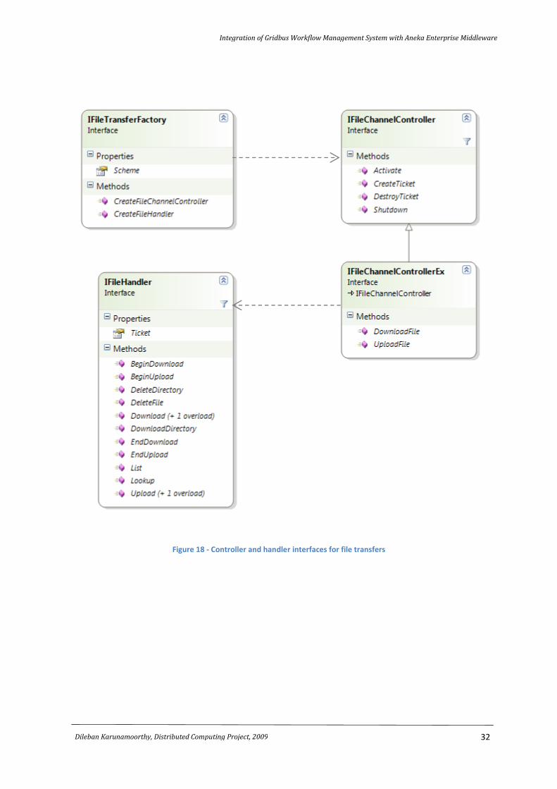
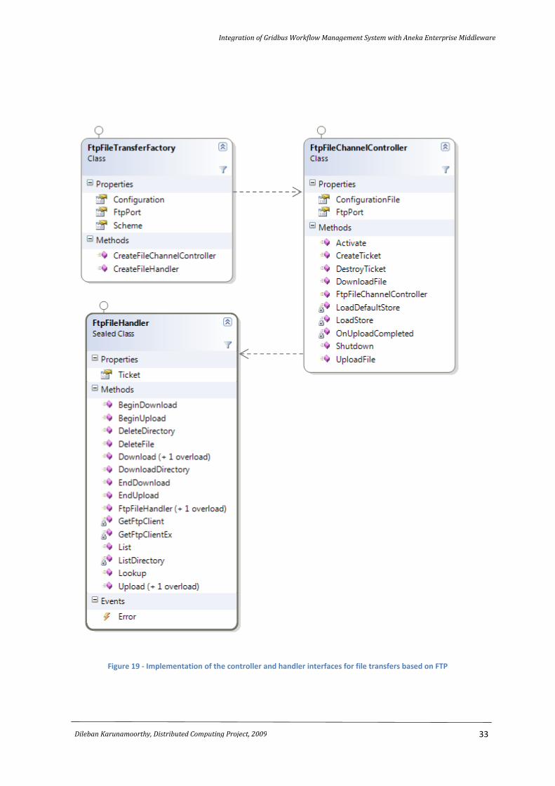
carry out the actual movement of files from and to the remote repositories. Figure 18 shows the
interfaces to the file channel controller and handler, for handling local and remote file transfers. The
IFileChannelControlerEx is an extension to the IFileChannelControler and provides methods for
downloading and uploading to remote servers. Figure 19 provides an implementation of these
interfaces for the FTP protocol, the only file transfer protocol Aneka currently supports.
Integration of Gridbus Workflow Management System with Aneka Enterprise Middleware
31
Dileban Karunamoorthy, Distributed Computing Project, 2009
Figure 17 - The Storage Service and File Transfer Messages
Integration of Gridbus Workflow Management System with Aneka Enterprise Middleware
32
Dileban Karunamoorthy, Distributed Computing Project, 2009
Figure 18 - Controller and handler interfaces for file transfers
Integration of Gridbus Workflow Management System with Aneka Enterprise Middleware
33
Dileban Karunamoorthy, Distributed Computing Project, 2009
Figure 19 - Implementation of the controller and handler interfaces for file transfers based on FTP
Integration of Gridbus Workflow Management System with Aneka Enterprise Middleware
34
Dileban Karunamoorthy, Distributed Computing Project, 2009
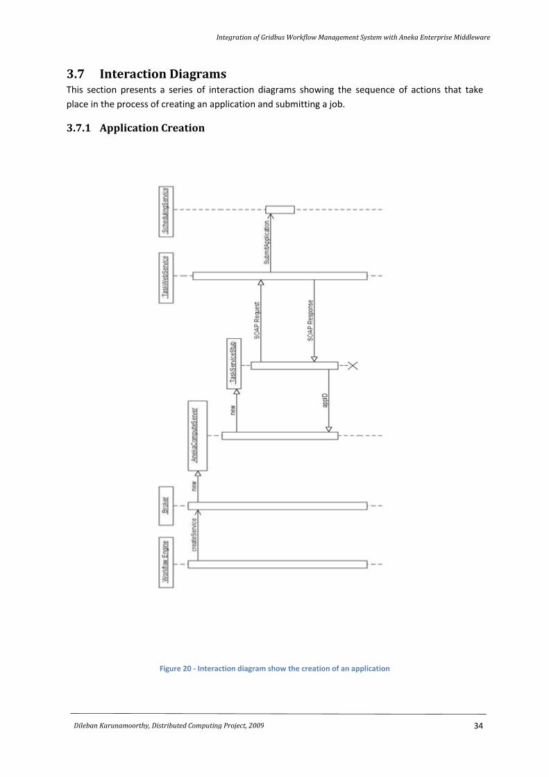
3.7 Interaction Diagrams This section presents a series of interaction diagrams showing the sequence of actions that take
place in the process of creating an application and submitting a job.
3.7.1 Application Creation
Figure 20 - Interaction diagram show the creation of an application
Integration of Gridbus Workflow Management System with Aneka Enterprise Middleware
35
Dileban Karunamoorthy, Distributed Computing Project, 2009
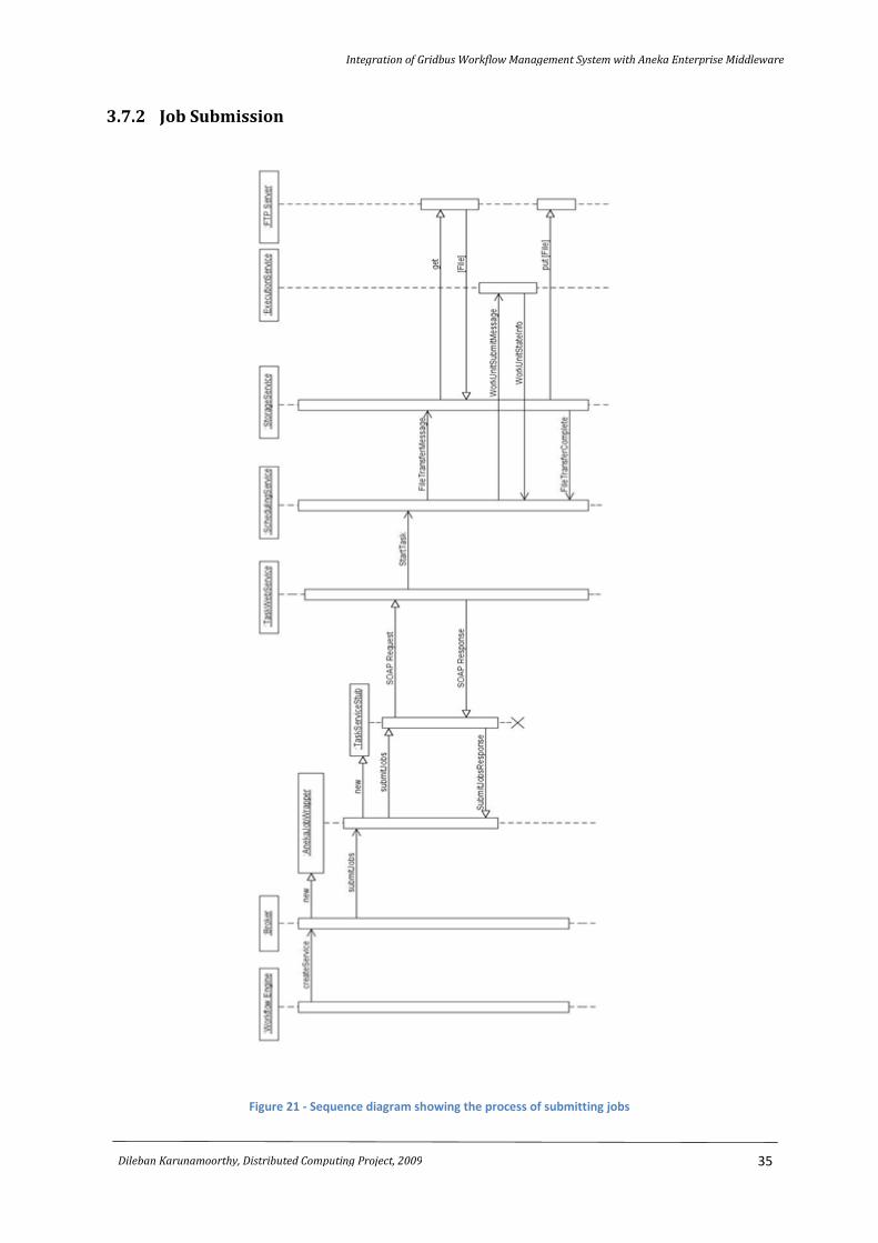
3.7.2 Job Submission
Figure 21 - Sequence diagram showing the process of submitting jobs

Integration of Gridbus Workflow Management System with Aneka Enterprise Middleware
36
Dileban Karunamoorthy, Distributed Computing Project, 2009
3.8 Summary This chapter began by presenting a high-level architecture of the integration of the Gridbus
Workflow Management System and Aneka Enterprise Middleware. The high-level architecture
provided an overall understanding of the process of creating and submitting jobs from the workflow
engine to Aneka. This was followed by a detailed discussion on the design of the Task Web Service.
The Web Service interface was illustrated. The chapter then detailed the design of the Aneka plugin
for the Gridbus Broker. The two main classes, AnekaComputeServer and AnekaJobWrapper, along
with their dependencies were shown. Finally, the chapter discussed the design changes to Aneka, in
particular to the Scheduling and Storage services. The chapter ended by showing two sequence
diagrams to illustrate the sequence of actions involved in the processing creating an application and
submitting jobs. The next chapter discusses some of the implementation details.
CHAPTER 4
Implementation
Chapter Contents:
4.1 Introduction
4.2 Task Web Service
4.2.1 Alternative Approaches
A Stateful Approach
A Stateless Approach Using “Bindapplication”
A Stateless Approach Using Taskmanagerhelper
4.3 Scheduling and Storage Services
4.4 Aneka Plugin for Gridbus Broker
4.4.1 Apache Xmlbeans Vs Apache Axis 2
4.5 Issues and Bugs Discovered
4.6 Summary
Integration of Gridbus Workflow Management System with Aneka Enterprise Middleware
38
Dileban Karunamoorthy, Distributed Computing Project, 2009
4.1 Introduction Although this chapter follows the chapter on design, in practice, implementation was carried out
iteratively with design and testing. The implementation changes to the Task Web Service, the Aneka
plugin and the Scheduling and Storage services were carried out in stages, and the process was
supported through the use of various tools. Many new issues relating to thread synchronization and
logical errors were discovered in both the workflow engine and Aneka, as a result of testing new
code paths that went untested.
This chapter begins by presenting the implementation of the Task Web Service and the alternative
design approaches considered. This is followed by the implementation changes made to the
Scheduling and Storage services. The implementation of the Aneka plugin is presented next. The
chapter ends with a discussion on some of the critical issues found.
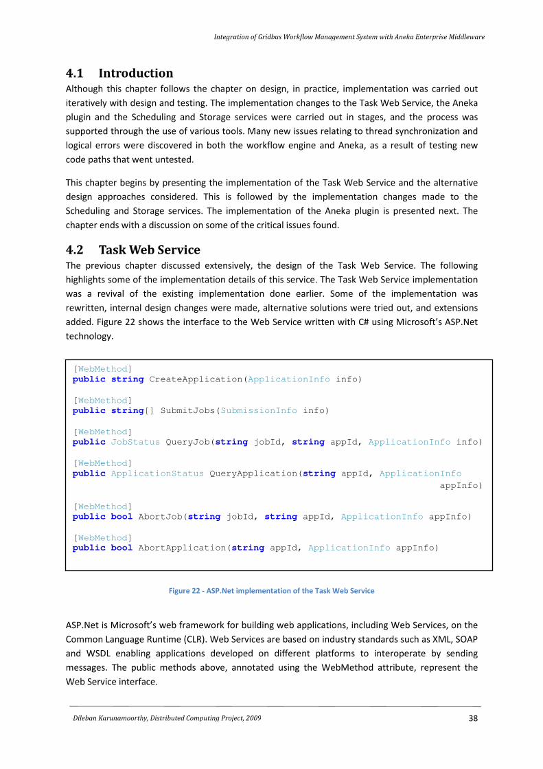
4.2 Task Web Service The previous chapter discussed extensively, the design of the Task Web Service. The following
highlights some of the implementation details of this service. The Task Web Service implementation
was a revival of the existing implementation done earlier. Some of the implementation was
rewritten, internal design changes were made, alternative solutions were tried out, and extensions
added. Figure 22 shows the interface to the Web Service written with C# using Microsoft’s ASP.Net
technology.
Figure 22 - ASP.Net implementation of the Task Web Service
ASP.Net is Microsoft’s web framework for building web applications, including Web Services, on the
Common Language Runtime (CLR). Web Services are based on industry standards such as XML, SOAP
and WSDL enabling applications developed on different platforms to interoperate by sending
messages. The public methods above, annotated using the WebMethod attribute, represent the
Web Service interface.
[WebMethod]
public string CreateApplication(ApplicationInfo info)
[WebMethod]
public string[] SubmitJobs(SubmissionInfo info)
[WebMethod]
public JobStatus QueryJob(string jobId, string appId, ApplicationInfo info)
[WebMethod]
public ApplicationStatus QueryApplication(string appId, ApplicationInfo
appInfo)
[WebMethod]
public bool AbortJob(string jobId, string appId, ApplicationInfo appInfo)
[WebMethod]
public bool AbortApplication(string appId, ApplicationInfo appInfo)
Integration of Gridbus Workflow Management System with Aneka Enterprise Middleware
39
Dileban Karunamoorthy, Distributed Computing Project, 2009
4.2.1 Alternative Approaches
While implementing the Task Web Service a number of alternative approaches were tried out
initially. Some of these approaches had drawbacks but nevertheless, it was interesting to experiment
and test the viability of the approach. The following lists two of the approaches that were
implemented and later discarded in preference to the third.
A Stateful Approach
A stateful approach by caching an instance of GridApplication (a client side representation of a grid
application on Aneka) was an initial design that was tried out. In this approach, the first time a
CreateApplication request was received a new GridApplication was created and cached in a global
data structure in the Web Service. A subsequent request received for submitting jobs would initiate
the Web Service to lookup the corresponding GridApplication instance based on the application
identifier. The actual submission to the Aneka network would then be made via the GridApplication
instance. The same would apply to query and abort requests. The obvious problem with using a
stateful approach is dealing with failures. In the even the Web Service crashes, the client loses
control over the application running on Aneka. Save the state to permanent storage would rectify
this problem, but would require a major overhaul in the design and changes to the core Aneka
middleware as well.
A Stateless Approach using “BindApplication”
The second alternative that was tried out, was to use a stateless approach in which the Web Service
would bind to an existing GridApplication instance by invoking its BindApplication() method. Initially,
on a CreateApplication request, a new GridApplication instance would be created and the
application started. Subsequent requests to submit, query or abort jobs were invoked on the
GridApplication’s BindApplication method. Once bound, the Web Service would have a concrete
GridApplication instance to work with. The downside of this approach was that the initial goal of the
BindApplication method was to deal with failing clients, enabling clients to re-bind on recovery.
Using the “side effects” of this approach for the Web Service brought many issues that conflicted in
principle. The other drawback of using this approach is that all remote files to be staged in must be
made available to the Web Service locally. This required either hosting a Web application on the
same host as the Web Service for managing file transfers, or transferring files over SOAP directly to
the Web Service. Both these methods were not viable.
A Stateless Approach using TaskManagerHelper
The solution implemented makes use of a utility class called the TaskManagerHelper. This class
provides a set of utility methods for interacting with the Aneka Enterprise Cloud without the use of a
GridApplication instance. By simply forwarding job creation, query and abortion requests directly to
the scheduler, this approach simplified the overall architecture, and also made it easy to transfer
files from remote locations without any dependence on a local Web application or the SOAP request
itself. This approach was ultimately implemented.
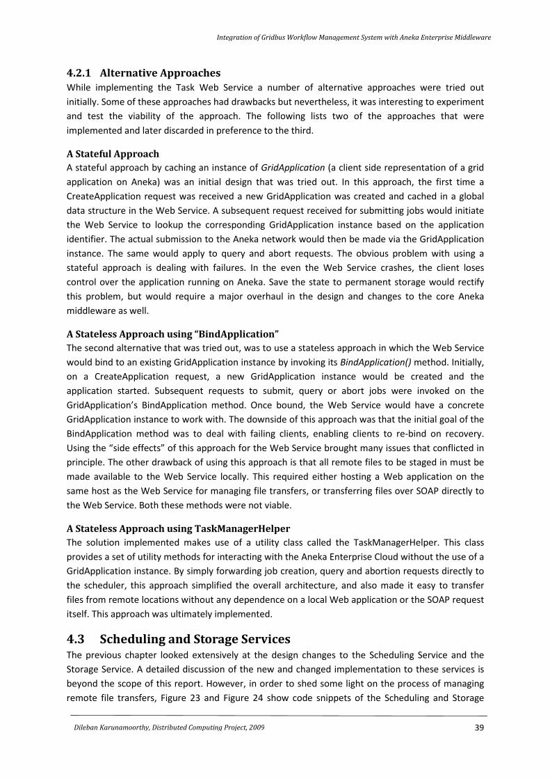
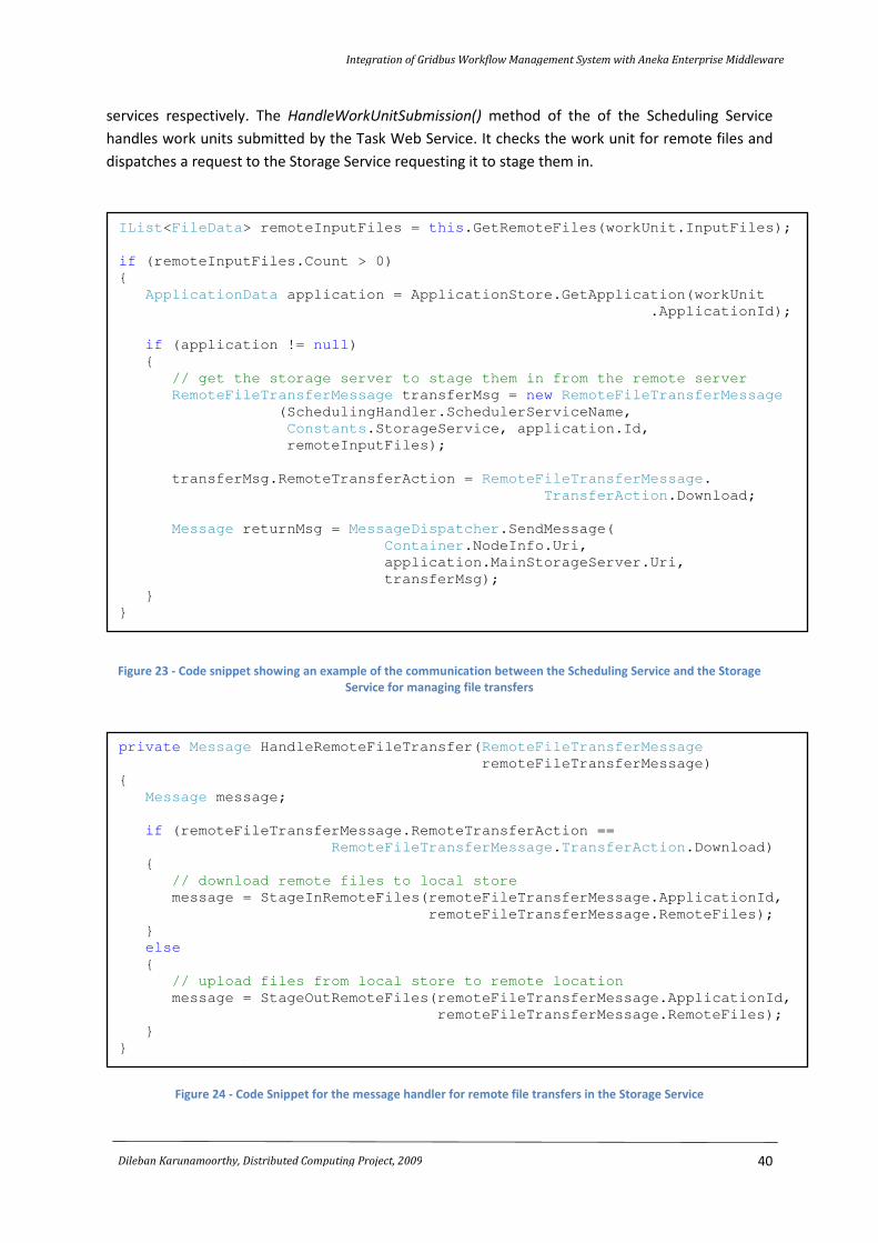
4.3 Scheduling and Storage Services The previous chapter looked extensively at the design changes to the Scheduling Service and the
Storage Service. A detailed discussion of the new and changed implementation to these services is
beyond the scope of this report. However, in order to shed some light on the process of managing
remote file transfers, Figure 23 and Figure 24 show code snippets of the Scheduling and Storage
Integration of Gridbus Workflow Management System with Aneka Enterprise Middleware
40
Dileban Karunamoorthy, Distributed Computing Project, 2009
services respectively. The HandleWorkUnitSubmission() method of the of the Scheduling Service
handles work units submitted by the Task Web Service. It checks the work unit for remote files and
dispatches a request to the Storage Service requesting it to stage them in.
Figure 23 - Code snippet showing an example of the communication between the Scheduling Service and the Storage
Service for managing file transfers
Figure 24 - Code Snippet for the message handler for remote file transfers in the Storage Service
IList<FileData> remoteInputFiles = this.GetRemoteFiles(workUnit.InputFiles);
if (remoteInputFiles.Count > 0)
{
ApplicationData application = ApplicationStore.GetApplication(workUnit
.ApplicationId);
if (application != null)
{
// get the storage server to stage them in from the remote server
RemoteFileTransferMessage transferMsg = new RemoteFileTransferMessage
(SchedulingHandler.SchedulerServiceName,
Constants.StorageService, application.Id,
remoteInputFiles);
transferMsg.RemoteTransferAction = RemoteFileTransferMessage.
TransferAction.Download;
Message returnMsg = MessageDispatcher.SendMessage(
Container.NodeInfo.Uri,
application.MainStorageServer.Uri,
transferMsg);
}
}
private Message HandleRemoteFileTransfer(RemoteFileTransferMessage
remoteFileTransferMessage)
{
Message message;
if (remoteFileTransferMessage.RemoteTransferAction ==
RemoteFileTransferMessage.TransferAction.Download)
{
// download remote files to local store
message = StageInRemoteFiles(remoteFileTransferMessage.ApplicationId,
remoteFileTransferMessage.RemoteFiles);
}
else
{
// upload files from local store to remote location
message = StageOutRemoteFiles(remoteFileTransferMessage.ApplicationId,
remoteFileTransferMessage.RemoteFiles);
}
}
return message;
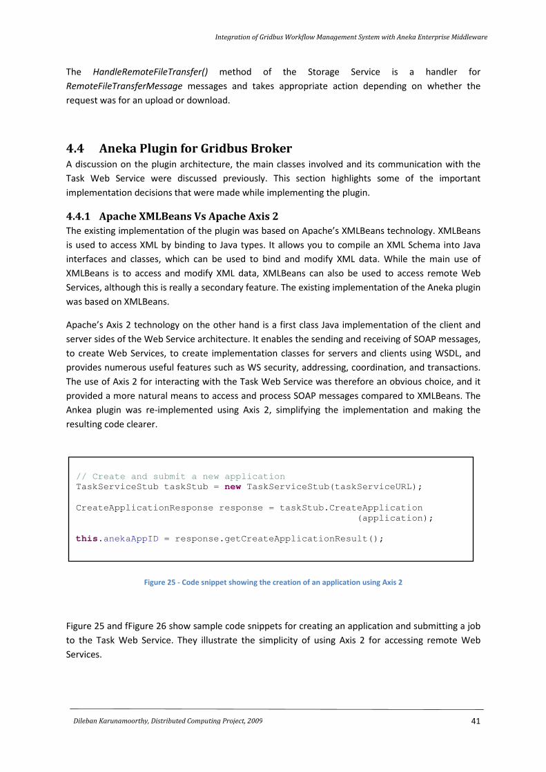
Integration of Gridbus Workflow Management System with Aneka Enterprise Middleware
41
Dileban Karunamoorthy, Distributed Computing Project, 2009
The HandleRemoteFileTransfer() method of the Storage Service is a handler for
RemoteFileTransferMessage messages and takes appropriate action depending on whether the
request was for an upload or download.
4.4 Aneka Plugin for Gridbus Broker A discussion on the plugin architecture, the main classes involved and its communication with the
Task Web Service were discussed previously. This section highlights some of the important
implementation decisions that were made while implementing the plugin.
4.4.1 Apache XMLBeans Vs Apache Axis 2
The existing implementation of the plugin was based on Apache’s XMLBeans technology. XMLBeans
is used to access XML by binding to Java types. It allows you to compile an XML Schema into Java
interfaces and classes, which can be used to bind and modify XML data. While the main use of
XMLBeans is to access and modify XML data, XMLBeans can also be used to access remote Web
Services, although this is really a secondary feature. The existing implementation of the Aneka plugin
was based on XMLBeans.
Apache’s Axis 2 technology on the other hand is a first class Java implementation of the client and
server sides of the Web Service architecture. It enables the sending and receiving of SOAP messages,
to create Web Services, to create implementation classes for servers and clients using WSDL, and
provides numerous useful features such as WS security, addressing, coordination, and transactions.
The use of Axis 2 for interacting with the Task Web Service was therefore an obvious choice, and it
provided a more natural means to access and process SOAP messages compared to XMLBeans. The
Ankea plugin was re-implemented using Axis 2, simplifying the implementation and making the
resulting code clearer.
Figure 25 - Code snippet showing the creation of an application using Axis 2
Figure 25 and fFigure 26 show sample code snippets for creating an application and submitting a job
to the Task Web Service. They illustrate the simplicity of using Axis 2 for accessing remote Web
Services.
// Create and submit a new application
TaskServiceStub taskStub = new TaskServiceStub(taskServiceURL);
CreateApplicationResponse response = taskStub.CreateApplication
(application);
this.anekaAppID = response.getCreateApplicationResult();

Integration of Gridbus Workflow Management System with Aneka Enterprise Middleware
42
Dileban Karunamoorthy, Distributed Computing Project, 2009
Figure 26 - Code snippet showing the submission a job using Axis 2
4.5 Issues and bugs discovered During development, a number of issues within Aneka were discovered. Many of these issues were
existing bugs within Aneka and were not discovered because some scenarios and code paths were
untested. This integration project provided an opportunity to test these features using different
variables and inputs. The following highlights some of the many issues found.
One of the more serious issues was a design flaw in the CustomThreadPool, which went
undiscovered when tested on Windows XP. While the CustomThreadPool was used extensively to
test many existing parallel applications, testing it on a Windows 2003 server instance resulted in
synchronization problems. A possible reason for the difference in behavior could be attributed to the
fact that thread scheduling in server operating systems are optimized for background tasks, unlike
desktop operating systems, which are optimized for interactive applications. Another critical issue
was the failure of the Execution Service to deal with scenarios where work units do not have input
files, but produce output files. This resulted in the Execution Service raising null-pointer exceptions.
A third critical issue was a series of problems in the FTPClient and FTPServer classes, whose behavior
did not conform to standard FTP. This resulted in problems when staging in files from remote hosts
such as Microsoft’s IIS FTP Server and Appache FTP Server. Since the two classes were compatible
with each other, the problem was undiscovered when used within Aneka.
4.6 Summary This chapter discussed the implementation details. The chapter began by presenting the
implementation of the Task Web Service and alternative implementation approaches. The
implementation of the Scheduling and Storage services and the managing of remote file transfers
were discussed next. It then looked at some of the details on the Ankea plugin, in particular the
benefits of using Apache’s Axis 2 technology over XMLBeans. The next chapter will discuss the steps
taken to test much of the implementation.
// Create submission info to contain job details
SubmissionInfo submissionInfo = new SubmissionInfo();
submissionInfo.setAppId(acs.getAnekaAppID());
submissionInfo.setNegotiationId(job.getReservationId());
submissionInfo.setJobs(jobsList);
// Create new SubmitJobs soap request
SubmitJobs jobs = new SubmitJobs();
jobs.setInfo(submissionInfo);
// Submit jobs to remote web service
TaskServiceStub stub = new TaskServiceStub(acs.getTaskServiceURL());
SubmitJobsResponse response = stub.SubmitJobs(jobs);
// Get list of task ids from response
ArrayOfString taskIds = response.getSubmitJobsResult();
CHAPTER 5
Testing
Chapter Contents:
5.1 Introduction
5.2 Unit Tests
5.3 Integration and Verification Testing on Amazon
5.3.1 Installation and Configuration
5.3.2 Test Case
5.3.3 Execution and Results
5.4 Analysis
Integration of Gridbus Workflow Management System with Aneka Enterprise Middleware
44
Dileban Karunamoorthy, Distributed Computing Project, 2009
5.1 Introduction Testing was an integral part of the entire development process. All code written was continuously
tested to ensure validity and conformance to the existing functionality. The strategies for testing
differed depending on where the code was written and the technologies used. The component
changes made were first tested component-wise, and then a series of integration and verification
tests were performed to validate the entire process of executing a workflow.
This chapter begins by describing some of the test tools used during early development to carry out
basic unit tests. It then discusses the process of setting up and carrying out integration and
verification tests on Amazon EC2. The chapter ends with an analysis on the tests carried out.
5.2 Unit Tests Microsoft’s Visual Studio was used to perform initial tests on the Task Web Service. Its built-in web
server allowed for easy launching and debugging of the Web Service within the development
environment. The HTML based Web Service interface, generated from the Task Web Service’s WSDL
definition, provided a quick approach to test and view the results of basic functionalities. The SOAP
UI tool [15], an Eclipse plugin, was used to test the functionality of the Task Web Service from within
Eclipse’s IDE. This provided a means to test the functionality of the Aneka plugin as it was being
developed. The changes to the Scheduling and Storage Services were tested using some of the
example applications distributed with Aneka. One of the useful outcomes of handling remote file
transfers is that existing applications to Aneka can now benefit from the use of files located
remotely.
5.3 Integration and Verification Testing on Amazon The integration and verification tests were performed using an application based on genetic
algorithms known as Evolutionary Multi-objective Optimization (EMO) [16]. Genetic algorithms are
search algorithms used for finding optimal solutions in a large space where deterministic or
functional approaches are not viable. Genetic algorithms use heuristics to find an optimal solution
that is acceptable within a reasonable amount of time. In the presence of many variables and
complex heuristic functions, the time consumed in finding an acceptable solution can be too large.
However when multiple instances are run in parallel in a distributed setting using different variables,
the optimization time can be drastically reduced.
5.3.1 Installation and configuration
The integration and verification tests were performed on Amazon’s Elastic Compute Cloud (EC2)
[17]. Both, the Gribus Workflow Management System and Aneka Enterprise Middleware were
installed on VM instances created on Amazon EC2. The deployment configuration included a single
Linux (Ubuntu) instance for hosting the Gridbus Workflow Management System and 19 other
Windows 2003 Server instances. The master node consisting the Scheduling Service, also hosted the
Task Web Service (running on Microsoft’s Internet Information Server (IIS)) and Apache’s FTP server
[18] for hosting remote files. The worker nodes consisted of Aneka instances hosting the Execution
Service and the EMO executables (legacy application).
The nodes instances were created from pre-packaged Amazon Machine Images (AMI) [17]. Once an
instance consisting of the desired operating system (and other software) was launched from an
existing AMI, the node was reconfigured by installing the workflow system or Aneka and other
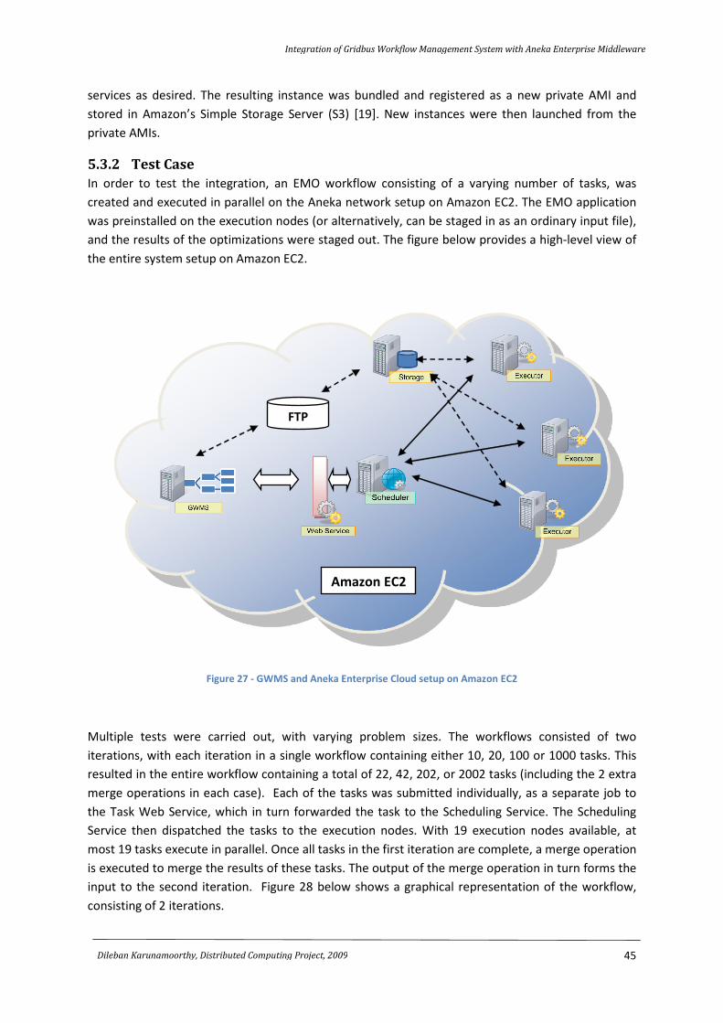
Integration of Gridbus Workflow Management System with Aneka Enterprise Middleware
45
Dileban Karunamoorthy, Distributed Computing Project, 2009
services as desired. The resulting instance was bundled and registered as a new private AMI and
stored in Amazon’s Simple Storage Server (S3) [19]. New instances were then launched from the
private AMIs.
5.3.2 Test Case
In order to test the integration, an EMO workflow consisting of a varying number of tasks, was
created and executed in parallel on the Aneka network setup on Amazon EC2. The EMO application
was preinstalled on the execution nodes (or alternatively, can be staged in as an ordinary input file),
and the results of the optimizations were staged out. The figure below provides a high-level view of
the entire system setup on Amazon EC2.
Figure 27 - GWMS and Aneka Enterprise Cloud setup on Amazon EC2
Multiple tests were carried out, with varying problem sizes. The workflows consisted of two
iterations, with each iteration in a single workflow containing either 10, 20, 100 or 1000 tasks. This
resulted in the entire workflow containing a total of 22, 42, 202, or 2002 tasks (including the 2 extra
merge operations in each case). Each of the tasks was submitted individually, as a separate job to
the Task Web Service, which in turn forwarded the task to the Scheduling Service. The Scheduling
Service then dispatched the tasks to the execution nodes. With 19 execution nodes available, at
most 19 tasks execute in parallel. Once all tasks in the first iteration are complete, a merge operation
is executed to merge the results of these tasks. The output of the merge operation in turn forms the
input to the second iteration. Figure 28 below shows a graphical representation of the workflow,
consisting of 2 iterations.
FTP
Amazon EC2
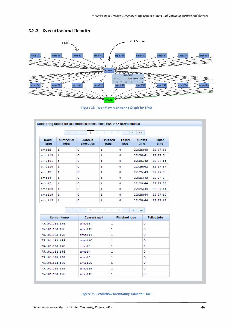
Integration of Gridbus Workflow Management System with Aneka Enterprise Middleware
46
Dileban Karunamoorthy, Distributed Computing Project, 2009
5.3.3 Execution and Results
Figure 28 - Workflow Monitoring Graph for EMO
Figure 29 - Workflow Monitoring Table for EMO
EMO EMO Merge
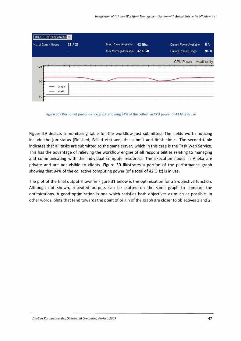
Integration of Gridbus Workflow Management System with Aneka Enterprise Middleware
47
Dileban Karunamoorthy, Distributed Computing Project, 2009
Figure 30 - Portion of performance graph showing 94% of the collective CPU power of 42 GHz in use
Figure 29 depicts a monitoring table for the workflow just submitted. The fields worth noticing
include the job status (Finished, Failed etc) and, the submit and finish times. The second table
indicates that all tasks are submitted to the same server, which in this case is the Task Web Service.
This has the advantage of relieving the workflow engine of all responsibilities relating to managing
and communicating with the individual compute resources. The execution nodes in Aneka are
private and are not visible to clients. Figure 30 illustrates a portion of the performance graph
showing that 94% of the collective computing power (of a total of 42 GHz) is in use.
The plot of the final output shown in Figure 31 below is the optimization for a 2-objective function.
Although not shown, repeated outputs can be plotted on the same graph to compare the
optimizations. A good optimization is one which satisfies both objectives as much as possible. In
other words, plots that tend towards the point of origin of the graph are closer to objectives 1 and 2.
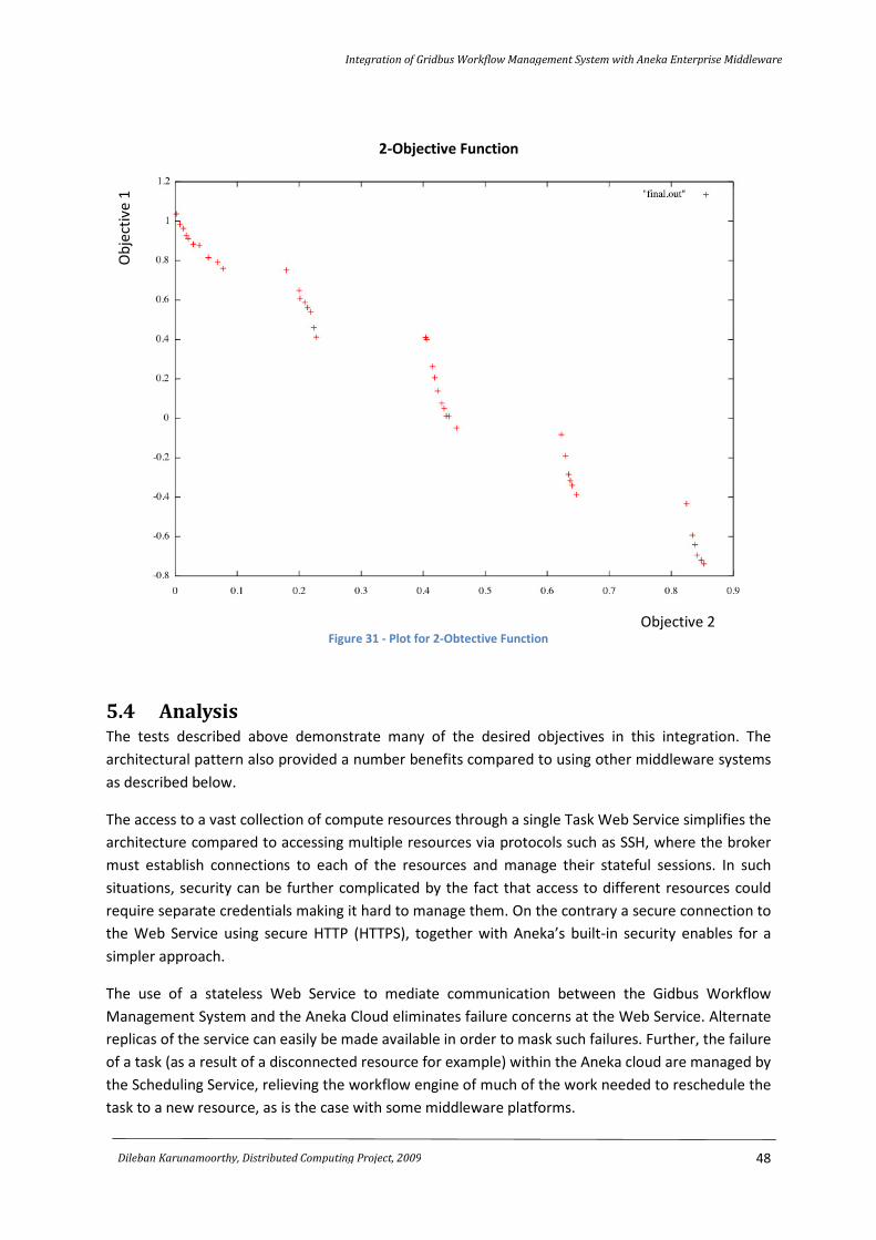
Integration of Gridbus Workflow Management System with Aneka Enterprise Middleware
48
Dileban Karunamoorthy, Distributed Computing Project, 2009
Figure 31 - Plot for 2-Obtective Function
5.4 Analysis The tests described above demonstrate many of the desired objectives in this integration. The
architectural pattern also provided a number benefits compared to using other middleware systems
as described below.
The access to a vast collection of compute resources through a single Task Web Service simplifies the
architecture compared to accessing multiple resources via protocols such as SSH, where the broker
must establish connections to each of the resources and manage their stateful sessions. In such
situations, security can be further complicated by the fact that access to different resources could
require separate credentials making it hard to manage them. On the contrary a secure connection to
the Web Service using secure HTTP (HTTPS), together with Aneka’s built-in security enables for a
simpler approach.
The use of a stateless Web Service to mediate communication between the Gidbus Workflow
Management System and the Aneka Cloud eliminates failure concerns at the Web Service. Alternate
replicas of the service can easily be made available in order to mask such failures. Further, the failure
of a task (as a result of a disconnected resource for example) within the Aneka cloud are managed by
the Scheduling Service, relieving the workflow engine of much of the work needed to reschedule the
task to a new resource, as is the case with some middleware platforms.
Ob
ject
ive
1
Objective 2
2-Objective Function

Integration of Gridbus Workflow Management System with Aneka Enterprise Middleware
49
Dileban Karunamoorthy, Distributed Computing Project, 2009
Another benefit of using a middleware platform like Aneka is the dynamic provisioning of resources
while a workflow is executing. While the only requirement to access compute resources is the URL to
the Task Web Service, additional execution nodes can be started on demand, shielding the workflow
engine from any responsibility in managing these new resources and scheduling tasks to them.
The scalability of the integration was amply demonstrated by submitting workflows with 2000 tasks.
While the integration does not impact the scalability of the Gridbus Workflow Management System
or Aneka Enterprise Middleware directly, the scalability in integrating the two technologies is
retained.
5.5 Summary This chapter began by discussing the tools and initial tests carried out during early development. It
then discussed the integration and verification tests performed on Amazon EC2. Details of setting up
and configuring the Gridbus Workflow Management System and Aneka Cloud on Amazon EC2 were
presented, followed by a discussion on the use the EMO optimization application to setup and test
workflows of varying sizes. The chapter ended with an analysis on the results and a look at some of
the advantages brought about as a result of this integration.

CHAPTER 666
Conclusion and Future Work
Chapter Contents:
6.1 Conclusion
6.2 Future Work
Integration of Gridbus Workflow Management System with Aneka Enterprise Middleware
51
Dileban Karunamoorthy, Distributed Computing Project, 2009
6.1 Conclusion The process of integrating different platforms requires a careful understanding of the technologies
involved. This is particularly so when the technologies involved are mature and based on well-
defined principles. The integration would not only require bridging the differences between the two
technologies, but the changes must also be coherent with the current principles, and the design
must fit in elegantly. On the contrary, a design that is short-sighted would lead a brittle solution that
would easily break as the two technologies evolve over time. This report presented a detailed study
on the design and implementation of integrating the Gridbus Workflow Management System with
Aneka Enterprise Middleware. The main components affected by this integration include the Aneka
plugin for the Gridbus Broker, the Task Web Service and the Scheduling and Storage services within
Aneka. The Task Web Service was central to the integration of the two platforms. It exposed Aneka’s
Task Programming Model as a service, making it accessible to clients written in technologies other
than .Net. The Task Web Service was based on a stateless model, as most Web Services are, and was
thus resilient to failure. The Aneka plugin for the Gridbus Broker provided the necessary bridging
between the workflow system and Aneka. Being a SOAP client to the Task Web Service, the plugin
translated all requests, from application creation to job submission and monitoring, into a series of
SOAP messages. Conceptual entities and states that had different semantics in the two platforms
were remapped. The behavior of the Scheduling and Storage services in Aneka were changed to
manage, among other things, the transfer of remote files. This integration now allows the Gridbus
Workflow Management System to take advantage of the rich set of features Aneka has to offer.
Some of these benefits including platform independence, dynamic provisioning of additional
services, scalability, and reduced overhead and administration as a result of interacting with a single
remote service to execute all tasks. In addition, a useful outcome of handling remote file transfers is
that existing .Net Aneka clients can now benefit from the use of files located remotely. The Task
Web Service also exposes Aneka to clients other than the Gridbus Workflow Management System.
The overall integration also helped discover many new issues that were previously overlooked. A
series of tests were subsequently carried out using real world applications in order to verify the
integration of the two platforms. The tests showed that the integration was seamless and fault-
tolerant.
6.2 Future Work As for future work, the work done on advance resource reservation for Aneka [14] using the
alternate offers protocol, can be integrated with the current solution in order to support various QoS
requirements. Although Aneka only supports the inherently unsecure FTP protocol for local and
remote file transfers, additional support for enabling more secure protocols such as SFTP and HTTPS
would be advantageous. The process of staging-in and staging-out files can be further streamlined by
allowing execution nodes to access files directly, by-passing the Storage Service. This however can
pose administrative challenges to users requiring more nodes to be exposed to the Internet. The
Thread and MapReduce Programming Models can also be exposed via new Web Services (or by
refactoring the existing Task Web Service) enabling fuller access to Aneka’s distinctive features. This
would make non-.Net clients have access to the same set of features currently available exclusively
to .Net clients.
Integration of Gridbus Workflow Management System with Aneka Enterprise Middleware
52
Dileban Karunamoorthy, Distributed Computing Project, 2009
REFERENCES
[1] S. Venugopal, K. Nadiminti, H. Gibbins, and R. Buyya, "Designing a Resource Broker for
Heterogeneous Grids," Software: Practice and Experience, vol. 38, pp. 793-825, July 10 2008.
[2] A. Luther, R. Buyya, R. Ranjan, and S. Venugopal, "Alchemi: A .NET-Based Enterprise Grid
Computing System," in Proceedings of the 6th International Conference on Internet
Computing, Las Vegas, USA, 2005.
[3] "The Globus Alliance". [Online]. Available: http://www.globus.org/. [Accessed: Jun. 3, 2009].
[4] "UNICORE - Distributed Computing and Data Resources". [Onlline]. Availeble: http://www.
unicore.eu/. [Accessed: Jun. 3, 2009].
[5] "Manjrasoft Pty Ltd: Cloud Computing Solutions". [Online]. Available: http://www.
manjrasoft.com. [Accessed: Jun. 7, 2009].
[6] S. Pandey, W. Voorsluys, M. Rahman, R. Buyya, J. Dobson, and K. Chiu, "A Grid Workflow
Environment for Brain Imaging Analysis on Distributed Systems," Concurrency and
Computation: Practice and Experience (to appear), 2009.
[7] J. Yu and R. Buyya, "A Novel Architecture for Realizing Grid Workflow using Tuple Spaces," in
Proceedings of the 5th IEEE/ACM International Workshop on Grid Computing, Pittsburgh,
USA, 2004.
[8] D. Gelernter, "Generative communication in Linda," ACM Transactions on Programming
Languages and Systems, vol. 7, pp. 80-112, 1985.
[9] IBM, "TSpaces - Computer Science Research at Almaden". Online. Available: http://www
.almaden.ibm.com /cs/tspaces/. [Accessed: Jun 8, 2009].
[10] J. Yu, S. Venugopal, and R. Buyya, "A Market-Oriented Grid Directory Service for Publication
and Discovery of Grid Service Providers and their Services," The Journal of Supercomputing,
vol. 36, pp. 17-31, April 2006.
[11] K. Czajkowski, S. Fitzgerald, I. Foster, and C. Kesselman, "Grid information services for
distributed resource sharing," in Proceedings of 10th IEEE International Symposium on High
Performance Distributed Computing, 2001.
[12] X. Chu, K. Nadiminti, C. Jin, S. Venugopal, and R. Buyya, "Aneka: Next-Generation Enterprise
Grid Platform for e-Science and e-Business Applications," in Proceedings of the 3rd IEEE
International Conference on e-Science and Grid Computing, Bangalore, India, 2007.
[13] S. Venugopal, X. Chu, and R. Buyya, "A Negotiation Mechanism for Advance Resource
Reservation using the Alternate Offers Protocol," in Proceedings of the 16th International
Workshop on Quality of Service, wente, The Netherlands, 2008.
[14] Y. Lai and R. Buyya, "Reservation Infrastructure," Technical Report, University of Melbourne
2009.
[15] "the Web Service, SOA and SOAP Testing Tool - soapUI". [Online]. Available:
http://www.soapui.org/. [Accessed: Jun 17, 2009]..
[16] A. S. Netto and C. Vecchiola, "Executing an Evolutionary Alogrithm in Multi-Cluster
Environments," Presentation Slides, 2009.
[17] " Amazon Elastic Compute Cloud (Amazon EC2)". Online. Available: http://aws.amazon.
com/ec2/. [Accessed: Jun 27, 2009].
[18] "Apache FtpServer,". [Online]. Available: http://mina.apache.org/ftpserver/. [Accessed: Jun
27, 2009].
[19] "Amazon Simple Storage Service (Amazon S3)". [Online]. Available: http://aws.amazon.com/
s3/. [Accessed: Jun 27, 2009].
Related Documents