IEPC-97-085 526 25th International Electric Propulsion Conference, August 24-28, 1997, Cleveland, Ohio Graphite Nozzle Performance Investigations with High Power Arcjets Martin Riehle, Helmut L. Kurtz, Frank Hammer and Monika Auweter-Kurt-z Institutfir Raumfahrtsysteme, Universit& Stuttgart Pfaffenwaldring 31, D-70550 Stuttgart, Germany phone: ++49-711-685-2394. far: ++49-711-685-3596 email: ep@. irs. uni-Stuttgart. de http://www. irs. uni-Stuttgart. de ABSTRACT The paper deals with the results of recent experiments that intended to investigate whether alternative high temperature materials besides tungsten i.e. carbon based materials could be used for future design studies and nozzle performance evaluation. The experiments used the high power radiation-cooled thermal arcjet thruster called HIPARC-R that has been designed and tested for the 100 kW power level. Operated with hydrogen as propellant, the baseline thruster has demonstrated a maximum specif;c impulse of 2050 in the past. An extensive test series has been performed with anode nozzles made offiber reinforced carbon based materials as well as of pure graphite. Detailed performance and thermal measurents were carried out to generate the validation dataset for numerical simulations. This means that the thermal analysis was focused on the backward calculation to determine the heat load that is deposited onto the nozzle as a distribution function. The results demonstrated that these materials couldprincipally be usedfor short term applications but also revealed that the operation limits were much lower concerning specific input power or special constrictor geometries. INTRODUCTION Thermal arcjet thrusters at low power levels have now been in use on space crafts for several years for north- south-station keeping ’ (NSSK) and will be deployed for primary propulsion on the P3-D radio amateur satellite early in fall 1997 ‘. In the US, an Air Force space demonstration, ESEX, will fly a 26 kW arcjet thruster ‘. Future applications of medium power arcjets may include orbit raising 4, repositioning, maneuvering, and drag compensation of large satellites and space stations. These first deployments of arcjets all use easily storable propellants, such as ammonia and hydrazine. The best specific impulse data with these propellants are relatively modest, ~800 s, Superior results can be achieved with hydrogen: hydrogen has an excellent specific heat capacity, which leads to better heat absorption of the propellant and hence the possibility to use regenerative heat transfer, and since the effective nozzle exit velocity is approximately proportional to the reciprocal value of the square root of the molecular mass, the theoretical highest specific impulse can also be expected. A disadvantage of hydrogen is the still not satisfyingly solved issue of storability. But this subject is under continual Copyright 0 1997 by the Electric Rocket Propulsion Society. All rights reserved. investigation 5 and substantial improvements are expected. However, many future space missions like platforms and stations will have substantial quantities of hydrogen on board. Especially the boil off from cryogenically stored hydrogen, which otherwise has to be dumped into space, could be used for propulsion purposes. Therefore, a new emphasis in the development of hydrogen arcjets has appeared in the last few years 6. For manned interplanetary missions, to Mars for example, high specific impulse at high thrust levels is required. Therefore, high power thrusters are under consideration for this purpose. High power in the range of some MW will be necessary for the mission to the planet which can be partly used for propulsion purposes during the cruise phase. Solar as well as nuclear thermal thrusters have been investigated for this purpose. The only propellant candidate for both thruster types is hydrogen and both are restricted to specific impulses below 800 s. If hydrogen is assured to be a propellant candidate, .much higher specific impulses can be achieved with hydrogen arcjets. In the case that the storage problem with hydrogen can not be satisfactorily solved for interplanetary missions in the near future, high power arcjets will also be able to be operated with ammonia. In this case, 800s

Welcome message from author
This document is posted to help you gain knowledge. Please leave a comment to let me know what you think about it! Share it to your friends and learn new things together.
Transcript
IEPC-97-085 526
25th International Electric Propulsion Conference, August 24-28, 1997, Cleveland, Ohio
Graphite Nozzle Performance Investigations with High Power Arcjets
Martin Riehle, Helmut L. Kurtz, Frank Hammer and Monika Auweter-Kurt-z Institutfir Raumfahrtsysteme, Universit& Stuttgart Pfaffenwaldring 31, D-70550 Stuttgart, Germany
phone: ++49-711-685-2394. far: ++49-711-685-3596 email: ep@. irs. uni-Stuttgart. de http://www. irs. uni-Stuttgart. de
ABSTRACT
The paper deals with the results of recent experiments that intended to investigate whether alternative high
temperature materials besides tungsten i.e. carbon based materials could be used for future design studies and nozzle performance evaluation. The experiments used the high power radiation-cooled thermal arcjet thruster called
HIPARC-R that has been designed and tested for the 100 kW power level. Operated with hydrogen as propellant,
the baseline thruster has demonstrated a maximum specif;c impulse of 2050 in the past. An extensive test series has
been performed with anode nozzles made offiber reinforced carbon based materials as well as of pure graphite. Detailed performance and thermal measurents were carried out to generate the validation dataset for numerical
simulations. This means that the thermal analysis was focused on the backward calculation to determine the heat
load that is deposited onto the nozzle as a distribution function.
The results demonstrated that these materials couldprincipally be usedfor short term applications but also revealed
that the operation limits were much lower concerning specific input power or special constrictor geometries.
INTRODUCTION Thermal arcjet thrusters at low power levels have now been in use on space crafts for several years for north- south-station keeping ’ (NSSK) and will be deployed for primary propulsion on the P3-D radio amateur satellite early in fall 1997 ‘. In the US, an Air Force space demonstration, ESEX, will fly a 26 kW arcjet thruster ‘. Future applications of medium power arcjets may include orbit raising 4, repositioning, maneuvering, and drag compensation of large satellites and space stations. These first deployments of arcjets all use easily storable propellants, such as ammonia and hydrazine. The best specific impulse data with these propellants are relatively modest, ~800 s, Superior results can be achieved with hydrogen: hydrogen has an excellent specific heat capacity, which leads to better heat absorption of the propellant and hence the possibility to use regenerative heat transfer, and since the effective nozzle exit velocity is approximately proportional to the reciprocal value of the square root of the molecular mass, the theoretical highest specific impulse can also be expected. A disadvantage of hydrogen is the still not satisfyingly solved issue of storability. But this subject is under continual Copyright 0 1997 by the Electric Rocket Propulsion Society. All rights reserved.
investigation 5 and substantial improvements are expected. However, many future space missions like platforms and stations will have substantial quantities of hydrogen on board. Especially the boil off from cryogenically stored hydrogen, which otherwise has to be dumped into space, could be used for propulsion purposes. Therefore, a new emphasis in the development of hydrogen arcjets has appeared in the last few years 6. For manned interplanetary missions, to Mars for example, high specific impulse at high thrust levels is required. Therefore, high power thrusters are under consideration for this purpose. High power in the range of some MW will be necessary for the mission to the planet which can be partly used for propulsion purposes during the cruise phase. Solar as well as nuclear thermal thrusters have been investigated for this purpose. The only propellant candidate for both thruster types is hydrogen and both are restricted to specific impulses below 800 s. If hydrogen is assured to be a propellant candidate, .much higher specific impulses can be achieved with hydrogen arcjets. In the case that the storage problem with hydrogen can not be satisfactorily solved for interplanetary missions in the near future, high power arcjets will also be able to be operated with ammonia. In this case, 800s
IEPC-97-085 527
specific impulse can be expected but with significant savings in the propellant storage mass compared with solar and nuclear thermal thrusters. Therefore, at the Institute for Space Systems (IRS = Institut filr Raumfahrtsysteme) at Stuttgart University the development of high power arcjets in the range of 100 kW was initiated in 1988 ‘. The program was largely experimental with analytical and numerical work providing guidance and comprehension.
Objectives of the Project
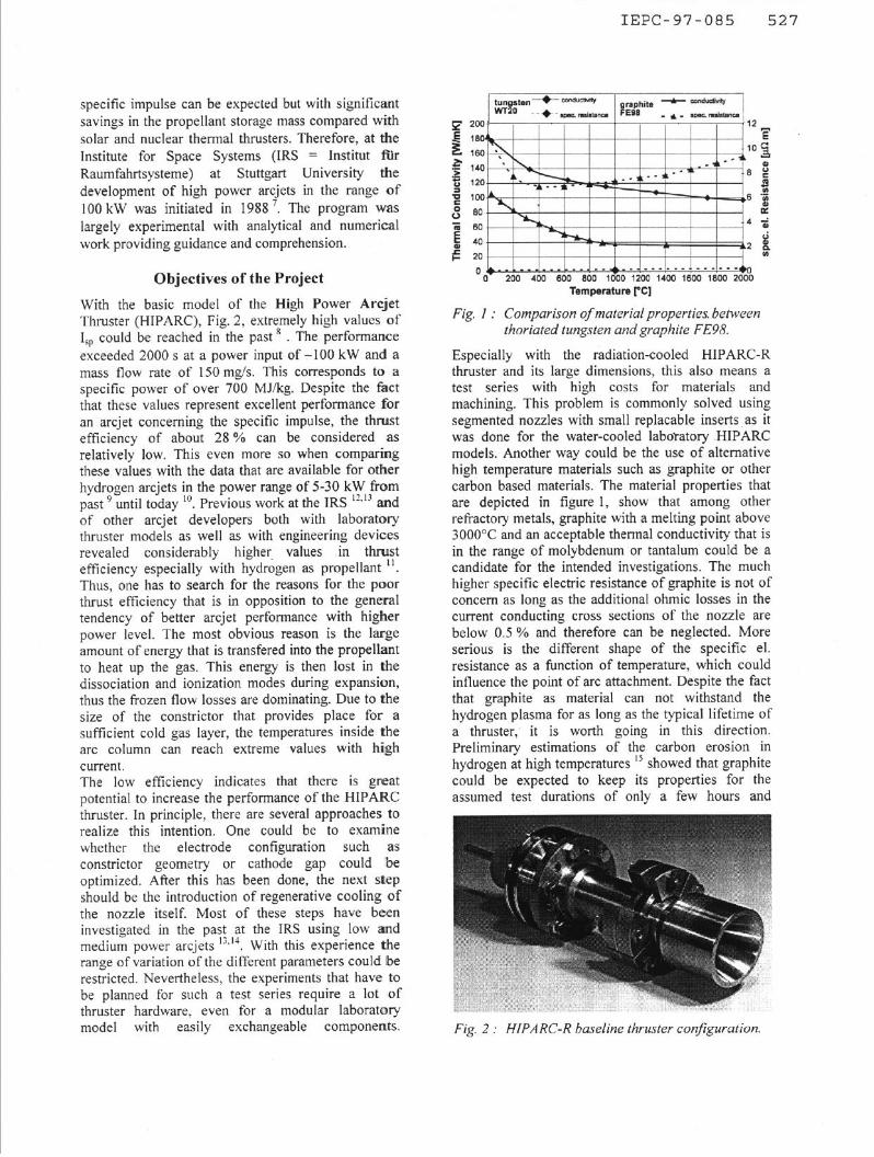
With the basic model of the High Power Arcjet Thruster (HIPARC), Fig. 2, extremely high values of I,, could be reached in the past a . The performance exceeded 2000 s at a power input of -100 kW and a mass flow rate of I50 mg/s. This corresponds to a specific power of over 700 MJikg. Despite the fact that these values represent excellent performance for an arcjet concerning the specific impulse, the thrust efficiency of about 28 % can be considered as relatively low. This even more so when comparing these values with the data that are available for other hydrogen arcjets in the power range of 5-30 kW from past 9 until today ‘“. Previous work at the IRS “,” and of other arcjet developers both with laboratory thruster models as well as with engineering devices revealed considerably higher. values in thrust efficiency especially with hydrogen as propellant ‘I. Thus, one has to search for the reasons for the poor thrust efficiency that is in opposition to the general tendency of better arcjet performance with higher power level. The most obvious reason is the large amount of energy that is transfered into the propellant to heat up the gas. This energy is then lost in the dissociation and ionization modes during expansion, thus the frozen flow losses are dominating. Due to the size of the constrictor that provides place for a sufficient cold gas layer, the temperatures inside the arc column can reach extreme values with hish current. The low efficiency indicates that there is great potential to increase the performance of the .HIPARC thruster. In principle, there are several approaches to realize this intention. One could be to examine whether the electrode configuration such as constrictor geometry or cathode gap could be optimized. After this has been done, the next step should be the introduction of regenerative cooling of the nozzle itself. Most of these steps have been investigated in the past at the IRS using low and medium power arcjets ‘ZM With this experience the range of variation of the different parameters could be restricted. Nevertheless, the experiments that have to be planned for such a test series require a lot ,of thruster hardware, even for a modular laboratory model with easily exchangeable components.
c E-
140 ‘.I---- ’ ’ 8
6
SO
SO 4
40 2 20
0 ._L.._,_..L __,.. .A .-,-.-,...i _..--. I +o 200 400 600 BOO 1600 1200 1400 1500 1800 2000
Temperature PC]
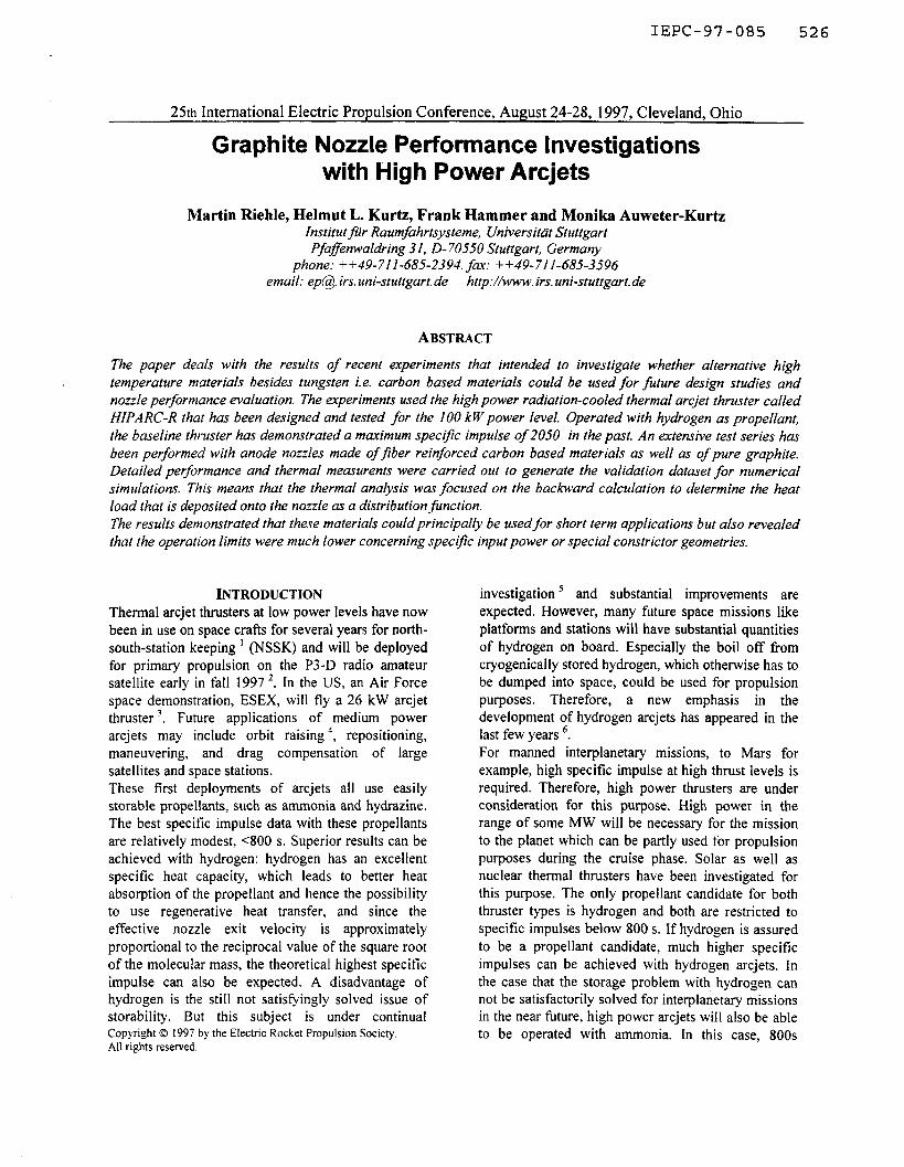
Fig. 1 : Comparison of materialproperties between thoriated tungsten and graphite FE98
Especially with the radiation-cooled HIPARC-R thruster and its large dimensions, this also means a test series with high costs for materials and machining. This problem is commonly solved using segmented nozzles with small replacable inserts, as it was done for the water-cooled laboyatory .HIPARC models. Another way could be the use of alternative high temperature materials such as graphite or other carbon based materials. The material properties that are depicted in figure 1, show that among other refractory metals, graphite with a melting point above 3000°C and an acceptable thermal conductivity that is in the range of molybdenum or tantalum could be a candidate for the intended investigations. The much higher specific electric resistance of graphite is not of concern as long as the additional ohmic losses in the current conducting cross sections of the nozzle are below 0.5 % and therefore can be neglected. More serious is the different shape of the specific el. resistance as a function of temperature, which could influence the point of arc attachment. Despite the fact that graphite as material can not withstand the hydrogen plasma for as long as the typical lifetime of a thruster, it is worth going in this direction. Preliminary estimations of the carbon erosion in hydrogen at high temperatures I5 showed that graphite could be expected to keep its properties for the assumed test durations of only a few hours and
Fig. 2 : HIPARC-R baseline thruster conjiguration.
IEPC-97-085 528
surface temperatures up to 2000°C. _25r- mass flow rate: 150 mg/s H2 -.
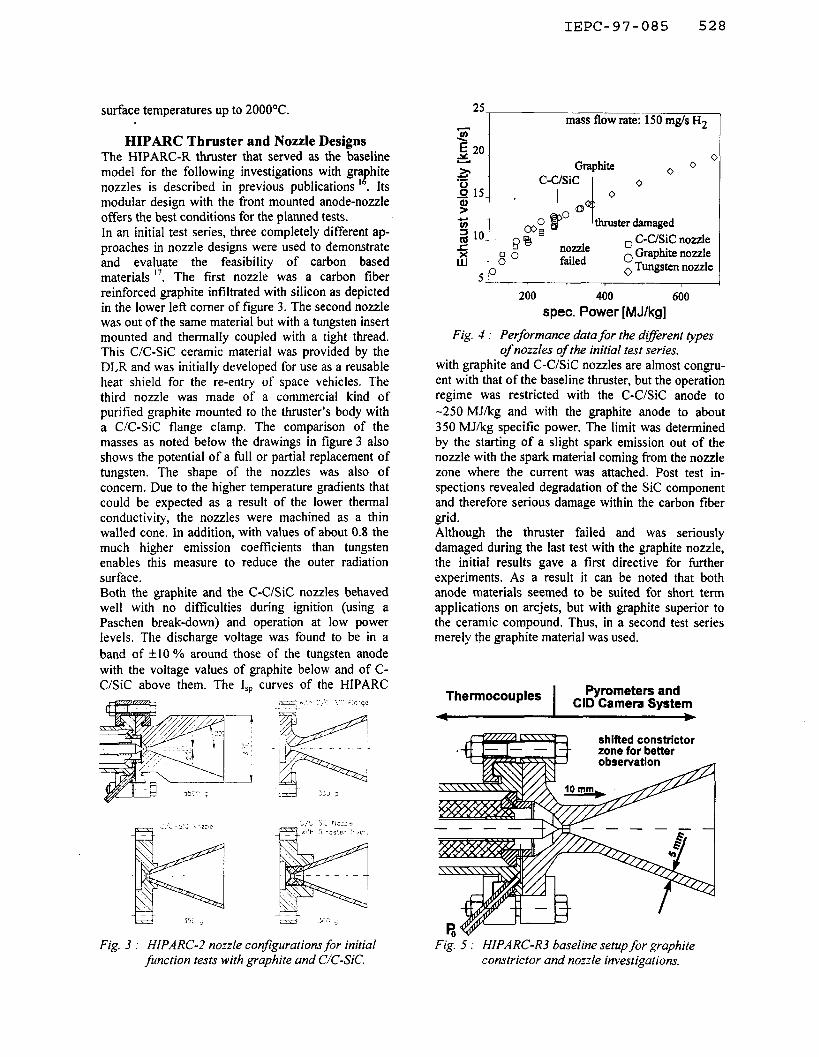
HIPARC Thruster and Nozzle Designs The HIPARC-R thruster that served as the baseline model for the following investigations with gra hite
,! nozzles is described in previous publications . Its modular design with the front mounted anode-nozzle offers the best conditions for the planned tests. In an initial test series, three completely different ap- proaches in nozzle designs were used to demonstrate and evaluate the feasibility of carbon based materials “. The first nozzle was a carbon fiber reinforced graphite infiltrated with silicon as depicted in the lower left comer of figure 3. The second nozzle was out of the same material but with a tungsten insert mounted and thermally coupled with a tight thread. This C/C-Sic ceramic material was provided by the DLR and was initially developed for use as a reusable heat shield for the re-entry of space vehicles. The third nozzle was made of a commercial kind of purified graphite mounted to the thruster’s body with a C/C-Sic flange clamp. The comparison of the masses as noted below the drawings in figure 3 also shows the potential of a full or partial replacement of tungsten. The shape of the nozzles was also of concern. Due to the higher temperature gradients that could be expected as a result of the lower thermal conductivity, the nozzles were machined as a thin walled cone. In addition, with values of about 0.8 the much higher emission coefficients than tungsten enables this measure to reduce the outer radiation surface. Both the graphite and the C-C/Sic nozzles behaved well with no difficulties during ignition (using a Paschen break-down) and operation at low power levels. The discharge voltage was found to be in a band of +_I0 % around those of the tungsten anode with the voltage values of graphite below and of C- C/Sic above them. The I,, curves of the HIPARC
7
:.: -1
-l
Fig. 3 : HIPARC- nozzle configurations for initial Fig. 5 : HIPARC-R3 baseline setup for graphite function tests with graphite and C/C-SC. constrictor and nozzle investigations.
200 400 600 spec. Power [M J/kg]
Fig. 4 : Performance data for the different rypes of nozzles of the initial test series.
with graphite and C-C/Sic nozzles are almost congru- ent with that of the baseline thruster, but the operation regime was restricted with the C-C/Sic anode to -250 MJ/kg and with the graphite anode to about 350 MJ/kg specific power. The limit was determined by the starting of a slight spark emission out of the nozzle with the spark material coming from the nozzle zone where the current was attached. Post test in- spections revealed degradation of the Sic component and therefore serious damage within the carbon fiber grid. Although the thruster failed and was seriously damaged during the last test with the graphite nozzle, the initial results gave a first directive for further experiments. As a result it can be noted that both anode materials seemed to be suited for short term applications on arcjets, but with graphite superior to the ceramic compound. Thus, in a second test series merely the graphite material was used.
Thermocouples I
Pyrometers and CID Camera System
I b
shifted constrictor zone for better
IEPC-97-085 529
I_
7
&I& = 225 hble I: Overview oj investigated nozzle geometries.
nozzle HPR_340
HPR_350
HPR 360 Bi-ex? 1 la=5mm a = 5” HPR 370 Bi-ex? 2 l,=lOmm a= 10" HPR_380
geometry d,=3mm I,=3mm
A&& = 400 d,=4mm I,=4mm
WAC = 225 d,=4mm I,=4mm
A& = 225 d,=4mm I,=4mm
A&& = 225 d,=4mm I,=8mm
schematic
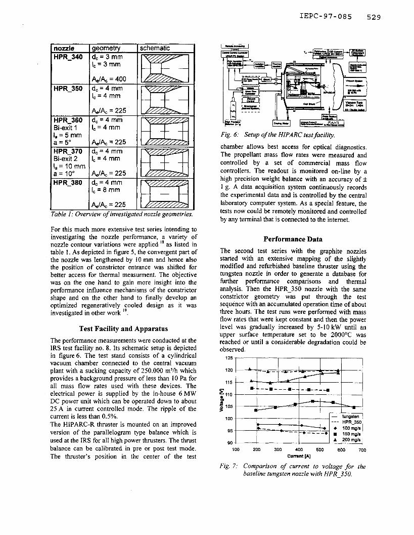
For this much more extensive test series intending to investigating the nozzle performance, a variety of nozzle contour variations were applied ‘* as listed in table 1. As depicted in figure 5, the convergent part of the nozzle was lengthened by 10 mm and hence also the position of constrictor entrance was shifted for better access for thermal measurment. The objective was on the one hand to gain more insight into the performance influence mechanisms of the constrictor shape and on the other hand to finally develop an optimized regeneratively cooled design as it was investigated in other work 19.
Test Facility and Apparatus
The performance measurements were conducted at the IRS test facility no. 8. Its schematic setup is depicted in figure 6. The test stand consists of a cylindrical vacuum chamber connected to the central vacuum plant with a sucking capacity of 250.000 m3/h which provides a background pressure of less than 10 Pa for all mass flow rates used with these devices. The electrical power is supplied by the in-house 6 MW DC power unit which can be operated down to about 25 A in current controlled mode. The ripple of the current is less than 0.5%. The HIPARC-R thruster is mounted on an improved version of the parallelogram type balance which is used at the IRS for all high power thrusters. The thrust balance can be calibrated in pre or post test mode. The thruster’s position in the center of the test
Fig. 6: Setup of the HIPARC test facility.
chamber allows best access for optical diagnostics. The propellant mass flow rates were measured and controlled by a set of commercial mass flow controllers. The readout is monitored on-line by a high precision weight balance with an accuracy off 1 g. A data acquisition system continuously records the experimental data and is controlled by the central laboratory computer system. As a special feature, the tests now could be remotely mbnitored and controlled by any terminal that is connected to the intemet.
Performance Data
The second test series with the graphite nozzles started with an extensive mapping of the slightly modified and refurbished baseline thruster using the tungsten nozzle in order to generate a database for further performance comparisons and thermal analysis. Then the HPR_350 nozzle with the same constrictor geometry was put through the test sequence with an accumulated operation time of about three hours. The test runs were performed with mass flow rates that were kept constant and then the power level was gradually increased by 5-10 kW until an upper surface temperature set to be 2000°C was reached or until a considerable degradation could be observed.
125 j--- I I I I I
E 8. --=---*- -+- -4 ~ 110 1
I I I I I i3
z 0 105 >
Fig. 7: Comparison of current to voltage for the baseline tungsten nozzle with HPR_350.
IEPC-97-085 530
15 25 35 45 55
Input Power [kw]
65 75
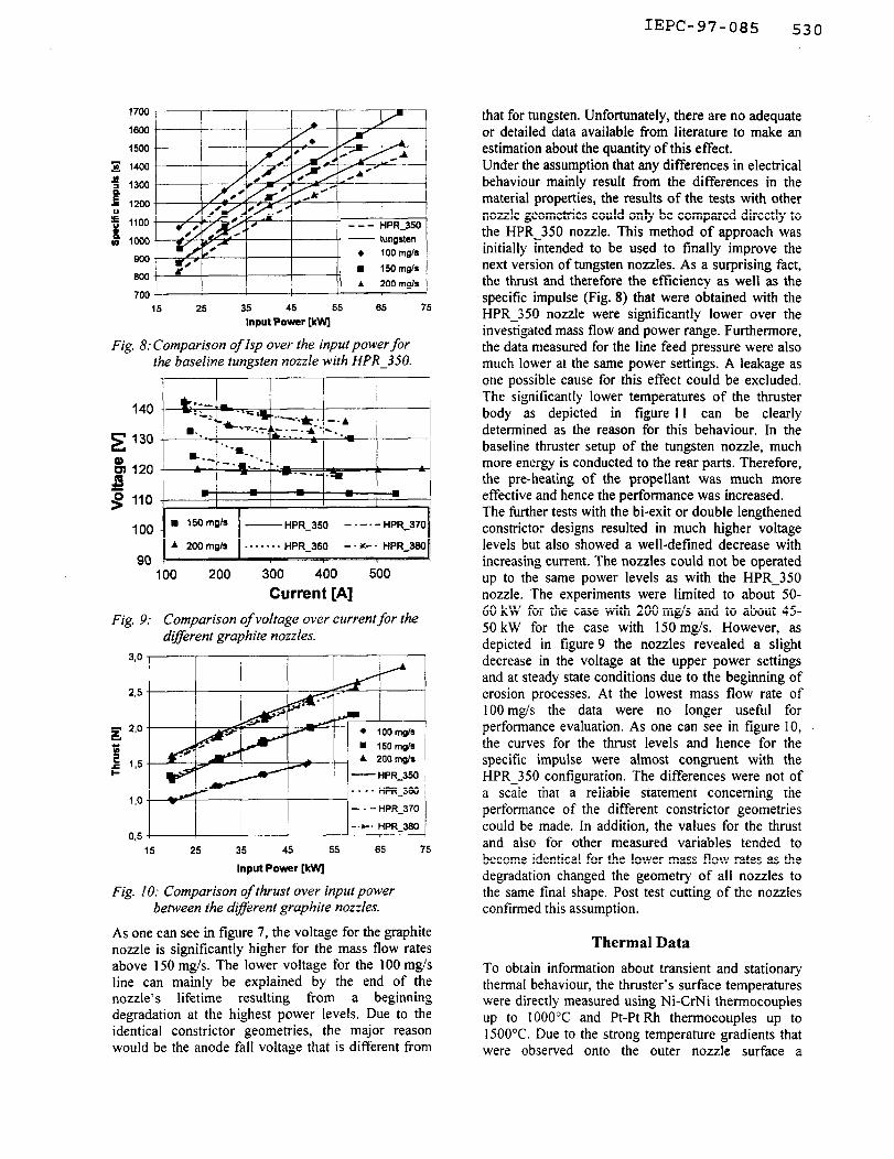
Fig. 8: Comparison of Isp over the input power for the baseline tungsten nozzle with HPR_350.
1 I I I I
140
E 130
& 120 ,s g 110
100 - HPR_350 - . -. - HPR_370
90 100 200 300 400 500
Current [A]
Fig. 9: Comparison of voItage over currentfor the different graphite nozzles.
3.0
23
I,0
-.x-. HPR_360 0.5
15 25 35 45 55 65 75
Input Power [kw
Fig. IO: Comparison of thrust over input power between the dyerent graphite nozzles.
As one can see in figure 7, the voltage for the graphite nozzle is significantly higher for the mass flow rates above 150 mgs. The lower voltage for the 100 mg/s line can mainly be explained by the end of the nozzle’s lifetime resulting from a beginning degradation at the highest power levels. Due to the identical constrictor geometries, the major reason would be the anode fall voltage that is different from
that for tungsten. Unfortunately, there are no adequate or detailed data available from literature to make an estimation about the quantity of this effect. Under the assumption that any differences in electrical behaviour mainly result from the differences in the material properties, the results of the tests with other nozzle geometries could only be compared directly to the HPR 350 nozzle. This method of approach was initially intended to be used to finally improve the next version of tungsten nozzles. As a surprising fact, the thrust and therefore the efficiency as well as the specific impulse (Fig. 8) that were obtained with the HPR 350 nozzle were significantly lower over the invesiigated mass flow and power range. Furthermore, the data measured for the line feed pressure were also much lower at the same power settings. A leakage as one possible cause for this effect could be excluded. The significantly lower temperatures of the thruster body as depicted in figure 11 can be clearly determined as the reason for this behaviour. In the baseline thruster setup of the tungsten nozzle, much more energy is conducted to the rear parts. Therefore, the pre-heating of the propellant was much more effective and hence the performance was increased. The further tests with the bi-exit or double lengthened constrictor designs resulted in much higher voltage levels but also showed a well-defined decrease with increasing current. The nozzles could not be operated up to the same power levels as with the HPR_350 nozzle. The experiments were limited to about 50- 60 kW for the case with 200 mg/s and to about 45- 50 kW for the case with 150 mg/s. However, as depicted in figure 9 the nozzles revealed a slight decrease in the voltage at the upper power settings and at steady state conditions due to the beginning of erosion processes. At the lowest mass flow rate of 100 mgs the data were no longer useful for performance evaluation. As one can see in figure 10, the curves for the thrust levels and hence for the specific impulse were almost congruent with the HPR_350 configuration. The differences were not of a scale that a reliable statement concerning the performance of the different constrictor geometries could be made. In addition, the values for the thrust and also for other measured variables tended to become identical for the lower mass flow rates as the degradation changed the geometry of all nozzles to the same final shape. Post test cutting of the nozzles confirmed this assumption.
Thermal Data
To obtain information about transient and stationary thermal behaviour, the thruster’s surface temperatures were directly measured using Ni-CrNi thermocouples up to 1OOO’C and Pt-Pt Rh thermocouples up to 1500°C. Due to the strong temperature gradients that were observed onto the outer nozzle surface a
IEPC-97-085 53:1
pyrometer was used to monitor the area of maximum temperatures that was shifted backwards with increasing power settings. The emissivity of the pure tungsten surface of the baseline nozzle was set to about 0.3-0.35, whereas values of 0.8-0.85 were used for,the high emissivity C/C-Sic and for graphite.
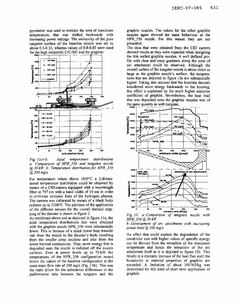
Fig. I la+b: Axial temperature distributions a: Comparison of HPR_350 and tungsten nozzle @ 30 kW b: Temperature distribution for HPR_350 @ 200 mgls.
For temperature values above 105O’C a 2-dimen- sional temperature distribution could be obtained by means of a CID-camera equipped with a wavelength filter at 797 nm with a band width of 10 nm in order to eliminate emission lines of the hydrogen plasma. The camera was calibrated by means of a black body radiator up to 2200°C. The partition of the application of the different sensors for the overall thermal map- ping of the thruster is shown in figure 3. As mentioned above and as depicted in figure 1 la, the axial temperature distributions that were obtained with the graphite nozzle HPR_350 were substantially lower. This is because of a much lower heat transfer rate from the nozzle to the thruster’s body resulting from the smaller cross sections and also from the lower thermal conductivity. Thus, more energy that is deposited onto the nozzle is radiated off the nozzle surfaces. Even at power levels up to 70 kW the temperatures of the HPR_350 configuration rested below the values of the baseline configuration at the same mass flow rate of 200 mg/s (Fig. 11 b). This was the main driver for the substantial differences in the performance data between the tungsten and the
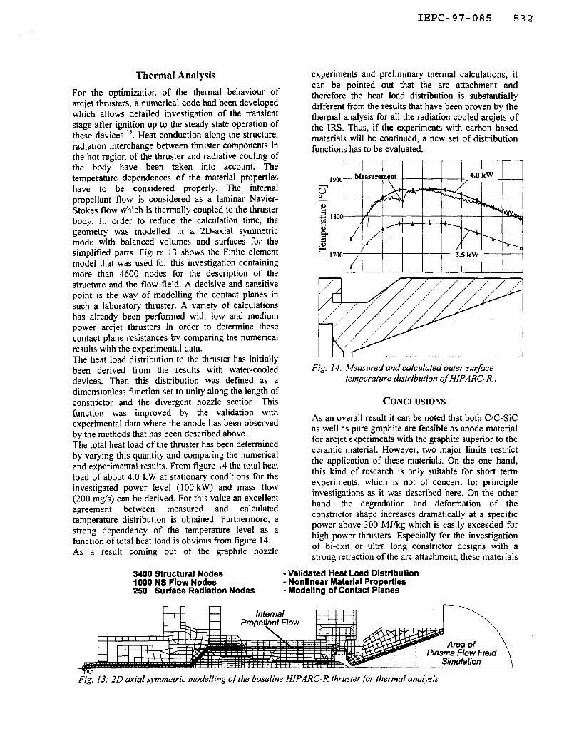
graphite nozzles. The values for the other graphite nozzles again showed the same behaviour as the HPR_350 nozzle. For this reason they are not presented. The data that were obtained from the CID camera showed results as they were expected when designing the thin walled graphite nozzles. A well defined pro- file with clear and steep gradients along the zone of arc attachment could be observed. Although the overall surface of the tungsten nozzle is about twice as large as the graphite nozzle’s surface, the tempera- tures that are depicted in figure 12a are substantially higher. Taking into account that the baseline thruster transferred more energy backwards to the housing, this effect is explained by the much higher emission coefftcient of graphite. Nevertheless, the heat load that was deposited onto the graphite nozzles was of the same quantity as with tungsten.
Fig. 12: a: Comparison oj tungsteq nozzle with HPR_350 @ 30 k W. 6: Development of arc attachment with increasing power level @ 200 mg/s.
An effect that could explain the degradation of the constrictor exit with higher values of specific energy can be derived from the retraction of the maximum temperature and hence the retraction of the arc attachment itself as it is depicted in figure 12b. This results in a dramatic increase of the heat flux until the boundaries in material properties of graphite are exceeded. A limitation of about 300 MJ/kg was determined for this kind of short term application of graphite.
IEPC-97-085 532
Thermal Analysis
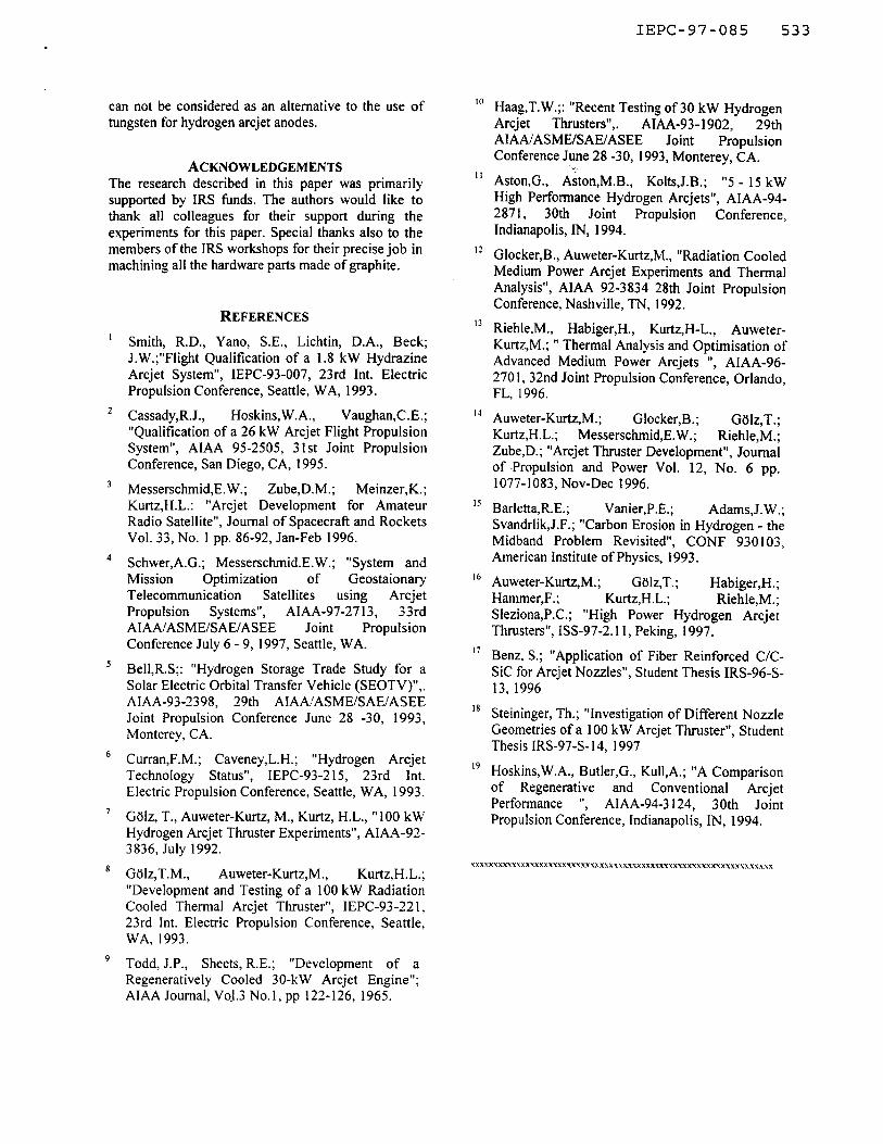
For the optimization of the thermal behaviour of arcjet thrusters, a numerical code had been developed which allows detailed investigation of the transient stage after ignition up to the steady state operation of these devices “. Heat conduction along the structure, radiation interchange between thruster components in the hot region of the thruster and radiative cooling of the body have been taken into account. The temperature dependences of the material properties have to be considered properly. The internal propellant flow is considered as a laminar Navier- Stokes flow which is thermally coupled to the thruster body. In order to reduce the calculation time, the geometry was modelled in a 2D-axial symmetric mode with balanced volumes and surfaces for the simplified parts. Figure 13 shows the Finite element model that was used for this investigation containing more than 4600 nodes for the description of the structure and the flow field. A decisive and sensitive point is the way of modelling the contact planes in such a laboratory thruster. A variety of calculations has already been performed with low and medium power arcjet thrusters in order to determine these contact plane resistances by comparing the numerical results with the experimental data. The heat load distribution to the thruster has initially been derived from the results with water-cooled devices. Then this distribution was defined as a dimensionless function set to unity along the length of constrictor and the divergent nozzle section. This function was improved by the validation with experimental data where the anode has been observed by the methods that has been described above. The total heat load of the thruster has been determined by varying this quantity and comparing the numerical and experimental results. From figure, 14 the total heat load of about 4.0 kW at stationary conditions for the investigated power level (100 kW) and mass flow (200 mg/s) can be derived. For this value an excellent agreement between measured and calculated temperature distribution is obtained. Furthermore, a strong dependency of the temperature level as a function of total heat load is obvious from figure 14. As a result coming out of the graphite nozzle
experiments and preliminary thermal calculations, it can be pointed out that the arc attachment and therefore the heat load distribution is substantially different from the results that have been proven by the thermal analysis for all the radiation cooled arcjets of the IRS. Thus, if the experiments with carbon based materials will be continued, a new set of distribution functions has to be evaluated.
Fig. 14: Measured and calculated outer surface temperature distribution of HIPARC-R..
CONCLUSIONS
As an overall result it can be noted that both C/C-Sic as well as pure graphite are feasible as anode material for arcjet experiments with the graphite superior to the ceramic material. However, two major limits restrict the application of these materials. On the one hand, this kind of research is only suitable for short term experiments, which is not of concern for principle investigations as it was described here. On the other hand, the degradation and deformation of the constrictor shape increases dramatically at a specific power above 300 MJ/kg which is easily exceeded for high power thrusters. Especially for the investigation of bi-exit or ultra long constrictor designs with a strong retraction of the arc attachment, these materials
3400 Structural Nodes -Validated Heat Load Distribution 1000 NS Flow Nodes - Nonlinear Material Properties 250 Surface Radiation Nodes - Modeling of Contact Planes
Fig, 13: 2D axial symmetric modelling of the baseline HIPARC-R thruster for thermal analysis.
IEPC-97-085 533
can not be considered as an alternative to the use of tungsten for hydrogen arcjet anodes.
ACKNOWLEDGEMENTS The research described in this paper was primarily supported by IRS funds. The authors would like to thank all colleagues for their support during the experiments for this paper. Special thanks also to the members of the IRS workshops for their precise job in machining all the hardware parts made of graphite.
REFERENCES
’ Smith, R.D., Yano, S.E., Lichtin, D.A., Beck; J.W.;“Flight Qualification of a 1.8 kW Hydrazine Arcjet System”, IEPC-93-007, 23rd Int. Electric Propulsion Conference, Seattle, WA, 1993.
’ Cassady,R.J., Hoskins,W.A., Vaughan,C.E.; “Qualification of a 26 kW Arcjet Flight Propulsion System”, AIAA 95-2505, 3 1st Joint Propulsion Conference, San Diego, CA, 1995.
3 Messerschmid,E. W.; Zube,D.M.; Meinzer,K.; Kurtz,H.L.: “Arcjet Development for Amateur Radio Satellite”, Journal of Spacecraft and Rockets Vol. 33, No. 1 pp. 86-92, Jan-Feb 1996.
4 Schwer,A.G.; Messerschmid.E.W.; “System and Mission Optimization of Geostaionary Telecommunication Satellites using Arcjet Propulsion Systems”, AIAA-97-27 13, 33rd AIAAIASMEISAEIASEE Joint Propulsion Conference July 6 - 9, 1997, Seattle, WA.
5 Bel1,R.S;: “Hydrogen Storage Trade Study for a Solar Electric Orbital Transfer Vehicle (SEOTV)“,. AIAA-93-2398, 29th AIAAIASMEISAEIASEE Joint Propulsion Conference June 28 -30, 1993, Monterey, CA.
6 Curran,F.M.; Caveney,L.H.; “Hydrogen Arcjet Technology Status”, IEPC-93-215, 23rd Int. Electric Propulsion Conference, Seattle, WA, 1993.
’ Gdlz, T., Auweter-Kurtz, M., Kurtz, H.L., “100 kW Hydrogen Arcjet Thruster Experiments”, AIAA-92- 3836, July 1992.
* Gblz,T.M., Auweter-Kurtz,M., Kurtz,H.L.; “Development and Testing of a 100 kW Radiation Cooled Thermal Arcjet Thruster”, IEPC-93-22 1, 23rd Int. Electric Propulsion Conference, Seattle, WA, 1993.
9 Todd, J.P., Sheets, R.E.; “Development of a Regeneratively Cooled 30-kW Arcjet Engine”; AIAA Journal, VoJ.3 No.1, pp 122-126, 1965.
IO
Ii
12
13
I4
I5
16
17
18
19
Haag,T.W.;: “Recent Testing of 30 kW Hydrogen Arcjet Thrusters”,. AIAA-93- 1902, 29th AIAAfASME/SAE/ASEE Joint Propulsion Conference June 28 -30, 1993, Monterey, CA.
AstonG., Aiton,M.B., Kolts,J.B.; “5 - 15 kW High Performance Hydrogen Arcjets”, A&4-94- 2871, 30th Joint Propulsion Conference, Indianapolis, IN, 1994.
Glocker,B., Auweter-Kurtz,M., “Radiation Cooled Medium Power Arcjet Experiments and Thermal Analysis”, AIAA 92-3834 28th Joint Propulsion Conference, Nashville, TN, 1992.
Riehle,M., Habiger,H., Kurtz,H-L., Auweter- Kurtz,M.; ” Thermal Analysis and Optimisation of Advanced Medium Power Arcjets ‘I, AIAA-96- 270 I, 32nd Joint Propulsion Conference, Orlando, FL, 1996.
Auweter-Kurtz,M.; Glocker,B.; GUlz,T.; Kurtz,H.L.; Messerschmid,E.W.; Riehle,M.; Zube,D.; “Arcjet Thruster Development”, Journal of .Propulsion and Power Vol. 12, No. 6 pp. 1077-1083, Nov-Dee 1996.
Barletta,R.E.; Vanier,P. E.; Adams,J.W.; Svandrlik,J.F.; “Carbon Erosion in Hydrogen - the Midband Problem Revisited”, CONF 930103, American Institute of Physics, 1993.
Auweter-Kurtz,M.; Golz,T.; Habiger,H.; Hammer,F.; Kurtz,H.L.; Riehle,M.; Sleziona,P.C.; “High Power Hydrogen Arcjet Thrusters”, ISS-97-2.11, Peking, 1997.
Benz, S.; “Application of Fiber Reinforced C/C- Sic for Arcjet Nozzles”, Student Thesis IRS-96-S- 13, 1996
Steininger, Th.; “Investigation of Different Nozzle Geometries of a 100 kW Arcjet Thruster”, Student Thesis IRS-97-S- 14, 1997
Hoskins,W.A., Butler,G., Kull,A.; “A Comparison of Regenerative and Conventional Arcjet Performance ‘I, AIAA-94-3 124, 30th Joint Propulsion Conference, Indianapolis, IN, 1994.
Related Documents