HT503 User Manual www.grandstream.com Firmware Version 1.0.1.41 [email protected] Grandstream Networks, Inc. HT503 FXS/FXO Port Analog Telephone Adaptor

Welcome message from author
This document is posted to help you gain knowledge. Please leave a comment to let me know what you think about it! Share it to your friends and learn new things together.
Transcript

HT503 User Manual www.grandstream.com Firmware Version 1.0.1.41 [email protected]
Grandstream Networks, Inc. HT503 FXS/FXO Port Analog Telephone Adaptor
Grandstream Networks, Inc. HT503 User Manual Page 2 of 37 Firmware 1.0.1.41 Last Updated: 8/2009
TABLE OF CONTENTS HT503 USER MANUAL
WELCOME....................................................................................................................................................... 4
Safety Compliances ................................................................................................................ 4 Warranty ................................................................................................................................. 4
CONNECT YOUR HT503................................................................................................................................... 5 Equipment Packaging ................................................................................................................. 5 Connecting the HT503................................................................................................................ 5
PRODUCT OVERVIEW....................................................................................................................................... 7 Software Features Overview....................................................................................................... 7 Hardware Specification............................................................................................................... 8
BASIC OPERATIONS ........................................................................................................................................ 9 Understanding HT503 Voice Prompt ......................................................................................... 9 Placing a Phone Call ................................................................................................................. 10
Phone or Extension Numbers................................................................................................ 10 Direct IP Calls....................................................................................................................... 10
Call Hold................................................................................................................................... 11 Call Waiting .............................................................................................................................. 11 Call Transfer ............................................................................................................................. 11
Blind Transfer ....................................................................................................................... 11 Attended Transfer ................................................................................................................. 12
3-way Conferencing.................................................................................................................. 12 PSTN Pass Through.................................................................................................................. 12 VoIP-to-PSTN Calls ................................................................................................................. 13 PSTN-to-VoIP Calls ................................................................................................................. 13 Route Calls to PSTN................................................................................................................. 14 Forward Calls to PSTN............................................................................................................. 14 Forward Calls to VoIP .............................................................................................................. 15 One Stage Dialing ..................................................................................................................... 15 Fax Support............................................................................................................................... 15
CALL FEATURES ........................................................................................................................................... 16 CONFIGURATION GUIDE................................................................................................................................. 17
Configuring HT503 through Voice Prompt.............................................................................. 17 Configuring HT503 with Web Browser ................................................................................... 18
Access the Web Configuration Menu ................................................................................... 18 Saving the Configuration Changes ........................................................................................... 33 Rebooting from Remote............................................................................................................ 33 Configuration through a Central Server.................................................................................... 34
SOFTWARE UPGRADE ................................................................................................................................... 35 Firmware Upgrade through TFTP/HTTP/HTTPS.................................................................... 35 Configuration File Download ................................................................................................... 36 Firmware and Configuration File Prefix and Postfix................................................................ 36 Managing Firmware and Configuration File Download........................................................... 36
RESTORE FACTORY DEFAULT SETTING.......................................................................................................... 37
Grandstream Networks, Inc. HT503 User Manual Page 3 of 37 Firmware 1.0.1.41 Last Updated: 8/2009
TABLE OF FIGURES HT503 USER MANUAL
FIGURE 1: CONNECTING THE HT503 ............................................................................................................... 5 FIGURE 2: INTERCONNECTION DIAGRAM OF THE HT503 ................................................................................... 6
TABLE OF TABLES HT503 USER MANUAL
Table 1: Definitions of the HT503 Connectors ................................................................................ 6 Table 2: HT503 LED Definitions ..................................................................................................... 6 Table 3: HT503 Technical Specifications........................................................................................ 7 Table 4: HT503 Hardware Specification ......................................................................................... 8 Table 5: HT503 IVR Menu Definitions ............................................................................................ 9 Table 6: HT503 Call Feature Definitions....................................................................................... 16 Table 7: Status Page..................................................................................................................... 19 Table 8: Basic Settings ................................................................................................................. 20 Table 9: Advanced Settings .......................................................................................................... 22 Table 10: FXS PORT Settings ...................................................................................................... 24 Table 11: FXO PORT Settings...................................................................................................... 28
TABLE OF GUI INTERFACES HT503 USER MANUAL
(http://www.grandstream.com/support/ht_series/ht503/documents/ht503_gui.zip)
1. SCREENSHOT OF CONFIGURATION LOGIN PAGE 2. SCREENSHOT OF STATUS PAGE 3. SCREENSHOT OF BASIC SETTINGS CONFIGURATION PAGE 4. SCREENSHOT OF ADVANCED SETTINGS CONFIGURATION PAGE 5. SCREENSHOT OF FXS ACCOUNT CONFIGURATION 6. SCREENSHOT OF FXO ACCOUNT CONFIGURATION 7. SCREENSHOT OF CALL PROGRESS TONES CONFIGURATION PAGE 8. SCREENSHOT OF SAVED CONFIGURATION CHANGES 9. SCREENSHOT OF REBOOT PAGE
Grandstream Networks, Inc. HT503 User Manual Page 4 of 37 Firmware 1.0.1.41 Last Updated: 8/2009
WELCOME Thank you for purchasing Grandstream’s HT503, the affordable, feature rich, Analog Telephone Adaptor/IAD. The HT503 combines a sleek design with the latest technology to offer more advanced telephony features and significantly better integrated router performance than its predecessor – the HT488. It is the second ATA/IAD in the HandyTone 50x series. The HT503 functions as a true 3-in-1 gateway for PSTN network, analog telephone FXS interface and IP network. It enables remote call origination and termination from/to PSTN and supports the feature of “hop-on/hop-off” calling. This manual will help you learn how to operate and manage your HT503 Analog Telephone Adaptor/IAD and make the best use of its many upgraded features including simple and quick installation, 3-way conferencing, and remote call origination and “hop-on/hop-off” calling using the programmable PSTN FXO port. This HT503 is very easy to manage and configure, and is specifically designed to be an easy to use and affordable VoIP solution for both the residential user and the remote user. This document is subject to changes without notice. The latest electronic version of this user manual can be downloaded from the following location: http://www.grandstream.com/support/ht_series/ht503/documents/ht503_usermanual_english.pdf
Safety Compliances The HT503 adaptor complies with FCC/CE and various safety standards. The HT503 power adaptor is compliant with UL standard. Only use the universal power adapter provided with the HT503 package. The manufacturer’s warranty does not cover damages to the phone caused by unsupported power adaptors.
Warranty If you purchased your HT503 from a reseller, please contact them for replacement, repair or refund. If you purchased the product directly from Grandstream, contact your Grandstream Sales and Service Representative for an RMA (Return Materials Authorization) number before you return the product. Grandstream reserves the right to remedy warranty policy without prior notification. Caution: Changes or modifications to this product not expressly approved by Grandstream, or operation of this product in any way other than as detailed by this User Manual, could avoid your manufacturer warranty. • This document contains links to Grandstream GUI Interfaces. Please remember to download these
examples from http://www.grandstream.com/support/ht_series/ht503/documents/ht503_gui.zip for your reference.
• This document is subject to change without notice. The latest electronic version of this user manual is
available for download from the following location: http://www.grandstream.com/support/ht_series/ht503/documents/ht503_usermanual_english.pdf
• Reproduction or transmittal of the entire or any part, in any form or by any means, electronic or print,
for any purpose without the express written permission of Grandstream Networks, Inc. is not permitted.

Grandstream Networks, Inc. HT503 User Manual Page 5 of 37 Firmware 1.0.1.41 Last Updated: 8/2009
CONNECT YOUR HT503 Equipment Packaging The HT503 ATA package contains:
• One HT503 Main Case • One Universal Power Adaptor • One Ethernet Cable • One HT503 Vertical Stand
Connecting the HT503 The HT503 is designed for easy configuration and easy installation. Configure the HT503 following the directions in the Configuration section of this manual.
1. Connect a standard touch-tone analog telephone to the PHONE port. 2. Insert a standard RJ11 telephone cable into the LINE port and connect the other end of the
telephone cable to a wall jack. 3. Insert the Ethernet cable into the WAN port of HT503 and connect the other end of the Ethernet
cable to an uplink port (a router or a modem, etc.) 4. Connect a PC to the LAN port of HT503 if it is being used as a router. 5. Insert the power adapter into the HT503 and connect it to a wall outlet.
The HT503 Analog Telephone Adaptor is an all-in-one VoIP integrated device designed to be a total solution for networks providing VoIP services. The HT503 VoIP features and functions are available using a regular analog telephone. FIGURE 1: CONNECTING THE HT503
The HT503 has one FXS port and one FXO port. The PHONE port next to the power supply is an FXS port. The LINE port on the back right of the HT503 is an FXO port. Both the FXS port and the FXO port can have a separate SIP account. This is a key feature of HT503 as it supports simultaneous calls on both the FXS port and FXO port. Telephone calls can be originated from or terminated on the PSTN network remotely via the FXO port.
HT503 Front View
HT503 Back View
Display LEDs (Green)
RJ-45 Ports10/100 Mbps Reset Power
Supply (12V)
RJ11 FXS Port
RJ11 FXO Port
Grandstream Networks, Inc. HT503 User Manual Page 6 of 37 Firmware 1.0.1.41 Last Updated: 8/2009
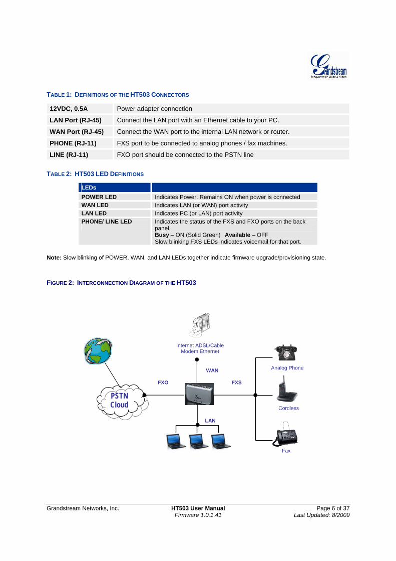
TABLE 1: DEFINITIONS OF THE HT503 CONNECTORS
12VDC, 0.5A Power adapter connection
LAN Port (RJ-45) Connect the LAN port with an Ethernet cable to your PC.
WAN Port (RJ-45) Connect the WAN port to the internal LAN network or router.
PHONE (RJ-11) FXS port to be connected to analog phones / fax machines.
LINE (RJ-11) FXO port should be connected to the PSTN line
TABLE 2: HT503 LED DEFINITIONS
LEDs POWER LED Indicates Power. Remains ON when power is connected WAN LED Indicates LAN (or WAN) port activity LAN LED Indicates PC (or LAN) port activity PHONE/ LINE LED
Indicates the status of the FXS and FXO ports on the back panel. Busy – ON (Solid Green) Available – OFF Slow blinking FXS LEDs indicates voicemail for that port.
Note: Slow blinking of POWER, WAN, and LAN LEDs together indicate firmware upgrade/provisioning state. FIGURE 2: INTERCONNECTION DIAGRAM OF THE HT503
Internet ADSL/Cable Modem Ethernet
Fax
Cordless
Analog Phone WAN
LAN
FXS FXO
PSTN Cloud
Grandstream Networks, Inc. HT503 User Manual Page 7 of 37 Firmware 1.0.1.41 Last Updated: 8/2009
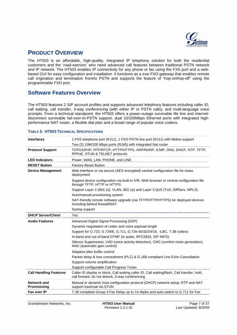
PRODUCT OVERVIEW The HT503 is an affordable, high-quality, integrated IP telephony solution for both the residential customers and the ‘road-warriors’ who need advanced call features between traditional PSTN network and IP network. The HT503 enables IP connectivity for any phone or fax using the FXS port and a web-based GUI for easy configuration and installation. It functions as a true FXO gateway that enables remote call origination and termination from/to PSTN and supports the feature of “hop-on/hop-off” using the programmable FXO port. Software Features Overview The HT503 features 2 SIP account profiles and supports advanced telephony features including caller ID, call waiting, call transfer, 3-way conferencing (with either IP or PSTN calls), and multi-language voice prompts. From a technical standpoint, the HT503 offers a power-outage survivable life line and internet-disconnect survivable fail-over-to-PSTN support, dual 10/100Mbps Ethernet ports with integrated high-performance NAT router, a flexible dial plan and a broad range of popular voice codecs. TABLE 3: HT503 TECHNICAL SPECIFICATIONS
Interfaces 1 FXS telephone port (RJ11), 1 FXO PSTN line port (RJ11) with lifeline support Two (2) 10M/100 Mbps ports (RJ45) with integrated Nat router
Protocol Support TCP/UDP/IP, RTP/RTCP, HTTP/HTTPS, ARP/RARP, ICMP, DNS, DHCP, NTP, TFTP, PPPoE, STUN & TELNET protocols
LED Indicators Power, WAN, LAN, PHONE, and LINE RESET Button Factory Reset Button Device Management Web interface or via secure (AES encrypted) central configuration file for mass
deployment
Support device configuration via built-in IVR, Web browser or central configuration file through TFTP, HTTP or HTTPS
Support Layer 2 (802.1Q, VLAN, 802.1p) and Layer 3 QoS (ToS, DiffServ, MPLS) Auto/manual provisioning system NAT-friendly remote software upgrade (via TFTP/HTTP/HTTPS) for deployed devices
including behind firewall/NAT Syslog support
DHCP Server/Client Yes
Audio Features Advanced Digital Signal Processing (DSP) Dynamic negotiation of codec and voice payload length Support for G.723, G.729/E, G.711, G.726-40/32/24/16, iLBC, T.38 codecs In-band and out-of-band DTMF (in audio, RFC2833, SIP INFO) Silence Suppression, VAD (voice activity detection), CNG (comfort noise generation),
ANG (automatic gain control)
Adaptive jitter buffer control Packet delay & loss concealment (PLC) & G.168 compliant Line Echo Cancellation Support volume amplification Support configurable Call Progress Tones Call Handling Features Caller ID display or block, Call waiting caller ID, Call waiting/flash, Call transfer, hold,
call forward, do not disturb, 3-way conferencing
Network and Provisioning
Manual or dynamic host configuration protocol (DHCP) network setup; RTP and NAT support traversal via STUN
Fax over IP T.38 compliant Group 3 Fax Relay up to 14.4kpbs and auto-switch to G.711 for Fax

Grandstream Networks, Inc. HT503 User Manual Page 8 of 37 Firmware 1.0.1.41 Last Updated: 8/2009
Pass-through (pending), Fax Data pump V.17, V.19, V.27ter, V.29 for T.38 fax relay
Security DIGEST authentication and encryption using MD5 and MD5-sess Physical Design Stylish and compact design; small universal power supply, ideal for travel Hardware Specification The table below lists the hardware specification of HT503. TABLE 4: HT503 HARDWARE SPECIFICATION
LAN interface 1xRJ45 10/100 Mbps Port WAN interface 1xRJ45 10/100 Mbps Port FXS telephone port 1 x FXS (RJ11) FXO telephone port (PSTN Port) 1x PSTN pass-through and life line port LED Power, WAN, LAN, PHONE, and LINE (Green) Universal Switching Power Adaptor
Input: 100–240 VAC, 50-60 Hz Output: 12VDC, 0.5A, UL certified
Dimension 25mm x 115mm x 75mm (when laying flat); 115mm x 25mm x 75mm (standing up)
Weight Approximately 0.6lbs (0.3kg) Temperature Operational: 32° - 104°F or 5° – 45°C
Storage: 10°–130°F Humidity 10% - 90%
(non-condensing) Compliance
Grandstream Networks, Inc. HT503 User Manual Page 9 of 37 Firmware 1.0.1.41 Last Updated: 8/2009
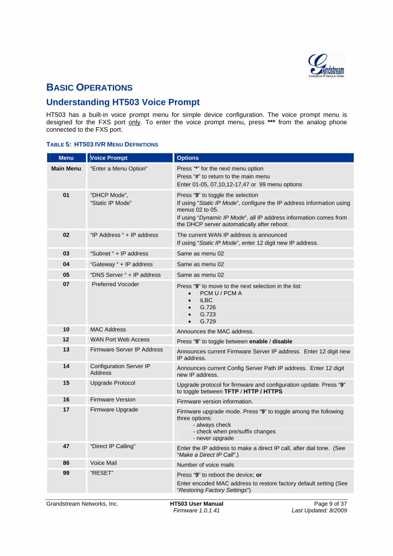
BASIC OPERATIONS Understanding HT503 Voice Prompt HT503 has a built-in voice prompt menu for simple device configuration. The voice prompt menu is designed for the FXS port only. To enter the voice prompt menu, press *** from the analog phone connected to the FXS port. TABLE 5: HT503 IVR MENU DEFINITIONS
Menu Voice Prompt Options
Main Menu “Enter a Menu Option” Press “*” for the next menu option Press “#” to return to the main menu Enter 01-05, 07,10,12-17,47 or 99 menu options
01 “DHCP Mode”, “Static IP Mode”
Press “9” to toggle the selection If using “Static IP Mode”, configure the IP address information using menus 02 to 05. If using “Dynamic IP Mode”, all IP address information comes from the DHCP server automatically after reboot.
02 “IP Address “ + IP address The current WAN IP address is announced If using “Static IP Mode”, enter 12 digit new IP address.
03 “Subnet “ + IP address Same as menu 02
04 “Gateway “ + IP address Same as menu 02
05 “DNS Server “ + IP address Same as menu 02 07 Preferred Vocoder Press “9” to move to the next selection in the list:
• PCM U / PCM A • iLBC • G.726 • G.723 • G.729
10 MAC Address Announces the MAC address. 12 WAN Port Web Access Press “9” to toggle between enable / disable
13 Firmware Server IP Address Announces current Firmware Server IP address. Enter 12 digit new IP address.
14 Configuration Server IP Address
Announces current Config Server Path IP address. Enter 12 digit new IP address.
15 Upgrade Protocol Upgrade protocol for firmware and configuration update. Press “9” to toggle between TFTP / HTTP / HTTPS
16 Firmware Version Firmware version information. 17 Firmware Upgrade Firmware upgrade mode. Press “9” to toggle among the following
three options: - always check - check when pre/suffix changes - never upgrade
47 “Direct IP Calling” Enter the IP address to make a direct IP call, after dial tone. (See “Make a Direct IP Call”.)
86 Voice Mail Number of voice mails 99 “RESET” Press “9” to reboot the device; or
Enter encoded MAC address to restore factory default setting (See “Restoring Factory Settings”)
Grandstream Networks, Inc. HT503 User Manual Page 10 of 37 Firmware 1.0.1.41 Last Updated: 8/2009
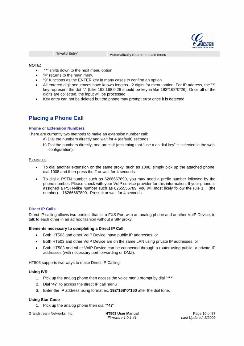
“Invalid Entry” Automatically returns to main menu NOTE:
• “*” shifts down to the next menu option • “#” returns to the main menu • “9” functions as the ENTER key in many cases to confirm an option • All entered digit sequences have known lengths - 2 digits for menu option. For IP address, the "*"
key represent the dot "." (Like 192.168.0.26 should be key in like 192*168*0*26). Once all of the digits are collected, the input will be processed.
• Key entry can not be deleted but the phone may prompt error once it is detected Placing a Phone Call
Phone or Extension Numbers There are currently two methods to make an extension number call:
a) Dial the numbers directly and wait for 4 (default) seconds. b) Dial the numbers directly, and press # (assuming that “use # as dial key” is selected in the web
configuration).
EXAMPLES:
• To dial another extension on the same proxy, such as 1008, simply pick up the attached phone, dial 1008 and then press the # or wait for 4 seconds.
• To dial a PSTN number such as 6266667890, you may need a prefix number followed by the phone number. Please check with your VoIP service provider for this information. If your phone is assigned a PSTN-like number such as 6265556789, you will most likely follow the rule 1 + (the number) – 16266667890. Press # or wait for 4 seconds.
Direct IP Calls Direct IP calling allows two parties, that is, a FXS Port with an analog phone and another VoIP Device, to talk to each other in an ad hoc fashion without a SIP proxy. Elements necessary to completing a Direct IP Call:
• Both HT503 and other VoIP Device, have public IP addresses, or • Both HT503 and other VoIP Device are on the same LAN using private IP addresses, or • Both HT503 and other VoIP Device can be connected through a router using public or private IP
addresses (with necessary port forwarding or DMZ). HT503 supports two ways to make Direct IP Calling: Using IVR
1. Pick up the analog phone then access the voice menu prompt by dial “***” 2. Dial “47” to access the direct IP call menu 3. Enter the IP address using format ex. 192*168*0*160 after the dial tone.
Using Star Code
1. Pick up the analog phone then dial “*47”
Grandstream Networks, Inc. HT503 User Manual Page 11 of 37 Firmware 1.0.1.41 Last Updated: 8/2009
2. Enter the target IP address using same format as above. Note: NO dial tone will be played between step 1 and 2.
Destination ports can be specified by using “*” (encoding for “:”) followed by the port number. Examples:
a) If the target IP address is 192.168.0.160, the dialing convention is *47 or Voice Prompt with option 47, then 192*168*0*160. followed by pressing the “#” key if it is configured as a send key or wait 4 seconds. In this case, the default destination port 5060 is used if no port is specified.
b) If the target IP address/port is 192.168.1.20:5062, then the dialing convention would be: *47 or Voice Prompt with option 47, then 192*168*0*160*5062 followed by pressing the “#” key if it is configured as a send key or wait for 4 seconds.
NOTE: When completing direct IP call, the “Use Random Port” should set to “NO”. You can not make direct IP calls between FXS1 to FXS2 since they are using same IP. Call Hold This function is applicable on the FXS port for VoIP calls only. While in conversation, pressing the “flash” button on the connected phone (if the phone has that button) places the remote end on hold. Pressing the “flash” button again releases the previously held party and the conversation can resume. If no “flash” button is available, then on-off hook quickly (hook flash) will do the same thing. You may lose the call if ‘hook flash’ is not quick enough. Call Waiting This function is applicable on FXS port for VoIP calls only. If the call waiting feature is enabled, the user will hear a special stutter tone if there is another call on the line. Press the flash button to place the current party on hold and switch to the other call. Pressing the flash button toggles between two active calls. The HT503 also provides CWCID (call waiting caller ID) information which includes caller ID information in addition to the special stutter tone. The analog phone must support this feature for it to work on the HT503. Both call waiting functions (call waiting and CWCID) are activated and deactivated from the configuration pages menu.
Call Transfer The HT503 supports both blind transfer and attended transfer.
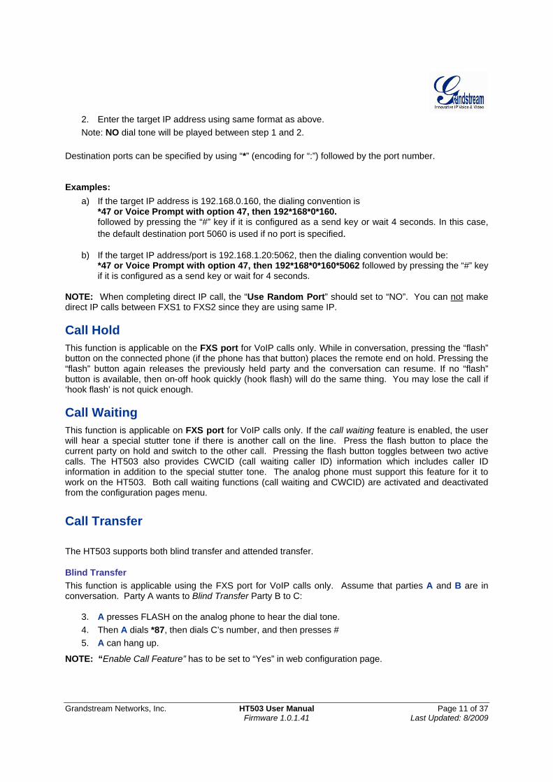
Blind Transfer This function is applicable using the FXS port for VoIP calls only. Assume that parties A and B are in conversation. Party A wants to Blind Transfer Party B to C:
3. A presses FLASH on the analog phone to hear the dial tone. 4. Then A dials *87, then dials C’s number, and then presses # 5. A can hang up.
NOTE: “Enable Call Feature” has to be set to “Yes” in web configuration page.
Grandstream Networks, Inc. HT503 User Manual Page 12 of 37 Firmware 1.0.1.41 Last Updated: 8/2009
Three situations can follow the transfer: 1. A quick confirmation tone (temporarily using the call waiting indication tone) followed by a
dialtone. This indicates the transfer was successful (transferee has received a 200 OK from transfer target). A can either hang up or make another call.
2. A quick busy tone followed by a restored call (on supported platforms only). This means the transferee has received a 4xx response for the INVITE and we will try to recover the call. The busy tone indicates the transfer has failed.
3. Busy tone keeps playing. This means we have failed to receive the second NOTIFY from the transferee and the call has timed out. Note: this does not indicate the transfer has been successful, nor does it indicate the transfer has failed. When transferee is a client that does not support the second NOTIFY (such as our own earlier firmware), this situation occurs. In bad network scenarios, this could also happen, although the transfer may have been completed successfully.
Attended Transfer This function is applicable on the FXS port for VoIP calls only. Assume that parties A and B are in conversation. Party A wants to Attend Transfer Party B to C:
1. A presses FLASH on the analog phone to get a dial tone; 2. A then dial C’s number followed by #. 3. If C answers the call, A and C are in conversation. Then A can hang up to complete transfer. 4. If C does not answer the call, A can press “flash” back to talk to B.
NOTE: When Attended Transfer fails and A hangs up, the HT503 will ring user A back again to remind A that party B is still on the call. Party A can pick up the phone to resume a conversation with party B. 3-way Conferencing The HT503 supports Bellcore Style 3-way conferencing. Assume that parties A and B are in conversation. Party A (using the HT503) wants to bring C into a 3-way conference:
1. A presses FLASH (on the analog phone, or Hook Flash for old model phones) to get a dial tone.
2. A dials C’s number then # (or wait for 4 seconds). 3. If C answers the call, then A presses FLASH to bring B, C in the conference. 4. If C does not answer the call, A can press FLASH back to talk to B. 5. If A presses FLASH during the conference, C will be dropped out. 6. If A hangs up, the conference will be terminated for all three parties when configuration
“Transfer on Conference Hangup” is set to “No”. If the configuration is set to “Yes”, A will transfer B to C so that B and C can continue the conversation.
PSTN Pass Through HT503 supports PSTN pass through using the FXS port. The user can place and receive PSTN calls using analog phone connected to FXS port.
Grandstream Networks, Inc. HT503 User Manual Page 13 of 37 Firmware 1.0.1.41 Last Updated: 8/2009
• To receive PSTN calls, pick up the phone when it rings; • To complete a PSTN call, press the PSTN access code (*00 is default, or any number configured
in the web configuration) to switch to the PSTN line, listen for a dial tone, then dial the number. • If the 503 loses power or lost registration with SIP server, device will switch to mode when PSTN
line will be transparently connected directly to phone connected to FXS port. It will function as a jack, enabling a direct connection to the PSTN Line.
VoIP-to-PSTN Calls This function is available using the FXO port. The FXO port functions as a bridge between the Internet and PSTN. The user can remotely use a PSTN line to initiate a call. TO MAKE A VOIP-TO-PSTN CALL:
1. Dial the FXO SIP account phone number to establish the VoIP session. The caller will hear the ring back tone once. Then the caller hears either a special continuous tone or a dial tone. The special continuous tone is played if the pin code is configured, otherwise, the caller will hear a dial tone.
2. Enter the PIN code (if configured under the BASIC configuration page). The caller will hear a dial tone and be connected to the PSTN line if the PIN code is valid. If the PIN code is invalid, the continuous tone is played to prompt caller to enter the PIN code again. The user may try up to 3 times to enter a correct PIN code. After three (3) tries, the HT503 hangs up.
3. After the caller hears a dial tone from PSTN line, the caller can place the next call. 4. The user can hit the # key to identify the end of the pin code or wait 4 seconds for a new dial tone
and then dialing the PSTN number. Note:
• Users can choose whether or not to apply password protection for VoIP-to-PSTN calls. A PIN (Pin for PSTN calls) consists of up to 8 numeric digits and can be configured using the BASIC SETTINGS of the web configuration page. By default, there is no password protection. (I.e. there is no authentication required for callers on the use of PSTN line through HT503).
• When a PIN is configured for VOIP-to-PSTN call flow, the VoIP device that calls into the HT503 FXO account needs to configure RFC2833 or SIP Info for DTMF digit transmission.
• The special continuous tone is the prompt to enter a valid PIN code. If a caller doesn’t enter a valid PIN, the HT503 times out after 10 seconds. Users may press the “#” key to indicate the end of an input or wait 4 seconds.
• On the web configuration page, if the “Forward to PSTN” is configured, the second stage dialing format is eliminated, so after dialing into the FXO SIP account number, the PSTN number will be called automatically
PSTN-to-VoIP Calls This function is available using the FXO port. The FXO port functions as a bridge between the Internet and PSTN and enables calls to be passed from the PSTN network to VoIP. The user can make VoIP calls remotely by dialing into the FXO line port on HT503. To Make a PSTN-to-VoIP Call:
1. Make an incoming call to the PSTN line on FXO port. The phone will ring for 4 times by default (this setting is configurable on the FXO port configuration page).
Grandstream Networks, Inc. HT503 User Manual Page 14 of 37 Firmware 1.0.1.41 Last Updated: 8/2009
2. If no one answers the call after 4 rings (default configuration), then the caller hears either a special continuous tone (prompting a PIN number) or a dial tone.
3. Enter a valid PIN (if configured under the BASIC configuration page). The caller will hear dial tone and be bridged to VoIP. If an incorrect PIN is input, the continuous tone prompts caller to enter a valid PIN. The caller may try 3 times to enter a valid PIN, if it is invalid the HT503 will hang up.
4. The caller can dial a VoIP number followed by # (or wait for 4 seconds); the VoIP call will be initiated from the SIP account configured on the FXO port.
NOTE:
• Users can choose whether or not to apply password protection for VoIP-to-PSTN calls. A PIN (Pin for PSTN calls) consists of up to 8 numeric digits and can be configured using the BASIC SETTINGS of the web configuration page. By default, there is no password protection. (I.e. there is no authentication required for callers on the use of PSTN line through HT503).
• When a PIN is configured for VOIP-to-PSTN call flow, the VoIP device that calls into the HT503 FXO account needs to configure RFC2833 or SIP Info for DTMF digit transmission.
• The special continuous tone is the prompt to enter a valid PIN code. If a caller doesn’t enter a valid PIN, the HT503 times out after 10 seconds. Users may press the “#” key to indicate the end of an input or wait 4 seconds.
• On the web configuration page, if the “Forward to VoIP” is configured, the second stage dialing format is eliminated, so after dialing into the FXO SIP account number, the PSTN number will be called automatically
Route Calls to PSTN The FXO port enables access to the PSTN network. By default, the HT503 is in VoIP mode at off-hook. If “Route Call to PSTN” is configured, certain calls will be initiated from the FXO PSTN line port. This call feature is especially useful for emergency calls or local telephone calls. To use this feature, users need to specify a special rule using the dial plan parameter located under FXS Port configuration page. If the dialed digits match the specified prefix, outbound calls will be initiated from the PSTN line. Note: The route to PSTN feature is only applicable to a phone connected to the FXS Port. The configuration is done using the “dial plan” feature under the FXS tab. An example of the configuration is {L: 911x+}. This shows that only calls that start with 911 are immediately forwarded to the PSTN line. All other numbers will not be routed to the PSTN. An normal # would be: {L: 617x+|x+} or {x+| L: 617x+} For example, if “Route Call to PSTN” is configured as {L: 626x+}, all outgoing calls starting with 626 will be initiated from the PSTN line. Forward Calls to PSTN Any VOIP call may be forwarded to a specified PSTN number. FXO port should be registered with some preconfigured number (for example 1111). Any VoIP extension can dial this FXO account number and will be automatically forwarded to preconfigured PSTN extension. For example, if the end-user has configured a cell phone number in the field “Forward to PSTN” under BASIC SETTINGS configuration page, all calls will be forwarded to the cell phone number after 4 rings.
Grandstream Networks, Inc. HT503 User Manual Page 15 of 37 Firmware 1.0.1.41 Last Updated: 8/2009
Forward Calls to VoIP By default, each incoming PSTN call is received over the FXS port. The end-user may forward such a call to any preconfigured VoIP extension, in case the call is not answered in a certain number of rings. The Default value of the parameter “Number of Rings” is 4. This parameter located under “FXO Port” configuration page. If during 4 rings, the incoming from the PSTN call is not answered, the call will be forwarded to another VoIP number previously configured in the field:”Forward to VoIP”. This parameter can also be found under BASIC SETTINGS configuration page. One Stage Dialing This feature is applicable for VoIP to PSTN calls. Any VoIP extension may dial directly to a local PSTN number if the one-stage dialing feature is activated. This feature is configured under the FXO Configuration page and requires SIP Server configuration and support. The special dial plan feature must be activated in the SIP Server. An outbound call will be sent directly to the assigned FXO port account, where there the HT503 will initiate a call to the local CO. The RequestURI header in the INVITE message contains the phone number used to initiate the call to the local CO. Fax Support HT503 supports FAX in two modes: 1) T.38 (Fax over IP) and 2) fax pass through. T.38 is the preferred method because it is more reliable and works well in most network conditions. If the service provider supports T.38, please use this method by selecting Fax mode to be T.38 (default). If the service provider does not support T.38, pass-through mode may be used. To send or receive faxes in fax pass through mode, users must select all the Preferred Codecs to be PCMU/PCMA (G.711-µ/a).
Grandstream Networks, Inc. HT503 User Manual Page 16 of 37 Firmware 1.0.1.41 Last Updated: 8/2009
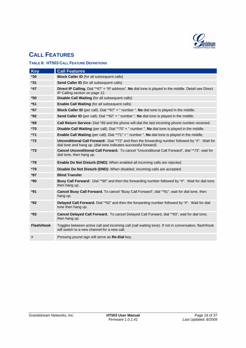
CALL FEATURES TABLE 6: HT503 CALL FEATURE DEFINITIONS
Key Call Features *30 Block Caller ID (for all subsequent calls)
*31 Send Caller ID (for all subsequent calls)
*47 Direct IP Calling. Dial “*47” + “IP address”. No dial tone is played in the middle. Detail see Direct IP Calling section on page 12.
*50 Disable Call Waiting (for all subsequent calls)
*51 Enable Call Waiting (for all subsequent calls)
*67 Block Caller ID (per call). Dial “*67” + ” number ”. No dial tone is played in the middle.
*82 Send Caller ID (per call). Dial “*82” + ” number ”. No dial tone is played in the middle.
*69 Call Return Service: Dial *69 and the phone will dial the last incoming phone number received. *70 Disable Call Waiting (per call). Dial “*70” + ” number ”. No dial tone is played in the middle.
*71 Enable Call Waiting (per call). Dial “*71” + ” number ”. No dial tone is played in the middle.
*72 Unconditional Call Forward: Dial “*72” and then the forwarding number followed by “#”. Wait for dial tone and hang up. (dial tone indicates successful forward)
*73 Cancel Unconditional Call Forward. To cancel “Unconditional Call Forward”, dial “*73”, wait for dial tone, then hang up.
*78 Enable Do Not Disturb (DND): When enabled all incoming calls are rejected.
*79 Disable Do Not Disturb (DND): When disabled, incoming calls are accepted. *87 Blind Transfer *90 Busy Call Forward: Dial “*90” and then the forwarding number followed by “#”. Wait for dial tone
then hang up.
*91 Cancel Busy Call Forward. To cancel “Busy Call Forward”, dial “*91”, wait for dial tone, then hang up.
*92 Delayed Call Forward. Dial “*92” and then the forwarding number followed by “#”. Wait for dial tone then hang up.
*93 Cancel Delayed Call Forward. To cancel Delayed Call Forward, dial “*93”, wait for dial tone, then hang up.
Flash/Hook Toggles between active call and incoming call (call waiting tone). If not in conversation, flash/hook will switch to a new channel for a new call.
# Pressing pound sign will serve as Re-Dial key.
Grandstream Networks, Inc. HT503 User Manual Page 17 of 37 Firmware 1.0.1.41 Last Updated: 8/2009
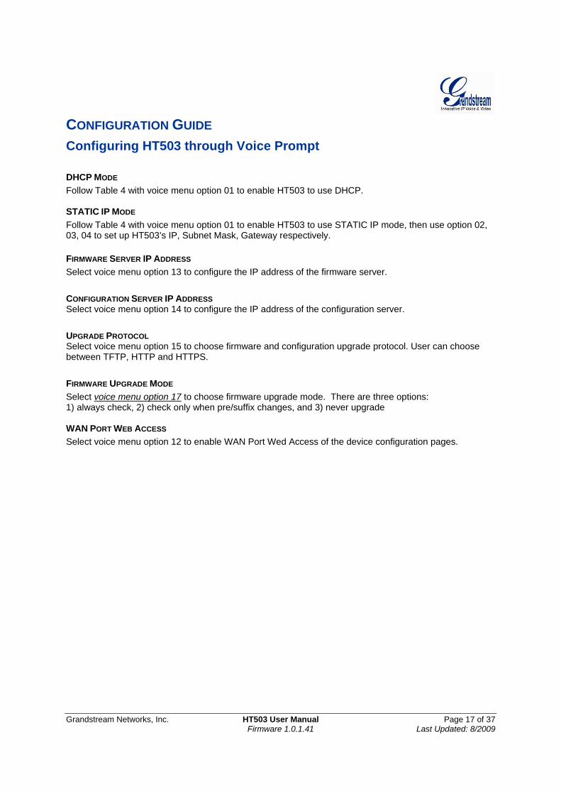
CONFIGURATION GUIDE Configuring HT503 through Voice Prompt DHCP MODE Follow Table 4 with voice menu option 01 to enable HT503 to use DHCP. STATIC IP MODE Follow Table 4 with voice menu option 01 to enable HT503 to use STATIC IP mode, then use option 02, 03, 04 to set up HT503’s IP, Subnet Mask, Gateway respectively. FIRMWARE SERVER IP ADDRESS Select voice menu option 13 to configure the IP address of the firmware server.
CONFIGURATION SERVER IP ADDRESS Select voice menu option 14 to configure the IP address of the configuration server.
UPGRADE PROTOCOL Select voice menu option 15 to choose firmware and configuration upgrade protocol. User can choose between TFTP, HTTP and HTTPS.
FIRMWARE UPGRADE MODE Select voice menu option 17 to choose firmware upgrade mode. There are three options: 1) always check, 2) check only when pre/suffix changes, and 3) never upgrade WAN PORT WEB ACCESS Select voice menu option 12 to enable WAN Port Wed Access of the device configuration pages.
Grandstream Networks, Inc. HT503 User Manual Page 18 of 37 Firmware 1.0.1.41 Last Updated: 8/2009
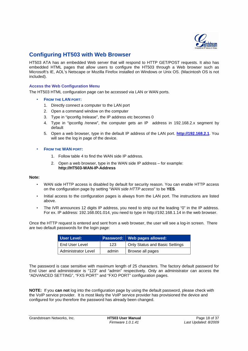
Configuring HT503 with Web Browser HT503 ATA has an embedded Web server that will respond to HTTP GET/POST requests. It also has embedded HTML pages that allow users to configure the HT503 through a Web browser such as Microsoft’s IE, AOL’s Netscape or Mozilla Firefox installed on Windows or Unix OS. (Macintosh OS is not included).
Access the Web Configuration Menu The HT503 HTML configuration page can be accessed via LAN or WAN ports.
• FROM THE LAN PORT: 1. Directly connect a computer to the LAN port 2. Open a command window on the computer 3. Type in “ipconfig /release”, the IP address etc becomes 0 4. Type in “ipconfig /renew”, the computer gets an IP address in 192.168.2.x segment by
default 5. Open a web browser, type in the default IP address of the LAN port. http://192.168.2.1. You
will see the log in page of the device.
• FROM THE WAN PORT:
1. Follow table 4 to find the WAN side IP address.
2. Open a web browser, type in the WAN side IP address – for example: http://HT503-WAN-IP-Address
Note:
• WAN side HTTP access is disabled by default for security reason. You can enable HTTP access on the configuration page by setting “WAN side HTTP access” to be YES.
• Initial access to the configuration pages is always from the LAN port. The instructions are listed above.
• The IVR announces 12 digits IP address, you need to strip out the leading “0” in the IP address. For ex. IP address: 192.168.001.014, you need to type in http://192.168.1.14 in the web browser.
Once the HTTP request is entered and sent from a web browser, the user will see a log-in screen. There are two default passwords for the login page:
User Level: Password: Web pages allowed: End User Level 123 Only Status and Basic Settings Administrator Level admin Browse all pages
The password is case sensitive with maximum length of 25 characters. The factory default password for End User and administrator is “123” and “admin” respectively. Only an administrator can access the “ADVANCED SETTING”, “FXS PORT” and “FXO PORT” configuration pages. NOTE: If you can not log into the configuration page by using the default password, please check with the VoIP service provider. It is most likely the VoIP service provider has provisioned the device and configured for you therefore the password has already been changed.
Grandstream Networks, Inc. HT503 User Manual Page 19 of 37 Firmware 1.0.1.41 Last Updated: 8/2009
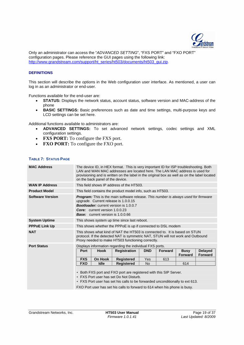
Only an administrator can access the “ADVANCED SETTING”, “FXS PORT” and “FXO PORT” configuration pages. Please reference the GUI pages using the following link: http://www.grandstream.com/support/ht_series/ht503/documents/ht503_gui.zip. DEFINITIONS This section will describe the options in the Web configuration user interface. As mentioned, a user can log in as an administrator or end-user. Functions available for the end-user are:
• STATUS: Displays the network status, account status, software version and MAC-address of the phone
• BASIC SETTINGS: Basic preferences such as date and time settings, multi-purpose keys and LCD settings can be set here.
Additional functions available to administrators are:
• ADVANCED SETTINGS: To set advanced network settings, codec settings and XML configuration settings.
• FXS PORT: To configure the FXS port. • FXO PORT: To configure the FXO port.
TABLE 7: STATUS PAGE
MAC Address The device ID, in HEX format. This is very important ID for ISP troubleshooting. Both LAN and WAN MAC addresses are located here. The LAN MAC address is used for provisioning and is written on the label in the original box as well as on the label located on the back panel of the device.
WAN IP Address This field shows IP address of the HT503. Product Model This field contains the product model info, such as HT503. Software Version Program: This is the main software release. This number is always used for firmware
upgrade. Current release is 1.0.0.15 Bootloader: current version is 1.0.0.7 Core: current version 1.0.0.23 Base: current version is 1.0.0.66
System Uptime This shows system up time since last reboot. PPPoE Link Up This shows whether the PPPoE is up if connected to DSL modem NAT This shows what kind of NAT the HT503 is connected to. It is based on STUN
protocol. If the detected NAT is symmetric NAT, STUN will not work and Outbound Proxy needed to make HT503 functioning correctly.
Port Status Displays information regarding the individual FXS ports. Port Hook Registration DND Forward Busy
Forward Delayed Forward
FXS On Hook Registered Yes 613 FXO Idle Registered No 614
• Both FXS port and FXO port are registered with this SIP Server. • FXS Port user has set Do Not Disturb. • FXS Port user has set his calls to be forwarded unconditionally to ext 613. FXO Port user has set his calls to forward to 614 when his phone is busy.
Grandstream Networks, Inc. HT503 User Manual Page 20 of 37 Firmware 1.0.1.41 Last Updated: 8/2009
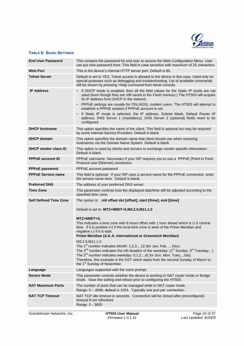
TABLE 8: BASIC SETTINGS
End User Password This contains the password for end user to access the Web Configuration Menu. User can put new password here. This field is case sensitive with maximum of 25 characters
Web Port This is the device’s internal HTTP server port. Default is 80. Telnet Server Default is set to YES. Telnet access is allowed to the device in this case. Used only for
special purposes such as debugging and troubleshooting. List of available commands will be shown by pressing >help command from telnet console.
IP Address • If DHCP mode is enabled, then all the field values for the Static IP mode are not used (even though they are still saved in the Flash memory.) The HT503 will acquire its IP address from DHCP in the network.
• PPPoE settings are usually for DSL/ADSL modem users. The HT503 will attempt to establish a PPPoE session if PPPoE account is set.
• If Static IP mode is selected, the IP address, Subnet Mask, Default Router IP address, DNS Server 1 (mandatory), DNS Server 2 (optional) fields need to be configured.
DHCP hostname This option specifies the name of the client. This field is optional but may be required by some Internet Service Providers. Default is blank.
DHCP domain This option specifies the domain name that client should use when resolving hostnames via the Domain Name System. Default is blank.
DHCP vendor class ID This option is used by clients and servers to exchange vendor-specific information. Default is blank.
PPPoE account ID PPPoE username. Necessary if your ISP requires you to use a PPPoE (Point to Point Protocol over Ethernet) connection
PPPoE password PPPoE account password PPPoE Service name This field is optional. If your ISP uses a service name for the PPPoE connection, enter
the service name here. Default is blank. Preferred DNS The address of your preferred DNS server. Time Zone This parameter controls how the displayed date/time will be adjusted according to the
specified time zone. Self Defined Time Zone The syntax is: std offset dst [offset], start [/time], end [/time]
Default is set to: MTZ+6MDT+5,M3.2.0,M11.1.0 MTZ+6MDT+5, This indicates a time zone with 6 hours offset with 1 hour ahead which is U.S central time. If it is positive (+) if the local time zone is west of the Prime Meridian and negative (-) if it is east. Prime Meridian (A.K.A: International or Greenwich Meridian) M3.2.0,M11.1.0 The 1st number indicates Month: 1,2,3.., 12 (for Jan, Feb, .., Dec) The 2nd number indicates the nth iteration of the weekday: (1st Sunday, 3rd Tuesday…) The 3rd number indicates weekday: 0,1,2,..,6( for Sun, Mon, Tues,..,Sat) Therefore, this example is the DST which starts from the second Sunday of March to the 1st Sunday of November.
Language Languages supported with the voice prompt. Device Mode This parameter controls whether the device is working in NAT router mode or Bridge
mode. Save the setting and reboot prior to configuring the HT503. NAT Maximum Ports The number of ports that can be managed while in NAT router mode.
Range: 0 – 4096, default is 1024. Typically one port per connection. NAT TCP Timeout NAT TCP idle timeout in seconds. Connection will be closed after preconfigured,
timeout if not refreshed. Range: 0 - 3600
Grandstream Networks, Inc. HT503 User Manual Page 21 of 37 Firmware 1.0.1.41 Last Updated: 8/2009
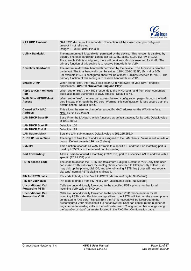
NAT UDP Timeout NAT TCP idle timeout in seconds. Connection will be closed after preconfigured, timeout if not refreshed. Range: 0 – 3600, default is 300
Uplink Bandwidth The maximum uplink bandwidth permitted by the device. This function is disabled by default. The total bandwidth can be set as: 128K, 256K, 512K, 1M, 4M or 10M. For example if 64 is configured, there will be at least 64kbps reserved for VoIP. The primary function of this setting is to reserve bandwidth for VoIP.
Downlink Bandwidth The maximum downlink bandwidth permitted by the device. This function is disabled by default. The total bandwidth can be set as: 128K, 256K, 512K, 1M, 4M or 10M. For example if 128 is configured, there will be at least 128kbps reserved for VoIP. The primary function of this setting is to reserve bandwidth for VoIP.
Enable UPnP When set to “Yes”, the HT503 acts as an UPnP gateway for your UPnP enabled applications. UPnP = “Universal Plug and Play”
Reply to ICMP on WAN Port
When set to “Yes”, the HT503 responds to the PING command from other computers, but is also made vulnerable to DOS attacks. Default is No.
WAN Side HTTP/Telnet Access
When set to “Yes”, the user can access the web configuration pages through the WAN port, instead of through the PC port. Warning: this configuration is less secure than the default option. Default is No.
Cloned WAN MAC Address
This allows the user to change/set a specific MAC address on the WAN interface. Note: Set in Hex format
LAN DHCP Base IP
Base IP for the LAN port, which functions as default gateway for its LAN. Default value is 192.168.2.1
LAN DHCP Start IP Default is 100 LAN DHCP End IP Default is 199 LAN Subnet Mask Sets the LAN subnet mask. Default value is 255.255.255.0 DHCP IP Lease Time The length of time the IP address is assigned to the LAN clients. Value is set in units of
hours. Default value is 120 hrs (5 days). DMZ IP:
This function forwards all WAN IP traffic to a specific IP address if no matching port is used by HT503 or in the defined port forwarding.
Port Forwarding: Allows users to forward a matching (TCP/UDP) port to a specific LAN IP address with a specific (TCP/UDP) port.
PSTN access code The code to access the PSTN line (Maximum 5 digits). Default is “*00”. Any time user can make PSTN calls from the analog phone connected to FXS port. By default, user may pick up the phone, dial *00, and after obtaining PSTN line ( user will hear regular dial tone) normal PSTN dialing is allowed.
PIN for PSTN calls PIN code to bridge from VoIP to PSTN (Maximum 8 digits, No Default) PIN for VoIP calls PIN code to bridge from PSTN to VoIP (Maximum 8 digits, No Default) Unconditional Call Forward to PSTN
Calls are unconditionally forwarded to the specified PSTN phone number for all incoming VoIP calls on FXO port.
Unconditional Call Forward to VoIP
Calls are unconditionally forwarded to the specified VoIP phone number for all incoming PSTN calls. Each incoming call from the PSTN will first ring the analog phone connected to FXS port. This call from the PSTN network will be forwarded to the preconfigured VoIP extension if it is not answered. User can configure the number of rings before forwarding calls to the VoIP extension. Configure number of rings using the “number of rings” parameter located in the FXO Port Configuration page.
Grandstream Networks, Inc. HT503 User Manual Page 22 of 37 Firmware 1.0.1.41 Last Updated: 8/2009
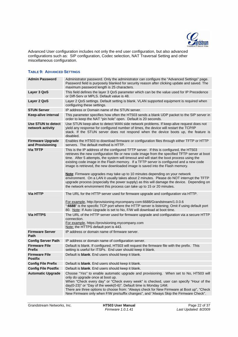
Advanced User configuration includes not only the end user configuration, but also advanced configurations such as: SIP configuration, Codec selection, NAT Traversal Setting and other miscellaneous configuration.
TABLE 9: ADVANCED SETTINGS
Admin Password Administrator password. Only the administrator can configure the “Advanced Settings” page. Password field is purposely blanked for security reason after clicking update and saved. The maximum password length is 25 characters.
Layer 3 QoS This field defines the layer 3 QoS parameter which can be the value used for IP Precedence or Diff-Serv or MPLS. Default value is 48.
Layer 2 QoS Layer 2 QoS settings. Default setting is blank. VLAN supported equipment is required when configuring these settings.
STUN Server IP address or Domain name of the STUN server. Keep-alive interval This parameter specifies how often the HT503 sends a blank UDP packet to the SIP server in
order to keep the NAT “pin hole” open. Default is 20 seconds. Use STUN to detect network activity
Use STUN keep-alive to detect WAN side network problems. If keep-alive request does not yield any response for configured number of times, the device will restart the TCP/IP stack. If the STUN server does not respond when the device boots up, the feature is disabled.
Firmware Upgrade and Provisioning
Enables the HT503 to download firmware or configuration files through either TFTP or HTTP servers. The default method is HTTP.
Via TFTP This is the IP address of the configured TFTP server. If this is configured, the HT503 retrieves the new configuration file or new code image from the specified TFTP server at boot time. After 5 attempts, the system will timeout and will start the boot process using the existing code image in the Flash memory. If a TFTP server is configured and a new code image is retrieved, the new downloaded image is saved into the Flash memory. Note: Firmware upgrades may take up to 10 minutes depending on your network environment. On a LAN it usually takes about 2 minutes. Please do NOT interrupt the TFTP upgrade process (especially the power supply) as this will damage the device. Depending on the network environment this process can take up to 15 or 20 minutes.
Via HTTP The URL for the HTTP server used for firmware upgrade and configuration via HTTP. For example, http://provisioning.mycompany.com:6688/Grandstream/1.0.0.6 “:6688” is the specific TCP port where the HTTP server is listening; Omit if using default port 80. Note: If Auto Upgrade is set to No, F/W will download at boot time.
Via HTTPS The URL of the HTTP server used for firmware upgrade and configuration via a secure HTTP connection. For example, https://provisioning.mycompany.com Note: the HTTPS default port is 443.
Firmware Server Path
IP address or domain name of firmware server.
Config Server Path IP address or domain name of configuration server. Firmware File Prefix
Default is blank. If configured, HT503 will request the firmware file with the prefix. This setting is useful for ITSPs. End user should keep it blank.
Firmware File Postfix
Default is blank. End users should keep it blank.
Config File Prefix Default is blank. End users should keep it blank. Config File Postfix Default is blank. End users should keep it blank. Automatic Upgrade Choose “Yes” to enable automatic upgrade and provisioning. When set to No, HT503 will
only do upgrade once at boot up. When “Check every day” or “Check every week” is checked, user can specify “Hour of the day(0-23)” or “Day of the week(0-6)”. Default time is Monday 1AM. There are three options to choose from: “Always check for New Firmware at Boot up”, “Check New Firmware only when F/W pre/suffix changes”, and “Always Skip the Firmware Check”.
Grandstream Networks, Inc. HT503 User Manual Page 23 of 37 Firmware 1.0.1.41 Last Updated: 8/2009
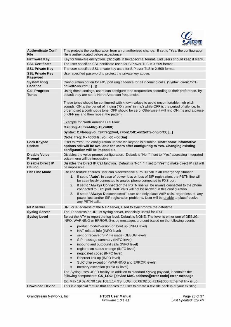
Authenticate Conf File
This protects the configuration from an unauthorized change. If set to “Yes, the configuration file is authenticated before acceptance.
Firmware Key Key for firmware encryption. (32 digits in hexadecimal format. End users should keep it blank. SSL Certificate The user specified SSL certificate used for SIP over TLS in X.509 format. SSL Private Key The user specified SSL private key used for SIP over TLS in X.509 format. SSL Private Key Password
User specified password to protect the private key above.
System Ring Cadence
Configuration option for FXS port ring cadence for all incoming calls. (Syntax: c=on1/off1-on2/off2-on3/off3; [...])
Call Progress Tones
Using these settings, users can configure tone frequencies according to their preference. By default they are set to North American frequencies. These tones should be configured with known values to avoid uncomfortable high pitch sounds. ON is the period of ringing (“On time” in ‘ms’) while OFF is the period of silence. In order to set a continuous tone, OFF should be zero. Otherwise it will ring ON ms and a pause of OFF ms and then repeat the pattern. Example for North America Dial Plan: f1=350@-13,f2=440@-13,c=0/0; Syntax: f1=freq@vol, f2=freq@vol, c=on1/off1-on2/off2-on3/off3; [...] (Note: freq: 0 - 4000Hz; vol: -30 - 0dBm)
Lock Keypad Update
If set to “Yes”, the configuration update via keypad is disabled. Note: some informative options still will be available for users after configuring to Yes. Changing existing configuration will be impossible.
Disable Voice Prompt
Disables the voice prompt configuration. Default is “No. ” If set to “Yes” accessing integrated voice menu will be impossible.
Disable Direct IP Calling
Disables the Direct IP Call function. Default is “No.” ” If set to “Yes” to make direct IP call will be impossible.
Life Line Mode Life line feature ensures user can place/receive a PSTN call in an emergency situation. 1. If set to “Auto”, in case of power loss or loss of SIP registration, the PSTN line will
be seamlessly connected to analog phone connected to FXS port. 2. If set to “Always Connected” the PSTN line will be always connected to the phone
connected to FXS port. VoIP calls will not be allowed in this configuration. 3. If set to “Always Disconnected”, user can only place VoIP calls, regardless of any
power loss and/or SIP registration problems. User will be unable to place/receive any PSTN calls.
NTP server URL or IP address of the NTP server, Used to synchronize the date/time. Syslog Server The IP address or URL of syslog server, especially useful for ITSP Syslog Level Select the ATA to report the log level. Default is NONE. The level is either one of DEBUG,
INFO, WARNING or ERROR. Syslog messages are sent based on the following events: • product model/version on boot up (INFO level) • NAT related info (INFO level) • sent or received SIP message (DEBUG level) • SIP message summary (INFO level) • inbound and outbound calls (INFO level) • registration status change (INFO level) • negotiated codec (INFO level) • Ethernet link up (INFO level) • SLIC chip exception (WARNING and ERROR levels) • memory exception (ERROR level)
The Syslog uses USER facility. In addition to standard Syslog payload, it contains the following components: GS_LOG: [device MAC address][error code] error message Ex. May 19 02:40:38 192.168.1.14 GS_LOG: [00:0b:82:00:a1:be][000] Ethernet link is up
Download Device This is a special feature that enables the user to create a text file backup of your existing
Grandstream Networks, Inc. HT503 User Manual Page 24 of 37 Firmware 1.0.1.41 Last Updated: 8/2009
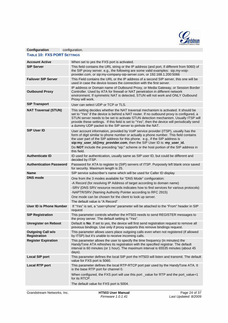
Configuration configuration. TABLE 10: FXS PORT SETTINGS
Account Active When set to yes the FXS port is activated. SIP Server This field contains the URL string or the IP address (and port, if different from 5060) of
the SIP proxy server. e.g., the following are some valid examples: sip.my-voip-provider.com, or sip:my-company-sip-server.com, or 192.168.1.200:5066
Failover SIP Server This Field contains the URL or the IP address of a second SIP server, this one will be used in case the device looses the connection with the first server.
Outbound Proxy
IP address or Domain name of Outbound Proxy, or Media Gateway, or Session Border Controller. Used by ATA for firewall or NAT penetration in different network environment. If symmetric NAT is detected, STUN will not work and ONLY Outbound Proxy will work.
SIP Transport User can select UDP or TCP or TLS. NAT Traversal (STUN) This setting decides whether the NAT traversal mechanism is activated. It should be
set to “Yes” if the device is behind a NAT router. If no outbound proxy is configured, a STUN server needs to be set to activate STUN detection mechanism. Usually ITSP will provide these settings. If this field is set to “Yes”, then the device will periodically send a dummy UDP packet to the SIP server to pinhole the NAT.
SIP User ID User account information, provided by VoIP service provider (ITSP), usually has the form of digit similar to phone number or actually a phone number. This field contains the user part of the SIP address for this phone. e.g., if the SIP address is sip:my_user_id@my_provider.com, then the SIP User ID is: my_user_id. Do NOT include the preceding “sip:” scheme or the host portion of the SIP address in this field.
Authenticate ID ID used for authentication, usually same as SIP user ID, but could be different and decided by ITSP.
Authentication Password Password for ATA to register to (SIP) servers of ITSP. Purposely left blank once saved for security. Maximum length is 25.
Name SIP service subscriber’s name which will be used for Caller ID display DNS mode One from the 3 modes available for “DNS Mode” configuration:
-A Record (for resolving IP Address of target according to domain name) -SRV (DNS SRV resource records indicates how to find services for various protocols) -NAPTR/SRV (Naming Authority Pointer according to RFC 2915) One mode can be chosen for the client to look up server. The default value is “A Record”
User ID is Phone Number If “Yes” is set, a “user=phone” parameter will be attached to the “From” header in SIP request
SIP Registration This parameter controls whether the HT503 needs to send REGISTER messages to the proxy server. The default setting is “Yes”.
Unregister on Reboot Default is No. If set to yes, the device will first send registration request to remove all previous bindings. Use only if proxy supports this remove bindings request.
Outgoing Call w/o Registration
This parameter allows users place outgoing calls even when not registered (if allowed by ITSP) but it’s unable to receive incoming calls.
Register Expiration This parameter allows the user to specify the time frequency (in minutes) the HandyTone ATA refreshes its registration with the specified registrar. The default interval is 60 minutes (or 1 hour). The maximum interval is 65535 minutes (about 45 days).
Local SIP port This parameter defines the local SIP port the HT503 will listen and transmit. The default value for FXS port is 5060.
Local RTP port This parameter defines the local RTP-RTCP port pair used by the HandyTone ATA. It is the base RTP port for channel 0. When configured, the FXS port will use this port _value for RTP and the port_value+1 for its RTCP. The default value for FXS port is 5004.
Grandstream Networks, Inc. HT503 User Manual Page 25 of 37 Firmware 1.0.1.41 Last Updated: 8/2009
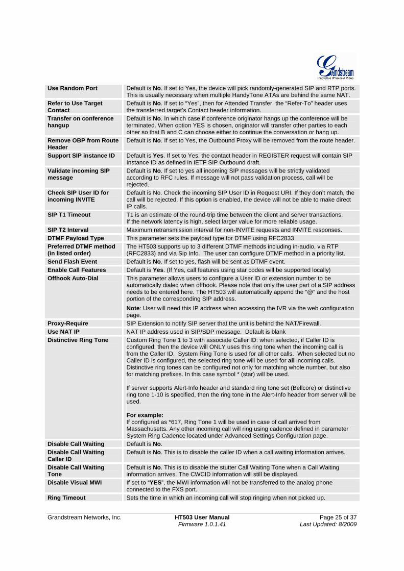
Use Random Port Default is No. If set to Yes, the device will pick randomly-generated SIP and RTP ports. This is usually necessary when multiple HandyTone ATAs are behind the same NAT.
Refer to Use Target Contact
Default is No. If set to “Yes”, then for Attended Transfer, the “Refer-To” header uses the transferred target’s Contact header information.
Transfer on conference hangup
Default is No. In which case if conference originator hangs up the conference will be terminated. When option YES is chosen, originator will transfer other parties to each other so that B and C can choose either to continue the conversation or hang up.
Remove OBP from Route Header
Default is No. If set to Yes, the Outbound Proxy will be removed from the route header.
Support SIP instance ID Default is Yes. If set to Yes, the contact header in REGISTER request will contain SIP Instance ID as defined in IETF SIP Outbound draft.
Validate incoming SIP message
Default is No. If set to yes all incoming SIP messages will be strictly validated according to RFC rules. If message will not pass validation process, call will be rejected.
Check SIP User ID for incoming INVITE
Default is No. Check the incoming SIP User ID in Request URI. If they don’t match, the call will be rejected. If this option is enabled, the device will not be able to make direct IP calls.
SIP T1 Timeout T1 is an estimate of the round-trip time between the client and server transactions. If the network latency is high, select larger value for more reliable usage.
SIP T2 Interval Maximum retransmission interval for non-INVITE requests and INVITE responses. DTMF Payload Type This parameter sets the payload type for DTMF using RFC2833 Preferred DTMF method (in listed order)
The HT503 supports up to 3 different DTMF methods including in-audio, via RTP (RFC2833) and via Sip Info. The user can configure DTMF method in a priority list.
Send Flash Event Default is No. If set to yes, flash will be sent as DTMF event. Enable Call Features Default is Yes. (If Yes, call features using star codes will be supported locally) Offhook Auto-Dial This parameter allows users to configure a User ID or extension number to be
automatically dialed when offhook. Please note that only the user part of a SIP address needs to be entered here. The HT503 will automatically append the “@” and the host portion of the corresponding SIP address. Note: User will need this IP address when accessing the IVR via the web configuration page.
Proxy-Require SIP Extension to notify SIP server that the unit is behind the NAT/Firewall. Use NAT IP NAT IP address used in SIP/SDP message. Default is blank Distinctive Ring Tone Custom Ring Tone 1 to 3 with associate Caller ID: when selected, if Caller ID is
configured, then the device will ONLY uses this ring tone when the incoming call is from the Caller ID. System Ring Tone is used for all other calls. When selected but no Caller ID is configured, the selected ring tone will be used for all incoming calls. Distinctive ring tones can be configured not only for matching whole number, but also for matching prefixes. In this case symbol * (star) will be used. If server supports Alert-Info header and standard ring tone set (Bellcore) or distinctive ring tone 1-10 is specified, then the ring tone in the Alert-Info header from server will be used. For example: If configured as *617, Ring Tone 1 will be used in case of call arrived from Massachusetts. Any other incoming call will ring using cadence defined in parameter System Ring Cadence located under Advanced Settings Configuration page.
Disable Call Waiting Default is No. Disable Call Waiting Caller ID
Default is No. This is to disable the caller ID when a call waiting information arrives.
Disable Call Waiting Tone
Default is No. This is to disable the stutter Call Waiting Tone when a Call Waiting information arrives. The CWCID information will still be displayed.
Disable Visual MWI If set to “YES”, the MWI information will not be transferred to the analog phone connected to the FXS port.
Ring Timeout Sets the time in which an incoming call will stop ringing when not picked up.
Grandstream Networks, Inc. HT503 User Manual Page 26 of 37 Firmware 1.0.1.41 Last Updated: 8/2009
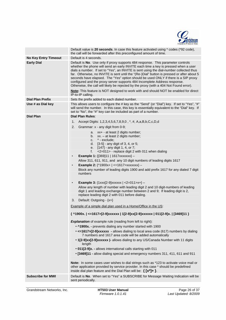
Default value is 20 seconds. In case this feature activated using * codes (*92 code), the call will be forwarded after this preconfigured amount of time.
No Key Entry Timeout Default is 4 seconds. Early Dial Default is No. Use only if proxy supports 484 response. This parameter controls
whether the phone will send an early INVITE each time a key is pressed when a user dials a number. If set to “Yes”, an INVITE is sent using the dial-number collected thus far. Otherwise, no INVITE is sent until the “(Re-)Dial” button is pressed or after about 5 seconds have elapsed. The “Yes” option should be used ONLY if there is a SIP proxy configured and the proxy server supports 484 Incomplete Address response. Otherwise, the call will likely be rejected by the proxy (with a 404 Not Found error). Note: This feature is NOT designed to work with and should NOT be enabled for direct IP-to-IP calling.
Dial Plan Prefix Sets the prefix added to each dialed number. Use # as Dial key This allows users to configure the # key as the “Send” (or “Dial”) key. If set to “Yes”, “#”
will send the number. In this case, this key is essentially equivalent to the “Dial” key. If set to “No”, the “#” key can be included as part of a number.
Dial Plan Dial Plan Rules: 1. Accept Digits: 1,2,3,4,5,6,7,8,9,0 , *, #, A,a,B,b,C,c,D,d 2. Grammar: x - any digit from 0-9;
a. xx+ - at least 2 digits number; b. xx. – at least 2 digits number; c. ^ - exclude; d. [3-5] - any digit of 3, 4, or 5; e. [147] - any digit 1, 4, or 7; f. <2=011> - replace digit 2 with 011 when dialing
• Example 1: {[369]11 | 1617xxxxxxx} – Allow 311, 611, 911, and any 10 digit numbers of leading digits 1617
• Example 2: {^1900x+ | <=1617>xxxxxxx} – Block any number of leading digits 1900 and add prefix 1617 for any dialed 7 digit numbers
• Example 3: {1xxx[2-9]xxxxxx | <2=011>x+} – Allow any length of number with leading digit 2 and 10 digit-numbers of leading digit 1 and leading exchange number between 2 and 9; If leading digit is 2, replace leading digit 2 with 011 before dialing.
3. Default: Outgoing - {x+}
Example of a simple dial plan used in a Home/Office in the US: { ^1900x. | <=1617>[2-9]xxxxxx | 1[2-9]xx[2-9]xxxxxx | 011[2-9]x. | [3469]11 } Explanation of example rule (reading from left to right):
• ^1900x. - prevents dialing any number started with 1900 • <=1617>[2-9]xxxxxx - allows dialing to local area code (617) numbers by dialing
7 numbers and 1617 area code will be added automatically • 1[2-9]xx[2-9]xxxxxx |- allows dialing to any US/Canada Number with 11 digits
length • 011[2-9]x. - allows international calls starting with 011 • [3469]11 - allow dialing special and emergency numbers 311, 411, 611 and 911
Note: In some cases user wishes to dial strings such as *123 to activate voice mail or other application provided by service provider. In this case * should be predefined inside dial plan feature and the Dial Plan will be: { [x*]+ }.
Subscribe for MWI Default is No. When set to “Yes” a SUBSCRIBE for Message Waiting Indication will be sent periodically.
Grandstream Networks, Inc. HT503 User Manual Page 27 of 37 Firmware 1.0.1.41 Last Updated: 8/2009
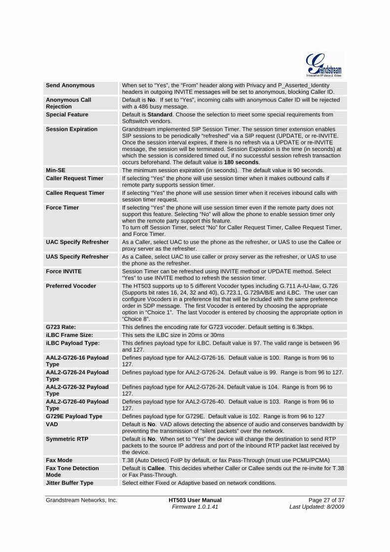
Send Anonymous When set to “Yes”, the “From” header along with Privacy and P_Asserted_Identity headers in outgoing INVITE messages will be set to anonymous, blocking Caller ID.
Anonymous Call Rejection
Default is No. If set to “Yes”, incoming calls with anonymous Caller ID will be rejected with a 486 busy message.
Special Feature Default is Standard. Choose the selection to meet some special requirements from Softswitch vendors.
Session Expiration Grandstream implemented SIP Session Timer. The session timer extension enables SIP sessions to be periodically “refreshed” via a SIP request (UPDATE, or re-INVITE. Once the session interval expires, if there is no refresh via a UPDATE or re-INVITE message, the session will be terminated. Session Expiration is the time (in seconds) at which the session is considered timed out, if no successful session refresh transaction occurs beforehand. The default value is 180 seconds.
Min-SE The minimum session expiration (in seconds). The default value is 90 seconds. Caller Request Timer If selecting “Yes” the phone will use session timer when it makes outbound calls if
remote party supports session timer. Callee Request Timer If selecting “Yes” the phone will use session timer when it receives inbound calls with
session timer request. Force Timer If selecting “Yes” the phone will use session timer even if the remote party does not
support this feature. Selecting “No” will allow the phone to enable session timer only when the remote party support this feature. To turn off Session Timer, select “No” for Caller Request Timer, Callee Request Timer, and Force Timer.
UAC Specify Refresher As a Caller, select UAC to use the phone as the refresher, or UAS to use the Callee or proxy server as the refresher.
UAS Specify Refresher As a Callee, select UAC to use caller or proxy server as the refresher, or UAS to use the phone as the refresher.
Force INVITE Session Timer can be refreshed using INVITE method or UPDATE method. Select “Yes” to use INVITE method to refresh the session timer.
Preferred Vocoder The HT503 supports up to 5 different Vocoder types including G.711 A-/U-law, G.726 (Supports bit rates 16, 24, 32 and 40), G.723.1, G.729A/B/E and iLBC. The user can configure Vocoders in a preference list that will be included with the same preference order in SDP message. The first Vocoder is entered by choosing the appropriate option in “Choice 1”. The last Vocoder is entered by choosing the appropriate option in “Choice 8”.
G723 Rate: This defines the encoding rate for G723 vocoder. Default setting is 6.3kbps. iLBC Frame Size: This sets the iLBC size in 20ms or 30ms iLBC Payload Type: This defines payload type for iLBC. Default value is 97. The valid range is between 96
and 127. AAL2-G726-16 Payload Type
Defines payload type for AAL2-G726-16. Default value is 100. Range is from 96 to 127.
AAL2-G726-24 Payload Type
Defines payload type for AAL2-G726-24. Default value is 99. Range is from 96 to 127.
AAL2-G726-32 Payload Type
Defines payload type for AAL2-G726-24. Default value is 104. Range is from 96 to 127.
AAL2-G726-40 Payload Type
Defines payload type for AAL2-G726-40. Default value is 103. Range is from 96 to 127.
G729E Payload Type Defines payload type for G729E. Default value is 102. Range is from 96 to 127 VAD Default is No. VAD allows detecting the absence of audio and conserves bandwidth by
preventing the transmission of “silent packets” over the network. Symmetric RTP Default is No. When set to “Yes” the device will change the destination to send RTP
packets to the source IP address and port of the inbound RTP packet last received by the device.
Fax Mode T.38 (Auto Detect) FoIP by default, or fax Pass-Through (must use PCMU/PCMA) Fax Tone Detection Mode
Default is Callee. This decides whether Caller or Callee sends out the re-invite for T.38 or Fax Pass-Through.
Jitter Buffer Type Select either Fixed or Adaptive based on network conditions.
Grandstream Networks, Inc. HT503 User Manual Page 28 of 37 Firmware 1.0.1.41 Last Updated: 8/2009
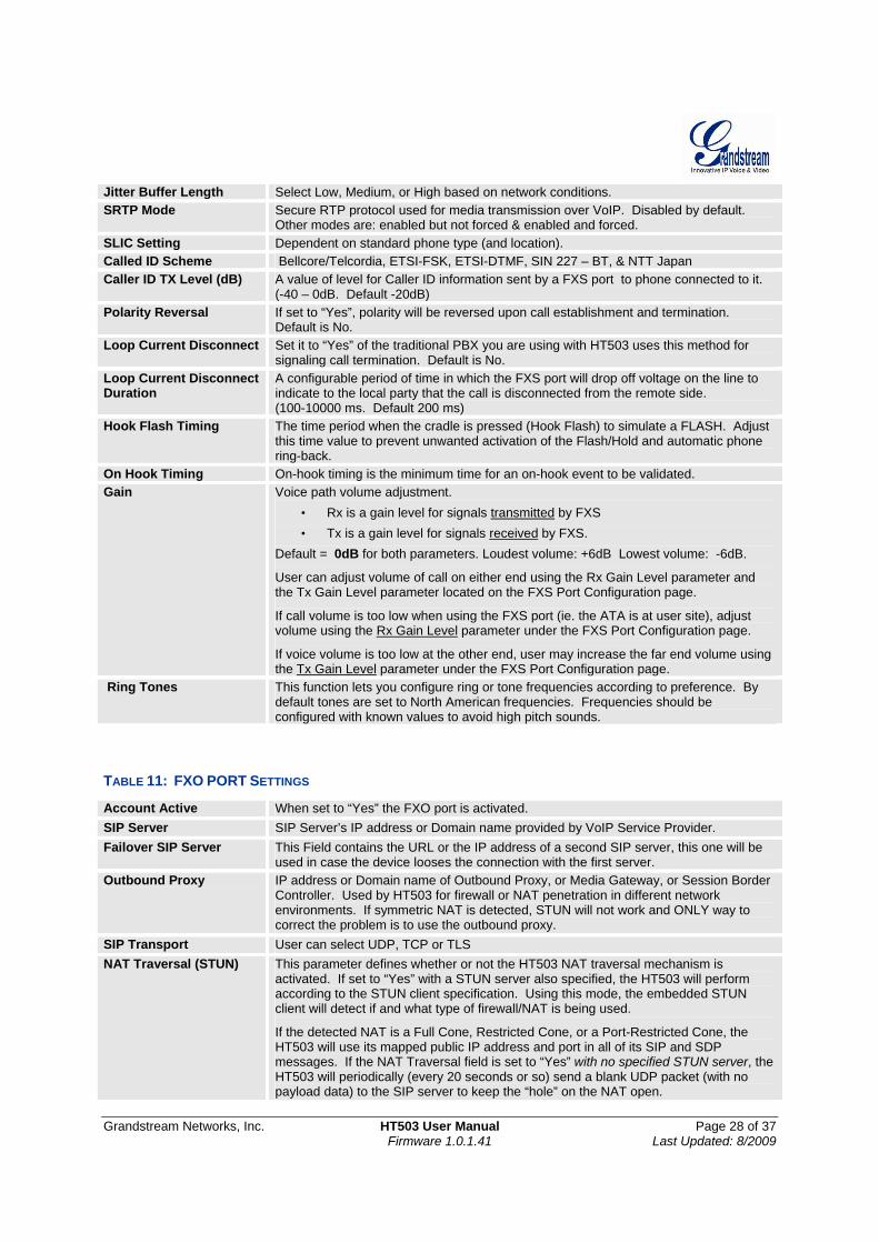
Jitter Buffer Length Select Low, Medium, or High based on network conditions. SRTP Mode Secure RTP protocol used for media transmission over VoIP. Disabled by default.
Other modes are: enabled but not forced & enabled and forced. SLIC Setting Dependent on standard phone type (and location). Called ID Scheme Bellcore/Telcordia, ETSI-FSK, ETSI-DTMF, SIN 227 – BT, & NTT Japan Caller ID TX Level (dB) A value of level for Caller ID information sent by a FXS port to phone connected to it.
(-40 – 0dB. Default -20dB) Polarity Reversal If set to “Yes”, polarity will be reversed upon call establishment and termination.
Default is No. Loop Current Disconnect Set it to “Yes” of the traditional PBX you are using with HT503 uses this method for
signaling call termination. Default is No. Loop Current Disconnect Duration
A configurable period of time in which the FXS port will drop off voltage on the line to indicate to the local party that the call is disconnected from the remote side. (100-10000 ms. Default 200 ms)
Hook Flash Timing The time period when the cradle is pressed (Hook Flash) to simulate a FLASH. Adjust this time value to prevent unwanted activation of the Flash/Hold and automatic phone ring-back.
On Hook Timing On-hook timing is the minimum time for an on-hook event to be validated. Gain Voice path volume adjustment.
• Rx is a gain level for signals transmitted by FXS • Tx is a gain level for signals received by FXS.
Default = 0dB for both parameters. Loudest volume: +6dB Lowest volume: -6dB.
User can adjust volume of call on either end using the Rx Gain Level parameter and the Tx Gain Level parameter located on the FXS Port Configuration page.
If call volume is too low when using the FXS port (ie. the ATA is at user site), adjust volume using the Rx Gain Level parameter under the FXS Port Configuration page.
If voice volume is too low at the other end, user may increase the far end volume using the Tx Gain Level parameter under the FXS Port Configuration page.
Ring Tones This function lets you configure ring or tone frequencies according to preference. By default tones are set to North American frequencies. Frequencies should be configured with known values to avoid high pitch sounds.
TABLE 11: FXO PORT SETTINGS
Account Active When set to “Yes” the FXO port is activated. SIP Server SIP Server’s IP address or Domain name provided by VoIP Service Provider. Failover SIP Server This Field contains the URL or the IP address of a second SIP server, this one will be
used in case the device looses the connection with the first server. Outbound Proxy IP address or Domain name of Outbound Proxy, or Media Gateway, or Session Border
Controller. Used by HT503 for firewall or NAT penetration in different network environments. If symmetric NAT is detected, STUN will not work and ONLY way to correct the problem is to use the outbound proxy.
SIP Transport User can select UDP, TCP or TLS NAT Traversal (STUN) This parameter defines whether or not the HT503 NAT traversal mechanism is
activated. If set to “Yes” with a STUN server also specified, the HT503 will perform according to the STUN client specification. Using this mode, the embedded STUN client will detect if and what type of firewall/NAT is being used.
If the detected NAT is a Full Cone, Restricted Cone, or a Port-Restricted Cone, the HT503 will use its mapped public IP address and port in all of its SIP and SDP messages. If the NAT Traversal field is set to “Yes” with no specified STUN server, the HT503 will periodically (every 20 seconds or so) send a blank UDP packet (with no payload data) to the SIP server to keep the “hole” on the NAT open.
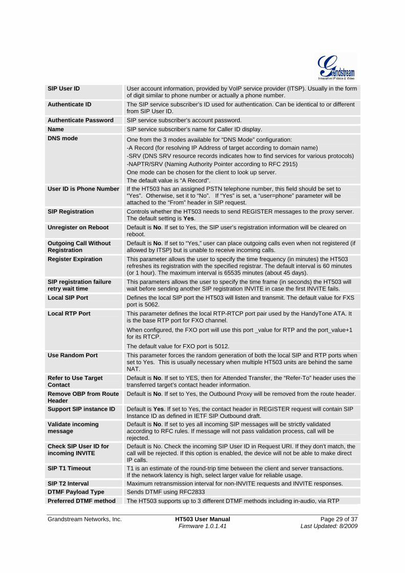
Grandstream Networks, Inc. HT503 User Manual Page 29 of 37 Firmware 1.0.1.41 Last Updated: 8/2009
SIP User ID User account information, provided by VoIP service provider (ITSP). Usually in the form of digit similar to phone number or actually a phone number.
Authenticate ID The SIP service subscriber’s ID used for authentication. Can be identical to or different from SIP User ID.
Authenticate Password SIP service subscriber’s account password. Name SIP service subscriber’s name for Caller ID display. DNS mode One from the 3 modes available for “DNS Mode” configuration:
-A Record (for resolving IP Address of target according to domain name) -SRV (DNS SRV resource records indicates how to find services for various protocols) -NAPTR/SRV (Naming Authority Pointer according to RFC 2915) One mode can be chosen for the client to look up server. The default value is “A Record”.
User ID is Phone Number If the HT503 has an assigned PSTN telephone number, this field should be set to “Yes”. Otherwise, set it to “No”. If “Yes” is set, a “user=phone” parameter will be attached to the “From” header in SIP request.
SIP Registration Controls whether the HT503 needs to send REGISTER messages to the proxy server. The default setting is Yes.
Unregister on Reboot Default is No. If set to Yes, the SIP user’s registration information will be cleared on reboot.
Outgoing Call Without Registration
Default is No. If set to “Yes,” user can place outgoing calls even when not registered (if allowed by ITSP) but is unable to receive incoming calls.
Register Expiration This parameter allows the user to specify the time frequency (in minutes) the HT503 refreshes its registration with the specified registrar. The default interval is 60 minutes (or 1 hour). The maximum interval is 65535 minutes (about 45 days).
SIP registration failure retry wait time
This parameters allows the user to specify the time frame (in seconds) the HT503 will wait before sending another SIP registration INVITE in case the first INVITE fails.
Local SIP Port Defines the local SIP port the HT503 will listen and transmit. The default value for FXS port is 5062.
Local RTP Port This parameter defines the local RTP-RTCP port pair used by the HandyTone ATA. It is the base RTP port for FXO channel. When configured, the FXO port will use this port _value for RTP and the port_value+1 for its RTCP. The default value for FXO port is 5012.
Use Random Port This parameter forces the random generation of both the local SIP and RTP ports when set to Yes. This is usually necessary when multiple HT503 units are behind the same NAT.
Refer to Use Target Contact
Default is No. If set to YES, then for Attended Transfer, the “Refer-To” header uses the transferred target’s contact header information.
Remove OBP from Route Header
Default is No. If set to Yes, the Outbound Proxy will be removed from the route header.
Support SIP instance ID Default is Yes. If set to Yes, the contact header in REGISTER request will contain SIP Instance ID as defined in IETF SIP Outbound draft.
Validate incoming message
Default is No. If set to yes all incoming SIP messages will be strictly validated according to RFC rules. If message will not pass validation process, call will be rejected.
Check SIP User ID for incoming INVITE
Default is No. Check the incoming SIP User ID in Request URI. If they don’t match, the call will be rejected. If this option is enabled, the device will not be able to make direct IP calls.
SIP T1 Timeout T1 is an estimate of the round-trip time between the client and server transactions. If the network latency is high, select larger value for reliable usage.
SIP T2 Interval Maximum retransmission interval for non-INVITE requests and INVITE responses. DTMF Payload Type Sends DTMF using RFC2833 Preferred DTMF method The HT503 supports up to 3 different DTMF methods including in-audio, via RTP
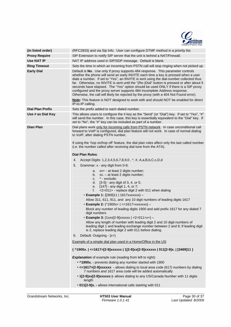
Grandstream Networks, Inc. HT503 User Manual Page 30 of 37 Firmware 1.0.1.41 Last Updated: 8/2009
(in listed order) (RFC2833) and via Sip Info. User can configure DTMF method in a priority list. Proxy Require SIP Extension to notify SIP server that the unit is behind a NAT/Firewall. Use NAT IP NAT IP address used in SIP/SDP message. Default is blank. Ring Timeout Sets the time in which an incoming from PSTN call will stop ringing when not picked up.Early Dial Default is No. Use only if proxy supports 484 response. This parameter controls
whether the phone will send an early INVITE each time a key is pressed when a user dials a number. If set to “Yes”, an INVITE is sent using the dial-number collected thus far. Otherwise, no INVITE is sent until the “(Re-)Dial” button is pressed or after about 5 seconds have elapsed. The “Yes” option should be used ONLY if there is a SIP proxy configured and the proxy server supports 484 Incomplete Address response. Otherwise, the call will likely be rejected by the proxy (with a 404 Not Found error). Note: This feature is NOT designed to work with and should NOT be enabled for direct IP-to-IP calling.
Dial Plan Prefix Sets the prefix added to each dialed number. Use # as Dial Key This allows users to configure the # key as the “Send” (or “Dial”) key. If set to “Yes”, “#”
will send the number. In this case, this key is essentially equivalent to the “Dial” key. If set to “No”, the “#” key can be included as part of a number.
Dian Plan Dial plans work only for incoming calls from PSTN network. In case unconditional call forward to VoIP is configured, dial plan feature will not work. In case of normal dialing to VoIP, after dialing PSTN number, If using the ‘hop on/hop off’ feature, the dial plan rules affect only the last called number (i.e. the number called after receiving dial tone from the ATA). Dial Plan Rules: 4. Accept Digits: 1,2,3,4,5,6,7,8,9,0 , *, #, A,a,B,b,C,c,D,d 5. Grammar: x - any digit from 0-9;
a. xx+ - at least 2 digits number; b. xx. – at least 2 digits number; c. ^ - exclude; d. [3-5] - any digit of 3, 4, or 5; e. [147] - any digit 1, 4, or 7; f. <2=011> - replace digit 2 with 011 when dialing
• Example 1: {[369]11 | 1617xxxxxxx} – Allow 311, 611, 911, and any 10 digit numbers of leading digits 1617
• Example 2: {^1900x+ | <=1617>xxxxxxx} – Block any number of leading digits 1900 and add prefix 1617 for any dialed 7 digit numbers
• Example 3: {1xxx[2-9]xxxxxx | <2=011>x+} – Allow any length of number with leading digit 2 and 10 digit-numbers of leading digit 1 and leading exchange number between 2 and 9; If leading digit is 2, replace leading digit 2 with 011 before dialing.
6. Default: Outgoing - {x+}
Example of a simple dial plan used in a Home/Office in the US: { ^1900x. | <=1617>[2-9]xxxxxx | 1[2-9]xx[2-9]xxxxxx | 011[2-9]x. | [3469]11 } Explanation of example rule (reading from left to right):
• ^1900x. - prevents dialing any number started with 1900 • <=1617>[2-9]xxxxxx - allows dialing to local area code (617) numbers by dialing
7 numbers and 1617 area code will be added automatically • 1[2-9]xx[2-9]xxxxxx |- allows dialing to any US/Canada Number with 11 digits
length • 011[2-9]x. - allows international calls starting with 011
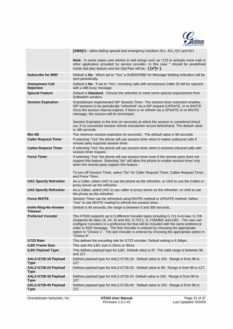
Grandstream Networks, Inc. HT503 User Manual Page 31 of 37 Firmware 1.0.1.41 Last Updated: 8/2009
[3469]11 - allow dialing special and emergency numbers 311, 411, 611 and 911 Note: In some cases user wishes to dial strings such as *123 to activate voice mail or other application provided by service provider. In this case * should be predefined inside dial plan feature and the Dial Plan will be: { [x*]+ }.
Subscribe for MWI Default is No. When set to “Yes” a SUBSCRIBE for Message Waiting Indication will be sent periodically.
Anonymous Call Rejection
Default is No. If set to “Yes”, incoming calls with anonymous Caller ID will be rejected with a 486 busy message.
Special Feature Default is Standard. Choose the selection to meet some special requirements from Softswitch vendors.
Session Expiration Grandstream implemented SIP Session Timer. The session timer extension enables SIP sessions to be periodically “refreshed” via a SIP request (UPDATE, or re-INVITE. Once the session interval expires, if there is no refresh via a UPDATE or re-INVITE message, the session will be terminated. Session Expiration is the time (in seconds) at which the session is considered timed out, if no successful session refresh transaction occurs beforehand. The default value is 180 seconds.
Min-SE The minimum session expiration (in seconds). The default value is 90 seconds. Caller Request Timer If selecting “Yes” the phone will use session timer when it makes outbound calls if
remote party supports session timer. Callee Request Timer If selecting “Yes” the phone will use session timer when it receives inbound calls with
session timer request. Force Timer If selecting “Yes” the phone will use session timer even if the remote party does not
support this feature. Selecting “No” will allow the phone to enable session timer only when the remote party support this feature. To turn off Session Timer, select “No” for Caller Request Timer, Callee Request Timer, and Force Timer.
UAC Specify Refresher As a Caller, select UAC to use the phone as the refresher, or UAS to use the Callee or proxy server as the refresher.
UAS Specify Refresher As a Callee, select UAC to use caller or proxy server as the refresher, or UAS to use the phone as the refresher.
Force INVITE Session Timer can be refreshed using INVITE method or UPDATE method. Select “Yes” to use INVITE method to refresh the session timer.
Invite Ring-No-Answer Timeout
Default is 40 seconds, the range is between 5 and 300 seconds.
Preferred Vocoder The HT503 supports up to 5 different Vocoder types including G.711 A-/U-law, G.726 (Supports bit rates 16, 24, 32 and 40), G.723.1, G.729A/B/E and iLBC. The user can configure Vocoders in a preference list that will be included with the same preference order in SDP message. The first Vocoder is entered by choosing the appropriate option in “Choice 1”. The last Vocoder is entered by choosing the appropriate option in “Choice 8”.
G723 Rate: This defines the encoding rate for G723 vocoder. Default setting is 6.3kbps. iLBC Frame Size: This sets the iLBC size in 20ms or 30ms iLBC Payload Type: This defines payload type for iLBC. Default value is 97. The valid range is between 96
and 127. AAL2-G726-16 Payload Type
Defines payload type for AAL2-G726-16. Default value is 100. Range is from 96 to 127.
AAL2-G726-24 Payload Type
Defines payload type for AAL2-G726-24. Default value is 99. Range is from 96 to 127.
AAL2-G726-32 Payload Type
Defines payload type for AAL2-G726-24. Default value is 104. Range is from 96 to 127.
AAL2-G726-40 Payload Type
Defines payload type for AAL2-G726-40. Default value is 103. Range is from 96 to 127.
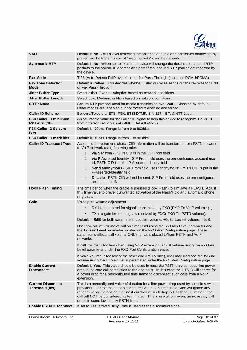
Grandstream Networks, Inc. HT503 User Manual Page 32 of 37 Firmware 1.0.1.41 Last Updated: 8/2009
VAD Default is No. VAD allows detecting the absence of audio and conserves bandwidth by preventing the transmission of “silent packets” over the network.
Symmetric RTP Default is No. When set to “Yes” the device will change the destination to send RTP packets to the source IP address and port of the inbound RTP packet last received by the device.
Fax Mode T.38 (Auto Detect) FoIP by default, or fax Pass-Through (must use PCMU/PCMA) Fax Tone Detection Mode
Default is Callee. This decides whether Caller or Callee sends out the re-invite for T.38 or Fax Pass-Through.
Jitter Buffer Type Select either Fixed or Adaptive based on network conditions. Jitter Buffer Length Select Low, Medium, or High based on network conditions. SRTP Mode Secure RTP protocol used for media transmission over VoIP. Disabled by default.
Other modes are: enabled but not forced & enabled and forced. Caller ID Scheme Bellcore/Telcordia, ETSI-FSK, ETSI-DTMF, SIN 227 – BT, & NTT Japan FSK Caller ID minimum RX Level (dB)
An adjustable value for the Caller ID signal to help this device to recognize Caller ID from different networks. (-96 -0dB. Default -40dB)
FSK Caller ID Seizure Bits
Default is: 70bits. Range is from 0 to 800bits.
FSK Caller ID mark bits Default is: 40bits. Range is from 1 to 800bits. Caller ID Transport Type According to customer’s choice CID information will be transferred from PSTN network
to VoIP network using following rules: 1. via SIP from - PSTN CID is in the SIP From field 2. via P-Asserted-Identity - SIP From field uses the pre-configured account user
Id. PSTN CID is in the P-Asserted-Identity field 3. Send anonymous - SIP From field uses "anonymous". PSTN CID is put in the
P-Asserted-Identity field 4. Disable - PSTN CID will not be sent. SIP From field uses the pre-configured
account user ID
Hook Flash Timing The time period when the cradle is pressed (Hook Flash) to simulate a FLASH. Adjust this time value to prevent unwanted activation of the Flash/Hold and automatic phone ring-back.
Gain Voice path volume adjustment. • RX is a gain level for signals transmitted by FXO (FXO-To-VoIP volume ) , • TX is a gain level for signals received by FXO( FXO-To-PSTN volume).
Default = 0dB for both parameters. Loudest volume: +6dB; Lowest volume: -6dB.
User can adjust volume of call on either end using the Rx Gain Level parameter and the Tx Gain Level parameter located on the FXO Port Configuration page. These parameters affects call volume ONLY for calls placed to/from PSTN and VoIP networks.
If call volume is too low when using VoIP extension, adjust volume using the Rx Gain Level parameter under the FXO Port Configuration page.
If voice volume is too low at the other end (PSTN side), user may increase the far end volume using the Tx Gain Level parameter under the FXO Port Configuration page.
Enable Current Disconnect
Default is Yes. This value should be used in case the PSTN provider uses line power drop to indicate call completion to the end point. In this case the HT503 will search for a power drop for a preconfigured time frame to disconnect such calls from a VoIP extension.
Current Disconnect Threshold (ms)
This is a preconfigured value of duration for a line power drop used by specific service providers. For example, for a configured value of 500ms the device will ignore any random voltage drops on the line if duration of such drop is less than 500ms and the call will NOT be considered as terminated. This is useful to prevent unnecessary call drops in some low quality PSTN lines.
Enable PSTN Disconnect If set to Yes, arrived Busy Tone is used as the disconnect signal.
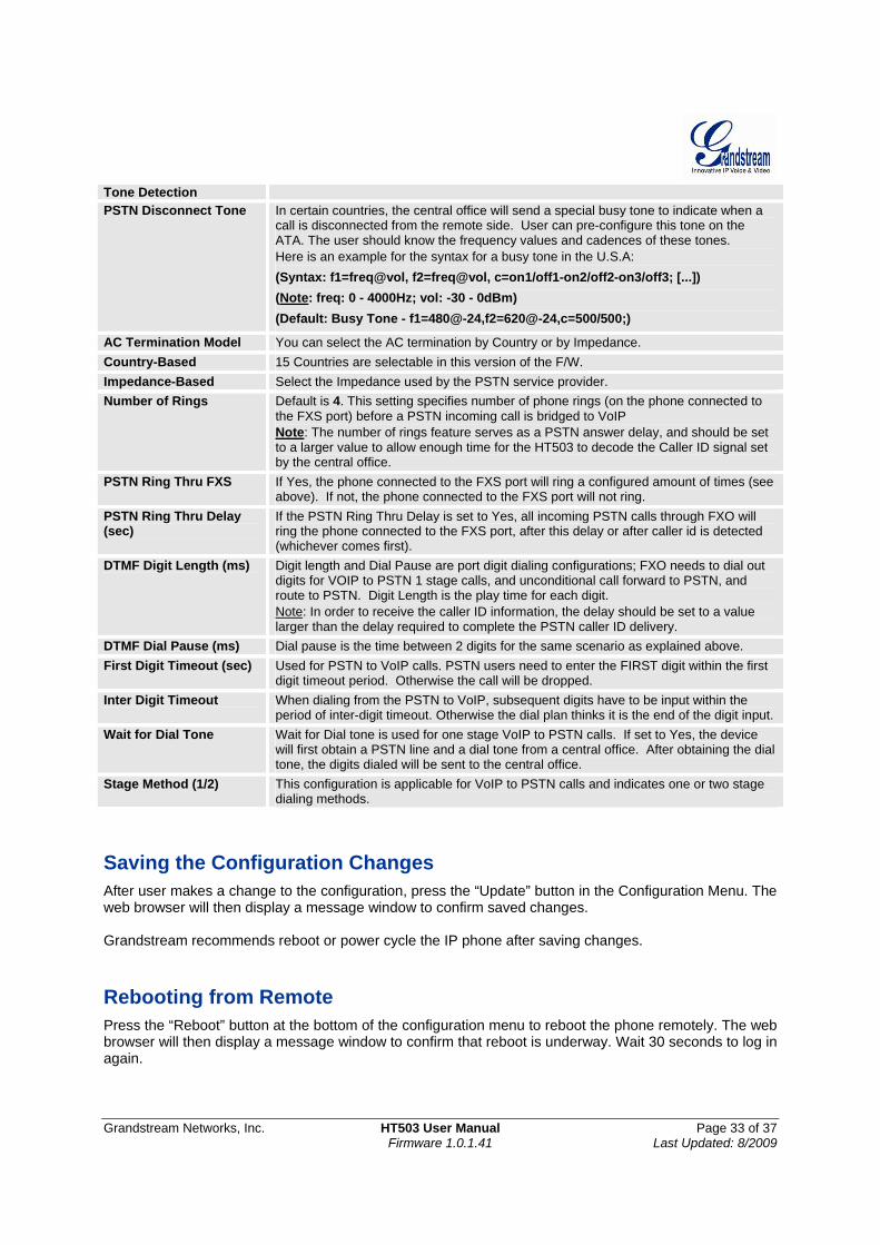
Grandstream Networks, Inc. HT503 User Manual Page 33 of 37 Firmware 1.0.1.41 Last Updated: 8/2009
Tone Detection PSTN Disconnect Tone In certain countries, the central office will send a special busy tone to indicate when a
call is disconnected from the remote side. User can pre-configure this tone on the ATA. The user should know the frequency values and cadences of these tones. Here is an example for the syntax for a busy tone in the U.S.A: (Syntax: f1=freq@vol, f2=freq@vol, c=on1/off1-on2/off2-on3/off3; [...]) (Note: freq: 0 - 4000Hz; vol: -30 - 0dBm) (Default: Busy Tone - f1=480@-24,f2=620@-24,c=500/500;)
AC Termination Model You can select the AC termination by Country or by Impedance. Country-Based 15 Countries are selectable in this version of the F/W. Impedance-Based Select the Impedance used by the PSTN service provider. Number of Rings Default is 4. This setting specifies number of phone rings (on the phone connected to
the FXS port) before a PSTN incoming call is bridged to VoIP Note: The number of rings feature serves as a PSTN answer delay, and should be set to a larger value to allow enough time for the HT503 to decode the Caller ID signal set by the central office.
PSTN Ring Thru FXS If Yes, the phone connected to the FXS port will ring a configured amount of times (see above). If not, the phone connected to the FXS port will not ring.
PSTN Ring Thru Delay (sec)
If the PSTN Ring Thru Delay is set to Yes, all incoming PSTN calls through FXO will ring the phone connected to the FXS port, after this delay or after caller id is detected (whichever comes first).
DTMF Digit Length (ms) Digit length and Dial Pause are port digit dialing configurations; FXO needs to dial out digits for VOIP to PSTN 1 stage calls, and unconditional call forward to PSTN, and route to PSTN. Digit Length is the play time for each digit. Note: In order to receive the caller ID information, the delay should be set to a value larger than the delay required to complete the PSTN caller ID delivery.
DTMF Dial Pause (ms) Dial pause is the time between 2 digits for the same scenario as explained above. First Digit Timeout (sec) Used for PSTN to VoIP calls. PSTN users need to enter the FIRST digit within the first
digit timeout period. Otherwise the call will be dropped. Inter Digit Timeout When dialing from the PSTN to VoIP, subsequent digits have to be input within the
period of inter-digit timeout. Otherwise the dial plan thinks it is the end of the digit input.Wait for Dial Tone Wait for Dial tone is used for one stage VoIP to PSTN calls. If set to Yes, the device
will first obtain a PSTN line and a dial tone from a central office. After obtaining the dial tone, the digits dialed will be sent to the central office.
Stage Method (1/2) This configuration is applicable for VoIP to PSTN calls and indicates one or two stage dialing methods.
Saving the Configuration Changes After user makes a change to the configuration, press the “Update” button in the Configuration Menu. The web browser will then display a message window to confirm saved changes. Grandstream recommends reboot or power cycle the IP phone after saving changes.
Rebooting from Remote Press the “Reboot” button at the bottom of the configuration menu to reboot the phone remotely. The web browser will then display a message window to confirm that reboot is underway. Wait 30 seconds to log in again.
Grandstream Networks, Inc. HT503 User Manual Page 34 of 37 Firmware 1.0.1.41 Last Updated: 8/2009
Configuration through a Central Server Grandstream HT503 can be automatically configured from a central provisioning system. When HT503 boots up, it will send TFTP or HTTP request to download configuration file, “cfg000b82xxxxxx”, where “000b82xxxxxx” is the LAN MAC address of the HT503. A service provider or an enterprise with large deployment of Grandstream devices can easily manage the configuration and service provisioning of individual devices remotely from a central server.
Grandstream has a central provisioning system called GAPS (Grandstream Automated Provisioning System). GAPS supports automatic configuration of Grandstream devices. GAPS uses enhanced (NAT friendly) TFTP or HTTP (thus no NAT issues) and other communication protocols to communicate with each individual Grandstream device.
Grandstream provides GAPS service to VoIP service providers. Use GAPS for either simple redirection or with certain special provisioning settings. At boot-up, Grandstream devices by default point to Grandstream provisioning server GAPS, based on the unique MAC address of each device, GAPS provision the devices with redirection settings so that they will be redirected to customer’s TFTP or HTTP server for further provisioning. Grandstream also provide GAPSLITE software package which contains our NAT friendly TFTP server and a configuration tool to facilitate the task of generating device configuration files.
The GAPSLITE configuration tool is now free to end users. The tool and configuration template are available for download from http://www.grandstream.com/support/configurationtool.html.
Grandstream Networks, Inc. HT503 User Manual Page 35 of 37 Firmware 1.0.1.41 Last Updated: 8/2009
SOFTWARE UPGRADE Software upgrade can be done via either TFTP, HTTP or HTTPS. The corresponding configuration settings are in the ADVANCED SETTINGS configuration page. Firmware Upgrade through TFTP/HTTP/HTTPS To upgrade via TFTP, HTTP or HTTPS, the “Firmware Upgrade and Provisioning upgrade via” field needs to be set to TFTP, HTTP or HTTPS, respectively. “Firmware Server Path” needs to be set to a valid URL of a TFTP or HTTP server, server name can be in either FQDN or IP address format. Here are examples of some valid URL.
e.g. firmware.mycompany.com:6688/Grandstream/1.0.1.41 e.g. 72.172.83.110
NOTES:
Firmware upgrade server in IP address format can be configured via IVR. Please refer to the CONFIGURATION GUIDE section for instructions. If the server is in FQDN format, it must be set via the web configuration interface.
Grandstream recommends end-user use the Grandstream HTTP server. Its address can be
found at http://www.grandstream.com/firmware.html. Currently the HTTP firmware server IP address is 72.172.83.110. For large companies, we recommend to maintain their own TFTP/ HTTP/HTTPS server for upgrade and provisioning procedures.
Once a “Firmware Server Path” is set, user needs to update the settings and reboot the device. If
the configured firmware server is found and a new code image is available, the HT503 will attempt to retrieve the new image files by downloading them into the HT503 ’s SRAM. During this stage, the HT503’s LEDs will blink until the checking/downloading process is completed. Upon verification of checksum, the new code image will then be saved into the Flash. If TFTP/HTTP/HTTPS fails for any reason (e.g. TFTP/HTTP/HTTPS server is not responding, there are no code image files available for upgrade, or checksum test fails, etc), the HT503 will stop the TFTP/HTTP/HTTPS process and simply boot using the existing code image in the flash.
Firmware upgrade may take as long as 15 to 30 minutes over Internet, or just 5 minutes if it is performed on a LAN. It is recommended to conduct firmware upgrade in a controlled LAN environment if possible. For users who do not have a local firmware upgrade server, Grandstream provides a NAT-friendly HTTP server on the public Internet for firmware upgrade.
Grandstream’s latest firmware is available http://www.grandstream.com/firmware.html. Oversea users are strongly recommended to download the binary files and upgrade firmware locally in a controlled LAN environment.
Alternatively, user can download a free TFTP or HTTP server and conduct local firmware upgrade. A free windows version TFTP server is available for download from http://support.solarwinds.net/updates/New-customerFree.cfm. Our latest official release can be downloaded from http://www.grandstream.com/y-firmware.htm.
Instructions to download a free TFTP Server:
1. Unzip the file and put all of them under the root directory of the TFTP server. 2. Put the PC running the TFTP server and the HT503 device in the same LAN segment.
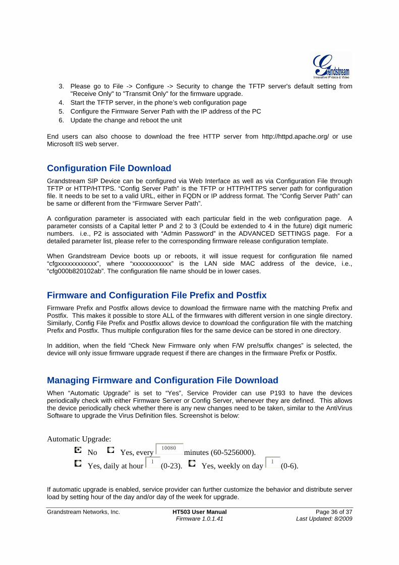
Grandstream Networks, Inc. HT503 User Manual Page 36 of 37 Firmware 1.0.1.41 Last Updated: 8/2009
3. Please go to File -> Configure -> Security to change the TFTP server's default setting from "Receive Only" to "Transmit Only" for the firmware upgrade.
4. Start the TFTP server, in the phone’s web configuration page 5. Configure the Firmware Server Path with the IP address of the PC 6. Update the change and reboot the unit
End users can also choose to download the free HTTP server from http://httpd.apache.org/ or use Microsoft IIS web server. Configuration File Download Grandstream SIP Device can be configured via Web Interface as well as via Configuration File through TFTP or HTTP/HTTPS. “Config Server Path” is the TFTP or HTTP/HTTPS server path for configuration file. It needs to be set to a valid URL, either in FQDN or IP address format. The “Config Server Path” can be same or different from the “Firmware Server Path”. A configuration parameter is associated with each particular field in the web configuration page. A parameter consists of a Capital letter P and 2 to 3 (Could be extended to 4 in the future) digit numeric numbers. i.e., P2 is associated with “Admin Password” in the ADVANCED SETTINGS page. For a detailed parameter list, please refer to the corresponding firmware release configuration template. When Grandstream Device boots up or reboots, it will issue request for configuration file named “cfgxxxxxxxxxxxx”, where “xxxxxxxxxxxx” is the LAN side MAC address of the device, i.e., “cfg000b820102ab”. The configuration file name should be in lower cases. Firmware and Configuration File Prefix and Postfix Firmware Prefix and Postfix allows device to download the firmware name with the matching Prefix and Postfix. This makes it possible to store ALL of the firmwares with different version in one single directory. Similarly, Config File Prefix and Postfix allows device to download the configuration file with the matching Prefix and Postfix. Thus multiple configuration files for the same device can be stored in one directory. In addition, when the field “Check New Firmware only when F/W pre/suffix changes” is selected, the device will only issue firmware upgrade request if there are changes in the firmware Prefix or Postfix. Managing Firmware and Configuration File Download When “Automatic Upgrade” is set to “Yes”, Service Provider can use P193 to have the devices periodically check with either Firmware Server or Config Server, whenever they are defined. This allows the device periodically check whether there is any new changes need to be taken, similar to the AntiVirus Software to upgrade the Virus Definition files. Screenshot is below: Automatic Upgrade:
No Yes, every 10080 minutes (60-5256000).
Yes, daily at hour 1 (0-23). Yes, weekly on day 1 (0-6). If automatic upgrade is enabled, service provider can further customize the behavior and distribute server load by setting hour of the day and/or day of the week for upgrade.
Grandstream Networks, Inc. HT503 User Manual Page 37 of 37 Firmware 1.0.1.41 Last Updated: 8/2009
RESTORE FACTORY DEFAULT SETTING WARNING! Restoring the Factory Default Setting will DELETE all configuration information of the phone. Please BACKUP or PRINT out all the settings before you approach to following steps. Grandstream will not take any responsibility if you lose all the parameters of setting and cannot connect to your VoIP service provider. FACTORY RESET
There are two (2) methods for resetting your unit: Reset Button Reset default factory settings following these four (4) steps:
1. Unplug the Ethernet cable.
2. Locate a needle-sized hole on the back panel of the gateway unit next to the power connection.
3. Insert a pin in this hole, and press for about 7 seconds.
4. Take out the pin. All unit settings are restored to factory settings. IVR Command Reset default factory settings using the IVR Prompt (Table 5):
1. Dial “***” for voice prompt. 2. Enter “99” and wait for “reset” voice prompt. 3. Enter the encoded MAC address (Look below on how to encode MAC address). 4. Wait 15 seconds and device will automatically reboot and restore factory settings.
Encode the MAC Address
1. Locate the MAC address of the device. It is the 12 digit HEX number on the bottom of the unit.
2. Key in the MAC address. Use the following mapping: 0-9: 0-9 A: 22 (press the “2” key twice, “A” will show on the LCD) B: 222 C: 2222 D: 33 (press the “3” key twice, “D” will show on the LCD) E: 333 F: 3333
For example: if the MAC address is 000b8200e395, it should be keyed in as “0002228200333395”.
NOTE: 1. Factory Reset will be disabled if the “Lock keypad update” is set to “Yes”. 2. Please be aware by default the HT503 WAN side HTTP access is disabled. After a factory reset, the
device’s web configuration page can be accessed only from its LAN port. 3. If the HT503 was previously locked by your local service provider, pressing the RESET button will
only restart the unit. The device will not return to factory default settings. 4. Please be aware if the RESET button was pressed and released in less than 7 seconds, the HT503
will only reboot, it won’t return to factory default settings.
Related Documents