MAKING MODERN LIVING POSSIBLE Technical Information Orbital Motors General powersolutions.danfoss.com

Welcome message from author
This document is posted to help you gain knowledge. Please leave a comment to let me know what you think about it! Share it to your friends and learn new things together.
Transcript
MAKING MODERN LIVING POSSIBLE
Technical Information
Orbital MotorsGeneral
powersolutions.danfoss.com
Revision history Table of revisions
Date Changed Rev
June 2015 Minimum speed updated 0202
May 2015 OMS version removed from section 'Motors woth integrated flushing valve CB
November 2014 Converted to Danfoss layout - DITA CMS CA
June 2005 BA
Technical Information General, Orbital Motors
2 520L0232 • Rev 0202 • June 2015
A wide range of Orbital MotorsCharacteristic, features and application areas of Orbital Motors....................................................................................5
Characteristic features of Danfoss Orbital Motors.......................................................................................................... 5Technical features of Danfoss Orbital Motor.....................................................................................................................5The Danfoss Orbital Motors are used in the following application areas:..............................................................6
Survey of literature with technical data on Danfoss Orbital Motors..............................................................................6
Conversion Factors
Orbital Motors, GeneralOperating Principle..........................................................................................................................................................................8
Gearwheel set...............................................................................................................................................................................8Distributor valve.......................................................................................................................................................................... 8
Spool valve...............................................................................................................................................................................8Disc valve with valve drive................................................................................................................................................. 9Disc valve on the output shaft.......................................................................................................................................... 9
Selection of Motor TypeOML, OMM, OMP, OMPW, DH....................................................................................................................................................10OMPW N............................................................................................................................................................................................ 10OMR, OMH, DS.................................................................................................................................................................................11OMRW N............................................................................................................................................................................................ 11OMEW.................................................................................................................................................................................................11OMS, OMT, OMV............................................................................................................................................................................. 11TMT......................................................................................................................................................................................................11Features of main types.................................................................................................................................................................11
OML, OMM, OMP, OMPW, DH.............................................................................................................................................. 11OMPW N.......................................................................................................................................................................................11OMR, OMH, DS........................................................................................................................................................................... 11OMRW N.......................................................................................................................................................................................12OMEW........................................................................................................................................................................................... 12OMS, OMT, OMV........................................................................................................................................................................12TMT................................................................................................................................................................................................ 12
Motor Variants.................................................................................................................................................................................12Motors with corrosion resistant parts............................................................................................................................... 12OMP/OMR with dust seal cap...............................................................................................................................................12Wheel motor...............................................................................................................................................................................13OMP/OMR with needle bearing.......................................................................................................................................... 13Super low leakage motor.......................................................................................................................................................13Short motors...............................................................................................................................................................................14Ultrashort motor....................................................................................................................................................................... 14Motors with integrated positive holding brake............................................................................................................ 14Motors with integrated negative holding brake...........................................................................................................14Motors with integrated flushing valve..............................................................................................................................15Motors with tacho connection............................................................................................................................................ 16Motors with speed sensor..................................................................................................................................................... 16OMT N motor..............................................................................................................................................................................16
Selection of Motor SizeBuild-up of the Function Diagram........................................................................................................................................... 17
Continuous operation/intermittent operation/peak load.........................................................................................17Efficiency......................................................................................................................................................................................18Volumetric efficiency...............................................................................................................................................................18Example........................................................................................................................................................................................18Hydraulic mechanical efficiency..........................................................................................................................................19Example:.......................................................................................................................................................................................19Total efficiency...........................................................................................................................................................................20
Use of the Function Diagram.....................................................................................................................................................20Minimum speed..............................................................................................................................................................................21
Bearing Dimensioning
Technical Information General, Orbital Motors
Contents
520L0232 • Rev 0202 • June 2015 3
Shaft load and bearing life time............................................................................................................................................... 22Relationship between Bearing Life Time and Speed........................................................................................................ 22Relationship between Shaft Load and Bearing Life Time................................................................................................23Relationship between permissible shaft load and speed............................................................................................... 23Maximum Radial Shaft Load...................................................................................................................................................... 23
Hydraulic SystemsMax. Pressure on the Shaft Seal................................................................................................................................................ 24
Standard shaft seal (NBR).......................................................................................................................................................24High-pressure shaft seal (NBR).............................................................................................................................................24Viton shaft seal (FPM)..............................................................................................................................................................24Characteristics of sealing materials....................................................................................................................................24
Motors with check valve................................................................................................................................................... 24Motors with drain line........................................................................................................................................................24Motors without check valve and drain line................................................................................................................25
OMEW........................................................................................................................................................................................... 25OMEW with high pressure shaft seal............................................................................................................................25CCW version (counter clockwise rotation)................................................................................................................. 25Short/ultra-short motors.................................................................................................................................................. 25
Drain Line..........................................................................................................................................................................................26Application..................................................................................................................................................................................26Oil flow in the drain line......................................................................................................................................................... 26
Braking............................................................................................................................................................................................... 26Braking torque........................................................................................................................................................................... 26Opening pressure for the dual shock valve.....................................................................................................................27Replenishment...........................................................................................................................................................................27Seeping.........................................................................................................................................................................................29
Brake Motors....................................................................................................................................................................................30OMS B............................................................................................................................................................................................30OMR F, OMT FX, OMT FL and TMT FL.................................................................................................................................30OMR F and OMT FH..................................................................................................................................................................31
Installation, Starting Up, Maintenance and Oil Types.......................................................................................................31Design in brief............................................................................................................................................................................31Combination in brief............................................................................................................................................................... 31Starting up and running in the hydraulic system......................................................................................................... 32Signs of air in the hydraulic system....................................................................................................................................32If there is air in the system.....................................................................................................................................................32During operation...................................................................................................................................................................... 32Maintenance...............................................................................................................................................................................32Oil Types.......................................................................................................................................................................................32
Mineral oils.............................................................................................................................................................................32Non-flammable or biodegradable fluids.................................................................................................................... 33
Temperature, Viscosity and Filtering...................................................................................................................................... 33Temperature...............................................................................................................................................................................33Viscosity........................................................................................................................................................................................33Filtering........................................................................................................................................................................................ 34
Technical Information General, Orbital Motors
Contents
4 520L0232 • Rev 0202 • June 2015
Characteristic, features and application areas of Orbital Motors
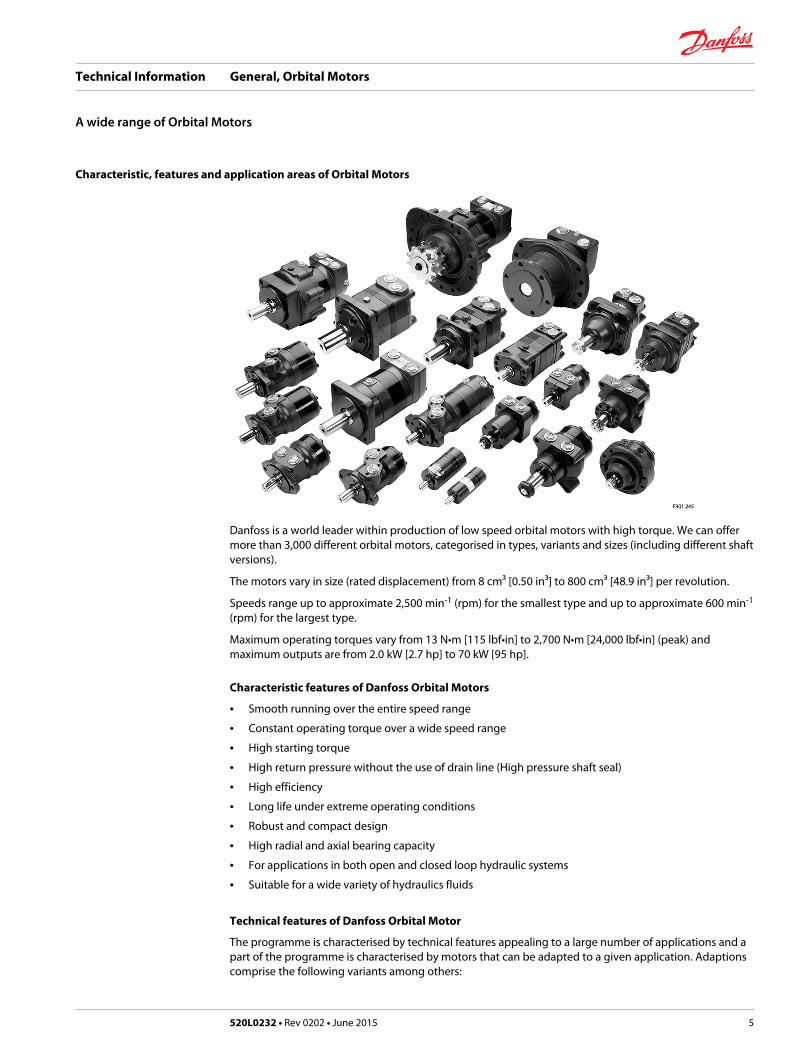
Danfoss is a world leader within production of low speed orbital motors with high torque. We can offermore than 3,000 different orbital motors, categorised in types, variants and sizes (including different shaftversions).
The motors vary in size (rated displacement) from 8 cm³ [0.50 in³] to 800 cm³ [48.9 in³] per revolution.
Speeds range up to approximate 2,500 min-1 (rpm) for the smallest type and up to approximate 600 min-1
(rpm) for the largest type.
Maximum operating torques vary from 13 N•m [115 lbf•in] to 2,700 N•m [24,000 lbf•in] (peak) andmaximum outputs are from 2.0 kW [2.7 hp] to 70 kW [95 hp].
Characteristic features of Danfoss Orbital Motors
• Smooth running over the entire speed range
• Constant operating torque over a wide speed range
• High starting torque
• High return pressure without the use of drain line (High pressure shaft seal)
• High efficiency
• Long life under extreme operating conditions
• Robust and compact design
• High radial and axial bearing capacity
• For applications in both open and closed loop hydraulic systems
• Suitable for a wide variety of hydraulics fluids
Technical features of Danfoss Orbital Motor
The programme is characterised by technical features appealing to a large number of applications and apart of the programme is characterised by motors that can be adapted to a given application. Adaptionscomprise the following variants among others:
Technical Information General, Orbital Motors
A wide range of Orbital Motors
520L0232 • Rev 0202 • June 2015 5
• Motors with corrosion resistant parts
• Wheel motors with recessed mounting flange
• OMP, OMR- motors with needle bearing
• OMR motor in low leakage version
• OMR motors in a super low leakage version
• Short motors without bearings
• Ultra short motors
• Motors with integrated positive holding brake
• Motors with integrated negative holding brake
• Motors with integrated flushing valve
• Motors with speed sensor
• Motors with tacho connection
• All motors are available with black finish paint
The Danfoss Orbital Motors are used in the following application areas:
• Construction equipment
• Agricultural equipment
• Material handling & Lifting equipment
• Forestry equipment
• Lawn and turf equipment
• Special purpose
• Machine tools and stationary equipment
• Marine equipment
Survey of literature with technical data on Danfoss Orbital Motors
Detailed data on all Danfoss Orbital Motors can be found in our motor catalogue, which is divided intomore individual subcatalogues:• General information on Danfoss Orbital Motors: function, use, selection of orbital motor, hydraulic
systems, etc.• Technical data on small motors: OML and OMM
• Technical data on medium sized motors: OMP, OMR, OMH
• Technical data on medium sized motors: DH and DS
• Technical data on medium sized motors: OMEW
• Technical data on medium sized motors: VMP
• Technical data on medium sized motors: VMR
• Technical data on large motors: OMS, OMT and OMV
• Technical data on large motors: TMK
• Technical data on large motors: TMT
• Technical data on large motors: TMTHW
• Technical data on large motors: TMVW
A general survey brochure on Danfoss Orbital Motors gives a quick motor reference based on power,torque, speed and capabilities.
Technical Information General, Orbital Motors
A wide range of Orbital Motors
6 520L0232 • Rev 0202 • June 2015
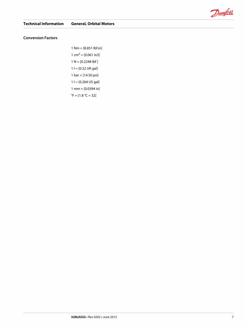
1 Nm = [8.851 lbf.in]
1 cm3 = [0.061 in3]
1 N = [0.2248 lbf ]
1 l = [0.22 UK gal]
1 bar = [14.50 psi]
1 l = [0.264 US gal]
1 mm = [0.0394 in]
°F = [1.8 °C + 32]
Technical Information General, Orbital Motors
Conversion Factors
520L0232 • Rev 0202 • June 2015 7
Operating Principle
Orbital motors convert hydraulic energy (pressure, oil flow) into mechanical energy (torque and speed).
Danfoss orbital motors are of fixed displacement high-torque design. For a given oil flow and givenpressure the displacement (size of motor) determines the speed and torque. For a given displacement(size of motor) the speed is determined by the oil flow rate and the torque is determined by the pressuredifferential.
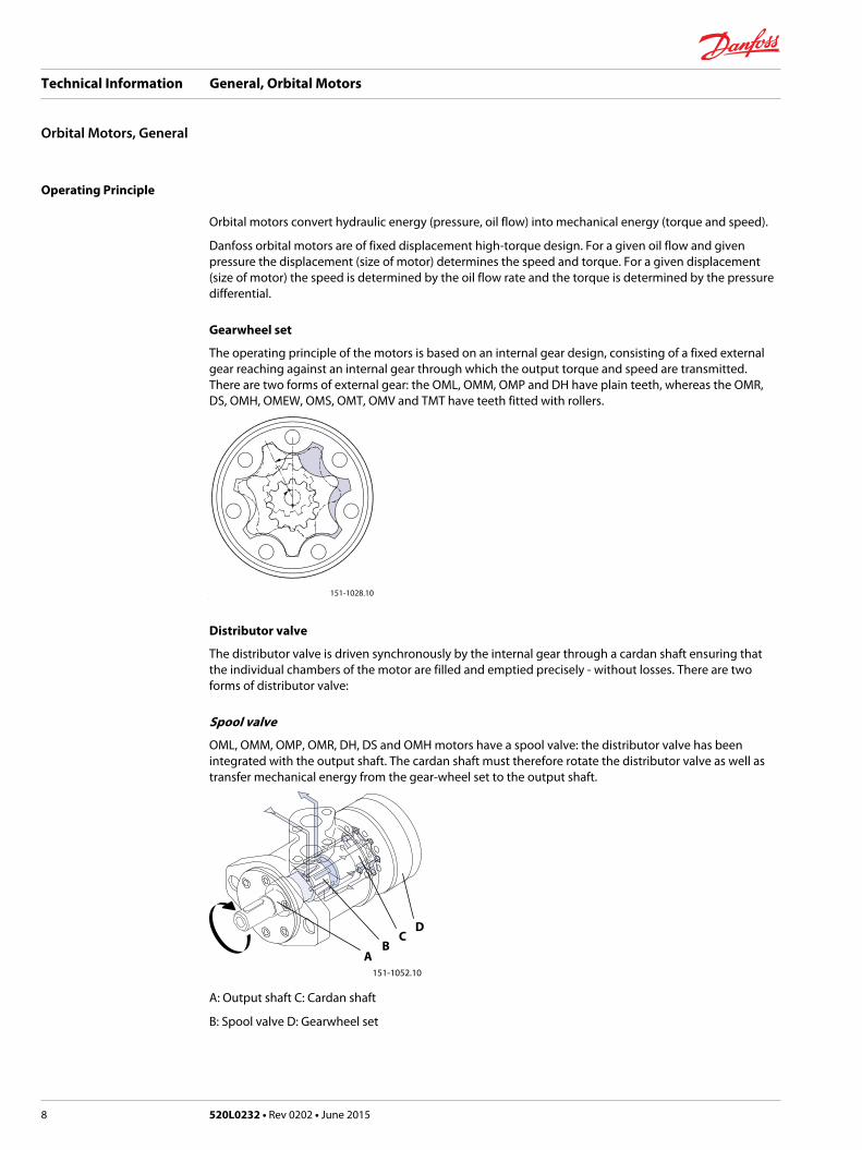
Gearwheel set
The operating principle of the motors is based on an internal gear design, consisting of a fixed externalgear reaching against an internal gear through which the output torque and speed are transmitted.There are two forms of external gear: the OML, OMM, OMP and DH have plain teeth, whereas the OMR,DS, OMH, OMEW, OMS, OMT, OMV and TMT have teeth fitted with rollers.
151-1028.10
Distributor valve
The distributor valve is driven synchronously by the internal gear through a cardan shaft ensuring thatthe individual chambers of the motor are filled and emptied precisely - without losses. There are twoforms of distributor valve:
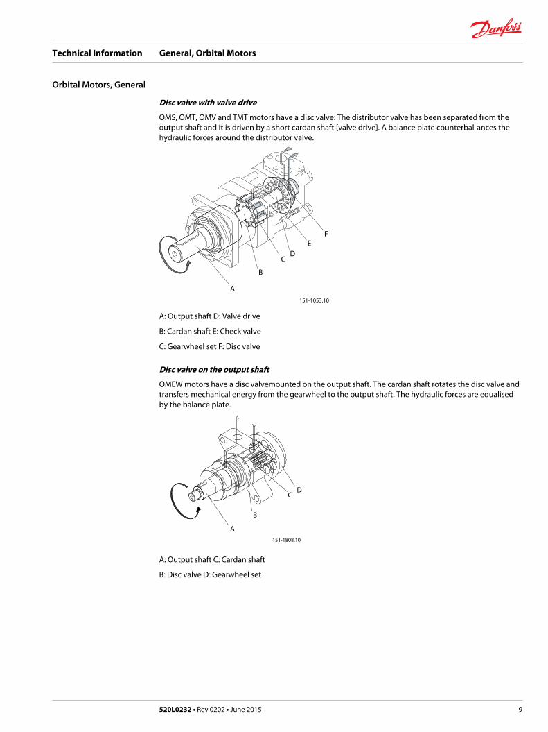
Spool valve
OML, OMM, OMP, OMR, DH, DS and OMH motors have a spool valve: the distributor valve has beenintegrated with the output shaft. The cardan shaft must therefore rotate the distributor valve as well astransfer mechanical energy from the gear-wheel set to the output shaft.
151-1052.10
AB
DC
A: Output shaft C: Cardan shaft
B: Spool valve D: Gearwheel set
Technical Information General, Orbital Motors
Orbital Motors, General
8 520L0232 • Rev 0202 • June 2015
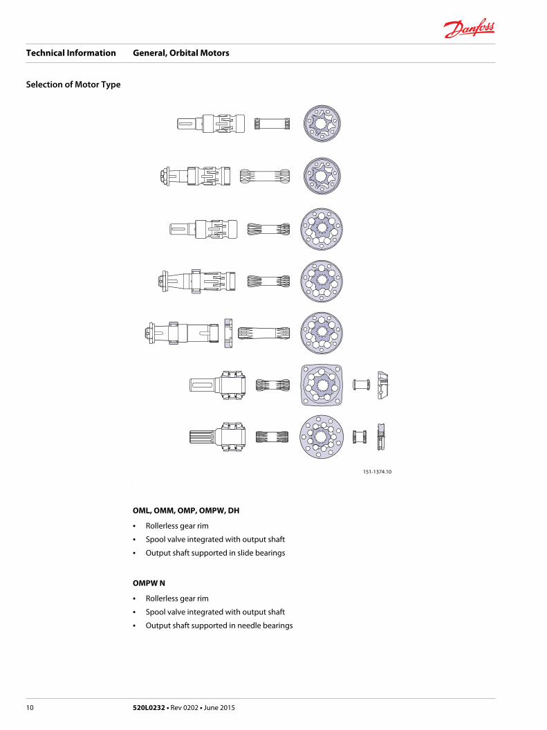
Disc valve with valve drive
OMS, OMT, OMV and TMT motors have a disc valve: The distributor valve has been separated from theoutput shaft and it is driven by a short cardan shaft [valve drive]. A balance plate counterbal-ances thehydraulic forces around the distributor valve.
151-1053.10
A
B
CD
EF
A: Output shaft D: Valve drive
B: Cardan shaft E: Check valve
C: Gearwheel set F: Disc valve
Disc valve on the output shaft
OMEW motors have a disc valvemounted on the output shaft. The cardan shaft rotates the disc valve andtransfers mechanical energy from the gearwheel to the output shaft. The hydraulic forces are equalisedby the balance plate.
151-1808.10
A
B
CD
A: Output shaft C: Cardan shaft
B: Disc valve D: Gearwheel set
Technical Information General, Orbital Motors
Orbital Motors, General
520L0232 • Rev 0202 • June 2015 9
151-1374.10
OML, OMM, OMP, OMPW, DH
• Rollerless gear rim
• Spool valve integrated with output shaft
• Output shaft supported in slide bearings
OMPW N
• Rollerless gear rim
• Spool valve integrated with output shaft
• Output shaft supported in needle bearings
Technical Information General, Orbital Motors
Selection of Motor Type
10 520L0232 • Rev 0202 • June 2015
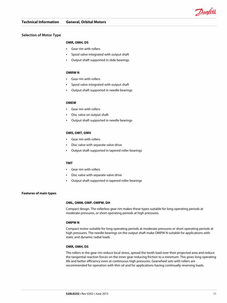
OMR, OMH, DS
• Gear rim with rollers
• Spool valve integrated with output shaft
• Output shaft supported in slide bearings
OMRW N
• Gear rim with rollers
• Spool valve integrated with output shaft
• Output shaft supported in needle bearings
OMEW
• Gear rim with rollers
• Disc valve on output shaft
• Output shaft supported in needle bearings
OMS, OMT, OMV
• Gear rim with rollers
• Disc valve with separate valve drive
• Output shaft supported in tapered roller bearings
TMT
• Gear rim with rollers
• Disc valve with separate valve drive
• Output shaft supported in tapered roller bearings
Features of main types
OML, OMM, OMP, OMPW, DH
Compact design. The rollerless gear rim makes these types suitable for long operating periods atmoderate pressures, or short operating periods at high pressures.
OMPW N
Compact motor suitable for long operating periods at moderate pressures or short operating periods athigh pressures. The needle bearings on the output shaft make OMPW N suitable for applications withstatic and dynamic radial loads.
OMR, OMH, DS
The rollers in the gear rim reduce local stress, spread the tooth load over their projected area and reducethe tangential reaction forces on the inner gear reducing friction to a minimum. This gives long operatinglife and better efficiency even at continuous high pressures. Gearwheel sets with rollers arerecommended for operation with thin oil and for applications having continually reversing loads.
Technical Information General, Orbital Motors
Selection of Motor Type
520L0232 • Rev 0202 • June 2015 11
OMRW N
Because of the rollers in the gear rim OMRW N is suitable for continuous operation under demandingoperating conditions: e.g. high pressures, thin oil, or frequent reversals. The needle bearings of theoutput shaft make OMRW N suitable for absorbing static and dynamic radial loads.
OMEW
OMEW motors have a disc valve mounted on the output shaft, i.e. hydraulic and mechanical losses arereduced to a minimum and the gearwheel set is fitted with rollers. OMEW is therefore ideal forcontinuous operation in demanding conditions. The output shaft runs in needle bearings capable ofabsorbing static and dynamic radial loads. OMEW motors are fitted with a high-pressure seal; thereforethe drain line can be omitted.
OMS, OMT, OMV
OMS, OMT, and OMV are suitable for continuous operation under rough operating conditions: e.g. highpressures, thin oil, or frequent reversals. The tapered roller bearings make the motors suitable forabsorbing static and dynamic radial loads. Besides the separately driven and hydraulically balanced discvalve, hydraulic and mechanical losses are reduced to a minimum. This gives the motors high efficiency -even at high pressures, and good starting characteristics.
TMT
The marked for hydraulic motors has developed generally increasing expectations of the motorperformance, and espacially of a higher pressure level. On some applications the present motor programno longer fulfils the marked demand. The TMT motors comply with these expectations providing thesame good characteristics as the OMS, OMT and OMV motors.
If the application requires very smooth running at low speeds the choice of OMS, OMT, OMV or TMT isrecommended.
Motor Variants
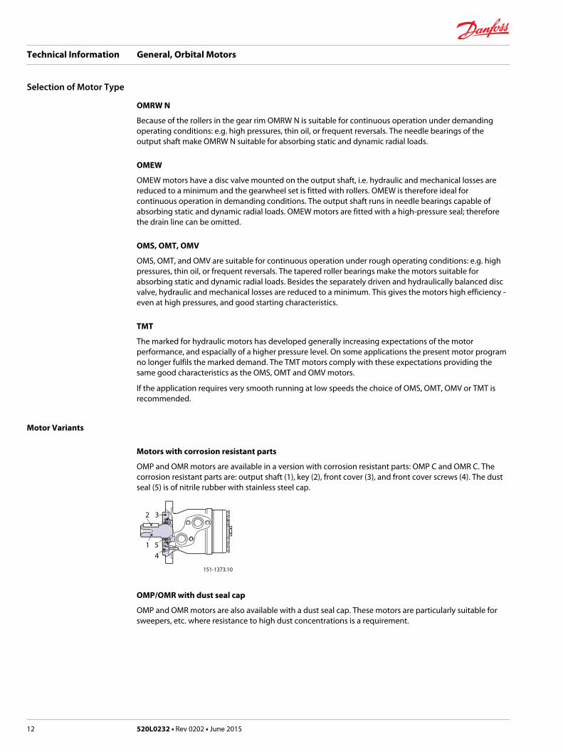
Motors with corrosion resistant parts
OMP and OMR motors are available in a version with corrosion resistant parts: OMP C and OMR C. Thecorrosion resistant parts are: output shaft (1), key (2), front cover (3), and front cover screws (4). The dustseal (5) is of nitrile rubber with stainless steel cap.
151-1373.10
2
1
3
54
OMP/OMR with dust seal cap
OMP and OMR motors are also available with a dust seal cap. These motors are particularly suitable forsweepers, etc. where resistance to high dust concentrations is a requirement.
Technical Information General, Orbital Motors
Selection of Motor Type
12 520L0232 • Rev 0202 • June 2015
151-1893.10
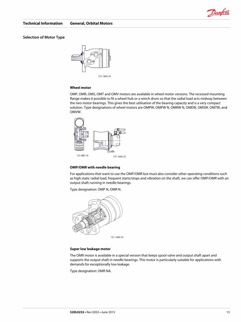
Wheel motor
OMP, OMR, OMS, OMT and OMV motors are available in wheel motor versions. The recessed mountingflange makes it possible to fit a wheel hub or a winch drum so that the radial load acts midway betweenthe two motor bearings. This gives the best utilisation of the bearing capacity and is a very compactsolution. Type designations of wheel motors are OMPW, OMPW N, OMRW N, OMEW, OMSW, OMTW, andOMVW.
151-887.10 151-1056.10
OMP/OMR with needle bearing
For applications that want to use the OMP/OMR but must also consider other operating conditions suchas high static radial load, frequent starts/stops and vibration on the shaft, we can offer OMP/OMR with anoutput shaft running in needle bearings.
Type designation: OMP N, OMR N.
151-1464.10
Super low leakage motor
The OMR motor is available in a special version that keeps spool valve and output shaft apart andsupports the output shaft in needle bearings. This motor is particularly suitable for applications withdemands for exceptionally low leakage.
Type designation: OMR NA.
Technical Information General, Orbital Motors
Selection of Motor Type
520L0232 • Rev 0202 • June 2015 13
151-1624.10
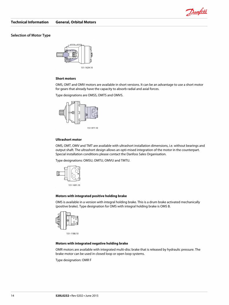
Short motors
OMS, OMT and OMV motors are available in short versions. It can be an advantage to use a short motorfor gears that already have the capacity to absorb radial and axial forces.
Type designations are OMSS, OMTS and OMVS.
151-977.10
Ultrashort motor
OMS, OMT, OMV and TMT are available with ultrashort installation dimensions, i.e. without bearings andoutput shaft. The ultrashort design allows an opti-mised integration of the motor in the counterpart.Special installation conditions please contact the Danfoss Sales Organisation.
Type designations: OMSU, OMTU, OMVU and TMTU.
151-1691.10
Motors with integrated positive holding brake
OMS is available in a version with integral holding brake. This is a drum brake activated mechanically(positive brake). Type designation for OMS with integral holding brake is OMS B.
151-1188.10
Motors with integrated negative holding brake
OMR motors are available with integrated multi-disc brake that is released by hydraulic pressure. Thebrake motor can be used in closed loop or open loop systems.
Type designation: OMR F
Technical Information General, Orbital Motors
Selection of Motor Type
14 520L0232 • Rev 0202 • June 2015
151-1797.10
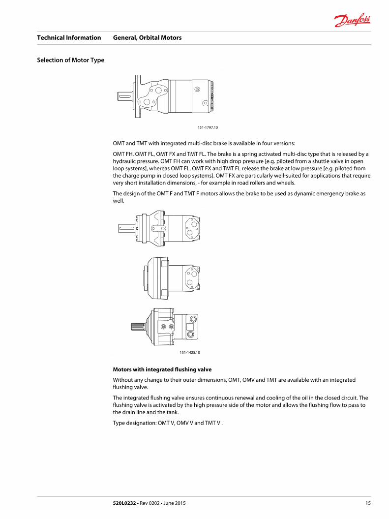
OMT and TMT with integrated multi-disc brake is available in four versions:
OMT FH, OMT FL, OMT FX and TMT FL. The brake is a spring activated multi-disc type that is released by ahydraulic pressure. OMT FH can work with high drop pressure [e.g. piloted from a shuttle valve in openloop systems], whereas OMT FL, OMT FX and TMT FL release the brake at low pressure [e.g. piloted fromthe charge pump in closed loop systems]. OMT FX are particularly well-suited for applications that requirevery short installation dimensions, - for example in road rollers and wheels.
The design of the OMT F and TMT F motors allows the brake to be used as dynamic emergency brake aswell.
151-1425.10
Motors with integrated flushing valve
Without any change to their outer dimensions, OMT, OMV and TMT are available with an integratedflushing valve.
The integrated flushing valve ensures continuous renewal and cooling of the oil in the closed circuit. Theflushing valve is activated by the high pressure side of the motor and allows the flushing flow to pass tothe drain line and the tank.
Type designation: OMT V, OMV V and TMT V .
Technical Information General, Orbital Motors
Selection of Motor Type
520L0232 • Rev 0202 • June 2015 15
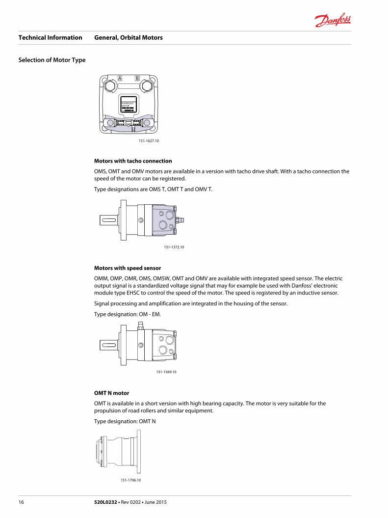
151-1627.10
A B
Motors with tacho connection
OMS, OMT and OMV motors are available in a version with tacho drive shaft. With a tacho connection thespeed of the motor can be registered.
Type designations are OMS T, OMT T and OMV T.
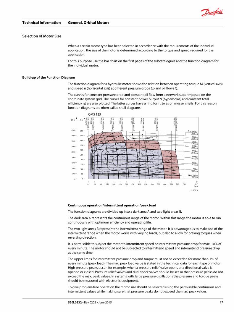
151-1372.10
Motors with speed sensor
OMM, OMP, OMR, OMS, OMSW, OMT and OMV are available with integrated speed sensor. The electricoutput signal is a standardized voltage signal that may for example be used with Danfoss' electronicmodule type EHSC to control the speed of the motor. The speed is registered by an inductive sensor.
Signal processing and amplification are integrated in the housing of the sensor.
Type designation: OM - EM.
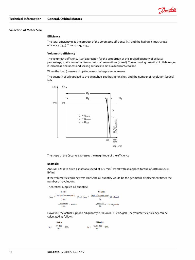
151-1569.10
OMT N motor
OMT is available in a short version with high bearing capacity. The motor is very suitable for thepropulsion of road rollers and similar equipment.
Type designation: OMT N
151-1796.10
Technical Information General, Orbital Motors
Selection of Motor Type
16 520L0232 • Rev 0202 • June 2015
When a certain motor type has been selected in accordance with the requirements of the individualapplication, the size of the motor is determined according to the torque and speed required for theapplication.
For this purpose use the bar chart on the first pages of the subcatalogues and the function diagram forthe individual motor.
Build-up of the Function Diagram
The function diagram for a hydraulic motor shows the relation between operating torque M (vertical axis)and speed n (horizontal axis) at different pressure drops ∆p and oil flows Q.
The curves for constant pressure drop and constant oil flow form a network superimposed on thecoordinate system grid. The curves for constant power output N (hyperbolas] and constant totalefficiency ηt are also plotted. The latter curves have a ring form, to as on mussel shells. For this reasonfunction diagrams are often called shell diagrams.
OMS 125lbf• in Nm
4500
4000
3500
3000
2500
2000
1500
1000
500
0
500
450
400
350
300
250
200
150
100
50
0
0 50 100 150 200 250 300 350 400 450 500 550 600 650 700 750
151-903.10
min-1
(rpm)
10 l/
min
[2.6
US
gal/m
in]
Q=5
l/m
in[1
.3 U
S ga
l/min
]
Q=9
0 l/m
in[2
3.8
US
gal/m
in]
75 l/
min
[19.
8 U
S ga
l/min
]
20 l/
min
[5.3
US
gal/m
in]
40 l/
min
[10.
6 U
S ga
l/min
]
30 l/
min
[7.9
US
gal/m
in]
50 l/
min
[13.
2 U
S ga
l/min
]
60 l/
min
[15.
9 U
S ga
l/min
]
210 bar
∆ p= 35 bar
3050 psi175 bar
2540 psi
225 bar3260 psi
250 bar3630 psi
105 bar1520 psi
∆ p=275 bar3990 psi
510 psi
2030 psi140 bar
1020 psi70 bar
N=1kW
6kW
N=21kW
75%70%
12hp 18hp15hp
6hp
1hp
η t =85%
80%
83%
η t =60%
9hp
15kW12kW
21hp 18kW
3kW
9kW
3hp
Continuous operation/intermittent operation/peak load
The function diagrams are divided up into a dark area A and two light areas B.
The dark area A represents the continuous range of the motor. Within this range the motor is able to runcontinuously with optimum efficiency and operating life.
The two light areas B represent the intermittent range of the motor. It is advantageous to make use of theintermittent range when the motor works with varying loads, but also to allow for braking torques whenreversing direction.
It is permissible to subject the motor to intermittent speed or intermittent pressure drop for max. 10% ofevery minute. The motor should not be subjected to intermittend speed and intermitend pressure dropat the same time.
The upper limits for intermittent pressure drop and torque must not be exceeded for more than 1% ofevery minute (peak load). The max. peak load value is stated in the technical data for each type of motor.High pressure peaks occur, for example, when a pressure relief valve opens or a directional valve isopened or closed. Pressure relief valves and dual shock valves should be set so that pressure peaks do notexceed the max. peak values. In systems with large pressure oscillations the pressure and torque peaksshould be measured with electronic equipment.
To give problem-free operation the motor size should be selected using the permissible continuous andintermittent values while making sure that pressure peaks do not exceed the max. peak values.
Technical Information General, Orbital Motors
Selection of Motor Size
520L0232 • Rev 0202 • June 2015 17
Efficiency
The total efficiency ηt is the product of the volumetric efficiency (ηv) and the hydraulic-mechanicalefficiency (ηhm). Thus ηt = ηv x ηhm.
Volumetric efficiency
The volumetric efficiency is an expression for the proportion of the applied quantity of oil [as apercentage] that is converted to output shaft revolutions (speed). The remaining quantity of oil (leakage)is led across clearances and sealing surfaces to act as a lubricant/coolant.
When the load (pressure drop) increases, leakage also increases.
The quantity of oil supplied to the gearwheel set thus diminishes, and the number of revolution (speed)falls.
2745 310
Nmin•lbs
151-247.10
50 l/
min
[13.
2 U
S ga
l/min
]
375 min-1
(rpm)
ηV
Q1
Q2 Q3
Q1 = QtotalQ2 = Qtheor*Q3 = Qleak
The slope of the Q-curve expresses the magnitude of the efficiency
Example
An OMS 125 is to drive a shaft at a speed of 375 min-1 (rpm) with an applied torque of 310 Nm [2745lbf•in].
If the volumetric efficiency was 100% the oil quantity would be the geometric displacement times thenumber of revolutions.
Theoretical supplied oil quantity:
However, the actual supplied oil quantity is 50 l/min [13.2 US gal]. The volumetric efficiency can becalculated as follows:
Technical Information General, Orbital Motors
Selection of Motor Size
18 520L0232 • Rev 0202 • June 2015
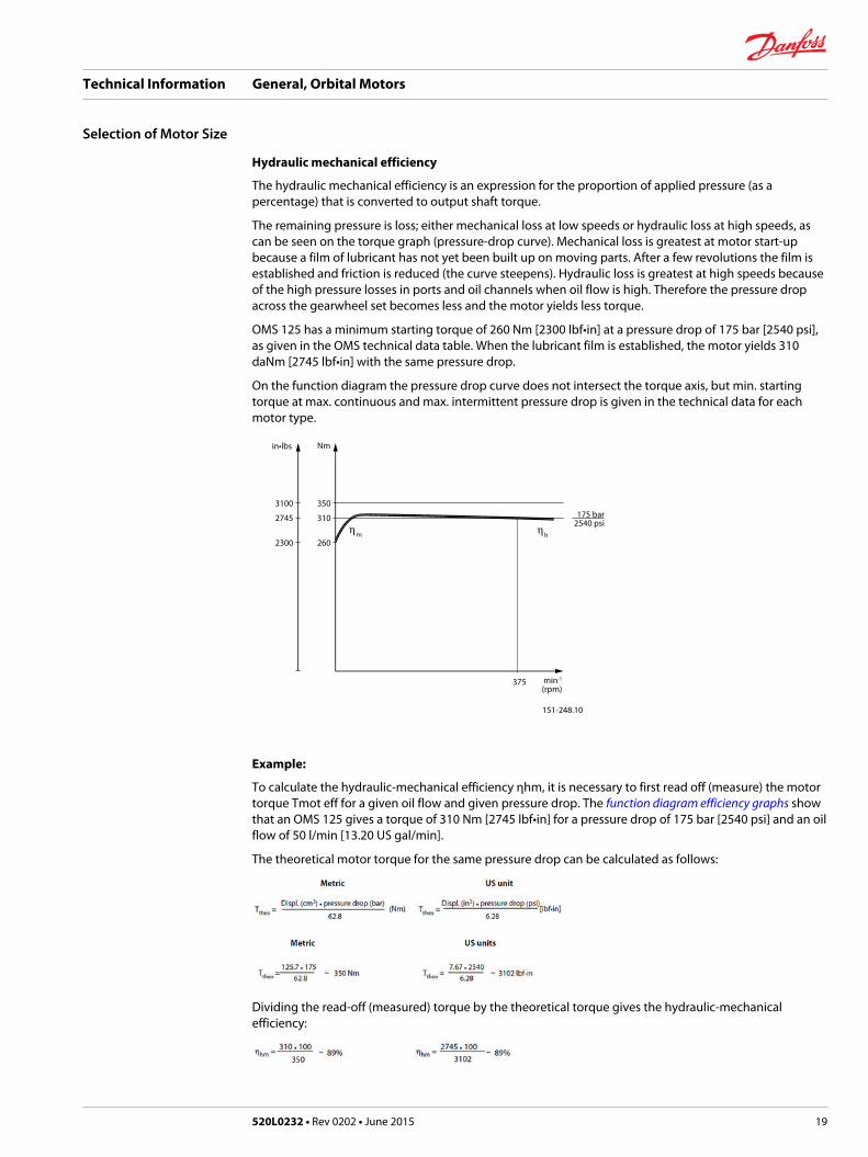
Hydraulic mechanical efficiency
The hydraulic mechanical efficiency is an expression for the proportion of applied pressure (as apercentage) that is converted to output shaft torque.
The remaining pressure is loss; either mechanical loss at low speeds or hydraulic loss at high speeds, ascan be seen on the torque graph (pressure-drop curve). Mechanical loss is greatest at motor start-upbecause a film of lubricant has not yet been built up on moving parts. After a few revolutions the film isestablished and friction is reduced (the curve steepens). Hydraulic loss is greatest at high speeds becauseof the high pressure losses in ports and oil channels when oil flow is high. Therefore the pressure dropacross the gearwheel set becomes less and the motor yields less torque.
OMS 125 has a minimum starting torque of 260 Nm [2300 lbf•in] at a pressure drop of 175 bar [2540 psi],as given in the OMS technical data table. When the lubricant film is established, the motor yields 310daNm [2745 lbf•in] with the same pressure drop.
On the function diagram the pressure drop curve does not intersect the torque axis, but min. startingtorque at max. continuous and max. intermittent pressure drop is given in the technical data for eachmotor type.
3100
2745
2300
350
310
260
Nmin•lbs
175 bar2540 psi
151-248.10
375 min-1
(rpm)
ηhηm
Example:
To calculate the hydraulic-mechanical efficiency ηhm, it is necessary to first read off (measure) the motortorque Tmot eff for a given oil flow and given pressure drop. The function diagram efficiency graphs showthat an OMS 125 gives a torque of 310 Nm [2745 lbf•in] for a pressure drop of 175 bar [2540 psi] and an oilflow of 50 l/min [13.20 US gal/min].
The theoretical motor torque for the same pressure drop can be calculated as follows:
Dividing the read-off (measured) torque by the theoretical torque gives the hydraulic-mechanicalefficiency:
Technical Information General, Orbital Motors
Selection of Motor Size
520L0232 • Rev 0202 • June 2015 19
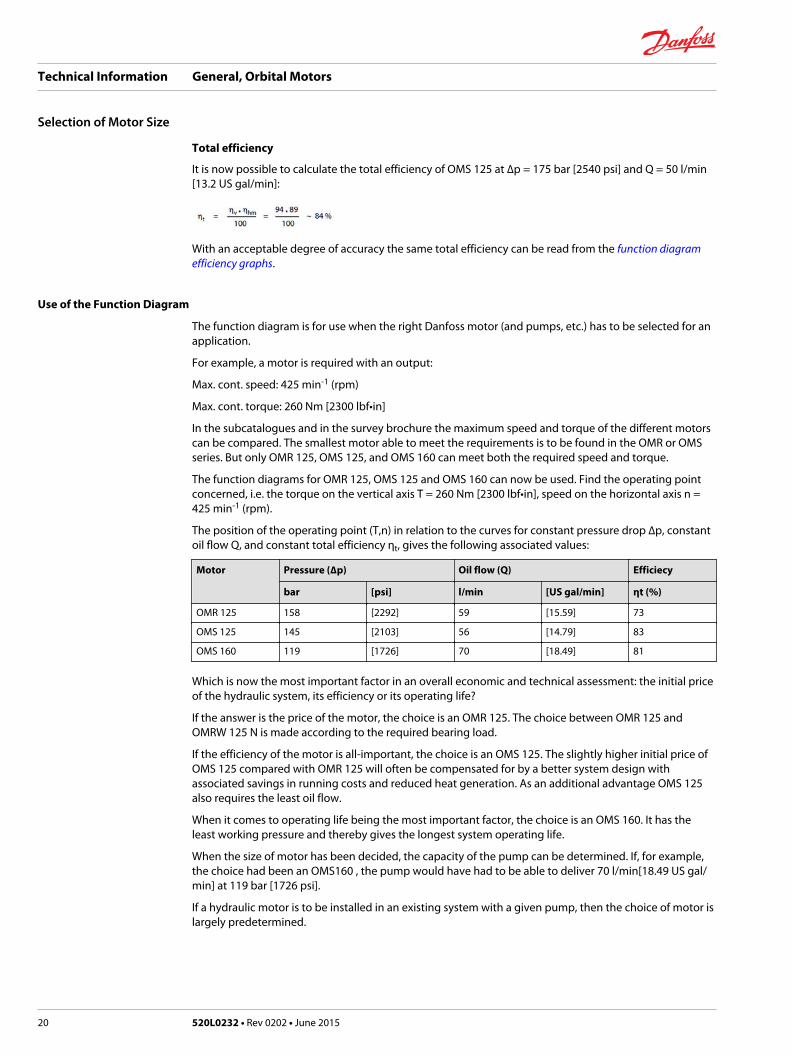
Total efficiency
It is now possible to calculate the total efficiency of OMS 125 at ∆p = 175 bar [2540 psi] and Q = 50 l/min[13.2 US gal/min]:
With an acceptable degree of accuracy the same total efficiency can be read from the function diagramefficiency graphs.
Use of the Function Diagram
The function diagram is for use when the right Danfoss motor (and pumps, etc.) has to be selected for anapplication.
For example, a motor is required with an output:
Max. cont. speed: 425 min-1 (rpm)
Max. cont. torque: 260 Nm [2300 lbf•in]
In the subcatalogues and in the survey brochure the maximum speed and torque of the different motorscan be compared. The smallest motor able to meet the requirements is to be found in the OMR or OMSseries. But only OMR 125, OMS 125, and OMS 160 can meet both the required speed and torque.
The function diagrams for OMR 125, OMS 125 and OMS 160 can now be used. Find the operating pointconcerned, i.e. the torque on the vertical axis T = 260 Nm [2300 lbf•in], speed on the horizontal axis n =425 min-1 (rpm).
The position of the operating point (T,n) in relation to the curves for constant pressure drop ∆p, constantoil flow Q, and constant total efficiency ηt, gives the following associated values:
Motor Pressure (∆p) Oil flow (Q) Efficiecy
bar [psi] l/min [US gal/min] ηt (%)
OMR 125 158 [2292] 59 [15.59] 73
OMS 125 145 [2103] 56 [14.79] 83
OMS 160 119 [1726] 70 [18.49] 81
Which is now the most important factor in an overall economic and technical assessment: the initial priceof the hydraulic system, its efficiency or its operating life?
If the answer is the price of the motor, the choice is an OMR 125. The choice between OMR 125 andOMRW 125 N is made according to the required bearing load.
If the efficiency of the motor is all-important, the choice is an OMS 125. The slightly higher initial price ofOMS 125 compared with OMR 125 will often be compensated for by a better system design withassociated savings in running costs and reduced heat generation. As an additional advantage OMS 125also requires the least oil flow.
When it comes to operating life being the most important factor, the choice is an OMS 160. It has theleast working pressure and thereby gives the longest system operating life.
When the size of motor has been decided, the capacity of the pump can be determined. If, for example,the choice had been an OMS160 , the pump would have had to be able to deliver 70 l/min[18.49 US gal/min] at 119 bar [1726 psi].
If a hydraulic motor is to be installed in an existing system with a given pump, then the choice of motor islargely predetermined.
Technical Information General, Orbital Motors
Selection of Motor Size
20 520L0232 • Rev 0202 • June 2015
Minimum speed
At very low speeds, the motors may run less smoothly. In borderline cases a motor of the desired typeshould be tested under the required operating conditions in the system concerned before finallyselecting the motor size and type.
To obtain smooth running at very low speed the motor leakage must be constant. Therefore it isrecommended that a motor with disc valve (OMS, OMT, OMV or TMT) be chosen, but avoid choosingmotors with the smaller displacements. The best results are achieved with a constant load, a returnpressure of 3-5 bar [45-70 psi] and an oil viscosity of min. 35 mm2/s [164 SUS].
Technical Information General, Orbital Motors
Selection of Motor Size
520L0232 • Rev 0202 • June 2015 21
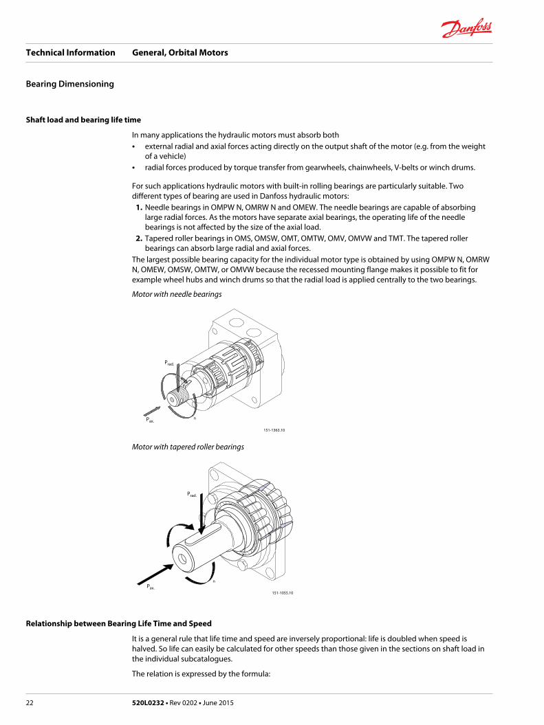
Shaft load and bearing life time
In many applications the hydraulic motors must absorb both• external radial and axial forces acting directly on the output shaft of the motor (e.g. from the weight
of a vehicle)• radial forces produced by torque transfer from gearwheels, chainwheels, V-belts or winch drums.
For such applications hydraulic motors with built-in rolling bearings are particularly suitable. Twodifferent types of bearing are used in Danfoss hydraulic motors:
1. Needle bearings in OMPW N, OMRW N and OMEW. The needle bearings are capable of absorbinglarge radial forces. As the motors have separate axial bearings, the operating life of the needlebearings is not affected by the size of the axial load.
2. Tapered roller bearings in OMS, OMSW, OMT, OMTW, OMV, OMVW and TMT. The tapered rollerbearings can absorb large radial and axial forces.
The largest possible bearing capacity for the individual motor type is obtained by using OMPW N, OMRWN, OMEW, OMSW, OMTW, or OMVW because the recessed mounting flange makes it possible to fit forexample wheel hubs and winch drums so that the radial load is applied centrally to the two bearings.
Motor with needle bearings
151-1363.10
nPax.
Prad.
Motor with tapered roller bearings
151-1055.10
nPax.
Prad.
Relationship between Bearing Life Time and Speed
It is a general rule that life time and speed are inversely proportional: life is doubled when speed ishalved. So life can easily be calculated for other speeds than those given in the sections on shaft load inthe individual subcatalogues.
The relation is expressed by the formula:
Technical Information General, Orbital Motors
Bearing Dimensioning
22 520L0232 • Rev 0202 • June 2015
Lnew = Lref x (nref / nnew)
where Lnew is the life time at speed nnew, and Lref and nref are the data for the given motor type found inthe subcatalogue.
Relationship between Shaft Load and Bearing Life Time
Lower shaft loads result in longer life time of the bearings. The exact relationship is shown by thefollowing formula:
Lnew is the bearing life at a shaft load of Pnew, and Lref and nref are data from the subcatalogue.
• The formula applies to OMPW N, OMEW and OMRW N regardless of the relation between the axialand radial loads.
• With the other motors the formula only applies if there is a constant relation between the axial andradial loads.
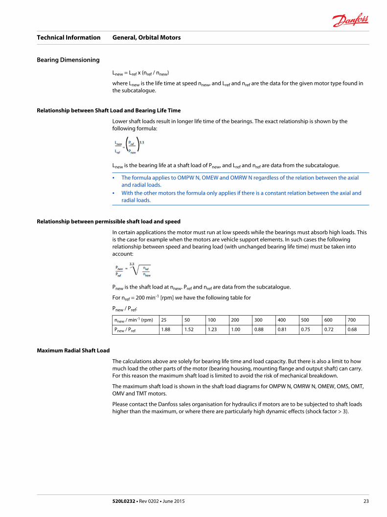
Relationship between permissible shaft load and speed
In certain applications the motor must run at low speeds while the bearings must absorb high loads. Thisis the case for example when the motors are vehicle support elements. In such cases the followingrelationship between speed and bearing load (with unchanged bearing life time) must be taken intoaccount:
Pnew is the shaft load at nnew. Pref and nref are data from the subcatalogue.
For nref = 200 min-1 [rpm] we have the following table for
Pnew / Pref:
nnew / min-1 (rpm) 25 50 100 200 300 400 500 600 700
Pnew / Pref 1.88 1.52 1.23 1.00 0.88 0.81 0.75 0.72 0.68
Maximum Radial Shaft Load
The calculations above are solely for bearing life time and load capacity. But there is also a limit to howmuch load the other parts of the motor (bearing housing, mounting flange and output shaft) can carry.For this reason the maximum shaft load is limited to avoid the risk of mechanical breakdown.
The maximum shaft load is shown in the shaft load diagrams for OMPW N, OMRW N, OMEW, OMS, OMT,OMV and TMT motors.
Please contact the Danfoss sales organisation for hydraulics if motors are to be subjected to shaft loadshigher than the maximum, or where there are particularly high dynamic effects (shock factor > 3).
Technical Information General, Orbital Motors
Bearing Dimensioning
520L0232 • Rev 0202 • June 2015 23
Max. Pressure on the Shaft Seal
Danfoss hydraulic motors can be supplied fitted with one of three different shaft seals:
Standard shaft seal (NBR)
The standard shaft seal in Danfoss hydraulic motors has a long operating life and even under extremeconditions retains its sealing capability. With optimal lip design, the shaft seal withstands both highpressures and high speeds.
High-pressure shaft seal (NBR)
The high-pressure shaft seal (HPS) is a development of our standard shaft seal and the integrated backingring makes an external drain line superfluous in most operating conditions.
Viton shaft seal (FPM)
If a synthetic fluid is to be used in our hydraulic motors we recommend a Viton shaft seal.
Characteristics of sealing materials
Material Temperature ˚C [˚F] Remarks
NBR -30 to + 100[-22 to 212]
Swells up on contact with most syntetic fluidsCan be used with Emulsions and Mineral oils
FPM -30 to + 150[-22 to 302]
Ideal for mineral oil, synthetic fluids andemulsions
All Danfoss motors, except the OMEW, are 3-cham-ber type of motors, i.e. this type og motor isolates thehigh pressure from the case, which allows the use of an external drain when return line pressure isexcessive. These motors are offered with the following option:
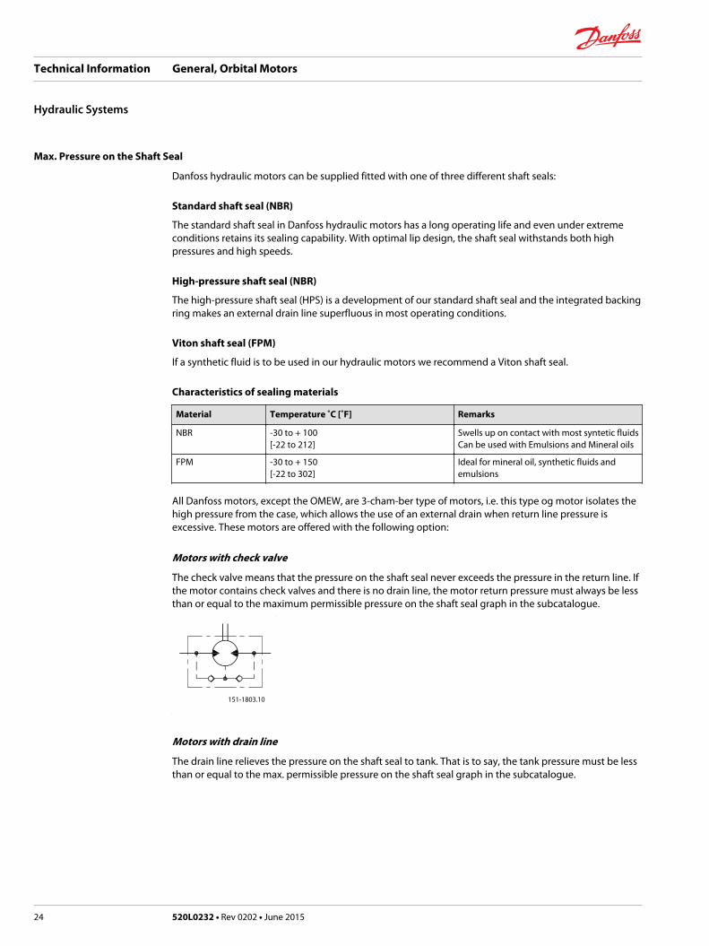
Motors with check valve
The check valve means that the pressure on the shaft seal never exceeds the pressure in the return line. Ifthe motor contains check valves and there is no drain line, the motor return pressure must always be lessthan or equal to the maximum permissible pressure on the shaft seal graph in the subcatalogue.
151-1803.10
Motors with drain line
The drain line relieves the pressure on the shaft seal to tank. That is to say, the tank pressure must be lessthan or equal to the max. permissible pressure on the shaft seal graph in the subcatalogue.
Technical Information General, Orbital Motors
Hydraulic Systems
24 520L0232 • Rev 0202 • June 2015
151-1807.10
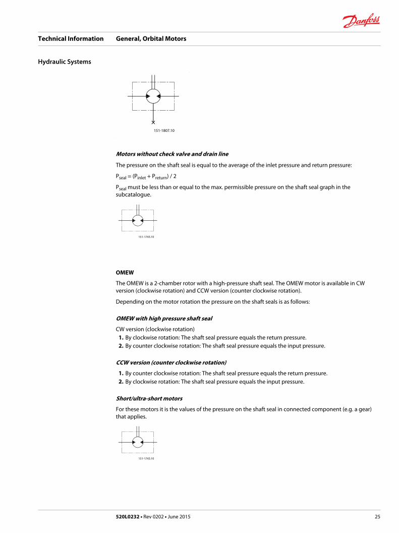
Motors without check valve and drain line
The pressure on the shaft seal is equal to the average of the inlet pressure and return pressure:
Pseal = (Pinlet + Preturn) / 2
Pseal must be less than or equal to the max. permissible pressure on the shaft seal graph in thesubcatalogue.
151-1743.10
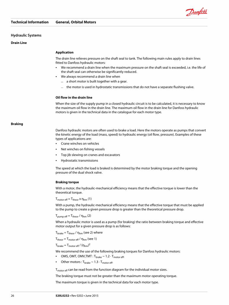
OMEW
The OMEW is a 2-chamber rotor with a high-pressure shaft seal. The OMEW motor is available in CWversion (clockwise rotation) and CCW version (counter clockwise rotation).
Depending on the motor rotation the pressure on the shaft seals is as follows:
OMEW with high pressure shaft seal
CW version (clockwise rotation)1. By clockwise rotation: The shaft seal pressure equals the return pressure.2. By counter clockwise rotation: The shaft seal pressure equals the input pressure.
CCW version (counter clockwise rotation)
1. By counter clockwise rotation: The shaft seal pressure equals the return pressure.2. By clockwise rotation: The shaft seal pressure equals the input pressure.
Short/ultra-short motors
For these motors it is the values of the pressure on the shaft seal in connected component (e.g. a gear)that applies.
151-1743.10
Technical Information General, Orbital Motors
Hydraulic Systems
520L0232 • Rev 0202 • June 2015 25
Drain Line
Application
The drain line relieves pressure on the shaft seal to tank. The following main rules apply to drain linesfitted to Danfoss hydraulic motors:• We recommend a drain line when the maximum pressure on the shaft seal is exceeded, i.e. the life of
the shaft seal can otherwise be significantly reduced.• We always recommend a drain line when
‒ a short motor is built together with a gear.
‒ the motor is used in hydrostatic transmissions that do not have a separate flushing valve.
Oil flow in the drain line
When the size of the supply pump in a closed hydraulic circuit is to be calculated, it is necessary to knowthe maximum oil flow in the drain line. The maximum oil flow in the drain line for Danfoss hydraulicmotors is given in the technical data in the catalogue for each motor type.
Braking
Danfoss hydraulic motors are often used to brake a load. Here the motors operate as pumps that convertthe kinetic energy of the load (mass, speed) to hydraulic energy (oil flow, pressure). Examples of thesetypes of applications are:• Crane winches on vehicles
• Net winches on fishing vessels
• Top jib slewing on cranes and excavators
• Hydrostatic transmissions
The speed at which the load is braked is determined by the motor braking torque and the openingpressure of the dual shock valve.
Braking torque
With a motor, the hydraulic-mechanical efficiency means that the effective torque is lower than thetheoretical torque.
Tmotor eff = Ttheor x ηhm (1)
With a pump, the hydraulic-mechanical efficiency means that the effective torque that must be appliedto the pump to create a given pressure drop is greater than the theoretical pressure drop.
Tpump eff = Ttheor / ηhm (2)
When a hydraulic motor is used as a pump (for braking) the ratio between braking torque and effectivemotor output for a given pressure drop is as follows:
Tbrake = Ttheor / ηhm (see 2) where
Ttheor = Tmotor eff / ηhm (see 1)
Tbrake = Tmotor eff / (ηhm)2
We recommend the use of the following braking torques for Danfoss hydraulic motors:• OMS, OMT, OMV,TMT : Tbrake ~ 1.2 · Tmotor eff.
• Other motors : Tbrake ~ 1.3 · Tmotor eff.
Tmotor eff can be read from the function diagram for the individual motor sizes.
The braking torque must not be greater than the maximum motor operating torque.
The maximum torque is given in the technical data for each motor type.
Technical Information General, Orbital Motors
Hydraulic Systems
26 520L0232 • Rev 0202 • June 2015
Opening pressure for the dual shock valve
The braking torque can be regulated by setting the opening pressure of the dual shock valve. Theopening pressure should be set at max. oil flow, in that a 20-30% increase in opening pressure can beexpected when the oil flow is changed from minimum to maximum.
To avoid excessive pressure peaks, the dual shock valve should be rapid acting and be installed as closeto the hydraulic motor as possible.
Replenishment
When Danfoss hydraulic motors are used to brake a load, effective replenishment is necessary.Inadequate replenishment can give rise to:• cavitation in the gearwheel set
• insufficient braking capacity
There must therefore be positive charge pressure in the motor "suction" port.
The charge pressure (ps) must therefore be greater than the pressure drop in the motor oil channelsfeeding the gearwheel set.
The pressure drop in the oil channels depends on the motor type, oil flow and oil viscosity. The pressuredrop graphs for each motor type are given in the respective catalogues.
The supply pressure should constitute half the pressure drop (pd) given on the graph:
ps = pd / 2
The charge pressure is always measured at the motor "suction" port.
In closed circuits the supply pressure will always be positive when the system is fitted with a chargepump (ps ~ 10-15 bar [145-217 psi]).
In open systems where the hydraulic motor drives a load with high inertia, it is necessary to establishreplenishment as shown in fig. 1.
The opening pressure of the check valve must be greater than the sum of the charge pressure (ps) andthe pressure drop between check valve and motor "suction" port.
Technical Information General, Orbital Motors
Hydraulic Systems
520L0232 • Rev 0202 • June 2015 27
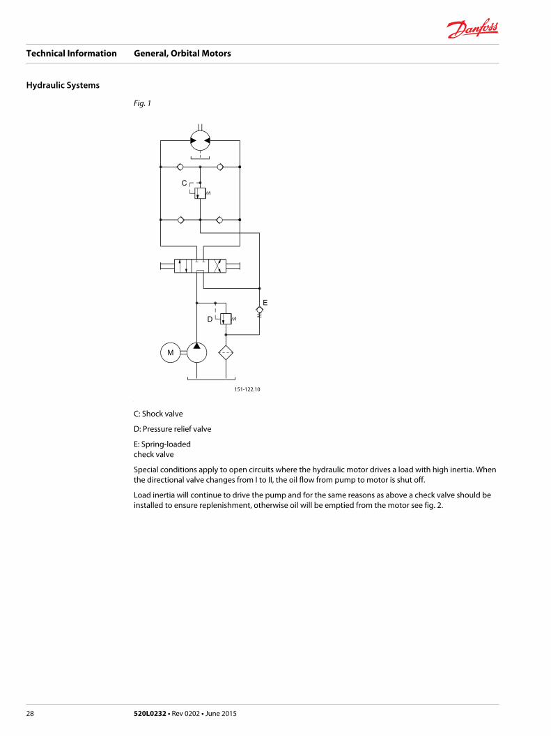
Fig. 1
151-122.10
C: Shock valve
D: Pressure relief valve
E: Spring-loaded check valve
Special conditions apply to open circuits where the hydraulic motor drives a load with high inertia. Whenthe directional valve changes from I to II, the oil flow from pump to motor is shut off.
Load inertia will continue to drive the pump and for the same reasons as above a check valve should beinstalled to ensure replenishment, otherwise oil will be emptied from the motor see fig. 2.
Technical Information General, Orbital Motors
Hydraulic Systems
28 520L0232 • Rev 0202 • June 2015
151-1142.10
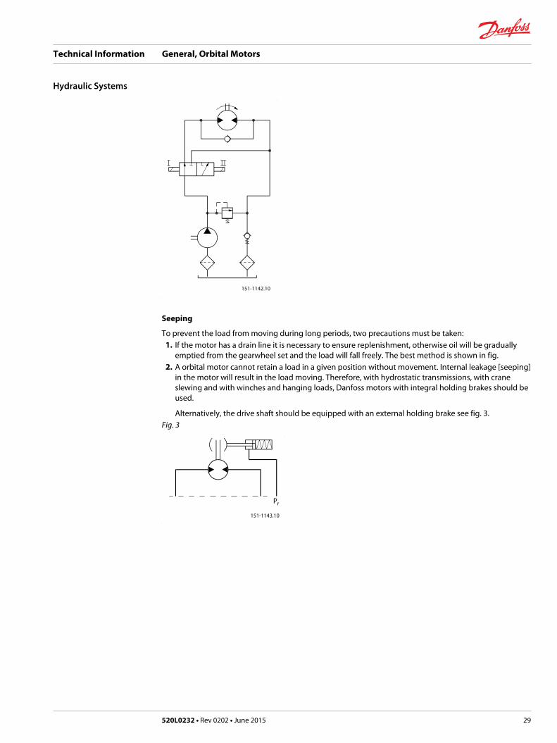
Seeping
To prevent the load from moving during long periods, two precautions must be taken:1. If the motor has a drain line it is necessary to ensure replenishment, otherwise oil will be gradually
emptied from the gearwheel set and the load will fall freely. The best method is shown in fig.2. A orbital motor cannot retain a load in a given position without movement. Internal leakage [seeping]
in the motor will result in the load moving. Therefore, with hydrostatic transmissions, with craneslewing and with winches and hanging loads, Danfoss motors with integral holding brakes should beused.
Alternatively, the drive shaft should be equipped with an external holding brake see fig. 3.Fig. 3
151-1143.10
Pr
Technical Information General, Orbital Motors
Hydraulic Systems
520L0232 • Rev 0202 • June 2015 29
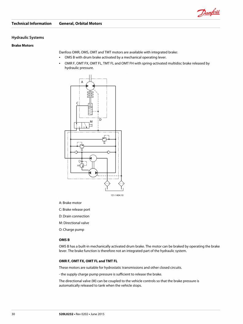
Brake Motors
Danfoss OMR, OMS, OMT and TMT motors are available with integrated brake:• OMS B with drum brake activated by a mechanical operating lever.
• OMR F, OMT FX, OMT FL, TMT FL and OMT FH with spring-activated multidisc brake released byhydraulic pressure.
151-1404.10
A
C
MD
A: Brake motor
C: Brake release port
D: Drain connection
M: Directional valve
O: Charge pump
OMS B
OMS B has a built-in mechanically activated drum brake. The motor can be braked by operating the brakelever. The brake function is therefore not an integrated part of the hydraulic system.
OMR F, OMT FX, OMT FL and TMT FL
These motors are suitable for hydrostatic transmissions and other closed circuits.
- the supply charge pump pressure is sufficient to release the brake.
The directional valve (M) can be coupled to the vehicle controls so that the brake pressure isautomatically released to tank when the vehicle stops.
Technical Information General, Orbital Motors
Hydraulic Systems
30 520L0232 • Rev 0202 • June 2015
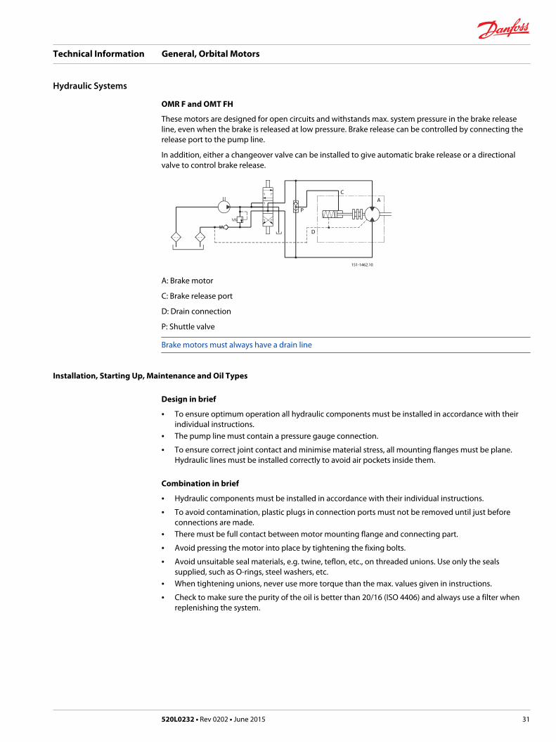
OMR F and OMT FH
These motors are designed for open circuits and withstands max. system pressure in the brake releaseline, even when the brake is released at low pressure. Brake release can be controlled by connecting therelease port to the pump line.
In addition, either a changeover valve can be installed to give automatic brake release or a directionalvalve to control brake release.
151-1462.10
AC
P
D
A: Brake motor
C: Brake release port
D: Drain connection
P: Shuttle valve
Brake motors must always have a drain line
Installation, Starting Up, Maintenance and Oil Types
Design in brief
• To ensure optimum operation all hydraulic components must be installed in accordance with theirindividual instructions.
• The pump line must contain a pressure gauge connection.
• To ensure correct joint contact and minimise material stress, all mounting flanges must be plane.Hydraulic lines must be installed correctly to avoid air pockets inside them.
Combination in brief
• Hydraulic components must be installed in accordance with their individual instructions.
• To avoid contamination, plastic plugs in connection ports must not be removed until just beforeconnections are made.
• There must be full contact between motor mounting flange and connecting part.
• Avoid pressing the motor into place by tightening the fixing bolts.
• Avoid unsuitable seal materials, e.g. twine, teflon, etc., on threaded unions. Use only the sealssupplied, such as O-rings, steel washers, etc.
• When tightening unions, never use more torque than the max. values given in instructions.
• Check to make sure the purity of the oil is better than 20/16 (ISO 4406) and always use a filter whenreplenishing the system.
Technical Information General, Orbital Motors
Hydraulic Systems
520L0232 • Rev 0202 • June 2015 31
Starting up and running in the hydraulic system
• Pour the oil through a fine-mesh filter and fill up the tank to the top level mark.
• Start the drive motor and allow it to run at its lowest speed, if possible. If the motor has bleed screws,allow them to remain open until the oil no longer foams.
• Check to make sure that all components are correctly connected (and that the pump runs in thecorrect direction, etc.).
• If a load-sensing system is involved, make sure there is no air in the signal lines.
Signs of air in the hydraulic system
• Foam in the tank
• Jerky movements of motor and cylinder
• Noise
If there is air in the system
• Replenish the oil.
• Connect the system to a separate tank with filter (filter mesh max. 10 µm). The tank capacity must betwice the max. oil flow. Allow the system to run without load [no pressure] for around 30 minutes.
• Do not load the system until it has been completely bled and is clean.
• Check for system leakage and make sure it operates satisfactory.
• Replace the oil filter and, if necessary, replenish the oil.
During operation
• Do not subject the motor to pressure, pressure drop or speeds exceeding the maximum values statedin the appropriate catalogues.
• Filter the oil to maintain the grade of contamination at 20/16 (ISO 4406) or better.
Maintenance
• With hydraulic systems the main criterion for reliability and operating life is very thorough maintenance.
• Replenish and change the oil, the oil and air filters as stated in the respective
• instructions.
• Regularly check the condition of the oil, system leakage and the oil level.
Oil Types
In a hydraulic system the most important task of the oil is to transfer energy. At the same time the oilmust lubricate moving parts in hydraulic components, protect them from corrosion, and conduct dirtparticles and heat out of the system. To ensure that the hydraulic components operate without problemsand have a long operating life it is therefore vital to select the correct oil type with the necessaryadditives.
Mineral oils
For systems containing Danfoss hydraulic motors, we recommend mineral hydraulic oil with anti-wearadditives, type HLP [DIN 51524] or HM (ISO 6743/4). Mineral oils without anti-wear additives or engineoils can also be used, provided operating conditions are suitable.
If oil types that have not been classified are being considered, please contact the Danfoss SalesOrganisation.
Technical Information General, Orbital Motors
Hydraulic Systems
32 520L0232 • Rev 0202 • June 2015
Non-flammable or biodegradable fluids
Danfoss hydraulic motors can also be used in systems with non-flammable or biodegradable fluids.However, the function and life of the motor will depend on the type and condition of the fluid used. Toachieve satisfactory operation and life it is therefore necessary to match the operating conditions to theproperties of the fluid used.
Before using non-flammable or biodegradable fluids we recommend contact with the Danfoss SalesOrganisation.
Temperature, Viscosity and Filtering
Temperature
Ambient temperature should lie between -30°C [-22 °F ] and +90°C [+210°F] to ensure that the shaft sealretains its sealing capacity.
Oil temperature should lie between +30°C [+85°F] and +60°C [+140°F] during normal operation. Oil life isgreatly reduced if its temperature exceeds +60°C [+140°F]. As a general rule, oil life is halved for each 8°C[15°F] its temperature exceeds 60°C [+140°F].
Viscosity
The viscosity of the oil should lie between 20 mm2/s and 75 mm2/s [100 and 370 SUS] when theoperating temperature of the system has become stabilised. We recommend the use of an oil typehaving a viscosity of 35 mm2/s [165 SUS] at the actual operating temperature.
Technical Information General, Orbital Motors
Hydraulic Systems
520L0232 • Rev 0202 • June 2015 33
C
D
50,000
20,000
10,000
4,000
2,000
1,000
500
200
100
70
50
45
40
36
34.5
SUS mm 2/₃
10,000
5,000
2,500
1,000800
500
250
100
75
50
25
20
10
6
5
3
2.5
151-1321.10
-50 -40 -30 -20 -10 0 10 20 30 40 50 60 70 80 90 100 110˚C
˚F-58 -40 -22 -4 14 32 50 65 85 105 125 140 155 175 195 212 220
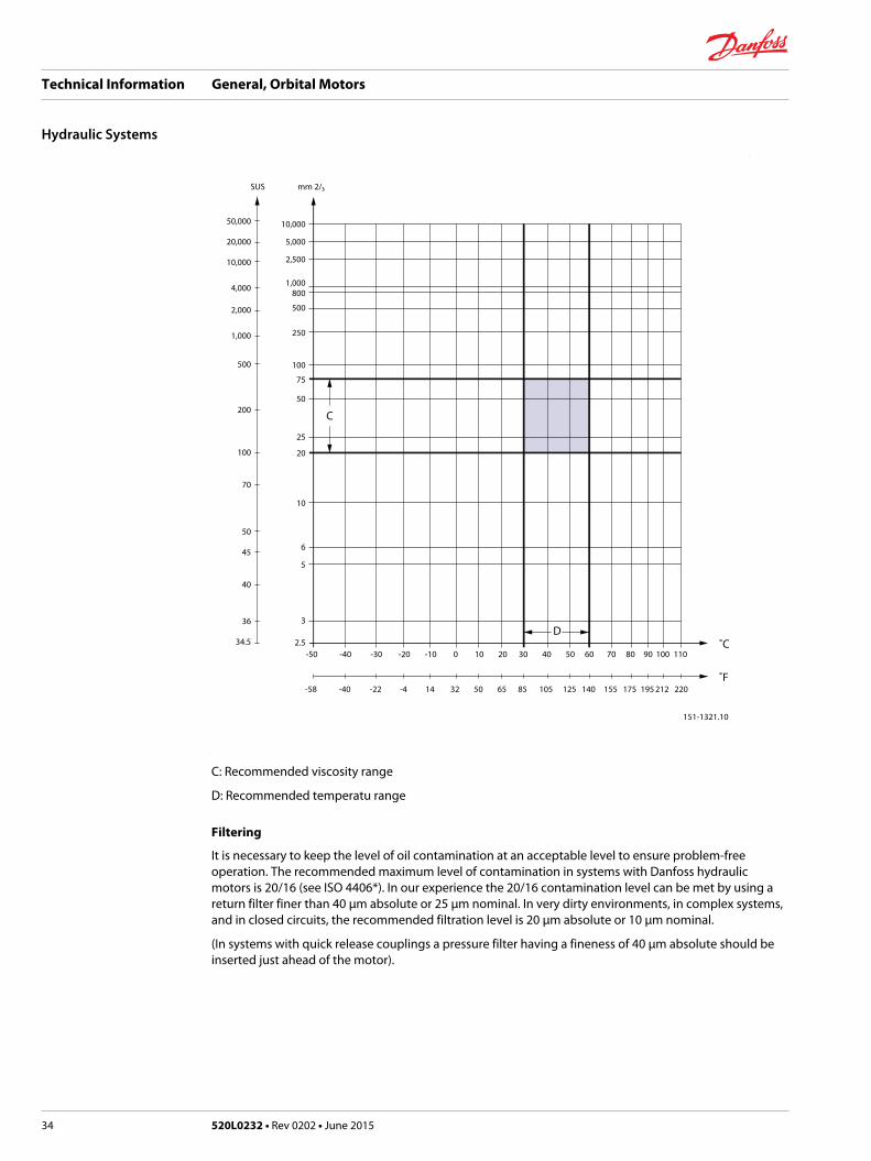
C: Recommended viscosity range
D: Recommended temperatu range
Filtering
It is necessary to keep the level of oil contamination at an acceptable level to ensure problem-freeoperation. The recommended maximum level of contamination in systems with Danfoss hydraulicmotors is 20/16 (see ISO 4406*). In our experience the 20/16 contamination level can be met by using areturn filter finer than 40 µm absolute or 25 µm nominal. In very dirty environments, in complex systems,and in closed circuits, the recommended filtration level is 20 µm absolute or 10 µm nominal.
(In systems with quick release couplings a pressure filter having a fineness of 40 µm absolute should beinserted just ahead of the motor).
Technical Information General, Orbital Motors
Hydraulic Systems
34 520L0232 • Rev 0202 • June 2015
Technical Information General, Orbital Motors
520L0232 • Rev 0202 • June 2015 35
Danfoss Power Solutions is a global manufacturer and supplier of high-quality hydraulic andelectronic components. We specialize in providing state-of-the-art technology and solutionsthat excel in the harsh operating conditions of the mobile off-highway market. Building onour extensive applications expertise, we work closely with our customers to ensureexceptional performance for a broad range of off-highway vehicles.
We help OEMs around the world speed up system development, reduce costs and bringvehicles to market faster.
Danfoss – Your Strongest Partner in Mobile Hydraulics.
Go to www.powersolutions.danfoss.com for further product information.
Wherever off-highway vehicles are at work, so is Danfoss. We offer expert worldwide supportfor our customers, ensuring the best possible solutions for outstanding performance. Andwith an extensive network of Global Service Partners, we also provide comprehensive globalservice for all of our components.
Please contact the Danfoss Power Solution representative nearest you.
Local address:
Danfoss Power Solutions GmbH & Co. OHGKrokamp 35D-24539 Neumünster, GermanyPhone: +49 4321 871 0
Danfoss Power Solutions ApSNordborgvej 81DK-6430 Nordborg, DenmarkPhone: +45 7488 2222
Danfoss Power Solutions (US) Company2800 East 13th StreetAmes, IA 50010, USAPhone: +1 515 239 6000
Danfoss Power Solutions Trading(Shanghai) Co., Ltd.Building #22, No. 1000 Jin Hai RdJin Qiao, Pudong New DistrictShanghai, China 201206Phone: +86 21 3418 5200
Danfoss can accept no responsibility for possible errors in catalogues, brochures and other printed material. Danfoss reserves the right to alter its products without notice. This also applies toproducts already on order provided that such alterations can be made without changes being necessary in specifications already agreed.All trademarks in this material are property of the respective companies. Danfoss and the Danfoss logotype are trademarks of Danfoss A/S. All rights reserved.
520L0232 • Rev 0202 • June 2015 www.danfoss.com © Danfoss A/S, 2015
Products we offer:
• Bent Axis Motors
• Closed Circuit Axial PistonPumps and Motors
• Displays
• Electrohydraulic PowerSteering
• Electrohydraulics
• Hydraulic Power Steering
• Integrated Systems
• Joysticks and ControlHandles
• Microcontrollers andSoftware
• Open Circuit Axial PistonPumps
• Orbital Motors
• PLUS+1® GUIDE
• Proportional Valves
• Sensors
• Steering
• Transit Mixer Drives
Comatrolwww.comatrol.com
Schwarzmüller-Inverterwww.schwarzmueller-inverter.com
Turolla www.turollaocg.com
Hydro-Gearwww.hydro-gear.com
Daikin-Sauer-Danfosswww.daikin-sauer-danfoss.com
Related Documents