Gating-ML 2.0 International Society for Advancement of Cytometry (ISAC) standard for representing gating descriptions in flow cytometry Josef Spidlen, ISAC Data Standards Task Force * , Ryan Brinkman Version 2.0 – 2015-03-16 Document Status Gating-ML has undergone several revisions since the first public release in February 2006. This doc- ument is part of the Gating-ML version 2.0 specification. It is based on the Gating-ML version 1.5, which became an International Society for Advancement of Cytometry (ISAC) Candidate Recommen- dation in January 2008. Based on feedback gathered from the implementors and development in the field, the Gating-ML version 2.0 has been developed. The current specification is an ISAC Recommendation that has been formally approved by the ISAC Data Standards Task Force and by ISAC Council on January 13, 2015. At this point, reference im- plementations have been developed and the specification has been formally tested to comply with the W3C XML schema version 1.0 specification, but no position is taken in respect to whether a particular software implementing this specification performs according to medical or other valid regulations. The work may be used under the terms of the Creative Commons Attribution-ShareAlike 3.0 Unported license. You are free to share (copy, distribute and transmit), and adapt the work under the conditions specified at http://creativecommons.org/licenses/by-sa/3.0/legalcode. Patent Disclaimer Attention is called to the possibility that implementation of this standard may require use of subject matter covered by patent rights. By publication of this standard, no position is taken with respect to the existence or validity of any patent rights in connection therewith. ISAC shall not be responsible for identifying patents or patent applications for which a license may be required to implement an ISAC standard or for conducting inquiries into the legal validity or scope of those patents that are brought to its attention. * List of ISAC Data Standards Task Force members provided in Annex C.

Welcome message from author
This document is posted to help you gain knowledge. Please leave a comment to let me know what you think about it! Share it to your friends and learn new things together.
Transcript
Gating-ML 2.0
International Society for Advancement of Cytometry (ISAC)standard for representing gating descriptions in flow cytometry
Josef Spidlen, ISAC Data Standards Task Force∗, Ryan Brinkman
Version 2.0 – 2015-03-16
Document Status
Gating-ML has undergone several revisions since the first public release in February 2006. This doc-ument is part of the Gating-ML version 2.0 specification. It is based on the Gating-ML version 1.5,which became an International Society for Advancement of Cytometry (ISAC) Candidate Recommen-dation in January 2008. Based on feedback gathered from the implementors and development in thefield, the Gating-ML version 2.0 has been developed.
The current specification is an ISAC Recommendation that has been formally approved by the ISACData Standards Task Force and by ISAC Council on January 13, 2015. At this point, reference im-plementations have been developed and the specification has been formally tested to comply with theW3C XML schema version 1.0 specification, but no position is taken in respect to whether a particularsoftware implementing this specification performs according to medical or other valid regulations.
The work may be used under the terms of the Creative Commons Attribution-ShareAlike 3.0 Unportedlicense. You are free to share (copy, distribute and transmit), and adapt the work under the conditionsspecified at http://creativecommons.org/licenses/by-sa/3.0/legalcode.
Patent Disclaimer
Attention is called to the possibility that implementation of this standard may require use of subjectmatter covered by patent rights. By publication of this standard, no position is taken with respect tothe existence or validity of any patent rights in connection therewith. ISAC shall not be responsiblefor identifying patents or patent applications for which a license may be required to implement anISAC standard or for conducting inquiries into the legal validity or scope of those patents that arebrought to its attention.
∗List of ISAC Data Standards Task Force members provided in Annex C.
http://flowcyt.sf.net/gating/latest.pdf Gating-ML – Gating Description in Flow Cytometry
To assure the highest-level of transparency and neutrality ISAC requires that all members ofthe Flow Cytometry Data Standards Task Force adhere to the Patent Disclosure Policy set forthbelow. ISAC undertakes to establish standards that do not require the purchase of patent licenses forcompliance. For this reason, Task Force members must immediately disclose any patents or patentapplications held by them and which they know or have reason to believe have a likelihood of beinginfringed by compliance with any draft or approved ISAC Recommendation. Users and reviewersare also encouraged to disclose any procedures that require a user to purchase a patent license. Inaddition, by participating in any ISAC Task Force, members affirm that, with respect to any patentthat may be infringed by compliance with any draft or approved ISAC Recommendation and is notdisclosed, such patent shall either (1) not be enforced with respect to such compliance, or (2) shall befreely licensed to all users on a fair, reasonable and non-discriminatory basis and without imposing alicensing fee or other charge of any kind. Every Task Force member shall at all times act in good faithand in an open and honest manner.
Abstract
The Flow Cytometry Standard (FCS) specification has been adopted for the common representationof flow cytometry data, and this standard is supported by all analytical instrument and third partysoftware suppliers. It includes data, metadata, and analysis components within the same file. However,metadata and analysis components, if included at all, are not recorded in a standardized fashionor in sufficient detail for use by independent parties. Also, the FCS standard is not sufficient toaccommodate for novel flow cytometry data, such as streaming or correlated waveform data or datacombining the visual power of microscopy with the statistical rigor of flow cytometry.
We propose to address these shortcomings via series of related data standards. This documentrepresents a specification on how to form unambiguous XML-based gate definitions. Such a descriptionof gates can facilitate the interchange and validation of data between different software packages withthe potential for significant increase of hardware and software interoperability. The specification sup-ports rectangular gates in n dimensions (i.e., from one-dimensional range gates up to n-dimensionalhyper-rectangular regions), quadrant gates in n dimensions, polygon gates, ellipsoid gates in n dimen-sions, and Boolean collections of any of the types of gates. Gates can be uniquely identified and maybe ordered into a hierarchical structure to describe a gating strategy. Gates may be applied on listmode data files (e.g., FCS files), which may be transformed as explicitly described. Transformationsincluding compensation description are included as part of the Gating-ML specification.
Keywords
flow cytometry, analytical cytology, gating, classification, data transformation, compensation, scale,spillover, spectrum, XML
Version 2.0 – 2015-03-16 — ISAC Recommendation — 2
http://flowcyt.sf.net/gating/latest.pdf Gating-ML – Gating Description in Flow Cytometry
Contents
List of Figures 6
List of Tables 6
1 Overview 91.1 Introduction . . . . . . . . . . . . . . . . . . . . . . . . . . . . . . . . . . . . . . 91.2 Scope . . . . . . . . . . . . . . . . . . . . . . . . . . . . . . . . . . . . . . . . . 91.3 Purpose . . . . . . . . . . . . . . . . . . . . . . . . . . . . . . . . . . . . . . . . 101.4 Normative references . . . . . . . . . . . . . . . . . . . . . . . . . . . . . . . . . 101.5 The content of this specification . . . . . . . . . . . . . . . . . . . . . . . . . . . 111.6 Namespaces and their prefixes within this document . . . . . . . . . . . . . . . . 11
2 Design principles and rationale 122.1 Supported gate and transformation types . . . . . . . . . . . . . . . . . . . . . . 122.2 Computationally simple determination of gate membership . . . . . . . . . . . . 132.3 Inclusion of transformations within Gating-ML . . . . . . . . . . . . . . . . . . . 13
2.3.1 Motivation . . . . . . . . . . . . . . . . . . . . . . . . . . . . . . . . . . . 132.3.2 Effects of nonlinear transformations . . . . . . . . . . . . . . . . . . . . . 132.3.3 Transforming the whole gate description into the data space . . . . . . . 14
2.4 Maximal utilization of XML schema validation . . . . . . . . . . . . . . . . . . . 162.5 Significant XML sibling elements order . . . . . . . . . . . . . . . . . . . . . . . 17
3 Terminology and requirements 183.1 Acronyms and abbreviations . . . . . . . . . . . . . . . . . . . . . . . . . . . . . 183.2 Mathematical symbols used . . . . . . . . . . . . . . . . . . . . . . . . . . . . . 183.3 Terminology . . . . . . . . . . . . . . . . . . . . . . . . . . . . . . . . . . . . . . 18
3.3.1 FCS dimension . . . . . . . . . . . . . . . . . . . . . . . . . . . . . . . . 183.3.2 Electronic event . . . . . . . . . . . . . . . . . . . . . . . . . . . . . . . . 203.3.3 List mode data file . . . . . . . . . . . . . . . . . . . . . . . . . . . . . . 203.3.4 Event value . . . . . . . . . . . . . . . . . . . . . . . . . . . . . . . . . . 203.3.5 Spillover, or spectrum, coefficient and matrix . . . . . . . . . . . . . . . . 213.3.6 Dependency . . . . . . . . . . . . . . . . . . . . . . . . . . . . . . . . . . 213.3.7 Dependency graph . . . . . . . . . . . . . . . . . . . . . . . . . . . . . . 213.3.8 Data transformation . . . . . . . . . . . . . . . . . . . . . . . . . . . . . 213.3.9 Scale transformation . . . . . . . . . . . . . . . . . . . . . . . . . . . . . 22
3.4 Conformance . . . . . . . . . . . . . . . . . . . . . . . . . . . . . . . . . . . . . 223.4.1 File conformance . . . . . . . . . . . . . . . . . . . . . . . . . . . . . . . 223.4.2 Applicability . . . . . . . . . . . . . . . . . . . . . . . . . . . . . . . . . 223.4.3 Software and hardware conformance . . . . . . . . . . . . . . . . . . . . . 22
4 General 234.1 Referencing dimensions . . . . . . . . . . . . . . . . . . . . . . . . . . . . . . . . 234.2 FCS dimensions and transformations . . . . . . . . . . . . . . . . . . . . . . . . 24
4.2.1 Gates applicable directly on uncompensated list mode data files . . . . . 244.2.2 Gates applicable on compensated data . . . . . . . . . . . . . . . . . . . 25
Version 2.0 – 2015-03-16 — ISAC Recommendation — 3

http://flowcyt.sf.net/gating/latest.pdf Gating-ML – Gating Description in Flow Cytometry
4.2.3 Gates applicable on data on transformed scales . . . . . . . . . . . . . . 264.2.4 Gates applicable on the ratio of two FCS dimensions . . . . . . . . . . . 274.2.5 Gates applicable on scaled ratio of two FCS dimensions . . . . . . . . . . 29
4.3 Results of gating operations . . . . . . . . . . . . . . . . . . . . . . . . . . . . . 294.4 Hierarchical gating and gating strategy description . . . . . . . . . . . . . . . . 304.5 Gating-ML file structure . . . . . . . . . . . . . . . . . . . . . . . . . . . . . . . 304.6 Gates overview . . . . . . . . . . . . . . . . . . . . . . . . . . . . . . . . . . . . 314.7 Scale transformations overview . . . . . . . . . . . . . . . . . . . . . . . . . . . . 314.8 Additional custom information . . . . . . . . . . . . . . . . . . . . . . . . . . . . 32
5 Gate description 335.1 Rectangular and range gates . . . . . . . . . . . . . . . . . . . . . . . . . . . . . 33
5.1.1 Definition . . . . . . . . . . . . . . . . . . . . . . . . . . . . . . . . . . . 335.1.2 Syntax specification . . . . . . . . . . . . . . . . . . . . . . . . . . . . . . 355.1.3 Validity conditions . . . . . . . . . . . . . . . . . . . . . . . . . . . . . . 365.1.4 Examples . . . . . . . . . . . . . . . . . . . . . . . . . . . . . . . . . . . 36
5.2 Polygon gates . . . . . . . . . . . . . . . . . . . . . . . . . . . . . . . . . . . . . 385.2.1 Definition . . . . . . . . . . . . . . . . . . . . . . . . . . . . . . . . . . . 385.2.2 Syntax specification . . . . . . . . . . . . . . . . . . . . . . . . . . . . . . 405.2.3 Validity conditions . . . . . . . . . . . . . . . . . . . . . . . . . . . . . . 415.2.4 Examples . . . . . . . . . . . . . . . . . . . . . . . . . . . . . . . . . . . 41
5.3 Ellipsoid gates . . . . . . . . . . . . . . . . . . . . . . . . . . . . . . . . . . . . . 445.3.1 Definition . . . . . . . . . . . . . . . . . . . . . . . . . . . . . . . . . . . 445.3.2 Syntax specification . . . . . . . . . . . . . . . . . . . . . . . . . . . . . . 475.3.3 Validity conditions . . . . . . . . . . . . . . . . . . . . . . . . . . . . . . 485.3.4 Examples . . . . . . . . . . . . . . . . . . . . . . . . . . . . . . . . . . . 49
5.4 Quadrant gates . . . . . . . . . . . . . . . . . . . . . . . . . . . . . . . . . . . . 495.4.1 Definition . . . . . . . . . . . . . . . . . . . . . . . . . . . . . . . . . . . 495.4.2 Syntax specification . . . . . . . . . . . . . . . . . . . . . . . . . . . . . . 525.4.3 Validity conditions . . . . . . . . . . . . . . . . . . . . . . . . . . . . . . 545.4.4 Examples . . . . . . . . . . . . . . . . . . . . . . . . . . . . . . . . . . . 55
5.5 Boolean gates . . . . . . . . . . . . . . . . . . . . . . . . . . . . . . . . . . . . . 565.5.1 Definition . . . . . . . . . . . . . . . . . . . . . . . . . . . . . . . . . . . 565.5.2 Syntax specification . . . . . . . . . . . . . . . . . . . . . . . . . . . . . . 585.5.3 Validity conditions . . . . . . . . . . . . . . . . . . . . . . . . . . . . . . 595.5.4 Examples . . . . . . . . . . . . . . . . . . . . . . . . . . . . . . . . . . . 59
6 Scale transformation description 616.1 Bounding transformations . . . . . . . . . . . . . . . . . . . . . . . . . . . . . . 61
6.1.1 Definition . . . . . . . . . . . . . . . . . . . . . . . . . . . . . . . . . . . 616.1.2 Use case description . . . . . . . . . . . . . . . . . . . . . . . . . . . . . 626.1.3 Syntax specification . . . . . . . . . . . . . . . . . . . . . . . . . . . . . . 626.1.4 Validity conditions . . . . . . . . . . . . . . . . . . . . . . . . . . . . . . 626.1.5 Examples . . . . . . . . . . . . . . . . . . . . . . . . . . . . . . . . . . . 62
6.2 Parametrized linear transformation – flin . . . . . . . . . . . . . . . . . . . . . 646.2.1 Definition . . . . . . . . . . . . . . . . . . . . . . . . . . . . . . . . . . . 64
Version 2.0 – 2015-03-16 — ISAC Recommendation — 4
http://flowcyt.sf.net/gating/latest.pdf Gating-ML – Gating Description in Flow Cytometry
6.2.2 Syntax specification . . . . . . . . . . . . . . . . . . . . . . . . . . . . . . 656.2.3 Validity conditions . . . . . . . . . . . . . . . . . . . . . . . . . . . . . . 656.2.4 Examples . . . . . . . . . . . . . . . . . . . . . . . . . . . . . . . . . . . 65
6.3 Parametrized logarithmic transformation – flog . . . . . . . . . . . . . . . . . . 666.3.1 Definition . . . . . . . . . . . . . . . . . . . . . . . . . . . . . . . . . . . 666.3.2 Syntax specification . . . . . . . . . . . . . . . . . . . . . . . . . . . . . . 676.3.3 Validity conditions . . . . . . . . . . . . . . . . . . . . . . . . . . . . . . 676.3.4 Examples . . . . . . . . . . . . . . . . . . . . . . . . . . . . . . . . . . . 67
6.4 Parametrized inverse hyperbolic sine transformation – fasinh . . . . . . . . . . 696.4.1 Definition . . . . . . . . . . . . . . . . . . . . . . . . . . . . . . . . . . . 696.4.2 Syntax specification . . . . . . . . . . . . . . . . . . . . . . . . . . . . . . 696.4.3 Validity conditions . . . . . . . . . . . . . . . . . . . . . . . . . . . . . . 706.4.4 Examples . . . . . . . . . . . . . . . . . . . . . . . . . . . . . . . . . . . 70
6.5 Logicle transformation . . . . . . . . . . . . . . . . . . . . . . . . . . . . . . . . 716.5.1 Definition . . . . . . . . . . . . . . . . . . . . . . . . . . . . . . . . . . . 716.5.2 Syntax specification . . . . . . . . . . . . . . . . . . . . . . . . . . . . . . 736.5.3 Validity conditions . . . . . . . . . . . . . . . . . . . . . . . . . . . . . . 746.5.4 Examples . . . . . . . . . . . . . . . . . . . . . . . . . . . . . . . . . . . 74
6.6 Hyperlog transformation . . . . . . . . . . . . . . . . . . . . . . . . . . . . . . . 766.6.1 Definition . . . . . . . . . . . . . . . . . . . . . . . . . . . . . . . . . . . 766.6.2 Syntax specification . . . . . . . . . . . . . . . . . . . . . . . . . . . . . . 776.6.3 Validity conditions . . . . . . . . . . . . . . . . . . . . . . . . . . . . . . 786.6.4 Examples . . . . . . . . . . . . . . . . . . . . . . . . . . . . . . . . . . . 78
7 Compensation description 807.1 Definition . . . . . . . . . . . . . . . . . . . . . . . . . . . . . . . . . . . . . . . 807.2 Syntax specification . . . . . . . . . . . . . . . . . . . . . . . . . . . . . . . . . . 807.3 Semantic specification . . . . . . . . . . . . . . . . . . . . . . . . . . . . . . . . 817.4 Validity conditions . . . . . . . . . . . . . . . . . . . . . . . . . . . . . . . . . . 817.5 Examples . . . . . . . . . . . . . . . . . . . . . . . . . . . . . . . . . . . . . . . 837.6 Compensation computing algorithm . . . . . . . . . . . . . . . . . . . . . . . . . 84
7.6.1 Standard compensation based on square spectrum (spillover) matrices . . 847.6.2 Compensation based on non-square spectrum matrices . . . . . . . . . . 85
8 Additional transformations description 868.1 Parametrized ratio transformation – fratio . . . . . . . . . . . . . . . . . . . . . 86
8.1.1 Definition . . . . . . . . . . . . . . . . . . . . . . . . . . . . . . . . . . . 868.1.2 Syntax specification . . . . . . . . . . . . . . . . . . . . . . . . . . . . . . 868.1.3 Validity conditions . . . . . . . . . . . . . . . . . . . . . . . . . . . . . . 878.1.4 Examples . . . . . . . . . . . . . . . . . . . . . . . . . . . . . . . . . . . 87
A References 90
B Summary of changes since Gating-ML 1.5 92
C ISAC Data Standards Task Force Members 94
Version 2.0 – 2015-03-16 — ISAC Recommendation — 5
http://flowcyt.sf.net/gating/latest.pdf Gating-ML – Gating Description in Flow Cytometry
List of Figures
1 A polygon gate created in a transformed space. . . . . . . . . . . . . . . . . . . 142 The effect of a logarithmic transformation on the shape of the gate. . . . . . . . 143 Example of a gate “changing dimensionality” in data space. . . . . . . . . . . . 154 Example of a gate stored as a bitmap image. . . . . . . . . . . . . . . . . . . . . 165 Work flow of data transformations prior to the application of a gate. . . . . . . . 256 Comparison of transformations with T = 1000, M = 4.5, W = 1, and A = 0. . . 337 Comparison of transformations with T = 1000, M = 4 or 5, W = 1 and A = 1. . 348 Example of a range gate. . . . . . . . . . . . . . . . . . . . . . . . . . . . . . . . 379 Example of a range gate. . . . . . . . . . . . . . . . . . . . . . . . . . . . . . . . 3710 Example of a rectangular gate. . . . . . . . . . . . . . . . . . . . . . . . . . . . . 3811 Example of a 3-dimensional rectangular gate with one unbound dimension. . . . 3912 Winding number method used to determine the interior of non-simple polygons. 4013 Example of a triangular polygon gate. . . . . . . . . . . . . . . . . . . . . . . . . 4214 Example of a pentagon polygon gate. . . . . . . . . . . . . . . . . . . . . . . . . 4315 Example of a polygon gate with crossing boundaries. . . . . . . . . . . . . . . . 4416 Ellipse with major and minor axes in line with the coordinate system. . . . . . . 4517 Example of a two dimensional ellipsoid gate. . . . . . . . . . . . . . . . . . . . . 5018 Example of a rotated two dimensional ellipsoid gate. . . . . . . . . . . . . . . . 5119 Demonstration of quadrant gates definitions. . . . . . . . . . . . . . . . . . . . . 5320 Example of a one dimensional quadrant gate. . . . . . . . . . . . . . . . . . . . 5521 Example of a quadrant gate with “merged” quadrants. . . . . . . . . . . . . . . 5822 Example of a Boolean OR gate. . . . . . . . . . . . . . . . . . . . . . . . . . . . 6123 The effect of transformation boundary as described section 6.1.5 (a). . . . . . . . 6424 The effect of increasing the W parameter in the Logicle transformation. . . . . . 7325 The effect of increasing the W parameter in the Hyperlog transformation. . . . . 77
List of Tables
1 XML namespaces used in this specification. . . . . . . . . . . . . . . . . . . . . 112 Space requirements for gates stored by bitmaps. . . . . . . . . . . . . . . . . . . 173 Acronyms and abbreviations used in this specification. . . . . . . . . . . . . . . 184 Mathematical symbols used in this specification. . . . . . . . . . . . . . . . . . . 195 Sample values of the flin transformation with various T and A. . . . . . . . . . 666 Sample values of the flog transformation with various T and M . . . . . . . . . . 687 Sample values of the fasinh transformation with various T , M and A. . . . . . . 708 Sample values of the Logicle transformation with various T , W , M , and A. . . . 759 Sample values of the Hyperlog transformation with various T , W , M , and A. . . 7910 Example of a simple 3× 3 spillover matrix. . . . . . . . . . . . . . . . . . . . . . 8411 Example of a simple 2× 3 spectrum matrix. . . . . . . . . . . . . . . . . . . . . 8412 Sample values of the fratio transformation with various A, B, and C. . . . . . . 87
Version 2.0 – 2015-03-16 — ISAC Recommendation — 6
http://flowcyt.sf.net/gating/latest.pdf Gating-ML – Gating Description in Flow Cytometry
List of Examples
1 Referencing FCS dimensions in gate definitions. . . . . . . . . . . . . . . . . . . . . . 232 Referencing the ratio of two FCS dimensions in gate definitions. . . . . . . . . . . . . 243 Gate applicable directly on uncompensated scale values of a list mode data file. . . . 264 Gate applicable on scale values compensated as defined in the FCS file. . . . . . . . . 275 Gate applicable on scale values compensated as defined in Gating-ML. . . . . . . . . 276 Gate applicable on scale values un-mixed as defined in Gating-ML. . . . . . . . . . . 287 Gate applicable on data on a Logicle scale. . . . . . . . . . . . . . . . . . . . . . . . . 288 Referencing scaled ratio of two FCS dimensions in a gate definition. . . . . . . . . . . 299 Gating-ML XML file demonstrating proper header definition. . . . . . . . . . . . . . . 3110 Custom info element at the top level of a Gating-ML file. . . . . . . . . . . . . . . . . 3411 Range gate definition. . . . . . . . . . . . . . . . . . . . . . . . . . . . . . . . . . . . 3612 Open range gate definition. . . . . . . . . . . . . . . . . . . . . . . . . . . . . . . . . 3713 Rectangular gate definition. . . . . . . . . . . . . . . . . . . . . . . . . . . . . . . . . 3814 Three-dimensional hyper-rectangular gate definition. . . . . . . . . . . . . . . . . . . 3915 Simple polygon gate definition. . . . . . . . . . . . . . . . . . . . . . . . . . . . . . . 4216 Polygon gate definition with transformation. . . . . . . . . . . . . . . . . . . . . . . . 4317 Polygon gate definition with crossing boundaries. . . . . . . . . . . . . . . . . . . . . 4418 Two-dimensional ellipsoid gate definition. . . . . . . . . . . . . . . . . . . . . . . . . . 4919 Rotated two-dimensional ellipsoid gate definition. . . . . . . . . . . . . . . . . . . . . 5020 Three-dimensional ellipsoid gate definition. . . . . . . . . . . . . . . . . . . . . . . . . 5221 Quadrant gate definition splitting the FSC-H dimension at multiple values. . . . . . . 5622 One dimensional quadrant gate definition. . . . . . . . . . . . . . . . . . . . . . . . . 5723 Quadrant gate definition demonstrating “merging” of quadrants. . . . . . . . . . . . . 5724 Boolean OR gate definition combining a rectangle gate with an ellipse gate. . . . . . . 6025 Boolean NOT gate definition. . . . . . . . . . . . . . . . . . . . . . . . . . . . . . . . 6026 Boolean AND gate definition with one operand used as complement. . . . . . . . . . 6127 Logicle transformation with a boundary restricting its result to the [0.1,0.9] interval. . 6228 Polygon gate referencing a transformation with a boundary. . . . . . . . . . . . . . . 6329 Inverse hyperbolic sine transformation with a left boundary. . . . . . . . . . . . . . . 6330 Ratio transformation with a boundary restricting its result to the [0.2, 5] interval. . . 6431 Parametrized linear transformation definition with T = 1000 and A = 0. . . . . . . . 6532 Parametrized linear transformation definition with T = 1000 and A = 100. . . . . . . 6633 Parametrized linear transformation definition with T = 1024 and A = 256. . . . . . . 6634 Parametrized linear transformation definition with a boundary. . . . . . . . . . . . . . 6635 Parametrized logarithmic transformation definition with T = 10000 and M = 5. . . . 6736 Parametrized logarithmic transformation definition with T = 1023 and M = 4.5. . . . 6837 Parametrized logarithmic transformation definition with T = 262144 and M = 4.5. . . 6838 Parametrized logarithmic transformation definition with a boundary. . . . . . . . . . 6839 Inverse hyperbolic sine transformation with T = 1000, M = 4 and A = 1. . . . . . . . 7040 Inverse hyperbolic sine transformation with T = 1000, M = 5 and A = 0. . . . . . . . 7141 Inverse hyperbolic sine transformation with T = 1000, M = 3 and A = 2. . . . . . . . 7142 Logicle transformation definition with T = 1000, W = 1, M = 4 and A = 0. . . . . . 7543 Logicle transformation definition with T = 1000, W = 1, M = 4, and A = 1. . . . . . 7544 Logicle transformation definition with T = 1000, W = 0, M = 4, and A = 1. . . . . . 75
Version 2.0 – 2015-03-16 — ISAC Recommendation — 7
http://flowcyt.sf.net/gating/latest.pdf Gating-ML – Gating Description in Flow Cytometry
45 Hyperlog transformation definition with T = 1000, W = 1, M = 4 and A = 0. . . . . 7846 Hyperlog transformation definition with T = 1000, W = 1, M = 4, and A = 1. . . . . 7947 Hyperlog transformation definition with T = 1000, W = 0, M = 4, and A = 1. . . . . 7948 Hyperlog transformation definition with a boundary. . . . . . . . . . . . . . . . . . . 7949 Definition of a spectrum (spillover) matrix. . . . . . . . . . . . . . . . . . . . . . . . . 8250 A simple 3× 3 spillover matrix definition. . . . . . . . . . . . . . . . . . . . . . . . . 8351 A simple 2× 3 spectrum matrix definition. . . . . . . . . . . . . . . . . . . . . . . . . 8452 Parametrized ratio transformation with A = 1, B = 0, and C = 0. . . . . . . . . . . . 8753 Parametrized ratio transformation with A = 1, B = 5 and C = 5. . . . . . . . . . . . 8854 Parametrized ratio transformation with A = 0.5, B = −10, and C = 25. . . . . . . . . 88
Version 2.0 – 2015-03-16 — ISAC Recommendation — 8
http://flowcyt.sf.net/gating/latest.pdf Gating-ML – Gating Description in Flow Cytometry
1 Overview
1.1 Introduction
In flow cytometry, gating is a well-known and highly important process for sorting and selectingpopulations of interests for further data acquisition or analysis. A standard formal way ofexchanging unambiguous descriptions of gates is crucial for interoperability among analyticalhardware and software applications. A gating description is also required by the MinimumInformation for a Flow Cytometry Experiment [1] recommendation.
Within this document we demonstrate how to form unambiguous XML-based gate defini-tions. Gating-ML description of gates can facilitate the interchange and validation of databetween different software packages with the potential for significant increase of hardware andsoftware interoperability. The specification supports rectangular gates in n dimensions (i.e.,from one-dimensional range gates up to n-dimensional hyper-rectangular regions), quadrantgates in n dimensions, polygon gates, ellipsoid gates in n dimensions, and Boolean collectionsof any of the types of gates. Gates can be uniquely identified and may be ordered into a hi-erarchical structure to describe a gating strategy. Gates may be applied on events as in listmode data files (e.g., scale values from the FCS files) or on transformed events as describedby an explicit scale transformation. If a data analysis involves transformed values, the trans-formation needs to be exactly described in order to reconstruct the analysis. Therefore, scaletransformation and compensation description are included as part of this specification.
The support for the Gating-ML specification as well as other related standards by softwaretools, journals, and scientists will significantly facilitate the reproduction of experiments andclinical measurements. Most importantly, these changes will allow scientists and software agentsto search, automatically process, and in particular understand both flow cytometry data andmetadata.
1.2 Scope
This document provides detailed specifications on how to form flow cytometry gate definitionsusing XML technology in order to computationally exchange details about post-acquisitionanalysis. The gate definitions are not primarily intended to define data acquisition or physicalsorting gates. Methodology chosen to describe gates in XML may not be optimal for instrumentacquisition or sorting settings.
Gates may be applied on raw data as in list mode data files or on data displayed usingvarious scales. Data compensation as well as other transformations may be performed priorto applying gates. If analyses involve transformed data, then the transformation needs to beexactly described in order to reconstruct the analyses. For example, if a gate is created usingnonlinearly transformed event values, the transformation needs to be described in order toreconstruct the gate. Therefore, scale transformation and compensation are included as partof this specification; see section 2.3 for more details.
This document does not cover guidelines (protocols, SOPs) on how gates ought to be formedin order to define specific populations, i.e., how to create gates or what gating strategies oughtto be used for particular assays.
Version 2.0 – 2015-03-16 — ISAC Recommendation — 9
http://flowcyt.sf.net/gating/latest.pdf Gating-ML – Gating Description in Flow Cytometry
1.3 Purpose
Gating in flow cytometry is a well-known and highly important process for selecting popu-lations of interest by defining the characteristics of particles for further data acquisition oranalysis. Although flow cytometry has a successful data format standard [2], it does not in-clude a full representation of gates. This prevents a variety of collaborative opportunities torecreate experimental methods and results.
The purpose of this document is to standardize the description of flow cytometry gate defi-nitions. It facilitates cross-platform sharing of gates, enables the interchange of gate definitionsbetween different software packages, and provides the means to integrate methods with resultsin flow cytometry reporting.
1.4 Normative references
The following referenced documents are indispensable for the application of this standard. Fordated references, only the edition cited applies. For undated references, the latest edition ofthe referenced document (including any amendments or corrigenda) applies.
• W3C Recommendation, Extensible Markup Language (XML) 1.0 (Fourth Edition) [3].
• W3C Recommendation, Namespaces in XML 1.0 (Third Edition) [4].
• W3C Recommendation, XML Schema 1.1 Part 1: Structures [5].
• W3C Recommendation, XML Schema 1.1 Part 2: Datatypes [6].
The following documents are useful for the application of this standard. They represent otherstandards and standard proposals relevant for understanding of this specification or intendedto describe or store flow cytometry data and meta-data together with information about flowcytometry experiments and analyses.
• Spidlen J, Moore W, Parks D, Goldberg M, Bray C, Bierre P, Gorombey P, Hyun B,Hubbard M, Lange S, Lefebvre R, Leif R, Novo D, Ostruszka L, Treister A, Wood J,Murphy RF, Roederer M, Sudar D, Zigon R and Brinkman RR. Data File Standard forFlow Cytometry, version FCS 3.1 [2].
• Lee J, Spidlen J, Boyce K, Cai J, Dalphin M, Gasparetto M, Goldberg M, Jansen K, KongM, Nikolich-Zugich J, Moloshok T, Parrish D, Qian Y, Selvaraj B, Smith C, TchuvatkinaO, Wilkinson P, Wilson C, Scheuermann R, and Brinkman R. MIFlowCyt: MinimumInformation about a Flow Cytometry Experiment [1].
• Seamer LC, Bagwell CB, Barden L, Redelman D, Salzman GC, Wood JC, and MurphyRF. Proposed new data file standard for flow cytometry, version FCS 3.0 [7].
Version 2.0 – 2015-03-16 — ISAC Recommendation — 10
http://flowcyt.sf.net/gating/latest.pdf Gating-ML – Gating Description in Flow Cytometry
1.5 The content of this specification
This specification consists of the following parts:
(a) Normative: This document providing a detailed description of the Gating-ML specifica-tion.
(b) Normative: The XML schemas Gating-ML.v2.0.xsd, Transformations.v2.0.xsd, andDataTypes.v2.0.xsd defining syntax of Gating-ML compliant files and usable to val-idate Gating-ML XML documents. Within this document, the Gating-ML.v2.0.xsd,Transformations.v2.0.xsd, and DataTypes.v2.0.xsd files are referenced as the XMLschemas or the schemas. The XML schemas can also be obtained from the following URLs:
• http://flowcyt.sourceforge.net/gating/2.0/xsd/Gating-ML.v2.0.xsd
• http://flowcyt.sourceforge.net/gating/2.0/xsd/Transformations.v2.0.xsd
• http://flowcyt.sourceforge.net/gating/2.0/xsd/DataTypes.v2.0.xsd
(c) Informative: Examples of Gating-ML files.
(d) Informative: Gating-ML software compliance tests – a set of tests to determine Gating-ML compliance of third party software.
(e) Informative: Gating-ML reference implementation.
All the components of this standard are available from World Wide Web at http://www.
isac-net.org/. The specification may also be downloaded from http://flowcyt.sourceforge.
net/.
1.6 Namespaces and their prefixes within this document
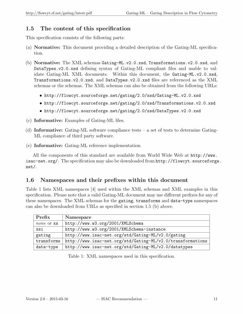
Table 1 lists XML namespaces [4] used within the XML schemas and XML examples in thisspecification. Please note that a valid Gating-ML document may use different prefixes for any ofthese namespaces. The XML schemas for the gating, transforms and data-type namespacescan also be downloaded from URLs as specified in section 1.5 (b) above.
Prefix Namespacenone or xs http://www.w3.org/2001/XMLSchema
xsi http://www.w3.org/2001/XMLSchema-instance
gating http://www.isac-net.org/std/Gating-ML/v2.0/gating
transforms http://www.isac-net.org/std/Gating-ML/v2.0/transformations
data-type http://www.isac-net.org/std/Gating-ML/v2.0/datatypes
Table 1: XML namespaces used in this specification.
Version 2.0 – 2015-03-16 — ISAC Recommendation — 11
http://flowcyt.sf.net/gating/latest.pdf Gating-ML – Gating Description in Flow Cytometry
2 Design principles and rationale
2.1 Supported gate and transformation types
This specification supports four types of gates: rectangular gates in n dimensions (i.e., fromone-dimensional range gates up to n-dimensional hyper-rectangular regions), quadrant gates inn dimensions, polygon gates (in 2 dimensions), ellipsoid gates in n dimensions, and Booleancollections of any of the types of gates. Supported gate types have been selected based onfeedback on Gating-ML 1.5 in order to keep the specification simple while accommodate futureinnovations in automated multidimensional gating and clustering in a generic way.
Gates may be applied on data as in list mode data files or on transformed data. If gatesare applied on transformed data then the exact description of data transformation needs tobe provided in order to reconstruct the analysis. This specification supports open transfor-mations (i.e., published and free to use) which have been shown useful for display or analysisof cytometry data, such as Logicle and Hyperlog. In addition, transformations such as linear,logarithmic, and inverse hyperbolic sine are supported and have been extended to allow foradditional parameterization and tweaking specifically for the display of flow cytometry data.These extensions are called FLin, FLog and FASinH, respectively. Finally, a parametrized ra-tio of two FCS dimensions (i.e., FRatio) and fluorescence compensation complete the list ofsupported transformations.
Compared to Gating-ML 1.5, the list of supported transformations has been shortened byomitting transformations that have not been found particularly useful or are no longer necessarydue to additional design changes. Inverse transformations are no longer automatically included.In addition, values from FCS files [2] are referenced as scale values (used to be channel values inGating-ML 1.5), which eliminates the necessity to encode the channel-to-scale transformationin Gating-ML (this transformation is unambiguously captured by keywords in the FCS data filestandard). Finally, Gating-ML 2.0 no longer supports compound transformations in general.Instead, each gate dimension can be defined referencing up to one “scale” transformation plusan optional fluorescence compensation description applied on an FCS dimension, which maybe an FCS dimension from a list mode data file or the result of an additional transformation,i.e., the ratio of two FCS dimensions. All these changes have been made based on communityfeedback in order to significantly simplify the Gating-ML specification, especially for Gating-MLconsumers (readers). Consequently, the full implementation of Gating-ML 2.0 is significantlysimpler than Gating-ML 1.5, which will facilitate interoperability among flow cytometry dataanalysis tools.
Also based on community feedback, this specification does not include any transformationsor other components that may require use of subject matter covered by patents and may onlybe available under restrictive licensing conditions to some groups. However, by publication ofthis standard, no position is taken with respect to the existence or validity of any patent rightsin connection therewith. ISAC shall not be responsible for identifying patents or patent appli-cations for which a license may be required to implement an ISAC standard or for conductinginquiries into the legal validity or scope of those patents that are brought to its attention.
Originally, we have investigated the possibilities of reusing MathML [8] to universally de-scribe any kind of mathematical transformation. While this would be a very flexible solution,it is generally impossible to evaluate expressions describable by MathML. Therefore, we haveabandoned the MathML-based approach.
Version 2.0 – 2015-03-16 — ISAC Recommendation — 12

http://flowcyt.sf.net/gating/latest.pdf Gating-ML – Gating Description in Flow Cytometry
2.2 Computationally simple determination of gate membership
The specification has been designed with respect to computational simplicity of gate processing.Specifically, the description of gates has been designed to be able to make computationallysimple decisions whether a particular event is in a particular gate. This aspect can especiallybe identified in the description of ellipsoid gates using covariance matrices (see section 5.3).
2.3 Inclusion of transformations within Gating-ML
This section describes the rationale for inclusion of transformations in Gating-ML and fordescription of gates in the space where they have been created rather than in the original dataspace.
2.3.1 Motivation
– Why do we care about transformations when describing gates?
In most flow cytometry applications, fluorescence signals of interest can range from high valuesdown to essentially zero. Depending on the signal evaluation system, primary measurementsmay or may not include negative data values. After fluorescence compensation, some cell pop-ulations will have low means and will include events with negative data values. Logarithmicpresentation has been very useful in providing informative displays of wide-ranging flow cytom-etry data, and several other transformations have been introduced to adequately display cellpopulations with low means and high variances and, in particular, negative data values. Typi-cally, transformations are performed to store fluorescence data more efficiently, to provide morecomplete, appropriate, and readily interpretable data representations, or to achieve optimaldisplay of that data.
If transformed data are used for analysis (e.g., data are viewed on a transformed scale whilecreating a gate), the transformation needs to be exactly reported in order to unambiguouslyinterpret or reconstruct the analysis. As gating description is highly dependent on being ableto describe these transformations, we have placed these into a single specification. Below westate the rationale for the inclusion of transformations in Gating-ML and for designing thespecification in a way that gates are described in the space where they have been created ratherthan transformed into the space where the acquired list mode data is stored.
2.3.2 Effects of nonlinear transformations
– Why not to only transform the vertices of the gate into the data space and store these?
Let us demonstrate the effects of a nonlinear transformation on the shape of a gate by a simpleexample, which shows the difference between recording a transformation versus transformingthe coordinates of gate vertices and reporting these.
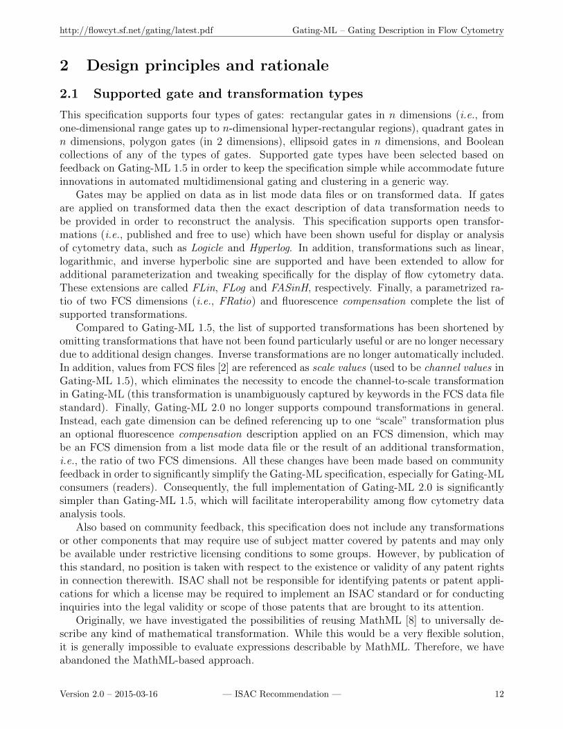
The example involves two variables: x and y; the data are stored in a linear space. Thevariable x is transformed from linear to logarithmic scale and it is visualized using logarithmicscale; the variable y remains on the linear scale. Using this visualization (transformed space),a polygon gate has been created: vertices at (1, 10), (3, 30), and (1, 30), Figure 1.
However, if we would create a polygon gate in the original space using the correspondingcoordinates of the gate vertices in the linear data space, i.e., the points (10, 10), (1000, 30),
Version 2.0 – 2015-03-16 — ISAC Recommendation — 13
http://flowcyt.sf.net/gating/latest.pdf Gating-ML – Gating Description in Flow Cytometry
Figure 1: A polygon gate created in a transformed space.
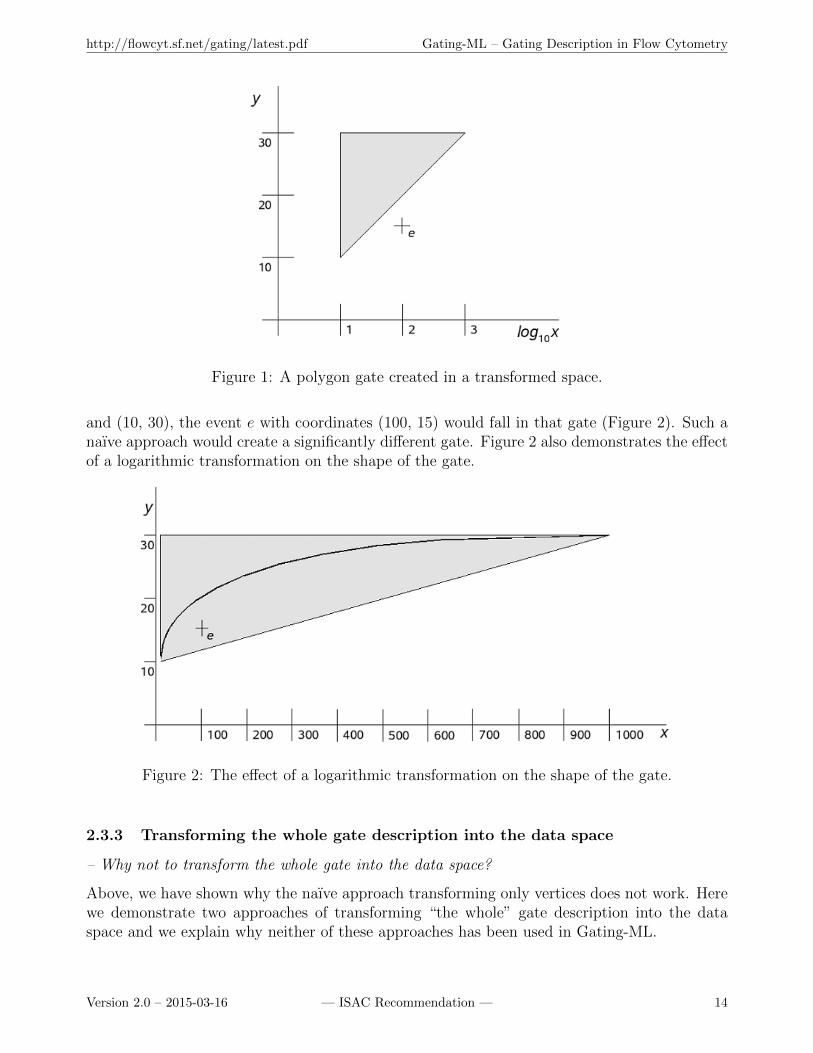
and (10, 30), the event e with coordinates (100, 15) would fall in that gate (Figure 2). Such anaıve approach would create a significantly different gate. Figure 2 also demonstrates the effectof a logarithmic transformation on the shape of the gate.
Figure 2: The effect of a logarithmic transformation on the shape of the gate.
2.3.3 Transforming the whole gate description into the data space
– Why not to transform the whole gate into the data space?
Above, we have shown why the naıve approach transforming only vertices does not work. Herewe demonstrate two approaches of transforming “the whole” gate description into the dataspace and we explain why neither of these approaches has been used in Gating-ML.
Version 2.0 – 2015-03-16 — ISAC Recommendation — 14
http://flowcyt.sf.net/gating/latest.pdf Gating-ML – Gating Description in Flow Cytometry
Alternative Approach 1: Transform gate vertices into the data space and describe(using mathematical formulas) how edges “have been curved”.
In the example stated above, we would obtain a “polygon-like gate with vertices (10, 10), (1000,30), and (10, 30), where the edge from (10, 10) to (1000, 30) is a logarithmic curve”.
Rationale for avoiding this approach
• This description (formulas) would be significantly difficult to create. Our example showsa two dimensional gate with only one dimension affected by the transformations. The“curving” gets complicated when a more complicated transformation is used (Logicle,Hyperlog, ...) or when both the dimensions are transformed, which is often the case.Moreover, multidimensional gates would have to be described by “curved” half-spaces,which would become challenging.
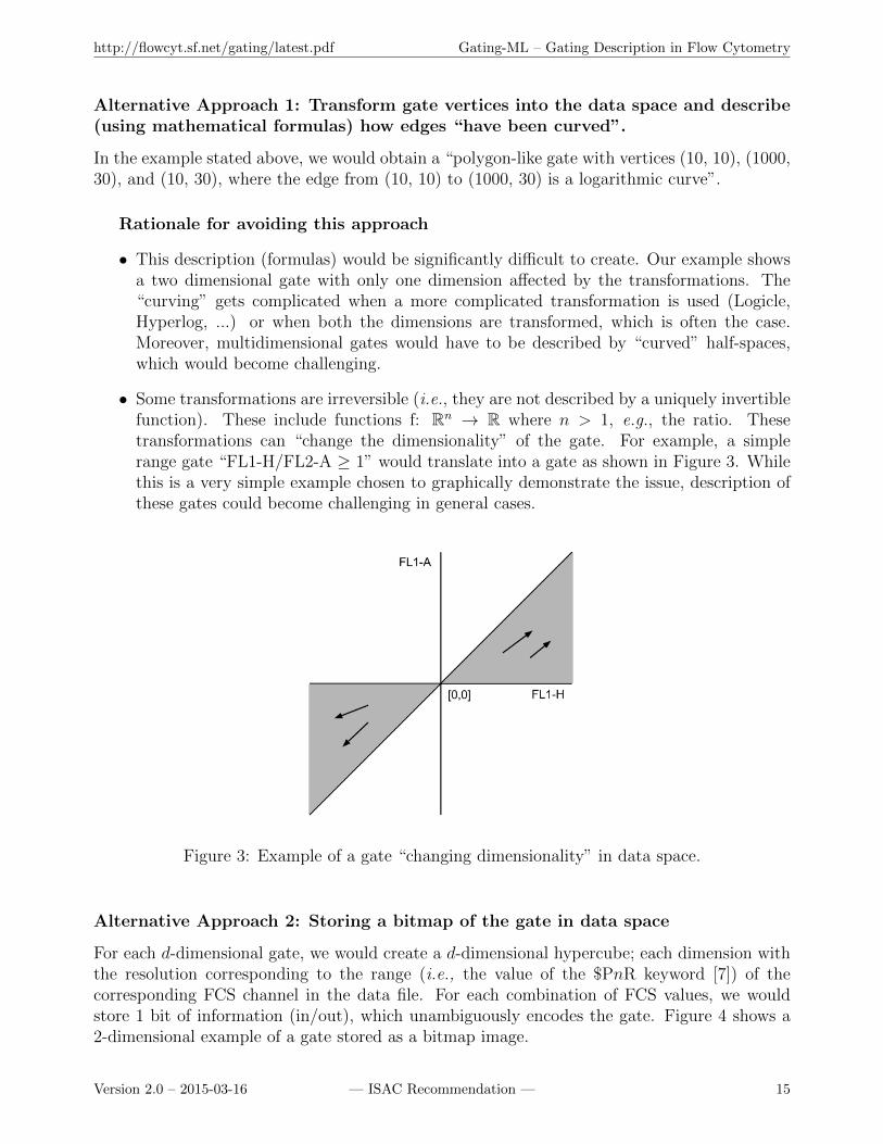
• Some transformations are irreversible (i.e., they are not described by a uniquely invertiblefunction). These include functions f: Rn → R where n > 1, e.g., the ratio. Thesetransformations can “change the dimensionality” of the gate. For example, a simplerange gate “FL1-H/FL2-A ≥ 1” would translate into a gate as shown in Figure 3. Whilethis is a very simple example chosen to graphically demonstrate the issue, description ofthese gates could become challenging in general cases.
Figure 3: Example of a gate “changing dimensionality” in data space.
Alternative Approach 2: Storing a bitmap of the gate in data space
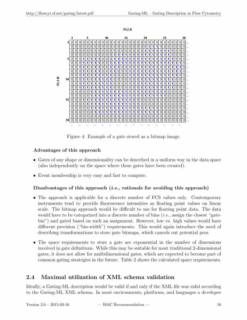
For each d-dimensional gate, we would create a d-dimensional hypercube; each dimension withthe resolution corresponding to the range (i.e., the value of the $PnR keyword [7]) of thecorresponding FCS channel in the data file. For each combination of FCS values, we wouldstore 1 bit of information (in/out), which unambiguously encodes the gate. Figure 4 shows a2-dimensional example of a gate stored as a bitmap image.
Version 2.0 – 2015-03-16 — ISAC Recommendation — 15
http://flowcyt.sf.net/gating/latest.pdf Gating-ML – Gating Description in Flow Cytometry
Figure 4: Example of a gate stored as a bitmap image.
Advantages of this approach
• Gates of any shape or dimensionality can be described in a uniform way in the data space(also independently on the space where these gates have been created).
• Event membership is very easy and fast to compute.
Disadvantages of this approach (i.e., rationale for avoiding this approach)
• The approach is applicable for a discrete number of FCS values only. Contemporaryinstruments tend to provide fluorescence intensities as floating point values on linearscale. The bitmap approach would be difficult to use for floating point data. The datawould have to be categorized into a discrete number of bins (i.e., assign the closest “gate-bin”) and gated based on such an assignment. However, low vs. high values would havedifferent precision (“bin-width”) requirements. This would again introduce the need ofdescribing transformations to store gate bitmaps, which cancels out potential pros.
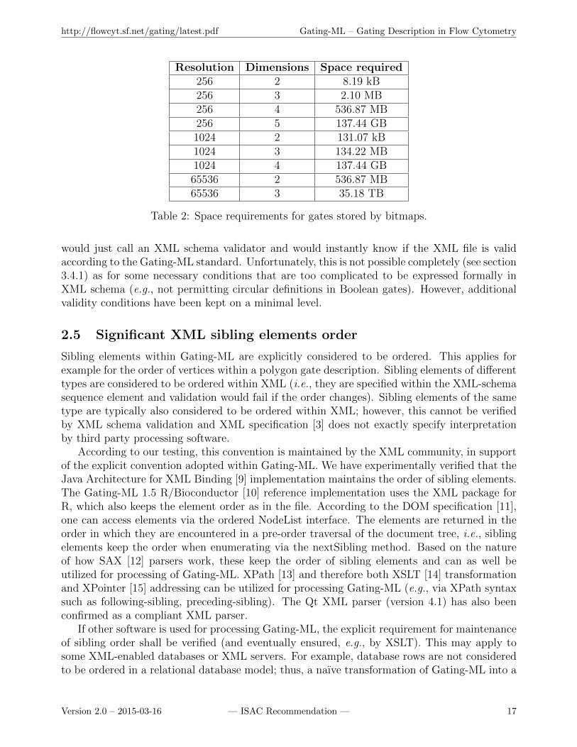
• The space requirements to store a gate are exponential in the number of dimensionsinvolved in gate definitions. While this may be suitable for most traditional 2-dimensionalgates, it does not allow for multidimensional gates, which are expected to become part ofcommon gating strategies in the future. Table 2 shows the calculated space requirements.
2.4 Maximal utilization of XML schema validation
Ideally, a Gating-ML description would be valid if and only if the XML file was valid accordingto the Gating-ML XML schema. In most environments, platforms, and languages a developer
Version 2.0 – 2015-03-16 — ISAC Recommendation — 16
http://flowcyt.sf.net/gating/latest.pdf Gating-ML – Gating Description in Flow Cytometry
Resolution Dimensions Space required256 2 8.19 kB256 3 2.10 MB256 4 536.87 MB256 5 137.44 GB1024 2 131.07 kB1024 3 134.22 MB1024 4 137.44 GB65536 2 536.87 MB65536 3 35.18 TB
Table 2: Space requirements for gates stored by bitmaps.
would just call an XML schema validator and would instantly know if the XML file is validaccording to the Gating-ML standard. Unfortunately, this is not possible completely (see section3.4.1) as for some necessary conditions that are too complicated to be expressed formally inXML schema (e.g., not permitting circular definitions in Boolean gates). However, additionalvalidity conditions have been kept on a minimal level.
2.5 Significant XML sibling elements order
Sibling elements within Gating-ML are explicitly considered to be ordered. This applies forexample for the order of vertices within a polygon gate description. Sibling elements of differenttypes are considered to be ordered within XML (i.e., they are specified within the XML-schemasequence element and validation would fail if the order changes). Sibling elements of the sametype are typically also considered to be ordered within XML; however, this cannot be verifiedby XML schema validation and XML specification [3] does not exactly specify interpretationby third party processing software.
According to our testing, this convention is maintained by the XML community, in supportof the explicit convention adopted within Gating-ML. We have experimentally verified that theJava Architecture for XML Binding [9] implementation maintains the order of sibling elements.The Gating-ML 1.5 R/Bioconductor [10] reference implementation uses the XML package forR, which also keeps the element order as in the file. According to the DOM specification [11],one can access elements via the ordered NodeList interface. The elements are returned in theorder in which they are encountered in a pre-order traversal of the document tree, i.e., siblingelements keep the order when enumerating via the nextSibling method. Based on the natureof how SAX [12] parsers work, these keep the order of sibling elements and can as well beutilized for processing of Gating-ML. XPath [13] and therefore both XSLT [14] transformationand XPointer [15] addressing can be utilized for processing Gating-ML (e.g., via XPath syntaxsuch as following-sibling, preceding-sibling). The Qt XML parser (version 4.1) has also beenconfirmed as a compliant XML parser.
If other software is used for processing Gating-ML, the explicit requirement for maintenanceof sibling order shall be verified (and eventually ensured, e.g., by XSLT). This may apply tosome XML-enabled databases or XML servers. For example, database rows are not consideredto be ordered in a relational database model; thus, a naıve transformation of Gating-ML into a
Version 2.0 – 2015-03-16 — ISAC Recommendation — 17

http://flowcyt.sf.net/gating/latest.pdf Gating-ML – Gating Description in Flow Cytometry
database structure could eventually change the content of the Gating-ML document. However,based on our research, several database servers (e.g., Oracle, IBM DB2) use “hidden columns”to store and maintain the sibling order automatically without any additional user effort.
3 Terminology and requirements
3.1 Acronyms and abbreviations
Table 3 lists acronyms and abbreviations used in this specification.
Acronym / Abbreviation DescriptionDOM Document Object ModelFCS Flow Cytometry StandardFLx The signal from a fluorescence detector x (x ∈ N)FSC Forward ScatterDSTF Data Standards Task ForceHTML Hypertext Markup LanguageISAC International Society for Advancement of CytometryJAXB Java Architecture for XML BindingRFC Request for CommentsSAX Simple API for XMLSSC Side ScatterURI Uniform Resource IdentifierURL Uniform Resource LocatorW3C World Wide Web ConsortiumXML Extensible Markup LanguageXSL Extensible Stylesheet LanguageXSLT XSL Transformations
Table 3: Acronyms and abbreviations used in this specification.
3.2 Mathematical symbols used
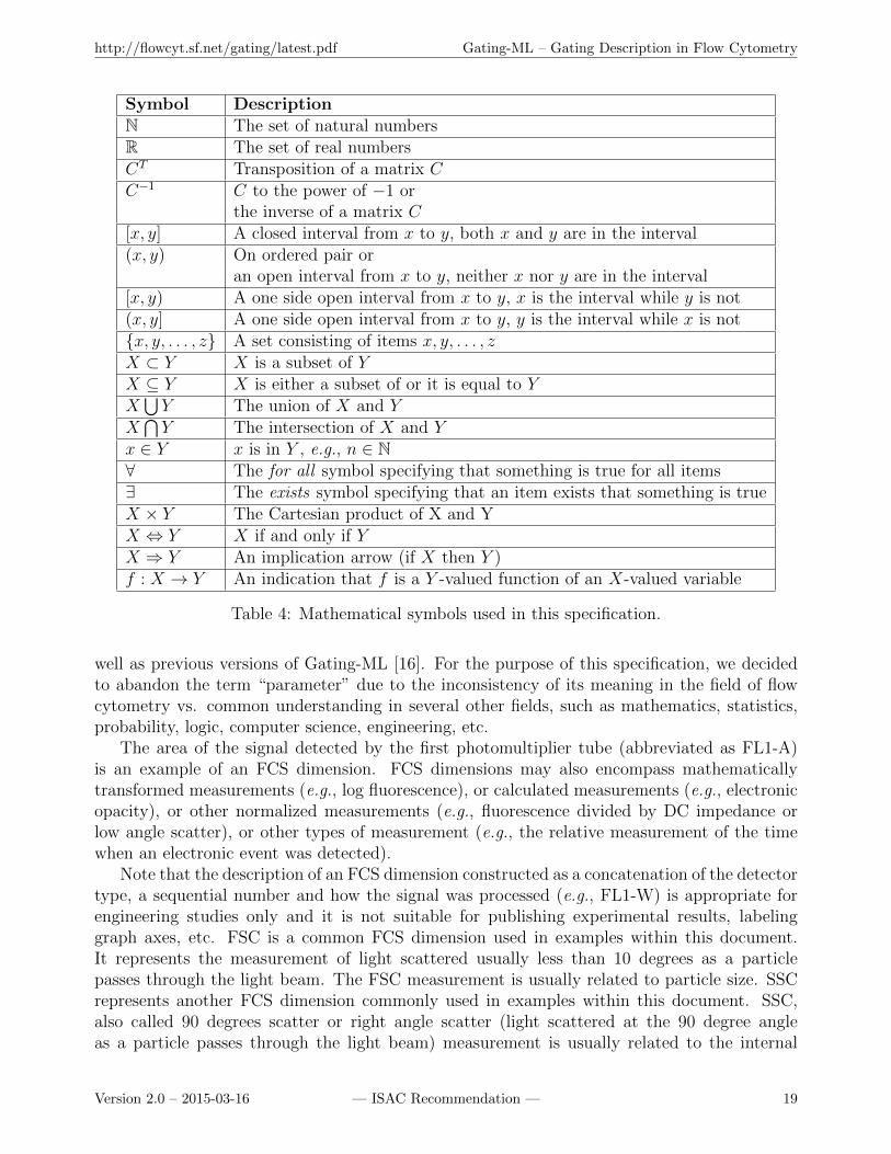
Table 4 lists the mathematical symbols used in this specification.
3.3 Terminology
3.3.1 FCS dimension
An FCS dimension within this document is understood as a type of measurement or other char-acteristic or quality, typically based on (or derived from) a measurement, which is captured (orcapturable) in a list-mode data file (e.g., an FCS file) on a per-event basis. These measure-ments are typically based on a signal (or signals) produced by a detector (or several detectors)of an analytical instrument (typically a flow cytometry analyzer, cell sorter, or mass cytometer).Please note that an FCS dimension is called a “parameter” in the FCS data file standard [2] as
Version 2.0 – 2015-03-16 — ISAC Recommendation — 18
http://flowcyt.sf.net/gating/latest.pdf Gating-ML – Gating Description in Flow Cytometry
Symbol DescriptionN The set of natural numbersR The set of real numbersCT Transposition of a matrix CC−1 C to the power of −1 or
the inverse of a matrix C[x, y] A closed interval from x to y, both x and y are in the interval(x, y) On ordered pair or
an open interval from x to y, neither x nor y are in the interval[x, y) A one side open interval from x to y, x is the interval while y is not(x, y] A one side open interval from x to y, y is the interval while x is not{x, y, . . . , z} A set consisting of items x, y, . . . , zX ⊂ Y X is a subset of YX ⊆ Y X is either a subset of or it is equal to YX⋃Y The union of X and Y
X⋂Y The intersection of X and Y
x ∈ Y x is in Y , e.g., n ∈ N∀ The for all symbol specifying that something is true for all items∃ The exists symbol specifying that an item exists that something is trueX × Y The Cartesian product of X and YX ⇔ Y X if and only if YX ⇒ Y An implication arrow (if X then Y )f : X → Y An indication that f is a Y -valued function of an X-valued variable
Table 4: Mathematical symbols used in this specification.
well as previous versions of Gating-ML [16]. For the purpose of this specification, we decidedto abandon the term “parameter” due to the inconsistency of its meaning in the field of flowcytometry vs. common understanding in several other fields, such as mathematics, statistics,probability, logic, computer science, engineering, etc.
The area of the signal detected by the first photomultiplier tube (abbreviated as FL1-A)is an example of an FCS dimension. FCS dimensions may also encompass mathematicallytransformed measurements (e.g., log fluorescence), or calculated measurements (e.g., electronicopacity), or other normalized measurements (e.g., fluorescence divided by DC impedance orlow angle scatter), or other types of measurement (e.g., the relative measurement of the timewhen an electronic event was detected).
Note that the description of an FCS dimension constructed as a concatenation of the detectortype, a sequential number and how the signal was processed (e.g., FL1-W) is appropriate forengineering studies only and it is not suitable for publishing experimental results, labelinggraph axes, etc. FSC is a common FCS dimension used in examples within this document.It represents the measurement of light scattered usually less than 10 degrees as a particlepasses through the light beam. The FSC measurement is usually related to particle size. SSCrepresents another FCS dimension commonly used in examples within this document. SSC,also called 90 degrees scatter or right angle scatter (light scattered at the 90 degree angleas a particle passes through the light beam) measurement is usually related to the internal
Version 2.0 – 2015-03-16 — ISAC Recommendation — 19
http://flowcyt.sf.net/gating/latest.pdf Gating-ML – Gating Description in Flow Cytometry
granularity or complexity of a particle.Within this document, FCS dimensions correspond to dimensions creating the multidimen-
sional space where gates are formed. Also, FCS dimension may be transformed as describedfurther in this document.
3.3.2 Electronic event
An electronic event within this document is understood as a unit of data that has been generatedas a response to a signal occurrence detected by an analytical instrument. An electronic eventis a vector (record) that has a value (see section 3.3.4) for each FCS dimension. Electronicevents typically describe characteristics of a single particle (e.g., a cell) and they are typicallystored in list mode data files (i.e, FCS files).
3.3.3 List mode data file
A list mode data file is a file containing a sequential list of events. List mode data files aretypically used for event-by-event data acquisition. Currently, FCS [2] is the most widely (andalmost solely) used list mode data file format in flow cytometry, although the FCS specificationsupports both list mode data and histograms. Gates can only be applied on list mode data(not on histograms).
Although some data files may contain more than one data set, for the purpose of thisdocument, we consider a list mode data file equal to a list mode data set, i.e., each list modedata file containing a single sequential list of events. As of FCS version 3.1, the usage of multipledata sets within a single data file is deprecated unless the multiple data sets are derived onefrom another.
3.3.4 Event value
An event value is the value recorded for a particular event in a particular FCS dimension. Ifthe used list mode data file format prescribes implicit transformations to decode data, thenthese shall be applied prior to any transformation that may be described by Gating-ML.
Specifically, values of events stored in FCS data files shall be decoded and converted tothe form of so-called “scale values” as specified by the FCS [2] specification. This involvesinterpretation of several FCS keywords (e.g., $DATATYPE, $BYTEORD, $PnB, $PnE, $PnR, $PnG).For example, let us assume that the value of the $DATATYPE keyword is “I” (indicating that theinteger data type is being used), the value of the $BYTEORD keyword is “4,3,2,1” (indicatingthat the big endian byte order is used), the value of the $MODE keyword is “L” (indicating thatlist mode data is being stored), the value of the $PAR keyword is “8” (indicating that eightdifferent FCS dimensions are captured), the value of the $TOT keyword is “73965” (indicatingthat there are 73965 electronic events captured in the FCS data set), the value of all 8 $PnBkeywords (i.e., for n ∈ N, n ≤ 8) is “16” (indicating that there are 2 bytes used to storeeach value), the value of the $P3N keyword is “FL1-H” (indicating that the short name of thethird FCS dimension is FL1-H), the value of the $P3R keyword is “1024” (indicating that the“range” value for the third FCS dimension is 1024), the value of the $P3E keyword is “4,1”(indicating that the third FCS dimension is stored on a logarithmic scale) and finally, that the$P3G keyword is not present. Let us further assume that the data segment of our FCS datafile starts with the following byte sequence (shown in hexadecimal notation): 00 C5 00 96
Version 2.0 – 2015-03-16 — ISAC Recommendation — 20
http://flowcyt.sf.net/gating/latest.pdf Gating-ML – Gating Description in Flow Cytometry
01 AF 00 FF 00 FC 01 14 ... Based on this example, we can decode (calculate) the (scale)value of the FL1-H dimension of the first event as 10(4∗431/1024) = 48.26071 (the 01 AF bytesequence represents the value of 431 in the big endian binary integer encoding, which is furthertransformed as prescribed by the FCS specification).
3.3.5 Spillover, or spectrum, coefficient and matrix
Spillover or spectrum coefficient from FCS dimension X to FCS dimension Y is the ratio ofthe amount of signal in the Y channel to the amount of signal in the X channel for particlescarrying only the X-dimension dye. Please note that this is not a symmetric relation, i.e.,the spillover or spectrum coefficient from X to Y is not the same as the spillover/spectrumcoefficient from Y to X.
Historically, spillover coefficients formed square spillover matrices, which have been usedto compensate fluorescence expression values, and there was a direct correspondence betweenfluorescence dyes and their “main” detectors. Compensated values were then obtained bymultiplying the vector of uncompensated values by the inverse of the spillover matrix (seeSection 7.6.1). Recently, novel instruments have been introduced measuring the fluorescencespectrum with greater detail by many more detectors than dyes in the sample. In these cases,the originally square spillover matrix became a non-square matrix describing the relative amountof fluorescence detected by each of the detectors for each of the dyes in the sample. The processof compensation turned hereby into the problem of spectral unmixing (see Section 7.6.2). InGating-ML, the term “spectrum” replaced the originally used term “spillover” to be used forboth the traditional as well as the recently introduced non-square matrix design.
3.3.6 Dependency
A gate Ga is directly dependent on a gate Gb if and only if Gb is referenced from the definitionof Ga. Evaluation of Gb is essential for the evaluation of Ga. A gate Gx is dependent on a gateGy if and only if there is a sequence of gates Gx, Gx+1, Gx+2, ..., Gy−1, Gy, where Gn is directlydependent on Gn+1 for each n from {x, x + 1, .., y − 1}. The following types of dependenciesmay occur:
• A gate is dependent on its ancestor gates within the gates hierarchy (see section 4.4).Referencing a parent gate as part of the gate definition produces the same data filteringresults as creating an “AND” Boolean gate (see section 5.5).
• A Boolean gate is dependent on its operand gates (see section 5.5).
3.3.7 Dependency graph
Dependency graph of a Gating-ML XML file is a directed graph D = (G,A), where the set ofvertices G is the set of all gates of the Gating-ML XML file, and the set of arcs (directed edges)A contains an arc (Ga, Gb) if and only if the gate Ga is directly dependent on the gate Gb.
3.3.8 Data transformation
Within this document, data transformation is a procedure that decodes and converts eventvalues from a list mode data file to values that gates are applicable to. The channel-to-scale
Version 2.0 – 2015-03-16 — ISAC Recommendation — 21
http://flowcyt.sf.net/gating/latest.pdf Gating-ML – Gating Description in Flow Cytometry
transformation (see section 3.3.4) is the first one that is implicitly applied after decoding theevent vector from an FCS file. Gates may explicitly specify further data transformations tobe performed prior the application of the gate. These may include compensation (see section7), a scale transformation (see sections 3.3.9 and 6) or an additional transformation, such asthe ratio of two FCS dimensions (see section 8). If multiple transformations are specified, thenthe compensation shall be applied first (if applicable), the ratio second (if applicable), and thescale transformation last (if applicable). Figure 5 demonstrates this work flow in more detail.
3.3.9 Scale transformation
Within this document, a scale transformation is a data transformation that is typically appliedin order to bring the data to a scale that is more suitable for the visualization or analysis.Details about scale transformations supported by this specification are listed in section 6.
For the purpose of this specification, compensation (see section 7) and additional transfor-mations (i.e., the ratio of two FCS dimensions, see section 8) are not considered scale trans-formations. Each gate dimension definition may reference up to one compensation descriptionand up to one scale transformation. If referenced, these transformations are supposed to beapplied prior to applying the gate as described.
Scale transformations are functions f : X → Y , where X ⊆ R, Y ⊆ R. In addition,these scale transformations are typically parametrized so that “reasonable” values of x ∈ Xare mapped to the [0, 1] interval, i.e., f(x) ∈ [0, 1]. The semantic of the term “reasonable” isdependent on the actual scale transformation. Typically, it means that x ≤ T where T is thespecified top of the scale value. In addition, x > 0 for some transformation (e.g., parametrizedlogarithmic) or not “too negative” for transformations that allow bringing negative data toscale by adjusting parameters such as W and A (e.g., Logicle, Hyperlog).
3.4 Conformance
3.4.1 File conformance
To be conformant with this standard, a Gating-ML XML file shall pass validation accordingto the Gating-ML XML schema, all components (i.e., gates, transformations, and spectrummatrices) shall meet additional requirements (validity conditions) if these are stated for thecorresponding component type, and there shall be no circular dependency within the Gating-ML XML file, i.e., the dependency graph shall be a directed acyclic graph (see also sections3.3.6 and 3.3.7).
3.4.2 Applicability
A compliant Gating-ML XML file is applicable to a certain list mode data file if and only ifall list mode data file dimensions (FCS dimensions) referenced from the Gating-ML file (seesection 4.1) are present in the list mode data file.
3.4.3 Software and hardware conformance
To be compliant with this standard, a software application or hardware instrument shall beable to read, write, or read and write Gating-ML XML files and it shall meet the following
Version 2.0 – 2015-03-16 — ISAC Recommendation — 22
http://flowcyt.sf.net/gating/latest.pdf Gating-ML – Gating Description in Flow Cytometry
criteria:
• When Gating-ML XML files are produced (written), then these shall be valid Gating-MLfiles according to section 3.4.1.
• When Gating-ML XML files are read, then the software application or the hardwareinstrument shall be able to read any Gating-ML XML file that is valid according to section3.4.1 and it should be able to process all components (e.g., gates and transformations) ofthe Gating-ML file.
Gating-ML software compliance tests and a reference implementation are provided along withthis specification.
4 General
4.1 Referencing dimensions
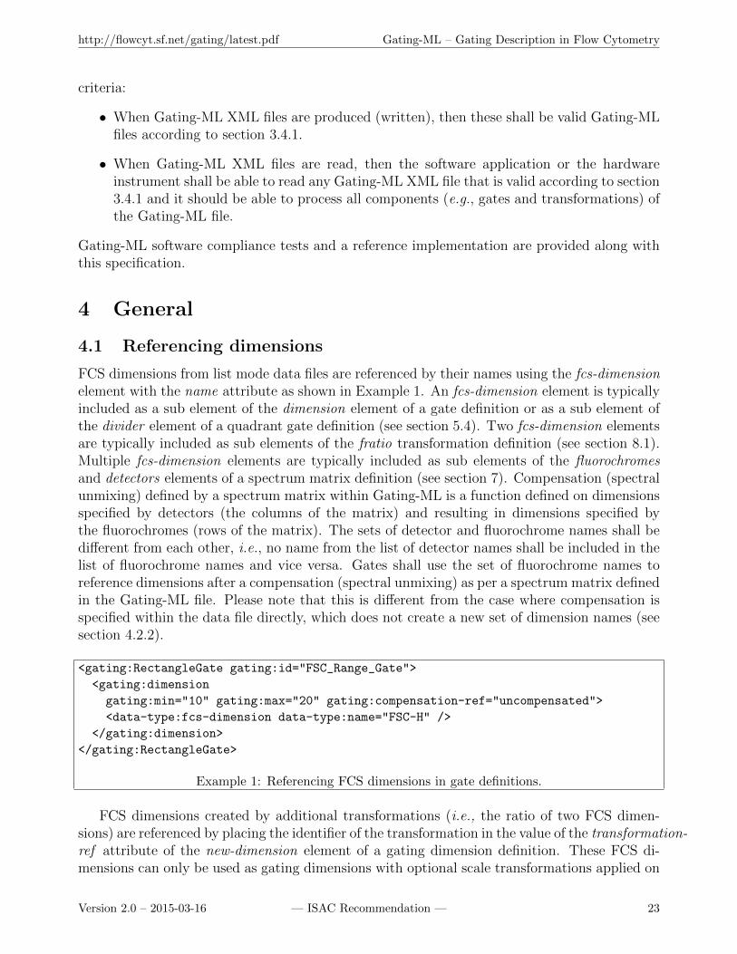
FCS dimensions from list mode data files are referenced by their names using the fcs-dimensionelement with the name attribute as shown in Example 1. An fcs-dimension element is typicallyincluded as a sub element of the dimension element of a gate definition or as a sub element ofthe divider element of a quadrant gate definition (see section 5.4). Two fcs-dimension elementsare typically included as sub elements of the fratio transformation definition (see section 8.1).Multiple fcs-dimension elements are typically included as sub elements of the fluorochromesand detectors elements of a spectrum matrix definition (see section 7). Compensation (spectralunmixing) defined by a spectrum matrix within Gating-ML is a function defined on dimensionsspecified by detectors (the columns of the matrix) and resulting in dimensions specified bythe fluorochromes (rows of the matrix). The sets of detector and fluorochrome names shall bedifferent from each other, i.e., no name from the list of detector names shall be included in thelist of fluorochrome names and vice versa. Gates shall use the set of fluorochrome names toreference dimensions after a compensation (spectral unmixing) as per a spectrum matrix definedin the Gating-ML file. Please note that this is different from the case where compensation isspecified within the data file directly, which does not create a new set of dimension names (seesection 4.2.2).
<gating:RectangleGate gating:id="FSC_Range_Gate">
<gating:dimension
gating:min="10" gating:max="20" gating:compensation-ref="uncompensated">
<data-type:fcs-dimension data-type:name="FSC-H" />
</gating:dimension>
</gating:RectangleGate>
Example 1: Referencing FCS dimensions in gate definitions.
FCS dimensions created by additional transformations (i.e., the ratio of two FCS dimen-sions) are referenced by placing the identifier of the transformation in the value of the transformation-ref attribute of the new-dimension element of a gating dimension definition. These FCS di-mensions can only be used as gating dimensions with optional scale transformations applied on
Version 2.0 – 2015-03-16 — ISAC Recommendation — 23
http://flowcyt.sf.net/gating/latest.pdf Gating-ML – Gating Description in Flow Cytometry
top of these; however, they cannot be used within the ratio transformation, neither as detectorsor fluorochromes of a spectrum matrix definition. Example 2 demonstrates how a ratio of twoFCS dimensions can be reused in a range gate definition. Currently, a parametrized ratio oftwo FCS dimensions is the only supported “additional” transformation.
<gating:RectangleGate gating:id="Range_Gate_On_Ratio">
<gating:dimension gating:min="5" gating:max="20" gating:compensation-ref="FCS">
<data-type:new-dimension data-type:transformation-ref="myRatio" />
</gating:dimension>
</gating:RectangleGate>
<transforms:transformation transforms:id="myRatio">
<transforms:fratio transforms:A="1" transforms:B="0" transforms:C="0" >
<data-type:fcs-dimension data-type:name="FL1-A" />
<data-type:fcs-dimension data-type:name="FL2-A" />
</transforms:fratio>
</transforms:transformation>
Example 2: Referencing the ratio of two FCS dimensions in gate definitions.
The dimension names (and transformation identifiers) are case sensitive (i.e., “FSC-H” and“Fsc-H” are two different FCS dimension names). In case the corresponding list mode datafile is an FCS [2] file, the name is the value of the $PnN keywords. In case of other list modedata files, the name of the FCS dimension is format-specific identification of the dimension.Specifically, in case of list-mode data files stored in NetCDF [17] files, the name of a dimensionis the “variable name” in the NetCDF file. In case of tabular-based list mode data files with rowscorresponding to events and columns corresponding to FCS dimensions (e.g., CSV files [18],MS Excel spreadsheets, etc.), the name of a dimension is the heading of the particular datacolumn.
4.2 FCS dimensions and transformations
Gates are applicable on list mode data files either directly or after a transformation. Theseoptions are briefly introduced below and demonstrated in the work flow diagram shown inFigure 5.
4.2.1 Gates applicable directly on uncompensated list mode data files
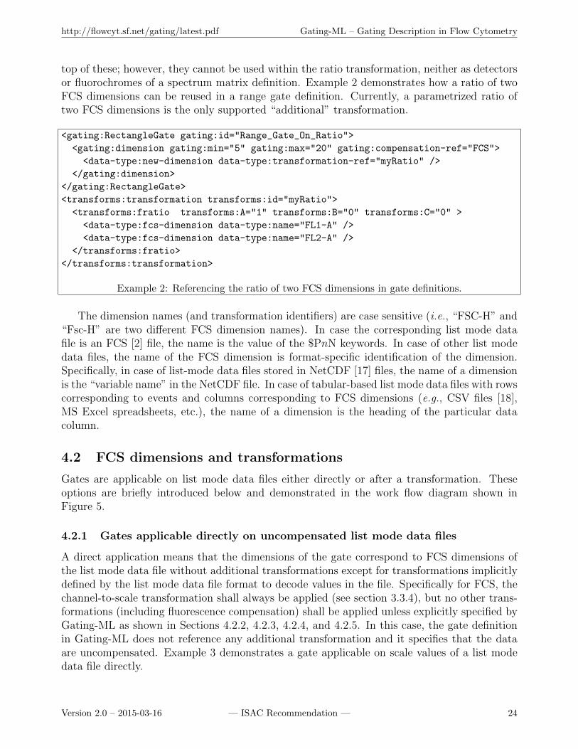
A direct application means that the dimensions of the gate correspond to FCS dimensions ofthe list mode data file without additional transformations except for transformations implicitlydefined by the list mode data file format to decode values in the file. Specifically for FCS, thechannel-to-scale transformation shall always be applied (see section 3.3.4), but no other trans-formations (including fluorescence compensation) shall be applied unless explicitly specified byGating-ML as shown in Sections 4.2.2, 4.2.3, 4.2.4, and 4.2.5. In this case, the gate definitionin Gating-ML does not reference any additional transformation and it specifies that the dataare uncompensated. Example 3 demonstrates a gate applicable on scale values of a list modedata file directly.
Version 2.0 – 2015-03-16 — ISAC Recommendation — 24

http://flowcyt.sf.net/gating/latest.pdf Gating-ML – Gating Description in Flow Cytometry
Figure 5: Work flow of data transformations prior to the application of a gate.
4.2.2 Gates applicable on compensated data
If a gate is supposed to be applied on compensated data, then the compensation shall be refer-enced as part of the gate definition. There are two options where the compensation definitionmay reside:
1. The compensation definition may be encoded directly in the same list mode data file asthe data (event values). Typically, this may be by means of the $SPILLOVER keywords inFCS version 3.1 [2], $COMP keywords in FCS version 3.0 [7] (rarely used) or some customkeywords, such as the SPILL keywords as introduced by Becton, Dickinson and Company.
Version 2.0 – 2015-03-16 — ISAC Recommendation — 25
http://flowcyt.sf.net/gating/latest.pdf Gating-ML – Gating Description in Flow Cytometry
<gating:PolygonGate gating:id="Example_P1">
<gating:dimension gating:compensation-ref="uncompensated">
<data-type:fcs-dimension data-type:name="FSC-H" />
</gating:dimension>
<gating:dimension gating:compensation-ref="uncompensated">
<data-type:fcs-dimension data-type:name="SSC-H" />
</gating:dimension>
<gating:vertex>
<gating:coordinate data-type:value="100" />
<gating:coordinate data-type:value="100" />
</gating:vertex>
<!-- Definition of other vertices would follow -->
...
</gating:PolygonGate>
Example 3: Gate applicable directly on uncompensated scale values of a list mode data file.
The Gating-ML definition of a dimension that is supposed to reference data compensatedas prescribed by related list mode data file shall contain a compensation-ref attribute setto the value “FCS” as shown in Example 4. Names of the FCS dimensions do not changewith compensation according to the list mode data file, i.e., in case the corresponding listmode data file is an FCS file then gates should still use the values of the $PnN keywordsto reference gating dimensions.
2. The compensation definition may be part of the Gating-ML file. In this case, the com-pensation is defined by a spectrum matrix as specified in section 7. The Gating-MLdefinition of a dimension that is supposed to reference data compensated according tothe spectrum matrix defined in Gating-ML shall contain a compensation-ref attribute setto the value of the identifier of the spectrum matrix as shown in Example 5. Compen-sation (spectral unmixing) defined by a spectrum matrix within Gating-ML is a functiondefined on dimensions specified by detectors (columns) of the matrix and resulting indimensions specified by the fluorochromes (rows) of the matrix. The sets of detectorand fluorochrome names shall be different from each other, i.e., no name from the list ofdetector names shall be included in the list of fluorochrome names and vice versa. Forthese cases, gates shall use the set of fluorochrome (row) names to reference compensated(un-mixed) dimensions as per such a spectrum matrix (Example 6).
4.2.3 Gates applicable on data on transformed scales
As mentioned in section 2.3.1, further scale transformations are commonly performed to pro-vide more complete, appropriate, and readily interpretable data representations, or to achieveoptimal display of the data. If a gate uses a transformed scale (e.g., the gate is drawn whiledata is displayed on a transformed scale), then the transformation shall be recorded in theGating-ML (see section 6) and referenced in the appropriate gating dimension definition usingthe transformation-ref attribute as shown in Example 7. These transformations may be com-bined with both compensated and uncompensated data using the compensation-ref attribute
Version 2.0 – 2015-03-16 — ISAC Recommendation — 26
http://flowcyt.sf.net/gating/latest.pdf Gating-ML – Gating Description in Flow Cytometry
<gating:PolygonGate gating:id="Example_P2">
<gating:dimension gating:compensation-ref="FCS">
<data-type:fcs-dimension data-type:name="FL1-H" />
</gating:dimension>
<gating:dimension gating:compensation-ref="FCS">
<data-type:fcs-dimension data-type:name="FL2-H" />
</gating:dimension>
<!-- Definition of gate vertices would follow -->
...
</gating:PolygonGate>
Example 4: Gate applicable on scale values compensated as defined in the FCS file.
<transforms:spectrumMatrix transforms:id="my_spill_1">
<transforms:fluorochromes>
<data-type:fcs-dimension data-type:name="FITC"/>
<data-type:fcs-dimension data-type:name="PE"/>
</transforms:fluorochromes>
<transforms:detectors>
<data-type:fcs-dimension data-type:name="FL1-H"/>
<data-type:fcs-dimension data-type:name="FL2-H"/>
</transforms:detectors>
<!-- Definition of the matrix would continue here -->
...
</transforms:spectrumMatrix>
<gating:PolygonGate gating:id="Example_P3">
<gating:dimension gating:compensation-ref="my_spill_1">
<data-type:fcs-dimension data-type:name="FITC" />
</gating:dimension>
<gating:dimension gating:compensation-ref="my_spill_1">
<data-type:fcs-dimension data-type:name="PE" />
</gating:dimension>
<!-- Definition of gate vertices would follow -->
...
</gating:PolygonGate>
Example 5: Gate applicable on scale values compensated as defined in Gating-ML.
as described in sections 4.2.1 and 4.2.2, and they may also be applied on dimensions createdby “additional” transformations, i.e., on the ratio of two FCS dimensions.
4.2.4 Gates applicable on the ratio of two FCS dimensions
Gates may be applied on new FCS dimensions created as the ratio of two FCS dimensions aspreviously described in section 4.1. These newly created FCS dimensions shall be referenced byplacing the identifier of the source ratio transformation in the value of the transformation-refattribute of the new-dimension element of a gating dimension definition (see also Example 2).
Version 2.0 – 2015-03-16 — ISAC Recommendation — 27

http://flowcyt.sf.net/gating/latest.pdf Gating-ML – Gating Description in Flow Cytometry
<transforms:spectrumMatrix transforms:id="my_spectrum_1">
<transforms:fluorochromes>
<data-type:fcs-dimension data-type:name="FITC"/>
<data-type:fcs-dimension data-type:name="PE"/>
</transforms:fluorochromes>
<transforms:detectors>
<data-type:fcs-dimension data-type:name="FL1-H"/>
<data-type:fcs-dimension data-type:name="FL2-H"/>
<data-type:fcs-dimension data-type:name="FL3-H"/>
</transforms:detectors>
<!-- Definition of the matrix would continue here -->
...
</transforms:spectrumMatrix>
<gating:PolygonGate gating:id="Example_P4">
<gating:dimension gating:compensation-ref="my_spectrum_1">
<data-type:fcs-dimension data-type:name="FITC" />
</gating:dimension>
<gating:dimension gating:compensation-ref="my_spectrum_1">
<data-type:fcs-dimension data-type:name="PE" />
</gating:dimension>
<!-- Definition of gate vertices would follow -->
...
</gating:PolygonGate>
Example 6: Gate applicable on scale values un-mixed as defined in Gating-ML.
<transforms:transformation transforms:id="my_logicle_1">
<transforms:logicle transforms:T="10000" transforms:M="4.5"
transforms:W="0.5" transforms:A="0" />
</transforms:transformation>
<gating:PolygonGate gating:id="Example_P5">
<gating:dimension gating:transformation-ref="my_logicle_1"
gating:compensation-ref="FCS">
<data-type:fcs-dimension data-type:name="FL4-H" />
</gating:dimension>
<gating:dimension gating:transformation-ref="my_logicle_1"
gating:compensation-ref="FCS">
<data-type:fcs-dimension data-type:name="FL5-H" />
</gating:dimension>
<!-- Definition of gate vertices would follow -->
...
</gating:PolygonGate>
Example 7: Gate applicable on data on a Logicle scale.
Similarly to referencing regular FCS dimensions, the ratio may be referenced as compen-
Version 2.0 – 2015-03-16 — ISAC Recommendation — 28

http://flowcyt.sf.net/gating/latest.pdf Gating-ML – Gating Description in Flow Cytometry
sated or uncompensated by specifying the compensation-ref attribute as described in sections4.2.1 and 4.2.2. However, if compensation is specified, then it shall be applied on the sourceFCS dimensions (i.e., dimensions from the list mode data file, such as FL1, FL2, etc.) priorto the calculation of the ratio as shown in Figure 5. In Example 2 above, one would firstapply the implicit channel-to-scale transformation on the FL1-A and FL2-A FCS dimensions(if applicable based on how data are captured in the list mode data file, see section 3.3.4), thencompensate these dimensions as prescribed by the list mode data file (e.g., the $SPILLOVER or$COMP keywords, see section 4.2.2), then calculate the ratio of compensated FL1-A and FL2-H,and then apply the gate.
4.2.5 Gates applicable on scaled ratio of two FCS dimensions
As described in section 4.2.4, gates may be applied on the ratio of two FCS dimensions. Thismay be referenced as compensated or uncompensated. In addition, the ratio of two FCSdimensions may be scaled using one of the scale transformations listed in section 6.
In the situation described in Example 8, one would first apply the implicit channel-to-scaletransformation on the FL3-A and FL4-A FCS dimensions (if applicable based on how dataare captured in the list mode data file, see section 3.3.4), then compensate these dimensionsas prescribed by the list mode data file (e.g., the $SPILLOVER or $COMP keywords, see section4.2.2), then calculate the ratio of compensated FL3-A and FL4-A, then scale the result usingthe prescribed logarithmic transformation, and then finally apply the gate.
<gating:RectangleGate gating:id="Range_Gate_On_Scaled_Ratio">
<gating:dimension gating:min="0.5"
gating:compensation-ref="FCS" gating:transformation-ref="myRatioLog">
<data-type:new-dimension data-type:transformation-ref="myRatio" />
</gating:dimension>
</gating:RectangleGate>
<transforms:transformation transforms:id="myRatio">
<transforms:fratio transforms:A="1" transforms:B="0" transforms:C="0" >
<data-type:fcs-dimension data-type:name="FL3-A" />
<data-type:fcs-dimension data-type:name="FL4-A" />
</transforms:fratio>
</transforms:transformation>
<transforms:transformation transforms:id="myRatioLog">
<transforms:flog transforms:T="100" transforms:M="4" />
</transforms:transformation>
Example 8: Referencing scaled ratio of two FCS dimensions in a gate definition.
4.3 Results of gating operations
The gating operation returns the set of events within the gate. The actual values of these eventsshall not change as a side effect of any gating operation. If a gate definition includes compensa-tion, then the compensation should be used if the gating results are to be visualized graphically.Similarly, if a gate definition includes a scale transformation, then scale transformation should
Version 2.0 – 2015-03-16 — ISAC Recommendation — 29
http://flowcyt.sf.net/gating/latest.pdf Gating-ML – Gating Description in Flow Cytometry
be used if the gating results are to be visualized graphically. Internally, the analytical softwaremay also want to keep compensated and scaled values for performance purposes.
4.4 Hierarchical gating and gating strategy description
A gate definition can include an optional parent id attribute that can be used to reference aparent gate by its identifier. A gate is supposed to be applied on the whole population unlessthe parent id attribute is used. If the parent id attribute is specified, then the gate is supposedto be applied on a population defined by its parent gate, which may be used to encode thegating strategy (hierarchy). Let G be a gate with a specified parent gate Gp, and let G′ be agate defined the same way as gate G except for the parent id attribute – gate G′ does not defineany parent gate. The result of applying a gate G is the intersection of the result of applyingthe parent gate Gp with the gate G′. Same results (in terms of events filtered by the gate) maybe obtained by creating a Boolean And gate. However, a Boolean And gate does not capturethe semantic of a parent gate or the gating hierarchy.
4.5 Gating-ML file structure
A Gating-ML file is a valid XML [3] file that corresponds to the Gating-ML.v2.0.xsd XMLschema and conforms to the validity conditions as described in Section 3.4.1. The Gating-MLXML schema specifies the http://www.isac-net.org/std/Gating-ML/v2.0/gating targetnamespace. Gating-ML is the main element of a Gating-ML file. Child elements describeindividual gates, transformations, and spectrum matrices. Example 9 shows an example of theheader of a Gating-ML XML file.
Please note that you may also use a local path (formatted as URI/URL) to reference XMLschema files in the schemaLocation attribute in order to accelerate the XML validation process.Definition of gates, transformations, spectrum matrices, and custom elements is included withinthe Gating-ML element as described further in this specification. The main Gating-ML elementmay have one or more of the following sub elements in any order:
RectangleGate – description of an n dimensional rectangular gate (including a range gateand hyper-rectangular regions) as described in section 5.1.
PolygonGate – description of a two dimensional polygon gate as described in section 5.2.
EllipsoidGate – description of an n dimensional ellipsoid gate (including 2 dimensional ellipsegate) as described in section 5.3.
QuadrantGate – description of a quadrant gate as described in section 5.4.
BooleanGate – description of a Boolean gate as described in section 5.5.
transformation – description of a scale transformation as described in section 6 or a newparameter creation as described in section 8.
spectrumMatrix – description of a spectrum (spillover) matrix as described in section 7.
custom info – additional custom information as described in section 4.8.
Version 2.0 – 2015-03-16 — ISAC Recommendation — 30
http://flowcyt.sf.net/gating/latest.pdf Gating-ML – Gating Description in Flow Cytometry
<?xml version="1.0" encoding="UTF-8"?>
<gating:Gating-ML xmlns:xsi="http://www.w3.org/2001/XMLSchema-instance"
xmlns:gating="http://www.isac-net.org/std/Gating-ML/v2.0/gating"
xmlns:transforms="http://www.isac-net.org/std/Gating-ML/v2.0/transformations"
xmlns:data-type="http://www.isac-net.org/std/Gating-ML/v2.0/datatypes"
xsi:schemaLocation="
http://www.isac-net.org/std/Gating-ML/v2.0/gating
http://flowcyt.sourceforge.net/gating/2.0/xsd/Gating-ML.v2.0.xsd
http://www.isac-net.org/std/Gating-ML/v2.0/transformations
http://flowcyt.sourceforge.net/gating/2.0/xsd/Transformations.v2.0.xsd
http://www.isac-net.org/std/Gating-ML/v2.0/datatypes
http://flowcyt.sourceforge.net/gating/2.0/xsd/DataTypes.v2.0.xsd">
<!-- Description of gates, transformations, spectrum matrices, etc. -->
<gating:RectangleGate gating:id="Example_R1">
<gating:dimension gating:min="100" gating:compensation-ref="uncompensated">
<data-type:fcs-dimension data-type:name="FSC-H"/>
</gating:dimension>
</gating:RectangleGate>
</gating:Gating-ML>
Example 9: Gating-ML XML file demonstrating proper header definition.
4.6 Gates overview
Gating-ML element is the main element of a Gating-ML file. The following sub elementsmay be included to define various types of gates: RectangleGate, PolygonGate, EllipsoidGate,QuadrantGate and BooleanGate.
The XML schemas define an abstract gate type AbstractGate Type that is used as an ex-tension base for all the other types of gates. This design allows all gate types to inherit the idattribute that is used for identification and reference purposes, and the parent id attribute thatallows for description of hierarchical gating and gating strategies as described in section 4.4.
4.7 Scale transformations overview
Gating-ML allows for a scale transformation description within a transformation element (subelement of the main Gating-ML element). The transformation element shall include an idattribute to assign a unique identifier to the transformation. In addition, the boundMin andboundMax attributes may be present. If present, these attributes define the boundaries of thetransformation as specified in section 6.1. The transformation description follows within thetransformation element as one of the flin (parametrized linear), flog (parametrized logarithmic),fasinh (parametrized inverse hyperbolic sine), logicle and hyperlog.
Design goals of the specification of the logarithmic and log-like transformations are to makethese comprehensible to the end users, i.e., scientists, and also to ease the burden to im-plementers. To achieve the latter, these transformations are designed so that they map anappropriate range of data values onto a standard unit display interval [0,1].
Version 2.0 – 2015-03-16 — ISAC Recommendation — 31
http://flowcyt.sf.net/gating/latest.pdf Gating-ML – Gating Description in Flow Cytometry
To make the transformations comprehensible, they are defined in terms of a consistentparameterization that is closely related to the user experience. The top of scale value T is alwaysmapped to the value 1. In addition, the logarithmic and log-like transforms are parametrizedby M , the number of decades of data range mapped onto the unit display interval by theLogarithmic transform. The log-like scales are also parametrized by W and A, which arecommensurate with decades on the scale although they do not represent ten fold changes indata value. W controls the degree of linearization for the Logicle and Hyperlog transforms. Theparameter A specifies an additional range of negative data values that are to be brought onscale. For the Logicle and Hyperlog transforms, this is in addition to what is already broughton scale by W and should generally not be needed. The Logicle, Hyperlog, and parametrizedinverse hyperbolic sine transforms with A = 0 will all behave like the logarithmic transformwith the same values of T and M for large data values.
This choice of parameters also leads to a sensible fall back strategy when software does notimplement a particular transform. For example, if the Logicle transform is not available, thena Hyperlog transform with the same parameters should be a reasonable alternative, and viceversa (see tables 8 and 9). Figure 6 shows a comparison of the parametrized logarithmic andthe supported log-like scale transformations with T = 1000, M = 4.5, W = 1 and A = 0(W and A set where applicable only). As you can see, all transformations are very close toeach other for large data values. In the low data range (zoomed-in in the two sub figures),the parametrized inverse hyperbolic sine, Logicle, and Hyperlog transforms show a “linear-like” behavior around zero and “extend” the scale to the negative data range. Unlike theparametrized inverse hyperbolic sine, the Logicle and Hyperlog transforms allow the width ofthe linearization region to be controlled independently from the logarithmic character for largedata values.
The effect of increasing A is shown in Figure 7, which demonstrates the same transformationswith T = 1000, W = 1, and M = 5 for the parametrized logarithmic, while M = 4 for theother transformations since these also include an additional negative decade (A = 1).
4.8 Additional custom information
Gating-ML allows for a custom info element to capture additional vendor specific informa-tion within Gating-ML. This element may be placed at the top level as a sub element of themain Gating-ML element as demonstrated in Example 10, or as the first sub element of thespectrumMatrix element (for information related to the compensation definition), transforma-tion element (for information related to a scale transformation), or any of the gate definitionelements (for information related to a particular gate definition, see section 5).
In addition, any gate, transformation or spectrum (spillover) matrix element may includecustom attributes as permitted by the XML schemas. This is also demonstrated by examplesaccompanying this specification. Custom information may be used to encode additional optionalinformation (e.g., visual properties of a drawn gate), but shall not be used as proprietaryalternative to communicate aspects standardized by this specification.
Version 2.0 – 2015-03-16 — ISAC Recommendation — 32
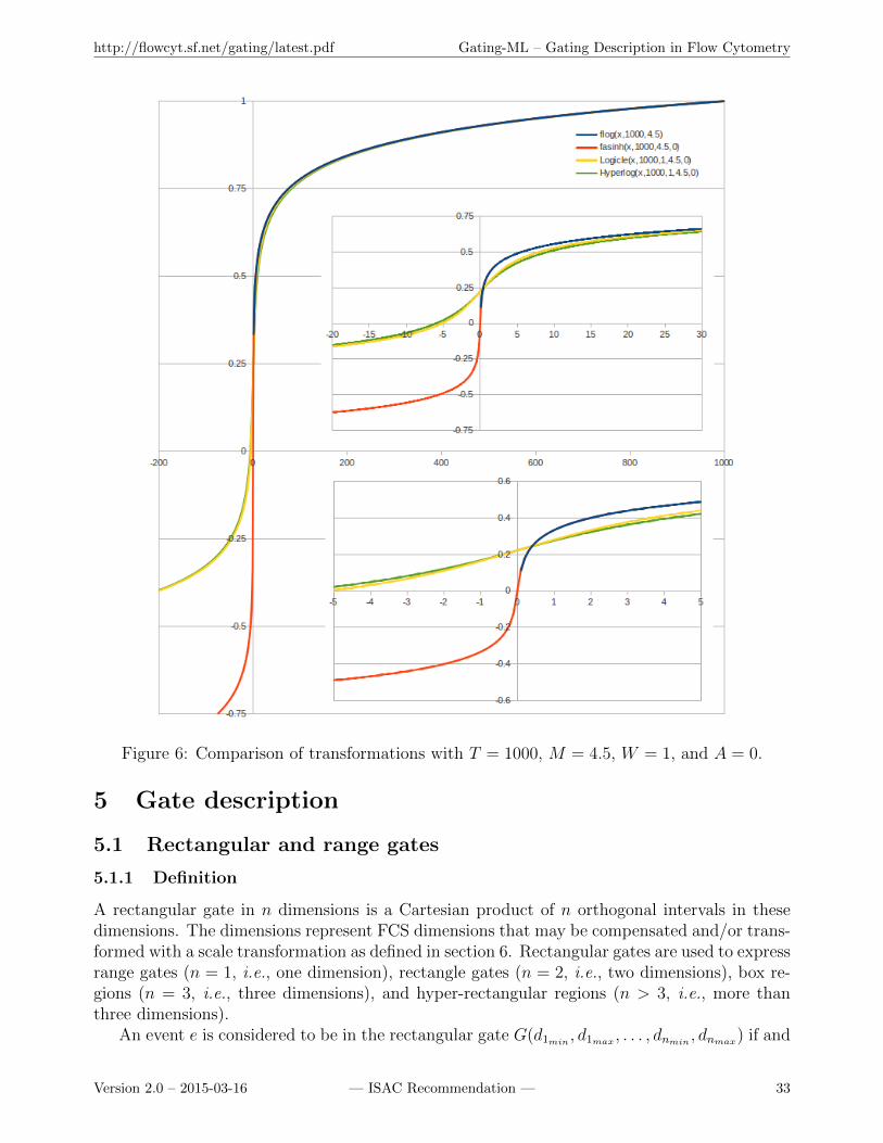
http://flowcyt.sf.net/gating/latest.pdf Gating-ML – Gating Description in Flow Cytometry
Figure 6: Comparison of transformations with T = 1000, M = 4.5, W = 1, and A = 0.
5 Gate description
5.1 Rectangular and range gates
5.1.1 Definition
A rectangular gate in n dimensions is a Cartesian product of n orthogonal intervals in thesedimensions. The dimensions represent FCS dimensions that may be compensated and/or trans-formed with a scale transformation as defined in section 6. Rectangular gates are used to expressrange gates (n = 1, i.e., one dimension), rectangle gates (n = 2, i.e., two dimensions), box re-gions (n = 3, i.e., three dimensions), and hyper-rectangular regions (n > 3, i.e., more thanthree dimensions).
An event e is considered to be in the rectangular gate G(d1min, d1max , . . . , dnmin
, dnmax) if and
Version 2.0 – 2015-03-16 — ISAC Recommendation — 33
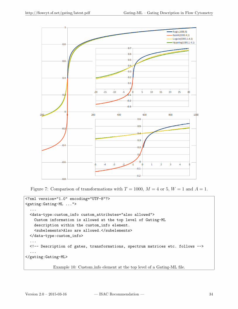
http://flowcyt.sf.net/gating/latest.pdf Gating-ML – Gating Description in Flow Cytometry
Figure 7: Comparison of transformations with T = 1000, M = 4 or 5, W = 1 and A = 1.
<?xml version="1.0" encoding="UTF-8"?>
<gating:Gating-ML ...">
...
<data-type:custom_info custom_attributes="also allowed">
Custom information is allowed at the top level of Gating-ML
description within the custom_info element.
<subelements>Also are allowed.</subelements>
</data-type:custom_info>
...
<!-- Description of gates, transformations, spectrum matrices etc. follows -->
...
</gating:Gating-ML>
Example 10: Custom info element at the top level of a Gating-ML file.
Version 2.0 – 2015-03-16 — ISAC Recommendation — 34
http://flowcyt.sf.net/gating/latest.pdf Gating-ML – Gating Description in Flow Cytometry
only if for each dimension di, i ∈ N, 1 ≤ i ≤ n of the Gate G dimin≤ e(di) < dimax , where dimin
is the value of the min attribute of the dimension di, dimax is the value of the max attribute ofthe dimension di, and e(di) is the scale value of the event e in FCS dimension di (which maybe compensated or additionally transformed). The intervals are treated as half open with weakinequality of the lower bound and strict inequality of the upper bound so that a set of rectanglegates that covers the data space will sum properly with no missing or duplicated events.
5.1.2 Syntax specification
Rectangular gates shall be specified by the RectangleGate element as follows:
(a) The id attribute shall be used to identify the gate for further referencing purposes, e.g., asdescribed in sections 4.4 and 5.5.
(b) The parent id attribute may be used to reference a parent gate as described in section 4.4.
(c) A custom info element may be placed at the beginning of the RectangleGate element. Thecustom info element may contain any additional custom information related to this gate;the format of this element (i.e., its attributes, sub elements, etc.) is not constrained bythis specification as long as the document remains a valid XML.
(d) At least one dimension shall be described by a dimension element placed either as the firstsub element of the RectangleGate element or right after the custom info element if thecustom info element is used. The maximum number of dimension elements is unbounded.
(e) Each dimension element shall specify compensation by including the compensation-ref at-tribute as specified in section 4.2. The value of this attribute may be one of the following:FCS, uncompensated, or the identifier of a spectrum matrix defined within the Gating-MLfile.
(f) Each dimension element may use the transformation-ref attribute to reference a scaletransformation. If used, the value of this attribute shall contain the identifier of a scaletransformation defined within this Gating-ML file (see section 4.2.3).
(g) Each dimension element shall specify a range by the min or max attributes of the dimensionelement; at least one of the min or max attributes shall be present. If they are bothspecified, the value of the min attribute shall be less than the value of the max attribute.If the max attribute is absent, then the range in this dimension is considered as [min,∞). Ifthe min attribute is absent, then the range in this dimension is considered as [−∞,max). Ifboth the min and max attributes are present, then the range in this dimension is consideredas [min,max).
(h) Each dimension element shall reference a dimension as described in section 4.1, i.e., byincluding an fcs-dimension element or a new-dimension element. The same FCS dimensionor new dimension may not be used more than once within the gate definition.
Version 2.0 – 2015-03-16 — ISAC Recommendation — 35
http://flowcyt.sf.net/gating/latest.pdf Gating-ML – Gating Description in Flow Cytometry
5.1.3 Validity conditions
A rectangular gate definition is valid if and only if:
(a) It is valid according to the XML schema.
(b) If used, the parent id attribute does not introduce any circular dependency (see also sections3.3.6, 3.3.7 and 3.4.1).
(c) The gating dimensions are different from one another, i.e., the values of the name attributesare unique among all fcs-dimension elements (if used) in the gate definition, and the valuesof the transformation-ref attributes are unique among all new-dimension elements (if used)in the gate definition.
(d) The value of the compensation-ref attribute of each dimension element equals to eitherFCS, uncompensated, or an identifier of a spectrum matrix defined within the Gating-MLfile.
(e) If used, the value of the transformation-ref attribute of the dimension element shall containan identifier of a scale transformation defined within the same Gating-ML file.
(f) At least one of the min and max attributes is specified for each dimension element.
(g) If both the min and the max attributes are specified, then the value of the min attributeshall be less than the value of the max attribute.
(h) If used, the value of the transformation-ref attribute of the new-dimension element shallcontain an identifier of a transformation that creates a new dimension, i.e., an identifier ofa parametrized ratio transformation.
5.1.4 Examples
(a) Example 11 demonstrates the definition of a range gate that includes events with scalevalues of the FCS-H dimension from the [100, 250) interval. Visual representation of thisgate is shown in Figure 8. Uncompensated values are used for the purpose of this gate.
<gating:RectangleGate gating:id="Range_FCS_b_100_250">
<gating:dimension gating:min="100" gating:max="250"
gating:compensation-ref="uncompensated">
<data-type:fcs-dimension data-type:name="FSC-H" />
</gating:dimension>
</gating:RectangleGate>
Example 11: Range gate definition.
(b) Example 12 demonstrates the definition of an open range gate that includes events withscale values of the FCS-H dimension greater than or equal to 100. Visual representation ofthis gate is shown in Figure 9. Values compensated as prescribed by the list mode data file(see section 4.2.2 for more details) are used for the purpose of this gate. In this particular
Version 2.0 – 2015-03-16 — ISAC Recommendation — 36
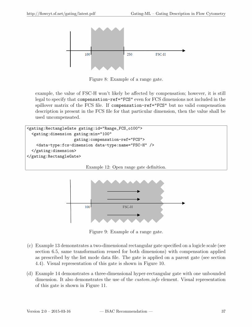
http://flowcyt.sf.net/gating/latest.pdf Gating-ML – Gating Description in Flow Cytometry
Figure 8: Example of a range gate.
example, the value of FSC-H won’t likely be affected by compensation; however, it is stilllegal to specify that compensation-ref="FCS" even for FCS dimensions not included in thespillover matrix of the FCS file. If compensation-ref="FCS" but no valid compensationdescription is present in the FCS file for that particular dimension, then the value shall beused uncompensated.
<gating:RectangleGate gating:id="Range_FCS_o100">
<gating:dimension gating:min="100"
gating:compensation-ref="FCS">
<data-type:fcs-dimension data-type:name="FSC-H" />
</gating:dimension>
</gating:RectangleGate>
Example 12: Open range gate definition.
Figure 9: Example of a range gate.
(c) Example 13 demonstrates a two-dimensional rectangular gate specified on a logicle scale (seesection 6.5, same transformation reused for both dimensions) with compensation appliedas prescribed by the list mode data file. The gate is applied on a parent gate (see section4.4). Visual representation of this gate is shown in Figure 10.
(d) Example 14 demonstrates a three-dimensional hyper-rectangular gate with one unboundeddimension. It also demonstrates the use of the custom info element. Visual representationof this gate is shown in Figure 11.
Version 2.0 – 2015-03-16 — ISAC Recommendation — 37
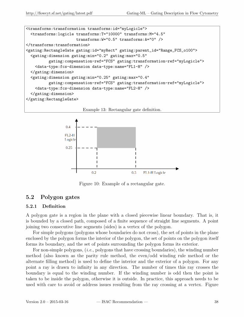
http://flowcyt.sf.net/gating/latest.pdf Gating-ML – Gating Description in Flow Cytometry
<transforms:transformation transforms:id="myLogicle">
<transforms:logicle transforms:T="10000" transforms:M="4.5"
transforms:W="0.5" transforms:A="0" />
</transforms:transformation>
<gating:RectangleGate gating:id="myRect" gating:parent_id="Range_FCS_o100">
<gating:dimension gating:min="0.2" gating:max="0.5"
gating:compensation-ref="FCS" gating:transformation-ref="myLogicle">
<data-type:fcs-dimension data-type:name="FL1-H" />
</gating:dimension>
<gating:dimension gating:min="0.25" gating:max="0.4"
gating:compensation-ref="FCS" gating:transformation-ref="myLogicle">
<data-type:fcs-dimension data-type:name="FL2-H" />
</gating:dimension>
</gating:RectangleGate>
Example 13: Rectangular gate definition.
Figure 10: Example of a rectangular gate.
5.2 Polygon gates
5.2.1 Definition
A polygon gate is a region in the plane with a closed piecewise linear boundary. That is, itis bounded by a closed path, composed of a finite sequence of straight line segments. A pointjoining two consecutive line segments (sides) is a vertex of the polygon.
For simple polygons (polygons whose boundaries do not cross), the set of points in the planeenclosed by the polygon forms the interior of the polygon, the set of points on the polygon itselfforms its boundary, and the set of points surrounding the polygon forms its exterior.
For non-simple polygons, (i.e., polygons that have crossing boundaries), the winding numbermethod (also known as the parity rule method, the even/odd winding rule method or thealternate filling method) is used to define the interior and the exterior of a polygon. For anypoint a ray is drawn to infinity in any direction. The number of times this ray crosses theboundary is equal to the winding number. If the winding number is odd then the point istaken to be inside the polygon, otherwise it is outside. In practice, this approach needs to beused with care to avoid or address issues resulting from the ray crossing at a vertex. Figure
Version 2.0 – 2015-03-16 — ISAC Recommendation — 38
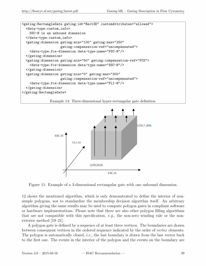
http://flowcyt.sf.net/gating/latest.pdf Gating-ML – Gating Description in Flow Cytometry
<gating:RectangleGate gating:id="Rect3D" customAttributes="allowed">
<data-type:custom_info>
SSC-H is an unbound dimension
</data-type:custom_info>
<gating:dimension gating:min="100" gating:max="250"
gating:compensation-ref="uncompensated">
<data-type:fcs-dimension data-type:name="FSC-H"/>
</gating:dimension>
<gating:dimension gating:min="50" gating:compensation-ref="FCS">
<data-type:fcs-dimension data-type:name="SSC-H"/>
</gating:dimension>
<gating:dimension gating:min="0" gating:max="300"
gating:compensation-ref="uncompensated">
<data-type:fcs-dimension data-type:name="FL1-H"/>
</gating:dimension>
</gating:RectangleGate>
Example 14: Three-dimensional hyper-rectangular gate definition.
Figure 11: Example of a 3-dimensional rectangular gate with one unbound dimension.
12 shows the mentioned algorithm, which is only demonstrated to define the interior of non-simple polygons, not to standardize the membership decision algorithm itself. An arbitraryalgorithm giving the same results may be used to compute polygon gates in compliant softwareor hardware implementations. Please note that there are also other polygon filling algorithmsthat are not compatible with this specification, e.g., the non-zero winding rule or the non-exterior method [19–21].
A polygon gate is defined by a sequence of at least three vertices. The boundaries are drawnbetween consequent vertices in the ordered sequence indicated by the order of vertex elements.The polygon is automatically closed, i.e., the last boundary is drawn from the last vertex backto the first one. The events in the interior of the polygon and the events on the boundary are
Version 2.0 – 2015-03-16 — ISAC Recommendation — 39

http://flowcyt.sf.net/gating/latest.pdf Gating-ML – Gating Description in Flow Cytometry
Figure 12: Winding number method used to determine the interior of non-simple polygons.
considered to be in the gate (i.e., the boundary is considered as inclusive).
5.2.2 Syntax specification
Polygon gates shall be specified by the PolygonGate element as follows:
(a) The id attribute shall be used to identify the gate for further referencing purposes, e.g., asdescribed in sections 4.4 and 5.5.
(b) The parent id attribute may be used to reference a parent gate as described in section 4.4.
(c) A custom info element may be placed at the beginning of the PolygonGate element. Thecustom info element may contain any additional custom information related to this gate;the format of this element (i.e., its attributes, sub elements, etc.) is not constrained bythis specification as long as the document remains a valid XML.
(d) Two dimensions shall be described by two dimension elements placed as at the beginning ofthe PolygonGate element or right after the custom info element if the custom info elementis used.
(e) Each dimension element shall specify compensation by including the compensation-ref at-tribute as specified in section 4.2. The value of this attribute may be one of the following:FCS, uncompensated, or the identifier of a spectrum matrix defined within the Gating-MLfile.
Version 2.0 – 2015-03-16 — ISAC Recommendation — 40
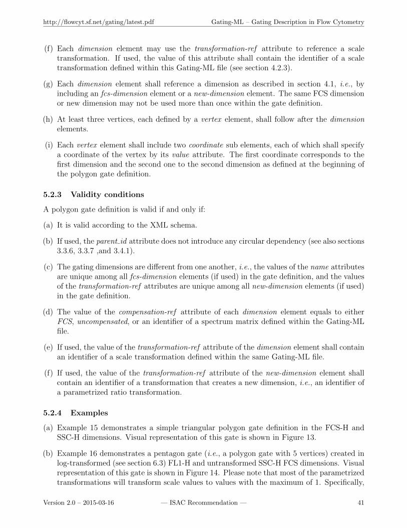
http://flowcyt.sf.net/gating/latest.pdf Gating-ML – Gating Description in Flow Cytometry
(f) Each dimension element may use the transformation-ref attribute to reference a scaletransformation. If used, the value of this attribute shall contain the identifier of a scaletransformation defined within this Gating-ML file (see section 4.2.3).
(g) Each dimension element shall reference a dimension as described in section 4.1, i.e., byincluding an fcs-dimension element or a new-dimension element. The same FCS dimensionor new dimension may not be used more than once within the gate definition.
(h) At least three vertices, each defined by a vertex element, shall follow after the dimensionelements.
(i) Each vertex element shall include two coordinate sub elements, each of which shall specifya coordinate of the vertex by its value attribute. The first coordinate corresponds to thefirst dimension and the second one to the second dimension as defined at the beginning ofthe polygon gate definition.
5.2.3 Validity conditions
A polygon gate definition is valid if and only if:
(a) It is valid according to the XML schema.
(b) If used, the parent id attribute does not introduce any circular dependency (see also sections3.3.6, 3.3.7 ,and 3.4.1).
(c) The gating dimensions are different from one another, i.e., the values of the name attributesare unique among all fcs-dimension elements (if used) in the gate definition, and the valuesof the transformation-ref attributes are unique among all new-dimension elements (if used)in the gate definition.
(d) The value of the compensation-ref attribute of each dimension element equals to eitherFCS, uncompensated, or an identifier of a spectrum matrix defined within the Gating-MLfile.
(e) If used, the value of the transformation-ref attribute of the dimension element shall containan identifier of a scale transformation defined within the same Gating-ML file.
(f) If used, the value of the transformation-ref attribute of the new-dimension element shallcontain an identifier of a transformation that creates a new dimension, i.e., an identifier ofa parametrized ratio transformation.
5.2.4 Examples
(a) Example 15 demonstrates a simple triangular polygon gate definition in the FCS-H andSSC-H dimensions. Visual representation of this gate is shown in Figure 13.
(b) Example 16 demonstrates a pentagon gate (i.e., a polygon gate with 5 vertices) created inlog-transformed (see section 6.3) FL1-H and untransformed SSC-H FCS dimensions. Visualrepresentation of this gate is shown in Figure 14. Please note that most of the parametrizedtransformations will transform scale values to values with the maximum of 1. Specifically,
Version 2.0 – 2015-03-16 — ISAC Recommendation — 41
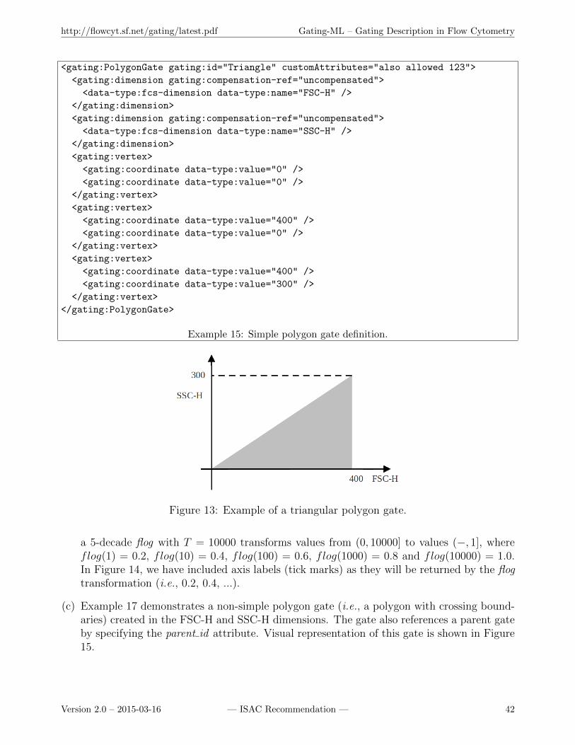
http://flowcyt.sf.net/gating/latest.pdf Gating-ML – Gating Description in Flow Cytometry
<gating:PolygonGate gating:id="Triangle" customAttributes="also allowed 123">
<gating:dimension gating:compensation-ref="uncompensated">
<data-type:fcs-dimension data-type:name="FSC-H" />
</gating:dimension>
<gating:dimension gating:compensation-ref="uncompensated">
<data-type:fcs-dimension data-type:name="SSC-H" />
</gating:dimension>
<gating:vertex>
<gating:coordinate data-type:value="0" />
<gating:coordinate data-type:value="0" />
</gating:vertex>
<gating:vertex>
<gating:coordinate data-type:value="400" />
<gating:coordinate data-type:value="0" />
</gating:vertex>
<gating:vertex>
<gating:coordinate data-type:value="400" />
<gating:coordinate data-type:value="300" />
</gating:vertex>
</gating:PolygonGate>
Example 15: Simple polygon gate definition.
Figure 13: Example of a triangular polygon gate.
a 5-decade flog with T = 10000 transforms values from (0, 10000] to values (−, 1], whereflog(1) = 0.2, flog(10) = 0.4, flog(100) = 0.6, flog(1000) = 0.8 and flog(10000) = 1.0.In Figure 14, we have included axis labels (tick marks) as they will be returned by the flogtransformation (i.e., 0.2, 0.4, ...).
(c) Example 17 demonstrates a non-simple polygon gate (i.e., a polygon with crossing bound-aries) created in the FSC-H and SSC-H dimensions. The gate also references a parent gateby specifying the parent id attribute. Visual representation of this gate is shown in Figure15.
Version 2.0 – 2015-03-16 — ISAC Recommendation — 42

http://flowcyt.sf.net/gating/latest.pdf Gating-ML – Gating Description in Flow Cytometry
<transforms:transformation transforms:id="log" customAtt="allowed here">
<transforms:flog transforms:T="10000" transforms:M="5" customA="also allowed" />
</transforms:transformation>
<gating:PolygonGate gating:id="Pentagon">
<gating:dimension gating:compensation-ref="FCS"
gating:transformation-ref="log">
<data-type:fcs-dimension data-type:name="FL1-H" />
</gating:dimension>
<gating:dimension gating:compensation-ref="uncompensated">
<data-type:fcs-dimension data-type:name="SSC-H" />
</gating:dimension>
<gating:vertex>
<gating:coordinate data-type:value="0.2" />
<gating:coordinate data-type:value="50" />
</gating:vertex>
<gating:vertex>
<gating:coordinate data-type:value="0.6" />
<gating:coordinate data-type:value="50" />
</gating:vertex>
<gating:vertex>
<gating:coordinate data-type:value="0.6" />
<gating:coordinate data-type:value="150" />
</gating:vertex>
<gating:vertex>
<gating:coordinate data-type:value="0.2" />
<gating:coordinate data-type:value="150" />
</gating:vertex>
<gating:vertex>
<gating:coordinate data-type:value="0.4" />
<gating:coordinate data-type:value="100" />
</gating:vertex>
</gating:PolygonGate>
Example 16: Polygon gate definition with transformation.
Figure 14: Example of a pentagon polygon gate.
Version 2.0 – 2015-03-16 — ISAC Recommendation — 43
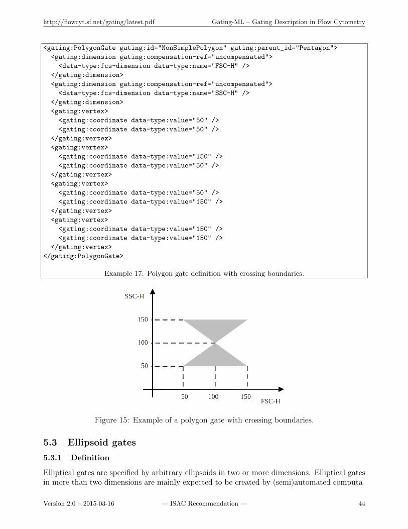
http://flowcyt.sf.net/gating/latest.pdf Gating-ML – Gating Description in Flow Cytometry
<gating:PolygonGate gating:id="NonSimplePolygon" gating:parent_id="Pentagon">
<gating:dimension gating:compensation-ref="uncompensated">
<data-type:fcs-dimension data-type:name="FSC-H" />
</gating:dimension>
<gating:dimension gating:compensation-ref="uncompensated">
<data-type:fcs-dimension data-type:name="SSC-H" />
</gating:dimension>
<gating:vertex>
<gating:coordinate data-type:value="50" />
<gating:coordinate data-type:value="50" />
</gating:vertex>
<gating:vertex>
<gating:coordinate data-type:value="150" />
<gating:coordinate data-type:value="50" />
</gating:vertex>
<gating:vertex>
<gating:coordinate data-type:value="50" />
<gating:coordinate data-type:value="150" />
</gating:vertex>
<gating:vertex>
<gating:coordinate data-type:value="150" />
<gating:coordinate data-type:value="150" />
</gating:vertex>
</gating:PolygonGate>
Example 17: Polygon gate definition with crossing boundaries.
Figure 15: Example of a polygon gate with crossing boundaries.
5.3 Ellipsoid gates
5.3.1 Definition
Elliptical gates are specified by arbitrary ellipsoids in two or more dimensions. Elliptical gatesin more than two dimensions are mainly expected to be created by (semi)automated computa-
Version 2.0 – 2015-03-16 — ISAC Recommendation — 44
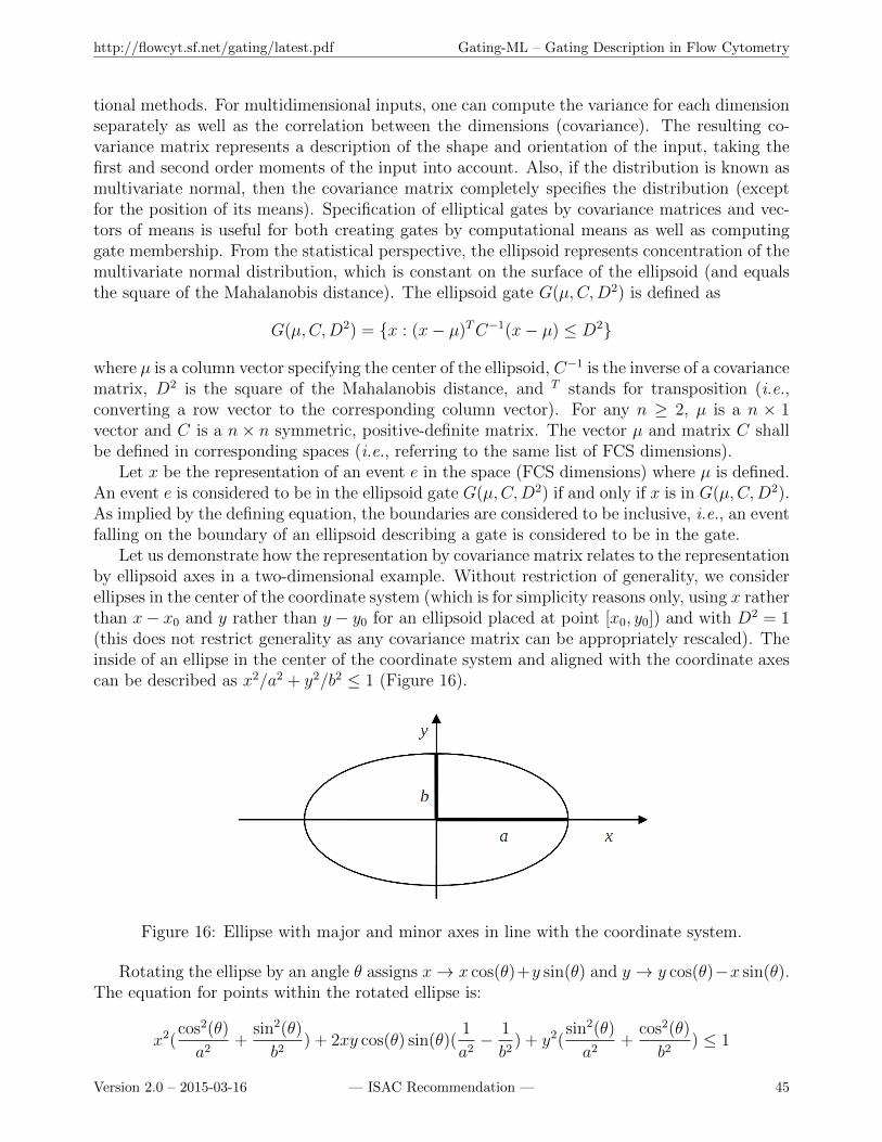
http://flowcyt.sf.net/gating/latest.pdf Gating-ML – Gating Description in Flow Cytometry
tional methods. For multidimensional inputs, one can compute the variance for each dimensionseparately as well as the correlation between the dimensions (covariance). The resulting co-variance matrix represents a description of the shape and orientation of the input, taking thefirst and second order moments of the input into account. Also, if the distribution is known asmultivariate normal, then the covariance matrix completely specifies the distribution (exceptfor the position of its means). Specification of elliptical gates by covariance matrices and vec-tors of means is useful for both creating gates by computational means as well as computinggate membership. From the statistical perspective, the ellipsoid represents concentration of themultivariate normal distribution, which is constant on the surface of the ellipsoid (and equalsthe square of the Mahalanobis distance). The ellipsoid gate G(µ,C,D2) is defined as
G(µ,C,D2) = {x : (x− µ)TC−1(x− µ) ≤ D2}
where µ is a column vector specifying the center of the ellipsoid, C−1 is the inverse of a covariancematrix, D2 is the square of the Mahalanobis distance, and T stands for transposition (i.e.,converting a row vector to the corresponding column vector). For any n ≥ 2, µ is a n × 1vector and C is a n× n symmetric, positive-definite matrix. The vector µ and matrix C shallbe defined in corresponding spaces (i.e., referring to the same list of FCS dimensions).
Let x be the representation of an event e in the space (FCS dimensions) where µ is defined.An event e is considered to be in the ellipsoid gate G(µ,C,D2) if and only if x is in G(µ,C,D2).As implied by the defining equation, the boundaries are considered to be inclusive, i.e., an eventfalling on the boundary of an ellipsoid describing a gate is considered to be in the gate.
Let us demonstrate how the representation by covariance matrix relates to the representationby ellipsoid axes in a two-dimensional example. Without restriction of generality, we considerellipses in the center of the coordinate system (which is for simplicity reasons only, using x ratherthan x− x0 and y rather than y − y0 for an ellipsoid placed at point [x0, y0]) and with D2 = 1(this does not restrict generality as any covariance matrix can be appropriately rescaled). Theinside of an ellipse in the center of the coordinate system and aligned with the coordinate axescan be described as x2/a2 + y2/b2 ≤ 1 (Figure 16).
Figure 16: Ellipse with major and minor axes in line with the coordinate system.
Rotating the ellipse by an angle θ assigns x→ x cos(θ)+y sin(θ) and y → y cos(θ)−x sin(θ).The equation for points within the rotated ellipse is:
x2(cos2(θ)
a2+
sin2(θ)
b2) + 2xy cos(θ) sin(θ)(
1
a2− 1
b2) + y2(
sin2(θ)
a2+
cos2(θ)
b2) ≤ 1
Version 2.0 – 2015-03-16 — ISAC Recommendation — 45
http://flowcyt.sf.net/gating/latest.pdf Gating-ML – Gating Description in Flow Cytometry
On the other hand, if we consider the covariance-based ellipsoid definition equation with D2 = 1and we place the ellipsoid in the center of the coordinate system (i.e., µ becomes a zero vector),then we receive:
xTC−1x ≤ 1
For a two-dimensional case and considering the symmetry of the covariance (and its inverse)matrix, this equation is specifically:
(x, y)
[C−1xx C−1xy
C−1xy C−1yy
](xy
)≤ 1
which means:
(xC−1xx + yC−1xy , xC−1xy + yC−1yy )
(xy
)≤ 1
which results in:x2C−1xx + 2xyC−1xy + y2C−1yy ≤ 1
Therefore, we see that the inverse of the covariance matrix describes an ellipse where the majorand minor axis and the rotation angle map directly onto its components, specifically:
C−1xx =cos2(θ)
a2+
sin2(θ)
b2
C−1yy =sin2(θ)
a2+
cos2(θ)
b2
C−1xy = sin(θ) cos(θ)(1
a2− 1
b2)
In the two-dimensional case, an ellipse described by µ, C, and D2 may be converted to adescription by a center, half axes, and rotation using the calculations described below. First,we calculate the eigenvalues λ1 and λ2 of the covariance matrix C as follows:
λ1,2 =(Cxx + Cyy)±
√(Cxx − Cyy)2 + 4C2
xy
2
Having λ1 and λ2, the length of the axes a and b can be calculated as
a =√λ1D2
b =√λ2D2
Next, we calculate the eigenvectors X1 and X2 of the covariance matrix C. If Cxy 6= 0, thenthe eigenvectors X1,2 are
X1,2 =
(λ1,2 − Cyy
Cxy
)If Cxy = 0, then the eigenvectors X1,2 are
X1 =
(10
)Version 2.0 – 2015-03-16 — ISAC Recommendation — 46
http://flowcyt.sf.net/gating/latest.pdf Gating-ML – Gating Description in Flow Cytometry
X2 =
(01
)The eigenvectors of the covariance matrix specify the direction in which each eigenvalue isachieved, which determines the rotation of the ellipse. For example, we can use the firsteigenvector X1 as follows: Let X1,1 be the first component of vector X1, and let X1,2 be thesecond component of vector X1. If X1,1 6= 0, then the rotation θ may be calculated as
θ = tan−1(X1,2
X1,1
)
If X1,1 = 0, then the rotation θ may be calculated as
θ = limx→+∞
tan−1(x) = π/2
Finally, the vector of means corresponds directly to the center position of the ellipsoid.
5.3.2 Syntax specification
Ellipsoid gates in n dimensions (n ≥ 2) shall be specified by a nx1 vector of means and a nxncovariance matrix (symmetric, positive-definite). To specify an ellipsoid gate the EllipsoidGateelement shall be used as follows:
(a) The id attribute shall be used to identify the gate for further referencing purposes, e.g., asdescribed in sections 4.4 and 5.5.
(b) The parent id attribute may be used to reference a parent gate as described in section 4.4.
(c) A custom info element may be placed at the beginning of the EllipsoidGate element. Thecustom info element may contain any additional custom information related to this gate;the format of this element (i.e., its attributes, sub elements, etc.) is not constrained bythis specification as long as the document remains a valid XML.
(d) Two or more dimensions shall be described by two or more dimension elements placed atthe beginning of the EllipsoidGate element or right after the custom info element if thecustom info element is used. For further syntax description purposes, let n be the numberof dimensions specified.
(e) Each dimension element shall specify compensation by including the compensation-ref at-tribute as specified in section 4.2. The value of this attribute may be one of the following:FCS, uncompensated, or the identifier of a spectrum matrix defined within the Gating-MLfile.
(f) Each dimension element may use the transformation-ref attribute to reference a scaletransformation. If used, the value of this attribute shall contain the identifier of a scaletransformation defined within this Gating-ML file (see section 4.2.3).
(g) Each dimension element shall reference a dimension as described in section 4.1, i.e., byincluding an fcs-dimension element or a new-dimension element. The same FCS dimensionor new dimension may not be used more than once within the gate definition.
Version 2.0 – 2015-03-16 — ISAC Recommendation — 47
http://flowcyt.sf.net/gating/latest.pdf Gating-ML – Gating Description in Flow Cytometry
(h) The mean element shall follow after the dimension elements to describe the mean vector(center of the ellipsoid). It shall include n coordinate elements, each one specifying acoordinate of the mean point in space by a value attribute. The first coordinate correspondsto the first dimension, the second coordinate to the second dimension, etc. The numberof coordinate elements specified for the mean element shall correspond to the number ofdimension elements specified at the beginning of the ellipsoid gate definition.
(i) The covarianceMatrix element shall follow after the mean element.
(j) The covarianceMatrix element shall include n row sub elements, each of them including nentry sub elements (where n is the number of dimension elements specified at the beginningof the ellipsoid gate definition).
(k) Each entry element shall specify its value by the value attribute.
(l) A distanceSquare element shall follow after the covarianceMatrix element and it shall spec-ify the square of the Mahalanobis distance (i.e., D2) using the value attribute.
5.3.3 Validity conditions
An ellipsoid gate definition is valid if and only if:
(a) It is valid according to the XML schema.
(b) If used, the parent id attribute does not introduce any circular dependency (see also sections3.3.6, 3.3.7, and 3.4.1).
(c) There are n dimension elements describing n dimensions where n ≥ 2.
(d) The gating dimensions are different from one another, i.e., the values of the name attributesare unique among all fcs-dimension elements (if used) in the gate definition, and the valuesof the transformation-ref attributes are unique among all new-dimension elements (if used)in the gate definition.
(e) The value of the compensation-ref attribute of each dimension element equals to eitherFCS, uncompensated, or an identifier of a spectrum matrix defined within the Gating-MLfile.
(f) If used, the value of the transformation-ref attribute of the dimension element shall containan identifier of a scale transformation defined within the same Gating-ML file.
(g) If used, the value of the transformation-ref attribute of the new-dimension element shallcontain an identifier of a transformation that creates a new dimension, i.e., an identifier ofa parametrized ratio transformation.
(h) The covarianceMatrix element includes n row sub elements.
(i) Each row element includes n entry elements.
(j) The covarianceMatrix element defines a valid covariance matrix, i.e., a symmetric, positive-definite matrix.
Version 2.0 – 2015-03-16 — ISAC Recommendation — 48
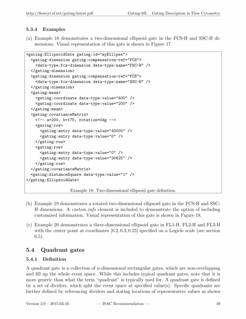
http://flowcyt.sf.net/gating/latest.pdf Gating-ML – Gating Description in Flow Cytometry
5.3.4 Examples
(a) Example 18 demonstrates a two-dimensional ellipsoid gate in the FCS-H and SSC-H di-mensions. Visual representation of this gate is shown in Figure 17.
<gating:EllipsoidGate gating:id="myEllipse">
<gating:dimension gating:compensation-ref="FCS">
<data-type:fcs-dimension data-type:name="FSC-H" />
</gating:dimension>
<gating:dimension gating:compensation-ref="FCS">
<data-type:fcs-dimension data-type:name="SSC-H" />
</gating:dimension>
<gating:mean>
<gating:coordinate data-type:value="400" />
<gating:coordinate data-type:value="200" />
</gating:mean>
<gating:covarianceMatrix>
<!-- a=200, b=175, rotation=0dg -->
<gating:row>
<gating:entry data-type:value="40000" />
<gating:entry data-type:value="0" />
</gating:row>
<gating:row>
<gating:entry data-type:value="0" />
<gating:entry data-type:value="30625" />
</gating:row>
</gating:covarianceMatrix>
<gating:distanceSquare data-type:value="1" />
</gating:EllipsoidGate>
Example 18: Two-dimensional ellipsoid gate definition.
(b) Example 19 demonstrates a rotated two-dimensional ellipsoid gate in the FCS-H and SSC-H dimensions. A custom info element is included to demonstrate the option of includingcustomized information. Visual representation of this gate is shown in Figure 18.
(c) Example 20 demonstrates a three-dimensional ellipsoid gate in FL1-H, FL2-H and FL3-Hwith the center point at coordinates [0.2, 0.3, 0.25] specified on a Logicle scale (see section6.5).
5.4 Quadrant gates
5.4.1 Definition
A quadrant gate is a collection of n-dimensional rectangular gates, which are non-overlappingand fill up the whole event space. While this includes typical quadrant gates, note that it ismore generic than what the term “quadrant” is typically used for. A quadrant gate is definedby a set of dividers, which split the event space at specified value(s). Specific quadrants arefurther defined by referencing dividers and stating locations of representative values as shown
Version 2.0 – 2015-03-16 — ISAC Recommendation — 49

http://flowcyt.sf.net/gating/latest.pdf Gating-ML – Gating Description in Flow Cytometry
Figure 17: Example of a two dimensional ellipsoid gate.
<gating:EllipsoidGate gating:id="myEllipse2">
<data-type:custom_info a="37" b="30" rotation="-45dg" />
<gating:dimension gating:compensation-ref="uncompensated">
<data-type:fcs-dimension data-type:name="FSC-H" />
</gating:dimension>
<gating:dimension gating:compensation-ref="uncompensated">
<data-type:fcs-dimension data-type:name="SSC-H" />
</gating:dimension>
<gating:mean>
<gating:coordinate data-type:value="40" />
<gating:coordinate data-type:value="40" />
</gating:mean>
<gating:covarianceMatrix>
<gating:row>
<gating:entry data-type:value="1134.5" />
<gating:entry data-type:value="-234.5" />
</gating:row>
<gating:row>
<gating:entry data-type:value="-234.5" />
<gating:entry data-type:value="1134.5" />
</gating:row>
</gating:covarianceMatrix>
<gating:distanceSquare data-type:value="1" />
</gating:EllipsoidGate>
Example 19: Rotated two-dimensional ellipsoid gate definition.
Version 2.0 – 2015-03-16 — ISAC Recommendation — 50
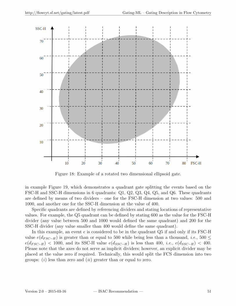
http://flowcyt.sf.net/gating/latest.pdf Gating-ML – Gating Description in Flow Cytometry
Figure 18: Example of a rotated two dimensional ellipsoid gate.
in example Figure 19, which demonstrates a quadrant gate splitting the events based on theFSC-H and SSC-H dimensions in 6 quadrants: Q1, Q2, Q3, Q4, Q5, and Q6. These quadrantsare defined by means of two dividers – one for the FSC-H dimension at two values: 500 and1000, and another one for the SSC-H dimension at the value of 400.
Specific quadrants are defined by referencing dividers and stating locations of representativevalues. For example, the Q5 quadrant can be defined by stating 600 as the value for the FSC-Hdivider (any value between 500 and 1000 would defined the same quadrant) and 200 for theSSC-H divider (any value smaller than 400 would define the same quadrant).
In this example, an event e is considered to be in the quadrant Q5 if and only if its FSC-Hvalue e(dFSC−H) is greater than or equal to 500 while being less than a thousand, i.e., 500 ≤e(dFSC−H) < 1000, and its SSC-H value e(dSSC−H) is less than 400, i.e., e(dSSC−H) < 400.Please note that the axes do not serve as implicit dividers; however, an explicit divider may beplaced at the value zero if required. Technically, this would split the FCS dimension into twogroups: (i) less than zero and (ii) greater than or equal to zero.
Version 2.0 – 2015-03-16 — ISAC Recommendation — 51
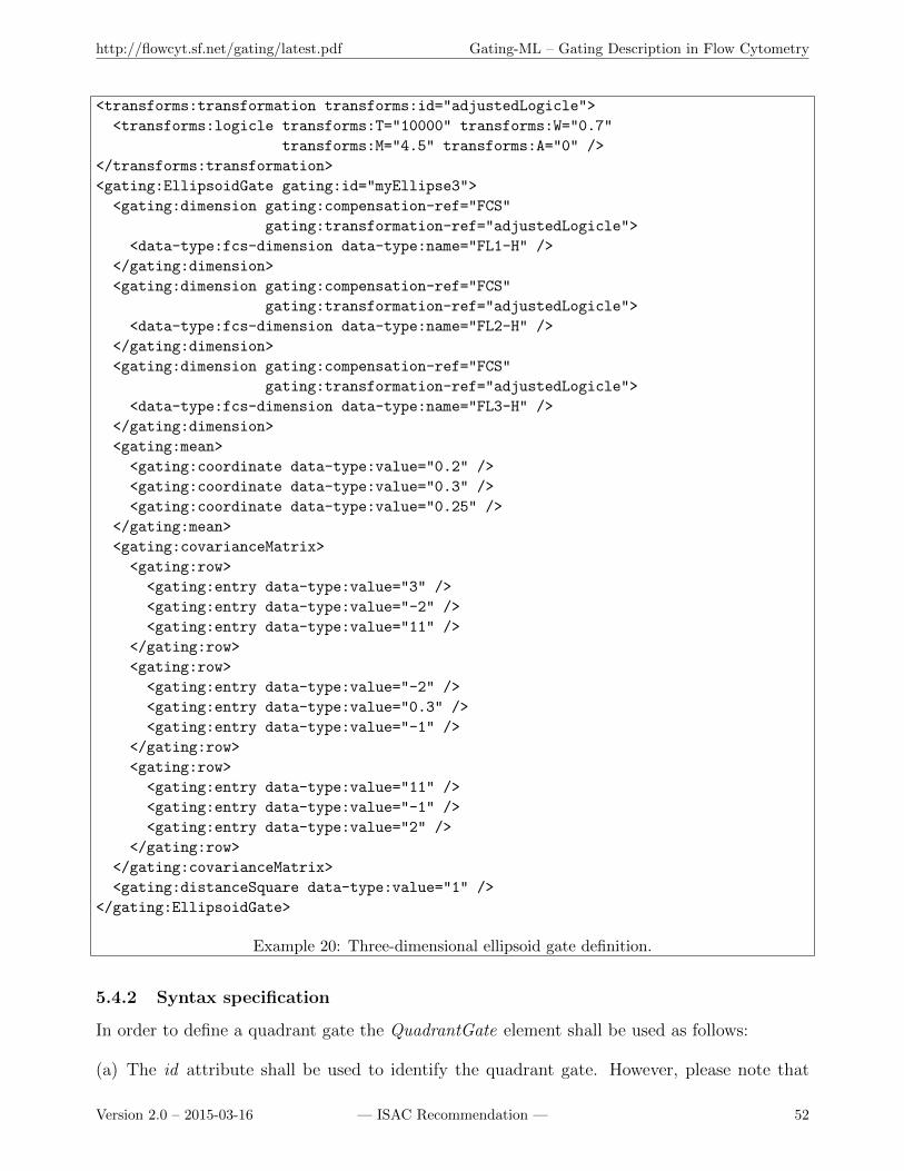
http://flowcyt.sf.net/gating/latest.pdf Gating-ML – Gating Description in Flow Cytometry
<transforms:transformation transforms:id="adjustedLogicle">
<transforms:logicle transforms:T="10000" transforms:W="0.7"
transforms:M="4.5" transforms:A="0" />
</transforms:transformation>
<gating:EllipsoidGate gating:id="myEllipse3">
<gating:dimension gating:compensation-ref="FCS"
gating:transformation-ref="adjustedLogicle">
<data-type:fcs-dimension data-type:name="FL1-H" />
</gating:dimension>
<gating:dimension gating:compensation-ref="FCS"
gating:transformation-ref="adjustedLogicle">
<data-type:fcs-dimension data-type:name="FL2-H" />
</gating:dimension>
<gating:dimension gating:compensation-ref="FCS"
gating:transformation-ref="adjustedLogicle">
<data-type:fcs-dimension data-type:name="FL3-H" />
</gating:dimension>
<gating:mean>
<gating:coordinate data-type:value="0.2" />
<gating:coordinate data-type:value="0.3" />
<gating:coordinate data-type:value="0.25" />
</gating:mean>
<gating:covarianceMatrix>
<gating:row>
<gating:entry data-type:value="3" />
<gating:entry data-type:value="-2" />
<gating:entry data-type:value="11" />
</gating:row>
<gating:row>
<gating:entry data-type:value="-2" />
<gating:entry data-type:value="0.3" />
<gating:entry data-type:value="-1" />
</gating:row>
<gating:row>
<gating:entry data-type:value="11" />
<gating:entry data-type:value="-1" />
<gating:entry data-type:value="2" />
</gating:row>
</gating:covarianceMatrix>
<gating:distanceSquare data-type:value="1" />
</gating:EllipsoidGate>
Example 20: Three-dimensional ellipsoid gate definition.
5.4.2 Syntax specification
In order to define a quadrant gate the QuadrantGate element shall be used as follows:
(a) The id attribute shall be used to identify the quadrant gate. However, please note that
Version 2.0 – 2015-03-16 — ISAC Recommendation — 52
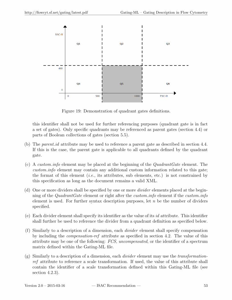
http://flowcyt.sf.net/gating/latest.pdf Gating-ML – Gating Description in Flow Cytometry
Figure 19: Demonstration of quadrant gates definitions.
this identifier shall not be used for further referencing purposes (quadrant gate is in facta set of gates). Only specific quadrants may be referenced as parent gates (section 4.4) orparts of Boolean collections of gates (section 5.5).
(b) The parent id attribute may be used to reference a parent gate as described in section 4.4.If this is the case, the parent gate is applicable to all quadrants defined by the quadrantgate.
(c) A custom info element may be placed at the beginning of the QuadrantGate element. Thecustom info element may contain any additional custom information related to this gate;the format of this element (i.e., its attributes, sub elements, etc.) is not constrained bythis specification as long as the document remains a valid XML.
(d) One or more dividers shall be specified by one or more divider elements placed at the begin-ning of the QuadrantGate element or right after the custom info element if the custom infoelement is used. For further syntax description purposes, let n be the number of dividersspecified.
(e) Each divider element shall specify its identifier as the value of its id attribute. This identifiershall further be used to reference the divider from a quadrant definition as specified below.
(f) Similarly to a description of a dimension, each divider element shall specify compensationby including the compensation-ref attribute as specified in section 4.2. The value of thisattribute may be one of the following: FCS, uncompensated, or the identifier of a spectrummatrix defined within the Gating-ML file.
(g) Similarly to a description of a dimension, each divider element may use the transformation-ref attribute to reference a scale transformation. If used, the value of this attribute shallcontain the identifier of a scale transformation defined within this Gating-ML file (seesection 4.2.3).
Version 2.0 – 2015-03-16 — ISAC Recommendation — 53
http://flowcyt.sf.net/gating/latest.pdf Gating-ML – Gating Description in Flow Cytometry
(h) Each divider element shall reference a dimension as described in section 4.1, i.e., by in-cluding an fcs-dimension element or a new-dimension element. The same FCS dimensionor new dimension may not be used more than once within the gate definition.
(i) Each divider element shall specify at least one divider value by including one or more valuesub elements. Including multiple value elements results in “splitting” a particular FCSdimension at multiple values such as shown for the FCS-H dimension in Figure 19.
(j) The value element shall contain a numerical value, i.e., the contents of the value elementshall be a numerical value. In addition, values shall be different from each other andarranged in an increasing order if multiple values (i.e., value elements) are used for a singledivider.
(k) The divider definition(s) shall be followed by one or more quadrants defined by one or moreQuadrant elements. Please note that not every quadrant needs to be defined (e.g., example23).
(l) Each Quadrant element shall use the id attribute to identify the quadrant for furtherreferencing purposes, i.e., to be referenceable as a parent gate (section 4.4) or in a Booleancollections of gates (section 5.5).
(m) Each Quadrant element shall specify m position sub elements where m is greater or equal to1 while being less or equal to n where n is the number of dividers specified at the beginningof the quadrant gate definition. Specifying less positions than the number of dividers meansthat the omitted dividers are not part of the definition of a particular quadrant, i.e., thequadrant reaches to both sides of the omitted dividers in that dimension (e.g., example 23).
(n) Each position element shall include a divider ref attribute referencing a divider by itsidentifier. No two position elements within the same Quadrant element shall reference thesame divider.
(o) Each position element shall include a location attribute giving a representative value forevents in this quadrant considering the divider values specified earlier. The value of thelocation attribute shall be different from the value(s) specified within the referenced dividerelement.
5.4.3 Validity conditions
A quadrant gate definition is valid if and only if:
(a) It is valid according to the XML schema.
(b) If used, the parent id attribute does not introduce any circular dependency (see also sections3.3.6, 3.3.7 and 3.4.1).
(c) The dimensions are different from one another, i.e., the values of the name attributesare unique among all fcs-dimension elements (if used) across all divider elements in thegate definition, and the values of the transformation-ref attributes are unique among allnew-dimension elements (if used) across all divider elements in the gate definition.
Version 2.0 – 2015-03-16 — ISAC Recommendation — 54
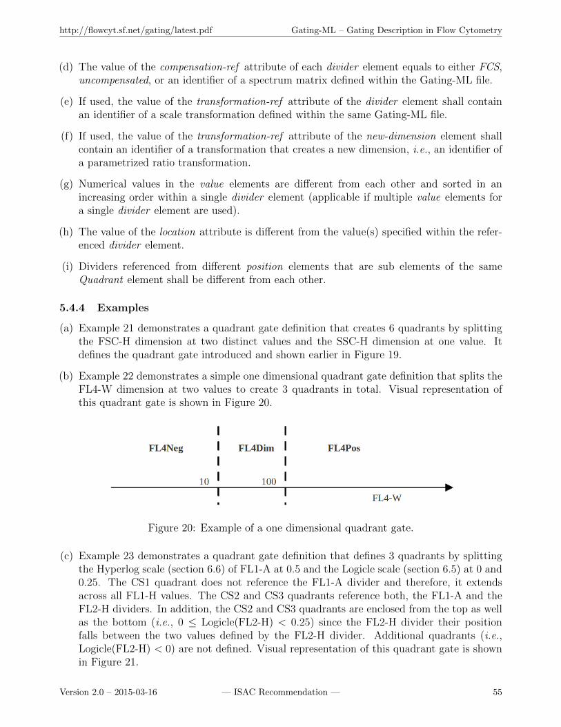
http://flowcyt.sf.net/gating/latest.pdf Gating-ML – Gating Description in Flow Cytometry
(d) The value of the compensation-ref attribute of each divider element equals to either FCS,uncompensated, or an identifier of a spectrum matrix defined within the Gating-ML file.
(e) If used, the value of the transformation-ref attribute of the divider element shall containan identifier of a scale transformation defined within the same Gating-ML file.
(f) If used, the value of the transformation-ref attribute of the new-dimension element shallcontain an identifier of a transformation that creates a new dimension, i.e., an identifier ofa parametrized ratio transformation.
(g) Numerical values in the value elements are different from each other and sorted in anincreasing order within a single divider element (applicable if multiple value elements fora single divider element are used).
(h) The value of the location attribute is different from the value(s) specified within the refer-enced divider element.
(i) Dividers referenced from different position elements that are sub elements of the sameQuadrant element shall be different from each other.
5.4.4 Examples
(a) Example 21 demonstrates a quadrant gate definition that creates 6 quadrants by splittingthe FSC-H dimension at two distinct values and the SSC-H dimension at one value. Itdefines the quadrant gate introduced and shown earlier in Figure 19.
(b) Example 22 demonstrates a simple one dimensional quadrant gate definition that splits theFL4-W dimension at two values to create 3 quadrants in total. Visual representation ofthis quadrant gate is shown in Figure 20.
Figure 20: Example of a one dimensional quadrant gate.
(c) Example 23 demonstrates a quadrant gate definition that defines 3 quadrants by splittingthe Hyperlog scale (section 6.6) of FL1-A at 0.5 and the Logicle scale (section 6.5) at 0 and0.25. The CS1 quadrant does not reference the FL1-A divider and therefore, it extendsacross all FL1-H values. The CS2 and CS3 quadrants reference both, the FL1-A and theFL2-H dividers. In addition, the CS2 and CS3 quadrants are enclosed from the top as wellas the bottom (i.e., 0 ≤ Logicle(FL2-H) < 0.25) since the FL2-H divider their positionfalls between the two values defined by the FL2-H divider. Additional quadrants (i.e.,Logicle(FL2-H) < 0) are not defined. Visual representation of this quadrant gate is shownin Figure 21.
Version 2.0 – 2015-03-16 — ISAC Recommendation — 55
http://flowcyt.sf.net/gating/latest.pdf Gating-ML – Gating Description in Flow Cytometry
<gating:QuadrantGate gating:id="myQuadrantGate">
<data-type:custom_info>FSC-H is split at 500 and 1000</data-type:custom_info>
<gating:divider gating:id="FSC" gating:compensation-ref="uncompensated">
<data-type:fcs-dimension data-type:name="FSC-H" />
<gating:value>500</gating:value>
<gating:value>1000</gating:value>
</gating:divider>
<gating:divider gating:id="SSC" gating:compensation-ref="uncompensated">
<data-type:fcs-dimension data-type:name="SSC-H" />
<gating:value>400</gating:value>
</gating:divider>
<gating:Quadrant gating:id="Q1">
<gating:position gating:divider_ref="FSC" gating:location="200" />
<gating:position gating:divider_ref="SSC" gating:location="600" />
</gating:Quadrant>
<gating:Quadrant gating:id="Q2">
<gating:position gating:divider_ref="FSC" gating:location="600" />
<gating:position gating:divider_ref="SSC" gating:location="600" />
</gating:Quadrant>
<gating:Quadrant gating:id="Q3">
<gating:position gating:divider_ref="FSC" gating:location="1700" />
<gating:position gating:divider_ref="SSC" gating:location="600" />
</gating:Quadrant>
<gating:Quadrant gating:id="Q4">
<gating:position gating:divider_ref="FSC" gating:location="200" />
<gating:position gating:divider_ref="SSC" gating:location="200" />
</gating:Quadrant>
<gating:Quadrant gating:id="Q5">
<gating:position gating:divider_ref="FSC" gating:location="600" />
<gating:position gating:divider_ref="SSC" gating:location="200" />
</gating:Quadrant>
<gating:Quadrant gating:id="Q6">
<gating:position gating:divider_ref="FSC" gating:location="1700" />
<gating:position gating:divider_ref="SSC" gating:location="200" />
</gating:Quadrant>
</gating:QuadrantGate>
Example 21: Quadrant gate definition splitting the FSC-H dimension at multiple values.
5.5 Boolean gates
5.5.1 Definition
A Boolean gate is a gate created based on other gates using Boolean operators – AND, OR, orNOT. NOT is a unary operator. The AND and OR operators are extended to allow for two ormore operands. The operators have the following semantic:
(a) Let gate G be created as G = NOT (G0). An event e is in the gate G if and only if e is notin the gate G0. Formally, e ∈ G⇔ e 6∈ G0.
Version 2.0 – 2015-03-16 — ISAC Recommendation — 56
http://flowcyt.sf.net/gating/latest.pdf Gating-ML – Gating Description in Flow Cytometry
<gating:QuadrantGate gating:id="myQuadrantGate2">
<gating:divider gating:id="FL4" gating:compensation-ref="FCS">
<data-type:fcs-dimension data-type:name="FL4-W" />
<gating:value>10</gating:value>
<gating:value>100</gating:value>
</gating:divider>
<gating:Quadrant gating:id="FL4Neg">
<gating:position gating:divider_ref="FL4" gating:location="0" />
</gating:Quadrant>
<gating:Quadrant gating:id="FL4Dim">
<gating:position gating:divider_ref="FL4" gating:location="50" />
</gating:Quadrant>
<gating:Quadrant gating:id="FL4Pos">
<gating:position gating:divider_ref="FL4" gating:location="500" />
</gating:Quadrant>
</gating:QuadrantGate>
Example 22: One dimensional quadrant gate definition.
<gating:QuadrantGate gating:id="myQuadrantGate3">
<data-type:custom_info note="Assuming transformations defined elsewhere." />
<gating:divider gating:id="FL1" gating:compensation-ref="FCS"
gating:transformation-ref="myHyperlog1">
<data-type:fcs-dimension data-type:name="FL1-A"/>
<gating:value>0.5</gating:value>
</gating:divider>
<gating:divider gating:id="FL2" gating:compensation-ref="FCS"
gating:transformation-ref="myLogicle1">
<data-type:fcs-dimension data-type:name="FL2-A"/>
<gating:value>0</gating:value>
<gating:value>0.25</gating:value>
</gating:divider>
<gating:Quadrant gating:id="CS1">
<gating:position gating:divider_ref="FL2" gating:location="1" />
</gating:Quadrant>
<gating:Quadrant gating:id="CS2">
<gating:position gating:divider_ref="FL1" gating:location="0.1" />
<gating:position gating:divider_ref="FL2" gating:location="0.1" />
</gating:Quadrant>
<gating:Quadrant gating:id="CS3">
<gating:position gating:divider_ref="FL1" gating:location="0.6" />
<gating:position gating:divider_ref="FL2" gating:location="0.1" />
</gating:Quadrant>
</gating:QuadrantGate>
Example 23: Quadrant gate definition demonstrating “merging” of quadrants.
(b) Let gate G be created as G = AND(G1, G2, . . . , Gn), n ∈ N, n ≥ 2. An event e is in the
Version 2.0 – 2015-03-16 — ISAC Recommendation — 57
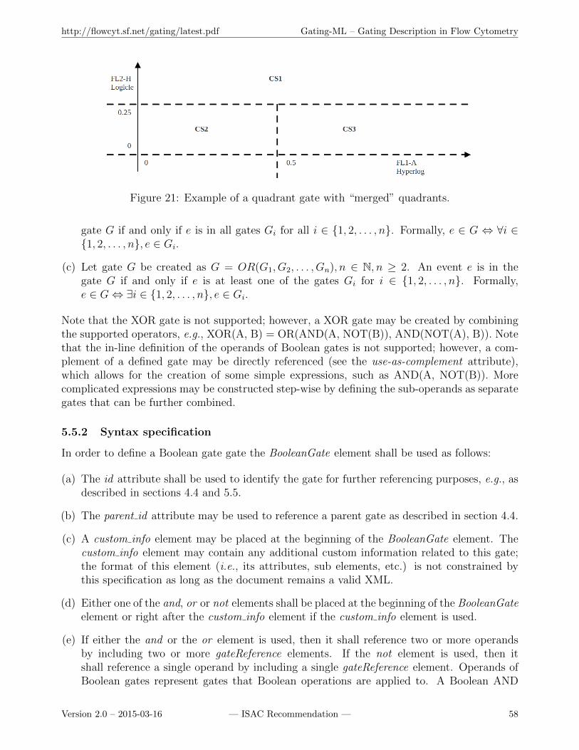
http://flowcyt.sf.net/gating/latest.pdf Gating-ML – Gating Description in Flow Cytometry
Figure 21: Example of a quadrant gate with “merged” quadrants.
gate G if and only if e is in all gates Gi for all i ∈ {1, 2, . . . , n}. Formally, e ∈ G ⇔ ∀i ∈{1, 2, . . . , n}, e ∈ Gi.
(c) Let gate G be created as G = OR(G1, G2, . . . , Gn), n ∈ N, n ≥ 2. An event e is in thegate G if and only if e is at least one of the gates Gi for i ∈ {1, 2, . . . , n}. Formally,e ∈ G⇔ ∃i ∈ {1, 2, . . . , n}, e ∈ Gi.
Note that the XOR gate is not supported; however, a XOR gate may be created by combiningthe supported operators, e.g., XOR(A, B) = OR(AND(A, NOT(B)), AND(NOT(A), B)). Notethat the in-line definition of the operands of Boolean gates is not supported; however, a com-plement of a defined gate may be directly referenced (see the use-as-complement attribute),which allows for the creation of some simple expressions, such as AND(A, NOT(B)). Morecomplicated expressions may be constructed step-wise by defining the sub-operands as separategates that can be further combined.
5.5.2 Syntax specification
In order to define a Boolean gate gate the BooleanGate element shall be used as follows:
(a) The id attribute shall be used to identify the gate for further referencing purposes, e.g., asdescribed in sections 4.4 and 5.5.
(b) The parent id attribute may be used to reference a parent gate as described in section 4.4.
(c) A custom info element may be placed at the beginning of the BooleanGate element. Thecustom info element may contain any additional custom information related to this gate;the format of this element (i.e., its attributes, sub elements, etc.) is not constrained bythis specification as long as the document remains a valid XML.
(d) Either one of the and, or or not elements shall be placed at the beginning of the BooleanGateelement or right after the custom info element if the custom info element is used.
(e) If either the and or the or element is used, then it shall reference two or more operandsby including two or more gateReference elements. If the not element is used, then itshall reference a single operand by including a single gateReference element. Operands ofBoolean gates represent gates that Boolean operations are applied to. A Boolean AND
Version 2.0 – 2015-03-16 — ISAC Recommendation — 58
http://flowcyt.sf.net/gating/latest.pdf Gating-ML – Gating Description in Flow Cytometry
operation shall be computed for the and operator so that an event is in the “and gate”if and only if it is in all the referenced operand gates. A Boolean OR operation shall becomputed for the or operator so that an event is in the “or gate” if and only if it is in atleast one of the referenced operand gates. A Boolean NOT operation shall be computedfor the not operator so that an event is in the “not gate” if and only if it is not in thereferenced operand gate.
(f) The gateReference element shall use the ref attribute to reference another rectangle, poly-gon, ellipsoid or Boolean gate, or a specific quadrant from a quadrant gate definition byits identifier, i.e., by the id attribute of a RectangleGate element, PolygonGate element,EllipsoidGate element, BooleanGate element or Quadrant element defined elsewhere (i.e.,outside of this Boolean gate definition) in the Gating-ML file.
(g) The gateReference element may use the optional boolean use-as-complement attribute,which may be set to either false (default) or true. Omitting this attribute has the sameeffect as setting it to false. Setting this attribute to true indicates that the complement ofthe particular operand (i.e., NOT(...) ) shall be used instead of the operand itself.
5.5.3 Validity conditions
A Boolean gate definition is valid if and only if:
(a) It is valid according to the XML schema.
(b) If used, the parent id attribute does not introduce any circular dependency (see also sections3.3.6, 3.3.7 and 3.4.1).
(c) The values of the ref attribute of all included gateReference elements reference a validrectangle, polygon, ellipsoid or Boolean gate, or a specific quadrant from a quadrant gatedefinition.
(d) The Boolean gate does not introduce any circular dependency, i.e., none of the operandsare dependent (directly or indirectly) on this Boolean gate (see also sections 3.3.6, 3.3.7and 3.4.1).
5.5.4 Examples
(a) Example 24 demonstrates an “OR” Boolean gate combining a rectangle gate with an ellip-soid gate. Visual representation of this Boolean gate is shown in Figure 22.
(b) Example 25 demonstrates a “NOT” Boolean gate applied on the Boolean gate defined inexample 25. This “NOT” gate contains all the events that are outside of the Boolean gateshown in Figure 22.
(c) Example 26 demonstrates an “AND” Boolean gate that creates the intersection of theellipsoid gate “myEllipse” defined in example 18, the polygon gate “Pentagon” definedin example 16 and the complement of the “FL4Dim” quadrant from the quadrant gatedefined in example 22. This can also be expressed as AND(“myEllipse”, “Pentagon”,NOT(“FL4Dim”)). This “AND” gate is supposed to be applied on the population defined
Version 2.0 – 2015-03-16 — ISAC Recommendation — 59
http://flowcyt.sf.net/gating/latest.pdf Gating-ML – Gating Description in Flow Cytometry
<gating:BooleanGate gating:id="myBoolean">
<gating:or>
<gating:gateReference gating:ref="R1" />
<gating:gateReference gating:ref="E1" />
</gating:or>
</gating:BooleanGate>
<gating:RectangleGate gating:id="R1">
<gating:dimension gating:compensation-ref="uncompensated"
gating:min="10" gating:max="30">
<data-type:fcs-dimension data-type:name="FSC-H" />
</gating:dimension>
<gating:dimension gating:compensation-ref="uncompensated"
gating:min="10" gating:max="20">
<data-type:fcs-dimension data-type:name="SSC-H" />
</gating:dimension>
</gating:RectangleGate>
<gating:EllipsoidGate gating:id="E1">
<gating:dimension gating:compensation-ref="uncompensated">
<data-type:fcs-dimension data-type:name="FSC-H" />
</gating:dimension>
<gating:dimension gating:compensation-ref="uncompensated">
<data-type:fcs-dimension data-type:name="SSC-H" />
</gating:dimension>
<gating:mean>
<gating:coordinate data-type:value="30" />
<gating:coordinate data-type:value="15" />
</gating:mean>
<gating:covarianceMatrix>
<gating:row>
<gating:entry data-type:value="100" />
<gating:entry data-type:value="0" />
</gating:row>
<gating:row>
<gating:entry data-type:value="0" />
<gating:entry data-type:value="25" />
</gating:row>
</gating:covarianceMatrix>
<gating:distanceSquare data-type:value="1" />
</gating:EllipsoidGate>
Example 24: Boolean OR gate definition combining a rectangle gate with an ellipse gate.
<gating:BooleanGate gating:id="myBoolean2">
<gating:not><gating:gateReference gating:ref="myBoolean" /></gating:not>
</gating:BooleanGate>
Example 25: Boolean NOT gate definition.
Version 2.0 – 2015-03-16 — ISAC Recommendation — 60

http://flowcyt.sf.net/gating/latest.pdf Gating-ML – Gating Description in Flow Cytometry
Figure 22: Example of a Boolean OR gate.
by the “Range FCS o100” parent gate defined in example 12. In terms of the gating(event filtering) operation, including the “Range FCS o100” gate as another operand ofthe “AND” gate rather than listing it as a parent gate would produce exactly the sameresults.
<gating:BooleanGate gating:id="myBoolean3" gating:parent_id="Range_FCS_o100">
<gating:and>
<gating:gateReference gating:ref="myEllipse" />
<gating:gateReference gating:ref="Pentagon" />
<gating:gateReference gating:ref="FL4Dim" gating:use-as-complement="true" />
</gating:and>
</gating:BooleanGate>
Example 26: Boolean AND gate definition with one operand used as complement.
6 Scale transformation description
6.1 Bounding transformations
6.1.1 Definition
A boundary may be defined for any scaling transformation as described further in this section,or for any additional transformation as described in section 8. A boundary is defined by thebound function as follows:
bound(x, boundmin, boundmax) =
boundmin if x < boundmin
boundmax if x > boundmax
x otherwise
Version 2.0 – 2015-03-16 — ISAC Recommendation — 61
http://flowcyt.sf.net/gating/latest.pdf Gating-ML – Gating Description in Flow Cytometry
• x ∈ R is the value that the boundary is applied to, such as the result of a scalingtransformation, or the result of an additional transformation as described in section 8.
• boundmin ∈ R is the boundary lower bound.
• boundmax ∈ R, boundmax >= boundmin is the boundary upper bound.
6.1.2 Use case description
A boundary restricts a value x (i.e. the result of a transformation that the boundary is definedfor) to the [boundmin, boundmax] interval. Using a boundary allows for simple unambiguousencoding of gating performed by software tools that pile “off-scale” events on the “graph axes”.In these cases, if the selected visualization (scaling transformation) is not quite appropriate,certain events could “fall of the graph”. However, instead of “losing” these events, some soft-ware tools prefer to shift them to a predefined minimum or maximum, which may affect gatemembership of these events. A Gating-ML boundary may be used in order to mimic suchbehavior in Gating-ML and encode these gates in a reproducible manner.
6.1.3 Syntax specification
A boundary shall be specified by including the boundMin attribute, the boundMax attribute,or both, in any transformation element. If the boundMin attribute is not included, then −∞(negative infinity) shall be considered as the boundMin value. If the boundMax attribute is notincluded, then ∞ (infinity) shall be considered as the boundMax value.
6.1.4 Validity conditions
A transformation with a boundary is valid if and only if
(a) It is valid according to the XML schema.
(b) If both the boundMin and the boundMax attributes are included, then the value of theboundMin attribute is less than or equal to the value of the boundMax attribute.
6.1.5 Examples
(a) Example 27 demonstrates the definition of a Logicle transformation (see section 6.5) withboundMin = 0.1 and boundMax = 0.9.
<transforms:transformation transforms:id="Bound_Logicle"
transforms:boundMin="0.1" transforms:boundMax="0.9">
<transforms:logicle transforms:T="262144" transforms:M="4.5"
transforms:W="0.5" transforms:A="0" />
</transforms:transformation>
Example 27: Logicle transformation with a boundary restricting its result to the [0.1,0.9] interval.
In order to illustrate the effect of this boundary, let us assume we have a polygon gate thatreferences the Logicle transformation defined in example 27. This polygon gate is definedin example 28.
Version 2.0 – 2015-03-16 — ISAC Recommendation — 62
http://flowcyt.sf.net/gating/latest.pdf Gating-ML – Gating Description in Flow Cytometry
<gating:PolygonGate gating:id="BlueTriangle">
<gating:dimension gating:compensation-ref="FCS"
gating:transformation-ref="Bound_Logicle" >
<data-type:fcs-dimension data-type:name="FITC-A"/>
</gating:dimension>
<gating:dimension gating:compensation-ref="FCS"
gating:transformation-ref="Bound_Logicle">
<data-type:fcs-dimension data-type:name="PE-A"/>
</gating:dimension>
<gating:vertex>
<gating:coordinate data-type:value="0.4"/>
<gating:coordinate data-type:value="0"/>
</gating:vertex>
<gating:vertex>
<gating:coordinate data-type:value="0"/>
<gating:coordinate data-type:value="0.4"/>
</gating:vertex>
<gating:vertex>
<gating:coordinate data-type:value="1"/>
<gating:coordinate data-type:value="1"/>
</gating:vertex>
</gating:PolygonGate>
Example 28: Polygon gate referencing a transformation with a boundary.
This gate is shown in Figure 23. On the left in panel A, the blue triangle demonstrates thepolygon gate as defined in example 28, and the red square demonstrates the boundary that ispart of the scaling transformation defined in example 27. The effect of the transformationboundary is shown on a few example events that are positioned using a correspondingLogicle scale, but without considering the boundary. Red crosses indicate events outsideof the polygon gate, and green crosses events in the gate. Noticeably, there are severalgreen crosses placed outside of the blue triangle. These events are outside of the definedboundary. Once the boundary is applied, these events are pulled towards the red square,which brings them in the blue triangle and explains why they are considered to be in thepolygon gate. Panel B on the right demonstrates an alternative view of the boundaryeffect, which can be imagined as extending the gate to ±∞ in places where it crosses thetransformation boundary.
(b) Example 29 demonstrates the definition of an inverse hyperbolic sine transformation (seesection 6.4) with a left boundary restricting its result to the [−0.1,∞] interval.
<transforms:transformation transforms:id="Left_Bound_Arcsinh_262144_4.5_0"
transforms:boundMin="-0.1">
<transforms:fasinh transforms:T="262144" transforms:M="4.5" transforms:A="0" />
</transforms:transformation>
Example 29: Inverse hyperbolic sine transformation with a left boundary.
Version 2.0 – 2015-03-16 — ISAC Recommendation — 63
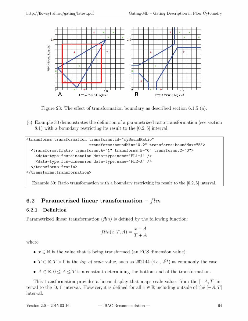
http://flowcyt.sf.net/gating/latest.pdf Gating-ML – Gating Description in Flow Cytometry
Figure 23: The effect of transformation boundary as described section 6.1.5 (a).
(c) Example 30 demonstrates the definition of a parametrized ratio transformation (see section8.1) with a boundary restricting its result to the [0.2, 5] interval.
<transforms:transformation transforms:id="myBoundRatio"
transforms:boundMin="0.2" transforms:boundMax="5">
<transforms:fratio transforms:A="1" transforms:B="0" transforms:C="0">
<data-type:fcs-dimension data-type:name="FL1-A" />
<data-type:fcs-dimension data-type:name="FL2-A" />
</transforms:fratio>
</transforms:transformation>
Example 30: Ratio transformation with a boundary restricting its result to the [0.2, 5] interval.
6.2 Parametrized linear transformation – flin
6.2.1 Definition
Parametrized linear transformation (flin) is defined by the following function:
flin(x, T,A) =x+ A
T + A
where
• x ∈ R is the value that is being transformed (an FCS dimension value).
• T ∈ R, T > 0 is the top of scale value, such as 262144 (i.e., 218) as commonly the case.
• A ∈ R, 0 ≤ A ≤ T is a constant determining the bottom end of the transformation.
This transformation provides a linear display that maps scale values from the [−A, T ] in-terval to the [0, 1] interval. However, it is defined for all x ∈ R including outside of the [−A, T ]interval.
Version 2.0 – 2015-03-16 — ISAC Recommendation — 64
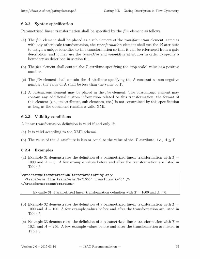
http://flowcyt.sf.net/gating/latest.pdf Gating-ML – Gating Description in Flow Cytometry
6.2.2 Syntax specification
Parametrized linear transformation shall be specified by the flin element as follows:
(a) The flin element shall be placed as a sub element of the transformation element; same aswith any other scale transformation, the transformation element shall use the id attributeto assign a unique identifier to this transformation so that it can be referenced from a gatedescription, and it may use the boundMin and boundMax attributes in order to specify aboundary as described in section 6.1.
(b) The flin element shall contain the T attribute specifying the “top scale” value as a positivenumber.
(c) The flin element shall contain the A attribute specifying the A constant as non-negativenumber; the value of A shall be less than the value of T.
(d) A custom info element may be placed in the flin element. The custom info element maycontain any additional custom information related to this transformation; the format ofthis element (i.e., its attributes, sub elements, etc.) is not constrained by this specificationas long as the document remains a valid XML.
6.2.3 Validity conditions
A linear transformation definition is valid if and only if:
(a) It is valid according to the XML schema.
(b) The value of the A attribute is less or equal to the value of the T attribute, i.e., A ≤ T .
6.2.4 Examples
(a) Example 31 demonstrates the definition of a parametrized linear transformation with T =1000 and A = 0. A few example values before and after the transformation are listed inTable 5.
<transforms:transformation transforms:id="myLin">
<transforms:flin transforms:T="1000" transforms:A="0" />
</transforms:transformation>
Example 31: Parametrized linear transformation definition with T = 1000 and A = 0.
(b) Example 32 demonstrates the definition of a parametrized linear transformation with T =1000 and A = 100. A few example values before and after the transformation are listed inTable 5.
(c) Example 33 demonstrates the definition of a parametrized linear transformation with T =1024 and A = 256. A few example values before and after the transformation are listed inTable 5.
Version 2.0 – 2015-03-16 — ISAC Recommendation — 65

http://flowcyt.sf.net/gating/latest.pdf Gating-ML – Gating Description in Flow Cytometry
x flin(x,1000,0) flin(x,1000,100) flin(x,1024,256) bound(flin(x,1000,0),0,0.8)
−100 −0.1 0.0 0.121875 0−10 −0.01 ≈ 0.081818 0.1921875 00 0.0 ≈ 0.090909 0.2 010 0.01 0.1 0.2078125 0.01100 0.1 ≈ 0.181818 0.278125 0.1120 0.12 0.2 0.29375 0.12890 0.89 0.9 0.8953125 0.81000 1.0 1.0 0.98125 0.8
Table 5: Sample values of the flin transformation with various T and A.
<transforms:transformation transforms:id="myLin2">
<transforms:flin transforms:T="1000" transforms:A="100" />
</transforms:transformation>
Example 32: Parametrized linear transformation definition with T = 1000 and A = 100.
<transforms:transformation transforms:id="myLin3">
<transforms:flin transforms:T="1024" transforms:A="256" />
</transforms:transformation>
Example 33: Parametrized linear transformation definition with T = 1024 and A = 256.
<transforms:transformation transforms:id="myBoundLin3"
transforms:boundMin="0" transforms:boundMax="0.8">
<transforms:flin transforms:T="1000" transforms:A="0" />
</transforms:transformation>
Example 34: Parametrized linear transformation definition with a boundary.
(d) Example 34 demonstrates the definition of the same linear transformation as in example31; however, a boundary is used to restrict the results of this transformation to the [0, 0.8]interval. A few example values before and after the transformation are listed in Table 5.
6.3 Parametrized logarithmic transformation – flog
6.3.1 Definition
Parametrized logarithmic transformation (flog) is defined by the following function:
flog(x, T,M) =1
Mlog10(
x
T) + 1
where
• log10 is the common logarithm (i.e, logarithm with base 10).
• x ∈ R, x > 0 is the value that is being transformed (an FCS dimension value). Typically,x ≤ T although the transformation function is also defined for x > T .
Version 2.0 – 2015-03-16 — ISAC Recommendation — 66
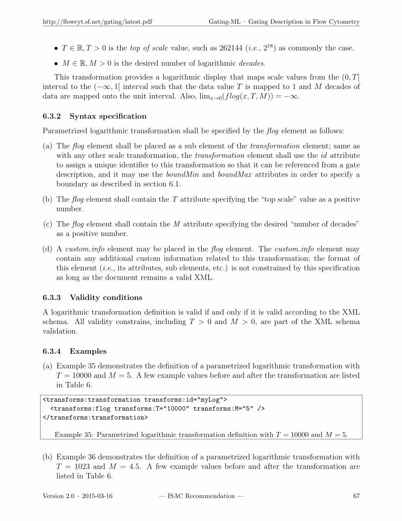
http://flowcyt.sf.net/gating/latest.pdf Gating-ML – Gating Description in Flow Cytometry
• T ∈ R, T > 0 is the top of scale value, such as 262144 (i.e., 218) as commonly the case.
• M ∈ R,M > 0 is the desired number of logarithmic decades.
This transformation provides a logarithmic display that maps scale values from the (0, T ]interval to the (−∞, 1] interval such that the data value T is mapped to 1 and M decades ofdata are mapped onto the unit interval. Also, limx→0(flog(x, T,M)) = −∞.
6.3.2 Syntax specification
Parametrized logarithmic transformation shall be specified by the flog element as follows:
(a) The flog element shall be placed as a sub element of the transformation element; same aswith any other scale transformation, the transformation element shall use the id attributeto assign a unique identifier to this transformation so that it can be referenced from a gatedescription, and it may use the boundMin and boundMax attributes in order to specify aboundary as described in section 6.1.
(b) The flog element shall contain the T attribute specifying the “top scale” value as a positivenumber.
(c) The flog element shall contain the M attribute specifying the desired “number of decades”as a positive number.
(d) A custom info element may be placed in the flog element. The custom info element maycontain any additional custom information related to this transformation; the format ofthis element (i.e., its attributes, sub elements, etc.) is not constrained by this specificationas long as the document remains a valid XML.
6.3.3 Validity conditions
A logarithmic transformation definition is valid if and only if it is valid according to the XMLschema. All validity constrains, including T > 0 and M > 0, are part of the XML schemavalidation.
6.3.4 Examples
(a) Example 35 demonstrates the definition of a parametrized logarithmic transformation withT = 10000 and M = 5. A few example values before and after the transformation are listedin Table 6.
<transforms:transformation transforms:id="myLog">
<transforms:flog transforms:T="10000" transforms:M="5" />
</transforms:transformation>
Example 35: Parametrized logarithmic transformation definition with T = 10000 and M = 5.
(b) Example 36 demonstrates the definition of a parametrized logarithmic transformation withT = 1023 and M = 4.5. A few example values before and after the transformation arelisted in Table 6.
Version 2.0 – 2015-03-16 — ISAC Recommendation — 67
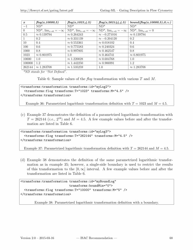
http://flowcyt.sf.net/gating/latest.pdf Gating-ML – Gating Description in Flow Cytometry
x flog(x,10000,5) flog(x,1023,4.5) flog(x,262144,4.5) bound(flog(x,10000,5),0,∞)
−1 ND* ND* ND* ND*0 ND*, limx→0 = −∞ ND*, limx→0 = −∞ ND*, limx→0 = −∞ ND*, limx→0 = 00.5 ≈ 0.139794 ≈ 0.264243 ≈ −0.271016 ≈ 0.1397941 0.2 ≈ 0.331139 ≈ −0.204120 0.210 0.4 ≈ 0.553361 ≈ 0.018102 0.4100 0.6 ≈ 0.775583 ≈ 0.240324 0.61000 0.8 ≈ 0.997805 ≈ 0.462547 0.81023 ≈ 0.801975 1.0 ≈ 0.464741 ≈ 0.80197510000 1.0 ≈ 1.220028 ≈ 0.684768 1.0100000 1.2 ≈ 1.442250 ≈ 0.906991 1.2262144 ≈ 1.283708 ≈ 1.535259 1.0 ≈ 1.283708
*ND stands for “Not Defined”.
Table 6: Sample values of the flog transformation with various T and M .
<transforms:transformation transforms:id="myLog2">
<transforms:flog transforms:T="1023" transforms:M="4.5" />
</transforms:transformation>
Example 36: Parametrized logarithmic transformation definition with T = 1023 and M = 4.5.
(c) Example 37 demonstrates the definition of a parametrized logarithmic transformation withT = 262144 (i.e., 218) and M = 4.5. A few example values before and after the transfor-mation are listed in Table 6.
<transforms:transformation transforms:id="myLog3">
<transforms:flog transforms:T="262144" transforms:M="4.5" />
</transforms:transformation>
Example 37: Parametrized logarithmic transformation definition with T = 262144 and M = 4.5.
(d) Example 38 demonstrates the definition of the same parametrized logarithmic transfor-mation as in example 35; however, a single-side boundary is used to restrict the resultsof this transformation to the [0,∞] interval. A few example values before and after thetransformation are listed in Table 6.
<transforms:transformation transforms:id="myBoundLog"
transforms:boundMin="0">
<transforms:flog transforms:T="10000" transforms:M="5" />
</transforms:transformation>
Example 38: Parametrized logarithmic transformation definition with a boundary.
Version 2.0 – 2015-03-16 — ISAC Recommendation — 68
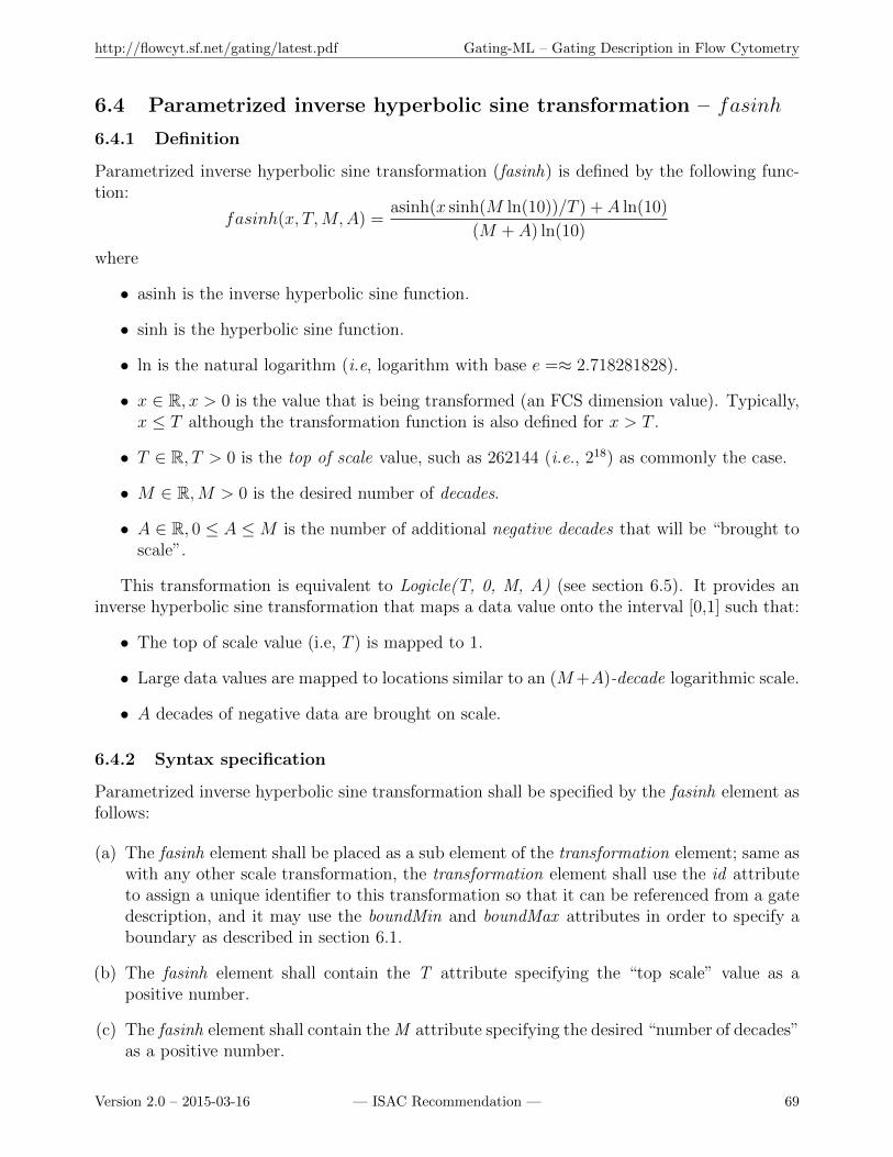
http://flowcyt.sf.net/gating/latest.pdf Gating-ML – Gating Description in Flow Cytometry
6.4 Parametrized inverse hyperbolic sine transformation – fasinh
6.4.1 Definition
Parametrized inverse hyperbolic sine transformation (fasinh) is defined by the following func-tion:
fasinh(x, T,M,A) =asinh(x sinh(M ln(10))/T ) + A ln(10)
(M + A) ln(10)
where
• asinh is the inverse hyperbolic sine function.
• sinh is the hyperbolic sine function.
• ln is the natural logarithm (i.e, logarithm with base e =≈ 2.718281828).
• x ∈ R, x > 0 is the value that is being transformed (an FCS dimension value). Typically,x ≤ T although the transformation function is also defined for x > T .
• T ∈ R, T > 0 is the top of scale value, such as 262144 (i.e., 218) as commonly the case.
• M ∈ R,M > 0 is the desired number of decades.
• A ∈ R, 0 ≤ A ≤M is the number of additional negative decades that will be “brought toscale”.
This transformation is equivalent to Logicle(T, 0, M, A) (see section 6.5). It provides aninverse hyperbolic sine transformation that maps a data value onto the interval [0,1] such that:
• The top of scale value (i.e, T ) is mapped to 1.
• Large data values are mapped to locations similar to an (M+A)-decade logarithmic scale.
• A decades of negative data are brought on scale.
6.4.2 Syntax specification
Parametrized inverse hyperbolic sine transformation shall be specified by the fasinh element asfollows:
(a) The fasinh element shall be placed as a sub element of the transformation element; same aswith any other scale transformation, the transformation element shall use the id attributeto assign a unique identifier to this transformation so that it can be referenced from a gatedescription, and it may use the boundMin and boundMax attributes in order to specify aboundary as described in section 6.1.
(b) The fasinh element shall contain the T attribute specifying the “top scale” value as apositive number.
(c) The fasinh element shall contain the M attribute specifying the desired “number of decades”as a positive number.
Version 2.0 – 2015-03-16 — ISAC Recommendation — 69
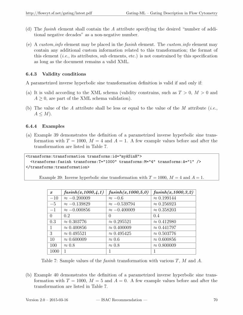
http://flowcyt.sf.net/gating/latest.pdf Gating-ML – Gating Description in Flow Cytometry
(d) The fasinh element shall contain the A attribute specifying the desired “number of addi-tional negative decades” as a non-negative number.
(e) A custom info element may be placed in the fasinh element. The custom info element maycontain any additional custom information related to this transformation; the format ofthis element (i.e., its attributes, sub elements, etc.) is not constrained by this specificationas long as the document remains a valid XML.
6.4.3 Validity conditions
A parametrized inverse hyperbolic sine transformation definition is valid if and only if:
(a) It is valid according to the XML schema (validity constrains, such as T > 0, M > 0 andA ≥ 0, are part of the XML schema validation).
(b) The value of the A attribute shall be less or equal to the value of the M attribute (i.e.,A ≤M).
6.4.4 Examples
(a) Example 39 demonstrates the definition of a parametrized inverse hyperbolic sine trans-formation with T = 1000, M = 4 and A = 1. A few example values before and after thetransformation are listed in Table 7.
<transforms:transformation transforms:id="myASinH">
<transforms:fasinh transforms:T="1000" transforms:M="4" transforms:A="1" />
</transforms:transformation>
Example 39: Inverse hyperbolic sine transformation with T = 1000, M = 4 and A = 1.
x fasinh(x,1000,4,1) fasinh(x,1000,5,0) fasinh(x,1000,3,2)
−10 ≈ −0.200009 ≈ −0.6 ≈ 0.199144−5 ≈ −0.139829 ≈ −0.539794 ≈ 0.256923−1 ≈ −0.000856 ≈ −0.400009 ≈ 0.3582030 0.2 0 0.40.3 ≈ 0.303776 ≈ 0.295521 ≈ 0.4129801 ≈ 0.400856 ≈ 0.400009 ≈ 0.4417973 ≈ 0.495521 ≈ 0.495425 ≈ 0.50377610 ≈ 0.600009 ≈ 0.6 ≈ 0.600856100 ≈ 0.8 ≈ 0.8 ≈ 0.8000091000 1 1 1
Table 7: Sample values of the fasinh transformation with various T , M and A.
(b) Example 40 demonstrates the definition of a parametrized inverse hyperbolic sine trans-formation with T = 1000, M = 5 and A = 0. A few example values before and after thetransformation are listed in Table 7.
Version 2.0 – 2015-03-16 — ISAC Recommendation — 70

http://flowcyt.sf.net/gating/latest.pdf Gating-ML – Gating Description in Flow Cytometry
<transforms:transformation transforms:id="myASinH2">
<transforms:fasinh transforms:T="1000" transforms:M="5" transforms:A="0" />
</transforms:transformation>
Example 40: Inverse hyperbolic sine transformation with T = 1000, M = 5 and A = 0.
(c) Example 41 demonstrates the definition of a parametrized inverse hyperbolic sine trans-formation with T = 1000, M = 3 and A = 2. A few example values before and after thetransformation are listed in Table 7.
<transforms:transformation transforms:id="myASinH3">
<transforms:fasinh transforms:T="1000" transforms:M="3" transforms:A="2" />
</transforms:transformation>
Example 41: Inverse hyperbolic sine transformation with T = 1000, M = 3 and A = 2.
(d) Example 29 in section 6.1.5 (b) demonstrates the definition of an inverse hyperbolic sinetransformation with a boundary.
6.5 Logicle transformation
6.5.1 Definition
Logicle transformation as published by Moore and Parks [22] is defined by the following function:
logicle(x, T,W,M,A) = root(B(y, T,W,M,A)− x)
and B is a modified biexponential function
B(y, T,W,M,A) = aeby − ce−dy − f
where
• x ∈ R is the value that is being transformed (an FCS dimension value). Typically, x ≤ Talthough the transformation function is also defined for x > T .
• y ∈ R is the result of the transformation.
• T ∈ R, T > 0 is the top of scale value.
• M ∈ R,M > 0 is the number of decades that the true logarithmic scale approached atthe high end of the Logicle scale would cover in the plot range.
• W ∈ R, 0 ≤ W ≤ M/2 is the number of such decades in the approximately linearregion. The choice of W = M/2 specifies a scale that is essentially linear over the wholerange except for a small region of large data values. For situations in which values ofW approaching M/2 might be chosen, ordinary linear display scales will usually be moreappropriate. The choice of W = 0 gives the hyperbolic sine function.
Version 2.0 – 2015-03-16 — ISAC Recommendation — 71
http://flowcyt.sf.net/gating/latest.pdf Gating-ML – Gating Description in Flow Cytometry
• A ∈ R,−W ≤ A ≤M − 2W is the number of additional decades of negative data valuesto be included.
• root is a standard root finding algorithm (e.g., Newton’s method) that finds y such asB(y, T,W,M,A) = x.
and a, b, c, d and f are defined by means of T , W , M , A, w, x0, x1, x2, ca and fa as
w =W
M + A
x2 =A
M + A
x1 = x2 + w
x0 = x2 + 2w
b = (M + A) ln(10)
d is a constant so that2(ln(d)− ln(b)) + w(d+ b) = 0
given b and wand
ca = ex0(b+d)
fa = ebx1 − caedx1
a =T
eb − fa − caed
c = caa
f = faa
The Logicle scale is the inverse of a modified biexponential function. It provides a Logicledisplay that maps scale values onto the [0, 1] interval such that the data value T is mapped to1, large data values are mapped to locations similar to an (M + A)-decade logarithmic scale,and A decades of negative data are brought on scale. For implementation purposes, it is recom-mended to follow guidance in [22] and see the reference implementation rather than encodingthe transformation directly based on the presented formulas since a naıve implementation willlikely suffer from significant round off errors.
The standard Logicle scale (i.e., with A = 0) is defined, so that the most negative value onscale has the same absolute value as the most positive data value in what can be considered thequasilinear region of the scale. The zero data value is at the center of the quasilinear region, andversions differing only in the value of W approach the same logarithmic behavior at the highend. It has the desirable feature of making the scale position of large data values essentially thesame among Logicle displays with different values of W and closely matching a true logarithmicdisplay with the same value for M , which facilitates visual comparison of distributions.
In a few situations, altering the negative data range to be greater or less than the nominalquasilinear region of a standard Logicle transformation may be desirable. This may be accom-plished by altering the A parameter that specifies additional decades of negative data values.
Version 2.0 – 2015-03-16 — ISAC Recommendation — 72
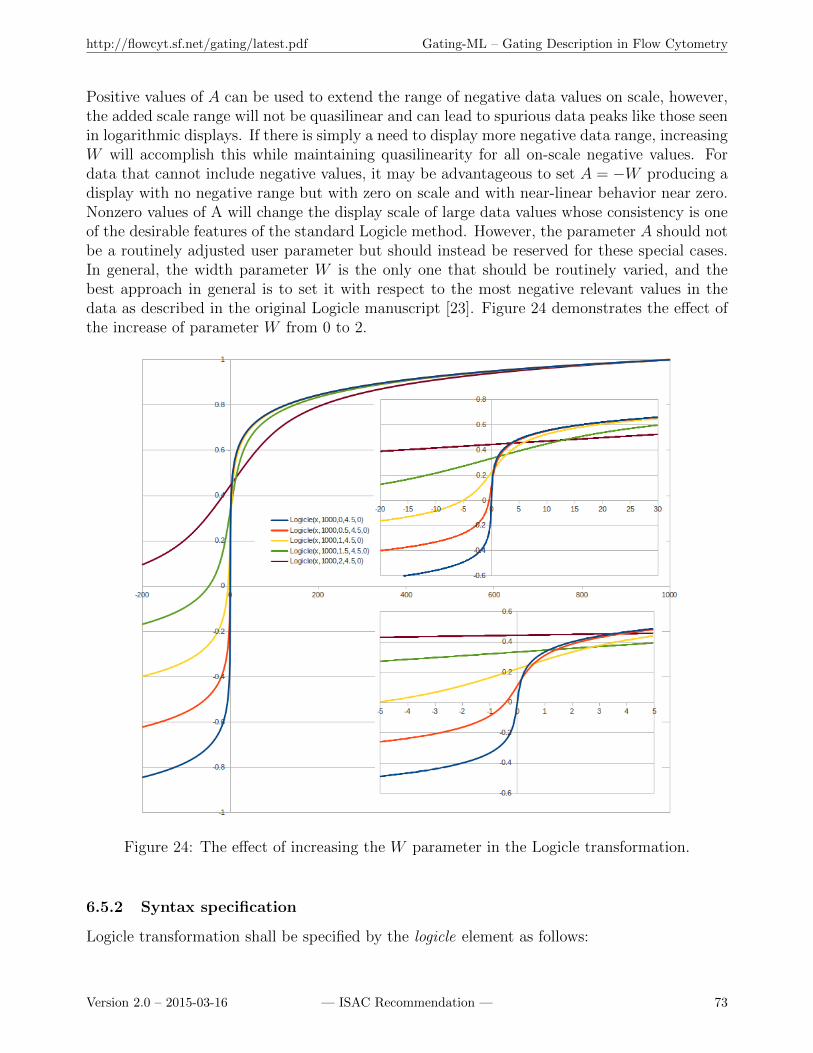
http://flowcyt.sf.net/gating/latest.pdf Gating-ML – Gating Description in Flow Cytometry
Positive values of A can be used to extend the range of negative data values on scale, however,the added scale range will not be quasilinear and can lead to spurious data peaks like those seenin logarithmic displays. If there is simply a need to display more negative data range, increasingW will accomplish this while maintaining quasilinearity for all on-scale negative values. Fordata that cannot include negative values, it may be advantageous to set A = −W producing adisplay with no negative range but with zero on scale and with near-linear behavior near zero.Nonzero values of A will change the display scale of large data values whose consistency is oneof the desirable features of the standard Logicle method. However, the parameter A should notbe a routinely adjusted user parameter but should instead be reserved for these special cases.In general, the width parameter W is the only one that should be routinely varied, and thebest approach in general is to set it with respect to the most negative relevant values in thedata as described in the original Logicle manuscript [23]. Figure 24 demonstrates the effect ofthe increase of parameter W from 0 to 2.
Figure 24: The effect of increasing the W parameter in the Logicle transformation.
6.5.2 Syntax specification
Logicle transformation shall be specified by the logicle element as follows:
Version 2.0 – 2015-03-16 — ISAC Recommendation — 73
http://flowcyt.sf.net/gating/latest.pdf Gating-ML – Gating Description in Flow Cytometry
(a) The logicle element shall be placed as a sub element of the transformation element; same aswith any other scale transformation, the transformation element shall use the id attributeto assign a unique identifier to this transformation so that it can be referenced from a gatedescription, and it may use the boundMin and boundMax attributes in order to specify aboundary as described in section 6.1.
(b) The logicle element shall contain the T attribute specifying the “top scale” value as apositive number.
(c) The logicle element shall contain the M attribute specifying the desired “number of decades”as a positive number.
(d) The logicle element shall contain the W attribute specifying the number of such decadesin the approximately linear region. The value of the W attribute shall be greater thanor equal to zero and less than or equal to the value of the M attribute divided by 2 (i.e.,0 ≤ W ≤M/2).
(e) The logicle element shall contain the A attribute specifying the desired “number of addi-tional negative decades”. The value of the A attribute shall be greater than or equal tominus of the value of the W attribute and less than or equal to the value of the M attributeminus twice the value of the W attribute (i.e., −W ≤ A ≤M − 2W ).
(f) A custom info element may be placed in the logicle element. The custom info element maycontain any additional custom information related to this transformation; the format ofthis element (i.e., its attributes, sub elements, etc.) is not constrained by this specificationas long as the document remains a valid XML.
6.5.3 Validity conditions
A Logicle transformation definition is valid if and only if:
(a) It is valid according to the XML schema.
(b) The value of the W attribute shall be greater than or equal to zero and less than or equalto the value of the M attribute divided by 2 (i.e., 0 ≤ W ≤M/2).
(c) The value of the A attribute shall be greater than or equal to minus of the value of the Wattribute and less than or equal to the value of the M attribute minus twice the value ofthe W attribute (i.e., −W ≤ A ≤M − 2W ).
Constrains on the T , W , M and A attribute values are the same as with the Hyperlog trans-formation except for the value of W , which shall be greater of equal to 0 for Logicle, while itshall be greater than 0 for Hyperlog (see section 6.6.3).
6.5.4 Examples
(a) Example 42 demonstrates the definition of a Logicle transformation with T = 1000, W = 1,M = 4, and A = 0. A few example values before and after the transformation are listed inTable 8.
Version 2.0 – 2015-03-16 — ISAC Recommendation — 74
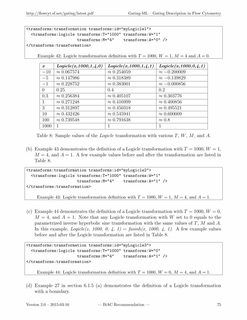
http://flowcyt.sf.net/gating/latest.pdf Gating-ML – Gating Description in Flow Cytometry
<transforms:transformation transforms:id="myLogicle1">
<transforms:logicle transforms:T="1000" transforms:W="1"
transforms:M="4" transforms:A="0" />
</transforms:transformation>
Example 42: Logicle transformation definition with T = 1000, W = 1, M = 4 and A = 0.
x Logicle(x,1000,1,4,0) Logicle(x,1000,1,4,1) Logicle(x,1000,0,4,1)
−10 ≈ 0.067574 ≈ 0.254059 ≈ −0.200009−5 ≈ 0.147986 ≈ 0.318389 ≈ −0.139829−1 ≈ 0.228752 ≈ 0.383001 ≈ −0.0008560 0.25 0.4 0.20.3 ≈ 0.256384 ≈ 0.405107 ≈ 0.3037761 ≈ 0.271248 ≈ 0.416999 ≈ 0.4008563 ≈ 0.312897 ≈ 0.450318 ≈ 0.49552110 ≈ 0.432426 ≈ 0.545941 ≈ 0.600009100 ≈ 0.739548 ≈ 0.791638 ≈ 0.81000 1 1 1
Table 8: Sample values of the Logicle transformation with various T , W , M , and A.
(b) Example 43 demonstrates the definition of a Logicle transformation with T = 1000, W = 1,M = 4, and A = 1. A few example values before and after the transformation are listed inTable 8.
<transforms:transformation transforms:id="myLogicle2">
<transforms:logicle transforms:T="1000" transforms:W="1"
transforms:M="4" transforms:A="1" />
</transforms:transformation>
Example 43: Logicle transformation definition with T = 1000, W = 1, M = 4, and A = 1.
(c) Example 44 demonstrates the definition of a Logicle transformation with T = 1000, W = 0,M = 4, and A = 1. Note that any Logicle transformation with W set to 0 equals to theparametrized inverse hyperbolic sine transformation with the same values of T , M and A.In this example, Logicle(x, 1000, 0, 4, 1) = fasinh(x, 1000, 4, 1). A few example valuesbefore and after the Logicle transformation are listed in Table 8.
<transforms:transformation transforms:id="myLogicle3">
<transforms:logicle transforms:T="1000" transforms:W="0"
transforms:M="4" transforms:A="1" />
</transforms:transformation>
Example 44: Logicle transformation definition with T = 1000, W = 0, M = 4, and A = 1.
(d) Example 27 in section 6.1.5 (a) demonstrates the definition of a Logicle transformationwith a boundary.
Version 2.0 – 2015-03-16 — ISAC Recommendation — 75
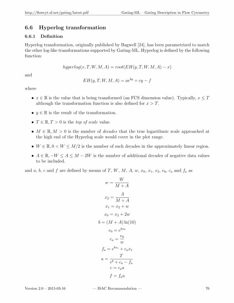
http://flowcyt.sf.net/gating/latest.pdf Gating-ML – Gating Description in Flow Cytometry
6.6 Hyperlog transformation
6.6.1 Definition
Hyperlog transformation, originally published by Bagwell [24], has been parametrized to matchthe other log-like transformations supported by Gating-ML. Hyperlog is defined by the followingfunction:
hyperlog(x, T,W,M,A) = root(EH(y, T,W,M,A)− x)
andEH(y, T,W,M,A) = aeby + cy − f
where
• x ∈ R is the value that is being transformed (an FCS dimension value). Typically, x ≤ Talthough the transformation function is also defined for x > T .
• y ∈ R is the result of the transformation.
• T ∈ R, T > 0 is the top of scale value.
• M ∈ R,M > 0 is the number of decades that the true logarithmic scale approached atthe high end of the Hyperlog scale would cover in the plot range.
• W ∈ R, 0 < W ≤M/2 is the number of such decades in the approximately linear region.
• A ∈ R,−W ≤ A ≤M − 2W is the number of additional decades of negative data valuesto be included.
and a, b, c and f are defined by means of T , W , M , A, w, x0, x1, x2, e0, ca and fa as
w =W
M + A
x2 =A
M + A
x1 = x2 + w
x0 = x2 + 2w
b = (M + A) ln(10)
e0 = ebx0
ca =e0w
fa = ebx1 + cax1
a =T
eb + ca − fac = caa
f = faa
Version 2.0 – 2015-03-16 — ISAC Recommendation — 76

http://flowcyt.sf.net/gating/latest.pdf Gating-ML – Gating Description in Flow Cytometry
Figure 25: The effect of increasing the W parameter in the Hyperlog transformation.
As with the Logicle scale, generally only the width parameter W (i.e., the number of decadesin the approximately linear region) should be routinely varied and may also be set as describedin the original Logicle manuscript [23]. Figure 25 demonstrates the effect of the increase ofparameter W from 0.01 to 2.
For implementation purposes, it is highly recommended to follow the reference implemen-tation rather than encoding the transformation directly based on the presented formulas sincea naıve implementation will likely suffer from significant round off errors.
6.6.2 Syntax specification
Hyperlog transformation shall be specified by the hyperlog element as follows:
(a) The hyperlog element shall be placed as a sub element of the transformation element; sameas with any other scale transformation, the transformation element shall use the id attributeto assign a unique identifier to this transformation so that it can be referenced from a gatedescription, and it may use the boundMin and boundMax attributes in order to specify aboundary as described in section 6.1.
(b) The hyperlog element shall contain the T attribute specifying the “top scale” value as apositive number.
(c) The hyperlog element shall contain the M attribute specifying the desired “number ofdecades” as a positive number.
Version 2.0 – 2015-03-16 — ISAC Recommendation — 77
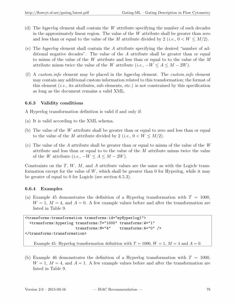
http://flowcyt.sf.net/gating/latest.pdf Gating-ML – Gating Description in Flow Cytometry
(d) The hyperlog element shall contain the W attribute specifying the number of such decadesin the approximately linear region. The value of the W attribute shall be greater than zeroand less than or equal to the value of the M attribute divided by 2 (i.e., 0 < W ≤M/2).
(e) The hyperlog element shall contain the A attribute specifying the desired “number of ad-ditional negative decades”. The value of the A attribute shall be greater than or equalto minus of the value of the W attribute and less than or equal to to the value of the Mattribute minus twice the value of the W attribute (i.e., −W ≤ A ≤M − 2W ).
(f) A custom info element may be placed in the hyperlog element. The custom info elementmay contain any additional custom information related to this transformation; the format ofthis element (i.e., its attributes, sub elements, etc.) is not constrained by this specificationas long as the document remains a valid XML.
6.6.3 Validity conditions
A Hyperlog transformation definition is valid if and only if:
(a) It is valid according to the XML schema.
(b) The value of the W attribute shall be greater than or equal to zero and less than or equalto the value of the M attribute divided by 2 (i.e., 0 < W ≤M/2).
(c) The value of the A attribute shall be greater than or equal to minus of the value of the Wattribute and less than or equal to to the value of the M attribute minus twice the valueof the W attribute (i.e., −W ≤ A ≤M − 2W ).
Constraints on the T , W , M , and A attribute values are the same as with the Logicle trans-formation except for the value of W , which shall be greater than 0 for Hyperlog, while it maybe greater of equal to 0 for Logicle (see section 6.5.3).
6.6.4 Examples
(a) Example 45 demonstrates the definition of a Hyperlog transformation with T = 1000,W = 1, M = 4, and A = 0. A few example values before and after the transformation arelisted in Table 9.
<transforms:transformation transforms:id="myHyperlog1">
<transforms:hyperlog transforms:T="1000" transforms:W="1"
transforms:M="4" transforms:A="0" />
</transforms:transformation>
Example 45: Hyperlog transformation definition with T = 1000, W = 1, M = 4 and A = 0.
(b) Example 46 demonstrates the definition of a Hyperlog transformation with T = 1000,W = 1, M = 4, and A = 1. A few example values before and after the transformation arelisted in Table 9.
Version 2.0 – 2015-03-16 — ISAC Recommendation — 78
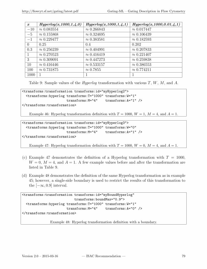
http://flowcyt.sf.net/gating/latest.pdf Gating-ML – Gating Description in Flow Cytometry
x Hyperlog(x,1000,1,4,0) Hyperlog(x,1000,1,4,1) Hyperlog(x,1000,0.01,4,1)
−10 ≈ 0.083554 ≈ 0.266843 ≈ 0.017447−5 ≈ 0.155868 ≈ 0.324695 ≈ 0.106439−1 ≈ 0.229477 ≈ 0.383581 ≈ 0.1825930 0.25 0.4 0.2020.3 ≈ 0.256239 ≈ 0.404991 ≈ 0.2078331 ≈ 0.270523 ≈ 0.416419 ≈ 0.2214073 ≈ 0.309091 ≈ 0.447273 ≈ 0.25983810 ≈ 0.416446 ≈ 0.533157 ≈ 0.386553100 ≈ 0.731875 ≈ 0.7855 ≈ 0.7742111000 1 1 1
Table 9: Sample values of the Hyperlog transformation with various T , W , M , and A.
<transforms:transformation transforms:id="myHyperlog2">
<transforms:hyperlog transforms:T="1000" transforms:W="1"
transforms:M="4" transforms:A="1" />
</transforms:transformation>
Example 46: Hyperlog transformation definition with T = 1000, W = 1, M = 4, and A = 1.
<transforms:transformation transforms:id="myHyperlog3">
<transforms:hyperlog transforms:T="1000" transforms:W="0"
transforms:M="4" transforms:A="1" />
</transforms:transformation>
Example 47: Hyperlog transformation definition with T = 1000, W = 0, M = 4, and A = 1.
(c) Example 47 demonstrates the definition of a Hyperlog transformation with T = 1000,W = 0, M = 4, and A = 1. A few example values before and after the transformation arelisted in Table 9.
(d) Example 48 demonstrates the definition of the same Hyperlog transformation as in example45; however, a single-side boundary is used to restrict the results of this transformation tothe [−∞, 0.9] interval.
<transforms:transformation transforms:id="myBoundHyperlog"
transforms:boundMax="0.9">
<transforms:hyperlog transforms:T="1000" transforms:W="1"
transforms:M="4" transforms:A="0" />
</transforms:transformation>
Example 48: Hyperlog transformation definition with a boundary.
Version 2.0 – 2015-03-16 — ISAC Recommendation — 79
http://flowcyt.sf.net/gating/latest.pdf Gating-ML – Gating Description in Flow Cytometry
7 Compensation description
7.1 Definition
In flow cytometry, the emission spectral overlap of fluorescent labels makes it usually necessaryto correct detected signals before using the values as a basis for other analyses. Fluorescencecompensation [25] is the process by which the total detected signal is corrected for the spectraloverlap to yield an estimate of the actual amount of each dye. This process is described by thestandard compensation computing algorithm in section 7.6.1.
Recently, novel instruments have been introduced measuring the fluorescence spectrum withgreater detail by many more detectors than dyes in the sample. The originally square spillovermatrix became a non-square matrix describing the relative amount of fluorescence detected byeach of the detectors for each of the dyes in the sample. The process of compensation turnedhereby into the problem of spectral unmixing as described in Section 7.6.2.
7.2 Syntax specification
Fluorescence compensation shall be described by a spectrum matrix. The term “spectrum”has been introduced as applicable for both the traditional compensation as well as spectralunmixing. Here, we describe the syntax of this description. The semantics is further explainedin section 7.3. A n × m spectrum matrix, n ∈ N,m ∈ N, n ≤ m (historically, n = m, seesection 7.3) shall be described by the spectrumMatrix element placed at the top level in theGating-ML file (i.e., as a sub element of the Gating-ML element) as follows:
(a) The spectrumMatrix element shall use the id attribute to globally identify the spectrum(spillover) matrix by assigning it a unique identifier.
(b) The spectrumMatrix element may use the Boolean matrix-inverted-already attribute toexplicitly specify whether the matrix has been inverted already. The default value of thisattribute is false, in which case the matrix is considered to be the spectrum (spillover)matrix. If the matrix-inverted-already is set to true then the matrix is considered to be the(pseudo)inverse of the spectrum (spillover) matrix.
(c) A custom info element may be placed at the beginning of the spectrumMatrix element.The custom info element may contain any additional custom information related to thisspectrum matrix; the format of this element (i.e., its attributes, sub elements, etc.) is notconstrained by this specification as long as the document remains a valid XML.
(d) A fluorochromes element shall be placed at the beginning of the spectrumMatrix elementor right after the custom info element if the custom info element is used.
(e) n fcs-dimension elements shall be placed as sub elements of the fluorochromes element.
(f) Each fcs-dimension element shall include a name attribute. These names shall be uniquewithin the fluorochromes element as well as the detectors elements, i.e., no fluorochromename shall be equal to any detector name, or to any other fluorochrome name, and nodetector name shall be equal to any fluorochrome name, or to any other detector namewithin the matrix definition. Names assigned to fluorochromes (rows) of the matrix shall
Version 2.0 – 2015-03-16 — ISAC Recommendation — 80
http://flowcyt.sf.net/gating/latest.pdf Gating-ML – Gating Description in Flow Cytometry
be used to reference resulting gating dimensions in gates that are also referencing thisspectrum (spillover) matrix.
(g) A detectors element shall be placed after the fluorochromes element.
(h) m fcs-dimension elements shall be placed as sub elements of the detectors element.
(i) Each fcs-dimension element shall include a name attribute to reference an FCS dimensionas described in section 4.1. The names shall be unique within the detectors element as wellas the fluorochromes element, i.e., no detector name shall be equal to any fluorochromename.
(j) The spectrum shall be written in the row major order as follows:
(i) n spectrum elements shall follow as sub elements of the spectrumMatrix element af-ter the fcs-dimensions element; each spectrum element corresponds to a row of thespectrum (spillover) matrix.
(ii) m coefficient elements shall be included as sub elements of each of the spectrumelements.
(iii) Each coefficient element shall specify a numeric spectrum/spillover coefficient valueusing the value attribute.
7.3 Semantic specification
Assuming the matrix-inverted-already is set to false (or the attribute is not present) then let Mbe a n×m spectrum (spillover) matrix (n ∈ N,m ∈ N, n ≤ m). Let Xf be the i-th argumentspecified within the fluorochromes element. Let Yd be the j-th argument specified within thedetectors element. Let S be the i-th spectrum element within the definition of spectrum matrixM . Let C be the j-th coefficient element within the spectrum element S. Let V be the valueof the value attribute of C. Example 49 demonstrates the XML representation of the spectrummatrix M as described.
For typical spillover case, the entry shown in example 49 means that V is the spillovercoefficient from Xf to Yd. The spillover coefficient from Xf to Yd is the ratio of the amountof signal in the Yd channel to the amount of signal in the “primary” Xf channel for particlescarrying only the Xf dye. For spectral unmixing cases, the entry shown in example 49 meansthat V is the spectrum coefficient from Xf to Yd. The spectrum coefficient from Xf to Yd isthe relative amount of signal on the Yd detector for particles carrying only the Xf dye.
If the matrix-inverted-already is set to true, then the matrix is considered to be the (pseudo)inverseof the spectrum (spillover) matrix. Typical fluorescence compensation (or spectral unmixing)algorithms include the computation of the (pseudo)inverse of the spectrum (spillover) matrix.This calculation does not need to be performed if the matrix is (pseudo)inverted already.
7.4 Validity conditions
A spectrum matrix definition is valid if and only if:
(a) It is valid according to the XML schema.
Version 2.0 – 2015-03-16 — ISAC Recommendation — 81

http://flowcyt.sf.net/gating/latest.pdf Gating-ML – Gating Description in Flow Cytometry
<transforms:spectrumMatrix transforms:id="M"
transforms:matrix-inverted-already="false">
<transforms:fluorochromes>
...
<!-- i-th fcs-dimension element within the fluorochromes element -->
<data-type:fcs-dimension data-type:name="Xf" />
...
</transforms:fluorochromes>
<transforms:detectors>
...
<!-- j-th fcs-dimension element within the detectors element -->
<data-type:fcs-dimension data-type:name="Yd" />
...
</transforms:detectors>
...
<!-- i-th spectrum element within the spectrumMatrix element -->
<transforms:spectrum>
...
<!-- j-th coefficient element within the spectrum element -->
<transforms:coefficient transforms:value="V" />
...
</transforms:spectrum>
...
</transforms:spectrumMatrix>
Example 49: Definition of a spectrum (spillover) matrix.
(b) All the listed names are unique; detector names shall reference list mode data parameters,fluorochrome names shall be used to name compensated (unmixed) dimensions.
(c) The definition is a proper n×mmatrix, n ∈ N,m ∈ N, n ≤ m, i.e., there are n fcs dimensionelements as sub elements of the fluorochromes element, m fcs dimension elements as subelements of the detectors element and n spectrum elements, each spectrum element includingm coefficient elements.
(d) The rows of matrix M (corresponding to the individual fluorochrome spectra) shall belinearly independent, i.e., no fluorochrome spectra may occur twice, which is to say, thematrix M is non-singular (invertible) in the square case and that the pseudo inverse hasfull rank otherwise.
There are no additional validity conditions that would ensure a “normalized” form of thematrix. In conventional compensation, there is an independent detector for each channel.Therefore, the best practice is to adjust the voltages on the detectors to bring a reference in-tensity particle to standard operating conditions, which fixes the scale between some amount ofdye and the measurements on the dedicated detector. The point of normalizing to unity on thediagonal on conventional compensation is that it leaves this scale unchanged on compensateddata. There is no direct equivalent for spectrum based instruments. The normalization to sumof one means that all the unmixed data will be scaled proportional to the total signal on all
Version 2.0 – 2015-03-16 — ISAC Recommendation — 82
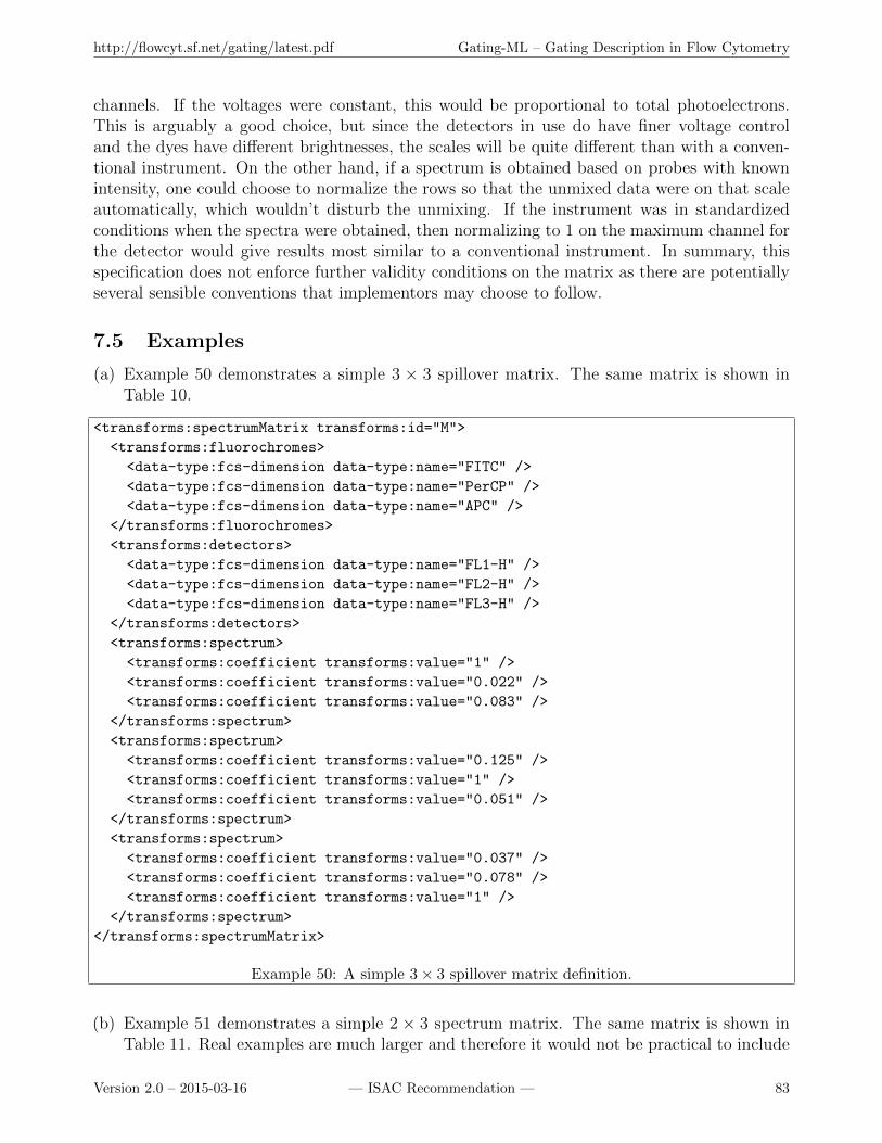
http://flowcyt.sf.net/gating/latest.pdf Gating-ML – Gating Description in Flow Cytometry
channels. If the voltages were constant, this would be proportional to total photoelectrons.This is arguably a good choice, but since the detectors in use do have finer voltage controland the dyes have different brightnesses, the scales will be quite different than with a conven-tional instrument. On the other hand, if a spectrum is obtained based on probes with knownintensity, one could choose to normalize the rows so that the unmixed data were on that scaleautomatically, which wouldn’t disturb the unmixing. If the instrument was in standardizedconditions when the spectra were obtained, then normalizing to 1 on the maximum channel forthe detector would give results most similar to a conventional instrument. In summary, thisspecification does not enforce further validity conditions on the matrix as there are potentiallyseveral sensible conventions that implementors may choose to follow.
7.5 Examples
(a) Example 50 demonstrates a simple 3 × 3 spillover matrix. The same matrix is shown inTable 10.
<transforms:spectrumMatrix transforms:id="M">
<transforms:fluorochromes>
<data-type:fcs-dimension data-type:name="FITC" />
<data-type:fcs-dimension data-type:name="PerCP" />
<data-type:fcs-dimension data-type:name="APC" />
</transforms:fluorochromes>
<transforms:detectors>
<data-type:fcs-dimension data-type:name="FL1-H" />
<data-type:fcs-dimension data-type:name="FL2-H" />
<data-type:fcs-dimension data-type:name="FL3-H" />
</transforms:detectors>
<transforms:spectrum>
<transforms:coefficient transforms:value="1" />
<transforms:coefficient transforms:value="0.022" />
<transforms:coefficient transforms:value="0.083" />
</transforms:spectrum>
<transforms:spectrum>
<transforms:coefficient transforms:value="0.125" />
<transforms:coefficient transforms:value="1" />
<transforms:coefficient transforms:value="0.051" />
</transforms:spectrum>
<transforms:spectrum>
<transforms:coefficient transforms:value="0.037" />
<transforms:coefficient transforms:value="0.078" />
<transforms:coefficient transforms:value="1" />
</transforms:spectrum>
</transforms:spectrumMatrix>
Example 50: A simple 3× 3 spillover matrix definition.
(b) Example 51 demonstrates a simple 2 × 3 spectrum matrix. The same matrix is shown inTable 11. Real examples are much larger and therefore it would not be practical to include
Version 2.0 – 2015-03-16 — ISAC Recommendation — 83
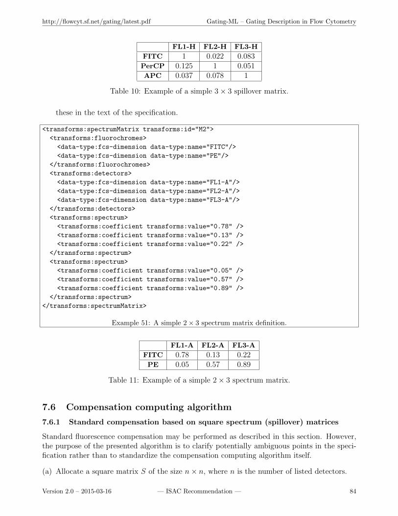
http://flowcyt.sf.net/gating/latest.pdf Gating-ML – Gating Description in Flow Cytometry
FL1-H FL2-H FL3-H
FITC 1 0.022 0.083PerCP 0.125 1 0.051APC 0.037 0.078 1
Table 10: Example of a simple 3× 3 spillover matrix.
these in the text of the specification.
<transforms:spectrumMatrix transforms:id="M2">
<transforms:fluorochromes>
<data-type:fcs-dimension data-type:name="FITC"/>
<data-type:fcs-dimension data-type:name="PE"/>
</transforms:fluorochromes>
<transforms:detectors>
<data-type:fcs-dimension data-type:name="FL1-A"/>
<data-type:fcs-dimension data-type:name="FL2-A"/>
<data-type:fcs-dimension data-type:name="FL3-A"/>
</transforms:detectors>
<transforms:spectrum>
<transforms:coefficient transforms:value="0.78" />
<transforms:coefficient transforms:value="0.13" />
<transforms:coefficient transforms:value="0.22" />
</transforms:spectrum>
<transforms:spectrum>
<transforms:coefficient transforms:value="0.05" />
<transforms:coefficient transforms:value="0.57" />
<transforms:coefficient transforms:value="0.89" />
</transforms:spectrum>
</transforms:spectrumMatrix>
Example 51: A simple 2× 3 spectrum matrix definition.
FL1-A FL2-A FL3-A
FITC 0.78 0.13 0.22PE 0.05 0.57 0.89
Table 11: Example of a simple 2× 3 spectrum matrix.
7.6 Compensation computing algorithm
7.6.1 Standard compensation based on square spectrum (spillover) matrices
Standard fluorescence compensation may be performed as described in this section. However,the purpose of the presented algorithm is to clarify potentially ambiguous points in the speci-fication rather than to standardize the compensation computing algorithm itself.
(a) Allocate a square matrix S of the size n× n, where n is the number of listed detectors.
Version 2.0 – 2015-03-16 — ISAC Recommendation — 84
http://flowcyt.sf.net/gating/latest.pdf Gating-ML – Gating Description in Flow Cytometry
(b) Assign a total ordering on the n detectors so that the order corresponds to detectors orderas listed in the fcs-dimension elements. For i ∈ {1, 2, ..., n}, the i-th detector gets assignedthe i-th row and the i-th column of the matrix S.
(c) Assign values to fields of matrix S by reading and parsing the spectrum and coefficientelements in the row-major order, each spectrum element denoting a new row of the matrix,each coefficient element denoting a value for a field. Formally, assign S[i, j] = V for eachvalue V of the value attribute of the j-th coefficient element that is placed within the i-thspectrum element.
(d) If the value of the matrix-inverted-already attribute is set to false, or the attribute is notpresent in the matrix definition, then compute the matrix S−1 as the inverse of the matrixS. If the value of the matrix-inverted-already attribute is set to true, then the matrix wasinverted already. In that case, you already have the inverse and therefore, simply changethe “label” of S to S−1, which will be used for further calculations.
(e) For each event e in the list more data file:
(i) Read the vector v of expression values of e. Include only values of detectors listed inmatrix S and permute (rearrange) the expression values in v to match the order theyare listed for S. Apply the channel-to-scale transformation on v (see section 3.3.4) asnecessary for event values saved in an FCS file.
(ii) Calculate the vector of compensated values vc of expression values in vector v asvc = v×S−1, i.e., consider v as row vector and multiply v by the inverse of the S; theresult vc will also be a row vector. The vector vc will contain the compensated FCSdimensions in the same order as are the uncompensated dimensions in v. Please notethat there may be negative values resulting from a valid compensation.
7.6.2 Compensation based on non-square spectrum matrices
Even for compensation with non-square spectrum matrices, we assume that the detector mea-surements are a linear combination of the amounts of the various dyes present, and some errorsor noise in the system. Therefore, we seek a linear combination of the measured values that isan estimator of the amount of each dye. We know what detector values to expect (relatively)from each dye from single stained controls. For n dyes (fluorochromes) and m detectors, wehave an n×m spectrum matrix and we seek an n×m unmixing matrix. In order to compensate,we will multiply each m vector of measurement values by the unmixing matrix and get an nvector of dye estimates.
When n = m, there is only one such unmixing matrix for a given spectrum matrix, andthe unmixing process equals to an ordinary compensation. When m > n, the system is overde-termined and there typically isn’t an exact solution. Therefore, we ask for the one that is the“best”, e.g., in the sense of minimizing the squares of residual errors. The optimal solution isfound by some kind of optimization process.
The standard compensation computing algorithm described in Section 7.6.1 can be used forspectral unmixing (compensation based on non-square spectrum matrices) except for computingthe matrix S−1 as the inversion of matrix S. Instead, a Moore–Penrose pseudoinverse [26] S+
of the matrix S would be used. A computationally simple and accurate way to compute
Version 2.0 – 2015-03-16 — ISAC Recommendation — 85
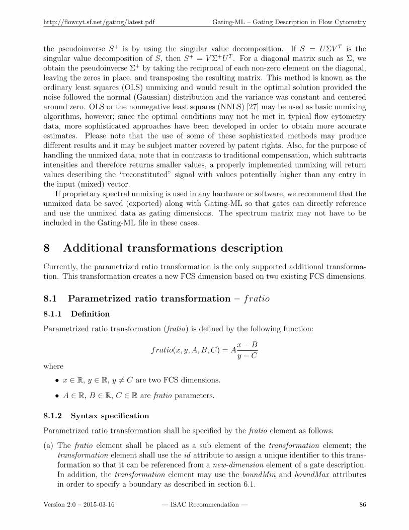
http://flowcyt.sf.net/gating/latest.pdf Gating-ML – Gating Description in Flow Cytometry
the pseudoinverse S+ is by using the singular value decomposition. If S = UΣV T is thesingular value decomposition of S, then S+ = V Σ+UT . For a diagonal matrix such as Σ, weobtain the pseudoinverse Σ+ by taking the reciprocal of each non-zero element on the diagonal,leaving the zeros in place, and transposing the resulting matrix. This method is known as theordinary least squares (OLS) unmixing and would result in the optimal solution provided thenoise followed the normal (Gaussian) distribution and the variance was constant and centeredaround zero. OLS or the nonnegative least squares (NNLS) [27] may be used as basic unmixingalgorithms, however; since the optimal conditions may not be met in typical flow cytometrydata, more sophisticated approaches have been developed in order to obtain more accurateestimates. Please note that the use of some of these sophisticated methods may producedifferent results and it may be subject matter covered by patent rights. Also, for the purpose ofhandling the unmixed data, note that in contrasts to traditional compensation, which subtractsintensities and therefore returns smaller values, a properly implemented unmixing will returnvalues describing the “reconstituted” signal with values potentially higher than any entry inthe input (mixed) vector.
If proprietary spectral unmixing is used in any hardware or software, we recommend that theunmixed data be saved (exported) along with Gating-ML so that gates can directly referenceand use the unmixed data as gating dimensions. The spectrum matrix may not have to beincluded in the Gating-ML file in these cases.
8 Additional transformations description
Currently, the parametrized ratio transformation is the only supported additional transforma-tion. This transformation creates a new FCS dimension based on two existing FCS dimensions.
8.1 Parametrized ratio transformation – fratio
8.1.1 Definition
Parametrized ratio transformation (fratio) is defined by the following function:
fratio(x, y, A,B,C) = Ax−By − C
where
• x ∈ R, y ∈ R, y 6= C are two FCS dimensions.
• A ∈ R, B ∈ R, C ∈ R are fratio parameters.
8.1.2 Syntax specification
Parametrized ratio transformation shall be specified by the fratio element as follows:
(a) The fratio element shall be placed as a sub element of the transformation element; thetransformation element shall use the id attribute to assign a unique identifier to this trans-formation so that it can be referenced from a new-dimension element of a gate description.In addition, the transformation element may use the boundMin and boundMax attributesin order to specify a boundary as described in section 6.1.
Version 2.0 – 2015-03-16 — ISAC Recommendation — 86
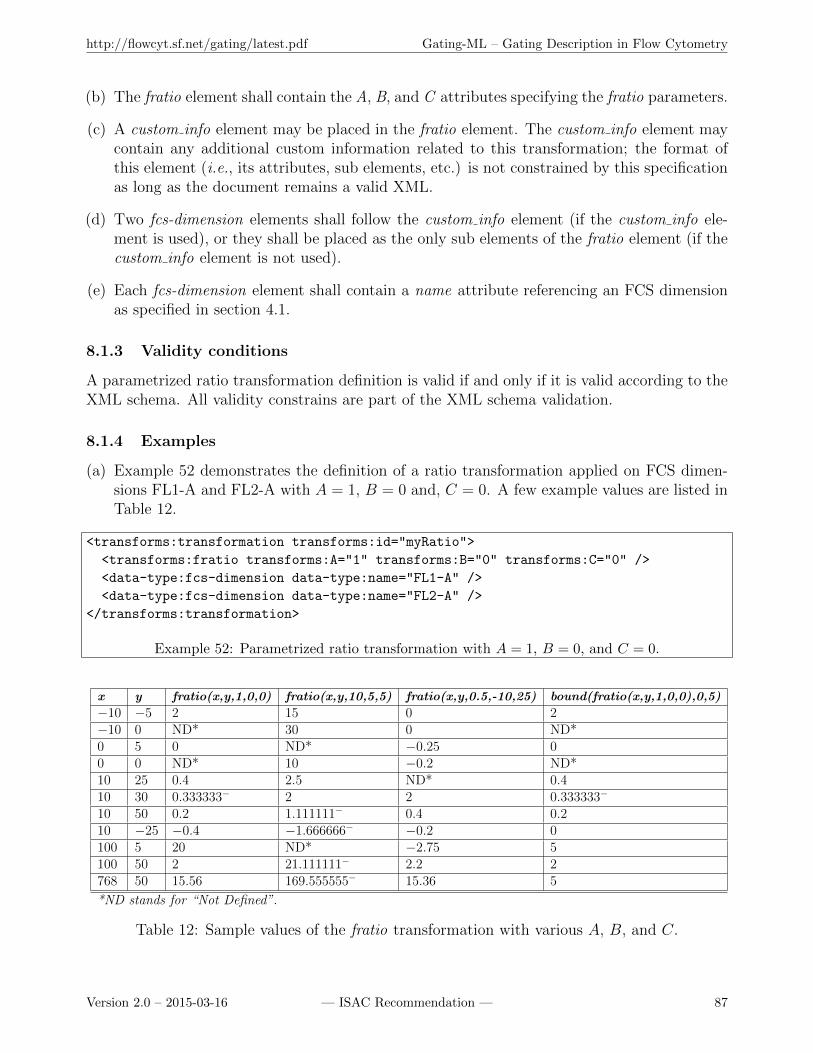
http://flowcyt.sf.net/gating/latest.pdf Gating-ML – Gating Description in Flow Cytometry
(b) The fratio element shall contain the A, B, and C attributes specifying the fratio parameters.
(c) A custom info element may be placed in the fratio element. The custom info element maycontain any additional custom information related to this transformation; the format ofthis element (i.e., its attributes, sub elements, etc.) is not constrained by this specificationas long as the document remains a valid XML.
(d) Two fcs-dimension elements shall follow the custom info element (if the custom info ele-ment is used), or they shall be placed as the only sub elements of the fratio element (if thecustom info element is not used).
(e) Each fcs-dimension element shall contain a name attribute referencing an FCS dimensionas specified in section 4.1.
8.1.3 Validity conditions
A parametrized ratio transformation definition is valid if and only if it is valid according to theXML schema. All validity constrains are part of the XML schema validation.
8.1.4 Examples
(a) Example 52 demonstrates the definition of a ratio transformation applied on FCS dimen-sions FL1-A and FL2-A with A = 1, B = 0 and, C = 0. A few example values are listed inTable 12.
<transforms:transformation transforms:id="myRatio">
<transforms:fratio transforms:A="1" transforms:B="0" transforms:C="0" />
<data-type:fcs-dimension data-type:name="FL1-A" />
<data-type:fcs-dimension data-type:name="FL2-A" />
</transforms:transformation>
Example 52: Parametrized ratio transformation with A = 1, B = 0, and C = 0.
x y fratio(x,y,1,0,0) fratio(x,y,10,5,5) fratio(x,y,0.5,-10,25) bound(fratio(x,y,1,0,0),0,5)
−10 −5 2 15 0 2−10 0 ND* 30 0 ND*0 5 0 ND* −0.25 00 0 ND* 10 −0.2 ND*10 25 0.4 2.5 ND* 0.410 30 0.333333− 2 2 0.333333−
10 50 0.2 1.111111− 0.4 0.210 −25 −0.4 −1.666666− −0.2 0100 5 20 ND* −2.75 5100 50 2 21.111111− 2.2 2768 50 15.56 169.555555− 15.36 5
*ND stands for “Not Defined”.
Table 12: Sample values of the fratio transformation with various A, B, and C.
Version 2.0 – 2015-03-16 — ISAC Recommendation — 87
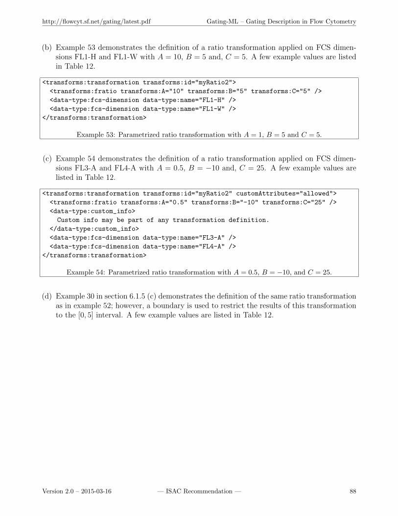
http://flowcyt.sf.net/gating/latest.pdf Gating-ML – Gating Description in Flow Cytometry
(b) Example 53 demonstrates the definition of a ratio transformation applied on FCS dimen-sions FL1-H and FL1-W with A = 10, B = 5 and, C = 5. A few example values are listedin Table 12.
<transforms:transformation transforms:id="myRatio2">
<transforms:fratio transforms:A="10" transforms:B="5" transforms:C="5" />
<data-type:fcs-dimension data-type:name="FL1-H" />
<data-type:fcs-dimension data-type:name="FL1-W" />
</transforms:transformation>
Example 53: Parametrized ratio transformation with A = 1, B = 5 and C = 5.
(c) Example 54 demonstrates the definition of a ratio transformation applied on FCS dimen-sions FL3-A and FL4-A with A = 0.5, B = −10 and, C = 25. A few example values arelisted in Table 12.
<transforms:transformation transforms:id="myRatio2" customAttributes="allowed">
<transforms:fratio transforms:A="0.5" transforms:B="-10" transforms:C="25" />
<data-type:custom_info>
Custom info may be part of any transformation definition.
</data-type:custom_info>
<data-type:fcs-dimension data-type:name="FL3-A" />
<data-type:fcs-dimension data-type:name="FL4-A" />
</transforms:transformation>
Example 54: Parametrized ratio transformation with A = 0.5, B = −10, and C = 25.
(d) Example 30 in section 6.1.5 (c) demonstrates the definition of the same ratio transformationas in example 52; however, a boundary is used to restrict the results of this transformationto the [0, 5] interval. A few example values are listed in Table 12.
Version 2.0 – 2015-03-16 — ISAC Recommendation — 88

http://flowcyt.sf.net/gating/latest.pdf Gating-ML – Gating Description in Flow Cytometry
Version 2.0 – 2015-03-16 — ISAC Recommendation — 89

http://flowcyt.sf.net/gating/latest.pdf Gating-ML – Gating Description in Flow Cytometry
Annex A References
[1] Lee JA, Spidlen J, Boyce K, Cai J, Crosbie N, Dalphin M, Furlong J, Gasparetto M,Goldberg M, Goralczyk EM, Hyun B, Jansen K, Kollmann T, Kong M, Leif R, McWeeneyS, Moloshok TD, Moore W, Nolan G, Nolan J, Nikolich-Zugich J, Parrish D, Purcell B,Qian Y, Selvaraj B, Smith C, Tchuvatkina O, Wertheimer A, Wilkinson P, Wilson C, WoodJ, Zigon R, for Advancement of Cytometry Data Standards Task Force IS, ScheuermannRH, and Brinkman RR. MIFlowCyt: the Minimum Information about a Flow CytometryExperiment. Cytometry Part A, 2008:73(10):926–930.
[2] Spidlen J, Moore W, Parks D, Goldberg M, Bray C, Bierre P, Gorombey P, Hyun B,Hubbard M, Lange S, Lefebvre R, Leif R, Novo D, Ostruszka L, Treister A, Wood J,Murphy RF, Roederer M, Sudar D, Zigon R, and Brinkman RR. Data file standard forflow cytometry, version FCS 3.1. Cytometry A, 2010:77(1):97–100.
[3] World Wide Web Consortium (W3C). Extensible Markup Language (XML) 1.0 (FifthEdition), 2008. http://www.w3.org/TR/2008/REC-xml-20081126/.
[4] World Wide Web Consortium (W3C). W3C Namespaces in XML 1.0 (Third Edition),2009. http://www.w3.org/TR/2009/REC-xml-names-20091208/.
[5] World Wide Web Consortium (W3C). W3C XML Schema Definition Lan-guage (XSD) 1.1 Part 1: Structures, 2012. http://www.w3.org/TR/2012/
REC-xmlschema11-1-20120405/.
[6] World Wide Web Consortium (W3C). W3C XML Schema Definition Language (XSD) 1.1Part 2: Datatypes, 2012. http://www.w3.org/TR/2012/REC-xmlschema11-2-20120405/.
[7] Seamer LC, Bagwell CB, Barden L, Redelman D, Salzman GC, Wood JC, and MurphyRF. Proposed new data file standard for flow cytometry, version FCS 3.0. Cytometry,1997:28(2):118–122.
[8] World Wide Web Consortium (W3C), Math Working Group. W3C Recommendation –Mathematical Markup Language (MathML) Version 2.0 (Second Edition), 2003. http:
//www.w3.org/TR/2003/REC-MathML2-20031021/.
[9] Sun Microsystems, Inc. Java Architecture for XML Binding (JAXB): A Primer. http:
//java.sun.com/developer/technicalArticles/xml/jaxb/.
[10] Bioconductor - Open Source Software for Bioinformatics. http://www.bioconductor.
org/.
[11] World Wide Web Consortium (W3C). W3C Recommendation: Document ObjectModel (DOM) Level 1 Specification, Version 1.0. http://www.w3.org/TR/1998/
REC-DOM-Level-1-19981001/.
[12] Megginson D and Brownell D. SAX: Simple API for XML. http://www.megginson.com/downloads/SAX/.
Version 2.0 – 2015-03-16 — ISAC Recommendation — 90
http://flowcyt.sf.net/gating/latest.pdf Gating-ML – Gating Description in Flow Cytometry
[13] World Wide Web Consortium (W3C). W3C Recommendation - XML Path Language(XPath), Version 1.0. http://www.w3.org/TR/1999/REC-xpath-19991116/.
[14] World Wide Web Consortium (W3C). W3C Recommendation - XSL Transformations(XSLT), Version 1.0. http://www.w3.org/TR/1999/REC-xslt-19991116.
[15] World Wide Web Consortium (W3C). W3C Working Draft - XML Pointer Language(XPointer). http://www.w3.org/TR/2002/WD-xptr-20020816/.
[16] Spidlen J, Leif RC, Moore W, Roederer M, Brinkman RR, and the International Societyfor the Advancement of Cytometry Data Standards Task Force. Gating-ML: XML-basedgating descriptions in flow cytometry. Cytometry A, 2008:73(12):1151–1157.
[17] Unidata. NetCDF – Network Common Data Form. http://www.unidata.ucar.edu/
software/netcdf/.
[18] Shafranovich Y. Common Format and MIME Type for Comma-Separated Values (CSV)File. Internet Society: Request for Comments (4180), 2005:http://tools.ietf.org/html/rfc4180.
[19] O’Rourke J. Computational Geometry in C; Cambridge Tracts in Theoretical ComputerScience. Cambridge University Press, 1998.
[20] Sunday D. Geometry Algorithms - Algorithm 3 - Point in a Polygon.
[21] Chenney S. Drawing Polygons, CS 559-14, Spring 2004.
[22] Moore WA and Parks DR. Update for the logicle data scale including operational codeimplementations. Cytometry A., 2012:81A(4):273–277.
[23] Parks DR, Roederer M, and Moore WA. A new ”Logicle” display method avoids deceptiveeffects of logarithmic scaling for low signals and compensated data. Cytometry A., 2006:69(6):541–551.
[24] Bagwell CB. Hyperlog-a flexible log-like transform for negative, zero, and positive valueddata. Cytometry A., 2005:64(1):34–42.
[25] Roederer M. Spectral compensation for flow cytometry: visualization artifacts, limitations,and caveats. Cytometry, 2001:45(3):194–205.
[26] Lawson CL and Hanson RJ. Generalized Inverses: Theory and Applications, SecondEdition. Springer-Verlag GmbH, 2003.
[27] Ben-Israel A and Greville TN. Solving Least Squares Problems. Prentice-Hall, 1974.
Version 2.0 – 2015-03-16 — ISAC Recommendation — 91
http://flowcyt.sf.net/gating/latest.pdf Gating-ML – Gating Description in Flow Cytometry
Annex B Summary of changes since Gating-ML 1.5
This informative annex provides a brief summary of the major changes to the Gating-MLspecification since Gating-ML version 1.5, i.e., since the ISAC Candidate Recommendationfrom October 30, 2008. A short rationale for these changes is also included.
• Spillover matrices have been replaced with spectrum matrices; these do not have to besquare any no longer and, since there is no longer a direct correspondence between rowsand columns, the spectrum matrices include separate sets of labels for detectors andfluorochromes. In addition, the option of providing the “already inverted” matrix is alsosupported.
• Decision tree gates are no longer be supported. These gates were not very useful andtheir inclusion complicated the implementation of the specification.
• Polytope gates are no longer be supported. These gates were not very useful and theirinclusion complicated the implementation of the specification.
• Boolean gates no longer support the in-line definition of their operand gates. The elimina-tion of this option simplifies the specification while still allowing to describe all cases. Theoperand gates may still be defined outside of the Boolean gate definition and referencedfrom a Boolean gate. In addition, each operand O may be used as either O (default) orNOT(O) (by setting the value of the use-as-complement attribute to true). This allowsfor a simple creation of expressions such as “A AND NOT(B)”.
• Quadrant gates have been included. The inclusion of these gates has been requested byusers of the specification and the community.
• Event values from FCS files are referenced as scale values (see section 3.3.4). Gating-ML 1.5 used to reference channel values and consequently, their conversion to the “scalevalues” had to be explicitly described in Gating-ML (typically the very first transforma-tion), which unnecessarily complicated the workflow description considering that such atransformation is unambiguously defined within the FCS data file standard already.
• The general framework allowing for any kind of compound transformations is no longersupported. Instead, each gating dimension is defined by
(i) One FCS dimension (i.e., values of the $PnN keywords as stored in the FCS datafile or an appropriate alternative for different list mode data file formats) or a newlycreated dimension (ratio is the only supported transformation that creates a newdimension).
(ii) Zero or one explicitly defined compensation description. Technically, each gatingdimension states explicitly whether the event values shall be used uncompensated orcompensated. For compensated values, it is also specified whether the compensationshall be carried out based on a spectrum (spillover) matrix included in the Gating-ML file or according to the description included in the list mode data file (e.g.,the $SPILLOVER keyword in an FCS file). Gates applied on data compensatedaccording to a Gating-ML spectrum matrix reference their dimensions using the
Version 2.0 – 2015-03-16 — ISAC Recommendation — 92
http://flowcyt.sf.net/gating/latest.pdf Gating-ML – Gating Description in Flow Cytometry
names of the rows of the matrix, which may be different from the detector names incase of spectral unmixing.
(iii) Zero or one scale transformation.
This new design aspect still supports all typical work flows while significantly simplifyingthe implementation of the specification.
• Custom and vendor specific information may be included in the Gating-ML file using thecustom info elements and additional custom attributes (see section 4.8). The custom infoelements may be placed at the top level (i.e., as sub elements of the main Gating-MLelement) or as sub elements of the spectrumMatrix elements, transformation elements, orany of the gate definition elements.
• Transformations, such as the polynomial of degree one, the quadratic transformation, thesquare root transformation, the exponential transformation, the hyperbolic sine trans-formation, the “EH” transformation (i.e., inverse to Hyperlog), split scale, and the in-verse split scale transformation are no longer supported with no equivalent replacementincluded. Most of these transformations were originally present since Gating-ML 1.5 in-cluded inverse transformations for all display transformations, which are not needed anymore.
• The Logicle transformation has been added. This addition has been made in responseto the fact that Stanford no longer requires royalties on the Logicle transformation, seehttp://otlportal.stanford.edu/techfinder/technology/ID=23438.
• Optional transformation boundaries have been added to all scale transformations as spec-ified in section 6.1.
• The terminology has been improved, mostly to avoid confusion and conflicts between gen-eral (common) meaning of a term vs. its meaning in flow cytometry or this specification.For example, the term “parameter” is no longer used to reference “FCS dimensions” (seesection 4.1). In addition, most of the transformations have been renamed in order todistinguish between a common and well defined mathematical function and a specificallyparametrized Gating-ML transformation (e.g., asinh vs. fasinh).
• Parameterization of the included transformation has been modified to harmonize howparameters are used across different transformations. In addition, the transformationshave been altered to map the range of expected event values to the [0,1] interval. Thesechanges simplify the comparison of different transformations and suggest a reasonable fallback strategy in case a particular transformation is not implemented. In addition, thesechanges simplify scale visualization due to the explicitly known minimum and maximumvalues (i.e., 0 and 1, respectively, see section 4.7).
• The parametrized ratio transformation has been taken out from the list of “scale” trans-formations and placed into a special group of transformations creating new dimensions;these may be combined with scale transformations and compensation (spectral unmixing).
• The spillover (now spectrum) matrix coefficient values are no longer restricted to the [0, 1]interval. This restriction was wrongly introduced by Gating-ML 1.5.
Version 2.0 – 2015-03-16 — ISAC Recommendation — 93
http://flowcyt.sf.net/gating/latest.pdf Gating-ML – Gating Description in Flow Cytometry
• Reference implementation for the included transformations has been provided in order tofacilitate correct third party implementations.
• MathML documentation for the transformations is no longer provided. MathML descrip-tion of the transformation functions has not been useful to any of the users of the previousversions of the Gating-ML specification.
Annex C ISAC Data Standards Task Force Members
Ryan Brinkman, BC Cancer Agency (chair)
Jay Almarode, FlowJo, LLC
Ernie Anderson, Beckman Coulter Life Sciences
Kim Blenman, Yale University
Chris Bray, Verity Software House
Martin Buscher, Miltenyi Biotechnology
James Cavenaugh
Michael Goldberg, BD Biosciences
Bill Hyun, University of California, San Francisco
David Kripal, Cytek Development Inc.
Kevin Krouse, Labkey, Inc.
Robert Leif, Newport Instruments
Wayne Moore, Stanford University
David Novo, De Novo Software
David Parks, Stanford University
Josef Spidlen, BC Cancer Agency
Adam Treister, Fluourish, Inc.
James Wood, Wake Forest University
Michael Zordan, Sony Biotechnology
Version 2.0 – 2015-03-16 — ISAC Recommendation — 94
Related Documents