ASME Class 150 - 2500, 8mm - 50mm (1/4” - 2”), API 6D API 602 | BS 5352 | BS 6364 | ASME B16.34 | MSS SP 84 Gate, Globe & Check Valves Forged Steel

Welcome message from author
This document is posted to help you gain knowledge. Please leave a comment to let me know what you think about it! Share it to your friends and learn new things together.
Transcript
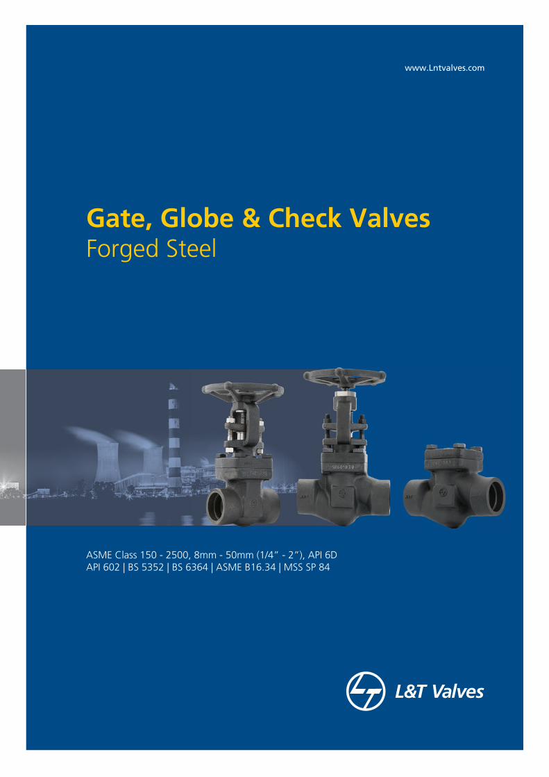
ASME Class 150 - 2500, 8mm - 50mm (1/4” - 2”), API 6DAPI 602 | BS 5352 | BS 6364 | ASME B16.34 | MSS SP 84
Gate, Globe & Check ValvesForged Steel
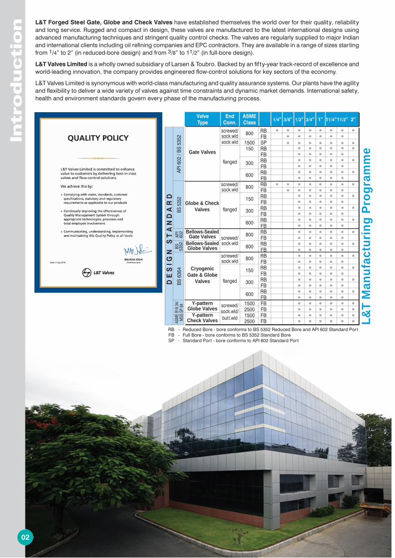
L&T Forged Steel Gate, Globe and Check Valves have established themselves the world over for their quality, reliability and long service. Rugged and compact in design, these valves are manufactured to the latest international designs using advanced manufacturing techniques and stringent quality control checks. The valves are regularly supplied to major Indian and international clients including oil refining companies and EPC contractors. They are available in a range of sizes starting from 1/4” to 2” (in reduced-bore design) and from 3/8” to 11/2” (in full-bore design).
L&T Valves Limited is a wholly owned subsidiary of Larsen & Toubro. Backed by an fif ty-year track-record of excellence and world-leading innovation, the company provides engineered flow-control solutions for key sectors of the economy.
L&T Valves Limited is synonymous with world-class manufacturing and quality assurance systems. Our plants have the agility and flexibility to deliver a wide variety of valves against time constraints and dynamic market demands. International safety, health and environment standards govern every phase of the manufacturing process.
2 11
Intr
oducti
on
02
L&
T Y
-patte
rn V
alv
es
11
ValveClass 1500 Class 2500
Size A B C D E FApp.Wt.
A B C D E FApp.Wt.
(kg) (kg)
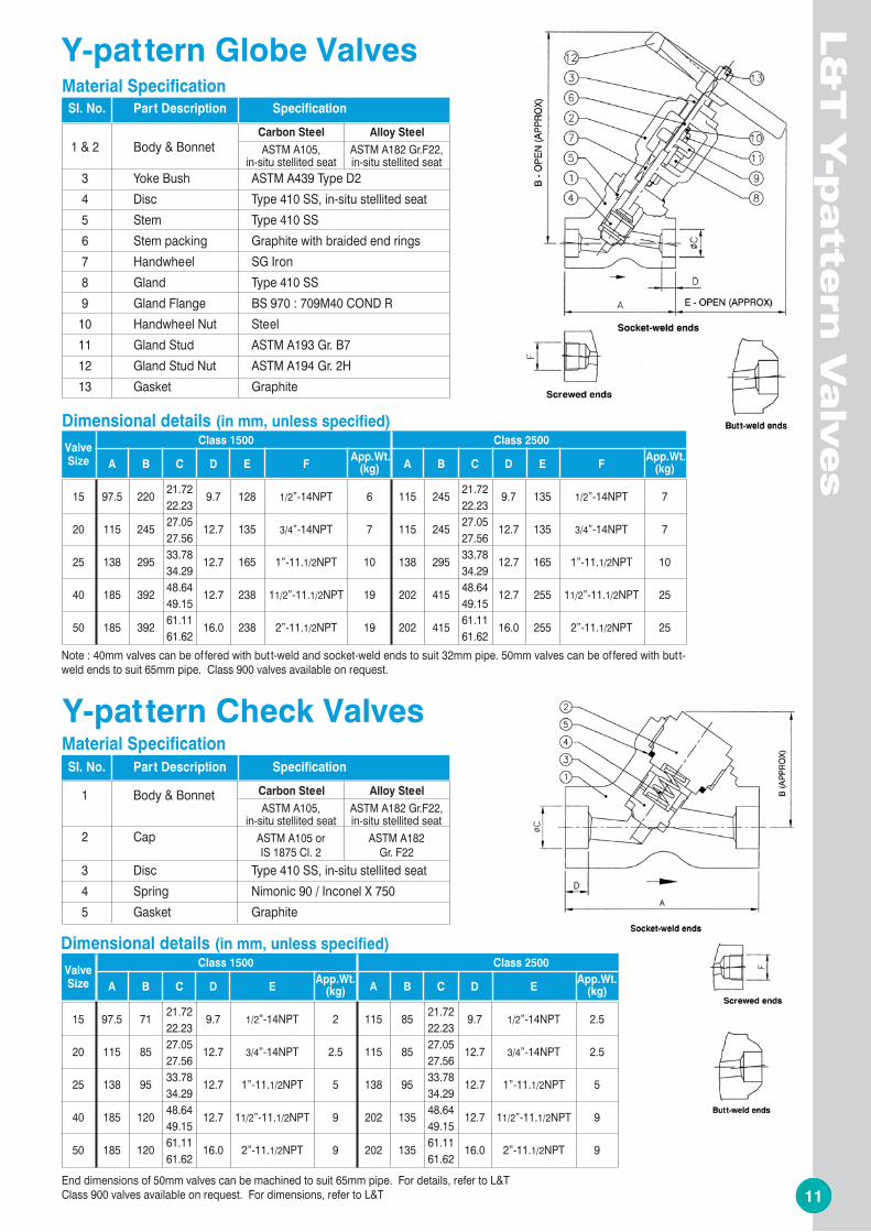
15 97.5 220 21.72 9.7 128 1/2”-14NPT 6 115 245 21.72 9.7 135 1/2”-14NPT 722.23 22.23
20 115 245 27.05 12.7 135 3/4”-14NPT 7 115 245 27.05 12.7 135 3/4”-14NPT 727.56 27.56
25 138 295 33.78 12.7 165 1”-11.1/2NPT 10 138 295 33.78 12.7 165 1”-11.1/2NPT 1034.29 34.29
40 185 392 48.64 12.7 238 11/2”-11.1/2NPT 19 202 415 48.64 12.7 255 11/2”-11.1/2NPT 2549.15 49.15
50 185 392 61.11 16.0 238 2”-11.1/2NPT 19 202 415 61.11 16.0 255 2”-11.1/2NPT 2561.62 61.62
Dimensional details (in mm, unless specified)
ValveClass 1500 Class 2500
Size A B C D EApp.Wt.
A B C D EApp.Wt.
(kg) (kg)
15 97.5 71 21.72 9.7 1/2”-14NPT 2 115 85 21.72 9.7 1/2”-14NPT 2.522.23 22.23
20 115 85 27.05 12.7 3/4”-14NPT 2.5 115 85 27.05 12.7 3/4”-14NPT 2.527.56 27.56
25 138 95 33.78 12.7 1”-11.1/2NPT 5 138 95 33.78 12.7 1”-11.1/2NPT 534.29 34.29
40 185 120 48.64 12.7 11/2”-11.1/2NPT 9 202 135 48.64 12.7 11/2”-11.1/2NPT 949.15 49.15
50 185 120 61.11 16.0 2”-11.1/2NPT 9 202 135 61.11 16.0 2”-11.1/2NPT 961.62 61.62
Dimensional details (in mm, unless specified)
Note : 40mm valves can be of fered with butt-weld and socket-weld ends to suit 32mm pipe. 50mm valves can be of fered with butt-weld ends to suit 65mm pipe. Class 900 valves available on request.
Sl. No. Part Description Specification
1 Body & Bonnet Carbon Steel Alloy Steel
2 Cap
3 Disc Type 410 SS, in-situ stellited seat 4 Spring Nimonic 90 / Inconel X 7505 Gasket Graphite
Material Specification
ASTM A105 orIS 1875 Cl. 2
ASTM A182Gr. F22
ASTM A182 Gr.F22,in-situ stellited seat
ASTM A105,in-situ stellited seat
End dimensions of 50mm valves can be machined to suit 65mm pipe. For details, refer to L&TClass 900 valves available on request. For dimensions, refer to L&T
Y-pattern Globe Valves
Sl. No. Part Description Specification
1 & 2 Body & BonnetCarbon Steel Alloy Steel
3 Yoke Bush ASTM A439 Type D24 Disc Type 410 SS, in-situ stellited seat 5 Stem Type 410 SS6 Stem packing Graphite with braided end rings7 Handwheel SG Iron8 Gland Type 410 SS9 Gland Flange BS 970 : 709M40 COND R
10 Handwheel Nut Steel11 Gland Stud ASTM A193 Gr. B712 Gland Stud Nut ASTM A194 Gr. 2H13 Gasket Graphite
Material Specification
ASTM A182 Gr.F22,in-situ stellited seat
ASTM A105,in-situ stellited seat
Y-pattern Check ValvesL&T
Man
ufac
turi
ng P
rogr
amm
e
DE
SIG
N S
TA
ND
AR
DAP
I 602
/ BS
535
2BS
5352
ASME
B16.3
4/MS
S SP 8
4
Valve End ASME 1/4” 3/8” 1/2” 3/4” 1” 11/4” 11/2” 2”Type Conn. Class
screwed/ 800 RB
sock.wld FB
sock.wld 1500 SP
150 RB
FB
flanged 300 RB
FB 600 RB
FB
screwed/ 800 RB
sock.wld FB
150 RB
FB
flanged 300 RB
FB 600 RB
FB
800 RB
screwed/ FB
sock.wld 800 RB
FB
screwed/ 800 RB
sock.wld FB
150 RB
FB
flanged 300 RB
FB
600 RB
FB
screwed/ 1500 FB
sock.wld/ 2500 FB
but t.wld 1500 FB
2500 FB
CryogenicGate & Globe
Valves
Globe & CheckValves
Y-patternGlobe Valves
BS 6
364
Y-patternCheck Valves
Gate Valves
Bellows-SealedGate Valves
RB - Reduced Bore - bore conforms to BS 5352 Reduced Bore and API 602 Standard PortFB - Full Bore - bore conforms to BS 5352 Standard BoreSP - Standard Port - bore conforms to API 602 Standard Port
Bellows-SealedGlobe Valves
API
602
BS 5352
10 3
Technic
al In
form
atio
n
03
L&
T Y
-patt
ern
Valv
es
10
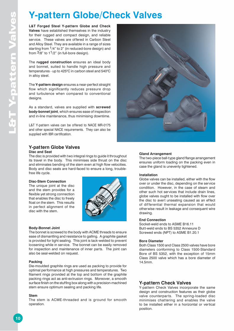
L&T Forged Steel Y-pat tern Globe and Check Valves have established themselves in the industry for their rugged and compact design, and reliable service. These valves are of fered in Carbon Steel and Alloy Steel. They are available in a range of sizes starting from 1/4” to 2” (in reduced-bore design) and from 3/8” to 11/2” (in full-bore design).
The rugged construction ensures an ideal body and bonnet, suited to handle high pressure and temperatures - up to 4250C in carbon steel and 5400C in alloy steel.
The Y-pattern design ensures a near-perfect straight flow which significantly reduces pressure drop and turbulence when compared to conventional designs.
As a standard, valves are supplied with screwed body-bonnet joint, which ensures ease of inspection and in-line maintenance, thus minimising downtime.
L&T Y-pat tern valves can be of fered to NACE MR-0175 and other special NACE requirements. They can also be supplied with IBR certification.
Familiarity with our catalogue numbering is not necessary when specifying or ordering our valves. A full description of the valve provided by you is translated into a catalogue number as per the system shown.
For any other special requirement, add SPL to the catalogue number and provide details.
Y-pattern Globe/Check Valves
Y-pattern Globe ValvesDisc and SeatThe disc is provided with two integral rings to guide it throughout its travel in the body. This minimises side thrust on the disc and eliminates bending of the stem even at high flow velocities. Body and disc seats are hard-faced to ensure a long, trouble-free life cycle.
Disc-Stem ConnectionThe unique joint at the disc and the stem provides for a flexible yet strong connection that enables the disc to freely float on the stem. This results in per fect alignment of the disc with the stem.
Body-Bonnet JointThe bonnet is screwed to the body with ACME threads to ensure ease of dismantling and resistance to galling. A graphite gasket is provided for tight sealing. This joint is tack-welded to prevent loosening while in service. The bonnet can be easily removed for inspection and maintenance of inner parts. The joint can also be seal-welded on request.
PackingDie-moulded graphite rings are used as packing to provide for optimal performance at high pressures and temperatures. Two filament rings provided at the top and bottom of the graphite packing rings act as anti-extrusion rings. Moreover, a smooth surface finish on the stuf fing box along with a precision-machined stem ensure optimum sealing and packing life.
StemThe stem is ACME-threaded and is ground for smooth operation.
Gland ArrangementThe two-piece ball-type gland flange arrangement ensures uniform loading on the packing even in case the gland is unevenly tightened.
InstallationGlobe valves can be installed, either with the flow over or under the disc, depending on the service condition. However, in the case of steam and other such hot services that include drain lines, globe valves ought to be installed with flow over the disc to avert unseating caused as an ef fect of dif ferential thermal expansion that would otherwise result in leakage and consequent wire drawing.
End ConnectionSocket-weld ends to ASME B16.11Butt-weld ends to BS 5352 Annexure DScrewed ends (NPT) to ASME B1.20.1
Bore DiameterBoth Class 1500 and Class 2500 valves have bore diameters conforming to Class 1500-Standard Bore of BS 5352, with the exception of 15mm Class 2500 valve which has a bore diameter of 14.5mm.
Y-pattern Check ValvesY-pat tern Check Valves incorporate the same design and construction features as their globe valve counterpar ts. The spring-loaded disc minimises chat tering and enables the valve to be installed either in a horizontal or ver tical position.
Size Valve type Pressure Class End Connection Trim Body material
15 - 15mm 20 - 20mm 25 - 25mm 40 - 40mm 50 - 50mm
6 - Scr. Bonnet 7 - Seal-welded Bonnet
GLOBE 15 - Class 1500 25 - Class 2500
3 - Butt-weld 4 - Screwed NPT 5 - Socket-weld
U - Hardfaced seating surface
NIL - A105 F11 F22
8 - Scr. Cap 9 - Seal-welded Cap
F316 F316L F347
NIL - Standard IBR - IBR-certified
Options
CHECK
Ordering Information - Y-pattern Valves
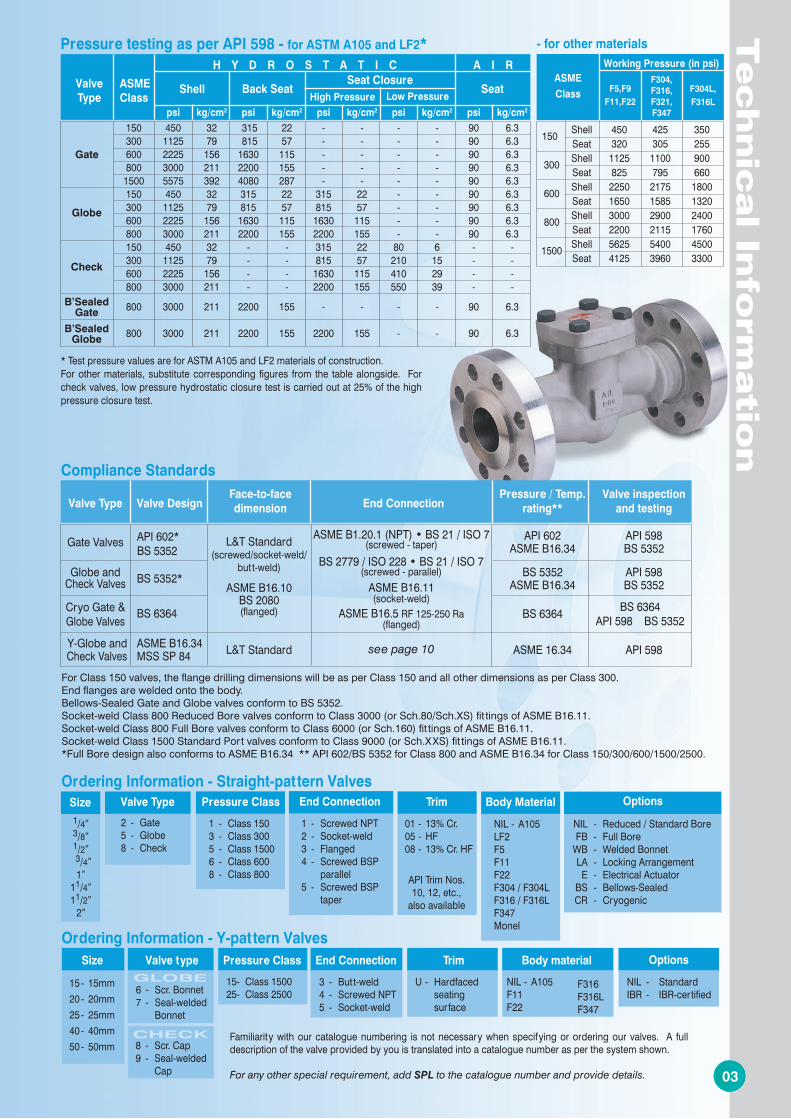
Compliance Standards
BS 6364API 598 BS 5352
Valve Type Valve Design
Face-to-face End Connection
Pressure / Temp. Valve inspection dimension rating** and testing
Gate Valves API 602 API 598 ASME B16.34 BS 5352 Globe and BS 5352 API 598 Check Valves BS 5352* ASME B16.34 BS 5352 Cryo Gate & BS 6364 Globe Valves
BS 6364
Y-Globe and ASME B16.34 ASME 16.34 API 598 Check Valves MSS SP 84
L&T Standard(screwed/socket-weld/
butt-weld)
ASME B16.10BS 2080(flanged)
ASME B1.20.1 (NPT) • BS 21 / ISO 7(screwed - taper)
ASME B16.5 RF 125-250 Ra(flanged)
L&T Standard
ASME B16.11(socket-weld)
BS 2779 / ISO 228 • BS 21 / ISO 7(screwed - parallel)
API 602*BS 5352
For Class 150 valves, the flange drilling dimensions will be as per Class 150 and all other dimensions as per Class 300.End flanges are welded onto the body.Bellows-Sealed Gate and Globe valves conform to BS 5352.Socket-weld Class 800 Reduced Bore valves conform to Class 3000 (or Sch.80/Sch.XS) fit tings of ASME B16.11.Socket-weld Class 800 Full Bore valves conform to Class 6000 (or Sch.160) fit tings of ASME B16.11.Socket-weld Class 1500 Standard Port valves conform to Class 9000 (or Sch.XXS) fit tings of ASME B16.11.*Full Bore design also conforms to ASME B16.34 ** API 602/BS 5352 for Class 800 and ASME B16.34 for Class 150/300/600/1500/2500.
see page 10
Valve
TypeASMEClass
H Y D R O S T A T I C A I R
Shell Back SeatSeat Closure
High Pressure Low PressureSeat
psi kg/cm2 psi kg/cm2 psi kg/cm2 psi kg/cm2 psi kg/cm2
150 450 32 315 22 - - - - 90 6.3 300 1125 79 815 57 - - - - 90 6.3 600 2225 156 1630 115 - - - - 90 6.3 800 3000 211 2200 155 - - - - 90 6.3 1500 5575 392 4080 287 - - - - 90 6.3 150 450 32 315 22 315 22 - - 90 6.3 300 1125 79 815 57 815 57 - - 90 6.3 600 2225 156 1630 115 1630 115 - - 90 6.3 800 3000 211 2200 155 2200 155 - - 90 6.3 150 450 32 - - 315 22 80 6 - - 300 1125 79 - - 815 57 210 15 - - 600 2225 156 - - 1630 115 410 29 - - 800 3000 211 - - 2200 155 550 39 - - 800 3000 211 2200 155 - - - - 90 6.3 800 3000 211 2200 155 2200 155 - - 90 6.3
Gate
Globe
Check
B’SealedGate
B’SealedGlobe
Pressure testing as per API 598 - for ASTM A105 and LF2*
* Test pressure values are for ASTM A105 and LF2 materials of construction.For other materials, substitute corresponding figures from the table alongside. For check valves, low pressure hydrostatic closure test is carried out at 25% of the high pressure closure test.
Working Pressure (in psi)
150 Shell 450 425 350 Seat 320 305 255 300 Shell 1125 1100 900 Seat 825 795 660 600 Shell 2250 2175 1800 Seat 1650 1585 1320 800 Shell 3000 2900 2400 Seat 2200 2115 1760 1500 Shell 5625 5400 4500 Seat 4125 3960 3300
ASME
Class F5,F9F11,F22
F304,F316,F321,F347
F304L,F316L
- for other materials
Ordering Information - Straight-pattern ValvesTrim
NIL - A105 LF2 F5 F11 F22 F304 / F304L F316 / F316L F347 Monel
Body Material
NIL - Reduced / Standard Bore FB - Full Bore WB - Welded Bonnet LA - Locking Arrangement E - Electrical Actuator BS - Bellows-Sealed CR - Cryogenic
Options
1 - Screwed NPT 2 - Socket-weld 3 - Flanged 4 - Screwed BSP parallel 5 - Screwed BSP taper
End Connection
1 - Class 150 3 - Class 300 5 - Class 1500 6 - Class 600 8 - Class 800
Pressure Class
2 - Gate 5 - Globe 8 - Check
Valve Type1/4”3/8”1/2”
3/4”1”
11/4”11/2”
2”
Size
01 - 13% Cr. 05 - HF 08 - 13% Cr. HF
API Trim Nos.10, 12, etc.,
also available
4 9
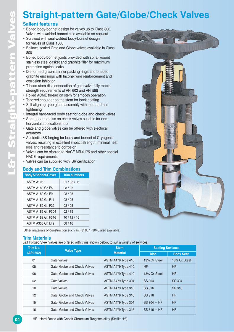
Salient features •Boltedbody-bonnetdesignforvalvesuptoClass800.
Valves with welded bonnet also available on request•Screwedwithseal-weldedbody-bonnetdesign for valves of Class 1500•Bellows-sealedGateandGlobevalvesavailableinClass
800•Boltedbody-bonnetjointsprovidedwithspiral-wound
stainless steel gasket and graphite filler for maximum protection against leaks
•Die-formedgraphiteinnerpackingringsandbraidedgraphite end rings with Inconel wire reinforcement and corrosion inhibitor
•T-headstem-discconnectionofgatevalvefullymeetsstrength requirements of API 602 and API 598
•RolledACMEthreadonstemforsmoothoperation•Taperedshoulderonthestemforbackseating•Self-aligningtypeglandassemblywithstud-and-nut
tightening•Integralhard-facedbodyseatforglobeandcheckvalves•Spring-loadeddisconcheckvalvessuitablefornon-
horizontal applications too•Gateandglobevalvescanbeof feredwithelectrical
actuators•AusteniticSSforgingforbodyandbonnetofCryogenic
valves, resulting in excellent impact strength, minimal heat loss and resistance to corrosion
•Valvescanbeof feredtoNACEMR-0175andotherspecialNACE requirements
•ValvescanbesuppliedwithIBRcertification
L&
T S
traig
ht-
patt
ern
Valv
es
04
L&
T S
traig
ht-p
atte
rn V
alv
es
09
Other materials of construction such as F316L / F304L also available.
Body & Bonnet/Cover Trim numbers
ASTM A105 01 / 08 / 05 ASTM A182 Gr. F5 08 / 05 ASTM A182 Gr. F9 08 / 05 ASTM A182 Gr. F11 08 / 05 ASTM A182 Gr. F22 08 / 05 ASTM A182 Gr. F304 02 / 15 ASTM A182 Gr. F316 10 / 12 / 16 ASTM A350 Gr. LF2 08 / 16
Body and Trim Combinations
Trim Materials
Trim No. Valve Type
Stem Seating Surfaces (API 602) Material Disc Body Seat
01 Gate Valves ASTM A479 Type 410 13% Cr. Steel 13% Cr. Steel 05 Gate, Globe and Check Valves ASTM A479 Type 410 HF HF
08 Gate, Globe and Check Valves ASTM A479 Type 410 13% Cr. Steel HF
02 Gate Valves ASTM A479 Type 304 SS 304 SS 304
10 Gate Valves ASTM A479 Type 316 SS 316 SS 316
12 Gate, Globe and Check Valves ASTM A479 Type 316 SS 316 HF
15 Gate, Globe and Check Valves ASTM A479 Type 304 SS 304 + HF HF
16 Gate, Globe and Check Valves ASTM A479 Type 316 SS 316 + HF HF
HF - Hard Faced with Cobalt-Chromium-Tungsten alloy (Stellite #6)
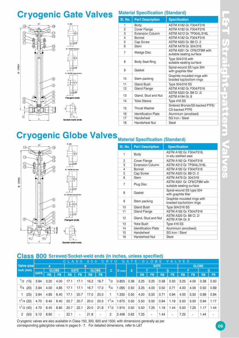
Cryogenic Gate Valves
Cryogenic Globe Valves
Sl. No. Part Description Specification
1 Body ASTM A182 Gr. F304/F316 2 Cover Flange ASTM A182 Gr. F304/F316 3 Extension Column ASTM A312 Gr. TP304L/316L 4 Bonnet ASTM A182 Gr. F304/F316 5 Cap Screw ASTM A320 Gr. B8 Cl. 2 6 Stem ASTM A479 Gr. 304/316 7 Wedge Disc ASTM A351 Gr. CF8/CF8M with suitable seating surface
8 Body Seat Ring Type 304/316 with
suitable seating surface
9 Gasket Spiral-wound SS type 304
with graphite filler
10 Stem packing Graphite moulded rings with
braided top/bottom rings 11 Gland Bush Type 304/316 SS 12 Gland Flange ASTM A182 Gr. F304/F316
13 Gland, Stud and Nut ASTM A320 Gr. B8 Cl. 2/
ASTM A194 Gr. 8 14 Yoke Sleeve Type 416 SS
15 Thrust Washer Sintered Bronze/SS-backed PTFE/
CS-backed PTFE 16 Identification Plate Aluminium (anodised) 17 Handwheel SG Iron / Steel 18 Handwheel Nut Steel
Material Specification (Standard)
Sl. No. Part Description Specification
1 Body ASTM A182 Gr. F304/F316, in-situ stellited seat 2 Cover Flange ASTM A182 Gr. F304/F316 3 Extension Column ASTM A312 Gr. TP304L/316L 4 Bonnet ASTM A182 Gr. F304/F316 5 Cap Screw ASTM A320 Gr. B8 Cl. 2 6 Stem ASTM A479 Gr. 304/316 7 Plug Disc ASTM A351 Gr. CF8/CF8M with suitable seating surface 8 Gasket Spiral-wound SS type 304 with graphite filler 9 Stem packing Graphite moulded rings with braided top/bottom rings 10 Gland Bush Type 304/316 SS 11 Gland Flange ASTM A182 Gr. F304/F316 12 Gland, Stud and Nut ASTM A320 Gr. B8 Cl. 2/ ASTM A194 Gr. 8 13 Yoke Bush Type 416 SS 14 Identification Plate Aluminium (anodised) 15 Handwheel SG Iron / Steel 16 Handwheel Nut Steel
Material Specification (Standard)
Screwed/Socket-weld ends (in inches, unless specified)C L A S S 8 0 0 C R Y O G A T E / G L O B E V A L V E S
RB FBGATE GLOBE
GATEGLOBE
Class 800
RB FBRB FBRB FB
GATE GLOBE
RB FB RB FB RB FB
Cryogenic valves are also available in Class 150, 300, 600 and 1500, with dimensions generally as per corresponding gate/globe valves in pages 5 - 7. For detailed dimensions, refer to L&T
Straight-pattern Gate/Globe/Check Valves
L&T Forged Steel Valves are of fered with trims shown below, to suit a variety of services.
Valve size
inch (mm)
A
B
C D (min) E
F G F G
1/2 (15) 3.94 3.20 4.00 17.1 17.1 16.2 16.7 1/2 0.855 0.38 3.25 3.25 0.38 0.50 3.25 4.00 0.38 0.50 3/4 (20) 3.94 4.00 4.85 17.1 17.1 16.7 17.0 3/4 1.065 0.50 3.25 4.00 0.50 0.71 4.00 4.00 0.50 0.69
1 (25) 3.94 4.85 6.40 17.1 20.7 17.0 20.0 1 1.330 0.50 4.00 5.50 0.71 0.94 4.00 5.50 0.69 0.94
11/4 (32) 4.70 6.40 6.40 20.7 20.7 20.0 20.0 11/4 1.675 0.50 5.50 5.50 0.94 1.19 5.50 5.50 0.94 1.17
11/2 (40) 4.70 6.40 8.80 20.7 22.1 20.0 21.8 11/2 1.915 0.50 5.50 7.25 1.19 1.44 5.50 7.25 1.17 1.44
2 (50) 5.12 8.80 - 22.1 - 21.8 - 2 2.406 0.62 7.25 - 1.44 - 7.25 - 1.44 -
8 5
0508
RB FB RB FB
Flanged ends (in inches, unless specified)C L A S S 6 0 0 G A T E V A L V E S
RB FBRB FB
RB FB
Flanged ends (in inches, unless specified)
Class 150 Class 300
C L A S S 1 5 0 / 3 0 0 G A T E V A L V E S
RB FB
Screwed/Socket-weld ends (in inches, unless specified)
RB FB RB FB RB FB RB FB
C L A S S 8 0 0 C H E C K V A L V E S
RB FB
Flanged ends (in inches, unless specified)
Class 150 Class 300
C L A S S 1 5 0 / 3 0 0 C H E C K V A L V E S
Screwed/Socket-weld ends (in inches, unless specified)
RB FB RB FB RB FBRB FB RB FB
C L A S S 8 0 0 G A T E V A L V E S
L&
T S
traig
ht-
patt
ern
Valv
es
L&
T S
traig
ht-p
atte
rn V
alv
es
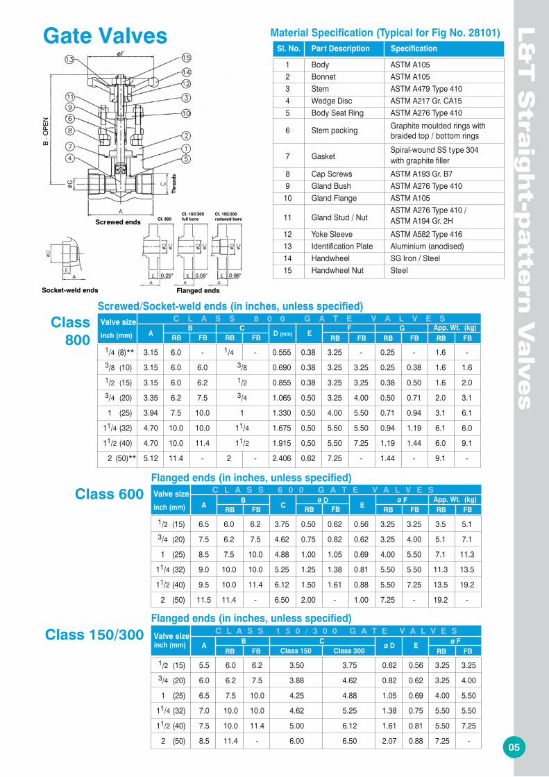
Gate Valves
Class800
Class 600
Class 150/300
Class800
Class150/300
Check Valves
Flanged ends (in inches, unless specified)
RB FB RB FBRB FB
C L A S S 6 0 0 C H E C K V A L V E S Class 600RB FB
RB FB
Sl. No. Part Description Specification
1 Body ASTM A105, in-situ stellited seat 2 Cover ASTM A105 3 Piston Disc ASTM A276 Type 410 4 Spring SS 302
5 Gasket Spiral-wound SS type 304
with graphite filler 6 Cap Screws ASTM A193 Gr. B7 7 Identification Plate Aluminium (anodised)
Material Specification (Typical for Fig No. 88108)Sl. No. Part Description Specification
1 Body ASTM A105 2 Bonnet ASTM A105 3 Stem ASTM A479 Type 410 4 Wedge Disc ASTM A217 Gr. CA15 5 Body Seat Ring ASTM A276 Type 410 6 Stem packing Graphite moulded rings with braided top / bottom rings
7 Gasket Spiral-wound SS type 304
with graphite filler 8 Cap Screws ASTM A193 Gr. B7 9 Gland Bush ASTM A276 Type 410 10 Gland Flange ASTM A105
11 Gland Stud / Nut ASTM A276 Type 410 /
ASTM A194 Gr. 2H 12 Yoke Sleeve ASTM A582 Type 416 13 Identification Plate Aluminium (anodised) 14 Handwheel SG Iron / Steel 15 Handwheel Nut Steel
Material Specification (Typical for Fig No. 28101)
* Greater thanASME B16.10 / BS 2080
* Greater thanASME B16.10 / BS 2080
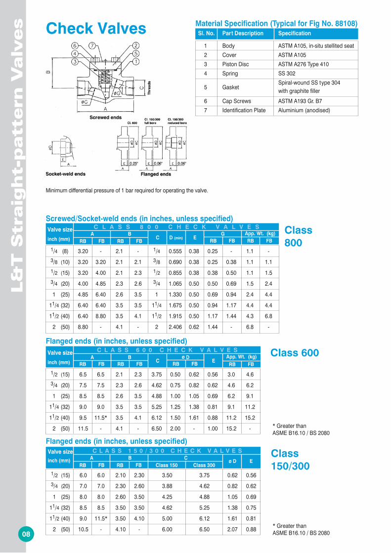
Minimum differential pressure of 1 bar required for operating the valve.
Valve size
inch (mm) A
B
C ø D
E App. Wt. (kg)
1/2 (15) 6.5 6.5 2.1 2.3 3.75 0.50 0.62 0.56 3.0 4.6 3/4 (20) 7.5 7.5 2.3 2.6 4.62 0.75 0.82 0.62 4.6 6.2
1 (25) 8.5 8.5 2.6 3.5 4.88 1.00 1.05 0.69 6.2 9.1
11/4 (32) 9.0 9.0 3.5 3.5 5.25 1.25 1.38 0.81 9.1 11.2
11/2 (40) 9.5 11.5* 3.5 4.1 6.12 1.50 1.61 0.88 11.2 15.2
2 (50) 11.5 - 4.1 - 6.50 2.00 - 1.00 15.2 -
Valve size inch (mm)
A
B
C ø D E
1/2 (15) 6.0 6.0 2.10 2.30 3.50 3.75 0.62 0.56
3/4 (20) 7.0 7.0 2.30 2.60 3.88 4.62 0.82 0.62 1 (25) 8.0 8.0 2.60 3.50 4.25 4.88 1.05 0.69
11/4 (32) 8.5 8.5 3.50 3.50 4.62 5.25 1.38 0.75
11/2 (40) 9.0 11.5* 3.50 4.10 5.00 6.12 1.61 0.81
2 (50) 10.5 - 4.10 - 6.00 6.50 2.07 0.88
Valve size
inch (mm) A
B
C D (min) E G App. Wt. (kg)
1/4 (8) 3.20 - 2.1 - 1/4 0.555 0.38 0.25 - 1.1 - 3/8 (10) 3.20 3.20 2.1 2.1 3/8 0.690 0.38 0.25 0.38 1.1 1.1
1/2 (15) 3.20 4.00 2.1 2.3 1/2 0.855 0.38 0.38 0.50 1.1 1.5 3/4 (20) 4.00 4.85 2.3 2.6 3/4 1.065 0.50 0.50 0.69 1.5 2.4
1 (25) 4.85 6.40 2.6 3.5 1 1.330 0.50 0.69 0.94 2.4 4.4
11/4 (32) 6.40 6.40 3.5 3.5 11/4 1.675 0.50 0.94 1.17 4.4 4.4
11/2 (40) 6.40 8.80 3.5 4.1 11/2 1.915 0.50 1.17 1.44 4.3 6.8
2 (50) 8.80 - 4.1 - 2 2.406 0.62 1.44 - 6.8 -
Valve size
inch (mm) A B
C
D (min) E F G
App. Wt. (kg)
1/4 (8)** 3.15 6.0 - 1/4 - 0.555 0.38 3.25 - 0.25 - 1.6 - 3/8 (10) 3.15 6.0 6.0 3/8 0.690 0.38 3.25 3.25 0.25 0.38 1.6 1.6
1/2 (15) 3.15 6.0 6.2 1/2 0.855 0.38 3.25 3.25 0.38 0.50 1.6 2.0 3/4 (20) 3.35 6.2 7.5 3/4 1.065 0.50 3.25 4.00 0.50 0.71 2.0 3.1
1 (25) 3.94 7.5 10.0 1 1.330 0.50 4.00 5.50 0.71 0.94 3.1 6.1
11/4 (32) 4.70 10.0 10.0 11/4 1.675 0.50 5.50 5.50 0.94 1.19 6.1 6.0
11/2 (40) 4.70 10.0 11.4 11/2 1.915 0.50 5.50 7.25 1.19 1.44 6.0 9.1
2 (50)** 5.12 11.4 - 2 - 2.406 0.62 7.25 - 1.44 - 9.1 -
Valve size
inch (mm) A B
C ø D
E ø F
App. Wt. (kg)
1/2 (15) 6.5 6.0 6.2 3.75 0.50 0.62 0.56 3.25 3.25 3.5 5.1 3/4 (20) 7.5 6.2 7.5 4.62 0.75 0.82 0.62 3.25 4.00 5.1 7.1
1 (25) 8.5 7.5 10.0 4.88 1.00 1.05 0.69 4.00 5.50 7.1 11.3
11/4 (32) 9.0 10.0 10.0 5.25 1.25 1.38 0.81 5.50 5.50 11.3 13.5
11/2 (40) 9.5 10.0 11.4 6.12 1.50 1.61 0.88 5.50 7.25 13.5 19.2
2 (50) 11.5 11.4 - 6.50 2.00 - 1.00 7.25 - 19.2 -
Valve size inch (mm) A
B
C ø D E
ø F 1/2 (15) 5.5 6.0 6.2 3.50 3.75 0.62 0.56 3.25 3.25
3/4 (20) 6.0 6.2 7.5 3.88 4.62 0.82 0.62 3.25 4.00 1 (25) 6.5 7.5 10.0 4.25 4.88 1.05 0.69 4.00 5.50
11/4 (32) 7.0 10.0 10.0 4.62 5.25 1.38 0.75 5.50 5.50
11/2 (40) 7.5 10.0 11.4 5.00 6.12 1.61 0.81 5.50 7.25
2 (50) 8.5 11.4 - 6.00 6.50 2.07 0.88 7.25 -
6 7
0706
Screwed/Socket-weld ends (in inches, unless specified)
RB FB RB FB RB FBRB FB RB FB
C L A S S 8 0 0 G L O B E V A L V E S
L&
T S
traig
ht-
patt
ern
Valv
es
L&
T S
traig
ht-p
atte
rn V
alv
es
Class800
Globe ValvesGate Valves
RB FB RB FB
Flanged ends (in inches, unless specified)
RB FBRB FB
C L A S S 6 0 0 G L O B E V A L V E SClass 600RB FB
RB FB
Flanged ends (in inches, unless specified)
Class 150 Class 300
C L A S S 1 5 0 / 3 0 0 G L O B E V A L V E S
RB FB
Class150/300 RB FB
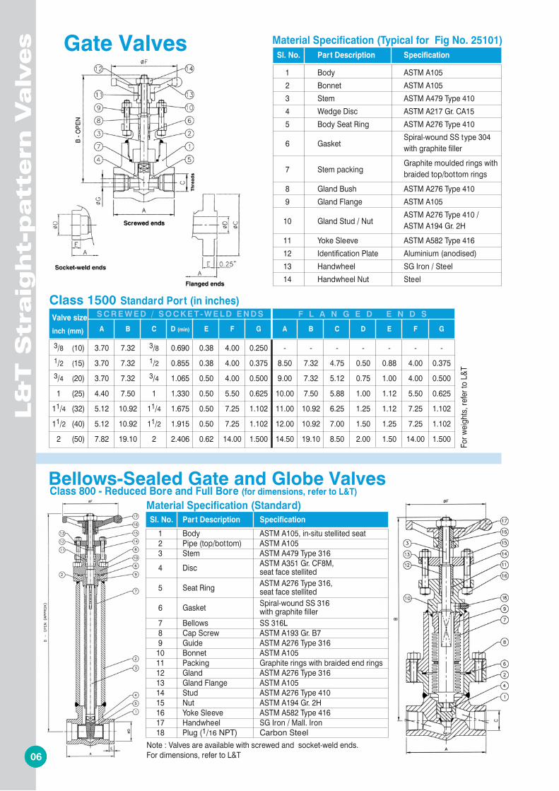
Class 1500 Standard Port (in inches) Valve size
inch (mm) A B C D (min) E F G A B C D E F G
3/8 (10) 3.70 7.32 3/8 0.690 0.38 4.00 0.250 - - - - - - -
1/2 (15) 3.70 7.32 1/2 0.855 0.38 4.00 0.375 8.50 7.32 4.75 0.50 0.88 4.00 0.375 3/4 (20) 3.70 7.32 3/4 1.065 0.50 4.00 0.500 9.00 7.32 5.12 0.75 1.00 4.00 0.500
1 (25) 4.40 7.50 1 1.330 0.50 5.50 0.625 10.00 7.50 5.88 1.00 1.12 5.50 0.625
11/4 (32) 5.12 10.92 11/4 1.675 0.50 7.25 1.102 11.00 10.92 6.25 1.25 1.12 7.25 1.102
11/2 (40) 5.12 10.92 11/2 1.915 0.50 7.25 1.102 12.00 10.92 7.00 1.50 1.25 7.25 1.102
2 (50) 7.82 19.10 2 2.406 0.62 14.00 1.500 14.50 19.10 8.50 2.00 1.50 14.00 1.500
S C R E W E D / S O C K E T - W E L D E N D S
For w
eight
s, re
fer t
o L&
T
F L A N G E D E N D S
Bellows-Sealed Gate and Globe ValvesClass 800 - Reduced Bore and Full Bore (for dimensions, refer to L&T)
Sl. No. Part Description Specification
1 Body ASTM A105 2 Bonnet ASTM A105 3 Stem ASTM A479 Type 410 4 Wedge Disc ASTM A217 Gr. CA15 5 Body Seat Ring ASTM A276 Type 410
6 Gasket Spiral-wound SS type 304
with graphite filler
7 Stem packing Graphite moulded rings with
braided top/bottom rings 8 Gland Bush ASTM A276 Type 410 9 Gland Flange ASTM A105
10 Gland Stud / Nut ASTM A276 Type 410 /
ASTM A194 Gr. 2H 11 Yoke Sleeve ASTM A582 Type 416 12 Identification Plate Aluminium (anodised) 13 Handwheel SG Iron / Steel 14 Handwheel Nut Steel
Material Specification (Typical for Fig No. 25101)Sl. No. Part Description Specification
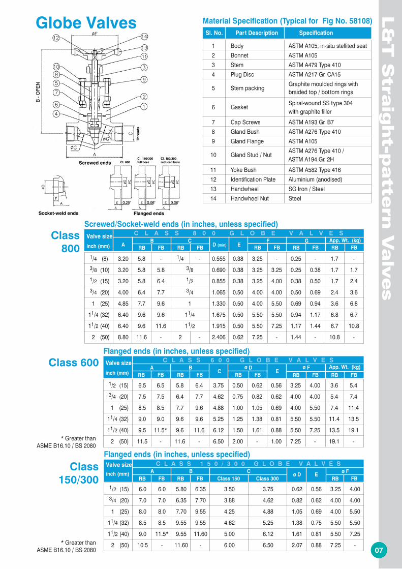
1 Body ASTM A105, in-situ stellited seat 2 Bonnet ASTM A105 3 Stem ASTM A479 Type 410 4 Plug Disc ASTM A217 Gr. CA15 5 Stem packing Graphite moulded rings with braided top / bottom rings
6 Gasket Spiral-wound SS type 304 with graphite filler 7 Cap Screws ASTM A193 Gr. B7 8 Gland Bush ASTM A276 Type 410 9 Gland Flange ASTM A105 10 Gland Stud / Nut ASTM A276 Type 410 / ASTM A194 Gr. 2H 11 Yoke Bush ASTM A582 Type 416 12 Identification Plate Aluminium (anodised) 13 Handwheel SG Iron / Steel 14 Handwheel Nut Steel
Material Specification (Typical for Fig No. 58108)
* Greater thanASME B16.10 / BS 2080
* Greater thanASME B16.10 / BS 2080
Sl. No. Part Description Specification
1 Body ASTM A105, in-situ stellited seat 2 Pipe (top/bottom) ASTM A105 3 Stem ASTM A479 Type 316 4 Disc ASTM A351 Gr. CF8M, seat face stellited 5 Seat Ring ASTM A276 Type 316, seat face stellited 6 Gasket Spiral-wound SS 316 with graphite filler 7 Bellows SS 316L 8 Cap Screw ASTM A193 Gr. B7 9 Guide ASTM A276 Type 316 10 Bonnet ASTM A105 11 Packing Graphite rings with braided end rings 12 Gland ASTM A276 Type 316 13 Gland Flange ASTM A105 14 Stud ASTM A276 Type 410 15 Nut ASTM A194 Gr. 2H 16 Yoke Sleeve ASTM A582 Type 416 17 Handwheel SG Iron / Mall. Iron 18 Plug (1/16 NPT) Carbon Steel
Material Specification (Standard)
Note : Valves are available with screwed and socket-weld ends.For dimensions, refer to L&T
Valve size
inch (mm) A B
C
D (min) E F G
App. Wt. (kg)
1/4 (8) 3.20 5.8 - 1/4 - 0.555 0.38 3.25 - 0.25 - 1.7 - 3/8 (10) 3.20 5.8 5.8 3/8 0.690 0.38 3.25 3.25 0.25 0.38 1.7 1.7
1/2 (15) 3.20 5.8 6.4 1/2 0.855 0.38 3.25 4.00 0.38 0.50 1.7 2.4 3/4 (20) 4.00 6.4 7.7 3/4 1.065 0.50 4.00 4.00 0.50 0.69 2.4 3.6
1 (25) 4.85 7.7 9.6 1 1.330 0.50 4.00 5.50 0.69 0.94 3.6 6.8
11/4 (32) 6.40 9.6 9.6 11/4 1.675 0.50 5.50 5.50 0.94 1.17 6.8 6.7
11/2 (40) 6.40 9.6 11.6 11/2 1.915 0.50 5.50 7.25 1.17 1.44 6.7 10.8
2 (50) 8.80 11.6 - 2 - 2.406 0.62 7.25 - 1.44 - 10.8 -
Valve size
inch (mm) A
B
C ø D
E ø F
App. Wt. (kg)
1/2 (15) 6.5 6.5 5.8 6.4 3.75 0.50 0.62 0.56 3.25 4.00 3.6 5.4
3/4 (20) 7.5 7.5 6.4 7.7 4.62 0.75 0.82 0.62 4.00 4.00 5.4 7.4
1 (25) 8.5 8.5 7.7 9.6 4.88 1.00 1.05 0.69 4.00 5.50 7.4 11.4
11/4 (32) 9.0 9.0 9.6 9.6 5.25 1.25 1.38 0.81 5.50 5.50 11.4 13.5
11/2 (40) 9.5 11.5* 9.6 11.6 6.12 1.50 1.61 0.88 5.50 7.25 13.5 19.1
2 (50) 11.5 - 11.6 - 6.50 2.00 - 1.00 7.25 - 19.1 -
Valve size inch (mm)
A
B
C ø D E
ø F
1/2 (15) 6.0 6.0 5.80 6.35 3.50 3.75 0.62 0.56 3.25 4.00
3/4 (20) 7.0 7.0 6.35 7.70 3.88 4.62 0.82 0.62 4.00 4.00 1 (25) 8.0 8.0 7.70 9.55 4.25 4.88 1.05 0.69 4.00 5.50
11/4 (32) 8.5 8.5 9.55 9.55 4.62 5.25 1.38 0.75 5.50 5.50
11/2 (40) 9.0 11.5* 9.55 11.60 5.00 6.12 1.61 0.81 5.50 7.25
2 (50) 10.5 - 11.60 - 6.00 6.50 2.07 0.88 7.25 -
6 7
0706
Screwed/Socket-weld ends (in inches, unless specified)
RB FB RB FB RB FBRB FB RB FB
C L A S S 8 0 0 G L O B E V A L V E S
L&
T S
traig
ht-
patt
ern
Valv
es
L&
T S
traig
ht-p
atte
rn V
alv
es
Class800
Globe ValvesGate Valves
RB FB RB FB
Flanged ends (in inches, unless specified)
RB FBRB FB
C L A S S 6 0 0 G L O B E V A L V E SClass 600RB FB
RB FB
Flanged ends (in inches, unless specified)
Class 150 Class 300
C L A S S 1 5 0 / 3 0 0 G L O B E V A L V E S
RB FB
Class150/300 RB FB
Class 1500 Standard Port (in inches) Valve size
inch (mm) A B C D (min) E F G A B C D E F G
3/8 (10) 3.70 7.32 3/8 0.690 0.38 4.00 0.250 - - - - - - -
1/2 (15) 3.70 7.32 1/2 0.855 0.38 4.00 0.375 8.50 7.32 4.75 0.50 0.88 4.00 0.375 3/4 (20) 3.70 7.32 3/4 1.065 0.50 4.00 0.500 9.00 7.32 5.12 0.75 1.00 4.00 0.500
1 (25) 4.40 7.50 1 1.330 0.50 5.50 0.625 10.00 7.50 5.88 1.00 1.12 5.50 0.625
11/4 (32) 5.12 10.92 11/4 1.675 0.50 7.25 1.102 11.00 10.92 6.25 1.25 1.12 7.25 1.102
11/2 (40) 5.12 10.92 11/2 1.915 0.50 7.25 1.102 12.00 10.92 7.00 1.50 1.25 7.25 1.102
2 (50) 7.82 19.10 2 2.406 0.62 14.00 1.500 14.50 19.10 8.50 2.00 1.50 14.00 1.500
S C R E W E D / S O C K E T - W E L D E N D S
For w
eight
s, re
fer t
o L&
T
F L A N G E D E N D S
Bellows-Sealed Gate and Globe ValvesClass 800 - Reduced Bore and Full Bore (for dimensions, refer to L&T)
Sl. No. Part Description Specification
1 Body ASTM A105 2 Bonnet ASTM A105 3 Stem ASTM A479 Type 410 4 Wedge Disc ASTM A217 Gr. CA15 5 Body Seat Ring ASTM A276 Type 410
6 Gasket Spiral-wound SS type 304
with graphite filler
7 Stem packing Graphite moulded rings with
braided top/bottom rings 8 Gland Bush ASTM A276 Type 410 9 Gland Flange ASTM A105
10 Gland Stud / Nut ASTM A276 Type 410 /
ASTM A194 Gr. 2H 11 Yoke Sleeve ASTM A582 Type 416 12 Identification Plate Aluminium (anodised) 13 Handwheel SG Iron / Steel 14 Handwheel Nut Steel
Material Specification (Typical for Fig No. 25101)Sl. No. Part Description Specification
1 Body ASTM A105, in-situ stellited seat 2 Bonnet ASTM A105 3 Stem ASTM A479 Type 410 4 Plug Disc ASTM A217 Gr. CA15 5 Stem packing Graphite moulded rings with braided top / bottom rings
6 Gasket Spiral-wound SS type 304 with graphite filler 7 Cap Screws ASTM A193 Gr. B7 8 Gland Bush ASTM A276 Type 410 9 Gland Flange ASTM A105 10 Gland Stud / Nut ASTM A276 Type 410 / ASTM A194 Gr. 2H 11 Yoke Bush ASTM A582 Type 416 12 Identification Plate Aluminium (anodised) 13 Handwheel SG Iron / Steel 14 Handwheel Nut Steel
Material Specification (Typical for Fig No. 58108)
* Greater thanASME B16.10 / BS 2080
* Greater thanASME B16.10 / BS 2080
Sl. No. Part Description Specification
1 Body ASTM A105, in-situ stellited seat 2 Pipe (top/bottom) ASTM A105 3 Stem ASTM A479 Type 316 4 Disc ASTM A351 Gr. CF8M, seat face stellited 5 Seat Ring ASTM A276 Type 316, seat face stellited 6 Gasket Spiral-wound SS 316 with graphite filler 7 Bellows SS 316L 8 Cap Screw ASTM A193 Gr. B7 9 Guide ASTM A276 Type 316 10 Bonnet ASTM A105 11 Packing Graphite rings with braided end rings 12 Gland ASTM A276 Type 316 13 Gland Flange ASTM A105 14 Stud ASTM A276 Type 410 15 Nut ASTM A194 Gr. 2H 16 Yoke Sleeve ASTM A582 Type 416 17 Handwheel SG Iron / Mall. Iron 18 Plug (1/16 NPT) Carbon Steel
Material Specification (Standard)
Note : Valves are available with screwed and socket-weld ends.For dimensions, refer to L&T
Valve size
inch (mm) A B
C
D (min) E F G
App. Wt. (kg)
1/4 (8) 3.20 5.8 - 1/4 - 0.555 0.38 3.25 - 0.25 - 1.7 - 3/8 (10) 3.20 5.8 5.8 3/8 0.690 0.38 3.25 3.25 0.25 0.38 1.7 1.7
1/2 (15) 3.20 5.8 6.4 1/2 0.855 0.38 3.25 4.00 0.38 0.50 1.7 2.4 3/4 (20) 4.00 6.4 7.7 3/4 1.065 0.50 4.00 4.00 0.50 0.69 2.4 3.6
1 (25) 4.85 7.7 9.6 1 1.330 0.50 4.00 5.50 0.69 0.94 3.6 6.8
11/4 (32) 6.40 9.6 9.6 11/4 1.675 0.50 5.50 5.50 0.94 1.17 6.8 6.7
11/2 (40) 6.40 9.6 11.6 11/2 1.915 0.50 5.50 7.25 1.17 1.44 6.7 10.8
2 (50) 8.80 11.6 - 2 - 2.406 0.62 7.25 - 1.44 - 10.8 -
Valve size
inch (mm) A
B
C ø D
E ø F
App. Wt. (kg)
1/2 (15) 6.5 6.5 5.8 6.4 3.75 0.50 0.62 0.56 3.25 4.00 3.6 5.4
3/4 (20) 7.5 7.5 6.4 7.7 4.62 0.75 0.82 0.62 4.00 4.00 5.4 7.4
1 (25) 8.5 8.5 7.7 9.6 4.88 1.00 1.05 0.69 4.00 5.50 7.4 11.4
11/4 (32) 9.0 9.0 9.6 9.6 5.25 1.25 1.38 0.81 5.50 5.50 11.4 13.5
11/2 (40) 9.5 11.5* 9.6 11.6 6.12 1.50 1.61 0.88 5.50 7.25 13.5 19.1
2 (50) 11.5 - 11.6 - 6.50 2.00 - 1.00 7.25 - 19.1 -
Valve size inch (mm)
A
B
C ø D E
ø F
1/2 (15) 6.0 6.0 5.80 6.35 3.50 3.75 0.62 0.56 3.25 4.00
3/4 (20) 7.0 7.0 6.35 7.70 3.88 4.62 0.82 0.62 4.00 4.00 1 (25) 8.0 8.0 7.70 9.55 4.25 4.88 1.05 0.69 4.00 5.50
11/4 (32) 8.5 8.5 9.55 9.55 4.62 5.25 1.38 0.75 5.50 5.50
11/2 (40) 9.0 11.5* 9.55 11.60 5.00 6.12 1.61 0.81 5.50 7.25
2 (50) 10.5 - 11.60 - 6.00 6.50 2.07 0.88 7.25 -
8 5
0508
RB FB RB FB
Flanged ends (in inches, unless specified)C L A S S 6 0 0 G A T E V A L V E S
RB FBRB FB
RB FB
Flanged ends (in inches, unless specified)
Class 150 Class 300
C L A S S 1 5 0 / 3 0 0 G A T E V A L V E S
RB FB
Screwed/Socket-weld ends (in inches, unless specified)
RB FB RB FB RB FB RB FB
C L A S S 8 0 0 C H E C K V A L V E S
RB FB
Flanged ends (in inches, unless specified)
Class 150 Class 300
C L A S S 1 5 0 / 3 0 0 C H E C K V A L V E S
Screwed/Socket-weld ends (in inches, unless specified)
RB FB RB FB RB FBRB FB RB FB
C L A S S 8 0 0 G A T E V A L V E S
L&
T S
traig
ht-
patt
ern
Valv
es
L&
T S
traig
ht-p
atte
rn V
alv
es
Gate Valves
Class800
Class 600
Class 150/300
Class800
Class150/300
Check Valves
Flanged ends (in inches, unless specified)
RB FB RB FBRB FB
C L A S S 6 0 0 C H E C K V A L V E S Class 600RB FB
RB FB
Sl. No. Part Description Specification
1 Body ASTM A105, in-situ stellited seat 2 Cover ASTM A105 3 Piston Disc ASTM A276 Type 410 4 Spring SS 302
5 Gasket Spiral-wound SS type 304
with graphite filler 6 Cap Screws ASTM A193 Gr. B7 7 Identification Plate Aluminium (anodised)
Material Specification (Typical for Fig No. 88108)Sl. No. Part Description Specification
1 Body ASTM A105 2 Bonnet ASTM A105 3 Stem ASTM A479 Type 410 4 Wedge Disc ASTM A217 Gr. CA15 5 Body Seat Ring ASTM A276 Type 410 6 Stem packing Graphite moulded rings with braided top / bottom rings
7 Gasket Spiral-wound SS type 304
with graphite filler 8 Cap Screws ASTM A193 Gr. B7 9 Gland Bush ASTM A276 Type 410 10 Gland Flange ASTM A105
11 Gland Stud / Nut ASTM A276 Type 410 /
ASTM A194 Gr. 2H 12 Yoke Sleeve ASTM A582 Type 416 13 Identification Plate Aluminium (anodised) 14 Handwheel SG Iron / Steel 15 Handwheel Nut Steel
Material Specification (Typical for Fig No. 28101)
* Greater thanASME B16.10 / BS 2080
* Greater thanASME B16.10 / BS 2080
Minimum differential pressure of 1 bar required for operating the valve.
Valve size
inch (mm) A
B
C ø D
E App. Wt. (kg)
1/2 (15) 6.5 6.5 2.1 2.3 3.75 0.50 0.62 0.56 3.0 4.6 3/4 (20) 7.5 7.5 2.3 2.6 4.62 0.75 0.82 0.62 4.6 6.2
1 (25) 8.5 8.5 2.6 3.5 4.88 1.00 1.05 0.69 6.2 9.1
11/4 (32) 9.0 9.0 3.5 3.5 5.25 1.25 1.38 0.81 9.1 11.2
11/2 (40) 9.5 11.5* 3.5 4.1 6.12 1.50 1.61 0.88 11.2 15.2
2 (50) 11.5 - 4.1 - 6.50 2.00 - 1.00 15.2 -
Valve size inch (mm)
A
B
C ø D E
1/2 (15) 6.0 6.0 2.10 2.30 3.50 3.75 0.62 0.56
3/4 (20) 7.0 7.0 2.30 2.60 3.88 4.62 0.82 0.62 1 (25) 8.0 8.0 2.60 3.50 4.25 4.88 1.05 0.69
11/4 (32) 8.5 8.5 3.50 3.50 4.62 5.25 1.38 0.75
11/2 (40) 9.0 11.5* 3.50 4.10 5.00 6.12 1.61 0.81
2 (50) 10.5 - 4.10 - 6.00 6.50 2.07 0.88
Valve size
inch (mm) A
B
C D (min) E G App. Wt. (kg)
1/4 (8) 3.20 - 2.1 - 1/4 0.555 0.38 0.25 - 1.1 - 3/8 (10) 3.20 3.20 2.1 2.1 3/8 0.690 0.38 0.25 0.38 1.1 1.1
1/2 (15) 3.20 4.00 2.1 2.3 1/2 0.855 0.38 0.38 0.50 1.1 1.5 3/4 (20) 4.00 4.85 2.3 2.6 3/4 1.065 0.50 0.50 0.69 1.5 2.4
1 (25) 4.85 6.40 2.6 3.5 1 1.330 0.50 0.69 0.94 2.4 4.4
11/4 (32) 6.40 6.40 3.5 3.5 11/4 1.675 0.50 0.94 1.17 4.4 4.4
11/2 (40) 6.40 8.80 3.5 4.1 11/2 1.915 0.50 1.17 1.44 4.3 6.8
2 (50) 8.80 - 4.1 - 2 2.406 0.62 1.44 - 6.8 -
Valve size
inch (mm) A B
C
D (min) E F G
App. Wt. (kg)
1/4 (8)** 3.15 6.0 - 1/4 - 0.555 0.38 3.25 - 0.25 - 1.6 - 3/8 (10) 3.15 6.0 6.0 3/8 0.690 0.38 3.25 3.25 0.25 0.38 1.6 1.6
1/2 (15) 3.15 6.0 6.2 1/2 0.855 0.38 3.25 3.25 0.38 0.50 1.6 2.0 3/4 (20) 3.35 6.2 7.5 3/4 1.065 0.50 3.25 4.00 0.50 0.71 2.0 3.1
1 (25) 3.94 7.5 10.0 1 1.330 0.50 4.00 5.50 0.71 0.94 3.1 6.1
11/4 (32) 4.70 10.0 10.0 11/4 1.675 0.50 5.50 5.50 0.94 1.19 6.1 6.0
11/2 (40) 4.70 10.0 11.4 11/2 1.915 0.50 5.50 7.25 1.19 1.44 6.0 9.1
2 (50)** 5.12 11.4 - 2 - 2.406 0.62 7.25 - 1.44 - 9.1 -
Valve size
inch (mm) A B
C ø D
E ø F
App. Wt. (kg)
1/2 (15) 6.5 6.0 6.2 3.75 0.50 0.62 0.56 3.25 3.25 3.5 5.1 3/4 (20) 7.5 6.2 7.5 4.62 0.75 0.82 0.62 3.25 4.00 5.1 7.1
1 (25) 8.5 7.5 10.0 4.88 1.00 1.05 0.69 4.00 5.50 7.1 11.3
11/4 (32) 9.0 10.0 10.0 5.25 1.25 1.38 0.81 5.50 5.50 11.3 13.5
11/2 (40) 9.5 10.0 11.4 6.12 1.50 1.61 0.88 5.50 7.25 13.5 19.2
2 (50) 11.5 11.4 - 6.50 2.00 - 1.00 7.25 - 19.2 -
Valve size inch (mm) A
B
C ø D E
ø F 1/2 (15) 5.5 6.0 6.2 3.50 3.75 0.62 0.56 3.25 3.25
3/4 (20) 6.0 6.2 7.5 3.88 4.62 0.82 0.62 3.25 4.00 1 (25) 6.5 7.5 10.0 4.25 4.88 1.05 0.69 4.00 5.50
11/4 (32) 7.0 10.0 10.0 4.62 5.25 1.38 0.75 5.50 5.50
11/2 (40) 7.5 10.0 11.4 5.00 6.12 1.61 0.81 5.50 7.25
2 (50) 8.5 11.4 - 6.00 6.50 2.07 0.88 7.25 -
4 9
Salient features •Boltedbody-bonnetdesignforvalvesuptoClass800.
Valves with welded bonnet also available on request•Screwedwithseal-weldedbody-bonnetdesign for valves of Class 1500•Bellows-sealedGateandGlobevalvesavailableinClass
800•Boltedbody-bonnetjointsprovidedwithspiral-wound
stainless steel gasket and graphite filler for maximum protection against leaks
•Die-formedgraphiteinnerpackingringsandbraidedgraphite end rings with Inconel wire reinforcement and corrosion inhibitor
•T-headstem-discconnectionofgatevalvefullymeetsstrength requirements of API 602 and API 598
•RolledACMEthreadonstemforsmoothoperation•Taperedshoulderonthestemforbackseating•Self-aligningtypeglandassemblywithstud-and-nut
tightening•Integralhard-facedbodyseatforglobeandcheckvalves•Spring-loadeddisconcheckvalvessuitablefornon-
horizontal applications too•Gateandglobevalvescanbeof feredwithelectrical
actuators•AusteniticSSforgingforbodyandbonnetofCryogenic
valves, resulting in excellent impact strength, minimal heat loss and resistance to corrosion
•Valvescanbeof feredtoNACEMR-0175andotherspecialNACE requirements
•ValvescanbesuppliedwithIBRcertification
L&
T S
traig
ht-
patt
ern
Valv
es
04
L&
T S
traig
ht-p
atte
rn V
alv
es
09
Other materials of construction such as F316L / F304L also available.
Body & Bonnet/Cover Trim numbers
ASTM A105 01 / 08 / 05 ASTM A182 Gr. F5 08 / 05 ASTM A182 Gr. F9 08 / 05 ASTM A182 Gr. F11 08 / 05 ASTM A182 Gr. F22 08 / 05 ASTM A182 Gr. F304 02 / 15 ASTM A182 Gr. F316 10 / 12 / 16 ASTM A350 Gr. LF2 08 / 16
Body and Trim Combinations
Trim Materials
Trim No. Valve Type
Stem Seating Surfaces (API 602) Material Disc Body Seat
01 Gate Valves ASTM A479 Type 410 13% Cr. Steel 13% Cr. Steel 05 Gate, Globe and Check Valves ASTM A479 Type 410 HF HF
08 Gate, Globe and Check Valves ASTM A479 Type 410 13% Cr. Steel HF
02 Gate Valves ASTM A479 Type 304 SS 304 SS 304
10 Gate Valves ASTM A479 Type 316 SS 316 SS 316
12 Gate, Globe and Check Valves ASTM A479 Type 316 SS 316 HF
15 Gate, Globe and Check Valves ASTM A479 Type 304 SS 304 + HF HF
16 Gate, Globe and Check Valves ASTM A479 Type 316 SS 316 + HF HF
HF - Hard Faced with Cobalt-Chromium-Tungsten alloy (Stellite #6)
Cryogenic Gate Valves
Cryogenic Globe Valves
Sl. No. Part Description Specification
1 Body ASTM A182 Gr. F304/F316 2 Cover Flange ASTM A182 Gr. F304/F316 3 Extension Column ASTM A312 Gr. TP304L/316L 4 Bonnet ASTM A182 Gr. F304/F316 5 Cap Screw ASTM A320 Gr. B8 Cl. 2 6 Stem ASTM A479 Gr. 304/316 7 Wedge Disc ASTM A351 Gr. CF8/CF8M with suitable seating surface
8 Body Seat Ring Type 304/316 with
suitable seating surface
9 Gasket Spiral-wound SS type 304
with graphite filler
10 Stem packing Graphite moulded rings with
braided top/bottom rings 11 Gland Bush Type 304/316 SS 12 Gland Flange ASTM A182 Gr. F304/F316
13 Gland, Stud and Nut ASTM A320 Gr. B8 Cl. 2/
ASTM A194 Gr. 8 14 Yoke Sleeve Type 416 SS
15 Thrust Washer Sintered Bronze/SS-backed PTFE/
CS-backed PTFE 16 Identification Plate Aluminium (anodised) 17 Handwheel SG Iron / Steel 18 Handwheel Nut Steel
Material Specification (Standard)
Sl. No. Part Description Specification
1 Body ASTM A182 Gr. F304/F316, in-situ stellited seat 2 Cover Flange ASTM A182 Gr. F304/F316 3 Extension Column ASTM A312 Gr. TP304L/316L 4 Bonnet ASTM A182 Gr. F304/F316 5 Cap Screw ASTM A320 Gr. B8 Cl. 2 6 Stem ASTM A479 Gr. 304/316 7 Plug Disc ASTM A351 Gr. CF8/CF8M with suitable seating surface 8 Gasket Spiral-wound SS type 304 with graphite filler 9 Stem packing Graphite moulded rings with braided top/bottom rings 10 Gland Bush Type 304/316 SS 11 Gland Flange ASTM A182 Gr. F304/F316 12 Gland, Stud and Nut ASTM A320 Gr. B8 Cl. 2/ ASTM A194 Gr. 8 13 Yoke Bush Type 416 SS 14 Identification Plate Aluminium (anodised) 15 Handwheel SG Iron / Steel 16 Handwheel Nut Steel
Material Specification (Standard)
Screwed/Socket-weld ends (in inches, unless specified)C L A S S 8 0 0 C R Y O G A T E / G L O B E V A L V E S
RB FBGATE GLOBE
GATEGLOBE
Class 800
RB FBRB FBRB FB
GATE GLOBE
RB FB RB FB RB FB
Cryogenic valves are also available in Class 150, 300, 600 and 1500, with dimensions generally as per corresponding gate/globe valves in pages 5 - 7. For detailed dimensions, refer to L&T
Straight-pattern Gate/Globe/Check Valves
L&T Forged Steel Valves are of fered with trims shown below, to suit a variety of services.
Valve size
inch (mm)
A
B
C D (min) E
F G F G
1/2 (15) 3.94 3.20 4.00 17.1 17.1 16.2 16.7 1/2 0.855 0.38 3.25 3.25 0.38 0.50 3.25 4.00 0.38 0.50 3/4 (20) 3.94 4.00 4.85 17.1 17.1 16.7 17.0 3/4 1.065 0.50 3.25 4.00 0.50 0.71 4.00 4.00 0.50 0.69
1 (25) 3.94 4.85 6.40 17.1 20.7 17.0 20.0 1 1.330 0.50 4.00 5.50 0.71 0.94 4.00 5.50 0.69 0.94
11/4 (32) 4.70 6.40 6.40 20.7 20.7 20.0 20.0 11/4 1.675 0.50 5.50 5.50 0.94 1.19 5.50 5.50 0.94 1.17
11/2 (40) 4.70 6.40 8.80 20.7 22.1 20.0 21.8 11/2 1.915 0.50 5.50 7.25 1.19 1.44 5.50 7.25 1.17 1.44
2 (50) 5.12 8.80 - 22.1 - 21.8 - 2 2.406 0.62 7.25 - 1.44 - 7.25 - 1.44 -
10 3
Technic
al In
form
atio
n
03
L&
T Y
-patt
ern
Valv
es
10
L&T Forged Steel Y-pat tern Globe and Check Valves have established themselves in the industry for their rugged and compact design, and reliable service. These valves are of fered in Carbon Steel and Alloy Steel. They are available in a range of sizes starting from 1/4” to 2” (in reduced-bore design) and from 3/8” to 11/2” (in full-bore design).
The rugged construction ensures an ideal body and bonnet, suited to handle high pressure and temperatures - up to 4250C in carbon steel and 5400C in alloy steel.
The Y-pattern design ensures a near-perfect straight flow which significantly reduces pressure drop and turbulence when compared to conventional designs.
As a standard, valves are supplied with screwed body-bonnet joint, which ensures ease of inspection and in-line maintenance, thus minimising downtime.
L&T Y-pat tern valves can be of fered to NACE MR-0175 and other special NACE requirements. They can also be supplied with IBR certification.
Familiarity with our catalogue numbering is not necessary when specifying or ordering our valves. A full description of the valve provided by you is translated into a catalogue number as per the system shown.
For any other special requirement, add SPL to the catalogue number and provide details.
Y-pattern Globe/Check Valves
Y-pattern Globe ValvesDisc and SeatThe disc is provided with two integral rings to guide it throughout its travel in the body. This minimises side thrust on the disc and eliminates bending of the stem even at high flow velocities. Body and disc seats are hard-faced to ensure a long, trouble-free life cycle.
Disc-Stem ConnectionThe unique joint at the disc and the stem provides for a flexible yet strong connection that enables the disc to freely float on the stem. This results in per fect alignment of the disc with the stem.
Body-Bonnet JointThe bonnet is screwed to the body with ACME threads to ensure ease of dismantling and resistance to galling. A graphite gasket is provided for tight sealing. This joint is tack-welded to prevent loosening while in service. The bonnet can be easily removed for inspection and maintenance of inner parts. The joint can also be seal-welded on request.
PackingDie-moulded graphite rings are used as packing to provide for optimal performance at high pressures and temperatures. Two filament rings provided at the top and bottom of the graphite packing rings act as anti-extrusion rings. Moreover, a smooth surface finish on the stuf fing box along with a precision-machined stem ensure optimum sealing and packing life.
StemThe stem is ACME-threaded and is ground for smooth operation.
Gland ArrangementThe two-piece ball-type gland flange arrangement ensures uniform loading on the packing even in case the gland is unevenly tightened.
InstallationGlobe valves can be installed, either with the flow over or under the disc, depending on the service condition. However, in the case of steam and other such hot services that include drain lines, globe valves ought to be installed with flow over the disc to avert unseating caused as an ef fect of dif ferential thermal expansion that would otherwise result in leakage and consequent wire drawing.
End ConnectionSocket-weld ends to ASME B16.11Butt-weld ends to BS 5352 Annexure DScrewed ends (NPT) to ASME B1.20.1
Bore DiameterBoth Class 1500 and Class 2500 valves have bore diameters conforming to Class 1500-Standard Bore of BS 5352, with the exception of 15mm Class 2500 valve which has a bore diameter of 14.5mm.
Y-pattern Check ValvesY-pat tern Check Valves incorporate the same design and construction features as their globe valve counterpar ts. The spring-loaded disc minimises chat tering and enables the valve to be installed either in a horizontal or ver tical position.
Size Valve type Pressure Class End Connection Trim Body material
15 - 15mm 20 - 20mm 25 - 25mm 40 - 40mm 50 - 50mm
6 - Scr. Bonnet 7 - Seal-welded Bonnet
GLOBE 15 - Class 1500 25 - Class 2500
3 - Butt-weld 4 - Screwed NPT 5 - Socket-weld
U - Hardfaced seating surface
NIL - A105 F11 F22
8 - Scr. Cap 9 - Seal-welded Cap
F316 F316L F347
NIL - Standard IBR - IBR-certified
Options
CHECK
Ordering Information - Y-pattern Valves
Compliance Standards
BS 6364API 598 BS 5352
Valve Type Valve Design
Face-to-face End Connection
Pressure / Temp. Valve inspection dimension rating** and testing
Gate Valves API 602 API 598 ASME B16.34 BS 5352 Globe and BS 5352 API 598 Check Valves BS 5352* ASME B16.34 BS 5352 Cryo Gate & BS 6364 Globe Valves
BS 6364
Y-Globe and ASME B16.34 ASME 16.34 API 598 Check Valves MSS SP 84
L&T Standard(screwed/socket-weld/
butt-weld)
ASME B16.10BS 2080(flanged)
ASME B1.20.1 (NPT) • BS 21 / ISO 7(screwed - taper)
ASME B16.5 RF 125-250 Ra(flanged)
L&T Standard
ASME B16.11(socket-weld)
BS 2779 / ISO 228 • BS 21 / ISO 7(screwed - parallel)
API 602*BS 5352
For Class 150 valves, the flange drilling dimensions will be as per Class 150 and all other dimensions as per Class 300.End flanges are welded onto the body.Bellows-Sealed Gate and Globe valves conform to BS 5352.Socket-weld Class 800 Reduced Bore valves conform to Class 3000 (or Sch.80/Sch.XS) fit tings of ASME B16.11.Socket-weld Class 800 Full Bore valves conform to Class 6000 (or Sch.160) fit tings of ASME B16.11.Socket-weld Class 1500 Standard Port valves conform to Class 9000 (or Sch.XXS) fit tings of ASME B16.11.*Full Bore design also conforms to ASME B16.34 ** API 602/BS 5352 for Class 800 and ASME B16.34 for Class 150/300/600/1500/2500.
see page 10
Valve
TypeASMEClass
H Y D R O S T A T I C A I R
Shell Back SeatSeat Closure
High Pressure Low PressureSeat
psi kg/cm2 psi kg/cm2 psi kg/cm2 psi kg/cm2 psi kg/cm2
150 450 32 315 22 - - - - 90 6.3 300 1125 79 815 57 - - - - 90 6.3 600 2225 156 1630 115 - - - - 90 6.3 800 3000 211 2200 155 - - - - 90 6.3 1500 5575 392 4080 287 - - - - 90 6.3 150 450 32 315 22 315 22 - - 90 6.3 300 1125 79 815 57 815 57 - - 90 6.3 600 2225 156 1630 115 1630 115 - - 90 6.3 800 3000 211 2200 155 2200 155 - - 90 6.3 150 450 32 - - 315 22 80 6 - - 300 1125 79 - - 815 57 210 15 - - 600 2225 156 - - 1630 115 410 29 - - 800 3000 211 - - 2200 155 550 39 - - 800 3000 211 2200 155 - - - - 90 6.3 800 3000 211 2200 155 2200 155 - - 90 6.3
Gate
Globe
Check
B’SealedGate
B’SealedGlobe
Pressure testing as per API 598 - for ASTM A105 and LF2*
* Test pressure values are for ASTM A105 and LF2 materials of construction.For other materials, substitute corresponding figures from the table alongside. For check valves, low pressure hydrostatic closure test is carried out at 25% of the high pressure closure test.
Working Pressure (in psi)
150 Shell 450 425 350 Seat 320 305 255 300 Shell 1125 1100 900 Seat 825 795 660 600 Shell 2250 2175 1800 Seat 1650 1585 1320 800 Shell 3000 2900 2400 Seat 2200 2115 1760 1500 Shell 5625 5400 4500 Seat 4125 3960 3300
ASME
Class F5,F9F11,F22
F304,F316,F321,F347
F304L,F316L
- for other materials
Ordering Information - Straight-pattern ValvesTrim
NIL - A105 LF2 F5 F11 F22 F304 / F304L F316 / F316L F347 Monel
Body Material
NIL - Reduced / Standard Bore FB - Full Bore WB - Welded Bonnet LA - Locking Arrangement E - Electrical Actuator BS - Bellows-Sealed CR - Cryogenic
Options
1 - Screwed NPT 2 - Socket-weld 3 - Flanged 4 - Screwed BSP parallel 5 - Screwed BSP taper
End Connection
1 - Class 150 3 - Class 300 5 - Class 1500 6 - Class 600 8 - Class 800
Pressure Class
2 - Gate 5 - Globe 8 - Check
Valve Type1/4”3/8”1/2”
3/4”1”
11/4”11/2”
2”
Size
01 - 13% Cr. 05 - HF 08 - 13% Cr. HF
API Trim Nos.10, 12, etc.,
also available
L&T Forged Steel Gate, Globe and Check Valves have established themselves the world over for their quality, reliability and long service. Rugged and compact in design, these valves are manufactured to the latest international designs using advanced manufacturing techniques and stringent quality control checks. The valves are regularly supplied to major Indian and international clients including oil refining companies and EPC contractors. They are available in a range of sizes starting from 1/4” to 2” (in reduced-bore design) and from 3/8” to 11/2” (in full-bore design).
L&T Valves Limited is a wholly owned subsidiary of Larsen & Toubro. Backed by an fif ty-year track-record of excellence and world-leading innovation, the company provides engineered flow-control solutions for key sectors of the economy.
L&T Valves Limited is synonymous with world-class manufacturing and quality assurance systems. Our plants have the agility and flexibility to deliver a wide variety of valves against time constraints and dynamic market demands. International safety, health and environment standards govern every phase of the manufacturing process.
2 11
Intr
oducti
on
02
L&
T Y
-patte
rn V
alv
es
11
Valve
Class 1500 Class 2500 Size
A B C D E F App.Wt.
A B C D E F App.Wt.
(kg) (kg)
15 97.5 220 21.72 9.7 128 1/2”-14NPT 6 115 245 21.72 9.7 135 1/2”-14NPT 7 22.23 22.23 20 115 245 27.05 12.7 135 3/4”-14NPT 7 115 245 27.05 12.7 135 3/4”-14NPT 7 27.56 27.56 25 138 295 33.78 12.7 165 1”-11.1/2NPT 10 138 295 33.78 12.7 165 1”-11.1/2NPT 10 34.29 34.29 40 185 392 48.64 12.7 238 11/2”-11.1/2NPT 19 202 415 48.64 12.7 255 11/2”-11.1/2NPT 25 49.15 49.15 50 185 392 61.11 16.0 238 2”-11.1/2NPT 19 202 415 61.11 16.0 255 2”-11.1/2NPT 25 61.62 61.62
Dimensional details (in mm, unless specified)
Valve
Class 1500 Class 2500 Size
A B C D E App.Wt.
A B C D E App.Wt.
(kg) (kg)
15 97.5 71 21.72 9.7 1/2”-14NPT 2 115 85 21.72 9.7 1/2”-14NPT 2.5 22.23 22.23
20 115 85 27.05 12.7 3/4”-14NPT 2.5 115 85 27.05 12.7 3/4”-14NPT 2.5 27.56 27.56 25 138 95 33.78 12.7 1”-11.1/2NPT 5 138 95 33.78 12.7 1”-11.1/2NPT 5 34.29 34.29 40 185 120 48.64 12.7 11/2”-11.1/2NPT 9 202 135 48.64 12.7 11/2”-11.1/2NPT 9 49.15 49.15 50 185 120 61.11 16.0 2”-11.1/2NPT 9 202 135 61.11 16.0 2”-11.1/2NPT 9 61.62 61.62
Dimensional details (in mm, unless specified)
Note : 40mm valves can be of fered with butt-weld and socket-weld ends to suit 32mm pipe. 50mm valves can be of fered with butt-weld ends to suit 65mm pipe. Class 900 valves available on request.
Sl. No. Part Description Specification
1 Body & Bonnet Carbon Steel Alloy Steel
2 Cap
3 Disc Type 410 SS, in-situ stellited seat 4 Spring Nimonic 90 / Inconel X 750 5 Gasket Graphite
Material Specification
ASTM A105 orIS 1875 Cl. 2
ASTM A182Gr. F22
ASTM A182 Gr.F22,in-situ stellited seat
ASTM A105,in-situ stellited seat
End dimensions of 50mm valves can be machined to suit 65mm pipe. For details, refer to L&TClass 900 valves available on request. For dimensions, refer to L&T
Y-pattern Globe Valves
Sl. No. Part Description Specification
1 & 2 Body & Bonnet
Carbon Steel Alloy Steel
3 Yoke Bush ASTM A439 Type D2 4 Disc Type 410 SS, in-situ stellited seat 5 Stem Type 410 SS 6 Stem packing Graphite with braided end rings 7 Handwheel SG Iron 8 Gland Type 410 SS 9 Gland Flange BS 970 : 709M40 COND R 10 Handwheel Nut Steel 11 Gland Stud ASTM A193 Gr. B7 12 Gland Stud Nut ASTM A194 Gr. 2H 13 Gasket Graphite
Material Specification
ASTM A182 Gr.F22,in-situ stellited seat
ASTM A105,in-situ stellited seat
Y-pattern Check ValvesL&T
Man
ufac
turi
ng P
rogr
amm
e
DE
SIG
N S
TA
ND
AR
DAP
I 602
/ BS
535
2BS
5352
ASME
B16.3
4/MS
S SP 8
4
Valve End ASME 1/4” 3/8” 1/2” 3/4” 1” 11/4” 11/2” 2” Type Conn. Class
screwed/ 800 RB
sock.wld FB
sock.wld 1500 SP
150 RB
FB
flanged 300 RB
FB 600 RB
FB
screwed/ 800 RB
sock.wld FB
150 RB
FB
flanged 300 RB
FB 600 RB
FB
800 RB
screwed/ FB
sock.wld 800 RB
FB
screwed/ 800 RB
sock.wld FB
150 RB
FB
flanged 300 RB
FB
600 RB
FB
screwed/ 1500 FB
sock.wld/ 2500 FB
but t.wld 1500 FB
2500 FB
CryogenicGate & Globe
Valves
Globe & CheckValves
Y-patternGlobe Valves
BS 6
364
Y-patternCheck Valves
Gate Valves
Bellows-SealedGate Valves
RB - Reduced Bore - bore conforms to BS 5352 Reduced Bore and API 602 Standard Port FB - Full Bore - bore conforms to BS 5352 Standard Bore SP - Standard Port - bore conforms to API 602 Standard Port
Bellows-SealedGlobe Valves
API
602
BS 5352

Publication Number: VC006-2/0715As we continuously endeavour to improve our products, the data given herein is subject to change. Please refer www.Lntvalves.com for the latest catalogue.
L&T Valves Limited Mount - Poonamallee Road, Manapakkam, Chennai 600 089, INDIA.Tel. : + 91 44 22498201 Fax: +91 44 [email protected] www.Lntvalves.com
12 1
API 602 • BS 5352
BS 6364
ASME B16.34 • MSS SP 84
L&T FORGED STEEL
GATE, GLOBE & CHECK
VALVES
ASME Class 150 - 25008mm - 50mm (1/4” - 2”)
Related Documents