This article appeared in a journal published by Elsevier. The attached copy is furnished to the author for internal non-commercial research and education use, including for instruction at the authors institution and sharing with colleagues. Other uses, including reproduction and distribution, or selling or licensing copies, or posting to personal, institutional or third party websites are prohibited. In most cases authors are permitted to post their version of the article (e.g. in Word or Tex form) to their personal website or institutional repository. Authors requiring further information regarding Elsevier’s archiving and manuscript policies are encouraged to visit: http://www.elsevier.com/copyright

Welcome message from author
This document is posted to help you gain knowledge. Please leave a comment to let me know what you think about it! Share it to your friends and learn new things together.
Transcript

This article appeared in a journal published by Elsevier. The attachedcopy is furnished to the author for internal non-commercial researchand education use, including for instruction at the authors institution
and sharing with colleagues.
Other uses, including reproduction and distribution, or selling orlicensing copies, or posting to personal, institutional or third party
websites are prohibited.
In most cases authors are permitted to post their version of thearticle (e.g. in Word or Tex form) to their personal website orinstitutional repository. Authors requiring further information
regarding Elsevier’s archiving and manuscript policies areencouraged to visit:
http://www.elsevier.com/copyright
Author's personal copy
Computers and Mathematics with Applications 63 (2012) 68–82
Contents lists available at SciVerse ScienceDirect
Computers and Mathematics with Applications
journal homepage: www.elsevier.com/locate/camwa
Fuzzy wavelet network identification of optimum operating point ofnon-crystalline silicon solar cellsSyafaruddin a,∗, Engin Karatepe b, Takashi Hiyama c
a Department of Electrical Engineering of Universitas Hasanuddin, 90245 Tamalanrea-Makassar, Indonesiab Department of Electrical and Electronics Engineering of Ege University, 35100 Bornova-Izmir, Turkeyc Department of Computer Science and Electrical Engineering of Kumamoto University, 2-39-1 Kurokami, Kumamoto 860-8555, Japan
a r t i c l e i n f o
Article history:Received 5 October 2010Received in revised form 28 October 2011Accepted 28 October 2011
Keywords:Fuzzy-wavelet networkSolar cellPhotovoltaicSystem identificationMaximum power point
a b s t r a c t
The emerging non-crystalline silicon (c-Si) solar cell technologies are starting to makesignificant inroads into solar cell markets. Most of the researchers have focused on c-Sisolar cell in maximum power points tracking applications of photovoltaic (PV) systems.However, the characteristics of non-c-Si solar cell technologies at maximum power point(MPP) have different trends in current–voltage characteristics. For this reason, determiningthe optimum operating point is very important for different solar cell technologies toincrease the efficiency of PV systems. In this paper, it has been shown that the use offuzzy system coupled with a discrete wavelet network in Takagi–Sugeno type modelstructure is capable of identifying the MPP voltage of different non-c-Si solar cells withvery high accuracy. Theperformance of the fuzzy-wavelet network (FWN)methodhas beencompared with other ANN structures, such as radial basis function (RBF), adaptive neuro-fuzzy inference system (ANFIS) and three layered feed-forward neural network (TFFN).The simulation results show that the single FWN architecture has superior approximationaccuracy over the other methods and a very good generalization capability for differentoperating conditions and different technologies.
© 2011 Elsevier Ltd. All rights reserved.
1. Introduction
Intelligent systems by means of the artificial neural network and fuzzy logic methods have been satisfactorily used tosolve the tasks of modeling, identification, optimization, prediction, forecasting and control of complex systems in differentfields of application. In general, determining the architecture of a neural network or constructing the fuzzy rules areuncertain and take more time to find the best structure to improve the generalization capability in system identificationproblems [1–3]. Intelligent methods are generally applicable to solve the engineering problems due to their symbolicreasoning, flexibility and the explanation capabilities. Moreover, they are capable of handling and learning the non-linear,large, complex and even incomplete data patterns. On the other hand, wavelets with neural network and fuzzy systems havebeen used in system identifications [3–10]. A wavelet offers multiresolution decomposition to separate components of afunction for improving the analysis. Once the training of these is performed, they can give the estimation and generalizationat high accuracy. In comparison with the standard linear model for optimization methods, the ANN methods provide acompact solution for multi-variable problems and they do not require the knowledge of internal system parameters [5].Since only a training process is required and the output parameters are directly determined without solving any non-linearmathematical equations or statistical assumptions as in the conventional optimizationmethods, these tools have been used
∗ Corresponding author. Tel.: +62 411 588111; fax: +62 411 590125.E-mail address: [email protected] ( Syafaruddin).
0898-1221/$ – see front matter© 2011 Elsevier Ltd. All rights reserved.doi:10.1016/j.camwa.2011.10.073

Author's personal copy
Syafaruddin et al. / Computers and Mathematics with Applications 63 (2012) 68–82 69
in many engineering applications [1]. For these reasons, the ANN methods are suitably proven for solving the optimumpoints of PV systems where their output power characteristics are non-linear and intermittent [11,12]. It is well-knownthat the PV system characteristic is non-linear due to the natural behaviors of semiconductor materials inside the solar celland this characteristic cannot be simply expressed by a single equation in order to deal with all operating conditions ordifferent solar cell technologies. Also, the trajectory of optimum points of the PV system is changing dramatically due tosome factors, such as irradiance level, ambient temperature, mismatching cell, array configuration and partial shading.
As themature optimization techniques, different ANN architectures have been proposed to solve a variety of problems inthe PV systemapplication so far [13–27]. They are radial basis function (RBF) neural network, adaptive neuro-fuzzy inferencesystem (ANFIS), three layered feed-forward neural network (TFFN) and wavelet network methods. These structures mayhave their own advantages as well as disadvantages over the others in different applications. In [13], the use of adaptivewavelet-network architecture in finding a suitable forecasting model for predicting the daily total solar-radiation isinvestigated. RBF neural network structure is used to determine the voltage reference for theMPPT controller [14]. Itwas alsoreported in [15], that the RBFmethod has structural simplicity and universal approximation to estimate the solar irradiation.The RBF method is able to reduce the computational effort by combining with the genetic algorithm (GA) to minimize thetotal capacity and total capital cost of the energy storage system [16,17]. Also, the RBF method combined with a neuro-fuzzy regulator has been used to increase the efficiency of the PV system [18]. The RBF neural network is identified as avery strong network with fast training process and the structure is directly confirmed after training. However, there mightbe trivial errors in the RBF method during the validation process, such as the over fitting condition. On the other hand,the ANFIS model has been used to train individually on each component of the PV power system under variable climateconditions [19]. The ANFIS network has the high adaptive control performance and robustness for the tracking system andMPPT control for the efficient improvement of the photovoltaic system [20]. The ANFISmethod is also a very strong networkwith high accuracy output during the training and testing process. The accuracy of this method is likely to depend on thetype and number of membership functions for the input signals. However, this network is generally designed for a singleoutput. Therefore, for multi-objective optimization problems, it requires a multi ANFIS network and each network mustbe separately trained. For the TFFN method, this structure is the most popular method in solving different problems in PVapplication. This method has been used to optimize the duty ratio of buck-boost converter taking the environmental factorsas the input signals [21–23]. The TFFNmethod is also combined with other techniques like the GA to determine the optimalpower dispatch under random load [24], with a heuristic approach to optimize operating costs of a representative PV basedmicrogrid system [25] and with evolutionary programming to quantify the optimum values of a number of hidden nodesfor the prediction of energy output of a grid connection PV system [26]. The TFFN network has a simple structure, howeverit may end up with a certain computational burden that needs the intuitive decision of users to determine the best networkstructure. The common problem of this method is too many possible network structures that can be selected during thetraining process [27].
On the other hand, the combination of wavelet theory and fuzzy system has led to the development of a simple algorithmbased on the wavelet functions at the then parts of the fuzzy logic rules. The constructed fuzzy rules can be adjusted bylearning the discrete wavelet transform parameters of the selectedwavelets and also determining the shape of membershipfunctions. The applications of fuzzy-wavelet networks in the PV system application are very rare. Only Ref. [13] has utilizeda wavelet based neural network model for forecasting daily total solar radiation and the results show that this method hashigh classification and identification abilities, simple structure, less training time, adjustable performance and requires asmaller number of iterations when compared with other neural networks.
This paper presents the eminence of fuzzywavelet networkmodel over the other ANN structures to identify the optimumoperating points of non-crystalline Silicon solar cells. This study is inspired from the previous work presented in [3],especially for the second proposed FWN where the fuzzy model uses the discrete wavelet transform completely exceptthe scaling function. From numerical experiments in this previous study, it is identified that the FWN method has highfunction approximation accuracy, fast convergence and quick learning ability. The reason of selecting the target studyof non-c-Si solar cells is the fact that the researchers are still concentrating on modeling and simulating the c-Si basedtechnology [28], while solar cell technology is rapidly developing where the non c-Si solar cells are entering the PV market.The only modeling of spectral effects on the short-circuit current of a-Si solar cell as one of the non c-Si technologies canbe found in [29]. Moreover, the characteristic of optimum operating points, especially the optimum voltage of non-c-Si istotally different from conventional silicon solar cell technologies. For example, under constant temperature, the optimumvoltagemay increase until a certain irradiation level, and thenwill start decreasing after that. The nonlinear relationships aregiven in the following sections. From these viewpoints, this study is focused on following the optimum operating voltage.In a voltage based maximum power point tracking (MPPT) controller [23,30,31], the determination of optimum voltage as areference signal is very important. Once the optimumvoltage can be identified, it ensures that the PV system can be operatedoptimally at the rated conversion efficiency.
This paper is organized into several sections. Section 2 provides the characteristic of voltage at maximum power pointsin different non c-Si PV modules technologies. Then, Section 3 explains the fuzzy wavelet network structure and comparesthe performance of the FWNwith other wavelet neural networks (WNN) and FWN for a single variable benchmark function.Section 4 presents the comparison performance with different conventional ANN structures include some simulationresults for estimating an optimum operating point of different PV module technologies under various scenarios. Finally,the conclusion will be drawn in Section 5.
Author's personal copy
70 Syafaruddin et al. / Computers and Mathematics with Applications 63 (2012) 68–82
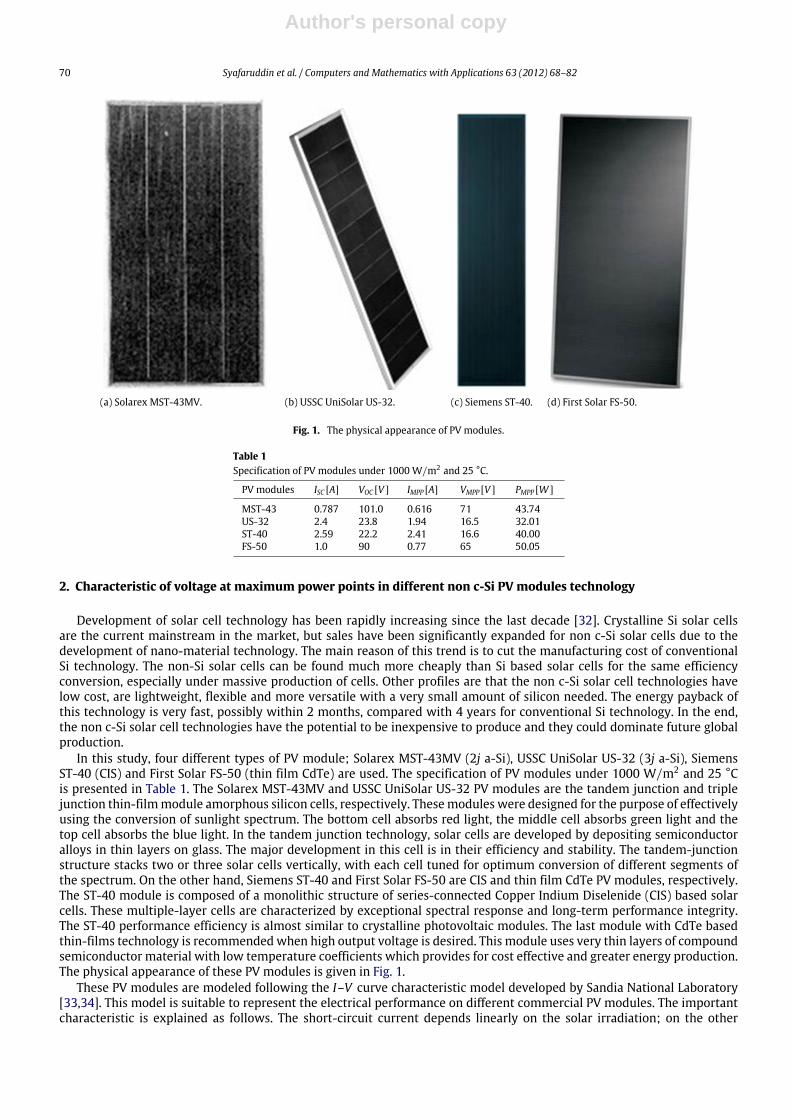
(a) Solarex MST-43MV. (b) USSC UniSolar US-32. (c) Siemens ST-40. (d) First Solar FS-50.
Fig. 1. The physical appearance of PV modules.
Table 1Specification of PV modules under 1000 W/m2 and 25 °C.
PV modules ISC [A] VOC [V ] IMPP [A] VMPP [V ] PMPP [W ]
MST-43 0.787 101.0 0.616 71 43.74US-32 2.4 23.8 1.94 16.5 32.01ST-40 2.59 22.2 2.41 16.6 40.00FS-50 1.0 90 0.77 65 50.05
2. Characteristic of voltage at maximum power points in different non c-Si PV modules technology
Development of solar cell technology has been rapidly increasing since the last decade [32]. Crystalline Si solar cellsare the current mainstream in the market, but sales have been significantly expanded for non c-Si solar cells due to thedevelopment of nano-material technology. The main reason of this trend is to cut the manufacturing cost of conventionalSi technology. The non-Si solar cells can be found much more cheaply than Si based solar cells for the same efficiencyconversion, especially under massive production of cells. Other profiles are that the non c-Si solar cell technologies havelow cost, are lightweight, flexible and more versatile with a very small amount of silicon needed. The energy payback ofthis technology is very fast, possibly within 2 months, compared with 4 years for conventional Si technology. In the end,the non c-Si solar cell technologies have the potential to be inexpensive to produce and they could dominate future globalproduction.
In this study, four different types of PV module; Solarex MST-43MV (2j a-Si), USSC UniSolar US-32 (3j a-Si), SiemensST-40 (CIS) and First Solar FS-50 (thin film CdTe) are used. The specification of PV modules under 1000 W/m2 and 25 °Cis presented in Table 1. The Solarex MST-43MV and USSC UniSolar US-32 PV modules are the tandem junction and triplejunction thin-filmmodule amorphous silicon cells, respectively. Thesemodules were designed for the purpose of effectivelyusing the conversion of sunlight spectrum. The bottom cell absorbs red light, the middle cell absorbs green light and thetop cell absorbs the blue light. In the tandem junction technology, solar cells are developed by depositing semiconductoralloys in thin layers on glass. The major development in this cell is in their efficiency and stability. The tandem-junctionstructure stacks two or three solar cells vertically, with each cell tuned for optimum conversion of different segments ofthe spectrum. On the other hand, Siemens ST-40 and First Solar FS-50 are CIS and thin film CdTe PV modules, respectively.The ST-40 module is composed of a monolithic structure of series-connected Copper Indium Diselenide (CIS) based solarcells. These multiple-layer cells are characterized by exceptional spectral response and long-term performance integrity.The ST-40 performance efficiency is almost similar to crystalline photovoltaic modules. The last module with CdTe basedthin-films technology is recommendedwhen high output voltage is desired. This module uses very thin layers of compoundsemiconductor material with low temperature coefficients which provides for cost effective and greater energy production.The physical appearance of these PV modules is given in Fig. 1.
These PV modules are modeled following the I–V curve characteristic model developed by Sandia National Laboratory[33,34]. This model is suitable to represent the electrical performance on different commercial PV modules. The importantcharacteristic is explained as follows. The short-circuit current depends linearly on the solar irradiation; on the other
Author's personal copy
Syafaruddin et al. / Computers and Mathematics with Applications 63 (2012) 68–82 71
(a) Solarex MST-43MV (2j a-Si). (b) USSC UniSolar US-32 (3j a-Si).
(c) Siemens ST-40 (CIS). (d) First Solar FS-50 (thin film CdTe).
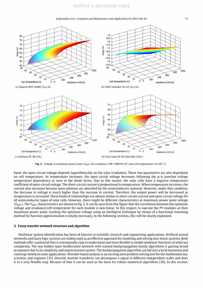
Fig. 2. Voltage at maximum power point (VMPP ) for irradiance (100–1000 W/m2) and cell temperature (10–60 °C).
hand, the open-circuit voltage depends logarithmically on the solar irradiation. These two parameters are also dependanton cell temperature. As temperature increases, the open circuit voltage decreases following the p–n junction voltagetemperature dependency as seen in the diode factor. Due to this reason, the solar cells have a negative temperaturecoefficient of open-circuit voltage. The short-circuit current is proportional to temperature.When temperature increases, thecurrent also increases because more photons are absorbed by the semiconductor material. However, under this condition,the decrease in voltage is much higher than the increase in current. Therefore, the output power will be decreased astemperature is increased. These kinds of relationships are almost similar in short-circuit current and open-circuit voltage forall semiconductor types of solar cells. However, there might be different characteristics at maximum power point voltage(VMPP). The VMPP characteristics are shown in Fig. 2. It can be seen from this figure that the correlation between the optimumvoltage and irradiance/cell temperature for each module is non-linear. In this respect, to operate the PV modules at theirmaximum power point, tracking the optimum voltage using an intelligent technique by means of a functional reasoningmethod for function approximation is totally necessary. In the following sections, this will be clearly explained.
3. Fuzzy wavelet network structure and algorithm
Nonlinear system identification has been of interest in scientific research and engineering applications. Artificial neuralnetworks and fuzzy logic systems arewidely used as an effective approach formodeling and solving non-linear systems. Bothmethods offer a potential that is conceptually easy to understand andmore flexible tomodel nonlinear functions of arbitrarycomplexity. The one hidden layer feedforward network with trained backpropagation family algorithms is gaining broadacceptance due to its simplicity and expressiveness power. The backpropagation algorithm can fall into a localminimumandconverge slowly in someapplications.Wavelet-based analysis is an excitingnewproblemsolving tool for themathematician,scientist, and engineer [35]. Discrete wavelet transform can decompose a signal at different independent scales and doesit in a very flexible way. Because of that it can be used as the basis for robust numerical algorithms [36]. In this section,
Author's personal copy
72 Syafaruddin et al. / Computers and Mathematics with Applications 63 (2012) 68–82
the structure of the FWN that consists of a set of fuzzy rules is described [3]. The FWN might avoid a local minimum. Forpractical implementations, infinite wavelet frames must be truncated into finite sets.
The fuzzy rule has a form as follows;
Rj: IF x1 is Aj,1 AND x2 is Aj,2 AND . . . xn is Aj,n THEN yj =
L−k=−L
fk(x) j: 1, 2, . . . ,M (1)
where
fk(x) =
K−m=0
dj,k,mn∏
i=1
2m/2ψ(2mxi − k). (2)
The variables m and k are integers that scale and translate the mother function, ψ(x), to generate a family of discretewavelets. The scale index m indicates the wavelet’s width, and location index k gives its position. For each increasingindex m, a higher or finer resolution function is added, which adds increasing detail [35,36]. The FWN has a differentstructure and each rule consists of (K + 1) ∗ (2 ∗ L + 1) wavelet functions. For this structure, where M, L, and K are fixedparameters and expansion coefficients (dj,k,m) are free parameters to be tunedwhenmapping the input–output relationship.The parameters L and K determine the size of the wavelet for the jth fuzzy rule. For this FWN, the Mexican Hat waveletfunction ψ(x) = (1 − 2x2) exp(−x2)was selected as our wavelet function.
In the second stage of the FWN, the inputs of a system are codified into linguistic values, the set of Gaussianmembershipfunctions attributed to each variable. The third stage calculates to each rule Rj its respective activation degree. The FWNsystems have a mathematical model that resembles that of a three-layer network, fuzzification, fuzzy inference, anddefuzzification [3]. By applying fuzzy product inference engine, singleton fuzzifier, center average defuzzifier, and theGaussian membership functions process, the output of FWN becomes:
y =
M∑j=1
n∏i=1µj,i(xi)yj,i(xi)
M∑j=1
n∏i=1µj,i(xi)
(3)
whereµj,i(x) = exp(−((x− xc j,i)/σj,i)2), xc j,i denote the centers and σj,i denote the standard deviation for the membershipfunction associated with rule j. After determination of the structure, the next step is to optimize the network’s parameters.In this network, the centers of fuzzy membership function, standard deviations of membership function and expansioncoefficients of wavelet function are free parameters, consequently the total free unknown parameter number is 2 ∗ n ∗M +
M ∗ ((2 ∗ L + 1) ∗ (K + 1)), where M and n are fuzzy rule number and variable number of the function respectively. Thedesigning fuzzy system is now equivalent to determining these parameters. In this work, our task is to design the fuzzywavelet system y(x) in the form of Eq. (3) such that the matching error
E =12
N−p=1
(y(xp)− ypd)2 (4)
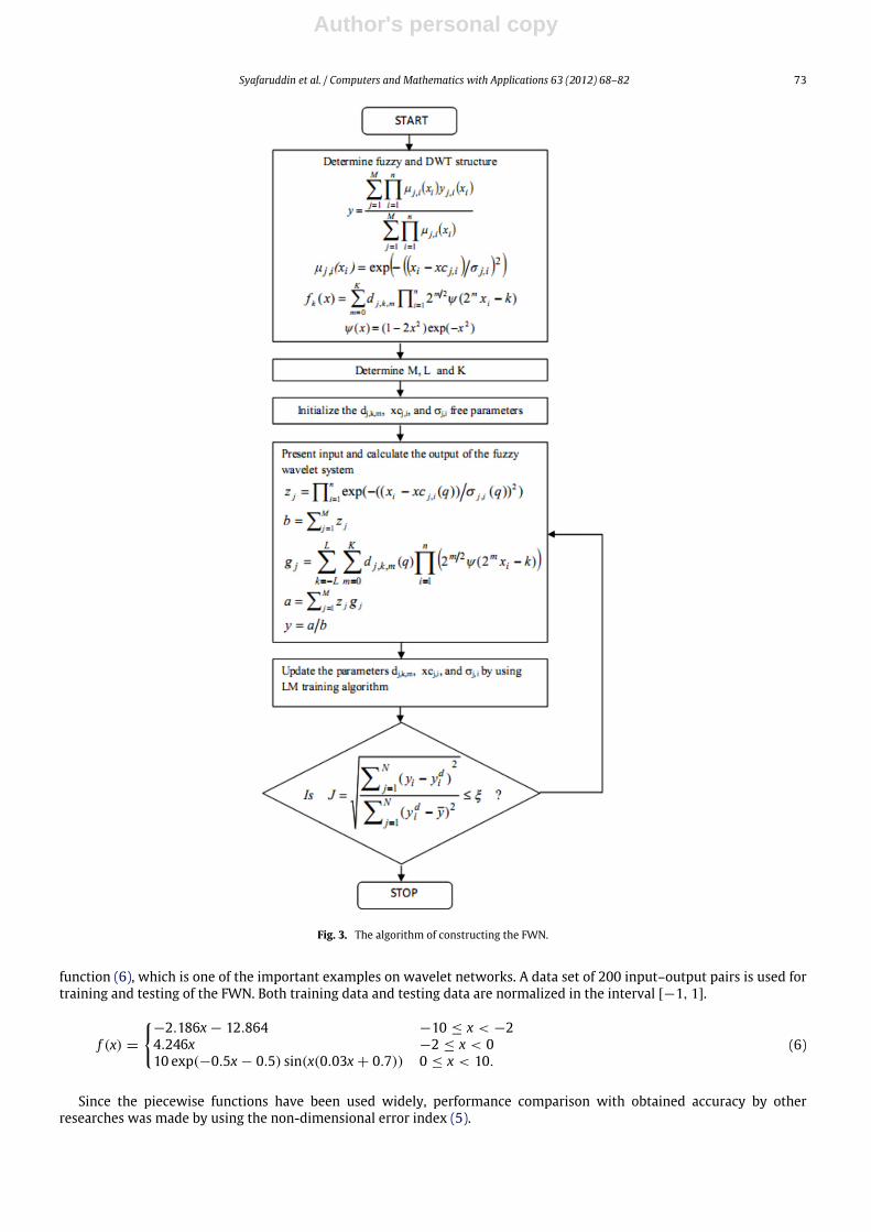
isminimized, whereN is the length of input–output pairs and ypd is desired output value at xp. That is, the task is to determinethe free parameters such that E of (4) is minimized. To determine these parameters, the fuzzy system is represented as afeedforwardnetwork. Levenberg–Marquardt (LM) algorithmFletcher strategy is used for tuning these parameters. The entirevalue of a given system is normalized between−1 and+1. The systemparameterswere initialized to linearly equally spacedpoints between 0 and 1. Only the membership function’s standard deviation parameters were initialized to 1. The learningalgorithm of the used FWN can be summarized in Fig. 3.
Since the given system is normalized, a dimensionless performance index (J) formulated as follows is introduced forperformance measurement during the testing,
J =
N∑i−1(yi − ydi )2
N∑i(ydi − y)2
with y =1N
N−i=1
ydi (5)
where N is the number of the parameter data set, i is the ith sample of data, ydi is the desired output and yi is the estimatedoutput from FWN.
In the literature, several fuzzy and neural wavelet networks have been proposed for several functions [36–48]. In thispaper, the performance of the FWNwith otherWNNand FWNcan be seen in Table 2 for the below single variable benchmark
Author's personal copy
Syafaruddin et al. / Computers and Mathematics with Applications 63 (2012) 68–82 73
Fig. 3. The algorithm of constructing the FWN.
function (6), which is one of the important examples on wavelet networks. A data set of 200 input–output pairs is used fortraining and testing of the FWN. Both training data and testing data are normalized in the interval [−1, 1].
f (x) =
−2.186x − 12.864 −10 ≤ x < −24.246x −2 ≤ x < 010 exp(−0.5x − 0.5) sin(x(0.03x + 0.7)) 0 ≤ x < 10.
(6)
Since the piecewise functions have been used widely, performance comparison with obtained accuracy by otherresearches was made by using the non-dimensional error index (5).
Author's personal copy
74 Syafaruddin et al. / Computers and Mathematics with Applications 63 (2012) 68–82
Table 2Comparison of different models for the benchmark function.
Model Performance index (J) References
Zhang and Beveniste 0.05057 [4]Chen and Bruns 0.0480 [36]Yao et al. 0.03 [37]Song and Qi 0.04 [38]Safavi et al. 0.0072 [39]Ho et al. 0.021 [40]Srivastava et al. 0.0108 [41]Srivastava et al. 0.0014 [41]Karatepe and Alci 0.00957 [3]Wang et al. 0.03 [42]Sadati and Marami 0.00101 [43]Singh et al. 0.0093 [44]Singh et al. 0.0006 [44]Tzeng 0.0303 [45]Ebadat et al. 0.0071 [46]Zainuddin and Pauline 1.90974e − 014 [47]
4. Performance comparison for optimum operating point of PV modules
In this section, the performance of FWN is comparedwith three different ANN structures, for instance radial basis function(RBF) neural network, adaptive neuro-fuzzy inference system (ANFIS) and three layered feed-forward neural network (TFFN)for estimating optimum operating points of different PV module technologies. The configurations have two input signals;irradiance level (E) and cell temperature (Tc) and a single output signal;MPP voltage (VMPP). The network configurations andepoch number are determined according to the performance index (J). For that case, the desired output is the ideal voltage atmaximumpower point (VMPP), Vop is the estimated optimum voltage and VMPP is the average of VMPP . There are 228 numbersof training data sets, between 100–1000 W/m2 and 10–65 °C, to cover the entire domain problems as VMPP = f (E, Tc). Thetrainings were terminated when the error of the test sets were beginning to increase.
In theoretical manner, there can be an unlimited number of unknown parameters in an intelligence system. However,when mapping an input–output data by using an ANN based method, the number of the parameters should be keptreasonably small for successful identification of a structure, avoiding exponential computational complexity. In otherwords,this means that the computational effort depends upon the number of unknown parameters, but nevertheless a greaternumber of free parameters does not mean that a desired approximation accuracy of a network can be obtained. For thisreason, we will observe and discuss the performance of the ANN methods by increasing the number of parameters to getenough estimation accuracy.
The RBF neural network is a typical neural network structure using local mapping instead of global mapping as in multilayer perceptron (MLP) [49]. In the MLP method, all inputs cause an output, while in the RBF method; only inputs neara receptive field produce an activation function. The hidden layer is locally tuned neurons centered over receptive fields.Receptive fields are located in the input space areas where input vectors exist. If an input vector lies near the center of areceptive field, then that hidden layer will be activated. The training process using an RBF network is very simple. Oncethe goal error is set, the training is stopped and the number of hidden nodes is confirmed. The epoch for training in an RBFnetwork depends on the complexity of input–output relationships. If they are simple, then the training is terminated witha small number of neurons, or vice versa. In this study, the training iteration number (epoch) is set between 25 and 30 anddepends on the type of PV modules. In the training process, the hidden nodes are obtained by adding one by one neuron intime until the performance of the network falls beneath an error goal. In this study, the parameter of the training process:the mean squared error goal (GOAL), spread of radial basis functions (SPREAD), maximum number of neurons (MN) and thenumber of neurons to add between displays (DF) are 0.003, 1.0, 228, 1, respectively.
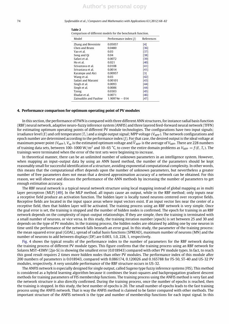
Fig. 4 shows the typical results of the performance index to the number of parameters for the RBF network duringthe training process of different PV module types. This figure confirms that the training process using an RBF network forSolarexMST-43MV (2ja-Si) is showing the smallest error (0.018943) compared with other PVmodule types. In fact, to reachthis good result requires 2 times more hidden nodes than other PV modules. The performance index of this module after200 numbers of parameters is 0.018943, compared with 0.086174, 0.120026 and 0.165788 for FS-50, ST-40 and US-32 PVmodules, respectively. A very unstable performance of the RBF structure occurs in US-32.
The ANFIS network is especially designed for single output, called Sugeno type fuzzy inference systems (FIS). Thismethodis considered as a hybrid learning algorithm because it combines the least-squares and backpropagation gradient descentmethods for training parameters of FIS membership functions. The training process using the ANFIS method is very fast andthe network structure is also directly confirmed. During the training process, once the number of epochs is reached, thenthe training is stopped. In this study, the best number of epochs is 20. The small number of epochs leads to the fast trainingprocess using the ANFIS network. That is way the ANFIS method is claimed to be faster compared with other methods. Theimportant structure of the ANFIS network is the type and number of membership functions for each input signal. In this
Author's personal copy
Syafaruddin et al. / Computers and Mathematics with Applications 63 (2012) 68–82 75
Fig. 4. Training performance index versus number of parameters for the RBF network.
Fig. 5. Training performance index versus number of parameters for the ANFIS network.
study, the generalized bell membership function ‘gbellmf’ is set for each input. More accuracy can be reached using thisnetwork by adding the number of membership functions for each input, but the simulation progress becomes very slow.
Fig. 5 presents the performance index result during the training process using the ANFIS network for different PVmoduletypes. It is clear from this figure that this ANN structure is more suitable for US-32 where the lowest error of 0.015515compared with other PV module types. This result implies that this method can overcome the problem during the trainingprocess as in RBF network. The similar performance can be found for MST-43MV and ST-40 using the ANFIS network.However, the highest training error still occurs in FS-50 PV modules when using the ANFIS network.
The remaining ANN structure is the TFFN method. This method uses backpropagation gradient descent methods foradjusting the weights in order to reduce the learning error [50]. Once the error gradient is calculated, the weights areadjusted. In thismethod, there aremany possibilities to construct this network. Therefore, the selection of network structureis based on the intuitive thinking of the trainer. In this respect, the training process takes much time. In this study, whenthe ‘logsig’ function utilized an activation function between layers, the performance became better than the other types ofactivation functions. Other important factors during the training of the TFFN network are the learning andmomentum rates.The learning rate means how much the weight is changed at each step. If this rate is too small, the output training will bevery precise, but the algorithmwill take a long time to converge. On the other hand, if too large, the outputs will be bouncingaround and the algorithm may diverge. The momentum rate is related to the time when the weights are updated. This rateis commonly determined by trial and error [51]. In this study, the learning andmomentum rate are specified to 0.2 and 0.85,respectively. In addition, the training process using the TFFN network could be very slow due to the very high number ofepochs to be set. To reach such outcomes in this study, the epoch number is specified at 50,000.
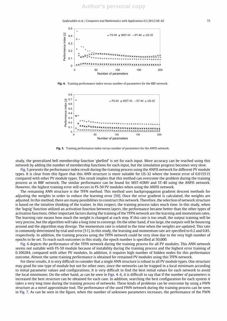
Fig. 6 depicts the performance of the TFFN network during the training process for all PV modules. This ANN networkseems not suitable with FS-50 module because of instability during the training process and the highest error training of0.100284, compared with other PV modules. In addition, it requires high number of hidden nodes for this performanceoutcome. Almost the same training performance is obtained for remained PV modules using this TFFN network.
For these results, it is very difficult to consider that a single ANN structure is robust to all PVmodule types. One structuremay good for one type of module but not for other ones, since the networks can be trapped in a local minimum accordingto initial parameter values and configurations. It is very difficult to find the best initial values for each network to avoidthe local minimums. On the other hand, as can be seen in Figs. 4–6, it is difficult to say that if the number of parameters isincreased the best structure can be obtained for each case. In addition, searching the best configuration for each system ittakes a very long time during the training process of networks. These kinds of problems can be overcome by using a FWNstructure as a novel approximate tool. The performance of the used FWN network during the training process can be seenin Fig. 7. As can be seen in the figure, when the number of unknown parameters increases, the performance of the FWN
Author's personal copy
76 Syafaruddin et al. / Computers and Mathematics with Applications 63 (2012) 68–82
Fig. 6. Training performance index versus number of parameters for the TFFN network.
FS-50MST-43ST-40US-32
Number of parameters
Per
form
ance
inde
x (J
)
0 20 40 60 80 100 120
101
100
10–1
10–2
10–3
10–4
Fig. 7. Training performance index versus number of parameters for the FWN network.
Number of iterations
Per
form
ance
inde
x (J
)
0 5 10 15 20 25 30 35 40 45 50
FS-50MST-43ST-40US-32
102
100
10–2
10–4
Fig. 8. Training performance index versus number of iterations for the FWN network.
is getting better. Wavelets represent a special class of functions that can generate bases in functional vector spaces. If thenumbers of wavelets or fuzzy rules are increased in the FWN, it results in more parameters and more computation, but cangive better approximation accuracy than the other networks.
The training performance index and all network structures for all PVmodule types are summarized in Table 3. The optimalsize of the FWN is determined for each solar cell technology by observing the performance index. Consequently, all caseswere trained by using the FWN with 114 unknown free parameters which are constituted by taking as M = 6, K = 4, andL = 1 in the Eq. (1). At each training epoch, the performance index is calculated for both the training set and the test set.The training procedure is applied iteratively until a specified error goal is met. The algorithm converges very quickly andepoch number is 50 for all cases and the relationship between the training performance index of FWN and the number ofthe iteration is given in Fig. 8.
After the training process, the proposed method is validated with four different scenarios in order to show the learningcapability of the networks for the new data sets. These operating conditions may represent the daily operation conditionofthe PV system. These operating conditions are obtained by using ramp, random number, repeating sequence and uniformrandom number signals. The ramp and repeating sequence signals represent the quick changes in irradiance and celltemperature, while the other two signals represent the slow changes in irradiance and cell temperature. The input signals
Author's personal copy
Syafaruddin et al. / Computers and Mathematics with Applications 63 (2012) 68–82 77
Table 3Performance index of training process and network structures.
PV modules RBF ANFIS TFFN FWNnh J nh J nh J M K L J
MST-43MV 12 0.018943 21 0.064521 4 0.037144 6 4 1 0.00092537US-32 4 0.165788 21 0.015515 4 0.072516 6 4 1 0.00029961ST-40 5 0.120026 21 0.053423 4 0.058335 6 4 1 0.00028179FS-50 11 0.086174 21 0.15079 7 0.100284 6 4 1 0.00073969
PV
Mod
ule
Vol
tage
[V]
Time [sec]
68
67
66
65
64
63
62
611 2 3 4 5 6 7 8 9 10
PV
Mod
ule
Vol
tage
[V]
Time [sec]
63.85
63.8
63.75
63.7
63.65
63.6
63.55
63.5
63.45
63.4
63.351 2 3 4 5 6 7 8 9 10
(a) Ramp signal. (b) Random signal.
PV
Mod
ule
Vol
tage
[V]
1 2 3 4 5 6 7 8 9 10
Time [sec]
68
67
66
65
64
63
62
61
Time [sec]
PV
Mod
ule
Vol
tage
[V]
68
67
66
65
64
63
62
611 2 3 4 5 6 7 8 9 10
(c) Repeating sequence signal. (d) Uniform random signal.
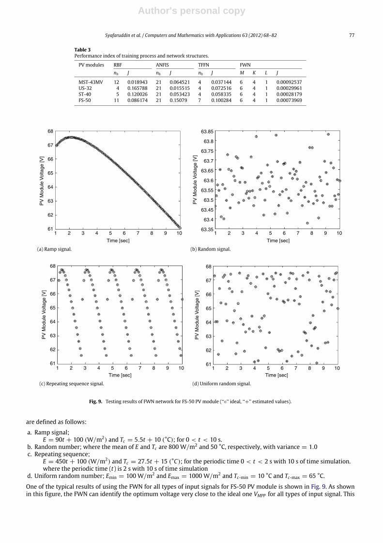
Fig. 9. Testing results of FWN network for FS-50 PV module (‘‘◦’’ ideal, ‘‘+’’ estimated values).
are defined as follows:
a. Ramp signal;E = 90t + 100 (W/m2) and Tc = 5.5t + 10 (°C); for 0 < t < 10 s.
b. Random number; where the mean of E and Tc are 800 W/m2 and 50 °C, respectively, with variance = 1.0c. Repeating sequence;
E = 450t + 100 (W/m2) and Tc = 27.5t + 15 (°C); for the periodic time 0 < t < 2 s with 10 s of time simulation.where the periodic time (t) is 2 s with 10 s of time simulation
d. Uniform random number; Emin = 100 W/m2 and Emax = 1000 W/m2 and Tc-min = 10 °C and Tc-max = 65 °C.
One of the typical results of using the FWN for all types of input signals for FS-50 PV module is shown in Fig. 9. As shownin this figure, the FWN can identify the optimum voltage very close to the ideal one VMPP for all types of input signal. This
Author's personal copy
78 Syafaruddin et al. / Computers and Mathematics with Applications 63 (2012) 68–82P
V M
odul
e V
olta
ge [V
]
Time [sec]
68
67
66
65
64
63
62
610 1 2 3 4 5 6 7 8 9 10
PV
Mod
ule
Vol
tage
[V]
63.85
63.8
63.75
63.7
63.65
63.6
63.55
63.5
63.45
63.4
63.350 1 2 3 4 5 6 7 8 9 10
Time [sec]
(a) Ramp signal. (b) Random signal.
PV
Mod
ule
Vol
tage
[V]
68
67
66
65
64
63
62
610 1 2 3 4 5 6 7 8 9 10
Time [sec]
PV
Mod
ule
Vol
tage
[V]
Time [sec]
0 1 2 3 4 5 6 7 8 9 10
68
67
66
65
64
63
62
61
(c) Repeating sequence signal. (d) Uniform random signal.
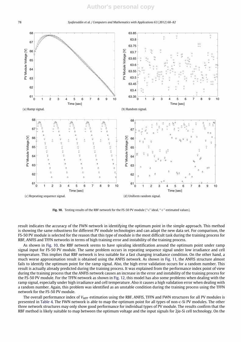
Fig. 10. Testing results of the RBF network for the FS-50 PV module (‘‘◦’’ ideal, ‘‘+’’ estimated values).
result indicates the accuracy of the FWN network in identifying the optimum point in the simple approach. This methodis showing the same robustness for different PV module technologies and can adapt the new data set. For comparison, theFS-50 PV module is selected for the reason that this type of module is the most difficult task during the training process forRBF, ANFIS and TFFN networks in terms of high training error and instability of the training process.
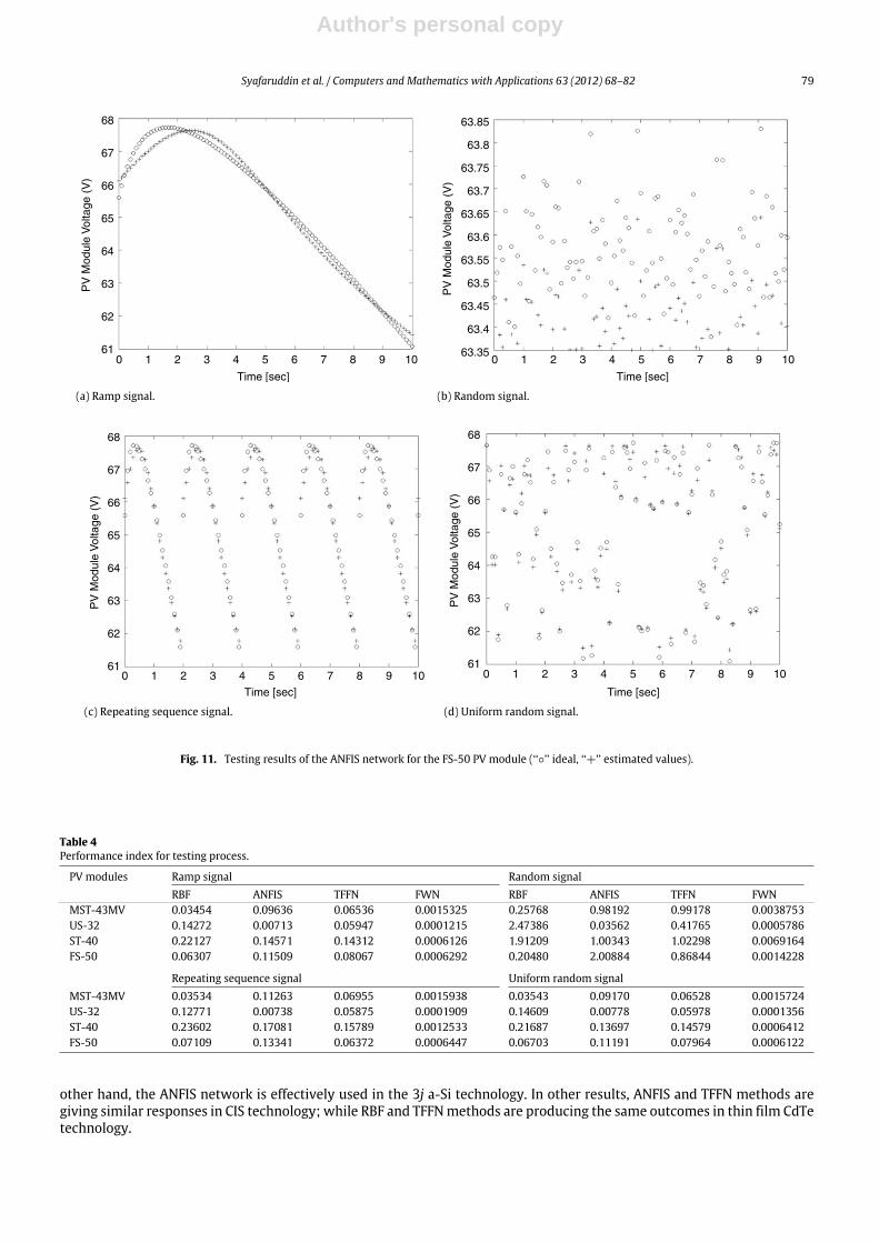
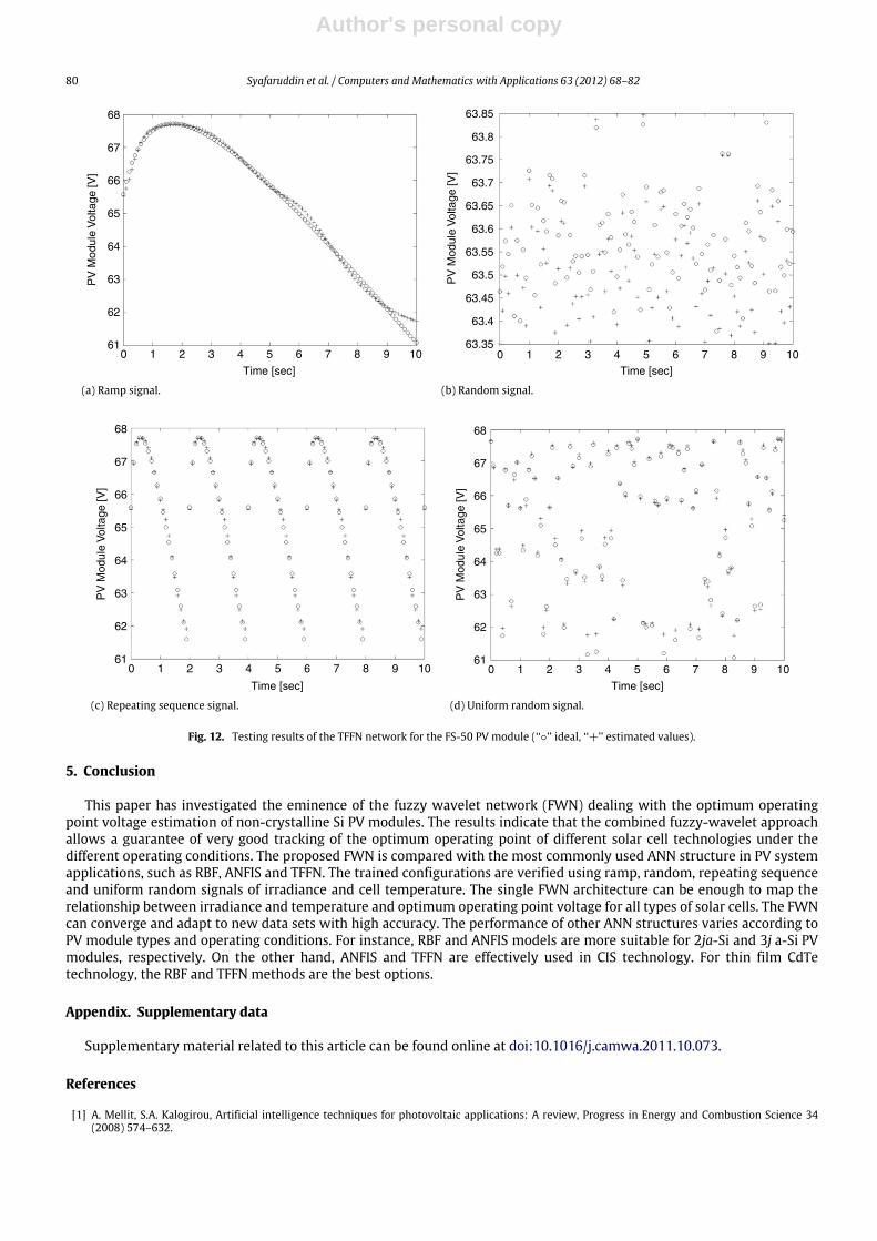
As shown in Fig. 10, the RBF network seems to have spiraling identification around the optimum point under rampsignal input for FS-50 PV module. The same problem occurs in repeating sequence signal under low irradiance and celltemperature. This implies that RBF network is less suitable for a fast changing irradiance condition. On the other hand, amuch worse approximation result is obtained using the ANFIS network. As shown in Fig. 11, the ANFIS structure almostfails to identify the optimum point for the ramp signal. Also, the high error validation occurs for a random number. Thisresult is actually already predicted during the training process. It was explained from the performance index point of viewduring the training process that the ANFIS network causes an increase in the error and instability of the training process forthe FS-50 PV module. For the TFFN network as shown in Fig. 12, this model has also some problems when dealing with theramp signal, especially under high irradiance and cell temperature. Also it causes a high validation error when dealing witha random number. Again, this problem was identified as an unstable condition during the training process using the TFFNnetwork for the FS-50 PV module.
The overall performance index of VMPP estimation using the RBF, ANFIS, TFFN and FWN structures for all PV modules ispresented in Table 4. The FWN network is able to map the optimum point for all types of non-c-Si PV modules. The otherthree network structures may only show good performance for individual types of PV module. The results confirm that theRBF method is likely suitable to map between the optimum voltage and the input signals for 2ja-Si cell technology. On the
Author's personal copy
Syafaruddin et al. / Computers and Mathematics with Applications 63 (2012) 68–82 79P
V M
odul
e V
olta
ge (
V)
68
67
66
65
64
63
62
61
Time [sec]
0 1 2 3 4 5 6 7 8 9 10
Time [sec]
PV
Mod
ule
Vol
tage
(V
)
63.85
63.8
63.75
63.7
63.65
63.6
63.55
63.5
63.45
63.4
63.350 1 2 3 4 5 6 7 8 9 10
(a) Ramp signal. (b) Random signal.
Time [sec]
PV
Mod
ule
Vol
tage
(V
)
68
67
66
65
64
63
62
610 1 2 3 4 5 6 7 8 9 10
Time [sec]
PV
Mod
ule
Vol
tage
(V
)
68
67
66
65
64
63
62
610 1 2 3 4 5 6 7 8 9 10
(c) Repeating sequence signal. (d) Uniform random signal.
Fig. 11. Testing results of the ANFIS network for the FS-50 PV module (‘‘◦’’ ideal, ‘‘+’’ estimated values).
Table 4Performance index for testing process.
PV modules Ramp signal Random signalRBF ANFIS TFFN FWN RBF ANFIS TFFN FWN
MST-43MV 0.03454 0.09636 0.06536 0.0015325 0.25768 0.98192 0.99178 0.0038753US-32 0.14272 0.00713 0.05947 0.0001215 2.47386 0.03562 0.41765 0.0005786ST-40 0.22127 0.14571 0.14312 0.0006126 1.91209 1.00343 1.02298 0.0069164FS-50 0.06307 0.11509 0.08067 0.0006292 0.20480 2.00884 0.86844 0.0014228
Repeating sequence signal Uniform random signalMST-43MV 0.03534 0.11263 0.06955 0.0015938 0.03543 0.09170 0.06528 0.0015724US-32 0.12771 0.00738 0.05875 0.0001909 0.14609 0.00778 0.05978 0.0001356ST-40 0.23602 0.17081 0.15789 0.0012533 0.21687 0.13697 0.14579 0.0006412FS-50 0.07109 0.13341 0.06372 0.0006447 0.06703 0.11191 0.07964 0.0006122
other hand, the ANFIS network is effectively used in the 3j a-Si technology. In other results, ANFIS and TFFN methods aregiving similar responses in CIS technology; while RBF and TFFNmethods are producing the same outcomes in thin film CdTetechnology.
Author's personal copy
80 Syafaruddin et al. / Computers and Mathematics with Applications 63 (2012) 68–82
Time [sec]
PV
Mod
ule
Vol
tage
[V]
68
67
66
65
64
63
62
610 1 2 3 4 5 6 7 8 9 10
Time [sec]
PV
Mod
ule
Vol
tage
[V]
63.85
63.8
63.75
63.7
63.65
63.6
63.55
63.5
63.45
63.4
63.350 1 2 3 4 5 6 7 8 9 10
(a) Ramp signal. (b) Random signal.
Time [sec]
PV
Mod
ule
Vol
tage
[V]
68
67
66
65
64
63
62
610 1 2 3 4 5 6 7 8 9 10
Time [sec]
PV
Mod
ule
Vol
tage
[V]
68
67
66
65
64
63
62
610 1 2 3 4 5 6 7 8 9 10
(c) Repeating sequence signal. (d) Uniform random signal.
Fig. 12. Testing results of the TFFN network for the FS-50 PV module (‘‘◦’’ ideal, ‘‘+’’ estimated values).
5. Conclusion
This paper has investigated the eminence of the fuzzy wavelet network (FWN) dealing with the optimum operatingpoint voltage estimation of non-crystalline Si PV modules. The results indicate that the combined fuzzy-wavelet approachallows a guarantee of very good tracking of the optimum operating point of different solar cell technologies under thedifferent operating conditions. The proposed FWN is compared with the most commonly used ANN structure in PV systemapplications, such as RBF, ANFIS and TFFN. The trained configurations are verified using ramp, random, repeating sequenceand uniform random signals of irradiance and cell temperature. The single FWN architecture can be enough to map therelationship between irradiance and temperature and optimum operating point voltage for all types of solar cells. The FWNcan converge and adapt to new data sets with high accuracy. The performance of other ANN structures varies according toPV module types and operating conditions. For instance, RBF and ANFIS models are more suitable for 2ja-Si and 3j a-Si PVmodules, respectively. On the other hand, ANFIS and TFFN are effectively used in CIS technology. For thin film CdTetechnology, the RBF and TFFN methods are the best options.
Appendix. Supplementary data
Supplementary material related to this article can be found online at doi:10.1016/j.camwa.2011.10.073.
References
[1] A. Mellit, S.A. Kalogirou, Artificial intelligence techniques for photovoltaic applications: A review, Progress in Energy and Combustion Science 34(2008) 574–632.

Author's personal copy
Syafaruddin et al. / Computers and Mathematics with Applications 63 (2012) 68–82 81
[2] A. Mellit, S.A. Kalogirou, L. Hontoria, S. Shaari, Artificial intelligence techniques for sizing photovoltaic systems: A review, Renewable and SustainableEnergy Reviews 13 (2009) 406–419.
[3] E. Karatepe, M. Alci, A new approach to fuzzy wavelet system modeling, International Journal of Approximate Reasoning 40 (2005) 302–322.[4] Q. Zhang, A. Beveniste, Wavelet networks, IEEE Transactions on Neural Networks 3 (1992) 889–898.[5] S. Yilmaz, Y. Oysal, Fuzzywavelet neural networkmodels for prediction and identification of dynamical systems, IEEE Transactions onNeural Networks
21 (2010) 1599–1609.[6] M. Davanipoor, M. Zekri, F. Sheikholeslam, Fuzzy wavelet neural networks with hybrid algorithm in nonlinear system identification, in: Proceeding
of the 2011 IEEE International Conference on Computer Science and Automation Engineering, 2011, pp. 153–156.[7] A. Ebadat, N. Noroozi, A.A. Safavi, S.H. Mousavi, New fuzzy wavelet network for modeling and control: The modeling approach, Communications in
Nonlinear Science and Numerical Simulation 16 (2011) 3385–3396.[8] A. Al-Khazraji, N. Essounbouli, A. Hamzaoui, A robust adaptive fuzzy wavelet network based controller for a class of non-linear systems, International
Journal of Modelling, Identification and Control 12 (2011) 290–303.[9] N. Sadati, B. Marami, Fuzzy wavelet modeling using data clustering, in: Proceedings of the IEEE Symposium on Computational Intelligence and Data
Mining, 2007, pp. 114–119.[10] M. Shangchang, T. Zanma, M. Ishida, Identification of human skill and its application to an automatic driving system—An approach from hybrid
dynamical system, IECON Proceedings on Industrial Electronics Conference (2006) 400–405.[11] F. Giraud, Z.M. Salameh, Analysis of the effects of a passing cloud on a grid-interactive photovoltaic systemwith battery storage using neural networks,
IEEE Transactions on Energy Conversion 14 (1999) 1572–1577.[12] X. Sun,W.Wu, X. Li, Q. Zhao, A research on photovoltaic energy controlling systemwithmaximumpower point tracking, IEEE Proceeding of the Power
Conversion Conference (2002) 822–826.[13] A. Mellit, M. Benghanem, S.A. Kalogirou, An adaptive wavelet-network model for forecasting daily total solar-radiation, Applied Energy 83 (2006)
705–722.[14] B. Cao, L. Chang, H. Li, Implementation of the RBF neural network on a SOPC for maximum power point tracking, in: Proceeding of the Canadian
Conference on Electrical and Computer Engineering, 2008, pp. 981–985.[15] A. Yona, T. Senjyu, A.Y. Saber, T. Funabashi, H. Sekine, K. Chul-Hwan, Application of neural network to 24-h-ahead generating power forecasting for
PV system, in: Proceeding of the Power and Energy Society General Meeting–Conversion and Delivery of Electrical Energy in the 21st Century, 2008,pp. 1–6.
[16] S. Zhou, L. Kang, G. Guo, Y. Zhang, J. Cao, B. Cao, The application of combinatorial optimization by genetic algorithm and neural network, in: Proceedingof the 3rd IEEE Conference on Industrial Electronics and Applications, 2008, pp. 227–231.
[17] S. Zhou, L. Kang, G. Guo, Y. Zhang, B. Cao, The combinatorial optimization by genetic algorithm and neural network for energy storage system in solarenergy electric vehicle, in: Proceeding of the 7th World Congress on Intelligent Control and Automation, 2008, pp. 2838–2842.
[18] A. Varnham, A.M. Al-Ibrahim,G.S. Virk, D. Azzi, Soft-computingmodel-based controllers for increasedphotovoltaic plant efficiencies, IEEE Transactionson Energy Conversion 22 (2007) 873–880.
[19] A.Mellit, S.A. Kalogirou, Neuro-fuzzy basedmodeling for photovoltaic power supply system, in: Proceeding of the First International Power and EnergyConference, 2006, pp. 88–93.
[20] J.S. Choi, D.Y. Kim, K.T. Park, J.H. Choi, D.H. Chung, Tracking system and MPPT control for efficiency improvement of photovoltaic, in: Proceeding ofthe International Conference on Control, Automation and Systems, 2008, pp. 1341–1344.
[21] Y. Narri, V. Mummadi, Adaptive controller for PV supplied buck-boost converter, in: Proceeding of the IEEE International Conference on PowerElectronics and Drive Systems, 1999, pp. 789–793.
[22] K. Jae-Sub, J. Byung-Jin, P. Ki-Tae, C. Chung-Hoon, C. Dong-Hwa, Maximum power point tracking control of PV system for DCmotors drive with neuralnetwork, in: Proceeding of the International Conference on Smart Manufacturing Application, 2008, pp. 514–519.
[23] A. de Medeiros Torres, F.L.M. Antunes, F.S. dos Reis, An artificial neural network-based real time maximum power tracking controller for connectinga PV system to the grid, in: Proceeding of the 24th IEEE Annual Conference on Industrial Electronics Society, 1998, pp. 554–558.
[24] J.A. Momoh, Y. Wang, F. Eddy-Posey, Optimal power dispatch of photovoltaic systemwith random load, in: Proceeding of the IEEE Power EngineeringSociety General Meeting, 2004, pp. 1939–1945.
[25] S. Chakraborty, M.G. Simoes, PV-microgrid operational cost minimization by neural forecasting and heuristic optimization, in: Proceeding of the IEEEIndustry Applications Society Annual Meeting, 2008, pp. 1–8.
[26] S.I. Sulaiman, T.K. Abdul Rahman, I. Musirin, Optimizing one-hidden layer neural network design using evolutionary programming, in: Proceeding ofthe 5th International Colloquium on Signal Processing & Its Applications, 2009, pp. 288–293.
[27] G. Tina, G. Capizzi, Improved lead-acid batterymodeling for photovoltaic application by recurrent neural networks, in: Proceeding of the InternationalSymposium on Power Electronics, Electrical Drives, Automation and Motion, 2008, pp. 1170–1174.
[28] M.G. Villalva, J.R. Gazoli, E.R. Filho, Comprehensive approach tomodeling and simulation of photovoltaic arrays, IEEE Transactions on Power Electronics24 (2009) 1198–1208.
[29] H.G. Beyer, R. Gonschalg, T.R. Betts, D.G. Infield, Modeling the realistic short circuit current and MPP power of a-Si single and multijunction devices,in: Proceeding of the 3rd World Conference on Photovoltaic Energy Conversion, 2003, pp. 2435–2438.
[30] Syafaruddin, E. Karatepe, T. Hiyama, Polar coordinated fuzzy controller based real-time maximum power point control of photovoltaic system,Renewable Energy 34 (2009) 2597–2606.
[31] Syafaruddin, E. Karatepe, T. Hiyama, Artificial neural network polar coordinated fuzzy controller basedmaximum power point tracking control underpartially shaded conditions, IET Renewable Power Generation 3 (2009) 239–253.
[32] M. Thomson, D.G. Infield, Impact of widespread photovoltaics generation on distribution systems, IET Renewable Power Generation 1 (2007) 33–40.[33] D.L. King, Photovoltaic module and array performance characterization methods for all system operating conditions, in: Proceedings of NREL/SNL
Photovoltaics Program Review Meeting, 1997, pp. 1–22.[34] D.L. King, Sandia’s PV module electrical performance model, Sandia National Laboratories, September 2000.[35] C.B. Sidney, R.A. Gopineth, H. Guo, Introduction to Wavelets and Wavelet Transforms, Prentice Hall, 1998.[36] Junghui Chen, DuaneD. Bruns,WaveARXneural network development for system identification using a systematic design systematic design synthesis,
Industrial and Engineering Chemistry Research 34 (1995) 4420–4435.[37] S. Yao, C.J. Wei, Z.Y. He, Evolving wavelet neural networks for function approximation, Electronics Letters 32 (1996) 360–361.[38] X. Song, J. Chen, F. Qi, A new way of setting initial parameter value for fast convergence wavelet neural network used for signal or function
approximation, Journal of Infrared and Milimeter Waves 16 (1997) 33–38.[39] A.A. Safavi, J.A. Romagnoli, Application of wavelet based neural networks to modeling and optimization of an experimental distillation column,
Engineering Application of Artificial Intelligence 10 (1997) 301–313.[40] D.W.C. Ho, P.A. Zhang, J. Xu, Fuzzy wavelet networks for function learning, IEEE Transactions on Fuzzy Systems 9 (2001) 200–211.[41] S. Srivastava, M. Singh, M. Hanmandlu, A.N. Jha, New fuzzy wavelet neural networks for system identification and control, Applied Soft Computing 6
(2005) 1–17.[42] J. Wang, J. Xiao, H. Peng, X. Gao, Constructing fuzzy wavelet network modeling, International Journal of Information Technology 11 (2005) 68–74.[43] N. Sadati, B. Marami, Fuzzy wavelet modeling using data clustering, in: Proceedings of the IEEE Symposium on Computational Intelligence and Data
Mining, 2007, pp. 114–119.[44] M. Singh, S. Srivastava, M. Hanmandlu, J.R.P. Gutpa, Type-2 fuzzy wavelet networks (T2FWN) for system identification using fuzzy differential and
Lyapunovstability algorithm, Applied Soft Computing 9 (2009) 977–989.

Author's personal copy
82 Syafaruddin et al. / Computers and Mathematics with Applications 63 (2012) 68–82
[45] S. Tzeng, Design of fuzzy wavelet neural networks using GA approach for function approximation and system identification, Fuzzy Sets and System161 (2010) 2585–2596.
[46] A. Ebadat, N. Noroozi, A.A. Safavi, S.H. Mousavi, New fuzzy wavelet network for modeling and control: The modeling approach, Communications inNonlinear Science and Numerical Simulation 16 (2011) 3385–3396.
[47] Z. Zainuddin, P. Ong, Modified wavelet neural network in function approximation and its application in prediction of time-series pollution data,Applied Soft Computing (2011). doi:10.1016/j.asoc.2011.06.013.
[48] Q.J. Guo, H.B. Yu, A.D. Xu, A hybrid PSO-GD based intelligent method for machine diagnosis, Digital Signal Processing 16 (2006) 402–418.[49] A. Mellit, M. Menghanem, M. Bendekhis, Artificial neural network model for prediction solar radiation data: application for sizing stand-alone
photovoltaic power system, in: Proceeding of the IEEE Power Engineering Society General Meeting, 2005, pp. 40–44.[50] K. Hyun-Soo, B.G.Morris, H. Seung-Soo, G.S. May, A comparison of genetic and particle swarm optimization for contact formation in high-performance
silicon solar cells, in: Proceeding of the IEEE International Joint Conference on Neural Networks, 2008, pp. 1531–1535.[51] Syafaruddin, E. Karatepe, T. Hiyama, ANN based real-time estimation of power generation of different PV module types, IEEJ Transaction on Power
and Energy 129 (2009) 783–790.
Related Documents

![Wavelet based Scalable Edge Detector · 2018-12-15 · Wavelet based Scalable Edge Detector ... choice of optimum threshold for edge detection [3] is not generic. A good threshold](https://static.cupdf.com/doc/110x72/5ea3bc0e77c965425e275799/wavelet-based-scalable-edge-detector-2018-12-15-wavelet-based-scalable-edge-detector.jpg)