FULLY COUPLED AERO-THERMOCHEMICAL-ELASTIC SIMULATIONS OF AN ERODING GRAPHITE NOZZLE E.L. Blades, N.D. Reveles, M. Nucci, ATA Engineering, Inc. San Diego, CA and M. Maclean CUBRC Buffalo, NY ABSTRACT A multiphysics simulation capability has been developed that incorporates mutual interactions between aerodynamics, structural response from aero/thermal loading, ablation/pyrolysis, heating, and surface-to-surface radiation to perform high-fidelity, fully coupled aerothermoelastic ablation simulations, which to date had been unattainable. The multiphysics framework couples CHAR (a 3-D implicit charring ablator solver), Loci/CHEM (a computational fluid dynamics solver for high-speed chemically reacting flows), and Abaqus (a nonlinear structural dynamics solver) to create a fully coupled aerothermoelastic charring ablative solver. The solvers are tightly coupled in a fully integrated fashion to resolve the effects of the ablation pyrolysis and charring process and chemistry products upon the flow field, the changes in surface geometry due to recession upon the flow field, and thermal-structural analysis of the body from the induced aerodynamic heating from the flow field. The multiphysics framework was successfully demonstrated on a solid rocket motor graphite nozzle erosion application. Comparisons were made with available experimental data that measured the throat erosion during the motor firing. The erosion data is well characterized, as the test rig was equipped with a windowed nozzle section for real-time X-ray radiography diagnostics of the instantaneous throat variations for deducing the instantaneous erosion rates. The nozzle initially undergoes a nozzle contraction due to thermal expansion before ablation effects are able to widen the throat. A series of parameters studies were conducted using the coupled simulation capability to determine the sensitivity of the nozzle erosion to different parameters. The parameter studies included the shape of the nozzle throat (flat versus rounded), the material properties, the effect of the choice of turbulence model, and the inclusion or exclusion of the mechanical thermal expansion. Overall, the predicted results match the experiment very well, and the predictions were able to bound the data within acceptable limits. INTRODUCTION Aerospace systems operating in extreme thermal environments typically contain ablative components that need to be well understood to ensure mission success. In many situations, such as with thermal protection systems (TPS), the ablation is intended to both cool and protect equipment and payloads that would otherwise be damaged by high temperatures. In other cases, such as solid rocket motor (SRM) nozzles, ablation is generally not desired due to its negative impact on performance, and efforts are made to minimize the phenomenon. In SRMs, ablative materials are also used to protect the nozzle housing, and in liquid rocket engines (LREs), ablative cooling is used to provide a simple, reliable cooling method that avoids expensive and complex regenerative cooling systems requiring high-pressure pumps and tanks. Statement A: Approved for public release; distribution is unlimited. DESTRUCTION NOTICE - For classified documents, follow the procedures in DoD 5200.22-M, National Industrial Security Program Manual, Chapter 5, Section 7. For unclassified, limited documents, destroy by any method that will prevent disclosure of contents or reconstruction of the document. This work was performed under NASA Contract# NNX16CM45P. Copyright© 2017 by ATA Engineering, Inc. Published with permission. https://ntrs.nasa.gov/search.jsp?R=20170005288 2018-05-16T12:07:33+00:00Z

Welcome message from author
This document is posted to help you gain knowledge. Please leave a comment to let me know what you think about it! Share it to your friends and learn new things together.
Transcript
FULLY COUPLED AERO-THERMOCHEMICAL-ELASTIC SIMULATIONS OF AN ERODING
GRAPHITE NOZZLE
E.L. Blades, N.D. Reveles, M. Nucci,
ATA Engineering, Inc.
San Diego, CA
and
M. Maclean
CUBRC
Buffalo, NY
ABSTRACT
A multiphysics simulation capability has been developed that incorporates mutual interactions between aerodynamics, structural response from aero/thermal loading, ablation/pyrolysis, heating, and surface-to-surface radiation to perform high-fidelity, fully coupled aerothermoelastic ablation simulations, which to date had been unattainable. The multiphysics framework couples CHAR (a 3-D implicit charring ablator solver), Loci/CHEM (a computational fluid dynamics solver for high-speed chemically reacting flows), and Abaqus (a nonlinear structural dynamics solver) to create a fully coupled aerothermoelastic charring ablative solver. The solvers are tightly coupled in a fully integrated fashion to resolve the effects of the ablation pyrolysis and charring process and chemistry products upon the flow field, the changes in surface geometry due to recession upon the flow field, and thermal-structural analysis of the body from the induced aerodynamic heating from the flow field. The multiphysics framework was successfully demonstrated on a solid rocket motor graphite nozzle erosion application. Comparisons were made with available experimental data that measured the throat erosion during the motor firing. The erosion data is well characterized, as the test rig was equipped with a windowed nozzle section for real-time X-ray radiography diagnostics of the instantaneous throat variations for deducing the instantaneous erosion rates. The nozzle initially undergoes a nozzle contraction due to thermal expansion before ablation effects are able to widen the throat. A series of parameters studies were conducted using the coupled simulation capability to determine the sensitivity of the nozzle erosion to different parameters. The parameter studies included the shape of the nozzle throat (flat versus rounded), the material properties, the effect of the choice of turbulence model, and the inclusion or exclusion of the mechanical thermal expansion. Overall, the predicted results match the experiment very well, and the predictions were able to bound the data within acceptable limits.
INTRODUCTION
Aerospace systems operating in extreme thermal environments typically contain ablative components that need to be well understood to ensure mission success. In many situations, such as with thermal protection systems (TPS), the ablation is intended to both cool and protect equipment and payloads that would otherwise be damaged by high temperatures. In other cases, such as solid rocket motor (SRM) nozzles, ablation is generally not desired due to its negative impact on performance, and efforts are made to minimize the phenomenon. In SRMs, ablative materials are also used to protect the nozzle housing, and in liquid rocket engines (LREs), ablative cooling is used to provide a simple, reliable cooling method that avoids expensive and complex regenerative cooling systems requiring high-pressure pumps and tanks.
Statement A: Approved for public release; distribution is unlimited.
DESTRUCTION NOTICE - For classified documents, follow the procedures in DoD 5200.22-M, National Industrial Security Program Manual, Chapter 5, Section 7. For unclassified, limited documents, destroy by any method that will prevent disclosure of contents or reconstruction of the document.
This work was performed under NASA Contract# NNX16CM45P.
Copyright© 2017 by ATA Engineering, Inc. Published with permission.
https://ntrs.nasa.gov/search.jsp?R=20170005288 2018-05-16T12:07:33+00:00Z
Traditionally, designs of systems and their components utilizing ablative materials have been analyzed by different engineering disciplines in an uncoupled manner, leading to a simplified superposition of independent analyses. Depending on the assumptions, this can potentially lead to overconservatism or omission of multiphysics phenomena. Analysis of such systems reqµires numerous simulations with various codes to numerically model the physics in the extreme environment. Effective information transfer between the domains at the physical interfaces is paramount. When these codes are loosely coupled with poorly defined interfaces, inaccuracies develop due to a lack of total system convergence.
Today's high-fidelity ablative system simulations typically include computational fluid dynamics (CFO) and an ablation response model (ARM). The CFO analyses provide heating and loading conditions, and computational structural analyses are used to ensure that the vehicle can withstand the loads. The TPS itself may require careful examination of loads caused by a coefficient of thermal expansion (CTE) mismatch at either the bondline or gap fillers. 1 Heat transfer analyses may separately verify internal and bondline temperatures. Inaccuracies enter these simulations through many simplifications, assumptions, and uncertainties, and the analyses are frequently loosely coupled or even coupled one-way with no feedback between domain simulations.2•3 In this manner, each code solves the governing equations for the respective physical domain accurately, but at the domain boundaries the codes will not be in agreement and thus will not be consistent with the actual physical problem.
In particular, the ARM is often a significant source of uncertainty because it usually involves a one- or two-dimensional abstraction of the real three-dimensional problem.2•3 Mass blowing (B-prime) tables, commonly employed to model the chemical reactions at the solid-fluid interface, assume equilibrium chemistry based on partial pressures and temperatures at the surface. An additional correction parameter, the surface blowing reduction parameter, is generally required to represent the chemistry with B-prime tables when the transpiration effects caused by species of ablation entering the fluid domain are not explicitly accounted for by the ARM. A common approach is to solve for a quasisteady flow field, which is based on the assumption that the chemical reactions in the flow field occur far faster than the ablation. Uncertainty in the upstream conditions in both arc-jet tests and planetary atmospheric models adds further challenges to accurate numerical simulation. Thus, there are numerous vectors for cumulative error in state-of-the-art simulation capabilities.
A multiphysics simulation capability has been developed that incorporates mutual interactions between aerodynamics, structural response from aero/thermal loading, ablation/pyrolysis, heating, and surface-to-surface radiation to perform high-fidelity, fully coupled aerothermoelastic ablation simulations, which to date had been unattainable. The multiphysics framework couples CHAR, Loci/CHEM, and Abaqus/Standard to create a fully coupled aerothermoelastic charring ablative solver. The solvers are tightly coupled using the SIMULIA Co-Simulation Engine (CSE) to resolve the effects of the ablation pyrolysis and charring process and chemistry products upon the flow field, the changes in surface geometry due to recession upon the flow field, and thermal-structural analysis of the body from the induced aerodynamic heating from the flow field .
The multiphysics framework addresses a unique approach to the modeling of the physics of a three-dimensional ablating surface, from the standpoint of the tight coupling of the following: the effects of the ablation pyrolysis and charring process and chemistry products upon the flow field, the changes in surface geometry due to recession upon the flow field, and thermal-structural analysis of the body from the induced aerodynamic heating from the flow field. This type of aerothermodynamic and thermal analysis problem has been an ongoing challenge for years. Typical CFO problems are executed with fixed geometries and boundary conditions in discrete fashion, and the thermal response has been analyzed in a decoupled fashion. There have been significant advances in CFO with coupled CFO grid boundaries and unsteady solutions with potentially time-varying thermal and dynamic conditions. However, the current methodology presents a unique approach to the coupling of fluid, chemical, and structural dynamics of a truly time-varying solution, with chemically reacting, thermally responding, structurally changing volume and surface boundaries. This approach advances the state of the art and increases the accuracy of the predictions as all the components of the aero-thermal-elastic-ablative model are synchronized.
PROBLEM DESCRIPTION
Validation simulations were performed using the multiphysics framework, and the validation case was taken from a series of tests whose objective was to study nozzle erosion rates at a broad range of pressures from 7 to 34.5 MPa (1,000 to 5,000 psia).4 The experimental setup used two different rocket motors.4 The first motor, and the one of interest here, is an instrumented solid propellant motor (ISPM), which uses two baseline solid propellants: a nonmetallized propellant called Propellant S, and a metallized propellant called Propellant M. The erosion data is well characterized, as the test rig was equipped with a windowed nozzle section for real-time X-ray radiography diagnostics of the instantaneous throat variations for deducing the instantaneous erosion rates.4•5 Furthermore, the experimental conditions are also well characterized.
The nozzle initially undergoes a contraction due to thermal expansion before ablation effects are able to widen the throat. During one of the test firings, the nozzle entrance section cracked. The cracking was attributed to the thermal stress generated during the transient heating of the nozzle assembly. Therefore, this case exercises all three domains of the multiphysics framework: high-pressure flow of the solid motor combustion products through the nozzle (fluid domain), recession of the nozzle throat (ablator domain), and thermal expansion of the nozzle throat (structural domain).
OVERVIEW OF THE MUL TIPHYSICS FRAMEWORK
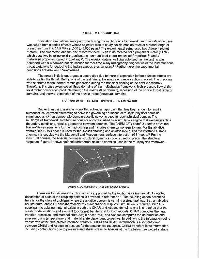
Rather than using a single monolithic solver, an approach that has been shown to result in numerical issues when attempting to solve the governing equations of multiple physical domains simultaneously, 6•7 an appropriate domain-specific solver is used for each physical domain. The multiphysics framework architecture consists of codes linked by a simulation engine that exchanges data (boundary conditions, results, geometry) between domains. The CHEM CFD code8 is used to solve the Navier-Stokes equations for the fluid domain and includes chemical nonequilibrium. For the ablative domain, the CHAR code9 is used for the implicit charring and ablator solver, and the interface surface chemistry is coupled via the Marschall and Maclean gas-surface interaction (GSI) code.1° For the structural domain, the Abaqus nonlinear structural dynamics code is used to predict the structural response. Figure 1 shows notional aerothermal ablation domains used in the multiphysics framework.
Figure 1. Discretization of fluid and ablator domains.
There are four different coupling options supported by the multiphysics framework. A detailed description of each of the coupling options is provided in reference 11. The coupling option described here is for the class of problems where the ablative domain is carrying a structural . load, i.e., an ablative hot structure, and a full aero-thermal-chemical-mechanical response simulation is required. With this coupling, the ablating material exists in both the CHAR and Abaqus domains, and it is required that the mesh (node locations and element topologies) be identical for both models. CHAR computes the heat transfer, recession, and material state (virgin or charred), and Abaqus computes the deformation and stresses using temperature- and material-state-dependent properties. In addition to the information being transferred at the fluid-ablator interface between CHEM and CHAR, information is also transferred between CHEM and Abaqus to account for the mechanical response. CHEM transfers force information, including contributions due to pressure and shear stress, to Abaqus at the fluid-structure wetted surface
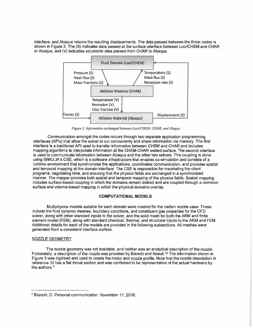
interface, and Abaqus returns the resulting displacements. The data passed between the three codes is shown in Figure 2. The (S) indicates data passed at the surface interface between Loci/CHEM and CHAR or Abaqus, and (V) indicates volumetric data passed from CHAR to Abaqus.
Fluid Domain (Loci/CHEM)
Pressure (S) Temperature (S) Heat Flux (S) Mass flux (S) Mass Fractions (S) Recession rate (SJ
--~~ ........ ~~~~---~~~ ..... Ablative Material (CHAR)
Temperature (VJ Recession (VJ Char fraction (V)
Forces (S) Displacement (S) Ablative Material (Abaqus)
Figure 2. Information exchanged between Loci/CHEM. CHAR. and Abaqus.
Communication amongst the codes occurs through two separate application programming interfaces (APls) that allow the solver to run concurrently and share information via memory. The first interface is a traditional API used to transfer information between CHEM and CHAR and includes mapping algorithms to interpolate information at the CHEM-CHAR wetted surface. The second interface is used to communicate information between Abaqus and the other two solvers. This coupling is done using SIMULIA's CSE, which is a software infrastructure that enables co-simulation and consists of a runtime environment that synchronizes the applications, coordinates communication, and provides spatial and temporal mapping at the domain interface. The CSE is responsible for marshaling the client programs, negotiating time, and ensuring that the physics fields are exchanged in a synchronized manner. The mapper provides both spatial and temporal mapping of the physics fields. Spatial mapping includes surface-based coupling in which the domains remain distinct and are coupled through a common surface and volume-based mapping in which the physical domains overlap.
COMPUTATIONAL MODELS
Multiphysics models suitable for each domain were created for the carbon nozzle case. These include the fluid dynamic meshes, boundary conditions, and constituent gas properties for the CFD solver, along with other standard inputs to the solver, and the solid mesh for both the ARM and finite element model (FEM), along with standard chemical, thermal, and structural inputs to the ARM and FEM. Additional details for each of the models are provided in the following subsections. All meshes were generated from a consistent interface surface.
NOZZLE GEOMETRY
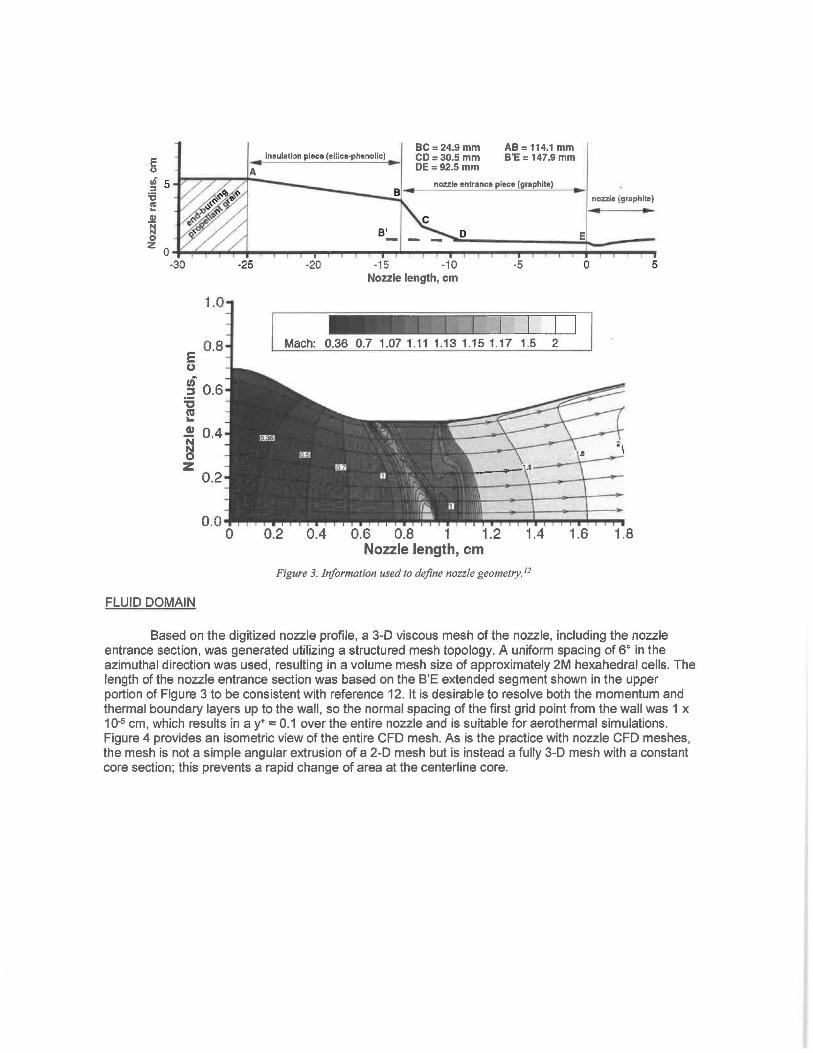
The nozzle geometry was not available, and neither was an analytical description of the nozzle. Fortunately, a description of the nozzle was provided by Bianchi and Nasuti. 12 The information shown in Figure 3 was digitized and used to create the motor and nozzle profile. Note that the nozzle description in reference 12 has a flat throat section and was confirmed to be representative of the actual hardware by the authors.*
* Bianchi, D. Personal communication. November 11, 2016.
E u
~ 5 '6 I'll .. .9! s
insulation piece (silica-phenolic)
A
BC=24.9 mm CD:30.5 mm DE= 92.5 mm
AB= 114.1 mm B'E = 147.9 mm
nozzle entrance piece (graphite)
D E
nozzle (graphite) .. -z o ......... .-"""",.... __ ....,._._.. ........ ~ ............ _. .............. ~ ............ _._...,...'l"""i....,....,. .... """I"' ...
-30 -25 ·20 ·15 ·10 ·5 0 5 Nozzle length, cm
0.8 Mach: 0.36 0.7 1.07 1.11 1.13 1.15 1.17 1.5 2 E (,)
,,; 0.6 :s :s
cu ... G) 0.4
~ z 0.2
0.0 0 0.2 0.4 0.6 0.8 1 1.2 1.4 1.6 1.8
Nozzle length, cm
Figure 3. Information used to define nozzle geometry. 12
FLUID DOMAIN
Based on the digitized nozzle profile, a 3-D viscous mesh of the nozzle, including the nozzle entrance section, was generated utilizing a structured mesh topology. A uniform spacing of 6° in the azimuthal direction was used, resulting in a volume mesh size of approximately 2M hexahedral cells. The length of the nozzle entrance section was based on the B'E extended segment shown in the upper portion of Figure 3 to be consistent with reference 12. It is desirable to resolve both the momentum and thermal boundary layers up to the wall, so the normal spacing of the first grid point from the wall was 1 x 10⁻⁵ cm, which results in a y• = 0.1 over the entire nozzle and is suitable for aerothermal simulations. Figure 4 provides an isometric view of the entire CFO mesh. As is the practice with nozzle CFO meshes, the mesh is not a simple angular extrusion of a 2-D mesh but is instead a fully 3-D mesh with a constant core section; this prevents a rapid change of area at the centerline core.
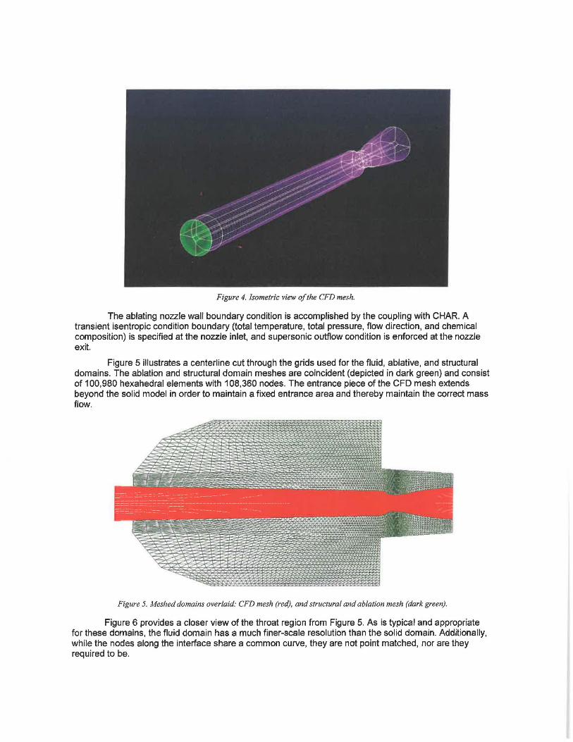
Figure 4. Isometric view of the CFD mesh.
The ablating nozzle wall boundary condition is accomplished by the coupling with CHAR. A transient isentropic condition boundary (total temperature, total pressure, flow direction, and chemical composition) is specified at the nozzle inlet, and supersonic outflow condition is enforced at the nozzle exit.
Figure 5 illustrates a centerline cut through the grids used for the fluid, ablative, and structural domains. The ablation and structural domain meshes are coincident (depicted in dark green) and consist of 100,980 hexahedral elements with 108,360 nodes. The entrance piece of the CFD mesh extends beyond the solid model in order to maintain a fixed entrance area and thereby maintain the correct mass flow.
Figure 5. Meshed domains overlaid: CFD mesh (red), and structural and ablation mesh (dark green).
Figure 6 provides a closer view of the throat region from Figure 5. As is typical and appropriate for these domains, the fluid domain has a much finer-scale resolution than the solid domain. Additionally, while the nodes along the interface share a common curve, they are not point matched, nor are they required to be.
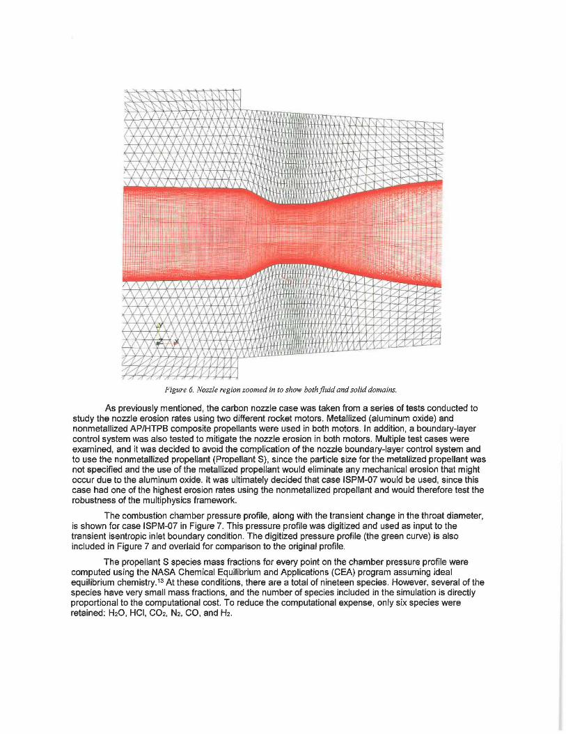
Figure 6. Nozzle region zoomed in to show both fluid and solid domains.
As previously mentioned, the carbon nozzle case was taken from a series of tests conducted to study the nozzle erosion rates using two different rocket motors. Metallized (aluminum oxide) and nonmetallized AP/HTPB composite propellants were used in both motors. In addition, a boundary-layer control system was also tested to mitigate the nozzle erosion in both motors. Multiple test cases were examined, and it was decided to avoid the complication of the nozzle boundary-layer control system and to use the nonmetallized propellant (Propellant S), since the particle size for the metallized propellant was not specified and the use of the metallized propellant would eliminate any mechanical erosion that might occur due to the aluminum oxide. It was ultimately decided that case ISPM-07 would be used, since this case had one of the highest erosion rates using the nonmetallized propellant and would therefore test the robustness of the multiphysics framework.
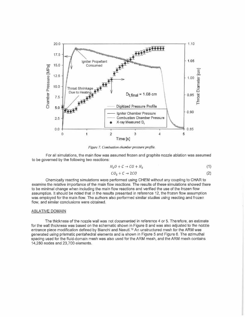
The combustion chamber pressure profile, along with the transient change in the throat diameter, is shown for case ISPM-07 in Figure 7. This pressure profile was digitized and used as input to the transient isentropic inlet boundary condition. The digitized pressure profile (the green curve) is also included in Figure 7 and overlaid for comparison to the original profile.
The propellant S species mass fractions for every point on the chamber pressure profile were computed using the NASA Chemical Equilibrium and Applications (CEA) program assuming ideal equilibrium chemistry. 13 At these conditions, there are a total of nineteen species. However, several of the species have very small mass fractions, and the number of species included in the simulation is directly proportional to the computational cost. To reduce the computational expense, only six species were retained: H20, HCI, C02, N2, CO, and H2.
17.5
~ 15.0
~ ~ 12.5 ::::s I/) I/)
~ 10.0 a. In .0 7.5 E m ~
(.) 5.0
2.5
Igniter Propellant Consumed
Throat shrin~age IH!r Due to Healln D - 1 08 cm
t,final - ·
~_If_I Digmzed Pressure Profile
-- Igniter Chamber Pressure -- Combustion Chamber Pressure
• X-ray Measured 01
1.05
'E .!:?.
1.00 Ci> 'a) E m i:5
0.95 ~
0.90
~ I-
0.0 +-------.-----=:::;========:;:========:::;=:::::::'...._~~ 0.85 0 2 3 4 5
Time [s]
Figure 7. Combustion chamber pressure profile.
For all simulations, the main flow was assumed frozen and graphite nozzle ablation was assumed to be governed by the following two reactions:
H2 0 + C ~ CO + H2
C02 +C ~ ZCO
(1)
(2)
Chemically reacting simulations were performed using CHEM without any coupling to CHAR to examine the relative importance of the main flow reactions. The results of these simulations showed there to be minimal change when including the main flow reactions and verified the use of the frozen flow assumption. It should be noted that in the results presented in reference 12, the frozen flow assumption was employed for the main flow. The authors also performed similar studies using reacting and frozen flow, and similar conclusions were obtained.
ABLATIVE DOMAIN
The thickness of the nozzle wall was not documented in reference 4 or 5. Therefore, an estimate for the wall thickness was based on the schematic shown in Figure 8 and was also adjusted to the nozzle entrance piece modification defined by Bianchi and Nasuti.12 An unstructured mesh for the ARM was generated using prismatic pentahedral elements and is shown in Figure 5 and Figure 6. The azimuthal spacing used for the fluid-domain mesh was also used for the ARM mesh, and the ARM mesh contains 14,280 nodes and 23,700 elements.
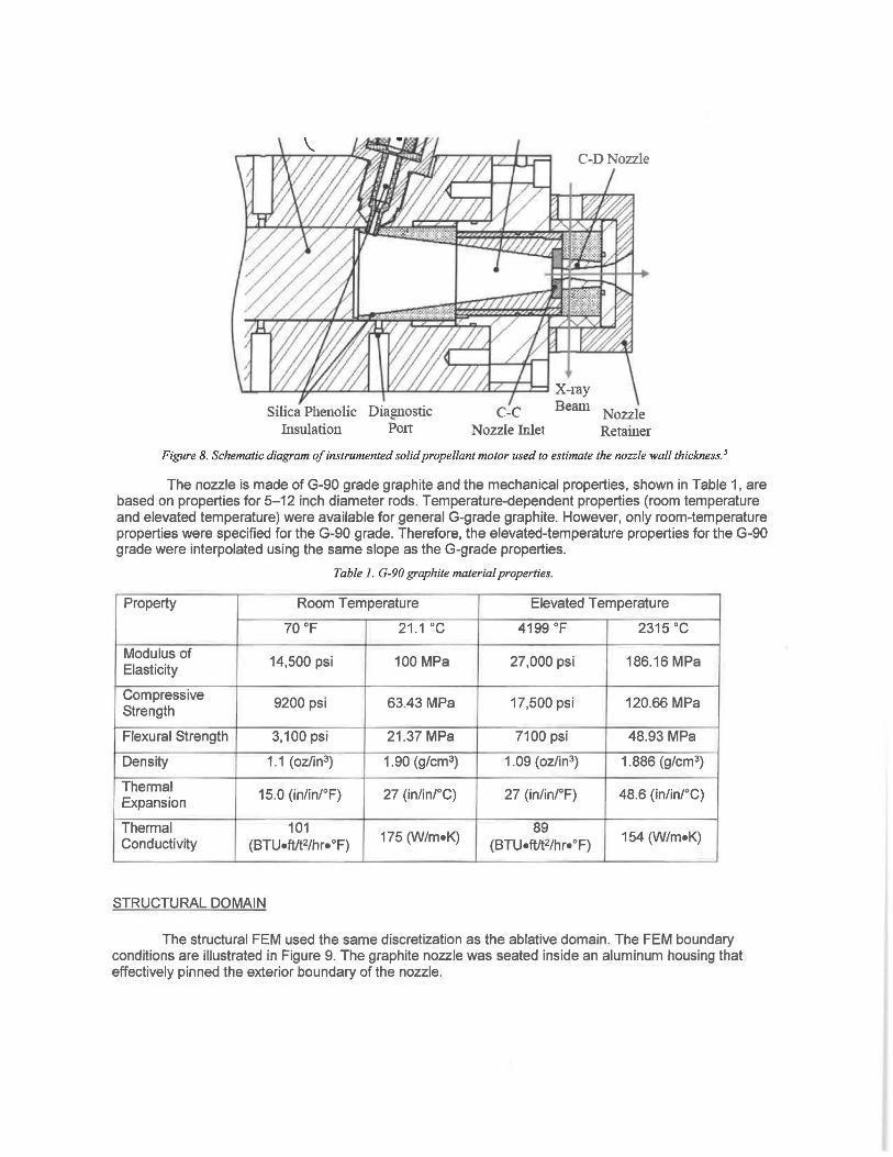
U..-1LLJ.U (LtL1.JU(L.LL'-LL.'-'1.(..L.d::z-::/:.=8 X-ray
Silica Phenolic Diagnostic C-C Beam Nozzle hlsulation Pott Nozzle Inlet Retainer
Figure 8. Schematic diagram of instrumented solid propellant motor used to estimate the nozzle wall thickness. 5
The nozzle is made of G-90 grade graphite and the mechanical properties, shown in Table 1, are based on properties for 5-12 inch diameter rods. Temperature-dependent properties (room temperature and elevated temperature) were available for general G-grade graphite. However, only room-temperature properties were specified for the G-90 grade. Therefore, the elevated-temperature properties for the G-90 grade were interpolated using the same slope as the G-grade properties.
Table 1. G-90 graphite material properties.
Property Room Temperature Elevated Temperature
70 °F 21.1 ·c 4199 °F 2315 ·c Modulus of
14,500 psi 100 MPa 27,000 psi 186.16 MPa Elasticity
Compressive 9200 psi 63.43 MPa 17,500 psi 120.66 MPa
Strength
Flexural Strength 3,100 psi 21 .37 MPa 7100 psi 48.93 MPa
Density 1.1 (oz/in3) 1.90 (g/cm3) 1.09 (oz/in3) 1.886 (g/cm3)
Thermal 15.0 (in/in/°F) 27 (in/in/°C) 27 (in/in/°F) 48.6 (in/in/°C) Expansion
Thermal 101 175 (W/m•K)
89 154 (W/m•K) Conductivity (BTU•fVt2/hr• °F) (8TU•ftft2/hr•°F)
STRUCTURAL DOMAIN
The structural FEM used the same discretization as the ablative domain. The FEM boundary conditions are illustrated in Figure 9. The graphite nozzle was seated inside an aluminum housing that effectively pinned the exterior boundary of the nozzle.
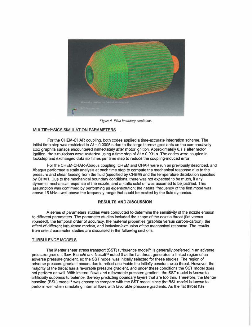
Figure 9. FEM boundary conditions.
MUL TIPHYSICS SIMULATION PARAMETERS
For the CHEM-CHAR coupling, both codes applied a time-accurate integration scheme. The initial time step was restricted to ll.t = 0.0005 s due to the large thermal gradients on the comparatively cool graphite surface encountered immediately after motor ignition. Approximately 0.1 s after motor ignition, the simulations were restarted using a time step of ll.t = 0.001 s. The codes were coupled in lockstep and exchanged data six times per time step to reduce the coupling-induced error.
For the CHEM-CHAR-Abaqus coupling, CHEM and CHAR were run as previously described, and Abaqus performed a static analysis at each time step to compute the mechanical response due to the pressure and shear loading from the fluid (specified by CHEM) and the temperature distribution specified by CHAR. Due to the mechanical boundary conditions, there was not expected to be much, if any, dynamic mechanical response of the nozzle, and a static solution was assumed to be justified. This assumption was confirmed by performing an eigensolution; the natural frequency of the first mode was above 15 kHz-well above the frequency range that could be excited by the fluid dynamics.
RESULTS AND DISCUSSION
A series of parameters studies were conducted to determine the sensitivity of the nozzle erosion to different parameters. The parameter studies included the shape of the nozzle throat (flat versus rounded), the temporal order of accuracy, the material properties (graphite versus carbon-carbon), the effect of different turbulence models, and inclusion/exclusion of the mechanical response. The results from select parameter studies are discussed in the following sections.
TURBULENCE MODELS
The Menter shear stress transport (SST) turbulence model14 is generally preferred in an adverse pressure gradient flow. Bianchi and Nasuti12 noted that the flat throat generates a limited region of an adverse pressure gradient, so the SST model was initially selected for these studies. The region of adverse pressure gradient occurs due to reflections inside the initially constant-area throat. However, the majority of the throat has a favorable pressure gradient, and under these conditions the SST model does not perform as well. With internal flows and a favorable pressure gradient, the SST model is known to artificially suppress turbulence, thereby predicting boundary layers that are too thin. Therefore, the Menter baseline (BSL) model1 4 was chosen to compare with the SST model since the BSL model is known to perform well when simulating internal flows with favorable pressure gradients. As the flat throat has
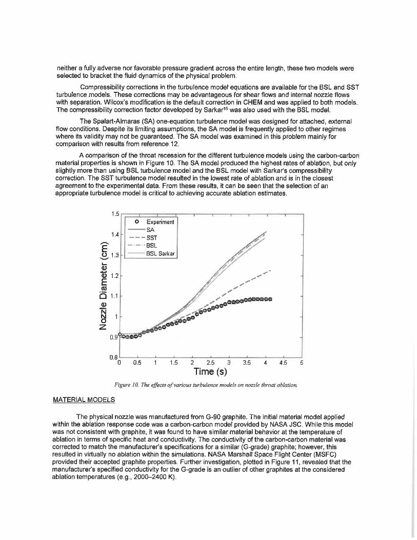
neither a fully adverse nor favorable pressure gradient across the entire length, these two models were selected to bracket the fluid dynamics of the physical problem.
Compressibility corrections in the turbulence model equations are available for the BSL and SST turbulence models. These corrections may be advantageous for shear flows and internal nozzle flows with separation. Wilcox's modification is the default correction in CHEM and was applied to both models. The compressibility correction factor developed by Sarkar15 was also used with the BSL model.
The Spalart-Almaras (SA) one-equation turbulence model was designed for attached, external flow conditions. Despite its limiting assumptions, the SA model is frequently applied to other regimes where its validity may not be guaranteed. The SA model was examined in this problem mainly for comparison with results from reference 12.
A comparison of the throat recession for the different turbulence models using the carbon-carbon material properties is shown in Figure 10. The SA model produced the highest rates of ablation, but only slightly more than using BSL turbulence model and the BSL model with Sarkar's compressibility correction. The SST turbulence model resulted in the lowest rate of ablation and is in the closest agreement to the experimental data. From these results, it can be seen that the selection of an appropriate turbulence model is critical to achieving accurate ablation estimates.
1.4 -E ~ 1.3 L... (I) ...... (I) 1.2 E Ol Q 1.1 (l)
~ z
0.9
O Experiment - SA --- SST -·-·· BSL --BSL Sarkar
o .s ~-~--'--~-~--~-_._~_._ _ __. __ .____. 0 0.5 1.5 2 2.5 3 3.5 4 4.5 5
Time (s) Figure I 0. The effects of various turbulence models on nozzle throat ablation.
MATERIAL MODELS
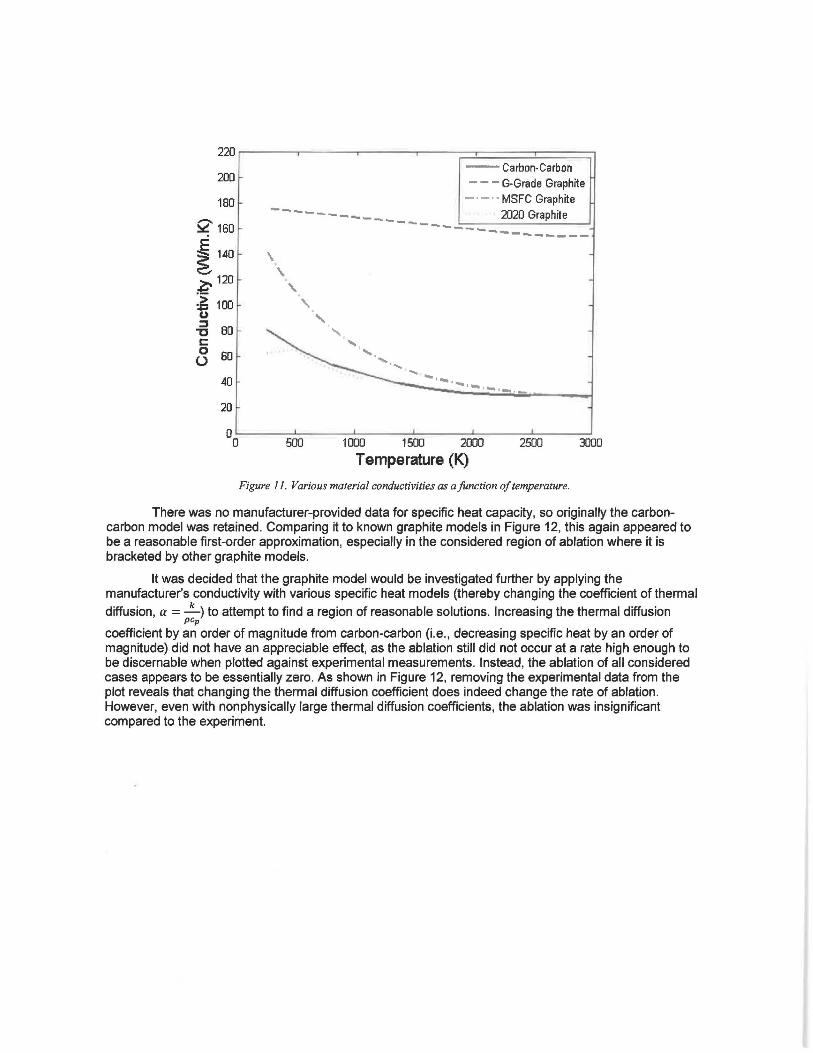
The physical nozzle was manufactured from G-90 graphite. The initial material model applied within the ablation response code was a carbon-carbon model provided by NASA JSC. While this model was not consistent with graphite, it was found to have similar material behavior at the temperature of ablation in terms of specific heat and conductivity. The conductivity of the carbon-carbon material was corrected to match the manufacturer's specifications for a similar (G-grade) graphite; however, this resulted in virtually no ablation within the simulations. NASA Marshall Space Flight Center (MSFC) provided their accepted graphite properties. Further investigation, plotted in Figure 11, revealed that the manufacturer's specified conductivity for the G-grade is an outlier of other graphites at the considered ablation temperatures (e.g., 2000-2400 K).
220 .----~~~~~~--..-~~~..--~~~~~~--.-~~----.
200
180
e 160
i 140
:;:- 120
~ 100 (.)
-6 BO s:: 0 60 0
40
20
--Carbon-Carbon
- - - G-Grade Graphite
- · - · • MSFC Graphite
2020 Graphite ------ ..... ""119-
_____
\
' ' ' '
500
- ..... __ _ ---------
·--1-,--.,,_,.,_
1000 1500 2000 2500 3000
Temperature (K)
Figure 11. Various material conductivities as a function of temperature.
There was no manufacturer-provided data for specific heat capacity, so originally the carboncarbon model was retained. Comparing it to known graphite models in Figure 12, this again appeared to be a reasonable first-order approximation, especially in the considered region of ablation where it is bracketed by other graphite models.
It was decided that the graphite model would be investigated further by applying the manufacturer's conductivity with various specific heat models (thereby changing the coefficient of thermal
diffusion, a = ...!:...) to attempt to find a region of reasonable solutions. Increasing the thermal diffusion pep
coefficient by an order of magnitude from carbon-carbon (i.e., decreasing specific heat by an order of magnitude) did not have an appreciable effect, as the ablation still did not occur at a rate high enough to be discernable when plotted against experimental measurements. Instead, the ablation of all considered cases appears to be essentially zero. As shown in Figure 12, removing the experimental data from the plot reveals that changing the thermal diffusion coefficient does indeed change the rate of ablation. However, even with nonphysically large thermal diffusion coefficients, the ablation was insignificant compared to the experiment.

0.9185 .---.---....----.--- -.------.-----.----.--.-----.
- 0.918 E 0 -L... Cl) a; 0.9175
E m i5 0.917 Q)
~ z 0.9165
--Alpha=50e-5 m2/s
- · - · • Alpha=10.1 e-5 m2/s
- - - Alpha=5.5e-5 m2/s
Alpha=3.7e-5 m2/s
0.5 1.5 2 2.5 3 3.5 4 4.5 5
Time (s) Figure I 2. The effects of thermal diffesion coefficient on ablation.
Due to the uncertainty in the material properties, a minimum of two models were required to bound the measured material data. The conductivity of carbon-carbon and the NASA MSFC graphite model are similar over the 1500-3000 K temperature range, but there are significant discrepancies in the lower temperature range. The carbon-carbon model closely matches the graphite 2020 conductivity in the lower temperature range, but it was unclear whether the nuclear-grade graphite is applicable to this class of problems, so the graphite 2020 model was not considered for use. Because the G-grade graphite model is an outlier with respect to conductivity and was unable to predict any appreciable recession, the G-grade graphite model was not employed in the final simulations. Based on the above findings, it was decided that the material models applied within the simulations would be limited to the original carboncarbon model and the model built with NASA MSFC graphite parameters. Therefore, two final models were considered in this effort: a carbon-carbon model and the MSFC graphite model.
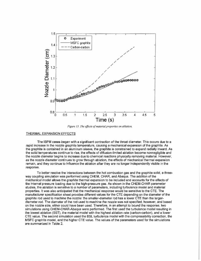
A comparison of the throat recession using different material models is shown in Figure 13. For material model parameter studies, the BSL turbulence model with Sarkar's compressibility correction was used along with the flattened throat profile. Three different sets of material properties were examined: carbon-carbon, graphite using data provided by the MSFC Propulsion Systems Department, and graphite properties provided by the manufacturer. As discussed previously, the graphite properties provided by the manufacturer were suspect, as they had atypically high conductivity that resulted in no appreciable ablation, thus they are not included here. The carbon-carbon, which had lower conductivity and specific heat values than the MSFC graphite, resulted in the highest amounts of ablation.
1.4 -E ~ 1.3 L.. (I)
Q) 1.2 E as b 1.1 (I)
N
~ z 0.9
O Experiment --MSFC graphite - - - Carbon-carbon
o.s ~~~~~~~~~~~~~~~~~~~~~~~~~
0 0.5 1.5 2 2.5 3 3.5 4 4.5 5
Time (s) Figure 13. The effects of material prop erties on ablation.
THERMAL EXPANSION EFFECTS
The ISPM cases began with a significant contraction of the throat diameter. This occurs due to a rapid increase in the nozzle graphite temperature, causing a mechanical expansion of the graphite. As the graphite is contained in an aluminum sleeve, the graphite is constrained to expand radially inward. As the solid temperatures continue to rise, the effects of diffusion-limited ablation become nonnegligible and the nozzle diameter begins to increase due to chemical reactions physically removing material. However, as the nozzle diameter continues to grow through ablation, the effects of mechanical thermal expansion remain, and they continue to influence the ablation after they are no longer independently visible in the response.
To better resolve the interactions between the hot combustion gas and the graphite solid, a threeway coupling simulation was performed using CHEM, CHAR, and Abaqus. The addition of the mechanical model allows the graphite thermal expansion to be included and accounts for the effects of the internal pressure loading due to the high-pressure gas. As shown in the CHEM-CHAR parameter studies, the ablation is sensitive to a number of parameters, including turbulence model and material properties. It was also anticipated that the mechanical response would be sensitive to the CTE. The manufacturer specification sheet provides different values for the CTE depending on the diameter of the graphite rod used to machine the nozzle: the smaller-diameter rod has a lower CTE than the largerdiameter rod. The diameter of the rod used to machine the nozzle was not specified, however, and based on the nozzle size, either could have been used. Therefore, in an attempt to bound the response, two simulations using CHEM-CHAR-Abaqus were performed. The first used the turbulence model resulting in the lowest ablation (SST), the material model with the highest ablation rate (carbon-carbon), and a lower CTE value. The second simulation used the BSL turbulence model with the compressibility correction, the MSFC graphite model, and the higher CTE value. The values of the parameters used for the simulations are summarized in Table 2.
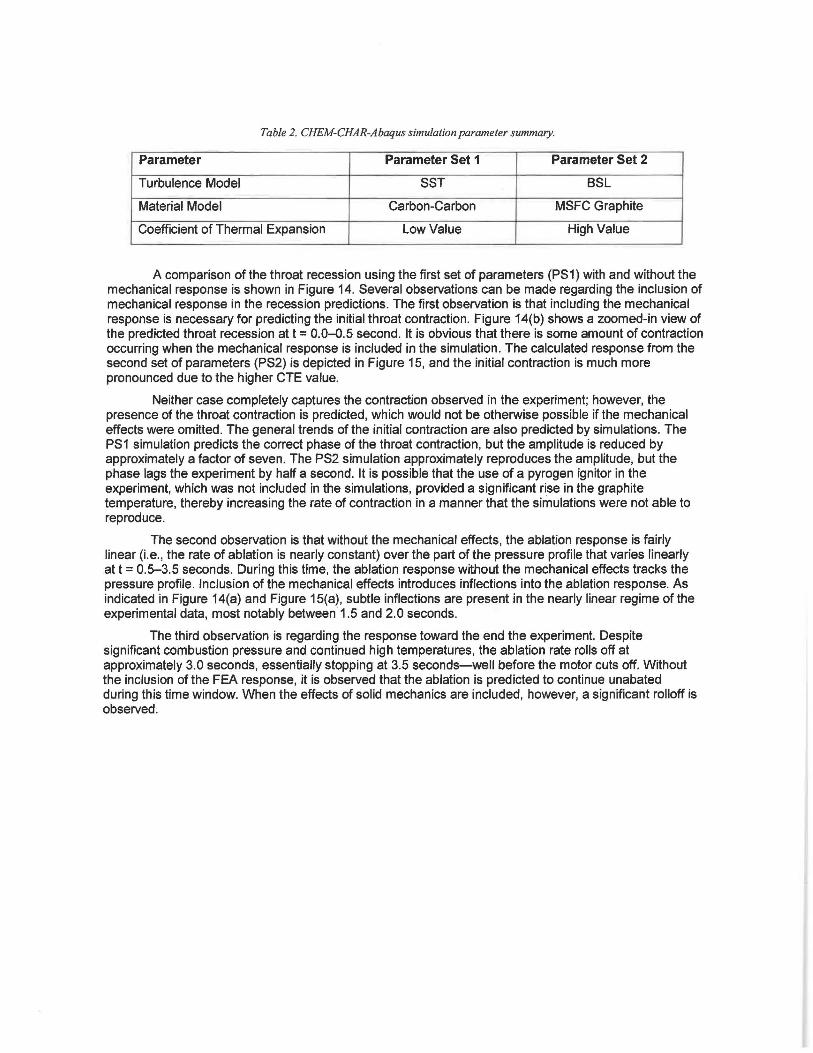
Table 2. CHEM-CHAR-Abaqus simulation parameter summary.
Parameter Parameter Set 1 Parameter Set 2
Turbulence Model SST BSL
Material Model Carbon-Carbon MSFC Graphite
Coefficient of Thermal Expansion Low Value High Value
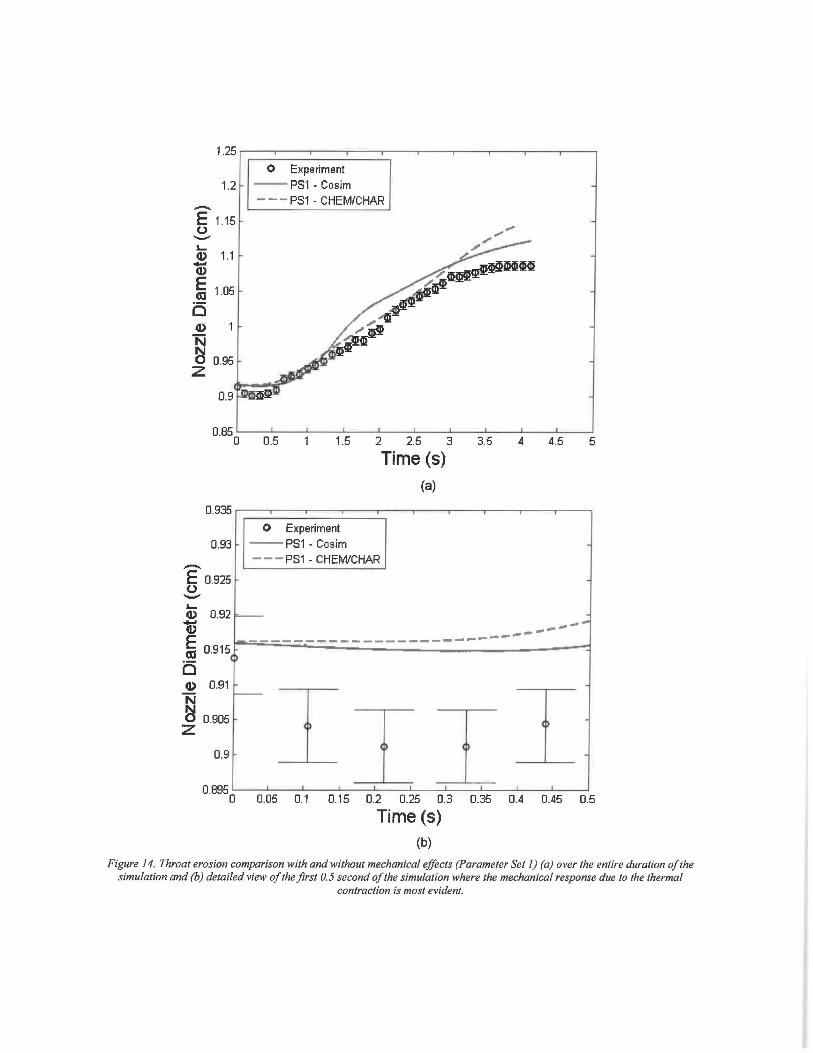
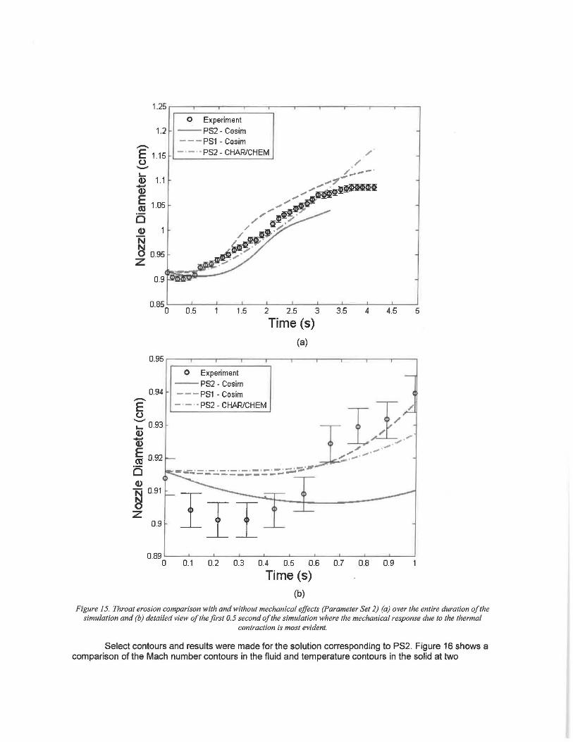
A comparison of the throat recession using the first set of parameters (PS1) with and without the mechanical response is shown in Figure 14. Several observations can be made regarding the inclusion of mechanical response in the recession predictions. The first observation is that including the mechanical response is necessary for predicting the initial throat contraction. Figure 14(b) shows a zoomed-in view of the predicted throat recession at t = 0.0-0.5 second. It is obvious that there is some amount of contraction occurring when the mechanical response is included in the simulation. The calculated response from the second set of parameters (PS2) is depicted in Figure 15, and the initial contraction is much more pronounced due to the higher CTE value.
Neither case completely captures the contraction observed in the experiment; however, the presence of the throat contraction is predicted, which would not be otherwise possible if the mechanical effects were omitted. The general trends of the initial contraction are also predicted by simulations. The PS1 simulation predicts the correct phase of the throat contraction, but the amplitude is reduced by approximately a factor of seven. The PS2 simulation approximately reproduces the amplitude, but the phase lags the experiment by half a second. It is possible that the use of a pyrogen igniter in the experiment, which was not included in the simulations, provided a significant rise in the graphite temperature, thereby increasing the rate of contraction in a manner that the simulations were not able to reproduce.
The second observation is that without the mechanical effects, the ablation response is fairly linear (i.e., the rate of ablation is nearly constant) over the part of the pressure profile that varies linearly at t = 0.5-3.5 seconds. During this time, the ablation response without the mechanical effects tracks the pressure profile. Inclusion of the mechanical effects introduces inflections into the ablation response. As indicated in Figure 14(a) and Figure 15(a), subtle inflections are present in the nearly linear regime of the experimental data, most notably between 1.5 and 2.0 seconds.
The third observation is regarding the response toward the end the experiment. Despite significant combustion pressure and continued high temperatures, the ablation rate rolls off at approximately 3.0 seconds, essentially stopping at 3.5 seconds-well before the motor cuts off. Without the inclusion of the FEA response, it is observed that the ablation is predicted to continue unabated during this time window. When the effects of solid mechanics are included, however, a significant rolloff is observed.
1.25 ~--.-.-~--~--.----.---.,~-~----.------.~-----.
0 Experiment 1.2 --PS1 - Cosim
- - - PS1 - CHEM/CHAR -E 1.1s 0 -L. Q) 1.1 -Q)
E 1.05 Gl 0 (I)
N ~ 0.95 z
0.9
0.85 0 0.5 1.5 2 2.5 3 3.5 4 4.5 5
Time (s) {a)
0.935 ~-~-~-~-----.~-~-~----.------.--~-
0.93
-E o.925 0 -L. Q) 0.92
0 Experiment --PS1 - Cosim - - - PS1 - CHEM/CHAR
v ~~~~ .,.._.- ... ~ 0.915 r--=-::..:-=..:-:;.::,-=-:..::-:.:-::.:-:.:-::.=.-.::-:.:-:.:-:.:-:.:-::-=-.:-:.::-:.:-_-______ -:1 b Q) 0.91
~ 0.905 z 0.9
0.8950 0.05 0.1 0.15 0.2 0.25 0.3 0.35 0.4 0.45 0.5
Time (s) {b)
Figure 14. Throat erosion comparison with and without mechanical effects (Parameter Set 1) (a) over the entire duration of the simulation and (b) detailed view of the first 0.5 second of the simulation where the mechanical response due to the thermal
contraction is most evident.
1.2
-E 1.15 u -L.. CD 1.1 v E (tJ 1.05
0 CD
"N ~ 0.95 z
0.9
0.85 0
O Experiment
--PS2 - Cosim ---PS1- Cosim
- · - · • P82 - CHAR/CHEM
0.5 1.5 2 2.5 3
Time (s) (a)
3.5
/ /
4 4.5 5
0.95 ..---,---~--..----.---~--..----.---~-----.-~
0.94 -E u -.... 0.93 CD v i 0.92
Ci CD ~ 0.91
z 0.9
0 Experiment
--PS2 - Cosim ---PS1 - Cosim
- · - · • P82 - CHAR/CHEM
Irr 0.89 L---'-----L--...._ _ _,_ _ _ ..__ _ _._ _ __..__ _ _,_ _ __. _ ___,
0 0.1 0.2 0.3 0.4 0.5 0.6 0.7 0.8 0.9
Time (s) (b)
Figure I 5. Throat erosion comparison with and without mechanical effects (Parameter Set 2) (a) over the entire duration of the simulation and (b} detailed view of the first 0.5 second of the simulation where the mechanical response due to the thermal
contraction is most evident.
Select contours and results were made for the solution corresponding to PS2. Figure 16 shows a comparison of the Mach number contours in the fluid and temperature contours in the solid at two
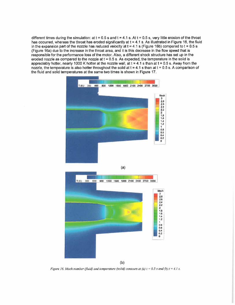
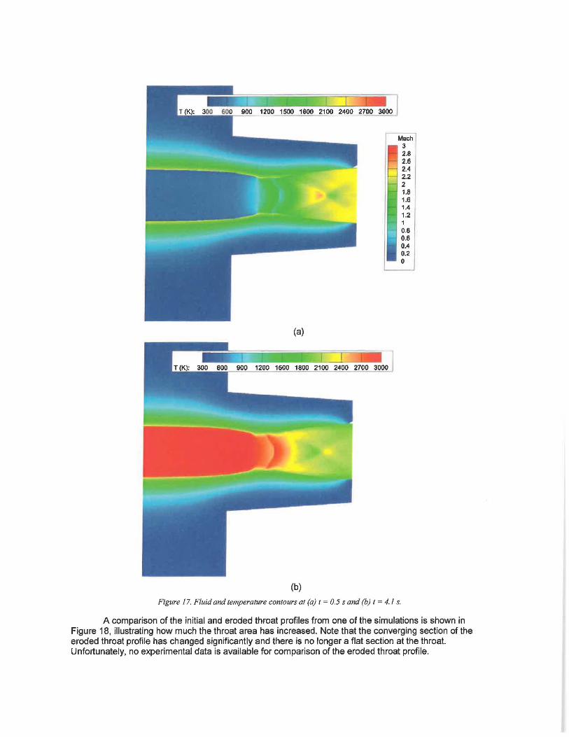
different times during the simulation: at t = 0.5 sand t = 4.1 s. At t = 0.5 s, very little erosion of the throat has occurred, whereas the throat has eroded significantly at t = 4.1 s. As illustrated in Figure 16, the fluid in the expansion part of the nozzle has reduced velocity at t = 4.1 s (Figure 1 Sb) compared tot = 0.5 s (Figure 16a) due to the increase in the throat area, and it is this decrease in the flow speed that is responsible for the performance loss of the motor. Also, a different shock structure has set up in the eroded nozzle as compared to the nozzle at t = 0.5 s. As expected, the temperature in the solid is appreciably hotter, nearly 1000 K hotter at the nozzle wall, at t = 4.1 s than at t = 0.5 s. Away from the nozzle, the temperature is also hotter throughout the solid at t = 4.1 s than at t = 0.5 s. A comparison of the fluid and solid temperatures at the same two times is shown in Figure 17.
(a)
(b)
Math 3 2 .8 2.6 2.4 2.2 2 1.8 1.6 1.4 1.2 1 0.8 0.6 0.4 0.2 0
Mach 3 2.8 2 .6 2.4 22 2 1.8 1.6 1.4 12 1 0.8 0 .6 0 .4 02 0
Figure 16. Mach number (fluid) and temperature (solid) contours at (a) I = 0.5 sand (b) t = 4.1 s.
(a)
(b)
Figure 17. Fluid and temperature contours at (a) t = 0.5 sand (b) I = 4.1 s.
1 0.8 0.6 0.4 0.2 0
A comparison of the initial and eroded throat profiles from one of the simulations is shown in Figure 18, illustrating how much the throat area has increased. Note that the converging section of the eroded throat profile has changed significantly and there is no longer a flat section at the throat. Unfortunately, no experimental data is available for comparison of the eroded throat profile.
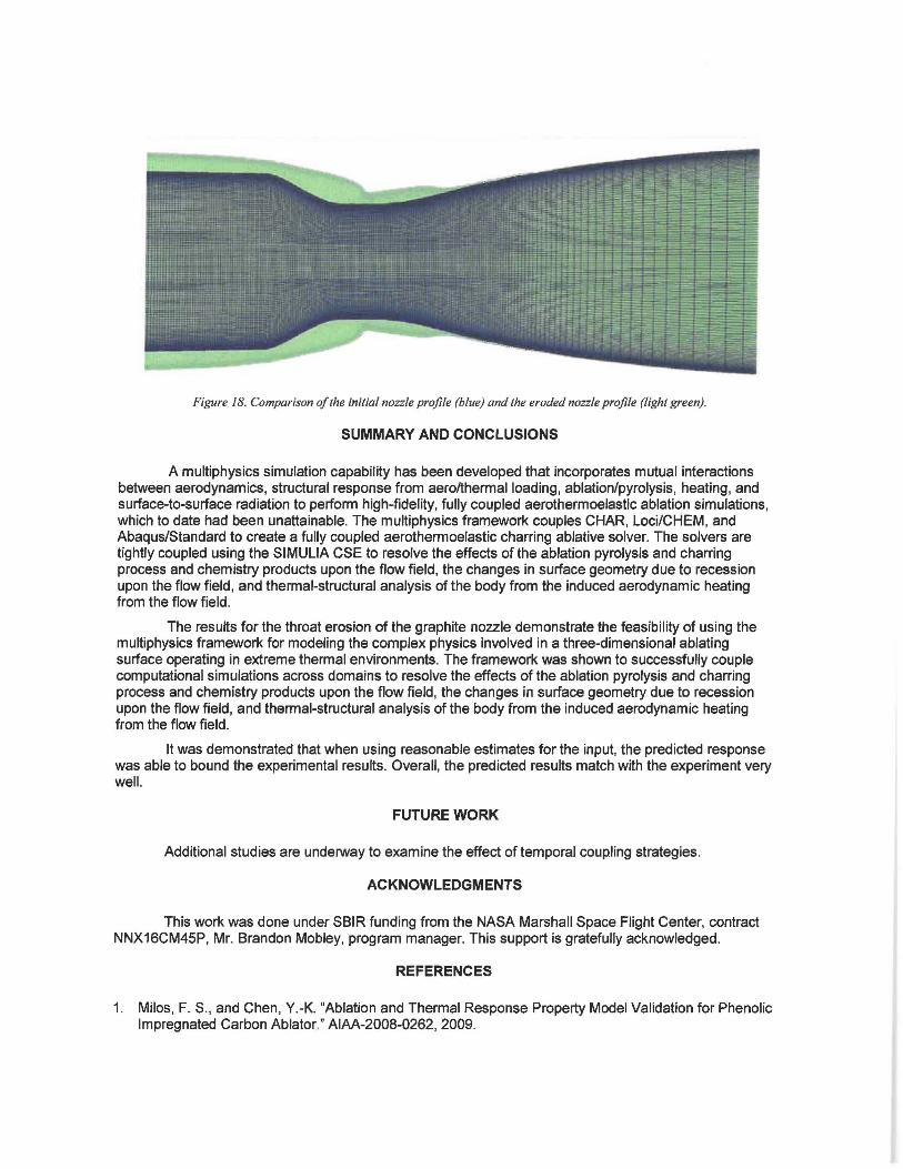
Figure 18. Comparison of the initial nozzle profile (blue) and the eroded nozzle profile (light green).
SUMMARY AND CONCLUSIONS
A multiphysics simulation capability has been developed that incorporates mutual interactions between aerodynamics, structural response from aero/thermal loading, ablation/pyrolysis, heating, and surface-to-surface radiation to perform high-fidelity, fully coupled aerothermoelastic ablation simulations, which to date had been unattainable. The multiphysics framework couples CHAR, Loci/CHEM, and Abaqus/Standard to create a fully coupled aerothermoelastic charring ablative solver. The solvers are tightly coupled using the SIMULIA CSE to resolve the effects of the ablation pyrolysis and charring process and chemistry products upon the flow field, the changes in surface geometry due to recession upon the flow field, and thermal-structural analysis of the body from the induced aerodynamic heating from the flow field.
The results for the throat erosion of the graphite nozzle demonstrate the feasibility of using the multiphysics framework for modeling the complex physics involved in a three-dimensional ablating surface operating in extreme thermal environments. The framework was shown to successfully couple computational simulations across domains to resolve the effects of the ablation pyrolysis and charring process and chemistry products upon the flow field, the changes in surface geometry due to recession upon the flow field, and thermal-structural analysis of the body from the induced aerodynamic heating from the flow field.
It was demonstrated that when using reasonable estimates for the input, the predicted response was able to bound the experimental results. Overall, the predicted results match with the experiment very well.
FUTURE WORK
Additional studies are underway to examine the effect of temporal coupling strategies.
ACKNOWLEDGMENTS
This work was done under SBIR funding from the NASA Marshall Space Flight Center, contract NNX16CM45P, Mr. Brandon Mobley, program manager. This support is gratefully acknowledged.
REFERENCES
1. Milos, F. S., and Chen, Y.-K. "Ablation and Thermal Response Property Model Validation for Phenolic Impregnated Carbon Ablator." AIAA-2008-0262, 2009.
2. Chen, Y.-K., et al. "Graphite Ablation and Thermal Response Simulation Under Arc-Jet Flow Conditions." AIAA-2003-4042, 2003.
3. Nompelis, I. , Candler, G., and Conti, R. "A Parallel Implicit CFO Code for the Simulation of Ablating Re-Entry Vehicles." AIAA-2009-1562. 2009.
4. Evans, B. "Nozzle Erosion Characterization and Minimization for High-Pressure Rocket Motor Applications." Ph.D. dissertation, Pennsylvania State University. 2010.
5. Evans, B., Kuo, K. K., Boyd, E., and Cortopassi, A. C. "Comparison of Nozzle Throat Erosion Behavior in a Solid-Propellant Rocket Motor and a Simulator.· AIAA-2009-5421, 2009.
6. Guruswamy, G.P. "Coupled Finite-Difference/Finite Element Approach for Wing-Body Aeroelasticity." AIAA-1992-4680-CP. 1992.
7. Guruswamy, G.P., and Byun, C. "Fluid-Structural Interactions Using the Navier-Stokes Flow Equations Coupled with Shell Finite Element Structures.· AIAA-1993-3087. 1993.
8. Luke, E. "On Robust and Accurate Arbitrary Polytope CFO Solvers (Invited)." AIAA 2007-3956. 2007. 9. Amar, A., Calvert, N., and Kirk, B. "Development and Verification of the Charring Ablating Thermal
Protection Implicit System Solver." AIAA-2011-0144. 2011. 10. Marschall, J., and Maclean, M. "Finite-Rate Surface Chemistry Model, I.• AIAA-2011-3783. 2011. 11 . Blades, E.L., Reveles, N. D., Nucci, M., and Miskovish, R. S. "A Computational Framework for the
Analysis of an Aero-Thermochemical-Elastic Eroding Nozzle." SIMULIA Global User Conference. 2017.
12. Bianchi, D., and Nasuti, F. "Navier-Stokes Simulation of a Graphite Nozzle Erosion at Different Pressure Conditions." A/AA Journal, Vol. 53, No. 2, pp. 356-366 (2014).
13. Gordon, S., and McBride, B. J. "Computer Program for Calculation of Complex Chemical Equilibrium Compositions and Applications." NASA RP-1311 . 1994.
14. Menter, F. F. "Two-Equation Eddy-Viscosity Turbulence Models for Engineering Applications." A/AA Journal, Vol. 32, No. 8, pp. 1598-1605 (1994).
15. Sarkar, S., and Lakshmanan, B. "Application of a Reynolds Stress Turbulence Model to the Compressible Shear Layer." A/AA Journal, Vol. 29, No. 5, pp. 743-749 (1991).
Related Documents