LOCKHEED M A R T I N_ :;_ Friction Stir Process Mapping Methodology Gerry Bjorkman Alex Kooney Lockheed Martin Space Systems Company Carolyn Russell Marshall Space Flight Center m ('3 o (o p..= ¢..v o ,o 0 0 I 0 C_ O0 https://ntrs.nasa.gov/search.jsp?R=20020094338 2020-06-22T03:56:03+00:00Z

Welcome message from author
This document is posted to help you gain knowledge. Please leave a comment to let me know what you think about it! Share it to your friends and learn new things together.
Transcript
LOCKHEED M A R T I N_ :;_
Friction Stir Process
Mapping Methodology
Gerry Bjorkman
Alex Kooney
Lockheed Martin Space Systems Company
Carolyn Russell
Marshall Space Flight Center
m
('3
o
(o
p..=
¢..vo,o
0
0I
0C_
O0
https://ntrs.nasa.gov/search.jsp?R=20020094338 2020-06-22T03:56:03+00:00Z
Process Overview ,°,,,,,,
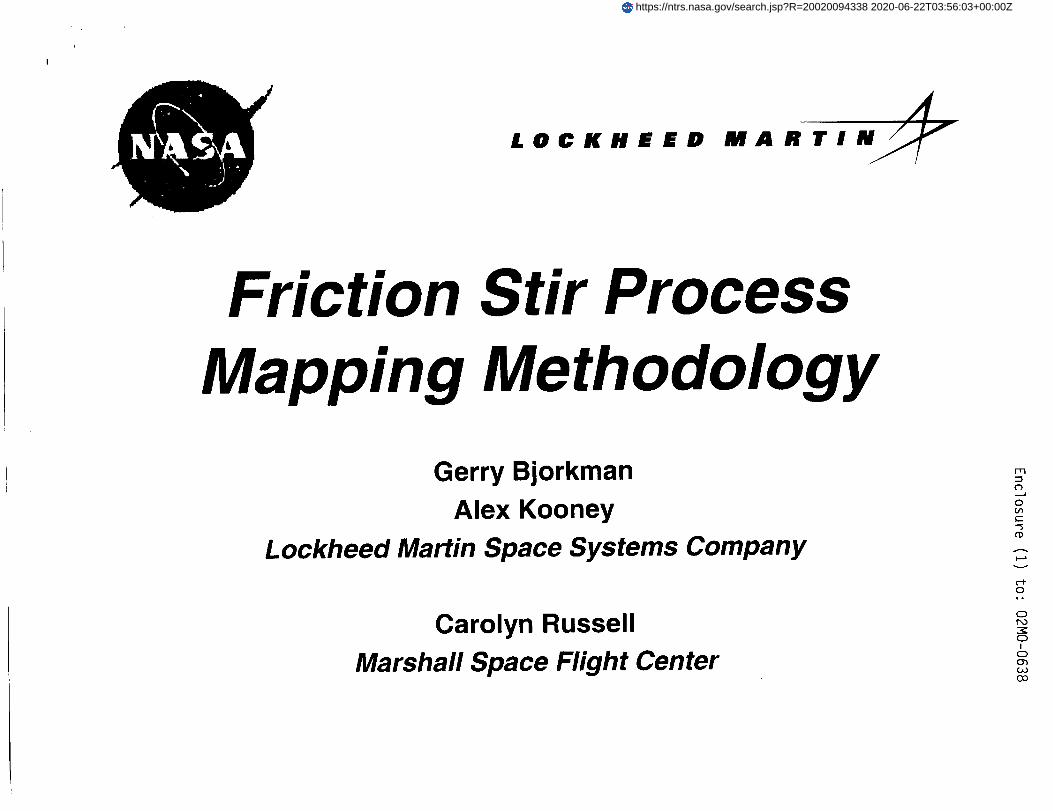
Friction Stir Welding (FSW)- FSW is a solid-state process using
a rotating tool with a shoulder anda projecting pin.
- The pin tool is rotated and plungedinto the joint until the shouldercontacts the top surface.
- The frictional heating between thepin tool and the joint plasticizes thematerial in the local region nearthe pin.
- The material at the weld centerline
is joined through a combination offorging processes that occurs inthe local region of the pin tool.
- Three significant parameters:spindle speed, travel speed,plunge load or plunge position
Heel
Plunge
Travel
Rotation
Penetration
Ligament
9/18/2002 Friction Stir Process Mapping Methodology 2
FSW Process L@©KllEED MARTIN_
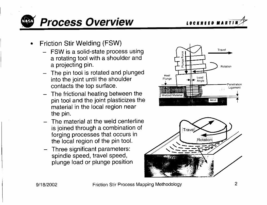
A process map summarizes the weld process performance for a given
pin tool geometry and joint configuration.
Targeting a consistent penetration ligament, the process is simplified
into two parameters: travel speed and rotation speed.
Other parameters, such as plunge force, traverse force, weld nugget
geometry, NDE response, and mechanical properties are assumed to
be dependent variables.
I . |#.
4,4 ,j r..,,,
i I/ i _
wP • IP"
YELLOW: Unusual flow
patterns, unstable position andprocess loads, excessive flash,poor mechanical properties
GREEN: Symmetric flowpatterns, stable position andprocess loads, good strength
RED: NDE rejections,volumetric defects, poorstrength, excessive processloads
IPM
Friction Stir Process Mapping Methodology9/18/2002 3
FSW Process LO¢I(ilEED HARTIN_
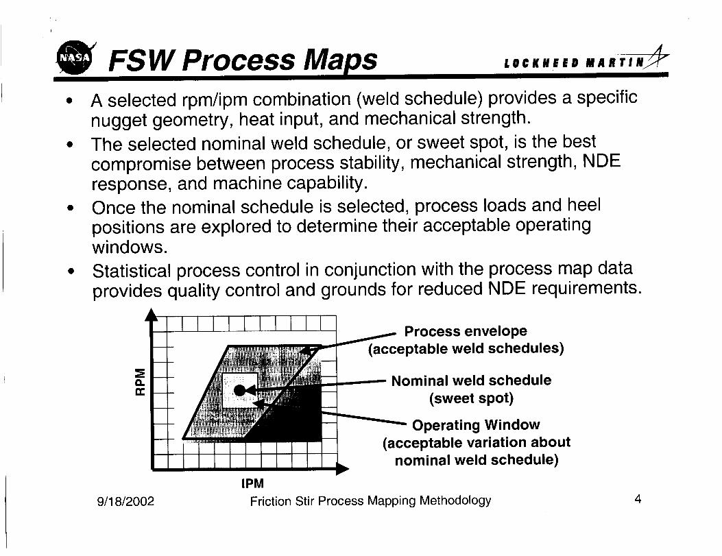
A selected rpm/ipm combination (weld schedule) provides a specificnugget geometry, heat input, and mechanical strength.The selected nominal weld schedule, or sweet spot, is the bestcompromise between process stability, mechanical strength, NDEresponse, and machine capability.Once the nominal schedule is selected, process loads and heelpositions are explored to determine their acceptable operatingwindows.
Statistical process control in conjunction with the process map dataprovides quality control and grounds for reduced NDE requirements.
a.
Process envelope
(acceptable weld schedules)
Nominal weld schedule
(sweet spot)
Operating Window(acceptable variation about
nominal weld schedule)
IPM
Friction Stir Process Mapping Methodology9/18/2002 4
(_ FSW Process L@¢KHEED MARTIN_
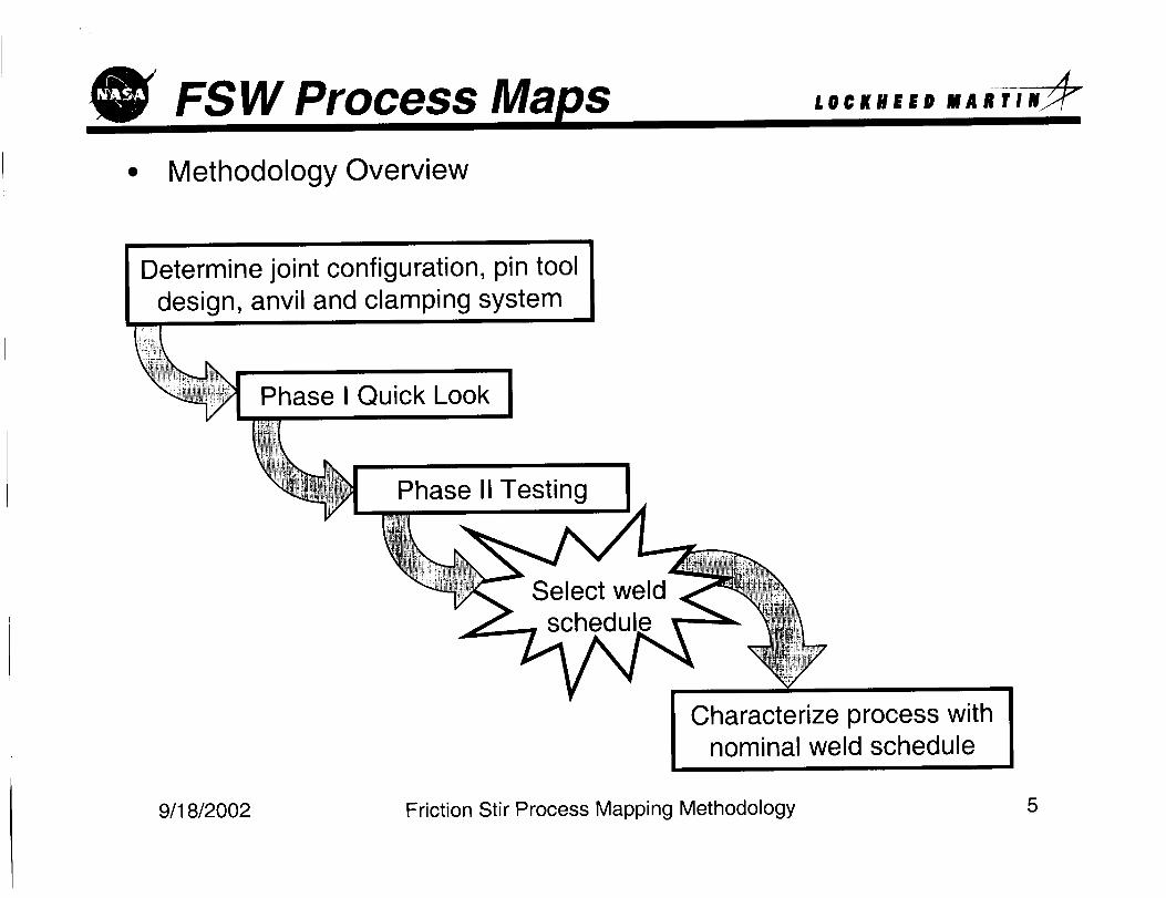
Methodology Overview
Determine joint configuration, pin tool
design, anvil and clamping system
Phase I Quick Look
Phase II Testing
Select weldschedu
Characterize process withnominal weld schedule
9/18/2002 Friction Stir Process Mapping Methodology 5
Phase I Quick Look L@¢KilEED MABTIN_
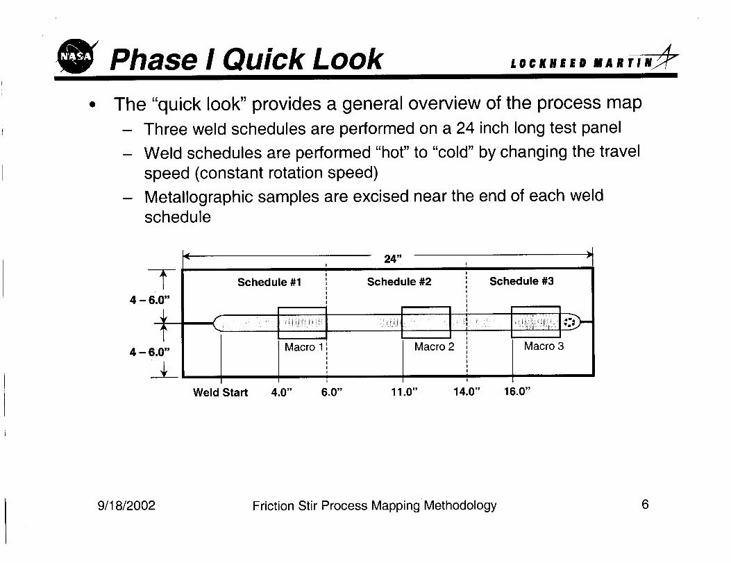
The "quick look" provides a general overview of the process map- Three weld schedules are performed on a 24 inch long test panel
- Weld schedules are performed "hot" to "cold" by changing the travel
speed (constant rotation speed)
- Metallographic samples are excised near the end of each weldschedule
I
-f- Sc.edu,e.1iI
4 - 6.0"i
4 - 6.0" Macro 1i,I
___ 'II
24"
Schedule #2
Macro 3
Weld Start 4.0"
I
: Schedule #3III
II
III
Macro 2 :IIIIIi
6.0" 11.0" 14.0" 16.0"
9/18/2002 Friction Stir Process Mapping Methodology 6
Z _00_/8 L/6/,6olopoq;alAl 6u!ddelhi $£eOOJd J!],cGuop,o!J-!
Bldl _dl
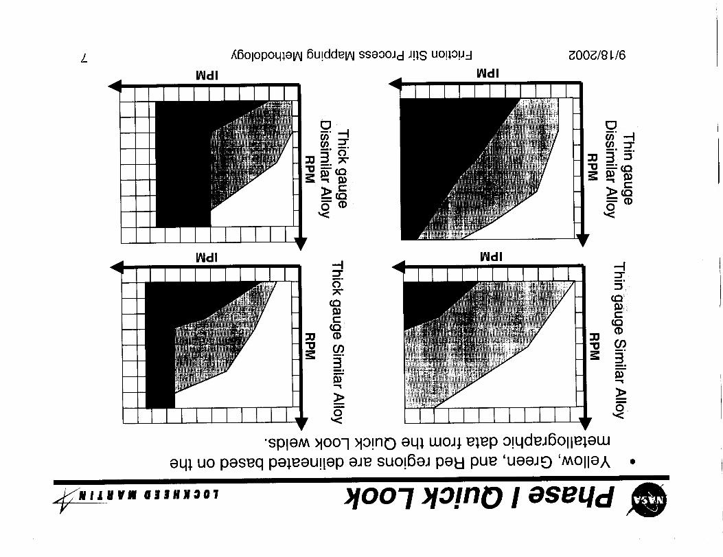
•spleM >lOOq_io!no eq_ woJ; e;ep o!qdeJ6olle;ew
eq_ uo peseq pe_eeu!lep aJe suo_6eJ peel pue 'ueeJE) 'MOlle,k
_R I I U V FI 8 | | ll J g O "I
Y )!oo'1 >io!no I eseLld __
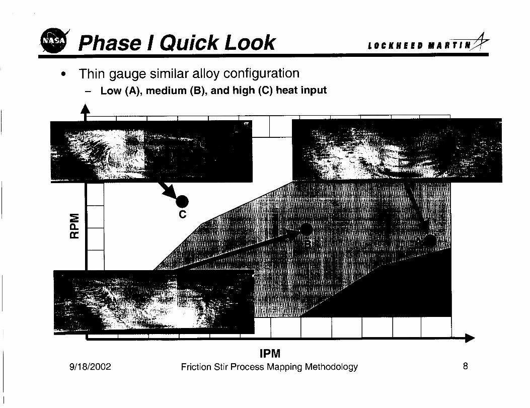
Phase I Quick Look LOCKllEED MARTIN_
Thin gauge similar alloy configuration- Low (A), medium (B), and high (C) heat input
C
IPM
Friction Stir Process Mapping Methodology9/18/2002 8
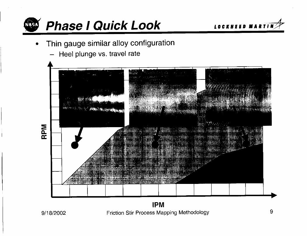
Phase I Quick Look
• Thin gauge similar alloy configuration
- Heel plunge vs. travel rate
/.@¢/(HEED
IPMFriction Stir Process Mapping Methodology9/18/2002 9
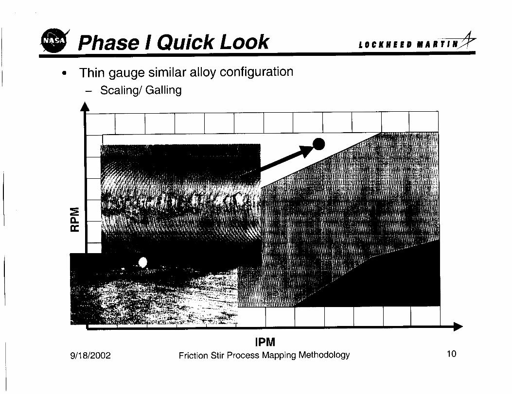
Phase I Quick Look L@¢KllEED MARTIN_
Thin gauge similar alloy configuration
- Scaling/Galling
IPMFriction Stir Process Mapping Methodology9/18/2002 10
LL _00_/8 L/6/,6olopoq;e_ 6u!ddelhl ssaooJd J!;S uo!lo!J-I
_dl
"U
_N I L I V iVY
Olt/IJO01
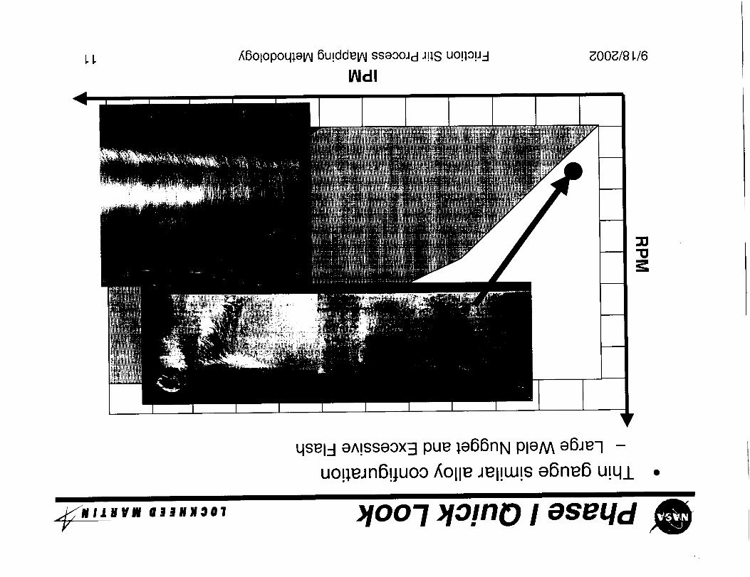
qsel-I e^!sseox3 pue ;e66nN pleM e6Jeq -
uo!_eJn6!juoo _Olle Jel!w!s e6ne6 u!qi
)!oo'7 >lo!no I aseqd
Phase I Quick Look ,,=,,,,° ,,,,,,_
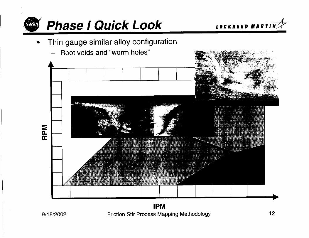
• Thin gauge similar alloy configuration- Root voids and "worm holes"
1'111
I:L
IPMFriction Stir Process Mapping Methodology9/18/2O02 12
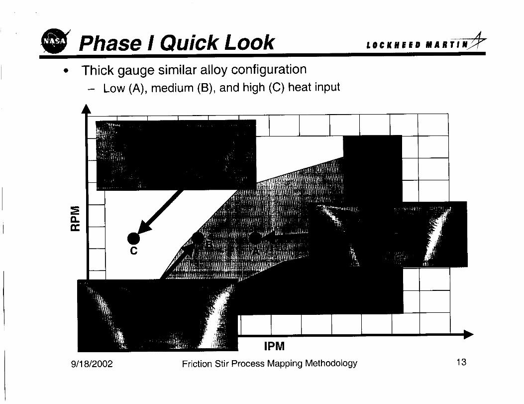
Phase I Quick Look• Thick gauge similar alloy configuration
- Low (A), medium (B), and high (C) heat input
LOCKHEED MABTIN_
C
IPM
Friction Stir Process Mapping Methodology9/18/2002 13
17L _00_/9 L/6_6olopoq;elhl 6u!ddelhl sseooJcl J!;S uo!;o!J-I
0
_NIIlVlJ 4II/IJOOTY
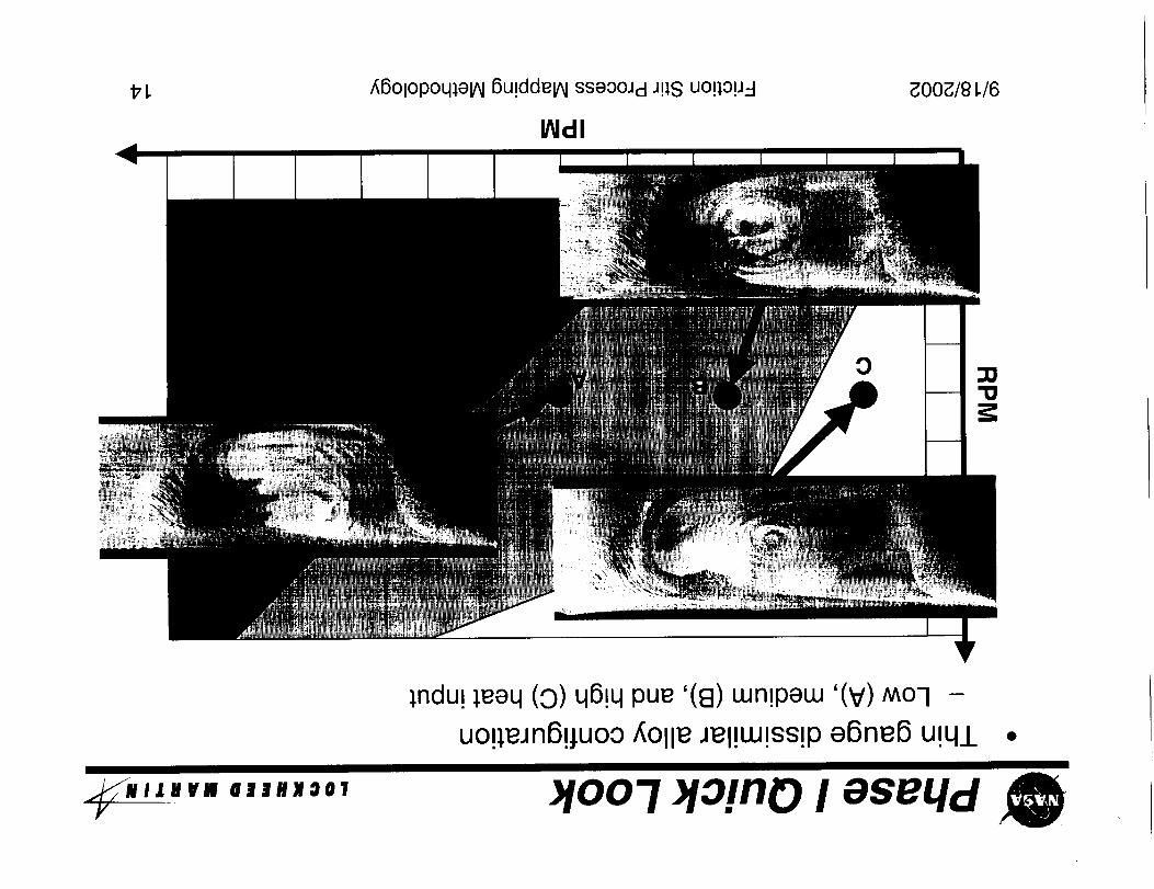
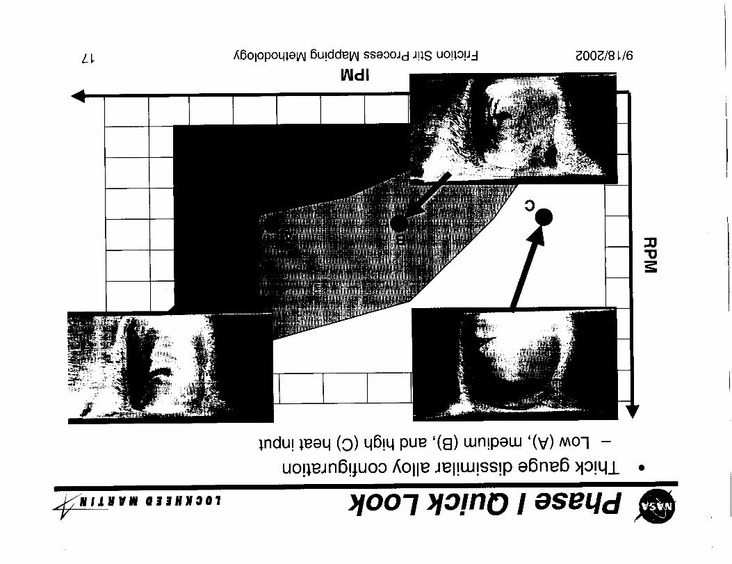
;ndu! ;eeq (0) q6!q pue '(8) wn!pew '(V) Mo-I -
uo!_eJn6!_uoo _Olle Jel!w!ss!p e6ne6 u!q_L
_!oo-I _lo!no I aseqd
£ I. _00_/81./6_6olopoqJ, e_ 6u!dde_ sseOOJd J!),S uop, ou_-I
_dl
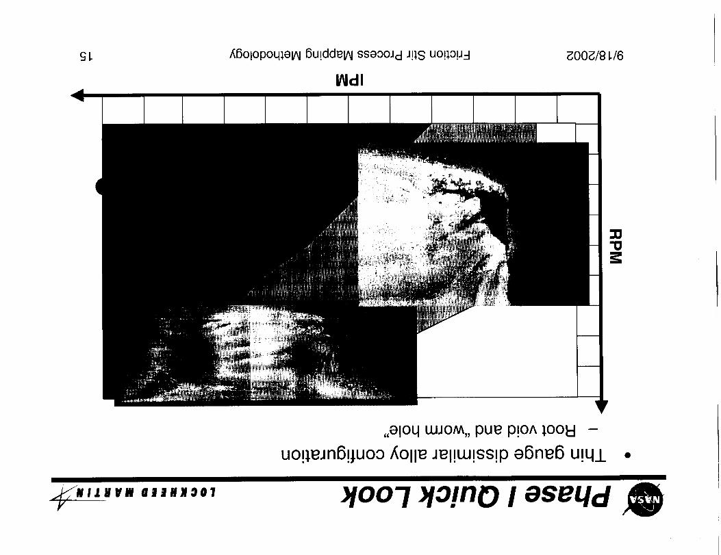
,,eloq LUJOM,,pue p!o^ _ool9 -
uo!;ejn6!juoo _Olle Jel!LU!ss!pe6ne6 u!q/
_" " ""v ""'°°' )!oo-I >io!no I eseLld
Phase I Quick Look L@¢KilEED MARTIN_
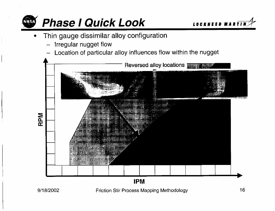
Thin gauge dissimilar alloy configurationIrregular nugget flow
Location of particular alloy influences flow within the nugget
Reversed alloy locations
IPM
Friction Stir Process Mapping Methodology9/18/2002 16
L L gOOg/8 L/6_6olopoqlelhl 6u!ddelhi sseooJd J!;S uo!lop=l
INdl
O
:12"12
;ndu! ;eeq (9) qB!q pue '(8) Lun!peLu'(V) Moq -
uo!;eJnB!juoo _Olle Jel!UJ!SS!pe6ne6 _lo!q/ °
_,,,,,, ,,,,,°" )!oo-I )lo!no I eseLld
8 L _00_/8 _/6/;6olopoq_elhl 6u!ddelhl ss8OOJd JP,S uo!:lO!J-I
_dl
"10
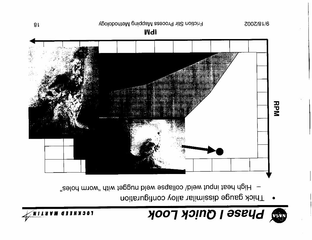
,,SalOq LUJOM,,ql!M le66nu PleM esdellOO/pleM lndu! ;eeq q6!H -
uo!;eJn6!_uoo f,Olle Jel!w!ss!pa6ne6 >io!q_L •
_,,,,,, ,,,,,°., _!oo-I _lo!no I eseqdy
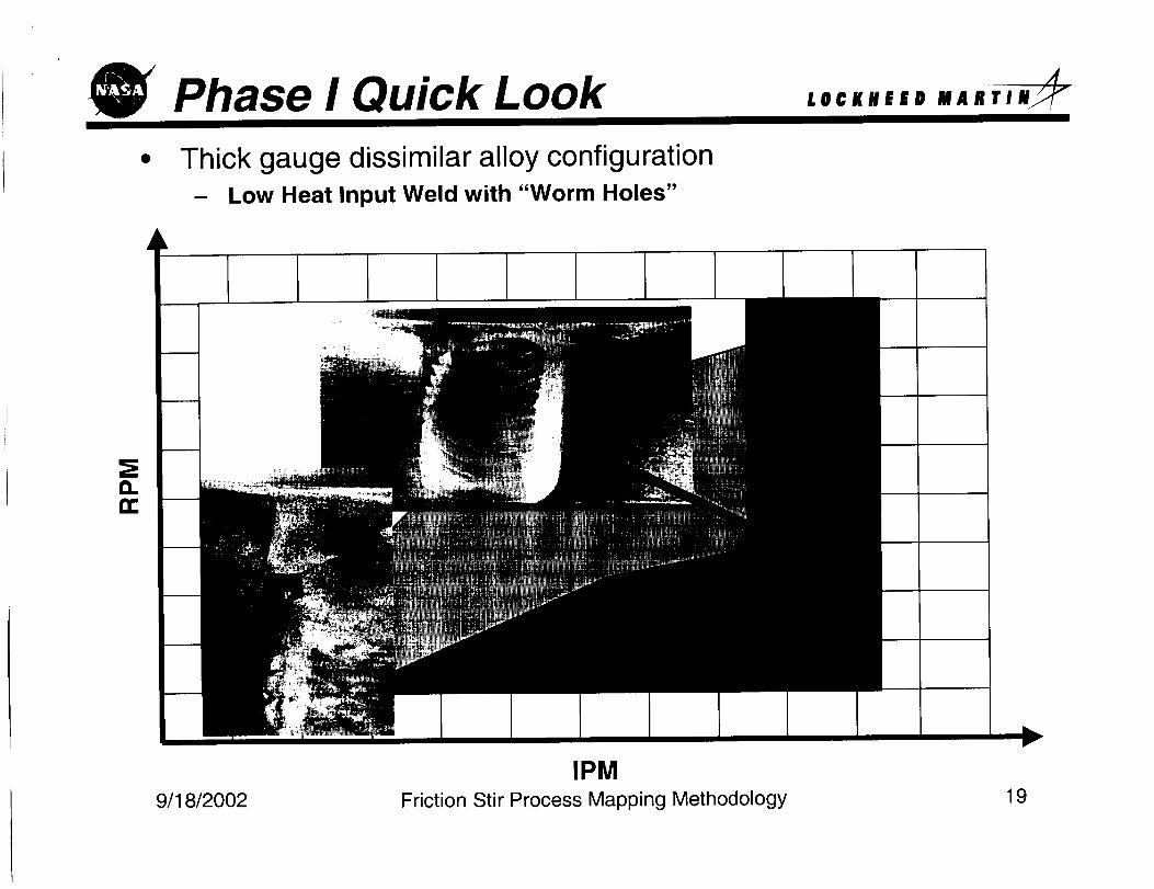
Phase I Quick Look
• Thick gauge dissimilar alloy configuration- Low Heat Input Weld with "Worm Holes"
LO©KHEED FI A R T I N_
G.
L
IPM
Friction Stir Process Mapping Methodology9/18/20O2 19
Phase II AL@©KllEED MARTIN_
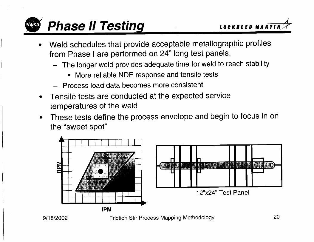
Weld schedules that provide acceptable metallographic profiles
from Phase I are performed on 24" long test panels.
- The longer weld provides adequate time for weld to reach stability
• More reliable NDE response and tensile tests
- Process load data becomes more consistent
Tensile tests are conducted at the expected service
temperatures of the weld
These tests define the process envelope and begin to focus in on
the "sweet spot"
W! | _IIMIWm | m t _J __J
12"x24" Test Panel
IPM
Friction Stir Process Mapping Methodology9/18/20O2 20
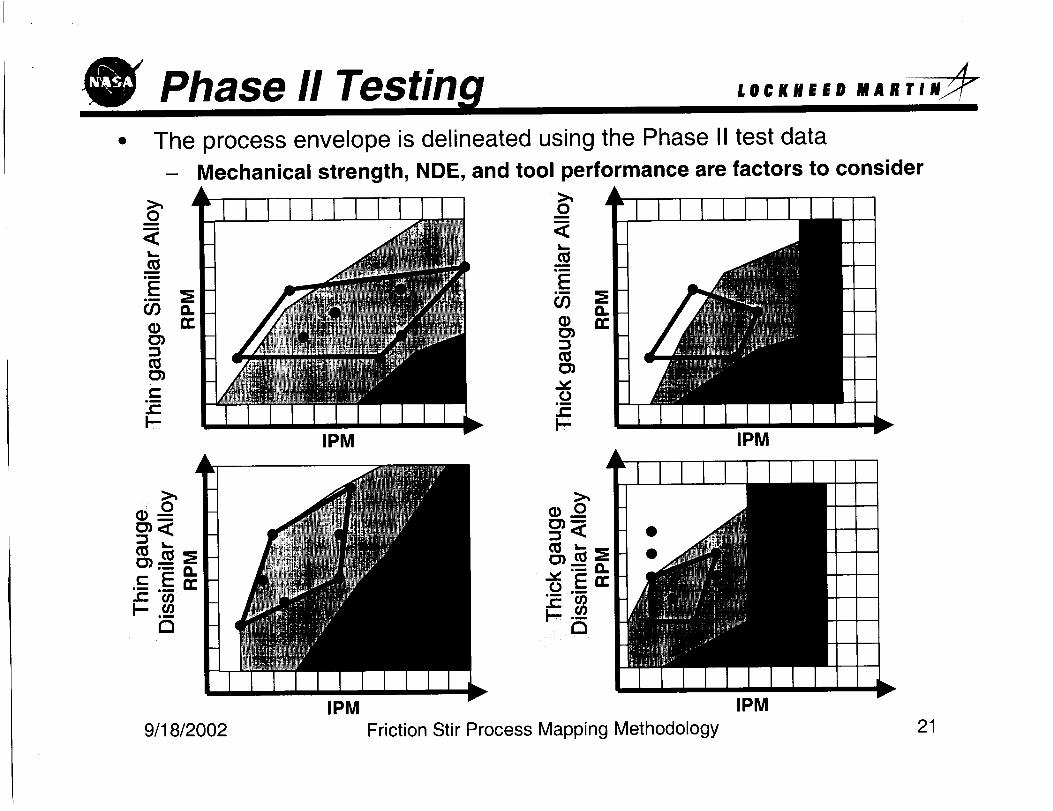
Phase II TestinThe process envelope is delineated using the Phase II test data
- Mechanical strength, NDE, and tool performance are factors to consider
IPM
0
0
IPM
9/18/2002 Friction Stir Process Mapping Methodology
IPM
IPM
21
Phase II Testin LO©KHEED
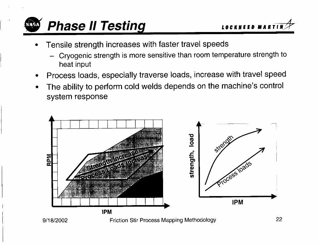
Tensile strength increases with faster travel speeds
- Cryogenic strength is more sensitive than room temperature strength to
heat input
Process loads, especially traverse loads, increase with travel speed
The ability to perform cold welds depends on the machine's control
system response
m
a. ==
IPM
IPM
Friction Stir Process Mapping Methodology
V
9/18/2002 22
Weld Schedule Selection LOCKHEED
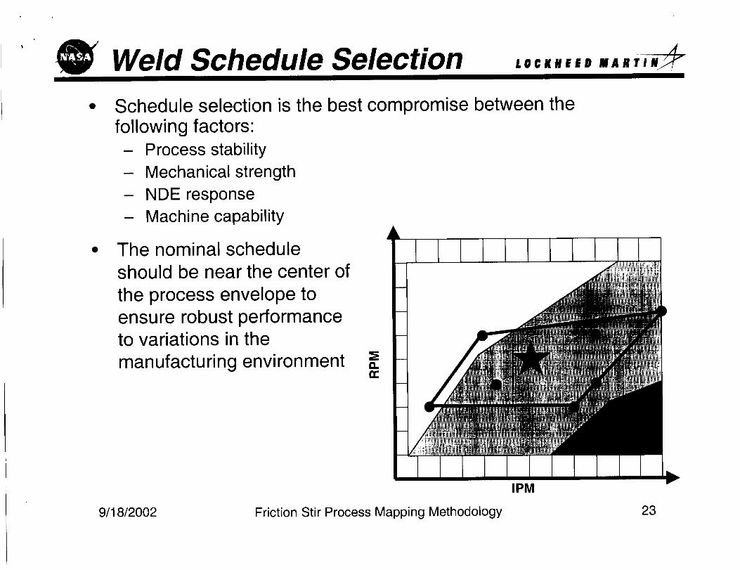
Schedule selection is the best compromise between thefollowing factors:
- Process stability
- Mechanical strength
- NDE response
- Machine capability
The nominal scheduleshould be near the center of
the process envelope toensure robust performanceto variations in the
manufacturing environment a.
MAHTIN_
IPM
9/18/2002 Friction Stir Process Mapping Methodology 23
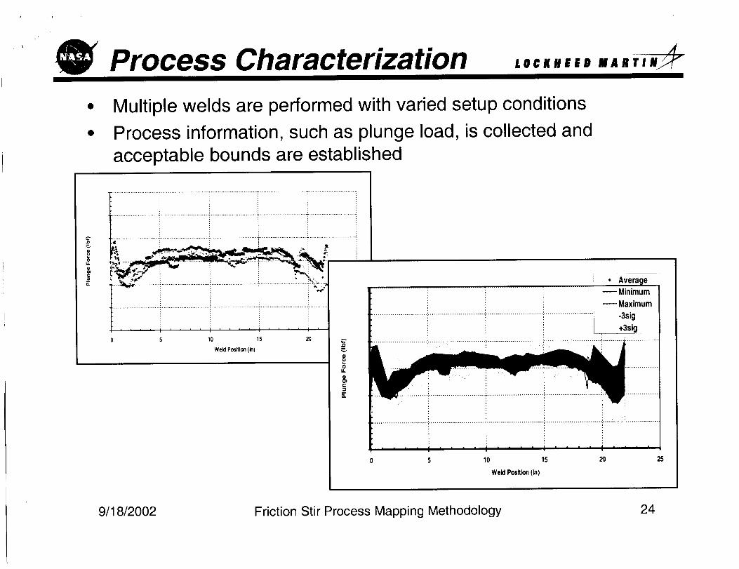
Process Characterization ,,,,.,,, ,,,,,.
Multiple welds are performed with varied setup conditions
Process information, such as plunge load, is collected and
acceptable bounds are established
I
.... I .... t i ' '10 15 20
Weld Position (in)
,,D
8
,qma.
• Average 1
Minimum
Maximum
-3sig
+3sig
i : i
5 10 15 20 25
We_Pos_n(_)
9/18/2002 Friction Stir Process Mapping Methodology 24
The weld process performance for a given weld jointconfiguration and tool setup is summarized on a 2-D plot ofRPM vs. IPM
A process envelope is drawn within the map to identify the
range of acceptable welds
The sweet spot is selected as the nominal weld schedule
The nominal weld schedule is characterized in the expected
manufacturing environment
The nominal weld schedule in conjunction with process control
ensures a consistent and predictable weld performance
9/18/2002 Friction Stir Process Mapping Methodology 25
Related Documents


![Solid State Friction Stir Welding (FSW) on Similar and ... · PDF fileGang and Feng [5] proposed simple ... Solid State Friction Stir Welding (FSW) on Similar and Dissimilar Metals](https://static.cupdf.com/doc/110x72/5aa3e49c7f8b9a07758ed7bd/solid-state-friction-stir-welding-fsw-on-similar-and-and-feng-5-proposed.jpg)