Integrated Command and Control System Frequentis ICCS 3020 System Description © FREQUENTIS 2006

Welcome message from author
This document is posted to help you gain knowledge. Please leave a comment to let me know what you think about it! Share it to your friends and learn new things together.
Transcript
Integrated Command and Control System
Frequentis ICCS 3020
System Description
© FREQUENTIS 2006

FREQUENTIS GmbH Spittelbreitengasse 34, A-1120 Vienna, DVR 0364797
SYSTEM DESCRIPTION FREQUENTIS ICCS 3020 Page: R-1 COPYRIGHT FREQUENTIS 2006 No.: 2706 Author: Frq
History Chart
Rev. Date Changed Page(s) Cause of Change Implemented
3.0 2006-03-20 All sections S. Ansari
3.1 2006-04-20 All sections T.Abfalter
No. Action Name Signature Date Department
1 Prepared T. Abfalter 2006-07-21 PS
2 Approved P. Pickem 2006-08-02 PS
3 Released C. Flachberger 2006-08-02 PS All rights reserved. No part of the document may be reproduced or transmitted in any form or by any means, electronic or mechanical, for any purpose, without the written permission of FREQUENTIS GmbH. Company or product names mentioned in this document may be trademarks or registered trademarks of their respective companies.
Introduction
SYSTEM DESCRIPTION FREQUENTIS ICCS 3020 Page: C-1 COPYRIGHT FREQUENTIS 2006 No.: 2706 Author: Frq
Contents
1. Introduction....................................... ...................................1-3
1.1. Purpose.............................................................................................................1-3
1.2. Target Group.....................................................................................................1-3
1.3. Usage ...............................................................................................................1-3 1.3.1. Structure of Document ......................................................................................1-3 1.3.2. Typographical Conventions...............................................................................1-3
2. FREQUENTIS ICCS 3020 .....................................................2-3
2.1. System Overview ..............................................................................................2-3
2.2. System Highlights .............................................................................................2-3
3. System Architecture................................ ............................3-3
3.1. Operator Working Position ................................................................................3-3
3.2. Switch ...............................................................................................................3-3
3.3. The Interface Part .............................................................................................3-3
3.4. Technical Monitoring and Control System .........................................................3-3
4. Graphical User Interface ........................... ..........................4-3
4.1. Status bar..........................................................................................................4-3
4.2. Resource area...................................................................................................4-3
4.3. Function key row...............................................................................................4-3
4.4. GUI Functions ...................................................................................................4-3
5. Operational Services ............................... ............................5-3
5.1. General Services...............................................................................................5-3 5.1.1. Settings.............................................................................................................5-3 5.1.2. Chime Mute.......................................................................................................5-3 5.1.3. Microphone Mute ..............................................................................................5-3 5.1.4. Instant Playback................................................................................................5-3 5.1.5. Help ..................................................................................................................5-3
5.2. Telephone Services ..........................................................................................5-3 5.2.1. Incoming Call ....................................................................................................5-3 5.2.2. Initiating Call .....................................................................................................5-3 5.2.3. Transfer.............................................................................................................5-3 5.2.4. Hold / Toggle.....................................................................................................5-3 5.2.5. Conference .......................................................................................................5-3 5.2.6. Automatic Call Distribution (Option)...................................................................5-3 5.2.7. Dial Pad ............................................................................................................5-3 5.2.8. Request Assistance ..........................................................................................5-3
Introduction
SYSTEM DESCRIPTION FREQUENTIS ICCS 3020 Page: C-2 COPYRIGHT FREQUENTIS 2006 No.: 2706 Author: Frq
5.2.9. Conference Parties ...........................................................................................5-3 5.2.10. Speed Dial ........................................................................................................5-3 5.2.11. Telephone History .............................................................................................5-3 5.2.12. Intercom............................................................................................................5-3 5.2.13. Waiting Calls .....................................................................................................5-3
5.3. Analogue Radio Services ..................................................................................5-3 5.3.1. De-Monitor ........................................................................................................5-3 5.3.2. De-Monitor All ...................................................................................................5-3 5.3.3. De-Select All .....................................................................................................5-3 5.3.4. De-Activate .......................................................................................................5-3 5.3.5. Mute Monitored .................................................................................................5-3 5.3.6. Un-Mute Monitored ...........................................................................................5-3 5.3.7. Focus on Talk-group .........................................................................................5-3 5.3.8. Patch.................................................................................................................5-3 5.3.9. Cross-connect ...................................................................................................5-3 5.3.10. Disable PTT on Patch .......................................................................................5-3
5.4. Digital Trunked Radio Services (Option)............................................................5-3 5.4.1. Radio Area ........................................................................................................5-3 5.4.1.1. Affiliation ...........................................................................................................5-3 5.4.1.2. Status................................................................................................................5-3 5.4.1.3. Text Messages..................................................................................................5-3 5.4.1.4. Event Monitoring ...............................................................................................5-3 5.4.2. Add Subscriber..................................................................................................5-3 5.4.3. Remove Subscriber...........................................................................................5-3 5.4.4. Stun Mobile .......................................................................................................5-3 5.4.5. Send Alert Tone ................................................................................................5-3 5.4.6. Short Data Services (SDS)................................................................................5-3 5.4.7. Private Call........................................................................................................5-3 5.4.8. Ambient Listening..............................................................................................5-3 5.4.9. Alert Tone selection ..........................................................................................5-3
5.5. Supervisory Services.........................................................................................5-3 5.5.1. Operational Alarms ...........................................................................................5-3 5.5.2. Suggest.............................................................................................................5-3 5.5.3. Intervene...........................................................................................................5-3 5.5.4. Grab Call...........................................................................................................5-3 5.5.5. Eavesdrop.........................................................................................................5-3 5.5.5.1. Covert Eavesdrop .............................................................................................5-3 5.5.5.2. End Eavesdrop..................................................................................................5-3
6. Networking and Remote Control ...................... ..................6-3
7. Role Management .................................... ............................7-3
7.1. Role Contents ...................................................................................................7-3
7.2. Role Selection...................................................................................................7-3
7.3. User Profiles .....................................................................................................7-3
7.4. Personal User Settings..........................................Error! Bookmark not defined.
Introduction
SYSTEM DESCRIPTION FREQUENTIS ICCS 3020 Page: C-3 COPYRIGHT FREQUENTIS 2006 No.: 2706 Author: Frq
8. Interfaces......................................... .....................................8-3
8.1. Analogue Radio.................................................................................................8-3
8.2. Analogue Telephone .........................................................................................8-3
8.3. Digital Trunked Radio........................................................................................8-3
8.4. Digital Telephone ..............................................................................................8-3
8.5. Digital I/O ..........................................................................................................8-3
8.6. Serial Data Interfaces........................................................................................8-3
8.7. Recording Interfaces .........................................................................................8-3
8.8. Network Interfaces ............................................................................................8-3
9. Technical Monitoring and Control System ............ ............9-3
9.1. Parameter Editor ...............................................................................................9-3
9.2. ELMAS..............................................................................................................9-3 9.2.1. Logging of ICCS 3020 Status and Error Events.................................................9-3 9.2.2. Interconnected ICCS 3020 Sites have Common State Reporting......................9-3 9.2.3. Interface to ELMAS Database ...........................................................................9-3 9.2.4. SNMP Interface.................................................................................................9-3
10. External Systems................................... ............................10-3
10.1. External Clock.................................................................................................10-3
10.2. Legal Voice Recording ....................................................................................10-3
10.3. CAD.NET ........................................................................................................10-3
11. Technical Specifications ........................... ........................11-3
11.1. System Performance.......................................................................................11-3
11.2. Interface Characteristics..................................................................................11-3 11.2.1. Telephone Interfaces.......................................................................................11-3 11.2.2. Radio Interfaces..............................................................................................11-3
11.3. Environment....................................................................................................11-3 11.3.1. Power Supply..................................................................................................11-3 11.3.2. Ambient Environment for Operation ................................................................11-3 11.3.3. Ambient Environment for Transport.................................................................11-3 11.3.4. Electromagnetic Compatibility .........................................................................11-3
12. Abbreviations and Acronyms ......................... ..................12-3
Illustrations
Fig. 2-1: Standardised User Interface for Every Communication Channel .......................2-3 Fig. 3-1: FREQUENTIS ICCS 3020 System Architecture ................................................3-3 Fig. 3-2: FREQUENTIS ICCS 3020 Operator Position ....................................................3-3
Introduction
SYSTEM DESCRIPTION FREQUENTIS ICCS 3020 Page: C-4 COPYRIGHT FREQUENTIS 2006 No.: 2706 Author: Frq
Fig. 4-1: GUI main page..................................................................................................4-3 Fig. 4-2: Status bar..........................................................................................................4-3 Fig. 4-3: Resource area...................................................................................................4-3 Fig. 4-4: Function key row...............................................................................................4-3 Fig. 5-1: Settings Window ...............................................................................................5-3 Fig. 5-2: Instant Playback................................................................................................5-3 Fig. 5-3: Help Screen ......................................................................................................5-3 Fig. 5-4: Dial Pad Window, Telephony Mode...................................................................5-3 Fig. 5-5: Speed Dial ........................................................................................................5-3 Fig. 5-6: Intercom............................................................................................................5-3 Fig. 5-7: Waiting Calls .....................................................................................................5-3 Fig. 5-8: Radio Area ........................................................................................................5-3 Fig. 5-9: Affiliation Tab folder, Focus on talk-group .........................................................5-3 Fig. 5-10: Radio Status Tab Folder ...................................................................................5-3 Fig. 5-11: Radio Text Messages Tab Folder......................................................................5-3 Fig. 5-12: Radio Event Monitoring Tab Folder ...................................................................5-3 Fig. 5-13: Send Text Message, enter via keyboard ...........................................................5-3 Fig. 5-14: Send Text Message, add from Template...........................................................5-3 Fig. 5-15: Alert Tone Selection in Setting Page Window ...................................................5-3 Fig. 5-16: Operational Alarms & and Port Usage Window .................................................5-3 Fig. 6-1: Networked ICCS 3020 Systems ........................................................................6-3 Fig. 9-1: Parameter Editor ...............................................................................................9-3 Fig. 10-1: Application Interface with CAD .NET ...............................................................10-3
Tables Tab. 4-1: Button appearances ..........................................................................................4-3 Tab. 4-2: Resource area description ................................................................................4-3 Tab. 4-3: Fixed buttons in function key row ......................................................................4-3
---------- END OF SECTION ----------
Introduction
SYSTEM DESCRIPTION FREQUENTIS ICCS 3020 Page: 1-1 COPYRIGHT FREQUENTIS 2006 No.: 2706 Author: Frq
1. Introduction
1.1. Purpose
The Product Description provides an overview of the Frequentis ICCS 3020 with a description of both, the architecture and specially the system features.
1.2. Target Group
The Product Description is intended for operators, engineers and project managers as well as persons who need detailed technical information about the Frequentis ICCS 3020.
1.3. Usage
1.3.1. Structure of Document
The Product Description describes the following topics:
System Benefits
System Architecture
Operator Working Position
Log on/off services
Operational services
Networking and Remote Control
Role Management
Interfaces
Technical Monitoring and Control System
External Systems
Technical Specifications
1.3.2. Typographical Conventions
The Product Description uses colour graphics to describe colour touch panel screens, and shows key texts in the functional descriptions. Colours and key texts shall be regarded as examples only.
Cross-references within the Product Description look like hyperlinks. If you work with a pdf-file of this Product Description, use the cross-references like hyperlinks.
---------- END OF SECTION ----------
FREQUENTIS ICCS 3020
SYSTEM DESCRIPTION FREQUENTIS ICCS 3020 Page: 2-1 COPYRIGHT FREQUENTIS 2006 No.: 2706 Author: Frq
2. FREQUENTIS ICCS 3020
Emergency services are working around the clock to help people. Command and control centres play a central role in their work. They serve as hubs and information centres where the missions are coordinated and directed. Voice and data communication is one of the key elements for handling emergency calls and managing incidents. Consequently, communication equipment is rated as mission critical and the Integrated Communication Control System (ICCS) can be seen as the heart of each centre.
2.1. System Overview
The FREQUENTIS ICCS 3020 is a high-end Integrated Communication Control System which is based on the proven and reliable 3020 series system family of FREQUENTIS Voice Communication Systems. It is specifically designed for command and control centres and addresses customers with very high requirements regarding reliability and functionality.
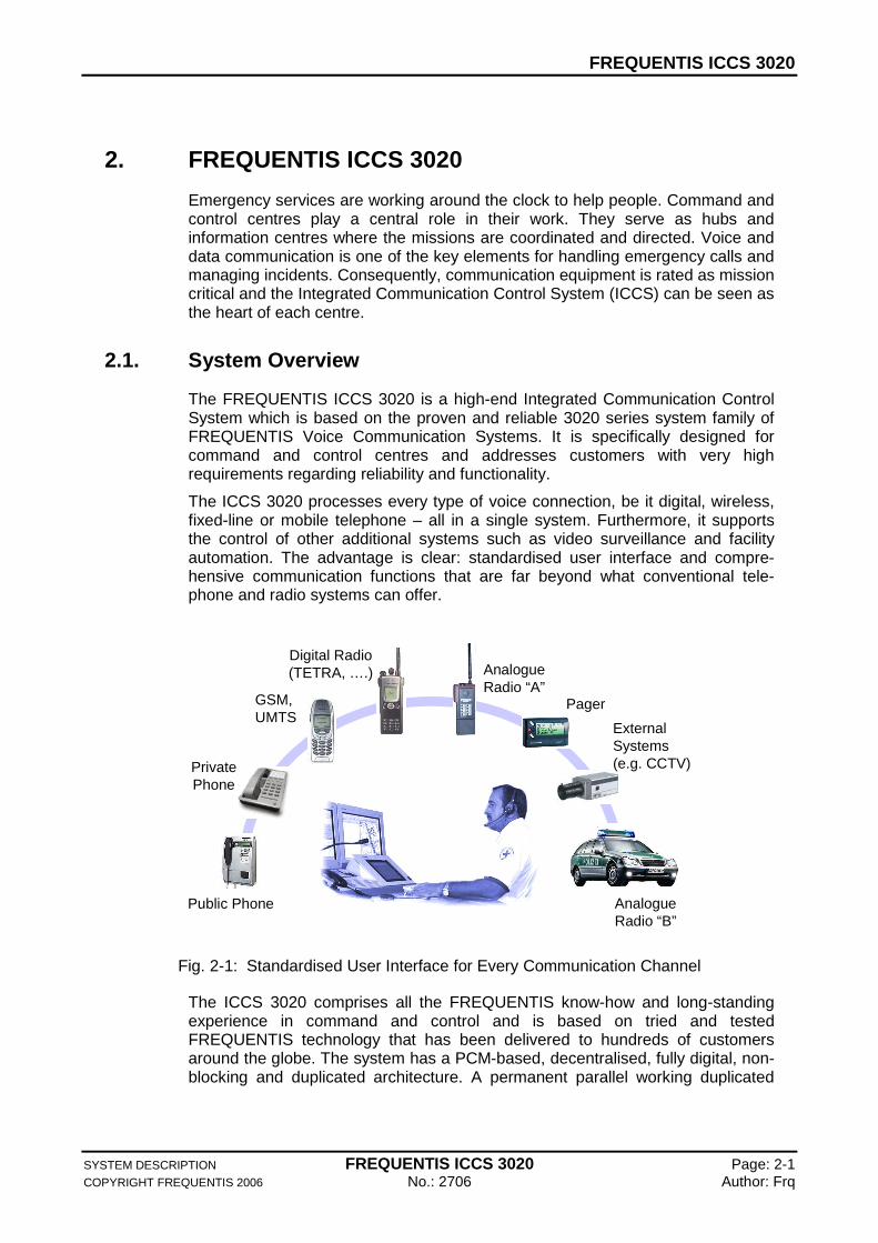
The ICCS 3020 processes every type of voice connection, be it digital, wireless, fixed-line or mobile telephone – all in a single system. Furthermore, it supports the control of other additional systems such as video surveillance and facility automation. The advantage is clear: standardised user interface and compre-hensive communication functions that are far beyond what conventional tele-phone and radio systems can offer.
Pager
Public Phone
GSM, UMTS
AnalogueRadio “A”
PrivatePhone
AnalogueRadio “B”
Digital Radio(TETRA, ….)
External Systems(e.g. CCTV)
Fig. 2-1: Standardised User Interface for Every Communication Channel
The ICCS 3020 comprises all the FREQUENTIS know-how and long-standing experience in command and control and is based on tried and tested FREQUENTIS technology that has been delivered to hundreds of customers around the globe. The system has a PCM-based, decentralised, fully digital, non-blocking and duplicated architecture. A permanent parallel working duplicated
FREQUENTIS ICCS 3020
SYSTEM DESCRIPTION FREQUENTIS ICCS 3020 Page: 2-2 COPYRIGHT FREQUENTIS 2006 No.: 2706 Author: Frq
core as well as telephone interfaces (and - optional - redundant radio interfaces) guarantee highest availability. The architecture provides enough system capacity to handle even the largest applications and guarantees a potential for cost-effective future system expansions.
PC-based workstations allow users to operate the ICCS 3020 in an easy manner. The users can control the entire system via a single ergonomic graphical user interface, which can be individually adapted to specific customer requirements. The system can be operated via touch screen, keyboard and mouse or – when integrated with other systems – via external applications.
Networking capabilities supporting meshed control rooms as well as add-on features such as facility management making the ICCS 3020 the optimal choice for command and control centres in public safety environments.
All in all, the ICCS 3020 provides all customers that demand the utmost in flexibility, functionality and fail safety.
2.2. System Highlights
The most important features and characteristics of the ICCS 3020 are:
Reliability and Fault Tolerance
Various customers have endorsed the unique parallel operating system architecture of the 3020 series of voice communication systems and its reliability. Continuous safety analysis procedures that adhere to international safety standards and an outstanding performance record document the unique safety characteristics of the ICCS 3020 architecture.
Decentralised, fully distributed system architecture
Unrivalled redundancy through operating core switches that work in parallel
Duplicated core switches can be separated for enhanced availability
Fully redundant resources for voice and data distribution
Very high System availability
Totally Non-Blocking System
The FREQUENTIS ICCS 3020 guarantees access to all communication channels by any operator at any time regardless of system load. It provides integrated voice communication for telephone and intercom (and optionally analogue and digital radio) in one single system.
Highest Voice Quality
FREQUENTIS ICCS 3020 guarantees highest voice quality based on fully digital voice processing from working position to interface.
FREQUENTIS ICCS 3020
SYSTEM DESCRIPTION FREQUENTIS ICCS 3020 Page: 2-3 COPYRIGHT FREQUENTIS 2006 No.: 2706 Author: Frq
Proven off the Shelf Hardware and Software
The application software as well as the core hardware of the ICCS 3020 are commercial off the shelf and have proven themselves in all of the FREQUENTIS installations throughout the world. Specific customer requirements have been continuously added to the application software within a regular release policy, a process that leads to continuous improvement of the system.
Modular System Architecture – Low Risk Customisatio n
A fully decentralised system architecture and modular system software give potential for quick and easy customisations. Due to the feature rich database of the COTS application gained from numerous customer programmes, adaptations can be kept at a minimum.
Low Life Cycle Cost
Universal hardware components reduce spare part stocks
Easy maintenance through true hot swap board replacement
Easy installation and adaptation through software configurable system parameters
No preventive maintenance required
Software controlled interface parameters – no manual adjustments of the interface hardware
High availability
Comprehensive Built In Test Equipment (BITE) and fault detection down to board level reduces maintenance time
Remote maintenance facility
10-year- lifetime support
Extensive Functionality and Flexibility
The FREQUENTIS ICCS 3020 provides a comprehensive range of functions for telephone and intercom (and optionally for analogue and digital radio, too). Features and operational functions can be enabled or disabled individually and be configured through software to allow easy adaptation to customer requirements.
FREQUENTIS ICCS 3020
SYSTEM DESCRIPTION FREQUENTIS ICCS 3020 Page: 2-4 COPYRIGHT FREQUENTIS 2006 No.: 2706 Author: Frq
Comprehensive Role- and User Management
The ICCS 3020 role management and user management has been designed to assign tasks and resources to working positions quickly and flexibly. User profiles provide secure access to systems facilities:
Role selection directly from working position
Network-wide role configuration and selection
Flexible assignment of resources and permissions
User log in with user name and password
Remote login / single sign-on from/with other systems
Wide Range of Digital and Analogue Interfaces
The interfaces used in the ICCS 3020 are proven in numerous system installations throughout the world. With only three different hardware types and a comprehensive set of software-configurable signalling almost any kind of analogue and digital line or radio Interface can be connected.
ICCS 3020 supports Euro-ISDN BRI and PRI and provides a comprehensive set of supplementary services.
Option: TETRA and Analogue Radio Features
The ICCS 3020 supports advanced features for public safety radio operation:
ICCS 3020 supports the major TETRA suppliers (e.g. Motorola, EADS/Nokia, Rohde & Schwarz) and, of course the FREQUENTIS eXtensible Trunked Radio System eXTRAS1.
ICCS 3020 supports a large range of analogue radio types.
Integrated Digital Networking Capabilities
Several ICCS 3020 systems can be integrated to form a large, distributed, virtual communication system:
Digital networking with 2 MBit/s E1 links
Distributed high availability of the total network supported by intelligent re-routing of radio and telephone traffic
Network-wide role management
Central or distributed network management
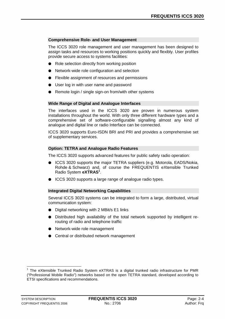
1 The eXtensible Trunked Radio System eXTRAS is a digital trunked radio infrastructure for PMR (“Professional Mobile Radio”) networks based on the open TETRA standard, developed according to ETSI specifications and recommendations.

FREQUENTIS ICCS 3020
SYSTEM DESCRIPTION FREQUENTIS ICCS 3020 Page: 2-5 COPYRIGHT FREQUENTIS 2006 No.: 2706 Author: Frq
Flexible and Graphical User Interface
The workstations of the FREQUENTIS ICCS 3020 are based on standard PCs which are equipped with high performance FREQUENTIS plug-in cards. Each workstation makes it possible to easily control every communication channel via a central user interface. The user interface can be individually adapted to specific customer requirements. It can be operated via touch screen, keyboard and mouse or – when integrated with other systems – via external applications.
State of the Art Management System
Highly modular and open systems architecture
Use of modern COTS software components
Easy integration of customer specific enhancements
Fully distributed systems and network management
Comprehensive database replication mechanisms (configuration, statistics)
Comprehensive system diagnosis and built in tests
Fully graphical and modular user interface design
Multiple workstations for maintenance and system supervision
Multiple user access levels and password restrictions
System event and traffic data collection
SNMP enabled
---------- END OF SECTION ----------
System Architecture
SYSTEM DESCRIPTION FREQUENTIS ICCS 3020 Page: 3-1 COPYRIGHT FREQUENTIS 2006 No.: 2706 Author: Frq
3. System Architecture
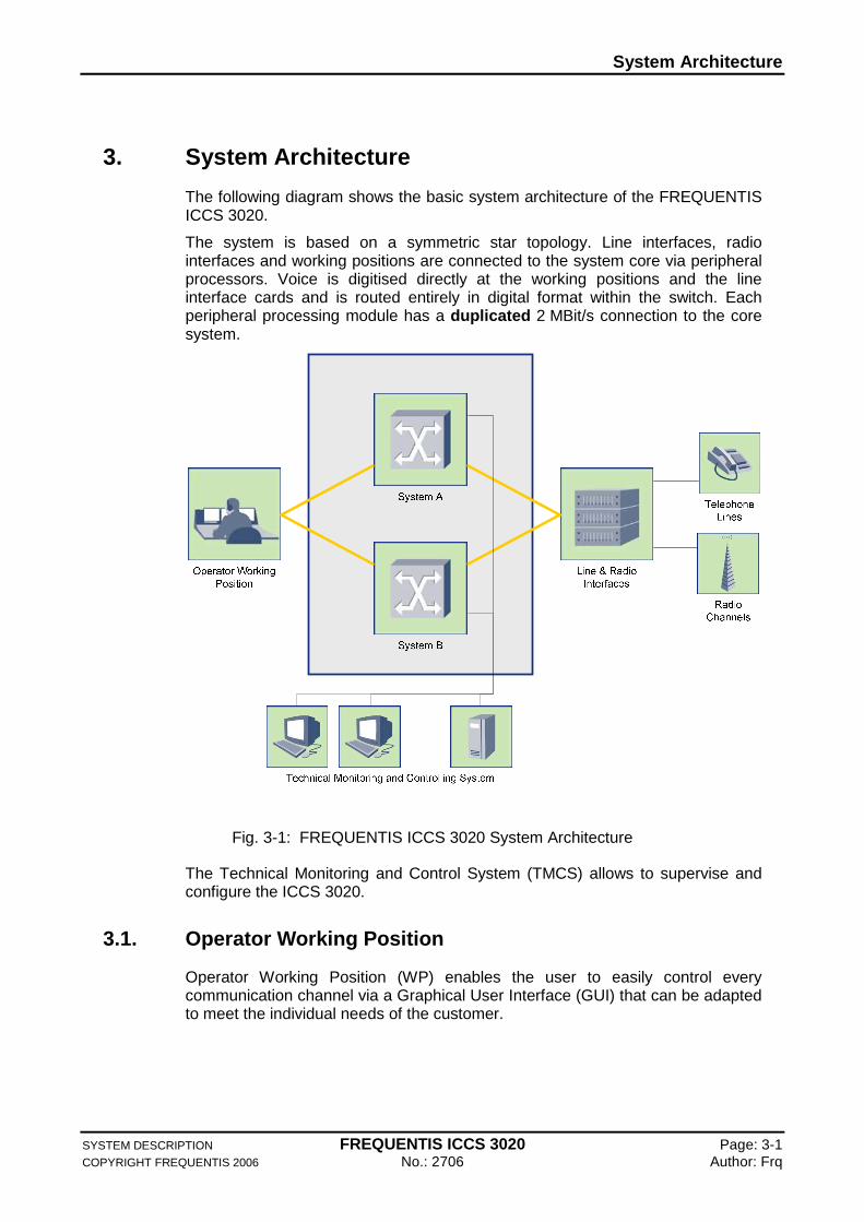
The following diagram shows the basic system architecture of the FREQUENTIS ICCS 3020.
The system is based on a symmetric star topology. Line interfaces, radio interfaces and working positions are connected to the system core via peripheral processors. Voice is digitised directly at the working positions and the line interface cards and is routed entirely in digital format within the switch. Each peripheral processing module has a duplicated 2 MBit/s connection to the core system.
Fig. 3-1: FREQUENTIS ICCS 3020 System Architecture
The Technical Monitoring and Control System (TMCS) allows to supervise and configure the ICCS 3020.
3.1. Operator Working Position
Operator Working Position (WP) enables the user to easily control every communication channel via a Graphical User Interface (GUI) that can be adapted to meet the individual needs of the customer.
System Architecture
SYSTEM DESCRIPTION FREQUENTIS ICCS 3020 Page: 3-2 COPYRIGHT FREQUENTIS 2006 No.: 2706 Author: Frq
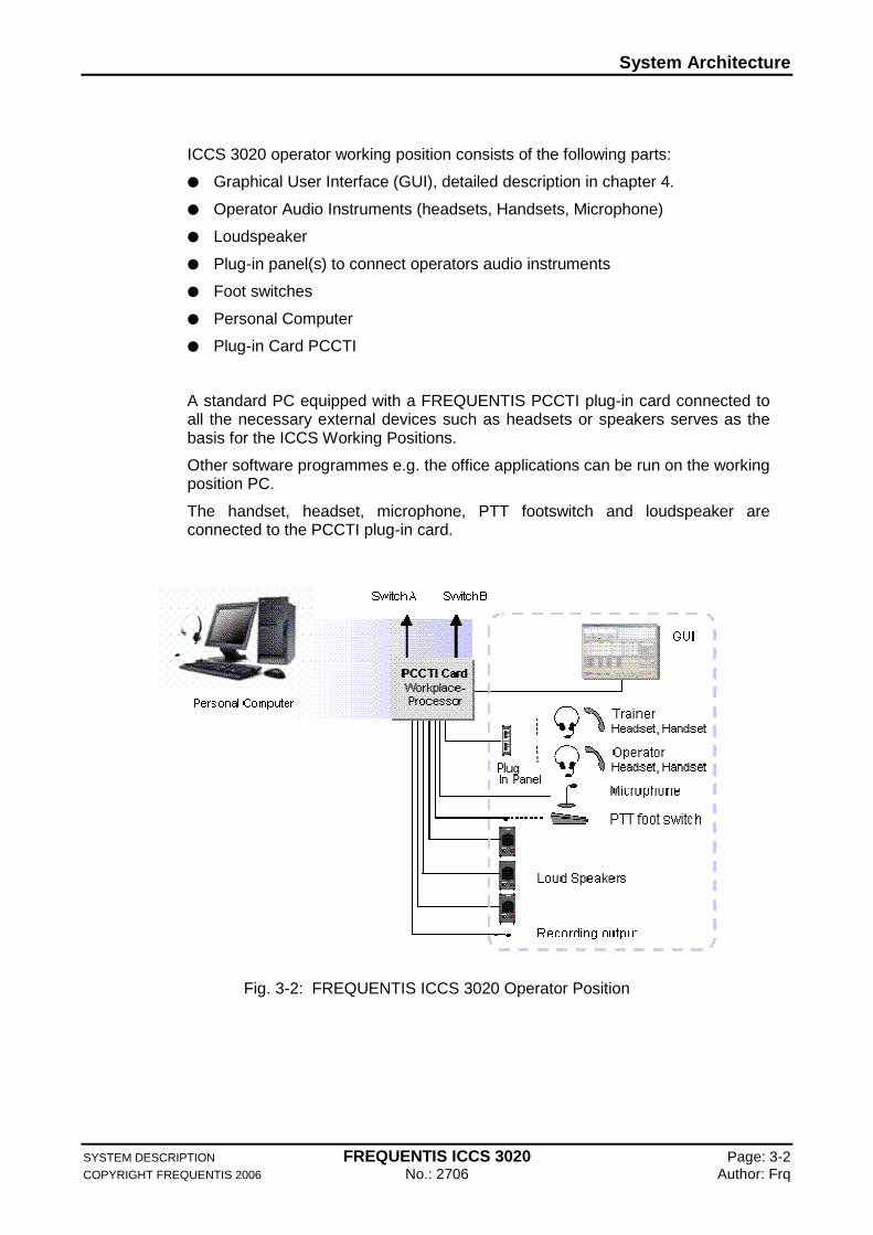
ICCS 3020 operator working position consists of the following parts:
Graphical User Interface (GUI), detailed description in chapter 4.
Operator Audio Instruments (headsets, Handsets, Microphone)
Loudspeaker
Plug-in panel(s) to connect operators audio instruments
Foot switches
Personal Computer
Plug-in Card PCCTI
A standard PC equipped with a FREQUENTIS PCCTI plug-in card connected to all the necessary external devices such as headsets or speakers serves as the basis for the ICCS Working Positions.
Other software programmes e.g. the office applications can be run on the working position PC.
The handset, headset, microphone, PTT footswitch and loudspeaker are connected to the PCCTI plug-in card.
Fig. 3-2: FREQUENTIS ICCS 3020 Operator Position
System Architecture
SYSTEM DESCRIPTION FREQUENTIS ICCS 3020 Page: 3-3 COPYRIGHT FREQUENTIS 2006 No.: 2706 Author: Frq
3.2. Switch
The two core switches systems A and B will operate continuously and at the same level of priority. The core system consists of the duplicated PCM switches, the duplicated data couplers and a duplicated clock system.
The core system is based on several modular digital switching and conferencing modules, which are all interconnected via system-wide PCM audio highways with Time Division Multiple Access (TDMA).
3.3. The Interface Part
The ICCS 3020 provides an extensive range of radio and telephone interfacing capability providing simple configuration for multiple, site specific interface types. The system can be directly connected to a wide range of communication equipment. Also special signalling protocols (e.g. for remote control) are available. The critical parameters of the interfaces are controlled by software.
Changes in the transmission levels or other similar interface characteristics can be performed quickly, without interruption of the switch operation.
No special test equipment is needed in case of Interface board exchanges. A common interfacing standard to the core switch enables the various telephone and radio interface cards to be arbitrarily organised within the shelf.
Interface board exchanges for maintenance purposes can be executed during normal operation. Exchanged line interfaces will be initialised automatically and do not have to be adjusted manually.
A comprehensive description of different interfaces can be found in chapter 8.
3.4. Technical Monitoring and Control System
Technical Monitoring and Control System (TMCS) fulfils the following tasks:
Management of Configuration Data
Software and Configuration Data Download
Collection and Display of System Fault Data
Collection of System Activity Statistical Data
Synchronisation to External Time Reference.
A comprehensive description of TMSC can be found in chapter 9.
---------- END OF SECTION ----------
Graphical User Interface
SYSTEM DESCRIPTION FREQUENTIS ICCS 3020 Page: 4-1 COPYRIGHT FREQUENTIS 2006 No.: 2706 Author: Frq
4. Graphical User Interface
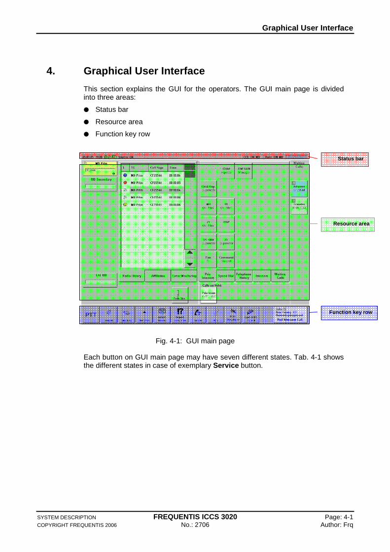
This section explains the GUI for the operators. The GUI main page is divided into three areas:
Status bar
Resource area
Function key row
Fig. 4-1: GUI main page
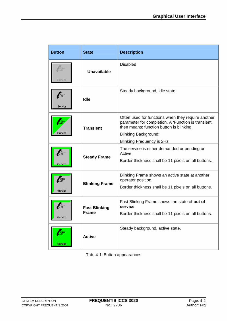
Each button on GUI main page may have seven different states. Tab. 4-1 shows the different states in case of exemplary Service button.
Status bar
Resource area
Function key row
Graphical User Interface
SYSTEM DESCRIPTION FREQUENTIS ICCS 3020 Page: 4-2 COPYRIGHT FREQUENTIS 2006 No.: 2706 Author: Frq
Button
State
Description
Unavailable
Disabled
Idle
Steady background, idle state
Transient
Often used for functions when they require another parameter for completion. A ‘Function is transient’ then means: function button is blinking.
Blinking Background;
Blinking Frequency is 2Hz
Steady Frame
The service is either demanded or pending or Active.
Border thickness shall be 11 pixels on all buttons.
Blinking Frame
Blinking Frame shows an active state at another operator position.
Border thickness shall be 11 pixels on all buttons.
Fast Blinking Frame
Fast Blinking Frame shows the state of out of service
Border thickness shall be 11 pixels on all buttons.
Active
Steady background, active state.
Tab. 4-1: Button appearances

Graphical User Interface
SYSTEM DESCRIPTION FREQUENTIS ICCS 3020 Page: 4-3 COPYRIGHT FREQUENTIS 2006 No.: 2706 Author: Frq
4.1. Status bar
Fig. 4-2: Status bar
The status bar provides the operators with special information about time, date, operator position status, and role name.
4.2. Resource area
The resource area provides the operators with special functions for telephone (and optional radio) and is subdivided into four areas explained in the Tab. 4-2 below :
Fig. 4-3: Resource area
1 Radio area. Displayed are up to 9 buttons representing pre-selected talk-groups (Airwave, Legacy and Conventional). The tab folders give access to further current information received.
2 Telephony and special functions area. Priority intercom calls can be initiated from here; speed-dial targets can be selected; the telephony call history can be inspected and used to re-call parties; a list of currently logged on users can be accessed to initiate intercom calls; and a list with all the calls waiting at this working position is available.
Resource Area
1
4
2
3
Graphical User Interface
SYSTEM DESCRIPTION FREQUENTIS ICCS 3020 Page: 4-4 COPYRIGHT FREQUENTIS 2006 No.: 2706 Author: Frq
3 Telephony Call Queue area. Here the call queues the user is assigned to are displayed.
4 Calls on hold area. Up to 4 calls can be put on hold.
Tab. 4-2: Resource area description
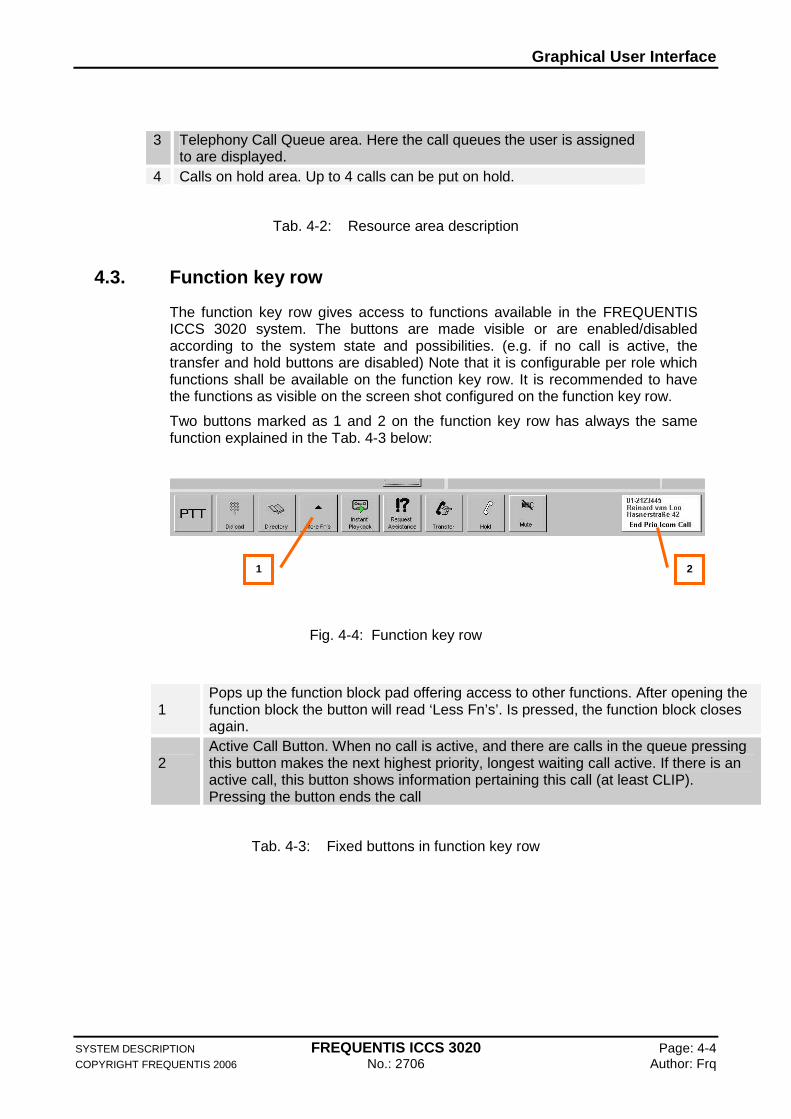
4.3. Function key row
The function key row gives access to functions available in the FREQUENTIS ICCS 3020 system. The buttons are made visible or are enabled/disabled according to the system state and possibilities. (e.g. if no call is active, the transfer and hold buttons are disabled) Note that it is configurable per role which functions shall be available on the function key row. It is recommended to have the functions as visible on the screen shot configured on the function key row.
Two buttons marked as 1 and 2 on the function key row has always the same function explained in the Tab. 4-3 below:
Fig. 4-4: Function key row
1
Pops up the function block pad offering access to other functions. After opening the function block the button will read ‘Less Fn’s’. Is pressed, the function block closes again.
2
Active Call Button. When no call is active, and there are calls in the queue pressing this button makes the next highest priority, longest waiting call active. If there is an active call, this button shows information pertaining this call (at least CLIP). Pressing the button ends the call
Tab. 4-3: Fixed buttons in function key row
1 2
Graphical User Interface
SYSTEM DESCRIPTION FREQUENTIS ICCS 3020 Page: 4-5 COPYRIGHT FREQUENTIS 2006 No.: 2706 Author: Frq
4.4. GUI Functions
All operator positions can be used interchangeably.
Permanent supervision of position electronic and information about the state of other positions.
Indication of any system component failure.
Individual configuration via TMCS.
Telephone calls can be operated with or without PTT.
Use of goose neck microphone and loudspeaker instead of handset/headset is possible.
All buttons are configurable via TMCS.
Level adjustment at the operator position.
---------- END OF SECTION ----------
Operational Services
SYSTEM DESCRIPTION FREQUENTIS ICCS 3020 Page: 5-1 COPYRIGHT FREQUENTIS 2006 No.: 2706 Author: Frq
5. Operational Services
This section explains the operational services of the FREQUENTIS ICCS 3020 for the user divided into following categories:
General Service
Telephone Services
Analogue Radio Services (Option)
Digital Radio Services (Option)
Supervisory Services
Statistics
5.1. General Services
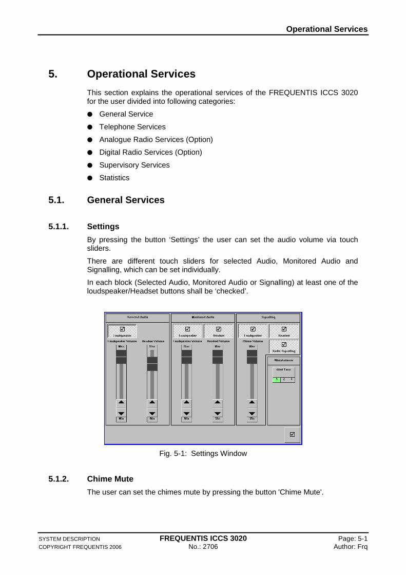
5.1.1. Settings
By pressing the button ‘Settings’ the user can set the audio volume via touch sliders.
There are different touch sliders for selected Audio, Monitored Audio and Signalling, which can be set individually.
In each block (Selected Audio, Monitored Audio or Signalling) at least one of the loudspeaker/Headset buttons shall be ‘checked’.
Fig. 5-1: Settings Window
5.1.2. Chime Mute
The user can set the chimes mute by pressing the button 'Chime Mute'.
Operational Services
SYSTEM DESCRIPTION FREQUENTIS ICCS 3020 Page: 5-2 COPYRIGHT FREQUENTIS 2006 No.: 2706 Author: Frq
All chimes of incoming calls are muted with the exception of:
Incoming calls from sources (lines/Queues), which are defined as sources for 'Emergency'-calls
Incoming emergency calls from radio systems
5.1.3. Microphone Mute
The user can set the microphone mute by pressing the function button ‘Mute Microphone’ from function key row.
The user can undo the action by pressing the button again.
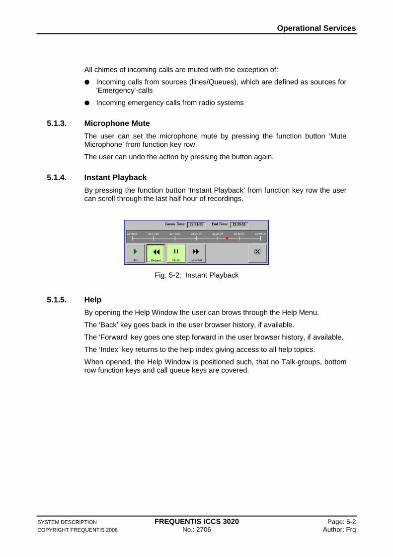
5.1.4. Instant Playback
By pressing the function button ‘Instant Playback’ from function key row the user can scroll through the last half hour of recordings.
Fig. 5-2: Instant Playback
5.1.5. Help
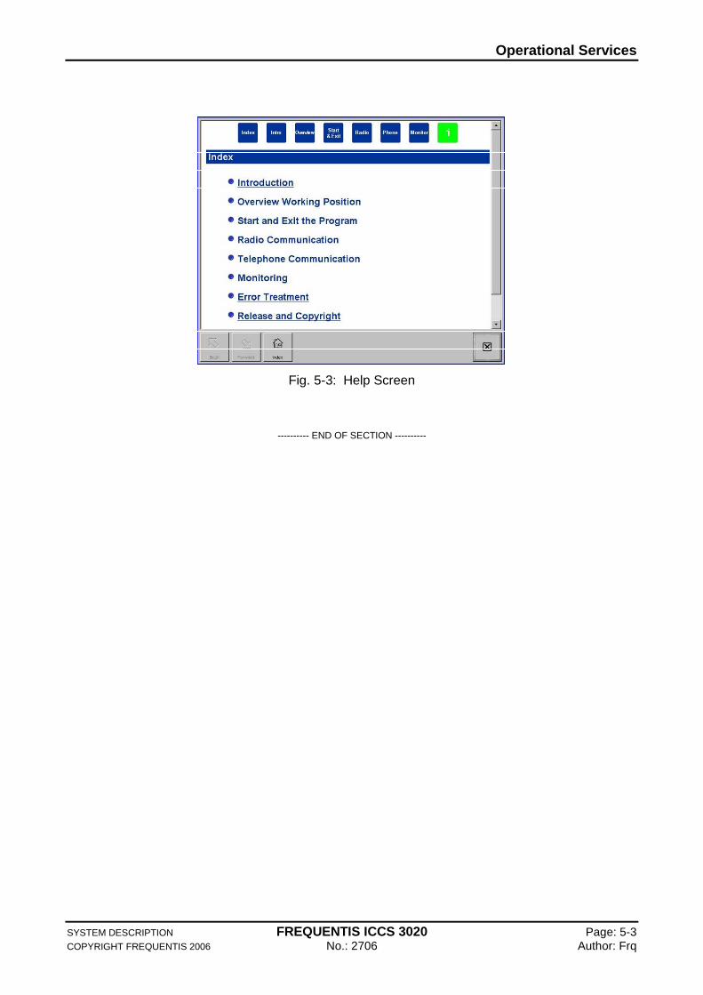
By opening the Help Window the user can brows through the Help Menu.
The ‘Back’ key goes back in the user browser history, if available.
The ‘Forward’ key goes one step forward in the user browser history, if available.
The ‘Index’ key returns to the help index giving access to all help topics.
When opened, the Help Window is positioned such, that no Talk-groups, bottom row function keys and call queue keys are covered.
Operational Services
SYSTEM DESCRIPTION FREQUENTIS ICCS 3020 Page: 5-3 COPYRIGHT FREQUENTIS 2006 No.: 2706 Author: Frq
Fig. 5-3: Help Screen
---------- END OF SECTION ----------
Operational Services
SYSTEM DESCRIPTION FREQUENTIS ICCS 3020 Page: 5-1 COPYRIGHT FREQUENTIS 2006 No.: 2706 Author: Frq
5.2. Telephone Services
This section explains the telephone services for the users.
5.2.1. Incoming Call
The incoming calls are displayed on the ‘Take Next Call’ button. Incoming calls are queued in a fist in first out (FIFO) order. The call with the highest priority and the longest waiting time is presented on the ‘Take next button’.
5.2.2. Initiating Call
The user can initiate a call in different ways:
By dialling the call target directly on ‘Dial Pad’ window, refer to 5.2.7 below
By pressing the ‘Direct Access’ keys
By selecting an entry from a list which contains the call target and then pressing the ‘Dial’ button
5.2.3. Transfer
After pressing the ‘Transfer’ button the user can select the transfer call target. By pressing the ‘Transfer’ button again the call is transferred to active call party.
5.2.4. Hold / Toggle
By pressing the ‘Hold’ button the user can interrupt the existing call and put it on hold. The user can re-establish the same call by pressing the ‘Hold’ button.
By pressing the ‘Toggle’ button the user can switch between the active call and the call on hold.
5.2.5. Conference
An active call can be set up to a conference with other parties. By pressing the ‘Conference’ button the user can select the conference target. By pressing the ‘Conference’ button again the conference is active.
To add further parties to the active conference the user should press the ‘Conference’ button again and select a new conference target.
A conference itself is represented as a call which can be active or on hold.
5.2.6. Automatic Call Distribution (Option)
Goal of the Automatic Call Distribution (ACD) functionality is to distribute received incoming calls among members of Call Targets which may be a working position, a group of working positions, a Role, a group of Roles or a user. The ACD mechanism is based on an idea of routing of the next received incoming call to the longest waiting member of Call Target.
Operational Services
SYSTEM DESCRIPTION FREQUENTIS ICCS 3020 Page: 5-2 COPYRIGHT FREQUENTIS 2006 No.: 2706 Author: Frq
Operators have the possibility to activate or de-activate ACD Ready mode at their working positions.
The ICCS 3020 System provides Automatic Call Distribution (ACD) functionality of the following characteristic:
An incoming call will be routed to the WP
The operator will be informed about the incoming ACD call by warning tone
ACD call received will be automatically answered by the position without an operator’s intervention – forced call talking
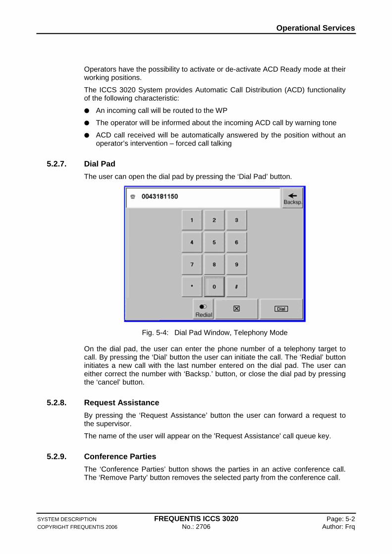
5.2.7. Dial Pad
The user can open the dial pad by pressing the ‘Dial Pad’ button.
Fig. 5-4: Dial Pad Window, Telephony Mode
On the dial pad, the user can enter the phone number of a telephony target to call. By pressing the ‘Dial’ button the user can initiate the call. The ‘Redial’ button initiates a new call with the last number entered on the dial pad. The user can either correct the number with ‘Backsp.’ button, or close the dial pad by pressing the ‘cancel’ button.
5.2.8. Request Assistance
By pressing the ‘Request Assistance’ button the user can forward a request to the supervisor.
The name of the user will appear on the 'Request Assistance' call queue key.
5.2.9. Conference Parties
The ‘Conference Parties’ button shows the parties in an active conference call. The ‘Remove Party’ button removes the selected party from the conference call.
Operational Services
SYSTEM DESCRIPTION FREQUENTIS ICCS 3020 Page: 5-3 COPYRIGHT FREQUENTIS 2006 No.: 2706 Author: Frq
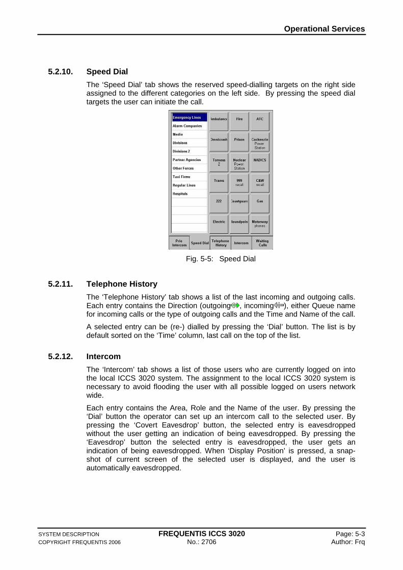
5.2.10. Speed Dial
The ‘Speed Dial’ tab shows the reserved speed-dialling targets on the right side assigned to the different categories on the left side. By pressing the speed dial targets the user can initiate the call.
Fig. 5-5: Speed Dial
5.2.11. Telephone History
The ‘Telephone History’ tab shows a list of the last incoming and outgoing calls. Each entry contains the Direction (outgoing , incoming ), either Queue name for incoming calls or the type of outgoing calls and the Time and Name of the call.
A selected entry can be (re-) dialled by pressing the ‘Dial’ button. The list is by default sorted on the ‘Time’ column, last call on the top of the list.
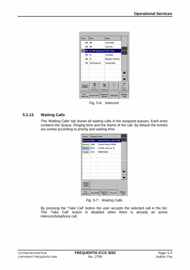
5.2.12. Intercom
The ‘Intercom’ tab shows a list of those users who are currently logged on into the local ICCS 3020 system. The assignment to the local ICCS 3020 system is necessary to avoid flooding the user with all possible logged on users network wide.
Each entry contains the Area, Role and the Name of the user. By pressing the ‘Dial’ button the operator can set up an intercom call to the selected user. By pressing the ‘Covert Eavesdrop’ button, the selected entry is eavesdropped without the user getting an indication of being eavesdropped. By pressing the ‘Eavesdrop’ button the selected entry is eavesdropped, the user gets an indication of being eavesdropped. When ‘Display Position’ is pressed, a snap-shot of current screen of the selected user is displayed, and the user is automatically eavesdropped.
Operational Services
SYSTEM DESCRIPTION FREQUENTIS ICCS 3020 Page: 5-4 COPYRIGHT FREQUENTIS 2006 No.: 2706 Author: Frq
Fig. 5-6: Intercom
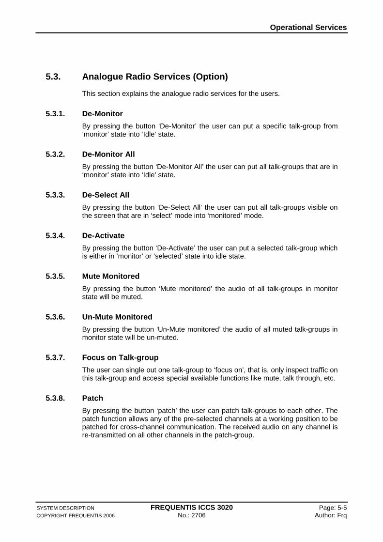
5.2.13. Waiting Calls
The ‘Waiting Calls’ tab shows all waiting calls in the assigned queues. Each entry contains the Queue, Ringing time and the Name of the call. By default the entries are sorted according to priority and waiting time.
Fig. 5-7: Waiting Calls
By pressing the ‘Take Call’ button the user accepts the selected call in the list. The ‘Take Call’ button is disabled when there is already an active intercom/telephony call.
Operational Services
SYSTEM DESCRIPTION FREQUENTIS ICCS 3020 Page: 5-5 COPYRIGHT FREQUENTIS 2006 No.: 2706 Author: Frq
5.3. Analogue Radio Services (Option)
This section explains the analogue radio services for the users.
5.3.1. De-Monitor
By pressing the button ‘De-Monitor’ the user can put a specific talk-group from ‘monitor’ state into ‘Idle’ state.
5.3.2. De-Monitor All
By pressing the button ‘De-Monitor All’ the user can put all talk-groups that are in ‘monitor’ state into ‘Idle’ state.
5.3.3. De-Select All
By pressing the button ‘De-Select All’ the user can put all talk-groups visible on the screen that are in ‘select’ mode into ‘monitored’ mode.
5.3.4. De-Activate
By pressing the button ‘De-Activate’ the user can put a selected talk-group which is either in ‘monitor’ or ‘selected’ state into idle state.
5.3.5. Mute Monitored
By pressing the button ‘Mute monitored’ the audio of all talk-groups in monitor state will be muted.
5.3.6. Un-Mute Monitored
By pressing the button ‘Un-Mute monitored’ the audio of all muted talk-groups in monitor state will be un-muted.
5.3.7. Focus on Talk-group
The user can single out one talk-group to ‘focus on’, that is, only inspect traffic on this talk-group and access special available functions like mute, talk through, etc.
5.3.8. Patch
By pressing the button ‘patch’ the user can patch talk-groups to each other. The patch function allows any of the pre-selected channels at a working position to be patched for cross-channel communication. The received audio on any channel is re-transmitted on all other channels in the patch-group.

Operational Services
SYSTEM DESCRIPTION FREQUENTIS ICCS 3020 Page: 5-6 COPYRIGHT FREQUENTIS 2006 No.: 2706 Author: Frq
5.3.9. Cross-connect
By pressing the button ‘Cross-Connect’ the user can cross-connect a telephone call with a radio channel. The button is enabled while the telephone call is active.
It is possible to cross-connect one active telephone call or a conference with a talk-group.
5.3.10. Disable PTT on Patch
This function is used to put a patch into ‘the background’. When pressing PTT the user is not transmitting on this patch. PTT on a Patch can be enabled again by pressing one of the talk-groups involved.
5.4. Digital Trunked Radio Services (Option)
This section explains the digital trunked radio services for the users.
5.4.1. Radio Area
Radio area is a sub area of GUI main page ‘Resource area’ which is subdivided in two parts:
Fig. 5-8: Radio Area
1 Visible Talk-Groups. The talk-groups visible here can be: Pre-configured to appear after role selection, and Added/removed by the user manually.
1 2
Operational Services
SYSTEM DESCRIPTION FREQUENTIS ICCS 3020 Page: 5-7 COPYRIGHT FREQUENTIS 2006 No.: 2706 Author: Frq
2 Radio tab-folder ‘Radio History’, ‘Affiliation’ and ‘Event Monitoring’. Here displayed with ‘Status’ and ‘Text Messages’ tab-folders not visible.
The radio tab-folder area contains ‘Status’, ‘Affiliation, ‘Radio History’ and ‘Event Monitoring’ pertaining mostly to talk-groups. Also, when focussing on a talk-group radio area offers access to some talk-group control functions.
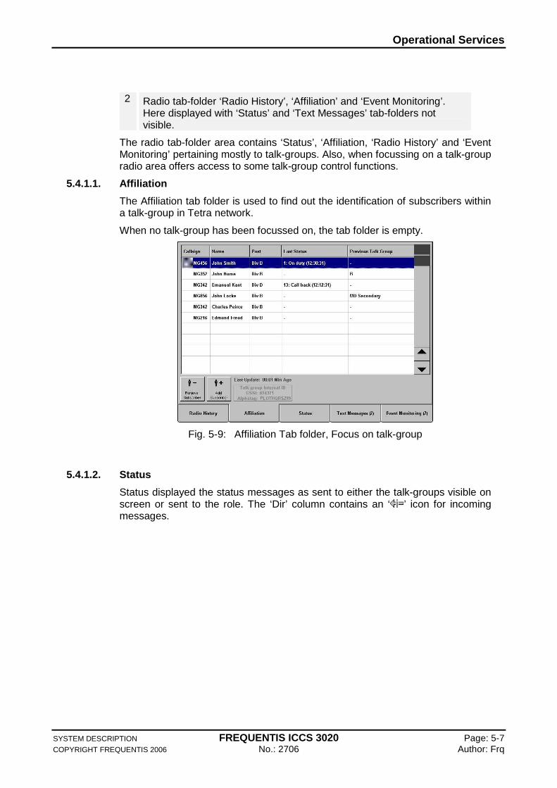
5.4.1.1. Affiliation
The Affiliation tab folder is used to find out the identification of subscribers within a talk-group in Tetra network.
When no talk-group has been focussed on, the tab folder is empty.
Fig. 5-9: Affiliation Tab folder, Focus on talk-group
5.4.1.2. Status
Status displayed the status messages as sent to either the talk-groups visible on screen or sent to the role. The ‘Dir’ column contains an ‘ ’ icon for incoming messages.
Operational Services
SYSTEM DESCRIPTION FREQUENTIS ICCS 3020 Page: 5-8 COPYRIGHT FREQUENTIS 2006 No.: 2706 Author: Frq
Fig. 5-10: Radio Status Tab Folder
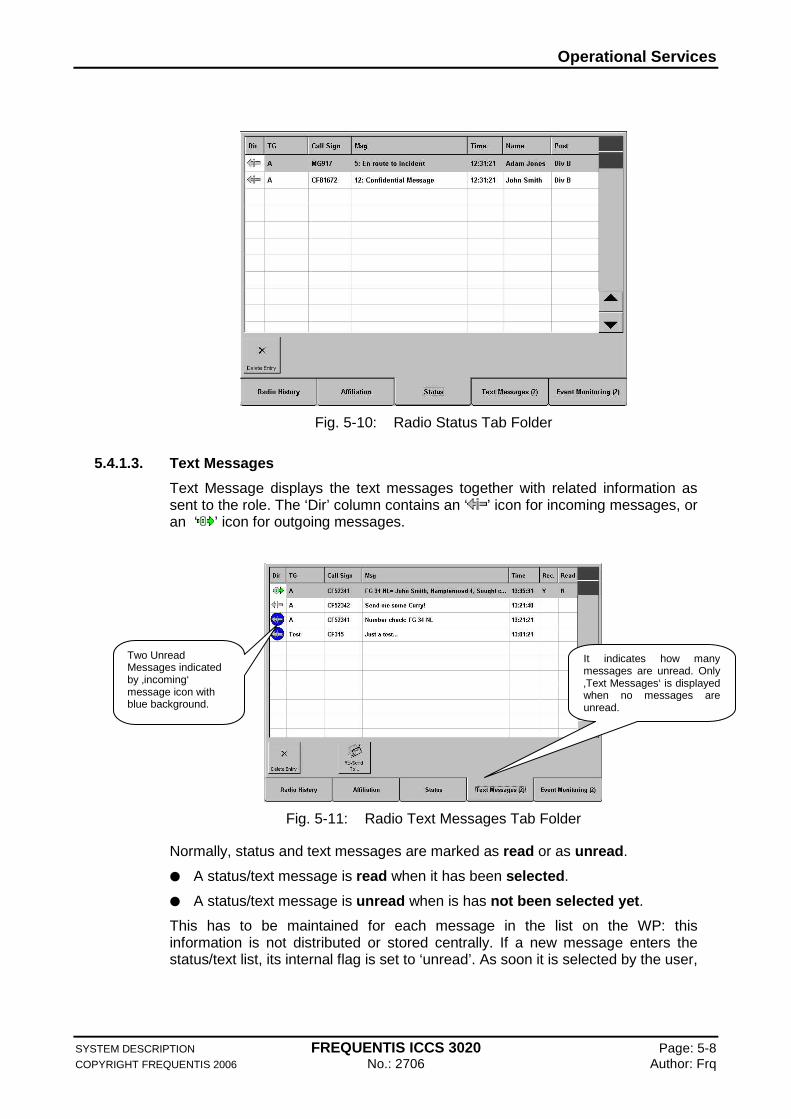
5.4.1.3. Text Messages
Text Message displays the text messages together with related information as sent to the role. The ‘Dir’ column contains an ‘ ’ icon for incoming messages, or an ‘ ’ icon for outgoing messages.
Fig. 5-11: Radio Text Messages Tab Folder
Normally, status and text messages are marked as read or as unread .
A status/text message is read when it has been selected.
A status/text message is unread when is has not been selected yet.
This has to be maintained for each message in the list on the WP: this information is not distributed or stored centrally. If a new message enters the status/text list, its internal flag is set to ‘unread’. As soon it is selected by the user,
Two Unread Messages indicated by ‚incoming‘ message icon with blue background.
It indicates how many messages are unread. Only ‚Text Messages‘ is displayed when no messages are unread.
Operational Services
SYSTEM DESCRIPTION FREQUENTIS ICCS 3020 Page: 5-9 COPYRIGHT FREQUENTIS 2006 No.: 2706 Author: Frq
this internal flag is set to ‘read’. Outgoing text messages are marked as ‘read’ automatically when sent.
The tab displays the number of unread messages.
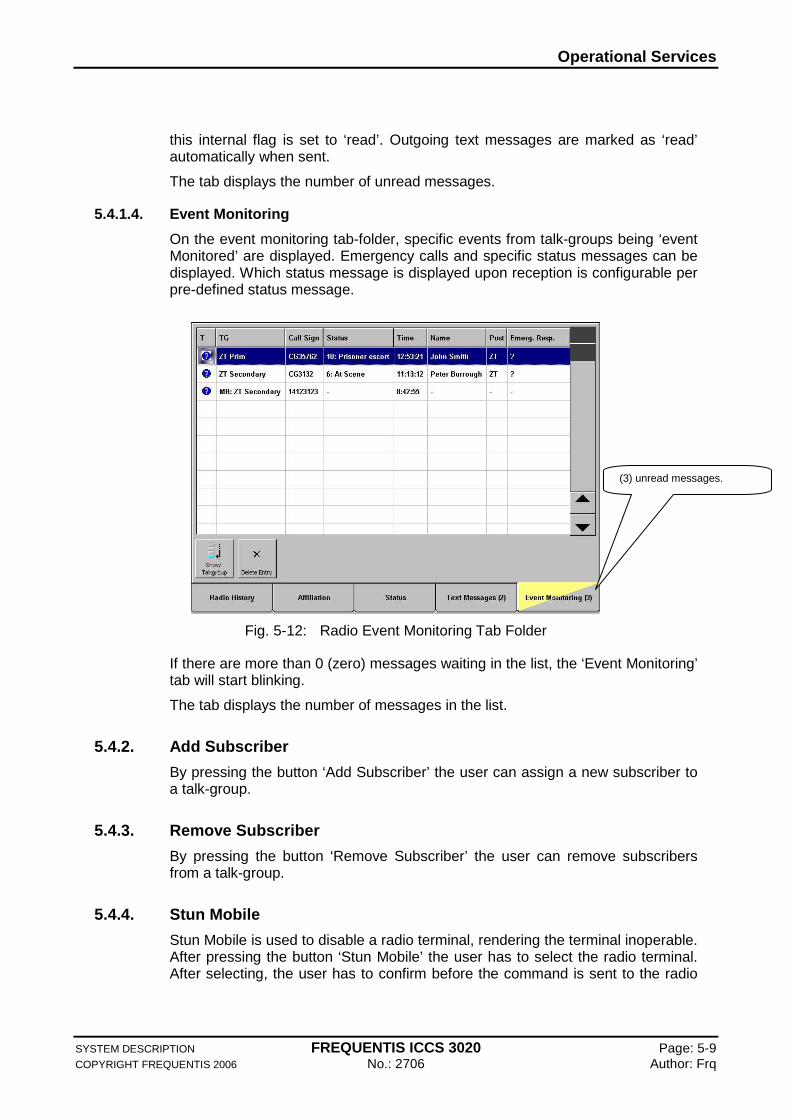
5.4.1.4. Event Monitoring
On the event monitoring tab-folder, specific events from talk-groups being ‘event Monitored’ are displayed. Emergency calls and specific status messages can be displayed. Which status message is displayed upon reception is configurable per pre-defined status message.
Fig. 5-12: Radio Event Monitoring Tab Folder
If there are more than 0 (zero) messages waiting in the list, the ‘Event Monitoring’ tab will start blinking.
The tab displays the number of messages in the list.
5.4.2. Add Subscriber
By pressing the button ‘Add Subscriber’ the user can assign a new subscriber to a talk-group.
5.4.3. Remove Subscriber
By pressing the button ‘Remove Subscriber’ the user can remove subscribers from a talk-group.
5.4.4. Stun Mobile
Stun Mobile is used to disable a radio terminal, rendering the terminal inoperable. After pressing the button ‘Stun Mobile’ the user has to select the radio terminal. After selecting, the user has to confirm before the command is sent to the radio
(3) unread messages.
Operational Services
SYSTEM DESCRIPTION FREQUENTIS ICCS 3020 Page: 5-10 COPYRIGHT FREQUENTIS 2006 No.: 2706 Author: Frq
system. The confirmation dialog includes the full identification –call sign, name, post and ISSI number- of the radio terminal to be stunned.
5.4.5. Send Alert Tone
The user can send alert tone to all talk-groups in select mode by pressing the button ‘Send alert Tone’.
The Alert tone as set in the settings page remains active until the Send Alert Tone button is released.
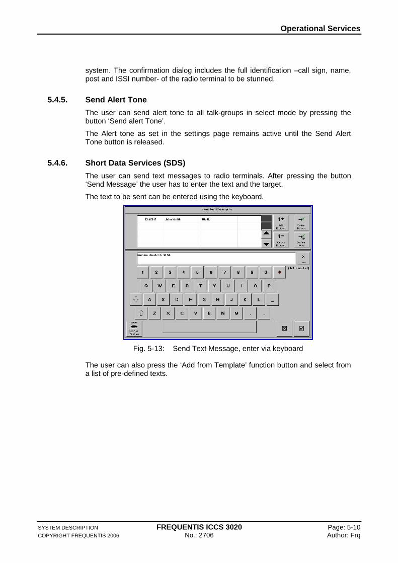
5.4.6. Short Data Services (SDS)
The user can send text messages to radio terminals. After pressing the button ‘Send Message’ the user has to enter the text and the target.
The text to be sent can be entered using the keyboard.
Fig. 5-13: Send Text Message, enter via keyboard
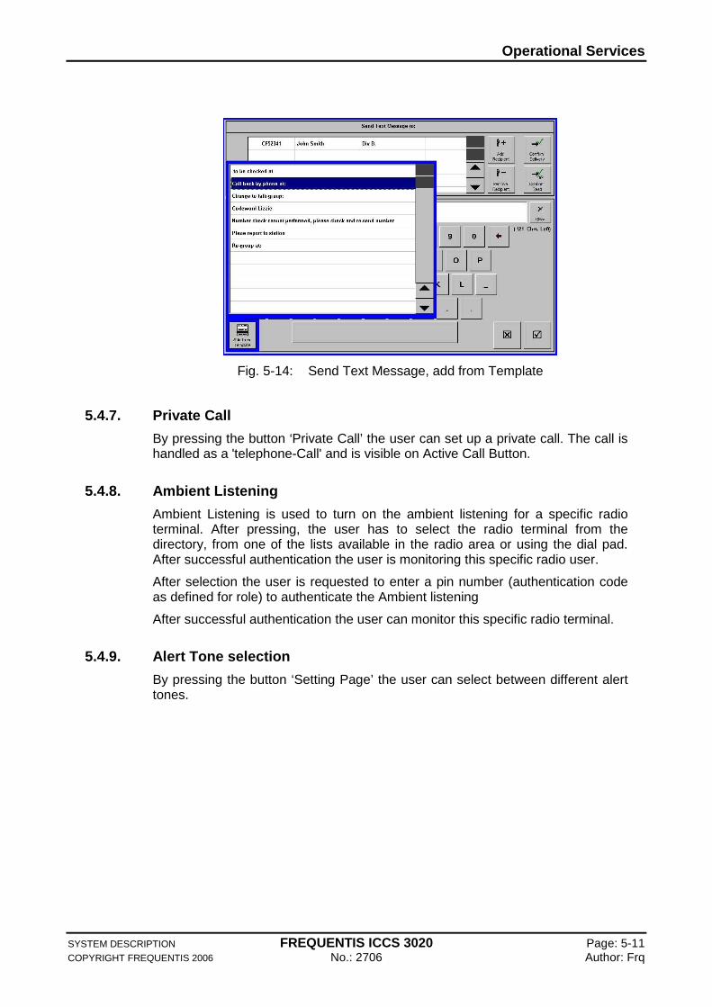
The user can also press the ‘Add from Template’ function button and select from a list of pre-defined texts.
Operational Services
SYSTEM DESCRIPTION FREQUENTIS ICCS 3020 Page: 5-11 COPYRIGHT FREQUENTIS 2006 No.: 2706 Author: Frq
Fig. 5-14: Send Text Message, add from Template
5.4.7. Private Call
By pressing the button ‘Private Call’ the user can set up a private call. The call is handled as a 'telephone-Call' and is visible on Active Call Button.
5.4.8. Ambient Listening
Ambient Listening is used to turn on the ambient listening for a specific radio terminal. After pressing, the user has to select the radio terminal from the directory, from one of the lists available in the radio area or using the dial pad. After successful authentication the user is monitoring this specific radio user.
After selection the user is requested to enter a pin number (authentication code as defined for role) to authenticate the Ambient listening
After successful authentication the user can monitor this specific radio terminal.
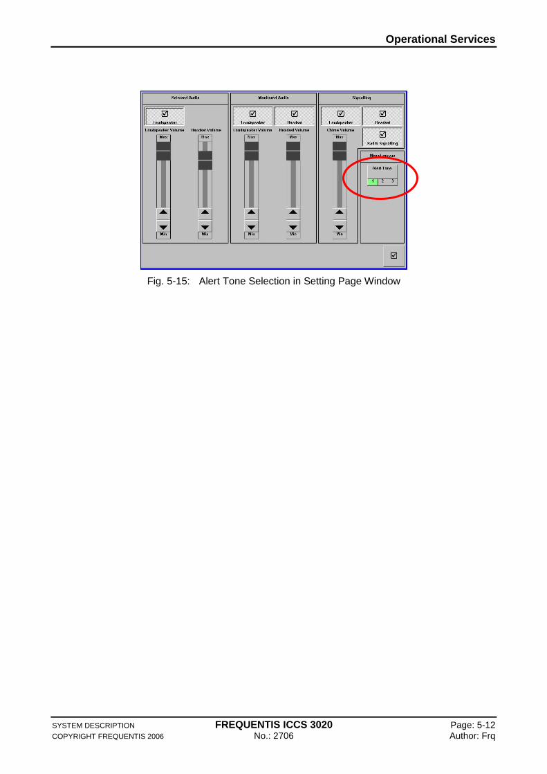
5.4.9. Alert Tone selection
By pressing the button ‘Setting Page’ the user can select between different alert tones.
Operational Services
SYSTEM DESCRIPTION FREQUENTIS ICCS 3020 Page: 5-12 COPYRIGHT FREQUENTIS 2006 No.: 2706 Author: Frq
Fig. 5-15: Alert Tone Selection in Setting Page Window
Operational Services
SYSTEM DESCRIPTION FREQUENTIS ICCS 3020 Page: 5-13 COPYRIGHT FREQUENTIS 2006 No.: 2706 Author: Frq
5.5. Supervisory Services
FREQUENTIS ICCS 3020 comes up with a lot of supervisory services.
This section describes some useful services.
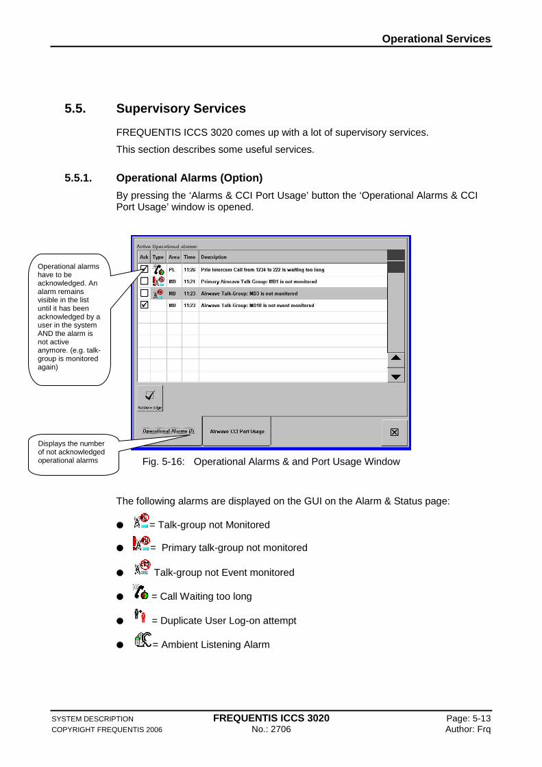
5.5.1. Operational Alarms (Option)
By pressing the ‘Alarms & CCI Port Usage’ button the ‘Operational Alarms & CCI Port Usage’ window is opened.
Fig. 5-16: Operational Alarms & and Port Usage Window
The following alarms are displayed on the GUI on the Alarm & Status page:
= Talk-group not Monitored
= Primary talk-group not monitored
Talk-group not Event monitored
= Call Waiting too long
= Duplicate User Log-on attempt
= Ambient Listening Alarm
Operational alarms have to be acknowledged. An alarm remains visible in the list until it has been acknowledged by a user in the system AND the alarm is not active anymore. (e.g. talk-group is monitored again)
Displays the number of not acknowledged operational alarms
Operational Services
SYSTEM DESCRIPTION FREQUENTIS ICCS 3020 Page: 5-14 COPYRIGHT FREQUENTIS 2006 No.: 2706 Author: Frq
5.5.2. Suggest
It is configurable per role whether the function is available to the user. If available, the user can eavesdrop on other positions (see requirement 4.8.1). The supervisor additionally has the possibility to eavesdrop and make suggestions to the eavesdropped user. The audio of the Supervisor is not audible to the radio/telephone caller.
The ‘suggest’ function offers this special function. This function is only available when the user is eavesdropping on another user. When so, pressing the function button will result in a special ‘Suggest’ intercom connection with the operator eavesdropped on. From the Supervisor point of view, s/he will have an intercom call to the operator. From the called operator point of view, it will be signalled that a supervisor is ‘eavesdropping’ on the conversation, and in the headset s/he will hear the suggestions made by the supervisor. The ‘suggest’ call is therefore a special kind of intercom call.
The ‘Suggest Call’ is only visible on the position initiating the ‘Suggest Call’ (i.e. the supervisor). The Operator being ‘suggested’ does not see on his/hers Active Call button the call, but sees that they are being monitored by the supervisor by the indication in the upper right corner of the display.
5.5.3. Intervene
It is configurable per role whether the function is available to the user. This function is only enabled when the user is eavesdropping on, or having a ‘Suggest’ call with another user. When so, pressing the function button will result in a special ‘Intervene’ intercom conference connection with the operator eavesdropped on and the calling party. From the Supervisor point of view, s/he will have an intercom call to the operator. From the called operator point of view, it will be signalled that a supervisor is ‘intervening’ on the conversation.
5.5.4. Grab Call
When a supervisor is intervening on a user having an active telephony call, after pressing this function that call is routed to the supervisor instead.
5.5.5. Eavesdrop
By pressing the ‘Eavesdrop’ button the selected entry is eavesdropped, the user gets an indication of being eavesdropped. When ‘Display Position’ is pressed, a snap-shot of current screen of the selected user is displayed, and the user is automatically eavesdropped.
On a working position only one target can be eavesdropped or covert eavesdropped on at the same time. More than 1 working position can eavesdrop or covert eavesdrop on the same target at the same time.
Only targets in a local (networked) ICCS 3020 can be eavesdropped, not targets in another ICCS 3020 not being networked to.

Operational Services
SYSTEM DESCRIPTION FREQUENTIS ICCS 3020 Page: 5-15 COPYRIGHT FREQUENTIS 2006 No.: 2706 Author: Frq
5.5.5.1. Covert Eavesdrop
By pressing the ‘Covert Eavesdrop’ button, the selected entry is eavesdropped without the user getting a indication of being eavesdropped.
5.5.5.2. End Eavesdrop
This functions ends any active eavesdrop: either ‘covert’ or ‘normal’
---------- END OF SECTION ----------
Networking and Remote Control (Option)
SYSTEM DESCRIPTION FREQUENTIS ICCS 3020 Page: 6-1 COPYRIGHT FREQUENTIS 2006 No.: 2706 Author: Frq
6. Networking and Remote Control (Option)
To achieve highest availability and in order to minimise operational costs more and more command centres are integrated with each others forming a distributed virtual command centre that allows shifting workload from one centre to the others during night time or during terror threats closure of a centre.
FREQUENTIS ICCS 3020 Systems may be linked together via high-speed network connections.
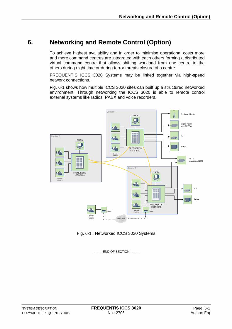
Fig. 6-1 shows how multiple ICCS 3020 sites can built up a structured networked environment. Through networking the ICCS 3020 is able to remote control external systems like radios, PABX and voice recorders.
WAN/VPN
Center 3
TMCS
Operator Positions
Center 2
TMCS
Operator Positions
Center 1
TMCS
Operator Positions
FREQUENTIS ICCS 3020
PSTN (analogue/ISDN)
Analogue Radio
Digital Radio (e.g. TETRA)
I/O
PABX
I/O
PABX
RouterRouter
Remote Operator Position
FREQUENTIS ICCS 3020
FREQUENTIS ICCS 3020
Fig. 6-1: Networked ICCS 3020 Systems
---------- END OF SECTION ----------
Role Management
SYSTEM DESCRIPTION FREQUENTIS ICCS 3020 Page: 7-1 COPYRIGHT FREQUENTIS 2006 No.: 2706 Author: Frq
7. Role Management
7.1. Role Contents
The duty of an ICCS controller or call taker relates to the communication resources he/she needs in order to fulfil his/her task. This duty is represented in the ICCS 3020 by a so-called role. A role includes the assignment of all communication resources, access rights and communication related services needed by the operator in a certain operational context.
Roles in the ICCS 3020 may consist of the following items:
Role name
Role ID (telephone ID, number under which role can be reached)
Radios and Talk groups accessible from this role
Default Radio and Talk group key layout
Radio and Talk group attributes (Coupling2 allowed, traffic mode3 allowed, permanent monitoring of radios and/or Talk groups)
Direct Access Key layout
Access rights to functions and resources (e.g. selective call barring for certain telephone numbers, )
7.2. Role Selection
In the ICCS 3020, operators can select “their” roles in accordance to the work shift directly from the working position. When a role has been selected, the operator is provided immediately with the communication resources and access rights defined for this role.
Each role is assigned to a unique role name and role ID. The role ID also represents the telephone ID for this role. As soon as the role is activated, the operator can be reached under this role ID. If the role is transferred to another position, the role ID is transferred in parallel. Therefore true free seating is enabled because configuration set-ups are not bound to a certain physical position.
Role selections can be performed without the intervention of a supervisor. This, in turn allows for quick and easy position changes in case of position failures or the need for quick opening of new positions.
7.3. User Profiles
Security and user authorisation is not only an issue for military applications. Like any computer network, countrywide public safety communication networks must
2 Interconnection of radios or Talk groups (combine) 3 also referred as TX mode
Role Management
SYSTEM DESCRIPTION FREQUENTIS ICCS 3020 Page: 7-2 COPYRIGHT FREQUENTIS 2006 No.: 2706 Author: Frq
control access to several system services and personalise the environment for individual users. The ICCS 3020 user profiles provide comfortable and secure means to meet this demand.
User Login and Password Control
The access to the ICCS 3020 communication services can be restricted to authorised personnel by entering a user name and password at the working position. The management system keeps a log of the login procedure. The ICCS 3020 is set up to use directory services like Microsoft Active Directory for user authentication.
Role Access Rights
In accordance to the access rights configured for a certain user, user access can be restricted to only a subset of the available roles. This feature is especially important for the decentralised hand-over of roles in distributed, networked systems, performed directly by the operators. Only operators with appropriate authorisation are to be enabled to remotely select specific roles. This authorisation is guaranteed by the user profile.
---------- END OF SECTION ----------
Interfaces
SYSTEM DESCRIPTION FREQUENTIS ICCS 3020 Page: 8-1 COPYRIGHT FREQUENTIS 2006 No.: 2706 Author: Frq
8. Interfaces
The FREQUENTIS ICCS 3020 provides an extensive range of radio, telephone, data and network interfacing capability providing simple configuration for multiple, site specific interface types. The system can be directly connected to a wide range of communication equipment. Also special signalling protocols (e.g. for remote control) are available.
8.1. Analogue Radio (Option)
2 analogue channels, each with Rx / Tx / Squelch / PTT
Remote control signalling can be performed using inband, outband, Phantom or E&M signalling or by using RS 232/ RS 485 connectors to the radios.
8.2. Analogue Telephone
Central office line interface, 2-wire (connection of a telephone set with DTMF or pulse dialling) conforming with ITU-T Q.23
PABX/PSTN line interface, 2-wire (connection to an analogue PSTN exchange or a PABX system)
Voice call interface (announcement signalling)
AC 15 A British Telecom selective signalling acc. BTNR 181 (Option)
SS1/SS3/SS4 selective trunk types (Option)
8.3. Digital Trunked Radio (Option)
FREQUENTIS ICCS 3020 provides TETRA Interfaces in according to ETSI standard.
FREQUENTIS is a TETRA pioneer. Our engagement with TETRA dates back to the early nineties. Since then we have become an important partner for the development of TETRA solutions. We are a reliable technology partner in all areas of TETRA infrastructure development – starting from the design and development of central systems complete with switches, HF areas, network management and subscriber management systems to customer-specific dispatcher solutions. Our customers profit from our long lasting experience, our broad range of applications and products, our comprehensive service portfolio, as well as from our partnerships with some of the world’s largest TETRA manufacturers.
Additionally, with eXTRAS FREQUENTIS offers its customers the possibility to access solutions of the TETRA market more profitably. eXTRAS is a TETRA system based completely on FREQUENTIS software development using COTS (Commercial Off The Shelf) hardware wherever appropriate.
Interfaces
SYSTEM DESCRIPTION FREQUENTIS ICCS 3020 Page: 8-2 COPYRIGHT FREQUENTIS 2006 No.: 2706 Author: Frq
8.4. Digital Telephone
FREQUENTIS ICCS 3020 provides comprehensive interface capabilities to nearly every kind of digital telephone interfaces and protocols like:
QSIG
DPNSS
ISDN BRI 2B+D
ISDN PRI 30B+D
8.5. Digital I/O
The digital I/O interfaces are used for general remote control purposes and for fault detection that falls outside the internal ICCS 3020 diagnostics capability (for example the fan unit supervision or to control the door or lamp). External alarm conditions may also be included where compatibility with the alarm interface exists. The digital I/O interfaces are housed in a standard interface rack.
Relay Output Interface
The relay output interface provides relay contacts configurable for dry contact/ground/DC and opto-isolated inputs.
Opto-isolated Input Interface
The opto-isolated input interface card provides opto-isolated inputs and relay outputs. These interfaces are used to serve additional control functions, such as door release or light control.
8.6. Serial Data Interfaces (Option)
The FREQUENTIS ICCS 3020 provides serial data interfaces, which can be configured for either RS 232 or RS 422. The serial data interfaces can also be used to connect radio equipment to the ICCS 3020 system for radio remote control purposes.
8.7. Recording Interfaces
FREQUENTIS ICCS 3020 provides recording interfaces for the recording of working position audio and radio channel/telephone line audio:
Working Position Recording
An analogue recording output is available at the PCCTI analogue audio interface.
Digital 2 MBit/s E1 recording outputs are located at the core system for central recording of all working positions (for connection to multi channel recorders)

Interfaces
SYSTEM DESCRIPTION FREQUENTIS ICCS 3020 Page: 8-3 COPYRIGHT FREQUENTIS 2006 No.: 2706 Author: Frq
Line Recording
Analogue and digital recording outputs for individual radio channel and telephone line recording are available either directly at the line interface cards or as combined 2 MBit/s E1 recording links at the core system.
8.8. Network Interfaces (Option)
The network interface unit holds the network interfaces, allowing the ICCS 3020 to interface with other ICCS systems that are distributed in a network, using a point- to-point connection or using on-demand-connection establishment.
---------- END OF SECTION ----------
Technical Monitoring and Control System
SYSTEM DESCRIPTION FREQUENTIS ICCS 3020 Page: 9-1 COPYRIGHT FREQUENTIS 2006 No.: 2706 Author: Frq
9. Technical Monitoring and Control System
The management system TMCS is the technical monitoring and control system for the FREQUENTIS ICCS 3020.
Once the TMCS has been installed and the FREQUENTIS ICCS 3020 has been configured, the TMCS doesn't necessarily have to be connected online to the system. Neither the TMCS, nor the FREQUENTIS ICCS 3020 gateway is required for the normal operation of the system. Online connection of the TMCS is required for system configuration, continuous status monitoring and event logging, as well as for software downloads to components (e.g. in case of board exchange). The TMCS consists of two main parts:
Parameter Editor (PE) - for parameter changes and download to system
Element Management System (ELMAS) - for monitoring of system status
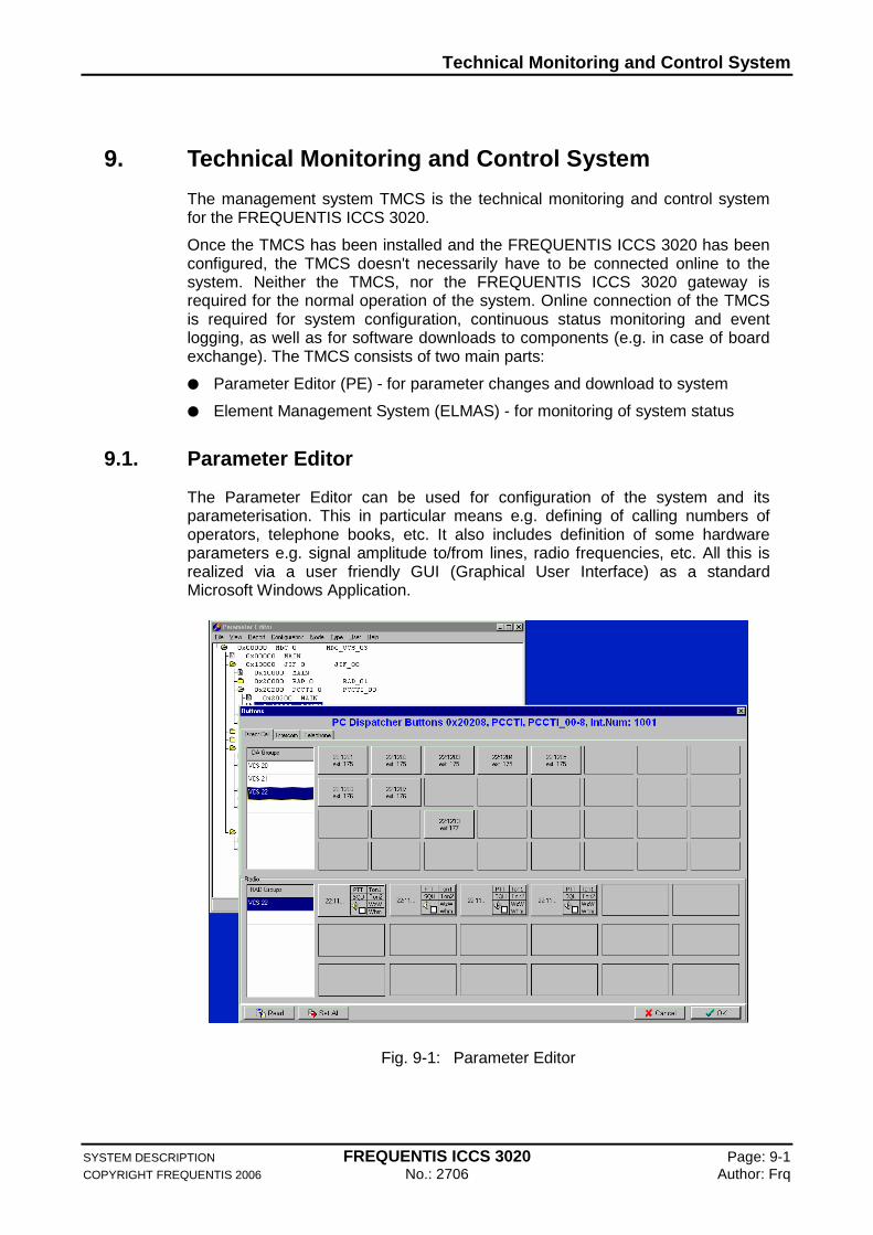
9.1. Parameter Editor
The Parameter Editor can be used for configuration of the system and its parameterisation. This in particular means e.g. defining of calling numbers of operators, telephone books, etc. It also includes definition of some hardware parameters e.g. signal amplitude to/from lines, radio frequencies, etc. All this is realized via a user friendly GUI (Graphical User Interface) as a standard Microsoft Windows Application.
Fig. 9-1: Parameter Editor
Technical Monitoring and Control System
SYSTEM DESCRIPTION FREQUENTIS ICCS 3020 Page: 9-2 COPYRIGHT FREQUENTIS 2006 No.: 2706 Author: Frq
The GUI offers an overview of all hardware devices in the system. Some devices are configured by system specialists during system installation; others are configurable by the user.
The parameter editor communicates with ICCS 3020. It is a part of the TMCS PC, depicts the communication. The steps are:
1. The user modifies parameters in the database. Example: a user changes the layout of the DA buttons and changes some settings of telephone line 1.
2. The user uploads the modified parameters and settings from ICCS 3020.
3. Depending on the type of parameters they are either automatically activated or upon user confirmation. An example for automatic confirmation is a telephone interface that does not have a call: The parameters are activated while the board is not in use. Another example is the parameters for the PC in Working Position: If new parameters are available, the user gets an indication and can decide when the new parameters are activated.
9.2. ELMAS
The Element Management System (ELMAS) gives system engineers an overview of the ICCS 3020 system status. ELMAS offers a view of the system with each device having a colour icon representing its state:
Green: OK
Red: failure
Blinking Green: state changing
Yellow: reporting is turned off
More details about the status of a particular device are available, if the user selects it. These details then help to evaluate the severity of the problem (e.g. disconnected line, failed board, etc.).
The devices themselves also run independent tests, without interfering with normal tasks, and report their results to ELMAS. The ELMAS automatically generates alarms with different priorities for the user:
Minor alarm
Major alarm
Critical alarm
They are stored in the database, together with their timestamp, and can be analysed at any time.
The ELMAS offers two basic views on the system:
Cabinet view (insert a fig.)
Tree view (insert a fig.)
Technical Monitoring and Control System
SYSTEM DESCRIPTION FREQUENTIS ICCS 3020 Page: 9-3 COPYRIGHT FREQUENTIS 2006 No.: 2706 Author: Frq
The cabinet view shows all boards with their states in their positions as they are in the system cabinet. In the tree view the devices are logically connected, according to the system architecture, which enables easier tracing of errors over more devices. Each system part is shown in green to indicate that it is OK, or in red in case of failure. The user has also an overview over state changes (e.g. if a board was OK, failed for 5 minutes and is again OK it will be blinking Green), and he must confirm these state changes (it stops blinking afterwards). The user also has possibility to turn off reporting of errors for some particular device (device is then shown in Yellow colour). In this way, different colours help users to quickly identify the problem.
9.2.1. Logging of ICCS 3020 Status and Error Events
All fault reports are annotated with the time and date of their occurrence and a unique fault identifier. A record log of all these faults is created by ELMAS. The user has a possibility to view the current log, as well as the history of the logs. This can help to identify the errors, which occur only seldom.
9.2.2. Interconnected ICCS 3020 Sites have Common S tate Reporting
If there are more ICCS 3020 sites, which are interconnected, ELMAS is able to display statuses of all these sites. Basically there can be an ELMAS in each site, which is able to display the status of all ICCS 3020 systems connected to network.
9.2.3. Interface to ELMAS Database
A Database is used to store ELMAS logging and statistical data. FREQUENTIS provides an easy to use interface to this database to generate customer specific reports.
9.2.4. SNMP Interface
ELMAS provides an SNMP (Simple Network Management Protocol) interface to allow to integrate the ICCS 3020 to an umbrella management system or to integrate several other SNMP enabled components into the ELMAS system.
---------- END OF SECTION ----------
External Systems
SYSTEM DESCRIPTION FREQUENTIS ICCS 3020 Page: 10-1 COPYRIGHT FREQUENTIS 2006 No.: 2706 Author: Frq
10. External Systems
This section explains the utilization of the external system for the users.
10.1. External Clock
The system internal clock may be synchronized to external time sources like GPS, Rugby Time, and DCF77 or via the network with NTP. The NTP is used to synchronize the time of the ICCS 3020 system to another reference time sources.
The system clock uses internally only UTC time and calculates the local time. Specific reports given for third party application are in UTC.
10.2. Legal Voice Recording (Option)
Voice recording systems are typically connected either via analogue lines or digital 2 MBit/s E1 lines. Line recording can be performed centrally from the core switch or directly from the line interfaces. Voice recording at the working positions is either possible through separate time slots directly from the core switch, or through a direct connection at the working position. Recorder control (i.e. channel selection and replay) may be performed via the GUI of the working position. The ICCS 3020 can provide caller ID information and time synchronisation for each voice channel to be recorded.
For short time recording the ICCS 3020 provides an integrated software-based recording feature with a 30-minute capacity (voice/no silence) at each working position. The short time recording feature requires no central equipment.
External Systems
SYSTEM DESCRIPTION FREQUENTIS ICCS 3020 Page: 10-2 COPYRIGHT FREQUENTIS 2006 No.: 2706 Author: Frq
10.3. CAD.NET
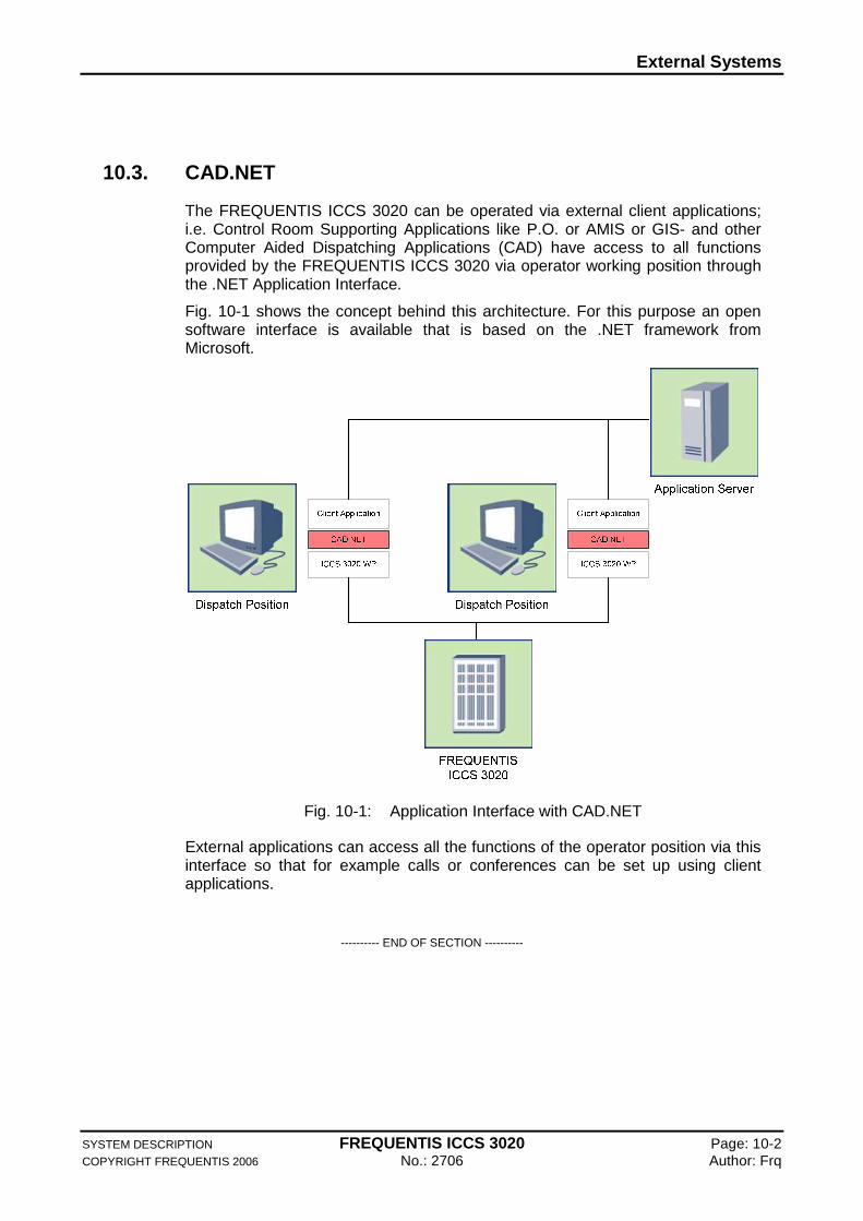
The FREQUENTIS ICCS 3020 can be operated via external client applications; i.e. Control Room Supporting Applications like P.O. or AMIS or GIS- and other Computer Aided Dispatching Applications (CAD) have access to all functions provided by the FREQUENTIS ICCS 3020 via operator working position through the .NET Application Interface.
Fig. 10-1 shows the concept behind this architecture. For this purpose an open software interface is available that is based on the .NET framework from Microsoft.
Fig. 10-1: Application Interface with CAD.NET
External applications can access all the functions of the operator position via this interface so that for example calls or conferences can be set up using client applications.
---------- END OF SECTION ----------
Technical Specifications
SYSTEM DESCRIPTION FREQUENTIS ICCS 3020 Page: 11-1 COPYRIGHT FREQUENTIS 2006 No.: 2706 Author: Frq
11. Technical Specifications
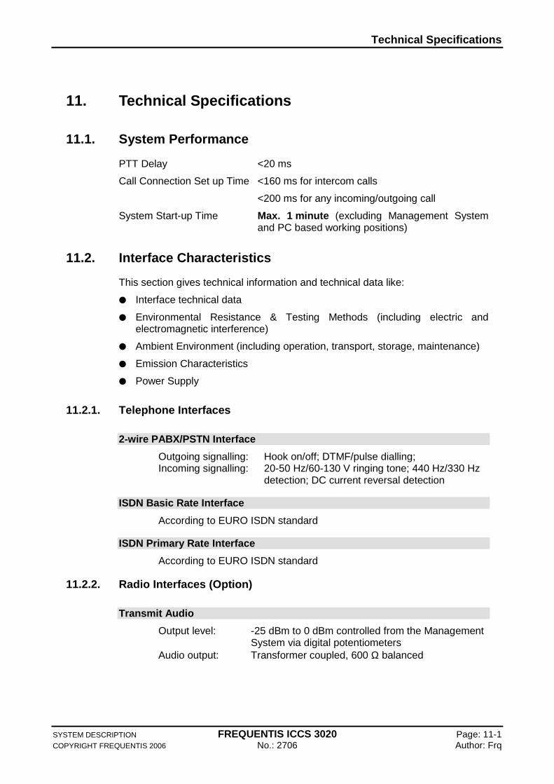
11.1. System Performance
PTT Delay <20 ms
Call Connection Set up Time <160 ms for intercom calls
<200 ms for any incoming/outgoing call
System Start-up Time Max. 1 minute (excluding Management System and PC based working positions)
11.2. Interface Characteristics
This section gives technical information and technical data like:
Interface technical data
Environmental Resistance & Testing Methods (including electric and electromagnetic interference)
Ambient Environment (including operation, transport, storage, maintenance)
Emission Characteristics
Power Supply
11.2.1. Telephone Interfaces
2-wire PABX/PSTN Interface
Outgoing signalling: Hook on/off; DTMF/pulse dialling; Incoming signalling: 20-50 Hz/60-130 V ringing tone; 440 Hz/330 Hz
detection; DC current reversal detection
ISDN Basic Rate Interface
According to EURO ISDN standard
ISDN Primary Rate Interface
According to EURO ISDN standard
11.2.2. Radio Interfaces (Option)
Transmit Audio
Output level: -25 dBm to 0 dBm controlled from the Management System via digital potentiometers
Audio output: Transformer coupled, 600 Ω balanced
Technical Specifications
SYSTEM DESCRIPTION FREQUENTIS ICCS 3020 Page: 11-2 COPYRIGHT FREQUENTIS 2006 No.: 2706 Author: Frq
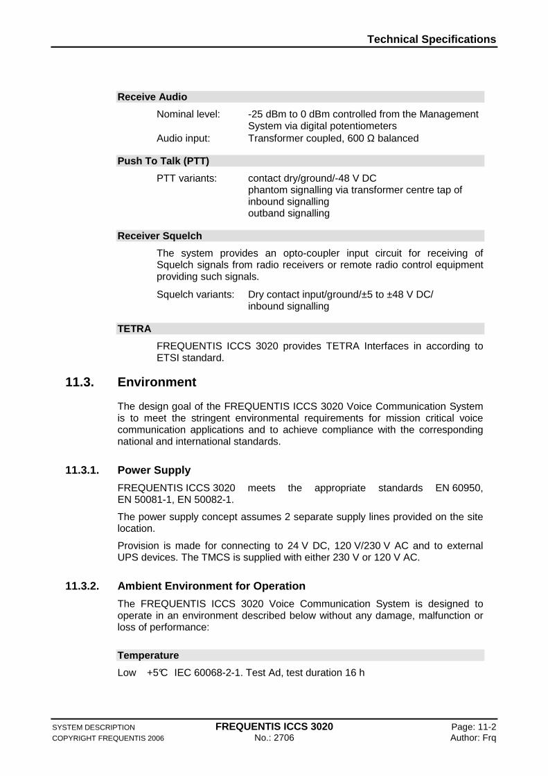
Receive Audio
Nominal level: -25 dBm to 0 dBm controlled from the Management System via digital potentiometers
Audio input: Transformer coupled, 600 Ω balanced
Push To Talk (PTT)
PTT variants: contact dry/ground/-48 V DC phantom signalling via transformer centre tap of inbound signalling
outband signalling
Receiver Squelch
The system provides an opto-coupler input circuit for receiving of Squelch signals from radio receivers or remote radio control equipment providing such signals.
Squelch variants: Dry contact input/ground/±5 to ±48 V DC/ inbound signalling
TETRA
FREQUENTIS ICCS 3020 provides TETRA Interfaces in according to ETSI standard.
11.3. Environment
The design goal of the FREQUENTIS ICCS 3020 Voice Communication System is to meet the stringent environmental requirements for mission critical voice communication applications and to achieve compliance with the corresponding national and international standards.
11.3.1. Power Supply
FREQUENTIS ICCS 3020 meets the appropriate standards EN 60950, EN 50081-1, EN 50082-1.
The power supply concept assumes 2 separate supply lines provided on the site location.
Provision is made for connecting to 24 V DC, 120 V/230 V AC and to external UPS devices. The TMCS is supplied with either 230 V or 120 V AC.
11.3.2. Ambient Environment for Operation
The FREQUENTIS ICCS 3020 Voice Communication System is designed to operate in an environment described below without any damage, malfunction or loss of performance:
Temperature
Low +5°C IEC 60068-2-1. Test Ad, test duration 16 h
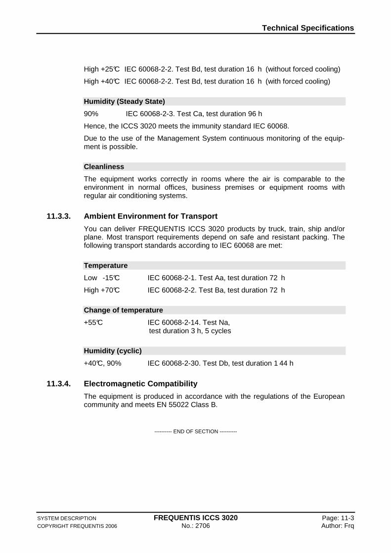
Technical Specifications
SYSTEM DESCRIPTION FREQUENTIS ICCS 3020 Page: 11-3 COPYRIGHT FREQUENTIS 2006 No.: 2706 Author: Frq
High +25°C IEC 60068-2-2. Test Bd, test duration 16 h (without forced cooling)
High +40°C IEC 60068-2-2. Test Bd, test duration 16 h (with forced cooling)
Humidity (Steady State)
90% IEC 60068-2-3. Test Ca, test duration 96 h
Hence, the ICCS 3020 meets the immunity standard IEC 60068.
Due to the use of the Management System continuous monitoring of the equip-ment is possible.
Cleanliness
The equipment works correctly in rooms where the air is comparable to the environment in normal offices, business premises or equipment rooms with regular air conditioning systems.
11.3.3. Ambient Environment for Transport
You can deliver FREQUENTIS ICCS 3020 products by truck, train, ship and/or plane. Most transport requirements depend on safe and resistant packing. The following transport standards according to IEC 60068 are met:
Temperature
Low -15°C IEC 60068-2-1. Test Aa, test duration 72 h
High +70°C IEC 60068-2-2. Test Ba, test duration 72 h
Change of temperature
+55°C IEC 60068-2-14. Test Na, test duration 3 h, 5 cycles
Humidity (cyclic)
+40°C, 90% IEC 60068-2-30. Test Db, test duration 1 44 h
11.3.4. Electromagnetic Compatibility
The equipment is produced in accordance with the regulations of the European community and meets EN 55022 Class B.
---------- END OF SECTION ----------

Abbreviations and Acronyms
SYSTEM DESCRIPTION FREQUENTIS ICCS 3020 Page: 12-1 COPYRIGHT FREQUENTIS 2006 No.: 2706 Author: Frq
12. Abbreviations and Acronyms
This section contains an alphabetical list of all abbreviations/acronyms used in the Product Description.
ACD Automatic Call Distribution
BITE Comprehensive Built In Test Equipment
C&C Command and Control
CAD Computer Aided Dispatching
CCI Communications Control Interface
CLIP Calling Line Identification Party
COTS Commercial Off The Shelf
ELMAS Element Management System
GUI Graphical User Interface
ICCS Integrated Command and Control System
ISDN Integrated Services Digital Network
ISDN-BRI ISDN Basic Rate
ISDN-PRI ISDN Primary Rate
NTP Network Time Protocol
PCM Pulse Code Modulation
PE Parameter Editor
SDS Short Data Service
SNMP Simple Network Management Protocol
TDMA Time-Division Multiple Access
TETRA Terrestrial Trunked Radio
TMCS Technical Monitoring and Control System
UTC Coordinated Universal Time
WP Operator Working Position
---------- END OF SECTION ----------
Related Documents