E500 SERIES E XPANSIVE F UNCTIONALITY IN A C OMPACT P ACKAGE VARIABLE FREQUENCY DRIVES

Welcome message from author
This document is posted to help you gain knowledge. Please leave a comment to let me know what you think about it! Share it to your friends and learn new things together.
Transcript
E500 SERIES
EXPANSIVE FUNCTIONALITY INA COMPACT PACKAGE
VARIABLE FREQUENCY DRIVES

Mitsubishi’s New E500 SeriesOffers Three Great Values.
POWERFUL
SIMPLE
Get a high torque (150%) at speeds as low as 1HzA regenerative braking resistor can beconnected (0.4K or more)The high response current limit function helps provide safetyNow with an even higher output current rating
The control panel now has a frequency setting knob as standard equipment.
Easy to operate.
Easy access make the cooling fan easy to replace.Easy to maintain.
Screwed terminal plates are used for the main circuit and for the control circuit (leads plug in).
Wiring is simple.
1
NATIONALACCREDITATION
OF CERTIFICATIONBODIES
ORGANIZATION
FOR
ENVIRONMENT•JAPAN
AUDIT
AN
DC
ERTI
FICATION
SMALLOnly 85% the volume of a Mitsubishi FREQROL-U100 (for FR-E520-0.2K).
Most compact inverter in its class.
All models from 0.1 to 3.7kW are the same 128mm in height making panel layout easier. (Except FR-E540)
Height is now standardized.
Contents
Features 3
Networks 6
Model Configurations 7
Standard Specifications 8
External Dimension Diagrams and 10 Terminal Layouts
Terminal Connection Diagram 12
Description of Terminal Specifications 13
Operation 14
List of Parameters 15
Description of Parameters 18
Protective Functions 29
Connection Examples 30
Peripherals 32
Optional Equipment 34
Characteristic Data 39
Motor Applications 40
Cautions 41
2
Features
3
–300
–200
–100
30 90180 300 600 900 1200 1500 1800
Rotation speed(r/min)
Tor
que
(%)
0
100
200
300
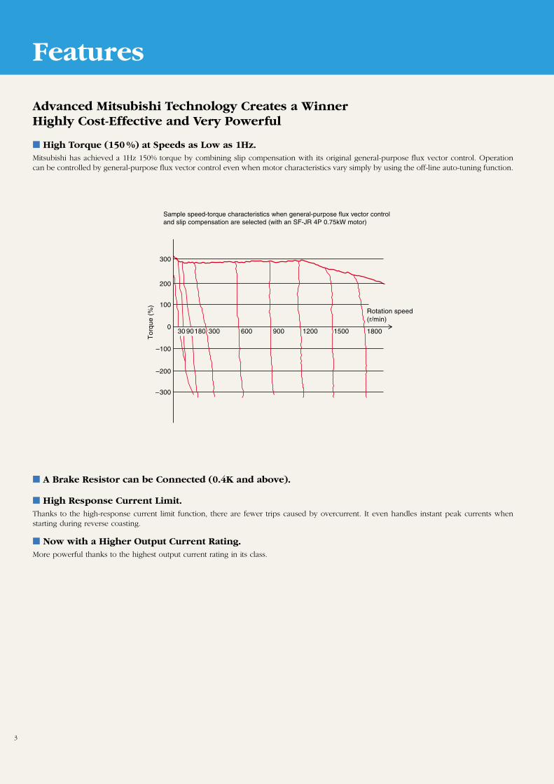
High Torque (150 %) at Speeds as Low as 1Hz.Mitsubishi has achieved a 1Hz 150% torque by combining slip compensation with its original general-purpose flux vector control. Operationcan be controlled by general-purpose flux vector control even when motor characteristics vary simply by using the off-line auto-tuning function.
A Brake Resistor can be Connected (0.4K and above).
High Response Current Limit.Thanks to the high-response current limit function, there are fewer trips caused by overcurrent. It even handles instant peak currents whenstarting during reverse coasting.
Now with a Higher Output Current Rating.More powerful thanks to the highest output current rating in its class.
Sample speed-torque characteristics when general-purpose flux vector controland slip compensation are selected (with an SF-JR 4P 0.75kW motor)
Advanced Mitsubishi Technology Creates a WinnerHighly Cost-Effective and Very Powerful
Features
4
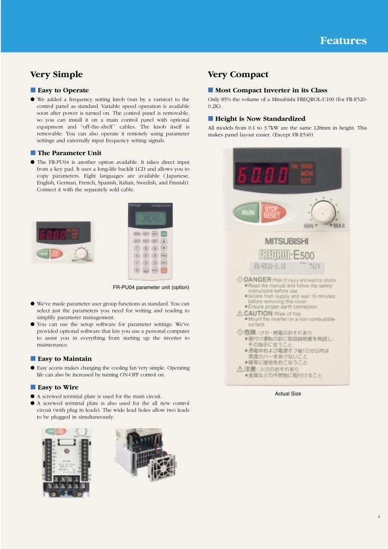
FR-PU04 parameter unit (option)
Actual Size
Easy to Operate We added a frequency setting knob (run by a varistor) to the
control panel as standard. Variable speed operation is availablesoon after power is turned on. The control panel is removable,so you can install it on a main control panel with optionalequipment and “off-the-shelf ” cables. The knob itself isremovable. You can also operate it remotely using parametersettings and externally input frequency setting signals.
The Parameter Unit The FR-PU04 is another option available. It takes direct input
from a key pad. It uses a long-life backlit LCD and allows you tocopy parameters. Eight languages are available ( Japanese,English, German, French, Spanish, Italian, Swedish, and Finnish).Connect it with the separately sold cable.
We've made parameter user group functions as standard. You canselect just the parameters you need for writing and reading tosimplify parameter management.
You can use the setup software for parameter settings. We'veprovided optional software that lets you use a personal computerto assist you in everything from starting up the inverter tomaintenance.
Very Simple
Most Compact Inverter in its ClassOnly 85% the volume of a Mitsubishi FREQROL-U100 (for FR-E520-0.2K).
Height is Now StandardizedAll models from 0.1 to 3.7kW are the same 128mm in height. Thismakes panel layout easier. (Except FR-E540)
Very Compact
Easy to Maintain Easy access makes changing the cooling fan very simple. Operating
life can also be increased by turning ON-OFF control on.
Easy to Wire A screwed terminal plate is used for the main circuit. A screwed terminal plate is also used for the all new control
circuit (with plug in leads). The wide lead holes allow two leadsto be plugged in simultaneously.
Features
5
Newly Developed Soft-PWM Control
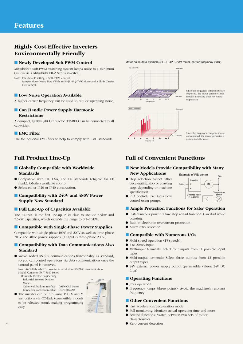
Mitsubishi’s Soft-PWM switching system keeps noise to a minimum(as low as a Mitsubishi FR-Z Series inverter).
Note: The default setting is Soft-PWM control.Sample Motor Noise Data (With an SF-JR 4P 3.7kW Motor and a 2kHz CarrierFrequency).
Highly Cost-Effective InvertersEnvironmentally Friendly
Low Noise Operation AvailableA higher carrier frequency can be used to reduce operating noise.
Can Handle Power Supply HarmonicRestrictions
A compact, lightweight DC reactor (FR-BEL) can be connected to allcapacities.
EMC FilterUse the optional EMC filter to help to comply with EMC standards.
Motor noise data example (SF-JR 4P 3.7kW motor, carrier frequency 2kHz)
Noise level
Frequency (Hz)
0 2k 4k 6k 8k 10k 12k 0
2
4
Time (sec)
With Soft-PWM
0 2k 4k 6k 8k 10k 12k 0
4
0 2k 4k 6k 8k 10k 12k 0
2
Frequency (Hz)
Noise level
Time (sec)
Without Soft-PWM
Since the frequency components aredispersed, the motor generates littlemetallic noise and does not soundunpleasant.
Since the frequency components areconcentrated, the motor generates agrating metallic noise.
Globally Compatible with WorldwideStandards
Compatible with UL, CSA, and EN standards (eligible for CEmark). (Models available soon.)
Select either IP20 or IP40 construction.
Compatibility with 240V and 480V PowerSupply Now Standard
Full Line-Up of Capacities AvailableThe FR-E500 is the first line-up in its class to include 5.5kW and7.5kW capacities, which extends the range to 0.1–7.5kW.
Compatible with Single-Phase Power SuppliesCompatible with single phase 100V and 200V as well as three-phase200V and 400V power supplies. (Output is three-phase 200V.)
Compatibility with Data Communications AlsoStandard
We've added RS-485 communications functionality as standard,so you can control operations via data communications once thecontrol panel is removed.Note: An “off-the-shelf” converter is needed for RS-232C communication.Model: Converter FA-T-RS40 Series
Mitsubishi Electric EngineeringIndustrial Systems DivisionModel:Cable with built-in interface DAFX-CAB SeriesConnector conversion cable DINV-485CAB
The inverter can be run using PLC X and Yinstructions via CC-Link (compatible modelsto be released soon), making programmingeasy.
Full Product Line-Up
New Models Provide Compatibility with ManyNew Applications
Stop selection: Select eitherdecelerating stop or coastingstop, depending on machinespecification
PID control: Facilitates flowcontrol using pumps.
Ample Protection Functions for Safer Operation Instantaneous power failure stop restart function: Can start while
coasting. Built-in electronic overcurrent protection Alarm retry selection
Compatible with Numerous I/Os Multi-speed operation (15 speeds) 4 to 20mA input Multi-input terminals: Select four inputs from 11 possible input
types Multi-output terminals: Select three outputs from 12 possible
output types 24V external power supply output (permissible values: 24V DC
0.1A)
Operating Functions JOG operation Frequency jumps (three points): Avoid the machine’s resonant
frequency
Other Convenient Functions Fast acceleration/deceleration mode Full monitoring: Monitors actual operating time and more Second functions: Switch between two sets of motor
characteristics Zero current detection
Full of Convenient Functions
Inverter
2
4
Example of PID control
Setting IM
Fan
Detected value(4 to 20mA)
Temperaturesensor
Networks
6
Inverter Setup SoftwareFR-SW0-SETUP-WJ (Windows* 3.1 or 95) ( Japanese)
FR-SW0-SETUP-WE (Windows* 3.1 or 95) (English)
Inverter setup software provides an amenable inverter operatingenvironment. Use it as a support tool for everything from inverterstartup to maintenance. It allows you to efficiently set parametersand motor operation in Windows*.*"Windows" is a registered trademark of Microsoft Corporation.Note: Some models will soon be compatible.
Functions Set and edit parameters Monitor Test operation Diagnosis System settings Files Windows Help
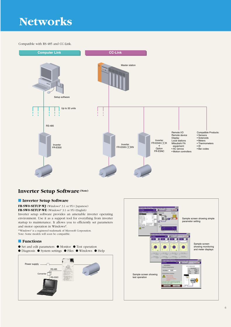
Inverter Setup Software (Note)
Computer Link
InverterFR-E500
Setup software
Master station
RS-485
Up to 32 units
CC-Link
InverterFR-E500- KN
InverterFR-E540- K
+Option
FR-E5NC
Remote I/ORemote deviceDisplayLocal stationsMitsubishi FA equipment:• AC servos• Motion controllers
Compatible Products:• Sensors• Solenoids• Meters• Thermometers• ID• Bar codes
RS-485
RS-232C
Converter
Compatible with RS-485 and CC-Link.
Power supply
Sample screen showing simpleparameter setting
Sample screenshowing monitoringand meter displays
Sample screen showingtest operation
7
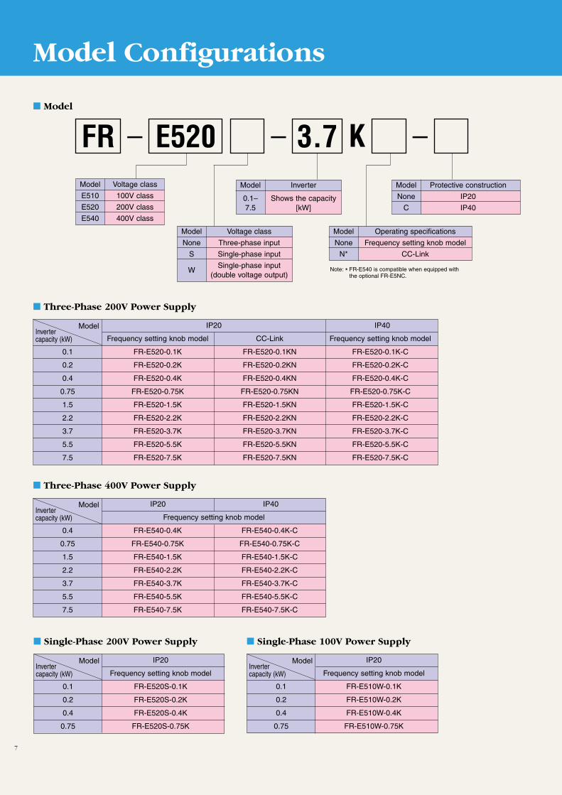
Model Configurations
Three-Phase 200V Power Supply
Model
Model Voltage class
E510 100V class
E520 200V class
E540 400V class
IP20 IP40
Frequency setting knob model CC-Link Frequency setting knob model
0.1 FR-E520-0.1K FR-E520-0.1KN FR-E520-0.1K-C
0.2 FR-E520-0.2K FR-E520-0.2KN FR-E520-0.2K-C
0.4 FR-E520-0.4K FR-E520-0.4KN FR-E520-0.4K-C
0.75 FR-E520-0.75K FR-E520-0.75KN FR-E520-0.75K-C
1.5 FR-E520-1.5K FR-E520-1.5KN FR-E520-1.5K-C
2.2 FR-E520-2.2K FR-E520-2.2KN FR-E520-2.2K-C
3.7 FR-E520-3.7K FR-E520-3.7KN FR-E520-3.7K-C
5.5 FR-E520-5.5K FR-E520-5.5KN FR-E520-5.5K-C
7.5 FR-E520-7.5K FR-E520-7.5KN FR-E520-7.5K-C
Model Voltage class
None Three-phase input
S Single-phase input
WSingle-phase input
(double voltage output)
Model Protective construction
None IP20
C IP40
Model Inverter
0.1– Shows the capacity 7.5 [kW]
_ _ K _3.7E520FR
Model Operating specifications
None Frequency setting knob model
N* CC-Link
ModelInvertercapacity (kW)
Three-Phase 400V Power Supply
IP20 IP40
Frequency setting knob model
0.4 FR-E540-0.4K FR-E540-0.4K-C
0.75 FR-E540-0.75K FR-E540-0.75K-C
1.5 FR-E540-1.5K FR-E540-1.5K-C
2.2 FR-E540-2.2K FR-E540-2.2K-C
3.7 FR-E540-3.7K FR-E540-3.7K-C
5.5 FR-E540-5.5K FR-E540-5.5K-C
7.5 FR-E540-7.5K FR-E540-7.5K-C
ModelInvertercapacity (kW)
Single-Phase 200V Power Supply
IP20
Frequency setting knob model
0.1 FR-E520S-0.1K
0.2 FR-E520S-0.2K
0.4 FR-E520S-0.4K
0.75 FR-E520S-0.75K
ModelInvertercapacity (kW)
Single-Phase 100V Power Supply
IP20
Frequency setting knob model
0.1 FR-E510W-0.1K
0.2 FR-E510W-0.2K
0.4 FR-E510W-0.4K
0.75 FR-E510W-0.75K
ModelInvertercapacity (kW)
Note: * FR-E540 is compatible when equipped with the optional FR-E5NC.
8
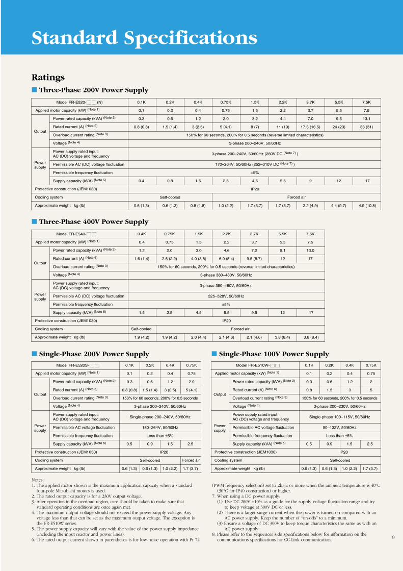
Standard Specifications
Notes:1. The applied motor shown is the maximum application capacity when a standard
four-pole Mitsubishi motors is used.2. The rated output capacity is for a 230V output voltage.3. After operation in the overload region, care should be taken to make sure that
standard operating conditions are once again met.4. The maximum output voltage should not exceed the power supply voltage. Any
voltage less than that can be set as the maximum output voltage. The exception isthe FR-E510W series.
5. The power supply capacity will vary with the value of the power supply impedance(including the input reactor and power lines).
6. The rated output current shown in parentheses is for low-noise operation with Pr. 72
(PWM frequency selection) set to 2kHz or more when the ambient temperature is 40°C(30°C for IP40 construction) or higher.
7. When using a DC power supply:(1) Use DC 280V ±10% as a guide for the supply voltage fluctuation range and try
to keep voltage at 300V DC or less.(2) There is a larger surge current when the power is turned on compared with an
AC power supply. Keep the number of “on-offs” to a minimum.(3) Ensure a voltage of DC 300V to keep torque characteristics the same as with an
AC power supply.8. Please refer to the sequencer side specifications below for information on the
communications specifications for CC-Link communication.
Forced air
Powersupply
Applied motor capacity (kW) (Note 1)
Power rated capacity (kVA) (Note 2)
Rated current (A) (Note 6)
Overload current rating (Note 3)
Voltage (Note 4)
Power supply rated input:AC (DC) voltage and frequency
Permissible AC (DC) voltage fluctuation
Permissible frequency fluctuation
Supply capacity (kVA) (Note 5)
Output150% for 60 seconds, 200% for 0.5 seconds (reverse limited characteristics)
3-phase 200–240V, 50/60Hz
3-phase 200–240V, 50/60Hz (280V DC (Note 7) )
170–264V, 50/60Hz (252–310V DC (Note 7) )
±5%
0.1K
0.1
0.3
0.8 (0.8)
0.2K
0.2
0.6
1.5 (1.4)
0.4K
0.4
1.2
3 (2.5)
0.75K
0.75
2.0
5 (4.1)
1.5K
1.5
3.2
8 (7)
2.2K
2.2
4.4
11 (10)
3.7K
3.7
7.0
17.5 (16.5)
5.5K
5.5
9.5
24 (23)
7.5K
7.5
13.1
33 (31)
0.4
0.6 (1.3)
0.8
Self-cooled
0.6 (1.3)
1.5
0.8 (1.8)
2.5
1.0 (2.2)
4.5
IP20
1.7 (3.7)
5.5
1.7 (3.7)
9
2.2 (4.9)
12
4.4 (9.7)
17
4.9 (10.8)
Protective construction (JEM1030)
Cooling system
Approximate weight kg (lb)
Model FR-E520- (N)
Forced air
Powersupply
Applied motor capacity (kW) (Note 1)
Power rated capacity (kVA) (Note 2)
Rated current (A) (Note 6)
Overload current rating (Note 3)
Voltage (Note 4)
Power supply rated input:AC (DC) voltage and frequency
Permissible AC voltage fluctuation
Permissible frequency fluctuation
Supply capacity (kVA) (Note 5)
Output150% for 60 seconds, 200% for 0.5 seconds
3-phase 200–240V, 50/60Hz
Single-phase 200–240V, 50/60Hz
180–264V, 50/60Hz
Less than ±5%
0.1K
0.1
0.3
0.8 (0.8)
0.2K
0.2
0.6
1.5 (1.4)
0.4K
0.4
1.2
3 (2.5)
0.75K
0.75
2.0
5 (4.1)
0.5
0.6 (1.3)
0.9
IP20
Self-cooled
0.6 (1.3)
1.5
1.0 (2.2)
2.5
1.7 (3.7)
Protective construction (JEM1030)
Cooling system
Approximate weight kg (lb)
Model FR-E520S-
Powersupply
Applied motor capacity (kW) (Note 1)
Power rated capacity (kVA) (Note 2)
Rated current (A) (Note 6)
Overload current rating (Note 3)
Voltage (Note 4)
Power supply rated input:AC (DC) voltage and frequency
Permissible AC voltage fluctuation
Permissible frequency fluctuation
Supply capacity (kVA) (Note 5)
Output150% for 60 seconds, 200% for 0.5 seconds
3-phase 200–230V, 50/60Hz
Single-phase 100–115V, 50/60Hz
90–132V, 50/60Hz
Less than ±5%
0.1K
0.1
0.3
0.8
0.2K
0.2
0.6
1.5
0.4K
0.4
1.2
3
0.75K
0.75
2
5
0.5
0.6 (1.3)
0.9
IP20
0.6 (1.3)
1.5
1.0 (2.2)
2.5
1.7 (3.7)
Protective construction (JEM1030)
Cooling system
Approximate weight kg (lb)
Model FR-E510W-
Self-cooled
Three-Phase 200V Power Supply
Forced airSelf-cooled
Powersupply
Applied motor capacity (kW) (Note 1)
Power rated capacity (kVA) (Note 2)
Rated current (A) (Note 6)
Overload current rating (Note 3)
Voltage (Note 4)
Power supply rated input:AC (DC) voltage and frequency
Permissible AC (DC) voltage fluctuation
Permissible frequency fluctuation
Supply capacity (kVA) (Note 5)
Output150% for 60 seconds, 200% for 0.5 seconds (reverse limited characteristics)
3-phase 380–480V, 50/60Hz
3-phase 380–480V, 50/60Hz
325–528V, 50/60Hz
±5%
0.4K
0.4
1.2
1.6 (1.4)
0.75K
0.75
2.0
2.6 (2.2)
1.5K
1.5
3.0
4.0 (3.8)
2.2K
2.2
4.6
6.0 (5.4)
3.7K
3.7
7.2
9.5 (8.7)
5.5K
5.5
9.1
12
7.5K
7.5
13.0
17
1.5
1.9 (4.2)
2.5
1.9 (4.2)
4.5
2.0 (4.4)
5.5
IP20
2.1 (4.6)
9.5
2.1 (4.6)
12
3.8 (8.4)
17
3.8 (8.4)
Protective construction (JEM1030)
Cooling system
Approximate weight kg (lb)
Model FR-E540- Three-Phase 400V Power Supply
Single-Phase 200V Power Supply Single-Phase 100V Power Supply
Ratings
Standard Specifications
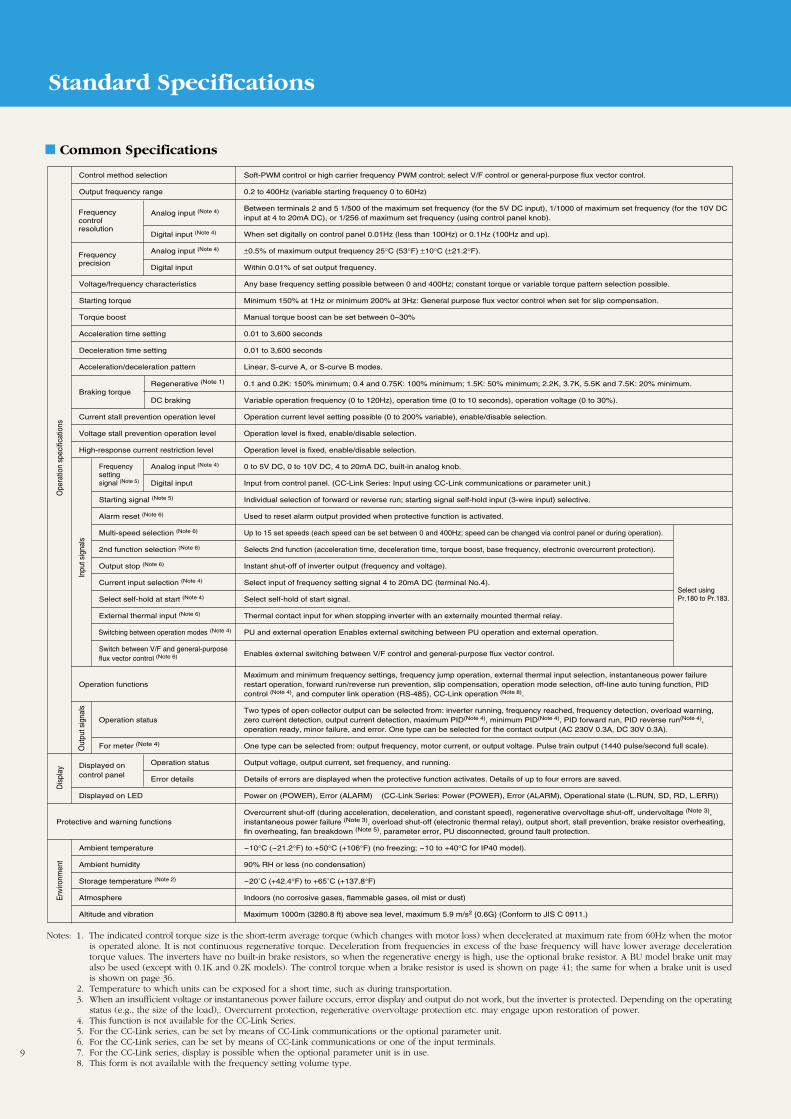
Common Specifications
Out
put s
igna
ls
Ope
ratio
n sp
ecifi
catio
ns
Control method selection Soft-PWM control or high carrier frequency PWM control; select V/F control or general-purpose flux vector control.
Output frequency range 0.2 to 400Hz (variable starting frequency 0 to 60Hz)
Analog input (Note 4) Between terminals 2 and 5 1/500 of the maximum set frequency (for the 5V DC input), 1/1000 of maximum set frequency (for the 10V DC input at 4 to 20mA DC), or 1/256 of maximum set frequency (using control panel knob).
Digital input (Note 4) When set digitally on control panel 0.01Hz (less than 100Hz) or 0.1Hz (100Hz and up).
Analog input (Note 4) ±0.5% of maximum output frequency 25°C (53°F) ±10°C (±21.2°F).
Digital input Within 0.01% of set output frequency.
Voltage/frequency characteristics Any base frequency setting possible between 0 and 400Hz; constant torque or variable torque pattern selection possible.
Starting torque Minimum 150% at 1Hz or minimum 200% at 3Hz: General purpose flux vector control when set for slip compensation.
Torque boost Manual torque boost can be set between 0–30%
Acceleration time setting 0.01 to 3,600 seconds
Deceleration time setting 0.01 to 3,600 seconds
Acceleration/deceleration pattern Linear, S-curve A, or S-curve B modes.
Regenerative (Note 1) 0.1 and 0.2K: 150% minimum; 0.4 and 0.75K: 100% minimum; 1.5K: 50% minimum; 2.2K, 3.7K, 5.5K and 7.5K: 20% minimum.Braking torque
DC braking Variable operation frequency (0 to 120Hz), operation time (0 to 10 seconds), operation voltage (0 to 30%).
Current stall prevention operation level Operation current level setting possible (0 to 200% variable), enable/disable selection.
Voltage stall prevention operation level Operation level is fixed, enable/disable selection.
High-response current restriction level Operation level is fixed, enable/disable selection.
Analog input (Note 4) 0 to 5V DC, 0 to 10V DC, 4 to 20mA DC, built-in analog knob.
Digital input Input from control panel. (CC-Link Series: Input using CC-Link communications or parameter unit.)
Starting signal (Note 5) Individual selection of forward or reverse run; starting signal self-hold input (3-wire input) selective.
Alarm reset (Note 6) Used to reset alarm output provided when protective function is activated.
Multi-speed selection (Note 6) Up to 15 set speeds (each speed can be set between 0 and 400Hz; speed can be changed via control panel or during operation).
2nd function selection (Note 6) Selects 2nd function (acceleration time, deceleration time, torque boost, base frequency, electronic overcurrent protection).
Output stop (Note 6) Instant shut-off of inverter output (frequency and voltage).
Current input selection (Note 4) Select input of frequency setting signal 4 to 20mA DC (terminal No.4).
Select self-hold at start (Note 4) Select self-hold of start signal.
External thermal input (Note 6) Thermal contact input for when stopping inverter with an externally mounted thermal relay.
Switching between operation modes (Note 4) PU and external operation Enables external switching between PU operation and external operation.
Switch between V/F and general-purpose flux vector control (Note 6) Enables external switching between V/F control and general-purpose flux vector control.
Maximum and minimum frequency settings, frequency jump operation, external thermal input selection, instantaneous power failureOperation functions restart operation, forward run/reverse run prevention, slip compensation, operation mode selection, off-line auto tuning function, PID
control (Note 4), and computer link operation (RS-485), CC-Link operation (Note 8).
Two types of open collector output can be selected from: inverter running, frequency reached, frequency detection, overload warning, Operation status zero current detection, output current detection, maximum PID(Note 4), minimum PID(Note 4), PID forward run, PID reverse run(Note 4),
operation ready, minor failure, and error. One type can be selected for the contact output (AC 230V 0.3A, DC 30V 0.3A).
For meter (Note 4) One type can be selected from: output frequency, motor current, or output voltage. Pulse train output (1440 pulse/second full scale).
Operation status Output voltage, output current, set frequency, and running.
Error details Details of errors are displayed when the protective function activates. Details of up to four errors are saved.
Displayed on LED Power on (POWER), Error (ALARM) (CC-Link Series: Power (POWER), Error (ALARM), Operational state (L.RUN, SD, RD, L.ERR))
Overcurrent shut-off (during acceleration, deceleration, and constant speed), regenerative overvoltage shut-off, undervoltage (Note 3),instantaneous power failure (Note 3), overload shut-off (electronic thermal relay), output short, stall prevention, brake resistor overheating,fin overheating, fan breakdown (Note 5), parameter error, PU disconnected, ground fault protection.
Ambient temperature -10°C (-21.2°F) to +50°C (+106°F) (no freezing; -10 to +40°C for IP40 model).
Ambient humidity 90% RH or less (no condensation)
Storage temperature (Note 2) -20˚C (+42.4°F) to +65˚C (+137.8°F)
Atmosphere Indoors (no corrosive gases, flammable gases, oil mist or dust)
Altitude and vibration Maximum 1000m (3280.8 ft) above sea level, maximum 5.9 m/s2 0.6G (Conform to JIS C 0911.)
Frequencycontrolresolution
Env
ironm
ent
Dis
play
Frequencyprecision
Inpu
t sig
nals
Frequency settingsignal (Note 5)
Select usingPr.180 to Pr.183.
Displayed oncontrol panel
Protective and warning functions
9
Notes: 1. The indicated control torque size is the short-term average torque (which changes with motor loss) when decelerated at maximum rate from 60Hz when the motoris operated alone. It is not continuous regenerative torque. Deceleration from frequencies in excess of the base frequency will have lower average decelerationtorque values. The inverters have no built-in brake resistors, so when the regenerative energy is high, use the optional brake resistor. A BU model brake unit mayalso be used (except with 0.1K and 0.2K models). The control torque when a brake resistor is used is shown on page 41; the same for when a brake unit is usedis shown on page 36.
2. Temperature to which units can be exposed for a short time, such as during transportation.3. When an insufficient voltage or instantaneous power failure occurs, error display and output do not work, but the inverter is protected. Depending on the operating
status (e.g., the size of the load),. Overcurrent protection, regenerative overvoltage protection etc. may engage upon restoration of power.4. This function is not available for the CC-Link Series.5. For the CC-Link series, can be set by means of CC-Link communications or the optional parameter unit.6. For the CC-Link series, can be set by means of CC-Link communications or one of the input terminals.7. For the CC-Link series, display is possible when the optional parameter unit is in use.8. This form is not available with the frequency setting volume type.
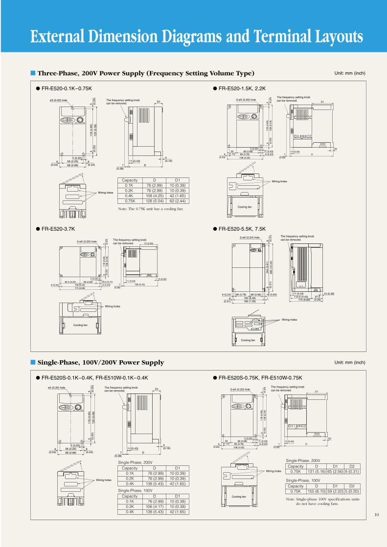
Three-Phase, 200V Power Supply (Frequency Setting Volume Type)
10
External Dimension Diagrams and Terminal Layouts
Single-Phase, 100V/200V Power Supply
Capacity D D10.1K 76 (2.99) 10 (0.39)0.2K 76 (2.99) 10 (0.39)0.4K 108 (4.25) 42 (1.65)0.75K 128 (5.04) 62 (2.44)
Unit: mm (inch)
Unit: mm (inch)
Note: The 0.75K unit has a cooling fan.
56 (2.20)
ø5 (0.20) hole
68 (2.68)
5 (0.20)
5 (0.2
0)5 (0
.20)
118
(4.6
5)
129
(5.0
8)
6(0.24)
6(0.24)
4(0.16)
D
D1
7(0.28)
11 (0.43)
The frequency setting knobcan be removed.
Wiring holes
72 (2.83)
138 (5.43)7(0.28)
11 (0.43)82.5 (3.25) 68 (2.68) 19.5 (0.77)158 (6.22)170 (6.69)
6 (0.24)6 (0.24)
5 (0.20)
118
(4.6
5)12
8 (5
.04)
5 (0.2
0)5 (0
.20)
Cooling fan
The frequency setting knobcan be removed.
Wiring holes
2-ø5 (0.20) hole
5 (0.20)
29(1.14)
68 (2.68)96 (3.78) 6 (0.24)6
(0.24) 108 (4.25)
11 (0.43)5 (0.20)
5 (0.2
0)5 (0
.20)
118
(4.6
5)12
8 (5
.04)
D1
7(0.28)
11 (0.43)D2
D
Cooling fan
The frequency setting knobcan be removed.
Wiring holes
2-ø5 (0.20) hole
FR-E520-0.1K–0.75K
FR-E520-3.7K
FR-E520-1.5K, 2.2K
Capacity D D10.1K 76 (2.99) 10 (0.39)0.2K 76 (2.99) 10 (0.39)0.4K 138 (5.43) 42 (1.65)
56 (2.20)
ø5 (0.20) hole
68 (2.68)
5 (0.20)
5 (0.2
0)5 (0
.20)
118
(4.6
5)
129
(5.0
8)
6(0.24)
6(0.24)
4(0.16)
D
D1
7(0.28)
11 (0.43)
The frequency setting knobcan be removed.
Wiring holes
29(1.14)
68 (2.68)96 (3.78) 6 (0.24)6
(0.24) 108 (4.25)
11 (0.43)5 (0.20)
5 (0.2
0)5 (0
.20)
118
(4.6
5)12
8 (5
.04)
D1
7(0.28)
11 (0.43)D2
D
Cooling fan
The frequency setting knobcan be removed.
Wiring holes
2-ø5 (0.20) hole
FR-E520S-0.1K–0.4K, FR-E510W-0.1K–0.4K FR-E520S-0.75K, FR-E510W-0.75K
FR-E520-5.5K, 7.5K
180 (7.09)164 (6.46) t8
(0.31)
8 (0.3
1)8 (0
.31)
244
(9.6
1)26
0 (1
0.24
)
6 (0.24) 96 (3.78) 68 (2.68)
2-ø6 (0.24) hole
16 (0.63) 10 (0.39)
170 (6.69)
11 (0.43)112.5 (4.43) 57.5
(2.26)
Wiring holes
Cooling fan
The frequency setting knobcan be removed.
Single-Phase, 200V
Capacity D D10.1K 76 (2.99) 10 (0.39)0.2K 106 (4.17) 10 (0.39)0.4K 138 (5.43) 42 (1.65)
Single-Phase, 100V
Capacity D D1 D20.75K 131 (5.16) 65 (2.56) 8 (0.31)
Single-Phase, 200V
Capacity D D1 D20.75K 155 (6.10) 59 (2.32) 5 (0.20)
Single-Phase, 100V
Note: Single-phase 100V specifications unitsdo not have cooling fans.
External Dimension Diagrams and Terminal Layouts
11
Three-Phase, 200V Power Supply (CC-Link)
Three-Phase, 400V Power Supply
NP
140 (5.51)
128 (5.04)D1
128 (5.04)
2-ø5
(0.2
0)
5(0.20)
7(0.28)
D
138
(5.4
3)
150
(5.9
1)
Cooling fan
The frequency setting knobcan be removed
73 (2.87)
150
(5.9
1)
The frequency setting knobcan be removed
220 (8.66)
208 (8.19)
2-ø5
(0.2
0)
138
(5.4
3)
238 (9.37)
5(0.20)
7(0.28)
148 (5.83)
Cooling fan
Unit: mm (inch)
Unit: mm (inch)
FR-E520-0.1KN, 0.2KN, 0.4KN, 0.75KN
FR-E520-3.7KN
FR-E520-1.5KN, 2.2KN
FR-E520-5.5KN, 7.5KN
6(0.24)
5 (0.20)
5 (0.2
0)11
8 (4
.65)
128
(5.0
4)
5 (0.2
0
6(0.24)
56 (2.20)66 (2.60)
55 (2.17)D
30.6(1.20)
D14(0.16)
ø5 (0.20) hole
Wiring holes
68 (2.68) 11 (0.43)29(1.14) 96 (3.78)6
(0.24)6(0.24)108 (4.25)
5
5 (0.2
0)5 (0
.20)
118
(4.6
5)
128
(5.0
4)
150.6 (5.93)
30.6(1.20)
55 (2.17) 65 (2.56)8(0.31)
2-ø5 (0.20) hole
Wiring holes
170 (6.70)
157.6 (6.20)30.6
(1.20)55 (2.17) 72 (2.83)
5(0.20)
158 (6.22)55 (2.17) 114.5 (4.51)
6(0.24)
6(0.24)
62.5 (2.46) 68 (2.68) 19.5(0.77)
5 (0.20)
5 (0.2
0)5 (0
.20)
118
(4.6
5)12
8 (5
.04)
2-ø5 (0.20) hole
Wiring holes164 (6.46)8 (0.31) 8 (0.31)180 (7.09)
68 (2.68) 16 (0.63)
244
(9.6
1)8 (0
.31)
8 (0
.31)
260
(10.
24)
96 (3.78)6 (0.24)
189.6 (7.46)170 (6.69)
112.5 (4.43) 57.5(2.26)19.6
(0.77)
10 (0.39)11 (0.43)
2-ø6 (0.24) hole
Wiring holes
Capacity D D10.1KN 95.6 (3.76) 10 (0.39)0.2KN 95.6 (3.76) 10 (0.39)0.4KN 127.6 (5.02) 42 (1.65)0.75KN 147.6 (5.81) 62 (2.44)
Note: The 0.75K unit has a cooling fan.
Capacity D D10.4/0.75K 116 (4.57) 44 (1.73)1.5–3.7K 136 (5.35) 64 (2.52)
Note: FR-E540-0.4K, 0.75K do not have cooling fans.
∗ With the CC-Link option, a signal terminalmount protrudes about 14mm (0.55 inch)from the surface.
FR-E540-0.4K, 0.75K, 1.5K–3.7K FR-E540-5.5K, 7.5K
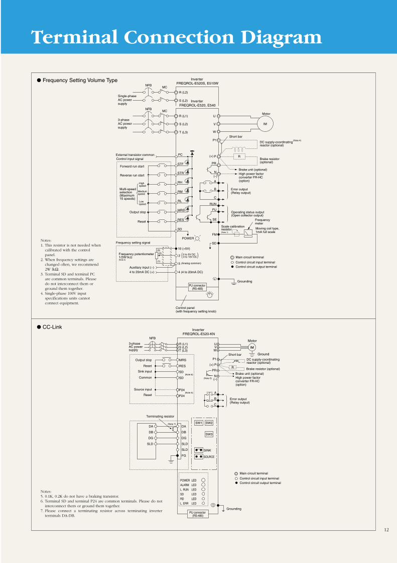
Terminal Connection Diagram
12
R (L1)
R (L2)
S (L2)
S (L2)
T (L3)
V
U
W
NFBMC
5
2
10 (+5V)
STF
STR
P1
P R
PR
N
PCExternal transistor common
Forward run start
Reverse run start
RH
RM
RL
MRS
RES
SD
0 to 5V DC0 to 10V DC
(3)(2)
(1)
4 (4 to 20mA DC)
IM
A
B
C
SD
FM
3-phase AC power supply
Multi-speed selection (Maximum15 speeds)
Highspeed
Mediumspeed
Lowspeed
Output stop
Reset
Control input signal
Frequency potentiometer 1/2W1kΩ (Note 2)
Auxiliary input (-)4 to 20mA DC (+)
Frequency setting signal
Grounding
Control panel(with frequency setting knob)
Moving coil type,1mA full scale
Frequency meter
Scale calibrationresistor (Note 1)
Operating status output(Open collector output)
Error output (Relay output)
Brake resistor (optional)
DC supply-coordinating reactor (optional)
Short bar
Brake unit (optional)
Motor
PU connector (RS-485)
Inverter FREQROL-E520, E540
Inverter FREQROL-E520S, E510W
Main circuit terminal
Control circuit input terminalControl circuit output terminal
(Analog common)
NFBMC
Single-phase AC power supply
RUN
FU
SE
High power factorconverter FR-HC(option)
POWER
( )
(+)
(-)
(Note 4)
Notes:1. This resistor is not needed when
calibrated with the controlpanel.
2. When frequency settings arechanged often, we recommend2W lkΩ.
3. Terminal SD and terminal PCare common terminals. Pleasedo not interconnect them orground them together.
4. Single-phase 100V inputspecifications units cannot connect equipment.
Notes:5. 0.1K, 0.2K do not have a braking transistor.6. Terminal SD and terminal P24 are common terminals. Please do not
interconnect them or ground them together.7. Please connect a terminating resistor across terminating inverter
terminals DA-DB.
CC-Link
Frequency Setting Volume Type
SW1 SW2
SW3
SINK
R (L1)S (L2)T (L3)
SOURCE
MRS
RES
SD
SD
P24
P24
DA
DB
DG
SLD
SLD
FG
DA
DB
DG
SLD
UVW
P1
(+) P
PR
N(–)
A
B
C
POWER LED
ALARM LED
L. RUN LED
SD LED
RD LED
L. ERR LED
NFB
Brake resistor (optional)
DC supply-coordinating reactor (optional)
Brake unit (optional)High power factorconverter FR-HC(option)
Error output (Relay output)
Main circuit terminal
Control circuit input terminalControl circuit output terminal
GroundingPU connector
(RS-485)
3-phase AC power supply
Output stop
Reset
Sink input
Common
Source input
Reset
Terminating resistor
Inverter FREQROL-E520-KN
Motor
Ground
(Note 5)
(Note 6)
(Note 5)
(Note 7)
Short bar
Notes: 1. The L level is when the open connector output transistor turns ON (continuity state). The H level is when it is OFF (non-continuity state).2. In the case of units with single-phase power input specifications, the only AC power input terminals are R and S.3. : Applicable. – : Not applicable.4. For the E540 models, terminals SD, 5 and SE are isolated. For other models, e.g. E510 terminal SE is isolated from terminals SD and 5.
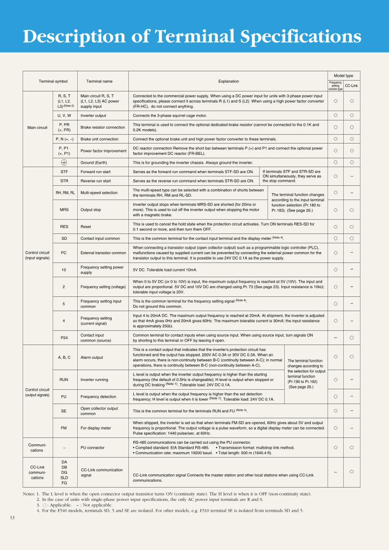
Description of Terminal Specifications
If terminals STF and STR-SD are ON simultaneously, they serve as the stop command.
The terminal function changesaccording to the input terminal function selection (Pr.180 toPr.183). (See page 26.)
The terminal functionchanges according to the selection for output terminal function (Pr.190 to Pr.192) (See page 26.)
Frequencysetting
volume type
Terminal symbol Terminal name
R, S, T Main circuit R, S, T Connected to the commercial power supply. When using a DC power input for units with 3-phase power input (L1, L2, (L1, L2, L3) AC power specifications, please connect it across terminals R (L1) and S (L2). When using a high power factor converter L3) supply input (FR-HC), do not connect anything.
U, V, W Inverter output Connects the 3-phase squirrel cage motor.
P, PRBrake resistor connection
This terminal is used to connect the optional dedicated brake resistor (cannot be connected to the 0.1K and (+, PR) 0.2K models).
P, N (+, -) Brake unit connection Connect the optional brake unit and high power factor converter to these terminals.
P, P1 Power factor improvement
DC reactor connection Remove the short bar between terminals P (+) and P1 and connect the optional power (+, P1) factor improvement DC reactor (FR-BEL).
Ground (Earth) This is for grounding the inverter chassis. Always ground the inverter.
STF Forward run start Serves as the forward run command when terminals STF-SD are ON.
STR Reverse run start Serves as the reverse run command when terminals STR-SD are ON.
RH, RM, RL Multi-speed selectionThe multi-speed type can be selected with a combination of shorts between the terminals RH, RM and RL-SD.
MRS Output stopInverter output stops when terminals MRS-SD are shorted (for 20ms or more). This is used to cut off the inverter output when stopping the motorwith a magnetic brake.
RES ResetThis is used to cancel the hold state when the protection circuit activates. Turn ON terminals RES-SD for 0.1 second or more, and then turn them OFF.
SD Contact input common This is the common terminal for the contact input terminal and the display meter (Note 4).
When connecting a transistor output (open collector output) such as a programmable logic controller (PLC), PC External transistor common malfunctions caused by supplied current can be prevented by connecting the external power common for the
transistor output to this terminal. It is possible to use 24V DC 0.1A as the power supply.
10 Frequency setting power
5V DC. Tolerable load current 10mA.supply
When 0 to 5V DC (or 0 to 10V) is input, the maximum output frequency is reached at 5V (10V). The input and 2 Frequency setting (voltage) output are proportional. 5V DC and 10V DC are changed using Pr.73 (See page 23). Input resistance is 10kΩ;
tolerable input voltage is 20V.
5 Frequency setting input This is the common terminal for the frequency setting signal (Note 4).
common Do not ground this common.
4
Frequency settingInput 4 to 20mA DC. The maximum output frequency is reached at 20mA. At shipment, the inverter is adjusted
(current signal)so that 4mA gives 0Hz and 20mA gives 60Hz. The maximum tolerable current is 30mA; the input resistance is approximately 250Ω.
P24Contact input Common terminal for contact inputs when using source input. When using source input, turn signals ON common (source) by shorting to this terminal or OFF by leaving it open.
This is a contact output that indicates that the inverter's protection circuit has functioned and the output has stopped. 200V AC 0.3A or 30V DC 0.3A. When an
A, B, C Alarm output alarm occurs, there is non-continuity between B-C (continuity between A-C); in normal
operations, there is continuity between B-C (non-continuity between A-C).
L level is output when the inverter output frequency is higher than the starting RUN Inverter running frequency (the default of 0.5Hz is changeable); H level is output when stopped or
during DC braking (Note 1). Tolerable load: 24V DC 0.1A.
FU Frequency detection L level is output when the output frequency is higher than the set detection
frequency; H level is output when it is lower (Note 1). Tolerable load: 24V DC 0.1A.
SE Open collector output
This is the common terminal for the terminals RUN and FU (Note 4).common
When shipped, the inverter is set so that when terminals FM-SD are opened, 60Hz gives about 5V and output FM For display meter frequency is proportional. The output voltage is a pulse waveform, so a digital display meter can be connected.
Pulse specification: 1440 pulse/sec. at 60Hz.
RS-485 communications can be carried out using the PU connector. – PU connector • Complied standard: EIA Standard RS-485. • Transmission format: multidrop link method.
• Communication rate: maximum 19200 baud. • Total length: 500 m (1640.4 ft).
DADBDGSLDFG
Explanation
Control circuit(input signals)
Control circuit(output signals)
Communi-cations
CC-Linkcommuni-
cations
CC-Link communication signal
Main circuit
CC-Link
Model type
–
–
–
–
–
–
–
–
–
–
–
–
–
(Note 2)
CC-Link communication signal Connects the master station and other local stations when using CC-Link communications.
13
Operation
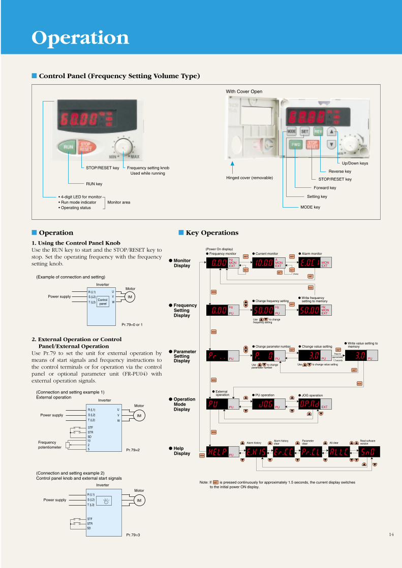
14
Control Panel (Frequency Setting Volume Type)
Operation
1. Using the Control Panel KnobUse the RUN key to start and the STOP/RESET key tostop. Set the operating frequency with the frequencysetting knob.
Key Operations
2. External Operation or Control Panel/External Operation
Use Pr.79 to set the unit for external operation bymeans of start signals and frequency instructions tothe control terminals or for operation via the controlpanel or optional parameter unit (FR-PU04) withexternal operation signals.
Power supplyR (L1)
S (L2)
T (L3)
InverterMotor
U
V
W
IMControl panel
Pr.79=0 or 1
(Example of connection and setting)
With Cover Open
IM
Motor
Pr.79=2
Power supply
Frequency potentiometer
Inverter
R (L1)
S (L2)
T (L3)
STF
STRSD1025
U
V
W
(Connection and setting example 1)External operation
IM
Motor
Pr.79=3
Power supply
Inverter
STF
STRSD
(Connection and setting example 2)Control panel knob and external start signals
R (L1)
S (L2)
T (L3)
SETSETSET
MODE
MODE
MODE
MODE
MODE
MODE
SET
SET
SET
SET SET
SET
MODE
SET
(Note)
Use to change value setting
SETNote: If is pressed continuously for approximately 1.5 seconds, the current display switches to the initial power ON display.
Frequency monitor
External operation
Current monitor
Change frequency setting Write frequency
setting to memory
Alarm monitor
Change parameter number Change value setting
PU operation
Alarm historyAlarm history clear
Parameter clear All clear
Read software version
JOG operation
Write value setting to memory
Monitor Display
Frequency Setting
Display
Help Display
Operation Mode
Display
Parameter Setting
Display
(Power On display)
Use to change frequency setting
Use to change parameter number
Press for approximately 1.5 seconds
HzMONEXT
AMONEXT
MONEXT
Hz
PU
Hz
PU
HzMONEXT
PU PU PU
PU
PU
PU EXT
PU
STOP/RESET key Frequency setting knob Used while running
RUN key
• 4-digit LED for monitor• Run mode indicator Monitor area• Operating status
Hinged cover (removable)
Up/Down keys
Reverse key
STOP/RESET key
Forward key
Setting key
MODE key
List of Parameters
15
Function Pr. No. Name Setting range Minimum setting Default setting
Basic functions
Standard operation functions
Output terminal functions
Display functions
Restart
Supplementary functions
Operation selection functions
2nd functions
0 Torque boost (Note 1) 0 to 30% 0.1% 6% / 4% (Note 9)
1 Maximum frequency 0 to 120Hz 0.01Hz 120Hz
2 Minimum frequency 0 to 120Hz 0.01Hz 0Hz
3 Base frequency (Note 1) 0 to 400Hz 0.01Hz 60Hz
4 Multi-speed setting (high speed) 0 to 400Hz 0.01Hz 60Hz
5 Multi-speed setting (middle speed) 0 to 400Hz 0.01Hz 30Hz
6 Multi-speed setting (low speed) 0 to 400Hz 0.01Hz 10Hz
7 Acceleration time 0 to 3600 s / 0 to 360 s 0.1 s / 0.01 s 5 s
8 Deceleration time 0 to 3600 s / 0 to 360 s 0.1 s / 0.01 s 5 s
9 Electronic thermal O/L relay 0 to 500A 0.1A Rated output current
10 DC injection brake operation frequency 0 to 120Hz 0.01Hz 3Hz
11 DC injection brake operation time 0 to 10 s 0.1 s 0.5 s
12 DC injection brake voltage 0 to 30% 0.1% 6 %
13 Starting frequency 0 to 60Hz 0.01Hz 0.5Hz
14 Load pattern selection (Note 1) 0 to 3 1 0
15 JOG frequency 0 to 400Hz 0.01Hz 5Hz
16 JOG acceleration/deceleration time 0 to 3600 s / 0 to 360 s 0.1 s / 0.01 s 0.5 s
18 High speed maximum frequency 120 to 400Hz 0.01Hz 120Hz
19 Base frequency voltage (Note 1) 0 to 1000V, 8888, 9999 0.1V 9999
20 Acceleration/deceleration reference frequency 1 to 400Hz 0.01Hz 60Hz
21 Acceleration/deceleration time increments 0, 1 1 0
22 Stall prevention operation level 0 to 200% 0.1% 150%
23 Stall prevention operation at double speed (Note 3) 0 to 200%, 9999 0.1% 9999
24 Multi-speed setting (speed 4) 0 to 400Hz, 9999 0.01Hz 9999
25 Multi-speed setting (speed 5) 0 to 400Hz, 9999 0.01Hz 9999
26 Multi-speed setting (speed 6) 0 to 400Hz, 9999 0.01Hz 9999
27 Multi-speed setting (speed 7) 0 to 400Hz, 9999 0.01Hz 9999
29 Acceleration/deceleration pattern selection 0, 1, 2 1 0
30 Regenerative function selection 0, 1 1 0
31 Frequency jump 1A 0 to 400Hz, 9999 0.01Hz 9999
32 Frequency jump 1B 0 to 400Hz, 9999 0.01Hz 9999
33 Frequency jump 2A 0 to 400Hz, 9999 0.01Hz 9999
34 Frequency jump 2B 0 to 400Hz, 9999 0.01Hz 9999
35 Frequency jump 3A 0 to 400Hz, 9999 0.01Hz 9999
36 Frequency jump 3B 0 to 400Hz, 9999 0.01Hz 9999
37 Speed display 0, 0.01 to 9998 0.001 r/min 0
38 Frequency at 5V (10V) input 1 to 400Hz 0.01Hz 60Hz (Note 4)
39 Frequency at 20mA input 1 to 400Hz 0.01Hz 60Hz (Note 4)
41 Up-to-frequency sensitivity 0 to 100% 0.1% 10%
42 Output frequency detection 0 to 400Hz 0.01Hz 6Hz
43 Output frequency detection for reverse rotation 0 to 400Hz, 9999 0.01Hz 9999
44 2nd acceleration/deceleration time 0 to 3600 s / 0 to 360 s 0.1 s / 0.01 s 5 s / 10 s (Note 7)
45 2nd deceleration time 0 to 3600 s / 0 to 360 s, 9999 0.1 s / 0.01 s 9999
46 2nd torque boost 0 to 30%, 9999 0.1% 9999
47 2nd V/F (base frequency) 0 to 400Hz, 9999 0.01Hz 9999
48 2nd electronic thermal O/L relay 0 to 500A, 9999 0.01A 9999
52 Control Panel /PU main display data 0, 23, 100 1 0
54 FM terminal function selection 0, 1, 2 1 0
55 Frequency monitoring reference 0 to 400Hz 0.01Hz 60
56 Current monitoring reference 0 to 500A 0.01A Rated output current
57 Restart coasting time 0 to 5 s, 9999 0.1 s 9999
58 Restart cushion time 0 to 60 s 0.1 s 1.0 s
59 Remote setting function selection 0, 1, 2 1 0
60 Shortest acceleration/deceleration time 0, 1, 2, 11, 12 1 0
65 Retry selection 0, 1, 2, 3 1 0
66 Stall prevention operation level reduction starting frequency (Note 3) 0 to 400Hz 0.01Hz 60Hz
67 Number of retries at alarm occurrence 0 to 10, 101 to 110 1 0
68 Retry waiting time 0.1 to 360 s 0.1 s 1 s
69 Retry count display erasure 0 1 0
70 Special regenerative brake duty 0 to 30% 0.1% 0%
71 Applied motor (Note 3) 0, 1, 5, 6, 15, 16, 23, 101 to 123 1 0
72 PWM frequency selection 0 to 15 1 1
73 0 to 5V, 0 to 10V selection 0, 1 1 0
74 Filter time constant 0 to 8 1 1
75 Reset selection /disconnected PU detection/PU stop selection 0 to 3, 14 to 17 1 14
77 Parameter write disable selection 0, 1, 2 1 0
78 Reverse rotation prevention selection 0, 1, 2 1 0
79 Operation mode selection (Note 3) 0 to 4, 6 to 8 1 0
80 Motor capacity 0.1 to 3.7kW, 9999 0.01kW 9999
82 Motor excitation current 0 to 500A, 9999 0.01A 9999
83 Rated motor voltage 0 to 1000V 0.1V 200V / 400V
84 Rated motor frequency 0 to 400Hz 0.01Hz 60Hz
90 Motor constant (R1) 0 to 50Ω, 9999 0.001Ω 9999
96 Auto-tuning setting/status (Note 3) 0, 1 1 0
Frequencysetting
volume typeCC-Link
Series name
––
––
–––
–
––
General-purpose flux vectorcontrol
16
Communications functions
PID control
Indication
Supplementary function
Current detection
User functions
Terminal function selection
Auxiliary function
Supplementary function
Manufacturersparameter
Initial monitor
Multi-speed operations
Standard operation function
Auxiliary function
Function selection
Calibration functions
Stop selection functions
Auxiliary functions
117 Station number 0 to 31 1 0
118 Communication speed 48, 96, 192 1 48
119 Stop bit length/data length 0, 1 (data length 8), 10, 11 (data length 7) 1 1
120 Parity check presence/absence 0,1, 2 1 2
121 Number of communication retries 0 to 10, 9999 1 1
122 Communication check time interval 0 to 999.8 s, 9999 0.1 s 0
123 Waiting time setting 0 to 15, 9999 2 9999
124 CR/LF presence/absence selection 0, 1, 2 1 1
128 PID action selection 0, 1, 9999 1 0
129 PID proportional band 0.1 to 1000%, 9999 0.1 s 100%
130 PID integral time 0.1 to 3600 s, 9999 0.1 s 1 s
131 Upper limit 0 to 100%, 9999 1% 9999
132 Lower limit 0 to 100%, 9999 1% 9999
133 PID action set point for PU operation 0 to 100% 1% 0%
134 PID differential time 0.01 to 10.00 s, 9999 0.01 s 9999
145 Display language (When using FR-PU04) 0 to 7 1 23
146 Select frequency setting instruction 0, 1, 9999 1 0
150 Output current detection level 0 to 200%, 9999 0.1% 150%
151 Output current detection period 0 to 10 s 0.1 s 0
152 Zero current detection level 0 to 200.0% 0.1% 5.0%
153 Zero current detection period 0.05 to 1 s 0.01 s 0. 5 s
156 Stall prevention operation selection 0 to 31, 100 1 0
160 User group read selection 0, 1, 10, 11 1 0
168Parameter set by manufacturer. Do not set.
– – –
169 – – –
171 Actual operation hour meter clear 0 – 0
173 User group 1 registration 0 to 999 1 0
174 User group 1 deletion 0 to 999, 9999 1 0
175 User group 2 registration 0 to 999 1 0
176 User group 2 deletion 0 to 999, 9999 1 0
180 RL terminal function selection (RY4) 0 to 8, 16, 18 1 0
181 RM terminal function selection (RY3) 0 to 8, 16, 18 1 1
182 RH terminal function selection (RY2) 0 to 8, 16, 18 1 2
183 MRS terminal (RY1) function selection 0 to 8, 16, 18 1 6
190 RUN terminal function selection (RX2) 0 to 99 1 0
191 FU terminal function selection (RX6) 0 to 99 1 4
192 A, B, C terminal (RY7) function selection 0 to 99 1 99
232 Multi-speed setting (speed 8) 0 to 400Hz, 9999 0.01Hz 9999
233 Multi-speed setting (speed 9) 0 to 400Hz, 9999 0.01Hz 9999
234 Multi-speed setting (speed 10) 0 to 400Hz, 9999 0.01Hz 9999
235 Multi-speed setting (speed 11) 0 to 400Hz, 9999 0.01Hz 9999
236 Multi-speed setting (speed 12) 0 to 400Hz, 9999 0.01Hz 9999
237 Multi-speed setting (speed 13) 0 to 400Hz, 9999 0.01Hz 9999
238 Multi-speed setting (speed 14) 0 to 400Hz, 9999 0.01Hz 9999
239 Multi-speed setting (speed 15) 0 to 400Hz, 9999 0.01Hz 9999
240 Soft-PWM setting 0, 1 1 1
244 Cooling fan operation selection 0, 1 1 0
245 Rated motor slip 0 to 50%, 9999 0.01% 9999
246 Slip compensation response time 0.01 to 10 s 0.01 s 0.05 s
247 Constant-output region slip compensation selection 0, 9999 – 9999
249 Ground fault detection at start-up (Y/N) (Note 8) 0, 1 1 0
250 Stop selection 0 to 100 s, 1000 to 1100 s, 8888, 9999 1 9999
900 FM terminal calibration – – –
902 Frequency setting voltage bias 0 to 10V 0 to 60Hz 0.01Hz 0V 0Hz
903 Frequency setting voltage gain 0 to 10V 1 to 400Hz 0.01Hz 5V 60Hz
904 Frequency setting current bias 0 to 20mA 0 to 60Hz 0.01Hz 4mA 0Hz
905 Frequency setting current gain 0 to 20mA 1 to 400Hz 0.01Hz 20mA 60Hz
922 Built-in knob bias 0 to 5V 0 to 60Hz 0.01Hz 0V 0Hz
923 Built-in knob gain 0 to 5V 0 to 400Hz 0.01Hz 5V 60Hz
990 Buzzer sound control (When using FR-PU04) 0, 1 1 1
991 LCD contrast (When using FR-PU04) 0 to 63 1 53
Function Pr. No. Name Setting range Minimum setting Default setting Frequencysetting
volume typeCC-Link
Series name
–––––––
–
–––––––
List of Parameters
Notes: 1. This indicates a parameter whose setting is ignored when general-purpose flux vector control mode is selected.2. The set values for the parameters in the shaded areas can be altered during operations even if Pr.77 ( Parameter write disable) is set to 0 (default setting). 3. Even if Pr.77 (Parameter write disable) is set to 2, the set value cannot be changed during operations.4. Since they are calibrated before shipment, settings will vary slightly from inverter to inverter. Some are set to a frequency is slightly higher than 60Hz.5. Some of the names of CC-Link Series functions differ from those of frequency setting volume type functions.6. : Applicable. – : Not applicable.7. The setting depends on the inverter capacity: (0.1K to 3.7K) / (5.5K to 7.5K)8. The ground fault detection setting parameter is not applicable to the FR-E540 series.
The FR-E540 series is automatically set to detect ground faults.9. The setting for the FR-E540-5.5K / 7.5K is 4%.
Description of Parameters
17
Pr.0–Pr.6Note: “Parameter” is sometimes abbreviated “Pr.”
Notes: 1. When general-purpose flux vector control mode is selected using Pr.80,this setting is ignored.
2. When using a motor that is dedicated for inverters (a constant torquemotor), change the settings as follows.0.1–0.75K: 6%; 1.5–3.7K: 2%If Pr.71 is changed to the settings for using constant torque motors, butthe default settings are not changed, the Pr.0 setting will switch to theabove values.
3. Default settingFR-E540.....4% Others.....6%
Setting Torque Boost The motor torque can be adjusted at low frequencies to match
the load.
Pr.0
100%
Pr. 0
Out
put v
olta
ge
Base frequency
Setting range
Output frequency (Hz)
Notes: 1. When Pr.24–Pr.27 and Pr.232–Pr.239 are set to 9999 (default setting),4–7 and 8–15 cannot be selected (or run).
2. Multi-speed settings have priority over analog input commands(between terminals 2 and 5 or 4 and 5).
3. Multi-speed settings can be done during PU operation or external operation.4. For three-speed settings (when Pr.24–Pr.27 and Pr.232–Pr.239 are not set),
selection of two or more speeds simultaneously will set the speed to thespeed set at the low speed signal terminal.
5. Terminals used for REX signal input are assigned by Pr.180 –Pr.183(input terminal function selection).
Setting Multi-Speeds
Three-speed setting (high speed)
Three-speed setting (middle speed)
Three-speed setting (low speed)
Multi-speed setting (speed 4)
Multi-speed setting (speed 5)
Multi-speed setting (speed 6)
Multi-speed setting (speed 7)
Multi-speed setting (speed 8)
Multi-speed setting (speed 9)
Multi-speed setting (speed 10)
Multi-speed setting (speed 11)
Multi-speed setting (speed 12)
Multi-speed setting (speed 13)
Multi-speed setting (speed 14)
Multi-speed setting (speed 15)
Speeds can be selected by simply switching the external contactsignals (RH, RM, RL, and REX signals).
All speeds (frequencies) can be set in the range 0-400Hz whilethe inverter is running. Change the settings by using thekeys while a multi-speed parameter is displayed. (Press the writekey to record the frequency setting in memory once you havereleased the keys.)
Up to 17 speeds can be set by combining the maximum frequency(Pr.1) and minimum frequency (Pr.2).
Pr.239
Pr.238
Pr.237
Pr.236
Pr.235
Pr.234
Pr.233
Pr.232
Pr.27
Pr.26
Pr.25
Pr.24
Pr.6
Pr.5
Pr.4
Pr.232–239Pr.24 –27Pr.4–6
100%
Out
put f
requ
ency
Maximumfrequency
Frequency settingsignal
Pr. 2
Pr. 1
5V(10V)
(20mA)
Minimumfrequency
100%
Out
put v
olta
ge
Setting range for base frequency
Base frequency
Pr. 19
Pr. 3 400Hz
Base frequencyvoltage (Note 1)
Note: Set Pr.18 if you need an maximum frequency of 120Hz or higher.
Setting Maximum andMinimum Frequencies
Maximum frequency Minimum frequency
The output frequency can be clamped by maximum and minimumfrequencies.
Pr.2Pr.1
Pr.2Pr.1
Note: When Pr.19 is set to 8888, the maximum output voltage is 95% of the powersupply voltage. When Pr.19 is set to 9999 (the default setting), the maximumoutput voltage is the same as the power supply voltage.
Setting the Base Frequency
Base frequency
Base frequency voltage
Any base frequency (the reference frequency at the motor's ratedtorque) can be set in the range of 0–400Hz to match the motorrating.
Motors rated at below the inverter's power supply voltage are bestused by setting Pr.19 (base frequency voltage). This is convenientwhen using, for example, a 200V rated motor with a 230V powersupply.
Pr.19
Pr.3
Pr.19Pr.3ON
ON
ON
ON
ON ON
ON
ON
ON
ON
ONRH
Speed 1(High)
Speed 2(Middle)
Speed 3(Low)
Speed4
Speed5 Speed
6
Speed8
Speed9
Speed10 Speed
11 Speed12 Speed
13 Speed14 Speed
15
Out
put f
requ
ency
RM
RL
REX
ON ON ON ON ON ON ON ON
ON ON ON ON
ON ON ON ON
ON ON ON ON
RH
RM
RL
REX
Description of Parameters
18
Pr.7–Pr.14
Notes: 1. For S-curve acceleration/deceleration pattern A (see Pr.29), the time isthat required to reach the base frequency (Pr.3).
2. The frequency output to the frequency setting signal (analog) is set byPr.38 or Pr.39.
Setting Acceleration/Deceleration Time
Acceleration time frequency
Deceleration time
Acceleration/deceleration reference
Acceleration/deceleration time increments
Pr.7 (acceleration time) is the time required from reach thereference frequency of Pr.20 from 0Hz; Pr.8 (deceleration time) isthe time required to reach 0Hz from the setting of Pr.20.
Pr.21 (acceleration/deceleration time increments) allows you toset the setting range and the minimum setting increment. Asetting of 0 provides a range 0–3600sec. (minimum increment of0.1sec.); a setting of 1 provides a range of 0–360sec. (minimumincrement 0.01sec.).
Pr.21
Pr.20
Pr.8
Pr.7
Pr.8Pr.7
Electronic Thermal O/L Relay The setting for motor overheating protection can be set as the
current value (A). Normally, the rated motor current for 50Hz isset. This provides the optimum protection characteristics for lowspeed operations, including when motor cooling power dropsduring low-speed operation.
When 0A is set, the motor protection function does not engage.(The inverter’s output transistor protection function does.)
When using a Mitsubishi fixed torque motor, set Pr.71 (appliedmotor) to 1, 13, 15, or 16, select the 100% continuous torquecharacteristics at low speed, and set the motor’s rated current inPr.9 (electronic thermal O/L relay).
The factory default setting is the inverter’s rated output current,except for 0.1–0.75K inverters, for which it is 85% of theinverter’s rated current.
When several motors are operated simultaneously, install anexternal thermal relay on each motor.
Pr.9
Pr. 20
Pr. 7 Pr. 8
Ope
ratin
g fr
eque
ncy
Deceleration TimeAcceleration
DC Injection BrakeAdjustment
DC injection brake operation frequency
DC injection brake operation time
DC injection brake voltage
The stopping precision for positioning or similar operations canbe adjusted to the load by setting the time for which the DCbrake torque (voltage) is activated during stopping and thefrequency at which the operation is started.
Pr.12
Pr.11
Pr.10
Pr.12Pr.11Pr.10
Setting the Starting Frequency The frequency at startup can be set in the range 0–60Hz.
Pr.13
Pr. 10
Pr. 11
Pr. 12
Out
put f
requ
ency
DC brakevoltage Operating
voltage
Operating time
Time
Time
Operating frequency
0
60
ON
Pr. 13
Output frequency (Hz)
Set
ran
ge
Frequency setting signal (V) Time
Forward
Note: When general-purpose flux vector control mode is selected with Pr.80, thisparameter setting is ignored.
Load Pattern Selection This allows you to select the optimum output characteristics (V/F
characteristics) for your application and load characteristics.
Pr.14
100%
100%
100%
100%
Pr.0 Pr.0
Out
put v
olta
geO
utpu
t vol
tage
Out
put v
olta
geO
utpu
t vol
tage
Base frequency
Output frequency (Hz)
Base frequency
Output frequency (Hz)
Base frequency
Output frequency (Hz)
Base frequency
Output frequency (Hz)
Forward
Reverse
Reverse
Forward
Fixed torque load(conveyors, dolleys, etc.)
Setting 0 (default)
For elevated loadsBoost during forward: Parameter 0 settingBoot during reverse: 0%
Setting 2
For elevated loadsBoot during forward: 0%Boost during reverse: Parameter 0 setting
Setting 3
Low-speed torque load(fans and pumps)
Setting 1
Pr.14 setting Output characteristics
0 Fixed torque load
1 Low-speed torque load
2 For fixed 0% boost during reverse
3 torque elevation 0% boost during forward
Description of Parameters
19
JOG Operation Settings
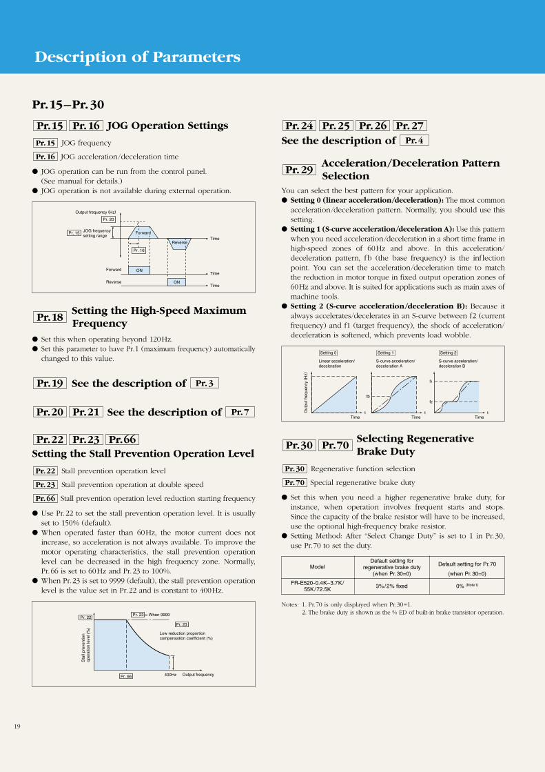
JOG frequency
JOG acceleration/deceleration time
JOG operation can be run from the control panel.(See manual for details.)
JOG operation is not available during external operation.
Pr.16
Pr.15
Pr.16Pr.15
ON
ON
Pr. 16
Pr. 20
Pr. 15
Output frequency (Hz)
JOG frequencysetting range
Forward
Forward
Reverse
Reverse
Time
Time
Time
Setting the High-Speed MaximumFrequency
Set this when operating beyond 120Hz. Set this parameter to have Pr.1 (maximum frequency) automatically
changed to this value.
Pr.18
Setting the Stall Prevention Operation Level
Stall prevention operation level
Stall prevention operation at double speed
Stall prevention operation level reduction starting frequency
Use Pr.22 to set the stall prevention operation level. It is usuallyset to 150% (default).
When operated faster than 60Hz, the motor current does notincrease, so acceleration is not always available. To improve themotor operating characteristics, the stall prevention operationlevel can be decreased in the high frequency zone. Normally,Pr.66 is set to 60Hz and Pr.23 to 100%.
When Pr.23 is set to 9999 (default), the stall prevention operationlevel is the value set in Pr.22 and is constant to 400Hz.
Pr.66
Pr.23
Pr.22
Pr.66Pr.23Pr.22
See the description of Pr.3Pr.19
See the description of Pr.7Pr.21Pr.20
Pr. 23 = When 9999Pr. 22
Pr. 23
Pr. 66 400Hz
Sta
ll pr
even
tion
oper
atio
n le
vel (
%)
Low reduction proportioncompensation coefficient (%)
Output frequency
Pr.15–Pr.30
See the description of Pr.4
Pr.27Pr.26Pr.25Pr.24
Acceleration/Deceleration PatternSelection
You can select the best pattern for your application. Setting 0 (linear acceleration/deceleration): The most common
acceleration/deceleration pattern. Normally, you should use thissetting.
Setting 1 (S-curve acceleration/deceleration A): Use this patternwhen you need acceleration/deceleration in a short time frame inhigh-speed zones of 60Hz and above. In this acceleration/deceleration pattern, fb (the base frequency) is the inf lectionpoint. You can set the acceleration/deceleration time to matchthe reduction in motor torque in fixed output operation zones of60Hz and above. It is suited for applications such as main axes ofmachine tools.
Setting 2 (S-curve acceleration/deceleration B): Because italways accelerates/decelerates in an S-curve between f2 (currentfrequency) and f1 (target frequency), the shock of acceleration/deceleration is softened, which prevents load wobble.
Pr.29
Selecting RegenerativeBrake Duty
Regenerative function selection
Special regenerative brake duty
Set this when you need a higher regenerative brake duty, forinstance, when operation involves frequent starts and stops.Since the capacity of the brake resistor will have to be increased,use the optional high-frequency brake resistor.
Setting Method: After “Select Change Duty” is set to 1 in Pr.30,use Pr.70 to set the duty.
Pr.70
Pr.30
Pr.70Pr.30
t t
tb
t
f2
f1
Setting 0
Linear acceleration/deceleration
Setting 1
S-curve acceleration/deceleration A
Setting 2
S-curve acceleration/deceleration B
Time Time Time
Out
put f
requ
ency
(H
z)
Model
FR-E520-0.4K–3.7K/3%/2% fixed 0% (Note1)
55K/72.5K
Default setting forregenerative brake duty
(when Pr.30=0)
Default setting for Pr.70
(when Pr.30=0)
Notes: 1. Pr.70 is only displayed when Pr.30=1.2. The brake duty is shown as the % ED of built-in brake transistor operation.
Description of Parameters
20
Pr.31–Pr.43
Notes: 1. No jumps are made when set to 9999 (the default).2. During acceleration or deceleration, the operating frequency in the set
range is passed over.
Frequency Jumps To bypass the resonant frequency of a piece of machinery, jump
over that frequency. You can set three jump points. The jumpfrequency can be the frequency either above or below the jumppoint.
The setting for 1A, 2A, or 3A becomes the jump point; operationis at this frequency.
Pr.31–36
1A1B
2A2B
3A3B
Pr. 31
Pr. 32
Pr. 33
Pr. 34
Pr. 35
Pr. 38
Out
put f
requ
ency
(H
z)
Jump (bypass operation) range
Frequency setting signal
*The operating frequency commandin the jump range is the operatingfrequency given in the bulleted item.
Notes: 1. The set unit is only used with this parameter for the PU monitor displayand setting operating speed. Other parameters for speeds (such as Pr.1)should be set as frequencies.
2. The speed display is converted from output frequency; it does not matchthe actual RPM.
3. Due to the setting resolution, frequencies set directly through the controlpanel may differ from operating speed.
Note: There is no need to input a 5V DC (or 10V DC) voltage between terminals2 and 5.
Setting the Speed Display Increment The actual operating speed of machinery such as conveyors can
be displayed. You can set the control panel monitor to showoperating speed in the same units as the speed specifications ofthe machinery you are using.
Set the machine speed when operated at 60Hz.
Pr.37
Frequency at 5V (10V) Input You can set the frequency when the frequency setting signal
input externally is 5V DC (or 10V DC).
Pr.38
• The output frequency is displayed (default setting).
Pr.37 setting Display
0
• Set the machine speed when operated at 60Hz.For example, if set for 950 (m/min.), 950 (without units) isdisplayed when 60Hz is output.
• The units of the operating speed are also converted in the display.
0.01–9998
fm 2
5V (10V)
fm 1 Pr. 38
Out
put f
requ
ency
(H
z) Output frequencyrange
Frequency setting signal
Note: There is no need to input a 20mA current between terminals 4 and 5.
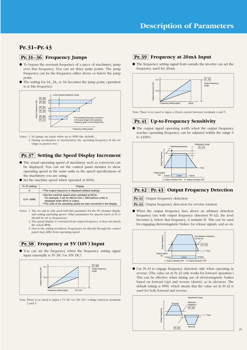
Frequency at 20mA Input The frequency setting signal from outside the inverter can set the
frequency used for 20mA.
Pr.39
fm 2
20mA
fm 1 Pr. 39
Out
put f
requ
ency
(H
z) Output frequencyrange
Frequency setting signal
Up-to-Frequency Sensitivity The output signal operating width when the output frequency
reaches operating frequency can be adjusted within the range 0to ±100%.
Pr.41
Pr. 41
Out
put f
requ
ency
Operating frequencyAdjustment range
Time
Output signalSU L levelH level H level
L: Output transistor ON H: Output transistor OFF
Output Frequency Detection
Output frequency detection
Output frequency detection for reverse rotation
When the output frequency rises above an arbitrary detectionfrequency (set with output frequency detection Pr.42), the levelbecomes L; below that frequency, it remains H. This can be usedfor engaging electromagnetic brakes, for release signals, and so on.
Pr.43
Pr.42
Pr.43Pr.42
Pr. 42
Out
put f
requ
ency Any detection frequency
can be set
TimeOutput signal
FUL levelH level H level
L: Output transistor ON H: Output transistor OFF
Pr. 42
Pr. 43
Out
put f
requ
ency
ForwardDetectionfrequency
Adjustment range
Reverse
Time
Use Pr.43 to engage frequency detection only when operating inreverse. (The value set in Pr.42 only works for forward operation.)This can be effective when timing use of electromagnetic brakesbased on forward (up) and reverse (down), as in elevators. Thedefault setting is 9999, which means that the value set in Pr.42 isused for both forward and reverse.
Description of Parameters
21
Set Function
Signal between terminalsRT and SD
Parameter number OFF ON
Acceleration timePr.7
Pr.44
Deceleration timePr.8
Pr.45
Torque boostPr.0
Pr.46
Base frequencyPr.3
Pr.47
Electronic thermal Pr.9
O/L relay Pr.48
Pr.54 setting Signal type
0 Output frequency (default setting)
1 Motor current (output current)
2 Output voltage
Pr.44–Pr.65
Note: The output frequency gain can be adjusted using Pr.55 (frequency monitorreference); the motor current gain can be adjusted using Pr.56 (currentmonitor reference).
Note: The maximum pulse train output of the FM terminal is 2400 pulse/sec.
FM Terminal Function Selection Use the FM output terminal by connecting a meter that displays
the operating status. You can select whether to display outputfrequency or the motor current (output current).
Pr.54
Setting the 2nd Control Functions
2nd acceleration/deceleration time
2nd deceleration time 2nd base frequency
2nd torque boost 2nd electronic thermal O/L relay
You can change settings such as the acceleration/deceleration timeand boost all at once using external contact signals (betweenterminals RT and SD).
This is useful when switching between two motors with differentparameter settings, such as elevation and lateral movement.
Pr.48Pr.46
Pr.47Pr.45
Pr.44
Pr.44–48
Setting the Monitor Reference
Frequency monitoring reference
Current monitoring reference
Pr.55 is set with an output frequency that gives a pulse trainoutput between terminals FM and SD when Pr.54 is set to 0(output frequency) of 1440 pulse/sec.
Pr.56 is set with a motor current value that gives a pulse trainoutput between terminals FM and SD when Pr.54 is set to 1(motor current) of 1440 pulse/sec.
Pr.56
Pr.55
Pr.56Pr.55
Notes: 1. If Pr.45 is set to 9999 (the default), the value set in Pr.44 is used for thesecond acceleration and deceleration times.
2. When general-purpose flux vector control mode is selected using Pr.80,the settings of Pr.0, Pr.3, Pr.46, and Pr.47 are ignored.
3. As with Pr.7 and Pr.8, the second acceleration/deceleration times ofPr.44 and Pr.45 are the times until the setting of Pr.20 (base frequencyfor acceleration/deceleration).
4. Default setting of Pr.440.1K to 3.7K: 5 seconds5.5K to 7.5K: 10 seconds
Pr.52
0 100
Running/stopped Stopped Running
Output frequency Output frequency Set frequency Output frequency
Output current Output current
Output voltage Output voltage
Error display Error display
Notes: 1. During an alarm, the frequency when the alarm occurred is displayed.2. While output is stopped (MRS), everything is handled the same as when
the inverter is stopped. When off-line auto-tuning is engaged, monitoringof the tuning status takes priority.
Pr.52 setting Signal type Display units
Output frequency Hz
0, 100Output current A
Output voltage V
Alarm display –
23 Actual running time hr
Control Panel/PU Main Display Data You can choose from among five signals by setting the numbers
shown in the table below.
Pr.52
Notes: 1. When set to 0, you can select the item monitored, in order, from outputfrequency through to alarm display using the setting key. (This is thefactory default.)
2. The actual running time is counted from 0 to 99990 hours and thencleared, whereupon counting resumes from 0.
3. The actual running time is counted in terms of time the inverter operates.Time is not counted when the inverter is stopped.
When Pr.52 is set to 100, the output frequency value monitored willdiffer when it is stopped and when it is running. (While stopped, theHz LED blinks; while running, it stays lit.)
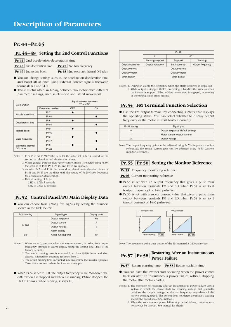
Pr. 55 Pr. 56
1440 pulse/sec. 1440 pulse/sec.
Out
put o
r di
spla
y
Out
put o
r di
spla
y
Output frequency Output current
Restarting After an InstantaneousPower Failure
Restart coasting time Restart cushion time
You can have the inverter start operating when the power comesback on after an instantaneous power failure without stoppingthe motor (the motor coasts).
Notes: 1. The operation of restarting after an instantaneous power failure uses asystem in which the motor starts by reducing voltage that graduallycushions the output voltage at the set frequency regardless of themotor’s coasting speed. This system does not detect the motor’s coastingspeed (the speed searching method).
2. When the instantaneous power failure stop period is long, restarting maynot always be smooth. See manual for details.
Pr.58Pr.57
Pr.58Pr.57
Description of Parameters
22
Shortest Acceleration/DecelerationMode Selection
Shortest acceleration/deceleration mode
When this parameter is selected, the inverter can be operatedeven when the acceleration/deceleration times are not set underthe same type of conditions as though appropriate values wereset for each parameter. This is a convenient operating modewhen you just need the settings to be approximately right.(Note1)
That the appropriate parameters are selected automatically.
Pr.60
Pr.60
Pr.57 setting Restarting possible
9999 (default) No
0 or 0.1–5 (Note) Yes
The coasting time is the time spent waiting for control to start, which is used forrestarting after recovery.Note: When Pr.57 is set to 0, the standard coasting time described below is set. You
can generally operate at this setting, but you can also adjust the time in therange of 0.1–5 seconds to better suit the inertial moment (GD2) of the loadand the size of the torque.
0.1–1.5K: 0.5 seconds2.2–7.5K: 1.0 second
Pr.59 settingOperation
Remotely set function Frequency settingmemory function (Note 1)
0 × –
1
2 ×
Note: When the RH-SD terminals or RM-SD terminals stay open for at least oneminute or when the start signal changes to OFF, the operating frequencysetting is placed in memory. If the power is turned off thereafter, operationresumes from this setting when power goes back on.
Remote Setting Function Selection By setting Pr.59 to 1 or 2, you can change the RH, RM, and RL
terminal functions to the acceleration, deceleration, clear setting,and same input functions of the remote setting box FR-FK.
Pr.59
Pr.57 (Coasting Time)
Pr.58 (Output Voltage Cushion Time)You can run the inverter using the default setting of 1 second forthis parameter, but you can also adjust the output voltagecushion time for restarting between 0 and 60 seconds to bettersuit the load specifications (the inertial moment and the size ofthe torque).
STF
STR
RH
RM
RL
SD
Forward
Reverse
Acceleration
Deceleration
Clear setting
Forward (STF)
Acceleration (RH)
Deceleration (RM)
Clear setting (RL)Maximum lengthof wiring is 30m
Example of Operation Example of connections
Note: The acceleration/deceleration time is the longerof the Pr.44/45 settings or the Pr.7/8 settings.
Out
put f
requ
ency
Pr.60 setting Function set Description of operation
Normal0 (default) operating – –
modeSet to accelerate/decelerate the motor in the shortesttime.The inverter makes acceleration/deceleration in the shortesttime using its full capabilities. During deceleration, aninsufficient brake capability may cause the regenerativeovervoltage alarm (E.OV3).
“1” : Stall prevention operation level 150%“2” : Stall prevention operation level 180%“11”: Stall prevention operation level 150%
when brake resistor or brake unit is used“12”: Stall prevention operation level 180%
when brake resistor or brake unit is used
Parameterautomatically
set
Shortestacceleration/deceleration
mode
(Note 2)
Pr.7(shortest),
Pr.8(shortest)
1, 2, 11, 12
Notes: 1. Set individual parameters when you need control suited to the applicationas well.
2. Accelerates in the shortest time regardless of the Pr.7 and 8 settings.
Notes: 1. When using this function, be sure to take precautions so that theoperator or machinery is not injured when the inverter automaticallystarts running after the retry wait time set with Pr.68.
2. A reset when restarting using the retry function does not clearaccumulated data, such as for the electronic thermal O/L relay andregenerative brake duty (which is not the case for a power supply reset).
Retry Selection
Retry selection
Number of retries at alarm occurrence
Retry waiting time
Retry count display erasure
Retry is a function in which the inverter automatically resets thealarm when an inverter alarm occurs and then restarts andcontinues operation.
Use Pr.65 to select the alarms for which a retry is done.
Pr.69
Pr.68
Pr.67
Pr.65
Pr.69Pr.68Pr.67Pr.65
Pr.67 setting Number of retries Alarm error signal output
0 (default) No retries –
1–10 1–10 Not output
01–110 1–10 Output
You can also set the number of retries when an alarm occurs withPr.67.
You can set the length of time to wait after an inverter alarmbefore restarting (0.1–360 sec.) using Pr.68.
You can find out how many retires were needed to successfullyrestart by reading Pr.69. When set to 0, the count is erased.
Pr.65 setting Retry type
0Retry for all alarms except fin overheating (FIN),PU disconnected (PUE), and CPU error (CPU).
1 Retry when an overcurrent cut-off (OCT) occurs.
2 Retry when a regenerative overvoltage cut-off (OVT) occurs.
3Retry when a regenerative overvoltage cut-off (OVT) orovercurrent cut-off (OCT) occurs.
Description of Parameters
23
Pr.66–Pr.77
See the description of Pr.22Pr.66
See the description of Pr.30Pr.70
Selecting Applied Motor When using a Mitsubishi constant torque motor, set Pr.71 to 1 for
both V/F control and general-purpose flux vector control. Theelectronic thermal is set to the constant torque motor thermalcharacteristics.
Pr.71
Input Filter Time Constant You can set the built-in input filter constant of the frequency
setting signal for the external voltage or current. This aids inremoving noise from the frequency setting circuit.
When noise prevents stable operation, increase the filter timeconstant. Increasing the setting will lower responsiveness.
Pr.74
Set 3, 13, 23, 103, 113, or 123 for off-line auto-tuning. When a number in the range 100–123is set, the electronic thermal switches to fixed torque thermal characteristics when the RTsignal goes ON.
Motor
Pr.71 setting Electronic thermal characteristicsStandard
Constanttorque
0, 100Thermal characteristics to matchgeneral-purpose motors (default)
1, 101Thermal characteristics for Mitsubishi constanttorque motor
2, 102 Standard motor
13, 113 Constant torque motor
Mitsubishi standard23, 123 motor SF-JR4P
(1.5 kW max.)
5, 105 Standard motor
15, 115 Fixed torque motor
6, 106 Standard motor
16, 116 Constant torque motor
Select “off-lineauto-tuningsetting”
Direct inputof motorconstantallowedDelta
wiring
Starwiring
Pr.240 setting Description
0 Soft-PWM control disabled
1 Soft-PWM control enabled
Changing Motor Noise
Select PWM frequency Set Soft-PWM
When the PWM carrier frequency is lowered, motor noiseincreases, but the noise generated from the inverter and theleakage current decrease.
Pr.72 can be set between 0 and 15; however, for 0, the value is0.7kHz, for 15 the value is 14.5kHz, and all other settings are theset value in kHz.
You can use Pr.240 to set whether to have Soft-PWM control,which changes the motor noise quality.
Pr.240Pr.72
Pr.240Pr.72
Note: This is only valid when Pr.72 (Set PWM frequency) is 0–5.
Notes: 1. When the RES signal goes ON during operation, the inverter cuts offthe output while the signal remains ON; the electronic overcurrentprotection and regenerative brake duty are reset, and the motor coaststo a stop.
2. When something other than a PU is connected (such as when doing RS-485 serial communications with a computer), no PU disconnections aredetected.
3. Input from the PU reset key is only accepted when protective functionsare engaged, regardless of the Pr.75 settings.
Reset Selection/Disconnected PUDetection/PU Stop Selection
This function sounds an alarm and stops the inverter with aninverter error when the inverter detects that a PU (control paneland parameter unit) connector has become disconnected fromthe inverter. You can select either a reset terminal function or afunction that decelerates to a stop when PU stop key is hit.
Pr.75
Pr.75 setting Reset signal PU disconnected PU stop selection
0 Input always accepted
1Input accepted only whenprotective function engaged
2 Input always accepted
3Input accepted only whenprotective function engaged
14Input always accepted
(default)
15Input accepted only whenprotective function engaged
16 Input always accepted
17Input accepted only whenprotective function engaged
Keeps operatingeven when PUdisconnected
Inverter outputcuts off when PUdisconnected
Keeps operatingeven when PUdisconnected
Inverter outputcuts off when PUdisconnected
Decelerates toa stop only whenPU stop key isentered in PUoperating mode
Stops when PUstop key isentered in alloperating modes(PU, external,communications,etc.).
Notes: 1. To change the maximum output frequency when inputting the maximumfrequency command voltage (current), set the frequency setting voltage(current) gain with Pr.903 (or Pr. 905). Since the acceleration /decelerationtime is the slope to the acceleration /deceleration reference frequency, itis not affected by changing the Pr.73 setting.
2. When operating the inverter while connected to a frequency meter, besure to set this value to 0.
Selecting the Frequency CommandVoltage Range
You can switch the input (terminal 2) specifications for thefrequency setting voltage signal. Be sure to set this when inputting0 to 10V DC.
Pr.73
Pr.73 setting Terminal 2 input voltage
0 DC 0–5V input (default)
1 DC 0–10V input
Notes: 1. Monitor-related Pr.54–56 can be set at any time.2. Pr.77 and 79 (operating mode selection) are write-enabled.3. Some parameters are write-disabled during operation. See the parameter list.
Parameter Write Disable Selection This parameter disables writing in control panel and parameter
unit functions.
Pr.77
Pr.77 setting Write disable function
0Parameter write enabled.(Only while stopped in PU mode. Default.)*1
1 Parameter write disabled.*2
2 Parameter write also enabled during operation.*3
Description of Parameters
24
Pr.78–Pr.96
Note: These settings are valid for both PU and external operation.
Reverse Rotation Prevention Selection Set this parameter to prevent problems caused by reverse
rotation caused by mistaken start signal input.
Pr.78
Operation by control panel and parameter unit is called “PU operation” in this table.
Operation Mode Selection The inverters have two operating modes: operation by external
signal and operation by PU (control panel and parameter unit).You can set this parameter to use either or both. The setting forthis parameter can be changed even when in external mode.
Pr.79
Note: Use Pr.180-183 (input terminal function selection) to assign the terminal thatthe X16 signal will use.
Pr.78 setting Rotation direction
0 Forward or reverse both allowed. (Default.)
1 Reverse disabled.
2 Forward disabled.
Setting Description
0You can change between PU operation mode and external operation
(default)mode using the keys of the control panel and parameter unit. See thecolumns for values 1 and 2 for the descriptions of the modes.
Operating mode Operating frequency Start signal
1 PU operating mode
2 External mode
External and PU3
operating mode
External and PU4
operating mode
6 Switchover mode
7 PU operation interlock
Switch operating mode external signal (can’t switch during operation)8 • PU operation is selected when X16 signal is OFF
• External operation is selected when X16 signal is ON
Set by control panelknob or digitally bycontrol panel orparameter unit key
Set by control panelknob or digitally bycontrol panel orparameter unit key,multi-speed selection
External signal input(between terminals2 (or 4) and 5, multi-speed selection)
External signal input(between terminals2 (or 4) and 5, multi-speed selection)
Control panel start(FWD and REV)keys or parameterunit FORWARD andREVERSE keys
Control panel start(FWD and REV)keys or parameterunit FORWARD andREVERSE keys
External signal input(STF and STRterminals)
External signal input(STF and STRterminals)
Note: In switchover mode, frequency cannot be set with the control panel knob(which is disabled).
Pr.79=6: Switchover ModeWhen set to switchover mode, you can change between PU and externaloperation at any time.
Switchover mode Switch
1 External operation to PU operation External mode data is brought into PU mode
2 PU operation to external operationWhen mode switches, the external knob valueand starting signal are used.
General-Purpose Flux Vector Control
Motor capacity
General-purpose flux vector control can be advantageous whenyou need a large starting torque or sufficient low-speed torque.Set the motor capacity. When using a constant torque motor,set Pr.71 (applied motor selection) to 1 or 13–16 (constant torquemotor).
Pr.80
Pr.80
Notes: General-purpose flux vector control can be used with the following restrictions.1. The motor is a standard, general-purpose squirrel-cage motor whose
capacity (0.1kW or higher) is equal to or less than the inverter capacity.In the fixed torque motor (SF-JRCA) 200V class 4P, it can be used with0.4–3.7kW motors.
2. The motor has 2, 4, or 6 poles. (Fixed torque motors must have fourpoles.) There is no need to set the number of poles.
3. The motor must be used alone (one inverter per motor). 4. The maximum wiring length between motor and inverter cannot exceed
30m. Beyond 30m, use off-line auto-tuning.Usage under other conditions may not provide the best performance.,
Note: This control system is not the same as the Mitsubishi advanced flux vectorcontrol used in the FR-A500 Series inverters.
Off-Line Auto-Tuning and Manual Setting ofMotor Constant
Motor excitation current
Rated motor voltage
Motor constant (R1)
Auto-tuning setting/status
You can automatically measure the motor constant to be usedwith general-purpose flux vector control with the auto-tuning(off-line) function.
After you select general-purpose flux vector control, set thefollowing parameters.
Pr.96
Pr.90
Pr.83
Pr.82
Pr.90,96Pr.83Pr.82
You can monitor the results of tuning with Pr.90. You can set the motor excitation current and motor constant with
Pr.82 and Pr.90. (See manual for details.)
Notes: 1. Motor shall be connected. When tuning starts, however, the motorshould be stopped.
2. You can do off-line auto-tuning even with a load (friction, constant load,etc.) on the motor.
3. You cannot tune special motors such as high-slip motors and high-speedmotors.
Pr. number Name Setting range
71 Applied motor 3, 13, or 23
83 Rated motor voltage 0–1000V
84 Rated motor frequency 0–400Hz
960 No off-line auto-tuning
1 Off-line auto-tuning without running the motor
Off-line auto-tuningsetting/status
Pr.79=7: PU Operation Interlock FunctionWhen set to PU operation interlock, PU operation can be interlocked as shownbelow by turning the MRS signal ON or OFF.
MRSsignal
External operation mode PU operation mode
ON Output stops PU operation enabled, parameter setting enabled.
OFFExternal operation Both PU operation and parameter setting disabled.enabled. Forcibly switched to external operation mode.
Description of Parameters
25
Note: These parameter settings are disabled during PU operation.
Note: Use parameters 190–192 (output terminal function selection) to assign theterminal that the output current detection signal (Y12) will use for output.
Pr.117–Pr.151
RS-485 CommunicationsOperation
Station number
Communication speed
Stop bit length/data length
Parity check presence/absence
Number of communication retries
Communication check time interval
Waiting time setting
CR/LF presence/absence selection
RS-485 communications can be performed from the inverter’s PUconnector.
Pr.124
Pr.123
Pr.122
Pr.121
Pr.120
Pr.119
Pr.118
Pr.117
Pr.117–124
PID Control
PID action selection Lower limit
PID proportional band PID action set point
PID integral timefor PU operation
Upper limit PID differential time
Use these for process controls of flow, airflow, pressure, etc.Quantities provided externally as voltage or digital values areused as the settings; PID control is performed with 4–20mAcurrent input signals as the feedback quantities.
Pr.134Pr.131
Pr.130
Pr.133Pr.129
Pr.132Pr.128
Pr.128–134
For RS-485 communication, set the following parameters. (See manual for details.)
IMPIDoperation+
-
Measured value (4~20mA)
Setting(voltage or digital value) Inverter
drivecircuit
Current Detection
Output current detection level
Output current detection period
When the output current exceeds the level set in Pr.150 (outputcurrent detection level) and the time set in Pr.151 (output currentdetection time) elapses, the output terminal goes ON. Oncethe output signal goes ON, it stays ON for at least 100ms(approximately).
Pr.151
Pr.150
Pr.151Pr.150
OFF ON
100ms
OFF
Pr. 150
Pr. 151
Output current detectionsignal (Y12)
Out
put c
urre
nt
Time
Switch Parameter Unit Language You can switch the language that the parameter unit uses. This
setting is enabled when the optional FR-PU04 unit is used.
Pr.145
Select Frequency SettingInstruction
Select whether to set the frequency using the control panel knobor digitally using the keys.
Pr.146
Pr. number Name Setting Description
117 Local station 0-31 Set inverter station number
48 4800 baud
118 96 9600 baud
192 19200 baud
0 1 stop bit, 8 data bits
1191 2 stop bit, 8 data bits
10 1 stop bit, 7 data bits
11 2 stop bit, 7 data bits
0 No parity check
120 1 Odd parity
2 Even parity
0–10Set permitted No. of retries for
121 communications errors
9999 Do not check for communications errors
0 Communication disabled
122 0.1–999.8 Set communication time interval (in seconds)
9999 Halt communication check
1230–150 Set send wait time (in ms)
9999 Set send wait time in communication
0 No CR or LF
124 1 Only CR
2 Both CR and LF
Communicationspeed
Stop bit length/data length
No. of paritychecks
Number ofcommunicationretries
Communicationcheck timeinterval
Waiting timesetting
CR/LF presence/absenceselection
Pr.146 setting Select frequency setting
0 Built-in frequency setting control volume
1 Digital frequency setting using the keys
Frequency setting using the built-in frequency setting control9999 volume is available when the frequency setting has been set at
(OH2) using the keys
Pr.145 setting Language
0 Japanese (default)
1 English
2 German
3 French
4 Spanish
5 Italian
6 Swedish
7 Finnish
*CC-Link type does not have this function.
Description of Parameters
26
Pr.152–Pr.192
Stall Prevention Operation Selection This selects how the stall prevention and high-response current
limit function work.
Pr.156
Note: Use Pr.190–192 (output terminal function selection) to assign the terminalthat the zero current detection signal (Y13) will use for output.
Note: There are other settings than the above. See manual for details.
Zero Current DetectionSignals
Zero current detection level
Zero current detection period
When the output current falls below the level set in Pr.152 (zerocurrent detection level) and the time set in Pr.153 (zero currentdetection time) elapses, the output terminal goes ON. The outputsignals stays ON for about 100ms even after conditions change.
Pr.153
Pr.152
Pr.153Pr.152
OFF ON
100ms
OFF
Pr. 152
Pr. 153
Output current detectionsignal (Y13)
Out
put c
urre
nt
Time
Pr.156 setting Stall prevention and high-response current limit function operation
0 Operates (default)
100 Does not work during regenerative operation.
Input Terminal FunctionSelection
RL terminal function selection
RM terminal function selection
RH terminal function selection
MRS terminal function selection
Functions can be freely assigned to input terminals by setting0–18 for Pr.180–Pr.183.
Pr.183
Pr.182
Pr.181
Pr.180
Pr.180–183
Pr.160=0001
1 User group 1 (0: Disabled, 1: Enabled)2 User group 2 (0: Disabled, 1: Enabled)
User Group Selection
User group read selection User group 2 registration
User group 1 registration User group 2 deletion
User group 1 deletion
Up to 32 of the parameters can be registered in two user groups.The registered parameters can be read and written. When a usergroup is selected with Pr.160 (user group selection), unregisteredparameters cannot be read.
Pr.174
Pr.176Pr.173
Pr.175Pr.160
Pr.173–176Pr.160
Registering Parameters in a User Group:Write the parameter number to be registered in Pr.173 (usergroup 1 registration) or Pr.175 (user group 2 registration).
Deleting Parameters from a User Group:Write the parameter number to be deleted in Pr.174 (user group1 deletion) or Pr.176 (user group 2 deletion).
Actual Operation Hour Meter Clear Write 0 to clear the actual operation time monitor (Pr.52=23).
Pr.171
Note: The functions of the STF, STR, and RES terminals cannot be changed.
Output Terminal FunctionSelection
RUN terminal function selection
FU terminal function selection
A, B, C terminal function selection
Set Pr.190–Pr.192 to 0–99 or 9999 to freely assign functions to theoutput terminals (including relays)
Pr.192
Pr.191
Pr.190
Pr.190–192
Setting Terminal Terminal function
0 RL Low speedRemote setting(clear settings)
1 RM Pr.59=0 Middle speed Pr.59=1Remote setting(deceleration)
2 RH High speedRemote setting(acceleration)
3 RT Second function selection
4 AU Current input selection
5 STOP Start self-hold selection
6 MRS Stop output
7 OH External thermal input
8 REX 15 speed setting (combination of 3 speeds, RL, RM, and RH)
16 X16 Switch between PU operation to external operation
18 X18 Switch between V/F to general-purpose flux vector control
Pr. number Name Terminal
180 RL terminal function selection RL
181 RM terminal function selection RM
182 RH terminal function selection RH
183 MRS terminal function selection MRS
Pr. number Name Terminal
190 RUN terminal function selection RUN
191 FU terminal function selection FU
192 A, B, C terminal function selection A, B, C
Setting Terminal Terminal function
0 RUN Inverter running
1 SU Reach frequency
3 OL Overload warning
4 FU Frequency detection
11 RY Inverter ready to run
12 Y12 Output current detection
13 Y13 Zero current detection
14 FDN PID minimum
15 FUP PID maximum
16 RL PID forward reverse output
98 LF Minor breakdown output
99 ABC Error output
Description of Parameters
27
Fan ON-OFF Control Controls the cooling fan.
Pr.244
See the description of Pr.4Pr.232–239
Pr.247 setting Function
0 No slip compensation in constant output zone.
9999 Slip compensation in constant output zone.
Rated slip= ×100%Base frequency synchronization speed – rated RPM
Base frequency synchronization speed
Notes: 1. Decreasing this value increases the response time but also makesregenerative overvoltage errors (OVT) more frequent, for example,when there is greater load inertia.
2. There is no slip compensation when Pr.245 is set to 9999.
Notes: 1. When parameter 249 is 1 and a ground fault is detected, error indicator“E.GF” is displayed and output cuts off.
2. The protective function does not engage for ground faults that occurwhile the inverter is running.
3. If the motor capacity is less than 100W, ground fault protection may notbe available.
4. This parameter is not applicable to the FR-E540 series.
When Pr.250 is 1000–1100 seconds, the STF and STR terminal functions are the same aswhen Pr.250 is 8888. It will stop while the start signal is OFF by cutting off output (coastingto a stop) after (Pr.250 setting)–1000 seconds.
Pr.232–Pr.991
Stop Selection This parameter selects the stopping method used when the start
signal goes OFF (decelerating stop or coasting stop).
When Pr.250 is 9999 (decelerating stop when start signal goes OFF):
Pr.250
FM Terminal Output Calibration You can use the control panel to calibrate meters connected to
the FM terminal. This calibration function is shared by all monitorfunctions selected with Pr.54.
The FM terminal output is pulse output like that shown in thediagram below. You can set Pr.900 so you can use the controlpanel for scale calibration of meters connected to the inverterwithout having to install a scale calibrating resistor. (See the manual for more information about calibration.)
Pr.900
Notes: 1. When Pr.250 is something other than 9999, the RUN signal goes OFFwhen the start signal goes OFF.
2. When the restart signal goes ON while the motor is coasting, the motorstarts from 0Hz.
3. When Pr.250 is 0, the cut-off of output is the within the shortest time.
ON OFF
DC braketime
Start signal
Out
put f
requ
ency
Decelerating stopwhen start signal goes OFF
Decelerating time (Pr.8)
ON OFF
Pr. 250
Time
Start signal
Out
put f
requ
ency
Output cuts off after set timewhen start signal goes OFF
Motor coast to a stop
When Pr.250 is 0–100 (coasting stop when start signal goes OFF):
When Pr.250 is 8888, the terminal STF and STR functions switch as follows.(STF: Start signal, STR: Rotation direction signal)
STF STR Inverter Operating Status
OFF OFF Stop
OFF ON Stop
ON OFF Forward
ON ON Reverse
–+
1mAFM
SDT2
T1
DC8V
Display meter.1mA full scale analog meter.( )
Pulse width T1: Adjust with Pr.900Pulse period T2: Set with Pr.55
(valid only with frequency monitor)
Check for Ground Faults at Startup You can choose whether to check for ground faults at startup.
Ground faults can only be implemented immediately after thestart signal is input to the inverter.
Pr.249
Slip Compensation
Rated motor slip
Slip compensation response time
Constant-output region slip compensation selection
The motor slip can be estimated from the inverter output currentand the motor rotation held constant.
Pr.247
Pr.246
Pr.245
Pr.245–247
Pr.247 selects whether or not to activate slip compensation in the rated output zone(the frequency zone above the frequency set in Pr.3).
Pr. number Name Description Default
245 Rated motor slip Sets the rated slip of the motor 9999
246Slip compensation response Sets the response time for sliptime compensation.(Note 1) 500ms
Pr.249 setting Description
0 Don’t detect ground faults (default)
1Detect ground faults. Output is delayed about 20ms at every startupwhen ground faults are checked.
Pr.244 setting Fan operation
0 No ON-OFF control (Factory setting)
1ON-OFF control (Always ON during inverter operation; while theinverter is stopped, goes ON-OFF according to temperature control.)
Description of Parameters
28
Frequency Setting Signal Gain and Bias Adjustment
Frequency setting voltage bias
Frequency setting voltage gain
Frequency setting current bias
Frequency setting current gain
Built-in knob bias
Built-in knob gain
You can set any size (slope) of output frequency for the frequencysetting signal (0 to 5V, 0 to 10V, or 4–20mA DC) and controlpanel knob setting.
Input between inverter terminals 2 and 5 (0 to 5V, 0 to 10V DC)or terminals 4 and 5 (4–20mA DC) or calibrate by turning thecontrol panel knob to any position.
Set Pr.902–Pr.905 to some setting other than the digital frequencysetting 0.00. Set Pr.922 and Pr.923 to the digital frequency setting0.00 in PU operating mode and calibrate when operation by theknob is selected.
Pr.923
Pr.922
Pr.905
Pr.904
Pr.903
Pr.902
Pr.922–923Pr.902–905
Note: Set before shipment so that 1mA provides full scale and a FM outputfrequency of 1440Hz at 60Hz.
Notes: 1. When Pr.903 and Pr.905 are set, the 5V input frequency (Pr.38) and20mA input frequency (Pr.39) are automatically overwritten.
2. An error will result if the differences between Pr.902 and Pr.903, Pr.904and Pr.905, or Pr.922 and Pr.923 exceed 5% of the maximum input.
–+FM
SD
Digital display meter
Pulses/sec.
Buzzer Sound Control You can turn the buzzer sound used when parameter unit FR-
PU04 keys are pressed either on or off.
Pr.990 Monitoring Using Digital Display MeterYou can display data digitally using a digital counter byemploying the pulse train output of the FM terminal. Output is1440 pulse/sec. at the full scale value described in the section onPr.54. When operating frequency is selected for monitoring, youcan set the FM output frequency for this terminal using Pr.55.
Pr. 902
Pr. 904
Pr. 922
Pr. 903
Pr. 905
Pr. 923
0 V1 V2 5V (10V)
Calibrating by applying a voltageExample: Apply V1(V) between terminals 2 and 5 to
set the bias and apply V2(V) to set the gain.
Output frequency(Hz)
Frequency setting signal
Gain
To calibrate without inputting a voltage or current, set a frequencyin Pr.38 (5V (10V) input frequency) or Pr.39 (20mA inputfrequency). When Pr.38 is set, the values of Pr.902 and Pr.903 areno longer valid; when Pr.39 is set, the values of Pr.904 and Pr.905are no longer valid.
Pr.990 setting Description
0 No buzzer
1 Buzzer (default)
LCD Contrast You can adjust the contrast of the LCD on the optional FR-PU04
parameter unit.
Pr.991
Note: The LCD contrast setting will not be recorded unless you press the [WRITE]key.
Pr.991 setting Description
Bright
0 to 63 53 (default)
Dark
Protective Functions
29
The following protective functions are provided for the protection of the inverter itself (except for the motor's electronic thermal relay), but theymay also function when the inverter breaks down.
Accelerating
Constant speed
Decelerating
Accelerating
Constant speed
Decelerating
Function name Description Display
Type (Note 5)
Majorfault
Minorfault
(OC1)
(OC2)
(OC3)
(OV1)
(OV2)
(THM)
(THT)
(FIN)
(OHT)
(OPT)
(GF)
(BE)
(PE)
(FN)
(OV3)
Overload shut-off(electronic thermal relay) (Note 1)
Fin overheat
Fan breakdown
If the cooling fin overheats, the fin overheat sensor activates and halts inverter output.
Parameter error Generated when an error occurs in a stored parameter (e.g. E2ROM breakdown).
Number of retries exceeded When operations cannot be restarted normally within the set number of retries, inverter output is halted.
(PUE)
(RET)
(LF)
PU disconnected
Motor
Inverter
Over-current shut-off
Regenerative overvoltageshut-off
When the inverter output current exceeds the rated current by more than approximately 200% during acceleration/deceleration or at constant speed, the protective circuit activates, halting inverter output.
If the DC voltage in the inverter's internal main circuit exceeds the rated value as a result of regenerative energy generated through motor braking during acceleration/deceleration or at constant speed, the protective circuit activates, halting inverter output. There are also cases where it is activated by surge voltage generated in the power supply system.
The electronic overcurrent protection inside the inverter detects motor overheating resulting from overloading or a decline in cooling capacity at constant speed, activating the protective circuit and halting inverter output. The electronic thermal relay cannot protect multipolar and other special motors, or several motors working together, so a thermal relay should be installed on the inverter's output side.
In the case where a current flows that is at least 150% of the rated output current but does not exceed the overcurrent shut-off (OC) level (200% max.), the electronic thermal relay activates according to reverse time characteristics to protect the main circuit transistors, and halts inverter output. (150% of overload capacity, 60 seconds.)
When the inverter has a built-in cooling fan, FN will be displayed on the control panel when the cooling fan breaks down or an operation different from the setting of Pr.244 (cooling fan operation selection) is performed. Inverter output does not stop.
Output ground fault overcurrent protection
When a ground fault occurs at the inverter output (the load side) when the inverter is started up and the ground fault overcurrent flows, inverter output stops. Use Pr.249, “Ground fault detection at Startup (Y/N)” to set whether to engage the protection function. (Note 8)
External thermal relay operation (Note 2)
When an externally installed motor overheating protective thermal relay or temperature relay within the motor, etc., activates (relay contact open), the inverter can be stopped if the contact is input to the inverter. Even if the relay contact resets automatically, the inverter will not restart unless it is reset also.
Brake transistor errordetected (Note 3)
When the optional brake resistor is connected and a brake transistor error occurs (for example, when the energy regenerated from the motor becomes very large), this is judged a brake transistor error and inverter output stops.
Inverter output halts when communication between the main unit and the PU is interrupted by disconnection of the PU, etc., when Pr. 75 is set to 2, 3, 16, 17.
If the built-in CPU does not complete operations within the prescribed time, it self-diagnoses a fault and halts inverter output.
When a current of 150% (Note 4) or more of the inverter's rated current flows in the motor, the rise in frequency is stopped until the load current declines, preventing the inverter from executing an over-current shut-off. The frequency is increased again once the current falls below 150% of the rated value.
Output phase loss detection Detects when the inverter looses an output phase (U, V or W).
(CPU)
(OLT)
CPU error
Current limit/Stall prevention
Optional equipment error (Note 7)
During acceleration
When a current of 150% (Note 4) or more of the inverter's rated current flows in the motor, the frequency is lowered until the load current declines, preventing the inverter from executing an over-current shut-off. The frequency is restored to the set level once the current falls below 150% of the rated value.
Checks for breaks in the CC-Link connection cable. This protection function also engages when reset with the master unit in NET mode (Pr. 79 = 2). (Inverters are set to NET mode when shipped.)
If the motor's regenerative energy is excessive and surpasses its braking capacity, the decline in frequency is halted, preventing the inverter from executing an over-current shut-off. Once the regenerative energy has declined, deceleration continues. When a current of 150% (Note 4) or more of the inverter's rated current flows in the motor, the decline in frequency is halted until the load current declines, preventing the inverter from executing an over-current shut-off. The frequency is lowered once again once the current falls below 150% of the rated value.
At constant speed
During deceleration
and monitor displayed alternately.
and monitor displayed alternately.
and monitor displayed alternately.
Notes: 1. When the inverter is reset, the internal heat counting data in the electronic thermal O/L relay (overcurrent protection) is initialized.2. External thermal relay operations are only performed when Pr. 180–Pr. 183 (input terminal function selection) is set to OH.3. This only functions when the optional brake resistor is connected.4. Any stall prevention operation current can be set. Set to 150% when shipped.5. Major Breakdowns: Inverter output is cut off by the protection function and an error signal is output.
Minor Breakdowns: The protection function does not cut off output. A minor breakdown signal can be output if the parameter is set to do so.6. In the case of the CC-Link Series, the ALARM lamp lights up the when the protection function activates. If parameter unit FR-PU04 is in use, its displays switches
automatically to indicate an error.7. CC-Link Series only.8. Pr.249 is not applicable to the FR-E540 series.
The FR-E540 series is automatically set to detect ground faults.
Alarm output signal held........When the magnetic contactor (MC) provided on the power supply side of the inverter is opened at the activation of the protective function,the inverter's control power will be lost and the alarm output will not be held.
Alarm display..........................When the protective function is activated, the control panel display automatically switches to the above indication. Resetting method....................When the protective function is activated, the inverter output is kept at a stop. Therefore, unless reset, the inverter cannot restart. Switch
power off once, then on again; or short reset terminal RES-SD for more than 0.1 second, then open. If RES-SD are kept shorted, "Err." appears(flickers) to indicate that the inverter is being reset.
Connection Examples
30
Basic Wiring Diagram (Operation by External Signal)
This is the basic inverter wiring diagram when operating by usingforward and reverse switches, an external potentiometer etc.
For safety, install a magnetic contactor on the input side.
Notes: 1. To install the model MRS optional external brake resistor to increasebraking power, connect it between terminals PR and P (+).
2. Set Pr. 54 to be able to select an output current display rather thanfrequency.
3. Since Pr. 900 can be used to calibrate the scale of the display meter,there is no need for a scale calibration resistor except when remotecalibration is required.
Basic Wiring Diagram (Main Circuit Input Cut-Off by Alarm)
This is the circuit when cutting off the main inverter circuit inputwith a magnetic contactor when an inverter alarm stop occurs.
The terminal FM-SD output can be either a frequency or a motorcurrent signal. (See the description of Pr. 54 on page 21 fordetails.)
For reset input, you can also select a function (error reset) thataccepts signals only when the inverter alarm stops. (See thedescription of Pr. 75 on page 23 for details.)
IM
R (L1)
MCNFB
Power supplyS (L2)
T (L3)
U
V
W
PR
(+)P
N(–)
STF
STR
RES
SD
10(5V)
2
5
A
B
C
FM
SD
E500LED display
Inverter
Motor
(Note 1)
Forward
Reverse
Reset
Frequency meter1/2W1kΩ
Error output (operates during errors)
(Note 3)Scale calibrationresistor
(Note 3)Multi-function display meter output (1mA full scale)
IM
R (L1)
MCPower supply
S (L2)
T (L3)
U
V
W
P
P1
N N
HC
HB
HA
STF (forward when closed)
C
B
STR (reverse when closed)
RES (Resets when closed)
SD
20–5 V/0–10V input (input resistance 10kΩ)
10 (5V)
5
E500LED display
CR1
HB HC
F
01X 01Y
Forward start
Reverse start
Reset
Frequencymeter
1/2W1kΩ
Inverter
Motor
Inverter alarm(opens when alarm occurs)(inverter trips)
200/100 Tr
Brake unit FR-BUResistorunit
CR2
MC
Error reset
CR1
Stop
Preparingfor operation
MC
CR2
CR2
MC
R
01X 01Y
Inverter error
Inverter error lamp
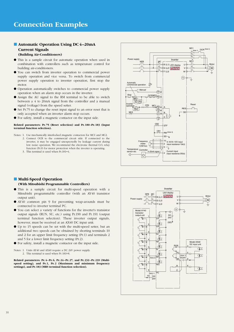
31
Connection Examples
Automatic Operation Using DC4–20mACurrent Signals(Building Air-Conditioners)
This is a sample circuit for automatic operation when used incombination with controllers such as temperature control forbuilding air-conditioners.
You can switch from inverter operation to commercial powersupply operation and vice versa. To switch from commercialpower supply operation to inverter operation, first stop themotor.
Operation automatically switches to commercial power supplyoperation when an alarm stop occurs in the inverter.
Assign the AU signal to the RM terminal to be able to switchbetween a 4 to 20mA signal from the controller and a manualsignal (voltage) from the speed setter.
Set Pr.75 to change the reset input signal to an error reset that isonly accepted when an inverter alarm stop occurs.
For safety, install a magnetic contactor on the input side.
Related parameters: Pr. 75 (Reset selection) and Pr. 180–Pr. 183 (Inputterminal function selection).
Notes: 1. Use mechanically interlocked magnetic contactors for MC1 and MC2.2. Connect OCR to the commercial circuit side. If connected to the
inverter, it may be engaged unexpectedly by leakage current duringlow noise operation. We recommend the electronic thermal O/L relayfunction (Pr.9) for motor protection when the inverter is operating.
3. This terminal is used when Pr.181=4.
Multi-Speed Operation (With Mitsubishi Programmable Controllers)
This is a sample circuit for multi-speed operation with aMitsubishi programmable controller (with an AY40 transistoroutput unit).
AY40 common pin 9 for preventing wrap-arounds must beconnected to inverter terminal PC.
You can select a variety of functions for the inverter's transistoroutput signals (RUN, SU, etc.) using Pr.190 and Pr.191 (outputterminal function selection). These inverter output signals,however, must be received at an AX40 DC input unit.
Up to 15 speeds can be set with the multi-speed setter, but anadditional two speeds can be obtained by shorting terminals 10and 2 for an upper limit frequency setting (Pr.1) and terminals 2and 5 for a lower limit frequency setting (Pr.2).
For safety, install a magnetic contactor on the input side.
Notes: 1. Units AY40 and AX40 require a DC 24V power supply.2. This terminal is used when Pr.183=8.
Related parameters: Pr. 4–Pr. 6, Pr. 24–Pr. 27, and Pr. 232–Pr. 239 (Multi-speed setting), and Pr.1, Pr. 2 (Maximum and minimum frequencysettings), and Pr.183 (MRS terminal function selection).
IMLED display
MC2
MC1
CR1
CR2
CR3
RT
Power supplyNFB MC
MC1
MC2
OCR
U
V
W
R (L1)
S (L2)
T (L3)
A
B
C
RES
SD
STF
RM (Note 3)
SD
10
2
5
4
CR1
CR2
MC2
MC2
MC2
MC1
MC1
CR3
RTCR3
OCR
F
Manual
Automatic commercial operation
Stop
Inverteroperation
Frequencymeter
1/2W1kΩTemperaturesensor etc.
Controller4–20mA signal
Inverter
(Note 3)(Note 1)
0–5V/0–10V input (input resistance 10kΩ)
Current input (input resistance 250Ω)
Motor
Reset
IM
LED display
Power supply
NFB MCU
V
W
R (L1)
S (L2)
T (L3)
STF1
STR2
RH3
RM4
RL5
MRS6
4RUN
5FU
9
6
SE
B
C
RES
PC
7
9
10 DC24V
DC24V
(SD)
DC24V
Model AY40 transistor output unit
(Note 1)
(Note 2)
(Note 1)
Inverter
Motor
Model AX40 DC input unit

32
Peripherals
Selecting Peripherals
Voltage Applicable inverters Magnetic contactors (MC)Motor output
(kW)No-fuse breaker (NFB)
or leakage breaker (NV)Lead (mm2)
R, S, T (L1, L2, L3) U, V, W
0.1
0.2
0.4
0.75
1.5
2.2
3.7
5.5
7.5
0.4
0.75
1.5
2.2
3.7
5.5
7.5
0.1
0.2
0.4
0.75
0.1
0.2
0.4
0.75
FR-E520-0.1K(N)
FR-E520-0.2K(N)
FR-E520-0.4K(N)
FR-E520-0.75K(N)
FR-E520-1.5K(N)
FR-E520-2.2K(N)
FR-E520-3.7K(N)
FR-E520-5.5K(N)
FR-E520-7.5K(N)
FR-E540-0.4K
FR-E540-0.75K
FR-E540-1.5K
FR-E540-2.2K
FR-E540-3.7K
FR-E540-5.5K
FR-E540-7.5K
FR-E520S-0.1K
FR-E520S-0.2K
FR-E520S-0.4K
FR-E520S-0.75K
FR-E510W-0.1K
FR-E510W-0.2K
FR-E510W-0.4K
FR-E510W-0.75K
Models NF30 and NV30 5A
Models NF30 and NV30 5A
Models NF30 and NV30 5A
Models NF30 and NV30 10A
Models NF30 and NV30 15A
Models NF30 and NV30 20A
Models NF30 and NV30 30A
Models NF50 and NV50 50A
Models NF100 and NV100 60A
Models NF30 and NV30 5A
Models NF30 and NV30 5A
Models NF30 and NV30 10A
Models NF30 and NV30 15A
Models NF30 and NV30 20A
Models NF30 and NV30 30A
Models NF50 and NV30 40A
Models NF30 and NV30 5A
Models NF30 and NV30 10A
Models NF30 and NV30 10A
Models NF30 and NV30 15A
Models NF30 and NV30 10A
Models NF30 and NV30 15A
Models NF30 and NV30 20A
Models NF30 and NV30 30A
AC supply-coordinatingreactor
FR-BAL-0.4K (Note 5)
FR-BAL-0.4K (Note 5)
FR-BAL-0.4K
FR-BAL-0.75K
FR-BAL-1.5K
FR-BAL-2.2K
FR-BAL-3.7K
FR-BAL-5.5K
FR-BAL-7.5K
FR-BAL-H0.4K
FR-BAL-H0.75K
FR-BAL-H1.5K
FR-BAL-H2.2K
FR-BAL-H3.7K
FR-BAL-H5.5K
FR-BAL-H7.5K
FR-BAL-0.4K (Note 5)
FR-BAL-0.4K (Note 5)
FR-BAL-0.4K (Note 5)
FR-BAL-0.75K (Note 5)
FR-BAL-0.4K (Note 5)
FR-BAL-0.4K (Note 5)
FR-BAL-0.4K (Note 5)
FR-BAL-0.75K (Note 5)
DC supply-coordinatingreactor
FR-BEL-0.4K (Note 5)
FR-BEL-0.4K (Note 5)
FR-BEL-0.4K
FR-BEL-0.75K
FR-BEL-1.5K
FR-BEL-2.2K
FR-BEL-3.7K
FR-BEL-5.5K
FR-BEL-7.5K
FR-BEL-H0.4K
FR-BEL-H0.75K
FR-BEL-H1.5K
FR-BEL-H2.2K
FR-BEL-H3.7K
FR-BEL-H5.5K
FR-BEL-H7.5K
FR-BEL-0.4K (Note 5)
FR-BEL-0.4K (Note 5)
FR-BEL-0.4K (Note 5)
FR-BEL-0.75K (Note 5)
S-N11
S-N18
S-N18
S-N18
S-N21
S-N18
S-N18
S-N21
S-N21
S-N18
S-N21
S-N21
S-N21
S-N18
S-N20
S-N21
S-N21
S-N25
S-N11, S-N12
S-N20
S-N25
S-N35
S-N10
S-N10
S-N10
S-N20
S-N20
S-N20
S-N20
S-N20
S-N21
S-N25
S-N25
S-N21
S-N25
S-N25
S-N25
S-N20
S-N20
S-N21
S-N21
S-K50
S-N20
S-N21
S-K50
S-K50
S-N21
S-N25
S-K50
S-K50
2
2
2
2
2
2
3.5
5.5
14
2
2
2
2
2
3.5
3.5
2
2
2
2
2
2
2
2
2
2
2
2
2
2
3.5
5.5
8
2
2
2
2
2
2
3.5
2
2
2
2
2
2
2
2
3-phase200V
3-phase400V
Single-phase200V
Single-phase100V
—
—
—
—
Notes: 1. Select the appropriate NFB model for your power supplycapacitance.
2. The lead size shown is for a wiring length of 20m.3. Selection of the magnetic contactor at the inverter input side
will differ in the areas A, B, and C (as shown in the rightdiagram) because of the power supply capacitance and wiringlength. For 0.4K to 1.5K, select an S-N10 when using a reactorfor improving the power factor (FR-BEL or FR-BAL).
4. When the inverter capacity exceeds the motor capacity, selectthe breaker and magnetic contactor appropriate for the invertermodel and select the lead and reactor for improving the powerfactor appropriate for the motor model.
5. There are occasions where goes slightly under 0.9. Note: This is for when the recommended lead size is used.
Selecting the Rated Sensitivity Current of theLeakage Breaker
If you are using a leakage breaker in the inverter circuit, use thefollowing criteria to select a rated sensitivity current, regardless ofthe carrier frequency.•For the Progressive Super NV Series (models SP and CP): Rated sensitivity current I n>10× (Ig2+Ign+Ig2+Igm)
•For the conventional NV series (models CA, CS, and SS):Rated sensitivity current I n>10Ig1+Ign+3×(Ig2+Igm)
Ig1, Ig2: Leakage current when operating with a cable run offa commercial power supply.
Ign*: Leakage current of noise filter on inverter input side.Igm: Leakage current when operating a motor off a with
commercial power supply.
IM
5.5mm2 70m×5.5mm2 5m×
NV
200V 2.2kwInverter
Noise filter
Example
Notes: 1. Install the NV on the primary side of the inverter the (power supply side).2. Ground detection on the inverter's secondary side is possible if the
operating frequency is 120Hz or less.3. If you are using the W connection neutral point grounding method, the
sensitivity current of the grounding at the inverter's secondary side willslow down, so use a special class 3 ground (10Ω or less) for theprotection ground of the equipment under load.
* Consult the filter manufacturer for the leakage current value of the noisefilter installed at the inverter input side. (See pages 37 for the Mitsubishiinverter filters.)
120
100
80
60
40
20
01.25 2 3.5 5.5 8 14 22
30 60 10038 80 150
1.00.70.5
0.3
0.2
0.10.070.05
0.030.02
0.1 0.2 0.4 0.75 1.5 2.2 3.7 10
Leak
age
curr
ent (
mA
)
Leak
age
curr
ent (
mA
)
Lead size (mm2) Motor capacity (kW)
Example of leakage currents per 1kW in cable path duringcommercial power supply operationwhen the CV cable is routed inmetal conduit (200V 60Hz)
Example of leakage currents for operating a 3-phaseinduction motor off acommercial power supply(200V 60Hz)
ProgressiveSuper NV Series
Conventional NV
33 × = 0.1770m1000m
33 × = 2.3170m1000m
Leakage current (Ig1)
Leakage current (Ig2)
Leakage current (Ign)
Motor leakage current (Igm) 0.18
Total leakage current 2.66 7.64
Rated sensitivity current (>Ig×10) 30 100
0 (without noise filter)
Examples of Selections (Based on Figure Above)
∇
∇
50
500
C
B A
0 10 20Pow
er s
uppl
y ca
paci
tanc
e (k
VA
)
Setting range for reactor to improve power factor
Wiring length (m)
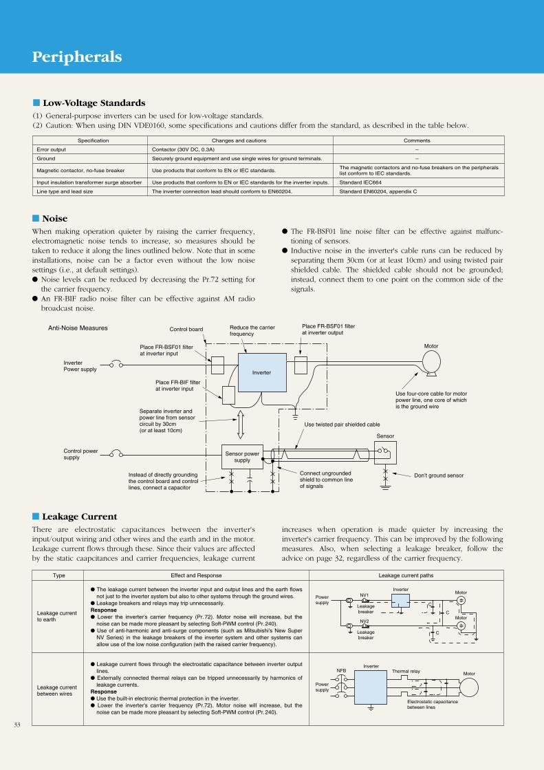
33
Peripherals
NoiseWhen making operation quieter by raising the carrier frequency,electromagnetic noise tends to increase, so measures should betaken to reduce it along the lines outlined below. Note that in someinstallations, noise can be a factor even without the low noisesettings (i.e., at default settings). Noise levels can be reduced by decreasing the Pr.72 setting for
the carrier frequency. An FR-BIF radio noise filter can be effective against AM radio
broadcast noise.
The FR-BSF01 line noise filter can be effective against malfunc-tioning of sensors.
Inductive noise in the inverter's cable runs can be reduced byseparating them 30cm (or at least 10cm) and using twisted pairshielded cable. The shielded cable should not be grounded;instead, connect them to one point on the common side of thesignals.
InverterPower supply
Control powersupply
Place FR-BSF01 filterat inverter input
Place FR-BIF filter at inverter input
Separate inverter and power line from sensor circuit by 30cm (or at least 10cm)
Instead of directly grounding the control board and control lines, connect a capacitor
Control board Reduce the carrier frequency
Inverter
Sensor powersupply
Place FR-BSF01 filter at inverter output
Use twisted pair shielded cable
Connect ungrounded shield to common line of signals
Sensor
Don’t ground sensor
Motor
Use four-core cable for motor power line, one core of which is the ground wire
Anti-Noise Measures
Leakage CurrentThere are electrostatic capacitances between the inverter'sinput/output wiring and other wires and the earth and in the motor.Leakage current flows through these. Since their values are affectedby the static caapcitances and carrier frequencies, leakage current
increases when operation is made quieter by increasing theinverter's carrier frequency. This can be improved by the followingmeasures. Also, when selecting a leakage breaker, follow theadvice on page 32, regardless of the carrier frequency.
Type
Leakage currentto earth
Leakage currentbetween wires
Effect and Response Leakage current paths
The leakage current between the inverter input and output lines and the earth flows not just to the inverter system but also to other systems through the ground wires.
Leakage breakers and relays may trip unnecessarily.Response Lower the inverter’s carrier frequency (Pr.72). Motor noise will increase, but the
noise can be made more pleasant by selecting Soft-PWM control (Pr.240). Use of anti-harmonic and anti-surge components (such as Mitsubishi's New Super
NV Series) in the leakage breakers of the inverter system and other systems can allow use of the low noise configuration (with the raised carrier frequency).
Leakage current flows through the electrostatic capacitance between inverter output lines.
Externally connected thermal relays can be tripped unnecessarily by harmonics of leakage currents.
Response Use the built-in electronic thermal protection in the inverter. Lower the inverter's carrier frequency (Pr.72). Motor noise will increase, but the
noise can be made more pleasant by selecting Soft-PWM control (Pr.240).
NV1
NV2
C
C
C
Power supply
Power supply
Leakagebreaker
Leakagebreaker
Inverter
InverterInverter
Motor
Motor
MotorNFB Thermal relay
Electrostatic capacitance between lines
Inverter
Low-Voltage Standards (1) General-purpose inverters can be used for low-voltage standards.(2) Caution: When using DIN VDE0160, some specifications and cautions differ from the standard, as described in the table below.
Specification Changes and cautions Comments
Error output Contactor (30V DC, 0.3A) –
Ground Securely ground equipment and use single wires for ground terminals. –
Magnetic contactor, no-fuse breaker Use products that conform to EN or IEC standards.The magnetic contactors and no-fuse breakers on the peripheralslist conform to IEC standards.
Input insulation transformer surge absorber Use products that conform to EN or IEC standards for the inverter inputs. Standard IEC664
Line type and lead size The inverter connection lead should conform to EN60204. Standard EN60204, appendix C
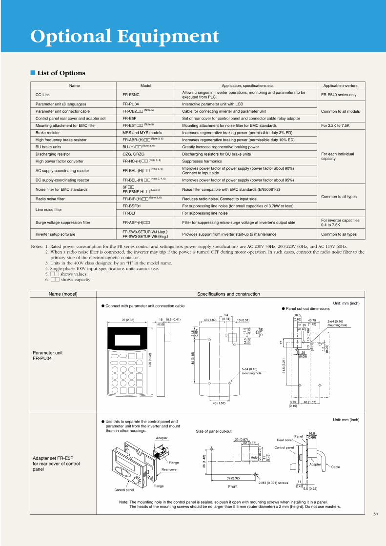
34
List of Options
Optional Equipment
CC-Link FR-E5NCAllows changes in inverter operations, monitoring and parameters to be
FR-E540 series only.executed from PLC.
Parameter unit (8 languages) FR-PU04 Interactive parameter unit with LCD
Parameter unit connector cable FR-CB2 Cable for connecting inverter and parameter unit
Control panel rear cover and adapter set FR-E5P Set of rear cover for control panel and connector cable relay adapter
Mounting attachment for EMC filter FR-E5T Mounting attachment for noise filter for EMC standards For 2.2K to 7.5K
Brake resistor MRS and MYS models Increases regenerative braking power (permissible duty 3% ED)
High frequency brake resistor FR-ABR-(H) Increases regenerative braking power (permissible duty 10% ED)
BU brake units BU-(H) Greatly increase regenerative braking power
Discharging resistor GZG, GRZG Discharging resistors for BU brake units
High power factor converter FR-HC-(H) Suppresses harmonics
AC supply-coordinating reactor FR-BAL-(H)Improves power factor of power supply (power factor about 90%)Connect to input side
DC supply-coordinating reactor FR-BEL-(H) Improves power factor of power supply (power factor about 95%)
Noise filter for EMC standards SF
Noise filter compatible with EMC standards (EN50081-2)FR-E5NF-H
Radio noise filter FR-BIF-(H) Reduces radio noise. Connect to input side Common to all types
Line noise filterFR-BSF01 For suppressing line noise (for small capacities of 3.7kW or less)
FR-BLF For suppressing line noise
Surge voltage suppression filter FR-ASF-(H) Filter for suppressing micro-surge voltage at inverter’s output sideFor inverter capacities0.4 to 7.5K
Inverter setup softwareFR-SW0-SETUP-WJ (Jap.)
Provides support from inverter start-up to maintenance Common to all typesFR-SW0-SETUP-WE (Eng.)
Name Model Application, specifications etc. Applicable inverters
Common to all models
For each individualcapacity
(Note 5)
(Note 5)
(Note 5)
(Note 3, 6)
(Note 3, 6)
(Note 3, 6)
(Note 3, 6)
(Note 3, 6)
(Note 3, 4, 6)
Notes: 1. Rated power consumption for the FR series control and settings box power supply specifications are AC 200V 50Hz, 200/220V 60Hz, and AC 115V 60Hz.2. When a radio noise filter is connected, the inverter may trip if the power is turned OFF during motor operation. In such cases, connect the radio noise filter to the
primary side of the electromagnetic contactor.3. Units in the 400V class designed by an “H” in the model name.4. Single-phase 100V input specifications units cannot use.5. MM shows values.6. MM shows capacity.
Name (model) Specifications and construction
Parameter unitFR-PU04
Connect with parameter unit connection cable
Use this to separate the control panel and parameter unit from the inverter and mount them in other housings.
Panel cut-out dimensions
72 (2.83) 15
(0.59)
10.5 (0.41)
125
(4.9
2)
80 (
3.15
)21
.5(0
.85)
18.5
(0.7
3)14
.5(0
.57)
20(0
.79)
24(0.94)48 (1.89) 13 (0.51)
40 (1.57)
5-ø4 (0.16)mounting hole
16.5(0.65) 43.75
(1.72)
17
1.5
(0.0
6)
1.5
(0.0
6)13(0
.51)
3.75(0.15)
40 (1.57)
11.75(0.46)
1.25(0.05)
81.5
(3.
21)
2-ø4 (0.16)mounting hole
Unit: mm (inch)
Unit: mm (inch)
Adapter set FR-E5P for rear cover of control panel
11(0.43)
16.8(0.66)
5.5 (0.22)
22 (0.87)Adapter
22 (0.87)
20 (
0.79
)11
(0.4
3)
36 (
1.42
)
59 (2.32)
Control panel
Flange
Rear cover
Flange
Size of panel cut-out
Hole
Front
AdapterCable
Rear cover
2-M3 (0.021) screws
Control panel
Panel
Note: The mounting hole in the control panel is sealed, so push it open with mounting screws when installing it in a panel. The heads of the mounting screws should be no larger than 5.5 mm (outer diameter) x 2 mm (height). Do not use washers.
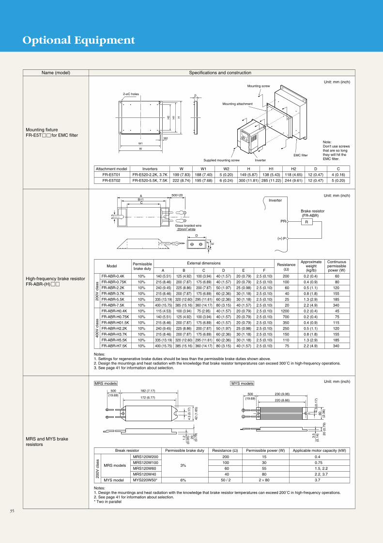
35
Optional Equipment
500(19.69) 500
(19.69)230 (9.06)
220 (8.66)
182 (7.17)
172 (6.77)
4.3
(0.1
7)
42 (
1.65
)
60(2
.36)
20 (
0.79
)
3.5
(0.1
4)4.
3 (0
.17)
20(0
.79)
1.2
(0.0
5)
Brake resistor (FR-ABR)
RPR
(+) P
Inverter
5.3
EF
AB±1
C
500±20
Glass braided wire20mm white2
D
Name (model) Specifications and construction
Mounting fixture FR-E5T for EMC filter
High-frequency brake resistorFR-ABR-(H)
Unit: mm (inch)
Unit: mm (inch)
Model Permissiblebrake duty
External dimensions Resistance(Ω)
Approximateweight(kg/lb)
Continuouspermissiblepower (W)
FR-ABR-0.4K
FR-ABR-0.75K
FR-ABR-2.2K
FR-ABR-3.7K
FR-ABR-5.5K
FR-ABR-7.5K
FR-ABR-H0.4K
FR-ABR-H0.75K
FR-ABR-H01.5K
FR-ABR-H2.2K
FR-ABR-H3.7K
FR-ABR-H5.5K
FR-ABR-H7.5K
Attachment model
FR-E5T01
FR-E5T02
Inverters
FR-E520-2.2K, 3.7K
FR-E520-5.5K, 7.5K
W
199 (7.83)
222 (8.74)
W1
188 (7.40)
195 (7.68)
W2
5 (0.20)
6 (0.24)
H
149 (5.87)
300 (11.81)
H1
138 (5.43)
285 (11.22)
H2
118 (4.65)
244 (9.61)
D
12 (0.47)
12 (0.47)
C
4 (0.16)
5 (0.20)
10%
10%
10%
10%
10%
10%
10%
10%
10%
10%
10%
10%
10%
140 (5.51)
215 (8.46)
240 (9.45)
215 (8.46)
335 (13.19)
400 (15.75)
115 (4.53)
140 (5.51)
215 (8.46)
240 (9.45)
215 (8.46)
335 (13.19)
400 (15.75)
125 (4.92)
200 (7.87)
225 (8.86)
200 (7.87)
320 (12.60)
385 (15.16)
100 (3.94)
125 (4.92)
200 (7.87)
225 (8.86)
200 (7.87)
320 (12.60)
385 (15.16)
100 (3.94)
175 (6.89)
200 (7.87)
175 (6.89)
295 (11.61)
360 (14.17)
75 (2.95)
100 (3.94)
175 (6.89)
200 (7.87)
175 (6.89)
295 (11.61)
360 (14.17)
40 (1.57)
40 (1.57)
50 (1.97)
60 (2.36)
60 (2.36)
80 (3.15)
40 (1.57)
40 (1.57)
40 (1.57)
50 (1.97)
60 (2.36)
60 (2.36)
80 (3.15)
20 (0.79)
20 (0.79)
25 (0.98)
30 (1.18)
30 (1.18)
40 (1.57)
20 (0.79)
20 (0.79)
20 (0.79)
25 (0.98)
30 (1.18)
30 (1.18)
40 (1.57)
2.5 (0.10)
2.5 (0.10)
2.5 (0.10)
2.5 (0.10)
2.5 (0.10)
2.5 (0.10)
2.5 (0.10)
2.5 (0.10)
2.5 (0.10)
2.5 (0.10)
2.5 (0.10)
2.5 (0.10)
2.5 (0.10)
200
100
60
40
25
20
1200
700
350
250
150
110
75
60
80
120
155
185
340
45
75
115
120
155
185
340
0.2 (0.4)
0.4 (0.9)
0.5 (1.1)
0.8 (1.8)
1.3 (2.9)
2.2 (4.9)
0.2 (0.4)
0.2 (0.4)
0.4 (0.9)
0.5 (1.1)
0.8 (1.8)
1.3 (2.9)
2.2 (4.9)
A B C D E F
Notes:1. Settings for regenerative brake duties should be less than the permissible brake duties shown above.2. Design the mountings and heat radiation with the knowledge that brake resistor temperatures can exceed 300˚C in high-frequency operations.3. See page 41 for information about selection.
Mounting screw
Mounting attachment
Supplied mounting screw Inverter
EMC filter
Note: Don't use screws that are so long they will hit the EMC filter.
200V
cla
ss400V
cla
ss
MRS and MYS brake resistors
MYS models Unit: mm (inch)
Resistance (Ω) Applicable motor capacity (kW)Break resistor Permissible brake duty Permissible power (W)
MRS models
MYS model
3%
6%
MRS120W200
MRS120W100
MRS120W60
MRS120W40
MYS220W50*
200
100
60
40
50 / 2
15
30
55
80
2 × 80
0.4
0.75
1.5, 2.2
2.2, 3.7
3.7
Notes:1. Design the mountings and heat radiation with the knowledge that brake resistor temperatures can exceed 200˚C in high-frequency operations.2. See page 41 for information about selection.* Two in parallel
MRS models
200V
cla
ss
W1
W
W2
H2
H1 H
D2-øC holes
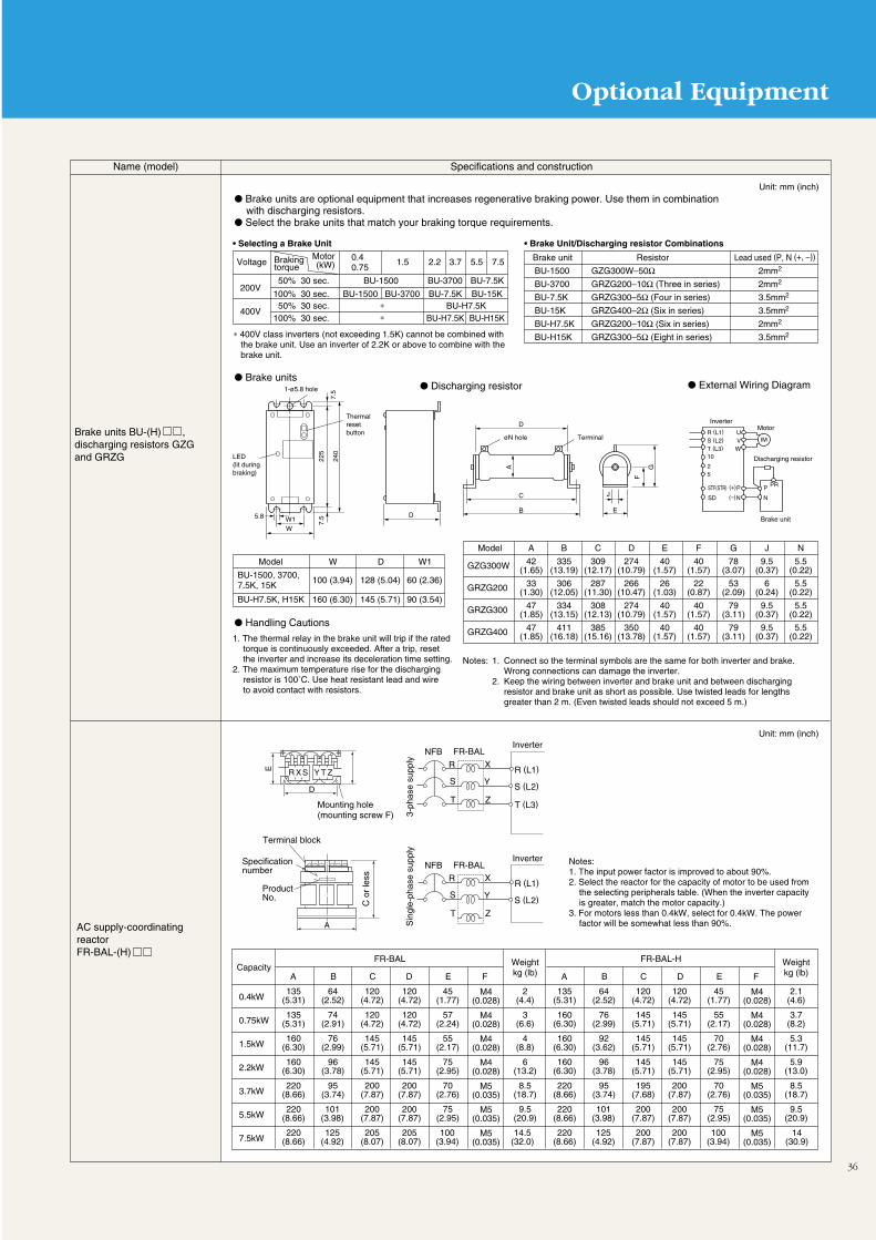
36
Optional Equipment
Name (model) Specifications and construction
Brake units BU-(H) , discharging resistors GZG and GRZG
Unit: mm (inch)
• Selecting a Brake Unit
Brake units are optional equipment that increases regenerative braking power. Use them in combination with discharging resistors.
Select the brake units that match your braking torque requirements.
Brake units
Handling Cautions
Discharging resistor External Wiring Diagram
Voltage 1.5 2.2 3.7Brakingtorque
Motor(kW)
200V
400V
∗ 400V class inverters (not exceeding 1.5K) cannot be combined withthe brake unit. Use an inverter of 2.2K or above to combine with the brake unit.
50% 30 sec. BU-1500 BU-3700
Brake unit
BU-1500
BU-3700
BU-7.5K
BU-15K
BU-H7.5K
BU-H15K
Lead used (P, N (+, –))
2mm2
2mm2
3.5mm2
3.5mm2
2mm2
3.5mm2
Resistor
GZG300W–50ΩGRZG200–10Ω (Three in series)
GRZG300–5Ω (Four in series)
GRZG400–2Ω (Six in series)
GRZG200–10Ω (Six in series)
GRZG300–5Ω (Eight in series)
100% 30 sec. BU-1500 BU-3700 BU-7.5K
5.5 7.5
BU-7.5K
BU-15K50% 30 sec. ∗
∗100% 30 sec. BU-H7.5KBU-H7.5K
BU-H15K
0.40.75
• Brake Unit/Discharging resistor Combinations
Model A
42(1.65)
33(1.30)
47(1.85)
47(1.85)
B
335(13.19)
306(12.05)
334(13.15)
411(16.18)
C
309(12.17)
287(11.30)
308(12.13)
385(15.16)
D
274(10.79)
266(10.47)
274(10.79)
350(13.78)
E
40(1.57)
26(1.03)
40(1.57)
40(1.57)
F
40(1.57)
22(0.87)
40(1.57)
40(1.57)
G
78(3.07)
53(2.09)
79(3.11)
79(3.11)
J
9.5(0.37)
6(0.24)
9.5(0.37)
9.5(0.37)
N
5.5(0.22)
5.5(0.22)
5.5(0.22)
5.5(0.22)
GZG300W
GRZG200
GRZG300
GRZG400
1-ø5.8 hole
LED(lit duringbraking)
Thermal reset button
Model
BU-1500, 3700, 7.5K, 15K
W
100 (3.94)
D
128 (5.04)
W1
60 (2.36)
160 (6.30)BU-H7.5K, H15K 145 (5.71) 90 (3.54)
Notes: 1. Connect so the terminal symbols are the same for both inverter and brake. Wrong connections can damage the inverter.
2. Keep the wiring between inverter and brake unit and between discharging resistor and brake unit as short as possible. Use twisted leads for lengths greater than 2 m. (Even twisted leads should not exceed 5 m.)
AC supply-coordinating reactorFR-BAL-(H)
Unit: mm (inch)
Notes:1. The input power factor is improved to about 90%.2. Select the reactor for the capacity of motor to be used from
the selecting peripherals table. (When the inverter capacity is greater, match the motor capacity.)
3. For motors less than 0.4kW, select for 0.4kW. The power factor will be somewhat less than 90%.
Capacity
0.4kW
0.75kW
1.5kW
2.2kW
3.7kW
5.5kW
7.5kW
FR-BAL Weightkg (lb)B C D E FA
135(5.31)
135(5.31)
160(6.30)
160(6.30)
M4(0.028)
M4(0.028)
M4(0.028)
M4(0.028)
M5(0.035)
M5(0.035)
M5(0.035)
220(8.66)
220(8.66)
220(8.66)
120(4.72)
120(4.72)
145(5.71)
145(5.71)
200(7.87)
200(7.87)
205(8.07)
120(4.72)
120(4.72)
145(5.71)
145(5.71)
200(7.87)
200(7.87)
205(8.07)
45(1.77)
57(2.24)
55(2.17)
75(2.95)
70(2.76)
75(2.95)
100(3.94)
2(4.4)
3(6.6)
4(8.8)
6(13.2)
8.5(18.7)
9.5(20.9)
14.5(32.0)
64(2.52)
74(2.91)
76(2.99)
96(3.78)
95(3.74)
101(3.98)
125(4.92)
FR-BAL-H Weightkg (lb)B C D E FA
135(5.31)
160(6.30)
160(6.30)
160(6.30)
M4(0.028)
M4(0.028)
M4(0.028)
M4(0.028)
M5(0.035)
M5(0.035)
M5(0.035)
220(8.66)
220(8.66)
220(8.66)
120(4.72)
145(5.71)
145(5.71)
145(5.71)
195(7.68)
200(7.87)
200(7.87)
120(4.72)
145(5.71)
145(5.71)
145(5.71)
200(7.87)
200(7.87)
200(7.87)
45(1.77)
55(2.17)
70(2.76)
75(2.95)
70(2.76)
75(2.95)
100(3.94)
2.1(4.6)
3.7(8.2)
5.3(11.7)
5.9(13.0)
8.5(18.7)
9.5(20.9)
14(30.9)
64(2.52)
76(2.99)
92(3.62)
96(3.78)
95(3.74)
101(3.98)
125(4.92)
3-ph
ase
supp
ly
Mounting hole(mounting screw F)
D
E
C o
r le
ss
A
Terminal block
Specification number
Product No.
R X S Y T Z
NFB FR-BAL
R (L1)
S (L2)
T (L3)
R
S
T
X
Y
Z
Inverter
Sin
gle-
phas
e su
pply
NFB FR-BAL
R (L1)
S (L2)
R
S
T
X
Y
Z
Inverter
1. The thermal relay in the brake unit will trip if the rated torque is continuously exceeded. After a trip, reset the inverter and increase its deceleration time setting.
2. The maximum temperature rise for the discharging resistor is 100˚C. Use heat resistant lead and wire to avoid contact with resistors.
PRP
N
(+) P
(–) N
STF(STR)
SD
UVW
R (L1)
S (L2)
T (L3)10
25
IM
W1W
5.8
7.5
7.5
225
240
GA
F
D
C
D
B E
J
øN hole Terminal
InverterMotor
Discharging resistor
Brake unit
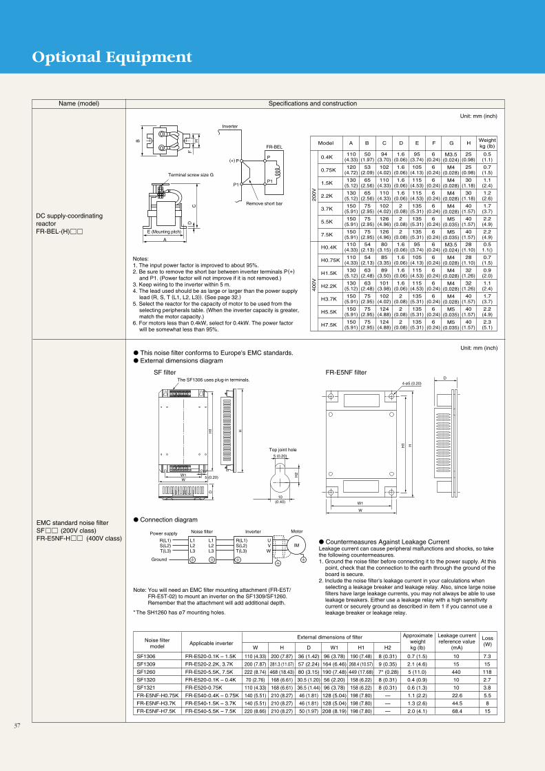
37
Optional Equipment
Name (model) Specifications and construction
Unit: mm (inch)
Countermeasures Against Leakage CurrentLeakage current can cause peripheral malfunctions and shocks, so take the following countermeasures.1. Ground the noise filter before connecting it to the power supply. At this
point, check that the connection to the earth through the ground of the board is secure.
2. Include the noise filter's leakage current in your calculations when selecting a leakage breaker and leakage relay. Also, since large noise filters have large leakage currents, you may not always be able to use leakage breakers. Either use a leakage relay with a high sensitivity current or securely ground as described in item 1 if you cannot use a leakage breaker or leakage relay.
W1
The SF1306 uses plug-in terminals.
W5 (0.20)
5 (0.20)
10(0.40)
D
H2
H1 H
This noise filter conforms to Europe's EMC standards. External dimensions diagram
Connection diagram
SF filter FR-E5NF filter
Top joint hole
Noise filtermodel
Applicable inverterExternal dimensions of filter Approximate
weightkg (lb)
Leakage currentreference value
(mA)
Loss(W)
W
110 (4.33)
200 (7.87)
H
200 (7.87)
281.3 (11.07)
D
36 (1.42)
57 (2.24)
W1
96 (3.78)
164 (6.46)
H1
190 (7.48)
268.4 (10.57)
H2
8 (0.31)
9 (0.35)
0.7 (1.5)
2.1 (4.6)
10
15
7.3
15
FR-E520-0.1K – 1.5K
FR-E520-2.2K, 3.7K
SF1306
SF1309
222 (8.74) 468 (18.43) 80 (3.15) 190 (7.48) 449 (17.68) 7* (0.28) 5 (11.0) 440 118FR-E520-5.5K, 7.5KSF1260
70 (2.76) 168 (6.61) 30.5 (1.20) 56 (2.20) 158 (6.22) 8 (0.31) 0.4 (0.9) 10 2.7FR-E520-0.1K – 0.4KSF1320
110 (4.33) 168 (6.61) 36.5 (1.44) 96 (3.78) 158 (6.22) 8 (0.31) 0.6 (1.3) 10 3.8FR-E520-0.75KSF1321
140 (5.51) 210 (8.27) 46 (1.81) 128 (5.04) 198 (7.80) —FR-E540-0.4K – 0.75KFR-E5NF-H0.75K
140 (5.51) 210 (8.27) 46 (1.81) 128 (5.04) 198 (7.80) —FR-E540-1.5K – 3.7KFR-E5NF-H3.7K
220 (8.66) 210 (8.27) 50 (1.97) 208 (8.19) 198 (7.80)
1.1 (2.2)
1.3 (2.6)
2.0 (4.1)
22.6
44.5
68.4
5.5
8
15—FR-E540-5.5K – 7.5KFR-E5NF-H7.5K
L1L2L3
R(L1)S(L2)T(L3)
L1L2L3
UVW
R(L1)S(L2)T(L3)
Power supply Noise filter Inverter Motor
Ground
Note: You will need an EMC filter mounting attachment (FR-E5T/FR-E5T-02) to mount an inverter on the SF1309/SF1260. Remember that the attachment will add additional depth.
*The SH1260 has ø7 mounting holes.
W1
W
H1 H
4-ø5 (0.20)D
EMC standard noise filterSF (200V class)FR-E5NF-H (400V class)
Unit: mm (inch)
DC supply-coordinating reactorFR-BEL-(H)
Notes:1. The input power factor is improved to about 95%.2. Be sure to remove the short bar between inverter terminals P(+)
and P1. (Power factor will not improve if it is not removed.)3. Keep wiring to the inverter within 5 m.4. The lead used should be as large or larger than the power supply
lead (R, S, T (L1, L2, L3)). (See page 32.)5. Select the reactor for the capacity of motor to be used from the
selecting peripherals table. (When the inverter capacity is greater, match the motor capacity.)
6. For motors less than 0.4kW, select for 0.4kW. The power factor will be somewhat less than 95%.
Weightkg (lb)
Model B C D E FA
0.4K110
(4.33)
0.75K120
(4.72)
1.5K130
(5.12)
2.2K130
(5.12)
3.7K
5.5K
7.5K
M3.5(0.024)
M4(0.028)
M4(0.028)
M4(0.028)
M4(0.028)
M5(0.035)
M5(0.035)
150(5.91)
150(5.91)
150(5.91)
94(3.70)
102(4.02)
110(4.33)
110(4.33)
102(4.02)
126(4.96)
126(4.96)
1.6(0.06)
1.6(0.06)
1.6(0.06)
1.6(0.06)
2(0.08)
2(0.08)
2(0.08)
95(3.74)
105(4.13)
115(4.53)
115(4.53)
135(5.31)
135(5.31)
135(5.31)
G
6(0.24)
6(0.24)
6(0.24)
6(0.24)
6(0.24)
6(0.24)
6(0.24)
H
25(0.98)
25(0.98)
30(1.18)
30(1.18)
40(1.57)
40(1.57)
40(1.57)
0.5(1.1)
0.7(1.5)
1.1(2.4)
1.2(2.6)
1.7(3.7)
2.2(4.9)
2.2(4.9)
50(1.97)
53(2.09)
65(2.56)
65(2.56)
75(2.95)
75(2.95)
75(2.95)
(+) PP
P1P1
FR-BEL
A
E (Mounting pitch)
CHB
DF
Terminal screw size G
Inverter
Remove short bar
200V
H0.4K110
(4.33)
H0.75K110
(4.33)
H1.5K130
(5.12)
H2.2K130
(5.12)
H3.7K
H5.5K
H7.5K
M3.5(0.024)
M4(0.028)
M4(0.028)
M4(0.028)
M4(0.028)
M5(0.035)
M5(0.035)
150(5.91)
150(5.91)
150(5.91)
80(3.15)
85(3.35)
89(3.50)
101(3.98)
102(4.02)
124(4.88)
124(4.88)
1.6(0.06)
1.6(0.06)
1.6(0.06)
1.6(0.06)
2(0.08)
2(0.08)
2(0.08)
95(3.74)
105(4.13)
115(4.53)
115(4.53)
135(5.31)
135(5.31)
135(5.31)
6(0.24)
6(0.24)
6(0.24)
6(0.24)
6(0.24)
6(0.24)
6(0.24)
28(1.10)
28(1.10)
32(1.26)
32(1.26)
40(1.57)
40(1.57)
40(1.57)
0.51.1()
0.7(1.5)
0.9(2.0)
1.1(2.4)
1.7(3.7)
2.2(4.9)
2.3(5.1)
54(2.13)
54(2.13)
63(2.48)
63(2.48)
75(2.95)
75(2.95)
75(2.95)
400V
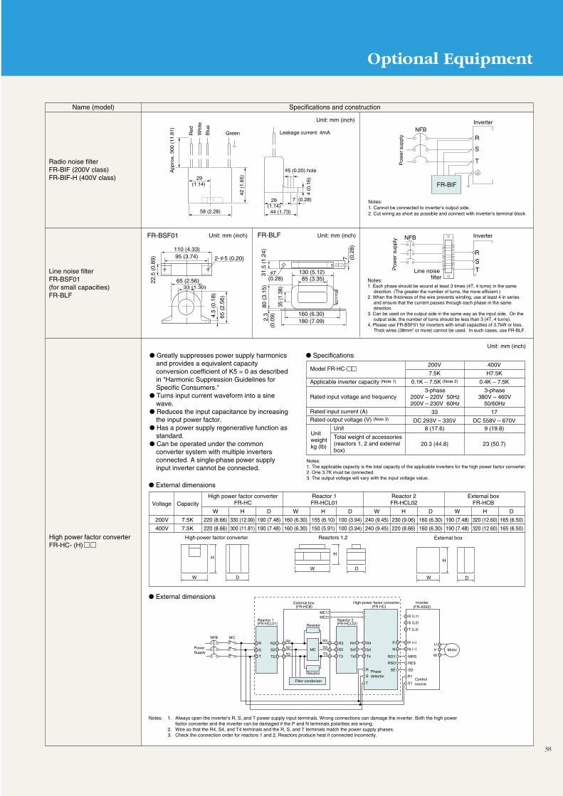
Optional Equipment
38
Name (model) Specifications and construction
High power factor converterFR-HC- (H)
Unit: mm (inch)
Greatly suppresses power supply harmonics and provides a equivalent capacity conversion coefficient of K5 = 0 as described in "Harmonic Suppression Guidelines for Specific Consumers."
Turns input current waveform into a sine wave.
Reduces the input capacitance by increasing the input power factor.
Has a power supply regenerative function as standard.
Can be operated under the common converter system with multiple inverters connected. A single-phase power supply input inverter cannot be connected.
Specifications
External dimensions
External dimensions
Model FR-HC-200V
7.5K
0.1K – 7.5K (Note 2)
3-phase200V – 220V 50Hz200V – 230V 60Hz
33
DC 293V – 335V8 (17.6)
20.3 (44.8)
400V
H7.5K
0.4K – 7.5K
3-phase380V – 460V
50/60Hz
17
DC 558V – 670V9 (19.8)
23 (50.7)
Applicable inverter capacity (Note 1)
Rated input voltage and frequency
Rated input current (A)Rated output voltage (V) (Note 3)
Unit
Total weight of accessories (reactors 1, 2 and externalbox)
Unitweightkg (lb)
Notes:1. The applicable capacity is the total capacity of the applicable inverters for the high power factor converter.2. One 3.7K must be connected.3. The output voltage will vary with the input voltage value.
Notes: 1. Always open the inverter's R, S, and T power supply input terminals. Wrong connections can damage the inverter. Both the high power factor converter and the inverter can be damaged if the P and N terminals polarities are wrong.
2. Wire so that the R4, S4, and T4 terminals and the R, S, and T terminals match the power supply phases.3. Check the connection order for reactors 1 and 2. Reactors produce heat if connected incorrectly.
High power factor converterFR-HC
Reactor 1FR-HCL01Voltage Capacity
Reactor 2FR-HCL02
External boxFR-HCB
200V
400V
7.5K
7.5K
W
220 (8.66)
220 (8.66)
H
330 (12.99)
300 (11.81)
D
190 (7.48)
190 (7.48)
W
160 (6.30)
160 (6.30)
H
155 (6.10)
150 (5.91)
D
100 (3.94)
100 (3.94)
W
240 (9.45)
240 (9.45)
H
230 (9.06)
220 (8.66)
D
160 (6.30)
160 (6.30)
W
190 (7.48)
190 (7.48)
H
320 (12.60)
320 (12.60)
D
165 (6.50)
165 (6.50)
W D
H
DW
H
W
H
D
High-power factor converter Reactors 1,2 External box
PowerSupply
NFB MC
MC
MC1MC2
R
R
R (L1)
R1
S
S
S (L2)
S1
T
T
T (L3)
Reactor 1(FR-HCL01)
R2 R2 R3R3 R4 R4
S2 S2 S3 S3 S4 S4
T2 T2 T3T3 T4 T4
External box(FR-HCB)
Resistor
P
N
P (+)
N (–)
RDY
RSO
SE
MRS
RES
SD
Control source
High-power factor converter(FR-HC)
Inverter(FR-A500)
Motor
U
V
W
Phase detector
Filter condenser
Reactor 2(FR-HCL02)
Resistor
Notes:1. Cannot be connected to inverter's output side.2. Cut wiring as short as possible and connect with inverter's terminal block
Radio noise filter FR-BIF (200V class)FR-BIF-H (400V class)
Line noise filterFR-BSF01 (for small capacities)FR-BLF
Red Leakage current: 4mA
29(1.14)
58 (2.28)
29(1.14)
42 (
1.65
)
7 (0.28)
44 (1.73)
4 (0
.16)
App
rox.
300
(11
.81)
5 (0.20) hole
NFB
FR-BIF
R
S
T
Inverter
Whi
te
Blu
e
Green
Pow
er s
uppl
y
110 (4.33)95 (3.74) 2- 5 (0.20)
22.5
(0.
89)
33 (1.30)
65 (
2.56
)
65 (2.56)
4.5
(0.1
8)
Unit: mm (inch)
Unit: mm (inch) Unit: mm (inch) Inverter
Notes: 1. Each phase should be wound at least 3 times (4T, 4 turns) in the same
direction. (The greater the number of turns, the more efficient.)2. When the thickness of the wire prevents winding, use at least 4 in series
and ensure that the current passes through each phase in the same direction.
3. Can be used on the output side in the same way as the input side. On the output side, the number of turns should be less than 3 (4T, 4 turns).
4. Please use FR-BSF01 for inverters with small capacities of 3.7kW or less. Thick wires (38mm2 or more) cannot be used. In such cases, use FR-BLF.
FR-BLFFR-BSF01
7 (0.28)
130 (5.12)85 (3.35)
160 (6.30)180 (7.09)2.
3(0
.09)
80 (
3.15
)
35 (1
.38)
31.5
(1.
24)
7 (0.2
8)
NFB
Line noise filter
RSTP
ower
sup
ply
39
Characteristic Data
Rotational Speed/Load Torque Characteristics
General-purpose flux vector control (slip compensation selected) V/F control
Rotation speed ( r/min )
300
200
100
0
–100
–200
–300
30 90 180 300 600 900 1200 1500 1800
Load
torq
ue (
%)
300
200
100
0
-100
-200
-300
90 300 900 1500 1800
Rotation speed(r/min)
Load
torq
ue (
%)
Note: The data shown is for an inverter combined with a Mitsubishi 0.75kW 4P motor.
These figures compare rotational speed/load torque characteristics and rotational speed/motor current for general-purpose flux vector controland V/F control. For general-purpose flux vector control, it is clear that 200% or better of torque is output at 6Hz operation.
Example of Motor Noise (A Characteristics with no Load)
Example of Noise Terminal Voltage (Average Values)
80
70
60
50
00 10 20 30 40 50 60
Noi
se le
vel
(dB
)
PWM carrier frequency 14.5kHz
Commercial rotation speed
Operating frequency (Hz)
120
100
80
60
40
20
00.1 1 10 100
Noi
se te
rmin
al v
olta
ge (
dB)
Carrier frequency (10kHz)
Carrier frequency (1kHz)
Noise frequency (MHz)
40
Application of Special Motors
Motor Applications
Motors with BrakesUse a motor with a brake that has an independent power supply forthe brake, connect the brake supply to the primary supply of theinverter, use the output stop terminal (MRS) for braking (stoppingthe motor), and turn the inverter output off. Depending on the typeof brake, there may be a clattering noise in the brake lining at lowspeeds. This is not a malfunction.
Motors with a Variable Numbers of PolesWhen the number of motor poles is convertible, the rated currentwill differ from a standard motor, so check the motor's maximumcurrent when selecting an inverter. Be sure to stop the motor beforeswitching the number of poles. Switching on the fly will engage theregenerative overvoltage protection circuit, trigger the inverteralarm, and send the motor into a coasting stop.
Geared MotorsThe ranges for continuous operation vary with both the lubricationsystem used and the manufacturer. Oil lubricated motors areparticularly prone to burning of gears when operated exclusively atlow speeds. Consult the manufacturer before operating motors atspeeds in excess of 60Hz.
Synchronous MotorsApplications that involve load fluctuations and high impacts caneasily put a motor out of synchronization, so these are not suitableapplications. They have higher starting currents and rated currentsthan standard motors and do not maintain stable speeds at lowspeeds, please take these factors into consideration.
Single-Phase MotorsSingle-phase motors are not suited to variable speed operation withinverters. The harmonic current that flows to the capacitor incapacitor-started motors can damage the capacitor. Motors that arephase-split started or repulsion started not only do not provideoutput torque at low speeds, their internal centrifugal force switchesalso do not engage, so their starting coils sometimes burn. If inverteroperation is desired please use three-phase motors.
Wiring The inverter will be damaged if electric power is applied to the
inverter's output terminals U, V, and W. Before switching on thepower, please check the wiring and sequence very carefully.
Terminals P (+), PR, P1, and N (–) are designed for use inconnecting dedicated optional equipment. Do not connect otherequipment to these terminals. Also, do not short frequencysetting power supply terminal 10 to common terminal 5.
Installation Please install the unit in a clean location, avoiding adverse
environments such as oil mist, lint, dust etc. or use it within asealed enclosure which keeps out floating particles. Theenclosure's cooling system and dimensions should allow theinverter's ambient temperature to remain within the permissiblevalues (see page 9 for specifications).
Since certain parts of the inverter can get extremely hot, do notattach it to combustible material.
The unit should be installed vertically.
Settings Control panel settings make it possible to set the inverter for high
speed operations up to 400Hz, so a mistake when setting can bevery dangerous. Use the maximum frequency setting function toset an upper limit. (The default setting is a maximum frequencyof 60 Hz during external input signal operations. PU operation isset for 120Hz.)
Please do not set the regenerative brake duty function (Pr.70)except when the optional brake resistor is being used. Since thisfunction is used to protect against brake resistor overheating, donot set it beyond the brake resistor's permissible duty.
Setting the DC braking voltage and operation time at a highervalue than the default setting can cause motor overheating(electronic thermal trip).
Power Requirements If the unit is installed close to a large-capacity power supply
transformer, or where switching of a phase advance capacitoroccurs, an excessive peak current may flow in the power inputcircuit, damaging the inverter. In such cases, be sure to install anoptional FR-BEL or FR-BAL power supply coordinating reactor.
If a surge voltage occurs in the power system, the surge energy
may flow into the inverter, causing the inverter to display E.OV1,E.OV2, or E.OV3 and execute an alarm stop. In such cases, besure to install an optional FR-BEL or FR-BAL power supplycoordinating reactor.
Operation To avoid damage to the inverter when a magnetic contactor (MC)
is installed on the primary side, please do not subject the MC torepeated start/stop operations.
When a malfunction occurs in the inverter, the protectionfunction engages to halt inverter output but does not suddenlystop the motor itself. For this reason, please install themechanical stopping and holding mechanism necessary foremergency stops.
When the inverter's power supply is cut off, it takes time for thecapacitors to discharge. When carrying out inspections, wait atleast ten minutes after the power cuts off, then use a meter toconfirm that the voltage has decreased.
Operating Cautions
0
500
1000
1500
Length of wiring (m)10
Power SupplyEquipment
Capacity (kVA)
Range for power factor improvement reactor installation

Cautions
41
For Maximum Safety
In order to use the equipment properly and safely, be sure toread the manual before use.
Mitsubishi general-purpose inverters are not designed ormanufactured to be used in equipment or systems in situationsthat can affect or endanger human life.
When considering this equipment for operation in specialapplications such as machinery or systems used in passengertransportation, medical, aerospace, atomic power, electricpower, or submarine repeating applications, please contact yournearest Mitsubishi sales representative.
Although this product was manufactured under conditions ofstrict quality control, you are strongly advised to install safetydevices to forestall serious accidents when it is used in facilitieswhere a breakdown in the product is likely to cause a seriousaccident.
Please do not use for loads other than 3-phase induction motors.
Selection Cautions
Selecting Inverter Capacity When running special motors or several motors in parallel off a
single inverter, select an inverter capacity so that the total motorrated current (at 50Hz) is lower than the inverter's rated outputcurrent.
To make the motor quieter, set the PWM carrier frequency (Pr.72)to 2kHz or higher and lower the output current as described inthe rating table on page 8 if you are using it in an ambientenvironment of 40˚C or more. (Also change the setting forelectronic thermal O/L relay, Pr.9.) If the temperature is lowerthan 40˚C, however, there is no need to lower the output current.Note that when the PWM carrier frequency is raised, the motorgets quieter but the inverter produces more noise and leakagecurrent. Select Soft-PWM control with (Pr.240) to hold down theincrease in noise and make it less irritating.
Selecting a Brake Resistor Use the following table to select a brake resistor based on its
braking torque and permissible duty (%ED).
For Selecting Peripherals
Selecting and Installing No-Fuse Breakers Please install a no-fuse breaker (NFB) on the incoming side to
protect the wiring on the inverter's primary side. The selection ofthe NFB depends on the power factor on the inverter's powersupply side (changes in supply voltage, output frequency, orload) (See page 32). In particular, since the operatingcharacteristics of fully electromagnetic NFBs are altered byharmonic currents, it is necessary to select larger capacities.(Refer to the documentation for the appropriate breakers formore information.) Use Mitsubishi's anti-harmonic and anti-surgeProgressive Super Series as leakage breakers. (See page 32.)
If you are installing no-fuse breakers on the secondary side of theinverter, ripple currents will generate heat at the contacts, soselect a higher capacity.
Handling of Primary Magnetic Contactors When operating through the external terminals (using terminals
STF or STR), install a magnetic contactor (MC) on the primaryside to prevent accidents caused by restarts when the powercomes on after it has been off and ensure safety in maintenancework. Do not use the MC to engage in frequent starts and stops.(The life of the inverter input circuit is about 100,000 on-offs.)
When operating the parameter unit, you cannot start operationwith an MC since the device does not restart automatically afterpower is restored. It is generally not a good idea to stop with theprimary MC. The inverter's special regenerative brake will notwork, so the result will be a coasting stop.
Handling of Secondary Magnetic Contactors You should generally not install a magnetic contactor between
the inverter and the motor and turn the inverter on and off duringoperation. If the inverter is turned on during operation, a largein-rush current flows into the inverter, and the inverter may stoprunning due to the overcurrent. If an MC is used to switch to thecommercial power supply, the MC must be switched from ON toOFF (inverter circuit) or from OFF to ON (commercial powercircuit) only after the inverter and the motor have stopped.
Acceleration and Deceleration Times The motor's acceleration/deceleration time is determined by the
torque and load torque generated by the motor and by themoment of inertia (GD2) of the load.
Should the current limit function or stall prevention functionengage during acceleration/deceleration, the time sometimesincreases, so make the acceleration/deceleration time greater.
To shorten the acceleration/deceleration time, make the torqueboost value larger, select general-purpose flux vector control orincrease inverter and motor capacity. (Too large a torque boostvalue will activate the stall prevention function, actuallylengthening the acceleration time.) To shorten the decelerationtime, add the optional MRS or FR-ABR brake resistor (for 0.4K orhigher).
Motor Starting Torque The starting and accelerating characteristics of motors driven by
inverters are constrained by the overload current rating of theinverters used. Torque characteristic values are smaller thanwhen general commercial power supplies are used. When alarger starting torque is necessary, select general-purpose fluxvector control (set motor capacity using Pr.80) or adjust thetorque boost value. When even these measures are inadequate,choose an inverter with a capacity one rank higher or increasethe capacity of both the motor and the inverter.
CapacityPermissible duty 3%ED Permissible duty 10%ED
100% torque 150% torque 100% torque 150% torque
0.1K – – – –
0.2K – – – –
0.4K MRS120W200 FR-ABR-0.4K
0.75K MRS120W100 FR-ABR-0.75K
1.5K MRS120W60 FR-ABR-2.2K
2.2K MRS120W60 MRS120W40 FR-ABR-2.2K FR-ABR-3.7K
3.7K MRS120W40 MYS220W50 FR-ABR-3.7K FR-ABR-5.5K(two in parallel)
5.5K – – FR-ABR-5.5K –
7.5K – – FR-ABR-7.5K –
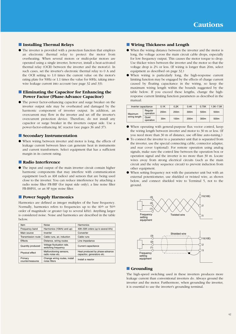
42
Installing Thermal Relays The inverter is provided with a protection function that employs
an electronic thermal relay to protect the motor fromoverheating. When several motors or multi-polar motors areoperated using a single inverter, however, install a heat-activatedthermal relay (OCR) between the inverter and the motor(s). Insuch cases, set the inverter's electronic thermal relay to 0 A andthe OCR setting to 1.0 times the current value on the motor'srating plate for 50Hz or 1.1 times the value for 60Hz, taking inter-wire leakage current into account (see page 32 and 33).
Eliminating the Capacitor for Enhancing thePower Factor (Phase-Advance Capacitor)
The power factor-enhancing capacitor and surge breaker on theinverter output side may be overheated and damaged by theharmonic component of inverter output. In addition, anovercurrent may flow in the inverter and set off the inverter'sovercurrent protection device. Therefore, do not install anycapacitor or surge breaker in the inverters output side. Use apower-factor-enhancing AC reactor (see pages 36 and 37).
Secondary Instrumentation When wiring between inverter and motor is long, the effects of
leakage current between lines can generate heat in instrumentsand current transformers. Select equipment that has a sufficientmargin in its current rating.
Radio Interference The input and output of the main inverter circuit contain higher
harmonic components that may interfere with communicationequipment (such as AM radios) and sensors that are being usedclose to the inverter. You can reduce interference by attaching aradio noise filter FR-BIF (for input side only), a line noise filterFR-BSF01, or an SF type noise filter.
Power Supply HarmonicsHarmonics are defined as integer multiples of the base frequency.Normally, harmonics refers to frequencies up to the 40 th or 50 th
order of magnitude or greater (up to several kHz). Anything largeris considered noise. Noise and harmonics are described in the tablebelow.
Wiring Thickness and Length When the wiring distance between the inverter and the motor is
long, the voltage across the main circuit cable drops, especiallyfor low frequency output. This causes the motor torque to drop.Use thicker wires between the inverter and the motor so that thevoltage drop is 2% or less. (If wiring is longer than 20m, selectequipment as described on page 32.)
When wiring is particularly long, the high-response currentlimiting function may be engaged by the effects of charge currentcaused by floating capacitance in the wiring, so keep themaximum wiring length within the bounds suggested by thetable below. If you exceed these lengths, change the high-response current limiting function parameters as described in themanual.
GroundingThe high-speed switching used in these inverters produces moreleakage current than conventional inverters do. Always ground theinverter and the motor. Furthermore, when grounding the inverter,it is essential to use the inverter's grounding terminal.
When operating with general-purpose flux vector control, keepthe wiring length between inverter and motor to 30 m or less. (Ifyou need more than 30 m of distance, use off-line auto-tuning.)
To connect the inverter to a parameter unit that is separated fromthe inverter, use the special connecting cable, connector adapter,and rear cover (optional). For remote operation using analogsignals, make sure the control line between the operation box oroperation signal and the inverter is no more than 30 m. Locatewires away from strong electrical circuits (such as the maincircuit and the relay sequence circuit) to prevent induction fromother equipment.
When setting frequency not with the parameter unit but with anexternal potentiometer, use shielded or twisted wire, as shownbelow, and connect shielded wire to Terminal 5, not to theground.
Item Noise Harmonics
Frequency band Harmonics (10kHz and up) 40th–50th orders (up to several kHz)
Main source Inverter Converter
Transmission route Cable runs, air, induction Cable runs
Effects Distance, wiring routes Line impedance
Quantity produced Voltage fluctuation rate, Current capacitanceswitching frequency
Physical effect Malfunctioning sensors, Heat produced by phase-advanceradio noise etc. capacitor, generators etc.
Primary Change wiring routes, install Install a reactorcountermeasures noise filters
Frequency setting equipment
10(10E)
2
5
10(10E)
2
5
Twisted wire
Shielded wire
(1)
(2)
(3)
(1)
(2)
(3)
Frequency setting equipment
Inverter capacitance 0.1K 0.2K 0.4K 0.75K 1.5K–7.5K
Regular200m 200m 300m 500m 500m
Maximum operationwiring length Quiet
30m 100m 200m 300m 500moperation
Cautions

L-174-9-C3984-B NA9904 Printed in Japan (BUN)
Revised publication, effective Apr. 1999Superseding publication L-174-8-C3984-A Aug. 1998
Specifications subject to change without notice.
Safety WarningTo ensure proper use of the products listed in this catalog,please be sure to read the instruction manual prior to use.
Related Documents

![Compaq Armada E500 V300[1]](https://static.cupdf.com/doc/110x72/577d1f4e1a28ab4e1e90511a/compaq-armada-e500-v3001.jpg)