RESEARCH AND EDUCATION Flexural strength of small connector designs of zirconia-based partial fixed dental prostheses Tamer A. Hamza, BDS, MS, PhD, a Mazen A. Attia, BDS, MS, PhD, b Mohamed Mahmoud Khalil El-Hossary, BDS, MS, PhD, c Ihab E. Mosleh, BDS, MS, PhD, d Tamer E. Shokry, BDS, MS, PhD, e and Alvin G. Wee, BDS, DDS, MS, MPH, PhD f Dental patients increasingly demand esthetic restorations; however, the inherent weak- ness of ceramic restorations is considered a significant limi- tation. 1 The introduction of yttria-stabilized tetragonal zir- conia polycrystalline (Y-TZP)- based restoration is considered a breakthrough in the dental field because of the excellent tissue tolerance, esthetics, and transformation toughening property, which give a high flexure strength (up to 1200 MPa) and fracture toughness (6-9 MPa$m ½ ) compared with other ceramic systems. 2-5 However, in spite of the high mechanical properties of Y-TZP-based restorations, clinical failures still occur, usually at the connector area of fixed dental prostheses (FDPs). 6 Clinical recommen- dations for Y-TZP-based FDP connectors varied from 2 to 4 mm in height and width. 7-12 In a Associate Professor, Crown and Fixed Prosthodontics Department, Faculty of Dental Medicine, Al-Azhar University, Cairo, Egypt. b Lecturer, Crown and Fixed Prosthodontics Department, Faculty of Oral and Dental Medicine, Beni Suef University, Cairo, Egypt. c Professor, Crown and Fixed Prosthodontics Department, Faculty of Dental Medicine, Al-Azhar University, Cairo, Egypt. d Professor, Fixed Prosthodontics, Faculty of Dentistry, King Abdulaziz University, Jeddah, Saudi Arabia. e Associate Professor, Crown and Fixed Prosthodontics Department, Faculty of Dental Medicine, Al-Azhar University, Cairo, Egypt. f Section Head, Maxillofacial Prosthodontics, Veterans Affairs Nebraska Western Iowa Health Care System, Omaha, Neb.; and Special Professor, Department of Prosthodontics, Creighton University School of Dentistry, Omaha, Neb. ABSTRACT Statement of problem. Partial fixed dental prostheses with a small connector size are required for optimal esthetics and limited interarch space; however, final strength is endangered. Purpose. The purpose of this in vitro study was to evaluate the effect of different connector designs on the flexural strength of simulated 3-unit partial fixed dental prostheses made of yttria- stabilized tetragonal zirconia polycrystalline using computer-aided design and computer-aided manufacturing technology. Material and methods. To simulate a 3-unit partial fixed dental prosthesis, 20 rectangular bar- shaped specimens were fabricated with dimensions of 4 ±0.05 mm (H)×4 ±0.05 mm (W)×30 0.5 mm (L). Each bar specimen had 2 constricted parts on both sides, representing the connector and defining a central pontic of 10 ±0.10 mm in length. The specimens were divided into 4 groups according to the connector diameter and design, as follows: SR: 2 mm (H)×3 mm (W) round 0.6 mm radius of curvature; SS: 2 mm (H)×3 mm (W) sharp 0.1 mm radius of curvature; CR: 3 mm (H)×3 mm (W) round 0.6 mm radius of curvature; and CS: 3 mm (H)×3 mm (W) sharp 0.1 mm radius of curvature. An additional 5 specimens were fabricated with no constriction and served as the control group. The specimens were subjected to a 3-point flexural strength test in a universal testing machine with a crosshead speed of 0.5 mm/min until failure. Scanning electron microscopic and photomicrograph images were used to examine the fracture surfaces. Two-way ANOVA and the Tukey-Kramer post hoc test were used to analyze the data (a=.05). Results. The mean flexural strength for SR 2 mm (H)×3 mm (W) round 0.6 mm radius of curvature (583.6 ±49.7 MPa) was significantly higher than that of SS, which was 2 mm (H)×3 mm (W) sharp 0.1 mm radius of curvature (502.8 ±23.3 MPa). Similarly, the mean flexural strength for CR was 3 mm (H)×3 mm (W) round 0.6 mm radius of curvature (682.9 ±36.8), which was significantly higher than that of CC, 3 mm (H)×3 mm (W) sharp 0.1 mm radius of curvature (486.7 ±35.6 MPa). Conclusions. The flexural strength of the yttria-stabilized tetragonal zirconia polycrystalline-based ceramics was affected by the connector dimension and design. The 2-round connector design was more able to withstand occlusal forces than the sharp design. The 3-connector design with a minimum cross section of 2×3 mm is recommended for anterior fixed dental prostheses, provided it has a round curvature. (J Prosthet Dent 2016;115:224-229) 224 THE JOURNAL OF PROSTHETIC DENTISTRY

Welcome message from author
This document is posted to help you gain knowledge. Please leave a comment to let me know what you think about it! Share it to your friends and learn new things together.
Transcript
RESEARCH AND EDUCATION
aAssociate PrbLecturer, CrcProfessor, CdProfessor, FeAssociate PrfSection HeaProsthodontic
224
Flexural strength of small connector designs of zirconia-basedpartial fixed dental prostheses
Tamer A. Hamza, BDS, MS, PhD,a Mazen A. Attia, BDS, MS, PhD,b
Mohamed Mahmoud Khalil El-Hossary, BDS, MS, PhD,c Ihab E. Mosleh, BDS, MS, PhD,d
Tamer E. Shokry, BDS, MS, PhD,e and Alvin G. Wee, BDS, DDS, MS, MPH, PhDf
ABSTRACTStatement of problem. Partial fixed dental prostheses with a small connector size are required foroptimal esthetics and limited interarch space; however, final strength is endangered.
Purpose. The purpose of this in vitro study was to evaluate the effect of different connectordesigns on the flexural strength of simulated 3-unit partial fixed dental prostheses made of yttria-stabilized tetragonal zirconia polycrystalline using computer-aided design and computer-aidedmanufacturing technology.
Material and methods. To simulate a 3-unit partial fixed dental prosthesis, 20 rectangular bar-shaped specimens were fabricated with dimensions of 4 ±0.05 mm (H)×4 ±0.05 mm (W)×30 0.5mm (L). Each bar specimen had 2 constricted parts on both sides, representing the connectorand defining a central pontic of 10 ±0.10 mm in length. The specimens were divided into 4groups according to the connector diameter and design, as follows: SR: 2 mm (H)×3 mm (W)round 0.6 mm radius of curvature; SS: 2 mm (H)×3 mm (W) sharp 0.1 mm radius of curvature;CR: 3 mm (H)×3 mm (W) round 0.6 mm radius of curvature; and CS: 3 mm (H)×3 mm (W) sharp0.1 mm radius of curvature. An additional 5 specimens were fabricated with no constriction andserved as the control group. The specimens were subjected to a 3-point flexural strength test ina universal testing machine with a crosshead speed of 0.5 mm/min until failure. Scanningelectron microscopic and photomicrograph images were used to examine the fracture surfaces.Two-way ANOVA and the Tukey-Kramer post hoc test were used to analyze the data (a=.05).
Results. The mean flexural strength for SR 2 mm (H)×3 mm (W) round 0.6 mm radius of curvature(583.6 ±49.7 MPa) was significantly higher than that of SS, which was 2 mm (H)×3 mm (W) sharp 0.1mm radius of curvature (502.8 ±23.3 MPa). Similarly, the mean flexural strength for CR was 3 mm(H)×3 mm (W) round 0.6 mm radius of curvature (682.9 ±36.8), which was significantly higher thanthat of CC, 3 mm (H)×3 mm (W) sharp 0.1 mm radius of curvature (486.7 ±35.6 MPa).
Conclusions. The flexural strength of the yttria-stabilized tetragonal zirconia polycrystalline-basedceramics was affected by the connector dimension and design. The 2-round connector design wasmore able to withstand occlusal forces than the sharp design. The 3-connector design with aminimum cross section of 2×3 mm is recommended for anterior fixed dental prostheses,provided it has a round curvature. (J Prosthet Dent 2016;115:224-229)
Dental patients increasinglydemand esthetic restorations;however, the inherent weak-ness of ceramic restorations isconsidered a significant limi-tation.1 The introduction ofyttria-stabilized tetragonal zir-conia polycrystalline (Y-TZP)-based restoration is considereda breakthrough in the dentalfield because of the excellenttissue tolerance, esthetics, andtransformation tougheningproperty, which give a highflexure strength (up to 1200MPa) and fracture toughness(6-9 MPa$m½) compared withother ceramic systems.2-5
However, in spite of thehigh mechanical properties ofY-TZP-based restorations,clinical failures still occur,usually at the connector areaof fixed dental prostheses(FDPs).6 Clinical recommen-dations for Y-TZP-based FDPconnectors varied from 2 to 4mm in height and width.7-12 In
ofessor, Crown and Fixed Prosthodontics Department, Faculty of Dental Medicine, Al-Azhar University, Cairo, Egypt.own and Fixed Prosthodontics Department, Faculty of Oral and Dental Medicine, Beni Suef University, Cairo, Egypt.rown and Fixed Prosthodontics Department, Faculty of Dental Medicine, Al-Azhar University, Cairo, Egypt.ixed Prosthodontics, Faculty of Dentistry, King Abdulaziz University, Jeddah, Saudi Arabia.ofessor, Crown and Fixed Prosthodontics Department, Faculty of Dental Medicine, Al-Azhar University, Cairo, Egypt.d, Maxillofacial Prosthodontics, Veterans Affairs Nebraska Western Iowa Health Care System, Omaha, Neb.; and Special Professor, Department ofs, Creighton University School of Dentistry, Omaha, Neb.
THE JOURNAL OF PROSTHETIC DENTISTRY
Clinical ImplicationsThe fabrication of partial fixed dental prostheseswith a minimum connector size requires the useof a round connector design to improve flexuralstrength.
February 2016 225
a survey of the literature, Larsson et al7 compared thefracture strength of 4 unit Y-TZP-based FDP withdifferent connector size (2.0, 2.5, 3.0, 3.5, and 4.0 mm)and concluded that the minimum recommended diam-eter is 4 mm. Schmitter et al11 stated that the use of Y-TZP-based FDPs with a 9 mm2 connector was clinicallyrecommended. Oh and Anusavice12 concluded that thefracture strength of ceramic restorations is influenced bythe radius of the gingival curvature of the pontic, wherethe failure load increased with the increase of the radiusat the gingival embrasure. Similarly, Plengsombut et al13
stated that fracture usually occurs in the gingival surfaceof the connector and propagates toward the pontic.Kamposiora et al,14 in their 2-dimensional finite elementstress analysis method, also showed that increasing theconnector height dramatically reduces the stress levelswithin the connectors. Y-TZP-based restorations can befabricated by copy milling or computer-aided design andcomputer-aided manufacturing (CAD/CAM) technology.Wimmer et al15 found that FDPs fabricated from CAD/CAM resin withstand higher load values than thoseconventionally fabricated.
In the fabrication of FDPs, properly designed con-nectors allow the separation of the units, thus permittingthe development of natural-appearing labial embrasures.The smaller connector size can allow technicians toachieve this goal. Although this affects overall strength,7
determining the minimum dimensions for the connectorthat can be used clinically is useful. A metal ceramicrestoration allows the use of a small connector size, sothe esthetic goal can be achieved from this perspective.16
However, with ceramic restorations, different studieshave evaluated connector size and shape and addressedthe minimum size needed to fabricate a clinicallyacceptable ceramic restoration. Results have provencontroversial.17-24
The purpose of this in vitro study was to evaluate theeffect of different connector designs on the flexuralstrength of simulated 3-unit zirconia FDPs using CAD/CAM technology. The null hypothesis was that theflexural strength of Y-TZP-based FDPs would not beaffected by altering the connector size or geometry.
MATERIAL AND METHODS
A power analysis of the flexural strength data wasdesigned to determine an adequate sample size by Epi
Hamza et al
Info v6 (US Centers for Disease Control and Prevention)to calculate the sample size, guided by the power of thetest, 80%, and the accepted margin of error, 5%. Thealpha level was .05, b .20 for the power of 80%. The effectsize calculation was based on the study of Plengsombutet al,13 which found a statistically significant differenceequal to 386.2 N between Zir-CAD (IPS e.max Zir CAD)and Press (IPS e.max Press). The predicted number was 5specimens in each group.
To simulate a 3-unit FDP, 20 rectangular bar-shapedspecimens, of the same design used by Plengsombutet al,13 with dimensions of 4 ±0.05 mm (H)×4 ±0.05 mm(W)×30 ±0.5 mm (L), were made. Each bar specimen had2 constricted parts on both sides representing theconnector and defining a central pontic of 10 ±0.10 mmin length (Fig. 1). An additional 5 specimens fabricatedwith no constriction served as the control group.
The specimens were divided in 4 groups according tothe connector diameter and design, as follows: smallround connector (SR): 2 mm (H)×3 mm (W) round 0.6mm radius of curvature; small sharp connector (SS): 2mm (H)×3 mm (W) sharp 0.1 mm radius of curvature;conventional round connector (CR): 3 mm (H)×3 mm(W) round 0.6 mm radius of curvature; and conventionalsharp connector (CS): 3 mm (H)×3 mm (W) sharp 0.1mm radius of curvature.
To fabricate the specimens, partially sintered zirconiablocks (41×84 mm) (Procera zirconia; Nobel Biocare)were attached to a 5-axis water-cooled CAD/CAM mill-ing machine (CAD/CAM machine 3011; Nobel Biocare).The system software created a 3-dimensional model of abar-shaped specimen (4×4×30 mm), and the machinewas activated to mill the required design. Each millingblock produced 5 specimens. After initial milling, the 4connector designs previously described were machined atboth ends of each bar at a 10 mm distance. The design ofeach connector was added to the software module andthe milling tool number 12 and 13 (Diamond disc cutter110; Nobel Biocare), then changed to meet the design ofthe required connectors. After milling, the specimenswere detached from the mounting frame and polished ona metallographic rotating device (M3000; Buehler Ltd)with ascending grit silicon carbide paper (600, 800, 1000)to remove milling trace lines. The specimens were thensintered according to the manufacturer’s instructions(1500�C for 6 hours) in a furnace (Procera Lava; NobelBiocare). The dimensions of the produced specimenswere measured and verified with an electronic caliperwith an accuracy of 0.01 mm.
All sintered specimens were then subjected to 3-pointflexure strength test using a universal testing machine(model LRX-plus; Lloyd Instruments Ltd). The speci-mens were vertically loaded by means of a steel ball witha diameter of 3 mm at a crosshead speed of 0.5 mm perminute placed in the center of the pontic. The span of the
THE JOURNAL OF PROSTHETIC DENTISTRY
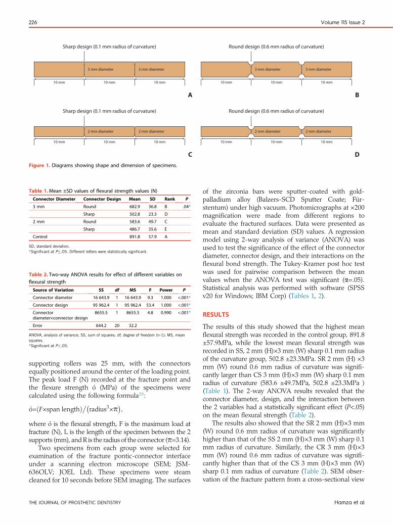
Table 1.Mean ±SD values of flexural strength values (N)
Connector Diameter Connector Design Mean SD Rank P
3 mm Round 682.9 36.8 B .04*
Sharp 502.8 23.3 D
2 mm Round 583.6 49.7 C
Sharp 486.7 35.6 E
Control 891.8 57.9 A
SD, standard deviation.*Significant at P�.05. Different letters were statistically significant.
3 mm diameter
Sharp design (0.1 mm radius of curvature) Round design (0.6 mm radius of curvature)
Sharp design (0.1 mm radius of curvature) Round design (0.6 mm radius of curvature)
10 mm 10 mm 10 mm
3 mm diameter
2 mm diameter
10 mm 10 mm 10 mm
2 mm diameter
3 mm diameter
10 mm 10 mm 10 mm
3 mm diameter
2 mm diameter
10 mm 10 mm 10 mm
2 mm diameter
A B
C DFigure 1. Diagrams showing shape and dimension of specimens.
Table 2. Two-way ANOVA results for effect of different variables onflexural strength
Source of Variation SS df MS F Power P
Connector diameter 16 643.9 1 16 643.9 9.3 1.000 <.001*
Connector design 95 962.4 1 95 962.4 53.4 1.000 <.001*
Connectordiameter×connector design
8655.5 1 8655.5 4.8 0.990 <.001*
Error 644.2 20 32.2
ANOVA, analysis of variance; SS, sum of squares; df, degree of freedom (n-1); MS, meansquares.*Significant at P�.05.
226 Volume 115 Issue 2
supporting rollers was 25 mm, with the connectorsequally positioned around the center of the loading point.The peak load F (N) recorded at the fracture point andthe flexure strength ó (MPa) of the specimens werecalculated using the following formula25:
�o=ðF×span lengthÞ��radius3×p�;
where ó is the flexural strength, F is the maximum load atfracture (N), L is the length of the specimen between the 2supports (mm), andR is the radius of the connector (p=3.14).
Two specimens from each group were selected forexamination of the fracture pontic-connector interfaceunder a scanning electron microscope (SEM; JSM-636OLV; JOEL Ltd). These specimens were steamcleaned for 10 seconds before SEM imaging. The surfaces
THE JOURNAL OF PROSTHETIC DENTISTRY
of the zirconia bars were sputter-coated with gold-palladium alloy (Balzers-SCD Sputter Coate; Für-stentum) under high vacuum. Photomicrographs at ×200magnification were made from different regions toevaluate the fractured surfaces. Data were presented asmean and standard deviation (SD) values. A regressionmodel using 2-way analysis of variance (ANOVA) wasused to test the significance of the effect of the connectordiameter, connector design, and their interactions on theflexural bond strength. The Tukey-Kramer post hoc testwas used for pairwise comparison between the meanvalues when the ANOVA test was significant (a=.05).Statistical analysis was performed with software (SPSSv20 for Windows; IBM Corp) (Tables 1, 2).
RESULTS
The results of this study showed that the highest meanflexural strength was recorded in the control group, 891.8±57.9MPa, while the lowest mean flexural strength wasrecorded in SS, 2 mm (H)×3 mm (W) sharp 0.1 mm radiusof the curvature group, 502.8 ±23.3MPa. SR 2 mm (H) ×3mm (W) round 0.6 mm radius of curvature was signifi-cantly larger than CS 3 mm (H)×3 mm (W) sharp 0.1 mmradius of curvature (583.6 ±49.7MPa, 502.8 ±23.3MPa )(Table 1). The 2-way ANOVA results revealed that theconnector diameter, design, and the interaction betweenthe 2 variables had a statistically significant effect (P<.05)on the mean flexural strength (Table 2).
The results also showed that the SR 2 mm (H)×3 mm(W) round 0.6 mm radius of curvature was significantlyhigher than that of the SS 2 mm (H)×3 mm (W) sharp 0.1mm radius of curvature. Similarly, the CR 3 mm (H)×3mm (W) round 0.6 mm radius of curvature was signifi-cantly higher than that of the CS 3 mm (H)×3 mm (W)sharp 0.1 mm radius of curvature (Table 2). SEM obser-vation of the fracture pattern from a cross-sectional view
Hamza et al
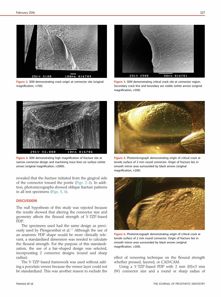
Figure 2. SEM demonstrating crack origin at connector site (originalmagnification, ×100).
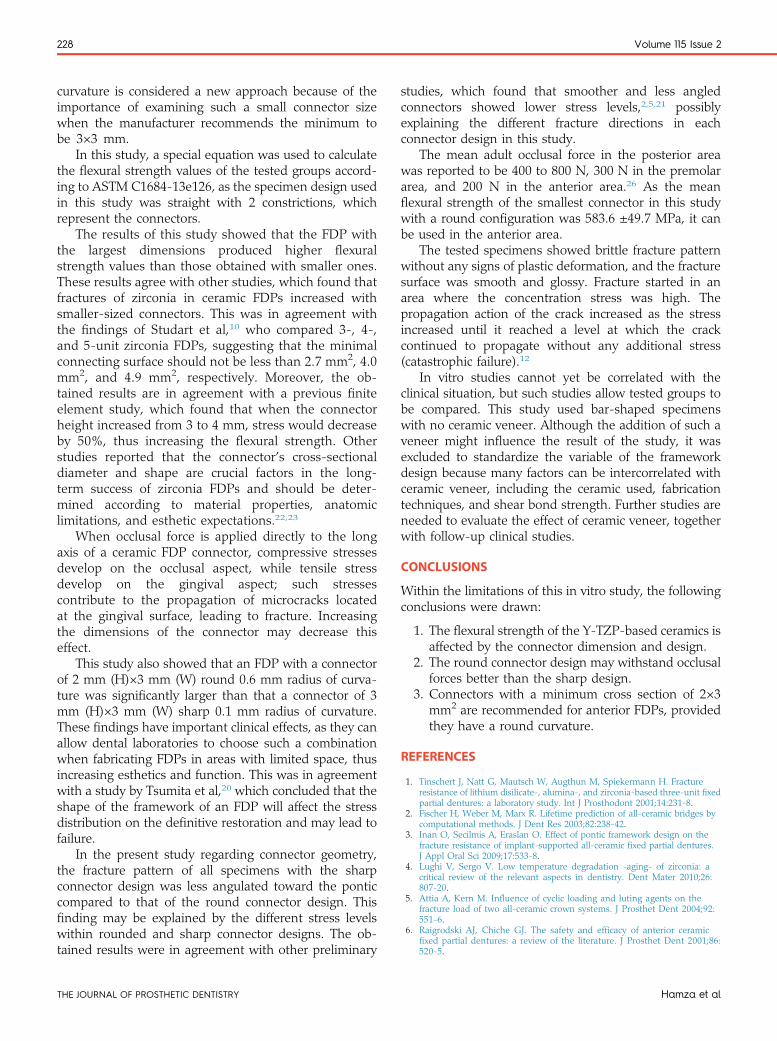
Figure 3. SEM demonstrating critical crack site at connector region.Secondary crack line and boundary are visible (white arrow) (originalmagnification, ×500).
Figure 4. SEM demonstrating high magnification of fracture site atnarrow connector design and machining trace lines on surface (whitearrow) (original magnification, ×2000).
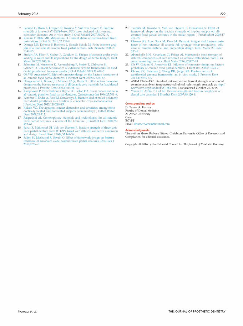
Figure 5. Photomicrograph demonstrating origin of critical crack attensile surface of 3 mm round connector. Origin of fracture lies insmooth mirror area surrounded by black arrows (originalmagnification, ×200).
Figure 6. Photomicrograph demonstrating origin of critical crack attensile surface of 2 mm round connector. Origin of fracture lies insmooth mirror area surrounded by black arrows (originalmagnification, ×200).
February 2016 227
revealed that the fracture initiated from the gingival sideof the connector toward the pontic (Figs. 2-4). In addi-tion, photomicrographs showed oblique fracture patternsin all test specimens (Figs. 5, 6).
DISCUSSION
The null hypothesis of this study was rejected becausethe results showed that altering the connector size andgeometry affects the flexural strength of Y-TZP-basedFDP.
The specimens used had the same design as previ-ously used by Plengsombut et al.13 Although the use ofan anatomic FDP shape would be more clinically rele-vant, a standardized dimension was needed to calculatethe flexural strength. For the purpose of this standardi-zation, the use of a bar-shaped design was selected,incorporating 2 connector designs (round and sharpradius).
The Y-TZP-based framework was used without add-ing a porcelain veneer because the veneer layer could notbe standardized. This was another reason to exclude the
Hamza et al
effect of veneering technique on the flexural strengthwhether pressed, layered, or CAD/CAM.
Using a Y-TZP-based FDP with 2 mm (H)×3 mm(W) connector size and a round or sharp radius of
THE JOURNAL OF PROSTHETIC DENTISTRY
228 Volume 115 Issue 2
curvature is considered a new approach because of theimportance of examining such a small connector sizewhen the manufacturer recommends the minimum tobe 3×3 mm.
In this study, a special equation was used to calculatethe flexural strength values of the tested groups accord-ing to ASTM C1684-13e126, as the specimen design usedin this study was straight with 2 constrictions, whichrepresent the connectors.
The results of this study showed that the FDP withthe largest dimensions produced higher flexuralstrength values than those obtained with smaller ones.These results agree with other studies, which found thatfractures of zirconia in ceramic FDPs increased withsmaller-sized connectors. This was in agreement withthe findings of Studart et al,10 who compared 3-, 4-,and 5-unit zirconia FDPs, suggesting that the minimalconnecting surface should not be less than 2.7 mm2, 4.0mm2, and 4.9 mm2, respectively. Moreover, the ob-tained results are in agreement with a previous finiteelement study, which found that when the connectorheight increased from 3 to 4 mm, stress would decreaseby 50%, thus increasing the flexural strength. Otherstudies reported that the connector’s cross-sectionaldiameter and shape are crucial factors in the long-term success of zirconia FDPs and should be deter-mined according to material properties, anatomiclimitations, and esthetic expectations.22,23
When occlusal force is applied directly to the longaxis of a ceramic FDP connector, compressive stressesdevelop on the occlusal aspect, while tensile stressdevelop on the gingival aspect; such stressescontribute to the propagation of microcracks locatedat the gingival surface, leading to fracture. Increasingthe dimensions of the connector may decrease thiseffect.
This study also showed that an FDP with a connectorof 2 mm (H)×3 mm (W) round 0.6 mm radius of curva-ture was significantly larger than that a connector of 3mm (H)×3 mm (W) sharp 0.1 mm radius of curvature.These findings have important clinical effects, as they canallow dental laboratories to choose such a combinationwhen fabricating FDPs in areas with limited space, thusincreasing esthetics and function. This was in agreementwith a study by Tsumita et al,20 which concluded that theshape of the framework of an FDP will affect the stressdistribution on the definitive restoration and may lead tofailure.
In the present study regarding connector geometry,the fracture pattern of all specimens with the sharpconnector design was less angulated toward the ponticcompared to that of the round connector design. Thisfinding may be explained by the different stress levelswithin rounded and sharp connector designs. The ob-tained results were in agreement with other preliminary
THE JOURNAL OF PROSTHETIC DENTISTRY
studies, which found that smoother and less angledconnectors showed lower stress levels,2,5,21 possiblyexplaining the different fracture directions in eachconnector design in this study.
The mean adult occlusal force in the posterior areawas reported to be 400 to 800 N, 300 N in the premolararea, and 200 N in the anterior area.26 As the meanflexural strength of the smallest connector in this studywith a round configuration was 583.6 ±49.7 MPa, it canbe used in the anterior area.
The tested specimens showed brittle fracture patternwithout any signs of plastic deformation, and the fracturesurface was smooth and glossy. Fracture started in anarea where the concentration stress was high. Thepropagation action of the crack increased as the stressincreased until it reached a level at which the crackcontinued to propagate without any additional stress(catastrophic failure).12
In vitro studies cannot yet be correlated with theclinical situation, but such studies allow tested groups tobe compared. This study used bar-shaped specimenswith no ceramic veneer. Although the addition of such aveneer might influence the result of the study, it wasexcluded to standardize the variable of the frameworkdesign because many factors can be intercorrelated withceramic veneer, including the ceramic used, fabricationtechniques, and shear bond strength. Further studies areneeded to evaluate the effect of ceramic veneer, togetherwith follow-up clinical studies.
CONCLUSIONS
Within the limitations of this in vitro study, the followingconclusions were drawn:
1. The flexural strength of the Y-TZP-based ceramics isaffected by the connector dimension and design.
2. The round connector design may withstand occlusalforces better than the sharp design.
3. Connectors with a minimum cross section of 2×3mm2 are recommended for anterior FDPs, providedthey have a round curvature.
REFERENCES
1. Tinschert J, Natt G, Mautsch W, Augthun M, Spiekermann H. Fractureresistance of lithium disilicate-, alumina-, and zirconia-based three-unit fixedpartial dentures: a laboratory study. Int J Prosthodont 2001;14:231-8.
2. Fischer H, Weber M, Marx R. Lifetime prediction of all-ceramic bridges bycomputational methods. J Dent Res 2003;82:238-42.
3. Inan O, Secilmis A, Eraslan O. Effect of pontic framework design on thefracture resistance of implant-supported all-ceramic fixed partial dentures.J Appl Oral Sci 2009;17:533-8.
4. Lughi V, Sergo V. Low temperature degradation -aging- of zirconia: acritical review of the relevant aspects in dentistry. Dent Mater 2010;26:807-20.
5. Attia A, Kern M. Influence of cyclic loading and luting agents on thefracture load of two all-ceramic crown systems. J Prosthet Dent 2004;92:551-6.
6. Raigrodski AJ, Chiche GJ. The safety and efficacy of anterior ceramicfixed partial dentures: a review of the literature. J Prosthet Dent 2001;86:520-5.
Hamza et al
February 2016 229
7. Larsson C, Holm L, Lovgren N, Kokubo Y, Vult von Steyern P. Fracturestrength of four-unit (Y-TZP)-based FPD cores designed with varyingconnector diameter. An in-vitro study. J Oral Rehabil 2007;34:702-9.
8. Komine F, Blatz MB, Matsumura H. Current status of zirconia-based fixedrestorations. J Oral Sci 2010;52:531-9.
9. Dittmer MP, Kohorst P, Borchers L, Stiesch-Scholz M. Finite element anal-ysis of a four-unit all-ceramic fixed partial denture. Acta Biomater 2009;5:1349-55.
10. Studart AR, Filser F, Kocher P, Gauckler LJ. Fatigue of zirconia under cyclicloading in water and its implications for the design of dental bridges. DentMater 2007;23:106-14.
11. Schmitter M, Mussotter K, Rammelsberg P, Stober T, Ohlmann B,Gabbert O. Clinical performance of extended zirconia frameworks for fixeddental prostheses: two-year results. J Oral Rehabil 2009;36:610-5.
12. Oh WS, Anusavice KJ. Effect of connector design on the fracture resistance ofall-ceramic fixed partial dentures. J Prosthet Dent 2002;87:536-42.
13. Plengsombut K, Brewer JD, Monaco EA Jr, Davis EL. Effect of two connectordesigns on the fracture resistance of all-ceramic core materials for fixed dentalprostheses. J Prosthet Dent 2009;101:166-73.
14. Kamposiora P, Papavasiliou G, Bayne SC, Felton DA. Stress concentration inall-ceramic posterior fixed partial dentures. Quintessence Int 1996;27:701-6.
15. Wimmer T, Ender A, Roos M, Stawarczyk B. Fracture load of milled polymericfixed dental prostheses as a function of connector cross-sectional areas.J Prosthet Dent 2013;110:288-95.
16. Kokich VG. The apparent contact dimension and covariates among ortho-dontically treated and nontreated subjects. [commentary]. J Esthet RestorDent 2009;21:112.
17. Raigrodski AJ. Contemporary materials and technologies for all-ceramicfixed partial dentures: a review of the literature. J Prosthet Dent 2004;92:557-62.
18. Bahat Z, Mahmood DJ, Vult von Steyern P. Fracture strength of three-unitfixed partial denture cores (Y-TZP)-based with different connector dimensionand design. Swed Dent J 2009;33:149-59.
19. Salimi H, Mosharraf R, Savabi O. Effect of framework design on fractureresistance of zirconium oxide posterior fixed partial dentures. Dent Res J2012;9:764-9.
Hamza et al
20. Tsumita M, Kokubo Y, Vult von Steyern P, Fukushima S. Effect offramework shape on the fracture strength of implant-supported all-ceramic fixed partial dentures in the molar region. J Prosthodont 2008;17:274-85.
21. Clausen JO, Abou Tara M, Kern M. Dynamic fatigue and fracture resis-tance of non-retentive all-ceramic full-coverage molar restorations. influ-ence of ceramic material and preparation design. Dent Mater 2010;26:533-8.
22. Aboushelib MN, Kleverlaan CJ, Feilzer AJ. Microtensile bond strength ofdifferent components of core veneered all-ceramic restorations. Part II: zir-conia veneering ceramics. Dent Mater 2006;22:857-63.
23. Oh W, Gotzen N, Anusavice KJ. Influence of connector design on fractureprobability of ceramic fixed-partial dentures. J Dent Res 2002;81:623-7.
24. Chong KK, Palamara J, Wong RH, Judge RB. Fracture force ofcantilevered zirconia frameworks: an in vitro study. J Prosthet Dent2014;112:849-56.
25. ASTM C1684-13e1 Standard test method for flexural strength of advancedceramics at ambient temperature-cylindrical rod strength. Available at: http://www.astm.org/Standards/C1684.htm. Last accessed October 26, 2015.
26. Yilmaz H, Aydin C, Gul BE. Flexural strength and fracture toughness ofdental core ceramics. J Prosthet Dent 2007;98:120-8.
Corresponding author:Dr Tamer A. HamzaFaculty of Dental MedicineAl-Azhar UniversityCairoEGYPTEmail: [email protected]
AcknowledgmentsThe authors thank Barbara Bittner, Creighton University Office of Research andCompliance, for editorial assistance.
Copyright © 2016 by the Editorial Council for The Journal of Prosthetic Dentistry.
THE JOURNAL OF PROSTHETIC DENTISTRY
Related Documents