Flexural Strength of Prestressed Concrete Members Brian C. Skogman Structural Engineer Black & Veatch Kansas City, Missouri Maher K. Tadros Professor of Civil Engineering University of Nebraska Omaha, Nebraska Ronald Grasmick Structural Engineer Dana Larson Roubal and Associates Omaha, Nebraska T he flexural strength theory of prestressed concrete members is well established. The assumptions of equivalent rectangular stress block and plane sections remaining plane after loading are commonly accepted. How- ever, the flexural strength analysis of prestressed concrete sections is more complicated than for sections reinforced with mild bars because high strength prestressing steel does not exhibit a yield stress plateau, and thus cannot be modeled as an elasto-plastic material. In 1979, Mattock' presented a pro- cedure for calculating the flexural strength of prestressed concrete sections on an HP-67/97 programmable cal- culator. His procedure consisted of the theoretically exact "strain compatibil- ity" method and a power formula for modeling the stress-strain curve of prestressing steel. This power formula was originally reported in Ref. 2 and is capable of modeling actual stress-strain curves for all types of steel to within 1 percent. Prior to Mattock's paper, the strain compatibility method commonly re- quired designers to use a graphical so- lution for the steel stress at a given strain. There are computer programs for strain compatibility analysis (see for example Refs. 3 and 4). However, these programs were developed on main 96

Welcome message from author
This document is posted to help you gain knowledge. Please leave a comment to let me know what you think about it! Share it to your friends and learn new things together.
Transcript
Flexural Strength ofPrestressed Concrete
Members
Brian C. SkogmanStructural EngineerBlack & VeatchKansas City, Missouri
Maher K. TadrosProfessor of Civil EngineeringUniversity of NebraskaOmaha, Nebraska
Ronald GrasmickStructural EngineerDana Larson Roubal and
AssociatesOmaha, Nebraska
T he flexural strength theory ofprestressed concrete members is
well established. The assumptions ofequivalent rectangular stress block andplane sections remaining plane afterloading are commonly accepted. How-ever, the flexural strength analysis ofprestressed concrete sections is morecomplicated than for sections reinforcedwith mild bars because high strengthprestressing steel does not exhibit ayield stress plateau, and thus cannot bemodeled as an elasto-plastic material.
In 1979, Mattock' presented a pro-cedure for calculating the flexuralstrength of prestressed concrete sectionson an HP-67/97 programmable cal-
culator. His procedure consisted of thetheoretically exact "strain compatibil-ity" method and a power formula formodeling the stress-strain curve ofprestressing steel. This power formulawas originally reported in Ref. 2 and iscapable of modeling actual stress-straincurves for all types of steel to within 1percent.
Prior to Mattock's paper, the straincompatibility method commonly re-quired designers to use a graphical so-lution for the steel stress at a givenstrain. There are computer programs forstrain compatibility analysis (see forexample Refs. 3 and 4). However, theseprograms were developed on main
96

frame computers for research purposes,and are not intended as design aids.
In this paper, the iterative strain com-patibility method is coded into a userfriendly program in BASIC. The pro-gram assumes a neutral axis depth, cal-culates the corresponding steel strains,and obtains the steel stresses by use ofthe power formula. 2 Force equilibrium(T = C) is checked, and if the differenceis significant, the neutral axis depth isadjusted and the procedure repeateduntil T and C are equal. Users are al-lowed to input steel stress-strain dia-grams with either minimum ASTM spe-cified properties or actual ex-perimentally obtained properties.Noncomposite and composite sectionscan be analyzed, and a library of com-mon precast concrete section shapes isincluded.
A recent survey by the authors is re-ported herein. It indicates that the ac-tual steel stress, at a given strain, couldbe as high as 12 percent over that of min-imum ASTM values. Also, futuredevelopments might produce steeltypes with more favorable propertiesthan those currently covered by ASTMstandards. With sufficient documenta-tion, precast concrete producers coulduse the proposed computer analysis totake advantage of these improved prop-erties.
A second objective of this paper is topresent an approximate noniterativeprocedure for calculating theprestressed steel stress, f, at ultimateflexure, without a computer. The pro-posed procedure requires a hand heldcalculator with the power function y'.Currently, such scientific calculators areinexpensive, which makes the proposedprocedure a logical upgrade of the ap-proximate procedure represented byEq. (18-3) in the ACI 318-83 Code.'
The proposed approximate procedureis essentially a one-cycle strain-com-patibility solution. The main approxi-mation involves initially setting the ten-sile steel stresses equal to the respective
SynopsisFlexural strength theory is reviewed
and a computer program for flexuralanalysis by the iterative strain com-patibility method is presented. It isavailable from the PCI for IBM PC/XTand AT microcomputers and compat-ibles.
Secondly, a new noniterative ap-proximate method for hand calculationof the stress f P5 in prestressed ten-dons at ultimate flexure is presented.It is applicable to composite andnoncomposite sections of any shapewith any number of steel layers, andany type of ASTM steel at any level ofeffective prestress.
Parametric and comparativestudies indicate the proposed methodis more accurate and more powerfulthan other approximate methods.Numerical examples are provided andproposed ACI 318-83 Code andCommentary revisions are given.
yield points of the steel types used inthe cross section, and setting the com-pressive steel stress equal to zero. Ap-proximate steel strains are then com-puted from conditions of equilibriumand compatibility. The final steelstresses are obtained by substituting thestrains into the power formula. How-ever, the main advantage of this proce-dure over current approximate methodsis its applicability to all section shapes,all effective prestress levels, and anycombination of steel types in a givencross section.
The proposed approximate procedureis compared with the precise straincompatibility method and two other ap-proximate procedures: the ACI Codemethod, which was developed for theCode committee by Mattock, 6 and themethod recently proposed by Harajli
PCI JOURNAL/September-October 1988 97

A's —
dps dns
Aps
A ns L
Ens.
(a) Cross Section
CCU 0.85f'c
C Asfsc a =arc CE O.BSf'cba
E s, dec
e s
ZeroStrain Apsfns}T
ps, decAnsf s
ns, dec
(b) Strains (c) Forces
Fig. 1. Flexural strength relationships.
and Naaman. 7 Plots of behavior of thesefour methods under various combina-tions of concrete strength and rein-forcement parameters are discussed.Qualitative comparison with a recentlyintroduced approximate method byLoov is also given. Results indicate thatthe proposed procedure is more accu-rate than the other approximatemethods, and it makes better use of theactual material properties.
Numerical examples are provided toillustrate the proposed procedure and tocompare it with the other approximatemethods. A proposal for revision of theACI Code and Commentary 8 is given inAppendix B.
PROBLEM STATEMENTAND BASIC THEORY
Referring to Fig. 1, the problem maybe stated as follows. Given are thecross-sectional dimensions; the pre-stressed, nonprestressed, and compres-sion steel areas, A ps, A 3 , and A.;, re-spectively; the depths to these areas,dps , d18 , and d', respectively; the con-crete strength f,' and ultimate strain E;
and the stress-strain relationship(s) cf
the steel. The nominal flexural strength,M, is required.
A procedure for obtaining the stress inprestressed and nonprestressed tendonsat ultimate flexure can be developed asfollows. Referring to Fig. 1(c), forceequilibrium (T = C) may be satisfied by;
A9J53 + A ' ./1,., – A Bf; = 0.85f, 1) /3, c (1)
where fp3 , f„8 , and fs are the prestressed,nonprestressed, and compression steelstresses at ultimate flexure, respec-tively; b is the width of the compressionface; f3, is a coefficient defining thedepth of the equivalent rectangularstress block, a, in Section 10.2.7 of ACI318-83; and c is the distance from theextreme compression fiber to the neutralaxis.
If the compression zone is nonrectan-gular or if it consists of different con-crete strengths, Eq. (1) may be rewrittenas follows:
A,J.. + A nafns – A ;f; = Fc (la)
where F, is the total compressive forcein the concrete.
The equivalent rectangular stressdistribution has been shown to be validfor nonrectangular sections, 9 ' 10 so the
98

area of concrete in compression may bedetermined by a consideration of thesection geometry and setting the stressin each type of concrete equal to its re-spective 0.85 f,' value.
Assuming that plane cross sectionsbefore loading remain plane after load-ing, and that perfect bond exists be-tween steel and concrete, an equationcan be written for the strain in steel, Fig.1(b):
di (2)
E i = Ecu ^ — 1 ^- E t. decc
where "i" represents a steel layer des-ignation. A steel layer is defined as agroup of bars or tendons with the samestress-strain properties (type), the sameeffective prestress, and that can be as-sumed to have a combined area with asingle centroid.
In Eq. (2), E i,dee is the strain in steellayer "i" at concrete decompression.The decompression strain, Ei.dec is afunction of the initial prestress and thetime-dependent properties of the con-crete and steel. In lieu of a more accu-rate calculation," the change in steelstrain due to change in concrete stressfrom effective value to zero (i.e., due toconcrete decompression) may be ig-nored. Thus, E i,dec may be computed asfollows. If the effective prestress f,, isknown:
}_8e 3Ei
( ).dec — Ei
or if the effective prestress is unknown:
fPi – 25,000 (4)
Ei.dec = Ei
whereE i = modulus of elasticity of steel
layer "i", psi= initial stress in the tendon before
losses, psiNote that fm is equal to zero for non-
prestressed tendons. The constant25,000 psi (172.4 MPa) approximates the
prestress losses due to creep and shrink-age plus allowance for elastic rebounddue to decompression of the cross sec-tion.
If the value of c from Eq. (1) is sub-stituted into Eq. (2), then Eq. (2) be-comes:
0.85 f, b /3, dil— i.decE i Ecu {' — 1)+
psfps + Anal ns — '^ sf a
(5)
With the strain E i given, the stress maybe determined from an assumed stress-strain relationship, such as the one pre-sented in the following section.
STEEL STRESS -STRAINRELATIONSHIP
In 1979, Mattock' used a power equa-tion 2 to closely represent thestress-strain curve of reinforcing steel(high strength tendons or mild bars).The general form of the power equationis:
fi = E i E LQ + (l + E {R)i Rj —f- (6)
where
EE (7)E * _{ Kfpv
andf i = stress in steel corresponding to a
strain Ei= specified tensile strength of pre-
stressing steeland E, K, Q, and R are constants for anygiven stress-strain curve. In lieu of ac-tual stress-strain curves, values of E, K,Q, and R for the steel type of steel layer"i" may be taken from Table 1, which isbased on minimum ASTM standardproperties.
The values of E, K, Q, and R in Table1 were determined by noting that theyield point (€,,,,, f,,,) and the ultimatestrength point (E Pu , fpn) must satisfy Eq.(6), where E P,,, fp,, and fp„ are the
PCI JOURNAL/September-October 1988 99

Table 1. Tendon steel stress-strain constants for Eq. (6).
f pu(ksi) f py / f pu E (psi) K Q R
0.90 28,000,000 1.04 0.0151 8.449270
strand0.85 28,000,000 1.04 0.0270 6.598
0.90 28,000,000 1.04 0.0137 6.430250
strand0.85 28,000,000 1.04 0.0246 5.305
0.90 29,000,000 1.03 0.0150 6.351250wire
0.85 29,000,000 1.03 0.0253 5.256
0.90 29,000,000 1.03 0.0139 5.463235wire
0.85 29,000,000 1.03 0.0235 4.612
0.85 29,000,000 1.01 0.0161 4.991150bar
0.80 29,000,000 1.01 0.0217 4.224
Note: I ksi = 1000 psi = 6,895 MPa.
Qisbasedonep0=0.05.
minimum ASTM standard values for thesteel type used. A value of e pu = 0.05 wasused for all prestressing steel types,rather than the ASTM specifiedminimum ultimate strain of 0.035 or0.04. This is a conservative assumptionbased on experimental results; its adop-tion results in lower stress values at in-termediate strains.
Other assumptions were necessary tosolve for the constants E, K, Q, and R.These assumptions were made on thebasis of experience gained from theshape of experimental stress-straincurves reported in Refs. 1 and 12, and ina separate section of this paper.
STRAIN COMPATIBILITYAPPROACH AND
COMPUTER PROGRAMThe strain compatibility method usu-
ally requires an iterative numerical so-lution because of the interrelation of the
unknown parameters. A step-by-stepapplication 3.13 of this method is de-scribed as follows:
Step 1: Assume a compression blockdepth, a, and compute the neutral axisdepth, c.
Step 2: Substitute c into Eq. (2) to ob-tain the strain for each steel layer in thesection.
Step 3: Estimate the stress in eachsteel layer by use of a graphical oranalytical stress-strain relationship.
Step 4: Check satisfaction of theequilibrium formula, Eq. (1a).
Step 5: If Eq. (1a) is not satisfied, re-peat Steps 1 through 4 with a new valueof a.
Step 6: When compatibility, Eq. (2),and equilibrium, Eq. (la), are achievedsimultaneously, determine the flexuralstrength, M.
The aforementioned steps were usedto develop a user-friendly flexuralstrength analysis program." The pro-gram can analyze noncomposite and
11
B3
B34 4
Z 2 T3
T5
T6
SAMPLE PRECAST SECTION SHAPES
TOPPING SHAPES
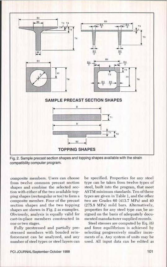
Fig. 2. Sample precast section shapes and topping shapes available with the straincompatibility computer program.
composite members. Users can choosefrom twelve common precast sectionshapes and combine the selected sec-tion with either of the two available top-ping shapes (rectangular or tee) to form acomposite member. Four of the precastsection shapes and the two toppingshapes are shown in Fig. 2 as examples.Obviously, analysis is equally valid forcast-in-place members constructed inone or two stages.
Fully prestressed and partially pre-stressed members with bonded rein-forcement can be analyzed, and anynumber of steel types or steel layers can
be specified. Properties for any steeltype can be taken from twelve types ofsteel, built into the program, that meetASTM minimum standards. Ten of thesetypes are given in Table 1, and the othertwo are Grades 60 (413.7 MPa) and 40(275.8 MPa) mild bars. Alternatively,properties for any steel type can , be as-signed on the basis of adequately docu-mented manufacturer supplied records.
Steel stresses are computed by Eq. (6)and force equilibrium is achieved byselecting progressively smaller incre-ments of a. Any system of units may beused. All input data can be edited as
PCI JOURNAL/September-October 1988 101

many times as needed. This allows use ofthe program for either analysis or design.
The program package is availablefrom the PCI for a nominal charge. Thepackage includes a 5.25 in. (133 mm)diskette, and a manual containing in-strtictions, section shapes, and exampleswith input/output printout.
Actual Versus Assumed SteelStress-Strain Curves
In researching their paper, the authorssolicited stress-strain curves from ten-don suppliers and manufacturers. Se-venty curves were received and theirbreakdown is as follows: 19 curves ofGrade 270 ksi (1862 MPa) stress-re-lieved strand, 23 curves of Grade 270 ksilow-relaxation strand, 13 curves ofGrade 250 ksi (1724 MPa) low-relaxationstrand, and 15 miscellaneous curvesconsisting of stress-relieved or low-re-laxation wire of varying strengths and0.7 in. (17.8 mm) diameter ASTM A779
Table 2. Manufacturer legend forstress-strain curves in Figs. 3, 4 and 5.
CURVE MANUFACTURER/SUPPLIER
A ARMCO INC.BC, BU * FLORIDA WIRE AND CABLE CO.
C PRESTRESS SUPPLY INC.D SHINKO WIRE AMERICA INC.E SIDERIUS INC.F SPRINGFIELD INDUSTRIES CORP.G SUMIDEN WIRE PRODUCTS CORP.
Curve BL represents a lower bound of 10 curves and curveBU represents an upper bound of the same 10 curves.
prestressing strand.Six curves for Grade 270 ksi stress-re-
lieved strand, six curves for Grade 270ksi low-relaxation strand, and twocurves for Grade 250 ksi low-relaxationstrand were considered representativeof the data received. These curves arereproduced in Figs. 3, 4, and 5, respec-tively, and a manufacturer legend isgiven in Table 2. Differences in the
290
G280
270
_--PCI HANDBOOK EQ.260
,-'C
WLu 250 ,'^
cn
240 /CEO. (6) FITTED TO ASTMSPECIFICATIONS WITH K=1.04
I230
2200 .01 .02 .03 .04 .05 .06 .07 .08 .09
STRAIN (in./in.)
Fig. 3. Manufacturer stress-strain curves for ASTM A416, 270 ksi, 7-wire,stress-relieved strand.
102

300l BU*
290 B L'`
280
FrQ.
–'^-E
0)s_ 270
-pCI HANDBOOK EQ.w 260
TED TO ASTM250 IONS WITH K=1.04
240
2300 .01 .02 .03 .04 .05 .06 .07 .08 .09
STRAIN (in./in.)
Fig. 4. Manufacturer stress-strain curves for ASTM A416, 270 ksi, 7-wire,low-relaxation strand.
280C
270
E
260
250
r,(6Fcn-PCI HANDBOOK EQ.
W 240F-TO ASTM
230 WITH K=1.04
220
210 .01 .02 .03 .04 .05 .06 .07 .08 .09
STRAIN (in. /in. )
Fig. 5. Manufacturer stress-strain curves for ASTM A416, 250 ksi, 7-wire,low-relaxation strand.
PCI JOURNAUSeptember-October 1988 103

shape of the curves beyond the yieldstrain, E py=0.01, are attributable to anabsence of data for Curves A, C, D, E,and G for strains greater than 0.015 andless than the ultimate strain, E vu , and forCurves BL and BU for strains greaterthan 0.035 and less than Epu.
The figures also show plots of the PCIDesign Handbook 15 equations and Eq.(6) set to ASTM minimum specifica-tions. For convenience, the PCI DesignHandbook equations are reproducedhere.
If Eps < 0.008 then f,,, = 28,000 E, (ksi)
If E,,> 0.008:For 250 ksi (1724 MPa) strand:
0.058fP3 = 248 – < 0.98 f^ (ksi)Eps – 0.006
(9)
For 270 ksi (1862 MPa) strand:
fps = 268 – 0.075<0.98f (ksi)
E p3 – 0.0065
(10)
The figures show that the minimumASTM curves are very conservative.The PCI Design Handbook equationsplot closer to the actual curves; how-ever, they are slightly unconservative intwo cases in Fig. 5.
Eq. (6) was used to model each man-ufacturer curve in Figs. 3, 4, and 5. Thepercent deviation between each man-ufacturer curve and its correspondingEq. (6) version was computed for E = 0to E ms . The maximum percent deviationfor each type of strand for E > 0 and E
0.01 is shown in Table 3, Part (a). Theresults of similar analyses for the PCIDesign Handbook equations and Eq. (6)set to ASTM minimum specificationsare shown in Table 3, Parts (b) and (c),respectively.
Table 3, Part (a) reveals that verysmall errors are obtained when Eq. (6) is
fitted to a given manufacturer's curve.This is in close agreement with Mat-tock's' and Naaman's 4 findings. The PCIDesign Handbook equations and theminimum ASTM Standard values canunderestimate the steel stress by asmuch as 10.82 and 12.31 percent, re-spectively.
Prestressed concrete producers tendto buy their tendons from a limitednumber of manufacturers. Therefore,they are in a position to take advantageof higher tendon capacities with ade-quate documentation of the actualstress-strain curves and use of theaforementioned computer program.
Proposed Approximate MethodThe proposed approximate method is
essentially one cycle of the iterativestrain compatibility approach. In orderto get accurate results at the end of onecycle, initial parameters must be care-fully selected. It is difficult to assume anaccurate initial value for the neutral axisdepth, c, due to its wide variation.Rather, the steel stresses are initially as-sumed to be at the yield point for thetensile reinforcement, and at zero for thecompressive reinforcement. These ini-tial assumptions are based on numeroustrials and parametric studies discussedin a separate section.
The proposed approximate methodcan be performed by using the followingsteps:
Step 1: Set f , = f„5, f13 = fps or f5, andf8 = 0 in Eq. (1a) and compute the totalcompressive force in the concrete, F.
=F'c (la)
Step 2: Set the quantity F, equal to0.85f A,, where A, is the area in com-pression for a type of concrete, and solvefor the compression block depth, a. Forcomposite sections, there are as many0.85f A, terms as the number of typesof concrete in compression.
Step 3: Compute the depth of theneutral axis c = al,. For composite
104

Table 3. Maximum percent deviation between manufacturer stress-straincurves and a reference curve.
TYPE OF STRAND"REFERENCE
270 KSIb 270 KSI C 250 KSIdCURVE STRESS-RELIEVED LOW-RELAXATION LOW-RELAXATION
£>0 £?0.01 £>0 £?0.01 £>0 £>_0.01
(a) EQ. (6)
MANUFACTURER -0.79e -0.79 -1.36 -1.36 -1.65 -0.77CURVE
(b) PCIHANDBOOK -6.34 -6.34 -10.82 -10.82 -7.63 -3.81EQUATIONS
(c) EQ. (6)SET TO ASTMMINIMUM -12.21 -12.21 -12.31 -12.12 -11.96 -11.96STANDARDSK=1 .04
Note: 1 ksi = 6.895 MPa.
a All strand is ASTM A416; b6 curves, see Fig. 3; c6 curves, see Fig. 4.d2 curves, see Fig. 5; ea negative valueindicates the stress by the reference curve is less than the actual stress.
sections, assume an average I3, as fol- whichever is applicable. For nonpre-lows: stressed steel f8, = 0.
Step 5: Compute the stress in each
/3, ave. _0 85 (f^AC /3 1 ) k (II) steel layer a "i" by use of Table 1 and
F Eqs. (6) and (7):
where k is the concrete type number.Step 4: Compute the strain in each
steel layer "i" by Eq. (2). In general,mild tension reinforcement, if any,yields for practical applications. Thus,Step 4 may be omitted for this type ofsteel.
Ec .0 c — 1 + E {,dec (2) Note for mild reinforcement, it is
whereeasier to use the relationship f; = E{E
f,, than to apply Eqs. (6) and (7).Step 6: With the steel stresses at ulti-
E +,dec = E8e (3) mate flexure known, apply the standard2 equilibrium relationships to get the
or flexural capacity, M.To illustrate the above procedure, two
= fps — 25,000 numerical examples are worked out on(4)E i,dec
E,, the next few pages.
ft= ESE IQ + I *, ,] --fr,.. (6)(I +E
Qi ) J
and
EtE (7)_
Kf.
PCI JOURNAL/September-October 1988 105

NUMERICAL EXAMPLES
Two numerical examples are nowshown to illustrate the calculation of thenominal moment capacity using theproposed method and to compare the re-sults with existing analytical methods.In the first example (a precast invertedT-beam with cast-in-place topping), theproposed moment capacity is compared
with the value obtained using the straincompatibility method. In the secondexample (a precast inverted T-beamwithout topping), the proposed momentcapacity is compared with the resultsobtained using the ACI 318-83 Codemethod, the Harajli-Naaman method,and the strain compatibility method.
EXAMPLE 1The nominal moment capacity of the
T-beam shown in Fig. 6 is calculated bythe proposed approximate method andthe strain compatibility method.
Given: f, (precast) = 5 ksi (34.5 MPa), f,(topping) = 4 ksi (27.6 MPa). Rein-forcement is 20 - 1/2 in. (12.7 mm) diam-eter 270 ksi (1862 MPa) low-relaxationprestressed strands, A ps = 3.06 in. 2 (1974mm 2 ),andff = 162 ksi (1117MPa);4 -I/ain. (12.7 mm) diameter 270 ksi (1862MPa) low-relaxation nonprestressedstrands,A n3 = 0.612 in. 2 (395 mm2).
Solution:
1. Proposed methodStep 1: From Eq. (1a):F,= 3.06(0.9)270+0.612(0.9)270
= 892.30 kips (3969 kN)
Step 2: Compute depth of stress block a.0.85(4)(56)(2.5) + 0.85(5)(16)(a - 2.5) _
892.30a = 8.62 in. (218.9mm)> 2.5 in.
(63.5 mm) (ok)
Step 3: Compute average /3, from Eq(11).
R l ave. = 0.85 (4) (56) (2.5) 0.85 +892.30
0.85 (5) (16) (8.62 - 2.5) 0.80892.30
= 0.83c = a//3 1 = 8.62/0.83 = 10.39 in.
(263.9 mm)
Step 4: Compute strains in prestressedand nonprestressed steel.
From Eqs. (3) and (2):eps,dec = 162/28,000 = 0.00578and
€PS = 0.003 ( 35.8 -1 I + 0.00578
10.39 )= 0.01312
Similarly, from Eqs. (4) and (2):Ens,dec = - 0.00089 and e ns = 0.00607
Step 5: Compute stress in prestressedsteel.From Table 1:E = 28,000 ksi (193,060 MPa)K = 1.04Q = 0.0151R = 8.449From Eqs. (7) and (6):E = 0.01312 (28,000)
= 1.4536p8 1.04 (0.9) 270
fP$ = 0.01312 (28,000) 10.0151+
1-0.0151(1 + 1.4536 8.449 ) 1 8'449
= 253.23 ksi (1746 MPa)Similarly, e*n$ = 0.6725 andf,8 = 169.28 ksi (1167 MPa)Step 6: Substituting the values of f 3 andfns into Eq. (1a) yields:F, = 878.48 kips (3907 kN)Corresponding a = 8.42 in. (213.9 mm)Taking moments about mid-thickness ofthe flange yields:
M. = A nsfns (dr. - f̂ I + A nsfns (d. 2f
-0.85f/,p,bn,(a -h.) (-.-)
= 2377 kip-ft (3223 kN-m)
106

Fig. 6. Precast inverted T-beam with cast-in-place topping for Example 1.
2. Strain compatibility
Analysis by the aforementioned com-puter program yields:
= 253.41 ksi (1747 MPa)= 173.23 ksi (1194 MPa) and
M„ = 2383 kip-ft (3231 kN-m)
EXAMPLE 2The nominal moment capacity of theprecast inverted T-beam shown in Fig. 7is calculated by the proposed method,
Therefore, the proposed method givesanswers that are very close to those ofthe strain compatibility analysis. Theother approximate methods are not ca-pable of calculating tendon stresses insections containing both prestressedand nonprestressed tendons.
the ACI 318-83 Code method, Harajliand Naaman's method, and the straincompatibility method. A discussion ofthe features of the other two approxi-
d ps =33" 24"dns=33.5" 6„ 16., 6„ 36„
LAps
12"
Ans
Fig. 7. Precast inverted T-beam for Example 2.
PCI JOURNAUSeptember-October 1988 107
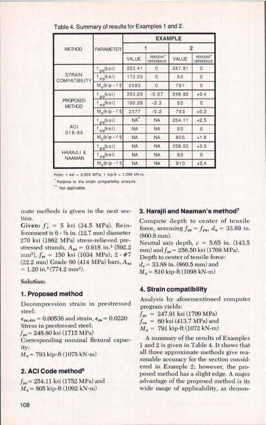
Table 4. Summary of results for Examples 1 and 2.
METHOD PARAMETER
EXAMPLE
1 2
VALUE PERCENT'DIFFERENCE VALUE PERCENTDIFFERENCE
STRAINCOMPATIBILITY
f s(k s i) 253.41 0 247.91 0
fns(ksi) 173.23 0 60 0
M n (kip-f t) 2383 0 791 0
PROPOSEDMETHOD
f s(ksi) 253.23 -0.07 248.80 +0.4
f ns(ksi) 169.28 -2.3 60 0
Mn(kip-f t) 2377 -0.2 793 +0.2
ACI318-83
f s(ksi) NA* NA 254.11 +2.5
f5(ksi) NA NA 60 0
Mn(kip-f t) NA NA 805 +1.8
HARAJLI &NAAMAN
f s(ksi) NA NA 256.50 +3.5
fns(ksi) NA NA 60 0
Mn(kip-f t) NA NA 810 +2.4
Note: 1 ksi = 6.895 MPa; 1 kip-ft = 1.356 kN-m.
Relative to the strain compatibility analysis.Not applicable.
mate methods is given in the next sec- 3. Harajli and Naaman's method?tion.Given: f = 5 ksi (34.5 MPa). Rein-forcement is 6 - 1/2 in. (12.7 mm) diameter270 ksi (1862 MPa) stress-relieved pre-stressed strands, A p8 = 0.918 in. 2 (592.2mm2 ), f3e = 150 ksi (1034 MPa); 2 - #7(22.2 mm) Grade 60 (414 MPa) bars, Any= 1.20 in. 2 (774.2 mm2).
Solution:
1. Proposed method
Decompression strain in prestressedsteel:8 ps,dec = 0.00536 and strain, e ps = 0.0220Stress in prestressed steel:fps = 248.80 ksi (1715 MPa)Corresponding nominal flexural capac-ity:M. = 793 kip-ft (1075 kN-m)
2. ACI Code methods
fp3 = 254.11 ksi (1752 MPa) andMn = 805 kip-ft (1092 kN-m)
Compute depth to center of tensileforce, assuming fp. = fpU , d,. = 33.89 in.(860.8 mm).Neutral axis depth, c = 5.65 in. (143.5mm) and f a = 256.50 ksi (1769 MPa).Depth to center of tensile force:de = 33.88 in. (860.5 mm) andM„ = 810 kip-ft (1098 kN-m)
4. Strain compatibility
Analysis by aforementioned computerprogram yields:f8 = 247.91 ksi (1709 MPa)fee = 60 ksi (413.7 MPa) andM„ = 791 kip-ft (1072 kN-m)
A summary of the results of Examples1 and 2 is given in Table 4. It shows thatall three approximate methods give rea-sonable accuracy for the section consid-ered in Example 2; however, the pro-posed method has a slight edge. A majoradvantage of the proposed method is itswide range of applicability, as demon-
108

Table 5. Parameters used in developing Figs. 8 through 16.
TYPE OF BEAMaRECTANGULAR TEE
Figure No. 8 9 10 11 12 13 14b
15c
16
CC(ksi) 5 5 7 5 5 5 5 7d
5/3
Grade ofAns (ksi)
N/A 60 60 60 270 270 N/A N/A 60
A ns / A ps 0 2 2 2 0.5 0.5 0 0 0.5
f py / f pu 0.85 0.85 0.85 0.9 0.85 0.85 0.85 0.85 0.9
d n5 / d ps N/A 1 1 1 1 1 N/A N/A 1.04
f S e f pu 0.56 0.56 0.56 0.56 0.56 0.56 VARIES 0.56 0.56
f ns, e(ks,) N/A -25 -25 -25 -25 -25 N/A N/A -25
Note: 1 ksi = 6.895 MPa.a For all beams: E ps = E ns = 28,000 ksi, A ' 5 = 0, ccu = 0.003, cpu = 0.05, fpu = 270 ksi.
bTypical 8 ft. x 24 in. PCI Double Tee.cSection dimensions correspond to beam in Example 4.2.6 of Ref. 15.dprecast/topping strength.
strated by Example 1, and further dis-cussed in the following sections.
Parametric StudiesThe proposed approximate method
includes assumption of initial values forthe steel stresses. Numerous trials weremade, for a wide range of applications,with initial steel stresses varying fromfpu to well below f,5 . It was found thatthe best accuracy was achieved by as-suming the tensile steel stresses equalto the respective yield points of the steeltypes used, and the compressive steelstress -equal to zero. The following dis-cussion of Figs. 8 through 16 further il-lustrates this finding.
Sample plots of the results of the pro-posed method, the strain compatibilitymethod, Eq. (18-3) of ACI 318-83, 5 andEqs. (21), (22), and (24) of Harajli andNaaman' are shown in Figs. 8 through16. A summary of the concrete andreinforcement parameters used in de-
veloping Figs. 8 through 16 is given inTable 5. Loov 16 has recently proposedan approximate method. Unfortunately,the final draft of Loov's paper was notavailable in time to include his methodin Figs. 8 through 16. For readers' con-venience, the methods of Refs. 5, 7, and16 are summarized in the following sec-tion. In addition, their main features arecompared with those of the proposedapproximate method.
For the parameters considered inFigs. 8 through 11, all three approximatemethods are applicable. The proposedmethod plots within about 1.5 percent ofthe strain compatibility curve, and itperforms better than Eq. (18-3) of ACI318-83 and Harajli and Naaman'smethod. In Figs. 9 through 11, f r$ wastaken equal to f5 in the proposed methodbecause the mild reinforcement yieldsbefore the prestressed reinforcementreaches fPS.
Figs. 12 and 13 show the relationshipbetween steel stress at ultimate flexure
PCI JOURNAL/September-October 1988 109

fpu 270 ksi, A ns= 0,f = 5 ksi, fpy /fpu= 0.85
1 -,
. ss
fps \ \
fpu s\ \
STRAIN COMPATIBILITY
.85 ------------ PROPOSED- - • - ACI 318-83
- - HARAJLI & NAAMAN
.8-0 .85 .1 .15 .2 .25 .3
(Apsfpu+Ansfy Asfy)/fcbdps
Fig. 8. Stress in prestressed tendon at ultimate flexure vs. total steel index.
fpu =270 ksi, Ans /Aps = 2,fc =5 ksi, fy = 60ksi, fpy/fpu=0.85
. ss
f
P
' s \Pu
STRAIN COMPATIBILITY85 ------------PROPOSED
- • - • - ACI 318-83
- - HARAJLI & NAAMAN
8'0 .05 .1 .15 .2 .25 .3
(Aps f Al ns fy Asfy)/f^bdps
Fig. 9. Stress in prestressed tendon at ultimate flexure vs. total steel index.
110

fpu = 270 ksi, A ns /A ps = 2,fc=7 ksi, fy = 60ksi, fpy/fpu=0.85
1
95
fpsf 'spu
85
V 0 .05 .1 .15 .2 .rb
Aps fpu Ans fy AS f )/ fC bdpS
Fig. 10. Stress in prestressed tendon at ultimate flexure vs. total steel index.
fps 270ksi, A ns /Aps=2,f' =5ksi,fy =60ksi,fpy /fps 0.9
'rT \.95
ps 'pu f
STRAIN COMPATIBILITY
85 ------------ PROPOSED— • — — ACI 318-83
— HARAJLI & NAAMAN
0 .05 .1 .15 .2 .25 .3
(Aps fpu+Ans fy –As fy )/fc fps
Fig. 11. Stress in prestressed tendon at ultimate flexure vs. total steel index.
PCI JOURNAL/September-October 1988 111

fpU 270ksi, Ans /Aps=0.5, f'=5ksi,fpy/fps 0.85
1 --,
.ss
fps
f 'spu
-- STRAIN COMPATIBILITY
.85 ------------ PROPOSED
.80 .05 .1 .15 .2
(Apsfpu+Ansfpu A^sfy)/fcbdps
.25 .3
Fig. 12. Stress in prestressed tendon at ultimate flexure vs. total steel index.
fpu=270ksi,A ns /Aps= 0.5, f, = 5ksi,fpy/fps 0.85
1 -
.7 '.
fns
f 5 ^'^pu
.4
3 STRAIN COMPATIBILITY----------- PROPOSED
.2
0 0 .05 .1 .15 .2 .25 .3
(Aps fpu+Ans fpu As fy)/ff bdns
Fig. 13. Stress in nonprestressed tendon at ultimate flexure vs. total steel index.
112

fpu = 270 ksi, f' = 5ksi, fpy /fpu =0.85, Ans= 0, (A psfpu /ff bdps ) = 0.15
• 96
.94
. 92
fps .88 -
fpu .86 STRAIN COMPATIBILITY —LOWER LIMIT OF
------------ PROPOSED ACI 318-83
— • — • — ACI 318-83
•84 — — HARAJLI & NAAMAN
.82
80 1 .2 .3 .4 .5 .6 .7
fse/fpu
Fig. 14. Stress in prestressed tendon at ultimate flexure vs. effective prestress.
f pu =270 ksi,A ns =0,f^=7ksi,f py / f pu =0.85 b/ bW top=8.35,
1 h / h=0. 083 ! % f 5.75" 5.75"
. 95
\-- ^ I^ ►
\3.75" 3.75"
f
f pu .s
STRAIN COMPATIBILITY
.85 ------------ PROPOSED— • — • — ACI 318-83
— HARAJLI & NAAMAN
B 0 .025 .05 .075 .1 .125 .15
A ps f pu / f^bdps
Fig. 15. Stress in prestressed tendon at ultimate flexure vs. prestressed steel index for a
typical 8 ft x 24 in. PCI double T-section.
PCI JOURNAL/September-October 1988 113

f pu = 270 ksi, A ns / A PS = 0. 5, f G top = 3 ksi, f G PC = 5 ksi, f y = 60 ksi
fI f=0.9,dns / dps =1.04,b/ bW top=3.66,h t / h=0.077,d/ h=0.154Py pu
1 dps / h = 0. 885
95b
ht:............
^`^d ns dps b^ topfpu .s
STRAIN COMPATIBILITY
.85 ------------ PROPOSED
— — • — ACI 318-83
.80 .05 .1 .15 .2 .25 .3
(A ps f pu +A ns f y —A's f y ) / fG top bdps
Fig. 16. Stress in prestressed tendon at ultimate flexure vs. total steel index for acomposite T-section.
and total reinforcement index when pre-stressed tendons are supplemented withnonprestressed tendons. In this case,neither Eq. (18-3) of ACI 318-83 norHarajli and Naaman's method is appli-cable. In Fig. 12, the proposed curve hasa maximum deviation of about 1.5 per-cent. In Fig. 13, the proposed curve de-viates by no more than about 2 percentin the lower two-thirds of the reinforce-ment range, which is where most practi-cal designs would fall. It yields veryconservative stress values in the upperthird.
Fig. 14 shows the relationship be-tween prestressed steel stress at ulti-mate flexure and effective prestress ff,,when the reinforcement index is heldconstant. The steel stress by the pro-posed method is in close agreementwith the strain compatibility method forall values of effective prestress. The
other approximate methods for deter-mining ff are limited to cases where theeffective prestress is not less than0.5 fem.
Figs. 15 and 16 show the relationshipbetween prestressed steel stress at ulti-mate flexure and total reinforcementindex for T-sections. In both figures theproposed method offers better resultsthan the other approximate methods. Itshould be noted from Fig. 15 that theACI Code method becomes increasinglyunconservative as the depth of the com-pression block, a, exceeds the flangethickness, hr. Harajli and Naaman'smethod correctly adjusts for this T-sec-tion effect.
In Fig. 16, Harajli and Naaman'smethod was omitted because their equa-tions do not explicitly show how to cal-culate fP8 when the depth of the com-pression block, a, includes more than
114

one concrete strength. An example intheir paper, however, indicates how toapply the assumptions of their methodto composite members. If their methodwere included in Fig. 16, it would indi-cate trends similar to those shown inFig. 15.
At this point, an important observationconcerning the proposed method can bemade. Although the proposed method isslightly unconservative, in some cases,with respect to the strain compatibilitymethod in Figs. 8-16, it must be notedthat these figures are based on steel withminimum ASTM properties. In reality,steel properties are significantly greaterthan minimum ASTM properties, as dis-cussed earlier.
Comparison of ApproximateMethods
A description of four approximate pro-cedures for calculation of f,, at ultimateflexure is given in Table 6. Discussionof the features of these methods is givenin Table 7. It is shown that the main ad-vantage of the proposed procedure is itsflexibility. It is applicable to currentmaterial and construction technology, aswell as possible future developments.
The ACI Code method is reasonablyaccurate and simple to use if the com-pression block is of constant width. Useof steel indexes can be confusing fornonrectangular section shapes. An im-provement of the current form wassuggested by Mattock, in his discussionof Ref. 7, as follows:
fp3 = f 11 – 0.85 yp " I (12)91
where c,, is the neutral axis depth calcu-lated assuming f 3 =f.
This modified form would combinethe benefits of both the ACI Code andHarajli and Naaman's method. The au-thors agree with Mattock's statementthat the use of d, rather than d.0 or de assuggested in Ref. 7, is more theoreticallycorrect. Further, Eq. (12) takes into ac-
count the effect of f/ f,M , and thusbrings out the advantage of using low-relaxation steel.
Loov's method appears to have amathematical form that would give abetter fit than the predominantlystraight-line relationships of the ACICode method (see Figs. 8-11 and 14-16),and Harajli and Naaman's method (seeFig. 8-11, and 14). It is limited in scope,however, to the same applications as theother two methods.
CONCLUSIONThe flexural strength theory of
bonded prestressed and partially pre-stressed concrete members is reviewedand analysis by the strain compatibilitymethod is described. A computer pro-gram for flexural analysis by the straincompatibility method is provided inBASIC for IBM PC/XT and AT mi-crocomputers and compatibles. Programusers can take advantage of higher ten-don capacities with adequatedocumentation of actual stress-straincurves. The program and its manual areavailable from the PCI for a nominalcharge.
A new approximate method for cal-culating the stress in prestressed andnonprestressed tendons at ultimate flex-ure is also presented. It is applicable tosections of any shape, composite or non-composite, with any number of steellayers, and with any type of ASTM ten-dons stressed to any level. Parametricand comparative studies indicate thatthe proposed method is more accurateand more powerful than Eq. (18-3) ofACI 318-83 and other available ap-proximate methods.
The proposed method is illustrated bytwo numerical examples and results arecompared with those of the iterativestrain compatibility method and withother approximate methods. ProposedACI 318-83 Code and Commentary revi-sions are given in Appendix B.
PCI JOURNAL/September-October 1988 115

rn Table 6. Summary of approximate methods for determining fps.
(1) PROPOSED
Steps:(1 ) Assume tensile steel stresses =
respective yield points andcompressive steel stress = 0,and use force equilibrium tocompute F0.
(2) Set F = 10.85 1' A for all C c c
concrete types in compression,and compute a.
(3) c=a/ (11.For composite sections assume
YO. 8 5( f'c Ac (3 )k 1k(i1 ave. = F c(4) Compute steel strains in each
layer T.d .lI
E =Ei cu c / i, decwhere
Ei,dec=fse/ Eior Ei, =(f t -25, 0001/ Ei
lP )whichever is applicable.
(5) Use power formula to computesteel stresses.I =E,E O+ 1-OR1/Rl <fi
(1+E i)Pu
whereE Eie =Kfpy
(2) ACI 318-835
ff ps - f Pu 1 Pp fpu + d (w m)
]]1 cConditions.If compression reinforcement is takeninto account:
uc p
and d'<0.15d .Pwherey=0. 55forf/ f>0.80p py pu
=0. 40forf/ f2 0.85py pu=0.28forf/ f _ 0.90py pu
dp = depth to prestressed tendonsd= depth to nonprestressed tension barsd = depth to compresssion barspp=Aps/bdp
e =(As/bd)(fy/fc)m' =(A's/bd)(ffy /I'C)
b = width of compression faceAP , A s , As =steel areas at depths
dP , d, & d.
(3) HARAJLI & NAAMAN7
c1PS= fpul-0.3dj
uc
or, f ps =f pu^1-0.3 lauuJ
where
de=A p t ps d p +As I ds
Af+Afpps sy
Ap 1 pu dp + A s f dsdu
yA I +A Ip pu s y
At +A 1 -Atc =
UP Pu
S y for 01 c<hAs t y
0.85P f'b+0.3-_E.-E.c uu
C
uAp f Pu +Af yA f -Ts sy
f for c?hApfpu .1 f0.85(31 t c b w +0.3 d
uT1=0.85f'c(b-bw)h1Ap =area of prestressed steeld s =depth to nonprestressed tension
bars.Other symbols are as per the ACI Code.
(4) LOOV16
1_k asfh
_f Ps
ps pu cpu1+kh dps
where
k h =2[1.04- fPy Il pu)
A s f y -A's I y -0.85f'c(b- bw)h1
csf 0.85(311.cbwdp
c __ Aps f pu
P u 0. 8 5 (3 f' b dp1 c wConditions:1) c>hf / p1otherwise treat as a rectangular section.2) c>d/ (1 -E'y / cc)Otherwise ignore compression steelin the c formula.
St
whereE'y = yield strain of compression steelE= ultimate concrete strain.c
* To obtain c e , change f pu to f ps and d u to de

Table 7. Comparison of the features of the approximate methods for determining fFS.
METHODFEATURE 6
(1) PROPOSED (2) ACI 318-83 (3) HARAJLI & NAAMAN 7 (4) LOOVt
Slightly lengthier thanSIMPLICITY Method (2) for the same Simplest where applicable Same as (1) Same as (1)
applications
Slightly less Expected to be slightly ACCURACY Very accurate Reasonable wher accurate than more accurate than
applicable method (2) method (2)
Developed for rectangular Rectangular and T CROSS SECTION Any shape sections. May be inaccurate sections. Must be modified Same as (3) SHAPE for other shapes. for other shapes.
COMPOSIT Yes NoNo. Must be modified for Same as (3)
SECTIONS more than one concrete type.
STRESSED Any type Mild bars only Same as (2) Same as (2)STEELSTEEL
NUMBER OF Ali ASTM steels. Power fomula constants Steels with f py / f pu No distinction between Valid for all
TENDON STEELTYPES can be easily determinedy = 0.80, 0.85, & 0.90 steel typesyp f py / f pu values
for future types.
NUMBER OF No limit Maximum = 3 Same as (2) Same as (2) STEEL LAYERS
Not part of original proposal,COMPRESSION Automaticall y Conditions for ieldiny g
tbut conditions were developed Condition placed on (c / d')
STEEL YIELDING checked are given later to match Method (2) to guarantee yielding.
CONDITION ONEFFECTIVE No conditions f se > 0.5 f pu f Se >_ 0.5 f pu f Se >_ 0.6 0 f py
PRESTRESS
" Relative to the strain compatibility method with conditions of Section 10.2 of ACI 318-83, and minimum ASTM standard steel properties.

REFERENCES
1. Mattock, A. H., "Flexural Strength ofPrestressed Concrete Sections by Pro-grammable Calculator," PCI JOURNAL,V. 24, No. 1, January-February 1979, pp.32-54.
2. Menegotto, M., and Pinto, P. E.,"Method of Analysis for CyclicallyLoaded R. C. Plane Frames, IncludingChanges in Geometry and Non-ElasticBehavior of Elements Under CombinedNormal Force and Bending," Interna-tional Association for Bridge and Struc-tural Engineering, Preliminary Reportfor Symposium on Resistance and Ulti-mate Deformability of Structures Actedon by Well-Defined Repeated Loads,Lisbon, Portugal, 1973, pp. 15-22.
3. Naaman, A. E., "Ultimate Analysis ofPrestressed and Partially PrestressedSections by Strain Compatibility," PCIJOURNAL, V. 22, No. 1, January-Feb-ruary 1977, pp. 32-51.
4. Naaman, A. E., "An Approximate Non-linear Design Procedure for PartiallyPrestressed Beams," Computers andStructures, V. 17, No. 2, 1983, pp. 287-293.
5. ACI Committee 318, `Building CodeRequirements for Reinforced Concrete(ACI 318-83)," American Concrete In-stitute, Detroit, Michigan, 1983.
6. Mattock, A. H., "Modification of ACICode Equation for Stress in Bonded Pre-stressed Reinforcement at Flexural Ul-timate," ACI Journal, V. 81, No. 4, July-August 1984, pp. 331-339.
7. Harajli, M. H., and Naaman, A. E.,"Evaluation of the Ultimate Steel Stressin Partially Prestressed Flexural Mem-bers," PCI JOURNAL, V. 30, No. 5,September-October 1985, pp. 54-81. Seealso discussion by A. H. Mattock andAuthors, V. 31, No. 4, July-August 1986,pp. 126-129.
8. ACI Committee 318, "Commentary onBuilding Code Requirements for Rein-forced Concrete (ACI 318-83)," (ACI318R-83), American Concrete Institute,
Detroit, Michigan, 1983, 155 pp. See alsothe 1986 Supplement.
9. Mattock, A. H., and Kriz, L. B., "UltimateStrength of Structural Concrete Memberswith Nonrectangular CompressionZones," ACI Journal, Proceedings V. 57,No. 7, January 1961, pp. 737-766.
10. Mattock, A. H., Kriz, L. B., and Hognes-tad, E., "Rectangular Concrete StressDistribution in Ultimate Strength De-sign," ACI Journal, Proceedings V. 57,No. 8, February 1961, pp. 875-928.
11. Tadros, M. K., "Expedient Service LoadAnalysis of Cracked Prestressed Con-crete Sections," PCI JOURNAL, V. 27,No. 6, November-December 1982, pp.86-111. See also discussion by Bach-mann, Bennett, Branson, Brondum-Niel-sen, Bruggeling, Moustafa, Nilson,Prasada Rao and Natarajan, Ramaswamy,Shaikh, and Author, V. 28, No. 6, No-vember-December 1983, pp. 137-158.
12. Naaman, A. E., "Partially PrestressedConcrete: Review and Recommenda-tions," PCI JOURNAL, V. 30, No. 6, No-vember-December 1985, pp. 30-71.
13. Notes on ACI 318-83 Building Code Re-quirements for Reinforced Concretewith Design Applications, Fourth Edi-tion, Portland Cement Association,Skokie, Illinois, 1984, pp. 25-31 to 25-34.
14. Skogman, B. C., "Flexural Analysis ofPrestressed Concrete Members," M. S.Thesis, Department of Civil Engineer-ing, University of Nebraska, Omaha,Nebraska, 1988.
15. PCI Design Handbook, Third Edition,Prestressed Concrete Institute, Chicago,Illinois, 1985, p. 11-18.
16. Loov, R. E., "A General Equation for theSteel Stress, ft,,, for Bonded Members,"to be published in the November-December 1988 PCI JOURNAL.
17. Proposal to ACI-ASCE Committee 423,Prestressed Concrete, on changes in theCode provisions for prestressed and par-tially prestressed concrete. Submitted byA. E. Naaman, on March 8, 1987.
118

APPENDIX A - NOTATIONThe symbols listed below supplement
and supercede those given in Chapter18 of AC 1318-83.
a = depth of equivalent rectan-gular stress block as definedin Section 10.2.7 of ACI318-83
A, = area in compression for a typeof concrete. There is only oneconcrete type in noncompos-ite construction.
A n3 ,A^,$ = areas of nonprestressed andprestressed tension rein-forcement
b = width of compression face ofmember
c = distance from extreme com-pression fiber to neutral axis
C = total compressive force incross section of member
d d = distance from extreme com-pression fiber to centroid ofsteel layer "i"
dn8 , dpi = distances from extreme com-pression fiber to centroids ofnonprestressed and prestressedtension reinforcement
d,op = overall depth of concretetopping
d' = distance from extreme com-pression fiber to centroid ofcompression steel
E = modulus of elasticity; sub-script "i" refers to reinforce-ment layer number.
E p8 = moduli of elasticity of non-prestressed and prestressedreinforcement
f^ = specified compressivestrength of concrete; secondsubscripts "pc" and "top"refer to precast (first stage)and topping (second stage)concretes, respectively.
F, = total compressive force inconcrete at ultimate flexure
fi = stress in tendon steel corre-sponding to a strain €,
Sign convention: Tensile stress insteel and compressive stress in concreteare positive.
fnB,fP$ = stress in nonprestressed andprestressed reinforcement atultimate flexure
fn8,e,fse = stress in nonprestressed andprestressed reinforcementafter allowance for time-de-pendent effects
fpE = initial tendon stress beforelosses
= specified tensile strength ofprestressing tendons
fps = specified yield strength ofprestressing tendons
f8 = stress in compressive rein-forcement at ultimate flexure
fv = specified yield strength ofnonprestressed mild rein-forcement
h = overall thickness of memberhf = thickness of flange of flanged
sectionsi = a subscript identifying the
steel layer number. A steellayer "i" is defined as a groupof bars or tendons with thesame stress-strain properties(type), the same effectiveprestress, and that can be as-sumed to have a combinedarea with a single centroid.
K, Q, R = constants used in Eq. (6)T = total tensile force in cross
sectionx(3 1 = a/c factor defined in Section
10.2.7 of ACI 318-83= [0.85 – 0.05 (f,' – 4 ksi)]
0.85 and , 0.65ecu = maximum usable compres-
sive strain at extreme con-crete fiber, normally takenequal to 0.003
E t = strain in steel layer "i" at ul-timate flexure
e,,dee = strain in steel layer "i" atconcrete decompression
PCI JOURNAL/September-October 1988 119

E ns,dec, Eps.dec = strain in nonprestressedand prestressed tensionreinforcement at con-crete decompression
eps = strain in prestressed tendonreinforcement at ultimateflexure
Epu = strain in high strength tendonat stress fr,.
epy = yield strain of prestressingtendon
es = strain in compression steel atultimate flexure
Es,dec = strain in compression steel atconcrete decompression
ACKNOWLEDGMENT
The authors wish to thank Ronald G.Dull, chairperson of the PCI Commit-tee on Prestressing Steel, the UnionWire Rope Division of Armco Inc.,Florida Wire and Cable Co., PrestressSupply Inc., Shinko Wire America Inc.,Siderius Inc., Springfield Industries
Corp., and Sumiden Wire ProductsCorp. for supplying the stress-straincurves used in the preparation of thispaper. The authors also wish to expresstheir appreciation to the reviewers ofthis article for their many helpfulsuggestions.
COMPUTER PROGRAMA package (comprising a printout of the computer program, user's manual,and diskette suitable for IBM PC/XT and AT microcomputers) is availablefrom PCI Headquarters for $20.00.
120
APPENDIX B - PROPOSED ACI 318-83 CODEAND COMMENTARY REVISIONS
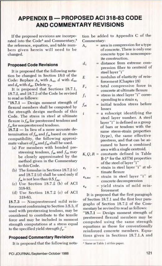
If the proposed revisions are incorpo-rated into the Code s and Commentary,'the reference, equation, and table num-bers given herein will need to bechanged.
Proposed Code Revisions
It is proposed that the following nota-tion be changed in Section 18.0 of theCode: Replace A 3 with A 3 , d with d„8,and dp with dom . Delete yp.
It is proposed that Sections 18.7.1,18.7.2, and 18.7.3 of the Code be revisedto read as follows:"18.7.1 — Design moment strength offlexural members shall be computed bythe strength design methods of thisCode. The stress in steel at ultimateflexure is f 3 for prestressed tendons andf„s for nonprestressed tendons.18.7.2 — In lieu of a more accurate de-termination of f83 and f/8 based on straincompatibility, the following approxi-mate values of f83 and f,,3 shall be used.
(a) For members with bonded pre-stressing tendons, f,,, and fib maybe closely approximated by themethod given in the Commentaryto this Code.
(b) The formulas in Sections 18.7.2 (c)and 18.7.2 (d) shall be used only iff, is not less than 0.5f8,,.
(c) Use Section 18.7.2 (b) of ACI318-83.
(d) Use Section 18.7.2 (c) of ACI318-83.
18.7.3 — Nonprestressed mild rein-forcement conforming to Section 3.5.3, ifused with prestressing tendons, may beconsidered to contribute to the tensileforce and may be included in momentstrength computations at a stress equalto the specified yield strength f3."
Proposed Commentary Revisions
tion be added to Appendix C of theCommentary:A, = area in compression for a type
of concrete. There is only oneconcrete type in noncompos-ite construction.
dt = distance from extreme com-pression fiber to centroid ofsteel layer "i"
E_ modulus of elasticity of rein-forcement (Chapter 18)
F, _ total compressive force inconcrete at ultimate flexure
fi _ stress in steel layer "i" corre-sponding to a strain Et
f>n = initial tendon stress beforelossesa subscript identifying thesteel layer number. A steellayer "i" is defined as a groupof bars or tendons with thesame stress-strain properties(type), the same effectiveprestress, and that can be as-sumed to have a combinedarea with a single centroid.
K,Q,R = constants defined in TableB-1* for the ASTM propertiesof the steel of layer "i"
Ei strain in steel layer "i" at ul-timate flexure
Ej.dec = strain in steel layer "i" atconcrete decompression
EY = yield strain of mild rein-forcement
It is proposed that the first paragraphof Section 18.7.1 and the first four para-graphs of Section 18.7.2 of the Com-mentary be revised to read as follows:"18.7.1 — Design moment strength ofprestressed flexural members may becomputed using the same strengthequations as those for conventionallyreinforced concrete members. Equa-tions given in Sections 18.7.1.A and
It is proposed that the following nota- * Same as Table 1 of this paper.
PCI JOURNAL/September-October 1988 121

18.7.1.B of the Commentary are validexcept when nonprestressed tendonreinforcement is used in place of mildtension reinforcement. In this case thestress in the nonprestressed tendon re-inforcement, f.^s , should be used insteadoffs.18.7.2 — A microcomputer program fordetermining flexural strength by thestrain compatibility method, using theassumptions given in Section 10.2, isavailable from Refs. A and B.* In lieu ofthe iterative computer analysis, the fol-lowing approximate procedure may beused for determining the stress, fi, inany steel layer "i". A layer "i" is definedas a group of bars or tendons with thesame stress-strain properties (type), thesame effective prestress, and that can beassumed to have a combined area with asingle centroid. The procedure givenbelow is valid regardless of the sectionshape, number of concrete types in thesection, number of steel layers, andlevel of effective prestress, f3.
A. General Case — Noncompositeor Composite Cross Sections ofGeneral Shape with any Number ofSteel Layers
Step 1: Initially assume the tensile steelstresses equal to the respective yieldpoints of the steel types used and thecompressive steel stress equal to zero,and use force equilibrium (T = C) tocompute the total compressive force inconcrete, F.
Step 2: Using the provisions of Section10.2.7, compute the depth of the stressblock, a. For composite sections, theforce Fe may have more than one com-ponent, 0.85f, A e , where f,' and A e arethe strength and area in compression ofeach concrete part in the section.Step 3: Compute the neutral axis depth
* Refs. A and B correspond to this paper and Ref. 14,respectively.t Same as Table 1 of this paper.
c = al f3,. For composite sections, as-sume an average /3 1 as follows:
10.85(f^Ac/31)ka1 ave.= F (B-1)
c
where k is the concrete type number.Step 4: Compute the strain in each steellayer "i" by:
E i = 0.003 I t̂ – i) + E i.dec (B-2)
\ c /
where E l,dec may be approximated asf^/E;. If a layer consists of partially ten-sioned tendons, E {,de, may be taken = (fr,– 25,000 psi)/E where f = initial pre-stress, psi. For nonprestressed tendonsor mild bars, E i,dec may be taken =–25,000 psi/E1.
Step 5: Compute the stress in each ten-don steel layer "i" by:
.fi = EtE I Q + 1 Q 1 R
J < .f^. (B-3)
L (1 +Ei
where
EjE
E; _ (B-4)Kff1,
The constants E, K, Q, and R dependon the stress-strain properties of thetendon steel type used. For steels satis-fying minimum ASTM standards, valuesfor these constants may be taken fromTable B-1.t The stress in mild rein-forcement layers may be found usingSection 10.2.4.
Step 6: If additional accuracy is desired,an improved value of a may be obtainedby repeating Steps 1 and 2 with the steelstresses from Step 5. Take momentsabout any level in the section to com-pute the flexural strength, M,,.
B. Special Case — NoncompositeSections with Uniform Compres-sion Block Width and up to ThreeSteel Layers: prestressed tension
122

tendons, nonprestressed tensionmild bars, and nonprestressedcompression mild bars
This special case is the only one ad-dressed in the 1983 Edition of the Code.For this case, the first four steps of Pro-cedure A reduce to the following for-mula:
e i = 0.003 0.85 f b /3, dt 1 + et.,ec
(B-5)
where "i" refers to ps, ns, or s'. Thesteel stress in each layer "i" may then becalculated by Eqs. (B-3) and (B-4). Nor-mally, mild tension bars yield at ulti-mate flexure, i.e., e i ' e,. It is important,however, to apply Eq. (B-5) to the com-pression steel layer to verify yielding.
C. Improvements over the1983 Code
The procedures described in SectionsA and B provide the following advan-tages over Eq. (18-3) of the 1983 Code.
1. Steel stresses are more accuratelydetermined.
2. The proposed method is valid forall levels of effective prestress. Thus, itis applicable to sections where both pre-stressed and nonprestressed tendons areincluded.
3. The method is not limited to sec-tions where the equivalent rectangularstress block is of uniform width. Thus, itis applicable to all cross-sectionalshapes.
4. Composite sections with more thanone f,' can be analyzed."
NOTE: Discussion of this paper is invited. Please submityour comments to PCI Headquarters by June 1, 1989.
PCI JOURNAUSeptember-October 1988 123
Related Documents