http://pil.sagepub.com/ and Applications Engineers, Part L: Journal of Materials Design Proceedings of the Institution of Mechanical http://pil.sagepub.com/content/218/4/321 The online version of this article can be found at: DOI: 10.1177/146442070421800406 321 2004 218: Proceedings of the Institution of Mechanical Engineers, Part L: Journal of Materials Design and Applications T Valente, C Bartuli, M Sebastiani and F Casadei Finite element analysis of residual stress in plasma-sprayed ceramic coatings Published by: http://www.sagepublications.com On behalf of: Institution of Mechanical Engineers can be found at: Applications Proceedings of the Institution of Mechanical Engineers, Part L: Journal of Materials Design and Additional services and information for http://pil.sagepub.com/cgi/alerts Email Alerts: http://pil.sagepub.com/subscriptions Subscriptions: http://www.sagepub.com/journalsReprints.nav Reprints: http://www.sagepub.com/journalsPermissions.nav Permissions: http://pil.sagepub.com/content/218/4/321.refs.html Citations: What is This? - Oct 1, 2004 Version of Record >> by guest on September 6, 2012 pil.sagepub.com Downloaded from

Welcome message from author
This document is posted to help you gain knowledge. Please leave a comment to let me know what you think about it! Share it to your friends and learn new things together.
Transcript
http://pil.sagepub.com/and Applications
Engineers, Part L: Journal of Materials Design Proceedings of the Institution of Mechanical
http://pil.sagepub.com/content/218/4/321The online version of this article can be found at:
DOI: 10.1177/146442070421800406
321 2004 218:Proceedings of the Institution of Mechanical Engineers, Part L: Journal of Materials Design and Applications
T Valente, C Bartuli, M Sebastiani and F CasadeiFinite element analysis of residual stress in plasma-sprayed ceramic coatings
Published by:
http://www.sagepublications.com
On behalf of:
Institution of Mechanical Engineers
can be found at:ApplicationsProceedings of the Institution of Mechanical Engineers, Part L: Journal of Materials Design andAdditional services and information for
http://pil.sagepub.com/cgi/alertsEmail Alerts:
http://pil.sagepub.com/subscriptionsSubscriptions:
http://www.sagepub.com/journalsReprints.navReprints:
http://www.sagepub.com/journalsPermissions.navPermissions:
http://pil.sagepub.com/content/218/4/321.refs.htmlCitations:
What is This?
- Oct 1, 2004Version of Record >>
by guest on September 6, 2012pil.sagepub.comDownloaded from
Finite element analysis of residual stress inplasma-sprayed ceramic coatings
T Valente1, C Bartuli1�, M Sebastiani1 and F Casadei2
1Department of Chemical and Materials Engineering, University of Rome ‘La Sapienza’, Rome, Italy2Centro Sviluppo Materiali Spa, Rome, Italy
Abstract: A numerical study was carried out by finite element analysis (FEA) for the calculation of
absolute values and through-thickness variation of residual stress originating in thermal spray coatings.
The investigated deposit was an air plasma sprayed alumina coating sprayed on a carbon steel substrate pre-
viously coated with Ni20Al bond coat. Results show compressive residual in-plane stresses with linear
through-thickness variation and tensile normal and shear stresses having a peak at the coating–substrate
interface. The influence of deposition temperature on residual stress was also investigated. The experimental
validation of the FEA model was carried out using a high-speed hole drilling technique, suitably adapted
for the analysis of a multimaterial structure through FEA calculation of the required calibration coefficients.
A very good agreement between simulated and measured stresses was obtained, inspite of the adopted
simplification hypothesis.
Keywords: residual stress, plasma spray, ceramic coating, finite element, hole drilling
1 INTRODUCTION
Residual stresses originating within thermal sprayed coat-
ings in different stages of their production process can
strongly affect their mechanical properties and therefore
play a key role in their functionality and in the lifetime of
coated components. Thus, it is important to understand the
evolution of the stresses during the coating process and to
investigate the influence of processing parameters on their
absolute value and spatial distribution.
In particular, residual stresses are known to depend firstly
on the deposition temperature and secondly on particle
temperature and velocity, on deposition rate and, most
importantly, on coating thickness [1–3]. They also have a
fundamental influence on coating structure and substrate–
coating adhesion, thus strongly affecting deposit perform-
ance in working conditions.
Different experimental techniques are available nowa-
days for their direct measurement or indirect evaluation
[4–10], such as X-ray or neutron diffraction methods, cur-
vature measurements, high-speed hole drilling techniques
and metallurgical and layer removal methods. However,
numerical modelling tools [11, 12] offering reliable
predictions of the mechanical properties of a selected
substrate–coating system on the basis of the operating con-
ditions of the manufacturing process are of even greater
importance, assisting processing parameter optimization
procedures, saving time and reducing the economic impact
of the trial and error approach.
Residual stress evaluation for plasma-sprayed coatings by
finite element analysis (FEA) is a complex problem owing
to the relevant number of processing parameters involved
which can result in non-independent sources of stress con-
tributing to the final state. Such stresses are generally classi-
fied as ‘quenching stresses’ and ‘DTC stresses’, originating
from differential thermal contractions.
Quenching stresses [13–15] arise from impact, spreading
and solidification of each molten particle (at temperature
Tm) on the substrate surface. They are always tensile
and can be, in principle, approximately estimated by the
following equation
s0 ¼ E0
ðTm
Ts
ac(T) dT (1)
where Tm is the coating melting temperature, Ts is the sub-
strate temperature and ac is the coating thermal expansion
coefficient.
Several sources of error, however, can affect equation (1),
usually giving results that do not match experimental data
The MS was received on 6 February 2004 and was accepted after revisionfor publication on 15 June 2004.�Corresponding author: Department of Chemical and Materials Engineer-ing, University of Rome ‘La Sapienza’, Via Eudossiana 18, 00184 Rome,Italy.
321
L00604 # IMechE 2004 Proc. Instn Mech. Engrs Vol. 218 Part L: J. Materials: Design and Applications
by guest on September 6, 2012pil.sagepub.comDownloaded from
with good accuracy [13]; among the most important, two
need to be mentioned:
1. Young’s modulus of sprayed materials is very different
from the elastic modulus of the corresponding bulk
materials (with values of the Ec/Eb ratio as low as 1/
10), mainly as a consequence of coating porosity and
lamellar microstructure.
2. Stress relaxation phenomena [13] (creep and yielding for
metals, microcracking for ceramics) can be responsible for
a remarkable decrease in the final value of quenching stress.
In the case of metallic materials, equation (1) can thus be
modified as follows
sq ¼ E�c
ðbTm
Ts
ar(T) dT (2)
where E�c is the actual elastic modulus of the coating, as
determined by experimental measurements, and b is a temp-
erature reduction coefficient (approximately equal to about
0.6) adopted to take into account stress relaxation phenom-
ena such as yielding or creep.
On the other hand, for ceramic-based coatings, a very
marked reduction in quenching stress has also been
observed [1, 16, 17], produced as a consequence of exten-
sive microcracking of individual lamellae after droplet
impact. As an example, a residual tensile stress of about
10 MPa can be experimentally evaluated by in situ curva-
ture measurements for plasma-sprayed alumina [13], while
quenching stresses of the order of GPa would be obtained
simply by applying equation (1).
This aspect simplifies the numerical evaluation of the
total stress generated within ceramic coatings, and the con-
tribution of quenching stresses can be taken into account
simply by superimposing a uniform tensile stress, typically
in the range 10–15 MPa, to the thermally induced stress
fields [13]. This last source of stress results from misfit
strains generated by differential thermal contractions
(DTCs) [15, 18] caused by thermal expansion coefficient
(CTE) mismatch between coating and substrate; in particu-
lar, DTC stresses are induced during the final cooling stage
from processing temperature, Ts, to room temperature, Tr.
The equation correlating these misfit strains to the ther-
mal properties of the substrate and coating is as follows
D1 ¼ðTs
Tr
½ac(T)� as(T)� dT (3)
whereas is the coefficient of thermal expansion of the substrate.
Starting from equation (3), residual stress can be evalu-
ated, in the case of linear elastic material behaviour,
simply by applying the well-known Hooke’s law
sth ¼ Er
1� nc
ðTs
Tr
½ac(T)� as(T)� dT (4)
where nc is Poisson’s ratio of the coating. Equation (4)
shows that, for ac , as compressive thermal stresses arise
in the coating owing to final cooling after spraying.
Moreover, the CTE is a function of temperature, so that
thermal stresses can also arise within individual layers if
through-thickness thermal gradients are originated. This is
generally the case when the heat flux generated by the
plasma torch is repeatedly transferred to the substrate and
to the deposited layers during coating build-up.
Although complex interactions between coexisting resi-
dual stresses of various sources can be generally expected,
a sufficiently reliable prediction model can be developed
for qualitative stress estimation and preliminary process
optimization by adopting realistic simplification hypoth-
eses. The following assumptions are proposed:
1. The coating thickness is negligible compared with the
substrate thickness.
2. Spraying is carried out in constant substrate temperature
conditions (Ts).
3. The sprayed deposit is instantly quenched to Ts.
4. The substrate–deposit couple remains isothermal as it
cools down to room temperature.
5. The mechanical behaviour of the coating material is
linear elastic in the cooling range.
6. Interface bonding between the deposit and the substrate
is perfect.
On the basis of the above simplifications, the final residual
stress state can be expressed as the sum of quenching stres-
ses, sq and DTC stresses, sth
sr ¼ sq þ sth (5)
The aim of the present study is to evaluate, by using finite
element analysis (FEA) [11, 14, 19, 20], average values
and spatial distributions of DTC stresses in thermal sprayed
ceramic coatings. Experimental validation of the model was
carried out using a suitable implementation of the incremen-
tal hole drilling method [21], adapted to the analysis of
plasma-sprayed deposits by developing a further FEA
model for the calculation of calibration coefficients [22–24]. Both FEA simulation and experimental measurements
were carried out for commercialy pure alumina coatings
deposited by air plasma spraying (APS) onto AISI 4037
carbon steel substrates previously coated with a Ni20Al
bonding layer.
2 FINITE ELEMENT MODELLING
The developed model was implemented using ANSYSw 7.0
software. The complexity of the analytical process made
it expedient to carry out the modelling procedure in two
consecutive steps:
1. In the first analytical step the aim was to simulate the ther-
mal history of the coating during spraying, in order to cal-
culate the effective deposition temperature of each layer.
322 T VALENTE, C BARTULI, M SEBASTIANI AND F CASADEI
Proc. Instn Mech. Engrs Vol. 218 Part L: J. Materials: Design and Applications L00604 # IMechE 2004
by guest on September 6, 2012pil.sagepub.comDownloaded from
2. In the second step a structural analysis was performed to
estimate the residual stresses by applying the boundary
thermal conditions obtained from the previous step, and
by further implementing the final cooling phase.
2.1 Thermal history
In a thermal spray process a source of thermal and kinetic
energy is used to melt and accelerate the starting powders
towards a solid substrate where successive layers are
deposited. In the case of the APS deposition technique, a
high energy density plasma is generated electrically within
the spraying torch. The heat flux generated by each pass of
the torch was estimated by a numerical analysis procedure
based on a proprietary one-dimensional Fortran code.
Among other features, the analysis requires the calcu-
lation of the heat exchange coefficient between the plasma
jet and the substrate, starting from the plasma processing
parameters. To this end, the Holger approach [25] was
adopted, based on the equation
Nu ¼ D
r
1� 1:1(D=r)
1þ 0:1((H=D)� 6)(D=r)Pr0:42F(Re) ¼ hD
K
ð6Þ
where
D ¼ nozzle diameter
H ¼ torch–substrate distance
Pr ¼ cpg � mg
kg(Prandtl number)
cpg ¼ specific heat of the plasma gas
mg ¼ viscosity of the plasma gas
kg ¼ thermal conductivity of the plasma gas
Re ¼ rgjvg � vpjdpmg
(Reynolds number)
rg ¼ density of the plasma gas
vg ¼ velocity of the plasma gas
dp ¼ average diameter of the particles in the plasma jet
Vp ¼ velocity of the particles in the plasma jet
r ¼ 2:5D
K ¼ thermal conductivity of the substrate
h ¼ heat exchange coefficient
The function F(Re) is defined as:
F(Re) ¼ 1:36Re0:574 if 2000 , Re , 30 000
F(Re) ¼ 0:54Re0:667 if 30 000 , Re , 120 000
F(Re) ¼ 0:151Re0:775 if 120 000 , Re , 400 000
The thermal flux, _qq, transferred to the substrate (or to the
coating/substrate system) can be expressed as a function
of the heat exchange coefficient, h (obtained for calculated
Reynolds numbers in the range 1500–40 500) by the fol-
lowing equation
_qq ¼ h(Tg � Ts) ¼ K@T
@x(7)
where Ts is the temperature of the substrate or the substrate/
coating system and x is the distance from the substrate.
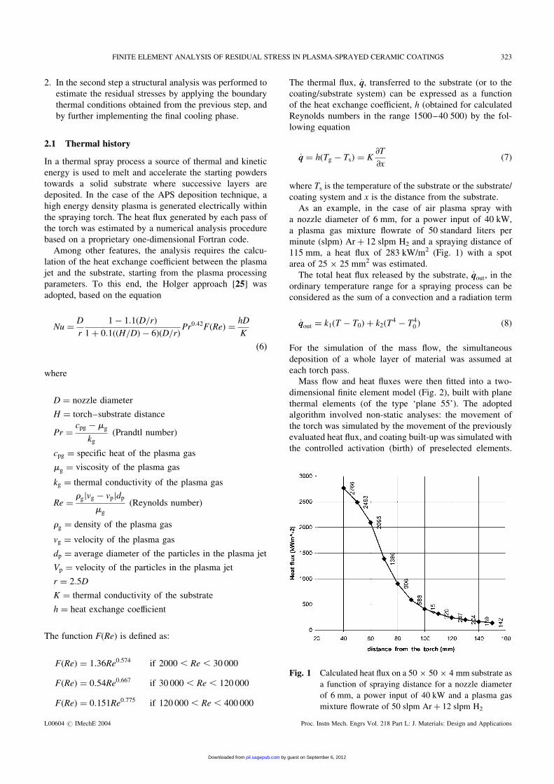
As an example, in the case of air plasma spray with
a nozzle diameter of 6 mm, for a power input of 40 kW,
a plasma gas mixture flowrate of 50 standard liters per
minute (slpm) Arþ 12 slpm H2 and a spraying distance of
115 mm, a heat flux of 283 kW/m2 (Fig. 1) with a spot
area of 25 � 25 mm2 was estimated.
The total heat flux released by the substrate, _qqout, in the
ordinary temperature range for a spraying process can be
considered as the sum of a convection and a radiation term
_qqout ¼ k1(T � T0)þ k2(T4 � T4
0 ) (8)
For the simulation of the mass flow, the simultaneous
deposition of a whole layer of material was assumed at
each torch pass.
Mass flow and heat fluxes were then fitted into a two-
dimensional finite element model (Fig. 2), built with plane
thermal elements (of the type ‘plane 55’). The adopted
algorithm involved non-static analyses: the movement of
the torch was simulated by the movement of the previously
evaluated heat flux, and coating built-up was simulated with
the controlled activation (birth) of preselected elements.
Fig. 1 Calculated heat flux on a 50 � 50 � 4 mm substrate as
a function of spraying distance for a nozzle diameter
of 6 mm, a power input of 40 kW and a plasma gas
mixture flowrate of 50 slpm Arþ 12 slpm H2
FINITE ELEMENT ANALYSIS OF RESIDUAL STRESS IN PLASMA-SPRAYED CERAMIC COATINGS 323
L00604 # IMechE 2004 Proc. Instn Mech. Engrs Vol. 218 Part L: J. Materials: Design and Applications
by guest on September 6, 2012pil.sagepub.comDownloaded from
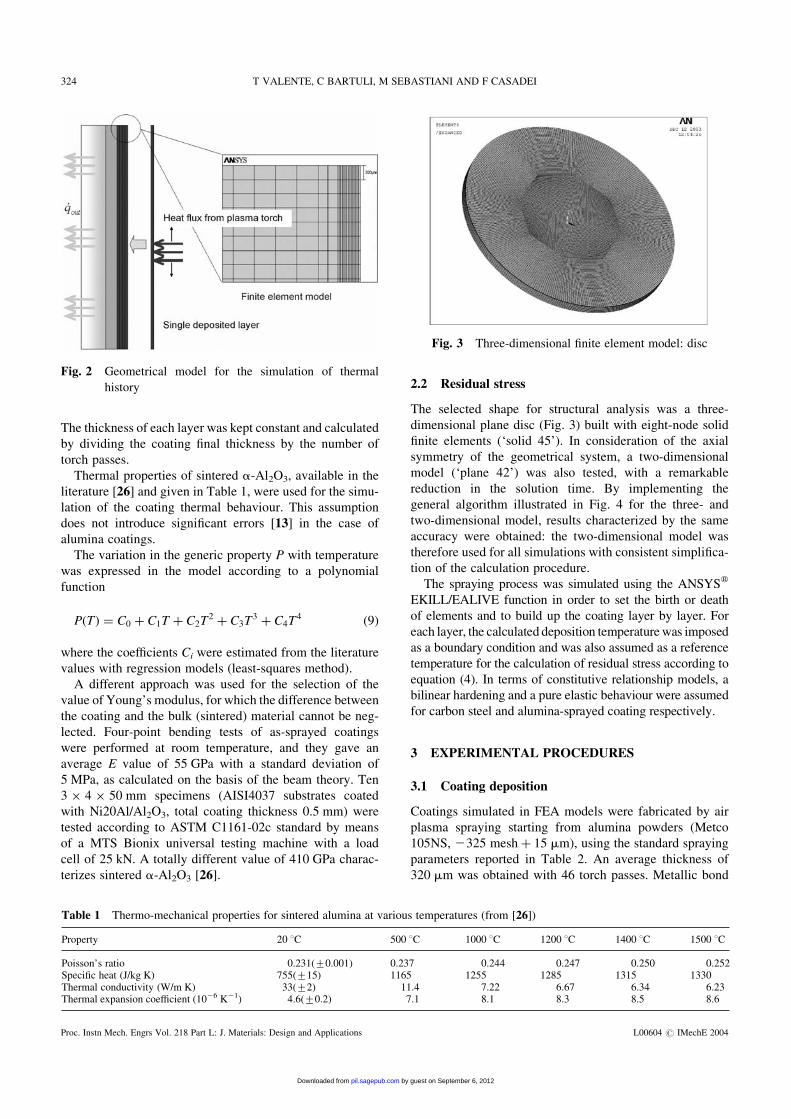
The thickness of each layer was kept constant and calculated
by dividing the coating final thickness by the number of
torch passes.
Thermal properties of sintered a-Al2O3, available in the
literature [26] and given in Table 1, were used for the simu-
lation of the coating thermal behaviour. This assumption
does not introduce significant errors [13] in the case of
alumina coatings.
The variation in the generic property P with temperature
was expressed in the model according to a polynomial
function
P(T) ¼ C0 þ C1T þ C2T2 þ C3T
3 þ C4T4 (9)
where the coefficients Ci were estimated from the literature
values with regression models (least-squares method).
A different approach was used for the selection of the
value of Young’s modulus, for which the difference between
the coating and the bulk (sintered) material cannot be neg-
lected. Four-point bending tests of as-sprayed coatings
were performed at room temperature, and they gave an
average E value of 55 GPa with a standard deviation of
5 MPa, as calculated on the basis of the beam theory. Ten
3 � 4 � 50 mm specimens (AISI4037 substrates coated
with Ni20Al/Al2O3, total coating thickness 0.5 mm) were
tested according to ASTM C1161-02c standard by means
of a MTS Bionix universal testing machine with a load
cell of 25 kN. A totally different value of 410 GPa charac-
terizes sintered a-Al2O3 [26].
2.2 Residual stress
The selected shape for structural analysis was a three-
dimensional plane disc (Fig. 3) built with eight-node solid
finite elements (‘solid 45’). In consideration of the axial
symmetry of the geometrical system, a two-dimensional
model (‘plane 42’) was also tested, with a remarkable
reduction in the solution time. By implementing the
general algorithm illustrated in Fig. 4 for the three- and
two-dimensional model, results characterized by the same
accuracy were obtained: the two-dimensional model was
therefore used for all simulations with consistent simplifica-
tion of the calculation procedure.
The spraying process was simulated using the ANSYSw
EKILL/EALIVE function in order to set the birth or death
of elements and to build up the coating layer by layer. For
each layer, the calculated deposition temperaturewas imposed
as a boundary condition and was also assumed as a reference
temperature for the calculation of residual stress according to
equation (4). In terms of constitutive relationship models, a
bilinear hardening and a pure elastic behaviour were assumed
for carbon steel and alumina-sprayed coating respectively.
3 EXPERIMENTAL PROCEDURES
3.1 Coating deposition
Coatings simulated in FEA models were fabricated by air
plasma spraying starting from alumina powders (Metco
105NS, 2325 meshþ 15 mm), using the standard spraying
parameters reported in Table 2. An average thickness of
320 mm was obtained with 46 torch passes. Metallic bond
Fig. 2 Geometrical model for the simulation of thermal
history
Table 1 Thermo-mechanical properties for sintered alumina at various temperatures (from [26])
Property 20 8C 500 8C 1000 8C 1200 8C 1400 8C 1500 8C
Poisson’s ratio 0.231(+0.001) 0.237 0.244 0.247 0.250 0.252Specific heat (J/kg K) 755(+15) 1165 1255 1285 1315 1330Thermal conductivity (W/m K) 33(+2) 11.4 7.22 6.67 6.34 6.23Thermal expansion coefficient (1026 K21) 4.6(+0.2) 7.1 8.1 8.3 8.5 8.6
Fig. 3 Three-dimensional finite element model: disc
324 T VALENTE, C BARTULI, M SEBASTIANI AND F CASADEI
Proc. Instn Mech. Engrs Vol. 218 Part L: J. Materials: Design and Applications L00604 # IMechE 2004
by guest on September 6, 2012pil.sagepub.comDownloaded from
coats with an average thickness of 180 mm were obtained
from Ni20Al powders (Metco 404NS, 2170þ 270 mesh).
X-ray diffraction patterns of as-sprayed coatings revealed
a dual-phase microstructure composed of a-Al2O3 and
g-Al2O3. A coating cross-section is shown in Fig. 5.
3.2 Residual stress measurement
Residual stresses of as-sprayed coatings were experimen-
tally evaluated using the hole drilling technique on the
basis of an incremental method [21, 27]. The procedure con-
sists of the removal of stressed material by drilling a small
blind hole in the top surface of the coating, and of the
measurement of the strain relaxation occurring in the adja-
cent material by means of a proper set of strain gauges.
By means of suitable stress–strain relationships, residual
stresses can be evaluated provided that correct values for
calibration coefficients [22, 28] are adopted. The most
widely used method for calculating residual stresses from
measured relaxed strains is the ‘integral method’ [22]:
stress values are obtained from the strain relaxation
measured at various depths with a rosette strain gauge on
the basis of the following set of equations
Xj¼i
j¼1
�AAijPj ¼ pi, 1 4 j 4 i 4 nc
Xj¼i
j¼1
�BBijQj ¼ qi, 1 4 j 4 i 4 nc
Xj¼i
j¼1
�BBijTj ¼ ti, 1 4 j 4 i 4 nc (10)
where
Pj ¼ s(1) j þ s(3) j
2, Qj ¼ s(1) j � s(3) j
2,
T j ¼ t(13) j (11)
pi ¼ 1(1)i þ 1(3)i2
, q j ¼ 1(1)i � 1(3)i2
,
ti ¼ 1(3)i þ 1(1)i � 21(2)i2
(12)
represent stress and strain components in the direction of the
three strain gauges (Fig. 6) in accordance with the nc steps in
to which the calculation is divided.
The terms Pj and pi represent the hydrostatic component
of residual stresses and the corresponding volumetric strain
relaxation. Similarly, the other variables (Qj, Tj, qi, ti) rep-
resent the shear stresses and the shear strain components.
The problem can only be solved if the two matrices of
calibration constants Aij and Bij appearing in equation (10)
(the first relating to the hydrostatic stress component, the
second to the deviatoric one) are known. Since this is
not the case for blind holes, for which closed analytical
Fig. 4 Algorithm adopted for the simulation of residual
stresses
Table 2 Spraying parameters for the alumina
coating
APS spraying parameters for Al2O3
Substrate AISI 4037 steelSpraying distance 115 mmGas plasma (slpm) 50Ar, 12H2
Plasma current 560 APlasma voltage 73 VNumber of torch passes 46Cooling gas Ar, 4.5 barCoating thickness 320 mm
Fig. 5 Microstructure of an air plasma sprayed Al2O3 coating
(cross-section, optical microscope, �200)
FINITE ELEMENT ANALYSIS OF RESIDUAL STRESS IN PLASMA-SPRAYED CERAMIC COATINGS 325
L00604 # IMechE 2004 Proc. Instn Mech. Engrs Vol. 218 Part L: J. Materials: Design and Applications
by guest on September 6, 2012pil.sagepub.comDownloaded from
solutions are not available, calibration constants were calcu-
lated by FEA. The adopted procedure to evaluate the general
term Aij requires the application of a uniform pressure at the
jth step for a hole i steps deep (Fig. 7), and the calculation of
the corresponding deformation on the gauge area [29].
Furthermore, the number and distribution of selected
steps has to be selected with the maximum care: it has
been demonstrated [30] that this number should not be
higher than 10. A step distribution that makes it possible
to minimize experimental errors is achieved if the following
conditions are met
Ann ¼ cos t, 1 4 n 4 nc
Bnn ¼ cos t, 1 4 n 4 nc (13)
These conditions are substantially subjected by adopting an
increasing distribution of calculation steps. In general, the
total number of calculation steps, nc, is different from the
number of experimental steps, ne. The experimental number
is commonly greater, which allows for a better interpolation
of strain data. In this case a continuous strain–depth (1–h)curve is available for the optimization of the calculation
step process. For better precision of the developed model,
the eccentricity of the actual drilled hole was also taken into
account using appropriate geometric relations [31] describing
the real strain distribution created around the hole.
Experimental measurements were carried out using a
high-velocity drilling machine (Restan, 350 000 r/min),
which allows for minimization of the stresses induced by
drilling and accurate measurement of the hole size and
eccentricity. To avoid induced thermal strains during
the drilling process, possibly generated owing to the low
thermal conductivity of the ceramic coatings, a stop time
of 100 s between each drilling step was adopted.
4 RESULTS AND DISCUSSION
4.1 Results of thermal analyses
The substrate temperature was monitored during spraying
by three thermocouples placed on the back of the substrate,
Fig. 7 FEM model for the calculation of calibration
coefficient A32
Fig. 6 Rosette strain gauge for hole drilling measurements
Fig. 8 Measured substrate temperature during spraying
Fig. 9 Simulation of the variation in substrate temperature
during spraying
326 T VALENTE, C BARTULI, M SEBASTIANI AND F CASADEI
Proc. Instn Mech. Engrs Vol. 218 Part L: J. Materials: Design and Applications L00604 # IMechE 2004
by guest on September 6, 2012pil.sagepub.comDownloaded from
as reported in Fig. 8. A very good agreement is observed
between the measured and the numerically predicted
temperature values (Fig. 9) with maximum differences of
2 K over the whole temperature profile. The developed
thermal model can thus be considered, for the investigated
case, as an appropriate simulation model. The substrate
temperature was maintained at a maximum value of 415 K
by appropriate gas front cooling, with the aim of reducing
the amount of residual stress after final cooling to room
temperature.
4.2 Results of structural analysis
The first qualitative results in terms of stress evaluation can
be obtained by the analysis of the deformed shape of the
coating element, as illustrated in Fig. 10: the curvature of
the coated specimen indicates the presence of compressive
stresses on the top of the coating and tensile stresses on
the back of the substrate. This is in agreement with equation
(4) since the thermal expansion coefficient of alumina is
lower than that of the carbon steel substrate.
The results of the simulation of through-thickness vari-
ation of in-plane stress are reported in Fig. 11. The graph
refers to a middle section of the system and indicates a com-
pressive in-plane stress linearly varying through the coating
thickness. At the two interfaces (coating/bond coat and bond
coat/substrate) the model predicts discontinuities leading to
tensile stresses in the bond coat and in the substrate. Look-
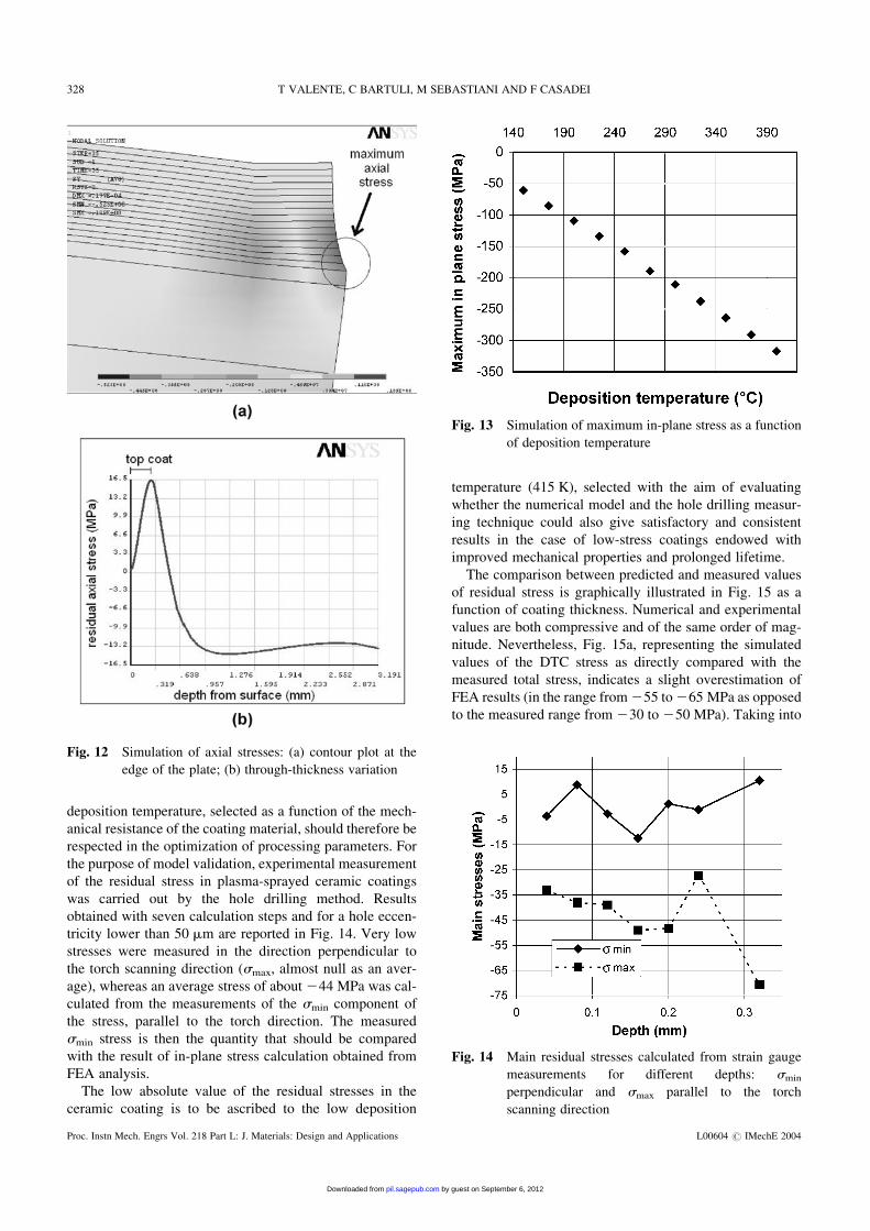
ing at the free edge of the coated substrate (Fig. 12), the
model predicts a peak in the axial stress as well as in the
shear stress, in accordance with the interface. This result
is consistent with problems observed in practice that lead
to coating detachment and delamination in this area, thus
confirming the strong influence, predicted by the model,
of residual stresses on coating adhesion [32].
Coating thickness is a fundamental parameter for control-
ling the occurrence of the above-mentioned problem:
according to the model, the value of compressive in-plane
stresses decreases with coating thickness. With the same
model, the effect of variation in the deposition tempera-
ture on residual stress can also be evaluated. Simulated
in-plane maximum stresses corresponding to spraying temp-
eratures varying from 150 to 400 8C are reported in Fig. 13.
It appears that an eccessively high deposition temperature,
while responsible for improved coating cohesion and
reduced coating porosity, can lead to residual stresses able
to promote coating failure. Appropriate upper limits in the
Fig. 10 Simulation of the deformed shape of a coating element after spraying and cooling at room temperature
Fig. 11 Simulation of through-thickness variation of residual
in-plane stress
FINITE ELEMENT ANALYSIS OF RESIDUAL STRESS IN PLASMA-SPRAYED CERAMIC COATINGS 327
L00604 # IMechE 2004 Proc. Instn Mech. Engrs Vol. 218 Part L: J. Materials: Design and Applications
by guest on September 6, 2012pil.sagepub.comDownloaded from
deposition temperature, selected as a function of the mech-
anical resistance of the coating material, should therefore be
respected in the optimization of processing parameters. For
the purpose of model validation, experimental measurement
of the residual stress in plasma-sprayed ceramic coatings
was carried out by the hole drilling method. Results
obtained with seven calculation steps and for a hole eccen-
tricity lower than 50 mm are reported in Fig. 14. Very low
stresses were measured in the direction perpendicular to
the torch scanning direction (smax, almost null as an aver-
age), whereas an average stress of about 244 MPa was cal-
culated from the measurements of the smin component of
the stress, parallel to the torch direction. The measured
smin stress is then the quantity that should be compared
with the result of in-plane stress calculation obtained from
FEA analysis.
The low absolute value of the residual stresses in the
ceramic coating is to be ascribed to the low deposition
temperature (415 K), selected with the aim of evaluating
whether the numerical model and the hole drilling measur-
ing technique could also give satisfactory and consistent
results in the case of low-stress coatings endowed with
improved mechanical properties and prolonged lifetime.
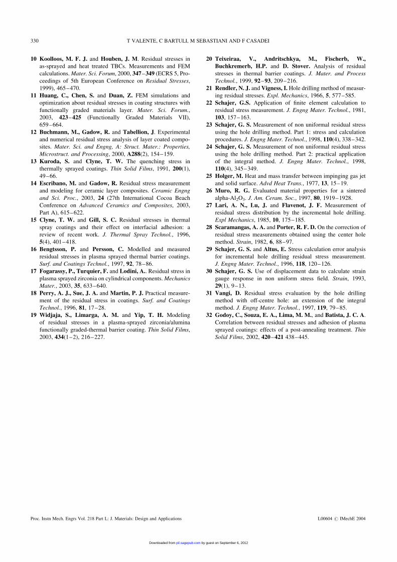
The comparison between predicted and measured values
of residual stress is graphically illustrated in Fig. 15 as a
function of coating thickness. Numerical and experimental
values are both compressive and of the same order of mag-
nitude. Nevertheless, Fig. 15a, representing the simulated
values of the DTC stress as directly compared with the
measured total stress, indicates a slight overestimation of
FEA results (in the range from255 to265 MPa as opposed
to the measured range from 230 to 250 MPa). Taking into
Fig. 14 Main residual stresses calculated from strain gauge
measurements for different depths: smin
perpendicular and smax parallel to the torch
scanning direction
Fig. 12 Simulation of axial stresses: (a) contour plot at the
edge of the plate; (b) through-thickness variation
Fig. 13 Simulation of maximum in-plane stress as a function
of deposition temperature
328 T VALENTE, C BARTULI, M SEBASTIANI AND F CASADEI
Proc. Instn Mech. Engrs Vol. 218 Part L: J. Materials: Design and Applications L00604 # IMechE 2004
by guest on September 6, 2012pil.sagepub.comDownloaded from
account the presence of tensile quenching stresses of about
10–15 MPa, results of numerical calculation appear to be in
very good agreement with measured values, as illustrated in
Fig. 15b.
5 CONCLUSIONS
A finite element model to simulate residual stresses for air
plasma sprayed ceramic coatings was developed and
validated. The model makes it possible to predict the
thermal history of the coating during the spraying process,
and the through-thickness variation of in-plane normal and
shear stresses. An agreement between the predicted and
experimental results in the coating was observed.
Numerical simulation at a low residual stress level in the
case of brittle ceramic coatings should be corrected to con-
sider effects of tensile quenching stress, in order to repro-
duce the experimental data with the best accuracy. When
residual stresses, expected or predicted, exceed 100 MPa,
quenching stresses can be neglected since their influence
on the final stress state is lower than about 10 per cent of
the total.
The developed model predicts stress concentrations at the
free edge of the specimen as well as stress increase with
deposition temperature.
The high-speed hole drilling method implemented with
FEA calibration of the required coefficients was adopted
for the validation of the model with an Al2O3 coating
sprayed with standard plasma parameters in air. This
method has thus been shown to offer an expert tool for
measuring residual stresses and stress profiles over the
drilling depth.
REFERENCES
1 Nusair Khan, A., Lu, J. and Liao, H. Effect of residual stres-
ses on air plasma sprayed thermal barrier coatings. Surf. and
Coatings Technol., 2003, 168(2–3), 291–299.
2 Schlichting, K. W., Padture, N. P., Jordan, E. H. and
Gell, M. Failure modes in plasma-sprayed thermal barrier coat-
ings. Mater. Sci. and Engng, A: Struct. Mater.: Properties,
Microstruct. and Processing, 2003, A342(1–2), 120–130.
3 Ahmed, R. and Hadfield, M.Mechanisms of fatigue failure in
thermal spray coatings. J. Thermal Spray Technol., 2002,
11(3), 333–349.
4 Laribi, M., Vannes, A. B., Mesrati, N. and Treheux, D.
Metallurgical characterization and determination of residual
stresses of coatings formed by thermal spraying. J. Thermal
Spray Technol., 2003, 12(2), 234–239.
5 Yang, Y. C. and Chang, E. Residual stress in plasma-sprayed
hydroxyapatite coating measured by the material removal
method. J. Mater. Sci. Lett., 2003, 22(13), 919–922.
6 Koolloos, M. F. J. and Houben, J. M. Residual stresses in as-
sprayed and heat treated TBCs. Measurements and FEM calcu-
lations. Mater. Sci. Forum, 2000, 347–349, 465–470.
7 Matejicek, J., Sampath, S., Gilmore, D. andNeiser, R. In situ
measurement of residual stresses and elastic moduli in thermal
sprayed coatings. Part 2: processing effects on properties of Mo
coatings. Acta Mater., 2003, 51(3), 873–885.
8 Matejicek, J. and Sampath, S. In situ measurement of
residual stresses and elastic moduli in thermal sprayed coat-
ings. Part 1: apparatus and analysis. Acta Mater., 2003,
51(3), 863–872.
9 Laribi, M., Mesrati, N., Laracine, M., Vannes, A. B. and
Treheux, D. Experimental determination of residual stresses
in materials elaborated by thermal spraying. Mater. et Tech.
(Paris), 2001, 89(9–10), 15–21.
Fig. 15 Comparison between predicted and measured
residual stresses, excluding (a) and including (b) the
contribution of quenching stresses
FINITE ELEMENT ANALYSIS OF RESIDUAL STRESS IN PLASMA-SPRAYED CERAMIC COATINGS 329
L00604 # IMechE 2004 Proc. Instn Mech. Engrs Vol. 218 Part L: J. Materials: Design and Applications
by guest on September 6, 2012pil.sagepub.comDownloaded from
10 Koolloos, M. F. J. and Houben, J. M. Residual stresses in
as-sprayed and heat treated TBCs. Measurements and FEM
calculations.Mater. Sci. Forum, 2000, 347–349 (ECRS 5, Pro-
ceedings of 5th European Conference on Residual Stresses,
1999), 465–470.
11 Huang, C., Chen, S. and Duan, Z. FEM simulations and
optimization about residual stresses in coating structures with
functionally graded materials layer. Mater. Sci. Forum.,
2003, 423–425 (Functionally Graded Materials VII),
659–664.
12 Buchmann, M., Gadow, R. and Tabellion, J. Experimental
and numerical residual stress analysis of layer coated compo-
sites. Mater. Sci. and Engng, A: Struct. Mater.: Properties,
Microstruct. and Processing, 2000, A288(2), 154–159.
13 Kuroda, S. and Clyne, T. W. The quenching stress in
thermally sprayed coatings. Thin Solid Films, 1991, 200(1),
49–66.
14 Escribano, M. and Gadow, R. Residual stress measurement
and modeling for ceramic layer composites. Ceramic Engng
and Sci. Proc., 2003, 24 (27th International Cocoa Beach
Conference on Advanced Ceramics and Composites, 2003,
Part A), 615–622.
15 Clyne, T. W. and Gill, S. C. Residual stresses in thermal
spray coatings and their effect on interfacial adhesion: a
review of recent work. J. Thermal Spray Technol., 1996,
5(4), 401–418.
16 Bengtsson, P. and Persson, C. Modelled and measured
residual stresses in plasma sprayed thermal barrier coatings.
Surf. and Coatings Technol., 1997, 92, 78–86.
17 Fogarassy, P., Turquier, F. and Lodini, A.. Residual stress in
plasma sprayed zirconia on cylindrical components.Mechanics
Mater., 2003, 35, 633–640.
18 Perry, A. J., Sue, J. A. and Martin, P. J. Practical measure-
ment of the residual stress in coatings. Surf. and Coatings
Technol., 1996, 81, 17–28.
19 Widjaja, S., Limarga, A. M. and Yip, T. H. Modeling
of residual stresses in a plasma-sprayed zirconia/alumina
functionally graded-thermal barrier coating. Thin Solid Films,
2003, 434(1–2), 216–227.
20 Teixeiraa, V., Andritschkya, M., Fischerb, W.,
Buchkremerb, H.P. and D. Stover. Analysis of residual
stresses in thermal barrier coatings. J. Mater. and Process
Technol., 1999, 92–93, 209–216.
21 Rendler, N. J. and Vigness, I. Hole drilling method of measur-
ing residual stresses. Expl. Mechanics, 1966, 5, 577–585.
22 Schajer, G.S. Application of finite element calculation to
residual stress measurement. J. Engng Mater. Technol., 1981,
103, 157–163.
23 Schajer, G. S. Measurement of non uniformal residual stress
using the hole drilling method. Part 1: stress and calculation
procedures. J. Engng Mater. Technol., 1998, 110(4), 338–342.
24 Schajer, G. S. Measurement of non uniformal residual stress
using the hole drilling method. Part 2: practical application
of the integral method. J. Engng Mater. Technol., 1998,
110(4), 345–349.
25 Holger, M. Heat and mass transfer between impinging gas jet
and solid surface. Advd Heat Trans., 1977, 13, 15–19.
26 Muro, R. G. Evaluated material properties for a sintered
alpha-Al2O3. J. Am. Ceram. Soc., 1997, 80, 1919–1928.
27 Lari, A. N., Lu, J. and Flavenot, J. F. Measurement of
residual stress distribution by the incremental hole drilling.
Expl Mechanics, 1985, 10, 175–185.
28 Scaramangas, A. A. and Porter, R. F. D. On the correction of
residual stress measurements obtained using the center hole
method. Strain, 1982, 6, 88–97.
29 Schajer, G. S. and Altus, E. Stress calculation error analysis
for incremental hole drilling residual stress measurement.
J. Engng Mater. Technol., 1996, 118, 120–126.
30 Schajer, G. S. Use of displacement data to calculate strain
gauge response in non uniform stress field. Strain, 1993,
29(1), 9–13.
31 Vangi, D. Residual stress evaluation by the hole drilling
method with off-centre hole: an extension of the integral
method. J. Engng Mater. Technol., 1997, 119, 79–85.
32 Godoy, C., Souza, E. A., Lima, M. M., and Batista, J. C. A.
Correlation between residual stresses and adhesion of plasma
sprayed coatings: effects of a post-annealing treatment. Thin
Solid Films, 2002, 420–421 438–445.
330 T VALENTE, C BARTULI, M SEBASTIANI AND F CASADEI
Proc. Instn Mech. Engrs Vol. 218 Part L: J. Materials: Design and Applications L00604 # IMechE 2004
by guest on September 6, 2012pil.sagepub.comDownloaded from
Related Documents