Republic of Iraq Ministry of Higher Education Scientific Research and AL-Nahrain University College of Science Department of Computers Science Fingerprint Recognition by Using Pores Extraction A Thesis Submitted to the College of Science/AL-Nahrain University in a Partial Fulfillment of the Requirements for the Degree of Master of Science in Computers Sciences By Rajaa Resan Al_Nidawy Supervised by Prof. Dr. Ban N. Dhannoon September 2014 Dhul Hijjah 1435

Welcome message from author
This document is posted to help you gain knowledge. Please leave a comment to let me know what you think about it! Share it to your friends and learn new things together.
Transcript
Republic of Iraq
Ministry of Higher Education
Scientific Research and
AL-Nahrain University
College of Science
Department of Computers Science
Fingerprint Recognition by Using Pores
Extraction
A Thesis
Submitted to the College of Science/AL-Nahrain University in a Partial Fulfillment
of the Requirements for the Degree of Master of Science in Computers Sciences
By
Rajaa Resan Al_Nidawy
Supervised by
Prof. Dr. Ban N. Dhannoon
September 2014 Dhul Hijjah 1435


Abstract
Fingerprints are the oldest and most broadly used form of biometric
identification. Everyone is known to have unique, immutable fingerprints.
Fingerprint identification and recognition are considered popular technique in
many security and law enforcement applications. Many systems rely on the
matching of fingerprints using various methods and algorithms based on find
position and orientation of ridge endings and bifurcations within the fingerprint
image in both levels (level 2 and level 3). In this research, the sweat pores found in
fingerprint image (level 3), their position and their type (open and closed) are
detected. All they are considered as an important in matching phase by calculating
number of pores found in the specified position. In addition, (level 2) we have
focuses on another feature (bifurcation) which is found in detected ridges by
applying a (3x3) mask to find bifurcation point. Also, the find distances between
bifurcation point are found.
The numbers of samples were (10) for each person, five with light intensity and
the other five with dark. 8 samples used as training samples.
The designed model has been trained and tested using a database consisting of
(1000) image with selected fingerprint's images for (100) persons. Each person has
10 images with different contrast and moves. Results of fingerprints matching rate
in level 3 is (100%) for pores by using Closet Point algorithm and in level 2, is
(99.4%) for bifurcations points by using Iterative Closest Point algorithm.
The time consumed in level 2 for the whole image (320x240 pixels) matching
process is obtain (2) minute, while it consumes (1) minute when it is performed
within a selected window of size 160x120. In level3, the time consumed for
160x120 image matching in level 3 was (22) second while it is (47) seconds for the
whole image.

List of content
Page
No.
Chapter One General Introduction
1 1.1 Introduction
1 Fingerprint Concept 1.2
3 1.3 Fingerprint Representation
5 1.4 Fingerprint Recognition
Chapter Two
Fingerprint Recognition Aspects
13 2.1 Introduction
13 2.2 Definition of Biometrics
14 2.3 Biometric Technology
14 2.4 Advantages of Biometrics
15 2.5 A brief review of The Major Biometric Technologies
15 2.6 The Differences Between Behavioural And Physical Biometrics
16 2.7 Techniques for Fingerprint Recognition
17 2.8 Classification of Fingerprints
17 2.8.1. First Level
20 2.8.2 Second Level
21 2.8.3 Third Level
21 2.9 Pores
22 2.10 Pore Detection
23 2.11 Image Pre-processing stages
23 2.11. 1 Morphologies Operator (Dilation and Erosion)
25 2.11.2 Dilation
27 2.11.3 Erosion
28 2.11.4 Gray level Thresholding
30 2.11.5 Thinning Process
32 2.11.6 Image smoothing
33 2.11.7 Median Filter
33 2. 12 ICP Algorithm
35 2.12.1 Selection of Points
35 Euclidean Distance Equation 2.12.2
Chapter Three
The Proposed Model
37 3.1 Introduction
39 3.2 Preprocessing stages
39 3.2.1 Select Fingerprint Image
39 3.2.2 Noise Removing
41 3.2.3 Image Binarization
42 3.3 Feature extraction
42 3.3.1 Select Features Level2
42 3.3.2 Median Filter
48 3.3.3 Select Features Level3
48 3.3.6 Morphological operation
50 3.4 Matching Level3
Chapter Four
Implementation and Results
49 4.1 Introduction
50 4.2 Preprocessing Stage
50 4.2.1 Noise Removal
50 4.2.2 Image Binirazation
52 4.2.3 Median Filter
53 4.2.4 Thinning Process (Zhang-Suen)
54 4.3 Stage of Feature Extraction
55 4.3.1 Level2 features extraction
58 4.3.2 Level3 features extraction
63 4.4 Post-Processing
63 4.4.1 Test and Recognition
Chapter Five
Conclusions and Suggestions
66 5.1 Conclusions
67 5.2 Future Work Suggestions
Pag
e
No.
Caption Figure
No.
2 A termination minutia (b) bifurcation minutia (c) termination 1.1
2 Special regions (white boxes) and core points (small circles) in
fingerprint images.
1.2
3 Global Level Representation
1.3
4 local representation 1.4 5 Very Fine Level Representation 1.5 6 enrollment, Verification and Identification system 1.6
16 Examples of biometric characteristics: (a) DNA, (b) ear, (c) face, (d)
facial thermogram, (e) hand thermogram, (f) hand vein, (g)
fingerprint, (h) gait, (i) hand geometry, (j) iris, (k) palmprint, (l)
retina, (m) signature, and (n) voice
2.1
19 Fingerprint features at level 1
2.2
20 Fingerprint features at level 2
2.3
21 Fingerprint features at level 3
2.4
22 type of pores (a) close pores (b) open pores 2.5
23 Pore extraction. (a) A partial fingerprint image at 1,000 ppi. (b)
Enhancement of ridges in the image shown in (a) using Gabor filters.
(c) A linear combination of (a) and (b). (d) Wavelet response (s=1.32)
of the image in (a). (e) A linear combination of (d) and (b). (f)
Extracted pores (red circles) after thresholding the image in (e)
(h) Extracted ridge contours after applying filters on (g).
2.6
26 Dilation Operator
2.7
27 A dilation for which
2.8
28 Applying dilation operator on binary image
2.9
37 The Block Diagram of The Proposed Fingerprint Recognition
3.1
Pag
e
No.
Caption Figure
No.
54 Gaussian filter with different rate of sigma. (a) =0.1, (b) =0.2, (c)
=0.3, (d) =0.4, (e) =0.5, and (f) =0.6
4.1
55 Binarization with different contrast 4.2
56 Applying medial filter 4.3
56 Zhang-Suen process . 4.4
57 bifurcation point whole image 4.6
58 Bifurcation point within the selected window 4.7
59 Sample of extracted bifurcation points during level 2 4.8
61 Dilation Process dilated image 4.9
62 Simple skeleton process 4.10
63 The detected pores found in fingerprint image 4.11
64
closed pores extraction after applying median filter 4.12
64 level2 after apply dilation and Zhang-Suen 4.13
65 Level2 features after applying dilation, erosion and Zhang-Suen
thinning algorithm
4.14
65 Level2 features after applying median filter followed by Zhang-Suen
algorithm
4.15
66 Pores extraction 4.16

List of Abbreviations
One dimension 1-D
Automatic fingerprint Authentication System AFAS
Automatic Fingerprint Identification System AFIS
Data Base DB
Distance between bifurcation points Dist
Graphic Interchange Format GIF
Hue saturation and value HSV
Iteration Closet Points ICP
Joint Photographic Experts Group JPEG
Mean Square Error MSE
Finger Print Recognition PFR
Scale Invariant feature transform SIFT
Chapter One
General Overview
1.1 Introduction
Ridges present on the skin of hands and feet, are natural and their purpose is to
prevent slippage in locomotion, and are often called friction ridges as a result.
human has taken advantage of this feature by using them for personal
identification[Gre84].
Everyone is known to have unique, immutable fingerprints. As most automatic
fingerprint recognition systems are based on local ridge features known as minutiae,
pattern minutiae accurately and rejecting false ones is very important. However,
fingerprint images get degraded and corrupted due to variations in skin and
impression conditions. Thus, image enhancement techniques are employed prior to
minutiae extraction. A critical step in automatic fingerprint matching is to reliably
extract minutiae from the input fingerprint images. The techniques are broadly
classified as those working on binarized images and those that work on gray scale
images directly [Rol11].
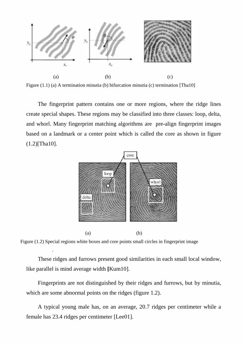
1.2 Fingerprint Concept
Fingerprints are the most important part in biometric for human identification.
They are unique and stable from birth to death. So, fingerprints have been used for
the forensic application and personal identification. Fingerprint has some unique
points on the ridge which is known as minutiae point, the minutiae could be
considered two main types of points which are termination point and bifurcation
point [Bha13]. As shown in figure (1.1).
(a) (b) (c)
Figure (1.1) (a) A termination minutia (b) bifurcation minutia (c) termination [Tha10]
The fingerprint pattern contains one or more regions, where the ridge lines
create special shapes. These regions may be classified into three classes: loop, delta,
and whorl. Many fingerprint matching algorithms are pre-align fingerprint images
based on a landmark or a center point which is called the core as shown in figure
(1.2)[Tha10].
(a) (b)
Figure (1.2) Special regions white boxes and core points small circles in fingerprint image
.
These ridges and furrows present good similarities in each small local window,
like parallel is mind average width [Kum10].
Fingerprints are not distinguished by their ridges and furrows, but by minutia,
which are some abnormal points on the ridges (figure 1.2).
A typical young male has, on an average, 20.7 ridges per centimeter while a
female has 23.4 ridges per centimeter [Lee01].
1.3 Fingerprint Representation
A representation of fingerprint is classified into three parts:
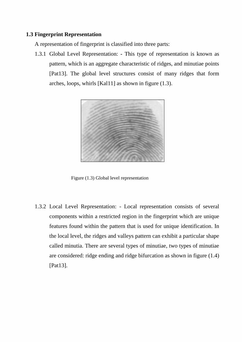
1.3.1 Global Level Representation: - This type of representation is known as
pattern, which is an aggregate characteristic of ridges, and minutiae points
[Pat13]. The global level structures consist of many ridges that form
arches, loops, whirls [Kal11] as shown in figure (1.3).
Figure (1.3) Global level representation
1.3.2 Local Level Representation: - Local representation consists of several
components within a restricted region in the fingerprint which are unique
features found within the pattern that is used for unique identification. In
the local level, the ridges and valleys pattern can exhibit a particular shape
called minutia. There are several types of minutiae, two types of minutiae
are considered: ridge ending and ridge bifurcation as shown in figure (1.4)
[Pat13].
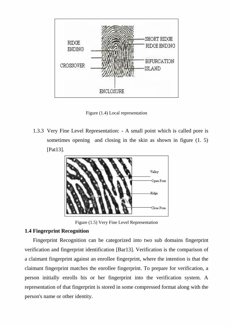
Figure (1.4) Local representation
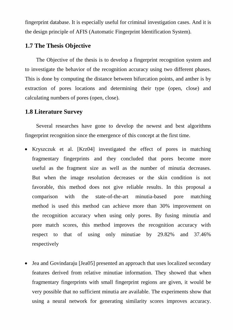
1.3.3 Very Fine Level Representation: - A small point which is called pore is
sometimes opening and closing in the skin as shown in figure (1. 5)
[Pat13].
Figure (1.5) Very Fine Level Representation
1.4 Fingerprint Recognition
Fingerprint Recognition can be categorized into two sub domains fingerprint
verification and fingerprint identification [Bar13]. Verification is the comparison of
a claimant fingerprint against an enrollee fingerprint, where the intention is that the
claimant fingerprint matches the enrollee fingerprint. To prepare for verification, a
person initially enrolls his or her fingerprint into the verification system. A
representation of that fingerprint is stored in some compressed format along with the
person's name or other identity.

Identification and verification are both used to declare the identity of a user
.Identification: In an identification system, an individual is recognized by comparing
with an entire database of templates to find a match. The system conducts one-to-
many comparisons to establish the identity of the individual. The individual to be
identified does not have to claim an identity (Who am I?) In a verification system,
the individual to be identified has to claim his/her identity (Am I whom I claim to
be?) and this template is then compared to the individual's biometric characteristic
The system conducts one-to-one comparisons to establish the identity of the
individual . Before a system is able to verify/identify the specific biometrics of a
person the system requires something to compare it with. Therefore, a profile or
template containing the biometric properties is stored in the system. Recording the
characteristics of a person is called enrollment.The processes of enrollment,
identification, and verification are depicted graphically in figure (1.6) [Sra12].

Quality checker Feature Extractor
Template name
Enrollment
Matcher (I match)Feature Extractor
verification
Claimed identity
True/False
One template
Matcher (N match)Feature Extractor
identification
N template
Users identity or “User not identity”
Figure (1.6) Enrollment, Identification and Verification system [Pro04]
Fingerprint verification is to verify the authenticity of one person by his
fingerprint. The user provides his fingerprint together with his identity information
like his ID number. The fingerprint verification system retrieves the fingerprint
template according to the ID number and matches the template with the real-time
acquired fingerprint from the user. Usually it is the underlying design principle of
AFAS (Automatic Fingerprint Authentication System). [Sin09]
Fingerprint identification is to specify one person‟s identity by his
fingerprint(s). Without knowledge of the person‟s identity, the fingerprint
identification system tries to match his fingerprint(s) with those in the whole
fingerprint database. It is especially useful for criminal investigation cases. And it is
the design principle of AFIS (Automatic Fingerprint Identification System).
1.7 The Thesis Objective
The Objective of the thesis is to develop a fingerprint recognition system and
to investigate the behavior of the recognition accuracy using two different phases.
This is done by computing the distance between bifurcation points, and anther is by
extraction of pores locations and determining their type (open, close) and
calculating numbers of pores (open, close).
1.8 Literature Survey
Several researches have gone to develop the newest and best algorithms
fingerprint recognition since the emergence of this concept at the first time.
Kryszczuk et al. [Krz04] investigated the effect of pores in matching
fragmentary fingerprints and they concluded that pores become more
useful as the fragment size as well as the number of minutia decreases.
But when the image resolution decreases or the skin condition is not
favorable, this method does not give reliable results. In this proposal a
comparison with the state-of-the-art minutia-based pore matching
method is used this method can achieve more than 30% improvement on
the recognition accuracy when using only pores. By fusing minutia and
pore match scores, this method improves the recognition accuracy with
respect to that of using only minutiae by 29.82% and 37.46%
respectively
Jea and Govindaraju [Jea05] presented an approach that uses localized secondary
features derived from relative minutiae information. They showed that when
fragmentary fingerprints with small fingerprint regions are given, it would be
very possible that no sufficient minutia are available. The experiments show that
using a neural network for generating similarity scores improves accuracy.
They've obtained 1.21% and 0.68% improvements on minimum total error rates
of different databases.
Jain et al .[Jai06] in this paper developed a matcher that utilizes Level 3 features,
including pores and ridge contours, for 1000 dpi fingerprint matching. Level 3
features are automatically extracted using wavelet transform and Gabor filters
and are locally matched using the (iteration close point) ICP algorithm.
experiments on a median-sized database show that Level 3 features carry
significant discriminatory information. EER values are reduced (relatively 20%)
when Level 3 features are employed in combination with Level 1 and 2 features
Jain et al. [Jai07] in this paper use advances in fingerprint sensing that is
technology, many sensors equipped with dual resolution (500 ppi/1000 ppi)
scanning capability. However, increasing the scan resolution alone does not
necessarily provide any performance improvement in fingerprint matching,
unless an extended feature set is utilized. As a result, a systematic study to
determine how much performance gain one can achieve by introducing level 3
features in AFIS is highly desired EER = 12% to 15% for pore matching.
Qijun et al .[qij08] in This paper explaine that real pores are not always isotropic,
To accurately and robustly extract pores, they proposed an adaptive anisotropic
pore model, whose parameters are adjusted adaptively according to the
fingerprint ridge direction and period. The fingerprint image is partitioned into
blocks and a local pore model is determined for each block. With the local pore
model, a matched filter is used to extract the pores within each block.
Experiments on a high resolution (1200dpi) fingerprint dataset were performed
and the results demonstrate that the proposed pore model and pore extraction
method can locate pores more accurately and robustly in comparison with other
state-of-the-art pore extractors. On the partial fingerprint image database, by
fusing minutia and pore match scores it improves the recognition accuracy of
using only minutiae by 34.86%
Qijun Zhao et al. [Zha09] in this paper, propose a novel direct approach for
matching fingerprint pores. It first determines the correspondences between
pores based on their local features. It then uses the RANSAC (RANdom
SAmple Consensus) algorithm to refine the pore correspondences obtained in
the first step. A similarity score is finally calculated based on the pore
matching results. The proposed pore matching method successfully avoids the
dependency of pore matching on minutia matching results. Experiments have
shown that the fingerprint recognition accuracy can be greatly improved by
using the method proposed in this paper, Recognition accuracy with respect to
that of using only minutiae is improved by 29.82% and 37.46% respectively
in terms of EER and FMR1000.
Abhyankar et al. [Abh10] in this study used fingerprint pores along the ridges
for fingerprint matching. Wavelet based fingerprint enhancement techniques
are implemented to ease detection of the level-3 features. Delaunay
triangulation based alignment and matching of the fingerprints are performed.
The pores are checked for the liveness by perspiration activity in the time
series captures. The developed matching scheme was tested for the high
resolution data (686 ppi) for 114 live and spoof fingerprint classes. ROC is
plotted and EER of 2.97% is obtained.
Nedia[Ned11] in this work, focuses on the problem of reducing the
classification fingerprint features that has been entered to the neural network.
An algorithm was introduced to work with a prepared codebook to code and
normalize the input samples of the back-propagation method. The main
advantages of preparing codebook are the simplicity of its idea and its high
speed processing. This method has been tested on the FCV2002 fingerprint
database. The recognition accuracy is 94% and the equal error rate (EER) is
2.1%.
Chandra [Cha12] in this paper uses (Scale Invariant feature transform) SIFT
algorithm. Firstly fingerprints of good quality are acquired by using optical
scanner. Image normalization is done using Gaussian blurring and sliding
window contrast adjustment. Pores are extracted and estimated. Using these
estimated pores, matching is done from template database to stored database
using SIFT algorithm. Scale Invariant Features Transform (SIFT) is an
algorithm in computer vision to detect and describe local features in images.
The features are invariant to image scaling and rotation. They are well
localized in both the spatial and frequency domains the proposed level-3
feature extraction algorithm yields a verification accuracy of 94%.
Mela [Mel13] in this work, develops a geometrically based method for
fingerprint recognition and verification tasks; a set of partial local features
extracted from fingerprint ridges, minutia, and pores attributes are used. The
proposed system passes through two main phases: training phase and test
phase. In the training phase, the system is trained using a set of low quality
fingerprint images to select the best discriminating local features this can lead
to best recognition rates. During the test phase, the system performance is
examined to know the attained recognition rate is (100%) and verification with
error rate of approximately (1.2%) at threshold value equal to (39.5). Using features
based on local ridges attributes only can lead to near optimal recognition rate of
(99.37%).
Divyaloshini V. et al [div14] in this paper presents a unique verification system
which is called fingerprint biometric authentication using Back Propagation
Neural Network method The results of authentication has been compared with
previously, implemented algorithm SVM. The mechanism has been tried with
different sets of rotation and matching, Score at the end has been computed to
93% on an average with BPNN whereas the accuracy for SVM lies in the range
from 70 to 80 %.

1.9 Thesis Organization
The remainder of the thesis is organized as follows:
Chapter 2:-"Fingerprint Recognition"
This chapter presents the background of the used biometric technologies and
techniques for Fingerprint Recognition.
Chapter 3:-" Proposed Fingerprint Recognition Model "
This chapter covers the details of the developed AFRS; their stages and
steps Also, a description for the implementation of each step is described. Also, some
examples are given to illustrate the performance of the suggested methods to handle
each system task and commonly used Algorithms in fingerprint recognition systems
are also demonstrated.
Chapter 4:- " Implementation Experimental and Results "
This chapter presents the results of experimental analysis of some tests,
Applied to define the best discriminating features, and the corresponding
Recognition performance.
Chapter 5:-"Conclusio ns and Future work"
This chapter holds a list of some conclusions after implementing the Proposed model
and it gives some suggestions for future work to enhance the presented system.
Chapter Two
Fingerprint Recognition
2.1 Introduction
Recently, forensic science has had many challenges in many different types of
crimes and crime scenes vary from physical crimes to cyber or computer crimes.
Accurate and efficient human identification or recognition have become crucial for
forensic applications due to the large diversity of crime scenes, and because of the
increasing need to accurately identify criminals from the available crime evidences.
Biometrics is an emerging technology that provides accurate and highly secure
personal identification and verification systems for civilian and forensic
applications. The positive impact of biometric modalities on forensic science began
with the rapid developments in computer science, computational intelligence, and
computing approaches. These advancements have been reflected in the biometric
modality capturing process, feature extraction, feature robustness, and features
matching. A complete and automatic biometric identification or recognition systems
have been built accordingly [Awa 14].
2.2 Biometrics Definition
Biometrics is described as the science of recognizing an individual based on his
or her physical or behavioral attributes. Biometric system broadly provides the three
functionalities such as, identification, verification, [Wab13]. Since biometric
characteristics are distinctive, and cannot be forgotten or lost, and the person to be
authenticated needs to be physically present at the point of identification, biometrics
is inherently more reliable and more capable than traditional knowledge-based and
token-based techniques. Biometrics also has a number of disadvantages. For
example, if a password or an ID card is compromised, it can be easily replaced.
However, once a biometrics is compromised, it is not possible to replace it.
Similarly, users can have a different password for each account, thus if the password
for one account is compromised, the other accounts. Are still safe, however, if a
biometrics is compromised, all biometrics-based accounts can be broken-in. Among
all biometrics (e.g., face, fingerprint, hand geometry, iris, retina, signature, voice
print, facial thermogram, hand vein, gait, ear, odor, keystroke Dynamics, etc.),
fingerprint-based identification is one of the most mature and proven technique
[Pra01].
2.3 Biometric Technology
Biometric technologies are defined as, “automated methods of verifying or
recognizing the identity of a living person based on a physiological or behavioral
characteristic”. The term “automated methods” refers to three basic methods in
concern with biometric devices [div14]:
1. A mechanism to scan and capture a digital or analog image of a living
personal characteristic;
2. Compression, processing and comparison of the image to a database of stored
images; and
3. Interface with applications systems.
2.4 Advantages of Biometrics
1. Biometric traits cannot be lost or forgotten (while passwords can).
2. Biometric traits are difficult to copy, share and distribute (passwords can be
announced in websites).
3. They require the person being authenticated to be present at the time and
point of authentication
Biometric systems of identification are enjoying a new interest. Various types of
biometric systems are being used for real-time identification. The most popular are
based on face recognition and fingerprint matching; however, other biometric
systems use iris and retinal scans, speech, facial feature comparisons and facial
thermograms, and hand geometry [div14].

2.5 A Brief Review of the Major Biometric Technologies
These technologies, fingerprint recognition, hand geometry recognition and iris
recognition are most prevalent. Having said that, considerable time and effort is
being invested in biometric technologies of the future, which include gait
recognition (the way and manner in which somebody walks), earlobe recognition
(examining the geometry of the earlobe) and DNA recognition [Rav06], (examining
the unique strands found in DNA samples). Figure (2.1) represented deferent type
of biometric technologies.
2.6 The Differences between Behavioral and Physical Biometrics
The biometric technologies fall in two categories: behavioral biometrics and
physical biometrics. In general, behavioral biometrics can be defined as the non-
biological or non- physiological features (or unique identifiers) as captured by a
biometric system. As behavioral biometrics also covers any mannerisms or behavior
displayed by an individual, this category includes signature as well as keystroke
recognition.
Physical biometrics may be defined as the biological and physiological features
(or unique identifiers) as captured by a biometric system. This category includes
fingerprint recognition, hand geometry recognition, facial recognition, iris and
retinal recognition, and voice recognition [Rav06].
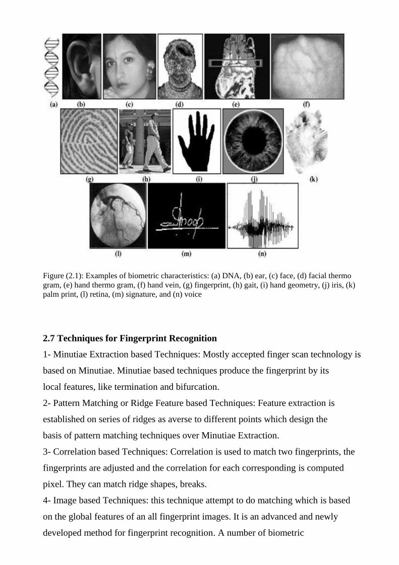
Figure (2.1): Examples of biometric characteristics: (a) DNA, (b) ear, (c) face, (d) facial thermo
gram, (e) hand thermo gram, (f) hand vein, (g) fingerprint, (h) gait, (i) hand geometry, (j) iris, (k)
palm print, (l) retina, (m) signature, and (n) voice
2.7 Techniques for Fingerprint Recognition
1- Minutiae Extraction based Techniques: Mostly accepted finger scan technology is
based on Minutiae. Minutiae based techniques produce the fingerprint by its
local features, like termination and bifurcation.
2- Pattern Matching or Ridge Feature based Techniques: Feature extraction is
established on series of ridges as averse to different points which design the
basis of pattern matching techniques over Minutiae Extraction.
3- Correlation based Techniques: Correlation is used to match two fingerprints, the
fingerprints are adjusted and the correlation for each corresponding is computed
pixel. They can match ridge shapes, breaks.
4- Image based Techniques: this technique attempt to do matching which is based
on the global features of an all fingerprint images. It is an advanced and newly
developed method for fingerprint recognition. A number of biometric
characteristics are being used in various applications because of their
universality, uniqueness, permanence, measurable [Bha13].
2.8 Classification of Fingerprints
Fingerprints are classified into three different levels: First level detail, second
level detail and third level detail.
2.8.1 First Level
The need to classify fingerprints arose when large collections of fingerprints
were to be stored in a suitable manner. As the fingerprints form definite patterns
which may resemble in overall shape and design, they can be classified and this fact
led Sir Edward Henry [Che07] to devise a classification system which is still in use
today by the name of Henry‟s Classification System. Fingerprint patterns are
classified into four groups [Che07].
1. Arches: - Arches constitute 5% of total fingerprint patterns. In this pattern, ridges
enter from one side of the impression and they flow or tend to flow towards the
other side of the impression with slight rise in the center like a small hill or a tent
forming plain arches and tented arches respectively.
2. Loops: - Loops constitute 60-65% of fingerprint patterns. When one or more
ridges enter from one side of pattern, they make a recurve and exit or tend to exit
on the same side of the impression, they form loop pattern. Loop pattern is further
subdivided into radial and ulnar loop depending on the slant of the loop ridges
whether they are slant towards the ulna or radius (bones of fore-arm) i.e. little
finger or thumb.
3. Whorls: - Whorls along with composites constitute 30-35% of the total
fingerprint patterns. When ridges recurve in circular manner and at least one ridge
makes a complete circle around the point of core, they form whorl pattern.
4. Composites: - When two or more patterns (arch, loop or whorl) combine to form
a fingerprint pattern, that pattern is called as composite. The composites may be
further subdivided into Central Pocket Loops, Lateral Pocket Loops, Twinned
Loops and Accidentals.
a. Central Pocket Loop: - In this pattern, majority of ridges form loops and one
or more ridges recurve at the core to form Pocket. In this pattern like whorl, at
least one ridge makes a complete circle around the core and there are two
deltas (point nearest to the Centre of divergence of ridges). Unlike whorl, the
line joining two deltas doesn‟t touch any recurving ridge in the pattern area.
b. Lateral Pocket Loop (Double Loop): - In this pattern there are two separate
overlapping loops with separate shoulders and two deltas. The core forming
ridges of the loops open towards the same side of the deltas.
c. Twinned Loop (Double Loop): - It is the same pattern like Lateral Pocket
Loop with the difference that the core forming ridges of the loops open
towards either side of the deltas.
d. Accidental: - The pattern which is too irregular to be classified in any of the
above patterns is called Accidental pattern.
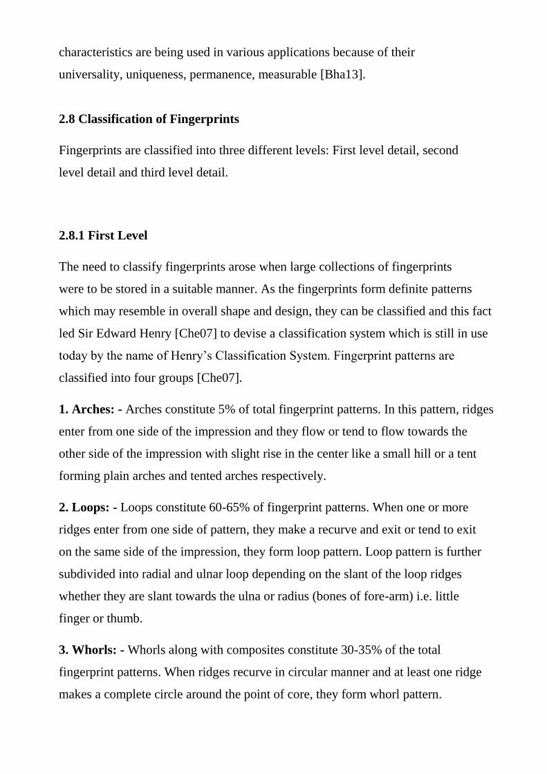
This characteristic alignment of ridges in the center of the fingerprint is known
as first level. First level detail serves as class characteristics. As shown in figure
(2.2).
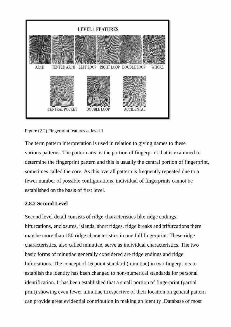
Figure (2.2) Fingerprint features at level 1
The term pattern interpretation is used in relation to giving names to these
various patterns. The pattern area is the portion of fingerprint that is examined to
determine the fingerprint pattern and this is usually the central portion of fingerprint,
sometimes called the core. As this overall pattern is frequently repeated due to a
fewer number of possible configurations, individual of fingerprints cannot be
established on the basis of first level.
2.8.2 Second Level
Second level detail consists of ridge characteristics like ridge endings,
bifurcations, enclosures, islands, short ridges, ridge breaks and trifurcations there
may be more than 150 ridge characteristics in one full fingerprint. These ridge
characteristics, also called minutiae, serve as individual characteristics. The two
basic forms of minutiae generally considered are ridge endings and ridge
bifurcations. The concept of 16 point standard (minutiae) in two fingerprints to
establish the identity has been changed to non-numerical standards for personal
identification. It has been established that a small portion of fingerprint (partial
print) showing even fewer minutiae irrespective of their location on general pattern
can provide great evidential contribution in making an identity .Database of most
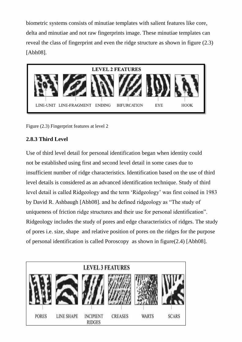
biometric systems consists of minutiae templates with salient features like core,
delta and minutiae and not raw fingerprints image. These minutiae templates can
reveal the class of fingerprint and even the ridge structure as shown in figure (2.3)
[Abh08].
Figure (2.3) Fingerprint features at level 2
2.8.3 Third Level
Use of third level detail for personal identification began when identity could
not be established using first and second level detail in some cases due to
insufficient number of ridge characteristics. Identification based on the use of third
level details is considered as an advanced identification technique. Study of third
level detail is called Ridgeology and the term „Ridgeology‟ was first coined in 1983
by David R. Ashbaugh [Abh08]. and he defined ridgeology as “The study of
uniqueness of friction ridge structures and their use for personal identification”.
Ridgeology includes the study of pores and edge characteristics of ridges. The study
of pores i.e. size, shape and relative position of pores on the ridges for the purpose
of personal identification is called Poroscopy as shown in figure(2.4) [Abh08].
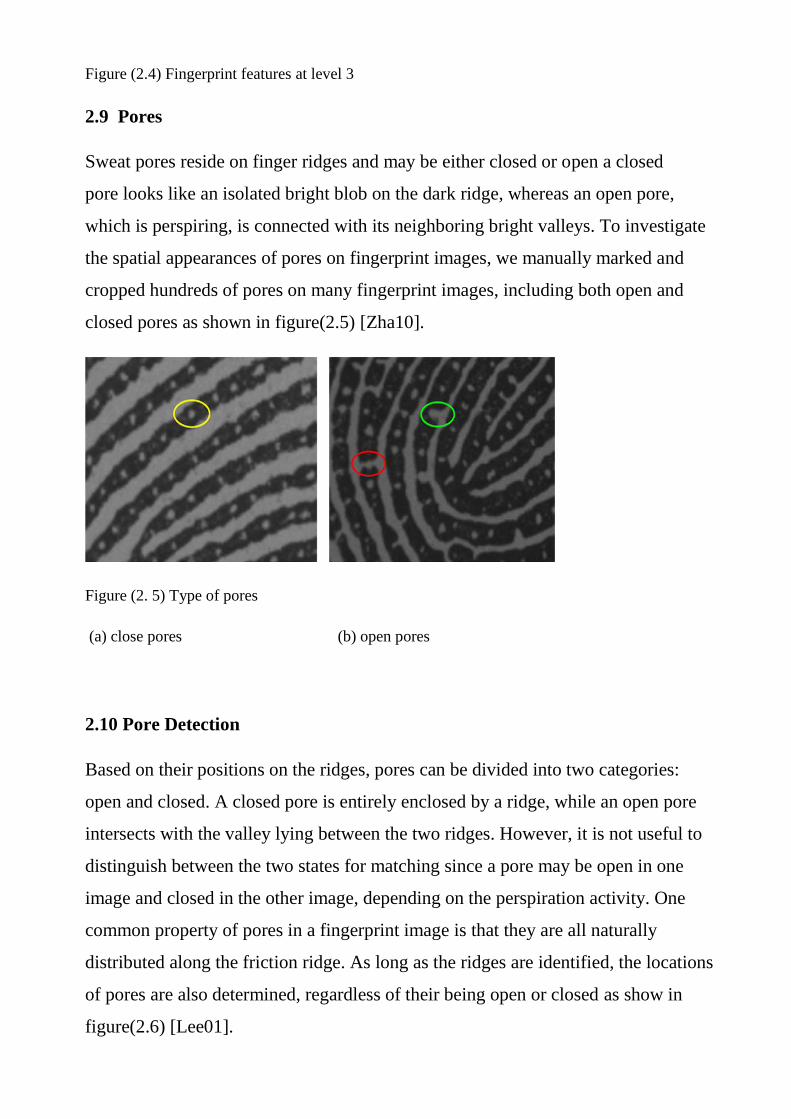
Figure (2.4) Fingerprint features at level 3
2.9 Pores
Sweat pores reside on finger ridges and may be either closed or open a closed
pore looks like an isolated bright blob on the dark ridge, whereas an open pore,
which is perspiring, is connected with its neighboring bright valleys. To investigate
the spatial appearances of pores on fingerprint images, we manually marked and
cropped hundreds of pores on many fingerprint images, including both open and
closed pores as shown in figure(2.5) [Zha10].
Figure (2. 5) Type of pores
(a) close pores (b) open pores
2.10 Pore Detection
Based on their positions on the ridges, pores can be divided into two categories:
open and closed. A closed pore is entirely enclosed by a ridge, while an open pore
intersects with the valley lying between the two ridges. However, it is not useful to
distinguish between the two states for matching since a pore may be open in one
image and closed in the other image, depending on the perspiration activity. One
common property of pores in a fingerprint image is that they are all naturally
distributed along the friction ridge. As long as the ridges are identified, the locations
of pores are also determined, regardless of their being open or closed as show in
figure(2.6) [Lee01].
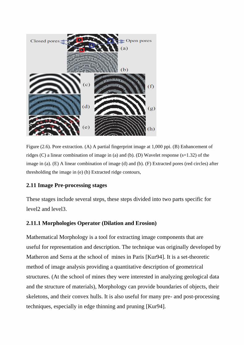
Figure (2.6). Pore extraction. (A) A partial fingerprint image at 1,000 ppi. (B) Enhancement of
ridges (C) a linear combination of image in (a) and (b). (D) Wavelet response (s=1.32) of the
image in (a). (E) A linear combination of image (d) and (b). (F) Extracted pores (red circles) after
thresholding the image in (e) (h) Extracted ridge contours,
2.11 Image Pre-processing stages
These stages include several steps, these steps divided into two parts specific for
level2 and level3.
2.11.1 Morphologies Operator (Dilation and Erosion)
Mathematical Morphology is a tool for extracting image components that are
useful for representation and description. The technique was originally developed by
Matheron and Serra at the school of mines in Paris [Kur94]. It is a set-theoretic
method of image analysis providing a quantitative description of geometrical
structures. (At the school of mines they were interested in analyzing geological data
and the structure of materials), Morphology can provide boundaries of objects, their
skeletons, and their convex hulls. It is also useful for many pre- and post-processing
techniques, especially in edge thinning and pruning [Kur94].

Generally speaking most morphological operations are based on simple
expanding and shrinking operations. The primary application of morphology occurs
in binary images, though it is also used on grey level images. It can also be useful on
range images.
The two basic morphological sets of transformations are erosion and dilation
these transformations involve the interaction between an image A (the object of
interest) and a structuring element B, called the structuring element.
Typically the structuring element B is a circular disc in the plane, but it can be
any shape. The image and structuring element sets need not be restricted to sets in
the 2D plane.
Let A and B be subsets of Z2. The translation of A by x is denoted Ax and is
defined as
Ax={c: c = a +x, for a A} (2.1)
The complement of A is denoted Ac, and the difference of two sets A and B
is denoted A - B.
The reflection of B, denoted, is defined as
B={x: x = -b, for b ∈B} (2.2)
These are the basic operations of morphology, in the sense that all other
operations are built from a combination of these two.
2.11.2 Dilation
Suppose A and B are sets of pixels. Then the dilation of A by B,
denoted , is defined as

What this means is that for every point , is translated A by those
coordinates. Then take the union of all these translations.
An equivalent definition is that
From this last definition, dilation is shown to be commutative; that
An example of dilation is given in figure (2.7). In the translation diagrams, the grey
squares show the original position of the object. Note that A (0,0) is of course just A
itself. In this example, have
and those are the coordinates by which translated A.
In general, can be obtained by replacing every point (x,y) in A with a
copy of B, placing the (0,0) point of B at (x,y). Equivalently, could replace very
point (u, v) of B with a copy of A.
Dilation is also known as Murkowski addition; see Haralick and Shapiro
[Rod97] for more information. As you see in figure (2.7), dilation has the effect of
increasing the size of an object. However, it is not necessarily true that the original
object A will lie within its dilation . Depending on the coordinates of B,
may end up quite a long way from which A is the same as in figure (2.8) B
has the same shape but a different position. In figure (2.7),
So that,
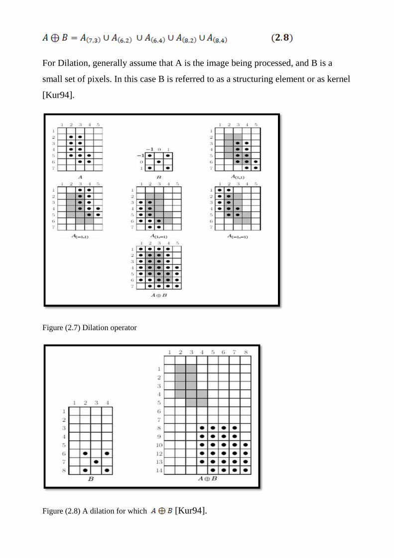
For Dilation, generally assume that A is the image being processed, and B is a
small set of pixels. In this case B is referred to as a structuring element or as kernel
[Kur94].
Figure (2.7) Dilation operator
Figure (2.8) A dilation for which [Kur94].

2.11.3 Erosion
Given sets A and B, the erosion of A by B, written , is defined as
In other words the erosion of A by B consists of all points w=(x,y) for which Bw
is in A. To perform an erosion, then moved B over A, and find all the places it will
fit, and for each such place mark down the corresponding (0,0) point of B. the set of
all such points will form the erosion. An example of erosion is given in figure (2.9).
Note that in the example, the erosion is a subset of A. This is not
necessarily the case; in depends on the position of the origin in B. if B contains the
origin, then the erosion will be a subset of the original object. As shown in Figure
(2.9) .
Figure (2.9) Applying dilation operator and erosion to binary image
For erosion, as for dilation, generally assume that A is the image being
processed, and B is a small set of pixels: the structuring element or kernel.
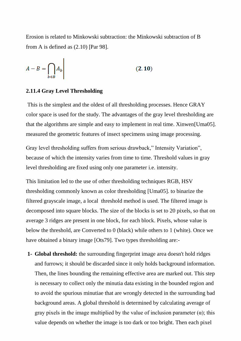
Erosion is related to Minkowski subtraction: the Minkowski subtraction of B
from A is defined as (2.10) [Par 98].
2.11.4 Gray Level Thresholding
This is the simplest and the oldest of all thresholding processes. Hence GRAY
color space is used for the study. The advantages of the gray level thresholding are
that the algorithms are simple and easy to implement in real time. Xinwen[Uma05].
measured the geometric features of insect specimens using image processing.
Gray level thresholding suffers from serious drawback,” Intensity Variation”,
because of which the intensity varies from time to time. Threshold values in gray
level thresholding are fixed using only one parameter i.e. intensity.
This limitation led to the use of other thresholding techniques RGB, HSV
thresholding commonly known as color thresholding [Uma05]. to binarize the
filtered grayscale image, a local threshold method is used. The filtered image is
decomposed into square blocks. The size of the blocks is set to 20 pixels, so that on
average 3 ridges are present in one block, for each block. Pixels, whose value is
below the threshold, are Converted to 0 (black) while others to 1 (white). Once we
have obtained a binary image [Ots79]. Two types thresholding are:-
1- Global threshold: the surrounding fingerprint image area doesn't hold ridges
and furrows; it should be discarded since it only holds background information.
Then, the lines bounding the remaining effective area are marked out. This step
is necessary to collect only the minutia data existing in the bounded region and
to avoid the spurious minutiae that are wrongly detected in the surrounding bad
background areas. A global threshold is determined by calculating average of
gray pixels in the image multiplied by the value of inclusion parameter (α); this
value depends on whether the image is too dark or too bright. Then each pixel

value in the image smaller than the threshold will set 0, otherwise its gray value
is kept without any change.
2- Local thresholding: method is adopted; it is based on the local characteristics
of fingerprint image. The threshold assessment process is started with
calculating the average intensity value in a large block surrounding certain area
of the image Then, all the pixels which belong to a small block which lie within
the central area of the large block are binarized by comparing its value with the
determined threshold value to decide whether each pixel belong to ridge or
background [Mel13].
2.11.5 Thinning Process
The Zhang-Suen algorithm (ZS algorithm) is a Fast Parallel Algorithm for
Thinning Digital Patterns. A 3x3 window is moved down throughout the image and
calculations are carried out on each ridge pixel, which has the value "1" and black
color, to decide whether it needs to stay in the image or not. The iteration from one
pixel to another used in this algorithm is clockwise [Ack08].
A. Odd sub-iteration flag a point P1 for deletion if all the following conditions
are satisfied:
a. Count with connectivity 1.
A (P1) = 1
b. Have a number of nonzero black neighbors, B(P1), between 2 and 6
2≤ B (P1) ≤ 6
c. Have at least one of the following pixels in zero white: [x-1, y],
[x, y+1], [x+1, y]]
P2 * P4 * P6 = 0
d. Have at least one of the following pixels in zero white [x-1, y],
[x+1, y] y], [x, y-1]

P4 * P6 * P8 = 0
where A (P1) is total occurrences of 0-1 patterns (current pixel value 0 and next
pixel value 1) in the ordered sequence P2, P3, P4, P5, P6, P7, P8, and P9, the "*"
expresses logic "AND" operation, and the B(P1) function returns the number of
nonzero black pixels in the structuring element.
B (P1) = P2 + P3 + P4 + P5 + P6 + P7 + P8 + P9
For example:
B (P1) = 0 + 1 + 1 + 0 + 0 + 0 + 1 + 0
B (P1) = 3, and A (P1) =2.
B. In even sub-iteration, only the condition items c. & d. in the first iteration are
replaced, the following conditions would be applied:
a. Count with connectivity 1.
A (P1) = 1
b. Have a quantity of nonzero black neighbors between 2 and 6
(Included).
2≤ B (P1) ≤ 6
c. Have at least one of the following pixels in white: [x-1,y], [x,y+1],
[x,y- 1]
P2 * P4 * P8 = 0
d. Have at least one of the following pixels in white: [x,y+1], [x+1,y],
[x, y-1]
P2 * P6 * P8 = 0
As previously expressed, iterations will go on as points are being eliminated
(changed to zero) [Dav13].
2.11.6 Image Smoothing
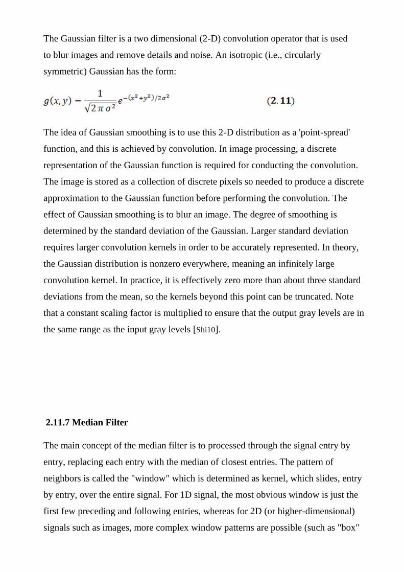
The Gaussian filter is a two dimensional (2-D) convolution operator that is used
to blur images and remove details and noise. An isotropic (i.e., circularly
symmetric) Gaussian has the form:
The idea of Gaussian smoothing is to use this 2-D distribution as a 'point-spread'
function, and this is achieved by convolution. In image processing, a discrete
representation of the Gaussian function is required for conducting the convolution.
The image is stored as a collection of discrete pixels so needed to produce a discrete
approximation to the Gaussian function before performing the convolution. The
effect of Gaussian smoothing is to blur an image. The degree of smoothing is
determined by the standard deviation of the Gaussian. Larger standard deviation
requires larger convolution kernels in order to be accurately represented. In theory,
the Gaussian distribution is nonzero everywhere, meaning an infinitely large
convolution kernel. In practice, it is effectively zero more than about three standard
deviations from the mean, so the kernels beyond this point can be truncated. Note
that a constant scaling factor is multiplied to ensure that the output gray levels are in
the same range as the input gray levels [Shi10].
2.11.7 Median Filter
The main concept of the median filter is to processed through the signal entry by
entry, replacing each entry with the median of closest entries. The pattern of
neighbors is called the "window" which is determined as kernel, which slides, entry
by entry, over the entire signal. For 1D signal, the most obvious window is just the
first few preceding and following entries, whereas for 2D (or higher-dimensional)
signals such as images, more complex window patterns are possible (such as "box"
or "cross" patterns). Note that if the window has an odd number of entries, then the
median is simple to define: it is just the middle value after all the entries in the
window are sorted numerically. For an even number of entries, there is more than
one possible median, see median for more details [Ari09]. The median filter is a
nonlinear filter, which can reduce impulsive distortions in an image and without too
much distortion to the edges of such an image. It is an effective method that of
suppressing isolated noise without blurring sharp edges [Aib06].
2.12 ICP Algorithm
ICP (Iterative Closest Point) algorithm is widely used for geometric alignment
of three-dimensional models when an initial estimate of the relative pose is known.
Many variants of ICP have been proposed, affecting all phases of the algorithm
from the selection and matching of points to the minimization strategy, Enumerating
and classifying many of these variants, and evaluating their effect on the speed with
which the correct alignment is reached. In order to improve convergence for nearly-
flat meshes with small features, such as inscribed surfaces, a new variant is
introduced based on uniform sampling of the space of normal, concluded by
proposing a combination of ICP variants optimized for high speed, demonstrated an
implementation that is able to align two range images in a few tens of milliseconds,
assuming a good initial guess. This capability has potential application to real-time
3D model acquisition and model-based tracking [Szy01], The Iterative Closest Point
Algorithm has become established as one the most useful methods of range data.
Processing given two sets of partially overlapping range data and an initial
estimate of their relative positions, ICP is used to register the data sets by improving
the position and orientation estimate. ICP is an essential step in model building,
dimensional inspection, and numerous applications of range data processing. At
each ICP iteration, correspondences are determined between the two data sets, and a
transformation computed which minimizes the mean square error (MSE) of the
correspondences. The iterations continue until either the (MSE) falls below some
threshold values, the maximum number of iterations is exceeded, or some other
stopping condition is satisfied, due to its fairly large computational expense,
ICP is typically considered to be a batch or, at best, a user-guided online process
where the user initiates and assists the process and then allows it to execute
unsupervised for a number of minutes. An ICP which executes in real-time, or near
real-time, would prove advantageous in several situations. One reason is that range
data acquisition sensors are getting faster. The combination of real time range data
acquisition with a real-time ICP forms the basis of a number of new and useful
systems, such as geometric tracking and hand-held sensors. Furthermore, there are
emerging applications such as environment modeling where the volume of data is
large, and for which any improvement in the speed of ICP is desirable. There has
been some previous work in developing efficient versions of ICP. Implemented
efficient correspondence calculations based upon the k-d tree and decoupled
acceleration for the rotation and translation components. Implemented and
compared a variety of model representations and correspondence methods proposed
a correspondence method which is specifically tailored to efficient ICP. A generic
method for speeding up computations is parallelization. [Lan01].
2.12.1 Selection of Points
The effect of the selection of point pairs on the convergence of ICP was
examined. The following strategies have been proposed:
Always use all available points.
Uniform subsample the available points.
Random sample (with a different sample of points at each iteration).
Select points with high intensity gradient, in variants that use per-sample
color or intensity to aid in alignment [Szy01].
2.12.2 Euclidean Distance Equation
Euclidean distance is the distance between two points in Euclidean space.
Euclidean space was originally devised by the Greek mathematician Euclid around
300 B.C.E. to study the relationships between angles and distances. This system of

geometry is still in use today and is the one that high school students study most
often. Euclidean geometry specifically applies to spaces of two and three
dimensions. However, it can easily be generalized to higher order dimensions.
calculate the If the coordinates of the points (x, y) are given then we can
distance using the formula,
d = √ ((x2 – x1)2 + (y2 – y1)
2) (2.12)
Where x1 and y1 are the coordinates of one point and x2, y2 are coordinates of
another point, and d is called the distance between the two points. The distance
gives the numerical illustration of the location of the objects. Here we will see about
the Euclidean equation to measure the distance.

Proposed Fingerprint Recognition System
(PFR)
3.1 Introduction
This chapter is devoted to present the design considerations, design
requirements and the steps taken throughout the establishment of the proposed PFR
system. The design steps are illustrated in detail.
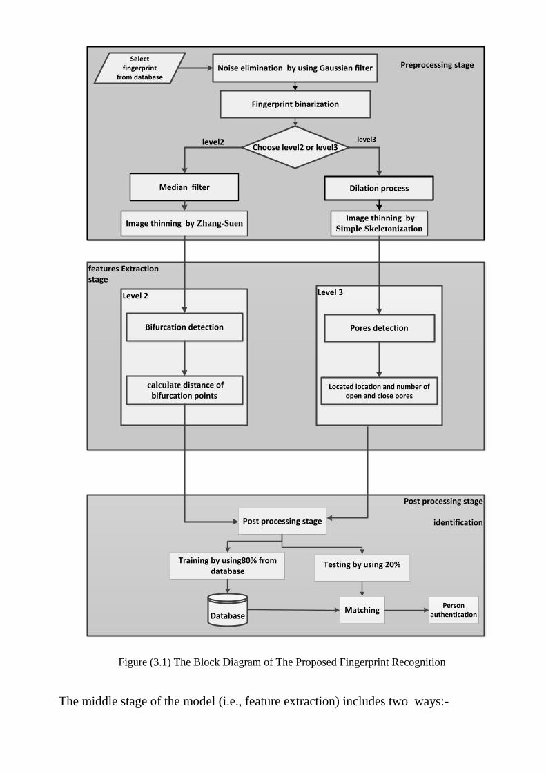
The implemented PFR consists of three major stages: preprocessing, feature
extraction, and post-processing. These three stages are executed sequentially. Figure
(3.1) shows the main architecture of the proposed PFR system.
The preprocessing stage is considered as a necessary step in the reliable system
since extraction and matching stages depend greatly upon the quality of the input
fingerprint image. Therefore a preprocessing should cover four main steps.
The preprocessing is image noise elimination, the system used Gaussian filter
for removing the image noise. A global binarization is applied on the gray level
image; that is based on the minimum and maximum contrast.
Two approaches are used to process fingerprint image, level2 and level3. In
level2 extracting bifurcation points and distances between the are calculated, while
in level3 morphological operating (dilation and erosion) and pores features when
extracted.
features Extraction stage
level2
Select fingerprint
from databaseNoise elimination by using Gaussian filter
Fingerprint binarization
Dilation process
Preprocessing stage
Post processing stage
identification
Image thinning by Simple Skeletonization
Image thinning by Zhang-Suen
Database
Level 2
Bifurcation detection
calculate distance of bifurcation points
Level 3
Pores detection
Located location and number of open and close pores
Median filter
Choose level2 or level3level2 level3
Person authentication
Post processing stage
Training by using80% from database
Testing by using 20%
Matching
Figure (3.1) The Block Diagram of The Proposed Fingerprint Recognition
The middle stage of the model (i.e., feature extraction) includes two ways:-

a- Extract bifurcation points (level2) and calculate the distance among these
bifurcation points.
b- Locate pores' positions (level3) and calculate the number of open and
closed pores.
In the post-processing stage, bifurcation points were extracted and the distances
between them were calculated. Also the numbers of open and closed pores were
collected. These features matched with previous extracted vectors which listed in
fingerprints database for recognition and identification purpose.
3.2 Preprocessing
The first phase which has been analyzed using various image preprocessing
stages is shown in figure (3.1). Each step of this phase has been described in detail.
3.2.1 Select Fingerprint Image
The fingerprint image is served to the model as a (JPEG) image file. The image
data is loaded from the database as a gray image.
3.2.2 Noise Removal
The most common method used to reduce the existing noise in the image is
Gaussian filtering method with a mask size of (5x5) With the use of filter (5x5 ) as a
result of the experiences attempted, algorithm (3.1) presents the implemented steps
for Gaussian filter.
Algorithm Gaussian filter (3.1)
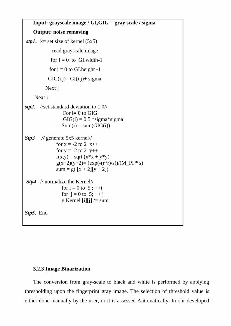
Input: grayscale image / GI,GIG = gray scale / sigma
Output: noise removing
stp1. k= set size of kernel (5x5)
read grayscale image
for I = 0 to GI.width-1
for j = 0 to GI.height -1
GIG(i,j)= GI(i,j)+ sigma
Next j
Next i
stp2. //set standard deviation to 1.0//
For i= 0 to GIG
GIG(i) = 0.5 *sigma*sigma
Sum(i) = sum(GIG(i))
Stp3 // generate 5x5 kernel//
for x = -2 to 2 x++
for y = -2 to 2 y++
r(x,y) = sqrt (x*x + y*y(
g(x+2)(y+2)= (exp(-(r*r)/s))/(M_PI * s)
sum = g( [x + 2][y + 2])
Stp4 // normalize the Kernel//
for i = 0 to 5 ; ++i
for j = 0 to 5; ++ j
g Kernel [i][j] /= sum
Stp5. End
3.2.3 Image Binarization
The conversion from gray-scale to black and white is performed by applying
thresholding upon the fingerprint gray image. The selection of threshold value is
either done manually by the user, or it is assessed Automatically. In our developed

system the proper value of threshold is estimated automatically. Also, the global
thresholding method is adopted; it is based on the local characteristics of fingerprint
image. The threshold assessment process is started with calculating the average
intensity value in a large block surrounding certain area of the image, this value is
used as a global threshold value. As shown in algorithm (3.2).
Algorithm Binarization process (3.2)
Inputs: Gray() // array of Gray pixels values
Hgt // the height of the Image
Wid // the width of the Image
Output: Glo() // the array to convert from gray image to binary
Stp1 : Initialize minimum (Min) and Max values
Min ←Gray(0, 0); Max← Gray(0, 0);
Stp2 : Compare each pixel with Min and Max
all pixels in the image // x as row number, y as column number//
If Gray(x, y) < Min Then
Min← Gray(x, y)
End If
If Gray(x, y) > Max Then
Max← Gray(x, y)
End If
End For // x & y
Stp3 : Thr ← (Min + Max) / 2 // Calculate threshold//
Stp4 : For all pixel in the image // x as row number, y as column number //
If Gray(x, y) ≥ Thr Then
Glo(x, y) ← 1
Else
Glo(x, y) ← 0
End If
End For
Stp5 : END
3.3 Feature Extraction
In this stage, a set of features is extracted. So, an array of values for each
feature over the whole image is obtained. Generally, this process includes extracting
features from levels two and three.
3.3.1 Select Level2 Features
The distance between bifurcation points is extracted, this process is done using
two steps:
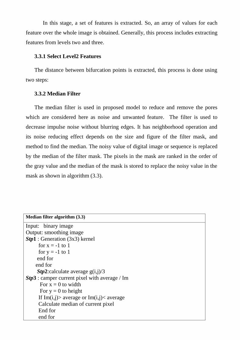
3.3.2 Median Filter
The median filter is used in proposed model to reduce and remove the pores
which are considered here as noise and unwanted feature. The filter is used to
decrease impulse noise without blurring edges. It has neighborhood operation and
its noise reducing effect depends on the size and figure of the filter mask, and
method to find the median. The noisy value of digital image or sequence is replaced
by the median of the filter mask. The pixels in the mask are ranked in the order of
the gray value and the median of the mask is stored to replace the noisy value in the
mask as shown in algorithm (3.3).
Median filter algorithm (3.3)
Input: binary image
Output: smoothing image
Stp1 : Generation (3x3) kernel
for x = -1 to 1
for y = -1 to 1
end for
end for
Stp2:calculate average g(i,j)/3
Stp3 : camper current pixel with average / Im
For x = 0 to width
For y = 0 to height
If Im(i,j)> average or Im(i,j)< average
Calculate median of current pixel
End for
end for

end for
Stp4: End
I. zhang-suen Process
PFR model used a compact representation called skeleton that is played in detail
in (2.8.5, Thinning Process) in order to complete faster processing and smaller
memory fingerprint. A thinning must preserve the structure of the shape but all
redundant pixels should be removed. Algorithm (3.5) shows a thinning process.
Algorithm of thinning (3.5)
Input: binary image
Output: skeletonized image
Stp1. a [8]= kernel 3x3
Stp2. For image height and width do
ar= image data (0 and 1)
p1 = a [0] * a[2] * a[6]
p2 = a [0] * a[4] * a[6]
b = number of 1's in current window (mask)
Stp3. If ar=1 and b>=2 and b<=6 and p1=0 and p2=0
Y =1
Else y =0
Stp4. Set y to new image
Stp5. End
I. Bifurcation Points Extraction
Bifurcations are points at which a single ridge splits into two ridges. A(3x3)
mask is used to search the bifurcation points in a fingerprint image as described in
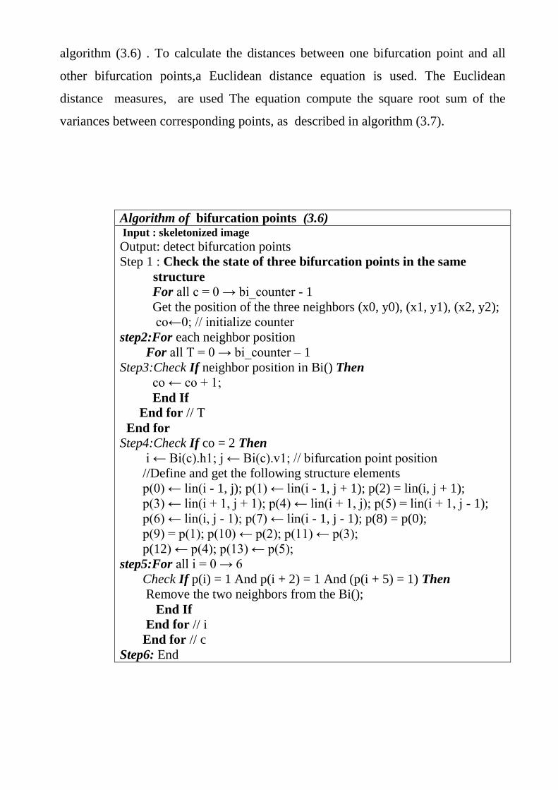
algorithm (3.6) . To calculate the distances between one bifurcation point and all
other bifurcation points,a Euclidean distance equation is used. The Euclidean
distance measures, are used The equation compute the square root sum of the
variances between corresponding points, as described in algorithm (3.7).
Algorithm of bifurcation points (3.6) Input : skeletonized image Output: detect bifurcation points
Step 1 : Check the state of three bifurcation points in the same
structure
For all c = 0 → bi_counter - 1
Get the position of the three neighbors (x0, y0), (x1, y1), (x2, y2);
co←0; // initialize counter
step2:For each neighbor position
For all T = 0 → bi_counter – 1
Step3:Check If neighbor position in Bi() Then
co ← co + 1;
End If
End for // T
End for
Step4:Check If co = 2 Then
i ← Bi(c).h1; j ← Bi(c).v1; // bifurcation point position
//Define and get the following structure elements
p(0) ← lin(i - 1, j); p(1) ← lin(i - 1, j + 1); p(2) = lin(i, j + 1);
p(3) ← lin(i + 1, j + 1); p(4) ← lin(i + 1, j); p(5) = lin(i + 1, j - 1);
p(6) ← lin(i, j - 1); p(7) ← lin(i - 1, j - 1); p(8) = p(0);
p(9) = p(1); p(10) ← p(2); p(11) ← p(3);
p(12) ← p(4); p(13) ← p(5);
step5:For all i = 0 → 6
Check If p(i) = 1 And p(i + 2) = 1 And (p(i + 5) = 1) Then
Remove the two neighbors from the Bi();
End If
End for // i
End for // c Step6: End

Algorithm of Euclidean distance (3.7)
Input: N: number of bifurcation points
Output: Distance between bifurcation points
Stp1. Given vector x1 and y1,each vector is coordinate in n
dimension
Dist array of (x,y)
Dist =0
Stp2. For d = 1 to n // d= dimension
Dist[d] = Dist[d] + (x1[d]ᴧ2
– x2[d]ᴧ2
)+ (y1[d]ᴧ2
– y2[d])ᴧ2
)
Next
end for
Stp3. Return sqrt (Dist)
Stp4. End
III. Matching level2
Iterative Closest Point (ICP) is an algorithm working to minimize the
difference between two closets of points. ICP is regularly used to re-form 2D or 3D
surfaces from variance scans, to limit automatons and achieve optimal path.
The reference, or aim, is kept fixed, while the other one, the source, is
transformed to best competition the reference. The algorithm iteratively rereads the
alteration (combination of translation and rotation) needed to minimize the distance
from the source to the reference points as shown in algorithm (3.8).
3.3.3 Select Level3 Features
Extraction level3 (extraction level3 features) is done by two steps followed by
post processing stage. These features discussed as below:
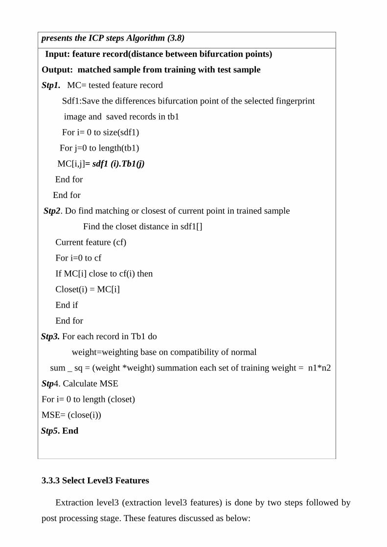
presents the ICP steps Algorithm (3.8)
Input: feature record(distance between bifurcation points)
Output: matched sample from training with test sample
Stp1. MC= tested feature record
Sdf1:Save the differences bifurcation point of the selected fingerprint
image and saved records in tb1
For i= 0 to size(sdf1)
For j=0 to length(tb1)
MC[i,j]= sdf1 (i).Tb1(j)
End for
End for
Stp2. Do find matching or closest of current point in trained sample
Find the closet distance in sdf1[]
Current feature (cf)
For i=0 to cf
If MC[i] close to cf(i) then
Closet(i) = MC[i]
End if
End for
Stp3. For each record in Tb1 do
weight=weighting base on compatibility of normal
sum _ sq = (weight *weight) summation each set of training weight = n1*n2
Stp4. Calculate MSE
For i= 0 to length (closet)
MSE= (close(i))
Stp5. End

3.3.6 Morphological operation
Dilation and erosion are approach an the preprocessed image.
I. Image Dilation Process
The dilation process is performed by laying the window on the image and
sliding it across the image, is used to thicken the edges in order to eliminate weak
pores as shown in algorithm (3.9).
II. Image Erosion Process
The erosion process is similar to dilation, but turns pixels to 'white', not 'black as
shown in algorithm (3.10).
Erosion process Algorithm (3.10)
Input: Dilated Image
Output: Shrink edges in the Image
stp1. Set a window (3x3)
stp2. For all pixels in the image
For all pixels within the mask
dilation process Algorithm (3.9)
Input: Binarized Image
Output: Dilated Image
Stp1. Set a mask (3x3)
Stp2. For all pixels in the image
For all pixels within the mask
If any pixel within the mask = 0 then
Convert each pixel in the image within the window to
black End If
End For
End For
Stp3 : END

If any pixel within the mask= 1 then
Convert each pixel in the image within the window to
white
End If
End For
End For
Stp3: END
III. Detecting The Pores
The proposed model detects the pore's location in all ridges within the selected
area.
IV. Number of Pores
The pores divided into two types, closed and open. This step calculates number of
open and close pores within the selected area suppose that the number of pixels the
Surrounding of the pixel is10 points one as shown in algorithm (3.11).

pores detection Algorithm (3.11)
Input: skeleton image
Output: pores detection (closed and opened) number
Stp1 all pixels in the image (within the selected window)
Stp2. R = find ridge and put in array
For each point in R
Determine it's (x, y) coordinate
P number of pixels in the ridge
Stp3. If P < 10 then
Specify selected pores as open pore
Else
Specify it as close pore
End If
Stp4. END
3.4 Matching level3
The closest algorithm has been used during matching phase to find the best
matched of pores points and the feature pores points has depend on the location of
these points (x and y) and number of pores as shown in algorithm(3.12) .

Closest point Algorithm (3.12)
Input: pores positions
Output: array of closest points
Stp1: initialization variables
X, y :first point coordinate x-axis and y-axis
Stp2: search closest
for each p : (x1,y1) in array
if first Point < p
first Point = p
Dist[]=sqrt ((x2 – x1)^2 + (y2 – y1)^
2 (
else
First Point = first Point
Stp3: return
Dist[] contains all closest for each point with others
Stp4: End
Chapter Four
Implementation Experimental and Results
4.1 Introduction
In this chapter, the results of some conducted tests are presented. A set of tests
has been conducted in order to evaluate the performance of the established
fingerprint verification system. Also, the results of the stage which was conducted to
assess the discrimination capabilities of the extracted fingerprint features are
illustrated. The developed system has been established using Microsoft Visual
Studio (version 2010) programming language C#, and the tests have been conducted
under the environment: Windows-7 operating system, laptop computer (processor:
Intel(R) Core i5 CPU 1.60 GHz, and (8.00 GB) RAM.
The system focuses on analyzing pores number with their positions and
distance between bifurcation points in a fingerprint image, several methods have
been applied during the programming and testing the proposed system.
The fingerprint images are adopted from database names (sample fingerprint)
loaded from (biometrics ideal test) web a JPEG 24 bit/pixel (bit depth), the size of
each used image is 360×480 pixels with resolution 96 dpi. The number of
fingerprint samples is for 100 people, 10 image for each person (i.e. 1000 sample
were taken) are of different contrast (dark and light) and moves are belong to a
specific person. Eight images are taken as training images and two are taken as
testing images.
Two options were adopted in the proposed system; the first one is to find
bifurcation points and their distance while the second stage is to find number of
pores and their types. The elapse time has been calculated during the stages of the
system process to evaluate the proposed system.
4.2 Preprocessing Stage
Fingerprint image enhancement is used to create the image clearer for easy
advanced operations. Since the fingerprint images in the used data base attained

from scanner or any other media are not assured with perfect quality, therefore
enhancement methods are need .For increasing the contrast between ridges, valleys,
and pores. This phase consists of three steps as shown.
4.2.1 Noise Removal
In the preprocessing phase, the Gaussian filter is used to smooth the image and
to eliminate the Gaussian noises.
The process of Gaussian filter is done by convolving each point in the input image
(browsed image) with a Gaussian mask (5x5) the mask size filter(3x3) and (7x7)
gave undesired result . and then summing them all to produce the output image,
Besides applied Gaussian filter with different rates of sigma and during, our
experimental work it is noted that the best sigma is (0.5) as shown in figure (4.1).
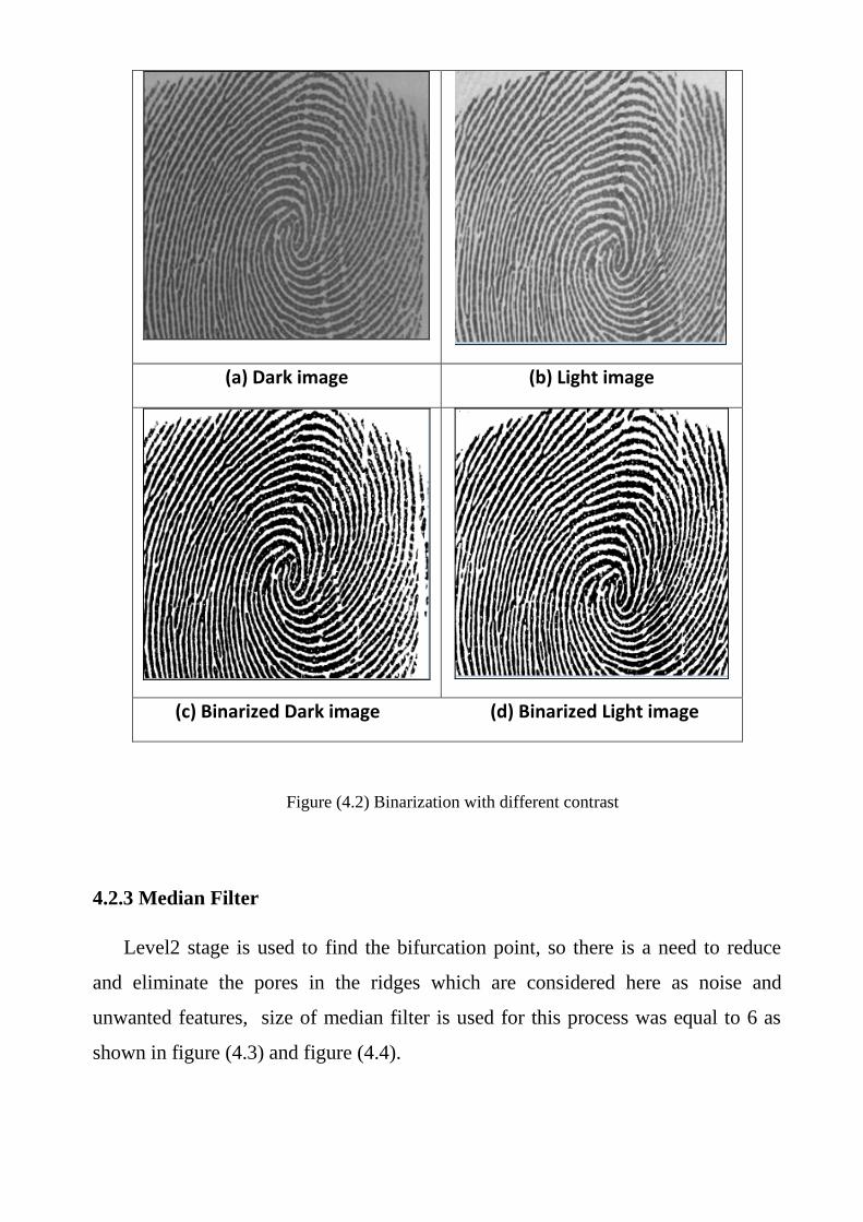
4.2.2 Image Binarization
The fingerprints in the database are all gray images. A global threshold is
determined. The threshold value depends on brightness of the image. Then each
pixel is smaller than the threshold will be set to zero, otherwise will set to 1 figure
(4.2) shows it all
The purpose of binarization is to extract the pixels from image which represent
an object.
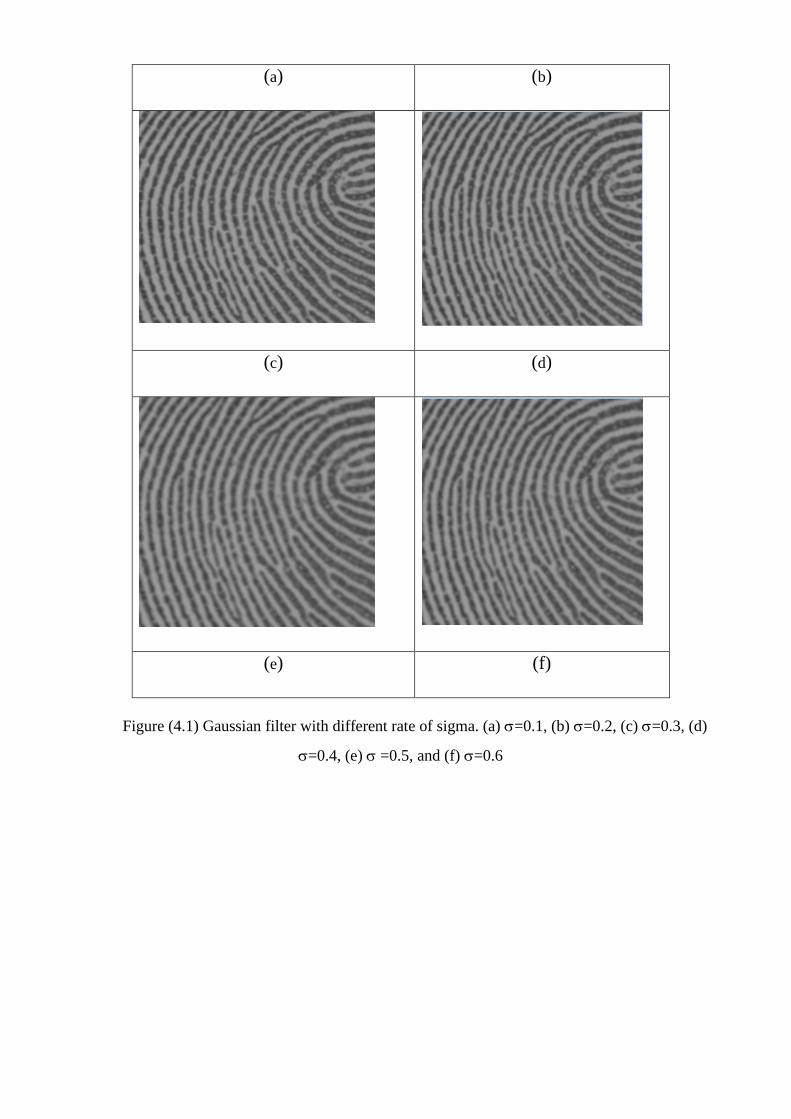
Figure (4.1) Gaussian filter with different rate of sigma. (a) =0.1, (b) =0.2, (c) =0.3, (d)
=0.4, (e) =0.5, and (f) =0.6
(a) (b)
(c) (d)
(e) (f)
(b) Light image (a) Dark image
(c) Binarized Dark image (d) Binarized Light image
Figure (4.2) Binarization with different contrast
4.2.3 Median Filter
Level2 stage is used to find the bifurcation point, so there is a need to reduce
and eliminate the pores in the ridges which are considered here as noise and
unwanted features, size of median filter is used for this process was equal to 6 as
shown in figure (4.3) and figure (4.4).
Before After
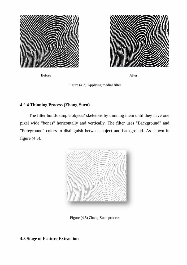
Figure (4.3) Applying medial filter
4.2.4 Thinning Process (Zhang-Suen)
The filter builds simple objects' skeletons by thinning them until they have one
pixel wide "bones" horizontally and vertically. The filter uses "Background" and
"Foreground" colors to distinguish between object and background. As shown in
figure (4.5).
Figure (4.5) Zhang-Suen process
4.3 Stage of Feature Extraction
The proposed methods implemented to perform fingerprint feature extraction
from two levels (level 2 and level 3) have been discussed follows.
4.3.1 Level2 Features Extraction
To extract level2 features, the implemented method is based on following
criteria:
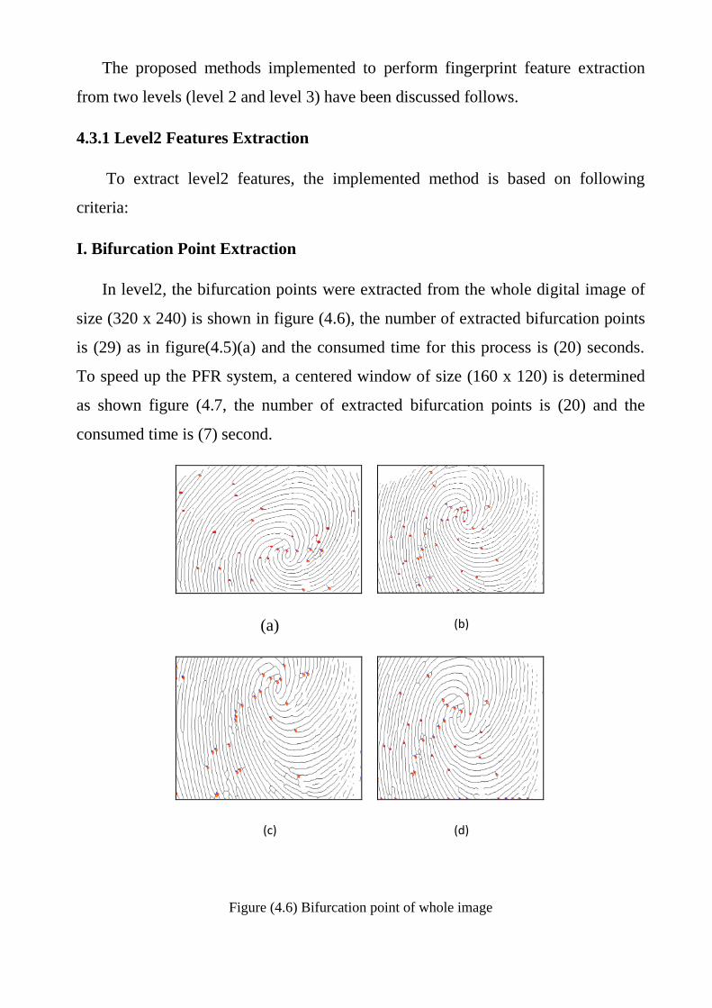
I. Bifurcation Point Extraction
In level2, the bifurcation points were extracted from the whole digital image of
size (320 x 240) is shown in figure (4.6), the number of extracted bifurcation points
is (29) as in figure(4.5)(a) and the consumed time for this process is (20) seconds.
To speed up the PFR system, a centered window of size (160 x 120) is determined
as shown figure (4.7, the number of extracted bifurcation points is (20) and the
consumed time is (7) second.
(a) (b)
(c) (d)
Figure (4.6) Bifurcation point of whole image

Figure (4.7) Bifurcation point within the selected window
Figure (4.8) shows different detected number of bifurcation points on the same
person on different contrast and moves.
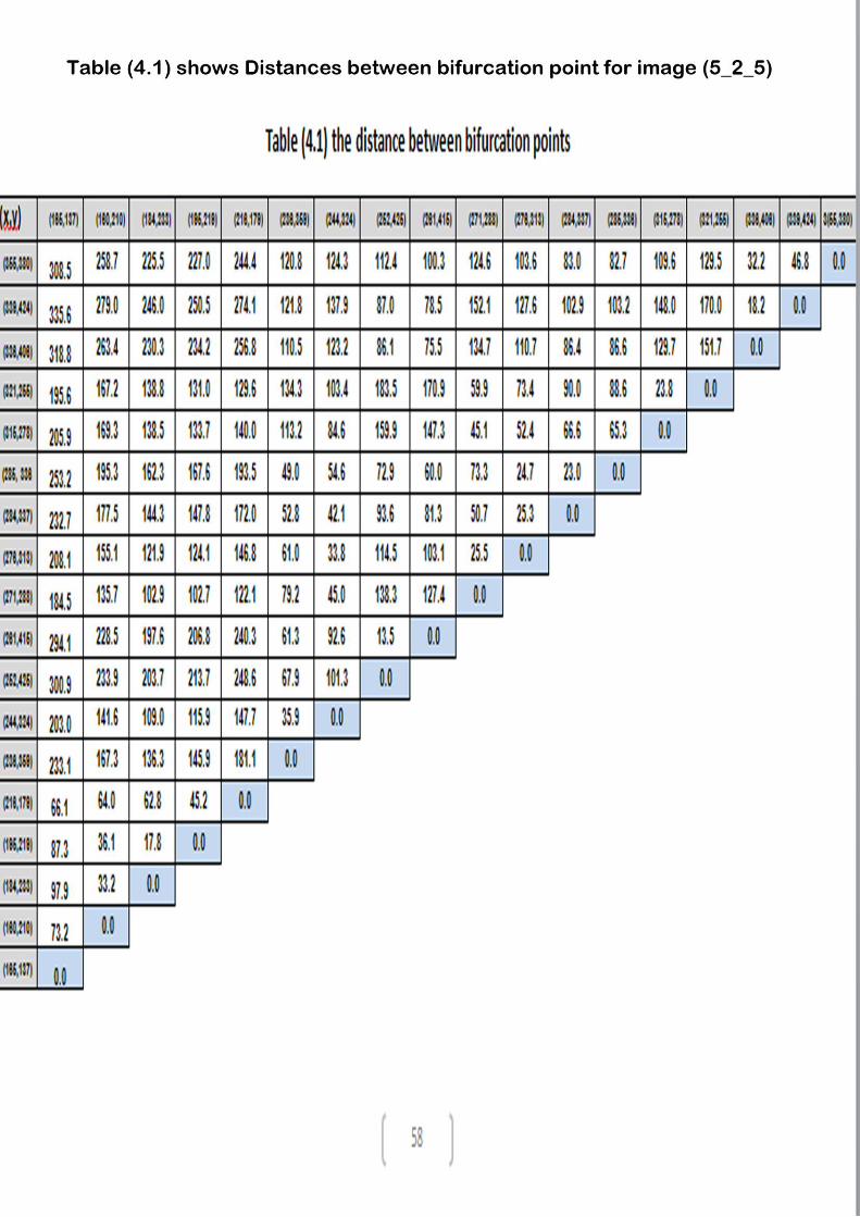
II. Calculate Minimum Distance
In this step, the distances between the detected bifurcation points are calculated,
the Euclidian distance is used between the extracted bifurcation point to the others is
shown in table (4.1).
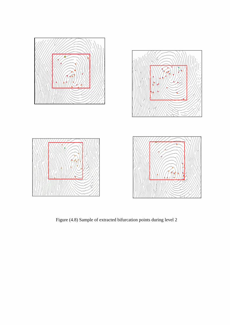
Figure (4.8) Sample of extracted bifurcation points during level 2
4.3.2 Level3 Features Extraction
The PFR technique implemented to perform fingerprint recognition on level3
features is shown in the following processes.
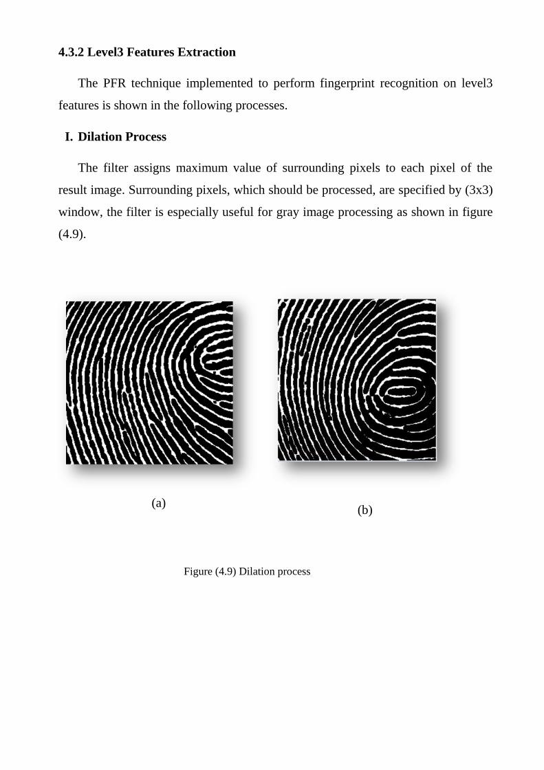
I. Dilation Process
The filter assigns maximum value of surrounding pixels to each pixel of the
result image. Surrounding pixels, which should be processed, are specified by (3x3)
window, the filter is especially useful for gray image processing as shown in figure
(4.9).
(a)
(b)
Figure (4.9) Dilation process
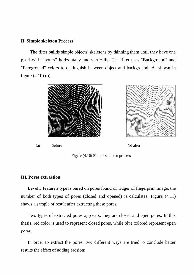
II. Simple skeleton Process
The filter builds simple objects' skeletons by thinning them until they have one
pixel wide "bones" horizontally and vertically. The filter uses "Background" and
"Foreground" colors to distinguish between object and background. As shown in
figure (4.10) (b).
(a) Before (b) after
Figure (4.10) Simple skeleton process
III. Pores extraction
Level 3 feature's type is based on pores found on ridges of fingerprint image, the
number of both types of pores (closed and opened) is calculates. Figure (4.11)
shows a sample of result after extracting these pores.
Two types of extracted pores app ears, they are closed and open pores. In this
thesis, red color is used to represent closed pores, while blue colored represent open
pores.
In order to extract the pores, two different ways are tried to conclude better
results the effect of adding erosion:
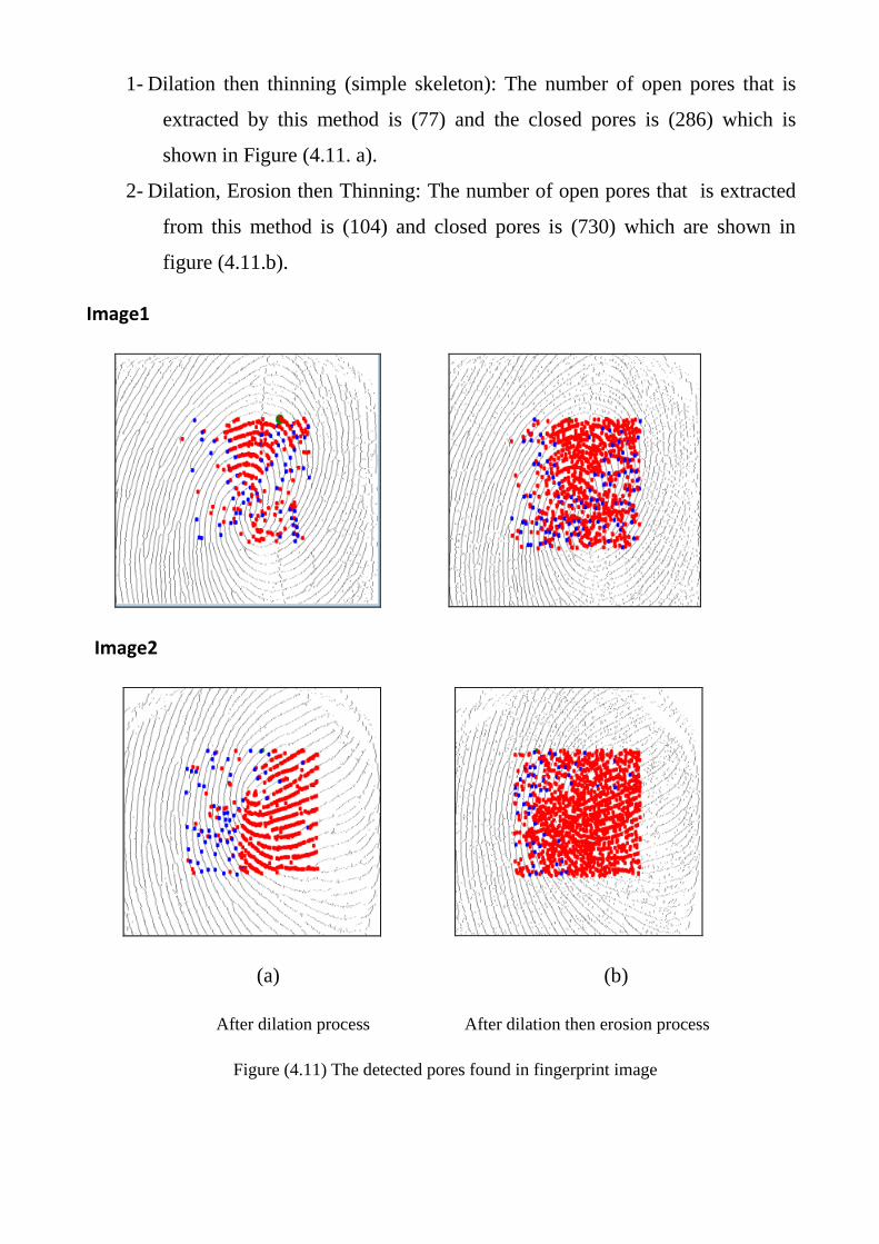
1- Dilation then thinning (simple skeleton): The number of open pores that is
extracted by this method is (77) and the closed pores is (286) which is
shown in Figure (4.11. a).
2- Dilation, Erosion then Thinning: The number of open pores that is extracted
from this method is (104) and closed pores is (730) which are shown in
figure (4.11.b).
Image1
Image2
(a) (b)
After dilation process After dilation then erosion process
Figure (4.11) The detected pores found in fingerprint image
While the result of extracted pores when applying median filter followed by
zhang –Sue algorithm is shown in figure (4.12).
Figure (4.12) pores extraction after applying median filter
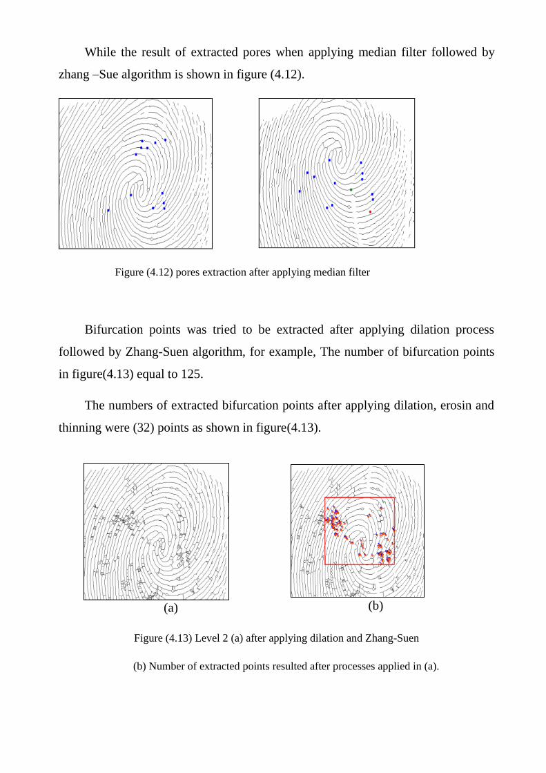
Bifurcation points was tried to be extracted after applying dilation process
followed by Zhang-Suen algorithm, for example, The number of bifurcation points
in figure(4.13) equal to 125.
The numbers of extracted bifurcation points after applying dilation, erosin and
thinning were (32) points as shown in figure(4.13).
(a) (b)
Figure (4.13) Level 2 (a) after applying dilation and Zhang-Suen
(b) Number of extracted points resulted after processes applied in (a).
(a) (b)
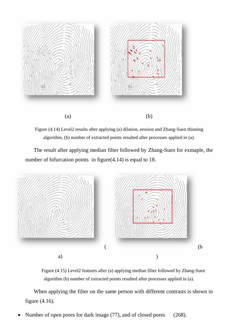
Figure (4.14) Level2 results after applying (a) dilation, erosion and Zhang-Suen thinning
algorithm, (b) number of extracted points resulted after processes applied in (a).
The result after applying median filter followed by Zhang-Suen for exmaple, the
number of bifurcation points in figure(4.14) is equal to 18.
(
a)
(b
)
Figure (4.15) Level2 features after (a) applying median filter followed by Zhang-Suen
algorithm (b) number of extracted points resulted after processes applied in (a).
When applying the filter on the same person with different contrasts is shown in
figure (4.16).
Number of open pores for dark image (77), and of closed pores (268).
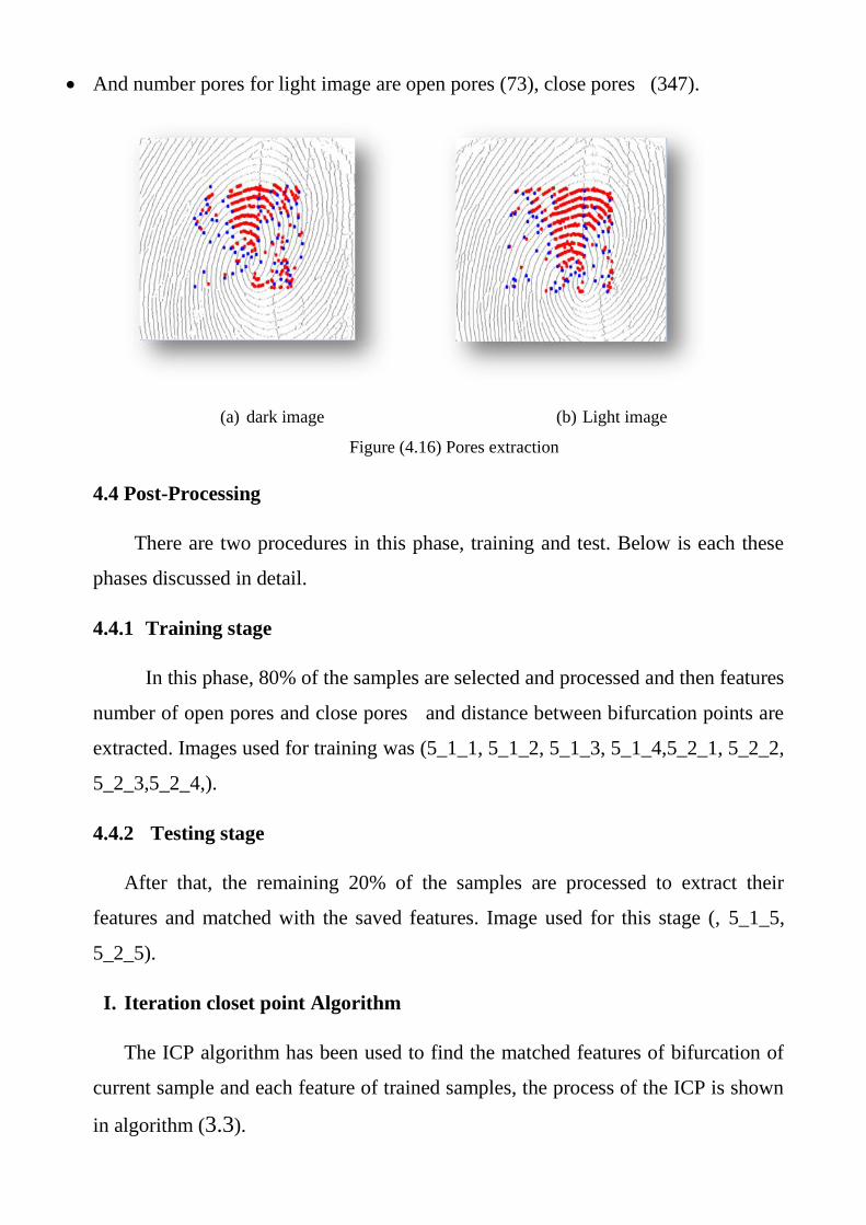
And number pores for light image are open pores (73), close pores (347).
(a) dark image (b) Light image
Figure (4.16) Pores extraction
4.4 Post-Processing
There are two procedures in this phase, training and test. Below is each these
phases discussed in detail.
4.4.1 Training stage
In this phase, 80% of the samples are selected and processed and then features
number of open pores and close pores and distance between bifurcation points are
extracted. Images used for training was (5_1_1, 5_1_2, 5_1_3, 5_1_4,5_2_1, 5_2_2,
5_2_3,5_2_4,).
4.4.2 Testing stage
After that, the remaining 20% of the samples are processed to extract their
features and matched with the saved features. Image used for this stage (, 5_1_5,
5_2_5).
I. Iteration closet point Algorithm
The ICP algorithm has been used to find the matched features of bifurcation of
current sample and each feature of trained samples, the process of the ICP is shown
in algorithm (3.3).
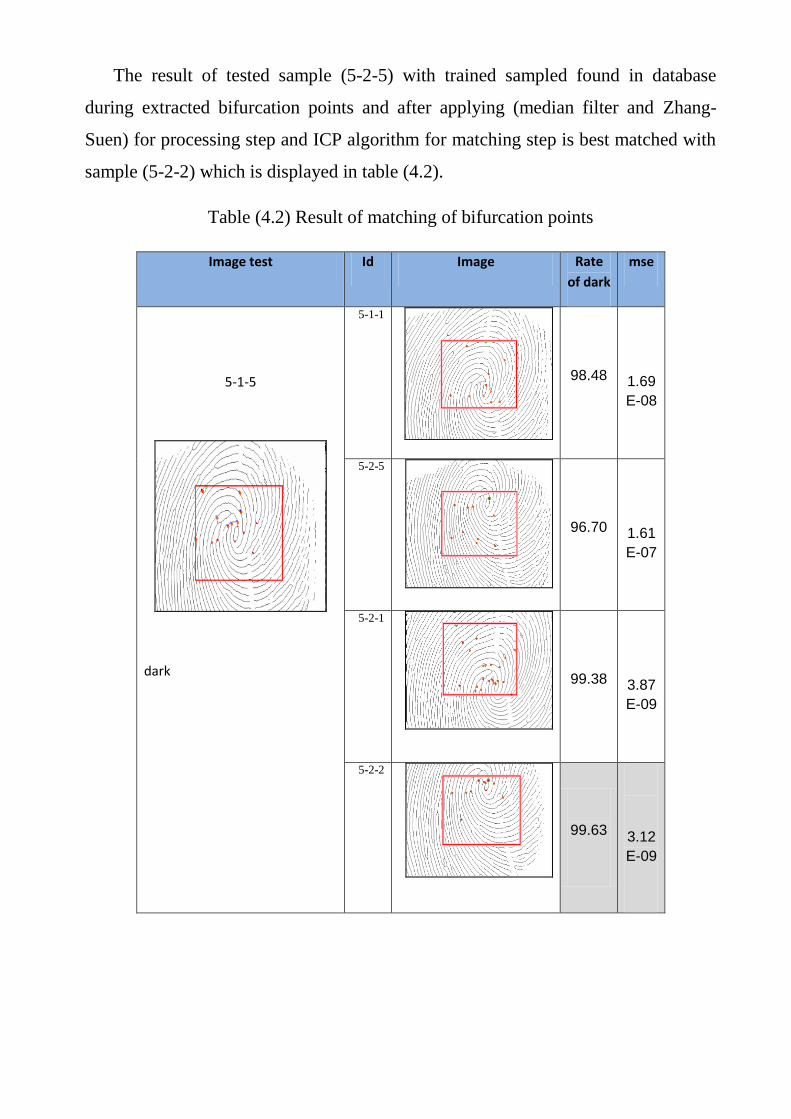
The result of tested sample (5-2-5) with trained sampled found in database
during extracted bifurcation points and after applying (median filter and Zhang-
Suen) for processing step and ICP algorithm for matching step is best matched with
sample (5-2-2) which is displayed in table (4.2).
Table (4.2) Result of matching of bifurcation points
mse Rate
of dark
Image Id Image test
1.69
E-08
98.48
5-1-1
5-1-5
dark
1.61
E-07
96.70
5-2-5
3.87
E-09
99.38
5-2-1
3.12
E-09
99.63
5-2-2
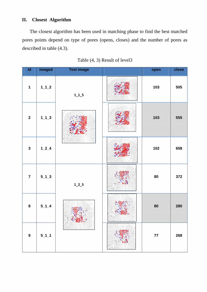
II. Closest Algorithm
The closest algorithm has been used in matching phase to find the best matched
pores points depend on type of pores (opens, closes) and the number of pores as
described in table (4.3).
Table (4, 3) Result of level3
Id imaged Test image open close
1 1_1_2
1_1_5
103 505
2 1_1_3
103 555
3 1_2_4
102 658
7 5_1_3
1_2_5
80 372
8 5_1_4
80 280
9 5_1_1
77 268
Chapter Five
Conclusions and Suggestions
5.1 Conclusions
In the previous chapters, the establishment of recognition and identification
system based on a combination of fingerprint bifurcation and pores extraction was
presented, and the effect of system parameters on its performance have been
illustrated. Several conclusions have been deduced from the obtained test results.
Some of these conclusions are summarized in the following points:
1. The experimental results which use part of an image (160X120) are better
than using an image (320x240) as a whole in time, where the time of
matching for pores (level 3) in case window 320 x 240 are about double the
time required to extract bifurcation points in the whole image. In level 2
matching, the time required for bifurcation point in the whole image is
about 3 times than the time required to extract bifurcation points within a
specific area.
2. The proposed PFR use dilation process to get the stronger pores instead
dilation followed by erosion which gives strong and poor pores.
3. Using median filter in level2 to extract bifurcation points are better than using
dilation in the same level, such that when dilation process is applied in
level2, the number of bifurcation points are 125 and the recognition rate is
(86.7%), While the number of bifurcation points are 18 when using median
filter and the recognition rate is 99.4%.
4. In level 3 using dilation only followed by thinning gives (100 %) recognition
rate for the biometrics ideal test database often the match through closed
and open pores.
5.2 Future Work Suggestions:

This work can be extended in different directions. Below are some suggested
ideas:
1. Using another matching method instead of ICP algorithm such as neural
network algorithm which may increase the discriminating power of the
system.
2. Intelligent techniques may apply during matching phase such as fuzzy logic.
3. An electronic device could plug to monitor system for real-time recognition
or identification.
4. Testing different types of database especially for damaged fingerprint such as
wet fingerprint or engaged.
References
[Abh08] Abhishek Gupta, The Reliability of Fingerprint Pore Area in Personal
Identification, An M.Sc. Thesis, University of Wolverhampton, 2008.
[Abh10] Abhyankar A. and Schuckers S., Towards Integrating Level-3 Features with
Perspiration Pattern for Robust Fingerprint Recognition , IEEE International
Conference on Image Processing, Vol. 3085-3088, Provider: IEEE Publisher:
IEEE , 2010.
[Ack08] Ackerman A., Professor Ostrovsky, Fingerprint Recognition, Journal of
Pharmaceutical and Biomedical Analysis, Vol. 48, pp.554-561, 2008.
[Ari09] Arias-Castro E. and Donoho D.L., Does Median Filtering Truly Preserve
Edges Better Than Linear Filtering, Annals of Statistics, Vol. 37, No. 3, pp.
1172–2009
[Ali14] Ali Ismail Awad and Aboul Ella Hassanien, Impact of Some Biometric
Modalities on Forensic Science, Computational Intelligence in Digital Forensics:
Forensic Investigation and Applications Studies in Computational
Intelligence, Vol. 555, 2014, pp 47-62. 2014
[Bha13] Bhargava N., Bhargava R., Mathuria M. and Dixit P, Fingerprint Minutiae
Matching using Region of Interest, International Journal of Computer Trends
and Technology Vol. 4, pp:515-518, 2013.
[Che07] Chen Y. and Jain A. K., Dots and Incipient: Extended Features for
Partial Fingerprint Matching, Biomet b rics Symposium Pages:1-
6 Provider: IEEE Publisher: IEEE 2007.
[Cha12] Chandra Prakash Singh, Anurag jain ,Ashish Khare 3Susheel Jain,
Fingerprint Recognition Using level3 Feature Extraction Method and
Matching Using SIFT Algorithm, IRACST - International Journal of Computer Science
and Information Technology & Security (IJCSITS), ISSN: 2249-9555 Vol. 2, No.5, October 2012.
[Dav13] Davit K., A Modified Fingerprint Image Thinning Algorithm, American
Journal of Software Engineering and Applications; Vol. 2, No. 1, 2013.
[Div14] Divyaloshini V. and Mrs. Saraswathi M., Performance Evaluation of
Image Fusion Techniques And Its Implementation In Biometric
Recognition, International Journal of technology enhancements and emerging
engineering research, Vol 2 Issue 3, march 2014.
[Gre84] Nehemiah Grew, "The description and use of the pores in the skin of the
hands and feet ",by the Learned and Ingenious Nehemiah Grew, M. D.
Fellow of the College of Physicians and of the Royal Society , vol. 14, pp.
566-567 (1684).
[Iwa12] Iwasokun G. B., AkinyokunOluwole C., Olabode Olatubosun, Fingerprint
Image Enhancement: Segmentation to Thinning, International Journal of
Advanced Computer Sciences and Applications Vol. 3 , Issue 1 , 2012.
[Jai06] Jain, A. , Yi Chen ,Demirkus, M. , Pores and Ridges: Fingerprint
Matching Using Level 3 Features, IEEE, 18th International Conference on
Pattern Recognition (ICPR'06) Vol:4 Pages: 477-480 ,2006.
[Jai07] Jain, A. K., Chen, Y. and Demirkus, M., Pores and Ridges: High
Resolution Fingerprint Matching Using Level 3 Features, IEEE
Transactions on Pattern Analysis and Machine Intelligence Vol. 29 , Issue: 1,
2007 .
[Jai08] Jain, A.K. , Jianjiang Feng , Nagar, A. , and Nandakumar, K., On Matching
Latent Fingerprint, Computer Society Conference on Computer Vision and
Pattern Recognition Workshops , Pages: 1-8 ,2008.
[Jea05] Tsai-Yang Jea, Venu Govindaraju, A Minutia-based Partial Fingerprint
Recognition System, Pattern Recognition Society, Published by Elsevier Ltd,
Vol. 38, No. 10, 2005.
[Joh05] John Clifford Gower, Euclidean Distance Matrix, Dattorro. co&edg
version , All rights reserved.citation: Dattorro, Convex Optimization &
Euclidean Distance Geometry,M Publishing USA, 2005.
[Kal11] Kalyani M. and Samay I. B., Fingerprint Recognition Using Global and
Local, International Journal on Computer Science and Engineering, Vol.
3 Issue: 1, 2011.
[Krz04] Krzysztof, K. M., Morier, P. and Drygajlo, A. , Study of the
Distinctiveness of Level 2 and Level 3 Features in Fragmentary Fingerprint
Comparison, Lecture Notes in Computer Science Vol. 3087, 2004.
[Kur94] Kurt E. Kuhn, The fingerprint Science and Ridgeology, Identification
Supervisor, Beverly Hills Police Department, 1994.
[Kum10] Kumar R. L., Sai K.S., Fingerprint Minutia Match Using Bifurcation
Technique, International Journal of Computer Science , Vol 2, issue 4, 2010.
[Lan01] Langis C., Greenspan M. ,Godin G.,TheParallel Iterative Closest Point
Algorithm, Journal: 3-D Digital Imaging and Modeling,. Proceedings. Third
International Conference on ISBN, pages: 195-202 Provider: IEEE Publisher:
IEEE Comput,2001.
[Lee01] Lee H. C. and Gaensslen R. E. ,Advances in Fingerprint Technology,
Second Edition , eBook 2001 .
[Mel13] Mela Gh. Abdul-haleem A., A Spatial Invariant Model for Local Attributes
of Fingerprint Ridges, An M. Sc., thesis Submitted to the College of Science,
Baghdad University, 2013.
[New06] Newmann, C., Champod, C., Puch-Solis, R., Egli, N., Anthonioz, A.,
Meuwly, D. and Griffiths A.B., 2006., Computation of Likelihood Ratios in
Fingerprint Identification for Configurations of Three minutiae, Journal of
Forensic Science, Vol. 51, No. 6, pp. 1255-1266, 2006.
[Ned] Nedia Fadhil Muhsain, Fingerprint Recognition using Prepared Codebook
and Back-propagation , Al-Mansour Journal/ Issue (15) 2011.
[Ots79] Otsu N.,A Threshold Selection Method from Gray-Level Histograms, IEEE
Transactions on Systems ,Man, and Cybernetics, vol. 9, no. 1,1979.
[pac12] Pachiyappan, Arulmozhivarman , Das Undurti N. , Murthy Tatavarti
VSP , Tatavarti Rao , Automatic Diagnosis of Diabetic Retinopathy Using
Fundus Image, ournal: Lipids in Health and Disease, Vol: 11 , 1 Pages: 73-73
Publisher: BioMed Central ,2012.
[Par98] Park, Sang Ho and, Morphological Approach for Image Segmentation,
Journal of pattern recognition, Vol. 31, No. 5, pp 1063-1068, 1998.
[Pat13] Patel H., Mr. Vishal Sh., Fingerprint Recognition by Minutiae Matching
Method for Evaluating Accuracy, International Journal of Engineering Trends
and Technology ,Vol. 4 issue 5, 2013.

[Pra01] Prabhakar S, Fingerprint Classification and Matching Using a Filter Bank,
Ph. D. Submitted to Michigan State University, Computer Science & Engineering
department, 2001.
[Pro04] ProZone, Transactions on Circuits and Systems for Video Technology, Special
Issue on Image- and Video-Based Biometrics, Vol. 14, No. 1, January 2004.
[Qij01] Qijun Z., Lei Z., David Z. and Nan L., Adaptive Fingerprint Pore Modeling
and Extraction, Pattern Recognition Vol. 43 Issue: 8, Pp: 2833-2844, 2010.
[Rav06] Ravi D. Keesing , An Introduction to Biometrics, Journal of Documents &
Identity, issue 17, 2006.
[Rol11] Roli B., Priti S., and Punam B., Minutiae Extraction from Fingerprint
Images – Review, International Journal of Computer Science , Vol. 8, No 3. ,
2011.
[Shi10] Shih F.Y., Image Processing and Pattern Recognition: Fundamentals and
Techniques, Wiley-IEEE check Press, Page(s): 1 - 16, 2010.
[Sin09] Singh R., Shah U., Gupta V., Fingerprint Recognition, Project Report
Computer Vision and Image Processing; Indian Institute of Technology, 2009.
[Sra12] Sravya. V, Radha K. M., RavindraBabuKallam, Srujana B, A Survey on
Fingerprint Biometric System, Aizza College of Engineering & Technology,
Mancherial India, Vol. 2, Issue 4, 2012.
[Szy01] Szymon Rusinkiewicz & Marc L., Efficient Variants of the ICP Algorithm,
Stanford University, book,2001.
[Tha10] Thai Le H., Tam Ha N. Fingerprint Recognition using Standardized
Fingerprint Model, International Journal of Computer Science, Vol. 7 Issue 3,
2010.
[Uma05] Uma D. Nadimpalli, Image Processing Techniques to Identify Predatory
Birds, B.E. Visakhapatn Andhra University theiss 2005.
[wab13] Wable S. , Laulkar Ch., Role of Assembling Invariant Moments and SVM
in Fingerprint Recognition, International Journal of Computer Science and
Network, Vol. 2, Issue 3, 2013.
[You11] Young Ho P., Dat N. Tien , Hyeon Ch. Lee and Kang R. Park , A
Multimodal Biometric Recognition of Touched Fingerprint and Finger-Vein,
International Conference on Multimedia and Signal Processing Vol. 1 , 2011.
[Zha09] Zhao Q., Lei Zh., David Zh., and Nan L., Direct Pore Matching for
Fingerprint Recognition, Biometrics Research Centre, Department of
Computing, The Hong Kong Polytechnic University, Kowloon, Hong Kong,
LNCS 5558, pp. 597–606, © Springer-Verlag Berlin Heidelberg 2009.
[Zha10] Zhao Q., David Zh., Lei Zh., Nan Luo, Adaptive fingerprint pore modeling
and extraction, Pattern Recognition Biometrics Research Centre, Department of
Computing, The Hong Kong Polytechnic University, Hung Hom, Kowloon, Hong
Kong vol. 43(8), pp. 2833-2844, 2010.
Related Documents