Minerals 2020, 10, x; doi: FOR PEER REVIEW www.mdpi.com/journal/minerals Conference Proceedings Paper Fine, Coarse and Fine-Coarse Particle Flotation in Mineral Processing With A Particular Focus On The Technological Assessments Ahmad Hassanzadeh 1, *, Mehdi Safari 2 and Duong Huu Hoang 3 1 Independent Scholar, Am Apostelhof 7A, 50226 Frechen, North Rhine-Westphalia, Germany; [email protected] 2 Centre for Minerals Research, Department of Chemical Engineering, University of Cape Town, Private Bag Rondebosch, Cape Town 7700, South Africa; [email protected] 3 Maelgwyn Mineral Services Ltd, Ty Maelgwyn, 1A Gower Road, Cathays, Cardiff, CF24 4PA, United Kingdom; [email protected] * Correspondence: [email protected]; Tel.: +4917620666711 (A.H.) Received: date; Accepted: date; Published: date Abstract: After more than a century applying flotation to the mining industry, two completely different strategies have been introduced for processing purposes. One is the classical approach viz. grinding the ores to certain extend and floating them via conventional mechanical and recently pneumatic cells e.g. Jameson and Imhoflot TM cells. This strategy continuous because mines face up to declining cut-off grades, complex and poly-mineralized ores, and they require to achieve an acceptable degree of mineral liberation. The other school of mind deals with the coarse particle processes mainly owing to the low energy needs, that includes flash, fluidized bed and HydroFloat TM cells. The third and newest system proposes processing both fine and coarse sizes by flotation machines like oscillating grid flotation (OGC) and Reflux flotation cells. The present paper endeavours to critically evaluate these concepts from several points of view including existing technological elaborations, water and energy usages, kinetics and circuit design. Brief introduction of advanced technologies, along with their applications, were presented. It was revealed that the incorporation of coarse grinding apparatuses, mineralogical techniques together with the technologically applicable classification systems and adapted simulator tools are urgent needs for coarse flotation as the future requirements for mining industries. However, fine particle flotation may remain as the main focus of re-processing tailings dams. Keywords: Flotation cells; fine and coarse particles; technological development; flotation kinetics; HydroFloat TM cells 1. Introduction Froth flotation was undoubtedly the most innovative and mining saver in ore dressing in the 19th century [1]. Nevertheless, it did not last long that scientists recognized its limitations for extremely fine (<20 μm) and coarse particles (>150 μm) which have been remained as a long-standing unsolved issue in the mineral processing field [2]. From the early 20th century, many active industries applied the simplest solution to tackle this issue by increasing flotation cell size [3] with paying less attention to designing an efficient cell. This strategy has been a matter of argument over many years, which the present paper points this out by categorizing it into mainly two subdivision groups.

Welcome message from author
This document is posted to help you gain knowledge. Please leave a comment to let me know what you think about it! Share it to your friends and learn new things together.
Transcript
Minerals 2020, 10, x; doi: FOR PEER REVIEW www.mdpi.com/journal/minerals
Conference Proceedings Paper
Fine, Coarse and Fine-Coarse Particle Flotation in
Mineral Processing With A Particular Focus On The
Technological Assessments Ahmad Hassanzadeh 1,*, Mehdi Safari 2 and Duong Huu Hoang 3
1 Independent Scholar, Am Apostelhof 7A, 50226 Frechen, North Rhine-Westphalia, Germany;
[email protected] 2 Centre for Minerals Research, Department of Chemical Engineering, University of Cape Town, Private Bag
Rondebosch, Cape Town 7700, South Africa; [email protected] 3 Maelgwyn Mineral Services Ltd, Ty Maelgwyn, 1A Gower Road, Cathays, Cardiff, CF24 4PA, United
Kingdom; [email protected]
* Correspondence: [email protected]; Tel.: +4917620666711 (A.H.)
Received: date; Accepted: date; Published: date
Abstract: After more than a century applying flotation to the mining industry, two completely
different strategies have been introduced for processing purposes. One is the classical approach
viz. grinding the ores to certain extend and floating them via conventional mechanical and recently
pneumatic cells e.g. Jameson and ImhoflotTM cells. This strategy continuous because mines face up
to declining cut-off grades, complex and poly-mineralized ores, and they require to achieve an
acceptable degree of mineral liberation. The other school of mind deals with the coarse particle
processes mainly owing to the low energy needs, that includes flash, fluidized bed and
HydroFloatTM cells. The third and newest system proposes processing both fine and coarse sizes by
flotation machines like oscillating grid flotation (OGC) and Reflux flotation cells. The present paper
endeavours to critically evaluate these concepts from several points of view including existing
technological elaborations, water and energy usages, kinetics and circuit design. Brief introduction
of advanced technologies, along with their applications, were presented. It was revealed that the
incorporation of coarse grinding apparatuses, mineralogical techniques together with the
technologically applicable classification systems and adapted simulator tools are urgent needs for
coarse flotation as the future requirements for mining industries. However, fine particle flotation
may remain as the main focus of re-processing tailings dams.
Keywords: Flotation cells; fine and coarse particles; technological development; flotation kinetics;
HydroFloatTM cells
1. Introduction
Froth flotation was undoubtedly the most innovative and mining saver in ore dressing in the 19th
century [1]. Nevertheless, it did not last long that scientists recognized its limitations for extremely
fine (<20 μm) and coarse particles (>150 μm) which have been remained as a long-standing unsolved
issue in the mineral processing field [2]. From the early 20th century, many active industries applied
the simplest solution to tackle this issue by increasing flotation cell size [3] with paying less attention
to designing an efficient cell. This strategy has been a matter of argument over many years, which
the present paper points this out by categorizing it into mainly two subdivision groups.
Minerals 2020, 10, x FOR PEER REVIEW 2 of 13
Generally speaking, three key points force the mining industries to coarse particle treatment
containing I) drastic environmental consequences of wet tailings dams and acid mining drainage
(AMD), II) losing precious materials in the coarse fraction sizes and III) enormous energy
consumption (i.e., 2-4% global electricity usage) in comminution stages with less than 2% efficiency
[4]. Although these concepts are well established, only a few technological developments have been
appeared in mineral processing industries over the last decades. Microwave technology [5-6], high
pressure grinding rolls (HPGR), and pneumatic type flotation cells are the major illustrations in this
regard. The most recent industrial examples might be the commercialized rapid microwave and
Nova CellTM. The former is the microwave (MW)-assisted grinding [7] which leads to a remarkable
increase in material’s grindability, improvement of mineral liberation degree and reduction of the
comminution energy over 30%. The latter is a developed flotation machine (Nova CellTM) shows
saving in operating costs of grinding energy and media by 40% and 12% decrease in overall site
operating cost [8].
In an industrial scale, up- and down-stream operating units (e.g. de-watering, grinding and
classification) inevitably affect metallurgical responses of a flotation process. Thus, the efficiency of
either coarse or fine particle treatment systems is inherently coupled with the performance of these
units. For example, processing of rare earth elements (REEs) embedded in carbonate,
fluorocarbonate, phosphate and fluorite deposits faces with massive challenges concerning their
extremely low grades which leads to being ground finely for achieving a desirable liberation degree
[9]. Poor recovery of fine particles is mainly related to the low frequency of collision between
particles and bubbles (Zpb) [10-14], high specific surface area, high surface energy and most
importantly low particle inertial force [15]. Technically speaking, to improve fine particles recovery
in flotation, one must whether increase the particle size or decrease the bubble diameter. In this
regard, the particle sizes can be enlarged by flocculants, while the small bubbles can be generated via
dissolved-air flotation, induced-air flotation, hydrodynamic cavitation, electro-flotation and
microbubble generators. The most common belief is creating an intense turbulent environment to
increase particle-bubble collision efficiency (Ec), which is an extremely energy-consuming process
[16-18]. Other than those, it was indicated at the OK Tedi plant that sulphidization by NaHS could
improve copper recovery of fine particles (<20 μm) up to 3.4% [19]. Shear flocculation or
high-intensity conditioning (HIC) is another technique used to upgrade the recovery of fines [20].
Mechanical vibration and the acoustic wave pre-treatments is also reported as a promising approach
to enhance the recovery of fine fraction sizes up to ca. 3.5% by a cleaning effect on the surface of the
minerals and generation of heterogeneous nucleation of microbubbles on the particle surfaces
[21-22].
Some researchers worked on overcoming the challenges of fine and coarse particle flotation systems.
Jameson [23] presented theoretical backgrounds regarding the main difficulties in recovering
ultra-fine and coarse particles. He developed Concorde™ flotation cell and applied fluidization
principles to upgrade recovery of ultra-fine (nickel sulphide and platinum ores) and coarse particles
(galena) by a factor of ten. Recent advances in FLSmidth Inc. as a pioneer company in flotation
processes can be classified into three groups as I) forced-air flotation machines (Dorr-Oliver)
designed for recovering fine particles in terms of imposing high energy to these particles concerning
their low inertia in tiring down the water film. II) induced-air flotation cells (Wemco) favourable for
recovering coarse particles since these particles can be collected next to the surface and the travel
distance to froth from the discharge lip is reasonably short. III) forced-air and induced-air cells
(Dorr-Oliver and Wemco) in a circuit with the idea of recovering both fine and coarse sizes using a
combination of the two technologies in the same row/bank or different flotation stages [24].
The present paper aims at introducing technological barriers that the froth flotation currently faces
up with a particular focus on the identification of challenges and opportunities for treating coarse
and fine particles.
Minerals 2020, 10, x FOR PEER REVIEW 3 of 13
2. 2. Limitation of mineralogical approaches
Selection of fine or coarse particulate systems strongly requires a precise and appropriate
mineralogy characterization approach. Recent developments indicated that X-ray computed
micro-tomography (μCT) and mineral liberation analyzer (MLA) have been extensively utilized to
characterize a variety of particle properties in the scope of process mineralogy for coarse and fine
particle sizes, respectively [25]. The μCT is a non-invasive 3D technique that allows to image the
distribution of minerals inside a sample while scanning electron microscopy-based methods like
MLA and QEMSCAN (quantitative evaluation of materials by scanning electron microscopy (SEM)).
It allows for a 2D quantitative analysis of mineral essays by combining backscattering electron (BSE)
images with energy-dispersive X-ray spectroscopy (EDS) [26]. The low resolution (tens of microns)
and the lack of chemical information have typically limited the application of μCT to identify and
analyze fine particles. Nevertheless, it remains unclear how coarse a particle must be to be accurately
measured by μCT [27].
From industrial perspectives, it is now possible to on-site measure particle characteristics in the
range of 1-150 mm with a voxel resolution of approximately 100 μm at the sampling rate of 1 kg/min
using high-speed X-ray computed tomography (HSXCT). Detailed information concerning the
on-site measurements for coal washability, crusher plant products and pebble phosphates case
studies can be found elsewhere [28-29]. Also, recent studies have manifested that the MLA and
QEMSCAN cannot be applied in-situ and for coarse particle sizes [30]. For fine particles, it
unavoidably suffers from a stereological bias along with a statistical dispersion in the light of the
number of analyzed particles [31] which results in an overestimation of mineral liberation degrees.
Moreover, there are natural uncertainties inherently linked to representativity and sample
preparation shortcomings [32]. According to the raised assertions, there is an urgent need to tackle
these issues related to either coarse or fine process mineralogies.
3. Fine or coarse particulate systems
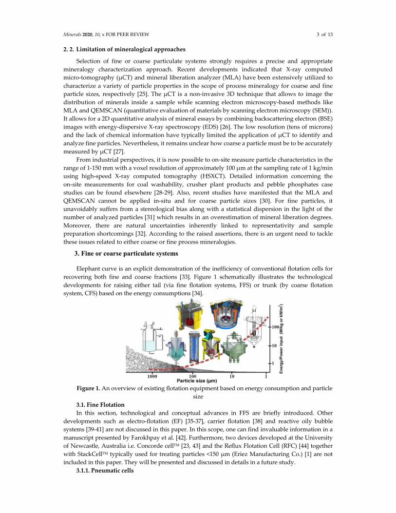
Elephant curve is an explicit demonstration of the inefficiency of conventional flotation cells for
recovering both fine and coarse fractions [33]. Figure 1 schematically illustrates the technological
developments for raising either tail (via fine flotation systems, FFS) or trunk (by coarse flotation
system, CFS) based on the energy consumptions [34].
Figure 1. An overview of existing flotation equipment based on energy consumption and particle
size
3.1. Fine Flotation
In this section, technological and conceptual advances in FFS are briefly introduced. Other
developments such as electro-flotation (EF) [35-37], carrier flotation [38] and reactive oily bubble
systems [39-41] are not discussed in this paper. In this scope, one can find invaluable information in a
manuscript presented by Farokhpay et al. [42]. Furthermore, two devices developed at the University
of Newcastle, Australia i.e. Concorde cellTM [23, 43] and the Reflux Flotation Cell (RFC) [44] together
with StackCellTM typically used for treating particles <150 μm (Eriez Manufacturing Co.) [1] are not
included in this paper. They will be presented and discussed in details in a future study.
3.1.1. Pneumatic cells
Minerals 2020, 10, x FOR PEER REVIEW 4 of 13
Pneumatic flotation technology was originally developed in the 1970s by Bahr et al. [45] at the
Technical University of Clausthal (Germany) and Simonis et al. [46] at the Technical University of
Berlin (Germany) which the cell was so-called Bahr cell. The first research work was initiated in 1973
while the prototyped model was built up in 1978. It is well documented that the pneumatic flotation is
more effective than the conventional cells in terms of recovering fine particles [47]. The pneumatic and
traditional flotation cells differ concerning a requirement for compressed air and agitation, which
consequences substantial energy saving in pneumatic ones [48]. Most recently, Safari et al. [49] pointed
out this by reverse flotation of iron ore utilizing mechanical, oscillating grid and pneumatic cells. They
manifested that the pneumatic flotation cell shows the best flotation performance for most operating
conditions. Lima et al. [50] addressed the same concept by comparatively analyzing mechanical and
pneumatic cells for quartz flotation. Two commonly used pneumatic flotation machines are JamesonTM
and ImhoflotTM cells discussed as follows.
3.1.2. Jameson Cell
There have been about 350 Jameson Cells installed in a variety of coal (especially in Australian
coal industry), metalliferous and industrial mineral application worldwide [51-52]. This type of
flotation cell was used for upgrading final grade and increasing capacity issues of conventionally
operated flotation cleaner circuits [53]. It was initially developed as a low-cost alternative to traditional
column flotation cells for recovering fine particles. It was firstly installed at Mount Isa lead-zinc
concentrator in 1988 and successfully recovered fine particles (<12 μm). Higher lead grade in
concentrate (60%) was reported compared to the conventional cleaning circuit (51%). The Jameson Cell
was successfully operated in the cleaning stage to treat the porphyry gold-copper ore in Minera
Alumbrera Ltd in Argentina resulting in respectively gold and copper recoveries of about 80% and
90% for particles finer than 10 μm [54].
Technically, the cell works by closing the air inlet at the top of the downcomer while feeding the
flotation pulp through the nozzle leads to the high-intensity particle-bubble contacting [55]. The feed is
pumped into the downcomer through an orifice plate, and create a high-pressure jet where the
plunging jet of liquid shears and entrains air [56]. It results in a rapid contact and collection of particles
and bubbles in high mixing velocity and a large interfacial area, which ultimately consequences
extremely short residence time. A vital privilege of this type of cell to the traditional mechanical cells is
its faster kinetics rate. This relates to the gas holdup in a confined downcomer which is typically far
higher than that of a conventional flotation vessel, reaching in some cases up to 60% [57]. However, the
typical mean residence time (MRT) of a mechanical cell circuit is about 4-20 min for a rougher stage,
depending on the mineral type and the number of cells in a bank, and up to 30 min for scavengers,
while for a flotation column is in the range of 18 to 23 min, depending on the column design [58]. In
this scope, Harbort et al. [59] reported a reduction in MRT of a mechanical rougher-scavenger circuit
(17.9 min) and cleaner-scavenger circuit (30 min) down to 7.5 min and 2.5 min using Jameson cells with
identical flotation performances.
3.1.3. ImhoflotTM cell
The history and development of ImhoflotTM pneumatic flotation cells are well documented in
several technical reports [60-62]. The commercialization began in the early 1980s. From designing
perspective, it differs from the conventional cells in that the particle-bubble collision takes place
outside of the cell, within the aerator (called as a pipe flotation) [47]. Similar to HydroFloatTM and
column flotation cells, it does not require compressed air and agitation, which provides the
opportunity of saving a tremendous amount of energy compared to the traditional mechanical cells.
The energy input goes more directly into the particle-bubble collision, rather than energy being used to
maintain the pulp in suspension as in mechanical cells. The slurry is pumped with enough fluid
energy to produce intensive aspiration of air and rapid dispersion for efficient particle-bubble collision
[63]. The method of self-aspiration of ImhoflotTM flotation is based on the well-known venturi
principal. However, the patented design has a complex system of nozzles, impingement plates and gas
hold up mechanisms that generates a spectrum of fine bubble size. Maeqwyn ImhoflotTM flotation cell
has three different types, i.e., vertically fed (V-cell), tangentially fed (G-cell) and another type called
H-cell, which is similar to the G-cell. This type enables to introduce feed vertically via a separate
Minerals 2020, 10, x FOR PEER REVIEW 5 of 13
distributor box located at the base of the tank. The design of the ImhoflotTM cell type depends on the
particle size. The V-cell is generally used for the intermediate and coarse particle (i.e. 50-300 μm)
flotation while the residence time is approximately 3 min. ImhoflotTM G-cell is favoured for very fine to
intermediate-sized particles (i.e. <50 μm) with a very short residence time of approximately 1 min
depending on the particle size, mineral characteristics i.e., mineral hydrophobicity, association, and
liberation. The ImhoflotTM flotation cell including G-cell has been successfully applied to the mineral
processing and recycling industries in the last two decades and practically demonstrated its capability
in recovering ultra-fines. The application of a three stages Imhoflot G-Cell at a nickel operation plant in
Europe showed its ability to recover approximately 30% Ni from the final tailings, predominantly in
the <11 μm size fraction. Further, a two-stage Imhoflot G-Cell plant was established at a zinc operation
to avoid losing fine intergrowth 7 μm particles. It recovered ca. 20% of the zinc from the final cleaner
tailings [47].
3.1.4. Floc-flotation
As noted earlier, the principle issue related to poor floatability of fine and ultrafine particles is
generally attributed to their low momentum and inertial force under conventional hydrodynamic and
thermodynamic properties of flotation cells [64-65]. This leads to a low probability of Ec and
consequently, poor flotation kinetics rate constant [66-67]. Floc-flotation is a technique to aggregate the
fine particles using a polymer flocculant, hydrophobic interactions and micro-organisms to obtain
coarse-sized particles a.k.a. flocs to tackle those issues. There are many successfully reported
achievements in a laboratory scale for coal [68], malachite [69], hematite [70], quartz and galena [71],
calcite and talc [72]. However, yet only one unique industrial illustration operating since 1974 is Tilden
nonmagnetic taconite concentrator located in the U.S.A. [73]. The main crucial aspect of this process is
related to the type of polymer and low selectivity separation due to heterocoagulation and entrapment
phenomena. More detailed information can be found elsewhere [74].
3.2. Coarse flotation
Few research studies showed approximately 2% improvement in the recoverability of coarse
particles by distributing chemical reagents throughout the flotation circuit [75-77]. Nevertheless,
coarse particle treatment by the conventional flotation machines is nearly impossible due to essential
needs for a massive amount of energy for material suspension, high particle-bubble detachment
probabilities, low retention time and limitations regarding the buoyancy force of the bubbles. The
following section highlights two examples in terms of treating coarse fraction sizes, focusing on Flash
flotation and HydroFloatTM technology.
3.2.1. Flash flotation
The flash flotation cell (SkimAir® Courtesy Outotec (formerly Outokumpu)) proposed in the
early 1980s to flash off fast-floating liberated minerals of high value. It has been broadly used but not
well understood for processing complex ores containing coarse (-212+38 μm) or free gold [78]. It was
designed to avoid over-grinding of the valuable dense sulfide minerals in circulating load of primary
milling circuits that allows floating coarse particles with high-grades in early flotation stages [79].
Technically, flash flotation enables a concentration plant to minimize over-grinding, enhance overall
recovery, increase mill throughput and improve dewatering through shrinkages filter costs and
diminishes final concentrate moisture. Its feed (up to 1800 tph) is normally the hydrocyclone
underflow with high slurry % solids (up to 70%), which the flash flotation tailings recirculate into the
grinding unit. One important privilege, which is often overlooked, is that the SkimAir® provides a
buffer for the conventional flotation circuit to produce a more stable feed when the feed grade is highly
variable. Another advantage of the flash flotation is the minimal contact time of particles with reagents
and almost no conditioning stage prior to the flotation. Detailed description of the process of flash
flotation was presented by Newcombe et al. [80].
3.2.2. Erize HydroFloatTM technology
HydroFloatTM is an aerated conical-shaped fluidized-bed (teeter-bed) separator which
synergistically combines flotation with gravity/elutriation techniques enhancing the recoverability of
middling (>150 μm), coarse (<2000 μm) and poorly liberated particles. In early 2000s, several
proof-of-concept trials were carried out at laboratory and pilot scales (phosphate [81]) concerning its
Minerals 2020, 10, x FOR PEER REVIEW 6 of 13
application for mostly sulfide type ores as well as potash (Canada), coal, vermiculite (U.S.A.),
spodumene (Australia) and diamonds (Canada) [82]. The first full-scale industrial unit (3 m diameter)
was commissioned at PotashCorp’s Rocanville potash mill to treat approximately 125 t/h of coarse
tailings. It upgraded the potash recovery from approximately 50% to over 90% [83]. Mosaic’s South
Fort Meade Mine [84] and PotashCorp’s Aurora beneficiation plant [85] were other successful
examples. The initial sulfide mineral full-scale (3.4 m diameter) installation and operation was
performed on rougher flotation tailings (-300+150 μm) of a copper ore at Newcrest’s Cadia Valley,
New South Wales, Australia in 2018.
Practically, three zones within the vessel in a top-down design are as i) free settling phase with
low solids concentration, ii) fluidized bed with nearly plug-flow mixing regime, and iii) dewatering
zone with higher % solids (ca. 60%). This design induces floatability improvements by maximizing
Zpb and particle residence time together with a minimization of axial mixing, particle-bubble
detachment rate, turbulence and froth buoyancy restrictions [86]. One crucial advantage of the Erize
HydroFloatTM to the conventional cells is extremely low (1%) necessity of mineral surface
hydrophobization (>800 μm) and no agitation mechanism [87]. It also leads to not only reduction of
capital and operating costs but also improves sustainability, tailings management and environmental
aspects [88]. Most importantly, it shows an enormous drop-off of grinding energy consumption and
20-25% increase in mill throughput depending on the application.
3.3. Fine and coarse flotation
Typical overall flotation recoveries in many of mineral industries are between 80-90%, and as
shown in previous reports [89, 90] virtually in all operating concentration plants, most of the losses are
in particle sizes below 20 μm (50%) and above 150 μm (30–40%) fractions. The third ideology is to
apply advance technologies allowed to float both these extreme sizes. As an example, considering
copper alone, assuming an average loss of ~10%, the flotation loss described could amount to at least
1.5 million tonnes per year, with a cash value of $10 Billion. The real problem is that over 99% of what
is mined in the precious metal industry is considered waste. Therefore, coarse particle flotation could
allow mines to reject some waste earlier in the process before the fine flotation circuit, which might
help to reduce capital and operating costs.
Each flotation cell is designed for targeting specific particle size range based on its hydrodynamic
properties. It is a problem with both fine and coarse particle recovery that have been the focus of many
subsequent novel cell developments. Most of these systems attempt to improve the fine or coarse
particle recoveries. Therefore, it is good to have a flotation cell that floats both fine and coarse particles.
The idea is that it would be part of a split circuit, presorted into coarse and fine, with technologies
tailored to each. To float both size ranges, the following sections exemplify two vessels developed in
bench-scale including oscillating grid cell (OGC) and reflux flotation cell (RFC).
3.3.1. Oscillating grid flotation cell
In the past two decades, a considerable amount of research has been undertaken in flotation,
especially in the flotation cells. Research into flotation cells has focused on the development of new
flotation cell technologies from a better understanding of the impact of cell hydrodynamics on the
sub-processes of flotation. Several excellent studies into the effect of energy on flotation kinetics have
been carried out in impeller stirred cells [91-95]. Investigations using this type of cell have a number of
limitations such as the impeller influences particle suspension, bubble break-up and turbulence is
highly inhomogeneous and anisotropic near the impeller [16, 96]. These limitations have resulted in
the development of a novel flotation cell. The OGC was initially developed for the investigation of
hydrodynamic parameters like energy input on flotation performance.
Energy input in a flotation cell is an important parameter which, if optimized, can increase the
flotation rate [97, 98]. Safari et al. [99] investigates the effect of energy/power input on flotation kinetics
in a novel oscillating grid flotation cell in lab scale. This study clearly demonstrates that optimal
energy inputs for the flotation of fine and coarse particles differ significantly. For example, the apatite
flotation results indicate that flotation rate constant for the finer particles (<38 μm) increases by around
200% with an increase in energy input from 0.1 to 2 W/kg. This is due to an increased bubble-particle
collision/attachment. However, the flotation rate constant for the coarse particles (–650+150 μm)
Minerals 2020, 10, x FOR PEER REVIEW 7 of 13
decreases by over 900% over the same energy input range. This is because of improved bubble-particle
detachment since the greater detaching forces lead to decreasing bubble-particle aggregate stability.
The pilot OGC survey suggests that higher energy inputs are generally beneficial for the flotation of
platinum ores as these consist predominantly of finer particles as observed in the flotation literature
[100, 101].
The OGC experimental results in lab and pilot scale successfully showed that the effect of energy
input on the flotation rate is strongly dependent on the particle size. The changes (increases/decreases)
in the flotation rate with increasing energy input are very large for most of the conditions, indicating
that this is an important parameter in flotation. The OGC results confirm the technical part behind
most of the flotation cell designed so far. Safari et al. 2016b results showed why some flotation cells
operate at high energy input and have high performance for fine particles; some flotation cells operate
at low energy input and have high performance for coarse particles. The OGC was tested in the wide
renege of particle sizes up to 650 μm. The survey results clearly demonstrated that the OGC had a
great potential to recover fine and coarse particles by optimizing the collision efficiency, attachment
efficiency and stability efficiency for each particle size rang and controlling the hydrodynamic
parameters like energy input and bubble size.
3.3.2. Reflux flotation cell (RFC)
The RFC was initially developed for gas-liquid system and later for processing low pulp density
coal slurries [102-104] showing the feasibility of extremely fast flotation [105]. This could be achieved
by maximizing the kinetics of particle–bubble attachment, the bubble interfacial flux for particle
extraction, and the rate of bubble–liquid segregation [106]. The maximization can be accomplished by
two main features of the RFC. First inclines channels located below the main vertical section of the cell,
causing to the enhancement of the bubble–liquid segregation rate, which is indeed an application of
the Boycott effect [107]. The second is a multi-channelled downcomer used to deliver an extremely
high flow rate into the flotation system under an excessive shear rate. A high volumetric flow rate
combined with the narrow spacing within the channels generates a high shear rate, ideal for the
formation of tiny bubbles and promoting collisions between the fine particles and the bubbles. Similar
to the Jameson Cell, the RFC advantages a high gas hold up, leading to thin-film migration which may
play a role in the particle collection [108]. Regarding the coarse size range of particles, high bubble
concentrations generated by high feed fluxes at moderate gas fluxes allow for greater probabilities of
particle-bubble re-attachment. Due to the excessive concentration of bubbles in the fluidized bed, any
particles that detached from a bubble will immediately encounter another bubble and reattach.
5. Conclusions
Since the inception of froth flotation in 1905, numerous flotation machine designs have been
proposed, particularly in the last 50 years. Traditionally, flotation has been performed in
mechanically agitated tanks and the minerals processing industry has been particularly slow in its
uptake of new cell technologies. For this purpose, the present work briefly highlighted the main
concerns and advances in treating fine and coarse particles, focusing on flotation cells. A brief
technical explanation, together with the historical background, was presented for each device. The
primary reason for that was that the development and testing of new flotation cell designs might be
costly and inherently risky to any mining company. Elaborations of mineralogical characterization
techniques, which can precisely analyze the materials in extremely coarse and fine sizes seem urgent
for the future of mineral processing. Also, classification equipment along with circuit designs
adapted to the fine and coarse flotation require further studies in future works.
Author Contributions: Conceptualization, A.H.; validation, A.H., M.S.; investigation, A.H., M.S., D.H.H.;
resources, A.H., M.S., D.H.H.; writing—original draft preparation, A.H.; writing—review and editing, A.H.,
M.S., D.H.H.; visualization, A.H.; supervision, A.H.. All authors have read and agreed to the published version
of the manuscript.
Funding: This research received no external funding.
Conflicts of Interest: The authors declare no conflict of interest.
Minerals 2020, 10, x FOR PEER REVIEW 8 of 13
References
1. Wills, B.A., Finch, J.A. 2015. Wills’ Mineral processing technology: an introduction to the practical aspects
of ore treatment and mineral recovery, 8th ed.; Butterworth-Heinemann: Burlington, 381–407.
DOI:10.1016/B978-0-08-031159-3.50021-7
2. Gaudin, A.M., Groh, J.O. and Henderson, H.B., 1931. Effect of particle size on flotation, AIME Technical
Publications, pp. 414, 3-23.
3. Mesa, D., Brito-Parada, P.R., 2018. Scale-up in froth flotation: A state-of-the-art review, Separation and
Purification Technology, 210, 950–962. https://doi.org/10.1016/j.seppur.2018.08.076
4. Hassanzadeh, A., 2018. A survey on troubleshooting of closed-circuit grinding system, Canadian
Metallurgical Quarterly, 57(3), 328–340. https://doi.org/10.1080/00084433.2018.1464618
5. Kingman, S.W., Rowson, N.A., 1998. Microwave treatment of minerals-A review, Minerals Engineering,
11(11), 1081-1087. https://doi.org/10.1016/S0892-6875(98)00094-6
6. Gholami, H., Rezai, B., Mehdilo, A., Hassanzadeh, A., and Yarahmadi, M.R., 2020. Effect of microwave
system location on floatability of chalcopyrite and pyrite in a copper ore processing circuit,
Physicochemical Problems of Mineral Processing, 56(3), 432-448. https://doi.org/10.37190/ppmp/118799
7. Batchelor, A.R., Buttress, A.J., Jones, D.A., Katrib, J., Way, D., Chenje, T., Stoll, D., Dodds, C., Kingman,
S.W., 2017. Towards large scale microwave treatment of ores: Part 2–Metallurgical testing, Minerals
Engineering, 111, 5-24. https://doi.org/10.1016/j.mineng.2017.05.003
8. Jameson, G.J., Emer, C., 2019. Coarse chalcopyrite recovery in a universal froth flotation machine, Minerals
Engineering, 134, 118-133. https://doi.org/10.1016/j.mineng.2019.01.024
9. Azizi, D., 2018. Phosphonium/ammonium-Based ionic liquids for rare earth minerals beneficiation: Case
of monazite and bastnäsite, Ph.D. Thesis, Department of Chemical Engineering, University of Laval,
Quebec, Canada.
10. Trahar, W.J., Warren, L.J., 1976. The flotability of very fine particles–a review. Int. J. Miner. Process. 3(2),
103–131. https://doi.org/10.1016/0301-7516(76)90029-6
11. Trahar, W.J., 1981. A rational interpretation of the role of particle size in flotation. Int. J. Miner. Process. 8
(4), 289–327. https://doi.org/10.1016/0301-7516(81)90019-3
12. Leistner, T., Embrechts, M., Leißner, T., Chehreh Chelgani, S., Osbahr, I., Möckel, R., Peuker, U.A.,
Rudolph, M., 2016. A study of the reprocessing of fine and ultrafine cassiterite from gravity tailing
residues by using various flotation techniques, Minerals Engineering, 96–97, 94-98.
https://doi.org/10.1016/j.mineng.2016.06.020
13. Leistner, T., Peuker, U.A., Rudolph, M., 2017. How gangue particle size can affect the recovery of ultrafine
and fine particles during froth flotation. Miner. Eng. 109, 1–9. https://doi.org/10.1016/j.mineng.2017.02.005
14. Hoang, D. H., Kupka, N., Peuker, N. K., Rudolph, M., 2018. Flotation study of fine grained carbonaceous
sedimentary apatite ore–Challenges in process mineralogy and impact of hydrodynamics, Minerals
Engineering, 121, 196-204. https://doi.org/10.1016/j.mineng.2018.03.021
15. Kouachi, S., Vaziri Hassas, B., Hassanzadeh, A., Çelik M.S., Bouhenguel, M., 2017. Effect of negative
inertial forces on bubble-particle collision via implementation of Schulze collision efficiency in general
flotation rate constant equation, Colloids and Surfaces A. Physicochemical and Engineering Aspects,
517(20), 72-83. https://doi.org/10.1016/j.colsurfa.2017.01.002
16. Schubert, H.J., 2008. On the optimization of hydrodynamics in fine particle flotation. Miner. Eng. 21 (12–
14), 930–936. https://doi.org/10.1016/j.mineng.2008.02.012
17. Safari, M., Harris, M., Deglon, D., 2017. The effect of energy input on the flotation of a platinum ore in a
pilot-scale oscillating grid flotation cell. Minerals Engineering 110, 69-74.
https://doi.org/10.1016/j.mineng.2017.04.012
18. Hassanzadeh, A., Firouzi, M., Albijanic, B., Celik, M.S., 2018. A review on determination of particle–
bubble encounter using analytical, experimental and numerical methods, Minerals Engineering, 122, 296–
311. https://doi.org/10.1016/j.mineng.2018.04.014
19. Orwe, D., Grano, S.R., Lauder, D.W., 1998. Increasing fine copper recovery at the OK Tedi concentrator,
Papua New Guinea, Minerals Engineering, 11(2), 171-187. https://doi.org/10.1016/S0892-6875(97)00149-0
20. Small, G.L., Grano, S.R., Ralston, J., Johnson, N.W., 1997. Methods to increase fine mineral recovery in the
Mount Isa Mines lead/zinc concentrator, Minerals Engineering, 10(1), 1-15.
https://doi.org/10.1016/S0892-6875(96)00128-8
Minerals 2020, 10, x FOR PEER REVIEW 9 of 13
21. Nicol, S.K., Engel, M.D., Teh, K.C., 1986. Fine-particle flotation in an acoustic field, International Journal of
Mineral Processing, 17(1–2), 143-150. https://doi.org/10.1016/0301-7516(86)90052-9
22. Videla, A.R., Morales, R., Saint-Jean, T., Gaete, L., Vargas, Y., Miller, J.D., 2016. Ultrasound treatment on
tailings to enhance copper flotation recovery, Minerals Engineering, 99, 89-95.
https://doi.org/10.1016/j.mineng.2016.09.019
23. Jameson, G.J., 2010. Advances in fine and coarse particle flotation, Canadian Metallurgical Quarterly,
49(4), 325-330. https://doi.org/10.1179/cmq.2010.49.4.325
24. Govender, D., Lelinski, D., Traczyk, F., 2013. Hybrid energy flotation™- on the optimization of fine and
coarse particle kinetic in a single row, Journal of the Southern African Institute of Mining and
Metallurgy,113(3), 285–296.
25. Evans, C.L., Wightman, E.M., Yuan, X., 2015. Quantifying mineral grain size distributions for process
modelling using X-ray micro-tomography, Minerals Engineering, 82(15), 78-83.
https://doi.org/10.1016/j.mineng.2015.03.026
26. Reyes, F., Lin, Q., Udoudo, O., Dodds, C., Lee, P.D., Neethling, S.J., 2017. Calibrated X-ray
micro-tomography for mineral ore quantification, Minerals Engineering, 110, 122-130,
https://doi.org/10.1016/j.mineng.2017.04.015
27. Hassanzadeh, A., Godinho, Jose R.A., Heinig, T., Möckel, R., Ebert, D., Rudolph, M., 2019a. A quantitative
and comparative laboratory analyses of X-ray computed tomography and mineral liberation analyzer,
Procemin Geomet, 15th International Mineral Processing Conference, Santiago, Chile, pp. 1-8.
28. Miller, J.D., Lin, C.L., 2018. X-ray tomography for mineral processing technology– 3D particle
characterization from mine to mill, Minerals and Metallurgical Processing, 35(1), 1-12.
https://doi.org/10.19150/mmp.8052
29. Puvvada, S., Lin, C.L., Miller, J.D., 2019. High speed X-ray computed tomography for plant-site analysis of
pebble phosphate, Minerals Engineering, 130, 129-141. https://doi.org/10.1016/j.mineng.2018.08.008
30. Rezvani, A., Khalesi, M.R., Mirzaei, Z.S., Albijanic, B., 2019. Image analysis of liberation spectrum of
coarse particles, Advanced Powder Technology, 30(9), 1989-1993. https://doi.org/10.1016/j.apt.2019.06.020
31. Ueda, T., Oki, T., Koyanaka, S., 2016. Statistical effect of sampling particle number on mineral liberation
assessment, Minerals Engineering, 98, 204-212. https://doi.org/10.1016/j.mineng.2016.08.026
32. Evans, C.L., Napier-Munn, T.J., 2013. Estimating error in measurements of mineral grain size distribution,
Minerals Engineering, 52, 198–203. https://doi.org/10.1016/j.mineng.2013.09.005
33. Kohmuench, J., Mankosa, M., Thanasekaran, H. & Hobert, A., 2018. Improving coarse particle flotation
using the HydroFloatTM (raising the trunk of the elephant curve), Minerals Engineering, 121, 137–145.
https://doi.org/10.1016/j.mineng.2018.03.004
34. Safari, M., Harris, M., Deglon, D., 2016b. The effect of energy input on the flotation of a platinum ore in a
pilot-scale oscillating grid flotation cell. In: Proceedings of XXVIII International Mineral Processing
Congress, Quebec, pp. 27–39.
35. Tadesse, B., Albijanic, B., Makuei, F., Browner, R., 2018. Recovery of fine and ultrafine mineral particles by
electroflotation–A review, Mineral Processing and Extractive Metallurgy Review, 40(2), 108-122.
https://doi.org/10.1080/08827508.2018.1497627
36. Makuei, F., Tadesse, B., Albijanic, B., Browner, R., 2018. Electroflotation of ultrafine chalcopyrite particles
with sodium oleate collector, Minerals Engineering, 120, 44–46.
https://doi.org/10.1016/j.mineng.2018.02.012
37. Ren, L., Zeng, W., Nguyen, A.V., Ma, X., 2019. Effects of bubble size, velocity, and particle agglomeration
on the electro flotation kinetics of fine cassiterite, Asia-Pacific Journal of Chemical Engineering, 1-10.
https://doi.org/10.1002/apj.2333
38. Eckert, K., Schach, E., Gerbeth, G., Rudolph, M., 2019. Carrier flotation: State of the art and its potential for
the separation of fine and ultrafine mineral particles, Materials Science Forum, 959, 15-133.
doi:10.4028/www.scientific.net/MSF.959.125
39. Zhou, F., Wang, L., Xu, Z., Liu, Q., Chi, R., 2015. Reactive oily bubble technology for flotation of apatite,
dolomite and quartz, International Journal of Mineral Processing, 134, 74-81.
https://doi.org/10.1016/j.minpro.2014.11.009
40. Chen, S., Li, L., Qu, J., Liu, Q., Tang, L., Tao, X., Fan, H., 2018. Oily bubble flotation technology combining
modeling and optimization of parameters for enhancement of flotation of low-flame coal, Powder
Technology, 335, 171-185. https://doi.org/10.1016/j.powtec.2018.04.053
Minerals 2020, 10, x FOR PEER REVIEW 10 of 13
41. Chen, S., Tao, X., Wang, S., Tang, L., Liu, Q., Li, L., 2019. Comparison of air and oily bubbles flotation
kinetics of long-flame coal, Fuel, 236, 15, 636-642. https://doi.org/10.1016/j.fuel.2018.08.131
42. Farokhpay, S., Flippov, L., Fornasiero, D., 2020. Flotation of Fine Particles: A Review, Mineral Processing
and Extractive Metallurgy Review, https://doi.org/10.1080/08827508.2020.1793140
43. Jameson, G.J., 2006. Method and Apparatus for Contacting Bubbles and Particles in a Flotation Separation
System. International Application No.: PCT/AU2006/000123. Pub. No. WO 2006/081611.
44. Dickinson, J.E., Galvin, K.P., 2014. Fluidized bed desliming in fine particle flotation—Part I. Chemical
Engineering Science, 108, 283-298. https://doi.org/10.1016/j.ces.2013.11.006
45. Bahr, A, Luedtke, H and Mehrhoff, F., 1982. The development and introduction of a new coal flotation cell,
in Proceedings XV International Mineral Processing Congress, 17-23 October, Toronto, Canada.
46. Simonis, W, 15 October 1981– 5 May 1983. Verfahren und Flotationszelle zur Flotation von Kohle und Erz,
German Patent DE3140966 A1.
47. Battersby, M.; Battersby, R. M., Flatman, S., Imhof, R., Sprenger, H., and Bragado, T. 2011. Recovery of
ultrafines using Imhoflot poneumatic flotation–Two pilot plant case studies recovering nickel and zinc
from tailings streams.
https://www.maelgwyn.com/wp-content/uploads/2016/04/Recovery_of_Ultra_fines.pdf
48. Young, M.F., Barnes, K.E., Anderson G.S., and Pease, J.D., 2013. Jameson Cell: the 'comeback' in base
metals applications using improved design and flow sheets, in: Proceedings of the 38th Annual Canadian
Mineral Processors Conference, Ottawa, Ontario, 17–19 January 2006, (Canadian Institute of Mining,
Metallurgy and Petroleum), pp. 311–332.
49. Safari, M., Hoseinian, F.S., Deglon, D., Leal Filho, L.S., Souza Pinto, T.C., 2020. Investigation of the reverse
flotation of iron ore in three different flotation cells: Mechanical, oscillating grid and pneumatic, Minerals
Engineering, 150, 106283. https://doi.org/10.1016/j.mineng.2020.106283
50. Lima, N.P., Peres, A.E.C., Gonçalves, T.A.R. 2018. Comparative evaluation between mechanical and
pneumatic cells for quartz flotation in the iron ore industry, REM, Int. Eng. J., Ouro Preto, 71(3), 437-442.
http://dx.doi.org/10.1590/0370-44672016710179
51. Xstrata Technology, Jameson Cell Applications. (http://www.jamesoncell.com/EN/Applicati
ons/Pages/Applications.aspx) Accessed 1 July 2013.
52. Osborne, D., Huynh, L., Kohli, I., Young M., and Mercuri, F., 2013. Two decades of Jameson Cell
installations in coal, to be presented at The 17th International Coal Preparation Congress, 1–6 October,
Istanbul, Turkey.
53. Araya, R., Huynh, L., Young, M., and Arburo, K., 2013. Solving challenges in copper cleaning circuits with
the Jameson Cell, to be presented at: Procemin Geomet, 15–18 October, Santiago, Chile.
54. Young, M. F., Barnes, K. E., Anderson, G. S., Pease, J. D., and Zinc, X., 2006. Jameson cell: The “comeback”
in base metals applications using improved design and flowsheet. In Proceedings 38th Annual Meeting of
the Canadian Mineral Processors, pp. 311-322.
55. Evans, G.M., Atkinson B.W., and Jameson, G.J., 1995. The Jameson Cell, In: Flotation Science and
Engineering, 331–363. http://www.jamesoncell.
com/EN/Downloads/technical%20papers/The%20Jameson%20Cell.pdf.
56. Fuerstenau, M.C., Jameson, G.J., and Yoon, R.H. (Eds.). 2007. Froth flotation: a century of innovation. SME.
57. Atkinson, B.W., Jameson, G.J., Nguyen, A.V., Evans, G.M., 2003. Increasing gas–liquid contacting using a
confined plunging liquid jet. J. Chem. Technol. Biotechnol. 78, 269–275. https://doi.org/10.1002/jctb.768
58. Metso, 2006. Basics in Minerals Processing, Section 4 – Separations. Separations. Metso Minerals.
59. Harbort, G.J., Murphy, A.S., Budod, A., 1997. Jameson cell developments at Philex Mining Corporation. In:
Proceedings of 6th Mill Operators Conference, Medang, 105–114.
60. Brown, J., Imhof, R. M., Lotzien, R., 2001. Self-aspirating Aeration Reactors for Pneumatic Flotation and
other Applications, IX Balkan Mineral Processing Congress 11-13 September, Istanbul, Turkey.
61. Imhof, R.M., Battersby, M.J.G., Brown, J.V., Lotzien, R.M., Kleefeld, J., 2003. Development of Pneumatic
Flotation Incorporating Centrifugal Separation. XXII International Mineral Processing Congress, 28
October, Cape Town, South Africa.
62. Battersby, M.J.G., Fletcher, M.G., Imhof, R.M., Singh, A.A., Puder, F., 2005. The Advantages of the
Imhoflot G-Cell Pneumatic Flotation Process with Centrifugal Froth Removal–Two Case Studies. Randol
Innovative Metallurgy Forum, 21– 24 August, Perth, Australia.
Minerals 2020, 10, x FOR PEER REVIEW 11 of 13
63. Imhof, R., Battersby, M., Parra, F., and Sanchez-Pino, S., 2005. The Successful Application of Pneumatic
Flotation Technology for the Removal of Silica by Reverse Flotation at the Iron Ore Pellet Plant of
Compañía Minera Huasco, Chile, Centenary of Flotation Symposium, Brisbane, QLD.
64. Safari, M., Harris, M., Deglon, D., 2014. The effect of energy input on the flotation kinetics of galena in an
oscillating grid flotation cell. In: Proceedings of XXVII International Mineral Processing Congress,
Santiago, Chile.
65. Hassanzadeh, A., Karakas, F., 2017. Recovery improvement of coarse particles by stage addition of
reagents in industrial copper flotation circuit, Journal of Dispersion Science and Technology, 38(2),
309-316. https://doi.org/10.1080/01932691.2016.1164061
66. Safari, M., Deglon, D., 2018. An attachment-detachment kinetic model for the effect of energy input on
flotation. Minerals Engineering 117, 8-13. https://doi.org/10.1016/j.mineng.2017.12.006
67. Hassanzadeh, A., Azizi, A., Kouachi, S., Karimi, M., Celik, M.S., 2019b. Estimation of flotation rate
constant and particle-bubble interactions considering key hydrodynamic parameters and their
interrelations, Minerals Engineering, 141, 105836, https://doi.org/10.1016/j.mineng.2019.105836
68. Tian, Q., Zhang, Y., Li, G., Wang, Y., 2017. Floc-flotation of ultrafine coal slimes achieved by flotation
column, Energy Sources, Part A: Recovery, Utilization, and Environmental Effects, 39(9), 899-904.
https://doi.org/10.1080/15567036.2016.1273281
69. Li, Z., Rao, F., Lou, X., Song, S., López-Valdivieso, A., 2019. Floc-flotation of malachite fines with an octyl
hydroxamate and kerosene mixture, Minerals, 9(5), 301, 1-13. https://doi.org/10.3390/min9050301
70. Zhong, H., Chen, W., Chen, J., 1988. Co-flocculation with polymer and surfactant. in: Proceedings of the
International Symposium on the Production and Processing of Fine Particles, A.J. Plumpton (ed.), 279-288.
71. Wightman, E.M., Grano, S.R., Ralston, J., 2000. Selectivity in the polymer assisted separation of galena
from quartz by flotation, Minerals Engineering, 13(8-9), 843-856.
https://doi.org/10.1016/S0892-6875(00)00073-X
72. Soto, H., Barbery, G., 1988. Separation of fine particles by floc flotation. in: Proceedings of the International
Symposium on the Production and Processing of Fine Particles, A.J. Plumpton (ed.), pp. 297-307.
73. Heller, K.B., Yang, J.C., 2001. Taconite Mining and Processing Industry Profile, Draft Report, U.S.
Environmental Protection Agency, U.S.A. https://www3.epa.gov/ttnecas1/regdata/IPs/Taconite_IP.pdf
74. Song, S., Lopez-Valdivieso, A., Reyes-Bahena, J.L., 1999. Hydrophobic flocculation applied to fine mineral
and coal processing, XXIII Convencion AIMMGM, 20-23 October, Acapulco, Gro., Mexico, pp. 1-20.
75. Bazin, C., Proulx, M., 2001. Distribution of reagents down a flotation bank to improve the recovery of
coarse particles, International Journal of Mineral Processing, 61(1), 1-12.
https://doi.org/10.1016/S0301-7516(00)00022-3
76. Banerjee, P.K., Gupta, A.K., Mukherjee, A.K., Das, P., Singh, N.P., Singh, R.S., 2007. Optimization of
reagents distribution down a coal flotation bank to improve the recovery of coarser particles, Coal
Preparation, 27(1-3), 39-56. https://doi.org/10.1080/07349340701249711
77. Hassanzadeh, A., Kouachi, S., Hasanzadeh, M., Çelik M.S. 2017. A new insight to the role of bubble
properties on inertial effect in particle-bubble interaction, Journal of Dispersion Science and Technology,
38(07), 953-960. https://doi.org/10.1080/12269328.2017.1392900
78. McGrath, T.D.H., Eksteen, J.J., Heath, J., 2015. The behaviour of free gold particles in a simulated flash
flotation environment, The Journal of The Southern African Institute of Mining and Metallurgy, 115,
103-112.
79. Bustamante-Rúa, M.O., Najanjo-Gómez, D.M., Daza-Aragón, A.J., Bustamante-Baena, P. and
Osorio-Botero, J.D., 2018. Flash flotation of free coarse gold using dithiophosphate and dithiocarbamate as
a replacement for traditional amalgamation, Dyna, 85(205), 163-170.
http://dx.doi.org/10.15446/dyna.v85n205.69882.
80. Newcombe, B., Bradshaw, D., Wightman, E., 2012. Flash flotation. . . and the plight of the coarse particle,
Minerals Engineering, 34, 1–10. https://doi.org/10.1016/j.mineng.2012.03.023
81. Kohmuench, J.N., Luttrell, G.H., 2001. Coarse particle concentration using the HydroFloat Separator,
Minerals & Metallurgical Processing, 18(2), 61-67.
82. Awatey, B., Thanasekaran, H., Kohmuench, J.N., Skinner, W. & Zanin, M., 2013. Optimization of operating
parameter for coarse sphalerite flotation in the HydroFloat fluidised-bed separator, Minerals Engineering,
50–51, 99–105. https://doi.org/10.1016/j.mineng.2013.06.015
Minerals 2020, 10, x FOR PEER REVIEW 12 of 13
83. Kohmuench, J.N., Thanasekaran, H., 2013. Fluidized-bed flotation: applications from industrial minerals
to sulfides. In: Proceedings, Flotation 2013, Cape Town, South Africa, November 18-21.
84. Kohmuench, J.N., Mankosa, M.J., Kennedy, D.G., Yasalonis, J.L., Taylor, G.B., Luttrell, G.H., 2007.
Implementation of the HydroFloatTM technology at the south fort Meade mine, Mining, Metallurgy &
Exploration, 24(4), 264–270. https://doi.org/10.1007/BF03403375
85. Piegols, G., DePlato, D., Kohmuench, J.N., Yan, E.S., 2015. Application of Classification and Fluidized-Bed
Flotation at PCS Aurora. In: Beneficiation of Phosphates, Proceedings VII, Engineering Foundation
Conference on Beneficiation of Phosphates VI, March 29–April 3, 2015, Melbourne, Australia, pp. 14.
86. Tariqul Islam, Md., Nguyen, A.N., 2019. A numerical study with experimental validation of
liquid-assisted fluidization of particle suspensions in a HydroFloat cell, Minerals Engineering, 134,
176-192. https://doi.org/10.1016/j.mineng.2019.02.005
87. Miller, J.D., Lin, C.L., Wang, Y., Mankosa, M.J., Kohmuench, J.N., Luttrell, G.H., 2016. The significance of
exposed grain surface area in coarse particle flotation of low grade gold ore with the HydroFloatTM
technology, In: Proceedings, XXVIII International Mineral Processing Congress, September 11-15, Québec
City Convention Center, Québec, Canada, Paper 455, pp 10.
88. Kohmuench, J.N., Mankosa, M.J., Yan, E.S., Wyslouzil, H., Christodoulou, L., 2010. Advances in coarse
particle flotation–industrial minerals. In: Proceedings, 25th International Mineral Processing Congress,
2010. The Australasian Institute of Mining and Metallurgy, Victoria, pp. 2065–2076.
89. Bulatovic, S.M., Wyslouzil, D.M., and Kant, C., 1998. Operating practices in the beneficiation of major
porphyry copper/molybdenum plants from Chile: Innovated technology and opportunities, a review,
Miner. Eng., 11, 313–331. https://doi.org/10.1016/S0892-6875(98)00011-9
90. Barkhordari, H.R., Jorjani, E., Eslami, A., and Noaparast, M., 2009. Occurrence mechanism of silicate and
aluminosilicate minerals in Sarcheshmeh copper flotation concentrate, Int. J. Min. Metal. Mat., 16(5),
494-499. https://doi.org/10.1016/S1674-4799(09)60086-8
91. Pyke, B., Fornasiero, D., Ralston, J., 2003. Particle-bubble heterocoagulation under turbulent conditions. J.
Colloid Interface Sci. 265, 141–151. https://doi.org/10.1016/S0021-9797(03)00345-X
92. Newell, R., Grano, S., 2006. Hydrodynamics and scale up in Rushton turbine flotation cells: Part 2
Flotation scale-up for laboratory and pilot cells. Int. J. Miner. Process. 81, 65–78.
https://doi.org/10.1016/j.minpro.2006.07.002
93. Hoseinian, F.S., Rezai, B., Kowsari, E., Safari, M., 2019b. Effect of impeller speed on the Ni(II) ion flotation,
Geosystem Engineering 22(3), 161-168. https://doi.org/10.1080/12269328.2018.1520651
94. Hoseinian, F.S., Rezai, B., Safari, M., D.A. Deglon, Kowsari, E., 2019a. Effect of hydrodynamic parameters
on nickel removal rate from wastewater by ion flotation. Journal of Environmental Management 244, 408–
414. https://doi.org/10.1016/j.jenvman.2019.05.067
95. Hoseinian, F.S., Rezai, B., Kowsari, E., Safari, M., 2020. A hybrid neural network/genetic algorithm to
predict Zn(II) removal by ion flotation, Separation Science and Technology (Philadelphia) 55(6), 1197-1206.
https://doi.org/10.1080/01496395.2019.1582543
96. Koh, P.T.L., Schwarz, M.P., 2003. CFD modelling of bubble–particle collision rates and efficiencies in a
flotation cell. Miner. Eng. 16, 1055–1059. https://doi.org/10.1016/j.mineng.2003.05.005
97. Testa, F., Safari, M., Deglon, D., Filho, L.L., 2017. Influence of agitation intensity on flotation rate of apatite
particles, REM - International Engineering Journal R. Esc. Minas, 70(4), 491-495.
https://doi.org/10.1590/0370-44672017700010
98. Safari, M., Hoseinian, F.S., Deglon, D., Leal Filho, L.S., Souza Pinto, T.C., 2019. Investigation of the reverse
flotation of hematite in three different types of laboratory flotation cells, In: Proceedings of XXIX
International Mineral Processing Congress, IMPC 2018, Russia, pp. 1376-1383.
99. Safari, M., Harris, M., Deglon, D., Leal Filho, L., Testa, F., 2016a. The effect of energy input on flotation
kinetics. International Journal of Mineral Processing 156, 108-115.
https://doi.org/10.1016/j.minpro.2016.05.008
100. Deglon, D.A., 1998. A hydrodynamic investigation of fine particle flotation in a batch flotation cell, Ph.D.
Thesis, Department of Chemical Engineering, University of Cape Town, South Africa.
101. Deglon, D.A., 2005. The effect of agitation on the flotation of platinum ores, Minerals Engineering, 18(8),
839-844. https://doi.org/10.1016/j.mineng.2005.01.024
102. Dickinson, J.E., Galvin, K.P., 2014. Fluidized bed desliming in fine particle flotation –part I. Chem. Eng.
Sci. 108, 283–298. https://doi.org/10.1016/j.ces.2013.11.006
Minerals 2020, 10, x FOR PEER REVIEW 13 of 13
103. Galvin, K.P., Dickinson, J.E., 2014. Fluidized bed desliming in fine particle flotation—Part II. Chem. Eng.
Sci. 108, 294. https://doi.org/10.1016/j.ces.2013.11.027
104. Galvin, K.P., Harvey, N.G., Dickinson, J.E., 2014. Fluidized bed desliming in fine particle flotation—Part
III. Miner. Eng. 66–68, 94–101. https://doi.org/10.1016/j.mineng.2014.02.008
105. Jiang, K., Dickinson, J.E., Galvin, K.P., 2019. The kinetics of fast flotation using the reflux flotation cell,
Chem. Eng. Sci. 196, 463–477. https://doi.org/10.1016/j.ces.2018.11.012
106. Dickinson, J.E., Jiang, K., Galvin, K.P., 2015. Fast flotation of coal at low pulp density using the reflux
flotation cell. Chem. Eng. Res. Des. 101, 74–81. https://doi.org/10.1016/j.cherd.2015.04.006
107. Boycott, A.E., 1920. Sedimentation of blood corpuscles. Nature 104, 532.
108. Harbort, G.J., Manlapig, E.V., Debono, S.K., 2002. Particle collection within the Jameson cell downcomer.
Trans. Inst. Min. Metall. Sect. C-Miner. Process. Extract. Metall. 111, C1–C10.
https://doi.org/10.1179/mpm.2002.111.1.1
© 2020 by the authors. Submitted for possible open access publication under the terms
and conditions of the Creative Commons Attribution (CC BY) license
(http://creativecommons.org/licenses/by/4.0/).
Related Documents