2008-66046-3-IW-MS Page 1 PROJECT N° : 502 832 PROJECT ACRONYM : WEL-AIR DEVELOPMENT OF SHORT DISTANCE WELDING CONCEPTS FOR AIRFRAMES Instrument Specific targeted research project Thematic Priority AERONAUTICS AND SPACE Priority 4 CALL Fp6-2002-Aero-1 FINAL ACTIVITY REPORT Period covered : Date of preparation: From January 2004, 1st to June 2007, 30th July 2007, 1st Start date of the project : 1.01.2004 Duration : 42 months Project coordinator : Delphine ALLEHAUX Project coordinator organisation name : EADS Innovation Works France Revision : 1st version

Welcome message from author
This document is posted to help you gain knowledge. Please leave a comment to let me know what you think about it! Share it to your friends and learn new things together.
Transcript
2008-66046-3-IW-MS
Page 1
PROJECT N° : 502 832
PROJECT ACRONYM : WEL-AIR
DEVELOPMENT OF SHORT DISTANCE WELDING CONCEPTS FOR AIRFRAMES
Instrument Specific targeted research project Thematic Priority AERONAUTICS AND SPACE Priority 4 CALL Fp6-2002-Aero-1
FINAL ACTIVITY REPORT Period covered : Date of preparation: From January 2004, 1st to June 2007, 30th July 2007, 1st Start date of the project : 1.01.2004 Duration : 42 months Project coordinator : Delphine ALLEHAUX Project coordinator organisation name : EADS Innovation Works France Revision : 1st version
2008-66046-3-IW-MS
Page 2
1 - Publishable executive summary (published within the CEAS congress)
OVERVIEW For strengthening the competitiveness of the European aeronautical manufacturing industry, knowledge based development of high performance and innovative metallic light-weight airframe concepts are important. For this purpose, weight and cost efficiency will be reached with the development of the “Integral Structure” or “Rivet-Free” Al-alloy airframes through the use of advanced welding technologies such as Laser Beam Welding (LBW) and Friction Stir Welding (FSW) together with the introduction of new aluminium alloys with improved weldability.
Long distance LBW skin-stringer joints for manufacturing of panels of the current fuselage of A318 and A380 are used. Now there is the need to extend this current level of technological achievement to “more critical and difficult-to-join” sections of the metallic airframes through replacement of conventional riveted sub-sections with short distance welded integral sub-structure (i.e. clip joining) which readily posses lightweight design. This technological vision creates technological and scientific challenges in terms of hot tearing and damage tolerant structures. For this purpose, WEL-AIR consortium systematically investigated the basic mechanisms of hot tearing control, crack initiation and crack growth at the vicinity of the run-in and run-out of skin-stringer welds as well as short distance clip-skin welds. Therefore, WEL-AIR project provided new knowledge for:
• Innovative fabrication and design concepts for clip-skin configurations, • Design or welding recommendations to avoid hot tearing, • Development of new joint configurations using Laser Beam and Friction Stir Welding
processes, • Development of improved understanding of the damage tolerance behaviours (fatigue,
residual strength and corrosion) of short distance welds.
The WEL-AIR project demonstration reached the manufacture and the pressurization test of a fuselage section of the P180 Piaggio Aero Industries twin turboprop business aircraft integrating the Friction Stir Welding technology for the frame to skin joining, as first European attempt of application of this technology to pressurized structure.
CONTEXT AND WEL-AIR TECHNICAL DRIVERS
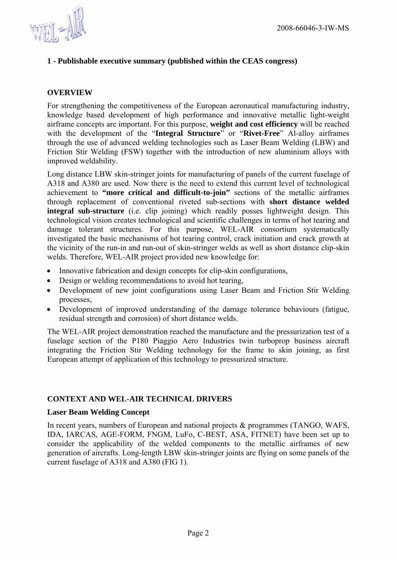
Laser Beam Welding Concept In recent years, numbers of European and national projects & programmes (TANGO, WAFS, IDA, IARCAS, AGE-FORM, FNGM, LuFo, C-BEST, ASA, FITNET) have been set up to consider the applicability of the welded components to the metallic airframes of new generation of aircrafts. Long-length LBW skin-stringer joints are flying on some panels of the current fuselage of A318 and A380 (FIG 1).
2008-66046-3-IW-MS
Page 3
FIG 1. current LBW on A380 (sections 13 and 18, lower fuselage panels 6013 HDT T6 CO2
laser beam welded)
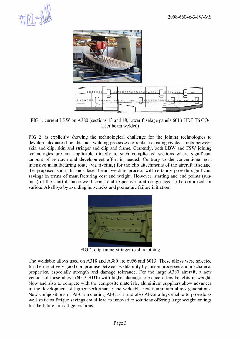
FIG 2. is explicitly showing the technological challenge for the joining technologies to develop adequate short distance welding processes to replace existing riveted joints between skin and clip, skin and stringer and clip and frame. Currently, both LBW and FSW joining technologies are not applicable directly to such complicated sections where significant amount of research and development effort is needed. Contrary to the conventional cost intensive manufacturing route (via riveting) for the clip attachments of the aircraft fuselage, the proposed short distance laser beam welding process will certainly provide significant savings in terms of manufacturing cost and weight. However, starting and end points (run-outs) of the short distance weld seams and respective joint design need to be optimised for various Al-alloys by avoiding hot-cracks and premature failure initiation.
FIG 2. clip-frame-stringer to skin joining
The weldable alloys used on A318 and A380 are 6056 and 6013. These alloys were selected for their relatively good compromise between weldability by fusion processes and mechanical properties, especially strength and damage tolerance. For the large A380 aircraft, a new version of these alloys (6013 HDT) with higher damage tolerance offers benefits in weight. Now and also to compete with the composite materials, aluminium suppliers show advances in the development of higher performance and weldable new aluminium alloys generations. New compositions of Al-Cu including Al-Cu-Li and also Al-Zn alloys enable to provide as well static as fatigue savings could lead to innovative solutions offering large weight savings for the future aircraft generations.
2008-66046-3-IW-MS
Page 4
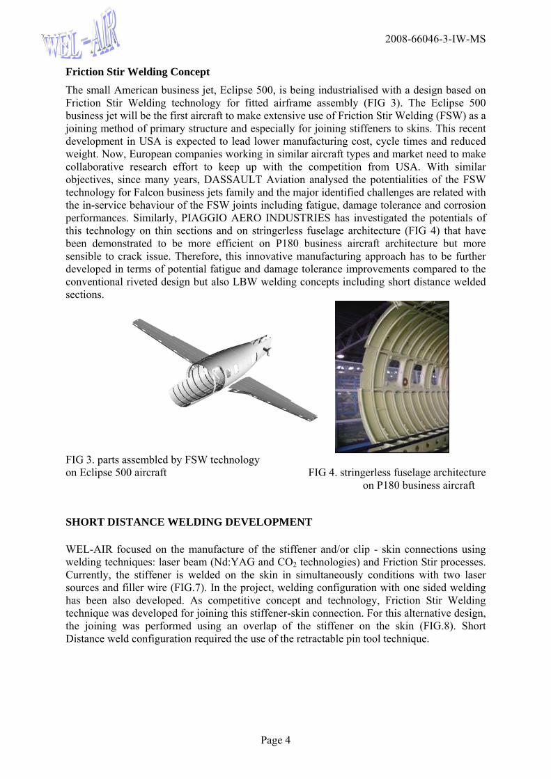
Friction Stir Welding Concept The small American business jet, Eclipse 500, is being industrialised with a design based on Friction Stir Welding technology for fitted airframe assembly (FIG 3). The Eclipse 500 business jet will be the first aircraft to make extensive use of Friction Stir Welding (FSW) as a joining method of primary structure and especially for joining stiffeners to skins. This recent development in USA is expected to lead lower manufacturing cost, cycle times and reduced weight. Now, European companies working in similar aircraft types and market need to make collaborative research effort to keep up with the competition from USA. With similar objectives, since many years, DASSAULT Aviation analysed the potentialities of the FSW technology for Falcon business jets family and the major identified challenges are related with the in-service behaviour of the FSW joints including fatigue, damage tolerance and corrosion performances. Similarly, PIAGGIO AERO INDUSTRIES has investigated the potentials of this technology on thin sections and on stringerless fuselage architecture (FIG 4) that have been demonstrated to be more efficient on P180 business aircraft architecture but more sensible to crack issue. Therefore, this innovative manufacturing approach has to be further developed in terms of potential fatigue and damage tolerance improvements compared to the conventional riveted design but also LBW welding concepts including short distance welded sections.
FIG 3. parts assembled by FSW technology on Eclipse 500 aircraft FIG 4. stringerless fuselage architecture
on P180 business aircraft
SHORT DISTANCE WELDING DEVELOPMENT
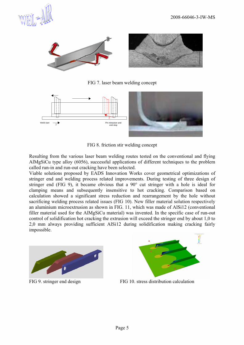
WEL-AIR focused on the manufacture of the stiffener and/or clip - skin connections using welding techniques: laser beam (Nd:YAG and CO2 technologies) and Friction Stir processes. Currently, the stiffener is welded on the skin in simultaneously conditions with two laser sources and filler wire (FIG.7). In the project, welding configuration with one sided welding has been also developed. As competitive concept and technology, Friction Stir Welding technique was developed for joining this stiffener-skin connection. For this alternative design, the joining was performed using an overlap of the stiffener on the skin (FIG.8). Short Distance weld configuration required the use of the retractable pin tool technique.
2008-66046-3-IW-MS
Page 5
FIG 7. laser beam welding concept
FIG 8. friction stir welding concept Resulting from the various laser beam welding routes tested on the conventional and flying AlMgSiCu type alloy (6056), successful applications of different techniques to the problem called run-in and run-out cracking have been selected. Viable solutions proposed by EADS Innovation Works cover geometrical optimizations of stringer end and welding process related improvements. During testing of three design of stringer end (FIG 9), it became obvious that a 90° cut stringer with a hole is ideal for clamping means and subsequently insensitive to hot cracking. Comparison based on calculation showed a significant stress reduction and rearrangement by the hole without sacrificing welding process related issues (FIG 10). New filler material solution respectively an aluminium microextrusion as shown in FIG. 11, which was made of AlSi12 (conventional filler material used for the AlMgSiCu material) was invented. In the specific case of run-out control of solidification hot cracking the extrusion will exceed the stringer end by about 1,0 to 2,0 mm always providing sufficient AlSi12 during solidification making cracking fairly impossible.
FIG 9. stringer end design FIG 10. stress distribution calculation
Weld start Pin retraction and end stop 2
3
2008-66046-3-IW-MS
Page 6
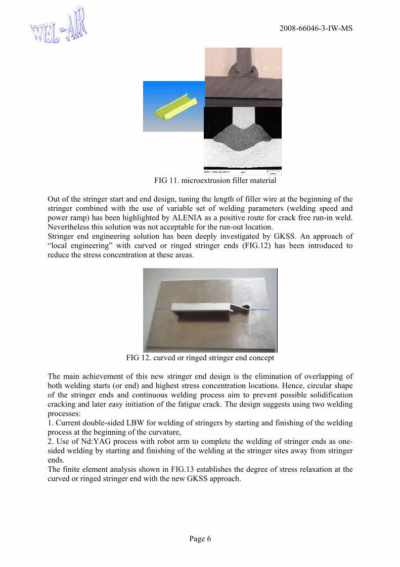
FIG 11. microextrusion filler material
Out of the stringer start and end design, tuning the length of filler wire at the beginning of the stringer combined with the use of variable set of welding parameters (welding speed and power ramp) has been highlighted by ALENIA as a positive route for crack free run-in weld. Nevertheless this solution was not acceptable for the run-out location. Stringer end engineering solution has been deeply investigated by GKSS. An approach of “local engineering” with curved or ringed stringer ends (FIG.12) has been introduced to reduce the stress concentration at these areas.
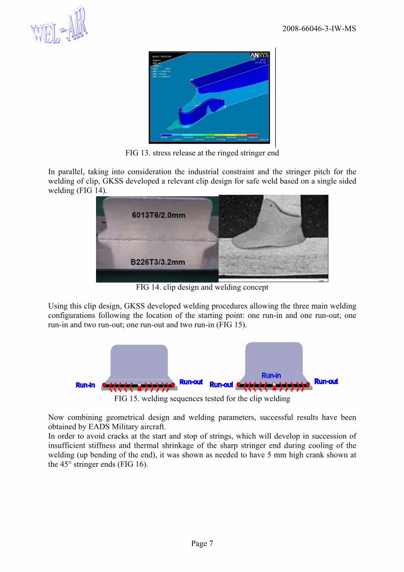
FIG 12. curved or ringed stringer end concept
The main achievement of this new stringer end design is the elimination of overlapping of both welding starts (or end) and highest stress concentration locations. Hence, circular shape of the stringer ends and continuous welding process aim to prevent possible solidification cracking and later easy initiation of the fatigue crack. The design suggests using two welding processes: 1. Current double-sided LBW for welding of stringers by starting and finishing of the welding process at the beginning of the curvature, 2. Use of Nd:YAG process with robot arm to complete the welding of stringer ends as one-sided welding by starting and finishing of the welding at the stringer sites away from stringer ends. The finite element analysis shown in FIG.13 establishes the degree of stress relaxation at the curved or ringed stringer end with the new GKSS approach.
2008-66046-3-IW-MS
Page 7
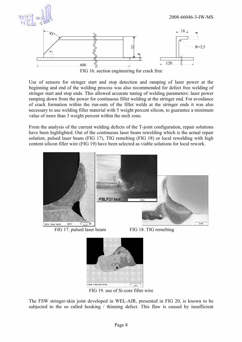
FIG 13. stress release at the ringed stringer end
In parallel, taking into consideration the industrial constraint and the stringer pitch for the welding of clip, GKSS developed a relevant clip design for safe weld based on a single sided welding (FIG 14).
FIG 14. clip design and welding concept
Using this clip design, GKSS developed welding procedures allowing the three main welding configurations following the location of the starting point: one run-in and one run-out; one run-in and two run-out; one run-out and two run-in (FIG 15).
FIG 15. welding sequences tested for the clip welding
Now combining geometrical design and welding parameters, successful results have been obtained by EADS Military aircraft. In order to avoid cracks at the start and stop of strings, which will develop in succession of insufficient stiffness and thermal shrinkage of the sharp stringer end during cooling of the welding (up bending of the end), it was shown as needed to have 5 mm high crank shown at the 45° stringer ends (FIG 16).
2008-66046-3-IW-MS
Page 8
5
32
600
18 4
P hi120
4
45°
R=2,5
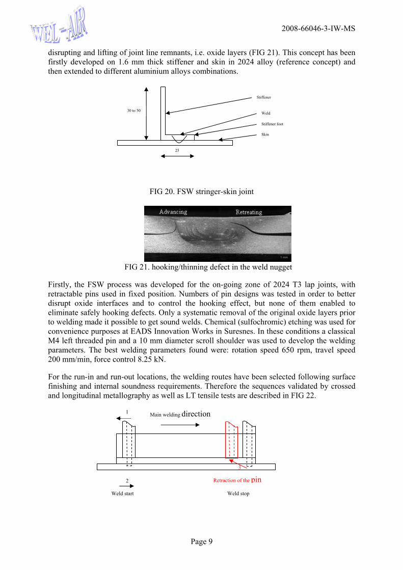
FIG 16. section engineering for crack free
Use of sensors for stringer start and stop detection and ramping of laser power at the beginning and end of the welding process was also recommended for defect free welding of stringer start and stop ends. This allowed accurate tuning of welding parameters: laser power ramping down from the power for continuous fillet welding at the stringer end. For avoidance of crack formation within the run-outs of the fillet welds at the stringer ends it was also necessary to use welding filler material with 5 weight percent silicon, to guarantee a minimum value of more than 3 weight percent within the melt zone. From the analysis of the current welding defects of the T-joint configuration, repair solutions have been highlighted. Out of the continuous laser beam rewelding which is the actual repair solution, pulsed laser beam (FIG 17), TIG remelting (FIG 18) or local rewelding with high content silicon filler wire (FIG 19) have been selected as viable solutions for local rework.
FIG 17. pulsed laser beam FIG 18. TIG remelting
FIG 19. use of Si-core filler wire
The FSW stringer-skin joint developed in WEL-AIR, presented in FIG 20, is known to be subjected to the so called hooking / thinning defect. This flaw is caused by insufficient
2008-66046-3-IW-MS
Page 9
disrupting and lifting of joint line remnants, i.e. oxide layers (FIG 21). This concept has been firstly developed on 1.6 mm thick stiffener and skin in 2024 alloy (reference concept) and then extended to different aluminium alloys combinations.
FIG 20. FSW stringer-skin joint
FIG 21. hooking/thinning defect in the weld nugget
Firstly, the FSW process was developed for the on-going zone of 2024 T3 lap joints, with retractable pins used in fixed position. Numbers of pin designs was tested in order to better disrupt oxide interfaces and to control the hooking effect, but none of them enabled to eliminate safely hooking defects. Only a systematic removal of the original oxide layers prior to welding made it possible to get sound welds. Chemical (sulfochromic) etching was used for convenience purposes at EADS Innovation Works in Suresnes. In these conditions a classical M4 left threaded pin and a 10 mm diameter scroll shoulder was used to develop the welding parameters. The best welding parameters found were: rotation speed 650 rpm, travel speed 200 mm/min, force control 8.25 kN.
For the run-in and run-out locations, the welding routes have been selected following surface finishing and internal soundness requirements. Therefore the sequences validated by crossed and longitudinal metallography as well as LT tensile tests are described in FIG 22.
25
30 to 50
Stiffener
Skin
Weld
Stiffener foot
Main welding direction
Weld start Weld stop
1
2
3
Retraction of the pin
2008-66046-3-IW-MS
Page 10
FIG 22. FSW procedure for run-out control
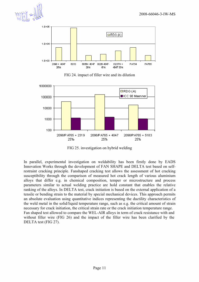
NEW ALLOYS AND JOINT CONFIGURATIONS WEL-AIR aimed at investigating new generation aluminium alloys with expected savings in mechanical performances, static and/or fatigue, and good potential to welding. 2139 T8 and PA734 T79 as skin candidates and PA765 T79 with the 2139 T8 as stiffener candidates were considered as the alternative and higher performance solutions for the stiffener-skin application. The selected skin candidates constitute a high static and damage tolerance alloy (2139) with 20 % savings in static and fatigue crack propagation and comparable fatigue S-N and fracture toughness with respect to the 2056 reference and then the PA734 alloy which provides 15% savings in static with respect to 2056. Finally PA765, stiffener candidate provides 20 % savings in static compared to 2139. The weldability of these new candidates using laser beam process has been investigated through three different approaches. First one aimed at developing and using an analytical approach based on the RDG (Rappaz-Drezet-Gremaud) hot tearing criterion in steady state condition. This analytical tool has been developed by the Computational Materials Laboratory (LSMX, EPF-Lausanne), sub-contractor of EADS Innovation Works. It allowed to classify the WEL-AIR alloys according to their Hot Cracking Susceptibiliy (HCS) without filler wire (FIG 23), to study the influence of the filler material and its dilution on their HCS (FIG 24) and finally to investigate the potential of hybrid welding cases with dissimilar material joining (FIG 25).
FIG 23. hot cracking susceptibility of the parent materials using RDG criterion
Run-inRun-in
2008-66046-3-IW-MS
Page 11
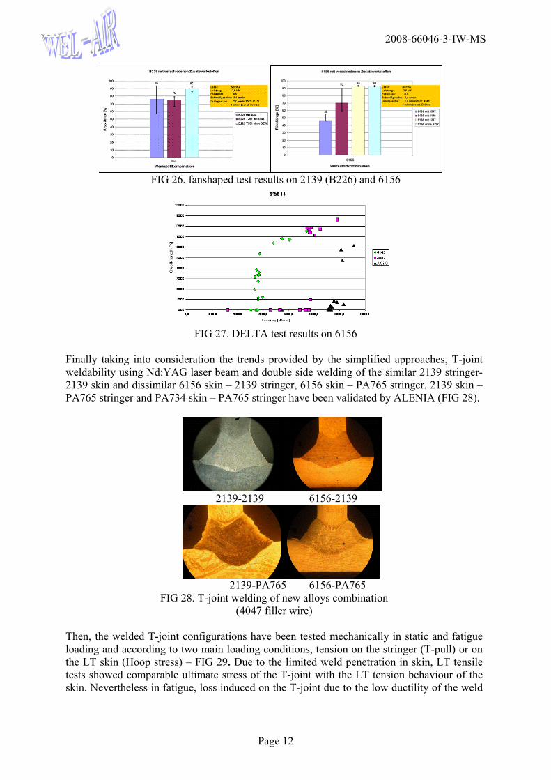
FIG 24. impact of filler wire and its dilution
FIG 25. investigation on hybrid welding
In parallel, experimental investigation on weldability has been firstly done by EADS Innovation Works through the development of FAN SHAPE and DELTA test based on self-restraint cracking principle. Fanshaped cracking test allows the assessment of hot cracking susceptibility through the comparison of measured hot crack length of various aluminium alloys that differ e.g. in chemical composition, temper or microstructure and process parameters similar to actual welding practice are hold constant that enables the relative ranking of the alloys. In DELTA test, crack initiation is based on the external application of a tensile or bending strain to the material by special mechanical devices. This approach permits an absolute evaluation using quantitative indices representing the ductility characteristics of the weld metal in the solid/liquid temperature range, such as e.g. the critical amount of strain necessary for crack initiation, the critical strain rate or the crack initiation temperature range. Fan shaped test allowed to compare the WEL-AIR alloys in term of crack resistance with and without filler wire (FIG 26) and the impact of the filler wire has been clarified by the DELTA test (FIG 27).
2008-66046-3-IW-MS
Page 12
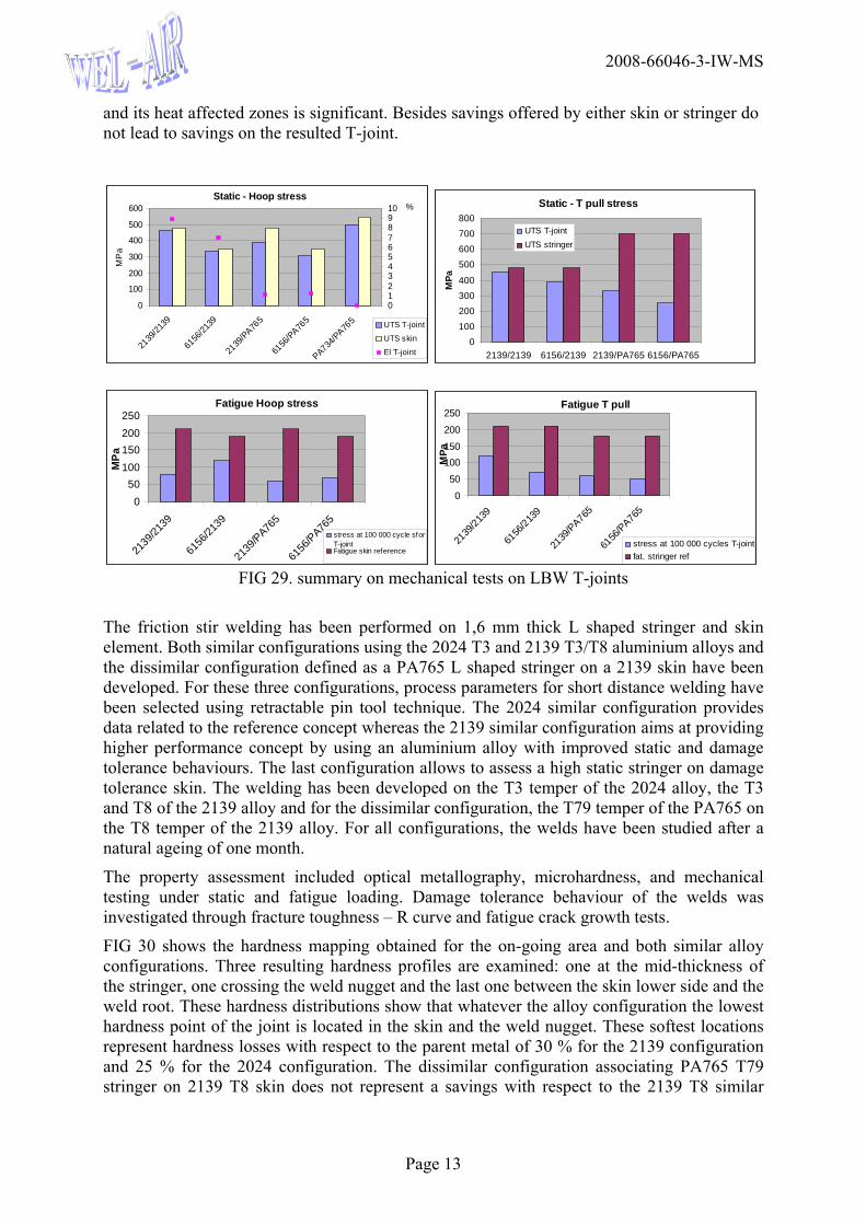
FIG 26. fanshaped test results on 2139 (B226) and 6156
FIG 27. DELTA test results on 6156
Finally taking into consideration the trends provided by the simplified approaches, T-joint weldability using Nd:YAG laser beam and double side welding of the similar 2139 stringer-2139 skin and dissimilar 6156 skin – 2139 stringer, 6156 skin – PA765 stringer, 2139 skin – PA765 stringer and PA734 skin – PA765 stringer have been validated by ALENIA (FIG 28).
2139-2139 6156-2139
2139-PA765 6156-PA765
FIG 28. T-joint welding of new alloys combination (4047 filler wire)
Then, the welded T-joint configurations have been tested mechanically in static and fatigue loading and according to two main loading conditions, tension on the stringer (T-pull) or on the LT skin (Hoop stress) – FIG 29. Due to the limited weld penetration in skin, LT tensile tests showed comparable ultimate stress of the T-joint with the LT tension behaviour of the skin. Nevertheless in fatigue, loss induced on the T-joint due to the low ductility of the weld
2008-66046-3-IW-MS
Page 13
and its heat affected zones is significant. Besides savings offered by either skin or stringer do not lead to savings on the resulted T-joint.
Static - Hoop stress
0
100
200
300
400
500
600
2139
/2139
6156
/2139
2139
/PA765
6156
/PA765
PA734/PA76
5
MP
a
012345678910 %
UTS T-joint
UTS skin
El T-joint
Static - T pull stress
0100200300400
500600700800
2139/2139 6156/2139 2139/PA765 6156/PA765
MPa
UTS T-jointUTS stringer
Fatigue Hoop stress
050
100150200250
2139
/2139
6156
/2139
2139
/PA76
5
6156
/PA76
5
MPa
stress at 100 000 cycle sforT-jointFatigue skin reference
Fatigue T pull
0
50100150
200
250
2139
/2139
6156
/2139
2139
/PA765
6156
/PA765
MPa
stress at 100 000 cycles T-jointfat. stringer ref
FIG 29. summary on mechanical tests on LBW T-joints
The friction stir welding has been performed on 1,6 mm thick L shaped stringer and skin element. Both similar configurations using the 2024 T3 and 2139 T3/T8 aluminium alloys and the dissimilar configuration defined as a PA765 L shaped stringer on a 2139 skin have been developed. For these three configurations, process parameters for short distance welding have been selected using retractable pin tool technique. The 2024 similar configuration provides data related to the reference concept whereas the 2139 similar configuration aims at providing higher performance concept by using an aluminium alloy with improved static and damage tolerance behaviours. The last configuration allows to assess a high static stringer on damage tolerance skin. The welding has been developed on the T3 temper of the 2024 alloy, the T3 and T8 of the 2139 alloy and for the dissimilar configuration, the T79 temper of the PA765 on the T8 temper of the 2139 alloy. For all configurations, the welds have been studied after a natural ageing of one month.
The property assessment included optical metallography, microhardness, and mechanical testing under static and fatigue loading. Damage tolerance behaviour of the welds was investigated through fracture toughness – R curve and fatigue crack growth tests.
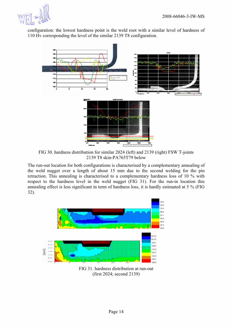
FIG 30 shows the hardness mapping obtained for the on-going area and both similar alloy configurations. Three resulting hardness profiles are examined: one at the mid-thickness of the stringer, one crossing the weld nugget and the last one between the skin lower side and the weld root. These hardness distributions show that whatever the alloy configuration the lowest hardness point of the joint is located in the skin and the weld nugget. These softest locations represent hardness losses with respect to the parent metal of 30 % for the 2139 configuration and 25 % for the 2024 configuration. The dissimilar configuration associating PA765 T79 stringer on 2139 T8 skin does not represent a savings with respect to the 2139 T8 similar
2008-66046-3-IW-MS
Page 14
configuration: the lowest hardness point is the weld root with a similar level of hardness of 110 Hv corresponding the level of the similar 2139 T8 configuration.
FIG 30. hardness distribution for similar 2024 (left) and 2139 (right) FSW T-joints
2139 T8 skin-PA765T79 below
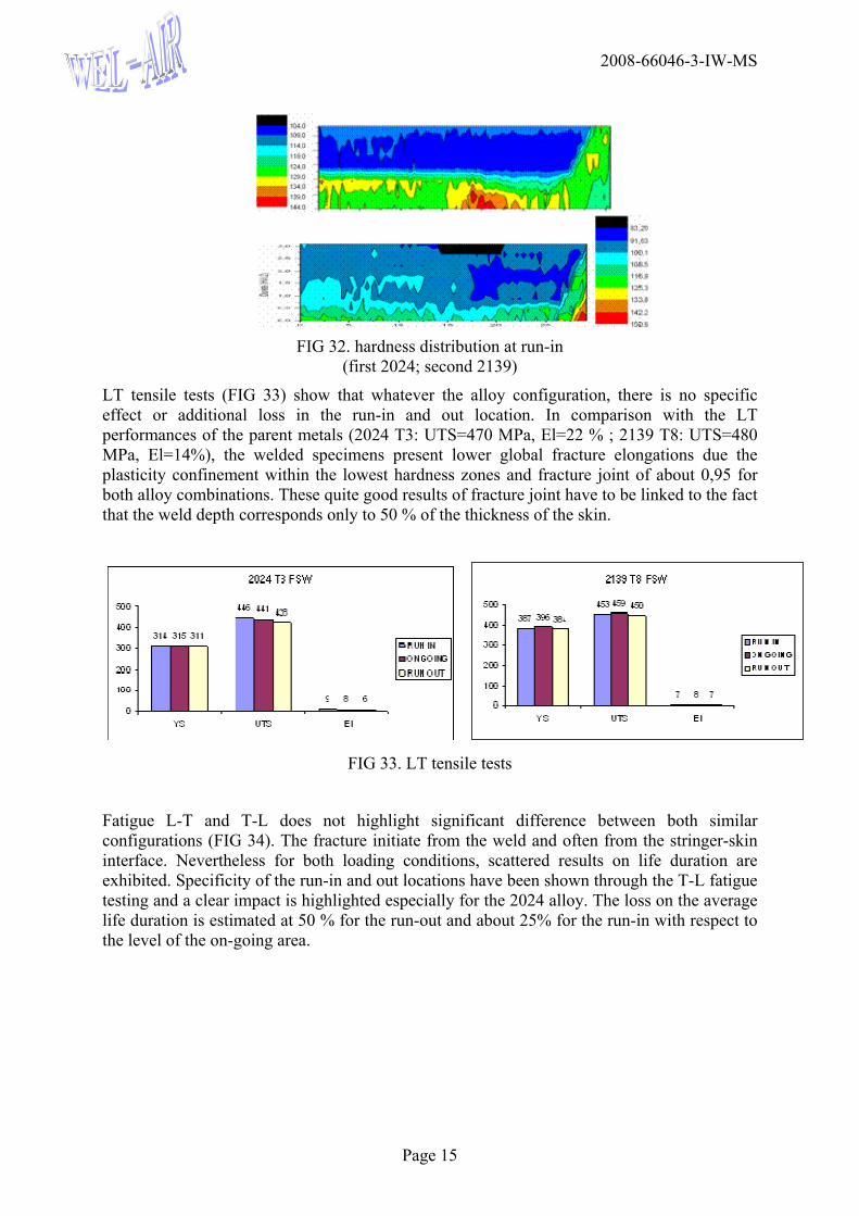
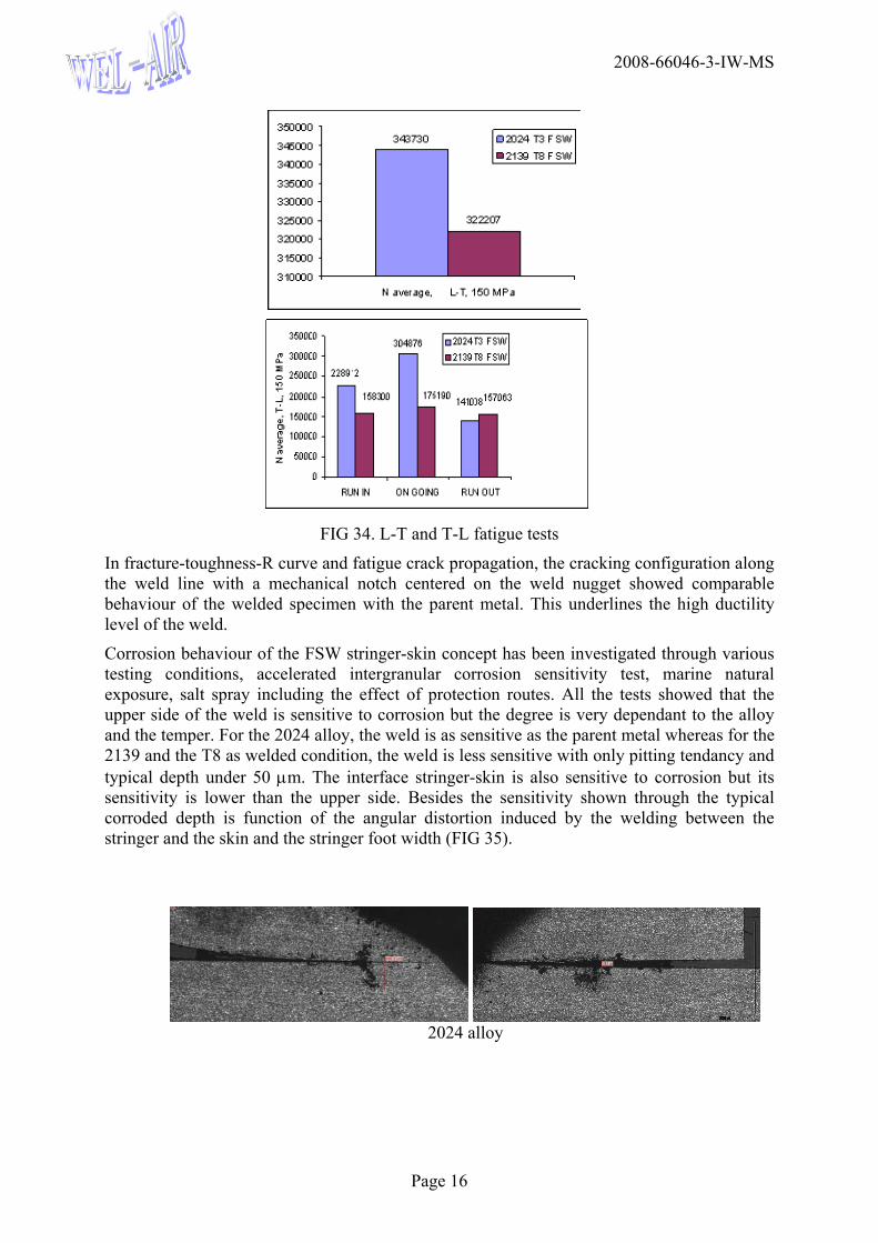
The run-out location for both configurations is characterised by a complementary annealing of the weld nugget over a length of about 15 mm due to the second welding for the pin retraction. This annealing is characterised to a complementary hardness loss of 10 % with respect to the hardness level in the weld nugget (FIG 31). For the run-in location this annealing effect is less significant in term of hardness loss, it is hardly estimated at 5 % (FIG 32).
FIG 31. hardness distribution at run-out
(first 2024; second 2139)
2008-66046-3-IW-MS
Page 15
FIG 32. hardness distribution at run-in
(first 2024; second 2139)
LT tensile tests (FIG 33) show that whatever the alloy configuration, there is no specific effect or additional loss in the run-in and out location. In comparison with the LT performances of the parent metals (2024 T3: UTS=470 MPa, El=22 % ; 2139 T8: UTS=480 MPa, El=14%), the welded specimens present lower global fracture elongations due the plasticity confinement within the lowest hardness zones and fracture joint of about 0,95 for both alloy combinations. These quite good results of fracture joint have to be linked to the fact that the weld depth corresponds only to 50 % of the thickness of the skin.
FIG 33. LT tensile tests
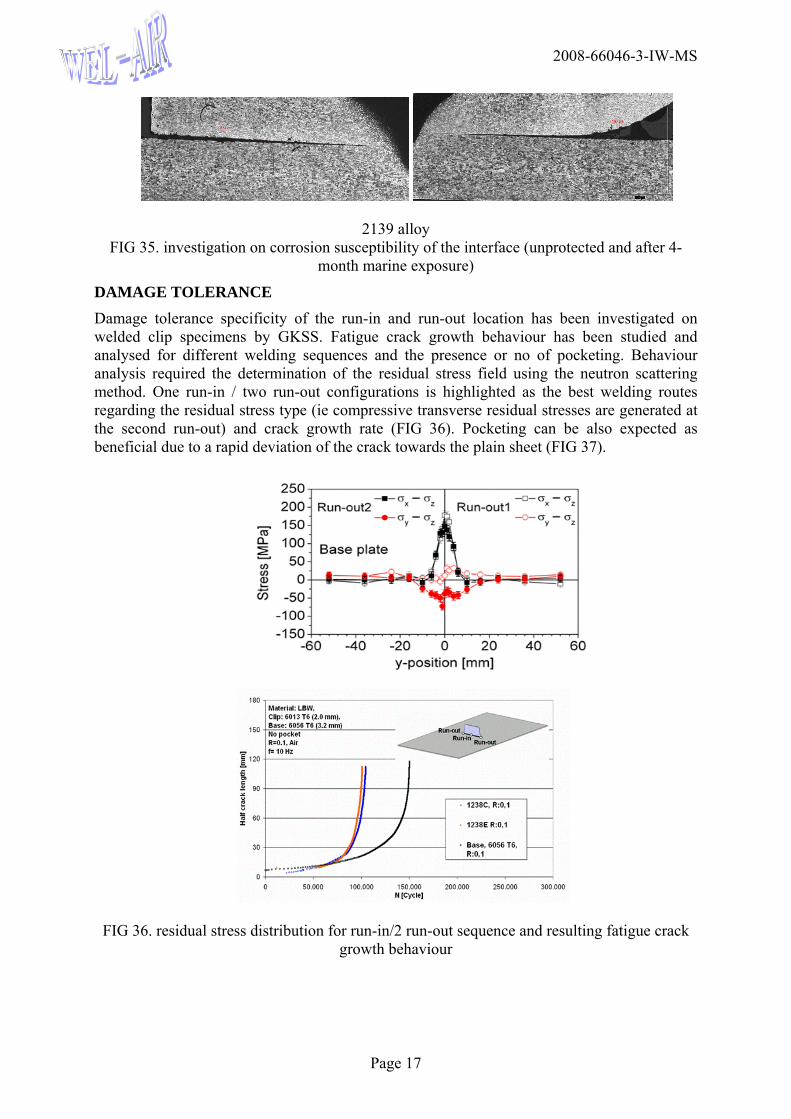
Fatigue L-T and T-L does not highlight significant difference between both similar configurations (FIG 34). The fracture initiate from the weld and often from the stringer-skin interface. Nevertheless for both loading conditions, scattered results on life duration are exhibited. Specificity of the run-in and out locations have been shown through the T-L fatigue testing and a clear impact is highlighted especially for the 2024 alloy. The loss on the average life duration is estimated at 50 % for the run-out and about 25% for the run-in with respect to the level of the on-going area.
2008-66046-3-IW-MS
Page 16
FIG 34. L-T and T-L fatigue tests
In fracture-toughness-R curve and fatigue crack propagation, the cracking configuration along the weld line with a mechanical notch centered on the weld nugget showed comparable behaviour of the welded specimen with the parent metal. This underlines the high ductility level of the weld.
Corrosion behaviour of the FSW stringer-skin concept has been investigated through various testing conditions, accelerated intergranular corrosion sensitivity test, marine natural exposure, salt spray including the effect of protection routes. All the tests showed that the upper side of the weld is sensitive to corrosion but the degree is very dependant to the alloy and the temper. For the 2024 alloy, the weld is as sensitive as the parent metal whereas for the 2139 and the T8 as welded condition, the weld is less sensitive with only pitting tendancy and typical depth under 50 μm. The interface stringer-skin is also sensitive to corrosion but its sensitivity is lower than the upper side. Besides the sensitivity shown through the typical corroded depth is function of the angular distortion induced by the welding between the stringer and the skin and the stringer foot width (FIG 35).
2024 alloy
2008-66046-3-IW-MS
Page 17
2139 alloy FIG 35. investigation on corrosion susceptibility of the interface (unprotected and after 4-
month marine exposure)
DAMAGE TOLERANCE Damage tolerance specificity of the run-in and run-out location has been investigated on welded clip specimens by GKSS. Fatigue crack growth behaviour has been studied and analysed for different welding sequences and the presence or no of pocketing. Behaviour analysis required the determination of the residual stress field using the neutron scattering method. One run-in / two run-out configurations is highlighted as the best welding routes regarding the residual stress type (ie compressive transverse residual stresses are generated at the second run-out) and crack growth rate (FIG 36). Pocketing can be also expected as beneficial due to a rapid deviation of the crack towards the plain sheet (FIG 37).
FIG 36. residual stress distribution for run-in/2 run-out sequence and resulting fatigue crack growth behaviour
2008-66046-3-IW-MS
Page 18
FIG 37. deviation of the crack from the weld area
due to pocketing
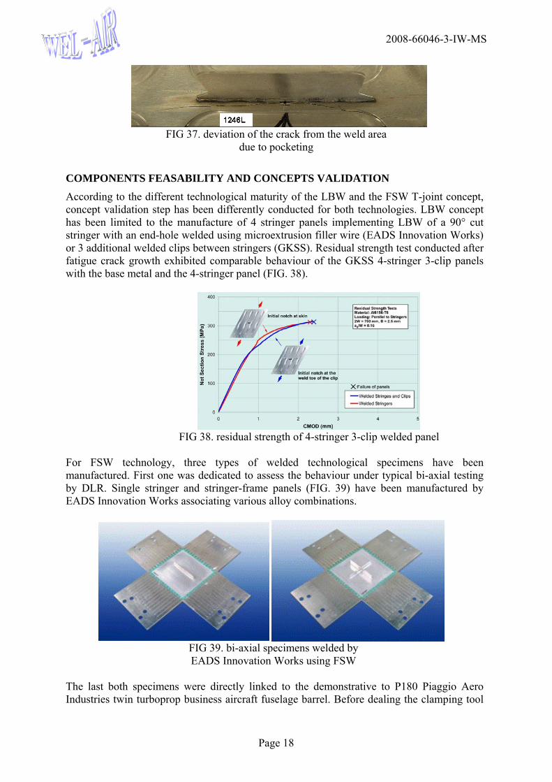
COMPONENTS FEASABILITY AND CONCEPTS VALIDATION According to the different technological maturity of the LBW and the FSW T-joint concept, concept validation step has been differently conducted for both technologies. LBW concept has been limited to the manufacture of 4 stringer panels implementing LBW of a 90° cut stringer with an end-hole welded using microextrusion filler wire (EADS Innovation Works) or 3 additional welded clips between stringers (GKSS). Residual strength test conducted after fatigue crack growth exhibited comparable behaviour of the GKSS 4-stringer 3-clip panels with the base metal and the 4-stringer panel (FIG. 38).
FIG 38. residual strength of 4-stringer 3-clip welded panel
For FSW technology, three types of welded technological specimens have been manufactured. First one was dedicated to assess the behaviour under typical bi-axial testing by DLR. Single stringer and stringer-frame panels (FIG. 39) have been manufactured by EADS Innovation Works associating various alloy combinations.
FIG 39. bi-axial specimens welded by EADS Innovation Works using FSW
The last both specimens were directly linked to the demonstrative to P180 Piaggio Aero Industries twin turboprop business aircraft fuselage barrel. Before dealing the clamping tool
2008-66046-3-IW-MS
Page 19
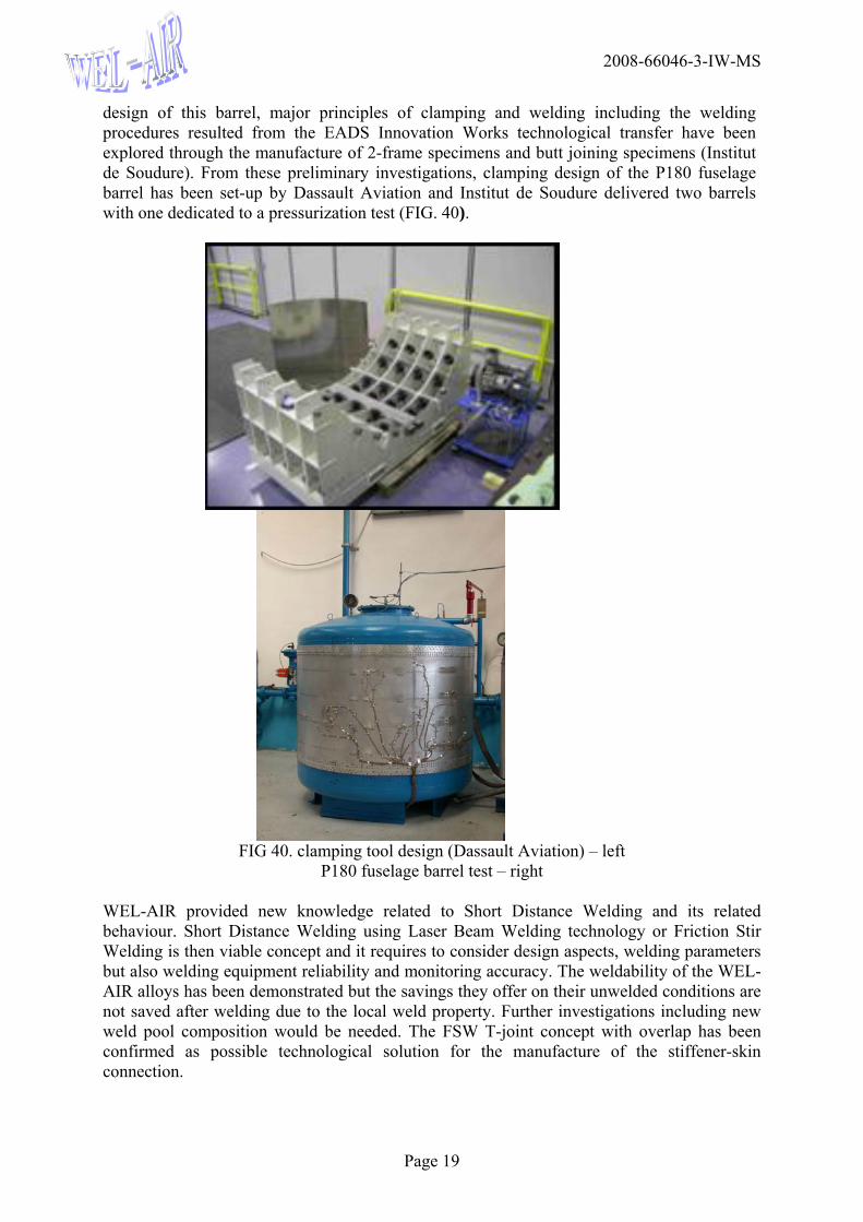
design of this barrel, major principles of clamping and welding including the welding procedures resulted from the EADS Innovation Works technological transfer have been explored through the manufacture of 2-frame specimens and butt joining specimens (Institut de Soudure). From these preliminary investigations, clamping design of the P180 fuselage barrel has been set-up by Dassault Aviation and Institut de Soudure delivered two barrels with one dedicated to a pressurization test (FIG. 40).
FIG 40. clamping tool design (Dassault Aviation) – left
P180 fuselage barrel test – right WEL-AIR provided new knowledge related to Short Distance Welding and its related behaviour. Short Distance Welding using Laser Beam Welding technology or Friction Stir Welding is then viable concept and it requires to consider design aspects, welding parameters but also welding equipment reliability and monitoring accuracy. The weldability of the WEL-AIR alloys has been demonstrated but the savings they offer on their unwelded conditions are not saved after welding due to the local weld property. Further investigations including new weld pool composition would be needed. The FSW T-joint concept with overlap has been confirmed as possible technological solution for the manufacture of the stiffener-skin connection.
Related Documents