Fibre Channel SAN Topologies Version 2.1 • Fibre Channel Topology Overview • Simple and Complex Fibre Channel SAN Topologies • Brocade Virtual Fabrics and EMC RecoverPoint Case Studies • FICON Topologies Erik Smith Aditya Nadkarni Richard Hultman Dennis Kloepping

Fibre Channel SAN Topologies
May 13, 2015
This EMC Engineering TechBook provides a high-level overview of Fibre Channel SAN topologies, discusses simple and complex Fibre Channel SAN topologies, and provides case studies for Brocade Virtual Fabrics and EMC RecoverPoint. FICON connectivity is also discussed.
Welcome message from author
This document is posted to help you gain knowledge. Please leave a comment to let me know what you think about it! Share it to your friends and learn new things together.
Transcript
Fibre Channel SAN Topologies
Version 2.1
• Fibre Channel Topology Overview
• Simple and Complex Fibre Channel SAN Topologies
• Brocade Virtual Fabrics and EMC RecoverPoint Case Studies
• FICON Topologies
Erik SmithAditya NadkarniRichard HultmanDennis Kloepping

Fibre Channel SAN Topologies TechBook2
Copyright © 2011 EMC Corporation. All rights reserved.
EMC believes the information in this publication is accurate as of its publication date. The information is subject to change without notice.
THE INFORMATION IN THIS PUBLICATION IS PROVIDED “AS IS.” EMC CORPORATION MAKES NO REPRESENTATIONS OR WARRANTIES OF ANY KIND WITH RESPECT TO THE INFORMATION IN THIS PUBLICATION, AND SPECIFICALLY DISCLAIMS IMPLIED WARRANTIES OF MERCHANTABILITY OR FITNESS FOR A PARTICULAR PURPOSE.
Use, copying, and distribution of any EMC software described in this publication requires an applicable software license.
For the most up-to-date regulatory document for your product line, go to the Technical Documentation and Advisories section on EMC Powerlink.
For the most up-to-date listing of EMC product names, see EMC Corporation Trademarks on EMC.com.
All other trademarks used herein are the property of their respective owners.
Part number H8074.3
Contents
Preface............................................................................................................................ 13
Chapter 1 Fibre Channel SAN TopologiesFibre Channel topology overview.................................................. 20Instructions for using this TechBook.............................................. 21Best practices ..................................................................................... 23
Connectrix B ............................................................................... 26Zoning ......................................................................................... 27ISL trunking................................................................................ 28Connectrix MDS......................................................................... 28Connectrix M.............................................................................. 29QLogic ......................................................................................... 29Host and storage layout............................................................ 30
Switch and fabric management ...................................................... 32Connectrix B ............................................................................... 32Connectrix MDS......................................................................... 34Connectrix M.............................................................................. 34QLogic ......................................................................................... 35
Security ............................................................................................... 36Connectrix B ............................................................................... 36Connectrix MDS......................................................................... 37Connectrix M.............................................................................. 37QLogic ......................................................................................... 37
Fibre Channel SAN Topologies TechBook 3
Contents
Chapter 2 Simple Fibre Channel SAN TopologiesSingle switch fabrics ......................................................................... 40
Overview of fabric design considerations ............................. 40Connectrix B example ............................................................... 41Connectrix MDS example......................................................... 44Connectrix M example.............................................................. 52QLogic example ......................................................................... 61
Two switch fabrics ............................................................................ 69Overview of fabric design considerations ............................. 69Connectrix B example ............................................................... 71Connectrix MDS example......................................................... 82Connectrix M example.............................................................. 91QLogic example ....................................................................... 108
Blade switch with direct attached storage .................................. 120General steps to set up a blade server .................................. 121Best practices ............................................................................ 124Host and storage layout ......................................................... 125Switch and fabric management ............................................. 125Security ..................................................................................... 126IBM Brocade example ............................................................. 127
Chapter 3 Complex Fibre Channel SAN TopologiesBest practices ................................................................................... 138
ISL subscription ....................................................................... 138Host and storage layout ......................................................... 138Switch and fabric management ............................................. 138Security ..................................................................................... 138
Four switch full mesh..................................................................... 139Overview of Fabric Design considerations.......................... 139Connectrix B example ............................................................. 140Connectrix MDS example....................................................... 151Connectrix M example............................................................ 163QLogic example ....................................................................... 181
Compound core edge switches..................................................... 192Overview of fabric design considerations ........................... 192Connectrix B example ............................................................. 194Connectrix MDS example....................................................... 211Connectrix M example............................................................ 227
Heterogeneous switch interoperability ....................................... 250Interoperability overview....................................................... 250Heterogeneous SAN design................................................... 253
Fibre Channel SAN Topologies TechBook4
Contents
How to set up an interoperable switched fabric topology.................................................................................. 253
Cisco Inter VSAN Routing (IVR) in a heterogeneous environment.............................................................................. 347Vendor-specific switch settings for interop ......................... 351Heterogeneous interoperability test information................ 359
Distance extension case studies .................................................... 362Case study #1: Configuring an MP-1620M running
EOSi 5.1................................................................................... 362Case study #2: FCIP configuration and setup...................... 390
Chapter 4 Monitoring your SANIntroduction ..................................................................................... 400Switch-based error types................................................................ 402Fabric resiliency features and recommendations ....................... 408
Brocade SAN resiliency features ........................................... 408Fabric resiliency thresholds.................................................... 410Quick reference for steps to address switch-based errors issues.......................................................................................... 411
Brocade fabric resiliency concepts ................................................ 416Latency and congestion bottleneck conditions.................... 416Latency severities..................................................................... 419Latency detection, notification, isolation, and
mitigation .............................................................................. 420Configuring FS features case study .............................................. 423
Case study: Brocade CLI and CMDCE ................................. 423Configuring Bottleneck Detection ......................................... 427Enabling port fencing .............................................................. 431Configuring Edge Hold Time ................................................ 436
Summary .......................................................................................... 438
Chapter 5 Brocade Virtual Fabrics Case StudyBrocade Virtual Fabrics case study overview ............................. 440Objectives of Virtual Fabrics architecture .................................... 441Logical Switch capability ............................................................... 442Virtual Fabrics and ISLs ................................................................. 445How to configure Brocade Virtual Fabrics case study............... 448Brocade Virtual Fabrics versus traditional Cisco Virtual
SANs .............................................................................................. 466
5Fibre Channel SAN Topologies TechBook
Contents
Chapter 6 EMC RecoverPoint Case StudyRecoverPoint case study overview .............................................. 472
Configuration overview ......................................................... 472RecoverPoint concepts............................................................ 474RecoverPoint components...................................................... 475RecoverPoint installation prerequisites ............................... 477Phase 1: Base configuration of Connectrix B series
fabric....................................................................................... 486Phase 2: Add and configure Connectrix AP-7600B
application services platform.............................................. 487Phase 3: Add second AP-7600B to Fabric B ......................... 502Phase 4: Add and configure RecoverPoint Appliance
(RPA) ...................................................................................... 503Phase 5: Configure recovery site Connectrix AP-7600B
and RPA ................................................................................. 524Phase 6: Configure RecoverPoint volumes and services ... 531Phase 7: Start replication ........................................................ 551Phase 8: Confirm replication is running .............................. 553
Implementing a scalable core-edge topology ............................. 554Overview of scalable core-edge architecture....................... 554Scalable core-edge fabric design............................................ 554Scalable core-edge ................................................................... 557
Chapter 7 FICON TopologiesOverview.......................................................................................... 580Topology support............................................................................ 582Zoning practices.............................................................................. 583Cascading......................................................................................... 584Terminology..................................................................................... 585IOCP considerations....................................................................... 587FICON and EMC Ionix ControlCenter ........................................ 589CUP (fabric management server) ................................................. 590Connectrix B series ......................................................................... 591
Supported products ................................................................ 591Configuring .............................................................................. 591OCP considerations................................................................. 592CUP support............................................................................. 592Switch node identifier............................................................. 593EMC documentation ............................................................... 593
Connectrix M series ........................................................................ 594Supported products ................................................................ 594Configuring .............................................................................. 594
Fibre Channel SAN Topologies TechBook6
Contents
IOCP configuration.................................................................. 595Distance options....................................................................... 597SANtegrity ................................................................................ 598Address swapping ................................................................... 598CUP ............................................................................................ 599
Connectrix MDS series ................................................................... 600Supported products ................................................................. 600Requirements............................................................................ 600Configuring............................................................................... 601OCP considerations ................................................................. 602CUP support ............................................................................. 602FICON configuration files ...................................................... 602Switch node identifier ............................................................. 603FICON port numbering .......................................................... 604References ................................................................................. 605
Glossary........................................................................................................................ 607
Index .............................................................................................................................. 629
7Fibre Channel SAN Topologies TechBook

Contents
Fibre Channel SAN Topologies TechBook8
Title Page
Figures
1 Single switch topology example .................................................................. 402 Single switch SAN using DS-4100B and EZSwitchSetup with zoning ... 413 Connectrix MDS 9506 using VSANs ........................................................... 444 Single switch fabric built with a DS-4700M ................................................ 525 Single switch fabric built with QLogic SB5602 .......................................... 616 Two switch fabric example ........................................................................... 697 Two switch SAN with DS-4100B and DS-4900B using CLI to
configure SAN ..................................................................................................718 Port settings ..................................................................................................... 789 Two Connectrix MDS 9506s using VSANs ................................................. 8210 Two ED-10000Ms using virtual switches .................................................... 9211 Connection Description dialog box ............................................................. 9612 Two SB5602 switches using Quicktools .................................................... 10813 (a) Blade server direct attached to storage (b) two-tier FC SAN ........... 12114 IBM blade server directly attached to storage ......................................... 12715 IBM Brocade 4 GB SAN switch module (32R1812) directly attached
to storage .........................................................................................................12816 Four switch full mesh fabric ....................................................................... 13917 Four switch fabric with ED-48000Bs .......................................................... 14118 Four Connectrix MDS 9506s full mesh configuration ............................. 15119 Four ED-140Ms full mesh configuration .................................................. 16320 Four SB9000s in full mesh configuration .................................................. 18121 Four switch compound core edge switches ............................................. 19222 Four ED-48000Bs in full mesh configuration with edge switches
attached............................................................................................................19423 Four MDS 9513s in full mesh configuration with edge switches
attached............................................................................................................21124 Four ED-10000Ms in full mesh configuration with edge switches
attached............................................................................................................22725 Connection description dialog box ............................................................ 232
Fibre Channel SAN Topologies TechBook 9
Figures
26 Phase 1: Basic configuration topology ...................................................... 25627 Phase 2: Adding Connectrix MDS 9513 .................................................... 25828 Phase 3: Moving half of host and storage ports ....................................... 26229 Phase 4: Complete moving host and storage ports ................................. 26330 Phase 5: Adding Connectrix MDS 9216 .................................................... 26431 Phase 6: Moving hosts and storage to new edge ..................................... 26532 Phase 7: Adding Connectrix MDS switch to the core ............................. 26633 Phase 1: Base configuration ........................................................................ 26934 Phase 2: Adding Connectrix MDS 9513 to the core of the fabric .......... 27435 Phase 3: Moving half the hosts and storage ports ................................... 27736 Phase 4: Completely moving host and storage ports .............................. 27837 Phase 5: Adding Connectrix MDS 9216 .................................................... 27938 Phase 6 topology .......................................................................................... 28139 Phase 7 topology .......................................................................................... 28240 Phase 1: Basic configuration ....................................................................... 28541 Phase 2: Adding Connectrix MDS 9513 .................................................... 28742 Phase 3: Moving half the host and storage ports ..................................... 29043 Phase 4: Completely moving host and storage ports .............................. 29144 Phase 5: Adding Connectrix MDS 9216 .................................................... 29245 Phase 6: Moving hosts and storage to a new edge .................................. 29446 Phase 7: Adding Connectrix M switch to core example ......................... 29547 Phase 1: Basic configuration ....................................................................... 29848 Phase 2: Adding Connectrix MDS 9513 .................................................... 30149 Phase 3: Moving half the host and storage ports ..................................... 30450 Phase 4: Completely moving host and storage ports .............................. 30551 Phase 5: Adding Connectrix MDS 9216 .................................................... 30652 Phase 6: Moving hosts and storage to a new edge .................................. 30853 Phase 7: Adding Connectrix M switch to the core .................................. 30954 Phase 1: Basic configuration ....................................................................... 31255 Phase 2: Adding ED-24000B ....................................................................... 31456 Phase 3: Moving half the host and storage ports ..................................... 31657 Phase 4: Completely moving host and storage ports .............................. 31758 Phase 5: Adding DS-16B2 and DS-220B .................................................... 31859 Phase 6: Moving hosts and storage to the new edge switches .............. 32060 Phase 7: Adding Connectrix B switch ....................................................... 32161 Donor and target topology ......................................................................... 32462 Phase 1: Basic configuration of Connectrix M fabric .............................. 32663 Phase 2: Adding Connectrix B fabric and SAN router ........................... 32864 Phase 3: Configuring Connectrix B SAN routing .................................... 33065 Phase 4: Moving half of the host and storage ports ................................ 34366 Phase 5: Complete moving host and storage ports in the core ............. 34667 Topology environment ................................................................................ 36568 Output example ............................................................................................ 373
Fibre Channel SAN Topologies TechBook10
Figures
69 Portion of environment displayed by Show Fabric topology command .........................................................................................................373
70 Site 1 Worksheet ........................................................................................... 38671 Site 2 Worksheet ........................................................................................... 38772 Completed Site 1 Worksheet ....................................................................... 38873 Completed Site 2 Worksheet ....................................................................... 38974 FCIP Target environment ............................................................................ 39075 Site 1 Worksheet ........................................................................................... 39476 Site 2 Worksheet ........................................................................................... 39577 Completed Site 1 Worksheet ....................................................................... 39678 Completed Site 2 Worksheet ....................................................................... 39779 Fabric wide effects of a latency bottleneck condition .............................. 41780 Fabric wide effects of a congestion bottleneck condition ....................... 41881 Uncongested environment .......................................................................... 42482 Impact of a slow drain port ......................................................................... 42583 Buffer Queue for port 7 continues to grow ............................................... 42684 Bufferl Queue for port 7 on Switch A, port 1 ........................................... 42785 Port fencing dialog box ................................................................................ 43386 Port Fencing dialog box ............................................................................... 43487 Create a customized threshold ................................................................... 43588 Apply customized threshold ...................................................................... 43589 Logical Switches ........................................................................................... 44290 DISL connections between Logical Switches ............................................ 44591 ISL connection between Logical Switches and non-VF-capable
switch ...............................................................................................................44692 XISL connection between Base Switches (BS) .......................................... 44793 Topology A example .................................................................................... 44894 Topology B example ..................................................................................... 44995 Block diagram of fabric topology ............................................................... 45996 Base configuration of Connectrix B Fabric ................................................ 48697 Adding AP-7600B Application Services Platform to Fabric A ............... 48798 Three new zones used with RecoverPoint ................................................ 49899 Configuration of Fabric B ............................................................................ 502100 Adding RecoverPoint Appliances (RPA) .................................................. 503101 Final configuration with recovery site added .......................................... 524102 Topology for RecoverPoint configuration ................................................ 532103 Phase 1 – Single core scales by adding edge switches and port
blades................................................................................................................555104 Phase 2 – Expanded single core-edge, Expanding the core ................... 556105 Phase 3 – Expanded core-edge ................................................................... 557106 Host Connectivity Manager window ........................................................ 575
11Fibre Channel SAN Topologies TechBook
Figures
107 EMC PowerPath window ........................................................................... 576108 View All window ......................................................................................... 577109 Cascaded IOCP ............................................................................................. 587110 Cascaded FICON IOCP ............................................................................... 587
Fibre Channel SAN Topologies TechBook12
Preface
This EMC Engineering TechBook provides a high-level overview of Fibre Channel SAN topologies, discusses simple and complex Fibre Channel SAN topologies, shows how to monitor your SAN, and provides case studies for Brocade Virtual Fabrics and EMC RecoverPoint. FICON connectivity is also discussed.
E-Lab would like to thank all the contributors to this document, including EMC engineers, EMC field personnel, and partners. Your contributions are invaluable.
As part of an effort to improve and enhance the performance and capabilities of its product lines, EMC periodically releases revisions of its hardware and software. Therefore, some functions described in this document may not be supported by all versions of the software or hardware currently in use. For the most up-to-date information on product features, refer to your product release notes. If a product does not function properly or does not function as described in this document, please contact your EMC representative.
Audience This TechBook is intended for EMC field personnel, including technology consultants, and for the storage architect, administrator, and operator involved in acquiring, managing, operating, or designing a networked storage environment that contains EMC and host devices.
EMC Support Matrixand E-Lab
InteroperabilityNavigator
For the most up-to-date information, always consult the EMC Support Matrix (ESM), available through E-Lab Interoperability Navigator (ELN) at http://elabnavigator.EMC.com, under the PDFs and Guides tab.
The EMC Support Matrix links within this document will take you to Powerlink where you are asked to log in to the E-Lab Interoperability
Fibre Channel SAN Topologies TechBook 13
14
Preface
Navigator. Instructions on how to best use the ELN (tutorial, queries, wizards) are provided below this Log in window. If you are unfamiliar with finding information on this site, please read these instructions before proceeding any further.
Under the PDFs and Guides tab resides a collection of printable resources for reference or download. All of the matrices, including the ESM (which does not include most software), are subsets of the E-Lab Interoperability Navigator database. Included under this tab are:
◆ The EMC Support Matrix, a complete guide to interoperable, and supportable, configurations.
◆ Subset matrices for specific storage families, server families, operating systems or software product.
◆ Host connectivity guides for complete, authoritative information on how to configure hosts effectively for various storage environments.
Under the PDFs and Guides tab, consult the Internet Protocol pdf under the "Miscellaneous" heading for EMC's policies and requirements for the EMC Support Matrix.
Relateddocumentation
Related documents include:
◆ The former EMC Networked Storage Topology Guide has been divided into several TechBooks and reference manuals. The following documents, including this one, are available through the E-Lab Interoperability Navigator, Topology Resource Center tab, at http://elabnavigator.EMC.com.
These documents are also available at the following location:
http://www.emc.com/products/interoperability/topology-resource-center.htm
• Backup and Recovery in a SAN TechBook
• Building Secure SANs TechBook
• Extended Distance Technologies TechBook
• Fibre Channel over Ethernet (FCoE): Data Center Bridging (DCB) Concepts and Protocols TechBook
• iSCSI SAN Topologies TechBook
• Networked Storage Concepts and Protocols TechBook
• Networking for Storage Virtualization and RecoverPoint TechBook
• WAN Optimization Controller Technologies TechBook
Fibre Channel SAN Topologies TechBook
Preface
• EMC Connectrix SAN Products Data Reference Manual
• Legacy SAN Technologies Reference Manual
• Non-EMC SAN Products Data Reference Manual
◆ RSA security solutions documentation, which can be found at http://RSA.com > Content Library
All of the following documentation and release notes can be found at http://Powerlink.EMC.com. From the toolbar, select Support > Technical Documentation and Advisories, then choose the appropriate Hardware/Platforms, Software, or Host Connectivity/HBAs documentation links.
Hardware documents and release notes include those on:
◆ Connectrix B series ◆ Connectrix M series ◆ Connectrix MDS (release notes only)◆ VNX series◆ CLARiiON ◆ Celerra ◆ Symmetrix
Software documents include those on:
◆ EMC Ionix ControlCenter ◆ RecoverPoint ◆ Invista ◆ TimeFinder ◆ PowerPath
The following E-Lab documentation is also available:
◆ Host Connectivity Guides◆ HBA Guides
For Cisco and Brocade documentation, refer to the vendor’s website.
◆ http://cisco.com
◆ http://brocade.com
Authors of thisTechBook
This TechBook was authored by Erik Smith, Aditya Nadkarni, Richard Hultman, and Dennis Kloepping, with contributions from EMC employees, EMC engineers, EMC field personnel, and partners.
Fibre Channel SAN Topologies TechBook 15
16
Preface
Erik Smith is a Consultant Systems Integration Engineer and has been with EMC for over 13 years. For the past 6 years, Erik has worked in the E-Lab qualifying new FC switch hardware, firmware, and management application revisions, in addition to being a major contributor to the Topology Guide. Erik is one of the founding members of the original SAN team in Technical Support. Erik is a member of T11.
Aditya Nadkarni is a a Senior Systems Integration Engineer and has been working with EMC's E-Lab for over 6 years. Aditya qualifies new Brocade-based FC switch hardware, firmware, and management application. In addition, Adi is involved in multi-vendor switch interoperability and blade server embedded module qualification projects which cover FC switch modules, pass-through modules, NPIV gateways and, more recently, the FCoE-based convergence modules.
Richard Hultman is a Consultant Systems Integration Engineer and has been with EMC for over 13 years. For the past 10 years, Rich has worked in the E-Lab qualifying switch firmware and hardware. Rich has over 30 years of experience including designing personal computer hardware, symmetric multi-processing systems, and disk adapters, as well as developing firmware for disk controllers.
Dennis Kloepping is a a Principal Integration Engineer in EMC's E-Lab Product Certification and Test group. Dennis has been with EMC for over 11 years, focusing on IBM zSeries FICON interconnectivity with EMC products. He is involved with the EMC/IBM zSeries relationship, exchanging early ship features and microcode between both companies and joint customer escalations. Prior to EMC, Dennis worked at IBM for over 21 years, concentrating on IBM mainframe support.
Conventions used inthis document
EMC uses the following conventions for special notices:
IMPORTANT!An important notice contains information essential to software or hardware operation.
Note: A note presents information that is important, but not hazard-related.
Fibre Channel SAN Topologies TechBook
Preface
Typographical conventionsEMC uses the following type style conventions in this document.
Normal Used in running (nonprocedural) text for:• Names of interface elements (such as names of windows,
dialog boxes, buttons, fields, and menus)• Names of resources, attributes, pools, Boolean expressions,
buttons, DQL statements, keywords, clauses, environment variables, functions, utilities
• URLs, pathnames, filenames, directory names, computer names, filenames, links, groups, service keys, file systems, notifications
Bold Used in running (nonprocedural) text for:• Names of commands, daemons, options, programs,
processes, services, applications, utilities, kernels, notifications, system calls, man pages
Used in procedures for:• Names of interface elements (such as names of windows,
dialog boxes, buttons, fields, and menus)• What user specifically selects, clicks, presses, or types
Italic Used in all text (including procedures) for:• Full titles of publications referenced in text• Emphasis (for example a new term)• Variables
Courier Used for:• System output, such as an error message or script • URLs, complete paths, filenames, prompts, and syntax when
shown outside of running text
Courier bold Used for:• Specific user input (such as commands)
Courier italic Used in procedures for:• Variables on command line• User input variables
< > Angle brackets enclose parameter or variable values supplied by the user
[ ] Square brackets enclose optional values
| Vertical bar indicates alternate selections - the bar means “or”
{ } Braces indicate content that you must specify (that is, x or y or z)
... Ellipses indicate nonessential information omitted from the example
Fibre Channel SAN Topologies TechBook 17
18
Preface
Where to get help EMC support, product, and licensing information can be obtained as follows.
Product information — For documentation, release notes, software updates, or for information about EMC products, licensing, and service, go to the EMC Powerlink website (registration required) at:
http://Powerlink.EMC.com
Technical support — For technical support, go to Powerlink and choose Support. On the Support page, you will see several options, including one for making a service request. Note that to open a service request, you must have a valid support agreement. Please contact your EMC sales representative for details about obtaining a valid support agreement or with questions about your account.
We'd like to hear from you!
Your feedback on our TechBooks is important to us! We want our books to be as helpful and relevant as possible, so please feel free to send us your comments, opinions and thoughts on this or any other TechBook:
Fibre Channel SAN Topologies TechBook

1Invisible Body Tag
This chapter provides an overview of Fibre Channel SAN topologies.
◆ Fibre Channel topology overview ................................................... 20◆ Instructions for using this TechBook............................................... 21◆ Best practices....................................................................................... 23◆ Switch and fabric management........................................................ 32◆ Security ................................................................................................ 36
Fibre Channel SANTopologies
Fibre Channel SAN Topologies 19
20
Fibre Channel SAN Topologies
Fibre Channel topology overviewThis chapter provides information on Fibre Channel SAN topologies.
For valuable information that may be helpful prior to building a SAN, refer to the Networked Storage Concepts and Protocols TechBook, available through the E-Lab Interoperability Navigator, Topology Resource Center tab, at http://elabnavigator.EMC.com.
For purposes of this document, EMC® E-Lab™ uses the following definitions for simple and complex SANs:
◆ A simple Fibre Channel SAN consists of less than four Directors and switches connected by ISLs and has no more than two hops.
◆ A complex Fibre Channel SAN consists of four or more Directors and switches connected by ISLs and has any number of hops.
Fibre Channel SAN Topologies TechBook
Fibre Channel SAN Topologies
Instructions for using this TechBookThis TechBook was written so that it could be read from front to back or used as a quick reference guide. The concept of inheritance was borrowed from the software development community to avoid duplicate best practices, host and storage layout, switch and fabric management, and security information.
This section has been broken into four levels:
◆ The top level is the “Fibre Channel topology overview” on page 20 and contains overall best practices, host and storage layout, switch and fabric management, and security information for all Fibre Channel SANs.
◆ The next level consists of two chapters: Chapter 2, ”Simple Fibre Channel SAN Topologies,” and Chapter 3, ”Complex Fibre Channel SAN Topologies.” Each of these chapters has best practices, host and storage layout, switch and fabric management, and security information specific to each configuration and it also inherits all of the information listed in “Fibre Channel topology overview.”
◆ Next in the hierarchy is the actual topology (that is, “Single switch fabrics” on page 40, “Two switch fabrics” on page 69, “Blade switch with direct attached storage” on page 120, “Four switch full mesh” on page 139, “Compound core edge switches” on page 192, and “Heterogeneous switch interoperability” on page 250). Each of these sections has best practices, host and storage layout, switch and fabric management, and security information specific to each topology, and also inherits all of the best practices, host and storage layout, switch and fabric management, and security information from Chapter 2, ”Simple Fibre Channel SAN Topologies,” or Chapter 3, ”Complex Fibre Channel SAN Topologies.”
◆ Finally, the actual case studies contain best practices, host and storage layout, switch and fabric management, and security information specific to the case study and each case study inherits all of the best practices above it. For easy reference, each section contains a link to the best practices section from which it inherits.
The inheritance approach is meant to enhance the readability and supportability of the document.
Instructions for using this TechBook 21
22
Fibre Channel SAN Topologies
General information is provided in this section for the following SAN topologies:
◆ Chapter 2, ”Simple Fibre Channel SAN Topologies”
◆ Chapter 3, ”Complex Fibre Channel SAN Topologies”
Examples are provided using EMC® Connectrix® B, Connectrix MDS, Connectrix M, and QLogic switches. Information specific to these examples is detailed as needed.
This chapter also provides detailed information using case studies: Chapter 5, ”Brocade Virtual Fabrics Case Study,” and Chapter 6, ”EMC RecoverPoint Case Study.”
All of the configurations shown throughout this chapter use the same host and storage ports. This was done intentionally to better expose the differences between switch implementations and fabric topologies rather than attempt to address all possible host and storage combinations.
For a complete list of supported host/switch/storage combinations, and the most up-to-date supported configurations, refer to the EMC Support Matrix, available through E-Lab Interoperability Navigator at http://elabnavigator.EMC.com.
Fibre Channel SAN Topologies TechBook
Fibre Channel SAN Topologies
Best practicesConsider the following best practices:
◆ Plan for failures
• Connect the host and storage ports in such a way as to prevent a single point of failure from affecting redundant paths. For example, if you have a dual-attached host and each HBA accesses its storage through a different storage port, do not place both storage ports for the same server on the same Line Card or ASIC.
• Use two power sources.
◆ For host and storage layout
• To reduce the possibility of congestion, and maximize ease of management, connect hosts and storage port pairs to the same switch where possible.
Note: Refer to “Host and storage layout” on page 30 for information on host and storage layout.
◆ Plan cabling
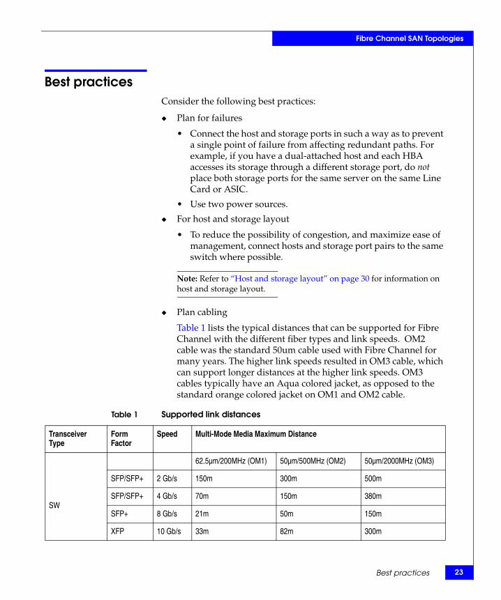
Table 1 lists the typical distances that can be supported for Fibre Channel with the different fiber types and link speeds. OM2 cable was the standard 50um cable used with Fibre Channel for many years. The higher link speeds resulted in OM3 cable, which can support longer distances at the higher link speeds. OM3 cables typically have an Aqua colored jacket, as opposed to the standard orange colored jacket on OM1 and OM2 cable.
Table 1 Supported link distances
Transceiver Type
Form Factor
Speed Multi-Mode Media Maximum Distance
SW
62.5µm/200MHz (OM1) 50µm/500MHz (OM2) 50µm/2000MHz (OM3)
SFP/SFP+ 2 Gb/s 150m 300m 500m
SFP/SFP+ 4 Gb/s 70m 150m 380m
SFP+ 8 Gb/s 21m 50m 150m
XFP 10 Gb/s 33m 82m 300m
Best practices 23
24
Fibre Channel SAN Topologies
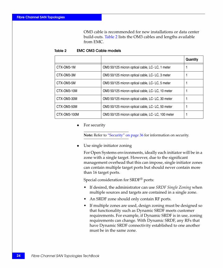
OM3 cable is recommended for new installations or data center build-outs. Table 2 lists the OM3 cables and lengths available from EMC.
◆ For security
Note: Refer to “Security” on page 36 for information on security.
◆ Use single initiator zoning
For Open Systems environments, ideally each initiator will be in a zone with a single target. However, due to the significant management overhead that this can impose, single initiator zones can contain multiple target ports but should never contain more than 16 target ports.
Special consideration for SRDF® ports:
• If desired, the administrator can use SRDF Single Zoning when multiple sources and targets are contained in a single zone.
• An SRDF zone should only contain RF ports.
• If multiple zones are used, design zoning must be designed so that functionality such as Dynamic SRDF meets customer requirements. For example, if Dynamic SRDF is in use, zoning requirements can change. With Dynamic SRDF, any RFs that have Dynamic SRDF connectivity established to one another must be in the same zone.
Table 2 EMC OM3 Cable models
Quantity
CTX-OM3-1M OM3 50/125 micron optical cable, LC- LC, 1 meter 1
CTX-OM3-3M OM3 50/125 micron optical cable, LC- LC, 3 meter 1
CTX-OM3-5M OM3 50/125 micron optical cable, LC- LC, 5 meter 1
CTX-OM3-10M OM3 50/125 micron optical cable, LC- LC, 10 meter 1
CTX-OM3-30M OM3 50/125 micron optical cable, LC- LC, 30 meter 1
CTX-OM3-50M OM3 50/125 micron optical cable, LC- LC, 50 meter 1
CTX-OM3-100M OM3 50/125 micron optical cable, LC- LC, 100 meter 1
Fibre Channel SAN Topologies TechBook
Fibre Channel SAN Topologies
• A maximum of 10 RFs per switch is recommended, for example when you have a two site configuration with four Symmetrix® DMX systems in each site. Each DMX contributes four SRDF ports. No single switch should have more than ten RFs connected to it. In this example, a minimum of two switches need to be deployed at each site. The main reason for restricting a switch to ten RFs is due to NameServer traffic. NameServer traffic is an important consideration and needs to be kept to a minimum to minimize link recovery times when RSCNs occur. By distributing across multiple switches, processing of NameServer traffic is also able to scale.
◆ Use dual management networks whenever two or more FC switches are being used
◆ Before building the SAN, gather the following customer-supplied information that will be needed during the implementation
• IP addresses, subnet mask, and gateway for each switch
• Information for each switch: – Switch names– Port names– Passwords – Number of HBAs and storage arrays to be connected to the
switchThese values are used in both manual and GUI-based setup methods.
◆ Use a port fencing policy
For more information on Port fencing, refer to “Port fencing” in the Networked Storage Concepts and Protocols TechBook, available through the E-Lab Interoperability Navigator, Topology Resource Center tab, at http://elabnavigator.EMC.com.
◆ Use the available performance monitoring tools
For more information on threshold alerts, refer to “Threshold alerts” in the Networked Storage Concepts and Protocols TechBook, available through the E-Lab Interoperability Navigator, Topology Resource Center tab, at http://elabnavigator.EMC.com.
Best practices 25
26
Fibre Channel SAN Topologies
◆ Use the latest supported firmware version and ensure that the same version of firmware is used throughout the fabric. In homogeneous switch vendor environments, all switch firmware versions inside each fabric should be equivalent, except during the firmware upgrade process.
Note: Refer to the EMC Support Matrix for the most up-to-date information.
◆ Periodically (or following any changes) back up switch configurations
◆ Utilize a syslog server
Note: It is also recommended to install an NTP client on the syslog server.
◆ Use persistent Domain IDs
◆ Estimate light budget
The following are switch-specific best practices.
Connectrix B
Firmware download
Preparing for a firmware download
Before executing a firmware download, performing the following tasks is recommended. This information will not only help validate that the firmware download did not disrupt the existing configuration, but also provide the support team with sufficient information in an unlikely event that something goes wrong after a firmware download.
1. Establish a Telnet session and log in to the Connectrix B switch.
2. It is advisable to have session logging enabled so that the output of your commands is saved to a file.
3. Enter the switchShow command to display switch information.
4. Enter the portCfgShow command to display current switch port settings.
5. Enter the nsShow command to display the total number of devices in the switch local Name Server database.
Fibre Channel SAN Topologies TechBook
Fibre Channel SAN Topologies
6. Enter the nsAllShow command to display the total number of devices in the switch global Name Server database.
7. Enter the fabricShow command to display the total number of domains in the fabric. If you are changing a dual domain Connectrix B director to a single domain Connectrix B director, this value will be one domain less after the operation.
8. Display the MIB configuration information using the snmpMibCabShow or agtCfgShow command.
9. Upload the switch configuration settings to an FTP server using the configUpload command.
10. Enter the supportShow and supportSave commands (these commands are version dependent) to provide baseline information for advanced support.
Note: If you are upgrading a Connectrix B director that is configured with two logical domains, perform these steps for both logical switches.
Before you enter the firmwareDownload command, read the release notes for the new firmware to find out if there are any firmware download issues.
After the firmwareDownload on a Connectrix B director switch, it is recommended you validate that the firmware versions have been synchronized on both CPs.
ZoningNote the following best practices:
◆ A zoneset can be managed and activated from any switch in the fabric, but it is recommended that it be managed from a single entry switch within a fabric to avoid any complications with multiple users accessing different switches in a fabric to make concurrent zone changes.
◆ The system administrators should coordinate zoning configuration activity to avoid running into a situation where two administrators are making changes simultaneously.
◆ To avoid any lengthy outages due to errors in Connectrix B SAN configurations it is recommended to backup the existing configuration before making any changes.
Best practices 27
28
Fibre Channel SAN Topologies
◆ In order to avoid the high risk involved in adding a new unauthorized switch to a Connectrix B fabric, it is advisable to limit the creation of switch-to-switch ports. This can be done by locking the already connected switch-to-switch ports in the SAN using the portCfgEport command. Such locking down of E_Ports is persistent across reboots. A portCfgEport <port number>,0 <disable> must be run on ports that are not connected to other switches in the fabric to block them from forming ISLs between switches.
ISL trunkingMore than a best practice, the administrator configuring a Connectrix B SAN must be aware that the frame-level trunking for Connectrix B switches requires all ports in a given ISL trunk to reside within an ASIC group on each end of the link.
◆ On 2 Gb/s switches, port groups are built on contiguous 4-port groups called quads. For example, on a Connectrix DS-8B2, there are two quads: ports 0-3 and ports 4-7.
◆ On 4 Gb/s switches like the Connectrix DS-4100B, trunking port groups are built on contiguous 8-port groups called octets. In this product, there are four octets: ports 0-7, 8-15, 16-23, and 24-31.
The administrator must use the ports within a group specified above to form an ISL trunk. It is also possible to configure multiple trunks within a port group.
Connectrix MDSThe following are requirements and guidelines for using IVR NAT:
IVR NAT port login (PLOGI) requests received from hosts are delayed for a few seconds to perform the rewrite on the FC ID address. If the host's PLOGI timeout value is set to a value less than five seconds, it may result in the PLOGI being unnecessarily aborted and the host being unable to access the target. EMC® recommends that you configure the host bus adapter for a timeout of at least ten seconds (most HBAs default to a value of 10 or 20 seconds).
Fibre Channel SAN Topologies TechBook
Fibre Channel SAN Topologies
Note: IVR NAT requires Cisco MDS SAN-OS Release 2.1(1a) or later on all switches in the fabric performing IVR. If you have isolated switches with an earlier release that are involved in IVR, you must remove any isolated fabrics from being monitored by Fabric Manager server and then re-open the fabric to use IVR NAT.
Connectrix M◆ When using Connectrix Manager, persist the fabric after setup is
complete.
◆ Where possible, configure the SAN to use Open Fabric Mode 1.0.
QLogic◆ A zoneset can be managed and activated from any switch in the
fabric, but it is recommended that it be managed from a single entry switch within a fabric.
◆ When configuring a switch using the Enterprise Fabric Suite, users are presented with several GUI wizard screens. The defaults are usually the switch best practice settings. User must verify the following default zoning-based settings:
• Autosave
– True: All zoneset merges from the fabric are automatically saved to NVRAM and maintained as a configured copy.
– False: A cached RAM copy of the merged database will be available for viewing and editing.
– Default setting: True.• DiscardInactive Zone
– True: If this parameter is set to True, all inactive zoning objects on a switch will be discarded. This may prevent the zone database from growing too large and consuming all the allowed space reserved on a switch for the zoning database. It may also prevent a switch from isolating unnecessarily.
– False: If this parameter is set to False, all inactive zoning objects will remain in the configured zoning information on a switch.
– Default setting: False.
Best practices 29
30
Fibre Channel SAN Topologies
• DefaultZone
– Allow: All devices connected to the switched fabric can see each other if they are not specified as part of a zone.
– Deny: Devices connected to the switch cannot see each other unless a zone is activated.
– Default setting: Allow for all edge switches.Deny for the SB9000.
◆ The system administrators should coordinate zoning configuration activity to avoid running into a situation where two administrators are making changes simultaneously.
◆ If using FCID or Domain port zone member types, EMC recommends that the Domain ID of each switch in the fabric be locked.
◆ When a new switch is installed in a fabric, EMC recommends not to have a configured zoning database or an Active zoneset. Run the reset zoning command to clear zone.
Host and storage layout
The correct way to attach hosts and storage to a SAN is completely dependent upon customer environments. Historically, the best practice placed hosts on edge switches and high-use storage ports on core switches. This was recommended because high-use storage ports are sometimes accessed by many different hosts on different parts of the fabric. If this is the case in your environment, this configuration would still be the best option. However, if you have high-use storage ports that are only accessed by a couple of hosts and it is possible to locate them all on the same switch, this is the preferred configuration instead of forcing the use of ISLs. ISLs are a valuable and limited resource and should be reserved for providing connectivity between ports that are unable to be placed on the same switch.
With this in mind, the following information provides helpful general guidelines:
◆ Whenever practical, locate HBAs and the storage ports they will access on the same switch. If it is not practical to do this, minimize the number of ISLs the host and storage need to traverse.
Fibre Channel SAN Topologies TechBook

Fibre Channel SAN Topologies
◆ Some of the switch class products being produced today only contain a single ASIC. If this is the case, then the positioning of the host and storage ports is strictly a matter of personal preference. However, if the switch being used contains multiple ASICs, try to connect host and storage pairs to the same ASIC. This prevents using the shared internal data transfer bus and reduces switch latency. In addition to performance concerns, consider fault tolerance as well. For example, if a host has two HBAs, each one accessing its own storage port, do not attach both HBAs, both storage ports, or all of the HBA and storage ports to the same ASIC.
Note: If you are unsure of the ASIC layout for the switch you are working with, refer to the EMC Connectrix SAN Products Data Reference Manual, available through the E-Lab Interoperability Navigator, Topology Resource Center tab, at http://elabnavigator.EMC.com.
◆ When working with hosts that have more than one connection to more than one storage port, always connect the HBAs and, if possible, the storage ports that it accesses to different FC switches. If a completely separate fabric is available, connect each HBA and storage port pair to different fabrics. Refer to the “Methodology 1: Balanced fabrics” located in the Networked Storage Concepts and Protocols TechBook, available through the E-Lab Interoperability Navigator, Topology Resource Center tab, at http://elabnavigator.EMC.com.
Best practices 31
32
Fibre Channel SAN Topologies
Switch and fabric managementThe following are management interfaces common to all platforms:
◆ CLI
The command line interface can be accessed through Telnet. On some platforms, it is also possible to access the CLI using a serial cable.
◆ SNMP
Simple Network Management Protocol is a TCP/IP protocol that generally uses the User Datagram Protocol (UDP) to exchange messages between a management device and a network management system.
Specific switch and fabric management information follows.
Connectrix B All switches in the EMC Connectrix B family can be managed by CLI, Web Tools, and Fabric Manager. EMC supports the use of EZSwitchSetup for the Connectrix DS-220B and the DS-4100B Fibre Channel switch products.
◆ Web Tools
Web Tools provides switch/fabric management through a web browser pointed to the IP address of the switch. Brocade uses a built-in web server for this function.
◆ Fabric Manager
Fabric Manager is a licensed management application used to manage a single switch or a large SAN in real-time.
◆ EZSwitchSetup
EZSwitchSetup is an easy-to-use web-based management application that allows you to assign the IP address, switch name, time, switch password, and zoning configuration.
EZSwitchSetup assists in the setup of a single switch SAN using either the Connectrix DS-4100B or the DS-220B. EZSwitchSetup uses the admin account as the default login.
Fibre Channel SAN Topologies TechBook
Fibre Channel SAN Topologies
EZSwitchSetup can assist with the following functions in a single switch SAN:
• Monitor the switch, including port and FRU status• Manage basic zoning• Perform basic switch configurations
EZSwitchSetup gives the SAN administrator the ability to choose from three different zoning options:
• Typical Zoning
By selecting the Typical Zoning option, user-selectable ports are zoned for storage devices, and the remaining are used for hosts. EZSwitchSetup automatically creates a zone with the storage ports and host ports using the port zoning method. No device WWN is needed for this setup, and the devices do not have to be connected. The GUI shows you where to hook both the host and storage devices when finished.
Select Typical Zoning if:
– You want to set up and manage a switch without knowing about domains.
– You do not know how zoning works.– You do not know where to connect devices.
• Custom Zoning
By selecting the Custom Zoning option, the user is given a matrix of all storage and host ports connected to the switch. This allows the user the option of customizing which hosts can access which storage by selecting the crossing point of each storage and host.
Select Custom Zoning if:
– You want to customized which initiators access which targets, but do not want to configure the zones yourself.
• Advanced Zoning
By selecting the Advanced Zoning option, the advanced zoning tool used in Web Tools is launched and you have the option of using mixed zoning (port and WWN) on the switch.
Select Advanced Zoning if:
– You are very familiar with zoning and zoning practices.
Switch and fabric management 33
34
Fibre Channel SAN Topologies
Connectrix MDS◆ Device Manager
◆ Fabric Manager
◆ Fabric Manager server
Connectrix M
◆ Connectrix Manager Basic
Connectrix Manager Basic software, formerly SANpilot, is a web-based management tool for small and medium businesses. It allows for management of fabrics with up to six switches. It is included at no extra cost on every Brocade M series Sphereon fabric switch.
◆ Connectrix Manager
Connectrix Manager is a stand-alone Java-based application that utilizes a client/server architecture to provide a management interface. The Connectrix Manager server is a headless application that runs on the service processor.
Note: The service processor provides a dial-home facility and data backup function.
The Connectrix Manager server also provides an interface for Connectrix Manager clients, an SNMP Agent, alerting using SNMP traps/email, and an ECCAPI to allow for management through EMC IonixTM ControlCenter®.
The Connectrix Manager client runs on both the Service Processor and on remote workstations, and it is the visible user interface to the server.
Fibre Channel SAN Topologies TechBook
Fibre Channel SAN Topologies
QLogicAt the time of this publication, the following applications can be used to manage a QLogic fabric:
◆ Enterprise Fabric Suite 2007
The Enterprise Fabric Suite 2007 is a combined application for management of multiple QLogic fabrics, for performance monitoring, fabric monitoring, and extended distance. The Enterprise Fabric Suite 2007 replaces the SANsurfer Switch Manager that QLogic supported before the 6.2.x firmware code.
◆ Quicktools
Quicktools is an embedded application for basic discovery, setup, configuration, and zoning management for a QLogic switch. It replaces the embedded SANsurfer Switch Manager that QLogic supported before the 6.2.x firmware code.
Switch and fabric management 35
36
Fibre Channel SAN Topologies
SecurityIt is important to secure your fabric. General security best practices for an FC SAN are as follows:
◆ Implement some form of zoning
◆ Change default password
◆ Disable unused or infrequently used Management Interfaces
◆ Use SSL or SSH if available
◆ Limit physical access to FC switches
Specific switch and fabric management information follows.
Connectrix BFabric Operating Software (FOS) versions 5.2.x and above now include an access control list (ACL) feature which gives the SAN administrator the ability to restrict both device and switch login throughout the fabric.
The following two ACL policies offer the base Fabric Operating System (FOS):
◆ Device Connection Control (DCC) policy
◆ Switch Connection Control (SCC) policy
FOS versions 5.2.x and above introduced Role Based Access Control (RBAC).
Also introduced in FOS versions 5.2.x and above was the concept of Admin Domains (AD).
To maintain a secure network, you should avoid using Telnet (you can use secTelnet if you are using Fabric OS v2.6 or later, or v3.1 or later), or any other unprotected application when you are working on the switch. For example, if you use Telnet to connect to a machine, and then start an SSH or secure Telnet session from that machine to the switch, the communication to the switch is in clear text and therefore not secure.
The FTP protocol is also not secure. When you use FTP to copy files to or from the switch, the contents are in clear text. This includes the remote FTP server login and password. This limitation affects the
Fibre Channel SAN Topologies TechBook
Fibre Channel SAN Topologies
following commands: saveCore, configUpload, configDownload, and firmwareDownload.
Connectrix MDS
The MDS supports SSH and SFTP protocols.
Connectrix M
After the environment has been configured and all hosts see the appropriate volumes, configure the following security features.
◆ For homogeneous Brocade M series fabrics:
• If Enterprise Fabric mode is available, enable it.
• If Enterprise Fabric mode is not available, enable:
– Fabric Binding– Switch Binding– Port Binding
◆ For heterogeneous fabrics containing Brocade M series switches:
• Enable Switch Binding and Port Binding.
QLogicAfter building the QLogic fabric, it is important to secure the fabric.
◆ QLogic switches offer a mix of fabric security protection features which include user security, connection security, and device security.
◆ The data path for switch management communication is encrypted using secure shell (SSH) for the CLI and Secure Sockets Layer (SSL) for Enterprise Fabric Suite 2007 and Quicktools.
◆ Users can set up device connection security to control what devices have access to the switch. ISL and port authentication is achieved using Fibre Channel Security Protocol (FC-SP) and DH-CHAP. Additional device authentication is performed using FC-GS-4 Ct.
◆ The Port Binding security feature was introduced in the latest firmware v6.2.1 supported at the time of this publication. As a part of the QLogic security feature, Port Binding enables the
Security 37
38
Fibre Channel SAN Topologies
specification of WWNs that are allowed to connect to a switch port. Up to 32 WWNs may be specified. Port Binding is available through the CLI set config security port command.
For more information on these security features, refer to the Building Secure SANs TechBook, available through the E-Lab Interoperability Navigator, Topology Resource Center tab, at http://elabnavigator.EMC.com.
The SANbox 5602 Switch Management User’s Guide, Managing Fabrics is available at http://www.qlogic.com discusses how to enable security features using switch management interfaces.
Fibre Channel SAN Topologies TechBook
2Invisible Body Tag
This chapter provides the following information on simple Fibre Channel SAN topologies.
◆ Single switch fabrics .......................................................................... 40◆ Two switch fabrics.............................................................................. 69◆ Blade switch with direct attached storage.................................... 120
Simple Fibre ChannelSAN Topologies
Simple Fibre Channel SAN Topologies 39
40
Simple Fibre Channel SAN Topologies
Single switch fabricsThis section provides examples of single switch fabrics.
Overview of fabric design considerations
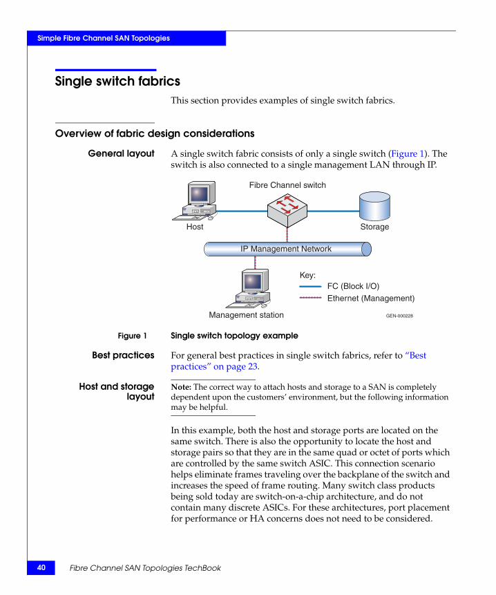
General layout A single switch fabric consists of only a single switch (Figure 1). The switch is also connected to a single management LAN through IP.
Figure 1 Single switch topology example
Best practices For general best practices in single switch fabrics, refer to “Best practices” on page 23.
Host and storagelayout
Note: The correct way to attach hosts and storage to a SAN is completely dependent upon the customers’ environment, but the following information may be helpful.
In this example, both the host and storage ports are located on the same switch. There is also the opportunity to locate the host and storage pairs so that they are in the same quad or octet of ports which are controlled by the same switch ASIC. This connection scenario helps eliminate frames traveling over the backplane of the switch and increases the speed of frame routing. Many switch class products being sold today are switch-on-a-chip architecture, and do not contain many discrete ASICs. For these architectures, port placement for performance or HA concerns does not need to be considered.
GEN-000228
IP Management Network
Fibre Channel switch
Storage
Management station
Host
Key:FC (Block I/O)
Ethernet (Management)
Fibre Channel SAN Topologies TechBook
Simple Fibre Channel SAN Topologies
For general information on host and storage layout in single switch fabrics, refer to “Host and storage layout” on page 30.
Switch and fabricmanagement
All switch and fabric management tools can be used to configure this environment. For general information on switch and fabric management, refer to “Switch and fabric management” on page 32.
Security Even when dealing with single switch fabrics, it is important to think about security. Typically, in a single switch fabric, if physical access to the switch can be controlled, default passwords are changed, and unused interfaces are disabled, zoning will be enough to secure the fabric. It is also recommended to implement some form of Port Binding. This can be as simple as enabling Port Binding if the feature exists, or as complicated as disabling all unused ports and hard-setting port type to F_Port.
For more information on security, refer to “Security” on page 36.
Connectrix B example
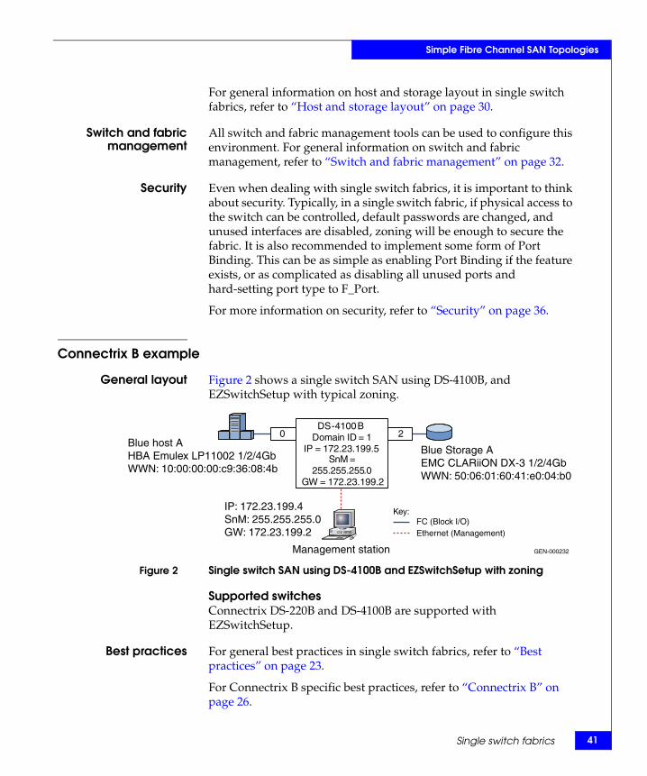
General layout Figure 2 shows a single switch SAN using DS-4100B, and EZSwitchSetup with typical zoning.
Figure 2 Single switch SAN using DS-4100B and EZSwitchSetup with zoning
Supported switchesConnectrix DS-220B and DS-4100B are supported with EZSwitchSetup.
Best practices For general best practices in single switch fabrics, refer to “Best practices” on page 23.
For Connectrix B specific best practices, refer to “Connectrix B” on page 26.
GEN-000232
Key:
Management station
20
FC (Block I/O)Ethernet (Management)
DS-4100BDomain ID = 1
IP = 172.23.199.5SnM =
255.255.255.0GW = 172.23.199.2
P
Blue host AHBA Emulex LP11002 1/2/4GbWWN: 10:00:00:00:c9:36:08:4b
Blue Storage AEMC CLARiiON DX-3 1/2/4GbWWN: 50:06:01:60:41:e0:04:b0
IP: 172.23.199.4SnM: 255.255.255.0GW: 172.23.199.2
Single switch fabrics 41
42
Simple Fibre Channel SAN Topologies
Host and storagelayout
When using Typical Zoning in EZSwitchSetup, the GUI guides the SAN administrator on recommended placement of both host and storage.
In a single switch SAN design, both hosts and storage can be placed anywhere on the switch. Connectrix B switches group ASIC-controlled port groups, either by quad or octet. In some circumstances, you should connect both host and storage to these groups which eliminates frames from traveling through the backplane of the switch to reach their destination.
For general information on host and storage layout in single switch fabrics, refer to “Host and storage layout” on page 30.
Switch and fabricmanagement
For this case study, the EZSwitchSetup tool is used to setup a Connectrix DS-4100B switch with one host and one storage array. EZSwitchSetup offers three zoning options. The Typical Zoning option is used in this case study. For more information on EZSwitchSetup, refer to “EZSwitchSetup” on page 32.
For general information on host and storage layout in single switch fabrics, refer to “Switch and fabric management” on page 32.
Security For general information on security in single switch fabrics, refer to “Security” on page 36.
Setting up thistopology
Assumptions specific to this case study:
◆ The switch is not powered on.
◆ Network drop, IP addresses, subnet mask, and gateway are provided by the customer.
◆ License keys have been obtained.
• Go to the URL listed on the transaction code certificate that shipped with the product to get the license key.
◆ The customer has provided a server or laptop with CD drive, serial DB-9 connector, and a NIC card to be used to configure the switch.
◆ Configuration will be done using the EZSwitchsetup CD.
Configure a single switch SAN
To configure a single switch SAN, follow these steps:
Note: Host and storage ports do not have to be connected until Step 8.
Fibre Channel SAN Topologies TechBook
Simple Fibre Channel SAN Topologies
1. Power-on the switch.
2. Connect to the switch management port using RS-232 serial cable. Set the workstation serial port to use 9600 baud rate, 8 databits, no parity, 1 stop bit, and no flow control.
3. Connect RJ-45 network cable from the workstation to the network management port of switch.
4. Launch the EZSwitchSetup CD.
5. Issue the switch IP address (172.23.199.5), subnet mask (255.255.255.0), and default gateway (172.23.199.2), and then click Next.
6. Supply a password for the Admin account, issue a switch name, change the date, and then click Next.
7. Select Typical Zoning, on the Select Zoning screen, and then click Next.
8. Select the ports as host or storage on the Configure Typical Zoning screen, and then click Next. Each time you click, you toggle the port between a desired host port, designated by the color blue, the letter H, and a desired storage port, designated by the color green, and the letter S.
9. Connect host and storage using the Configure Typical Zoning GUI as a guide.
10. Use the pull-down menu selections on the Specify Devices screen to select the number of HBA connections and the number of storage connections planned for the switch, and then click Next.
11. The Connect Devices screen provides a graphical view of recommended connections for both host and storage on the switch. Connection status is represented by colored lines.
• A green line indicates a good connection• A red line indicates an invalid connection• A blue dashed line indicates a missing connection
Click Next.
12. The Finish screen supplies a summary of the switch configuration and allows you to print the configuration if needed. Click Finish.
Single switch fabrics 43
44
Simple Fibre Channel SAN Topologies
13. Validate zoning configuration by ensuring that each HBA has access to the storage device(s).
Each HBA should see every storage device when using Typical Zoning.
The Validate link in the task panel of the Switch Manager page checks for devices that are not zoned properly, allows you to delete the devices from the zoning database, and displays a matrix of which HBA can see which storage device.
Connectrix MDS example
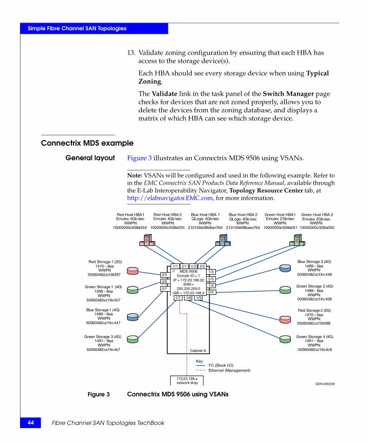
General layout Figure 3 illustrates an Connectrix MDS 9506 using VSANs.
Note: VSANs will be configured and used in the following example. Refer to in the EMC Connectrix SAN Products Data Reference Manual, available through the E-Lab Interoperability Navigator, Topology Resource Center tab, at http://elabnavigator.EMC.com, for more information.
Figure 3 Connectrix MDS 9506 using VSANs
GEN-000239
Key:
1/5
172.23.199.x network drop
Cabinet A
Red Host HBA 1 Emulex 4 Gb / sec
WWPN 10000000 c 938 e 554
Red Host HBA 2 Emulex 4 Gb / sec
WWPN 10000000 c 938 e 555
Green Host HBA 1 Emulex 2 Gb / sec
WWPN 10000000 c 939 a 051
Green Host HBA 2 Emulex 2 Gb / sec
WWPN 10000000 c 939 a 052
Blue Host HBA 1QLogic 4 Gb / sec
WWPN 210100 e 08 b 8 ac 76 d
Blue Host HBA 2 QLogic 4 Gb / sec
WWPN 210100 e 08 baac 76 d
Red Storage 2 (2G)1470 – 9aa
WWPN50060482cc19bf88
Red Storage 1 (2G)1470 – 8 aa
WWPN 50060482 cc 19 bf 87
Green Storage 1 (4G)1488 – 8 aa
WWPN 50060482 cc 19 c 407
Green Storage 2 (4G)1488 – 9aa
WWPN50060482cc19c408
Blue Storage 1 ( 4 G ) 1489 – 8 aa
WWPN 50060482 cc 19 c 447
Blue Storage 2 (4G)1489 – 9aa
WWPN50060482cc19c448
Green Storage 3 ( 4 G ) 1491 – 8 aa
WWPN 50060482 cc 19 c 4 c 7
Green Storage 4 (4G)1491 – 9aa
WWPN50060482cc19c4c8
2/11/11/3
1/2 2/2
1/7 1/6
1/4
2/3
2/4
2/5
2/6
2/7
FC (Block I/O)Ethernet (Management)
MDS 9506Domain ID = 1
IP = 172 . 23 . 199 . 22 SnM =
255 . 255 . 255 . 0 GW = 172 . 23 . 199 . 2
P
Fibre Channel SAN Topologies TechBook
Simple Fibre Channel SAN Topologies
Best practices For general information on best practices in single switch fabrics, refer to “Best practices” on page 40. Specific information for this example follows.
Port fencing is on by default.
Host and storagelayout
For general information on host and storage layout in single switch fabrics, refer to “Host and storage layout” on page 40. Specific information for this example follows.
There are no host or storage restrictions for Line Rate Mode cards. Oversubscribed cards should be used for hosts only.
Switch and fabricmanagement
For general information on switch and fabric management in single switch fabrics, refer to “Switch and fabric management” on page 41. Specific information for this example follows.
Cisco Fabric Manager can be used for this example.
Security For general information on security in single switch fabrics, refer to “Security” on page 41. Specific information for this example follows.
Port Binding can be used for security.
Setting up thistopology
Assumptions specific to this case study:
◆ The switches are installed in an EMC-supplied cabinet.
• For installation instructions, see Connectrix EC-1500 Cabinet Installation and Setup Manual, which can be accessed from Powerlink.
◆ The proper power receptacles have been provided by the customer.
• For switch power requirements, refer to the EMC Connectrix SAN Products Data Reference Manual, available through the E-Lab Interoperability Navigator, Topology Resource Center tab, at http://elabnavigator.EMC.com.
• For Cabinet power requirements, refer to Connectrix EC-1500 Cabinet Installation and Setup Manual, which can be accessed from Powerlink.
◆ The switches have not been connected to the power source and are not powered on.
◆ Network drops, IP addresses, subnet mask, and gateway have been provided by the customer.
Single switch fabrics 45
46
Simple Fibre Channel SAN Topologies
• For switch or cabinet network requirements, refer to the EMC Connectrix SAN Products Data Reference Manual, available through the E-Lab Interoperability Navigator, Topology Resource Center tab, at http://elabnavigator.EMC.com.
Note: Connectrix MDS switches can be placed on either a public or private network. There are advantages to both configurations. For more information, refer to "Public versus private" in the Networked Storage Concepts and Protocols TechBook, available through the E-Lab Interoperability Navigator, Topology Resource Center tab, at http://elabnavigator.EMC.com.
In this example it is assumed that the customer has provided one Ethernet cable and an IP of 172.23.199.22.
◆ The proper number of line cards have been installed in each chassis. In this case, two line cards in each chassis are required and installed in slots 1 and 2.
• For help in determining how many ports are required, see "Determining customer requirements" in the Networked Storage Concepts and Protocols TechBook, available through the E-Lab Interoperability Navigator, Topology Resource Center tab, at http://elabnavigator.EMC.com.
◆ License keys have been obtained.
• Go to the URL listed on the transaction code certificate that shipped with the product to get the license key.
◆ A laptop, supplied by the installer, will be used to configure the IP addresses of the switches, and this laptop has a serial DB-9 connector.
◆ The customer has provided a temporary password that will be used as the default password when configuring the IP address.
◆ Fabric Manager will be used for VSAN setup.
Configure the IP address
To configure the IP address:
1. Power up the cabinet by connecting power cords to the power receptacles provided by the customer.
2. Select one of the switches to configure and set the IP to 172.23.199.22.
3. Supply a network connection to the appropriate subnet.
Fibre Channel SAN Topologies TechBook
Simple Fibre Channel SAN Topologies
4. Connect to the serial port of the switch, using an RS232 serial cable, with a baud rate of 9600, 8 data bits, no parity, 1 stop bit and no flow control.
The login prompt appears.
5. Log in the first time with a username of admin and a password of admin.
You are prompted to supply a new strong password for CLI user admin.
6. For this example, select no when asked if you want to run setup.
Note: This example starts with the switch that has a Domain ID of 1 and an IP address of 172.23.199.22.
7. Repeat the above steps for each switch, supplying the appropriate IP.
CLI commands to configure the IP and gateway
◆ Switch# config terminal
Enter configuration commands, one per line.
Switch(config)# interface mgmt 0Switch(config-if)# IP address 172.23.199.22 255.255.255.0
End with CNTL/Z.
◆ Switch# config terminal
Enter configuration commands, one per line.
Switch(config)# ip default-gateway 172.23.199.2
End with CNTL/Z.
To authorize access on a switch for Device and Fabric Manager, run this command on every switch while supplying a username (nnn) and password (ppp):
◆ Switch#conf t
Switch(config)# snmp-server user nnn network-admin auth md5 pppSwitch(config)#endSwitch# copy running-config startup-configSwitch# exit
Single switch fabrics 47
48
Simple Fibre Channel SAN Topologies
Install Fabric Manager and Device Manager
To install Fabric Manager and Device Manager:
1. Open your web browser.
2. Enter the IP address of the switch into the address bar.
3. Follow the prompts and accept all defaults to install both Fabric Manager and Device Manager.
Fabric Manager and Device Manager can be started using the configured SNMP server username and password in “CLI commands to configure the IP and gateway” on page 47.
Configure a VSANTo configure a VSAN:
1. Open the Device Manager for the switch with an IP address of 172.23.199.22.
2. Open the VSAN dialog box by selecting VSAN.
3. Click Create.
4. Enter the value of 100 into the VSAN ID field.
5. Set the VSAN Name to be “Red_VSAN_100”.
6. Use the default interop mode.
7. Click Create.
Configure the other VSANs in this physical switchTo configure the other VSANs, complete the following steps:
1. Repeat Step 2 through Step 7, above, for VSAN 200 and 300 noting that:
• For Virtual switch 200, use a VSAN name of “Green_VSAN_200”.
• For Virtual switch 300, use a VSAN name of “Blue_VSAN_300”.
Fibre Channel SAN Topologies TechBook
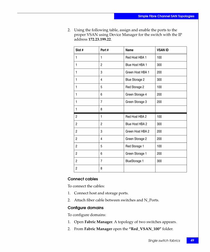
Simple Fibre Channel SAN Topologies
2. Using the following table, assign and enable the ports to the proper VSAN using Device Manager for the switch with the IP address 172.23.199.22.
Connect cables
To connect the cables:
1. Connect host and storage ports.
2. Attach fiber cable between switches and N_Ports.
Configure domains
To configure domains:
1. Open Fabric Manager. A topology of two switches appears.
2. From Fabric Manager open the “Red_VSAN_100” folder.
Slot # Port # Name VSAN ID
1 1 Red Host HBA 1 100
1 2 Blue Host HBA 1 300
1 3 Green Host HBA 1 200
1 4 Blue Storage 2 300
1 5 Red Storage 2 100
1 6 Green Storage 4 200
1 7 Green Storage 3 200
1 8
2 1 Red Host HBA 2 100
2 2 Blue Host HBA 2 300
2 3 Green Host HBA 2 200
2 4 Green Storage 2 200
2 5 Red Storage 1 100
2 6 Green Storage 1 200
2 7 BlueStorage 1 300
2 8
Single switch fabrics 49
50
Simple Fibre Channel SAN Topologies
3. Select Domain Manager.
4. Select the Configuration menu.
5. Set a Domain ID, 1 for switch 172.23.199.22 and 2 for 172.23.200.22.
6. To set a principal switch, set the priority to 1 in the domain menu.
7. Repeat Step 2 through Step 6 for “Green_VSAN_200” and “Blue_VSAN_300”.
Zone hosts and storage
To zone hosts and storage:
1. From Fabric Manager, select “Red_VSAN_100”.
2. Select Edit Full Zone Database.
3. Create a zone by selecting the Zone menu and clicking the Add button.
4. Provide a descriptive name for the zone. This example zones “Red host HBA 1” and “Red Storage 1”, so “RedHBA1_1470_8aa” will be used. Click OK.
5. Locate, then click, “Red Host HBA 1” (WWPN 10000000c938e554) in the Potential zone members list.
6. Click the right-pointing arrow on the divider between the Potential members list and the zones list to add the HBA to the zone. Select Add to zone or alias.
7. Locate, then click, “Red Storage 1” (WWPN 50060482cc19bf87) in the Potential zone members list.
8. Click the right-pointing arrow on the divider between the Potential members list and the zones list to add the Storage port to the zone.
9. Repeat Step 2 through Step 8 for all host and storage pairs in the environment.
10. Create a zone set by selecting the Zonesets menu, and then click the Add button.
11. Provide a descriptive name for the zone set. This example uses the name “RED Fabric 1”.
Add only those zones that are necessary on Red_Fabric_1. In this case, the two red zones listed below, "RedHBA1_1470_8aa" and
Fibre Channel SAN Topologies TechBook
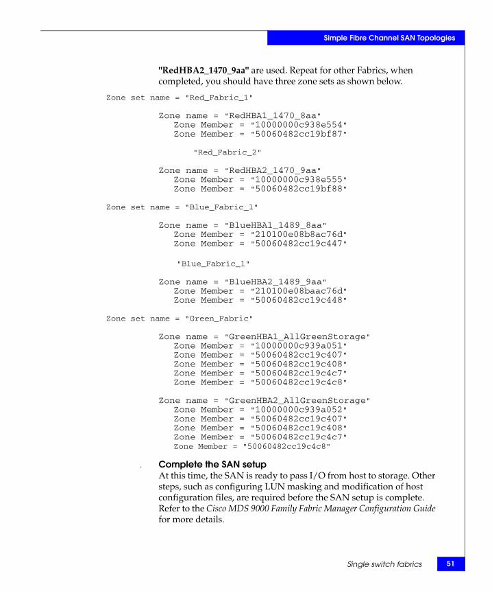
Simple Fibre Channel SAN Topologies
"RedHBA2_1470_9aa" are used. Repeat for other Fabrics, when completed, you should have three zone sets as shown below.
Zone set name = "Red_Fabric_1"
Zone name = "RedHBA1_1470_8aa"Zone Member = "10000000c938e554"Zone Member = "50060482cc19bf87"
"Red_Fabric_2"
Zone name = "RedHBA2_1470_9aa"Zone Member = "10000000c938e555"Zone Member = "50060482cc19bf88"
Zone set name = "Blue_Fabric_1"
Zone name = "BlueHBA1_1489_8aa"Zone Member = "210100e08b8ac76d"Zone Member = "50060482cc19c447"
"Blue_Fabric_1"
Zone name = "BlueHBA2_1489_9aa"Zone Member = "210100e08baac76d"Zone Member = "50060482cc19c448"
Zone set name = "Green_Fabric"
Zone name = "GreenHBA1_AllGreenStorage"Zone Member = "10000000c939a051"Zone Member = "50060482cc19c407"Zone Member = "50060482cc19c408"Zone Member = "50060482cc19c4c7"Zone Member = "50060482cc19c4c8"
Zone name = "GreenHBA2_AllGreenStorage"Zone Member = "10000000c939a052"Zone Member = "50060482cc19c407"Zone Member = "50060482cc19c408"Zone Member = "50060482cc19c4c7"Zone Member = "50060482cc19c4c8"
. Complete the SAN setupAt this time, the SAN is ready to pass I/O from host to storage. Other steps, such as configuring LUN masking and modification of host configuration files, are required before the SAN setup is complete. Refer to the Cisco MDS 9000 Family Fabric Manager Configuration Guide for more details.
Single switch fabrics 51
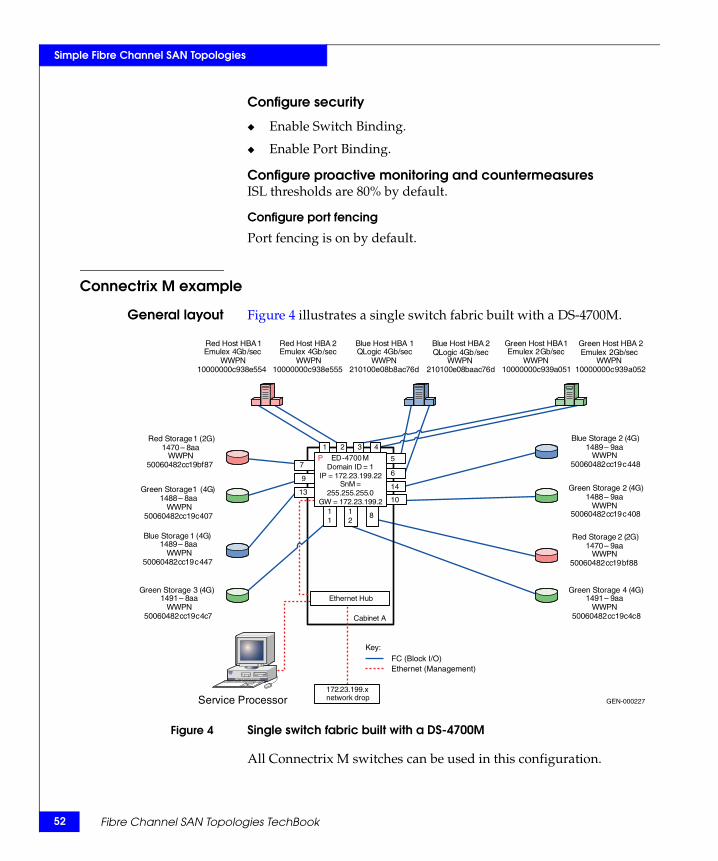
52
Simple Fibre Channel SAN Topologies
Configure security
◆ Enable Switch Binding.
◆ Enable Port Binding.
Configure proactive monitoring and countermeasuresISL thresholds are 80% by default.
Configure port fencing
Port fencing is on by default.
Connectrix M example
General layout Figure 4 illustrates a single switch fabric built with a DS-4700M.
Figure 4 Single switch fabric built with a DS-4700M
All Connectrix M switches can be used in this configuration.
GEN-000227
Key:
172 . 23 . 199 . x network drop
Cabinet A
Service Processor
Ethernet Hub
Red Host HBA 1 Emulex 4 Gb / sec
WWPN 10000000 c 938 e 554
Red Host HBA 2 Emulex 4 Gb / sec
WWPN 10000000 c 938 e 555
Green Host HBA 1 Emulex 2 Gb / sec
WWPN 10000000 c 939 a 051
Green Host HBA 2 Emulex 2 Gb / sec
WWPN 10000000 c 939 a 052
Blue Host HBA 1QLogic 4 Gb / sec
WWPN 210100 e 08 b 8 ac 76 d
Blue Host HBA 2 QLogic 4 Gb / sec
WWPN 210100 e 08 baac 76 d
Red Storage 2 (2G)1470 – 9aa
WWPN50060482cc19bf88
Red Storage 1 (2G)1470 – 8 aa
WWPN 50060482 cc 19 bf 87
Green Storage 1 ( 4 G ) 1488 – 8 aa
WWPN 50060482 cc 19 c 407
Green Storage 2 (4G)1488 – 9aa
WWPN50060482cc19c408
Blue Storage 1 ( 4 G ) 1489 – 8 aa
WWPN 50060482 cc 19 c 447
Blue Storage 2 (4G)1489 – 9aa
WWPN50060482cc19c448
Green Storage 3 ( 4 G ) 1491 – 8 aa
WWPN 50060482 cc 19 c 4 c 7
Green Storage 4 (4G)1491 – 9aa
WWPN50060482cc19c4c8
1 2
5
6
43
11
12
8
14
10
7
9
13
FC (Block I/O) Ethernet (Management)
ED-4700MDomain ID = 1
IP = 172 . 23 . 199 . 22 SnM =
255 . 255 . 255 . 0 GW = 172 . 23 . 199 . 2
P
Fibre Channel SAN Topologies TechBook
Simple Fibre Channel SAN Topologies
Best practices ◆ Configure threshold alerts:
Even though this is a single switch fabric and ISLs are not used, some benefits can still be realized from configuring threshold alerts, especially in configurations with large fan in and fan out ratios.
◆ Enable a fencing policy:
In this example, a fencing policy is enabled to help protect the switch from any misbehaving N_Ports. This is usually more of a concern on large port count switches where many misbehaving N_Ports can create an issue by tying up the switch processor with needless login requests. Even though this problem occurs in single switch fabrics, so we still recommend it as a best practice.
For general information on best practices in single switch fabrics, refer to “Best practices” on page 40.
Host and storagelayout
In this case study, a DS-4700M is utilized. Since the DS-4700M is a switch-on-a-chip type of architecture, the host and storage ports can be placed anywhere. No special considerations need to be made in regards to port placement for performance or HA related issues.
For general information on host and storage layout in single switch fabrics, refer to “Host and storage layout” on page 40.
Switch and fabricmanagement
Any management interface could be utilized to set up this environment, but in this case study Connectrix Manager Basic is used.
For general information on switch and fabric management in single switch fabrics, refer to “Switch and fabric management” on page 41.
Security In this example, unused interfaces are disabled and Web SSL, Fabric Binding, Switch Binding, and Port Binding are configured. See “Configure security” on page 59.
For general information on security in single switch fabrics, refer to “Security” on page 41. For more information on security, refer to in the Building Secure SANs TechBook, available through the E-Lab Interoperability Navigator, Topology Resource Center tab, at http://elabnavigator.EMC.com.
Setting up thistopology
Assumptions specific to this case study:
◆ The switch is installed in a customer-supplied cabinet.
◆ The customer has provided the proper power receptacles.
Single switch fabrics 53
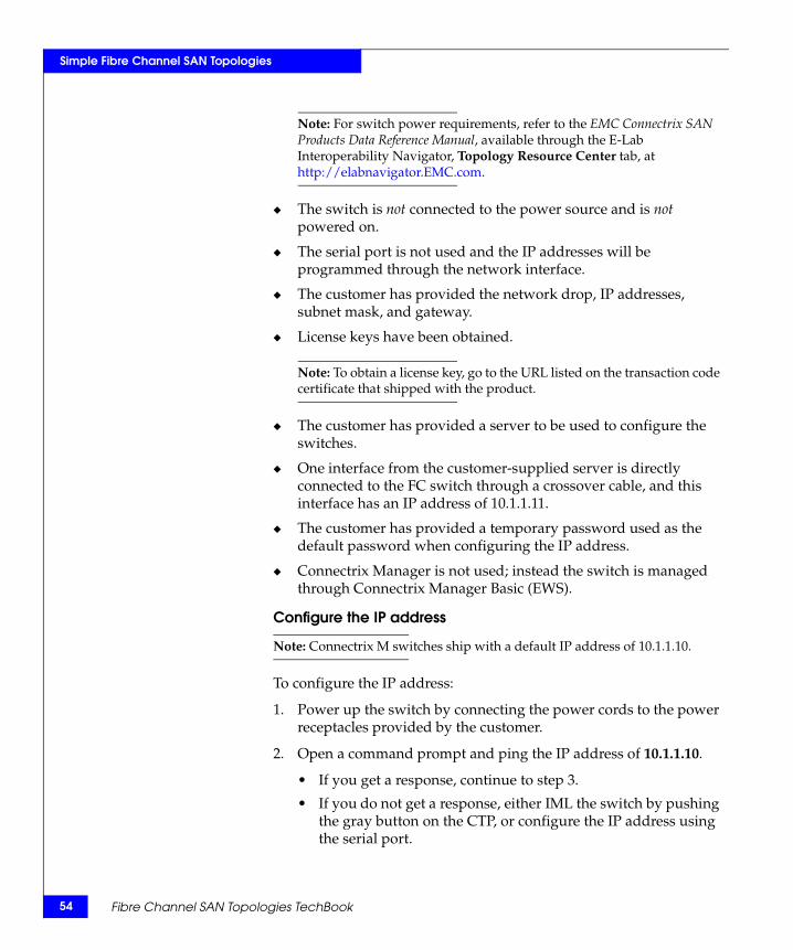
54
Simple Fibre Channel SAN Topologies
Note: For switch power requirements, refer to the EMC Connectrix SAN Products Data Reference Manual, available through the E-Lab Interoperability Navigator, Topology Resource Center tab, at http://elabnavigator.EMC.com.
◆ The switch is not connected to the power source and is not powered on.
◆ The serial port is not used and the IP addresses will be programmed through the network interface.
◆ The customer has provided the network drop, IP addresses, subnet mask, and gateway.
◆ License keys have been obtained.
Note: To obtain a license key, go to the URL listed on the transaction code certificate that shipped with the product.
◆ The customer has provided a server to be used to configure the switches.
◆ One interface from the customer-supplied server is directly connected to the FC switch through a crossover cable, and this interface has an IP address of 10.1.1.11.
◆ The customer has provided a temporary password used as the default password when configuring the IP address.
◆ Connectrix Manager is not used; instead the switch is managed through Connectrix Manager Basic (EWS).
Configure the IP address
Note: Connectrix M switches ship with a default IP address of 10.1.1.10.
To configure the IP address:
1. Power up the switch by connecting the power cords to the power receptacles provided by the customer.
2. Open a command prompt and ping the IP address of 10.1.1.10.
• If you get a response, continue to step 3.
• If you do not get a response, either IML the switch by pushing the gray button on the CTP, or configure the IP address using the serial port.
Fibre Channel SAN Topologies TechBook
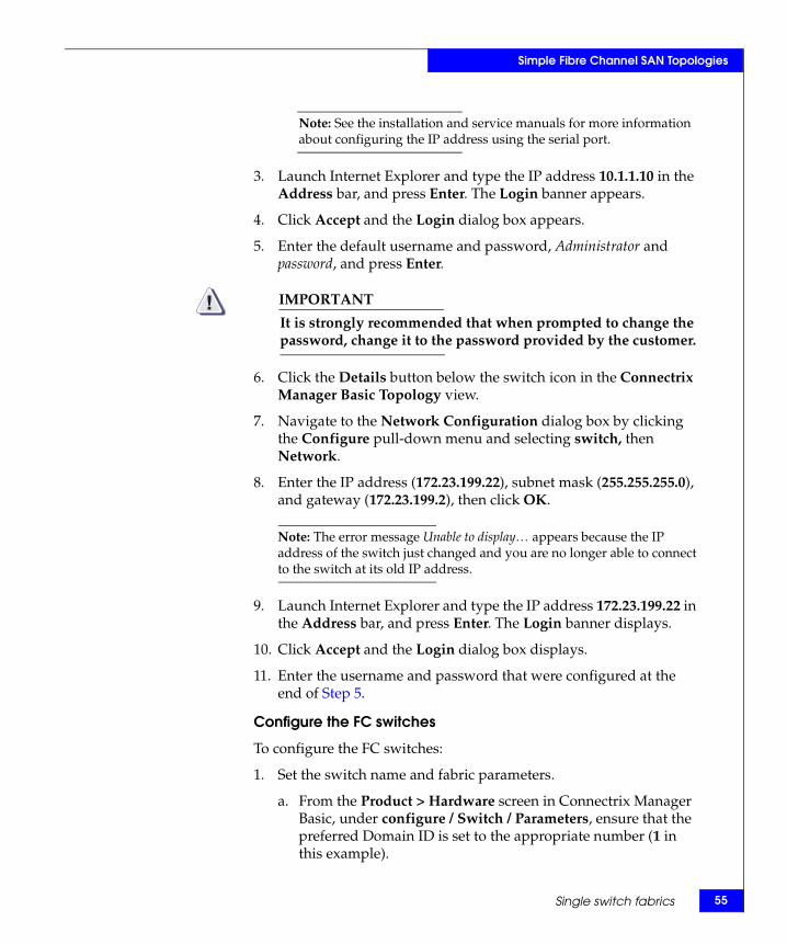
Simple Fibre Channel SAN Topologies
Note: See the installation and service manuals for more information about configuring the IP address using the serial port.
3. Launch Internet Explorer and type the IP address 10.1.1.10 in the Address bar, and press Enter. The Login banner appears.
4. Click Accept and the Login dialog box appears.
5. Enter the default username and password, Administrator and password, and press Enter.
IMPORTANT!It is strongly recommended that when prompted to change the password, change it to the password provided by the customer.
6. Click the Details button below the switch icon in the Connectrix Manager Basic Topology view.
7. Navigate to the Network Configuration dialog box by clicking the Configure pull-down menu and selecting switch, then Network.
8. Enter the IP address (172.23.199.22), subnet mask (255.255.255.0), and gateway (172.23.199.2), then click OK.
Note: The error message Unable to display… appears because the IP address of the switch just changed and you are no longer able to connect to the switch at its old IP address.
9. Launch Internet Explorer and type the IP address 172.23.199.22 in the Address bar, and press Enter. The Login banner displays.
10. Click Accept and the Login dialog box displays.
11. Enter the username and password that were configured at the end of Step 5.
Configure the FC switches
To configure the FC switches:
1. Set the switch name and fabric parameters.
a. From the Product > Hardware screen in Connectrix Manager Basic, under configure / Switch / Parameters, ensure that the preferred Domain ID is set to the appropriate number (1 in this example).
Single switch fabrics 55
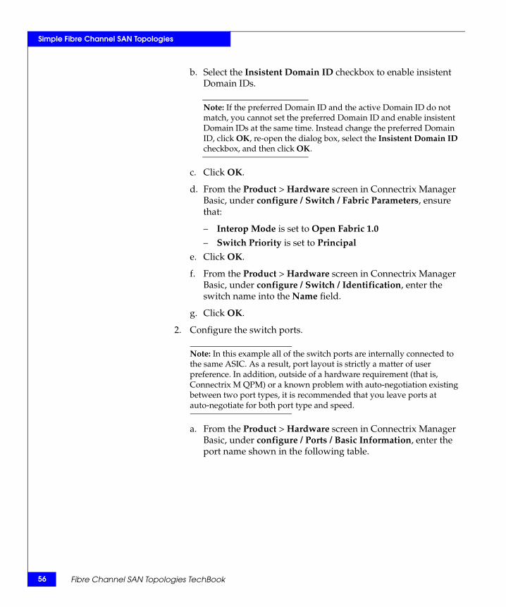
56
Simple Fibre Channel SAN Topologies
b. Select the Insistent Domain ID checkbox to enable insistent Domain IDs.
Note: If the preferred Domain ID and the active Domain ID do not match, you cannot set the preferred Domain ID and enable insistent Domain IDs at the same time. Instead change the preferred Domain ID, click OK, re-open the dialog box, select the Insistent Domain ID checkbox, and then click OK.
c. Click OK.
d. From the Product > Hardware screen in Connectrix Manager Basic, under configure / Switch / Fabric Parameters, ensure that:
– Interop Mode is set to Open Fabric 1.0
– Switch Priority is set to Principal
e. Click OK.
f. From the Product > Hardware screen in Connectrix Manager Basic, under configure / Switch / Identification, enter the switch name into the Name field.
g. Click OK.
2. Configure the switch ports.
Note: In this example all of the switch ports are internally connected to the same ASIC. As a result, port layout is strictly a matter of user preference. In addition, outside of a hardware requirement (that is, Connectrix M QPM) or a known problem with auto-negotiation existing between two port types, it is recommended that you leave ports at auto-negotiate for both port type and speed.
a. From the Product > Hardware screen in Connectrix Manager Basic, under configure / Ports / Basic Information, enter the port name shown in the following table.
Fibre Channel SAN Topologies TechBook
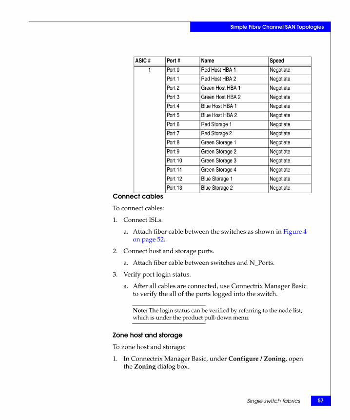
Simple Fibre Channel SAN Topologies
Connect cables
To connect cables:
1. Connect ISLs.
a. Attach fiber cable between the switches as shown in Figure 4 on page 52.
2. Connect host and storage ports.
a. Attach fiber cable between switches and N_Ports.
3. Verify port login status.
a. After all cables are connected, use Connectrix Manager Basic to verify the all of the ports logged into the switch.
Note: The login status can be verified by referring to the node list, which is under the product pull-down menu.
Zone host and storage
To zone host and storage:
1. In Connectrix Manager Basic, under Configure / Zoning, open the Zoning dialog box.
ASIC # Port # Name Speed
1 Port 0 Red Host HBA 1 Negotiate
Port 1 Red Host HBA 2 Negotiate
Port 2 Green Host HBA 1 Negotiate
Port 3 Green Host HBA 2 Negotiate
Port 4 Blue Host HBA 1 Negotiate
Port 5 Blue Host HBA 2 Negotiate
Port 6 Red Storage 1 Negotiate
Port 7 Red Storage 2 Negotiate
Port 8 Green Storage 1 Negotiate
Port 9 Green Storage 2 Negotiate
Port 10 Green Storage 3 Negotiate
Port 11 Green Storage 4 Negotiate
Port 12 Blue Storage 1 Negotiate
Port 13 Blue Storage 2 Negotiate
Single switch fabrics 57
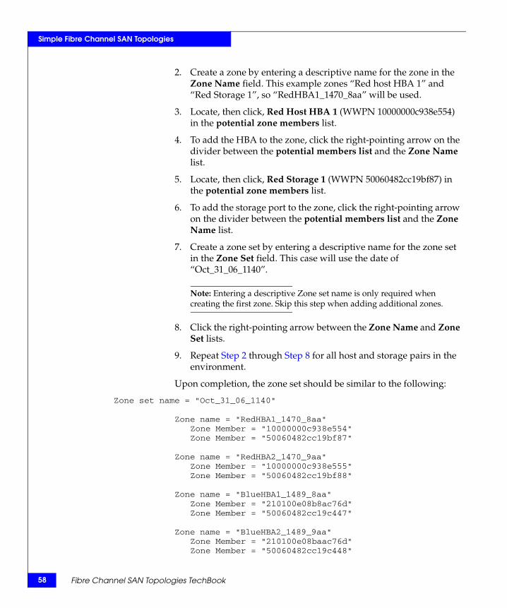
58
Simple Fibre Channel SAN Topologies
2. Create a zone by entering a descriptive name for the zone in the Zone Name field. This example zones “Red host HBA 1” and “Red Storage 1”, so “RedHBA1_1470_8aa” will be used.
3. Locate, then click, Red Host HBA 1 (WWPN 10000000c938e554) in the potential zone members list.
4. To add the HBA to the zone, click the right-pointing arrow on the divider between the potential members list and the Zone Name list.
5. Locate, then click, Red Storage 1 (WWPN 50060482cc19bf87) in the potential zone members list.
6. To add the storage port to the zone, click the right-pointing arrow on the divider between the potential members list and the Zone Name list.
7. Create a zone set by entering a descriptive name for the zone set in the Zone Set field. This case will use the date of “Oct_31_06_1140”.
Note: Entering a descriptive Zone set name is only required when creating the first zone. Skip this step when adding additional zones.
8. Click the right-pointing arrow between the Zone Name and Zone Set lists.
9. Repeat Step 2 through Step 8 for all host and storage pairs in the environment.
Upon completion, the zone set should be similar to the following:
Zone set name = "Oct_31_06_1140"
Zone name = "RedHBA1_1470_8aa"Zone Member = "10000000c938e554"Zone Member = "50060482cc19bf87"
Zone name = "RedHBA2_1470_9aa"Zone Member = "10000000c938e555"Zone Member = "50060482cc19bf88"
Zone name = "BlueHBA1_1489_8aa"Zone Member = "210100e08b8ac76d"Zone Member = "50060482cc19c447"
Zone name = "BlueHBA2_1489_9aa"Zone Member = "210100e08baac76d"Zone Member = "50060482cc19c448"
Fibre Channel SAN Topologies TechBook
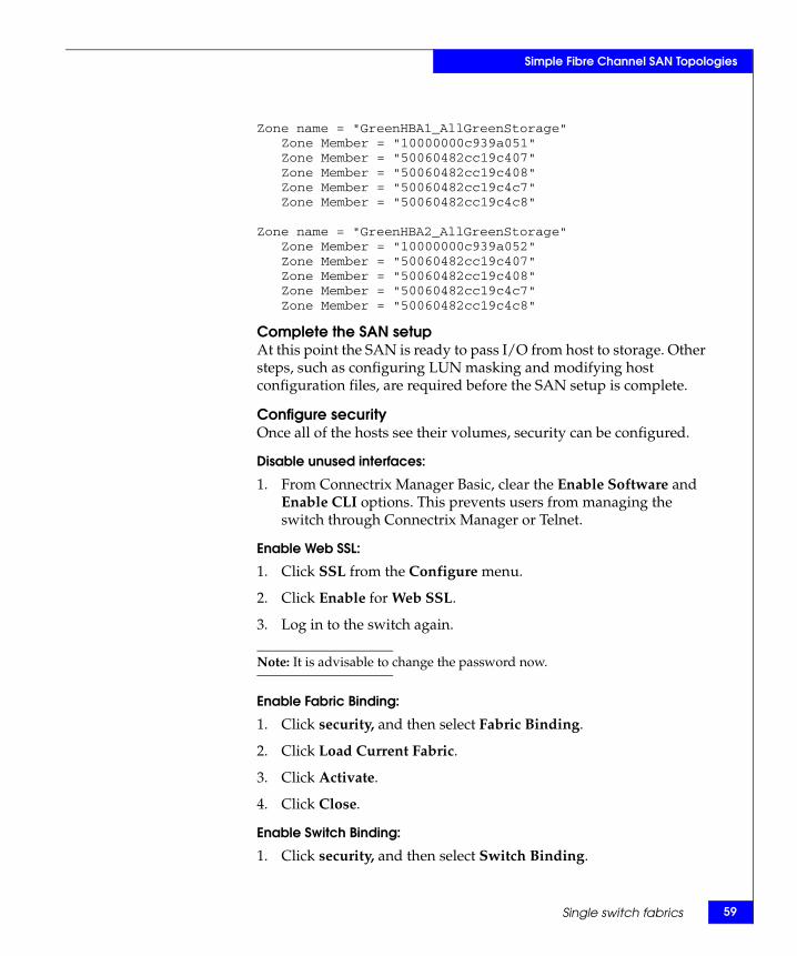
Simple Fibre Channel SAN Topologies
Zone name = "GreenHBA1_AllGreenStorage"Zone Member = "10000000c939a051"Zone Member = "50060482cc19c407"Zone Member = "50060482cc19c408"Zone Member = "50060482cc19c4c7"Zone Member = "50060482cc19c4c8"
Zone name = "GreenHBA2_AllGreenStorage"Zone Member = "10000000c939a052"Zone Member = "50060482cc19c407"Zone Member = "50060482cc19c408"Zone Member = "50060482cc19c4c7"Zone Member = "50060482cc19c4c8"
Complete the SAN setupAt this point the SAN is ready to pass I/O from host to storage. Other steps, such as configuring LUN masking and modifying host configuration files, are required before the SAN setup is complete.
Configure securityOnce all of the hosts see their volumes, security can be configured.
Disable unused interfaces:
1. From Connectrix Manager Basic, clear the Enable Software and Enable CLI options. This prevents users from managing the switch through Connectrix Manager or Telnet.
Enable Web SSL:
1. Click SSL from the Configure menu.
2. Click Enable for Web SSL.
3. Log in to the switch again.
Note: It is advisable to change the password now.
Enable Fabric Binding:
1. Click security, and then select Fabric Binding.
2. Click Load Current Fabric.
3. Click Activate.
4. Click Close.
Enable Switch Binding:
1. Click security, and then select Switch Binding.
Single switch fabrics 59
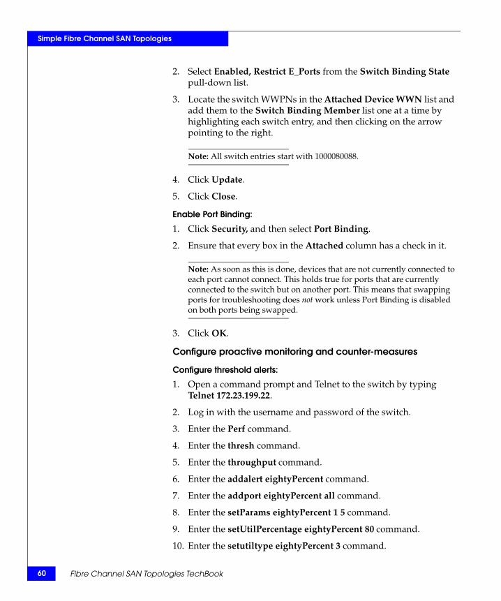
60
Simple Fibre Channel SAN Topologies
2. Select Enabled, Restrict E_Ports from the Switch Binding State pull-down list.
3. Locate the switch WWPNs in the Attached Device WWN list and add them to the Switch Binding Member list one at a time by highlighting each switch entry, and then clicking on the arrow pointing to the right.
Note: All switch entries start with 1000080088.
4. Click Update.
5. Click Close.
Enable Port Binding:
1. Click Security, and then select Port Binding.
2. Ensure that every box in the Attached column has a check in it.
Note: As soon as this is done, devices that are not currently connected to each port cannot connect. This holds true for ports that are currently connected to the switch but on another port. This means that swapping ports for troubleshooting does not work unless Port Binding is disabled on both ports being swapped.
3. Click OK.
Configure proactive monitoring and counter-measures
Configure threshold alerts:
1. Open a command prompt and Telnet to the switch by typing Telnet 172.23.199.22.
2. Log in with the username and password of the switch.
3. Enter the Perf command.
4. Enter the thresh command.
5. Enter the throughput command.
6. Enter the addalert eightyPercent command.
7. Enter the addport eightyPercent all command.
8. Enter the setParams eightyPercent 1 5 command.
9. Enter the setUtilPercentage eightyPercent 80 command.
10. Enter the setutiltype eightyPercent 3 command.
Fibre Channel SAN Topologies TechBook
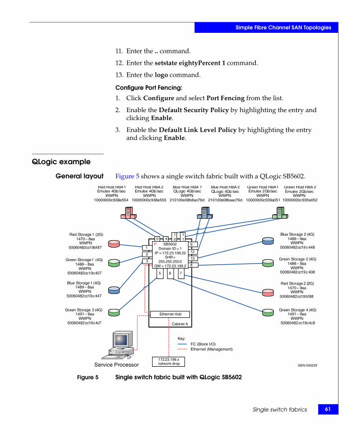
Simple Fibre Channel SAN Topologies
11. Enter the .. command.
12. Enter the setstate eightyPercent 1 command.
13. Enter the logo command.
Configure Port Fencing:
1. Click Configure and select Port Fencing from the list.
2. Enable the Default Security Policy by highlighting the entry and clicking Enable.
3. Enable the Default Link Level Policy by highlighting the entry and clicking Enable.
QLogic example
General layout Figure 5 shows a single switch fabric built with a QLogic SB5602.
Figure 5 Single switch fabric built with QLogic SB5602
GEN-000235
Key:
172 . 23 . 199 . x network drop
Cabinet A
Service Processor
Ethernet Hub
Red Host HBA 1 Emulex 4 Gb / sec
WWPN 10000000 c 938 e 554
Red Host HBA 2 Emulex 4 Gb / sec
WWPN 10000000 c 938 e 555
Green Host HBA 1 Emulex 2 Gb / sec
WWPN 10000000 c 939 a 051
Green Host HBA 2 Emulex 2 Gb / sec
WWPN 10000000 c 939 a 052
Blue Host HBA 1QLogic 4 Gb / sec
WWPN 210100 e 08 b 8 ac 76 d
Blue Host HBA 2 QLogic 4 Gb / sec
WWPN 210100 e 08 baac 76 d
Red Storage 2 (2G)1470 – 9aa
WWPN50060482cc19bf88
Red Storage 1 (2G)1470 – 8 aa
WWPN 50060482 cc 19 bf 87
Green Storage 1 ( 4 G ) 1488 – 8 aa
WWPN 50060482 cc 19 c 407
Green Storage 2 (4G)1488 – 9aa
WWPN50060482cc19c408
Blue Storage 1 ( 4 G ) 1489 – 8 aa
WWPN 50060482 cc 19 c 447
Blue Storage 2 (4G)1489 – 9aa
WWPN50060482cc19c448
Green Storage 3 ( 4 G ) 1491 – 8 aa
WWPN 50060482 cc 19 c 4 c 7
Green Storage 4 (4G)1491 – 9aa
WWPN50060482cc19c4c8
0 4
9
12
11
10
5 6 7
13
8
1
2
3
FC (Block I/O) Ethernet (Management)
SB5602Domain ID = 1
IP = 172 . 23 . 199 . 22 SnM =
255 . 255 . 255 . 0 GW = 172 . 23 . 199 . 2
P
Single switch fabrics 61
62
Simple Fibre Channel SAN Topologies
Best practices For general information on best practices in single switch fabrics, refer to “Best practices” on page 23. For QLogic-specific best practices, refer to “QLogic” on page 29.
Host and storagelayout
In this case study, a SANbox 5602 is utilized. Since the SANbox 5602 is a switch-on-a-chip (single Agate 2 ASIC) type of architecture, the host and storage ports can be placed anywhere. No special considerations need to be made in regards to port placement for performance or HA related issues.
For general information on host and storage layout in single switch fabrics, refer to “Host and storage layout” on page 30.
Switch and fabricmanagement
For general information on switch and fabric management in single switch fabrics, refer to “Switch and fabric management” on page 32. For QLogic-specific information, refer to “QLogic” on page 29.
Security For QLogic security information that may be applicable, refer to “Security” on page 109.
For general information on security in single switch fabrics, refer to “Security” on page 36.
Setting up thistopology
Assumptions specific to this case study:
◆ The QLogic SB5602 switches are installed in a customer-supplied cabinet.
For switch installation guidelines, refer to the Sections 3 and 4: Planning and Installation for an SB5602 switch in the Cisco documentation located at http://www.qlogic.com.
◆ The customer has provided the proper power receptacles.
The power requirements for the SB5602 are 1 Amp at 100VAC or 0.5 Amp at 240VAC. For cabinet power requirements, refer to the customer-supplied cabinet Setup Manual, if any.
◆ The switch has not been connected to the power source and is not powered on.
◆ Do not use the serial port. Program IP addresses with the network interface.
◆ Network drop, IP addresses, subnet mask, and gateway have been provided by the customer.
◆ License keys have been obtained.
Fibre Channel SAN Topologies TechBook
Simple Fibre Channel SAN Topologies
Note: To obtain the license key, go to the URL listed on the transaction code certificate that shipped with the product.
◆ The customer has provided a server to be used to configure the switches.
◆ One interface from the customer-supplied server is directly connected to the FC switch using a crossover cable and this interface has an IP address of 10.0.0.253.
◆ The customer has provided a temporary password to be used as the default password when configuring the IP address.
◆ The QLogic CLI commands are used to configure this switch.
Note: The SANsurfer switch manager will be used in the QLogic case study for configuring a two switch fabric (refer to “QLogic example” on page 108).
Configure the IP address
Note: QLogic switches ship with a default IP address of 10.0.0.1.
To configure the IP address:
1. Power up the switch by connecting the power cords to the power receptacles provided by the customer.
2. Open a command prompt and ping the IP address of 10.0.0.1.
• If you get a response, continue at step 2.
• If you do not get a response, you can either hard reset the switch (verify that the input power LED is illuminated, the heartbeat LED is blinking, and that the system fault LED is not on), or configure the IP address using the serial port.
Note: See the installation and service manuals for more information about configuring the IP address using the serial port.
3. Log in to a switch using Telnet. Open a command line window on the workstation and enter the Telnet command followed by the switch default IP address:
# telnet 10.0.0.1
4. A Telnet window for the switch opens, prompting for a login.
Single switch fabrics 63
64
Simple Fibre Channel SAN Topologies
5. Enter the default username, password and authority (if prompted), as admin, password, and Admin, and then press Enter.
IMPORTANT!It is strongly recommended that when prompted to change the password, you change it to a password that was provided by the customer.
6. Commands related to switch configuration are available only within the admin session. Start an admin session by issuing the admin start command at the switch prompt.
7. Run the set setup system command at the switch prompt to change the system configuration settings. The system configuration fields display.
8. For each parameter, a new value can be entered as specified in Step 9, or press Enter to accept the current or default value shown in brackets. If you want to terminate this process before reaching the end of the list, press q or Q, and then Enter.
9. Enter the following new values for the parameter fields listed on issuing the set setup system command in order to configure the switch IP address for remote logging:
Eth0Network Discovery [Static ]Eth0NetworkAddress [172.23.199.22 ]Eth0NetworkMask [255.255.255.0 ] Eth0GatewayAddress [172.23.199.2 ]Press q or Q, then Enter.
Note: The switch Telnet window might close since the IP address of the switch has just changed and you are unable to connect to the switch at its old IP address any longer.
Configure FC switches
To configure the FC switches:
1. Set the switch name and fabric parameters.
a. Enter the admin session by issuing the admin start command at switch prompt.
b. Issue the set switch config command.
Fibre Channel SAN Topologies TechBook
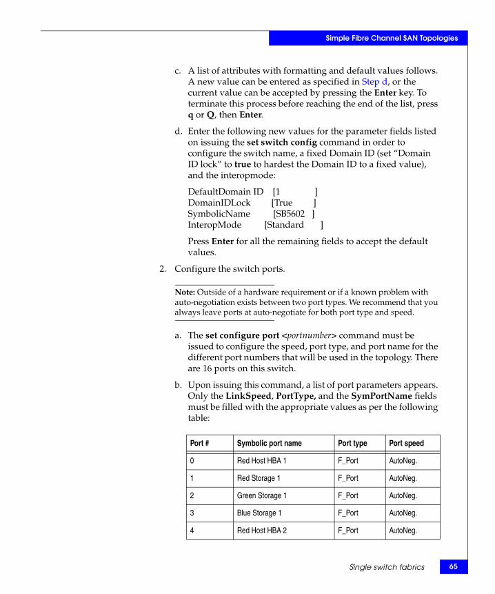
Simple Fibre Channel SAN Topologies
c. A list of attributes with formatting and default values follows. A new value can be entered as specified in Step d, or the current value can be accepted by pressing the Enter key. To terminate this process before reaching the end of the list, press q or Q, then Enter.
d. Enter the following new values for the parameter fields listed on issuing the set switch config command in order to configure the switch name, a fixed Domain ID (set “Domain ID lock” to true to hardest the Domain ID to a fixed value), and the interopmode:
DefaultDomain ID [1 ]DomainIDLock [True ]SymbolicName [SB5602 ]InteropMode [Standard ]
Press Enter for all the remaining fields to accept the default values.
2. Configure the switch ports.
Note: Outside of a hardware requirement or if a known problem with auto-negotiation exists between two port types. We recommend that you always leave ports at auto-negotiate for both port type and speed.
a. The set configure port <portnumber> command must be issued to configure the speed, port type, and port name for the different port numbers that will be used in the topology. There are 16 ports on this switch.
b. Upon issuing this command, a list of port parameters appears. Only the LinkSpeed, PortType, and the SymPortName fields must be filled with the appropriate values as per the following table:
Port # Symbolic port name Port type Port speed
0 Red Host HBA 1 F_Port AutoNeg.
1 Red Storage 1 F_Port AutoNeg.
2 Green Storage 1 F_Port AutoNeg.
3 Blue Storage 1 F_Port AutoNeg.
4 Red Host HBA 2 F_Port AutoNeg.
Single switch fabrics 65
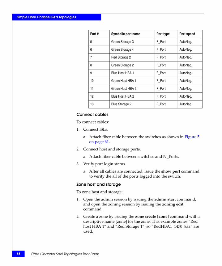
66
Simple Fibre Channel SAN Topologies
Connect cables
To connect cables:
1. Connect ISLs.
a. Attach fiber cable between the switches as shown in Figure 5 on page 61.
2. Connect host and storage ports.
a. Attach fiber cable between switches and N_Ports.
3. Verify port login status.
a. After all cables are connected, issue the show port command to verify the all of the ports logged into the switch.
Zone host and storage
To zone host and storage:
1. Open the admin session by issuing the admin start command, and open the zoning session by issuing the zoning edit command.
2. Create a zone by issuing the zone create [zone] command with a descriptive name [zone] for the zone. This example zones “Red host HBA 1” and “Red Storage 1”, so “RedHBA1_1470_8aa” are used.
5 Green Storage 3 F_Port AutoNeg.
6 Green Storage 4 F_Port AutoNeg.
7 Red Storage 2 F_Port AutoNeg.
8 Green Storage 2 F_Port AutoNeg.
9 Blue Host HBA 1 F_Port AutoNeg.
10 Green Host HBA 1 F_Port AutoNeg.
11 Green Host HBA 2 F_Port AutoNeg.
12 Blue Host HBA 2 F_Port AutoNeg.
13 Blue Storage 2 F_Port AutoNeg.
Port # Symbolic port name Port type Port speed
Fibre Channel SAN Topologies TechBook
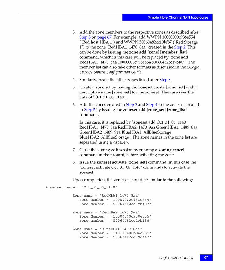
Simple Fibre Channel SAN Topologies
3. Add the zone members to the respective zones as described after Step 8 on page 67. For example, add WWPN 10000000c938e554 ("Red host HBA 1") and WWPN 50060482cc19bf87 ("Red Storage 1") to the zone "RedHBA1_1470_8aa" created in the Step 2. This can be done by issuing the zone add [zone] [member_list] command, which in this case will be replaced by "zone add RedHBA1_1470_8aa 10000000c938e554 50060482cc19bf87". The member list can also take other formats as discussed in the QLogic SB5602 Switch Configuration Guide.
4. Similarly, create the other zones listed after Step 8.
5. Create a zone set by issuing the zoneset create [zone_set] with a descriptive name [zone_set] for the zoneset. This case uses the date of "Oct_31_06_1140".
6. Add the zones created in Step 3 and Step 4 to the zone set created in Step 5 by issuing the zoneset add [zone_set] [zone_list] command.
In this case, it is replaced by "zoneset add Oct_31_06_1140 RedHBA1_1470_8aa RedHBA2_1470_9aa GreenHBA1_1489_8aa GreenHBA2_1489_9aa BlueHBA1_AllBlueStorage BlueHBA2_AllBlueStorage". The zone names in the zone list are separated using a <space>.
7. Close the zoning edit session by running a zoning cancel command at the prompt, before activating the zone.
8. Issue the zoneset activate [zone_set] command (in this case the "zoneset activate Oct_31_06_1140" command) to activate the zoneset.
Upon completion, the zone set should be similar to the following:
Zone set name = "Oct_31_06_1140"
Zone name = "RedHBA1_1470_8aa"Zone Member = "10000000c938e554"Zone Member = "50060482cc19bf87"
Zone name = "RedHBA2_1470_9aa"Zone Member = "10000000c938e555"Zone Member = "50060482cc19bf88"
Zone name = "BlueHBA1_1489_8aa"Zone Member = "210100e08b8ac76d"Zone Member = "50060482cc19c447"
Single switch fabrics 67
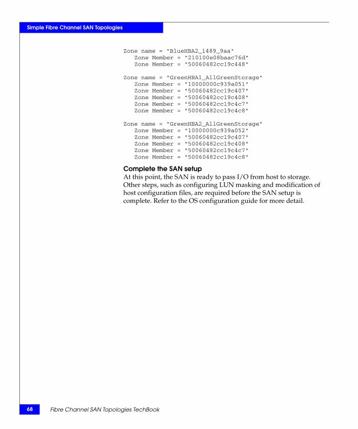
68
Simple Fibre Channel SAN Topologies
Zone name = "BlueHBA2_1489_9aa"Zone Member = "210100e08baac76d"Zone Member = "50060482cc19c448"
Zone name = "GreenHBA1_AllGreenStorage"Zone Member = "10000000c939a051"Zone Member = "50060482cc19c407"Zone Member = "50060482cc19c408"Zone Member = "50060482cc19c4c7"Zone Member = "50060482cc19c4c8"
Zone name = "GreenHBA2_AllGreenStorage"Zone Member = "10000000c939a052"Zone Member = "50060482cc19c407"Zone Member = "50060482cc19c408"Zone Member = "50060482cc19c4c7"Zone Member = "50060482cc19c4c8"
Complete the SAN setupAt this point, the SAN is ready to pass I/O from host to storage. Other steps, such as configuring LUN masking and modification of host configuration files, are required before the SAN setup is complete. Refer to the OS configuration guide for more detail.
Fibre Channel SAN Topologies TechBook
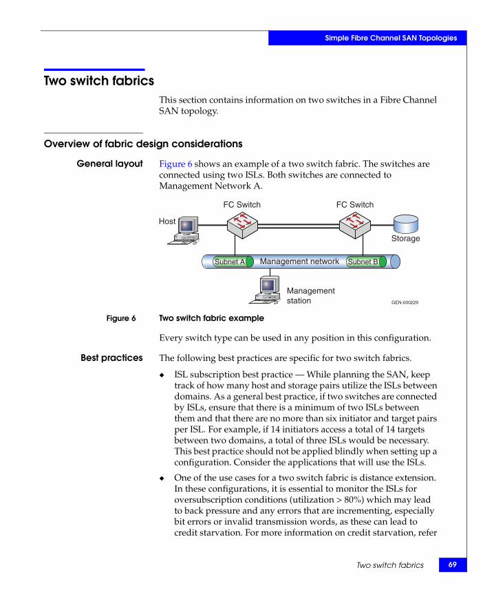
Simple Fibre Channel SAN Topologies
Two switch fabricsThis section contains information on two switches in a Fibre Channel SAN topology.
Overview of fabric design considerations
General layout Figure 6 shows an example of a two switch fabric. The switches are connected using two ISLs. Both switches are connected to Management Network A.
Figure 6 Two switch fabric example
Every switch type can be used in any position in this configuration.
Best practices The following best practices are specific for two switch fabrics.
◆ ISL subscription best practice — While planning the SAN, keep track of how many host and storage pairs utilize the ISLs between domains. As a general best practice, if two switches are connected by ISLs, ensure that there is a minimum of two ISLs between them and that there are no more than six initiator and target pairs per ISL. For example, if 14 initiators access a total of 14 targets between two domains, a total of three ISLs would be necessary. This best practice should not be applied blindly when setting up a configuration. Consider the applications that will use the ISLs.
◆ One of the use cases for a two switch fabric is distance extension. In these configurations, it is essential to monitor the ISLs for oversubscription conditions (utilization > 80%) which may lead to back pressure and any errors that are incrementing, especially bit errors or invalid transmission words, as these can lead to credit starvation. For more information on credit starvation, refer
Management network
GEN-000229
FC Switch FC Switch
Host
Storage
Managementstation
Subnet A Subnet B
Two switch fabrics 69
70
Simple Fibre Channel SAN Topologies
to “Buffer-to-buffer credit information” in the Extended Distance Technologies TechBook, available through the E-Lab Interoperability Navigator, Topology Resource Center tab, at http://elabnavigator.EMC.com. See the individual case studies below for information on how to configure in each environment.
For general information on best practices in all SANs, refer to “Best practices” on page 23.
Host and storagelayout
Specific information for two switch fabrics follows.
◆ In the two switch fabric examples used in this section, hosts and storage can be connected to either switch, but should be connected to the same switch when possible. A notable exception to this is in a distance extension environment when the two switches are used to aggregate many different connections over an ISL and provide additional BB_Credit (buffer-to-buffer credit). In this configuration, the whole point of having two switches is to use the ISL.
For general information on host and storage layout in all SANs, refer to “Host and storage layout” on page 30.
Switch and fabricmanagement
Specific information for two switch fabrics follows.
◆ All management applications can be used to monitor this environment.
For general information on switch and fabric management in all SANs, refer to “Switch and fabric management” on page 32.
Security For general information on security in all SANs, refer to “Security” on page 36.
Fibre Channel SAN Topologies TechBook
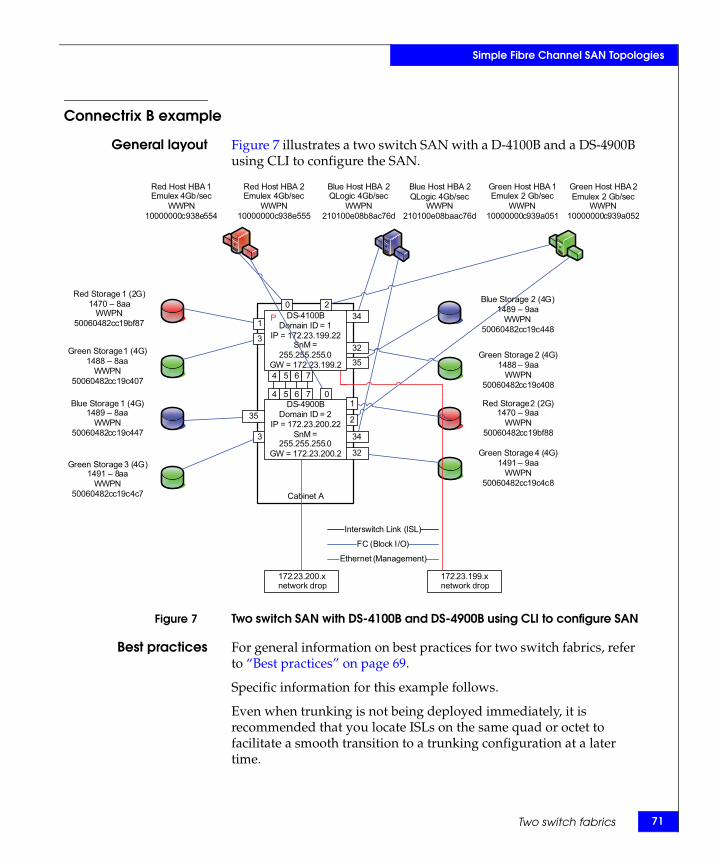
Simple Fibre Channel SAN Topologies
Connectrix B example
General layout Figure 7 illustrates a two switch SAN with a D-4100B and a DS-4900B using CLI to configure the SAN.
Figure 7 Two switch SAN with DS-4100B and DS-4900B using CLI to configure SAN
Best practices For general information on best practices for two switch fabrics, refer to “Best practices” on page 69.
Specific information for this example follows.
Even when trunking is not being deployed immediately, it is recommended that you locate ISLs on the same quad or octet to facilitate a smooth transition to a trunking configuration at a later time.
DS-4100BDomain ID = 1
IP = 172.23.199.22SnM =
255.255.255.0GW = 172.23.199.2
DS-4900BDomain ID = 2
IP = 172.23.200.22SnM =
255.255.255.0GW = 172.23.200.2
172.23.200.x network drop
FC (Block I/O)
Ethernet (Management)
Interswitch Link (ISL)
Cabinet A
172.23.199.x network drop
Red Host HBA 1Emulex 4Gb/sec
WWPN10000000c938e554
Red Host HBA 2Emulex 4Gb/sec
WWPN10000000c938e555
Green Host HBA 1Emulex 2 Gb/sec
WWPN10000000c939a051
Green Host HBA 2Emulex 2 Gb/sec
WWPN10000000c939a052
Blue Host HBA 2QLogic 4Gb/sec
WWPN210100e08b8ac76d
Blue Host HBA 2QLogic 4Gb/sec
WWPN210100e08baac76d
Red Storage 2 (2G)1470 – 9aa
WWPN50060482cc19bf88
Red Storage 1 (2G)1470 – 8aa
WWPN50060482cc19bf87
Green Storage 1 (4G)1488 – 8aa
WWPN50060482cc19c407
Green Storage 2 (4G)1488 – 9aa
WWPN50060482cc19c408
Blue Storage 1 (4G)1489 – 8aa
WWPN50060482cc19c447
Blue Storage 2 (4G)1489 – 9aa
WWPN50060482cc19c448
Green Storage 3 (4G)1491 – 8aa
WWPN50060482cc19c4c7
Green Storage 4 (4G)1491 – 9aa
WWPN50060482cc19c4c8
034
2
4 0
34
32
1
32
35
1
3
35
3
P
4
2
5
5
6
6
7
7
Two switch fabrics 71
72
Simple Fibre Channel SAN Topologies
For more Connectrix B specific best practices, refer to “Connectrix B” on page 26.
Host and storagelayout
Both hosts and storage can be placed anywhere on the SAN. Connectrix B groups ASIC controlled port groups by octet on the DS-4900B. In some circumstances, it may be recommended to connect both host and storage to these groupings. This eliminates frames traveling through the backplane of the switch to reach their destination.
For general information on host and storage layout for two switch fabrics, refer to “Host and storage layout” on page 30.
Switch and fabricmanagement
In this example, the CLI (Command Line Interface) is used to create a two switch fabric consisting of a DS-4900B and a DS-4100B. Once the two switch fabric has been connected, three hosts and their associated storage will be attached and properly configured.
For general information on switch and fabric management for two switch fabrics, refer to “Switch and fabric management” on page 32.
Security For general information on security for two switch fabrics, refer to “Security” on page 36. For more information on security, refer to the Building Secure SANs TechBook, available through the E-Lab Interoperability Navigator, Topology Resource Center tab, at http://elabnavigator.EMC.com.
Setting up thistopology
Assumptions specific to this case study:
◆ The Fibre Channel switches are installed in an EMC-supplied cabinet.
• For installation instructions, see Connectrix EC-1500 Cabinet Installation and Setup Manual, which can be accessed from Powerlink.
◆ Redundant power sources are available.
• For switch power requirements, refer to the EMC Connectrix SAN Products Data Reference Manual, available through the E-Lab Interoperability Navigator, Topology Resource Center tab, at http://elabnavigator.EMC.com.
◆ A laptop is available with the following specifications:
• Running some version of Windows
• HyperTerminal is installed
Fibre Channel SAN Topologies TechBook
Simple Fibre Channel SAN Topologies
• Laptop serial ports are DB-9 connections and COM1 will be used to configure the switch IP addresses
◆ A serial cable (straight through) and an Ethernet cable (crossover) are available.
◆ Network drops, IP addresses, subnet mask, and gateway have been provided by the customer.
◆ SFP transceivers and compatible fiber cables are available as required.
◆ Access to an FTP server, for backing up (uploading) or downloading the switch configuration is available.
◆ License keys have been obtained.
• Go to the URL listed on the transaction code certificate that shipped with the product to get the license key.
◆ The customer has provided a temporary password that will be used as the default password when configuring the IP address.
◆ Trunking licenses have been purchased by the Customer for both switches and are available for installation.
Configure the IP address
To configure the IP address:
Note: The DS-4900B uses an RJ-45 connector for the serial port instead of a DB-9 connector. Because of this, an RJ-45 serial cable (10-ft (3 m) long) is shipped with switch in addition to an RJ-45 to DB-9 adaptor. Use these to configure the IP address on the DS-4900B. The DS-4100B provides an older style DB-9 connector for the serial port interface.
1. Attach the straight through (DB-9 to DB-9) serial cable between the serial port on the DS-4100B and the RS-232 serial port on the management PC (COM1). The serial cable is wired with only pins 2, 3, and 5 wired straight through.
2. Power up the switch by connecting the power cords to the power receptacles provided by the customer. Make sure that all power cords are connected to the switch for maximum redundancy.
Note: Both power supplies must be connected in order to bring the switch online.
Two switch fabrics 73
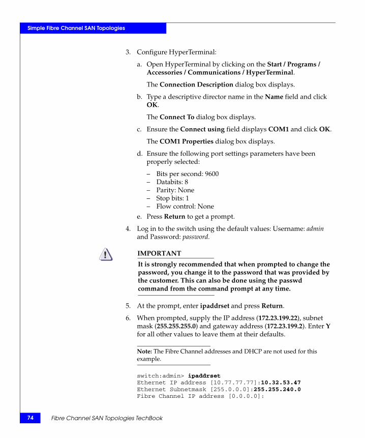
74
Simple Fibre Channel SAN Topologies
3. Configure HyperTerminal:
a. Open HyperTerminal by clicking on the Start / Programs / Accessories / Communications / HyperTerminal.
The Connection Description dialog box displays.
b. Type a descriptive director name in the Name field and click OK.
The Connect To dialog box displays.
c. Ensure the Connect using field displays COM1 and click OK.
The COM1 Properties dialog box displays.
d. Ensure the following port settings parameters have been properly selected:
– Bits per second: 9600– Databits: 8– Parity: None– Stop bits: 1– Flow control: None
e. Press Return to get a prompt.
4. Log in to the switch using the default values: Username: admin and Password: password.
IMPORTANT!It is strongly recommended that when prompted to change the password, you change it to the password that was provided by the customer. This can also be done using the passwd command from the command prompt at any time.
5. At the prompt, enter ipaddrset and press Return.
6. When prompted, supply the IP address (172.23.199.22), subnet mask (255.255.255.0) and gateway address (172.23.199.2). Enter Y for all other values to leave them at their defaults.
Note: The Fibre Channel addresses and DHCP are not used for this example.
switch:admin> ipaddrsetEthernet IP address [10.77.77.77]:10.32.53.47Ethernet Subnetmask [255.0.0.0]:255.255.240.0Fibre Channel IP address [0.0.0.0]:
Fibre Channel SAN Topologies TechBook
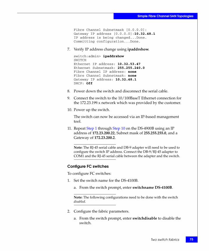
Simple Fibre Channel SAN Topologies
Fibre Channel Subnetmask [0.0.0.0]:Gateway IP address [0.0.0.0]:10.32.48.1IP address is being changed...Done.Committing configuration...Done.
7. Verify IP address change using ipaddrshow.
switch:admin> ipaddrshowSWITCHEthernet IP address: 10.32.53.47Ethernet Subnetmask: 255.255.240.0Fibre Channel IP address: noneFibre Channel Subnetmask: noneGateway IP address: 10.32.48.1DHCP: Off
8. Power down the switch and disconnect the serial cable.
9. Connect the switch to the 10/100BaseT Ethernet connection for the 172.23.199.x network which was provided by the customer.
10. Power up the switch.
The switch can now be accessed via an IP-based management tool.
11. Repeat Step 1 through Step 10 on the DS-4900B using an IP address of 172.23.200.22, Subnet mask of 255.255.255.0, and a Gateway of 172.23.200.2.
Note: The RJ-45 serial cable and DB-9 adapter will need to be used to configure the switch IP address. Connect the DB-9/RJ-45 adapter to COM1 and the RJ-45 serial cable between the adapter and the switch.
Configure FC switches
To configure FC switches:
1. Set the switch name for the DS-4100B.
a. From the switch prompt, enter switchname DS-4100B.
Note: The following configurations need to be done with the switch disabled.
2. Configure the fabric parameters.
a. From the switch prompt, enter switchdisable to disable the switch.
Two switch fabrics 75
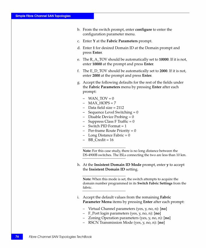
76
Simple Fibre Channel SAN Topologies
b. From the switch prompt, enter configure to enter the configuration parameter menu.
c. Enter Y at the Fabric Parameters prompt.
d. Enter 1 for desired Domain ID at the Domain prompt and press Enter.
e. The R_A_TOV should be automatically set to 10000. If it is not, enter 10000 at the prompt and press Enter.
f. The E_D_TOV should be automatically set to 2000. If it is not, enter 2000 at the prompt and press Enter.
g. Accept the following defaults for the rest of the fields under the Fabric Parameters menu by pressing Enter after each prompt:
– WAN_TOV = 0– MAX_HOPS = 7– Data field size = 2112– Sequence Level Switching = 0– Disable Device Probing = 0– Suppress Class F Traffic = 0– Switch PID Format = 1– Per-frame Route Priority = 0– Long Distance Fabric = 0– BB_Credit = 16
Note: For this case study, there is no long distance between the DS-4900B switches. The ISLs connecting the two are less than 10 km.
h. At the Insistent Domain ID Mode prompt, enter y to accept the Insistent Domain ID setting.
Note: When this mode is set, the switch attempts to acquire the domain number programmed in its Switch Fabric Settings from the fabric.
i. Accept the default values from the remaining Fabric Parameter Menu items by pressing Enter after each prompt:
– Virtual Channel parameters (yes, y, no, n): [no]– F_Port login parameters (yes, y, no, n): [no]– Zoning Operation parameters (yes, y, no, n): [no]– RSCN Transmission Mode (yes, y, no, n): [no]
Fibre Channel SAN Topologies TechBook

Simple Fibre Channel SAN Topologies
– Arbitrated Loop parameters (yes, y, no, n): [no]– System services (yes, y, no, n): [no]– Portlog events enable (yes, y, no, n): [no]– ssl attributes (yes, y, no, n): [no]– http attributes (yes, y, no, n): [no]– snmp attributes (yes, y, no, n): [no]– rpcd attributes (yes, y, no, n): [no]– cfgload attributes (yes, y, no, n): [no]– web tools attributes (yes, y, no, n): [no]
3. Install the necessary licenses.
Note: In this case, the only license to be installed will be the trunking license.
a. From the switch prompt, enter licenseadd <license for this switch>.
Example:
switch:admin> licenseadd byeSRbdzyQkzfTS0
Note: To enable trunking on the switch after unlocking the license, you need to re-initialize the ports. To re-initialize the ports, you can either disable, and then re-enable, the switch or disable, and then re-enable, the affected ISL ports. Since the switch is already disabled and will be re-enabled in the next step, the explicit disabling and re-enabling of the switch and/or switch ports will not be necessary.
4. From the switch prompt, enter switchenable to enable the switch.
5. Repeat Step 1 through Step 4 for the DS-4900B using the switch name of DS-4900B and 2 for the desired Domain ID.
Verify the firmware version loaded on the switches
Run the firmwareshow command to verify the firmware version.
switch:admin> firmwareshowPrimary partition: v5.2.1aSecondary Partition: v5.2.1aswitch:admin>
Two switch fabrics 77
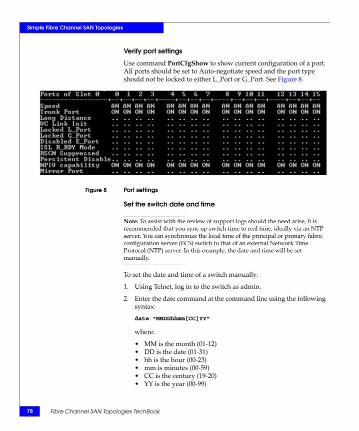
78
Simple Fibre Channel SAN Topologies
Verify port settings
Use command PortCfgShow to show current configuration of a port. All ports should be set to Auto-negotiate speed and the port type should not be locked to either L_Port or G_Port. See Figure 8.
Figure 8 Port settings
Set the switch date and time
Note: To assist with the review of support logs should the need arise, it is recommended that you sync up switch time to real time, ideally via an NTP server. You can synchronize the local time of the principal or primary fabric configuration server (FCS) switch to that of an external Network Time Protocol (NTP) server. In this example, the date and time will be set manually.
To set the date and time of a switch manually:
1. Using Telnet, log in to the switch as admin.
2. Enter the date command at the command line using the following syntax:
date "MMDDhhmm[CC]YY"
where:
• MM is the month (01-12)• DD is the date (01-31)• hh is the hour (00-23)• mm is minutes (00-59)• CC is the century (19-20)• YY is the year (00-99)
Fibre Channel SAN Topologies TechBook
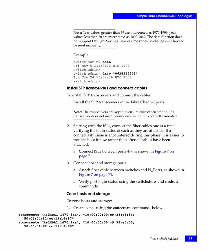
Simple Fibre Channel SAN Topologies
Note: Year values greater than 69 are interpreted as 1970-1999; year values less than 70 are interpreted as 2000-2069. The date function does not support Daylight Savings Time or time zones, so changes will have to be reset manually.
Example:
switch:admin> dateFri May 5 21:50:00 UTC 1989switch:admin>switch:admin> date "0624165203"Tue Jun 24 16:52:30 UTC 2003switch:admin>
Install SFP transceivers and connect cables
To install SFP transceivers and connect the cables:
1. Install the SFP transceivers in the Fibre Channel ports.
Note: The transceivers are keyed to ensure correct orientation. If a transceiver does not install easily, ensure that it is correctly oriented.
2. Starting with the ISLs, connect the fiber cables one at a time, verifying the login status of each as they are attached. If a connectivity issue is encountered during this phase, it is easier to troubleshoot it now rather than after all cables have been attached.
a. Connect ISLs between ports 4-7 as shown in Figure 7 on page 71.
3. Connect host and storage ports.
a. Attach fiber cable between switches and N_Ports, as shown in Figure 7 on page 71.
b. Verify port login status using the switchshow and nsshow commands.
Zone hosts and storage
To zone hosts and storage:
1. Create zones using the zonecreate commands below:
zonecreate "RedHBA1_1470_8aa", "10:00:00:00:c9:38:e5:54; 50:06:04:82:cc:19:bf:87"
zonecreate "RedHBA2_1470_9aa", "10:00:00:00:c9:38:e5:55; 50:06:04:82:cc:19:bf:88"
Two switch fabrics 79
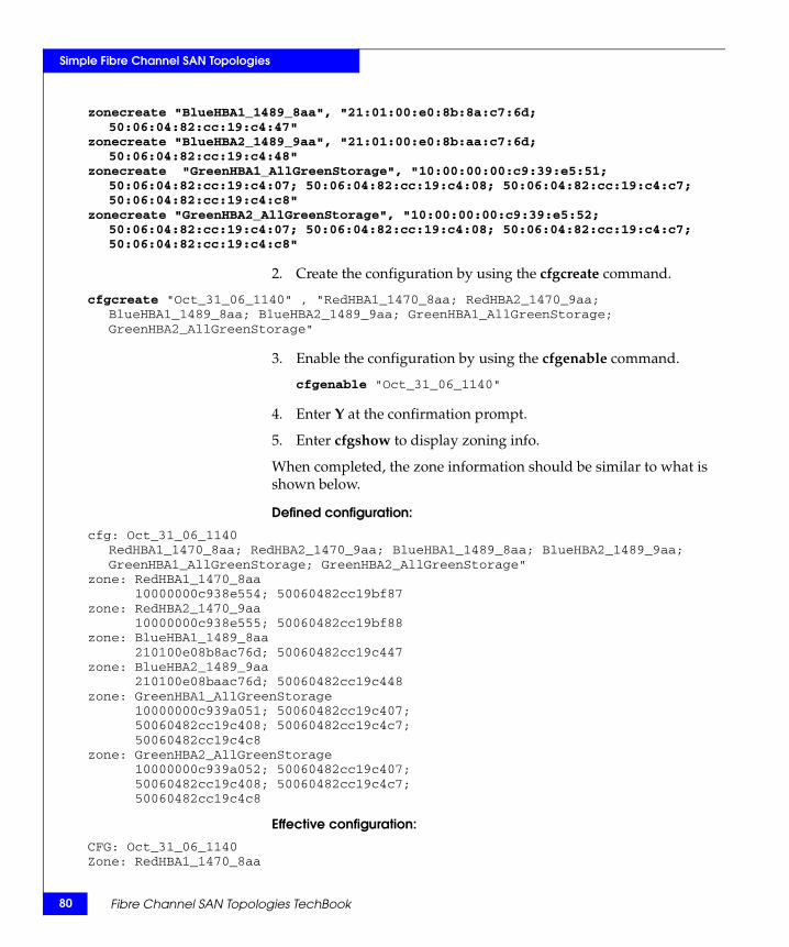
80
Simple Fibre Channel SAN Topologies
zonecreate "BlueHBA1_1489_8aa", "21:01:00:e0:8b:8a:c7:6d; 50:06:04:82:cc:19:c4:47"
zonecreate "BlueHBA2_1489_9aa", "21:01:00:e0:8b:aa:c7:6d; 50:06:04:82:cc:19:c4:48"
zonecreate "GreenHBA1_AllGreenStorage", "10:00:00:00:c9:39:e5:51; 50:06:04:82:cc:19:c4:07; 50:06:04:82:cc:19:c4:08; 50:06:04:82:cc:19:c4:c7; 50:06:04:82:cc:19:c4:c8"
zonecreate "GreenHBA2_AllGreenStorage", "10:00:00:00:c9:39:e5:52; 50:06:04:82:cc:19:c4:07; 50:06:04:82:cc:19:c4:08; 50:06:04:82:cc:19:c4:c7; 50:06:04:82:cc:19:c4:c8"
2. Create the configuration by using the cfgcreate command.
cfgcreate "Oct_31_06_1140" , "RedHBA1_1470_8aa; RedHBA2_1470_9aa; BlueHBA1_1489_8aa; BlueHBA2_1489_9aa; GreenHBA1_AllGreenStorage; GreenHBA2_AllGreenStorage"
3. Enable the configuration by using the cfgenable command.
cfgenable "Oct_31_06_1140"
4. Enter Y at the confirmation prompt.
5. Enter cfgshow to display zoning info.
When completed, the zone information should be similar to what is shown below.
Defined configuration:
cfg: Oct_31_06_1140RedHBA1_1470_8aa; RedHBA2_1470_9aa; BlueHBA1_1489_8aa; BlueHBA2_1489_9aa; GreenHBA1_AllGreenStorage; GreenHBA2_AllGreenStorage"
zone: RedHBA1_1470_8aa10000000c938e554; 50060482cc19bf87
zone: RedHBA2_1470_9aa10000000c938e555; 50060482cc19bf88
zone: BlueHBA1_1489_8aa210100e08b8ac76d; 50060482cc19c447
zone: BlueHBA2_1489_9aa210100e08baac76d; 50060482cc19c448
zone: GreenHBA1_AllGreenStorage10000000c939a051; 50060482cc19c407;50060482cc19c408; 50060482cc19c4c7;50060482cc19c4c8
zone: GreenHBA2_AllGreenStorage10000000c939a052; 50060482cc19c407;50060482cc19c408; 50060482cc19c4c7;50060482cc19c4c8
Effective configuration:
CFG: Oct_31_06_1140Zone: RedHBA1_1470_8aa
Fibre Channel SAN Topologies TechBook
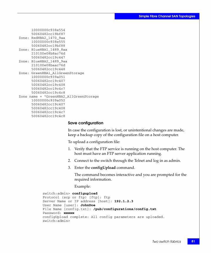
Simple Fibre Channel SAN Topologies
10000000c938e55450060482cc19bf87
Zone: RedHBA2_1470_9aa10000000c938e55550060482cc19bf88
Zone: BlueHBA1_1489_8aa210100e08b8ac76d50060482cc19c447
Zone: BlueHBA2_1489_9aa210100e08baac76d50060482cc19c448
Zone: GreenHBA1_AllGreenStorage10000000c939a05150060482cc19c40750060482cc19c40850060482cc19c4c750060482cc19c4c8
Zone name = "GreenHBA2_AllGreenStorage10000000c939a05250060482cc19c40750060482cc19c40850060482cc19c4c750060482cc19c4c8
Save configuration
In case the configuration is lost, or unintentional changes are made, keep a backup copy of the configuration file on a host computer.
To upload a configuration file:
1. Verify that the FTP service is running on the host computer. The host must have an FTP server application running.
2. Connect to the switch through the Telnet and log in as admin.
3. Enter the configUpload command.
The command becomes interactive and you are prompted for the required information.
Example:
switch:admin> configuploadProtocol (scp or ftp) [ftp]: ftpServer Name or IP address [host]: 192.1.2.3User Name [user]: JohnDoeFile Name [config.txt]: /pub/configurations/config.txtPassword: xxxxxconfigUpload complete: All config parameters are uploaded.switch:admin>
Two switch fabrics 81
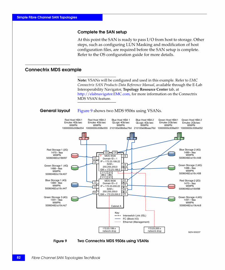
82
Simple Fibre Channel SAN Topologies
Complete the SAN setup
At this point the SAN is ready to pass I/O from host to storage. Other steps, such as configuring LUN Masking and modification of host configuration files, are required before the SAN setup is complete. Refer to the OS configuration guide for more details.
Connectrix MDS example
Note: VSANs will be configured and used in this example. Refer to EMC Connectrix SAN Products Data Reference Manual, available through the E-Lab Interoperability Navigator, Topology Resource Center tab, at http://elabnavigator.EMC.com, for more information on the Connectrix MDS VSAN feature.
General layout Figure 9 shows two MDS 9506s using VSANs.
Figure 9 Two Connectrix MDS 9506s using VSANs
GEN-000237
Key:
Domain ID = 2 IP = 172 . 23 . 200.22
SnM = 255 . 255 . 255 . 0
GW = 172 . 23 . 200. 2
172 . 23 . 199 . x network drop
Cabinet A
172 . 23 . 200 . x network drop
Red Host HBA 1 Emulex 4 Gb / sec
WWPN 10000000 c 938 e 554
Red Host HBA 2 Emulex 4 Gb / sec
WWPN 10000000 c 938 e 555
Green Host HBA 1 Emulex 2 Gb / sec
WWPN 10000000 c 939 a 051
Green Host HBA 2 Emulex 2 Gb / sec
WWPN 10000000 c 939 a 052
Blue Host HBA 1QLogic 4 Gb / sec
WWPN 210100 e 08 b 8 ac 76 d
Blue Host HBA 2 QLogic 4 Gb / sec
WWPN 210100 e 08 baac 76 d
Red Storage 2 (2G)1470 – 9aa
WWPN50060482cc19bf88
Red Storage 1 (2G)1470 – 8 aa
WWPN 50060482 cc 19 bf 87
Green Storage 1 (4G)1488 – 8 aa
WWPN 50060482 cc 19 c 407
Green Storage 2 (4G)1488 – 9aa
WWPN50060482cc19c408
Blue Storage 1 ( 4 G ) 1489 – 8 aa
WWPN 50060482 cc 19 c 447
Blue Storage 2 (4G)1489 – 9aa
WWPN50060482cc19c448
Green Storage 3 ( 4 G ) 1491 – 8 aa
WWPN 50060482 cc 19 c 4 c 7
Green Storage 4 (4G)1491 – 9aa
WWPN50060482cc19c4c8
1/2
2/3
1/4
1/1 2/1
1/1 2/1
2/4
2/5
2/3
2/2
2/4
2/2
1/3
1/5
1/3
1/2
1/4
Interswitch Link (ISL) FC (Block I/O) Ethernet (Management)
MDS 9506
MDS 9506
Domain ID = 1 IP = 172 . 23 . 199 . 22
SnM = 255 . 255 . 255 . 0
GW = 172 . 23 . 199 . 2
P
Fibre Channel SAN Topologies TechBook
Simple Fibre Channel SAN Topologies
Best practices For general information on best practices for two switch fabrics, refer to “Best practices” on page 69. Specific information for this example follows.
By default thresholds are set to 80% utilization.
Host and storagelayout
For general information on host and storage layout for two switch fabrics, refer to “Host and storage layout” on page 70. Specific information for this example follows.
Line Rate Mode cards have no special restrictions. Over-subscribed cards should be used for hosts only.
Switch and fabricmanagement
For general information on switch and fabric management for two switch fabrics, refer to “Switch and fabric management” on page 70. Specific information for this example follows.
Cisco Fabric Manager may be used for management.
Security For general information on security for two switch fabrics, refer to “Security” on page 70. Specific information for this example follows.
Use Switch Binding and Port Binding for security.
Setting up thistopology
Assumptions specific to this case study:
◆ The switches are installed in an EMC-supplied cabinet.
• For installation instructions, see Connectrix EC-1500 Cabinet Installation and Setup Manual, which can be accessed from Powerlink.
◆ The proper power receptacles have been provided by the customer.
• For switch power requirements, refer to the EMC Connectrix SAN Products Data Reference Manual, available through the E-Lab Interoperability Navigator, Topology Resource Center tab, at http://elabnavigator.EMC.com.
• For Cabinet power requirements, refer to Connectrix EC-1500 Cabinet Installation and Setup Manual which can be accessed from Powerlink.
◆ The switches have not been connected to the power source and are not powered on.
◆ Network drops, IP addresses, subnet mask, and gateway have been provided by the customer.
Two switch fabrics 83
84
Simple Fibre Channel SAN Topologies
For switch or cabinet network requirements, refer to the EMC Connectrix SAN Products Data Reference Manual, available through the E-Lab Interoperability Navigator, Topology Resource Center tab, at http://elabnavigator.EMC.com.
Note: Connectrix MDS switches can be placed on either a public or private network. There are advantages to both configurations. For more information, refer to "Public versus private" in the Networked Storage Concepts and Protocols TechBook, available through the E-Lab Interoperability Navigator, Topology Resource Center tab, at http://elabnavigator.EMC.com.In this example, it is assumed that the customer has provided two Ethernet cables and that one of them is on the 172.23.199.x network and that the other is connected to the 172.23.200.x network.
◆ The correct number of line cards have been installed into each chassis. In this case, two line cards in each chassis are required and installed in slots 1 and 2.
• For help in determining how many ports are required, refer to "Determining customer requirements" in the Networked Storage Concepts and Protocols TechBook, available through the E-Lab Interoperability Navigator, Topology Resource Center tab, at http://elabnavigator.EMC.com.
◆ License keys have been obtained.
• Go to the URL listed on the transaction code certificate that shipped with the product to get the license key.
◆ Use the laptop supplied by the installer to configure the IP addresses of the switches; this laptop has a serial DB-9 connector.
◆ Use the temporary password provided by the customer as the default password when configuring the IP address.
◆ Use Fabric Manager for VSAN setup.
Configure the IP address
To configure the IP address:
1. Power up the cabinet by connecting the power cords to the power receptacles provided by the customer.
2. Select one of the switches to configure and set the IP to 172.23.199.22.
3. Supply a network connection to the appropriate subnet.
Fibre Channel SAN Topologies TechBook
Simple Fibre Channel SAN Topologies
4. Connect to the serial port of the switch using an RS232 serial cable, with a baud rate of 9600, 8 data bits, no parity, 1 stop bit and no flow control.
The login prompt should display.
5. Log in the first time with username admin and password admin.
You should be prompted to supply a new strong password for CLI user admin.
6. For this example, select no when asked if you want to run setup.
Note: This example will start with the switch that will have a Domain ID of 1 and an IP address of 172.23.199.22.
7. Repeat above steps for each switch, supplying the appropriate IP.
CLI commands to configure the IP and gateway
◆ Switch# config terminal
Enter configuration commands, one per line.
Switch(config)# interface mgmt 0Switch(config-if)#IP address 172.23.199.22 255.255.255.0End with CNTL/Z.
◆ Switch# config terminal
Enter configuration commands, one per line.
Switch(config)# ip default-gateway 172.23.199.2End with CNTL/Z.
To authorize access on a switch for Device and Fabric Manager, run this command on every switch while supplying a username (nnn) and password (ppp):
◆ Switch#conf t
Switch(config)# snmp-server user nnn network-admin auth md5 pppSwitch(config)#endSwitch# copy running-config startup-configSwitch# exit
Installing Fabric Manager and Device Manager
To install Fabric Manager and Device Manager:
1. Open your web browser.
Two switch fabrics 85
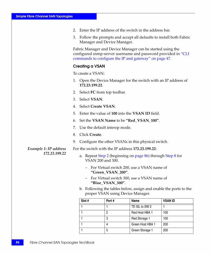
86
Simple Fibre Channel SAN Topologies
2. Enter the IP address of the switch in the address bar.
3. Follow the prompts and accept all defaults to install both Fabric Manager and Device Manager.
Fabric Manager and Device Manager can be started using the configured snmp-server username and password provided in “CLI commands to configure the IP and gateway” on page 47.
Creating a VSAN
To create a VSAN:
1. Open the Device Manager for the switch with an IP address of 172.23.199.22.
2. Select FC from top toolbar.
3. Select VSAN.
4. Select Create VSAN.
5. Enter the value of 100 into the VSAN ID field.
6. Set the VSAN Name to be “Red_VSAN_100”.
7. Use the default interop mode.
8. Click Create.
9. Configure the other VSANs in this physical switch.
Example 1: IP address172.23.199.22
For the switch with the IP address 172.23.199.22:
a. Repeat Step 2 (beginning on page 86) through Step 8 for VSAN 200 and 300.
– For Virtual switch 200, use a VSAN name of “Green_VSAN_200”.
– For Virtual switch 300, use a VSAN name of “Blue_VSAN_300”.
b. Following the tables below, assign and enable the ports to the proper VSAN using Device Manager.
Slot # Port # Name VSAN ID
1 1 TE ISL to SW 2 1
1 2 Red Host HBA 1 100
1 3 Red Storage 1 100
1 4 Green Host HBA 1 200
1 5 Green Storage 1 200
Fibre Channel SAN Topologies TechBook
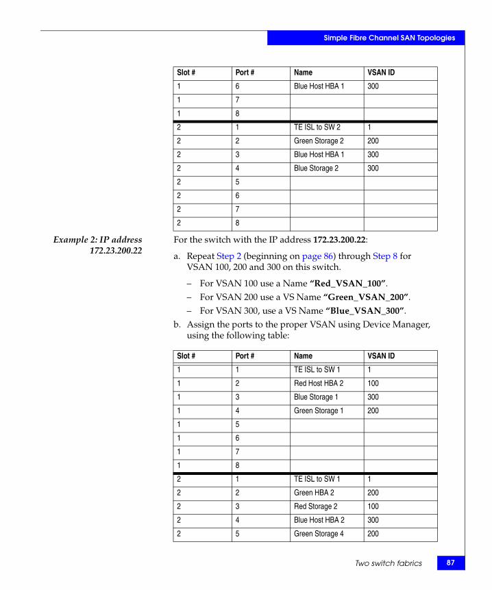
Simple Fibre Channel SAN Topologies
Example 2: IP address172.23.200.22
For the switch with the IP address 172.23.200.22:
a. Repeat Step 2 (beginning on page 86) through Step 8 for VSAN 100, 200 and 300 on this switch.
– For VSAN 100 use a Name “Red_VSAN_100”.– For VSAN 200 use a VS Name “Green_VSAN_200”.– For VSAN 300, use a VS Name “Blue_VSAN_300”.
b. Assign the ports to the proper VSAN using Device Manager, using the following table:
1 6 Blue Host HBA 1 300
1 7
1 8
2 1 TE ISL to SW 2 1
2 2 Green Storage 2 200
2 3 Blue Host HBA 1 300
2 4 Blue Storage 2 300
2 5
2 6
2 7
2 8
Slot # Port # Name VSAN ID
Slot # Port # Name VSAN ID
1 1 TE ISL to SW 1 1
1 2 Red Host HBA 2 100
1 3 Blue Storage 1 300
1 4 Green Storage 1 200
1 5
1 6
1 7
1 8
2 1 TE ISL to SW 1 1
2 2 Green HBA 2 200
2 3 Red Storage 2 100
2 4 Blue Host HBA 2 300
2 5 Green Storage 4 200
Two switch fabrics 87
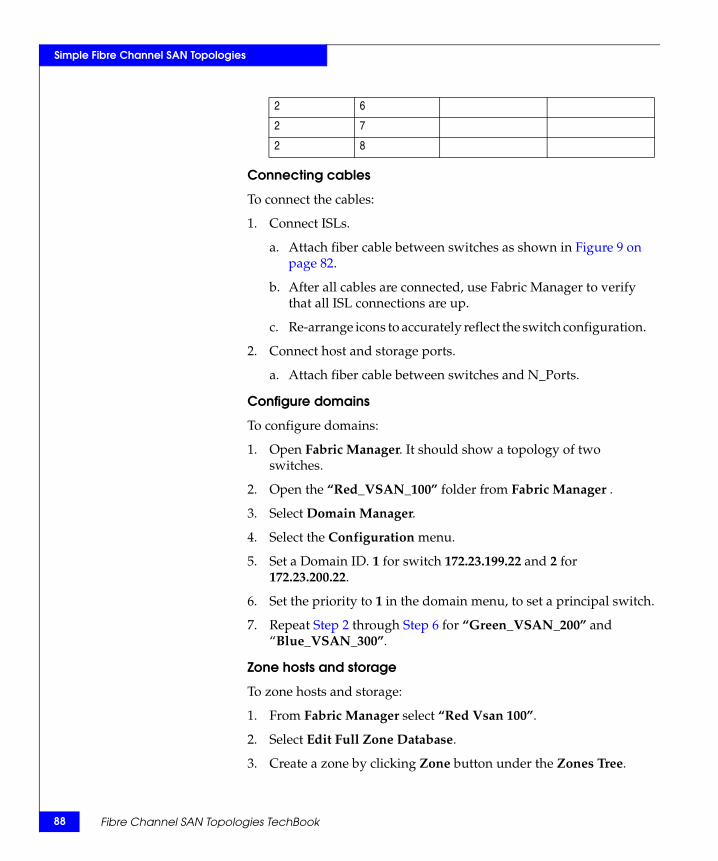
88
Simple Fibre Channel SAN Topologies
Connecting cables
To connect the cables:
1. Connect ISLs.
a. Attach fiber cable between switches as shown in Figure 9 on page 82.
b. After all cables are connected, use Fabric Manager to verify that all ISL connections are up.
c. Re-arrange icons to accurately reflect the switch configuration.
2. Connect host and storage ports.
a. Attach fiber cable between switches and N_Ports.
Configure domains
To configure domains:
1. Open Fabric Manager. It should show a topology of two switches.
2. Open the “Red_VSAN_100” folder from Fabric Manager .
3. Select Domain Manager.
4. Select the Configuration menu.
5. Set a Domain ID. 1 for switch 172.23.199.22 and 2 for 172.23.200.22.
6. Set the priority to 1 in the domain menu, to set a principal switch.
7. Repeat Step 2 through Step 6 for “Green_VSAN_200” and “Blue_VSAN_300”.
Zone hosts and storage
To zone hosts and storage:
1. From Fabric Manager select “Red Vsan 100”.
2. Select Edit Full Zone Database.
3. Create a zone by clicking Zone button under the Zones Tree.
2 6
2 7
2 8
Fibre Channel SAN Topologies TechBook

Simple Fibre Channel SAN Topologies
4. Provide a descriptive name for the zone. This example will zone “Red host HBA 1” and “Red Storage 1”, so “RedHBA1_1470_8aa” will be used. Press Enter.
5. Locate, then click, “Red Host HBA 1” (WWPN 10000000c938e554) in the Potential zone members list.
6. Click the right-pointing arrow on the divider between the Potential members list and the zones list to add the HBA to the zone.
7. Locate, then click, “Red Storage 1” (WWPN 50060482cc19bf87) in the Potential zone members list.
8. Click the right-pointing arrow on the divider between the Potential members list and the zones list to add the Storage port to the zone.
9. Repeat Step 2 through Step 7 for all host and storage pairs in the environment.
10. Create a zone set by clicking New Set under the Zone sets Tree.
11. Provide a descriptive name for the zone set. This example uses the name “RED Fabric 1”.
Add only those zones that will be necessary on Red_Fabric_1. In this case only the zone named “RedHBA1_1470_8aa” should be added to the Red_Fabric_1 zone set. Repeat for other Fabrics. When completed, you should have 5 zone sets, as shown below.
Zone set name = "Red_Fabric_1"
Zone name = "RedHBA1_1470_8aa"Zone Member = "10000000c938e554"Zone Member = "50060482cc19bf87"
Zone name = "RedHBA2_1470_9aa"Zone Member = "10000000c938e555"Zone Member = "50060482cc19bf88"
Zone set name = "Blue_Fabric_1"
Zone name = "BlueHBA1_1489_8aa"Zone Member = "210100e08b8ac76d"Zone Member = "50060482cc19c447"
Zone name = "BlueHBA2_1489_9aa"Zone Member = "210100e08baac76d"
Two switch fabrics 89
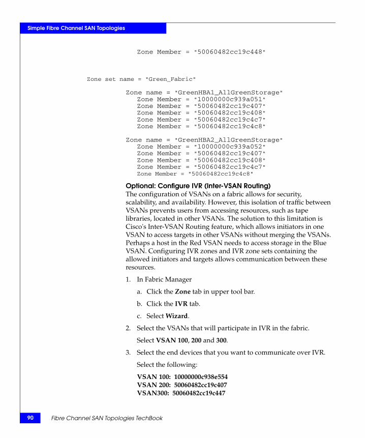
90
Simple Fibre Channel SAN Topologies
Zone Member = "50060482cc19c448"
Zone set name = "Green_Fabric"
Zone name = "GreenHBA1_AllGreenStorage"Zone Member = "10000000c939a051"Zone Member = "50060482cc19c407"Zone Member = "50060482cc19c408"Zone Member = "50060482cc19c4c7"Zone Member = "50060482cc19c4c8"
Zone name = "GreenHBA2_AllGreenStorage"Zone Member = "10000000c939a052"Zone Member = "50060482cc19c407"Zone Member = "50060482cc19c408"Zone Member = "50060482cc19c4c7"Zone Member = "50060482cc19c4c8"
Optional: Configure IVR (Inter-VSAN Routing) The configuration of VSANs on a fabric allows for security, scalability, and availability. However, this isolation of traffic between VSANs prevents users from accessing resources, such as tape libraries, located in other VSANs. The solution to this limitation is Cisco's Inter-VSAN Routing feature, which allows initiators in one VSAN to access targets in other VSANs without merging the VSANs. Perhaps a host in the Red VSAN needs to access storage in the Blue VSAN. Configuring IVR zones and IVR zone sets containing the allowed initiators and targets allows communication between these resources.
1. In Fabric Manager
a. Click the Zone tab in upper tool bar.
b. Click the IVR tab.
c. Select Wizard.
2. Select the VSANs that will participate in IVR in the fabric.
Select VSAN 100, 200 and 300.
3. Select the end devices that you want to communicate over IVR.
Select the following:
VSAN 100: 10000000c938e554VSAN 200: 50060482cc19c407VSAN300: 50060482cc19c447
Fibre Channel SAN Topologies TechBook
Simple Fibre Channel SAN Topologies
VSAN 300: 210100e08b8ac76d
4. Enter the VSAN ID of the VSAN you want to use as the transit VSAN between the VSANs selected for the IVR zone.
Select VSAN 1 as the transit VSAN.
Note: VSAN 1 connects both switches and all trunking traffic will pass over this link to communicate with VSANs in other switches.
5. Set the IVR zone and IVR zone set.
IVR NAME = IVRZONE1
IVR ZONENET NAME = IVRZONESET1
6. Verify all steps that Fabric Manager will take to configure IVR in the fabric.
7. Click Finish if you want to enable IVR NAT and IVR topology and to create the associated IVR zones and IVR zone set.
or
Click Cancel to exit the IVR Wizard without saving any changes.
8. The Save Configuration dialog box displays. You can save the configuration of the master to be copied to other IVR-enabled switches. Click either Continue Activation or Cancel.
9. Click Finish.
Complete the SAN setupAt this point the SAN is ready to pass I/O from host to storage. Other steps, such as configuring LUN masking and modification of host configuration files, are required before the SAN setup is complete. Refer to the Cisco MDS 9000 Family Fabric Manager Configuration Guide for more details.
Connectrix M example
General layout Figure 10 on page 92 shows an example of two ED-10000Ms (Brocade M series Intrepid 10000) using virtual switches.
Two switch fabrics 91
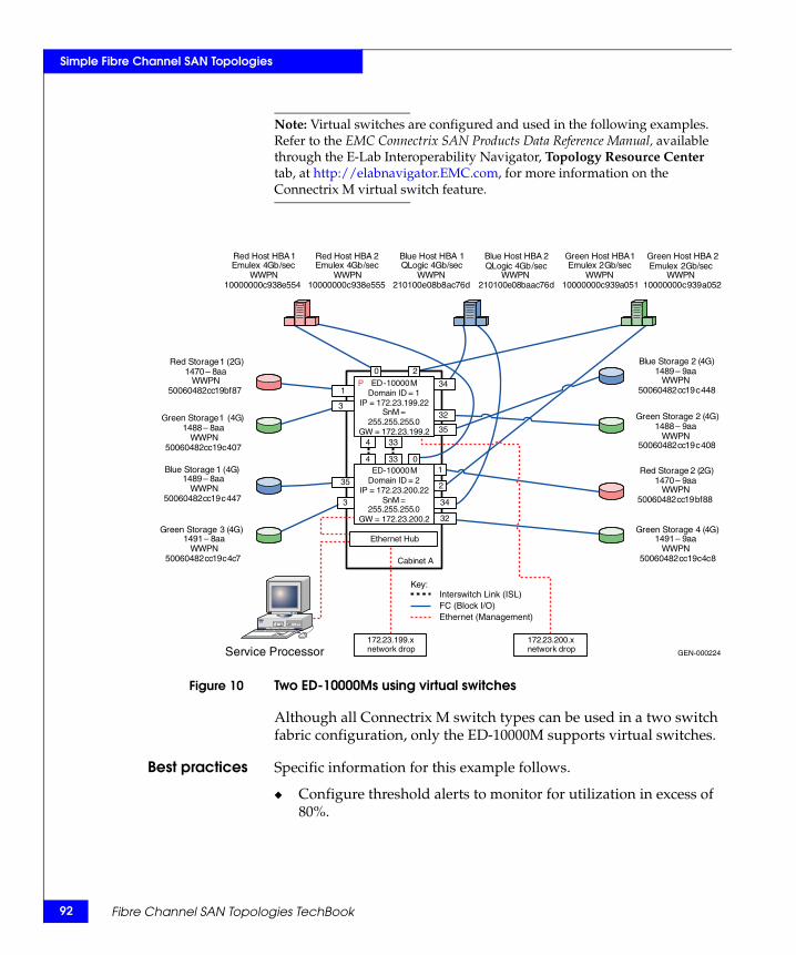
92
Simple Fibre Channel SAN Topologies
Note: Virtual switches are configured and used in the following examples. Refer to the EMC Connectrix SAN Products Data Reference Manual, available through the E-Lab Interoperability Navigator, Topology Resource Center tab, at http://elabnavigator.EMC.com, for more information on the Connectrix M virtual switch feature.
Figure 10 Two ED-10000Ms using virtual switches
Although all Connectrix M switch types can be used in a two switch fabric configuration, only the ED-10000M supports virtual switches.
Best practices Specific information for this example follows.
◆ Configure threshold alerts to monitor for utilization in excess of 80%.
GEN-000224
Key:
ED-10000MDomain ID = 2
IP = 172 . 23 . 200.22SnM =
255 . 255 . 255 . 0 GW = 172 . 23 . 200. 2
172 . 23 . 199 . x network drop
Cabinet A
Service Processor
Ethernet Hub
172 . 23 . 200 . x network drop
Red Host HBA 1 Emulex 4 Gb / sec
WWPN 10000000 c 938 e 554
Red Host HBA 2 Emulex 4 Gb / sec
WWPN 10000000 c 938 e 555
Green Host HBA 1 Emulex 2 Gb / sec
WWPN 10000000 c 939 a 051
Green Host HBA 2 Emulex 2 Gb / sec
WWPN 10000000 c 939 a 052
Blue Host HBA 1QLogic 4 Gb / sec
WWPN 210100 e 08 b 8 ac 76 d
Blue Host HBA 2 QLogic 4 Gb / sec
WWPN 210100 e 08 baac 76 d
Red Storage 2 (2G)1470 – 9aa
WWPN50060482cc19bf88
Red Storage 1 (2G)1470 – 8 aa
WWPN 50060482 cc 19 bf 87
Green Storage 1 ( 4 G ) 1488 – 8 aa
WWPN 50060482 cc 19 c 407
Green Storage 2 (4G)1488 – 9aa
WWPN50060482cc19c408
Blue Storage 1 ( 4 G ) 1489 – 8 aa
WWPN 50060482 cc 19 c 447
Blue Storage 2 (4G)1489 – 9aa
WWPN50060482cc19c448
Green Storage 3 ( 4 G ) 1491 – 8 aa
WWPN 50060482 cc 19 c 4 c 7
Green Storage 4 (4G)1491 – 9aa
WWPN50060482cc19c4c8
0
34
2
4 33 0
4 33
34
32
2
1
32
35
1
3
35
3
Interswitch Link (ISL) FC (Block I/O) Ethernet (Management)
ED-10000MDomain ID = 1
IP = 172 . 23 . 199 . 22 SnM =
255 . 255 . 255 . 0 GW = 172 . 23 . 199 . 2
P
Fibre Channel SAN Topologies TechBook
Simple Fibre Channel SAN Topologies
◆ Configure counter threshold alerts to monitor for invalid transmission words, encoding errors, and CRC errors. Any of these can indicate a problem with the physical link that may eventually lead to bleeding BB_Credit. If any ISLs will be used for long distance, monitoring for errors is a necessity.
◆ Configure a fencing policy.
For general information on best practices for two switch fabrics, refer to “Best practices” on page 69.
Host and storagelayout
ED-10000Ms are used in this configuration. Due to the small number of host and storage pairs as well as ISLs in this configuration, special considerations need not be made to ensure fairness. However, when a larger number of ports are present, host and storage layout can become important. Refer to ED-10000M fairness considerations in the EMC Connectrix SAN Products Data Reference Manual, available through the E-Lab Interoperability Navigator, Topology Resource Center tab, at http://elabnavigator.EMC.com.
For general information on host and storage layout for two switch fabrics, refer to “Host and storage layout” on page 70.
Switch and fabricmanagement
Connectrix Manager is used to configure this environment.
For general information on switch and fabric management for two switch fabrics, refer to “Switch and fabric management” on page 70.
Security In “Configure security” on page 106 default passwords are changed, Enterprise Fabric mode is enabled, and a Port Binding configuration will be put into effect.
For general information on security for two switch fabrics, refer to “Security” on page 70. For further information on security, refer to the Building Secure SANs TechBook, available through the E-Lab Interoperability Navigator, Topology Resource Center tab, at http://elabnavigator.EMC.com.
Setting up thistopology
Assumptions specific to this case study:
◆ The switches are installed in an EMC-supplied cabinet.
• For installation instructions, see Connectrix EC-1500 Cabinet Installation and Setup Manual, which can be accessed from Powerlink.
◆ The proper power receptacles have been provided by the customer.
Two switch fabrics 93
94
Simple Fibre Channel SAN Topologies
• For switch power requirements, refer to the EMC Connectrix SAN Products Data Reference Manual, available through the E-Lab Interoperability Navigator, Topology Resource Center tab, at http://elabnavigator.EMC.com.
• For Cabinet power requirements, refer to Connectrix EC-1500 Cabinet Installation and Setup Manual, which can be accessed from Powerlink.
◆ The switches have not been connected to the power source and are not powered on.
◆ Network drops, IP addresses, subnet mask, and gateway have been provided by the customer.
◆ For switch or cabinet network requirements, refer to refer to the EMC Connectrix SAN Products Data Reference Manual, available through the E-Lab Interoperability Navigator, Topology Resource Center tab, at http://elabnavigator.EMC.com.
Note: Connectrix M switches can be either attached to the Ethernet hub that comes with the cabinet, or directly connected to the customer’s LAN. In both cases, the switches can be placed on either a public or private network. There are advantages to both configurations. For more information, refer to "Public versus private" in the Networked Storage Concepts and Protocols TechBook, available through the E-Lab Interoperability Navigator, Topology Resource Center tab, at http://elabnavigator.EMC.com.
This example assumes that the customer has provided us with two Ethernet cables and that one of them is on the 172.23.199.x network and that the other is connected to the 172.23.200.x network.
◆ The correct number of LMQs have been installed in each chassis. In this case, two LMQs in each chassis are required.
• For help in determining how many ports are required, refer to "Determining customer requirements" in the Networked Storage Concepts and Protocols TechBook, available through the E-Lab Interoperability Navigator, Topology Resource Center tab, at http://elabnavigator.EMC.com.
◆ License keys have been obtained.
• Go to the URL listed on the transaction code certificate that shipped with the product to get the license key.
◆ A Service Processor is installed in at least one of the cabinets.
Fibre Channel SAN Topologies TechBook
Simple Fibre Channel SAN Topologies
◆ A laptop supplied by the installer will be used to configure the IP addressees of the switches. This laptop has a serial DB-9 connector.
◆ A null modem cable is available.
◆ The customer has provided a temporary password that will be used as the default password when configuring the IP address.
◆ Use Connectrix Manager. The Connectrix Manager installation kit is available.
◆ Connectrix Manager is not already installed on the Service Processor.
Configure the IP address
To configure the IP address:
1. Power up the cabinet by connecting the power cords to the power receptacles provided by the customer. This causes both the directors and the Service Processor to power up.
2. Select one of the switches to configure.
Note: This example will start with the switch with a Domain ID of 1 and an IP address of 172.23.199.22.
Change a product IP address, subnet mask, or gateway address
Perform the following steps to change a product IP address, subnet mask, or gateway address. An asynchronous RS-232 modem cable and maintenance terminal (desktop or notebook PC) with a Windows-based operating system and RS-232 serial communication software (such as ProComm Plus or HyperTerminal) are required.
1. Connect one end of the RS-232 modem cable to the 9-pin maintenance port on the active CTP card. The active CTP card is identified by the green Role LED.
2. Connect the other cable end to a 9-pin serial communication port (COM1 or COM2) at the rear of the maintenance terminal PC.
3. Power on the maintenance terminal. At the Windows desktop, click Start at the left side of the task bar. The Windows Workstation menu appears.
Two switch fabrics 95
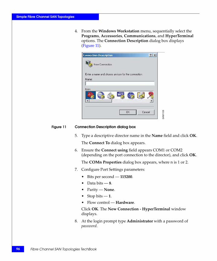
96
Simple Fibre Channel SAN Topologies
4. From the Windows Workstation menu, sequentially select the Programs, Accessories, Communications, and HyperTerminal options. The Connection Description dialog box displays (Figure 11).
Figure 11 Connection Description dialog box
5. Type a descriptive director name in the Name field and click OK.
The Connect To dialog box appears.
6. Ensure the Connect using field appears COM1 or COM2 (depending on the port connection to the director), and click OK.
The COMn Properties dialog box appears, where n is 1 or 2.
7. Configure Port Settings parameters:
• Bits per second — 115200.
• Data bits — 8.
• Parity — None.
• Stop bits — 1.
• Flow control — Hardware.
Click OK. The New Connection - HyperTerminal window displays.
8. At the login prompt type Administrator with a password of password.
Fibre Channel SAN Topologies TechBook
Simple Fibre Channel SAN Topologies
9. At the EOS# prompt, type the system ip command and press Enter. The New Connection - HyperTerminal window appears with configuration information listed:
• IP address (default is 10.1.1.10).
Note: IP address is the preinstalled IP address but may not be correct for the director.
• Subnet mask (default is 250.0.0.0)
• Gateway address (default is 0.0.0.0)
10. Change the IP address, subnet mask, and gateway address as directed by the customer. To change the addresses, type the following and press Enter.
system ip 172.23.199.22 255.255.255.0 172.23.199.2
The IP address is xxx.xxx.xxx.xxx, the subnet mask is yyy.yyy.yyy.yyy, and the gateway address is zzz.zzz.zzz.zzz, where the octets xxx, yyy, and zzz are decimals from zero through 255. If an address is to remain unchanged, type the current address in the respective field.
To configure the switch IP address of the other switch in the cabinet, follow Step 3 through Step 10, above and use the IP address of 172.23.200.22.
Install Connectrix Manager
Note: Refer to the EMC Connectrix Manager User Guide for complete installation instructions.
To install Connectrix Manager:
1. Insert the Connectrix Manager installation CD into the CD-RW drive.
2. Browse to the CD-RW drive in windows explorer.
3. Locate, then double-click, the install.exe file. The installer is displayed. Typically, this file is located under the CtxMgr <version number> folder.
4. Accept all the defaults by clicking Next and OK, when appropriate.
5. Click Done when the Installation Complete dialog box appears.
Two switch fabrics 97
98
Simple Fibre Channel SAN Topologies
6. Click Next when the Welcome dialog box appears.
7. Accept the EULA terms and click Next.
8. At the Copy data and Settings dialog box, select No, then Next.
Note: "No" is selected in this step since this section assumes this is a new installation.
9. Assign a Connectrix Manager 9.0 server name, and then click Next.
This case uses CMServer.
10. Enter the serial number and license key in the provided fields in the Connectrix Manager 9.0 Server License dialog box.
• The serial number is located on the back of the Connectrix Manager installation CD case.
• To obtain a license key, locate the transaction code certificate and go to the URL listed.
a. Enter the serial number located on the back of the Connectrix Manager installation CD case.
b. In the Transaction Code fields, type the transaction code(s) shipped with the software.
c. Click Next.
d. Confirm the existing and new features to be enabled.
e. Click Next.
The license key and all enabled features appears.
f. Retain a copy for your records.
g. Enter this key into the License key field.
h. Click OK.
11. Once the installation is complete, log in to Connectrix Manager with the username of administrator and the password of password.
Note: Change this default as soon as possible. For this example, the username nnn and password nnn are used.
Fibre Channel SAN Topologies TechBook
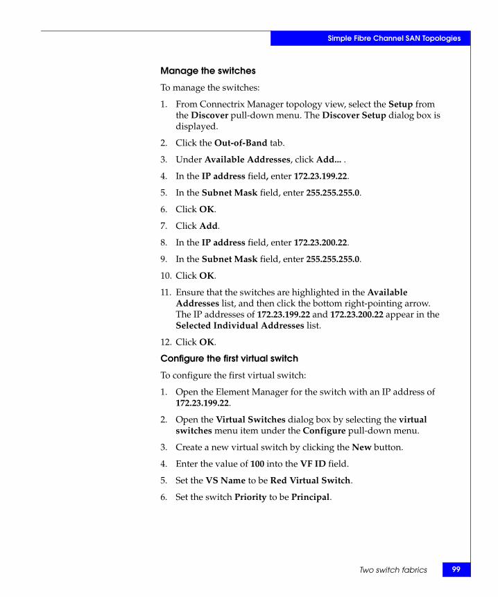
Simple Fibre Channel SAN Topologies
Manage the switches
To manage the switches:
1. From Connectrix Manager topology view, select the Setup from the Discover pull-down menu. The Discover Setup dialog box is displayed.
2. Click the Out-of-Band tab.
3. Under Available Addresses, click Add... .
4. In the IP address field, enter 172.23.199.22.
5. In the Subnet Mask field, enter 255.255.255.0.
6. Click OK.
7. Click Add.
8. In the IP address field, enter 172.23.200.22.
9. In the Subnet Mask field, enter 255.255.255.0.
10. Click OK.
11. Ensure that the switches are highlighted in the Available Addresses list, and then click the bottom right-pointing arrow. The IP addresses of 172.23.199.22 and 172.23.200.22 appear in the Selected Individual Addresses list.
12. Click OK.
Configure the first virtual switch
To configure the first virtual switch:
1. Open the Element Manager for the switch with an IP address of 172.23.199.22.
2. Open the Virtual Switches dialog box by selecting the virtual switches menu item under the Configure pull-down menu.
3. Create a new virtual switch by clicking the New button.
4. Enter the value of 100 into the VF ID field.
5. Set the VS Name to be Red Virtual Switch.
6. Set the switch Priority to be Principal.
Two switch fabrics 99
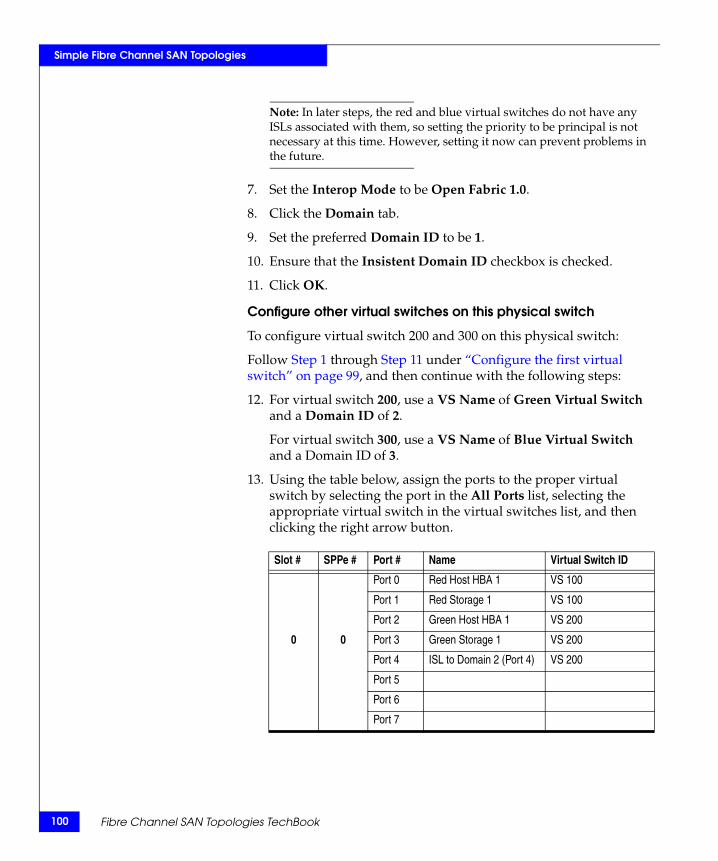
100
Simple Fibre Channel SAN Topologies
Note: In later steps, the red and blue virtual switches do not have any ISLs associated with them, so setting the priority to be principal is not necessary at this time. However, setting it now can prevent problems in the future.
7. Set the Interop Mode to be Open Fabric 1.0.
8. Click the Domain tab.
9. Set the preferred Domain ID to be 1.
10. Ensure that the Insistent Domain ID checkbox is checked.
11. Click OK.
Configure other virtual switches on this physical switch
To configure virtual switch 200 and 300 on this physical switch:
Follow Step 1 through Step 11 under “Configure the first virtual switch” on page 99, and then continue with the following steps:
12. For virtual switch 200, use a VS Name of Green Virtual Switch and a Domain ID of 2.
For virtual switch 300, use a VS Name of Blue Virtual Switch and a Domain ID of 3.
13. Using the table below, assign the ports to the proper virtual switch by selecting the port in the All Ports list, selecting the appropriate virtual switch in the virtual switches list, and then clicking the right arrow button.
Slot # SPPe # Port # Name Virtual Switch ID
Port 0 Red Host HBA 1 VS 100
Port 1 Red Storage 1 VS 100
Port 2 Green Host HBA 1 VS 200
0 0 Port 3 Green Storage 1 VS 200
Port 4 ISL to Domain 2 (Port 4) VS 200
Port 5
Port 6
Port 7
Fibre Channel SAN Topologies TechBook

Simple Fibre Channel SAN Topologies
14. Click OK.
Configure virtual switches on the physical switch with an IP address of 172.23.200.22
To configure virtual switches 100, 200, and 300:
Follow Step 1 through Step 11 under “Configure the first virtual switch” on page 99, and then continue with the following steps:
12. For virtual switch 100, use a VS Name of Red Virtual Switch and a Domain ID of 11 and leave switch priority at default.
For virtual switch 200, use a VS Name of Green Virtual Switch and a Domain ID of 12and leave switch priority at default.
For virtual switch 300, use a VS Name of Blue Virtual Switch and a Domain ID of 13 and leave switch priority at default.
13. Using the table below, assign the ports to the proper virtual switch by selecting the port in the All Ports list, selecting the appropriate virtual switch in the virtual switches list, and then clicking the right arrow button.
1 0
Port 32 Green Storage 2 VS 200
Port 33 ISL to Domain 2 (Port 33) VS 200
Port 34 Blue Host HBA 1 VS 300
Port 35 Blue Storage 1 VS 300
Port 36
Port 37
Port 38
Port 39
Slot # SPPe # Port # Name Virtual Switch ID
Port 0 Red Host HBA 2 VS 100
Port 1 Red Storage 2 VS 100
Port 2 Green Host HBA 2 VS 200
0 0 Port 3 Green Storage 3 VS 200
Port 4 ISL to Domain 1 (Port 4) VS 200
Port 5
Port 6
Port 7
Slot # SPPe # Port # Name Virtual Switch ID
Two switch fabrics 101
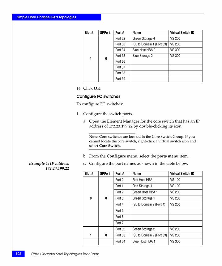
102
Simple Fibre Channel SAN Topologies
14. Click OK.
Configure FC switches
To configure FC switches:
1. Configure the switch ports.
a. Open the Element Manager for the core switch that has an IP address of 172.23.199.22 by double-clicking its icon.
Note: Core switches are located in the Core Switch Group. If you cannot locate the core switch, right-click a virtual switch icon and select Core Switch.
b. From the Configure menu, select the ports menu item.
Example 1: IP address172.23.199.22
c. Configure the port names as shown in the table below.
1 0
Port 32 Green Storage 4 VS 200
Port 33 ISL to Domain 1 (Port 33) VS 200
Port 34 Blue Host HBA 2 VS 300
Port 35 Blue Storage 2 VS 300
Port 36
Port 37
Port 38
Port 39
Slot # SPPe # Port # Name Virtual Switch ID
Slot # SPPe # Port # Name Virtual Switch ID
Port 0 Red Host HBA 1 VS 100
Port 1 Red Storage 1 VS 100
Port 2 Green Host HBA 1 VS 200
0 0 Port 3 Green Storage 1 VS 200
Port 4 ISL to Domain 2 (Port 4) VS 200
Port 5
Port 6
Port 7
Port 32 Green Storage 2 VS 200
1 0 Port 33 ISL to Domain 2 (Port 33) VS 200
Port 34 Blue Host HBA 1 VS 300
Fibre Channel SAN Topologies TechBook
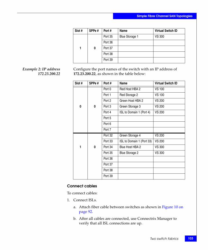
Simple Fibre Channel SAN Topologies
Example 2: IP address172.23.200.22
Configure the port names of the switch with an IP address of 172.23.200.22, as shown in the table below:
Connect cables
To connect cables:
1. Connect ISLs.
a. Attach fiber cable between switches as shown in Figure 10 on page 92.
b. After all cables are connected, use Connectrix Manager to verify that all ISL connections are up.
1 0
Port 35 Blue Storage 1 VS 300
Port 36
Port 37
Port 38
Port 39
Slot # SPPe # Port # Name Virtual Switch ID
Slot # SPPe # Port # Name Virtual Switch ID
Port 0 Red Host HBA 2 VS 100
Port 1 Red Storage 2 VS 100
Port 2 Green Host HBA 2 VS 200
0 0 Port 3 Green Storage 3 VS 200
Port 4 ISL to Domain 1 (Port 4) VS 200
Port 5
Port 6
Port 7
Port 32 Green Storage 4 VS 200
Port 33 ISL to Domain 1 (Port 33) VS 200
1 0 Port 34 Blue Host HBA 2 VS 300
Port 35 Blue Storage 2 VS 300
Port 36
Port 37
Port 38
Port 39
Two switch fabrics 103
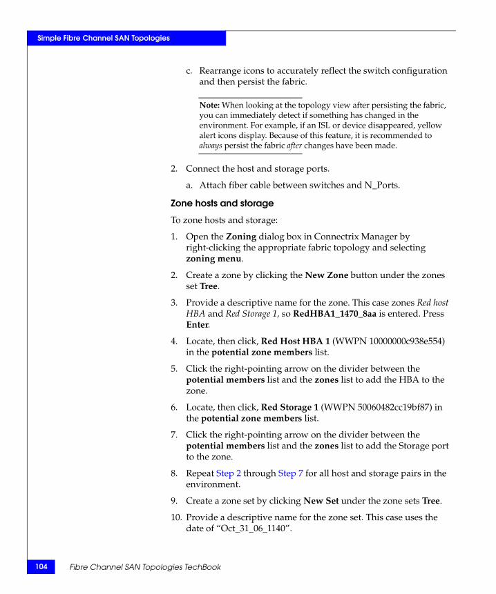
104
Simple Fibre Channel SAN Topologies
c. Rearrange icons to accurately reflect the switch configuration and then persist the fabric.
Note: When looking at the topology view after persisting the fabric, you can immediately detect if something has changed in the environment. For example, if an ISL or device disappeared, yellow alert icons display. Because of this feature, it is recommended to always persist the fabric after changes have been made.
2. Connect the host and storage ports.
a. Attach fiber cable between switches and N_Ports.
Zone hosts and storage
To zone hosts and storage:
1. Open the Zoning dialog box in Connectrix Manager by right-clicking the appropriate fabric topology and selecting zoning menu.
2. Create a zone by clicking the New Zone button under the zones set Tree.
3. Provide a descriptive name for the zone. This case zones Red host HBA and Red Storage 1, so RedHBA1_1470_8aa is entered. Press Enter.
4. Locate, then click, Red Host HBA 1 (WWPN 10000000c938e554) in the potential zone members list.
5. Click the right-pointing arrow on the divider between the potential members list and the zones list to add the HBA to the zone.
6. Locate, then click, Red Storage 1 (WWPN 50060482cc19bf87) in the potential zone members list.
7. Click the right-pointing arrow on the divider between the potential members list and the zones list to add the Storage port to the zone.
8. Repeat Step 2 through Step 7 for all host and storage pairs in the environment.
9. Create a zone set by clicking New Set under the zone sets Tree.
10. Provide a descriptive name for the zone set. This case uses the date of “Oct_31_06_1140”.
Fibre Channel SAN Topologies TechBook
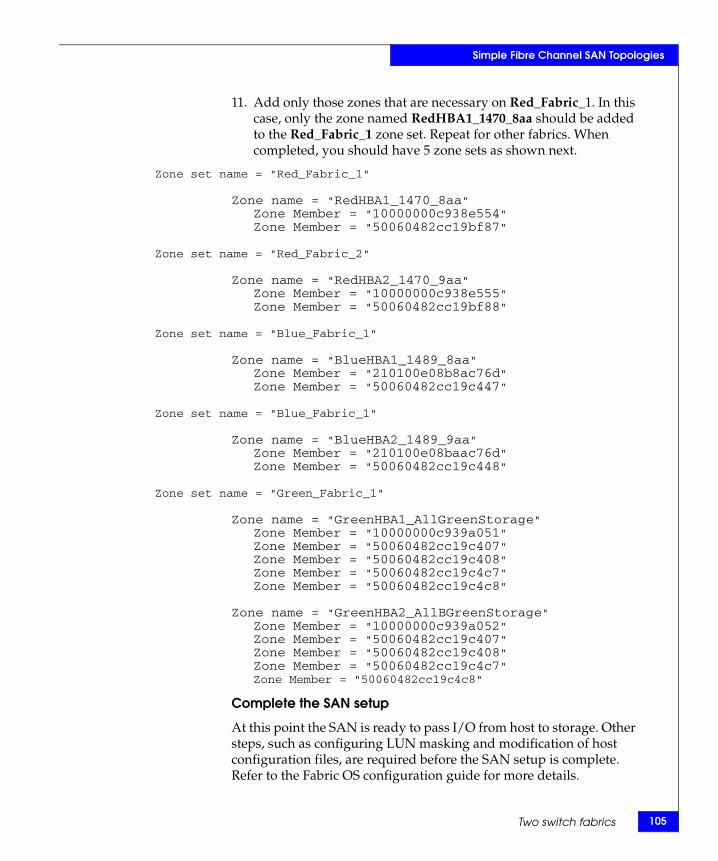
Simple Fibre Channel SAN Topologies
11. Add only those zones that are necessary on Red_Fabric_1. In this case, only the zone named RedHBA1_1470_8aa should be added to the Red_Fabric_1 zone set. Repeat for other fabrics. When completed, you should have 5 zone sets as shown next.
Zone set name = "Red_Fabric_1"
Zone name = "RedHBA1_1470_8aa"Zone Member = "10000000c938e554"Zone Member = "50060482cc19bf87"
Zone set name = "Red_Fabric_2"
Zone name = "RedHBA2_1470_9aa"Zone Member = "10000000c938e555"Zone Member = "50060482cc19bf88"
Zone set name = "Blue_Fabric_1"
Zone name = "BlueHBA1_1489_8aa"Zone Member = "210100e08b8ac76d"Zone Member = "50060482cc19c447"
Zone set name = "Blue_Fabric_1"
Zone name = "BlueHBA2_1489_9aa"Zone Member = "210100e08baac76d"Zone Member = "50060482cc19c448"
Zone set name = "Green_Fabric_1"
Zone name = "GreenHBA1_AllGreenStorage"Zone Member = "10000000c939a051"Zone Member = "50060482cc19c407"Zone Member = "50060482cc19c408"Zone Member = "50060482cc19c4c7"Zone Member = "50060482cc19c4c8"
Zone name = "GreenHBA2_AllBGreenStorage"Zone Member = "10000000c939a052"Zone Member = "50060482cc19c407"Zone Member = "50060482cc19c408"Zone Member = "50060482cc19c4c7"Zone Member = "50060482cc19c4c8"
Complete the SAN setup
At this point the SAN is ready to pass I/O from host to storage. Other steps, such as configuring LUN masking and modification of host configuration files, are required before the SAN setup is complete. Refer to the Fabric OS configuration guide for more details.
Two switch fabrics 105
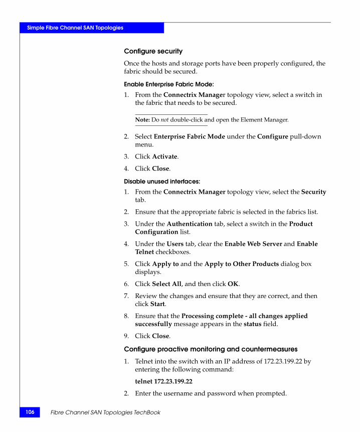
106
Simple Fibre Channel SAN Topologies
Configure security
Once the hosts and storage ports have been properly configured, the fabric should be secured.
Enable Enterprise Fabric Mode:
1. From the Connectrix Manager topology view, select a switch in the fabric that needs to be secured.
Note: Do not double-click and open the Element Manager.
2. Select Enterprise Fabric Mode under the Configure pull-down menu.
3. Click Activate.
4. Click Close.
Disable unused interfaces:
1. From the Connectrix Manager topology view, select the Security tab.
2. Ensure that the appropriate fabric is selected in the fabrics list.
3. Under the Authentication tab, select a switch in the Product Configuration list.
4. Under the Users tab, clear the Enable Web Server and Enable Telnet checkboxes.
5. Click Apply to and the Apply to Other Products dialog box displays.
6. Click Select All, and then click OK.
7. Review the changes and ensure that they are correct, and then click Start.
8. Ensure that the Processing complete - all changes applied successfully message appears in the status field.
9. Click Close.
Configure proactive monitoring and countermeasures
1. Telnet into the switch with an IP address of 172.23.199.22 by entering the following command:
telnet 172.23.199.22
2. Enter the username and password when prompted.
Fibre Channel SAN Topologies TechBook
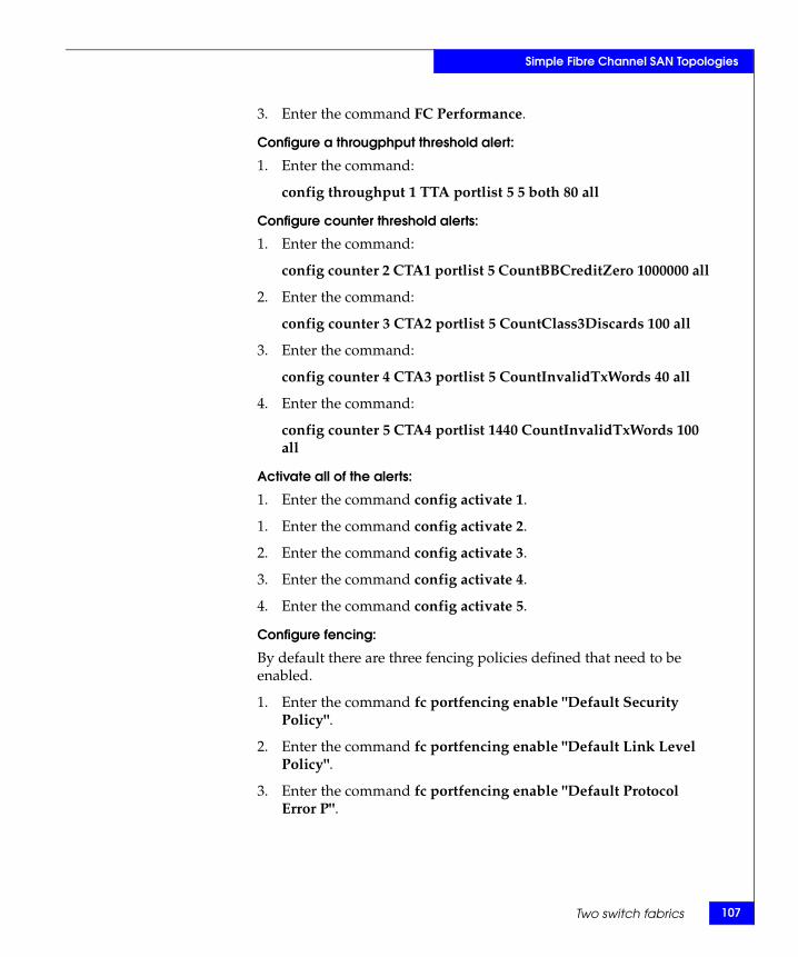
Simple Fibre Channel SAN Topologies
3. Enter the command FC Performance.
Configure a througphput threshold alert:
1. Enter the command:
config throughput 1 TTA portlist 5 5 both 80 all
Configure counter threshold alerts:
1. Enter the command:
config counter 2 CTA1 portlist 5 CountBBCreditZero 1000000 all
2. Enter the command:
config counter 3 CTA2 portlist 5 CountClass3Discards 100 all
3. Enter the command:
config counter 4 CTA3 portlist 5 CountInvalidTxWords 40 all
4. Enter the command:
config counter 5 CTA4 portlist 1440 CountInvalidTxWords 100 all
Activate all of the alerts:
1. Enter the command config activate 1.
1. Enter the command config activate 2.
2. Enter the command config activate 3.
3. Enter the command config activate 4.
4. Enter the command config activate 5.
Configure fencing:
By default there are three fencing policies defined that need to be enabled.
1. Enter the command fc portfencing enable "Default Security Policy".
2. Enter the command fc portfencing enable "Default Link Level Policy".
3. Enter the command fc portfencing enable "Default Protocol Error P".
Two switch fabrics 107
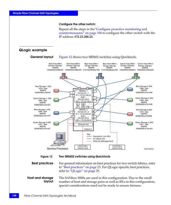
108
Simple Fibre Channel SAN Topologies
Configure the other switch:
Repeat all the steps in the“Configure proactive monitoring and countermeasures” on page 106 to configure the other switch with the IP address 172.23.200.22.
QLogic example
General layout Figure 12 shows two SB5602 switches using Quicktools.
Figure 12 Two SB5602 switches using Quicktools
Best practices For general information on best practices for two switch fabrics, refer to “Best practices” on page 23. For QLogic-specific best practices, refer to “QLogic” on page 29.
Host and storagelayout
The SANbox 9000s are used in this configuration. Due to the small number of host and storage pairs as well as ISLs in this configuration, special considerations need not be made to ensure fairness.
GEN-000234
Key:
SB5602_2Domain ID = 2
IP = 172 . 23 . 200.22SnM =
255 . 255 . 255 . 0 GW = 172 . 23 . 200. 2
172 . 23 . 199 . x network drop
Cabinet A
Service Processor
Ethernet Hub
172 . 23 . 200 . x network drop
Red Host HBA 1 Emulex 4 Gb / sec
WWPN 10000000 c 938 e 554
Red Host HBA 2 Emulex 4 Gb / sec
WWPN 10000000 c 938 e 555
Green Host HBA 1 Emulex 2 Gb / sec
WWPN 10000000 c 939 a 051
Green Host HBA 2 Emulex 2 Gb / sec
WWPN 10000000 c 939 a 052
Blue Host HBA 1QLogic 4 Gb / sec
WWPN 210100 e 08 b 8 ac 76 d
Blue Host HBA 2 QLogic 4 Gb / sec
WWPN 210100 e 08 baac 76 d
Red Storage 2 (2G)1470 – 9aa
WWPN50060482cc19bf88
Red Storage 1 (2G)1470 – 8 aa
WWPN 50060482 cc 19 bf 87
Green Storage 1 (4G)1488 – 8 aa
WWPN 50060482 cc 19 c 407
Green Storage 2 (4G)1488 – 9aa
WWPN50060482cc19c408
Blue Storage 1 ( 4 G ) 1489 – 8 aa
WWPN 50060482 cc 19 c 447
Blue Storage 2 (4G)1489 – 9aa
WWPN50060482cc19c448
Green Storage 3 ( 4 G ) 1491 – 8 aa
WWPN 50060482 cc 19 c 4 c 7
Green Storage 4 (4G)1491 – 9aa
WWPN50060482cc19c4c8
0
8
2
4 33 0
4 33
8
7
2
1
7
6
1
3
6
3
Interswitch Link (ISL) FC (Block I/O) Ethernet (Management)
SB5602_1Domain ID = 1
IP = 172 . 23 . 199 . 22 SnM =
255 . 255 . 255 . 0 GW = 172 . 23 . 199 . 2
P
Fibre Channel SAN Topologies TechBook
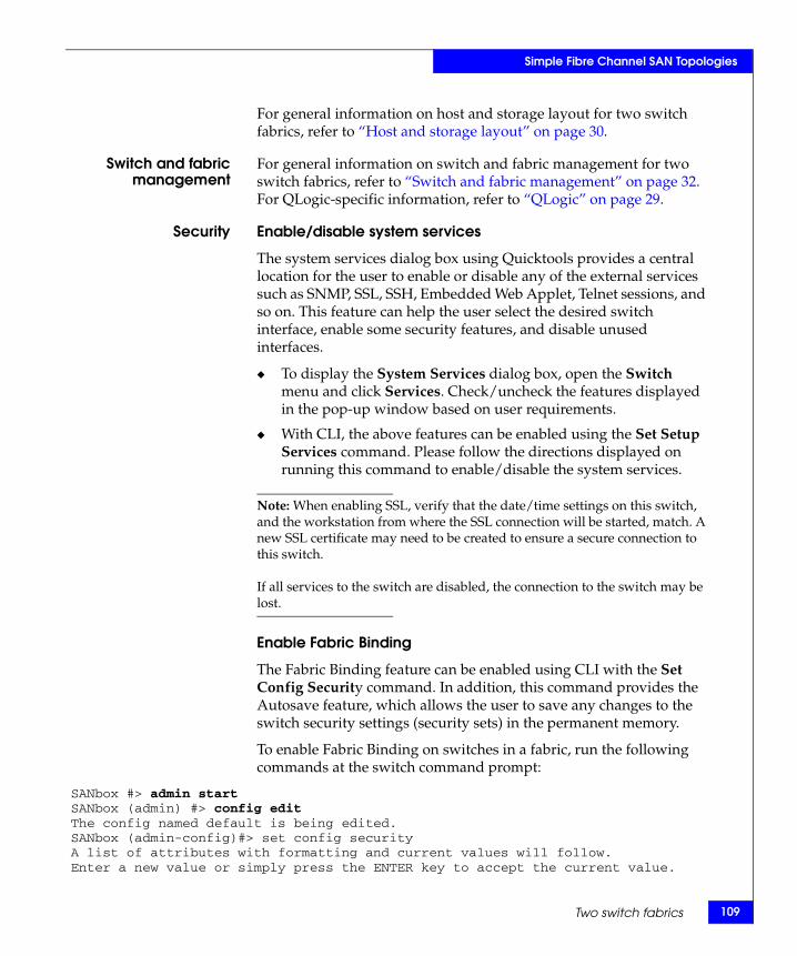
Simple Fibre Channel SAN Topologies
For general information on host and storage layout for two switch fabrics, refer to “Host and storage layout” on page 30.
Switch and fabricmanagement
For general information on switch and fabric management for two switch fabrics, refer to “Switch and fabric management” on page 32. For QLogic-specific information, refer to “QLogic” on page 29.
Security Enable/disable system services
The system services dialog box using Quicktools provides a central location for the user to enable or disable any of the external services such as SNMP, SSL, SSH, Embedded Web Applet, Telnet sessions, and so on. This feature can help the user select the desired switch interface, enable some security features, and disable unused interfaces.
◆ To display the System Services dialog box, open the Switch menu and click Services. Check/uncheck the features displayed in the pop-up window based on user requirements.
◆ With CLI, the above features can be enabled using the Set Setup Services command. Please follow the directions displayed on running this command to enable/disable the system services.
Note: When enabling SSL, verify that the date/time settings on this switch, and the workstation from where the SSL connection will be started, match. A new SSL certificate may need to be created to ensure a secure connection to this switch.
If all services to the switch are disabled, the connection to the switch may be lost.
Enable Fabric Binding
The Fabric Binding feature can be enabled using CLI with the Set Config Security command. In addition, this command provides the Autosave feature, which allows the user to save any changes to the switch security settings (security sets) in the permanent memory.
To enable Fabric Binding on switches in a fabric, run the following commands at the switch command prompt:
SANbox #> admin startSANbox (admin) #> config editThe config named default is being edited.SANbox (admin-config)#> set config securityA list of attributes with formatting and current values will follow.Enter a new value or simply press the ENTER key to accept the current value.
Two switch fabrics 109
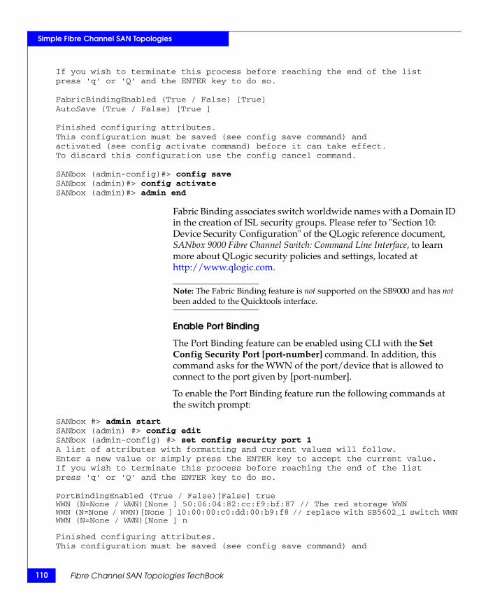
110
Simple Fibre Channel SAN Topologies
If you wish to terminate this process before reaching the end of the listpress 'q' or 'Q' and the ENTER key to do so.
FabricBindingEnabled (True / False) [True]AutoSave (True / False) [True ]
Finished configuring attributes.This configuration must be saved (see config save command) andactivated (see config activate command) before it can take effect.To discard this configuration use the config cancel command.
SANbox (admin-config)#> config saveSANbox (admin)#> config activateSANbox (admin)#> admin end
Fabric Binding associates switch worldwide names with a Domain ID in the creation of ISL security groups. Please refer to "Section 10: Device Security Configuration" of the QLogic reference document, SANbox 9000 Fibre Channel Switch: Command Line Interface, to learn more about QLogic security policies and settings, located at http://www.qlogic.com.
Note: The Fabric Binding feature is not supported on the SB9000 and has not been added to the Quicktools interface.
Enable Port Binding
The Port Binding feature can be enabled using CLI with the Set Config Security Port [port-number] command. In addition, this command asks for the WWN of the port/device that is allowed to connect to the port given by [port-number].
To enable the Port Binding feature run the following commands at the switch prompt:
SANbox #> admin startSANbox (admin) #> config editSANbox (admin-config) #> set config security port 1A list of attributes with formatting and current values will follow.Enter a new value or simply press the ENTER key to accept the current value.If you wish to terminate this process before reaching the end of the listpress 'q' or 'Q' and the ENTER key to do so.
PortBindingEnabled (True / False)[False] trueWWN (N=None / WWN)[None ] 50:06:04:82:cc:f9:bf:87 // The red storage WWNWWN (N=None / WWN)[None ] 10:00:00:c0:dd:00:b9:f8 // replace with SB5602_1 switch WWNWWN (N=None / WWN)[None ] n
Finished configuring attributes.This configuration must be saved (see config save command) and
Fibre Channel SAN Topologies TechBook
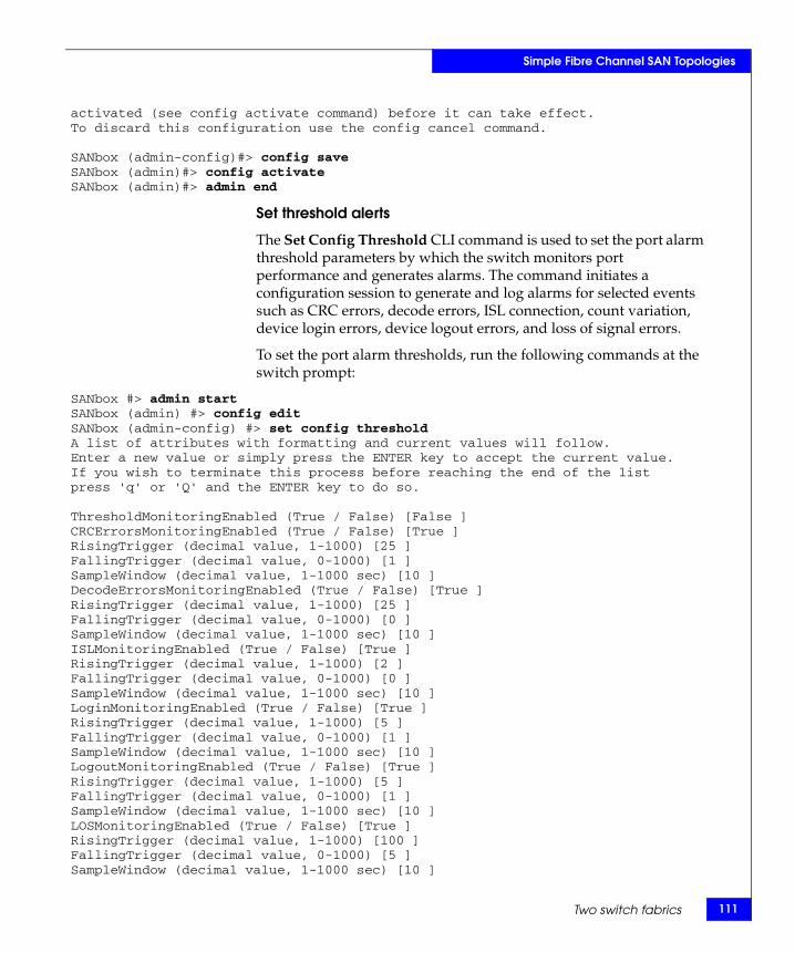
Simple Fibre Channel SAN Topologies
activated (see config activate command) before it can take effect.To discard this configuration use the config cancel command.
SANbox (admin-config)#> config saveSANbox (admin)#> config activateSANbox (admin)#> admin end
Set threshold alerts
The Set Config Threshold CLI command is used to set the port alarm threshold parameters by which the switch monitors port performance and generates alarms. The command initiates a configuration session to generate and log alarms for selected events such as CRC errors, decode errors, ISL connection, count variation, device login errors, device logout errors, and loss of signal errors.
To set the port alarm thresholds, run the following commands at the switch prompt:
SANbox #> admin startSANbox (admin) #> config editSANbox (admin-config) #> set config thresholdA list of attributes with formatting and current values will follow.Enter a new value or simply press the ENTER key to accept the current value.If you wish to terminate this process before reaching the end of the listpress 'q' or 'Q' and the ENTER key to do so.
ThresholdMonitoringEnabled (True / False) [False ]CRCErrorsMonitoringEnabled (True / False) [True ]RisingTrigger (decimal value, 1-1000) [25 ]FallingTrigger (decimal value, 0-1000) [1 ]SampleWindow (decimal value, 1-1000 sec) [10 ]DecodeErrorsMonitoringEnabled (True / False) [True ]RisingTrigger (decimal value, 1-1000) [25 ]FallingTrigger (decimal value, 0-1000) [0 ]SampleWindow (decimal value, 1-1000 sec) [10 ]ISLMonitoringEnabled (True / False) [True ]RisingTrigger (decimal value, 1-1000) [2 ]FallingTrigger (decimal value, 0-1000) [0 ]SampleWindow (decimal value, 1-1000 sec) [10 ]LoginMonitoringEnabled (True / False) [True ]RisingTrigger (decimal value, 1-1000) [5 ]FallingTrigger (decimal value, 0-1000) [1 ]SampleWindow (decimal value, 1-1000 sec) [10 ]LogoutMonitoringEnabled (True / False) [True ]RisingTrigger (decimal value, 1-1000) [5 ]FallingTrigger (decimal value, 0-1000) [1 ]SampleWindow (decimal value, 1-1000 sec) [10 ]LOSMonitoringEnabled (True / False) [True ]RisingTrigger (decimal value, 1-1000) [100 ]FallingTrigger (decimal value, 0-1000) [5 ]SampleWindow (decimal value, 1-1000 sec) [10 ]
Two switch fabrics 111
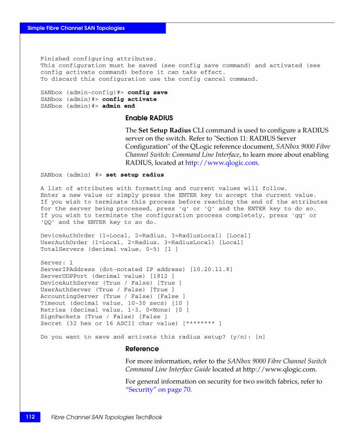
112
Simple Fibre Channel SAN Topologies
Finished configuring attributes.This configuration must be saved (see config save command) and activated (seeconfig activate command) before it can take effect.To discard this configuration use the config cancel command. SANbox (admin-config)#> config saveSANbox (admin)#> config activateSANbox (admin)#> admin end
Enable RADIUS
The Set Setup Radius CLI command is used to configure a RADIUS server on the switch. Refer to "Section 11: RADIUS Server Configuration" of the QLogic reference document, SANbox 9000 Fibre Channel Switch: Command Line Interface, to learn more about enabling RADIUS, located at http://www.qlogic.com.
SANbox (admin) #> set setup radius
A list of attributes with formatting and current values will follow.Enter a new value or simply press the ENTER key to accept the current value.If you wish to terminate this process before reaching the end of the attributesfor the server being processed, press 'q' or 'Q' and the ENTER key to do so.If you wish to terminate the configuration process completely, press 'qq' or'QQ' and the ENTER key to so do.
DeviceAuthOrder (1=Local, 2=Radius, 3=RadiusLocal) [Local]UserAuthOrder (1=Local, 2=Radius, 3=RadiusLocal) [Local]TotalServers (decimal value, 0-5) [1 ]
Server: 1ServerIPAddress (dot-notated IP address) [10.20.11.8]ServerUDPPort (decimal value) [1812 ]DeviceAuthServer (True / False) [True ]UserAuthServer (True / False) [True ]AccountingServer (True / False) [False ]Timeout (decimal value, 10-30 secs) [10 ]Retries (decimal value, 1-3, 0=None) [0 ]SignPackets (True / False) [False ]Secret (32 hex or 16 ASCII char value) [******** ]
Do you want to save and activate this radius setup? (y/n): [n]
Reference
For more information, refer to the SANbox 9000 Fibre Channel Switch Command Line Interface Guide located at http://www.qlogic.com.
For general information on security for two switch fabrics, refer to “Security” on page 70.
Fibre Channel SAN Topologies TechBook
Simple Fibre Channel SAN Topologies
Setting up thistopology
Assumptions specific to this case study:
◆ The QLogic SB5602 switches are installed in a customer-supplied cabinet.
For switch installation guidelines, refer to the Sections 3 and 4: Planning and Installation for an SB5602 switch located at http://www.qlogic.com.
◆ The customer has provided the proper power receptacles.
The power requirements for the SB5602 are 1 Amp at 100VAC or 0.5 Amp at 240VAC. For cabinet power requirements, refer to the customer-supplied cabinet Setup Manual, if any.
◆ The switches have not been connected to the power source and are not powered on.
◆ Network drops, IP addresses, subnet mask, gateway, and other pertinent information have been provided by the customer.
For switch network requirements refer to Section 2: General Description and Section 4: Installation for an SB5602 switch located at http://www.qlogic.com.
The switches can be placed on either a public or private network. There are advantages to both configurations. For more information, refer to "Public versus private" in the Networked Storage Concepts and Protocols TechBook, available through the E-Lab Interoperability Navigator, Topology Resource Center tab, at http://elabnavigator.EMC.com.
In this example, it is assumed that the customer has provided two Ethernet cables and that one of them is on the 172.23.199.x network and that the other is connected to the 172.23.200.x network.
◆ License keys have been obtained.
• To obtain a license key, go to the URL listed on the transaction code certificate that shipped with the product.
◆ A laptop, supplied by the installer, is used to configure the IP addresses of the switches. One interface from this laptop is directly connected to the FC switch through a crossover cable (one switch at a time), and this interface has an IP address of 10.0.0.253.
◆ A null modem cable is available.
Two switch fabrics 113
114
Simple Fibre Channel SAN Topologies
◆ The customer has provided a temporary password to be used as the default password when configuring the IP address.
◆ Quicktools will be used and the Quicktools installation kit is available.
◆ Quicktools is already installed on the management laptop as per the Quicktools installation guidelines supplied to the customer.
Configure the IP addressTo configure the IP address, complete the following steps:
Note: QLogic switches ship with a default IP address of 10.0.0.1.
1. Power up the cabinet by connecting the power cords to the power receptacles provided by the customer. This causes both the switches to power up.
2. Select one of the switches to configure.
Note: In this example, the switch that will have a Domain ID of 1 and an IP address of 172.23.199.22 will be the first switch to be configured.
3. Considering this switch is operational, open the Quicktools web applet by entering the default IP address (10.0.01) of this switch in the internet browser.
4. Enter the default login name of admin and password of password in the Add a new fabric dialog box, and then click Add Fabric.
IMPORTANT!If you are prompted to change the password, change it to a password that was provided by the customer.
5. Quicktools detects a first time use, and presents an Initial Start dialog box from which the Configuration Wizard can be launched. Open the Wizards menu and select Configuration Wizard. The Configuration Wizard is a series of dialogs used to configure the IP address and other basic parameters on new or replacement switches. In this example, the Network Properties dialog box configures the IP for this switch.
6. Use the Network Properties dialog box to configure the IP address:
Fibre Channel SAN Topologies TechBook
Simple Fibre Channel SAN Topologies
a. Open the faceplate display for the switch to be configured.
b. Open the switch menu and select Network Properties.
c. Using the Network Properties dialog box, change the IP address as follows:
Network Discovery: staticIP address: 172.23.199.22Gateway: 172.23.199.2Subnet mask: 255.255.255.0Active Ethernet Port: (Generally CPU back port)
d. Click OK.
Note: At this point, you can lose access to the switch. This is because the IP address of the switch just changed and you are no longer able to connect to the switch at its old IP address. However, remote login is now enabled for this switch.
Configure the other switch IP addresses in the cabinet
To configure the next switch in the cabinet, re-connect the cross-over network cable between the other SB5602 in the cabinet and the Windows laptop and then follow Step 3 through Step 6 in the previous “Configure the IP address” section. Use the IP address of (172.23.200.22), subnet mask (255.255.255.0) and gateway (172.23.200.2).
Configure the first FC switch
To configure the first FC swtich, complete the following steps:
1. Set the switch name and fabric parameters.
a. Open the faceplate display of the first switch that was configured in Step 3 through Step 6 in the “Configure the IP address” section. Open the Switch menu, and select Switch Properties.
b. Use the Switch Properties dialog box to change the following parameters as specified for our case study:
– Domain ID: 1– Domain ID Lock: (Check to lock the Domain ID assigned so
that it does not change after a reboot and another switch with the same Domain ID cannot be added)
– Symbolic Name: SB5602_1
Two switch fabrics 115
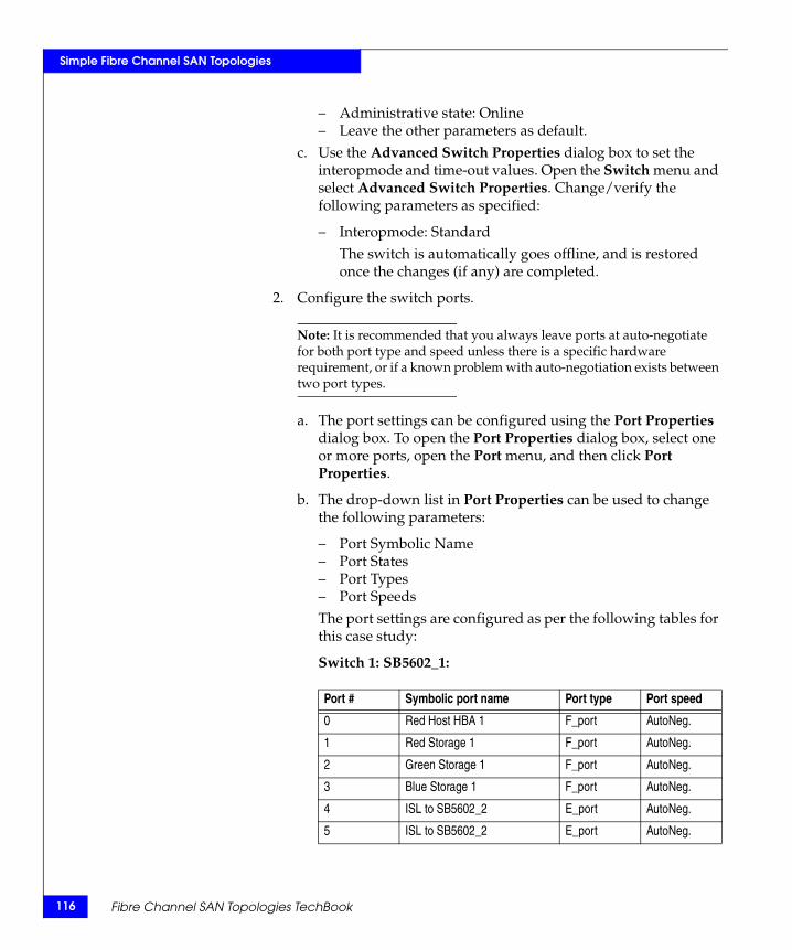
116
Simple Fibre Channel SAN Topologies
– Administrative state: Online– Leave the other parameters as default.
c. Use the Advanced Switch Properties dialog box to set the interopmode and time-out values. Open the Switch menu and select Advanced Switch Properties. Change/verify the following parameters as specified:
– Interopmode: StandardThe switch is automatically goes offline, and is restored once the changes (if any) are completed.
2. Configure the switch ports.
Note: It is recommended that you always leave ports at auto-negotiate for both port type and speed unless there is a specific hardware requirement, or if a known problem with auto-negotiation exists between two port types.
a. The port settings can be configured using the Port Properties dialog box. To open the Port Properties dialog box, select one or more ports, open the Port menu, and then click Port Properties.
b. The drop-down list in Port Properties can be used to change the following parameters:
– Port Symbolic Name– Port States– Port Types– Port SpeedsThe port settings are configured as per the following tables for this case study:
Switch 1: SB5602_1:
Port # Symbolic port name Port type Port speed
0 Red Host HBA 1 F_port AutoNeg.
1 Red Storage 1 F_port AutoNeg.
2 Green Storage 1 F_port AutoNeg.
3 Blue Storage 1 F_port AutoNeg.
4 ISL to SB5602_2 E_port AutoNeg.
5 ISL to SB5602_2 E_port AutoNeg.
Fibre Channel SAN Topologies TechBook
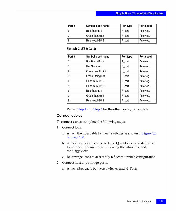
Simple Fibre Channel SAN Topologies
Switch 2: SB5602_2:
Repeat Step 1 and Step 2 for the other configured switch.
Connect cables
To connect cables, complete the following steps:
1. Connect ISLs.
a. Attach the fiber cable between switches as shown in Figure 12 on page 108.
b. After all cables are connected, use Quicktools to verify that all ISL connections are up by reviewing the fabric tree and topology view.
c. Re-arrange icons to accurately reflect the switch configuration.
2. Connect host and storage ports.
a. Attach fiber cable between switches and N_Ports.
6 Blue Storage 2 F_port AutoNeg.
7 Green Storage 2 F_port AutoNeg.
8 Blue Host HBA 2 F_port AutoNeg.
Port # Symbolic port name Port type Port speed
0 Red Host HBA 2 F_port AutoNeg.
1 Red Storage 2 F_port AutoNeg.
2 Green Host HBA 2 F_port AutoNeg.
3 Green Storage 31 F_port AutoNeg.
4 ISL to SB5602_2 E_port AutoNeg.
5 ISL to SB5602_2 E_port AutoNeg.
6 Blue Storage 1 F_port AutoNeg.
7 Green Storage 4 F_port AutoNeg.
8 Blue Host HBA 1 F_port AutoNeg.
Port # Symbolic port name Port type Port speed
Two switch fabrics 117

118
Simple Fibre Channel SAN Topologies
Zone hosts and storage
To zone hosts and storage, complete the following steps:
1. Before creating any zones and enabling zoning, use the Edit Zoning config dialog box to change the Interop Auto save, Default Zone, and Discard inactive parameters.
• The Interop Auto save parameter (which determines whether any active zone changes that a switch receives from any other switch in the fabric must be saved to the zoning database of the switch) must be set to False.
• The Default Zone (which allows all N_Ports to see each other in the absence of any active zones) must be set to False.
• The Discard inactive parameter (which automatically removes or pulls out inactive zones from an active zoneset) must be set to False.
2. Open the Edit Zoning toolbar from the Zoning menu on the faceplate display.
3. Create a zone by clicking Create Zone.
4. Provide a descriptive name for the zone. This example zones “Red host HBA 1” and “Red Storage 1”.Type “RedHBA1_1470_8aa" and then press Enter.
5. Locate, then click, “Red Host HBA 1” (WWPN 10000000c938e554) in the potential zone members list.
6. Click Add Member to add the selected HBA to the zone created in Step 4.
7. Locate, then click, “Red Storage 1” (WWPN 50060482cc19bf87) in the potential zone members list.
8. Repeat Step 3 through Step 7 for all host and storage pairs in the environment.
9. Create a zone set by clicking Create Zone Set.
10. Provide a descriptive name for the zone set. This example will use the date of “Oct_31_06_1140”.
11. Add all of the zones created in Step 4 through Step 8 to the zone set by dragging the zones listed to the left into the zoneset created in Step 10.
Fibre Channel SAN Topologies TechBook
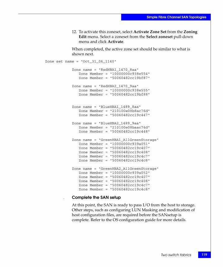
Simple Fibre Channel SAN Topologies
12. To activate this zoneset, select Activate Zone Set from the Zoning Edit menu. Select a zoneset from the Select zoneset pull-down menu and click Activate.
When completed, the active zone set should be similar to what is shown next.
Zone set name = "Oct_31_06_1140"
Zone name = "RedHBA1_1470_8aa"Zone Member = "10000000c938e554"Zone Member = "50060482cc19bf87"
Zone name = "RedHBA2_1470_9aa"Zone Member = "10000000c938e555"Zone Member = "50060482cc19bf88"
Zone name = "BlueHBA1_1489_8aa"Zone Member = "210100e08b8ac76d"Zone Member = "50060482cc19c447"
Zone name = "BlueHBA2_1489_9aa"Zone Member = "210100e08baac76d"Zone Member = "50060482cc19c448"
Zone name = "GreenHBA1_AllGreenStorage"Zone Member = "10000000c939a051"Zone Member = "50060482cc19c407"Zone Member = "50060482cc19c408"Zone Member = "50060482cc19c4c7"Zone Member = "50060482cc19c4c8"
Zone name = "GreenHBA2_AllGreenStorage"Zone Member = "10000000c939a052"Zone Member = "50060482cc19c407"Zone Member = "50060482cc19c408"Zone Member = "50060482cc19c4c7"Zone Member = "50060482cc19c4c8"
. Complete the SAN setup
At this point, the SAN is ready to pass I/O from the host to storage. Other steps, such as configuring LUN Masking and modification of host configuration files, are required before the SANsetup is complete. Refer to the OS configuration guide for more details.
Two switch fabrics 119
120
Simple Fibre Channel SAN Topologies
Blade switch with direct attached storageA blade server with two embedded FC switch modules directly attached to storage complies with the definition of a simple two-switch, one-hop SAN model. Before discussing the general layout of this topology type, it is interesting to note how the use of a blade server can simplify a desired two switch-one hop SAN design.
Consider the following scenario:
An end-user needs to hook up ten independent servers to storage using two departmental switches. Each of the ten servers needs its own power supply, cooling mechanism, and cabling. These aspects must also be considered for the departmental switches. This whole two-tier set up can be replaced by a 7U blade server chassis which can house at least ten independent servers, depending on the vendor type (IBM, Dell, HP, and so on). The chassis contains the power, cooling, and cabling components, and often incorporates a network switch. The blades within a single chassis can still run different applications and play independent roles.
The chassis also provides the ability to embed a pair of FC switch modules with a maximum of six external ports, depending on the vendor (Brocade, Brocade M series, or QLogic), which can be attached to an external fabric, or in this case, the storage. Each switch module is internally connected to each of the blade servers in the blade server chassis. The behavior, features, and management of the switch modules are similar to those of departmental stand-alone edge switches.
The detailed blade server concept, its value to the FC SAN world, the basic architecture, and the various EMC-supported blade switch modules are further discussed in the Extended Distance Technologies TechBook, available through the E-Lab Interoperability Navigator, Topology Resource Center tab, at http://elabnavigator.EMC.com.
With this in mind, this example examines the general layout of a blade server switch module directly attached to storage. Figure 13 on page 121 is divided into two parts. The left side (a) represents the blade server chassis directly attached to storage through the switch modules, while the right side (b) represents the two-tier FC SAN to which it is equivalent.
Fibre Channel SAN Topologies TechBook
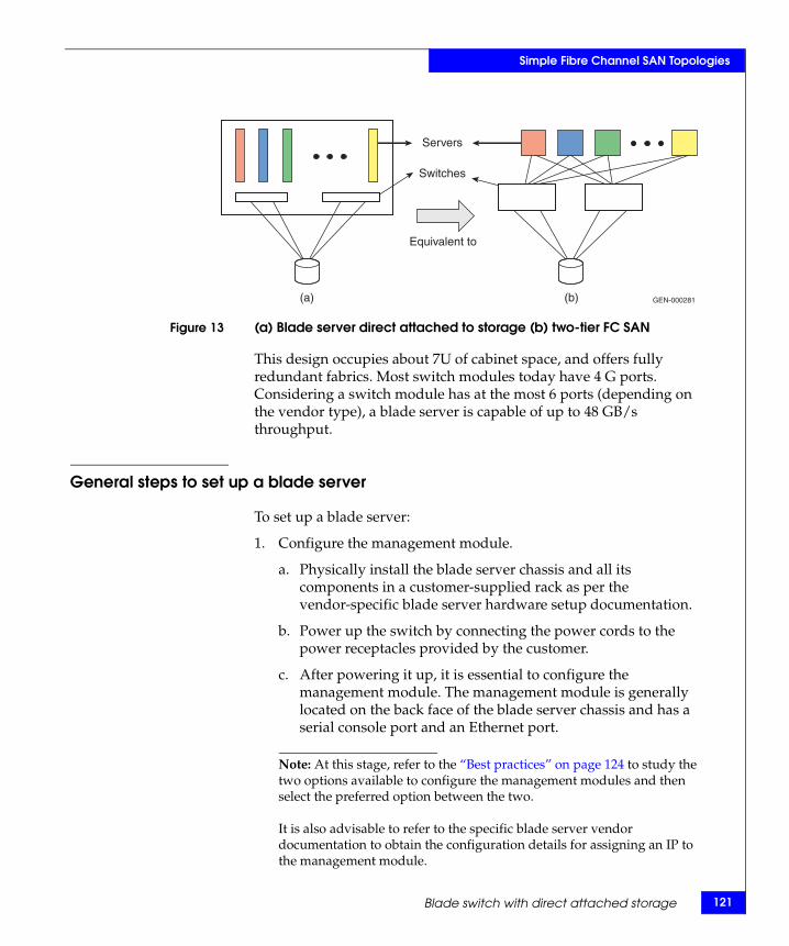
Simple Fibre Channel SAN Topologies
Figure 13 (a) Blade server direct attached to storage (b) two-tier FC SAN
This design occupies about 7U of cabinet space, and offers fully redundant fabrics. Most switch modules today have 4 G ports. Considering a switch module has at the most 6 ports (depending on the vendor type), a blade server is capable of up to 48 GB/s throughput.
General steps to set up a blade server
To set up a blade server:
1. Configure the management module.
a. Physically install the blade server chassis and all its components in a customer-supplied rack as per the vendor-specific blade server hardware setup documentation.
b. Power up the switch by connecting the power cords to the power receptacles provided by the customer.
c. After powering it up, it is essential to configure the management module. The management module is generally located on the back face of the blade server chassis and has a serial console port and an Ethernet port.
Note: At this stage, refer to the “Best practices” on page 124 to study the two options available to configure the management modules and then select the preferred option between the two.
It is also advisable to refer to the specific blade server vendor documentation to obtain the configuration details for assigning an IP to the management module.
Equivalent to
Servers
Switches
(a) (b) GEN-000281
Blade switch with direct attached storage 121
122
Simple Fibre Channel SAN Topologies
There are also different options to consider while doing this at data centers (for example, whether it is advisable to have the payload LAN and management LAN on the same LAN segment, and so on).
d. In general, if configuring the management module through the serial console using the Hyperterminal application, it is essential to gather the following information:
– Connection type: COM 1 or COM 3– Other settings:
– Bits per second– Data bits– Parity bits– Stop bits
If configuring the management through the Ethernet port, that is, through Telnet, the following information is required:
– Default IP of management module– Default username– Default password
e. Once configured, the management module can be used to configure the other modules including the I/O modules.
2. Configure the other modules and the server blades.
a. To configure other modules:
Once the management module is configured with an IP address, it can be accessed through CLI or a Web interface in most cases, and can be used to configure, or rather assign, IPs to the other I/O modules, such as fibre channel switch modules (FCSM), and the Ethernet module if required.
b. To configure the server blades:
Generally, when supplied from the vendor, the server blades are configured for a network internal to the blade server chassis. Most blade servers today have VGA and USB connectors on the server blade which can be used to access and configure the server blades. The desired OS can be installed on the blade using these means of access, and on completing this installation, the other features, such as IP address, etc., can be set up for the server blades.
Fibre Channel SAN Topologies TechBook
Simple Fibre Channel SAN Topologies
3. Check the following switch module configuration settings:
a. The mode of operation: The switch modules must be in their respective native mode for this kind of a configuration.
– Desired mode on Brocade switch module: Brocade native mode (interopmode 0)
– Desired mode on Brocade M series switch module: Brocade M series Fabric mode 1.0
– Desired mode on QLogic switch module: Standard modeb. Domain ID settings:
– Domain ID range for Brocade switch modules: 1 – 239 – Domain ID range for Brocade M series switch modules:
1 – 31– Domain ID range for QLogic switch modules: 97 – 127
c. Ensure that the switch firmware revision and the switch management application are supported versions.
d. If default zoning enabled does not allow the host ports to communicate with the storage ports, then the appropriate WWNN or WWPN zoning needs to be performed to establish connectivity. As a result, the server blades can log into the storage and read from or write to the respective storage devices it is mapped to.
– Default zoning on the Brocade module restricts the initiator (host) ports to see or communicate with the target (storage) ports. Therefore, zoning must be configured on the Brocade modules.
– Default zoning on the Brocade M series module restricts the initiator (host) ports to see or communicate with the target (storage) ports. Therefore, zoning must be configured on the Brocade M series modules.
– Default zoning on the QLogic module allows the initiator (host) ports to see or communicate with the target (storage) ports. Therefore, zoning need not be configured on the QLogic modules.
4. Ensure switch module connectivity (physical).
Blade switch with direct attached storage 123
124
Simple Fibre Channel SAN Topologies
The switch modules must be connected directly to the storage using FC cables. EMC recommends at least two connections between any two FC components in a SAN. In this case, at least four cables must be connected in total: two from each switch module to the respective storage ports.
The switch modules, as previously stated, are internally connected to each of the blade servers. Thus, a specific number of ports on each switch, depending on the number of server blades the blade server chassis can house, are dedicated F_ports, while the other external ports are G_ports. For this topology, these ports can be configured as F_ports since they will be hooked up to storage.
5. Use CLI/Web GUI to verify connectivity.
The switch module CLI or switch management application can be used to verify that the physical connectivity was successful and that the switch can see the storage ports. The name server information can be obtained at this time so as to confirm whether all the N_Ports: HBA ports from the server blades and the storage ports, show up.
Best practicesFor general best practices, refer to “Best practices” on page 23. The following best practices are recommended for configuring the blade server and setting up the direct attach to storage:
◆ There are two options available to access the management functions of the FC switch modules through the link to the management module. Option 1 is recommended for easy access and management of the switch module.
• Option 1: If the IP address assigned to the switch is within the subnet of the management module, then the switch management functions can be accessed without launching the Management Module GUI.
• Option 2: If the IP address assigned to the switch is not within the subnet of the management module, then the switch management functions can be accessed only by launching the Management Module GUI and then navigating to the specific functions.
Fibre Channel SAN Topologies TechBook
Simple Fibre Channel SAN Topologies
◆ Connect each switch module to storage ports that are mapped to the same set of storage devices. Thus, each server blade can access the storage ports it is zoned with using two paths, each path passing through a different switch module. If either of the switch modules goes down, the server continues to have access to the storage port it is zoned with and there is no disruption in traffic between the server and storage.
◆ Always check supported switch module firmware release notes for caveats on direct attach to storage, if any.
Host and storage layout
For general host and storage layout information, refer to “Host and storage layout” on page 30. The following information is specific to blade servers.
There is little an end-user can do with the host and storage layout in the case of a blade server since the architecture allows every server blade in the blade server chassis to access both the switch modules. As a result, even if a storage port is hooked up to one of the switch modules, all the server blades can access the storage port through the switch module unless, and until, any of the internal or external ports on the switch modules are blocked to prevent access between the server and storage in this case. However, zoning can take care of the access settings.
Switch and fabric management
For general switch and fabric information, refer to “Switch and fabric management” on page 32. The following information is specific to blade switches.
It is recommended that end-users use the supported vendor specific web application and CLI for managing the switch.
◆ The Brocade modules can be managed using Brocade CLI or Web Tools.
◆ The Brocade M series modules can be managed using Brocade M series SAN browser.
◆ The QLogic modules can be managed using the QLogic CLI or QLogic SAN surfer.
Blade switch with direct attached storage 125
126
Simple Fibre Channel SAN Topologies
SecurityFor general information on security, refer to “Security” on page 36. Specific information for this example follows. For further information on security, refer to the Building Secure SANs TechBook, available through the E-Lab Interoperability Navigator, Topology Resource Center tab, at http://elabnavigator.EMC.com.
◆ Blade servers usually exist in the “access layer” of a data center architecture and have specific requirements for security. These mainly deal with establishing secure access to switch, protection against attacks, and identifying users and other servers that are accessing the network. For easy configuration, management, and control, many capabilities, such as firewalls, are consolidated in the embedded switches in this example.
◆ The access to the embedded switch must be secured. This requires specific features, such as SSHv2 or RADIUS. Both protocols are means of securing connectivity to access the management interface of the switch. Without these capabilities, it would be considerably easier for an unauthorized user to change the configuration of the switch thus affecting the blade server’s performance.
◆ The switch must also provide capabilities to prevent, as well as defend against network attacks. This is enabled by the following features: Port security (limited number of MAC addresses per port), MAC address notification (whether MAC address has moved), DARP inspection (ties a port to an ARP request, helping to ensure that a default gateway cannot be spoofed), IP source guard (Protects against IP being spoofed).
◆ An access layer switch must make sure that the network allows only authorized devices to connect to it.
Security features on blade server FC switch modules include:
◆ ISL and ELS authentication, as defined in FC-SP, provide a means to authenticate the identity of a connected switch, host or target and/or authorize a list of devices to join a fabric.
◆ ISL security is supported on E_Ports. ELS security is supported on F_Ports.
◆ Fabric Binding, Port Binding, and Switch Binding are introduced as a means to control the switch composition of a fabric. They may be enabled on the respective vendor switch modules using
Fibre Channel SAN Topologies TechBook
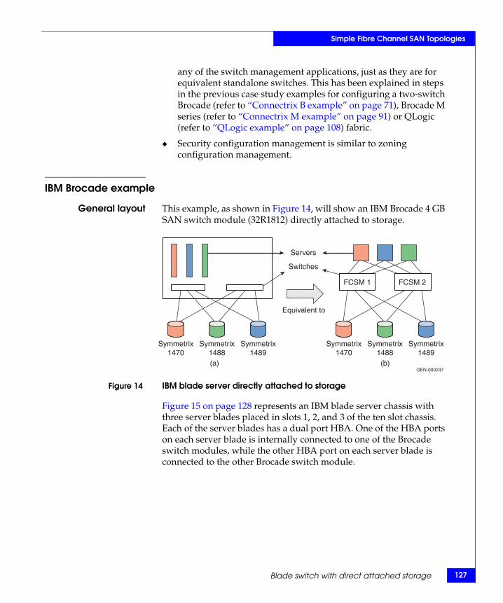
Simple Fibre Channel SAN Topologies
any of the switch management applications, just as they are for equivalent standalone switches. This has been explained in steps in the previous case study examples for configuring a two-switch Brocade (refer to “Connectrix B example” on page 71), Brocade M series (refer to “Connectrix M example” on page 91) or QLogic (refer to “QLogic example” on page 108) fabric.
◆ Security configuration management is similar to zoning configuration management.
IBM Brocade example
General layout This example, as shown in Figure 14, will show an IBM Brocade 4 GB SAN switch module (32R1812) directly attached to storage.
Figure 14 IBM blade server directly attached to storage
Figure 15 on page 128 represents an IBM blade server chassis with three server blades placed in slots 1, 2, and 3 of the ten slot chassis. Each of the server blades has a dual port HBA. One of the HBA ports on each server blade is internally connected to one of the Brocade switch modules, while the other HBA port on each server blade is connected to the other Brocade switch module.
Symmetrix1470
Symmetrix1488
Symmetrix1489
Equivalent to
Servers
Switches
FCSM 1 FCSM 2
Symmetrix1470
Symmetrix1488
Symmetrix1489
(a) (b)GEN-000247
Blade switch with direct attached storage 127
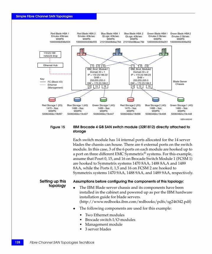
128
Simple Fibre Channel SAN Topologies
Figure 15 IBM Brocade 4 GB SAN switch module (32R1812) directly attached to storage
Each switch module has 14 internal ports allocated for the 14 server blades the chassis can house. There are 6 external ports on the switch module. In this case, 3 of the 6 ports on each module are hooked up to a port on three different EMC Symmetrix® systems. For this example, assume that Posrt 0, 15, and 16 on Brocade Switch Module 1 (FCSM 1) are hooked to Symmetrix systems 1470 8AA, 1488 8A,A and 1489 8AA, while the Ports 0, 1,5 and 16 on FCSM 2 are hooked to Symmetrix systems 1470 9AA, 1488 9AA, and 1489 9AA, respectively.
Setting up thistopology
Assumptions before configuring the components of this topology:
◆ The IBM Blade server chassis and its components have been installed in the cabinet and powered up as per the IBM hardware installation guide for blade servers. (http://www.redbooks.ibm.com/redbooks/pdfs/sg246342.pdf)
◆ The following components are used for this example:
• Two Ethernet modules • Brocade switch I/O modules • Management module• 3 server blades
IBM_Brcd_Module1Domain ID = 1
IP = 172.23.199.22SnM =
255.255.255.0GW = 172.23.199.2
.x
Red Blade HBA 1Emulex 4Gb/sec
WWPN10000000c938e554
Red Blade HBA 2Emulex 4Gb/sec
WWPN10000000c938e555
Green Blade HBA 1Emulex 2 Gb/sec
WWPN10000000c939a051
Green Blade HBA 2Emulex 2 Gb/sec
WWPN10000000c939a052
Blue Blade HBA 1QLogic 4Gb/sec
WWPN210100e08b8ac76d
Blue Blade HBA 2QLogic 4Gb/sec
WWPN210100e08baac76d
Red Storage 2 (2G)1470 – 9aa
WWPN50060482cc19bf88
Red Storage 1 (2G)1470 – 8aa
WWPN50060482cc19bf87
Blue Storage 1 (4G)1488 – 8aa
WWPN50060482cc19c407
Blue Storage 2 (4G)1488 – 9aa
WWPN50060482cc19c408
1 32
0 16
IBM_Brcd_Module2Domain ID = 2
IP = 172.23.199.23SnM =
255.255.255.0GW = 172.23.199.2
1 32
0 15
Blade Server Chassis
Green Storage 1 (4G)1489 – 8aa
WWPN50060482cc19c447
Green Storage 1 (4G)1489 – 9aa
WWPN50060482cc19c448
15 16
Key:FC (Block I/O)Ethernet (Management)
Ethernet Hub
172.23.199network drop
GEN-000249
Fibre Channel SAN Topologies TechBook
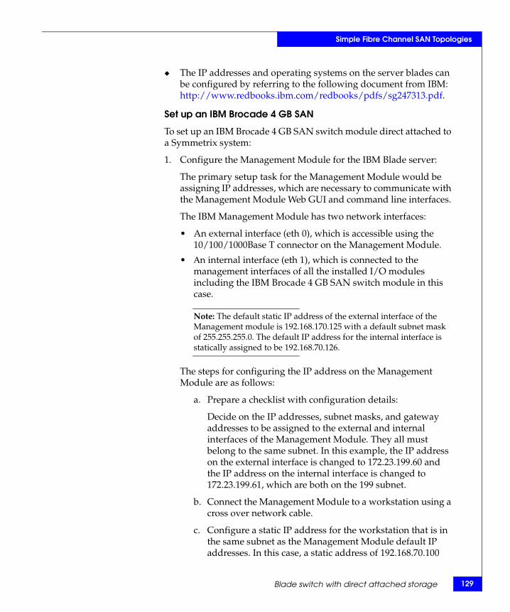
Simple Fibre Channel SAN Topologies
◆ The IP addresses and operating systems on the server blades can be configured by referring to the following document from IBM: http://www.redbooks.ibm.com/redbooks/pdfs/sg247313.pdf.
Set up an IBM Brocade 4 GB SAN
To set up an IBM Brocade 4 GB SAN switch module direct attached to a Symmetrix system:
1. Configure the Management Module for the IBM Blade server:
The primary setup task for the Management Module would be assigning IP addresses, which are necessary to communicate with the Management Module Web GUI and command line interfaces.
The IBM Management Module has two network interfaces:
• An external interface (eth 0), which is accessible using the 10/100/1000Base T connector on the Management Module.
• Αn internal interface (eth 1), which is connected to the management interfaces of all the installed I/O modules including the IBM Brocade 4 GB SAN switch module in this case.
Note: The default static IP address of the external interface of the Management module is 192.168.170.125 with a default subnet mask of 255.255.255.0. The default IP address for the internal interface is statically assigned to be 192.168.70.126.
The steps for configuring the IP address on the Management Module are as follows:
a. Prepare a checklist with configuration details:
Decide on the IP addresses, subnet masks, and gateway addresses to be assigned to the external and internal interfaces of the Management Module. They all must belong to the same subnet. In this example, the IP address on the external interface is changed to 172.23.199.60 and the IP address on the internal interface is changed to 172.23.199.61, which are both on the 199 subnet.
b. Connect the Management Module to a workstation using a cross over network cable.
c. Configure a static IP address for the workstation that is in the same subnet as the Management Module default IP addresses. In this case, a static address of 192.168.70.100
Blade switch with direct attached storage 129
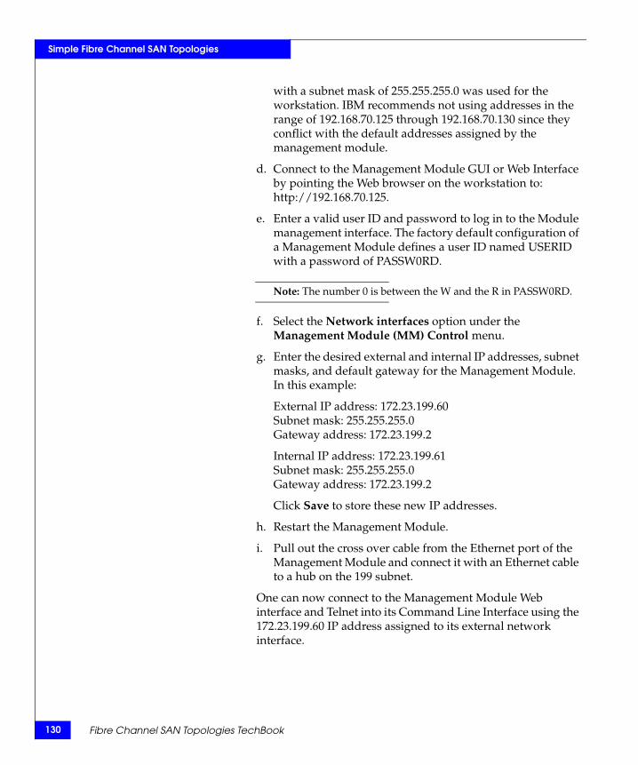
130
Simple Fibre Channel SAN Topologies
with a subnet mask of 255.255.255.0 was used for the workstation. IBM recommends not using addresses in the range of 192.168.70.125 through 192.168.70.130 since they conflict with the default addresses assigned by the management module.
d. Connect to the Management Module GUI or Web Interface by pointing the Web browser on the workstation to: http://192.168.70.125.
e. Enter a valid user ID and password to log in to the Module management interface. The factory default configuration of a Management Module defines a user ID named USERID with a password of PASSW0RD.
Note: The number 0 is between the W and the R in PASSW0RD.
f. Select the Network interfaces option under the Management Module (MM) Control menu.
g. Enter the desired external and internal IP addresses, subnet masks, and default gateway for the Management Module. In this example:
External IP address: 172.23.199.60Subnet mask: 255.255.255.0Gateway address: 172.23.199.2
Internal IP address: 172.23.199.61Subnet mask: 255.255.255.0Gateway address: 172.23.199.2
Click Save to store these new IP addresses.
h. Restart the Management Module.
i. Pull out the cross over cable from the Ethernet port of the Management Module and connect it with an Ethernet cable to a hub on the 199 subnet.
One can now connect to the Management Module Web interface and Telnet into its Command Line Interface using the 172.23.199.60 IP address assigned to its external network interface.
Fibre Channel SAN Topologies TechBook
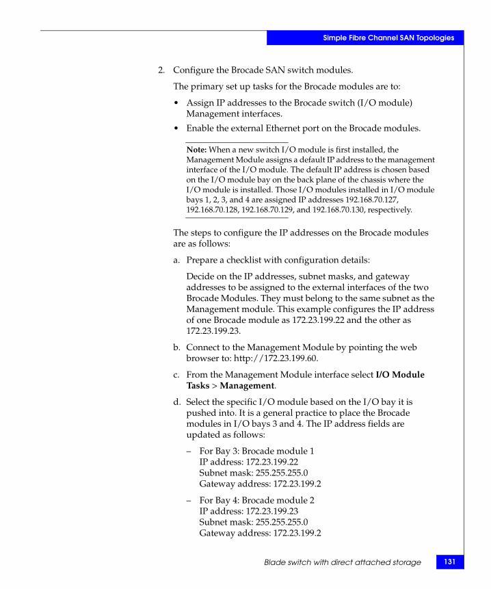
Simple Fibre Channel SAN Topologies
2. Configure the Brocade SAN switch modules.
The primary set up tasks for the Brocade modules are to:
• Assign IP addresses to the Brocade switch (I/O module) Management interfaces.
• Enable the external Ethernet port on the Brocade modules.
Note: When a new switch I/O module is first installed, the Management Module assigns a default IP address to the management interface of the I/O module. The default IP address is chosen based on the I/O module bay on the back plane of the chassis where the I/O module is installed. Those I/O modules installed in I/O module bays 1, 2, 3, and 4 are assigned IP addresses 192.168.70.127, 192.168.70.128, 192.168.70.129, and 192.168.70.130, respectively.
The steps to configure the IP addresses on the Brocade modules are as follows:
a. Prepare a checklist with configuration details:
Decide on the IP addresses, subnet masks, and gateway addresses to be assigned to the external interfaces of the two Brocade Modules. They must belong to the same subnet as the Management module. This example configures the IP address of one Brocade module as 172.23.199.22 and the other as 172.23.199.23.
b. Connect to the Management Module by pointing the web browser to: http://172.23.199.60.
c. From the Management Module interface select I/O Module Tasks > Management.
d. Select the specific I/O module based on the I/O bay it is pushed into. It is a general practice to place the Brocade modules in I/O bays 3 and 4. The IP address fields are updated as follows:
– For Bay 3: Brocade module 1IP address: 172.23.199.22Subnet mask: 255.255.255.0Gateway address: 172.23.199.2
– For Bay 4: Brocade module 2IP address: 172.23.199.23Subnet mask: 255.255.255.0Gateway address: 172.23.199.2
Blade switch with direct attached storage 131
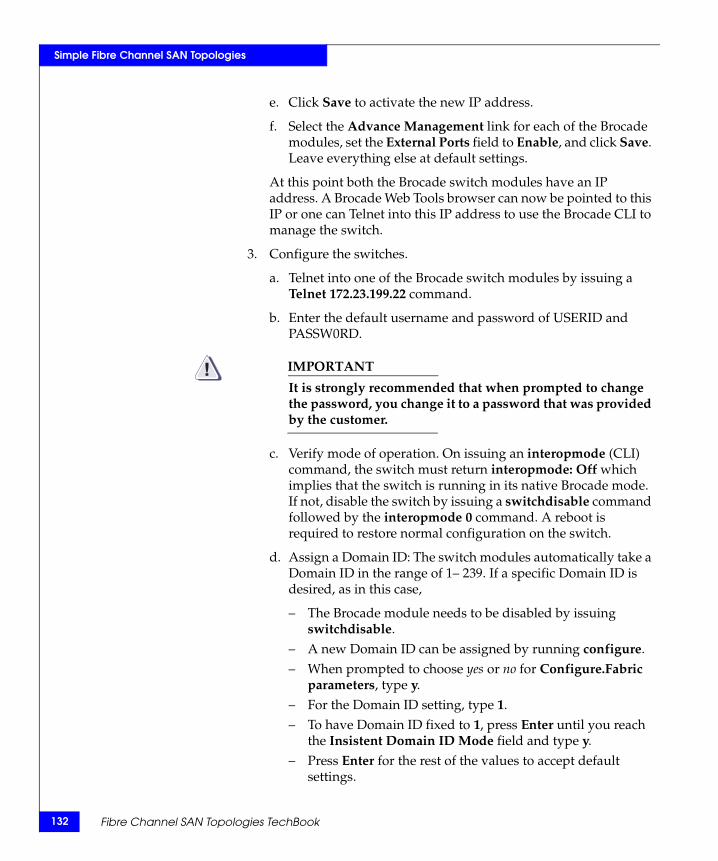
132
Simple Fibre Channel SAN Topologies
e. Click Save to activate the new IP address.
f. Select the Advance Management link for each of the Brocade modules, set the External Ports field to Enable, and click Save. Leave everything else at default settings.
At this point both the Brocade switch modules have an IP address. A Brocade Web Tools browser can now be pointed to this IP or one can Telnet into this IP address to use the Brocade CLI to manage the switch.
3. Configure the switches.
a. Telnet into one of the Brocade switch modules by issuing a Telnet 172.23.199.22 command.
b. Enter the default username and password of USERID and PASSW0RD.
IMPORTANT!It is strongly recommended that when prompted to change the password, you change it to a password that was provided by the customer.
c. Verify mode of operation. On issuing an interopmode (CLI) command, the switch must return interopmode: Off which implies that the switch is running in its native Brocade mode. If not, disable the switch by issuing a switchdisable command followed by the interopmode 0 command. A reboot is required to restore normal configuration on the switch.
d. Assign a Domain ID: The switch modules automatically take a Domain ID in the range of 1– 239. If a specific Domain ID is desired, as in this case,
– The Brocade module needs to be disabled by issuing switchdisable.
– A new Domain ID can be assigned by running configure.– When prompted to choose yes or no for Configure.Fabric
parameters, type y.– For the Domain ID setting, type 1.– To have Domain ID fixed to 1, press Enter until you reach
the Insistent Domain ID Mode field and type y.– Press Enter for the rest of the values to accept default
settings.
Fibre Channel SAN Topologies TechBook
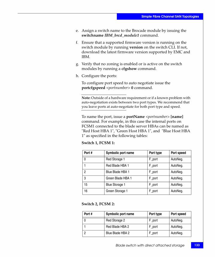
Simple Fibre Channel SAN Topologies
e. Assign a switch name to the Brocade module by issuing the switchname IBM_brcd_module1 command.
f. Ensure that a supported firmware version is running on the switch module by running version on the switch CLI. If not, download the latest firmware version supported by EMC and IBM.
g. Verify that no zoning is enabled or is active on the switch modules by running a cfgshow command.
h. Configure the ports:
To configure port speed to auto negotiate issue the portcfgspeed <portnumber> 0 command.
Note: Outside of a hardware requirement or if a known problem with auto-negotiation exists between two port types. We recommend that you leave ports at auto-negotiate for both port type and speed.
To name the port, issue a portName <portnumber> [name] command. For example, in this case the internal ports on FCSM1 connected to the blade server HBAs can be named as "Red Host HBA 1", "Green Host HBA 1", and "Blue Host HBA 1" as specified in the following tables:
Switch 1, FCSM 1:
Switch 2, FCSM 2:
Port # Symbolic port name Port type Port speed
0 Red Storage 1 F_port AutoNeg.
1 Red Blade HBA 1 F_port AutoNeg.
2 Blue Blade HBA 1 F_port AutoNeg.
3 Green Blade HBA 1 F_port AutoNeg.
15 Blue Storage 1 F_port AutoNeg.
16 Green Storage 1 F_port AutoNeg.
Port # Symbolic port name Port type Port speed
0 Red Storage 2 F_port AutoNeg.
1 Red Blade HBA 2 F_port AutoNeg.
2 Blue Blade HBA 2 F_port AutoNeg.
Blade switch with direct attached storage 133
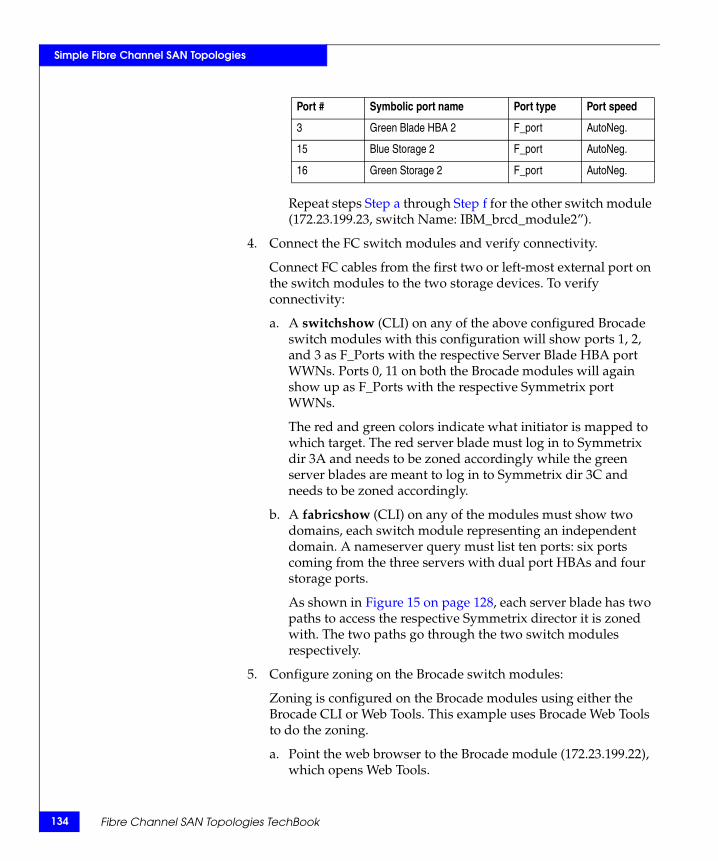
134
Simple Fibre Channel SAN Topologies
Repeat steps Step a through Step f for the other switch module (172.23.199.23, switch Name: IBM_brcd_module2”).
4. Connect the FC switch modules and verify connectivity.
Connect FC cables from the first two or left-most external port on the switch modules to the two storage devices. To verify connectivity:
a. A switchshow (CLI) on any of the above configured Brocade switch modules with this configuration will show ports 1, 2, and 3 as F_Ports with the respective Server Blade HBA port WWNs. Ports 0, 11 on both the Brocade modules will again show up as F_Ports with the respective Symmetrix port WWNs.
The red and green colors indicate what initiator is mapped to which target. The red server blade must log in to Symmetrix dir 3A and needs to be zoned accordingly while the green server blades are meant to log in to Symmetrix dir 3C and needs to be zoned accordingly.
b. A fabricshow (CLI) on any of the modules must show two domains, each switch module representing an independent domain. A nameserver query must list ten ports: six ports coming from the three servers with dual port HBAs and four storage ports.
As shown in Figure 15 on page 128, each server blade has two paths to access the respective Symmetrix director it is zoned with. The two paths go through the two switch modules respectively.
5. Configure zoning on the Brocade switch modules:
Zoning is configured on the Brocade modules using either the Brocade CLI or Web Tools. This example uses Brocade Web Tools to do the zoning.
a. Point the web browser to the Brocade module (172.23.199.22), which opens Web Tools.
3 Green Blade HBA 2 F_port AutoNeg.
15 Blue Storage 2 F_port AutoNeg.
16 Green Storage 2 F_port AutoNeg.
Port # Symbolic port name Port type Port speed
Fibre Channel SAN Topologies TechBook
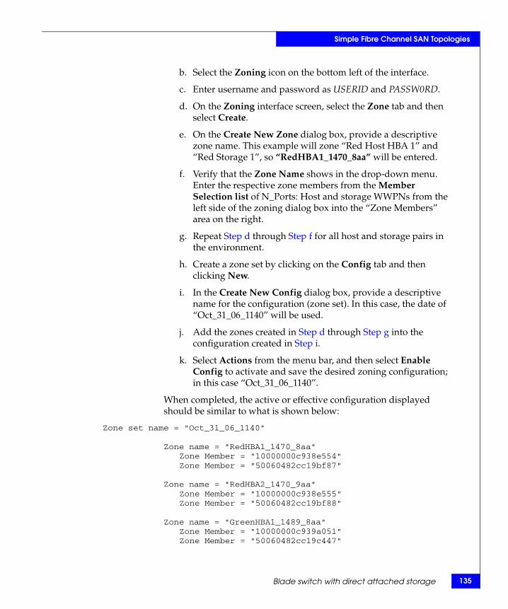
Simple Fibre Channel SAN Topologies
b. Select the Zoning icon on the bottom left of the interface.
c. Enter username and password as USERID and PASSW0RD.
d. On the Zoning interface screen, select the Zone tab and then select Create.
e. On the Create New Zone dialog box, provide a descriptive zone name. This example will zone “Red Host HBA 1” and “Red Storage 1”, so “RedHBA1_1470_8aa” will be entered.
f. Verify that the Zone Name shows in the drop-down menu. Enter the respective zone members from the Member Selection list of N_Ports: Host and storage WWPNs from the left side of the zoning dialog box into the “Zone Members” area on the right.
g. Repeat Step d through Step f for all host and storage pairs in the environment.
h. Create a zone set by clicking on the Config tab and then clicking New.
i. In the Create New Config dialog box, provide a descriptive name for the configuration (zone set). In this case, the date of “Oct_31_06_1140” will be used.
j. Add the zones created in Step d through Step g into the configuration created in Step i.
k. Select Actions from the menu bar, and then select Enable Config to activate and save the desired zoning configuration; in this case “Oct_31_06_1140”.
When completed, the active or effective configuration displayed should be similar to what is shown below:
Zone set name = "Oct_31_06_1140"
Zone name = "RedHBA1_1470_8aa"Zone Member = "10000000c938e554"Zone Member = "50060482cc19bf87"
Zone name = "RedHBA2_1470_9aa"Zone Member = "10000000c938e555"Zone Member = "50060482cc19bf88"
Zone name = "GreenHBA1_1489_8aa"Zone Member = "10000000c939a051"Zone Member = "50060482cc19c447"
Blade switch with direct attached storage 135
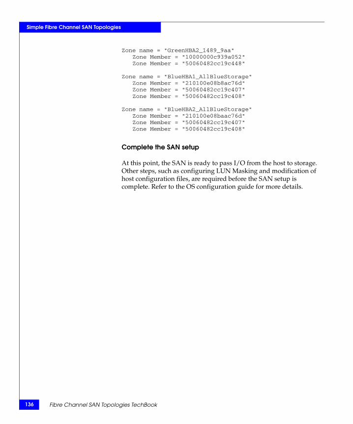
136
Simple Fibre Channel SAN Topologies
Zone name = "GreenHBA2_1489_9aa"Zone Member = "10000000c939a052"Zone Member = "50060482cc19c448"
Zone name = "BlueHBA1_AllBlueStorage"Zone Member = "210100e08b8ac76d"Zone Member = "50060482cc19c407"Zone Member = "50060482cc19c408"
Zone name = "BlueHBA2_AllBlueStorage"Zone Member = "210100e08baac76d"Zone Member = "50060482cc19c407"Zone Member = "50060482cc19c408"
Complete the SAN setup
At this point, the SAN is ready to pass I/O from the host to storage. Other steps, such as configuring LUN Masking and modification of host configuration files, are required before the SAN setup is complete. Refer to the OS configuration guide for more details.
Fibre Channel SAN Topologies TechBook
3Invisible Body Tag
This chapter provides the following information on complex Fibre Channel SAN topologies.
◆ Best practices..................................................................................... 138◆ Four switch full mesh...................................................................... 139◆ Compound core edge switches ...................................................... 192◆ Heterogeneous switch interoperability......................................... 250◆ Distance extension case studies ..................................................... 362
Complex FibreChannel SAN
Topologies
Complex Fibre Channel SAN Topologies 137
138
Complex Fibre Channel SAN Topologies
Best practicesGeneral best practices for simple and complex Fibre Channel SAN topologies are described in “Best practices” on page 23. The information in this section is specific to complex Fibre Channel SAN topologies only.
ISL subscription
While planning the SAN, keep track of how many host and storage pairs will be utilizing the ISLs between domains. As a general best practice, if two switches will be connected by ISLs, ensure that there is a minimum of two ISLs between them and that there are no more than six initiator and target pairs per ISL. For example, if 14 initiators access a total of 14 targets between two domains, a total of three ISLs would be necessary. Consider the applications that will use the ISLs before applying this best practice when setting up a configuration.
Host and storage layout
For host and storage layout information for both simple and complex Fibre Channel SAN topologies, refer to “Host and storage layout” on page 30.
Switch and fabric management
For switch and fabric management information for both simple and complex Fibre Channel SAN topologies, refer to “Switch and fabric management” on page 32.
Security
It is important to secure your fabric. For general information on security, refer to “Security” on page 36. For more information on security, refer to the Building Secure SANs TechBook, available through the E-Lab Interoperability Navigator, Topology Resource Center tab, at http://elabnavigator.EMC.com.
Fibre Channel SAN Topologies TechBook
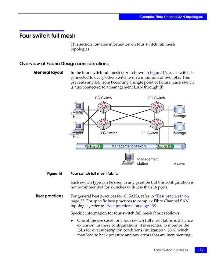
Complex Fibre Channel SAN Topologies
Four switch full meshThis section contains information on four switch full mesh topologies.
Overview of Fabric Design considerations
General layout In the four switch full mesh fabric shown in Figure 16, each switch is connected to every other switch with a minimum of two ISLs. This prevents any ISL from becoming a single point of failure. Each switch is also connected to a management LAN through IP.
Figure 16 Four switch full mesh fabric
Each switch type can be used in any position but this configuration is not recommended for switches with less than 16 ports.
Best practices For general best practices for all SANs, refer to “Best practices” on page 23. For specific best practices to complex Fibre Channel SAN topologies, refer to “Best practices” on page 138.
Specific information for four switch full mesh fabrics follows.
◆ One of the use cases for a four switch full mesh fabric is distance extension. In these configurations, it is essential to monitor the ISLs for oversubscription conditions (utilization > 80%) which may lead to back pressure and any errors that are incrementing,
Management network
GEN-000222
FC Switch
FC Switch
FC Switch
FC Switch
Host
Host
Storage
Storage
Managementstation
Subnet A Subnet B
Four switch full mesh 139
140
Complex Fibre Channel SAN Topologies
especially bit errors or invalid transmission words, as these may lead to credit starvation. For more information on credit starvation, refer to “Buffer-to-buffer credit information” in the Extended Distance Technologies TechBook, available through the E-Lab Interoperability Navigator, Topology Resource Center tab, at http://elabnavigator.EMC.com. See the individual case studies below for information on how to configure in each environment.
Host and storagelayout
Specific information for four switch full mesh fabrics follows.
◆ In the four switch fabric examples used in this section, hosts and storage can be connected to any switch, but should be connected to the same switch when possible. A notable exception to this is in a distance extension environment when the switches are used to aggregate many different connections over an ISL and provide additional BB_Credit. In this configuration, the whole point of having multiple switches is to use the ISLs.
For general information on host and storage layout or all SANs, refer to “Host and storage layout” on page 30.
Switch and fabricmanagement
For general information on switch and fabric management or all SANs, refer to “Switch and fabric management” on page 32.
Security For general information regarding security or all SANs, refer to “Security” on page 36. For more information on security, refer to the Building Secure SANs TechBook, available through the E-Lab Interoperability Navigator, Topology Resource Center tab, at http://elabnavigator.EMC.com.
Connectrix B example
General layout As shown in Figure 17 on page 141, a four switch full mesh fabric has been created by connecting each switch to every other switch in the fabric with two ISLs. Each switch is also connected to a Management LAN via Ethernet cables. There are three hosts (Red, Blue, and Green) as well as three sets of storage ports (also Red, Blue, or Green). The colors are intended to indicate which hosts access which storage ports. In addition to the CTPs, each ED-48000B contains the following three blades:
◆ Slot 1 — FC4-16
◆ Slot 2 — FC4-32
◆ Slot 3 — FR4-18i
Fibre Channel SAN Topologies TechBook
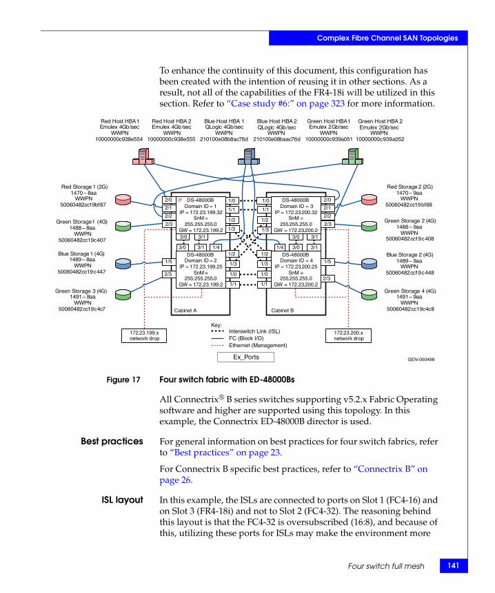
Complex Fibre Channel SAN Topologies
To enhance the continuity of this document, this configuration has been created with the intention of reusing it in other sections. As a result, not all of the capabilities of the FR4-18i will be utilized in this section. Refer to “Case study #6:” on page 323 for more information.
Figure 17 Four switch fabric with ED-48000Bs
All Connectrix® B series switches supporting v5.2.x Fabric Operating software and higher are supported using this topology. In this example, the Connectrix ED-48000B director is used.
Best practices For general information on best practices for four switch fabrics, refer to “Best practices” on page 23.
For Connectrix B specific best practices, refer to “Connectrix B” on page 26.
ISL layout In this example, the ISLs are connected to ports on Slot 1 (FC4-16) and on Slot 3 (FR4-18i) and not to Slot 2 (FC4-32). The reasoning behind this layout is that the FC4-32 is oversubscribed (16:8), and because of this, utilizing these ports for ISLs may make the environment more
GEN-000498
Key:
Domain ID = 1 IP = 172 . 23 . 199 . 32
SnM = 255 . 255 . 255 . 0
GW = 172 . 23 . 199 . 2
Domain ID = 2 IP = 172 . 23 . 199 . 25
SnM = 255 . 255 . 255 . 0
GW = 172 . 23 . 199 . 2
Domain ID = 4IP = 172 . 23 . 200 . 25
SnM = 255 . 255 . 255 . 0
GW = 172 . 23 . 200 . 2
Domain ID = 3IP = 172 . 23 . 200 . 32
SnM = 255 . 255 . 255 . 0
GW = 172 . 23 . 200 . 2
172.23.199.x network drop
Cabinet A Cabinet B
172.23.200.x network drop
Red Host HBA 1 Emulex 4 Gb / sec
WWPN 10000000 c 938 e 554
Red Host HBA 2 Emulex 4 Gb / sec
WWPN 10000000 c 938 e 555
Green Host HBA 1 Emulex 2 Gb / sec
WWPN 10000000 c 939 a 051
Green Host HBA 2 Emulex 2 Gb / sec
WWPN 10000000 c 939 a 052
Blue Host HBA 1QLogic 4 Gb / sec
WWPN 210100 e 08 b 8 ac 76 d
Blue Host HBA 2 QLogic 4 Gb / sec
WWPN 210100 e 08 baac 76 d
Red Storage 2 ( 2 G ) 1470 – 9 aa
WWPN 50060482 cc 19 bf 88
Red Storage 1 (2G)1470 – 8 aa
WWPN 50060482 cc 19 bf 87
Green Storage 1 ( 4 G ) 1488 – 8 aa
WWPN 50060482 cc 19 c 407
Green Storage 2 ( 4 G ) 1488 – 9 aa
WWPN 50060482 cc 19 c 408
Blue Storage 1 ( 4 G ) 1489 – 8 aa
WWPN 50060482 cc 19 c 447
Blue Storage 2 ( 4 G ) 1489 – 9 aa
WWPN 50060482 cc 19 c 448
Green Storage 3 ( 4 G ) 1491 – 8 aa
WWPN 50060482 cc 19 c 4 c 7
Green Storage 4 ( 4 G ) 1491 – 9 aa
WWPN 50060482 cc 19 c 4 c 8
1/0 1/0
1/1 1/1
3/0 3/1 1/4 1/4 3/0 3/1
3/0 3/1
1/0
1/1
1/3
1/2
1/2
1/3
1/2
1/3
1/2
1/3
1/0
1/1
2/2
2/1
2/0
2/3
2/2
2/1
2/0
2/3
1/5
2/3
3/0 3/1
1/5
2/3
Interswitch Link (ISL) FC (Block I/O) Ethernet (Management)
P
Ex_Ports
DS-48000B
DS-48000B
DS-48000B
DS-48000B
Four switch full mesh 141
142
Complex Fibre Channel SAN Topologies
susceptible to congestion and backpressure. The ISLs are spread out over two different blades to enhance fault tolerance and serviceability. ISLs destined to the same Domain are kept within the same port octet to take advantage of trunking.
Host and storagelayout
Both hosts and storage can be placed anywhere on the SAN. However in this example, we will try to conserve the ports on the FC4-16 and only use them for ISLs or host and storage pairs which could potentially utilize the full 4 Gb/s bandwidth. Host and storage pairs that cannot fully utilize the full 4 Gb/s bandwidth are placed onto the FC4-32 blade. For example, while the Red host HBAs are 4 Gb/sec, the storage ports they access are only 2 Gb/s. Because of this, they are placed onto the FC4-32. Similar reasoning is applied to the Green host since the HBAs are 2 Gb/s even though the storage ports are 4 Gb/sec. The Blue host and storage ports are all 4 Gb/s so they are placed on the FC4-16.
Note: It is not essential to configure the environment this way, but it does ensure that all resources are being efficiently utilized.
For general information on host and storage layout for four switch fabrics, refer to “Host and storage layout” on page 138.
Switch and fabricmanagement
In this example, CLI will be used to configure the environment, but Fabric Manager or Web Tools could also have been used.
For general information on switch and fabric management for four switch fabrics, refer to “Switch and fabric management” on page 138.
Security The connectivity and device discovery for a large Connectrix B switch fabric may be secured by appointing the following binding techniques. All these are Connectrix B specific features.
◆ Fabric Binding is a security method for restricting switches within a multiple-switch fabric. The SCC policy prevents unauthorized switches from joining a fabric. Switches are authenticated using digital certificates and unique private keys provided to the Switch Link Authentication Protocol (SLAP).
◆ Switch Binding is a security method for restricting devices that connect to a particular switch. If the device is another switch, this is handled by the SCC policy. If the device is a host or storage device, the Device Connection Control (DCC) policy binds those devices to a particular switch. Policies range from completely restrictive to reasonably flexible, based upon customer needs.
Fibre Channel SAN Topologies TechBook
Complex Fibre Channel SAN Topologies
◆ Port Binding is a security method for restricting host or storage devices that connect to particular switch ports. The DCC policy also binds device ports to switch ports. Policies range from completely restrictive to reasonably flexible, based on customer needs. For switches running Fabric OS v5.2.0 and later, the SCC ACL with strict fabric-wide consistency can also be used for Switch Binding in addition to the Secure Fabric OS mechanism.
The method to enable SCC and DCC policies has been provided in “Enabling the Switch Connection Policy (SCC)” on page 209.
For general information on security for four switch fabrics, refer to “Security” on page 138. Specific information for this example follows.
Setting up thistopology
Assumptions specific to this case study:
◆ The switches are installed in an EMC-supplied cabinet.
• For installation instructions, see Connectrix EC-1500 Cabinet Installation and Setup Manual, which can be accessed from Powerlink.
◆ The proper power receptacles have been provided by the customer.
• For switch power requirements, refer to the EMC Connectrix SAN Products Data Reference Manual, available through the E-Lab Interoperability Navigator, Topology Resource Center tab, at http://elabnavigator.EMC.com.
◆ The switches have not been connected to the power source and are not powered on.
◆ Network drops, IP addresses, subnet mask, and gateway have been provided by the customer.
• For switch or cabinet network requirements, refer to the EMC Connectrix SAN Products Data Reference Manual, available through the E-Lab Interoperability Navigator, Topology Resource Center tab, at http://elabnavigator.EMC.com.
Note: In this example, we are going to assume that the customer provided us with 8 Ethernet cables and that four of them are on the 172.23.199.x network and that the other four are connected to the 172.23.200.x network.
◆ The correct number of line cards have been installed into the ED-48000Bs.
Four switch full mesh 143
144
Complex Fibre Channel SAN Topologies
• For help in determining how many ports are required, refer to “Determining customer requirements” in the Networked Storage Concepts and Protocols TechBook, available through the E-Lab Interoperability Navigator, Topology Resource Center tab, at http://elabnavigator.EMC.com.
◆ License keys have been obtained.
• Go to the URL listed on the transaction code certificate that shipped with the product to get the license key.
◆ The customer has provided a temporary password that will be used as the default password when configuring the IP address.
◆ FOS v5.2.0a or greater is installed on all switches in the fabric.
Configure the IP address
To configure the IP address:
Note: Connectrix B switches may ship with a default IP address not on the 172.23.199.x subnet. The ED-48000B director uses a maximum of three IPs per unit: one IP for the switch and one IP for each control processor.
1. Attach the provided serial cable between the serial port on Domain 1 and an RS-232 serial port on the management PC. The serial cable is wired with only pins 2, 3, and 5 wired straight through.
2. Power up the switch by connecting the power cords to the power receptacles provided by the customer.
3. Run a terminal emulation program, such as Hyperterm, on Windows hosts, or TERM in a UNIX environment.
4. Configure the terminal for 9600 Baud, 8 Data Bits, No Parity, 1 stop bit, and no flow control.
5. Press Return to get a prompt.
IMPORTANT!It is strongly recommended that when prompted to change the password, you change it to a password that was provided by the customer. This can also be done using the passwd command from the prompt at any time.
6. Log in using the default values: Username: admin Password: password.
Fibre Channel SAN Topologies TechBook
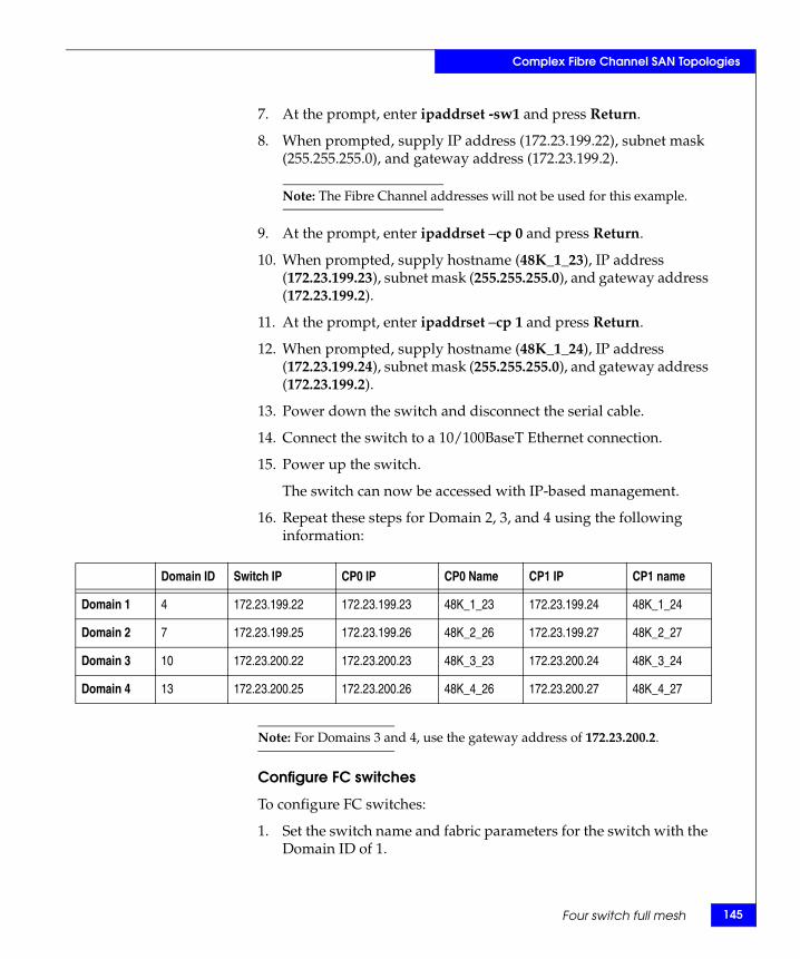
Complex Fibre Channel SAN Topologies
7. At the prompt, enter ipaddrset -sw1 and press Return.
8. When prompted, supply IP address (172.23.199.22), subnet mask (255.255.255.0), and gateway address (172.23.199.2).
Note: The Fibre Channel addresses will not be used for this example.
9. At the prompt, enter ipaddrset –cp 0 and press Return.
10. When prompted, supply hostname (48K_1_23), IP address (172.23.199.23), subnet mask (255.255.255.0), and gateway address (172.23.199.2).
11. At the prompt, enter ipaddrset –cp 1 and press Return.
12. When prompted, supply hostname (48K_1_24), IP address (172.23.199.24), subnet mask (255.255.255.0), and gateway address (172.23.199.2).
13. Power down the switch and disconnect the serial cable.
14. Connect the switch to a 10/100BaseT Ethernet connection.
15. Power up the switch.
The switch can now be accessed with IP-based management.
16. Repeat these steps for Domain 2, 3, and 4 using the following information:
Note: For Domains 3 and 4, use the gateway address of 172.23.200.2.
Configure FC switches
To configure FC switches:
1. Set the switch name and fabric parameters for the switch with the Domain ID of 1.
Domain ID Switch IP CP0 IP CP0 Name CP1 IP CP1 name
Domain 1 4 172.23.199.22 172.23.199.23 48K_1_23 172.23.199.24 48K_1_24
Domain 2 7 172.23.199.25 172.23.199.26 48K_2_26 172.23.199.27 48K_2_27
Domain 3 10 172.23.200.22 172.23.200.23 48K_3_23 172.23.200.24 48K_3_24
Domain 4 13 172.23.200.25 172.23.200.26 48K_4_26 172.23.200.27 48K_4_27
Four switch full mesh 145
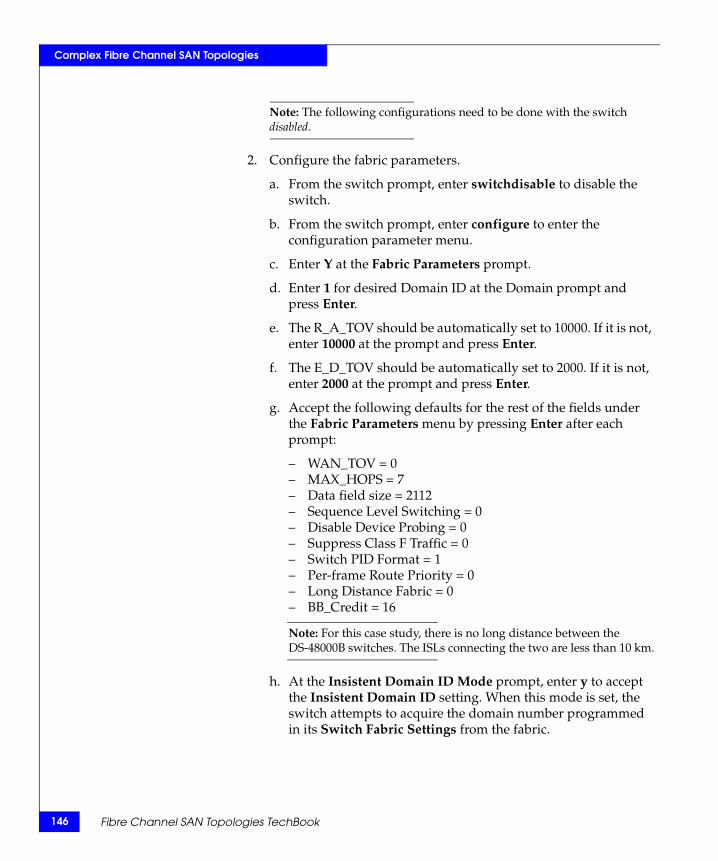
146
Complex Fibre Channel SAN Topologies
Note: The following configurations need to be done with the switch disabled.
2. Configure the fabric parameters.
a. From the switch prompt, enter switchdisable to disable the switch.
b. From the switch prompt, enter configure to enter the configuration parameter menu.
c. Enter Y at the Fabric Parameters prompt.
d. Enter 1 for desired Domain ID at the Domain prompt and press Enter.
e. The R_A_TOV should be automatically set to 10000. If it is not, enter 10000 at the prompt and press Enter.
f. The E_D_TOV should be automatically set to 2000. If it is not, enter 2000 at the prompt and press Enter.
g. Accept the following defaults for the rest of the fields under the Fabric Parameters menu by pressing Enter after each prompt:
– WAN_TOV = 0– MAX_HOPS = 7– Data field size = 2112– Sequence Level Switching = 0– Disable Device Probing = 0– Suppress Class F Traffic = 0– Switch PID Format = 1– Per-frame Route Priority = 0– Long Distance Fabric = 0– BB_Credit = 16
Note: For this case study, there is no long distance between the DS-48000B switches. The ISLs connecting the two are less than 10 km.
h. At the Insistent Domain ID Mode prompt, enter y to accept the Insistent Domain ID setting. When this mode is set, the switch attempts to acquire the domain number programmed in its Switch Fabric Settings from the fabric.
Fibre Channel SAN Topologies TechBook

Complex Fibre Channel SAN Topologies
i. Accept the default values from the remaining Fabric Parameter Menu items by pressing Enter after each prompt:
– Virtual Channel parameters (yes, y, no, n): [no]– F_Port login parameters (yes, y, no, n): [no]– Zoning Operation parameters (yes, y, no, n): [no]– RSCN Transmission Mode (yes, y, no, n): [no]– Arbitrated Loop parameters (yes, y, no, n): [no]– System services (yes, y, no, n): [no]– Portlog events enable (yes, y, no, n): [no]– ssl attributes (yes, y, no, n): [no]– http attributes (yes, y, no, n): [no]– snmp attributes (yes, y, no, n): [no]– rpcd attributes (yes, y, no, n): [no]– cfgload attributes (yes, y, no, n): [no]– web tools attributes (yes, y, no, n): [no]
Note: You may also press CNTRL D after making the last change in the menu to exit and save the changes. This will eliminate the need to accept the default values for the rest of the menu items.
j. Repeat from Step a for switches with the Domain IDs 2, 3, and 4.
Connect cables
To connect the cables:
1. Connect ISLs.
a. Attach Fiber cable between switches as shown in Figure 17 on page 141.
b. After all cables are connected, use switchshow and topologyshow commands to ensure all links.
2. Connect host and storage ports.
a. Attach fiber cable between switches and N_Ports.
3. Verify port login status.
a. After all cables are connected, use the switchshow CLI command to verify the all of the ports logged into the switch.
Four switch full mesh 147
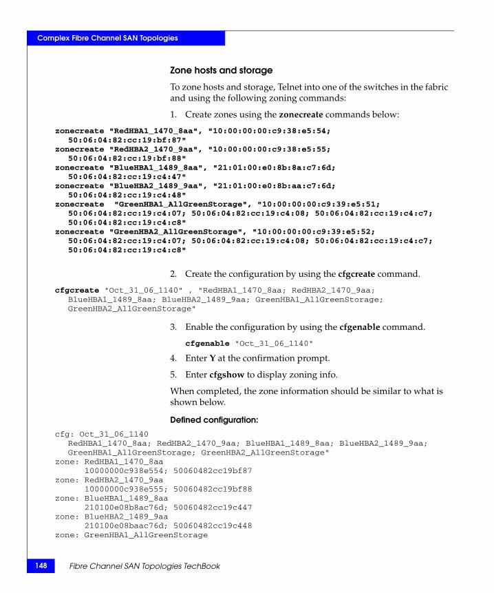
148
Complex Fibre Channel SAN Topologies
Zone hosts and storage
To zone hosts and storage, Telnet into one of the switches in the fabric and using the following zoning commands:
1. Create zones using the zonecreate commands below:
zonecreate "RedHBA1_1470_8aa", "10:00:00:00:c9:38:e5:54; 50:06:04:82:cc:19:bf:87"
zonecreate "RedHBA2_1470_9aa", "10:00:00:00:c9:38:e5:55; 50:06:04:82:cc:19:bf:88"
zonecreate "BlueHBA1_1489_8aa", "21:01:00:e0:8b:8a:c7:6d; 50:06:04:82:cc:19:c4:47"
zonecreate "BlueHBA2_1489_9aa", "21:01:00:e0:8b:aa:c7:6d; 50:06:04:82:cc:19:c4:48"
zonecreate "GreenHBA1_AllGreenStorage", "10:00:00:00:c9:39:e5:51; 50:06:04:82:cc:19:c4:07; 50:06:04:82:cc:19:c4:08; 50:06:04:82:cc:19:c4:c7; 50:06:04:82:cc:19:c4:c8"
zonecreate "GreenHBA2_AllGreenStorage", "10:00:00:00:c9:39:e5:52; 50:06:04:82:cc:19:c4:07; 50:06:04:82:cc:19:c4:08; 50:06:04:82:cc:19:c4:c7; 50:06:04:82:cc:19:c4:c8"
2. Create the configuration by using the cfgcreate command.
cfgcreate "Oct_31_06_1140" , "RedHBA1_1470_8aa; RedHBA2_1470_9aa; BlueHBA1_1489_8aa; BlueHBA2_1489_9aa; GreenHBA1_AllGreenStorage; GreenHBA2_AllGreenStorage"
3. Enable the configuration by using the cfgenable command.
cfgenable "Oct_31_06_1140"
4. Enter Y at the confirmation prompt.
5. Enter cfgshow to display zoning info.
When completed, the zone information should be similar to what is shown below.
Defined configuration:
cfg: Oct_31_06_1140RedHBA1_1470_8aa; RedHBA2_1470_9aa; BlueHBA1_1489_8aa; BlueHBA2_1489_9aa; GreenHBA1_AllGreenStorage; GreenHBA2_AllGreenStorage"
zone: RedHBA1_1470_8aa10000000c938e554; 50060482cc19bf87
zone: RedHBA2_1470_9aa10000000c938e555; 50060482cc19bf88
zone: BlueHBA1_1489_8aa210100e08b8ac76d; 50060482cc19c447
zone: BlueHBA2_1489_9aa210100e08baac76d; 50060482cc19c448
zone: GreenHBA1_AllGreenStorage
Fibre Channel SAN Topologies TechBook
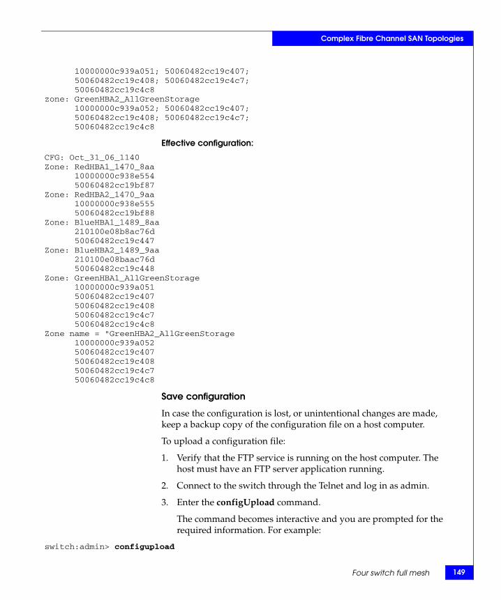
Complex Fibre Channel SAN Topologies
10000000c939a051; 50060482cc19c407;50060482cc19c408; 50060482cc19c4c7;50060482cc19c4c8
zone: GreenHBA2_AllGreenStorage10000000c939a052; 50060482cc19c407;50060482cc19c408; 50060482cc19c4c7;50060482cc19c4c8
Effective configuration:
CFG: Oct_31_06_1140Zone: RedHBA1_1470_8aa
10000000c938e55450060482cc19bf87
Zone: RedHBA2_1470_9aa10000000c938e55550060482cc19bf88
Zone: BlueHBA1_1489_8aa210100e08b8ac76d50060482cc19c447
Zone: BlueHBA2_1489_9aa210100e08baac76d50060482cc19c448
Zone: GreenHBA1_AllGreenStorage10000000c939a05150060482cc19c40750060482cc19c40850060482cc19c4c750060482cc19c4c8
Zone name = "GreenHBA2_AllGreenStorage10000000c939a05250060482cc19c40750060482cc19c40850060482cc19c4c750060482cc19c4c8
Save configuration
In case the configuration is lost, or unintentional changes are made, keep a backup copy of the configuration file on a host computer.
To upload a configuration file:
1. Verify that the FTP service is running on the host computer. The host must have an FTP server application running.
2. Connect to the switch through the Telnet and log in as admin.
3. Enter the configUpload command.
The command becomes interactive and you are prompted for the required information. For example:
switch:admin> configupload
Four switch full mesh 149
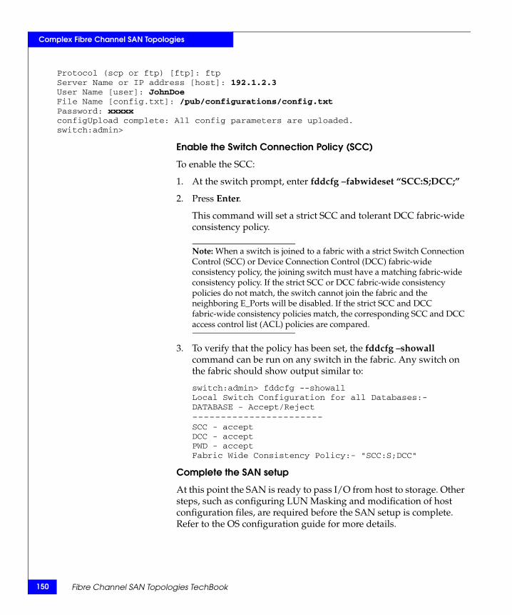
150
Complex Fibre Channel SAN Topologies
Protocol (scp or ftp) [ftp]: ftpServer Name or IP address [host]: 192.1.2.3User Name [user]: JohnDoeFile Name [config.txt]: /pub/configurations/config.txtPassword: xxxxxconfigUpload complete: All config parameters are uploaded.switch:admin>
Enable the Switch Connection Policy (SCC)
To enable the SCC:
1. At the switch prompt, enter fddcfg –fabwideset “SCC:S;DCC;”
2. Press Enter.
This command will set a strict SCC and tolerant DCC fabric-wide consistency policy.
Note: When a switch is joined to a fabric with a strict Switch Connection Control (SCC) or Device Connection Control (DCC) fabric-wide consistency policy, the joining switch must have a matching fabric-wide consistency policy. If the strict SCC or DCC fabric-wide consistency policies do not match, the switch cannot join the fabric and the neighboring E_Ports will be disabled. If the strict SCC and DCC fabric-wide consistency policies match, the corresponding SCC and DCC access control list (ACL) policies are compared.
3. To verify that the policy has been set, the fddcfg –showall command can be run on any switch in the fabric. Any switch on the fabric should show output similar to:
switch:admin> fddcfg --showallLocal Switch Configuration for all Databases:-DATABASE - Accept/Reject-----------------------SCC - acceptDCC - acceptPWD - acceptFabric Wide Consistency Policy:- "SCC:S;DCC"
Complete the SAN setup
At this point the SAN is ready to pass I/O from host to storage. Other steps, such as configuring LUN Masking and modification of host configuration files, are required before the SAN setup is complete. Refer to the OS configuration guide for more details.
Fibre Channel SAN Topologies TechBook
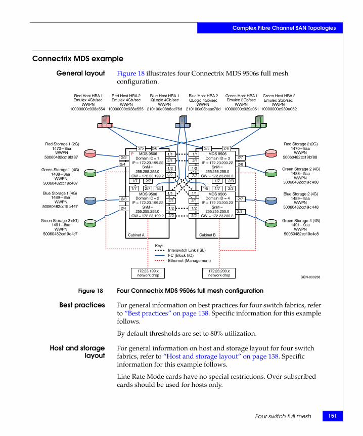
Complex Fibre Channel SAN Topologies
Connectrix MDS example
General layout Figure 18 illustrates four Connectrix MDS 9506s full mesh configuration.
Figure 18 Four Connectrix MDS 9506s full mesh configuration
Best practices For general information on best practices for four switch fabrics, refer to “Best practices” on page 138. Specific information for this example follows.
By default thresholds are set to 80% utilization.
Host and storagelayout
For general information on host and storage layout for four switch fabrics, refer to “Host and storage layout” on page 138. Specific information for this example follows.
Line Rate Mode cards have no special restrictions. Over-subscribed cards should be used for hosts only.
GEN-000238
Key:
Domain ID = 1 IP = 172 . 23 . 199 . 22
SnM = 255 . 255 . 255 . 0
GW = 172 . 23 . 199 . 2
Domain ID = 2 IP = 172 . 23 . 199 . 23
SnM = 255 . 255 . 255 . 0
GW = 172 . 23 . 199 . 2
Domain ID = 4IP = 172 . 23 . 200 . 23
SnM = 255 . 255 . 255 . 0
GW = 172 . 23 . 200 . 2
Domain ID = 3IP = 172 . 23 . 200 . 22
SnM = 255 . 255 . 255 . 0
GW = 172 . 23 . 200 . 2
172.23.199.x network drop
Cabinet A Cabinet B
172 . 23 . 200 . x network drop
Red Host HBA 1 Emulex 4 Gb / sec
WWPN 10000000 c 938 e 554
Red Host HBA 2 Emulex 4 Gb / sec
WWPN 10000000 c 938 e 555
Green Host HBA 1 Emulex 2 Gb / sec
WWPN 10000000 c 939 a 051
Green Host HBA 2 Emulex 2 Gb / sec
WWPN 10000000 c 939 a 052
Blue Host HBA 1QLogic 4 Gb / sec
WWPN 210100 e 08 b 8 ac 76 d
Blue Host HBA 2 QLogic 4 Gb / sec
WWPN 210100 e 08 baac 76 d
Red Storage 2 ( 2 G ) 1470 – 9 aa
WWPN 50060482 cc 19 bf 88
Red Storage 1 (2G)1470 – 8 aa
WWPN 50060482 cc 19 bf 87
Green Storage 1 ( 4 G ) 1488 – 8 aa
WWPN 50060482 cc 19 c 407
Green Storage 2 ( 4 G ) 1488 – 9 aa
WWPN 50060482 cc 19 c 408
Blue Storage 1 ( 4 G ) 1489 – 8 aa
WWPN 50060482 cc 19 c 447
Blue Storage 2 ( 4 G ) 1489 – 9 aa
WWPN 50060482 cc 19 c 448
Green Storage 3 ( 4 G ) 1491 – 8 aa
WWPN 50060482 cc 19 c 4 c 7
Green Storage 4 ( 4 G ) 1491 – 9 aa
WWPN 50060482 cc 19 c 4 c 8
2/5 2/5
1/1 1/1
2/1 2/1
2/6 2/6
1/7 2/7 1/5 1/5 1/7 2/3
1/7 2/7
1/2
2/2
2/1
1/1
1/2
2/2
1/2
2/2
1/1
2/1
1/2
2/2
2/3
2/4
2/3
2/4
1/7 2/3
2/7
2/8
2/7
2/8
Interswitch Link (ISL) FC (Block I/O) Ethernet (Management)
P MDS 9506
MDS 9506
MDS 9506
MDS 9506
Four switch full mesh 151
152
Complex Fibre Channel SAN Topologies
Switch and fabricmanagement
For general information on host and storage layout for four switch fabrics, refer to “Switch and fabric management” on page 138. Specific information for this example follows.
For this topology Fabric Manager can be used.
Security For general information on security, for four switch fabrics, refer to “Security” on page 138. Specific information for this example follows.
Use switch and Port Binding for security.
Setting up thistopology
Assumptions specific to this case study:
◆ The switches are installed in an EMC-supplied cabinet.
• For installation instructions, see Connectrix EC-1500 Cabinet Installation and Setup Manual, which can be accessed from Powerlink.
◆ The proper power receptacles have been provided by the customer.
• For switch power requirements, refer to the EMC Connectrix SAN Products Data Reference Manual, available through the E-Lab Interoperability Navigator, Topology Resource Center tab, at http://elabnavigator.EMC.com.
• For Cabinet power requirements, refer to Connectrix EC-1500 Cabinet Installation and Setup Manual, which can be accessed from Powerlink.
◆ The switches have not been connected to the power source and are not powered on.
◆ Network drops, IP addresses, subnet mask, and gateway have been provided by the customer.
For switch or cabinet network requirements, refer to the EMC Connectrix SAN Products Data Reference Manual, available through the E-Lab Interoperability Navigator, Topology Resource Center tab, at http://elabnavigator.EMC.com.
Fibre Channel SAN Topologies TechBook
Complex Fibre Channel SAN Topologies
Note: Connectrix MDS switches can be directly connected to the customer’s LAN. The switches can be placed on either a public or private network. There are advantages to both configurations. For more information, refer to "Public versus private" in the Networked Storage Concepts and Protocols TechBook, available through the E-Lab Interoperability Navigator, Topology Resource Center tab, at http://elabnavigator.EMC.com.
This example assumes that the customer has provided us with two Ethernet cables and that one of them is on the 172.23.199.x network and that the other is connected to the 172.23.200.x network.
◆ The proper number of line cards have been installed into the Connectrix MDS 9513s.
• For help in determining how many ports are required, refer to "Determining customer requirements" in the Networked Storage Concepts and Protocols TechBook, available through the E-Lab Interoperability Navigator, Topology Resource Center tab, at http://elabnavigator.EMC.com.
◆ License keys have been obtained.
• Go to the URL listed on the transaction code certificate that shipped with the product to get the license key.
◆ A laptop, connected to a Connectrix MDS serial port, will be used to configure the IP addresses of the switches.
◆ The customer has provided a temporary password that will be used as the default password when configuring the IP address.
◆ Cisco CLI, Fabric Manager, and Device Manager will be used.
Configure the IP address
To configure the IP address:
1. Power up the cabinet by connecting the power cords to the power receptacles provided by the customer.
2. Select one of the switches to configure and set the IP to 172.23.199.22.
3. Supply a network connection to the appropriate subnet.
4. Using an RS232 serial cable, connect to the serial port of the switch with a baud rate of 9600, 8 data bits, no parity, 1 stop bit and no flow control.
Four switch full mesh 153
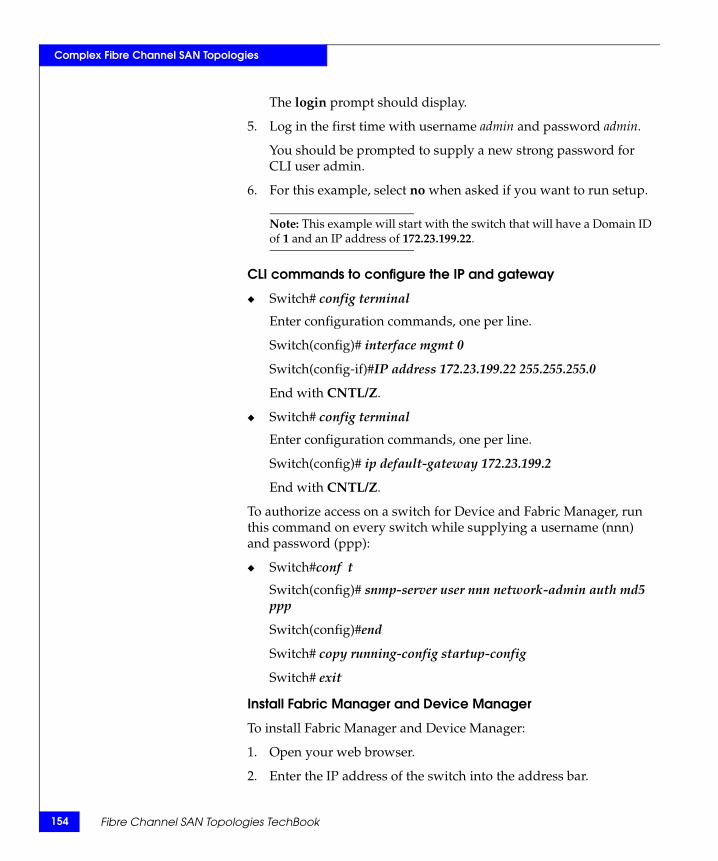
154
Complex Fibre Channel SAN Topologies
The login prompt should display.
5. Log in the first time with username admin and password admin.
You should be prompted to supply a new strong password for CLI user admin.
6. For this example, select no when asked if you want to run setup.
Note: This example will start with the switch that will have a Domain ID of 1 and an IP address of 172.23.199.22.
CLI commands to configure the IP and gateway
◆ Switch# config terminal
Enter configuration commands, one per line.
Switch(config)# interface mgmt 0
Switch(config-if)#IP address 172.23.199.22 255.255.255.0
End with CNTL/Z.
◆ Switch# config terminal
Enter configuration commands, one per line.
Switch(config)# ip default-gateway 172.23.199.2
End with CNTL/Z.
To authorize access on a switch for Device and Fabric Manager, run this command on every switch while supplying a username (nnn) and password (ppp):
◆ Switch#conf t
Switch(config)# snmp-server user nnn network-admin auth md5 ppp
Switch(config)#end
Switch# copy running-config startup-config
Switch# exit
Install Fabric Manager and Device Manager
To install Fabric Manager and Device Manager:
1. Open your web browser.
2. Enter the IP address of the switch into the address bar.
Fibre Channel SAN Topologies TechBook

Complex Fibre Channel SAN Topologies
3. Follow the prompts and accept all defaults to install both Fabric Manager and Device Manager.
Fabric Manager and Device Manager can be started using the configured snmp-server username and password in “CLI commands to configure the IP and gateway” on page 154.
Configure a VSAN
To configure a VSAN:
1. Open the Device Manager for the switch with an IP address of 172.23.199.22.
2. Open the VSAN dialog box by selecting the VSAN menu item.
3. Click Create.
4. Enter the value of 100 into the VSAN ID field.
5. Set the VSAN Name to be “Red_VSAN_100”.
6. Use the default interop mode.
7. Click Create.
Configure the other VSANs in this physical switch
To configure the other VSANs:
1. Repeat Step 2 through Step 7 above, in “Configure a VSAN,” for VSAN 200 and VSAN 300 nothing that:
a. For virtual switch 200, use VSAN Name “Green_VSAN_200”.
b. For virtual switch 300, use VSAN Name “Blue_VSAN_300”.
2. Assign and enable the ports to the proper VSAN using Device Manager for the switch.
a. Following Step 1 and Step 2, configure the ports of the switch with an IP address of 172.23.199.22 as shown in the tables below.
Slot # Port # Name VSAN ID
1 1 TE ISL to SW 3 1
1 2 TE ISL to SW 4 1
1 3
1 4
1 5
Four switch full mesh 155
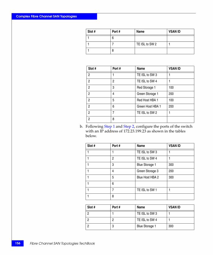
156
Complex Fibre Channel SAN Topologies
b. Following Step 1 and Step 2, configure the ports of the switch with an IP address of 172.23.199.23 as shown in the tables below.
1 6
1 7 TE ISL to SW 2 1
1 8
Slot # Port # Name VSAN ID
2 1 TE ISL to SW 3 1
2 2 TE ISL to SW 4 1
2 3 Red Storage 1 100
2 4 Green Storage 1 200
2 5 Red Host HBA 1 100
2 6 Green Host HBA 1 200
2 7 TE ISL to SW 2 1
2 8
Slot # Port # Name VSAN ID
1 1 TE ISL to SW 3 1
1 2 TE ISL to SW 4 1
1 3 Blue Storage 1 300
1 4 Green Storage 3 200
1 5 Blue Host HBA 2 300
1 6
1 7 TE ISL to SW 1 1
1 8
Slot # Port # Name VSAN ID
2 1 TE ISL to SW 3 1
2 2 TE ISL to SW 4 1
2 3 Blue Storage 1 300
Slot # Port # Name VSAN ID
Fibre Channel SAN Topologies TechBook
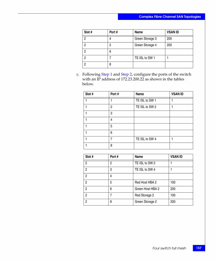
Complex Fibre Channel SAN Topologies
c. Following Step 1 and Step 2, configure the ports of the switch with an IP address of 172.23.200.22 as shown in the tables below.
2 4 Green Storage 3 200
2 5 Green Storage 4 200
2 6
2 7 TE ISL to SW 1 1
2 8
Slot # Port # Name VSAN ID
1 1 TE ISL to SW 1 1
1 2 TE ISL to SW 2 1
1 3
1 4
1 5
1 6
1 7 TE ISL to SW 4 1
1 8
Slot # Port # Name VSAN ID
2 2 TE ISL to SW 2 1
2 3 TE ISL to SW 4 1
2 4
2 5 Red Host HBA 2 100
2 6 Green Host HBA 2 200
2 7 Red Storage 2 100
2 8 Green Storage 2 200
Slot # Port # Name VSAN ID
Four switch full mesh 157
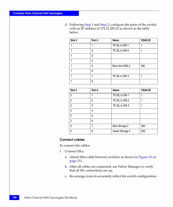
158
Complex Fibre Channel SAN Topologies
d. Following Step 1 and Step 2, configure the ports of the switch with an IP address of 172.23.200.23 as shown in the table below.
Connect cables
To connect the cables:
1. Connect ISLs.
a. Attach fiber cable between switches as shown in Figure 18 on page 151.
b. After all cables are connected, use Fabric Manager to verify that all ISL connections are up.
c. Re-arrange icons to accurately reflect the switch configuration.
Slot # Port # Name VSAN ID
1 1 TE ISL to SW 1 1
1 2 TE ISL to SW 2 1
1 3
1 4
1 5 Blue Host HBA 2 300
1 6
1 7 TE ISL to SW 3 1
1 8
Slot # Port # Name VSAN ID
2 1 TE ISL to SW 1 1
2 2 TE ISL to SW 2 1
2 3 TE ISL to SW 3 1
2 4
2 5
2 6
2 7 Blue Storage 2 300
2 8 Green Storage 4 200
Fibre Channel SAN Topologies TechBook

Complex Fibre Channel SAN Topologies
Note: When looking at the topology view after persisting the fabric, you can immediately detect if something has changed in the environment. For example, if an ISL or device disappeared, yellow alert icons display. Because of this feature, it is recommended to always persist the fabric after changes have been made.
2. Connect host and storage ports.
a. Attach fibre cable between the switches and N_Ports.
Zone hosts and storage
To zone hosts and storage:
1. Open the Zoning menu in Fabric Manager for the desired VSAN.
2. Create a zone by clicking New Zone under Zones.
3. Provide a descriptive name for the zone. This example will zone “Red host HBA 1” and “Red Storage 1”. Type “RedHBA1_1470_8aa” and press Enter.
4. In zone "RedHBA1_1470_8aa" select (WWPN 10000000c938e554) select add to zone.
5. Select “Red Storage 1” (WWPN 50060482cc19bf87) in the potential zone members list.
6. Create the VSAN zoneset, add the zones, then activate the zoneset.
7. Repeat Step 2 through Step 6 for all host and storage pairs in the environment.
.Zone set name = "VSAN Red 100"
Zone name = "RedHBA1_1470_8aa"Zone Member = "10000000c938e554"Zone Member = "50060482cc19bf87"
Zone name = "RedHBA2_1470_9aa"Zone Member = "10000000c938e555"Zone Member = "50060482cc19bf88"
Zone set name = "VSAN Green 200"
Zone name = "GreenHBA1_1489_8aa"Zone Member = "210100e08b8ac76d"Zone Member = "50060482cc19c447"
Four switch full mesh 159
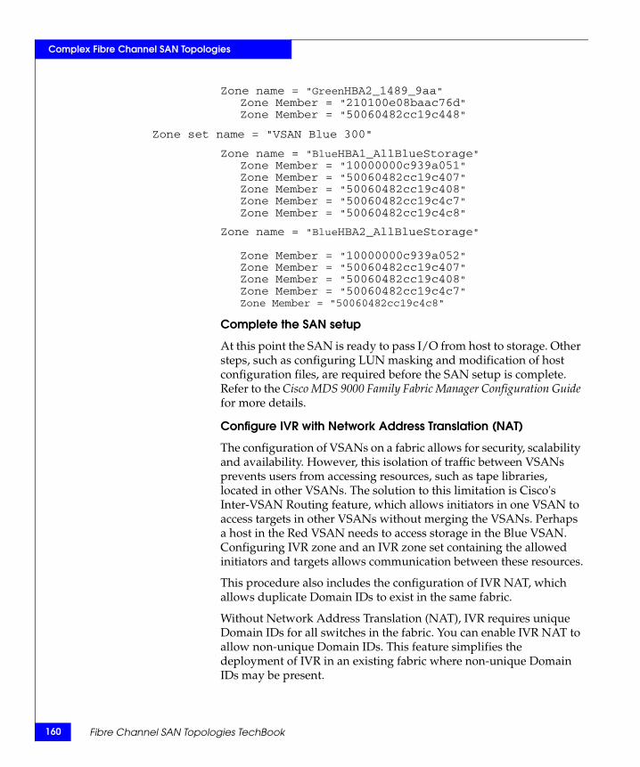
160
Complex Fibre Channel SAN Topologies
Zone name = "GreenHBA2_1489_9aa"Zone Member = "210100e08baac76d"Zone Member = "50060482cc19c448"
Zone set name = "VSAN Blue 300"
Zone name = "BlueHBA1_AllBlueStorage"Zone Member = "10000000c939a051"Zone Member = "50060482cc19c407"Zone Member = "50060482cc19c408"Zone Member = "50060482cc19c4c7"Zone Member = "50060482cc19c4c8"
Zone name = "BlueHBA2_AllBlueStorage"
Zone Member = "10000000c939a052"Zone Member = "50060482cc19c407"Zone Member = "50060482cc19c408"Zone Member = "50060482cc19c4c7"Zone Member = "50060482cc19c4c8"
Complete the SAN setup
At this point the SAN is ready to pass I/O from host to storage. Other steps, such as configuring LUN masking and modification of host configuration files, are required before the SAN setup is complete. Refer to the Cisco MDS 9000 Family Fabric Manager Configuration Guide for more details.
Configure IVR with Network Address Translation (NAT)
The configuration of VSANs on a fabric allows for security, scalability and availability. However, this isolation of traffic between VSANs prevents users from accessing resources, such as tape libraries, located in other VSANs. The solution to this limitation is Cisco's Inter-VSAN Routing feature, which allows initiators in one VSAN to access targets in other VSANs without merging the VSANs. Perhaps a host in the Red VSAN needs to access storage in the Blue VSAN. Configuring IVR zone and an IVR zone set containing the allowed initiators and targets allows communication between these resources.
This procedure also includes the configuration of IVR NAT, which allows duplicate Domain IDs to exist in the same fabric.
Without Network Address Translation (NAT), IVR requires unique Domain IDs for all switches in the fabric. You can enable IVR NAT to allow non-unique Domain IDs. This feature simplifies the deployment of IVR in an existing fabric where non-unique Domain IDs may be present.
Fibre Channel SAN Topologies TechBook

Complex Fibre Channel SAN Topologies
Note: To use IVR NAT, it must be enabled in all IVR-enabled switches in the fabric IVR configuration distribution. By default, IVR NAT and IVR configuration distribution are disabled in all switches fin the Cisco MDS 9000 Family.
1. In Fabric Manager:
a. Click the Zone tab in upper tool bar.
b. Click the IVR tab.
c. Select Wizard.
To migrate to IVR NAT mode click Yes; otherwise click No. You see the IVR Zone Wizard.
Note: If you are not using IVR NAT, Fabric Manager may display an error message if all the switches participating in IVR do not have unique Domain IDs. You must reconfigure those switches before configuring IVR.
2. Select the VSANs that will participate in IVR in the fabric.
Select VSAN 100, 200 and 300.
3. Select the end devices that you want to communicate over IVR.
Select the following:
VSAN 100: 10000000c938e554
VSAN 200: 50060482cc19c407
VSAN300: 50060482cc19c447
VSAN 300: 210100e08b8ac76d
4. Enter the VSAN ID of the VSAN you want to use as the transit VSAN between the VSANs selected for the IVR zone.
Select VSAN 1 as the transit VSAN.
Note: VSAN 1 connects both switches and all trunking traffic will pass over this link to communicate with VSANs in other switches.
5. Set the IVR zone and IVR zone set.
IVR NAME = IVRZONE1
IVR ZONENET NAME = IVRZONESET1
Four switch full mesh 161
162
Complex Fibre Channel SAN Topologies
6. Verify all steps that Fabric Manager will take to configure IVR in the fabric.
7. Click Finish if you want to enable IVR NAT and IVR topology and to create the associated IVR zones and IVR zone set.
or
Click Cancel to exit the IVR Wizard without saving any changes.
8. The Save Configuration dialog box displays. You can save the configuration of the master witch to be copied to other IVR-enabled switches.
Click either Continue Activation or Cancel.
9. Click Finish.
Fibre Channel SAN Topologies TechBook
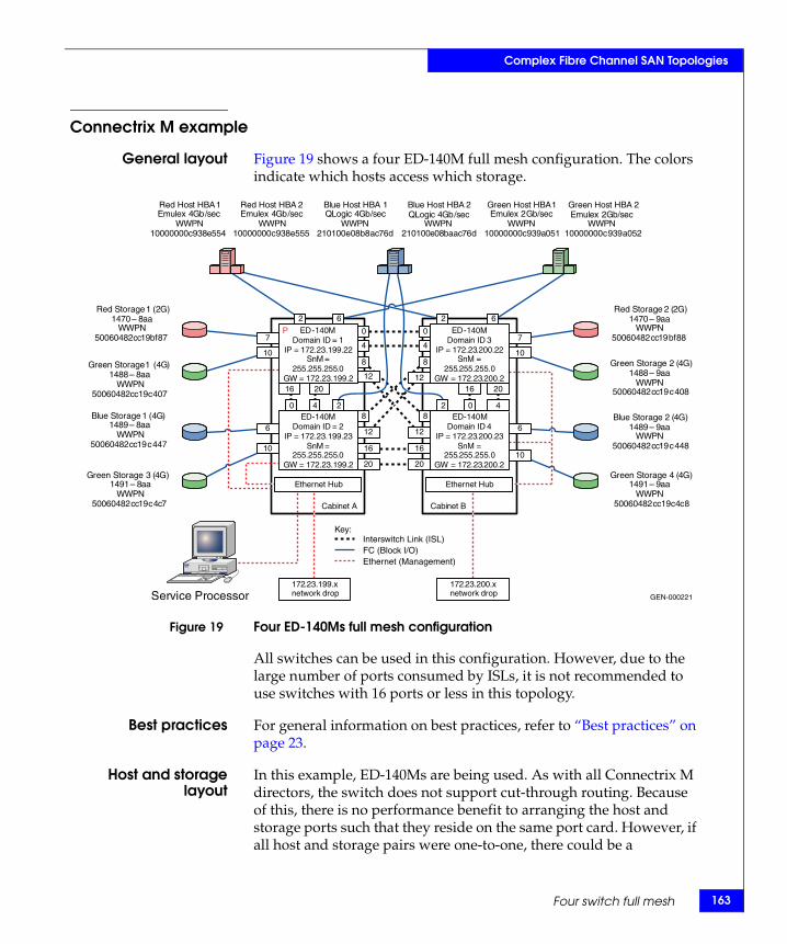
Complex Fibre Channel SAN Topologies
Connectrix M example
General layout Figure 19 shows a four ED-140M full mesh configuration. The colors indicate which hosts access which storage.
Figure 19 Four ED-140Ms full mesh configuration
All switches can be used in this configuration. However, due to the large number of ports consumed by ISLs, it is not recommended to use switches with 16 ports or less in this topology.
Best practices For general information on best practices, refer to “Best practices” on page 23.
Host and storagelayout
In this example, ED-140Ms are being used. As with all Connectrix M directors, the switch does not support cut-through routing. Because of this, there is no performance benefit to arranging the host and storage ports such that they reside on the same port card. However, if all host and storage pairs were one-to-one, there could be a
GEN-000221
Key:
ED - 140 M Domain ID = 1
IP = 172 . 23 . 199 . 22 SnM =
255 . 255 . 255 . 0 GW = 172 . 23 . 199 . 2
ED - 140 M Domain ID = 2
IP = 172 . 23 . 199 . 23 SnM =
255 . 255 . 255 . 0 GW = 172 . 23 . 199 . 2
ED - 140 M Domain ID 4
IP = 172 . 23 . 200 . 23 SnM =
255 . 255 . 255 . 0 GW = 172 . 23 . 200 . 2
ED - 140 M Domain ID 3
IP = 172 . 23 . 200 . 22 SnM =
255 . 255 . 255 . 0 GW = 172 . 23 . 200 . 2
172 . 23 . 199 . x network drop
Cabinet A Cabinet B
Service Processor
Ethernet Hub Ethernet Hub
172 . 23 . 200 . x network drop
Red Host HBA 1 Emulex 4 Gb / sec
WWPN 10000000 c 938 e 554
Red Host HBA 2 Emulex 4 Gb / sec
WWPN 10000000 c 938 e 555
Green Host HBA 1 Emulex 2 Gb / sec
WWPN 10000000 c 939 a 051
Green Host HBA 2 Emulex 2 Gb / sec
WWPN 10000000 c 939 a 052
Blue Host HBA 1QLogic 4 Gb / sec
WWPN 210100 e 08 b 8 ac 76 d
Blue Host HBA 2 QLogic 4 Gb / sec
WWPN 210100 e 08 baac 76 d
Red Storage 2 ( 2 G ) 1470 – 9 aa
WWPN 50060482 cc 19 bf 88
Red Storage 1 (2G)1470 – 8 aa
WWPN 50060482 cc 19 bf 87
Green Storage 1 ( 4 G ) 1488 – 8 aa
WWPN 50060482 cc 19 c 407
Green Storage 2 ( 4 G ) 1488 – 9 aa
WWPN 50060482 cc 19 c 408
Blue Storage 1 ( 4 G ) 1489 – 8 aa
WWPN 50060482 cc 19 c 447
Blue Storage 2 ( 4 G ) 1489 – 9 aa
WWPN 50060482 cc 19 c 448
Green Storage 3 ( 4 G ) 1491 – 8 aa
WWPN 50060482 cc 19 c 4 c 7
Green Storage 4 ( 4 G ) 1491 – 9 aa
WWPN 50060482 cc 19 c 4 c 8
2 2
0 0
4 4
6 6
0 4 2 2 0 4
16 20
16
20
12
8
8
12
8
12
8
12
16
20
7
10
6
10
16 20
7
10
6
10
Interswitch Link (ISL) FC (Block I/O) Ethernet (Management)
P
Four switch full mesh 163
164
Complex Fibre Channel SAN Topologies
serviceability benefit realized from this arrangement. This is due to the fact that if it is arranged this way and a port card needed to be replaced, only two host and storage pairs would be impacted, whereas if each port card has connections from a different host and storage pair, up to four pairs could be impacted. This point is raised only for the purposes of having the reader consider their particular situation to see if there are serviceability benefits from a particular arrangement, even if there may be no performance benefits realized.
For general information on host and storage layout, refer to “Host and storage layout” on page 30.
Switch and fabricmanagement
CLI, Connectrix Manager Basic, and Connectrix Manager can all be used to set up this configuration. In this example, Connectrix Manager will be used. For general information on switch and fabric management, refer to “Switch and fabric management” on page 32.
Security For general information on security, refer to “Security” on page 36.
Setting up thistopology
Assumptions specific to this case study:
◆ The switches are installed in an EMC-supplied cabinet.
• For installation instructions, see Connectrix EC-1500 Cabinet Installation and Setup Manual, which can be accessed from Powerlink.
◆ The proper power receptacles have been provided by the customer.
• For switch power requirements, refer to the EMC Connectrix SAN Products Data Reference Manual, available through the E-Lab Interoperability Navigator, Topology Resource Center tab, at http://elabnavigator.EMC.com.
• For cabinet power requirements, refer to Connectrix EC-1500 Cabinet Installation and Setup Manual, which can be accessed from Powerlink.
◆ The switches have not been connected to the power source and are not powered on.
Note: Connectrix M switches ship with a default IP address of 10.1.1.10. If all of the switches are powered on and connected to the hub in the switch cabinet, communication with the switch using the network interfaces will not be possible and you will have to program the IP addresses using the serial port.
Fibre Channel SAN Topologies TechBook
Complex Fibre Channel SAN Topologies
This section assumes that the serial port will not be used and the IP addresses will be programmed through the network interface.
◆ Network drops, IP addresses, subnet mask, and gateway have been provided by the customer.
• For switch or cabinet network requirements, refer to refer to the EMC Connectrix SAN Products Data Reference Manual, available through the E-Lab Interoperability Navigator, Topology Resource Center tab, at http://elabnavigator.EMC.com.
Note: Connectrix M switches can be either attached to the Ethernet hub that comes with the cabinet, or directly connected to the customer’s LAN. In both cases, the switches can be placed on either a public or private network. There are advantages to both configurations. For more information, refer to "Public versus private" in the Networked Storage Concepts and Protocols TechBook, available through the E-Lab Interoperability Navigator, Topology Resource Center tab, at http://elabnavigator.EMC.com.
This example assumes that the customer has provided us with two Ethernet cables and that one of them is on the 172.23.199.x network and that the other is connected to the 172.23.200.x network.
◆ The proper number of port cards have been installed into the ED-140Ms.
• For help in determining how many ports are required, refer to "Determining customer requirements" in the Networked Storage Concepts and Protocols TechBook, available through the E-Lab Interoperability Navigator, Topology Resource Center tab, at http://elabnavigator.EMC.com.
◆ License keys have been obtained.
• Go to the URL listed on the transaction code certificate that shipped with the product to get the license key.
◆ A Service Processor is installed in at least one of the cabinets.
◆ The Service Processor will be used to configure the IP addresses of the switches.
◆ One interface from the Service Processor is connected to the Ethernet hub and this interface has an IP address of 10.1.1.11. (Check Default on the SP image and use that value.)
Four switch full mesh 165
166
Complex Fibre Channel SAN Topologies
◆ The customer has provided a temporary password that will be used as the default password when configuring the IP address.
◆ Connectrix Manager will be used and the Connectrix Manager installation kit is available.
◆ Connectrix Manager is not already installed on the Service Processor.
Configure the IP address
To configure the IP address:
1. In the cabinet that contains the Service Processor, select one of the switches to configure.
Note: This example will start with the switch that will have a Domain ID of 1 and an IP address of 172.23.199.22.
2. Disconnect the network cables from the other switches in the cabinet.
CAUTION!Failure to do so will cause an IP address conflict when the cabinet is powered up.
Note: The other cabinet should not be powered up yet, but if it is and a network cable is connected between the two hubs, the network cables from the other switches must be disconnected as well to avoid running into duplicate IP address types of problems.
3. Power up the cabinet by connecting the power cords to the power receptacles provided by the customer. This will cause both the Directors and the Service Processor to power up.
4. Log in to the Service Processor once it has powered up. The default username and password is administrator and password.
5. Open a command prompt and ping the IP address of 10.1.1.10. If you get a response, continue to Step 6. If you do not get a response, you can either IML the switch by pushing the little gray button on the CTP or configure the IP address using the serial port.
Fibre Channel SAN Topologies TechBook
Complex Fibre Channel SAN Topologies
Note: See the installation and service manuals for more information about configuring the IP address using the serial port.
6. Launch Internet Explorer and type the IP address of 10.1.1.10 into the address bar and press Enter. The Login banner will be displayed.
7. Click Accept and the Login dialog box will be displayed.
8. Enter the default username and password of Administrator and password, then press Enter.
IMPORTANT!It is strongly recommended that when prompted to change the password, you change it to a password that was provided by the customer.
9. Click Details underneath the switch icon in the Connectrix Manager Basic Topology view.
10. Navigate to the Network Configuration dialog box by clicking the Configure pull-down menu and selecting switch, then Network.
11. Enter the IP address (172.23.199.22), subnet mask (255.255.255.0), and gateway (172.23.199.2), and then click OK.
Note: The error message unable to display appears. This appears because the IP address of the switch has just changed and you are no longer able to connect to the switch at its old IP address.
Configure the rest of the switch IP addresses in the cabinet
To configure the next switch in the cabinet, reconnect the network cables to the CTPs and then follow Step 5 through Step 11 in the previous “Configure the IP address” section. Use the IP address of (172.23.199.23), subnet mask (255.255.255.0), and gateway (172.23.199.2).
Configure the IP addresses of the switches in the other cabinet
To configure the switch in the other cabinet, a cable can be connected between the two hubs to allow for communication between the service processor in one cabinet (cabinet A in our example) and the
Four switch full mesh 167
168
Complex Fibre Channel SAN Topologies
switches in the other cabinet (cabinet B in our example). This technique will be used in this section.
1. Connect a straight through cable to port 24 on the cabinet B. Ensure that MDIX is set on port 24 by pushing the recessed MDI/MDIX button in.
2. Connect the other end of cable connected to port 24 in step 1 to any port other than 24 on the Ethernet hub in cabinet A.
3. Follow Step 5 through Step 11 in the “Configure the IP address” section, which begins on page 166.
a. For the top switch in cabinet B, use the IP address of (172.23.200.22), subnet mask (255.255.255.0), and gateway (172.23.200.2).
b. For the bottom switch in cabinet B, use the IP address of (172.23.200.23), subnet mask (255.255.255.0), and gateway (172.23.200.2).
Install Connectrix Manager
Note: Refer to the EMC Connectrix Manager User Guide for complete installation instructions.
To install Connectrix Manager:
1. Insert the Connectrix Manager installation CD into the CD-RW drive.
2. Browse to the CD-RW drive in windows explorer.
3. Locate, then double-click, the install.exe file. The installer is displayed. Typically, this file is located under the CtxMgr <version number> folder.
4. Accept all the defaults by clicking next and OK, when appropriate.
5. Click Done when the Installation Complete dialog box appears.
6. Click Next when the Welcome dialog box appears.
7. Accept the EULA terms and then click Next.
8. At the Copy data and Settings dialog box, select No, then Next.
Note: "No" is selected in this step since this section assumes that this is a new installation.
Fibre Channel SAN Topologies TechBook
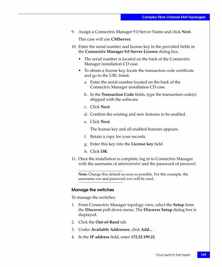
Complex Fibre Channel SAN Topologies
9. Assign a Connectrix Manager 9.0 Server Name and click Next.
This case will use CMServer.
10. Enter the serial number and license key in the provided fields in the Connectrix Manager 9.0 Server License dialog box.
• The serial number is located on the back of the Connectrix Manager installation CD case.
• To obtain a license key, locate the transaction code certificate and go to the URL listed.
a. Enter the serial number located on the back of the Connectrix Manager installation CD case.
b. In the Transaction Code fields, type the transaction code(s) shipped with the software.
c. Click Next.
d. Confirm the existing and new features to be enabled.
e. Click Next.
The license key and all enabled features appears.
f. Retain a copy for your records.
g. Enter this key into the License key field.
h. Click OK.
11. Once the installation is complete, log in to Connectrix Manager with the username of administrator and the password of password.
Note: Change this default as soon as possible. For this example, the username nnn and password nnn will be used.
Manage the switches
To manage the switches:
1. From Connectrix Manager topology view, select the Setup from the Discover pull-down menu. The Discover Setup dialog box is displayed.
2. Click the Out-of-Band tab.
3. Under Available Addresses, click Add... .
4. In the IP address field, enter 172.23.199.22.
Four switch full mesh 169
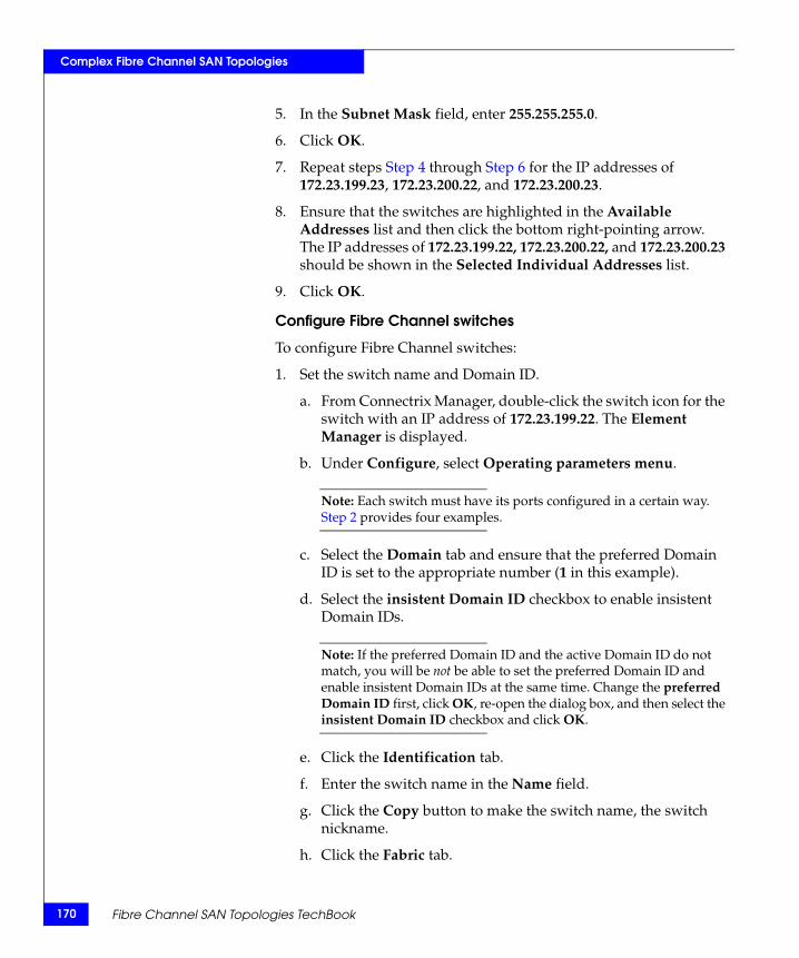
170
Complex Fibre Channel SAN Topologies
5. In the Subnet Mask field, enter 255.255.255.0.
6. Click OK.
7. Repeat steps Step 4 through Step 6 for the IP addresses of 172.23.199.23, 172.23.200.22, and 172.23.200.23.
8. Ensure that the switches are highlighted in the Available Addresses list and then click the bottom right-pointing arrow. The IP addresses of 172.23.199.22, 172.23.200.22, and 172.23.200.23 should be shown in the Selected Individual Addresses list.
9. Click OK.
Configure Fibre Channel switches
To configure Fibre Channel switches:
1. Set the switch name and Domain ID.
a. From Connectrix Manager, double-click the switch icon for the switch with an IP address of 172.23.199.22. The Element Manager is displayed.
b. Under Configure, select Operating parameters menu.
Note: Each switch must have its ports configured in a certain way. Step 2 provides four examples.
c. Select the Domain tab and ensure that the preferred Domain ID is set to the appropriate number (1 in this example).
d. Select the insistent Domain ID checkbox to enable insistent Domain IDs.
Note: If the preferred Domain ID and the active Domain ID do not match, you will be not be able to set the preferred Domain ID and enable insistent Domain IDs at the same time. Change the preferred Domain ID first, click OK, re-open the dialog box, and then select the insistent Domain ID checkbox and click OK.
e. Click the Identification tab.
f. Enter the switch name in the Name field.
g. Click the Copy button to make the switch name, the switch nickname.
h. Click the Fabric tab.
Fibre Channel SAN Topologies TechBook
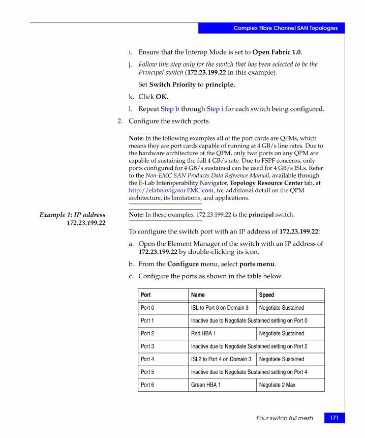
Complex Fibre Channel SAN Topologies
i. Ensure that the Interop Mode is set to Open Fabric 1.0.
j. Follow this step only for the switch that has been selected to be the Principal switch (172.23.199.22 in this example).
Set Switch Priority to principle.
k. Click OK.
l. Repeat Step b through Step i for each switch being configured.
2. Configure the switch ports.
Note: In the following examples all of the port cards are QPMs, which means they are port cards capable of running at 4 GB/s line rates. Due to the hardware architecture of the QPM, only two ports on any QPM are capable of sustaining the full 4 GB/s rate. Due to FSPF concerns, only ports configured for 4 GB/s sustained can be used for 4 GB/s ISLs. Refer to the Non-EMC SAN Products Data Reference Manual, available through the E-Lab Interoperability Navigator, Topology Resource Center tab, at http://elabnavigator.EMC.com, for additional detail on the QPM architecture, its limitations, and applications.
Example 1: IP address172.23.199.22
Note: In these examples, 172.23.199.22 is the principal switch.
To configure the switch port with an IP address of 172.23.199.22:
a. Open the Element Manager of the switch with an IP address of 172.23.199.22 by double-clicking its icon.
b. From the Configure menu, select ports menu.
c. Configure the ports as shown in the table below.
Port Name Speed
Port 0 ISL to Port 0 on Domain 3 Negotiate Sustained
Port 1 Inactive due to Negotiate Sustained setting on Port 0
Port 2 Red HBA 1 Negotiate Sustained
Port 3 Inactive due to Negotiate Sustained setting on Port 2
Port 4 ISL2 to Port 4 on Domain 3 Negotiate Sustained
Port 5 Inactive due to Negotiate Sustained setting on Port 4
Port 6 Green HBA 1 Negotiate 2 Max
Four switch full mesh 171
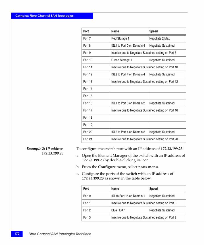
172
Complex Fibre Channel SAN Topologies
Example 2: IP address172.23.199.23
To configure the switch port with an IP address of 172.23.199.23:
a. Open the Element Manager of the switch with an IP address of 172.23.199.23 by double-clicking its icon.
b. From the Configure menu, select ports menu.
c. Configure the ports of the switch with an IP address of 172.23.199.23 as shown in the table below.
Port 7 Red Storage 1 Negotiate 2 Max
Port 8 ISL1 to Port 0 on Domain 4 Negotiate Sustained
Port 9 Inactive due to Negotiate Sustained setting on Port 8
Port 10 Green Storage 1 Negotiate Sustained
Port 11 Inactive due to Negotiate Sustained setting on Port 10
Port 12 ISL2 to Port 4 on Domain 4 Negotiate Sustained
Port 13 Inactive due to Negotiate Sustained setting on Port 12
Port 14
Port 15
Port 16 ISL1 to Port 0 on Domain 2 Negotiate Sustained
Port 17 Inactive due to Negotiate Sustained setting on Port 16
Port 18
Port 19
Port 20 ISL2 to Port 4 on Domain 2 Negotiate Sustained
Port 21 Inactive due to Negotiate Sustained setting on Port 20
Port Name Speed
Port Name Speed
Port 0 ISL to Port 16 on Domain 1 Negotiate Sustained
Port 1 Inactive due to Negotiate Sustained setting on Port 0
Port 2 Blue HBA 1 Negotiate Sustained
Port 3 Inactive due to Negotiate Sustained setting on Port 2
Fibre Channel SAN Topologies TechBook

Complex Fibre Channel SAN Topologies
Example 3: IP address172.23.200.22
To configure the switch port with an IP address of 172.23.200.22:
a. Open the Element Manager of the switch with an IP address of 172.23.199.23 by double-clicking its icon.
b. From the Configure menu, select ports menu.
Port 4 ISL2 to Port 20 on Domain 1 Negotiate Sustained
Port 5 Inactive due to Negotiate Sustained setting on Port 4
Port 6 Blue Storage 1 Negotiate Sustained
Port 7 Inactive due to Negotiate Sustained setting on Port 6
Port 8 ISL1 to Port 8 on Domain 3 Negotiate Sustained
Port 9 Inactive due to Negotiate Sustained setting on Port 8
Port 10 Green Storage 3 Negotiate Sustained
Port 11 Inactive due to Negotiate Sustained setting on Port 10
Port 12 ISL2 to Port 12 on Domain 3 Negotiate Sustained
Port 13 Inactive due to Negotiate Sustained setting on Port 12
Port 14
Port 15
Port 16 ISL1 to Port 16 on Domain 4 Negotiate Sustained
Port 17 Inactive due to Negotiate Sustained setting on Port 16
Port 18
Port 19
Port 20 ISL2 to Port 20 on Domain 4 Negotiate Sustained
Port 21 Inactive due to Negotiate Sustained setting on Port 20
Port Name Speed
Four switch full mesh 173
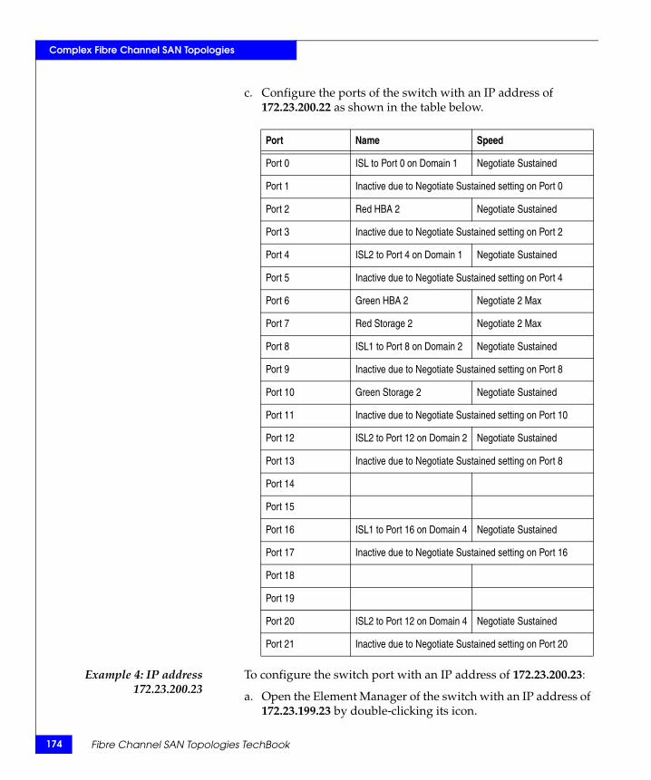
174
Complex Fibre Channel SAN Topologies
c. Configure the ports of the switch with an IP address of 172.23.200.22 as shown in the table below.
Example 4: IP address172.23.200.23
To configure the switch port with an IP address of 172.23.200.23:
a. Open the Element Manager of the switch with an IP address of 172.23.199.23 by double-clicking its icon.
Port Name Speed
Port 0 ISL to Port 0 on Domain 1 Negotiate Sustained
Port 1 Inactive due to Negotiate Sustained setting on Port 0
Port 2 Red HBA 2 Negotiate Sustained
Port 3 Inactive due to Negotiate Sustained setting on Port 2
Port 4 ISL2 to Port 4 on Domain 1 Negotiate Sustained
Port 5 Inactive due to Negotiate Sustained setting on Port 4
Port 6 Green HBA 2 Negotiate 2 Max
Port 7 Red Storage 2 Negotiate 2 Max
Port 8 ISL1 to Port 8 on Domain 2 Negotiate Sustained
Port 9 Inactive due to Negotiate Sustained setting on Port 8
Port 10 Green Storage 2 Negotiate Sustained
Port 11 Inactive due to Negotiate Sustained setting on Port 10
Port 12 ISL2 to Port 12 on Domain 2 Negotiate Sustained
Port 13 Inactive due to Negotiate Sustained setting on Port 8
Port 14
Port 15
Port 16 ISL1 to Port 16 on Domain 4 Negotiate Sustained
Port 17 Inactive due to Negotiate Sustained setting on Port 16
Port 18
Port 19
Port 20 ISL2 to Port 12 on Domain 4 Negotiate Sustained
Port 21 Inactive due to Negotiate Sustained setting on Port 20
Fibre Channel SAN Topologies TechBook

Complex Fibre Channel SAN Topologies
b. From the Configure menu, select ports menu.
c. Configure the ports of the switch with an IP address of 172.23.200.23 as shown in the table below.
Port Name Speed
Port 0 ISL to Port 8 on Domain 1 Negotiate Sustained
Port 1 Inactive due to Negotiate Sustained setting on Port 0
Port 2 Blue HBA 2 Negotiate Sustained
Port 3 Inactive due to Negotiate Sustained setting on Port 2
Port 4 ISL2 to Port 12 on Domain 1 Negotiate Sustained
Port 5 Inactive due to Negotiate Sustained setting on Port 4
Port 6 Blue Storage 2 Negotiate Sustained
Port 7 Inactive due to Negotiate Sustained setting on Port 6
Port 8 ISL1 to Port 16 on Domain 3 Negotiate Sustained
Port 9 Inactive due to Negotiate Sustained setting on Port 8
Port 10 Green Storage 4 Negotiate Sustained
Port 11 Inactive due to Negotiate Sustained setting on Port 10
Port 12 ISL2 to Port 20 on Domain 3 Negotiate Sustained
Port 13 Inactive due to Negotiate Sustained setting on Port 8
Port 14
Port 15
Port 16 ISL1 to Port 16 on Domain 4 Negotiate Sustained
Port 17 Inactive due to Negotiate Sustained setting on Port 16
Port 18
Port 19
Port 20 ISL2 to Port 20 on Domain 2 Negotiate Sustained
Port 21 Inactive due to Negotiate Sustained setting on Port 20
Four switch full mesh 175
176
Complex Fibre Channel SAN Topologies
Connect cables
To connect cables:
1. Connect ISLs.
a. Attach fiber cable between switches as shown in Figure 19 on page 163.
b. After all cables are connected, use Connectrix Manager to verify that all ISL connections are up.
c. Rearrange icons to accurately reflect the switch configuration and then persist the fabric.
Note: When looking at the topology view after persisting the fabric, you can immediately detect if something has changed in the environment. For example, if an ISL or device disappeared, yellow alert icons display. Because of this feature, it is recommended to always persist the fabric after changes have been made.
2. Connect the host and storage ports.
a. Attach fiber cable between switches and N_Ports.
Zone hosts and storage
To zone hosts and storage:
1. Open the Zoning dialog box in Connectrix Manager by right-clicking the appropriate fabric topology and selecting zoning menu.
2. Create a zone by clicking the New Zone button under the zones set Tree.
3. Provide a descriptive name for the zone. This case will zone Red host HBA and Red Storage 1, so RedHBA1_1470_8aa will be entered. Press Enter.
4. Locate, then click, Red Host HBA 1 (WWPN 10000000c938e554) in the potential zone members list.
5. Click the right-pointing arrow on the divider between the potential members list and the zones list to add the HBA to the zone.
6. Locate, then click, Red Storage 1 (WWPN 50060482cc19bf87) in the potential zone members list.
Fibre Channel SAN Topologies TechBook
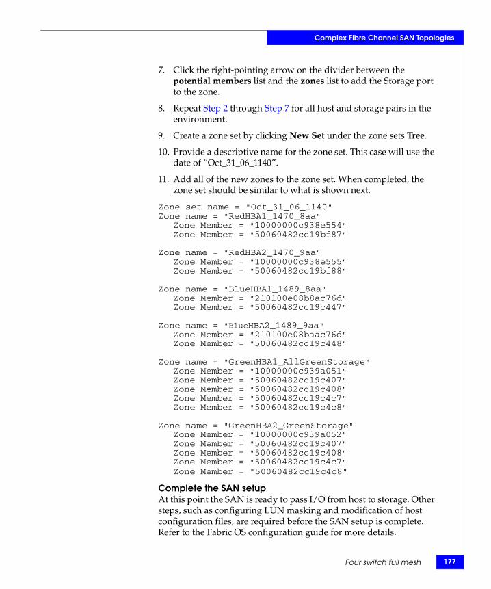
Complex Fibre Channel SAN Topologies
7. Click the right-pointing arrow on the divider between the potential members list and the zones list to add the Storage port to the zone.
8. Repeat Step 2 through Step 7 for all host and storage pairs in the environment.
9. Create a zone set by clicking New Set under the zone sets Tree.
10. Provide a descriptive name for the zone set. This case will use the date of “Oct_31_06_1140”.
11. Add all of the new zones to the zone set. When completed, the zone set should be similar to what is shown next.
Zone set name = "Oct_31_06_1140"Zone name = "RedHBA1_1470_8aa"
Zone Member = "10000000c938e554"Zone Member = "50060482cc19bf87"
Zone name = "RedHBA2_1470_9aa"Zone Member = "10000000c938e555"Zone Member = "50060482cc19bf88"
Zone name = "BlueHBA1_1489_8aa"Zone Member = "210100e08b8ac76d"Zone Member = "50060482cc19c447"
Zone name = "BlueHBA2_1489_9aa"Zone Member = "210100e08baac76d"Zone Member = "50060482cc19c448"
Zone name = "GreenHBA1_AllGreenStorage"Zone Member = "10000000c939a051"Zone Member = "50060482cc19c407"Zone Member = "50060482cc19c408"Zone Member = "50060482cc19c4c7"Zone Member = "50060482cc19c4c8"
Zone name = "GreenHBA2_GreenStorage"Zone Member = "10000000c939a052"Zone Member = "50060482cc19c407"Zone Member = "50060482cc19c408"Zone Member = "50060482cc19c4c7"Zone Member = "50060482cc19c4c8"
Complete the SAN setupAt this point the SAN is ready to pass I/O from host to storage. Other steps, such as configuring LUN masking and modification of host configuration files, are required before the SAN setup is complete. Refer to the Fabric OS configuration guide for more details.
Four switch full mesh 177
178
Complex Fibre Channel SAN Topologies
Configure security
Once the hosts and storage ports have been properly configured, the fabric should be secured.
Enable Enterprise Fabric Mode:
1. From the Connectrix Manager topology view, single-click a switch in the fabric that needs to be secured.
Note: Do not double-click and open the Element Manager.
2. Select Enterprise Fabric Mode under the Configure pull-down menu.
3. Click Activate.
4. Click Close.
Enable Port Binding:
1. From Connectrix Manager, double-click the switch with an IP address of 172.23.199.22 and its Element Manager will be displayed.
2. From the Configure pull-down menu, select Ports.
3. Right-click in the Port Binding column and select Bind All Ports To Attached WWN.
4. Click OK.
5. Repeat for other switches in the fabric.
Configure proactive monitoring and countermeasures
Configure throughput threshold alerts:
To configure threshold alerts:
1. Open a command prompt and Telnet to the switch by typing telnet 172.23.199.22.
2. Log in with the username and password of the switch.
3. Enter the Perf command.
4. Enter the thresh command.
5. Enter the throughput command.
6. Enter the addalert eightyPercent command.
7. Enter the addport eightyPercent all command.
Fibre Channel SAN Topologies TechBook
Complex Fibre Channel SAN Topologies
8. Enter the setParams eightyPercent 1 5 command.
9. Enter the setUtilPercentage eightyPercent 80 command.
10. Enter the setutiltype eightyPercent 3 command.
11. Enter the .. command.
12. Enter the setstate eightyPercent 1 command.
13. Enter the logo command.
Configure counter threshold alerts
Telnet into each switch and enter the following commands:
1. Enter the addAlert CTA1 command.
2. Enter the addPort CTA1 all command.
3. Enter the setCounter CTA1 18 command.
4. Enter the setParams CTA1 10000 30 command.
5. Enter the addAlert CTA2 command.
6. Enter the addPort CTA2 all command.
7. Enter the setCounter CTA2 10 command.
8. Enter the setParams CTA2 100 300 command.
9. Enter the addAlert CTA3 command.
10. Enter the addPort CTA3 all command.
11. Enter the setCounter CTA3 9 command.
12. Enter the setParams CTA3 40 300 command.
13. Enter the addAlert CTA4 command.
14. Enter the addPort CTA4 all command.
15. Enter the setCounter CTA4 9 command.
16. Enter the setParams CTA4 100 70560 command.
Enable the Counter threshold alerts:
1. Enter the .. command.
2. Enter the setState CTA1 1 command.
3. Enter the setState CTA2 1 command.
4. Enter the setState CTA3 1 command.
Four switch full mesh 179
180
Complex Fibre Channel SAN Topologies
5. Enter the setState CTA4 1 command.
To configure Port Fencing:
1. Click Configure and select Port Fencing from the list.
2. Enable the Default Security Policy by highlighting the entry and clicking Enable.
3. Enable the Default Link Level Policy by highlighting the entry and clicking Enable.
Disable unused interfaces:
1. From the Connectrix Manager topology view, select the Security tab.
2. Ensure that the appropriate fabric is selected in the fabrics list.
3. Under the Authentication tab, select a switch in the Product Configuration list.
4. Under the Users tab clear the Enable Telnet and Enable Web Sever checkbox.
Configure the other switch:
Repeat all the steps in the “Configure proactive monitoring and countermeasures” on page 178 to configure the other switch with the IP address 172.23.199.23, 172172.23.200.22, and 172.23.200.23.
Fibre Channel SAN Topologies TechBook
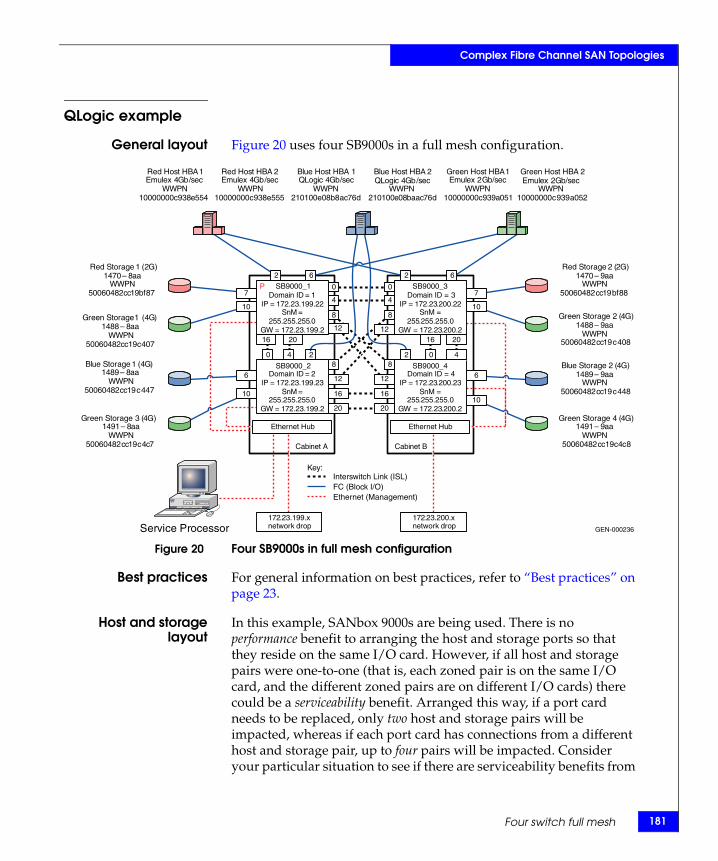
Complex Fibre Channel SAN Topologies
QLogic example
General layout Figure 20 uses four SB9000s in a full mesh configuration.
Figure 20 Four SB9000s in full mesh configuration
Best practices For general information on best practices, refer to “Best practices” on page 23.
Host and storagelayout
In this example, SANbox 9000s are being used. There is no performance benefit to arranging the host and storage ports so that they reside on the same I/O card. However, if all host and storage pairs were one-to-one (that is, each zoned pair is on the same I/O card, and the different zoned pairs are on different I/O cards) there could be a serviceability benefit. Arranged this way, if a port card needs to be replaced, only two host and storage pairs will be impacted, whereas if each port card has connections from a different host and storage pair, up to four pairs will be impacted. Consider your particular situation to see if there are serviceability benefits from
GEN-000236
Key:
Domain ID = 1 IP = 172 . 23 . 199 . 22
SnM = 255 . 255 . 255 . 0
GW = 172 . 23 . 199 . 2
Domain ID = 2 IP = 172 . 23 . 199 . 23
SnM = 255 . 255 . 255 . 0
GW = 172 . 23 . 199 . 2
Domain ID = 4IP = 172 . 23 . 200 . 23
SnM = 255 . 255 . 255 . 0
GW = 172 . 23 . 200 . 2
Domain ID = 3IP = 172 . 23 . 200 . 22
SnM = 255 . 255 . 255 . 0
GW = 172 . 23 . 200 . 2
172 . 23 . 199 . x network drop
Cabinet A Cabinet B
Service Processor
Ethernet Hub Ethernet Hub
172 . 23 . 200 . x network drop
Red Host HBA 1 Emulex 4 Gb / sec
WWPN 10000000 c 938 e 554
Red Host HBA 2 Emulex 4 Gb / sec
WWPN 10000000 c 938 e 555
Green Host HBA 1 Emulex 2 Gb / sec
WWPN 10000000 c 939 a 051
Green Host HBA 2 Emulex 2 Gb / sec
WWPN 10000000 c 939 a 052
Blue Host HBA 1QLogic 4 Gb / sec
WWPN 210100 e 08 b 8 ac 76 d
Blue Host HBA 2 QLogic 4 Gb / sec
WWPN 210100 e 08 baac 76 d
Red Storage 2 ( 2 G ) 1470 – 9 aa
WWPN 50060482 cc 19 bf 88
Red Storage 1 (2G)1470 – 8 aa
WWPN 50060482 cc 19 bf 87
Green Storage 1 ( 4 G ) 1488 – 8 aa
WWPN 50060482 cc 19 c 407
Green Storage 2 ( 4 G ) 1488 – 9 aa
WWPN 50060482 cc 19 c 408
Blue Storage 1 ( 4 G ) 1489 – 8 aa
WWPN 50060482 cc 19 c 447
Blue Storage 2 ( 4 G ) 1489 – 9 aa
WWPN 50060482 cc 19 c 448
Green Storage 3 ( 4 G ) 1491 – 8 aa
WWPN 50060482 cc 19 c 4 c 7
Green Storage 4 ( 4 G ) 1491 – 9 aa
WWPN 50060482 cc 19 c 4 c 8
2 2
0 0
4 4
6 6
0 4 2 2 0 4
16 20
16
20
12
8
8
12
8
12
8
12
16
20
7
10
6
10
16 20
7
10
6
10
Interswitch Link (ISL) FC (Block I/O) Ethernet (Management)
P
SB9000_2
SB9000_1
SB9000_4
SB9000_3
Four switch full mesh 181
182
Complex Fibre Channel SAN Topologies
any particular arrangement, even if no performance benefits are realized.
For general information on host and storage layout, refer to “Host and storage layout” on page 30.
Switch and fabricmanagement
For general information on switch and fabric management, refer to “Switch and fabric management” on page 32.
Security For QLogic security information that may be applicable, refer to “Security” on page 109.
For general information on security, refer to “Security” on page 36.
Setting up thistopology
Assumptions specific to this case study:
◆ The switches are installed in an EMC-supplied cabinet
• For installation instructions, refer to the Connectrix EC-1500 Cabinet Installation and Setup Manual, available at Powerlink.
◆ The proper power receptacles have been provided by the customer.
• For switch power requirements, refer to EMC Connectrix SAN Products Data Reference Manual, available through the E-Lab Interoperability Navigator, Topology Resource Center tab, at http://elabnavigator.EMC.com.
• For Cabinet power requirements, refer to the Connectrix EC-1500 Cabinet Installation and Setup Manual, available at Powerlink.
◆ The switches have not been connected to the power source and are not powered on.
Note: QLogic switches ship with a default IP address of 10.0.0.1. If all of the switches are powered on and connected to the hub in the switch cabinet, communication with the switch using the network interfaces will not be possible and you will have to program the IP addresses using the serial port. This example assumes that the serial port will not be used and the IP addresses will be programmed using the network interface.
◆ Network drops, IP addresses, Subnet mask, and gateway have been provided by the customer.
Fibre Channel SAN Topologies TechBook

Complex Fibre Channel SAN Topologies
• For switch or cabinet network requirements, refer to EMC Connectrix SAN Products Data Reference Manual, available through the E-Lab Interoperability Navigator, Topology Resource Center tab, at http://elabnavigator.EMC.com.
Note: QLogic switches can be either attached to the Ethernet hub that comes with the cabinet, or directly connected to the customer’s LAN. In both cases, the switches can be placed on either a public or private network. There are advantages to both configurations. For a complete discussion, refer to "Public versus private" in the Networked Storage Concepts and Protocols TechBook, available through the E-Lab Interoperability Navigator, Topology Resource Center tab, at http://elabnavigator.EMC.com.
In this example, it is assumed that the customer has provided two Ethernet cables and that one of them is on the 172.23.199.x network and that the other is connected to the 172.23.200.x network.
◆ License keys have been obtained.
• To obtain a license key, go to the URL listed on the transaction code certificate that shipped with the product.
◆ A Windows workstation will be used to configure the IP addresses of the switches. The workstation must be configured for an IP address of 10.1.1.1.253.
◆ A null modem cable is available.
◆ The customer has provided a temporary password that will be used as the default password when configuring the IP address.
◆ Enterprise Fabric Suite 2007 (EFS 2007) will be used to manage this fabric and the installation kit for this management application is available on a disk that comes with the SB90000 product.
◆ EFS 2007 is not already installed on the workstation.
Install the Enterprise Fabric Suite 2007
To install the Enterprise Fabric Suite 2007:
1. Close all the applications currently running on the management workstation and insert the Enterprise Fabric Suite 2007 Installation Disk into the CD-ROM drive.
2. In the upper left corner of the Product information screen, click Management Software.
Four switch full mesh 183
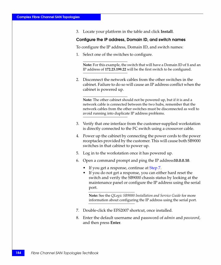
184
Complex Fibre Channel SAN Topologies
3. Locate your platform in the table and click Install.
Configure the IP address, Domain ID, and switch names
To configure the IP address, Domain ID, and switch names:
1. Select one of the switches to configure.
Note: For this example, the switch that will have a Domain ID of 1 and an IP address of 172.23.199.22 will be the first switch to be configured.
2. Disconnect the network cables from the other switches in the cabinet. Failure to do so will cause an IP address conflict when the cabinet is powered up.
Note: The other cabinet should not be powered up, but if it is and a network cable is connected between the two hubs, remember that the network cables from the other switches must be disconnected as well to avoid running into duplicate IP address problems.
3. Verify that one interface from the customer-supplied workstation is directly connected to the FC switch using a crossover cable.
4. Power up the cabinet by connecting the power cords to the power receptacles provided by the customer. This will cause both SB9000 switches in that cabinet to power up.
5. Log in to the workstation once it has powered up.
6. Open a command prompt and ping the IP address10.0.0.10.
• If you get a response, continue at Step 7. • If you do not get a response, you can either hard reset the
switch and verify the SB9000 chassis status by looking at the maintenance panel or configure the IP address using the serial port.
Note: See the QLogic SB9000 Installation and Service Guide for more information about configuring the IP address using the serial port.
7. Double-click the EFS2007 shortcut, once installed.
8. Enter the default username and password of admin and password, and then press Enter.
Fibre Channel SAN Topologies TechBook
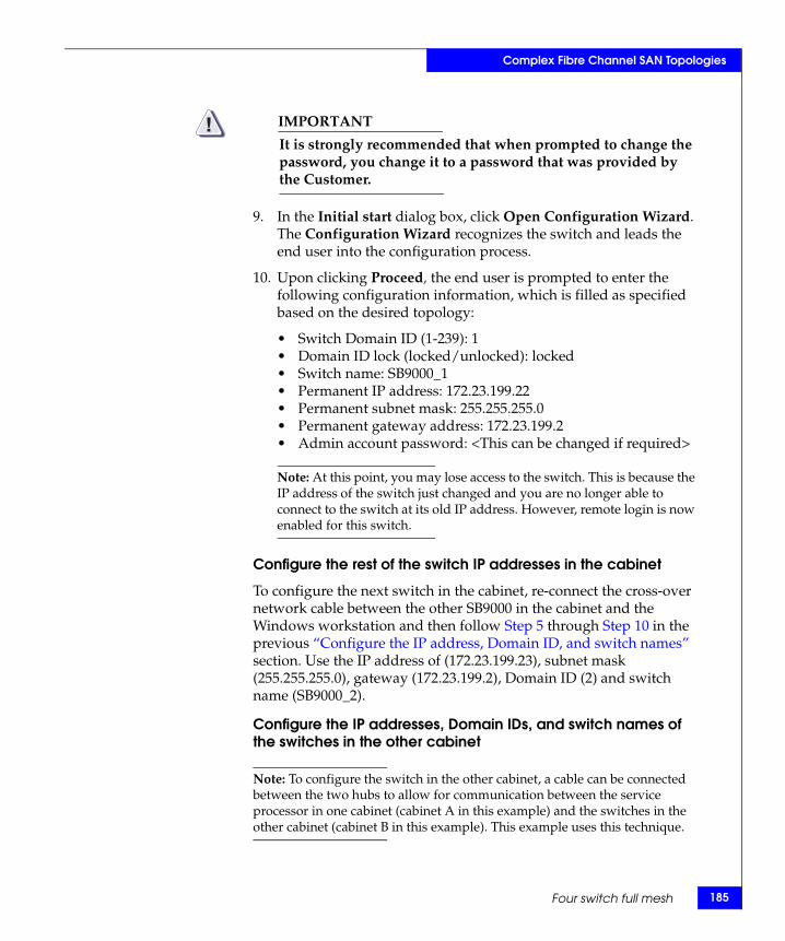
Complex Fibre Channel SAN Topologies
IMPORTANT!It is strongly recommended that when prompted to change the password, you change it to a password that was provided by the Customer.
9. In the Initial start dialog box, click Open Configuration Wizard. The Configuration Wizard recognizes the switch and leads the end user into the configuration process.
10. Upon clicking Proceed, the end user is prompted to enter the following configuration information, which is filled as specified based on the desired topology:
• Switch Domain ID (1-239): 1• Domain ID lock (locked/unlocked): locked• Switch name: SB9000_1• Permanent IP address: 172.23.199.22• Permanent subnet mask: 255.255.255.0• Permanent gateway address: 172.23.199.2• Admin account password: <This can be changed if required>
Note: At this point, you may lose access to the switch. This is because the IP address of the switch just changed and you are no longer able to connect to the switch at its old IP address. However, remote login is now enabled for this switch.
Configure the rest of the switch IP addresses in the cabinet
To configure the next switch in the cabinet, re-connect the cross-over network cable between the other SB9000 in the cabinet and the Windows workstation and then follow Step 5 through Step 10 in the previous “Configure the IP address, Domain ID, and switch names” section. Use the IP address of (172.23.199.23), subnet mask (255.255.255.0), gateway (172.23.199.2), Domain ID (2) and switch name (SB9000_2).
Configure the IP addresses, Domain IDs, and switch names of the switches in the other cabinet
Note: To configure the switch in the other cabinet, a cable can be connected between the two hubs to allow for communication between the service processor in one cabinet (cabinet A in this example) and the switches in the other cabinet (cabinet B in this example). This example uses this technique.
Four switch full mesh 185
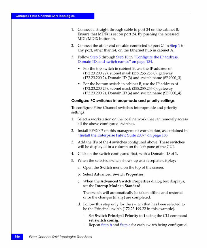
186
Complex Fibre Channel SAN Topologies
1. Connect a straight through cable to port 24 on the cabinet B. Ensure that MDIX is set on port 24. By pushing the recessed MDI/MDIX button in.
2. Connect the other end of cable connected to port 24 in Step 1 to any port, other than 24, on the Ethernet hub in cabinet A.
3. Follow Step 5 through Step 10 in “Configure the IP address, Domain ID, and switch names” on page 184.
• For the top switch in cabinet B, use the IP address of (172.23.200.22), subnet mask (255.255.255.0), gateway (172.23.200.2), Domain ID (3) and switch name (SB9000_3).
• For the bottom switch in cabinet B, use the IP address of (172.23.200.23), subnet mask (255.255.255.0), gateway (172.23.200.2), Domain ID (4) and switch name (SB9000_4).
Configure FC switches interopmode and priority settings
To configure Fibre Channel switches interopmode and priority settings:
1. Select a workstation on the local network that can remotely access all the above configured switches.
2. Install EFS2007 on this management workstation, as explained in “Install the Enterprise Fabric Suite 2007” on page 183.
3. Add the IPs of the 4 switches configured above. These switches will be displayed in a column on the left pane of the GUI.
4. Click on the switch configured first, with a Domain ID of 1.
5. When the selected switch shows up as a faceplate display:
a. Open the Switch menu on the top of the screen.
b. Select Advanced Switch Properties.
c. When the Advanced Switch Properties dialog box displays, set the Interop Mode to Standard.
The switch will automatically be taken offline and restored once the changes (if any) are completed.
d. Follow this step only for the switch that has been selected to be the Principal switch (172.23.199.22 in this example).
– Set Switch Principal Priority to 1 using the CLI command set switch config.
– Repeat Step b and Step c for each switch being configured.
Fibre Channel SAN Topologies TechBook

Complex Fibre Channel SAN Topologies
6. Configure the switch ports.
a. From the faceplate display, follow the steps below to change the symbolic port name:
– Open the faceplate display and select the respective port.– Open the Port menu and select Port Symbolic Name.– In the Port symbolic name dialog box, enter a new name
for the port in the Set Port Symbolic Name field as given in the tables shown in Step d.
b. The characteristics or port settings for the 1 Gb/2 Gb/4 Gb and 10 Gb ports are configured using the Port Properties setting. To open the corresponding type of Port Properties dialog box, select one or more ports, open the Port menu and select Port Properties.
c. The Port Properties dialog box can be used to change the following settings:
– Port state– Port type– Port speed
d. For this case study, the ports can be configured as per the following tables:
Switch 1: SB9000_1:
Port # Symbolic port name Port type Port speed
0 ISL to SB9000_3 E_Port AutoNeg.
2 Red Host HBA 1 F_Port AutoNeg.
4 ISL to SB9000_3 E_Port AutoNeg.
6 Green Host HBA 1 F_Port AutoNeg.
7 Red Storage 1 F_Port AutoNeg.
8 ISL to SB9000_4 E_Port AutoNeg.
10 Green Storage 1 F_Port AutoNeg.
12 ISL to SB9000_4 E_Port AutoNeg.
16 ISL to SB9000_2 E_Port AutoNeg.
20 ISL to SB9000_2 E_Port AutoNeg.
Four switch full mesh 187
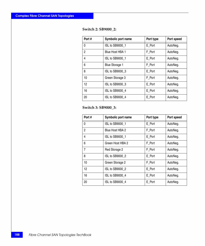
188
Complex Fibre Channel SAN Topologies
Switch 2: SB9000_2:
Switch 3: SB9000_3:
Port # Symbolic port name Port type Port speed
0 ISL to SB9000_1 E_Port AutoNeg.
2 Blue Host HBA 1 F_Port AutoNeg.
4 ISL to SB9000_1 E_Port AutoNeg.
6 Blue Storage 1 F_Port AutoNeg.
8 ISL to SB9000_3 E_Port AutoNeg.
10 Green Storage 3 F_Port AutoNeg.
12 ISL to SB9000_3 E_Port AutoNeg.
16 ISL to SB9000_4 E_Port AutoNeg.
20 ISL to SB9000_4 E_Port AutoNeg.
Port # Symbolic port name Port type Port speed
0 ISL to SB9000_1 E_Port AutoNeg.
2 Blue Host HBA 2 F_Port AutoNeg.
4 ISL to SB9000_1 E_Port AutoNeg.
6 Green Host HBA 2 F_Port AutoNeg.
7 Red Storage 2 F_Port AutoNeg.
8 ISL to SB9000_2 E_Port AutoNeg.
10 Green Storage 2 F_Port AutoNeg.
12 ISL to SB9000_2 E_Port AutoNeg.
16 ISL to SB9000_4 E_Port AutoNeg.
20 ISL to SB9000_4 E_Port AutoNeg.
Fibre Channel SAN Topologies TechBook

Complex Fibre Channel SAN Topologies
Switch 4: SB9000_4:
Repeat Step 1 through Step 6 for the other three configured switches.
Connect cables
To connect cables:
1. Connect ISLs.
a. Attach the fiber cable between switches as shown in Figure 20 on page 181.
b. After all cables are connected, use the EFS 2007 faceplate data manager on the lower portion of the interface to verify that all ISL connections are up.
c. Re-arrange icons to accurately reflect the switch configuration.
2. Connect host and storage ports.
a. Attach fiber cable between switches and N_Ports.
Zone hosts and storage
To zone hosts and storage:
1. Before creating any zones and enabling zoning, use the Edit Zoning config dialog box to change the Interop Auto save, Default Zone, and Discard inactive parameters.
Port # Symbolic port name Port type Port speed
0 ISL to SB9000_3 E_Port AutoNeg.
2 Blue Host HBA 2 F_Port AutoNeg.
4 ISL to SB9000_3 E_Port AutoNeg.
6 Blue Storage 2 F_Port AutoNeg.
8 ISL to SB9000_1 E_Port AutoNeg.
10 Green Storage 4 F_Port AutoNeg.
12 ISL to SB9000_1 E_Port AutoNeg.
16 ISL to SB9000_2 E_Port AutoNeg.
20 ISL to SB9000_2 E_Port AutoNeg.
Four switch full mesh 189

190
Complex Fibre Channel SAN Topologies
• The Interop Auto save parameter (which determines whether any active zone changes that a switch receives from any other switch in the fabric must be saved to the zoning database of the switch) must be set to False.
• The Default Zone (which allows all N_Ports to see each other in the absence of any active zones) must be set to False.
• The Discard inactive parameter (which automatically removes or pulls out inactive zones from an active zoneset) must be set to False.
2. Open the Edit Zoning toolbar from the Zoning menu on the faceplate display.
3. Create a zone by clicking Create Zone.
4. Provide a descriptive name for the zone. This example will zone “Red host HBA 1” and “Red Storage 1”. Type “RedHBA1_1470_8aa" and press Enter.
5. Locate, then click, “Red Host HBA 1” (WWPN 10000000c938e554) in the Potential zone members list.
6. Click Add Member to add the selected HBA to the zone created in Step 4.
7. Locate and click “Red Storage 1” (WWPN 50060482cc19bf87) in the Potential zone members list.
8. Repeat Step 3 through Step 7 for all host and storage pairs in the environment.
9. Create a zone set by clicking Create Zone Set.
10. Provide a descriptive name for the zone set. This example will use the date of “Oct_31_06_1140”.
11. Add all of the zones created in Step 4 through Step 8 to the zone set by dragging the zones listed to the left into the zoneset created in Step 10.
12. To activate this zoneset, select Activate Zone Set from the Zoning Edit menu. Select a zoneset from the Select zoneset pull-down menu and click Activate.
Fibre Channel SAN Topologies TechBook
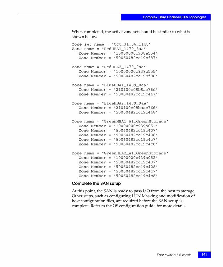
Complex Fibre Channel SAN Topologies
When completed, the active zone set should be similar to what is shown below.
Zone set name = "Oct_31_06_1140"Zone name = "RedHBA1_1470_8aa"
Zone Member = "10000000c938e554"Zone Member = "50060482cc19bf87"
Zone name = "RedHBA2_1470_9aa"Zone Member = "10000000c938e555"Zone Member = "50060482cc19bf88"
Zone name = "BlueHBA1_1489_8aa"Zone Member = "210100e08b8ac76d"Zone Member = "50060482cc19c447"
Zone name = "BlueHBA2_1489_9aa"Zone Member = "210100e08baac76d"Zone Member = "50060482cc19c448"
Zone name = "GreenHBA1_AllGreenStorage"Zone Member = "10000000c939a051"Zone Member = "50060482cc19c407"Zone Member = "50060482cc19c408"Zone Member = "50060482cc19c4c7"Zone Member = "50060482cc19c4c8"
Zone name = "GreenHBA2_AllGreenStorage"Zone Member = "10000000c939a052"Zone Member = "50060482cc19c407"Zone Member = "50060482cc19c408"Zone Member = "50060482cc19c4c7"Zone Member = "50060482cc19c4c8"
Complete the SAN setup
At this point, the SAN is ready to pass I/O from the host to storage. Other steps, such as configuring LUN Masking and modification of host configuration files, are required before the SAN setup is complete. Refer to the OS configuration guide for more details.
Four switch full mesh 191
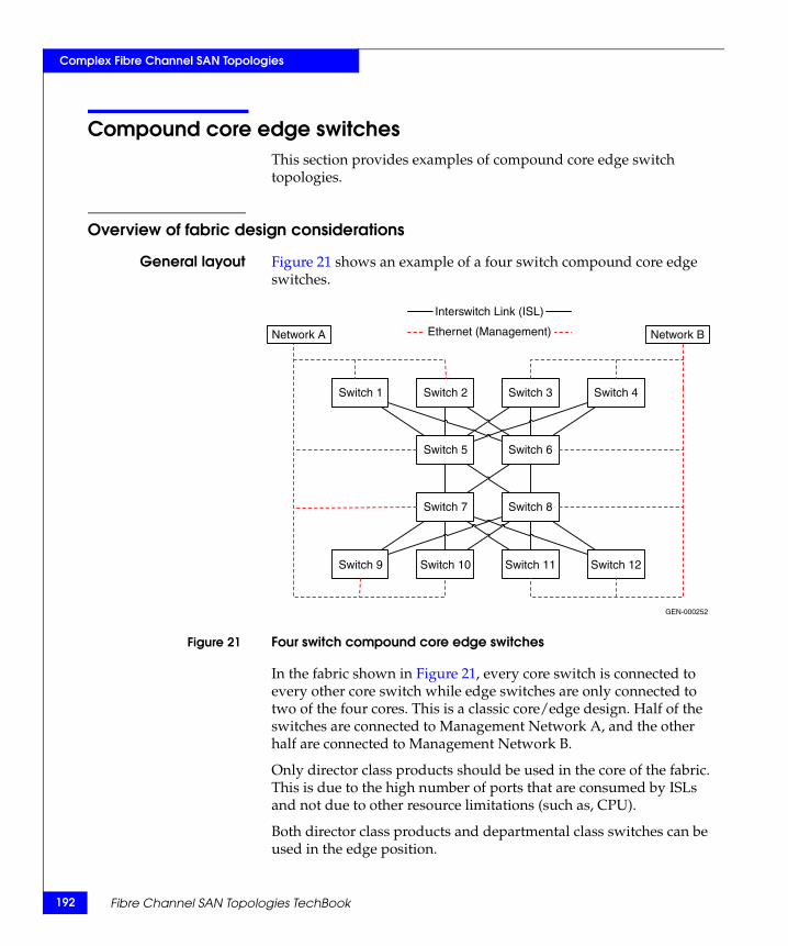
192
Complex Fibre Channel SAN Topologies
Compound core edge switchesThis section provides examples of compound core edge switch topologies.
Overview of fabric design considerations
General layout Figure 21 shows an example of a four switch compound core edge switches.
Figure 21 Four switch compound core edge switches
In the fabric shown in Figure 21, every core switch is connected to every other core switch while edge switches are only connected to two of the four cores. This is a classic core/edge design. Half of the switches are connected to Management Network A, and the other half are connected to Management Network B.
Only director class products should be used in the core of the fabric. This is due to the high number of ports that are consumed by ISLs and not due to other resource limitations (such as, CPU).
Both director class products and departmental class switches can be used in the edge position.
Switch 1 Switch 2 Switch 3
Switch 5 Switch 6
Switch 7 Switch 8
Switch 4
Switch 9 Switch 10 Switch 11 Switch 12
Network A Network B
Interswitch Link (ISL)
Ethernet (Management)
GEN-000252
Fibre Channel SAN Topologies TechBook

Complex Fibre Channel SAN Topologies
Best practices Specific information on a compound core edge switch follows.
◆ Layout the host and storage connectivity such that if a switch fails, not all of a particular hosts storage becomes inaccessible.
◆ The use of two separate management networks is more common with balanced fabrics, but it can still be employed when only one fabric is used.
◆ ISL subscription best practice — While planning the SAN, keep track of the number of host and storage pairs that would be utilizing the ISLs between domains. As a general best practice, if two switches are connected by ISLs, ensure that there is a minimum of two ISLs between them, and that there are no more than six initiator and target pairs per ISL. For example, if 14 initiators access a total of 14 targets between two domains, a total of three ISLs are necessary. This best practice should not be applied blindly when setting up a configuration. Consider the applications that will use the ISLs.
For general information on best practices for all SANs, refer to “Best practices” on page 23.
Host and storagelayout
Specific information a compound core edge switch follows.
In the examples that follow, host and storage pairs are located in the following locations:
◆ Host on the edge and storage on the edge (Red)◆ Host on the core and storage on the core (Blue)◆ Host on the core and storage on the edge (Green)
The decision on where to place these host and storage pairs was not arbitrary. These were deliberately placed in areas that may not typically be thought of as "good" places to attach host and storage ports. This was done to stress the point that the only good place to attach host and storage ports is where it makes the most sense, given the customer’s environment.
For general information on host and storage layout for all SANs, refer to “Host and storage layout” on page 30.
Switch and fabricmanagement
For general information on switch and fabric management for all SANs, refer to “Switch and fabric management” on page 32.
Security For general information on security for all SANs, refer to “Security” on page 36.
Compound core edge switches 193
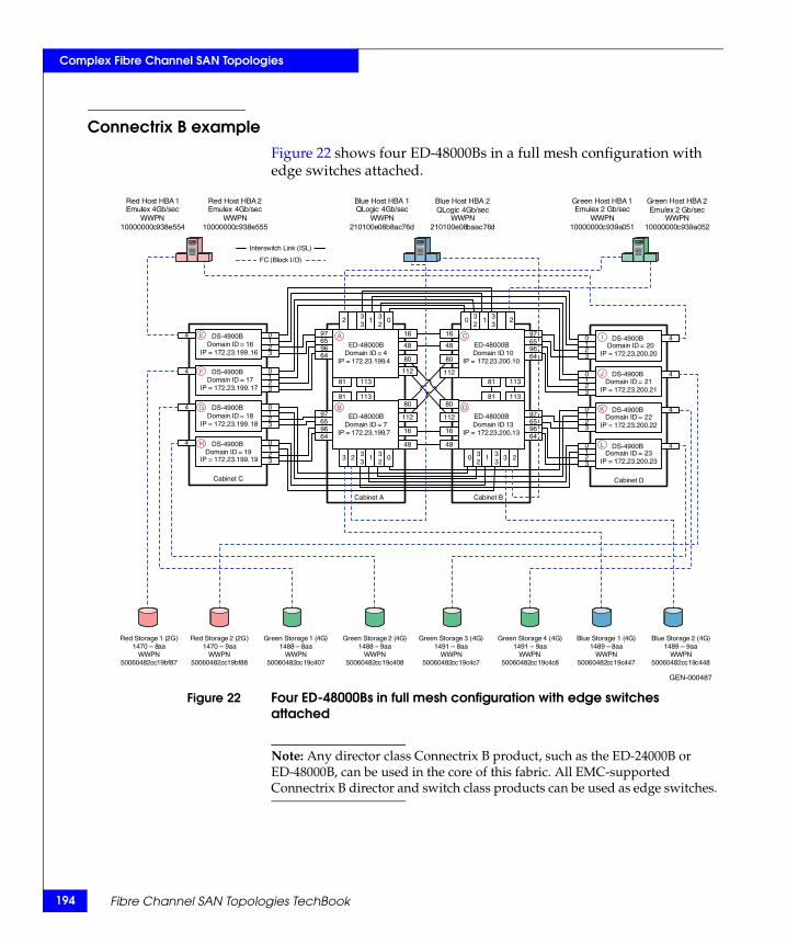
194
Complex Fibre Channel SAN Topologies
Connectrix B exampleFigure 22 shows four ED-48000Bs in a full mesh configuration with edge switches attached.
Figure 22 Four ED-48000Bs in full mesh configuration with edge switches attached
Note: Any director class Connectrix B product, such as the ED-24000B or ED-48000B, can be used in the core of this fabric. All EMC-supported Connectrix B director and switch class products can be used as edge switches.
ED-48000BDomain ID = 4
IP = 172.23.199.4
Domain ID = 7IP = 172.23.199.7
Domain ID 13IP = 172.23.200.13
Domain ID 10IP = 172.23.200.10
FC (Block I/O
Interswitch Link (ISL
)
)
Cabinet A Cabinet B
Red Host HBA 1Emulex 4Gb/sec
WWPN10000000c938e554
Red Host HBA 2Emulex 4Gb/sec
WWPN10000000c938e555
Green Host HBA 1Emulex 2 Gb/sec
WWPN10000000c939a051
Green Host HBA 2Emulex 2 Gb/sec
WWPN10000000c939a052
Blue Host HBA 1QLogic 4Gb/sec
WWPN210100e08b8ac76d
Blue Host HBA 2QLogic 4Gb/sec
WWPN210100e08baac76d
Red Storage 2 (2G)1470 – 9aa
WWPN50060482cc19bf88
Red Storage 1 (2G)1470 – 8aa
WWPN50060482cc19bf87
Green Storage 1 (4G)1488 – 8aa
WWPN50060482cc19c407
Green Storage 2 (4G)1488 – 9aa
WWPN50060482cc19c408
Blue Storage 1 (4G)1489 – 8aa
WWPN50060482cc19c447
Blue Storage 2 (4G)1489 – 9aa
WWPN50060482cc19c448
Green Storage 3 (4G)1491 – 8aa
WWPN50060482cc19c4c7
Green Storage 4 (4G)1491 – 9aa
WWPN50060482cc19c4c8
16 16
48 48
81 113 81 113
81 113
16
48
112
80
80
112
80
112
80
112
16
48
81 113
Cabinet C
DS-4900BDomain ID = 16
IP = 172.23.199.16
Domain ID = 17IP = 172.23.199.17
Domain ID = 18IP = 172.23.199.18
Domain ID = 19IP = 172.23.199.19
Cabinet D
Domain ID = 20IP = 172.23.200.20
Domain ID = 21IP = 172.23.200.21
Domain ID = 22IP = 172.23.200.22
Domain ID = 23IP = 172.23.200.23
10
23
6597
9664
6597
9664
10
23
10
23
10
23
10
23
6597
9664
6597
9664
10
23
10
23
10
23
0 32
1 33
2
0 32
1 33
3 23 2 33
1 32
0
2 33
1 32
0
4
4
4
4
4
4
4
4
GEN-000487
DS-4900B
DS-4900B
DS-4900B
DS-4900B
DS-4900B
DS-4900B
DS-4900B
ED-48000B
ED-48000B
ED-48000B
E
F
I
J
K
L
A
B
C
DG
H
Fibre Channel SAN Topologies TechBook
Complex Fibre Channel SAN Topologies
Best practices Specific information for this example is as follows:
While connecting the edge switches to the ED-48000B director switch it is recommended to be conversant with the architecture of the ED-48000B, its local switching capability, and the over-subscription management of the different switch port blades (i.e., the supported 16-port, 32-port, and 48-port blades) while designing scalable fabrics. An understanding of the product design will help utilize the ports on the switch blades for switch or host/target connectivity, enabling the simultaneous uncongested ports on all ports as long as simple best practices are followed.
Refer to the following link for further information on this subject: http://www.brocade.com/products/competitive/directors.jsp
For general information on best practices for a compound core edge switch, refer to “Best practices” on page 193. For Connectrix B specific best practices, refer to “Connectrix B” on page 26.
Host and storagelayout
To ensure fairness and increase the reliability of the SAN by eliminating any single point of overall failure and minimizing the impact that any single hardware failure would have, the N_Port and E_Port connections have been spread out on the ED-48000B over as many switch blade ports as possible.
The N_Port and E_Port connections on the DS-4900B are attached without any special considerations since there are no benefits to performance or reliability by spreading out the connections on the DS-4900B. In case the user wants to configure a trunk on the Connectrix B series switches, it is necessary that all ports in a given ISL trunk reside within an ASIC group on each end of the link. On 2 Gb/s switches, port groups are built on contiguous 4-port groups, called quads. On 4 Gb/s switches, like the Connectrix DS-48000B and the DS-4900B in this example, trunking port groups are built on contiguous 8-port groups, called octets. In these products, there are four octets: ports 0-7, 8-15, 16-23, and 24-31. The user must use the ports within a group as specified above to form an ISL trunk. It is also possible to configure multiple trunks within a port group.
For this case study, an attempt is made to connect ISLs to the same number ports on both switches to help assist with troubleshooting should the need arise.
For general information on host and storage layout for a compound core edge switch, refer to “Host and storage layout” on page 193.
Compound core edge switches 195
196
Complex Fibre Channel SAN Topologies
Switch and fabricmanagement
In this example, both CLI and Web Tools will be used to set up the compound core edge SAN topology, with the four Connectrix ED-48000Bs at the core and the eight DS-4900Bs at the edge.
For general information on switch and fabric management for a compound core edge switch, refer to “Switch and fabric management” on page 193. Specific information for this example follows.
Security The connectivity and device discovery for a large Connectrix B switch fabric may be secured by appointing the following binding techniques. All these are Connectrix B specific features.
◆ Fabric Binding is a security method for restricting switches within a multiple-switch fabric. The SCC policy prevents unauthorized switches from joining a fabric. Switches are authenticated using digital certificates and unique private keys provided to the Switch Link Authentication Protocol (SLAP).
◆ Switch Binding is a security method for restricting devices that connect to a particular switch. If the device is another switch, this is handled by the SCC policy. If the device is a host or storage device, the Device Connection Control (DCC) policy binds those devices to a particular switch. Policies range from completely restrictive to reasonably flexible, based upon customer needs.
◆ Port Binding is a security method for restricting host or storage devices that connect to particular switch ports. The DCC policy also binds device ports to switch ports. Policies range from completely restrictive to reasonably flexible, based on customer needs. For switches running Fabric OS v5.2.0 and later, the SCC ACL with strict fabric-wide consistency can also be used for Switch Binding in addition to the Secure Fabric OS mechanism.
The method to enable SCC and DCC policies has been provided at the end of the fabric configuration steps for this case study (refer to “Enabling the Switch Connection Policy (SCC)” on page 209).
For general information on security for a compound core edge switch, refer to “Security” on page 193. Specific information for this example follows.
Setting up thistopology
Assumption specific to this case study:
◆ The ED-48000B director class and the DS-4900B edge switches are installed in an EMC-supplied cabinet.
Fibre Channel SAN Topologies TechBook
Complex Fibre Channel SAN Topologies
For installation instructions, refer to the Connectrix EC-1500 Cabinet Installation and Setup Manual, accessible from Powerlink.
◆ The proper power receptacles have been provided by the customer.
For switch power requirements, refer to “Connectrix B series directors and switches” in the EMC Connectrix SAN Products Data Reference Manual, available through the E-Lab Interoperability Navigator, Topology Resource Center tab, at http://elabnavigator.EMC.com.
◆ The switches have not been connected to the power source and are not powered on.
◆ Network drops, IP addresses, subnet mask, and gateway have been provided by the customer.
For switch or cabinet network requirements, refer to “Connectrix B series directors and switches” in the EMC Connectrix SAN Products Data Reference Manual, available through the E-Lab Interoperability Navigator, Topology Resource Center tab, at http://elabnavigator.EMC.com.
◆ The proper number of line cards have been installed into the ED-48000Bs.
For help in determining how many ports are required, refer to "Determining customer requirements" in the Networked Storage Concepts and Protocols TechBook, available through the E-Lab Interoperability Navigator, Topology Resource Center tab, at http://elabnavigator.EMC.com.
◆ License keys have been obtained.
Go to the URL listed on the transaction code certificate that shipped with the product to get the license key.
◆ The customer has provided a temporary password that will be used as the default password when configuring the IP address.
◆ An EMC-supported Brocade FOS is installed on all switches in the fabric.
Refer to the EMC Support Matrix for the most current support information.
Compound core edge switches 197
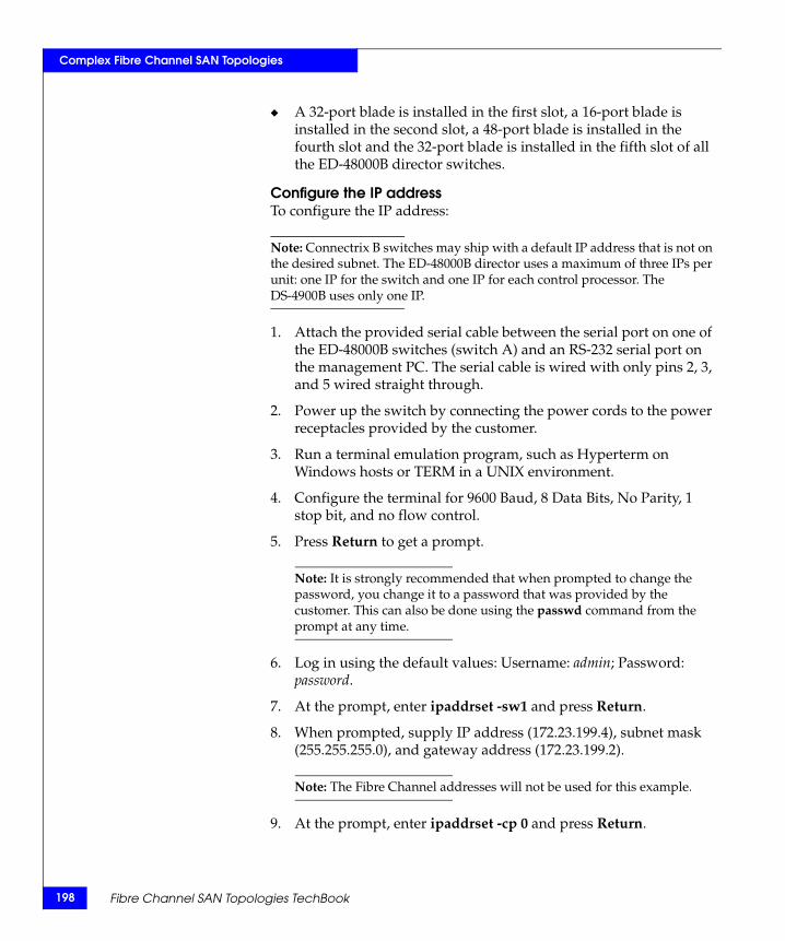
198
Complex Fibre Channel SAN Topologies
◆ A 32-port blade is installed in the first slot, a 16-port blade is installed in the second slot, a 48-port blade is installed in the fourth slot and the 32-port blade is installed in the fifth slot of all the ED-48000B director switches.
Configure the IP addressTo configure the IP address:
Note: Connectrix B switches may ship with a default IP address that is not on the desired subnet. The ED-48000B director uses a maximum of three IPs per unit: one IP for the switch and one IP for each control processor. The DS-4900B uses only one IP.
1. Attach the provided serial cable between the serial port on one of the ED-48000B switches (switch A) and an RS-232 serial port on the management PC. The serial cable is wired with only pins 2, 3, and 5 wired straight through.
2. Power up the switch by connecting the power cords to the power receptacles provided by the customer.
3. Run a terminal emulation program, such as Hyperterm on Windows hosts or TERM in a UNIX environment.
4. Configure the terminal for 9600 Baud, 8 Data Bits, No Parity, 1 stop bit, and no flow control.
5. Press Return to get a prompt.
Note: It is strongly recommended that when prompted to change the password, you change it to a password that was provided by the customer. This can also be done using the passwd command from the prompt at any time.
6. Log in using the default values: Username: admin; Password: password.
7. At the prompt, enter ipaddrset -sw1 and press Return.
8. When prompted, supply IP address (172.23.199.4), subnet mask (255.255.255.0), and gateway address (172.23.199.2).
Note: The Fibre Channel addresses will not be used for this example.
9. At the prompt, enter ipaddrset -cp 0 and press Return.
Fibre Channel SAN Topologies TechBook

Complex Fibre Channel SAN Topologies
10. When prompted, supply hostname (48K_1_5), IP address (172.23.199.5), subnet mask (255.255.255.0), and gateway address (172.23.199.2).
11. At the prompt, enter ipaddrset -cp 1 and press Return.
12. When prompted, supply hostname (48K_1_6), IP address (172.23.199.6), subnet mask (255.255.255.0), and gateway address (172.23.199.2).
13. Power down the switch and disconnect the serial cable.
14. Connect the switch to a 10/100BaseT Ethernet connection.
15. Power up the switch. The switch can now be accessed with IP-based management.
16. Repeat these steps for the other three switches B, C, and D using the following information:
17. Repeat Step 1 through Step 6 for all of the DS-4900Bs: Switch E, F, G, H, I, J, K and L one-by-one, and then execute the following steps on switch E:
18. At the prompt, enter ipaddrset and press Return.
19. When prompted, supply IP address (172.23.199.16), subnet mask (255.255.255.0), and gateway address (172.23.199.2).
20. Power down the switch and disconnect the serial cable.
21. Connect the switch to a 10/100BaseT Ethernet connection.
22. Power up the switch. The switch can now be accessed with IP-based management.
Domain ID Switch IP CP0 IP CP0 Name CP1 IP CP1 Name
Switch A 4 172.23.199.4 172.23.199.5 48K_1_5 172.23.199.6 48K_1_6
Switch B 7 172.23.199.7 172.23.199.8 48K_1_8 172.23.199.9 48K_1_9
Switch C 10 172.23.200.10 172.23.200.11 48K_1_11 172.23.200.12 48K_1_12
Switch D 13 172.23.200.13 172.23.200.14 48K_1_14 172.23.200.15 48K_1_15
Compound core edge switches 199
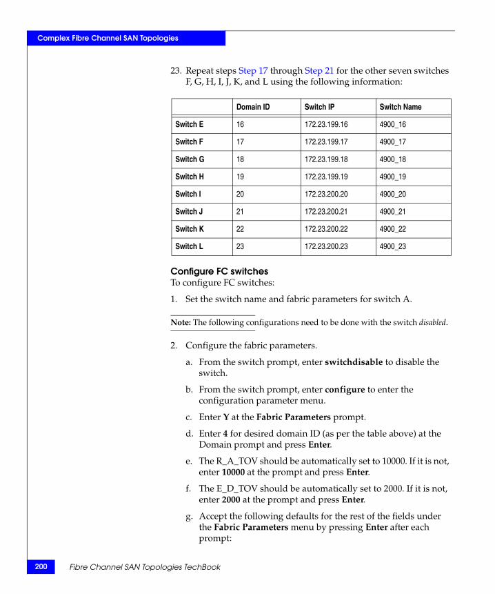
200
Complex Fibre Channel SAN Topologies
23. Repeat steps Step 17 through Step 21 for the other seven switches F, G, H, I, J, K, and L using the following information:
Configure FC switchesTo configure FC switches:
1. Set the switch name and fabric parameters for switch A.
Note: The following configurations need to be done with the switch disabled.
2. Configure the fabric parameters.
a. From the switch prompt, enter switchdisable to disable the switch.
b. From the switch prompt, enter configure to enter the configuration parameter menu.
c. Enter Y at the Fabric Parameters prompt.Fann
d. Enter 4 for desired domain ID (as per the table above) at the Domain prompt and press Enter.
e. The R_A_TOV should be automatically set to 10000. If it is not, enter 10000 at the prompt and press Enter.
f. The E_D_TOV should be automatically set to 2000. If it is not, enter 2000 at the prompt and press Enter.
g. Accept the following defaults for the rest of the fields under the Fabric Parameters menu by pressing Enter after each prompt:
Domain ID Switch IP Switch Name
Switch E 16 172.23.199.16 4900_16
Switch F 17 172.23.199.17 4900_17
Switch G 18 172.23.199.18 4900_18
Switch H 19 172.23.199.19 4900_19
Switch I 20 172.23.200.20 4900_20
Switch J 21 172.23.200.21 4900_21
Switch K 22 172.23.200.22 4900_22
Switch L 23 172.23.200.23 4900_23
Fibre Channel SAN Topologies TechBook

Complex Fibre Channel SAN Topologies
– WAN_TOV = 0– MAX_HOPS = 7– Data field size = 2112– Sequence Level Switching = 0– Disable Device Probing = 0– Suppress Class F Traffic = 0– Switch PID Format = 1– Per-frame Route Priority = 0– Long Distance Fabric = 0– BB_Credit = 16
Note: For this case study, there is no long distance between any of the switches. The ISLs connecting the two are less than 10 km.
h. At the Insistent Domain ID Mode prompt, enter y to accept the Insistent domain ID setting. When this mode is set, the switch attempts to acquire the domain number programmed in its Switch Fabric Settings from the fabric.
i. Accept the default values from the remaining Fabric Parameter Menu items by pressing Enter after each prompt:
– Virtual Channel parameters (yes, y, no, n): [no]– F_Port login parameters (yes, y, no, n): [no]– Zoning Operation parameters (yes, y, no, n): [no]– RSCN Transmission Mode (yes, y, no, n): [no]– Arbitrated Loop parameters (yes, y, no, n): [no]– System services (yes, y, no, n): [no]– Portlog events enable (yes, y, no, n): [no]– ssl attributes (yes, y, no, n): [no]– http attributes (yes, y, no, n): [no]– snmp attributes (yes, y, no, n): [no]– rpcd attributes (yes, y, no, n): [no]– cfgload attributes (yes, y, no, n): [no]– web tools attributes (yes, y, no, n): [no]
Note: You may also press CNTRL+D after making the last change in the menu to exit and save the changes. This will eliminate the need to accept the default values for the rest of the menu items.
j. Repeat from Step a for the ED-48000B switches B, C, and D, and for the DS-4900B switches E, F, G, H, I, J, K, and L using the values shown in the tables above, especially while entering the Domain IDs in Step d.
Compound core edge switches 201

202
Complex Fibre Channel SAN Topologies
3. In this case study, we are setting the Switch A as the principal switch. We have a choice of setting any of the core ED-48000B switches in this configuration as the principal switch. In order to do this:
a. Telnet into switch A.
b. At switch prompt, enter fabricprincipal 1. This will set the switch A as the principal switch. Verify the “switch mode” by running the switchshow command.
4. Ports on the switch may be configured if desired. By default the port type and port speed is set to auto.
a. Issue the portcfgeport <port number> 1 to configure the port type to E_Port for an ISL connection and to lock it as an E_Port.
b. Issue the portcfggport <port number> 1 to configure as a generic G_Port.
c. Issue the portcfgspeed command to configure the port speed.
Connect cablesTo connect the cables:
1. Connect ISLs.
Attach Fiber cable between switches as shown in Figure 22 on page 194. Also refer to the port tables shown in Step 2 for each individual switch. The index denotes the index number that is seen on running a switchshow on the Brocade switch.
2. Connect host and storage ports.
Attach fiber cable between switches and N_Ports. (Refer to the port tables listed in this step for each individual switch. The index denotes the index number that is seen on running a switchshow on the Brocade switch).
The port connections need to be made as follows:
• For Switch A:
Index Slot/Port# Name
0 1/0 ISL to domain 21
1 1/1 ISL to domain 20
2 1/2 Green Host HBA 1
Fibre Channel SAN Topologies TechBook
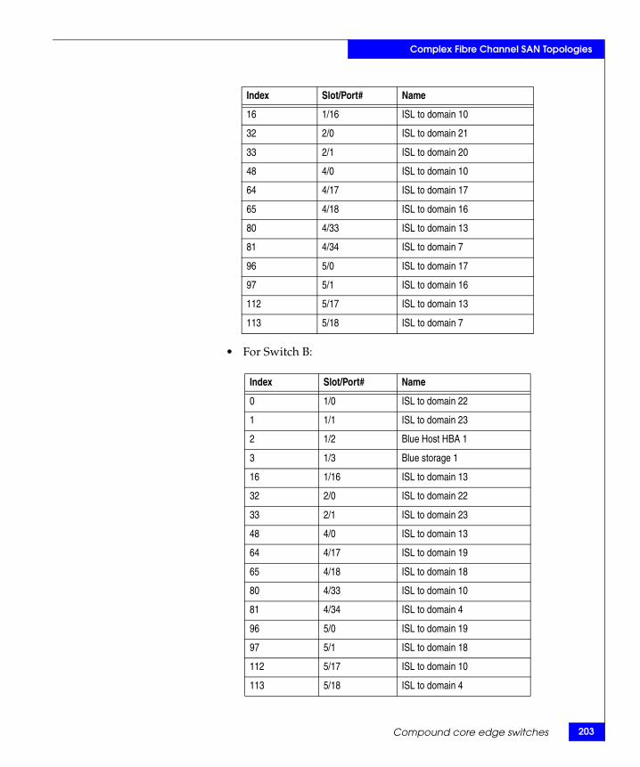
Complex Fibre Channel SAN Topologies
• For Switch B:
16 1/16 ISL to domain 10
32 2/0 ISL to domain 21
33 2/1 ISL to domain 20
48 4/0 ISL to domain 10
64 4/17 ISL to domain 17
65 4/18 ISL to domain 16
80 4/33 ISL to domain 13
81 4/34 ISL to domain 7
96 5/0 ISL to domain 17
97 5/1 ISL to domain 16
112 5/17 ISL to domain 13
113 5/18 ISL to domain 7
Index Slot/Port# Name
Index Slot/Port# Name
0 1/0 ISL to domain 22
1 1/1 ISL to domain 23
2 1/2 Blue Host HBA 1
3 1/3 Blue storage 1
16 1/16 ISL to domain 13
32 2/0 ISL to domain 22
33 2/1 ISL to domain 23
48 4/0 ISL to domain 13
64 4/17 ISL to domain 19
65 4/18 ISL to domain 18
80 4/33 ISL to domain 10
81 4/34 ISL to domain 4
96 5/0 ISL to domain 19
97 5/1 ISL to domain 18
112 5/17 ISL to domain 10
113 5/18 ISL to domain 4
Compound core edge switches 203
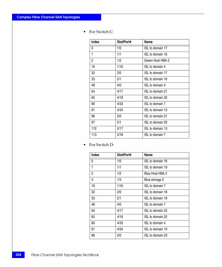
204
Complex Fibre Channel SAN Topologies
• For Switch C:
• For Switch D:
Index Slot/Port# Name
0 1/0 ISL to domain 17
1 1/1 ISL to domain 16
2 1/2 Green Host HBA 2
16 1/16 ISL to domain 4
32 2/0 ISL to domain 17
33 2/1 ISL to domain 16
48 4/0 ISL to domain 4
64 4/17 ISL to domain 21
65 4/18 ISL to domain 20
80 4/33 ISL to domain 7
81 4/34 ISL to domain 13
96 5/0 ISL to domain 21
97 5/1 ISL to domain 20
112 5/17 ISL to domain 13
113 5/18 ISL to domain 7
Index Slot/Port# Name
0 1/0 ISL to domain 18
1 1/1 ISL to domain 19
2 1/2 Blue Host HBA 2
3 1/3 Blue storage 2
16 1/16 ISL to domain 7
32 2/0 ISL to domain 18
33 2/1 ISL to domain 19
48 4/0 ISL to domain 7
64 4/17 ISL to domain 23
65 4/18 ISL to domain 22
80 4/33 ISL to domain 4
81 4/34 ISL to domain 10
96 5/0 ISL to domain 23
Fibre Channel SAN Topologies TechBook
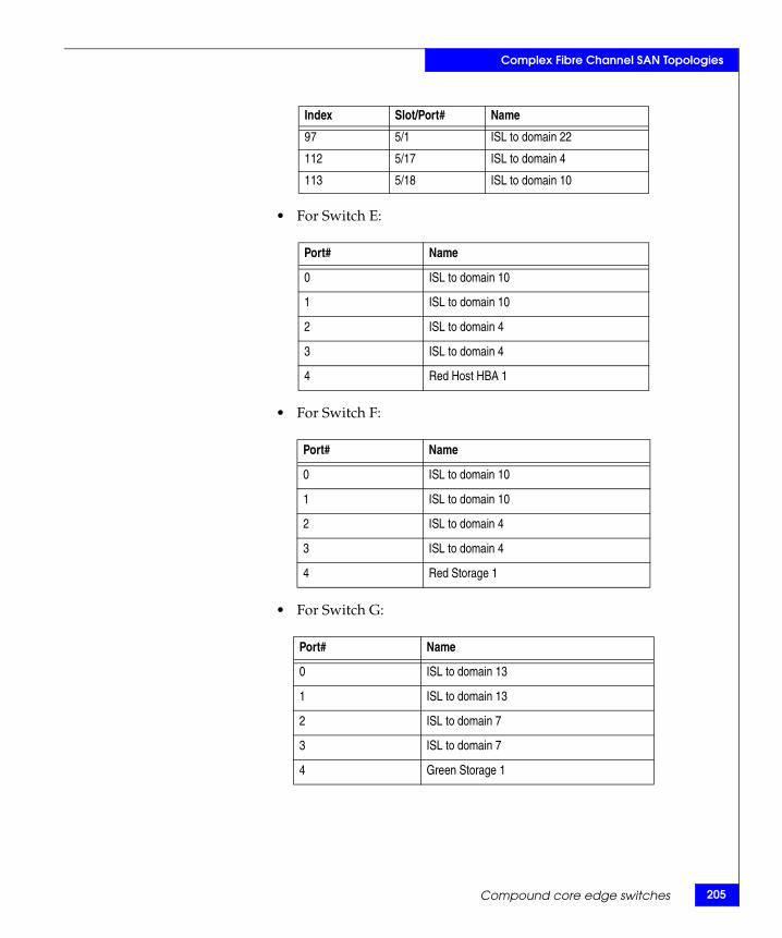
Complex Fibre Channel SAN Topologies
• For Switch E:
• For Switch F:
• For Switch G:
97 5/1 ISL to domain 22
112 5/17 ISL to domain 4
113 5/18 ISL to domain 10
Index Slot/Port# Name
Port# Name
0 ISL to domain 10
1 ISL to domain 10
2 ISL to domain 4
3 ISL to domain 4
4 Red Host HBA 1
Port# Name
0 ISL to domain 10
1 ISL to domain 10
2 ISL to domain 4
3 ISL to domain 4
4 Red Storage 1
Port# Name
0 ISL to domain 13
1 ISL to domain 13
2 ISL to domain 7
3 ISL to domain 7
4 Green Storage 1
Compound core edge switches 205
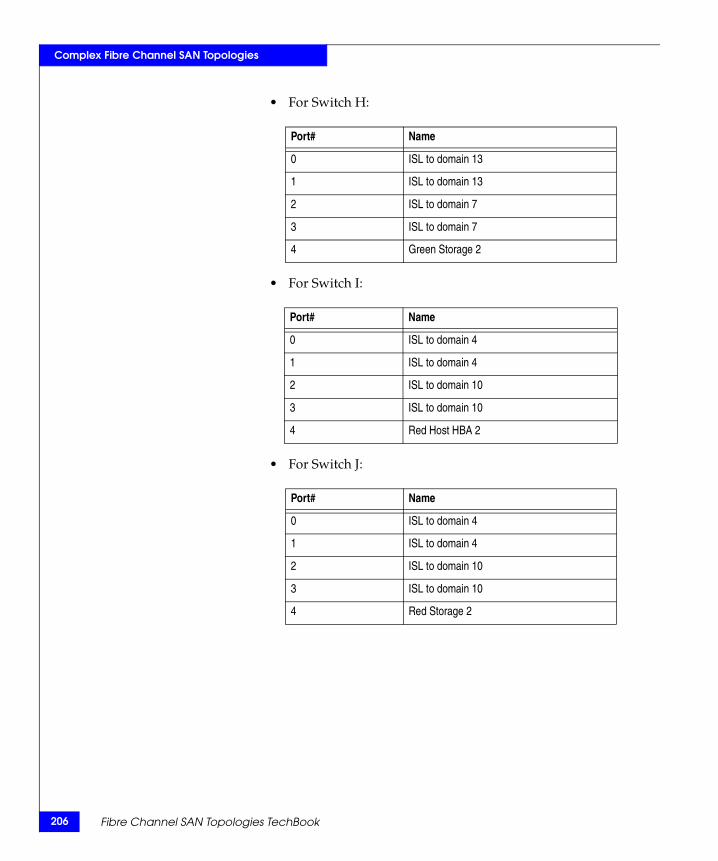
206
Complex Fibre Channel SAN Topologies
• For Switch H:
• For Switch I:
• For Switch J:
Port# Name
0 ISL to domain 13
1 ISL to domain 13
2 ISL to domain 7
3 ISL to domain 7
4 Green Storage 2
Port# Name
0 ISL to domain 4
1 ISL to domain 4
2 ISL to domain 10
3 ISL to domain 10
4 Red Host HBA 2
Port# Name
0 ISL to domain 4
1 ISL to domain 4
2 ISL to domain 10
3 ISL to domain 10
4 Red Storage 2
Fibre Channel SAN Topologies TechBook

Complex Fibre Channel SAN Topologies
• For Switch K:
• For Switch L:
3. Verify port login status.
a. After all cables are connected, use the switchshow CLI command to verify all of the ports logged into the switch. The ports with ISLs must log in as E_Ports while the ports connected to the HBA or storage must log in as F_Ports.
Zone hosts and storageTo zone hosts and storage:
1. Using a web browser, enter the IP address of Switch A (172.23.199.4) in the URL/address field.
2. Enter username and password at the prompt.
3. Click the Zone Admin icon in the lower left corner at bottom of web page.
4. The Zone Admin pop-up window should appear. You may be asked for login credentials again.
5. Under the Alias tab, click New Alias. A Create New Alias window appears. Enter Red_HBA1 as the alias name.
Port# Name
0 ISL to domain 7
1 ISL to domain 7
2 ISL to domain 13
3 ISL to domain 13
4 Green Storage 4
Port# Name
0 ISL to domain 7
1 ISL to domain 7
2 ISL to domain 13
3 ISL to domain 13
4 Green Storage 3
Compound core edge switches 207
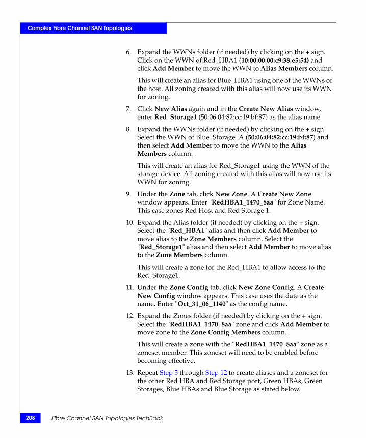
208
Complex Fibre Channel SAN Topologies
6. Expand the WWNs folder (if needed) by clicking on the + sign. Click on the WWN of Red_HBA1 (10:00:00:00:c9:38:e5:54) and click Add Member to move the WWN to Alias Members column.
This will create an alias for Blue_HBA1 using one of the WWNs of the host. All zoning created with this alias will now use its WWN for zoning.
7. Click New Alias again and in the Create New Alias window, enter Red_Storage1 (50:06:04:82:cc:19:bf:87) as the alias name.
8. Expand the WWNs folder (if needed) by clicking on the + sign. Select the WWN of Blue_Storage_A (50:06:04:82:cc:19:bf:87) and then select Add Member to move the WWN to the Alias Members column.
This will create an alias for Red_Storage1 using the WWN of the storage device. All zoning created with this alias will now use its WWN for zoning.
9. Under the Zone tab, click New Zone. A Create New Zone window appears. Enter "RedHBA1_1470_8aa" for Zone Name. This case zones Red Host and Red Storage 1.
10. Expand the Alias folder (if needed) by clicking on the + sign. Select the "Red_HBA1" alias and then click Add Member to move alias to the Zone Members column. Select the "Red_Storage1" alias and then select Add Member to move alias to the Zone Members column.
This will create a zone for the Red_HBA1 to allow access to the Red_Storage1.
11. Under the Zone Config tab, click New Zone Config. A Create New Config window appears. This case uses the date as the name. Enter "Oct_31_06_1140" as the config name.
12. Expand the Zones folder (if needed) by clicking on the + sign. Select the "RedHBA1_1470_8aa" zone and click Add Member to move zone to the Zone Config Members column.
This will create a zone with the "RedHBA1_1470_8aa" zone as a zoneset member. This zoneset will need to be enabled before becoming effective.
13. Repeat Step 5 through Step 12 to create aliases and a zoneset for the other Red HBA and Red Storage port, Green HBAs, Green Storages, Blue HBAs and Blue Storage as stated below.
Fibre Channel SAN Topologies TechBook
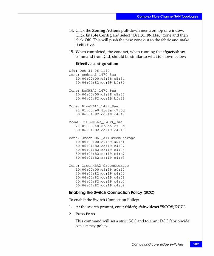
Complex Fibre Channel SAN Topologies
14. Click the Zoning Actions pull-down menu on top of window. Click Enable Config and select "Oct_31_06_1140" zone and then click OK. This will push the new zone out to the fabric and make it effective.
15. When completed, the zone set, when running the cfgactvshow command from CLI, should be similar to what is shown below:
Effective configuration:
Cfg: Oct_31_06_1140Zone: RedHBA1_1470_8aa
10:00:00:00:c9:38:e5:5450:06:04:82:cc:19:bf:87
Zone: RedHBA2_1470_9aa10:00:00:00:c9:38:e5:5550:06:04:82:cc:19:bf:88
Zone: BlueHBA1_1489_8aa21:01:00:e0:8b:8a:c7:6d50:06:04:82:cc:19:c4:47
Zone: BlueHBA2_1489_9aa21:01:00:e0:8b:aa:c7:6d50:06:04:82:cc:19:c4:48
Zone: GreenHBA1_AllGreenStorage10:00:00:00:c9:39:a0:5150:06:04:82:cc:19:c4:0750:06:04:82:cc:19:c4:0850:06:04:82:cc:19:c4:c750:06:04:82:cc:19:c4:c8
Zone: GreenHBA2_GreenStorage10:00:00:00:c9:39:a0:5250:06:04:82:cc:19:c4:0750:06:04:82:cc:19:c4:0850:06:04:82:cc:19:c4:c750:06:04:82:cc:19:c4:c8
Enabling the Switch Connection Policy (SCC)
To enable the Switch Connection Policy:
1. At the switch prompt, enter fddcfg -fabwideset "SCC:S;DCC".
2. Press Enter.
This command will set a strict SCC and tolerant DCC fabric-wide consistency policy.
Compound core edge switches 209
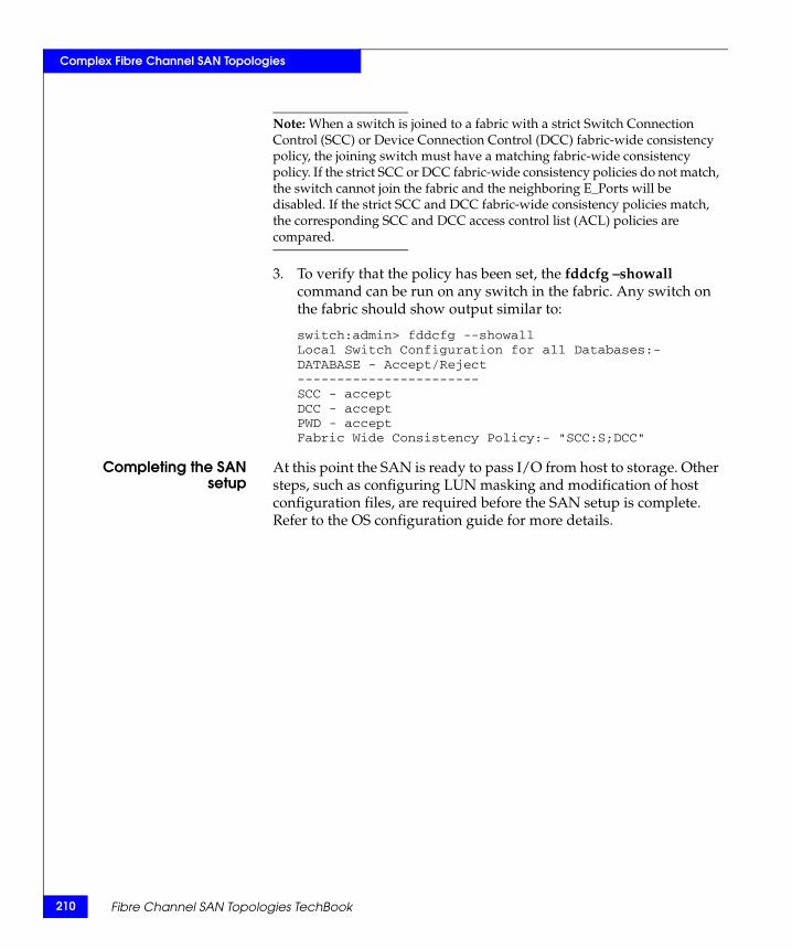
210
Complex Fibre Channel SAN Topologies
Note: When a switch is joined to a fabric with a strict Switch Connection Control (SCC) or Device Connection Control (DCC) fabric-wide consistency policy, the joining switch must have a matching fabric-wide consistency policy. If the strict SCC or DCC fabric-wide consistency policies do not match, the switch cannot join the fabric and the neighboring E_Ports will be disabled. If the strict SCC and DCC fabric-wide consistency policies match, the corresponding SCC and DCC access control list (ACL) policies are compared.
3. To verify that the policy has been set, the fddcfg –showall command can be run on any switch in the fabric. Any switch on the fabric should show output similar to:
switch:admin> fddcfg --showallLocal Switch Configuration for all Databases:-DATABASE - Accept/Reject-----------------------SCC - acceptDCC - acceptPWD - acceptFabric Wide Consistency Policy:- "SCC:S;DCC"
Completing the SANsetup
At this point the SAN is ready to pass I/O from host to storage. Other steps, such as configuring LUN masking and modification of host configuration files, are required before the SAN setup is complete. Refer to the OS configuration guide for more details.
Fibre Channel SAN Topologies TechBook
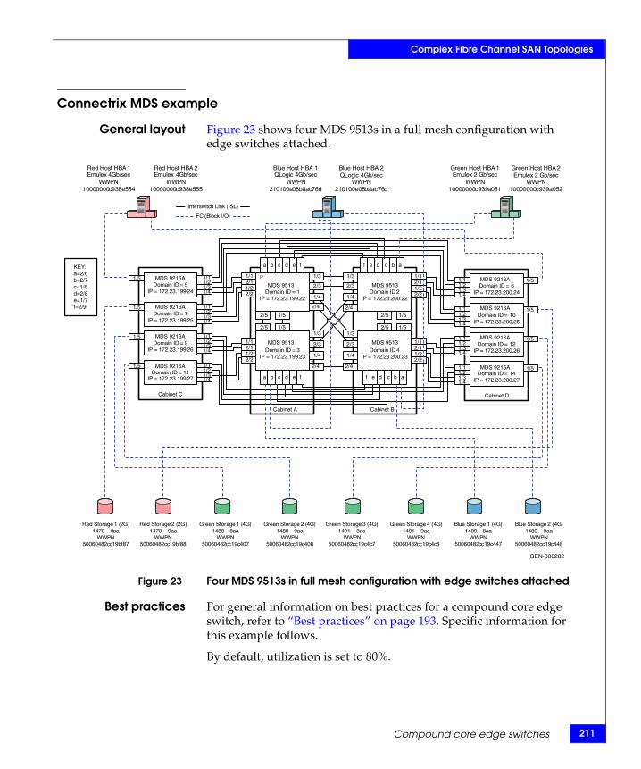
Complex Fibre Channel SAN Topologies
Connectrix MDS example
General layout Figure 23 shows four MDS 9513s in a full mesh configuration with edge switches attached.
Figure 23 Four MDS 9513s in full mesh configuration with edge switches attached
Best practices For general information on best practices for a compound core edge switch, refer to “Best practices” on page 193. Specific information for this example follows.
By default, utilization is set to 80%.
MDS 9513Domain ID = 1
IP = 172.23.199.22
Domain ID = 3IP = 172.23.199.23
Domain ID 4IP = 172.23.200.23
Domain ID 2IP = 172.23.200.22
FC (Block I/O
Interswitch Link (ISL
)
)
Cabinet A Cabinet B
Red Host HBA 1Emulex 4Gb/sec
WWPN10000000c938e554
Red Host HBA 2Emulex 4Gb/sec
WWPN10000000c938e555
Green Host HBA 1Emulex 2 Gb/sec
WWPN10000000c939a051
Green Host HBA 2Emulex 2 Gb/sec
WWPN10000000c939a052
Blue Host HBA 1QLogic 4Gb/sec
WWPN210100e08b8ac76d
Blue Host HBA 2QLogic 4Gb/sec
WWPN210100e08baac76d
Red Storage 2 (2G)1470 – 9aa
WWPN50060482cc19bf88
Red Storage 1 (2G)1470 – 8aa
WWPN50060482cc19bf87
Green Storage 1 (4G)1488 – 8aa
WWPN50060482cc19c407
Green Storage 2 (4G)1488 – 9aa
WWPN50060482cc19c408
Blue Storage 1 (4G)1489 – 8aa
WWPN50060482cc19c447
Blue Storage 2 (4G)1489 – 9aa
WWPN50060482cc19c448
Green Storage 3 (4G)1491 – 8aa
WWPN50060482cc19c4c7
Green Storage 4 (4G)1491 – 9aa
WWPN50060482cc19c4c8
1/3
2/3
2/5 1/5
2/5 1/5
1/4
2/4
P
Cabinet C
MDS 9216ADomain ID = 5
IP = 172.23.199.24
Domain ID = 7IP = 172.23.199.25
Domain ID = 9IP = 172.23.199.26
Domain ID = 11IP = 172.23.199.27
Cabinet D
Domain ID = 6IP = 172.23.200.24
Domain ID = 10IP = 172.23.200.25
Domain ID = 12IP = 172.23.200.26
Domain ID = 14IP = 172.23.200.27
2/11/1
1/22/2
a cb d e f
a cb d e f
ac bdef
ac bdef
1/5
GEN-000282
MDS 9216A
MDS 9216A
MDS 9216A
MDS 9216A
MDS 9216A
MDS 9216A
MDS 9216A
MDS 9513
MDS 9513
MDS 9513
KEY:a=2/6b=2/7c=1/6d=2/8e=1/7f=2/9 1/5
1/5
1/5
1/5
1/5
1/5
1/5
1/21/1
1/31/4
1/21/1
1/31/4
1/21/1
1/31/4
1/3
2/3
1/4
2/4
1/3
2/3
1/4
2/4
1/3
2/3
1/4
2/4
2/11/1
1/22/2
2/11/1
1/22/2
2/11/1
1/22/2
2/5 1/5
2/5 1/5
1/21/1
1/31/4
1/21/1
1/31/4
1/21/1
1/31/4
1/21/1
1/31/4
1/21/1
1/31/4
Compound core edge switches 211
212
Complex Fibre Channel SAN Topologies
Host and storagelayout
For general information on host and storage layout a compound core edge switch, refer to “Host and storage layout” on page 193. Specific information for this example follows.
Line Rate Cards have no special considerations. Over-subscribed cards should be used for hosts only.
Switch and fabricmanagement
For general information on switch and fabric management a compound core edge switch, refer to “Switch and fabric management” on page 193. Specific information for this example follows.
Cisco Fabric Manager can be used for complex fabrics.
Security For general information on security a compound core edge switch, refer to “Security” on page 193. Specific information for this example follows.
Enable switch and Port Binding for security.
Setting up thistopology
Assumptions specific to this case study:
◆ The switches are installed in an EMC-supplied cabinet.
• For installation instructions, see Connectrix EC-1500 Cabinet Installation and Setup Manual which can be accessed from Powerlink.
◆ The proper power receptacles have been provided by the customer.
• For switch power requirements, refer to refer to EMC Connectrix SAN Products Data Reference Manual, available through the E-Lab Interoperability Navigator, Topology Resource Center tab, at http://elabnavigator.EMC.com.
• For Cabinet power requirements, refer to Connectrix EC-1500 Cabinet Installation and Setup Manual, which can be accessed from Powerlink.
◆ The switches have not been connected to the power source and are not powered on.
◆ Network drops, IP addresses, subnet mask, and gateway have been provided by the customer.
For switch or cabinet network requirements, refer to refer to EMC Connectrix SAN Products Data Reference Manual, available through the E-Lab Interoperability Navigator, Topology Resource Center tab, at http://elabnavigator.EMC.com.
Fibre Channel SAN Topologies TechBook
Complex Fibre Channel SAN Topologies
Note: Connectrix MDS switches can be directly connected to the customer’s LAN. The switches can be placed on either a public or private network. There are advantages in both configurations. For more information, refer to refer to "Public versus private" in the Networked Storage Concepts and Protocols TechBook, available through the E-Lab Interoperability Navigator, Topology Resource Center tab, at http://elabnavigator.EMC.com.
This example assumes that the customer has provided us with two Ethernet cables and that one of them is on the 172.23.199.x network and that the other is connected to the 172.23.200.x network.
◆ The proper number of line cards have been installed into the Connectrix MDS 9513s.
For help in determining how many ports are required, refer to "Determining customer requirements" in the Networked Storage Concepts and Protocols TechBook, available through the E-Lab Interoperability Navigator, Topology Resource Center tab, at http://elabnavigator.EMC.com.
◆ License keys have been obtained.
• Go to the URL listed on the transaction code certificate that shipped with the product to get the license key.
◆ A laptop, connected to a Connectrix MDS serial port, is used to configure the IP addresses of the switches.
◆ The customer has provided a temporary password that is used as the default password when configuring the IP address.
◆ Cisco CLI, Fabric Manager, and Device Manager are used.
Configure the IP address
To configure the IP address:
1. Power up the cabinet by connecting the power cords to the power receptacles provided by the customer.
2. Select one of the switches to configure and set the IP to 172.23.199.22.
3. Supply a network connection to the appropriate subnet.
4. Using an RS232 serial cable, connect to the serial port of the switch with a baud rate of 9600, 8 data bits, no parity, 1 stop bit and no flow control.
Compound core edge switches 213
214
Complex Fibre Channel SAN Topologies
The login prompt should display.
5. Log in the first time with a username admin and password admin.
You should be prompted to supply a new strong password for CLI user admin.
6. For this example, select no when prompted to run setup.
Note: This example starts with the switch that will have a Domain ID of 1 and an IP address of 172.23.199.22.
CLI commands to configure the IP and gateway
◆ Switch# config terminal
Enter configuration commands, one per line.
Switch(config)# interface mgmt 0
Switch(config-if)#IP address 172.23.199.22 255.255.255.0
End with CNTL/Z.
◆ Switch# config terminal
Enter configuration commands, one per line.
Switch(config)# ip default-gateway 172.23.199.2
End with CNTL/Z.
To authorize access on a switch for Device and Fabric Manager, run this command on every switch while supplying a username (nnn) and password (ppp):
◆ Switch#conf t
Switch(config)# snmp-server user nnn network-admin auth md5 ppp
Switch(config)#end
Switch# copy running-config startup-config
Switch# exit
Configure the IP addresses of the switches in the cabinet
To configure the IP address of the switches in the other cabinet:
Follow Step 4 through Step 6 in “Configure the IP address” on page 213.
Fibre Channel SAN Topologies TechBook
Complex Fibre Channel SAN Topologies
Use the IP addresses found in Figure 18 on page 151 with subnet mask (255.255.255.0), and gateway (172.23.199.2 and 172.23.200.2).
Configure the rest of the switch IP addresses in the cabinet
To configure the next switch, follow Step 4 through Step 6 in “Configure the IP address” on page 213.
Use the IP address of (172.23.199.23), subnet mask (255.255.255.0), and gateway (172.23.199.2).
Install Fabric Manager and Device Manager
To install Fabric Manager and Device Manager:
1. Open your web browser.
2. Enter the IP address of the switch into the address bar.
3. Follow the prompts and accept all defaults to install both Fabric Manager and Device Manager.
Configure a VSAN followed by a domain
To configure a VSAN:
1. Open the Device Manager for the switch with an IP address of 172.23.199.22.
2. Open the VSAN dialog box by selecting the VSAN menu item.
3. Click Create.
4. Enter the value 100 in the VSAN ID field.
5. Set the VSAN Name to “Red_Vsan_100”.
6. Use the default interop mode.
7. Click Create.
8. Enter the value 200 in the VSAN ID field.
9. Set the next VSAN Name to be “Green_Vsan_200”.
10. Click Create.
11. Enter the value 300 in the VSAN ID field.
12. Set the next VSAN Name to “Blue_VSAN_300”.
13. Click Create, and then click Close.
Compound core edge switches 215
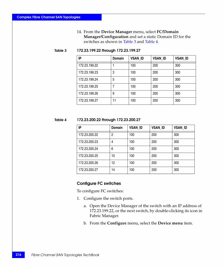
216
Complex Fibre Channel SAN Topologies
14. From the Device Manager menu, select FC/Domain Manager/Configuration and set a static Domain ID for the switches as shown in Table 3 and Table 4.
Configure FC switches
To configure FC switches:
1. Configure the switch ports.
a. Open the Device Manager of the switch with an IP address of 172.23.199.22, or the next switch, by double-clicking its icon in Fabric Manager.
b. From the Configure menu, select the Device menu item.
Table 3 172.23.199.22 through 172.23.199.27
IP Domain VSAN_ID VSAN_ID VSAN_ID
172.23.199.22 1 100 200 300
172.23.199.23 3 100 200 300
172.23.199.24 5 100 200 300
172.23.199.25 7 100 200 300
172.23.199.26 9 100 200 300
172.23.199.27 11 100 200 300
Table 4 172.23.200.22 through 172.23.200.27
IP Domain VSAN_ID VSAN_ID VSAN_ID
172.23.200.22 2 100 200 300
172.23.200.23 4 100 200 300
172.23.200.24 6 100 200 300
172.23.200.25 10 100 200 300
172.23.200.26 12 100 200 300
172.23.200.27 14 100 200 300
Fibre Channel SAN Topologies TechBook
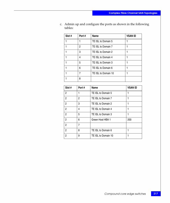
Complex Fibre Channel SAN Topologies
c. Admin up and configure the ports as shown in the following tables:
Slot # Port # Name VSAN ID
1 1 TE ISL to Domain 5 1
1 2 TE ISL to Domain 7 1
1 3 TE ISL to Domain 2 1
1 4 TE ISL to Domain 4 1
1 5 TE ISL to Domain 3 1
1 6 TE ISL to Domain 6 1
1 7 TE ISL to Domain 10 1
1 8
Slot # Port # Name VSAN ID
2 1 TE ISL to Domain 5 1
2 2 TE ISL to Domain 7 1
2 3 TE ISL to Domain 2 1
2 4 TE ISL to Domain 4 1
2 5 TE ISL to Domain 3 1
2 6 Green Host HBA 1 200
2 7
2 8 TE ISL to Domain 6 1
2 9 TE ISL to Domain 10 1
Compound core edge switches 217
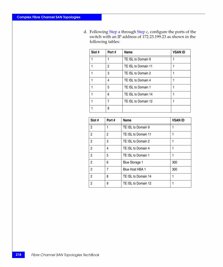
218
Complex Fibre Channel SAN Topologies
d. Following Step a through Step c, configure the ports of the switch with an IP address of 172.23.199.23 as shown in the following tables:
Slot # Port # Name VSAN ID
1 1 TE ISL to Domain 9 1
1 2 TE ISL to Domain 11 1
1 3 TE ISL to Domain 2 1
1 4 TE ISL to Domain 4 1
1 5 TE ISL to Domain 1 1
1 6 TE ISL to Domain 14 1
1 7 TE ISL to Domain 12 1
1 8
Slot # Port # Name VSAN ID
2 1 TE ISL to Domain 9 1
2 2 TE ISL to Domain 11 1
2 3 TE ISL to Domain 2 1
2 4 TE ISL to Domain 4 1
2 5 TE ISL to Domain 1 1
2 6 Blue Storage 1 300
2 7 Blue Host HBA 1 300
2 8 TE ISL to Domain 14 1
2 9 TE ISL to Domain 12 1
Fibre Channel SAN Topologies TechBook
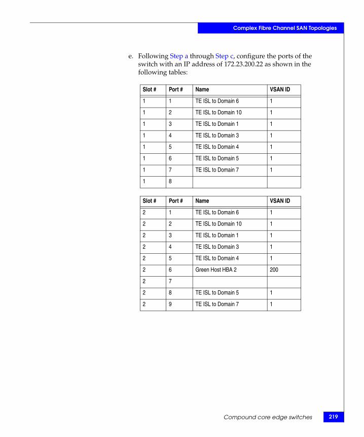
Complex Fibre Channel SAN Topologies
e. Following Step a through Step c, configure the ports of the switch with an IP address of 172.23.200.22 as shown in the following tables:
Slot # Port # Name VSAN ID
1 1 TE ISL to Domain 6 1
1 2 TE ISL to Domain 10 1
1 3 TE ISL to Domain 1 1
1 4 TE ISL to Domain 3 1
1 5 TE ISL to Domain 4 1
1 6 TE ISL to Domain 5 1
1 7 TE ISL to Domain 7 1
1 8
Slot # Port # Name VSAN ID
2 1 TE ISL to Domain 6 1
2 2 TE ISL to Domain 10 1
2 3 TE ISL to Domain 1 1
2 4 TE ISL to Domain 3 1
2 5 TE ISL to Domain 4 1
2 6 Green Host HBA 2 200
2 7
2 8 TE ISL to Domain 5 1
2 9 TE ISL to Domain 7 1
Compound core edge switches 219
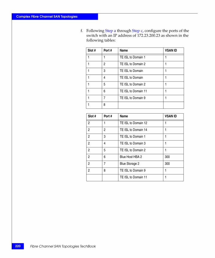
220
Complex Fibre Channel SAN Topologies
f. Following Step a through Step c, configure the ports of the switch with an IP address of 172.23.200.23 as shown in the following tables:
Slot # Port # Name VSAN ID
1 1 TE ISL to Domain 1 1
1 2 TE ISL to Domain 2 1
1 3 TE ISL to Domain 1
1 4 TE ISL to Domain 1
1 5 TE ISL to Domain 2 1
1 6 TE ISL to Domain 11 1
1 7 TE ISL to Domain 9 1
1 8
Slot # Port # Name VSAN ID
2 1 TE ISL to Domain 12 1
2 2 TE ISL to Domain 14 1
2 3 TE ISL to Domain 1 1
2 4 TE ISL to Domain 3 1
2 5 TE ISL to Domain 2 1
2 6 Blue Host HBA 2 300
2 7 Blue Storage 2 300
2 8 TE ISL to Domain 9 1
TE ISL to Domain 11 1
Fibre Channel SAN Topologies TechBook
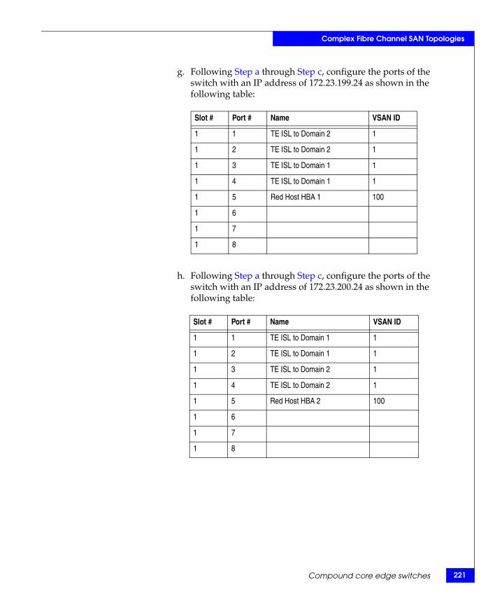
Complex Fibre Channel SAN Topologies
g. Following Step a through Step c, configure the ports of the switch with an IP address of 172.23.199.24 as shown in the following table:
h. Following Step a through Step c, configure the ports of the switch with an IP address of 172.23.200.24 as shown in the following table:
Slot # Port # Name VSAN ID
1 1 TE ISL to Domain 2 1
1 2 TE ISL to Domain 2 1
1 3 TE ISL to Domain 1 1
1 4 TE ISL to Domain 1 1
1 5 Red Host HBA 1 100
1 6
1 7
1 8
Slot # Port # Name VSAN ID
1 1 TE ISL to Domain 1 1
1 2 TE ISL to Domain 1 1
1 3 TE ISL to Domain 2 1
1 4 TE ISL to Domain 2 1
1 5 Red Host HBA 2 100
1 6
1 7
1 8
Compound core edge switches 221
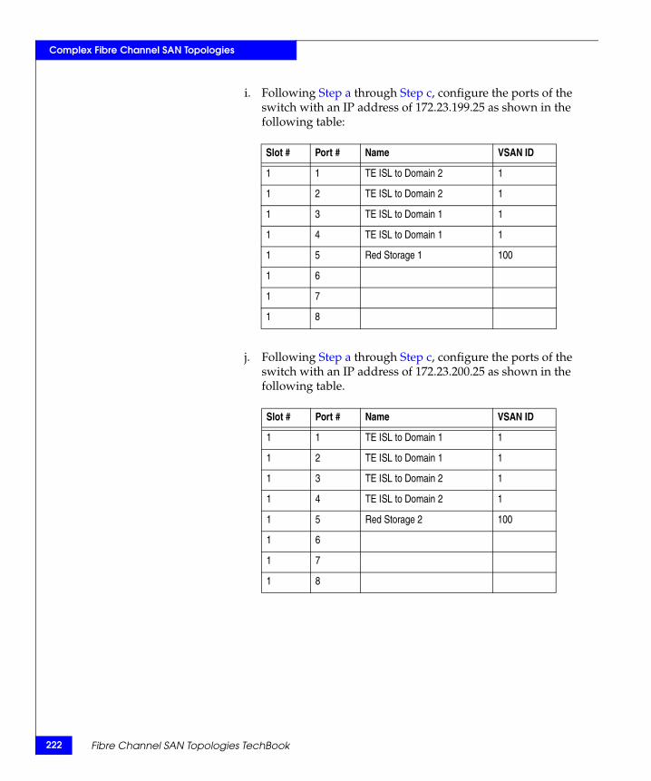
222
Complex Fibre Channel SAN Topologies
i. Following Step a through Step c, configure the ports of the switch with an IP address of 172.23.199.25 as shown in the following table:
j. Following Step a through Step c, configure the ports of the switch with an IP address of 172.23.200.25 as shown in the following table.
Slot # Port # Name VSAN ID
1 1 TE ISL to Domain 2 1
1 2 TE ISL to Domain 2 1
1 3 TE ISL to Domain 1 1
1 4 TE ISL to Domain 1 1
1 5 Red Storage 1 100
1 6
1 7
1 8
Slot # Port # Name VSAN ID
1 1 TE ISL to Domain 1 1
1 2 TE ISL to Domain 1 1
1 3 TE ISL to Domain 2 1
1 4 TE ISL to Domain 2 1
1 5 Red Storage 2 100
1 6
1 7
1 8
Fibre Channel SAN Topologies TechBook

Complex Fibre Channel SAN Topologies
k. Following Step a through Step c, configure the ports of the switch with an IP address of 172.23.199.26 as shown in the following table:
l. Following Step a through Step c, configure the ports of the switch with an IP address of 172.23.200.26 as shown in the following table:
Slot # Port # Name VSAN ID
1 1 TE ISL to Domain 4 1
1 2 TE ISL to Domain 4 1
1 3 TE ISL to Domain 3 1
1 4 TE ISL to Domain 4 1
1 5 Green Storage 1 200
1 6
1 7
1 8
Slot # Port # Name VSAN ID
1 1 TE ISL to Domain 3 1
1 2 TE ISL to Domain 3 1
1 3 TE ISL to Domain 4 1
1 4 TE ISL to Domain 4 1
1 5 Green Storage 4 1
1 6
1 7
1 8
Compound core edge switches 223
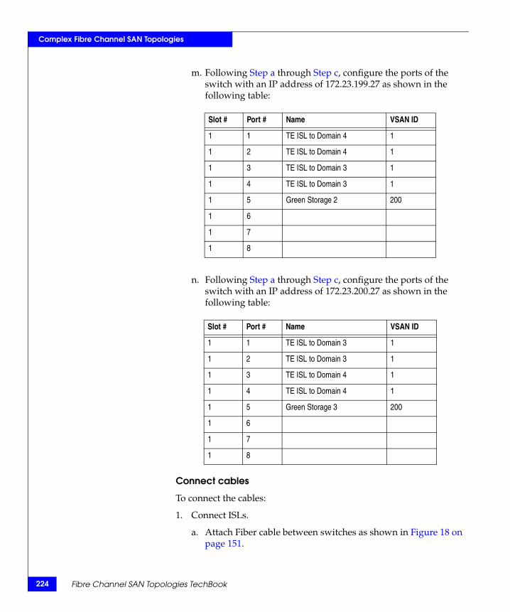
224
Complex Fibre Channel SAN Topologies
m. Following Step a through Step c, configure the ports of the switch with an IP address of 172.23.199.27 as shown in the following table:
n. Following Step a through Step c, configure the ports of the switch with an IP address of 172.23.200.27 as shown in the following table:
Connect cables
To connect the cables:
1. Connect ISLs.
a. Attach Fiber cable between switches as shown in Figure 18 on page 151.
Slot # Port # Name VSAN ID
1 1 TE ISL to Domain 4 1
1 2 TE ISL to Domain 4 1
1 3 TE ISL to Domain 3 1
1 4 TE ISL to Domain 3 1
1 5 Green Storage 2 200
1 6
1 7
1 8
Slot # Port # Name VSAN ID
1 1 TE ISL to Domain 3 1
1 2 TE ISL to Domain 3 1
1 3 TE ISL to Domain 4 1
1 4 TE ISL to Domain 4 1
1 5 Green Storage 3 200
1 6
1 7
1 8
Fibre Channel SAN Topologies TechBook
Complex Fibre Channel SAN Topologies
b. After all cables are connected, use Fabric Manager to verify that all ISL connections are up.
c. Re-arrange icons to accurately reflect the switch configuration.
2. Connect host and storage ports.
a. Attach fiber cable between the switches and N_Ports.
Configure domains
Using Fabric Manager set the static Domain IDs for each VSAN and switch.
Zone hosts and storage
To zone hosts and storage:
1. Open the Zoning dialog box in Connectrix Manager by right-clicking the appropriate fabric topology and selecting the Zoning menu item.
2. Create a zone by clicking New Zone under the Zones Tree.
3. Provide a descriptive name for the zone. This example zones “Red host HBA 1” and “Red Storage 1”. Type “RedHBA1_1470_8aa” and press Enter.
4. Select “Red Host HBA 1” (WWPN 10000000c938e554) in the potential zone members list.
5. Click the right-pointing arrow on the divider between the potential members list, and the zones list to add the HBA to the zone.
6. Select “Red Storage 1” (WWPN 50060482cc19bf87) in the potential zone members list.
7. Click the right- pointing arrow on the divider between the potential members list and the zones list to add the storage port to the zone.
8. Repeat Step 2 through Step 6 for all host and storage pairs in the environment.
9. Create a zone set by clicking New Set under the Zone Sets Tree.
10. Provide a descriptive name for the zone set as shown in the example following Step 12.
Compound core edge switches 225
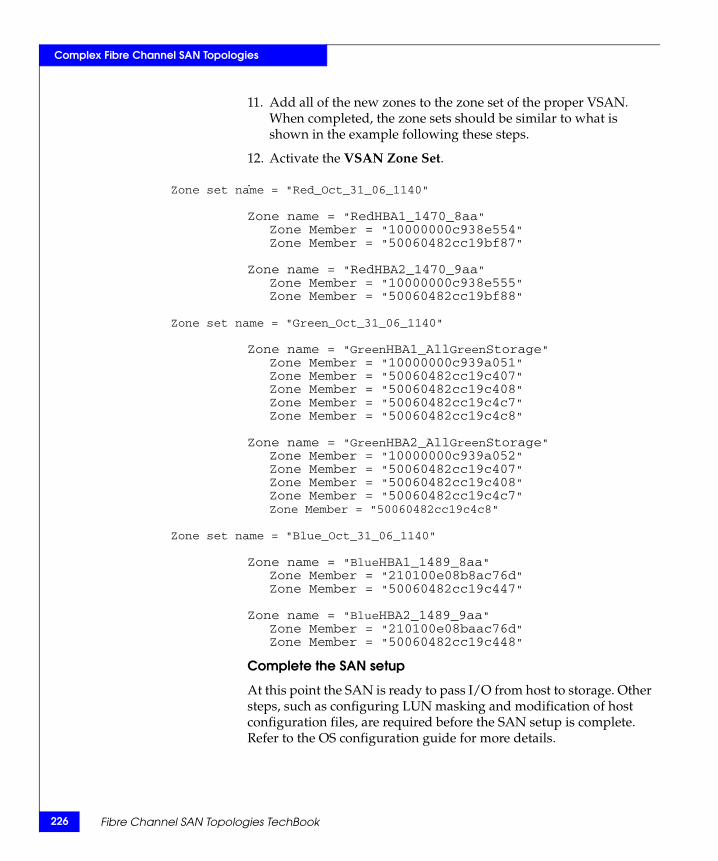
226
Complex Fibre Channel SAN Topologies
11. Add all of the new zones to the zone set of the proper VSAN. When completed, the zone sets should be similar to what is shown in the example following these steps.
12. Activate the VSAN Zone Set.
.Zone set name = "Red_Oct_31_06_1140"
Zone name = "RedHBA1_1470_8aa"Zone Member = "10000000c938e554"Zone Member = "50060482cc19bf87"
Zone name = "RedHBA2_1470_9aa"Zone Member = "10000000c938e555"Zone Member = "50060482cc19bf88"
Zone set name = "Green_Oct_31_06_1140"
Zone name = "GreenHBA1_AllGreenStorage"Zone Member = "10000000c939a051"Zone Member = "50060482cc19c407"Zone Member = "50060482cc19c408"Zone Member = "50060482cc19c4c7"Zone Member = "50060482cc19c4c8"
Zone name = "GreenHBA2_AllGreenStorage"Zone Member = "10000000c939a052"Zone Member = "50060482cc19c407"Zone Member = "50060482cc19c408"Zone Member = "50060482cc19c4c7"Zone Member = "50060482cc19c4c8"
Zone set name = "Blue_Oct_31_06_1140"
Zone name = "BlueHBA1_1489_8aa"Zone Member = "210100e08b8ac76d"Zone Member = "50060482cc19c447"
Zone name = "BlueHBA2_1489_9aa"Zone Member = "210100e08baac76d"Zone Member = "50060482cc19c448"
Complete the SAN setup
At this point the SAN is ready to pass I/O from host to storage. Other steps, such as configuring LUN masking and modification of host configuration files, are required before the SAN setup is complete. Refer to the OS configuration guide for more details.
Fibre Channel SAN Topologies TechBook

Complex Fibre Channel SAN Topologies
Connectrix M example
General layout Figure 24 shows four ED-10000Ms in a full mesh configuration with edge switches attached.
Figure 24 Four ED-10000Ms in full mesh configuration with edge switches attached
Note: Any director class product such as the ED-10000M, ED-140M, or ED-64M can be used in the core of this fabric. All Director and switch class products can be used as edge switches.
ED-10000MDomain ID = 1
IP = 172.23.199.22
ED-10000MDomain ID = 3
IP = 172.23.199.23
ED-10000MDomain ID 4
IP = 172.23.200.23
ED-10000MDomain ID 2
IP = 172.23.200.22
FC (Block I/O
Interswitch Link (ISL
)
)
Cabinet A Cabinet B
Red Host HBA 1Emulex 4Gb/sec
WWPN10000000c938e554
Red Host HBA 2Emulex 4Gb/sec
WWPN10000000c938e555
Green Host HBA 1Emulex 2 Gb/sec
WWPN10000000c939a051
Green Host HBA 2Emulex 2 Gb/sec
WWPN10000000c939a052
Blue Host HBA 1QLogic 4Gb/sec
WWPN210100e08b8ac76d
Blue Host HBA 2QLogic 4Gb/sec
WWPN210100e08baac76d
Red Storage 2 (2G)1470 – 9aa
WWPN50060482cc19bf88
Red Storage 1 (2G)1470 – 8aa
WWPN50060482cc19bf87
Green Storage 1 (4G)1488 – 8aa
WWPN50060482cc19c407
Green Storage 2 (4G)1488 – 9aa
WWPN50060482cc19c408
Blue Storage 1 (4G)1489 – 8aa
WWPN50060482cc19c447
Blue Storage 2 (4G)1489 – 9aa
WWPN50060482cc19c448
Green Storage 3 (4G)1491 – 8aa
WWPN50060482cc19c4c7
Green Storage 4 (4G)1491 – 9aa
WWPN50060482cc19c4c8
16 16
48 48
81 113 81 113
81 113
16
48
112
80
80
112
80
112
80
112
16
48
81 113
P
Cabinet C
DS-4700MDomain ID = 5
IP = 172.23.199.24
Domain ID = 7IP = 172.23.199.25
Domain ID = 9IP = 172.23.199.26
Domain ID = 11IP = 172.23.199.27
Cabinet D
Domain ID = 6IP = 172.23.200.24
Domain ID = 10IP = 172.23.200.25
Domain ID = 12IP = 172.23.200.26
Domain ID = 14IP = 172.23.200.27
10
23
6597
9664
6597
9664
10
23
10
23
10
23
10
23
6597
9664
6597
9664
10
23
10
23
10
23
0 32
1 33
2
0 32
1 33
3 23 2 33
1 32
0
2 33
1 32
0
4
4
4
4
4
4
4
4
GEN-000251
DS-4700M
DS-4700M
DS-4700M
DS-4700M
DS-4700M
DS-4700M
DS-4700M
Compound core edge switches 227
228
Complex Fibre Channel SAN Topologies
Best practices For general information on best practices for a compound core edge switch, refer to “Best practices” on page 193. Specific information for this example follows.
Host and storagelayout
The N_Port and E_Port connections on the ED-10000M were spread out over as many SPPe’s as possible. This was done to ensure fairness (refer to the "Connectrix ED-10000M" in the EMC Connectrix SAN Products Data Reference Manual, available through the E-Lab Interoperability Navigator, Topology Resource Center tab, at http://elabnavigator.EMC.com) and increase the reliability of the network by minimizing the impact that any single hardware failure would have. The N_Port and E_Port connections on the DS-4700Ms are attached to the chassis in order since there are no benefits to performance or reliability by spreading out the connections.
In both cases, an attempt has been made to connect ISLs to the same number port on both switch to help assist with troubleshooting should the need arise.
For general information on host and storage layout a compound core edge switch, refer to “Host and storage layout” on page 193.
Switch and fabricmanagement
Connectrix Manager will be used to configure the environment in this example. Using Connectrix Manager Basic or CLI in this example is not practical.
For general information on switch and fabric management a compound core edge switch, refer to “Switch and fabric management” on page 193.
Security For general information on security on a compound core edge switch, refer to “Security” on page 193. Specific information for this example follows.
At the end of this example, Fabric Binding and Switch Binding are enabled by turning on Enterprise Fabric Mode. For more information on Fabric Binding, refer to "Fabric Binding" in the Building Secure SANs TechBook, available through the E-Lab Interoperability Navigator, Topology Resource Center tab, at http://elabnavigator.EMC.com.
Fibre Channel SAN Topologies TechBook
Complex Fibre Channel SAN Topologies
Setting up thistopology
Assumptions specific to this case study:
◆ The switches are installed in an EMC-supplied cabinet.
• For installation instructions, see Connectrix EC-1500 Cabinet Installation and Setup Manual, which can be accessed from Powerlink.
◆ The proper power receptacles have been provided by the customer.
• For switch power requirements, refer to the EMC Connectrix SAN Products Data Reference Manual, available through the E-Lab Interoperability Navigator, Topology Resource Center tab, at http://elabnavigator.EMC.com.
• For cabinet power requirements, refer to Connectrix EC-1500 Cabinet Installation and Setup Manual, which can be accessed from Powerlink.
◆ The switches have not been connected to the power source and are not powered on.
Note: Connectrix M switches ship with a default IP address of 10.1.1.10. If all of the switches are powered on and connected to the hub in the switch cabinet, communication with the switch using the network interfaces is not possible and you must program the IP addresses using the serial port.
This section assumes that the serial port is not used and the IP addresses is programmed through the network interface.
◆ Network drops, IP addresses, subnet mask, and gateway were provided by the customer.
For switch or cabinet network requirements, refer to the EMC Connectrix SAN Products Data Reference Manual,available through the E-Lab Interoperability Navigator, Topology Resource Center tab, at http://elabnavigator.EMC.com.
Note: Connectrix M switches can be either attached to the Ethernet hub that comes with the cabinet, or directly connected to the customer LAN. In both cases, the switches can be placed on either a public or private network. There are advantages to both configurations. For more information, refer to "Public versus private" in the Networked Storage Concepts and Protocols TechBook, available through the E-Lab Interoperability Navigator, Topology Resource Center tab, at http://elabnavigator.EMC.com.
Compound core edge switches 229
230
Complex Fibre Channel SAN Topologies
This example assumes that the customer has provided us with two Ethernet cables and that one of them is on the 172.23.199.x network and that the other is connected to the 172.23.200.x network. All switches are connected to the Ethernet hubs in the cabinet.
◆ The proper number of LIMs have been installed into the ED-10000Ms.
• For help in determining how many ports are required, refer to "Determining customer requirements" in the Networked Storage Concepts and Protocols TechBook, available through the E-Lab Interoperability Navigator, Topology Resource Center tab, at http://elabnavigator.EMC.com.
◆ License keys have been obtained.
• Go to the URL listed on the transaction code certificate that shipped with the product to get the license key.
◆ A Service Processor is installed in at least one of the cabinets.
◆ The Service Processor is used to configure the IP addresses of the switches.
◆ One interface from the Service Processor is connected to the Ethernet hub and this interface has an IP address of 10.1.1.11. (Check Default on the SP image and use that value.)
◆ The customer has provided a temporary password that will be used as the default password when configuring the IP address.
◆ Connectrix Manager is used and the Connectrix Manager installation kit is available.
◆ Connectrix Manager is not already installed on the Service Processor.
◆ The customer has purchased the Security Center License.
Configure the IP addresses of the ED-10000Ms in cabinet A
To configure the IP address of the ED-10000Ms in cabinet A:
1. In the cabinet that contains the Service Processor, select one of the switches to configure.
Note: This example starts with the switch that has a Domain ID of 1 and an IP address of 172.23.199.22.
Fibre Channel SAN Topologies TechBook
Complex Fibre Channel SAN Topologies
2. Power up the cabinet by connecting the power cords to the power receptacles provided by the customer. This causes both the directors and the Service Processor to power up.
3. Log in to the Service Processor once it has powered up. The default username and password is administrator and password.
4. Perform the following steps to change a product IP address, subnet mask, or gateway address. An asynchronous RS-232 modem cable and maintenance terminal (desktop or notebook PC) with a Windows-based operating system and RS-232 serial communication software (such as ProComm Plus or HyperTerminal) are required.
Note: The Service Processor can be used for configuring the IP addresses through a serial cable.
a. Using a Phillips screwdriver, remove the protective cap from the 9-pin maintenance port. Connect one end of the RS-232 modem cable to the port.
b. Connect the other cable end to a 9-pin serial communication port (COM1 or COM2) at the rear of the maintenance terminal PC.
c. Power-on the maintenance terminal. At the Windows desktop, click Start. The Windows Workstation menu displays.
Note: The following steps describe changing network addresses using HyperTerminal serial communication software.
Compound core edge switches 231
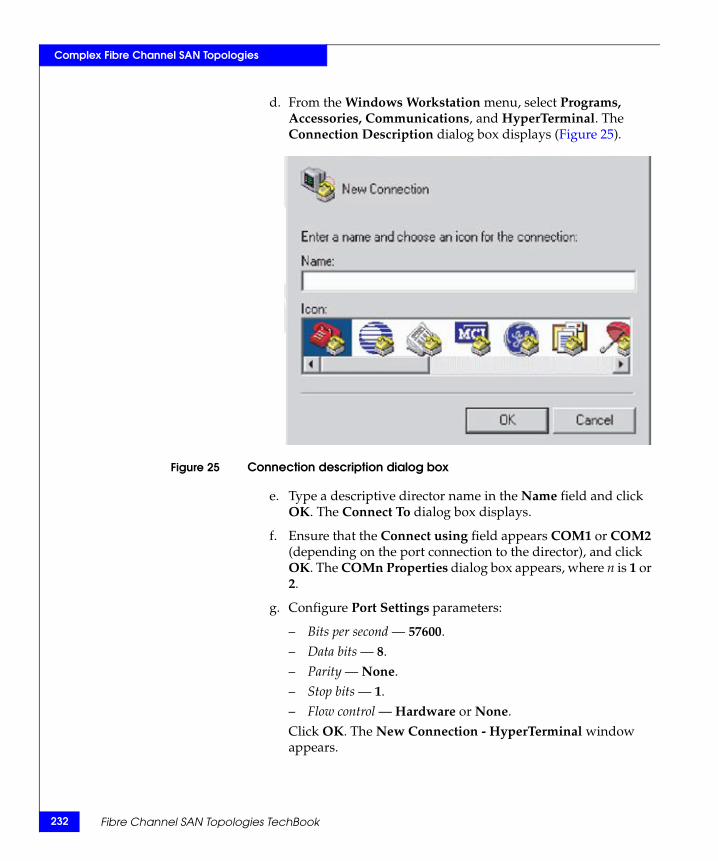
232
Complex Fibre Channel SAN Topologies
d. From the Windows Workstation menu, select Programs, Accessories, Communications, and HyperTerminal. The Connection Description dialog box displays (Figure 25).
Figure 25 Connection description dialog box
e. Type a descriptive director name in the Name field and click OK. The Connect To dialog box displays.
f. Ensure that the Connect using field appears COM1 or COM2 (depending on the port connection to the director), and click OK. The COMn Properties dialog box appears, where n is 1 or 2.
g. Configure Port Settings parameters:
– Bits per second — 57600.– Data bits — 8.– Parity — None.– Stop bits — 1.– Flow control — Hardware or None.Click OK. The New Connection - HyperTerminal window appears.
Fibre Channel SAN Topologies TechBook
Complex Fibre Channel SAN Topologies
h. At the EOS# prompt, type the user password (default is password) and press Enter. The password is case-sensitive. The New Connection - HyperTerminal window appears with software and hardware version information for the director.
i. At the EOS# prompt, type the system ip command and press Enter. The New Connection - HyperTerminal window appears with configuration information listed:
– MAC Address.– IP address (default is 10.1.1.10).
Note: IP address is the preinstalled IP address but may not be correct for your director. Consult your OEM provider for precise information about the IP address.
– Subnet Mask (default is 255.0.0.0).– Gateway Address (default is 0.0.0.0).Only the IP address, Subnet Mask, and Gateway Address fields are configurable.
j. Change the IP address, subnet mask, and gateway address as directed by the customer. To change the addresses, type the following and press Enter.
system ip xxx.xxx.xxx.xxx yyy.yyy.yyy.yyy zzz.zzz.zzz.zzz
The IP address is xxx.xxx.xxx.xxx, the subnet mask is yyy.yyy.yyy.yyy, and the gateway address is zzz.zzz.zzz.zzz, where the octets xxx, yyy, and zzz are decimals from zero through 255. If an address is to remain unchanged, type the current address in the respective field.
Configure the rest of the switch IP addresses in cabinet A
To configure the next switch in the cabinet, follow Step 4a through Step 4j, using the IP address of 172.23.199.23.
Configure the IP addresses of the ED-10000Ms in cabinet B
To configure the ED-10000Ms in the other cabinet, follow Step 4a through Step 4j, using the IP address of 172.23.200.22 for the top switch (Domain ID 2) and 172.23.200.23 for the bottom switch (Domain ID 4).
Compound core edge switches 233
234
Complex Fibre Channel SAN Topologies
Configure the IP addresses of the ED-4700Ms in cabinets C and D
Note: To configure the switch in the other cabinet, a cable can be connected between the two hubs to allow for communication between the service processor in one cabinet (cabinet A in our example), and the switches in the other cabinet (cabinet B in our example). This technique is used in this section.
1. Connect a straight through cable to port 24 on the cabinet B. Ensure that MDIX is set on port 24 by pushing the recessed MDI/MDIX button.
2. Connect the other end of cable connected to port 24 in Step 1 to any port other than 24 on the Ethernet hub in cabinet A.
Note: This example configures the switch with the IP address of 172.23.199.24 first.
3. Disconnect the network cables from the other switches in the cabinet. Failure to do so causes an IP address conflict when the cabinet is powered up.
Note: Cabinet D should not be powered up yet, but if it is, and a network cable is connected between the two hubs, remember that the network cables from the other switches must be disconnected to avoid running into duplicate IP address problems.
4. Power up cabinet C by connecting the power cords to the power receptacles provided by the customer. This causes the switches to power up.
5. Open a command prompt and ping the IP address of 10.1.1.10. If you get a response, continue at Step 6. If you do not get a response, you can either IML the switch by selecting the gray button on the CTP, or configure the IP address using the serial port.
Note: See the installation and service manuals for more information about configuring the IP address using the serial port.
6. Launch Internet Explorer and enter the IP address of 10.1.1.10, and then press Enter.. The Login banner appears.
7. Click Accept to display the Login dialog box.
Fibre Channel SAN Topologies TechBook
Complex Fibre Channel SAN Topologies
8. Enter the default username and password of Administrator and password, and then press Enter.
Note: It is strongly recommended that when prompted to change the password, you change it to a password provided by the customer.
9. Click Details in the Connectrix Manager Basic Topology view.
10. Navigate to the Network Configuration dialog box by clicking the Configure pull-down menu, and selecting switch and then Network.
11. Enter the IP address (172.23.199.24), subnet mask (255.255.255.0), and gateway (172.23.199.2), and then click OK.
Note: An error message appears stating Unable to display…. This appears because the IP address of the switch changed and you can no longer connect to the switch at its old IP address.
Configure the rest of the switch IP addresses in cabinet CTo configure the rest of the swtich IP addresses:
1. To configure the next switch in the cabinet, re-connect the network cables to the management port of the switch that will eventually have the IP address of 172.23.199.25, and then follow steps Step 5 through Step 11 in the previous section. Use the IP address of (172.23.199.25), subnet mask (255.255.255.0), and gateway (172.23.199.2).
2. Repeat this process for the other switches in cabinet C using IP addresses 172.23.199.26 and 172.23.199.27.
Configure the switch IP addresses in cabinet D
Follow the same process for configuring the switch IP addresses in cabinet D for cabinet C, but use the IP addresses of 172.23.200.24, 172.23.200.25, 172.23.200.26, and 172.23.200.27.
Install Connectrix Manager
Note: Refer to the EMC Connectrix Manager User Guide for complete installation instructions.
Compound core edge switches 235
236
Complex Fibre Channel SAN Topologies
To install Connectrix Manager:
1. Insert the Connectrix Manager installation CD into the CD-RW drive.
2. Browse to the CD-RW drive in Windows Explorer.
3. Locate, then double-click, the install.exe file. The installer appears. Typically, this file is located under the CtxMgr <version number> folder.
4. Accept all of the defaults by clicking Next and OK, when appropriate.
5. Click Done when the Installation Complete dialog box appears.
6. Click Next when the Welcome dialog box appears.
7. Accept the EULA terms, and then click Next.
8. At the Copy data and Settings dialog box, select No, then Next.
Note: "No" is selected in this step since this section assumes that this is a new installation.
9. Assign a Connectrix Manager 9.0 Server Name, and click Next.
This case uses CMServer.
10. Enter the serial number and license key in the fields provided in the Connectrix Manager 9.0 Server License dialog box.
• The serial number appears on the back of the Connectrix Manager installation CD case.
• To obtain a license key, locate the transaction code certificate and go to the URL listed.
a. Enter the serial number located on the back of the Connectrix Manager installation CD case.
b. In the Transaction Code fields, enter the transaction code(s) shipped with the software.
c. Click Next.
d. Confirm the existing and new features to be enabled.
e. Click Next.
The license key and all enabled features appear.
f. Retain a copy for your records.
Fibre Channel SAN Topologies TechBook
Complex Fibre Channel SAN Topologies
g. Enter this key into the License key field.
h. Click OK.
11. Once the installation is complete, log in to Connectrix Manager with the username of administrator and the password of password.
Note: Change this default as soon as possible. For this example, the username nnn and password nnn will be used.
Configure FC switches
To configure FC switches:
1. Set the switch name and Domain ID.
a. From Connectrix Manager, double-click the switch icon for the switch with an IP address of 172.23.199.22. The Element Manager appears.
b. Under Configure, select the Operating parameters menu item.
c. Click the Domain tab and ensure that the preferred Domain ID is set to the appropriate number (1 in this example).
d. Select the insistent Domain ID checkbox to enable insistent Domain IDs.
Note: If the preferred Domain ID and the active Domain ID do not match, you cannot set the preferred Domain ID and enable insistent Domain IDs at the same time. Instead, change the preferred Domain ID first, click OK, re-open the dialog box, select the insistent Domain ID checkbox, and then click OK.
e. Click the Identification tab.
f. Enter the switch name in the Name field.
g. Click Copy to make the switch name the switch nickname.
h. Click the Fabric tab.
i. Ensure that the Interop Mode is set to Open Fabric 1.0.
j. Follow this step only for the switch that has been selected to be the Principal switch (172.23.199.22 in this example).
– Set Switch Priority to principal. k. Click OK.
Compound core edge switches 237
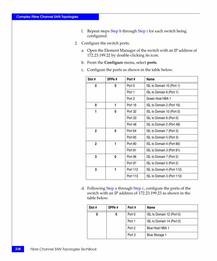
238
Complex Fibre Channel SAN Topologies
l. Repeat steps Step b through Step i for each switch being configured.
2. Configure the switch ports.
a. Open the Element Manager of the switch with an IP address of 172.23.199.22 by double-clicking its icon.
b. From the Configure menu, select ports.
c. Configure the ports as shown in the table below.
d. Following Step a through Step c, configure the ports of the switch with an IP address of 172.23.199.23 as shown in the table below.
Slot # SPPe # Port # Name
0 0 Port 0 ISL to Domain 10 (Port 1)
Port 1 ISL to Domain 6 (Port 1)
Port 2 Green Host HBA 1
0 1 Port 16 ISL to Domain 2 (Port 16)
1 0 Port 32 ISL to Domain 10 (Port 0)
Port 33 ISL to Domain 6 (Port 0)
Port 48 ISL to Domain 2 (Port 48)
2 0 Port 64 ISL to Domain 7 (Port 3)
Port 65 ISL to Domain 5 (Port 3)
2 1 Port 80 ISL to Domain 4 (Port 80)
Port 81 ISL to Domain 3 (Port 81)
3 0 Port 96 ISL to Domain 7 (Port 2)
Port 97 ISL to Domain 5 (Port 2)
3 1 Port 112 ISL to Domain 4 (Port 112)
Port 113 ISL to Domain 3 (Port 113)
Slot # SPPe # Port # Name
0 0 Port 0 ISL to Domain 12 (Port 0)
Port 1 ISL to Domain 14 (Port 0)
Port 2 Blue Host HBA 1
Port 3 Blue Storage 1
Fibre Channel SAN Topologies TechBook
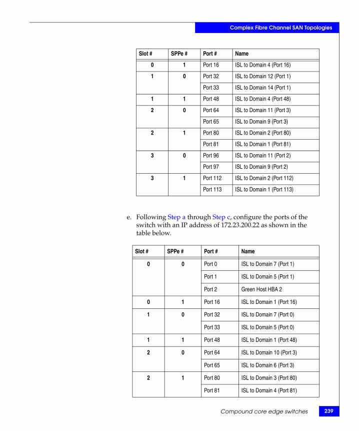
Complex Fibre Channel SAN Topologies
e. Following Step a through Step c, configure the ports of the switch with an IP address of 172.23.200.22 as shown in the table below.
0 1 Port 16 ISL to Domain 4 (Port 16)
1 0 Port 32 ISL to Domain 12 (Port 1)
Port 33 ISL to Domain 14 (Port 1)
1 1 Port 48 ISL to Domain 4 (Port 48)
2 0 Port 64 ISL to Domain 11 (Port 3)
Port 65 ISL to Domain 9 (Port 3)
2 1 Port 80 ISL to Domain 2 (Port 80)
Port 81 ISL to Domain 1 (Port 81)
3 0 Port 96 ISL to Domain 11 (Port 2)
Port 97 ISL to Domain 9 (Port 2)
3 1 Port 112 ISL to Domain 2 (Port 112)
Port 113 ISL to Domain 1 (Port 113)
Slot # SPPe # Port # Name
0 0 Port 0 ISL to Domain 7 (Port 1)
Port 1 ISL to Domain 5 (Port 1)
Port 2 Green Host HBA 2
0 1 Port 16 ISL to Domain 1 (Port 16)
1 0 Port 32 ISL to Domain 7 (Port 0)
Port 33 ISL to Domain 5 (Port 0)
1 1 Port 48 ISL to Domain 1 (Port 48)
2 0 Port 64 ISL to Domain 10 (Port 3)
Port 65 ISL to Domain 6 (Port 3)
2 1 Port 80 ISL to Domain 3 (Port 80)
Port 81 ISL to Domain 4 (Port 81)
Slot # SPPe # Port # Name
Compound core edge switches 239
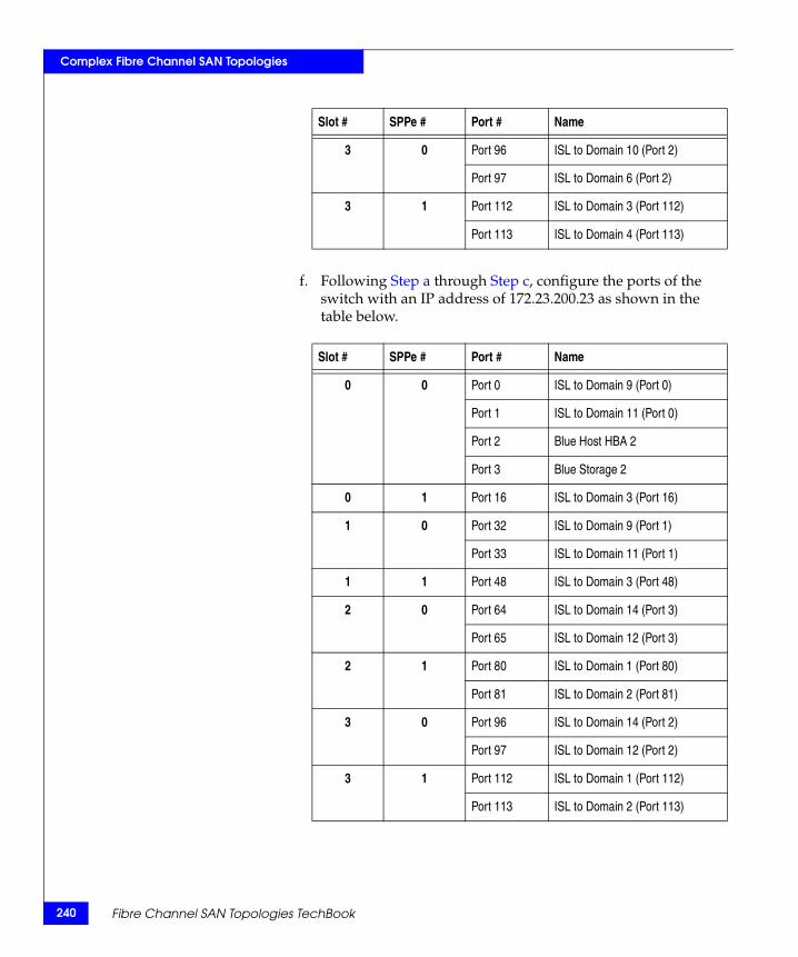
240
Complex Fibre Channel SAN Topologies
f. Following Step a through Step c, configure the ports of the switch with an IP address of 172.23.200.23 as shown in the table below.
3 0 Port 96 ISL to Domain 10 (Port 2)
Port 97 ISL to Domain 6 (Port 2)
3 1 Port 112 ISL to Domain 3 (Port 112)
Port 113 ISL to Domain 4 (Port 113)
Slot # SPPe # Port # Name
0 0 Port 0 ISL to Domain 9 (Port 0)
Port 1 ISL to Domain 11 (Port 0)
Port 2 Blue Host HBA 2
Port 3 Blue Storage 2
0 1 Port 16 ISL to Domain 3 (Port 16)
1 0 Port 32 ISL to Domain 9 (Port 1)
Port 33 ISL to Domain 11 (Port 1)
1 1 Port 48 ISL to Domain 3 (Port 48)
2 0 Port 64 ISL to Domain 14 (Port 3)
Port 65 ISL to Domain 12 (Port 3)
2 1 Port 80 ISL to Domain 1 (Port 80)
Port 81 ISL to Domain 2 (Port 81)
3 0 Port 96 ISL to Domain 14 (Port 2)
Port 97 ISL to Domain 12 (Port 2)
3 1 Port 112 ISL to Domain 1 (Port 112)
Port 113 ISL to Domain 2 (Port 113)
Slot # SPPe # Port # Name
Fibre Channel SAN Topologies TechBook
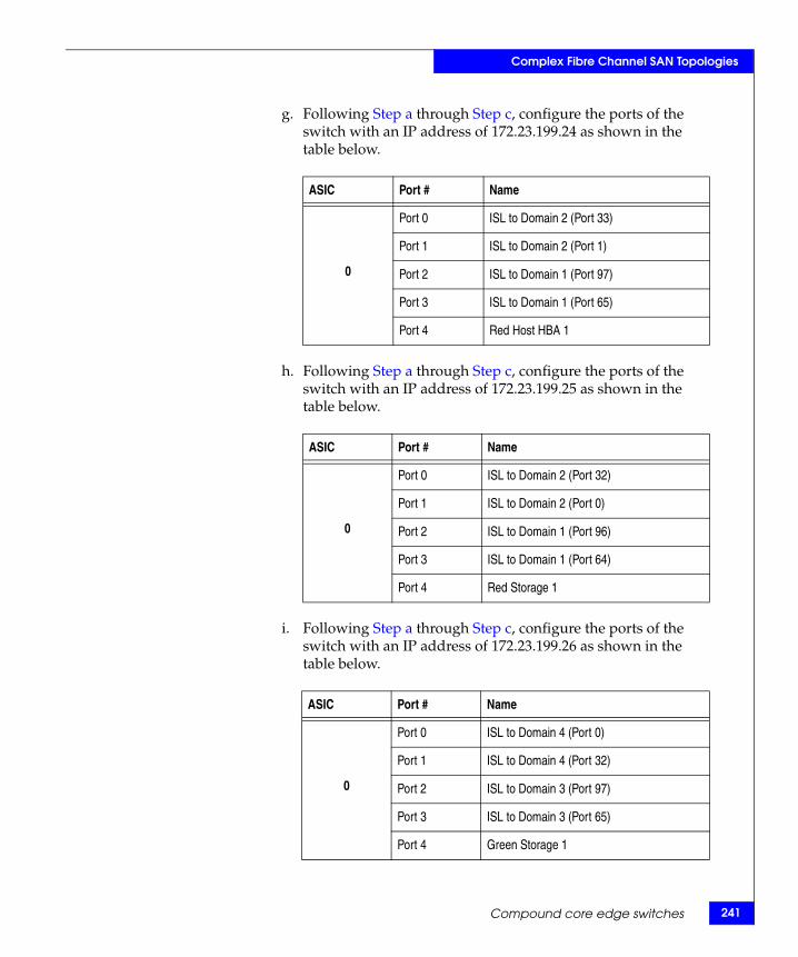
Complex Fibre Channel SAN Topologies
g. Following Step a through Step c, configure the ports of the switch with an IP address of 172.23.199.24 as shown in the table below.
h. Following Step a through Step c, configure the ports of the switch with an IP address of 172.23.199.25 as shown in the table below.
i. Following Step a through Step c, configure the ports of the switch with an IP address of 172.23.199.26 as shown in the table below.
ASIC Port # Name
0
Port 0 ISL to Domain 2 (Port 33)
Port 1 ISL to Domain 2 (Port 1)
Port 2 ISL to Domain 1 (Port 97)
Port 3 ISL to Domain 1 (Port 65)
Port 4 Red Host HBA 1
ASIC Port # Name
0
Port 0 ISL to Domain 2 (Port 32)
Port 1 ISL to Domain 2 (Port 0)
Port 2 ISL to Domain 1 (Port 96)
Port 3 ISL to Domain 1 (Port 64)
Port 4 Red Storage 1
ASIC Port # Name
0
Port 0 ISL to Domain 4 (Port 0)
Port 1 ISL to Domain 4 (Port 32)
Port 2 ISL to Domain 3 (Port 97)
Port 3 ISL to Domain 3 (Port 65)
Port 4 Green Storage 1
Compound core edge switches 241
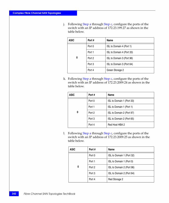
242
Complex Fibre Channel SAN Topologies
j. Following Step a through Step c, configure the ports of the switch with an IP address of 172.23.199.27 as shown in the table below.
k. Following Step a through Step c, configure the ports of the switch with an IP address of 172.23.2009.24 as shown in the table below.
l. Following Step a through Step c, configure the ports of the switch with an IP address of 172.23.2009.25 as shown in the table below.
ASIC Port # Name
0
Port 0 ISL to Domain 4 (Port 1)
Port 1 ISL to Domain 4 (Port 33)
Port 2 ISL to Domain 3 (Port 96)
Port 3 ISL to Domain 3 (Port 64)
Port 4 Green Storage 2
ASIC Port # Name
0
Port 0 ISL to Domain 1 (Port 33)
Port 1 ISL to Domain 1 (Port 1)
Port 2 ISL to Domain 2 (Port 97)
Port 3 ISL to Domain 2 (Port 65)
Port 4 Red Host HBA 2
ASIC Port # Name
0
Port 0 ISL to Domain 1 (Port 32)
Port 1 ISL to Domain 1 (Port 0)
Port 2 ISL to Domain 2 (Port 96)
Port 3 ISL to Domain 2 (Port 64)
Port 4 Red Storage 2
Fibre Channel SAN Topologies TechBook
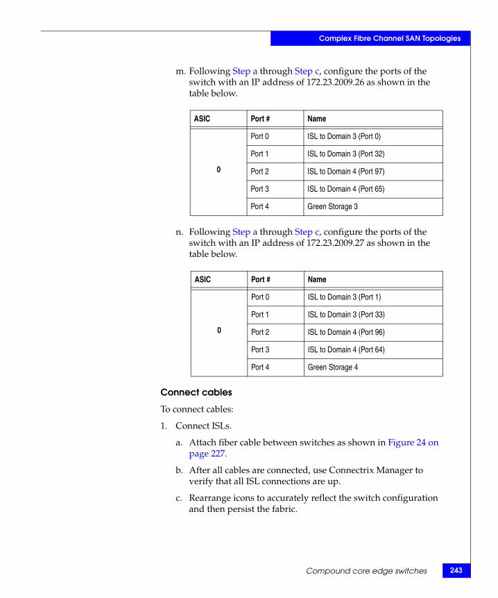
Complex Fibre Channel SAN Topologies
m. Following Step a through Step c, configure the ports of the switch with an IP address of 172.23.2009.26 as shown in the table below.
n. Following Step a through Step c, configure the ports of the switch with an IP address of 172.23.2009.27 as shown in the table below.
Connect cables
To connect cables:
1. Connect ISLs.
a. Attach fiber cable between switches as shown in Figure 24 on page 227.
b. After all cables are connected, use Connectrix Manager to verify that all ISL connections are up.
c. Rearrange icons to accurately reflect the switch configuration and then persist the fabric.
ASIC Port # Name
0
Port 0 ISL to Domain 3 (Port 0)
Port 1 ISL to Domain 3 (Port 32)
Port 2 ISL to Domain 4 (Port 97)
Port 3 ISL to Domain 4 (Port 65)
Port 4 Green Storage 3
ASIC Port # Name
0
Port 0 ISL to Domain 3 (Port 1)
Port 1 ISL to Domain 3 (Port 33)
Port 2 ISL to Domain 4 (Port 96)
Port 3 ISL to Domain 4 (Port 64)
Port 4 Green Storage 4
Compound core edge switches 243

244
Complex Fibre Channel SAN Topologies
Note: When looking at the topology view after persisting the fabric, you can immediately detect if something has changed in the environment. For example, if an ISL or device disappeared, yellow alert icons display. Because of this feature, it is recommended to always persist the fabric after changes have been made.
2. Connect the host and storage ports.
a. Attach fiber cable between switches and N_Ports.
Zone hosts and storage
To zone hosts and storage:
1. To open the Zoning dialog box in Connectrix Manager, right-click the appropriate fabric topology and then select the zoning menu.
2. Create a zone by clicking the New Zone button under the Zones Tree.
3. Provide a descriptive name for the zone. This case zones Red host HBA and Red Storage 1, so enter RedHBA1_1470_8aa, and then press Enter.
4. Locate, then click, Red Host HBA 1 (WWPN 10000000c938e554) in the potential zone members list.
5. Click the right-pointing arrow on the divider between the potential members list and the zones list to add the HBA to the zone.
6. Select Red Storage 1 (WWPN 50060482cc19bf87) in the potential zone members list.
7. Click the right-pointing arrow on the divider between the potential members list and the zones list to add the Storage port to the zone.
8. Repeat steps Step 2 through Step 7 for all host and storage pairs in the environment.
9. Create a zone set by clicking New Set under the zone sets Tree.
10. Provide a descriptive name for the zone set. This case uses the date of “Oct_31_06_1140”.
Fibre Channel SAN Topologies TechBook
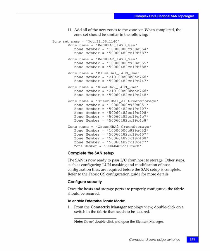
Complex Fibre Channel SAN Topologies
11. Add all of the new zones to the zone set. When completed, the zone set should be similar to the following:
Zone set name = "Oct_31_06_1140"Zone name = "RedHBA1_1470_8aa"
Zone Member = "10000000c938e554"Zone Member = "50060482cc19bf87"
Zone name = "RedHBA2_1470_9aa"Zone Member = "10000000c938e555"Zone Member = "50060482cc19bf88"
Zone name = "BlueHBA1_1489_8aa"Zone Member = "210100e08b8ac76d"Zone Member = "50060482cc19c447"
Zone name = "BlueHBA2_1489_9aa"Zone Member = "210100e08baac76d"Zone Member = "50060482cc19c448"
Zone name = "GreenHBA1_AllGreenStorage"Zone Member = "10000000c939a051"Zone Member = "50060482cc19c407"Zone Member = "50060482cc19c408"Zone Member = "50060482cc19c4c7"Zone Member = "50060482cc19c4c8"
Zone name = "GreenHBA2_GreenStorage"Zone Member = "10000000c939a052"Zone Member = "50060482cc19c407"Zone Member = "50060482cc19c408"Zone Member = "50060482cc19c4c7"Zone Member = "50060482cc19c4c8"
Complete the SAN setup
The SAN is now ready to pass I/O from host to storage. Other steps, such as configuring LUN masking and modification of host configuration files, are required before the SAN setup is complete. Refer to the Fabric OS configuration guide for more details.
Configure security
Once the hosts and storage ports are properly configured, the fabric should be secured.
To enable Enterprise Fabric Mode:
1. From the Connectrix Manager topology view, double-click on a switch in the fabric that needs to be secured.
Note: Do not double-click and open the Element Manager.
Compound core edge switches 245
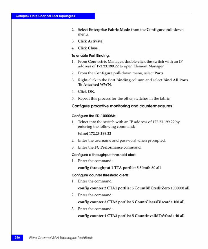
246
Complex Fibre Channel SAN Topologies
2. Select Enterprise Fabric Mode from the Configure pull-down menu.
3. Click Activate.
4. Click Close.
To enable Port Binding:
1. From Connectrix Manager, double-click the switch with an IP address of 172.23.199.22 to open Element Manager.
2. From the Configure pull-down menu, select Ports.
3. Right-click in the Port Binding column and select Bind All Ports To Attached WWN.
4. Click OK.
5. Repeat this process for the other switches in the fabric.
Configure proactive monitoring and countermeasures
Configure the ED-10000Ms:
1. Telnet into the switch with an IP address of 172.23.199.22 by entering the following command:
telnet 172.23.199.22
2. Enter the username and password when prompted.
3. Enter the FC Performance command.
Configure a throughput threshold alert:
1. Enter the command:
config throughput 1 TTA portlist 5 5 both 80 all
Configure counter threshold alerts:
1. Enter the command:
config counter 2 CTA1 portlist 5 CountBBCreditZero 1000000 all
2. Enter the command:
config counter 3 CTA2 portlist 5 CountClass3Discards 100 all
3. Enter the command:
config counter 4 CTA3 portlist 5 CountInvalidTxWords 40 all
Fibre Channel SAN Topologies TechBook
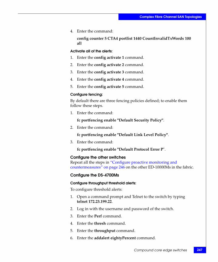
Complex Fibre Channel SAN Topologies
4. Enter the command:
config counter 5 CTA4 portlist 1440 CountInvalidTxWords 100 all
Activate all of the alerts:
1. Enter the config activate 1 command.
2. Enter the config activate 2 command.
3. Enter the config activate 3 command.
4. Enter the config activate 4 command.
5. Enter the config activate 5 command.
Configure fencing:
By default there are three fencing policies defined; to enable them follow these steps.
1. Enter the command:
fc portfencing enable "Default Security Policy".
2. Enter the command:
fc portfencing enable "Default Link Level Policy".
3. Enter the command:
fc portfencing enable "Default Protocol Error P".
Configure the other switchesRepeat all the steps in “Configure proactive monitoring and countermeasures” on page 246 on the other ED-10000Ms in the fabric.
Configure the DS-4700Ms
Configure throughput threshold alerts:
To configure threshold alerts:
1. Open a command prompt and Telnet to the switch by typing telnet 172.23.199.22.
2. Log in with the username and password of the switch.
3. Enter the Perf command.
4. Enter the thresh command.
5. Enter the throughput command.
6. Enter the addalert eightyPercent command.
Compound core edge switches 247
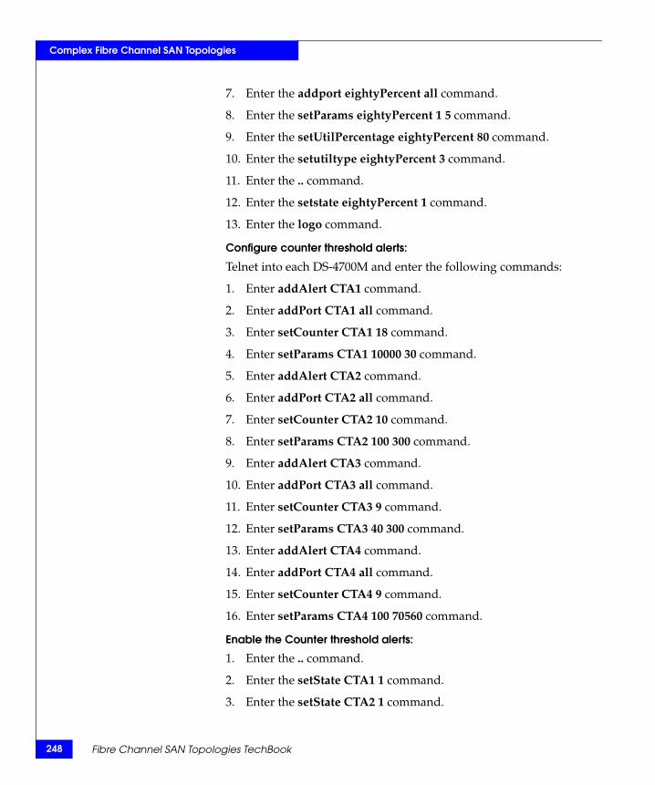
248
Complex Fibre Channel SAN Topologies
7. Enter the addport eightyPercent all command.
8. Enter the setParams eightyPercent 1 5 command.
9. Enter the setUtilPercentage eightyPercent 80 command.
10. Enter the setutiltype eightyPercent 3 command.
11. Enter the .. command.
12. Enter the setstate eightyPercent 1 command.
13. Enter the logo command.
Configure counter threshold alerts:
Telnet into each DS-4700M and enter the following commands:
1. Enter addAlert CTA1 command.
2. Enter addPort CTA1 all command.
3. Enter setCounter CTA1 18 command.
4. Enter setParams CTA1 10000 30 command.
5. Enter addAlert CTA2 command.
6. Enter addPort CTA2 all command.
7. Enter setCounter CTA2 10 command.
8. Enter setParams CTA2 100 300 command.
9. Enter addAlert CTA3 command.
10. Enter addPort CTA3 all command.
11. Enter setCounter CTA3 9 command.
12. Enter setParams CTA3 40 300 command.
13. Enter addAlert CTA4 command.
14. Enter addPort CTA4 all command.
15. Enter setCounter CTA4 9 command.
16. Enter setParams CTA4 100 70560 command.
Enable the Counter threshold alerts:
1. Enter the .. command.
2. Enter the setState CTA1 1 command.
3. Enter the setState CTA2 1 command.
Fibre Channel SAN Topologies TechBook

Complex Fibre Channel SAN Topologies
4. Enter the setState CTA3 1 command.
5. Enter the setState CTA4 1 command.
Configure Port Fencing:
1. Click Configure and select Port Fencing from the list.
2. Enable the Default Security Policy by highlighting the entry and clicking Enable.
3. Enable the Default Link Level Policy by highlighting the entry and clicking Enable.
To disable unused interfaces:
1. From the Connectrix Manager topology view, select Security.
2. Ensure that the appropriate fabric is selected in the fabric list.
3. Under the Authentication tab, select a switch in the Product Configuration list.
4. Under the Users tab clear the Enable Telnet checkbox.
Compound core edge switches 249
250
Complex Fibre Channel SAN Topologies
Heterogeneous switch interoperabilityAs SANs become larger and topologically more complex, it is increasingly advantageous to use switches from different vendors that work together. Interoperability is the term used to describe a Fibre Channel fabric that contains switches from more than one vendor. Interoperability has countless definitions in the IT connectivity space. For the context of this chapter, it refers to FC switch interoperability, which increases the ability and flexibility to design complex SANs. It takes into account the various features that different vendor switches provide as well as the specific features that end users look for while designing SANs.
This section provides an in-depth description for setting up an EMC-supported Fibre Channel SAN comprising of FC switches (director class, distribution class, departmental switches and blade server FC switch modules) from different switch vendors, such as Brocade, Cisco, Brocade M series, and QLogic. Switch migration procedures to move customers’ existing SAN topology from one EMC-supported switch vendor type to another EMC-supported vendor type are also provided.
Refer to Table 6 on page 358 for a list of all the supported switch operating modes that must be set for interop connectivity between multi-vendor switches.
The information provided in this section has been obtained from vendor product documents and testing experiences in the EMC E-Lab qualification labs.
Interoperability overview
This section explains the concept and significance of heterogeneous interoperability in the FC SAN world.
E_Portinteroperability
The approval of the FC-SW-2 standard has created an open standard for switch-to-switch communication, allowing end-users to select best-in-class products with assurance that these products will work together. Currently, most SAN switch vendors offer FC-SW-2 compliant switches including, but not limited to, Brocade, Cisco, Brocade M series, and QLogic.
Fibre Channel SAN Topologies TechBook
Complex Fibre Channel SAN Topologies
Multi-vendor FC switch interoperability is also referred to as E_Port interoperability, since two switches are connected to each other using their respective E_Ports per FC standards.
Heterogeneousinteroperability in
EMC context
EMC supports the following vendor switches in a SAN deploying switch interoperability: Brocade, Cisco, Brocade M series, and QLogic. Most of the E_Port switch connectivity-based testing between these multi-vendor switches, for different kinds of switch hardware and firmware, is conducted in the EMC E-Lab qualification labs.
The testing mainly involves the validation of:
◆ Link initialization between switches from different vendors
◆ Name server distribution
◆ Zoning changes
◆ Routing protocols
◆ Fabric management application.
Interoperability support for switches that are compatible with the FC-SW standard is listed in the "Switched Fabric Topology Parameters" section of the EMC Support Matrix.
This section comprises of the following attributes (or columns):
◆ Name of the switch
◆ Name of the switches it is interoperable with
◆ Firmware versions tested on the switch and the interoperable switches
◆ Switch (fabric) management application revision
◆ Maximum number of domains per fabric
◆ Maximum number of hops
◆ Maximum domain-to-domain ISLs supported by EMC
This information is based on the qualifications conducted at E-Lab.
Although the support matrix can only directly represent a two-way interop, it may also be used to represent a three-way interop. Consider there are three switches, each from a different vendor, running firmware versions A, B, and C, respectively.
If the following entries are present in the support matrix:
◆ A is interoperable with B
Heterogeneous switch interoperability 251

252
Complex Fibre Channel SAN Topologies
◆ A is interoperable with C
◆ B is interoperable with C
then one can infer that switches running firmware versions A, B, and C are interoperable and can co-exist in the same fabric.
Significance of amulti-vendor switch
configuration
There are at least three user scenarios that indicate the significance of a multi-vendor switch environment:
User scenario 1: Complex SANs
As SANs become larger and topologically more complex, it is getting increasingly useful to get switches from different vendors to work together. As discussed above, there are various vendors in the FC industry, designing and manufacturing switch hardware with different hardware features, protocol related-features, and performance (2 G/4 G/10 G). In such a case, end users must be able to select the best in-class products to design a SAN that meets their needs in terms of features and performance.
User scenario 2: Blade servers
Blade server technology is becoming widely accepted, but it is still evolving. At the time of this publication, only some switch vendors, such as Brocade, Brocade M series, and QLogic, are manufacturing FC switch modules that can be plugged into the backend of a blade server. A blade server accesses a switched fabric or storage it is being hooked up to using FC switch modules (as discussed in detail in "Blade servers" in the Non-EMC SAN Products Data Reference Manual, available through the E-Lab Interoperability Navigator, Topology Resource Center tab, at http://elabnavigator.EMC.com). Hence, if end users have a switch-vendor fabric which is neither of the above switch module manufacturing vendors, interoperability between multi-vendor switches is an important aspect to consider before building such a fabric.
User scenario 3: Switch migration
Depending on their requirements, some end users move their SAN from one switch vendor type to another switch vendor type. This switch migration procedure needs to be executed in phases. One of the transitional phases requires the vendor type switches (one type before and the other after the migration) to be in the same fabric, making interoperability between multi-vendor switches an aspect to be considered before starting a switch migration procedure.
Fibre Channel SAN Topologies TechBook
Complex Fibre Channel SAN Topologies
Heterogeneous SAN designThis section provides details on setting up an interoperable SAN environment, and studies different combinations of some of the EMC-supported heterogeneous SANs.
In addition to providing a detailed step-by-step approach to design some specific type of SANs, this section is intended to give you an insight into the kind of configurations previously tested and supported by E-Lab, and to provide some of the best practices and caveats that must be considered while designing these SANs.
Components neededto create a
heterogeneousdesign
The concept of simple SANs and Complex SANs has been discussed in detail in “Best practices” on page 138. Most of the discussed topologies comprising of at least two switches are applicable to designing heterogeneous SANs. It is important to note that:
◆ In the heterogeneous SANs, the switched fabric must be comprised of switches from two or more different vendors.
◆ It is essential to set the appropriate operational mode on the switches so that they can communicate with any other switch from a different vendor in the same fabric.
How to set up an interoperable switched fabric topologyIn order to address the individual vendor switch settings for supported switch interoperability configurations, a cookbook approach is used to explain a seven phase switch vendor migration process. The assumptions for this seven phase migration process follows.
Assumptions for the 7 phase migration process
◆ In all cases, the case studies start with a homogeneous single vendor fabric.
◆ Compound core edge topology is used for these case studies.
◆ The switch migration process involves a step to move the edge switches from the same vendor type core switches to a different vendor type core switches.
Note: This process is helpful to end users who want to move their fabrics from one vendor switch core type to another vendor switch core type.
Heterogeneous switch interoperability 253

254
Complex Fibre Channel SAN Topologies
◆ One of the steps in the migration involves a stage when different vendor switches co-exist in the same fabric.
Note: This can help end users set up a supported interoperability fabric based on the switch configuration settings from different vendors that can co-exist in a stable fabric.
Phases The seven phase process that has been appointed across all the case studies is explained in detail in the following sections. This example shows a transition from a switched fabric topology using Vendor A switches, to a topology with Vendor B switches.
Phase 1: This is the base configuration phase with the pre-existing Vendor A switched fabric topology. Some default settings on these switches need to be changed before introducing a Vendor B switch in this fabric.
Phase 2: In this phase, a Vendor B core switch is added to the homogeneous Vendor A fabric. This implies that all the Vendor A edge switches now have ISLs to this core Vendor B switch.
Phase 3: Half of the zoned initiator (hosts) and target (storage) pairs from a Vendor A core switch are moved to the Vendor B core switch.
Phase 4:All the other initiator-target pairs from the Vendor A core switches are completely moved to the Vendor B core switch.
Note: Phase 3 and 4 are executed in steps to avoid any disruption of traffic between the host and storage during the transition and to avoid any downtime.
Phase 5: One or more Vendor B switches are added to the edge of the fabric.
Phase 6:Hosts and storage are moved from any Vendor A edge switches to the new Vendor B edge switches.
Phase 7:More Vendor B switches are added, if required, to the core of the fabric.
Fibre Channel SAN Topologies TechBook
Complex Fibre Channel SAN Topologies
Case studies Based on the switch vendor types and the interoperability modes currently tested and supported by EMC, five case studies are described in this section.
Case study #1: Migrating from a Connectrix M homogeneous fabric in McDATA fabric mode to a Connectrix MDS fabric.
Assumptions specific to this case study:
◆ Interoperability mode settings on the switches:
• Brocade M series Fabric 1.0 mode on the Connectrix M switches in the fabric.
• Cisco Interop-4 mode on the Connectrix MDS switches in the fabric.
Note: At the time of this release, EMC supports Interop-4 using RPQ for migration purposes only. Please refer to the EMC Support Matrix for the most up-to-date support.
◆ Fabric management applications used for managing the fabric:
• Cisco Fabric Manager, Connectrix Manager, Connectrix Manager, Connectrix Manager Basic, or Connectrix Manager Basic
• Phase 1: Base configuration — Pre-existing Connectrix M series Core-Edge Fabric
Heterogeneous switch interoperability 255
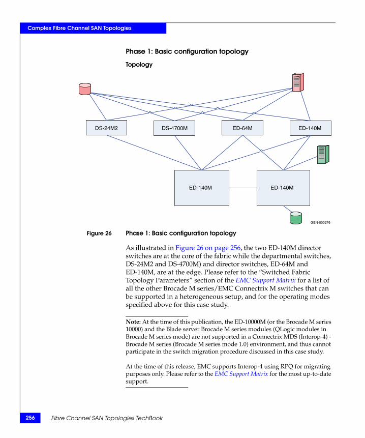
256
Complex Fibre Channel SAN Topologies
Phase 1: Basic configuration topology
Topology
Figure 26 Phase 1: Basic configuration topology
As illustrated in Figure 26 on page 256, the two ED-140M director switches are at the core of the fabric while the departmental switches, DS-24M2 and DS-4700M) and director switches, ED-64M and ED-140M, are at the edge. Please refer to the “Switched Fabric Topology Parameters” section of the EMC Support Matrix for a list of all the other Brocade M series/EMC Connectrix M switches that can be supported in a heterogeneous setup, and for the operating modes specified above for this case study.
Note: At the time of this publication, the ED-10000M (or the Brocade M series 10000) and the Blade server Brocade M series modules (QLogic modules in Brocade M series mode) are not supported in a Connectrix MDS (Interop-4) - Brocade M series (Brocade M series mode 1.0) environment, and thus cannot participate in the switch migration procedure discussed in this case study.
At the time of this release, EMC supports Interop-4 using RPQ for migrating purposes only. Please refer to the EMC Support Matrix for the most up-to-date support.
GEN-000276
DS-24M2 DS-4700M ED-64M ED-140M
ED-140M ED-140M
Fibre Channel SAN Topologies TechBook
Complex Fibre Channel SAN Topologies
The specific configuration settings, best practices, host and storage layouts, and topology design to withstand failures for a Connectrix M core-edge homogeneous fabric discussed in the “Connectrix M example” on page 163 applies to this base topology.
Checkpoints
Before adding the Connectrix MDS core MDS 9513 director to the homogeneous Brocade M series fabric, it is advisable to verify the following fabric characteristics using either Connectrix Manager, Connectrix Manager Basic, or the Brocade M series CLI:
◆ Proper distribution of the name server information.
Verify that all the host HBA ports and storage ports logged into the fabric are listed in the name server.
◆ Proper distribution of zoning information.
Verify that the active zoneset comprises zones that contain the desired mapping of host and storage ports.
◆ Proper display of fabric and N_Port elements on the management applications.
Verify that you have the desired physical topology and domain count of the fabric.
◆ No disruption in data transfer.
Verify that the data traffic is running appropriately through the SAN.
Heterogeneous switch interoperability 257
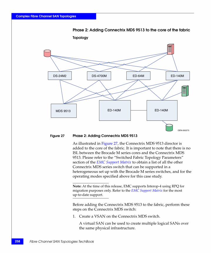
258
Complex Fibre Channel SAN Topologies
Phase 2: Adding Connectrix MDS 9513 to the core of the fabric
Topology
Figure 27 Phase 2: Adding Connectrix MDS 9513
As illustrated in Figure 27, the Connectrix MDS 9513 director is added to the core of the fabric. It is important to note that there is no ISL between the Brocade M series cores and the Connectrix MDS 9513. Please refer to the “Switched Fabric Topology Parameters” section of the EMC Support Matrix to obtain a list of all the other Connectrix MDS series switch that can be supported in a heterogeneous set up with the Brocade M series switches, and for the operating modes specified above for this case study.
Note: At the time of this release, EMC supports Interop-4 using RPQ for migration purposes only. Refer to the EMC Support Matrix for the most up-to-date support.
Before adding the Connectrix MDS 9513 to the fabric, perform these steps on the Connectrix MDS switch:
1. Create a VSAN on the Connectrix MDS switch.
A virtual SAN can be used to create multiple logical SANs over the same physical infrastructure.
GEN-000275
DS-24M2 DS-4700M ED-64M ED-140M
ED-140M ED-140MMDS 9513
Fibre Channel SAN Topologies TechBook
Complex Fibre Channel SAN Topologies
a. Click Create VSAN on the Cisco Fabric Manager.
b. When the Create VSAN window appears, check the desired switches to included in the VSAN. In this case, only the MDS 9513.
c. Fill in the VSAN ID field with an unused ID number and the VSAN name filed with an appropriate name. In this case study, VSAN ID number = 801.
d. For VSN attributes, leave everything other than the InterOperValue and the AdminState at default.
e. Set InterOperValue to Interop-4 and the AdminState to Suspended.
f. Statically assign VSAN membership for an interface using Fabric Manager, by selecting Interfaces > FC Physical from the Physical Attributes pane.
The interface configuration in the Information pane appears. Click the General tab and double-click to complete the PortVSAN field by entering the VSAN ID number (801) for every desired port for this fabric.
For more details on the VSAN settings for Connectrix MDS 9000 family switches refer to the Cisco document located at http://www.cisco.com.
For configuring Interop-4 specific settings on the Cisco CLI refer to the Cisco document located at http://www.cisco.com.
Interop mode 4, also known as the legacy switch Interop mode 4, provides easy integration between VSANs and Brocade M series switches running in Brocade M series Fabric 1.0 interop mode. It is initially available with Connectrix MDS 9000 SAN-OS v. 3.0(1). Thus, there is no need to reset or restart Brocade M series switches in this case study since they can continue to operate in Brocade M series fabric mode 1.0 which avoids fabric disruption.
2. To set up interoperability configuration compliant with Connectrix M switches operating in Brocade M series Fabric Mode 1.0:
a. Select VSAN 801 from the Logical Domains menu on the Fabric Manager.
Heterogeneous switch interoperability 259
260
Complex Fibre Channel SAN Topologies
b. Select VSAN attributes. VSAN attributes can be seen in the information pane.
c. Select Interop-4 from the interop drop-down menu.
d. Click Insert Row.
3. To set up interoperability configuration compliant with Connectrix M switches operating in Brocade M series Fabric Mode 1.0:
a. Replace the local switch WWN with the Brocade M series OUI.
A VSAN running in Interop mode 4 must be configured to use a WWN that follows a specific set of rules regarding the following Brocade M series OUI format:
The changed WWN with the Brocade M series OUI must appear as xy:yy:08:00:88:zz:zz:zz.
– x = 1 or 2. – y = 0:00 or hex representation of the VSAN number. (For
example, 0:0a for VSAN 10.) – 3rd, 4th and 5th bytes of the WWN must be 08:00:88
(Brocade M series OUI). – Recommended: z = last three bytes of the switch WWN. – The chosen WWN must be unique across the fabric. Once completed, the WWN has a Brocade M series OUI and the WWN can conflict only with Brocade M series switches or other Connectrix MDS switches with VSANs running in Interop mode 4.
b. Set a static Domain ID:
If you configure a static Domain ID using Domain Manager on the Logical Domains menu of the Connectrix MDS switch Fabric Manager, it must be in the 1 to 31 range for the Interop mode 4 VSAN. However, persistent FC IDs must be configured in the range of 97 to 127. A Connectrix M switch refers to Domain IDs in the range of 1 to 31, while FC IDs are used within the range of 97 to 127, with an offset of 96. The Interop mode 4 VSAN emulates the same behavior as the Connectrix M switch. Therefore, when configuring static Domain IDs on an Connectrix MDS switch, the range of 1 to 31 should be used; however, devices that log in to the VSAN (even physically located on the Connectrix MDS switch)
Fibre Channel SAN Topologies TechBook
Complex Fibre Channel SAN Topologies
receive an FC ID whose Domain ID is 97 – 127. The DID range for Connectrix MDS in interop-4 is thus reduced from 1 – 239 to 1 – 31.
4. To set ports on the Device Manager for the Connectrix MDS 9513:
a. Select the desired switch, in this case Connectrix MDS 9513. The Device Manager appears.
b. Select the ports participating in this fabric, and set the port speed to automax 2 G. Leave the other settings as default.
c. Set the Admin option to up.
5. Unsuspend the VSAN.
After configuring all the settings as stated in Step 4, go back to the VSAN attributes and change the AdminState to Active.
IMPORTANT!Before connecting the Connectrix MDS switch to the Connectrix M switches through an ISL, it is important to verify that all the Connectrix M switches and the Connectrix MDS switches are running the supported firmware versions for the respective interop modes. To verify the versions, refer to the EMC Support Matrix.
6. Create an ISL between the Connectrix MDS 9513 and all the Connectrix M edge switches as per Figure 27 on page 258.
7. Verify connectivity of the fabric by validating the same set of checkpoints as listed for “Checkpoints” on page 257. In this case, Cisco Fabric Manager and Cisco CLI can be used to verify the fabric topology and name server information.
IMPORTANT!At the end of this phase, it is highly recommended you verify that zoning information was distributed appropriately to the Connectrix MDS core. You must compare the active zone set on the Connectrix M and Connectrix MDS fabric management tools to verify that there are no differences.
On Connectrix Manager, a Connectrix MDS switch appear as a Connectrix M switch. However, by clicking Discover > Setup on Connectrix Manager, and adding the IP of the Connectrix MDS switch, the Connectrix M switch is discovered as a Connectrix MDS
Heterogeneous switch interoperability 261
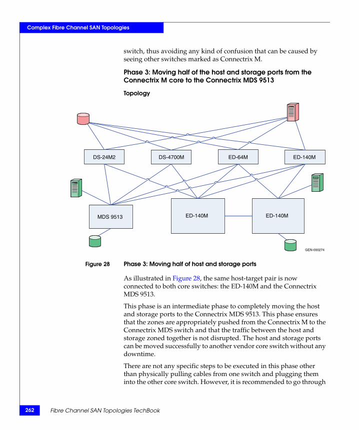
262
Complex Fibre Channel SAN Topologies
switch, thus avoiding any kind of confusion that can be caused by seeing other switches marked as Connectrix M.
Phase 3: Moving half of the host and storage ports from the Connectrix M core to the Connectrix MDS 9513
Topology
Figure 28 Phase 3: Moving half of host and storage ports
As illustrated in Figure 28, the same host-target pair is now connected to both core switches: the ED-140M and the Connectrix MDS 9513.
This phase is an intermediate phase to completely moving the host and storage ports to the Connectrix MDS 9513. This phase ensures that the zones are appropriately pushed from the Connectrix M to the Connectrix MDS switch and that the traffic between the host and storage zoned together is not disrupted. The host and storage ports can be moved successfully to another vendor core switch without any downtime.
There are not any specific steps to be executed in this phase other than physically pulling cables from one switch and plugging them into the other core switch. However, it is recommended to go through
GEN-000274
DS-24M2 DS-4700M ED-64M ED-140M
ED-140M ED-140MMDS 9513
Fibre Channel SAN Topologies TechBook
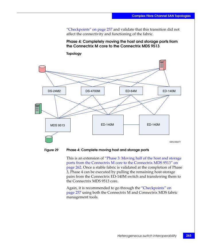
Complex Fibre Channel SAN Topologies
“Checkpoints” on page 257 and validate that this transition did not affect the connectivity and functioning of the fabric.
Phase 4: Completely moving the host and storage ports from the Connectrix M core to the Connectrix MDS 9513
Topology
Figure 29 Phase 4: Complete moving host and storage ports
This is an extension of “Phase 3: Moving half of the host and storage ports from the Connectrix M core to the Connectrix MDS 9513” on page 262. Once a stable fabric is validated at the completion of Phase 3, Phase 4 can be executed by pulling the remaining host-storage pairs from the Connectrix ED-140M switch and transferring them to the Connectrix MDS 9513 core.
Again, it is recommended to go through the “Checkpoints” on page 257 using both the Connectrix M and Connectrix MDS fabric management tools.
GEN-000277
DS-24M2 DS-4700M ED-64M ED-140M
ED-140M ED-140MMDS 9513
Heterogeneous switch interoperability 263
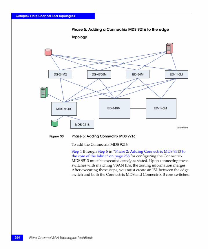
264
Complex Fibre Channel SAN Topologies
Phase 5: Adding a Connectrix MDS 9216 to the edge
Topology
Figure 30 Phase 5: Adding Connectrix MDS 9216
To add the Connectrix MDS 9216:
Step 1 through Step 5 in “Phase 2: Adding Connectrix MDS 9513 to the core of the fabric” on page 258 for configuring the Connectrix MDS 9513 must be executed exactly as stated. Upon connecting these switches with matching VSAN IDs, the zoning information merges. After executing these steps, you must create an ISL between the edge switch and both the Connectrix MDS and Connectrix B core switches.
GEN-000278
DS-24M2
MDS 9216
DS-4700M ED-64M ED-140M
ED-140M ED-140MMDS 9513
Fibre Channel SAN Topologies TechBook
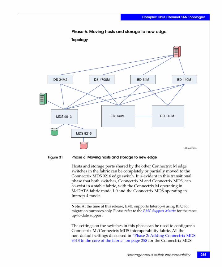
Complex Fibre Channel SAN Topologies
Phase 6: Moving hosts and storage to new edge
Topology
Figure 31 Phase 6: Moving hosts and storage to new edge
Hosts and storage ports shared by the other Connectrix M edge switches in the fabric can be completely or partially moved to the Connectrix MDS 9216 edge switch. It is evident in this transitional phase that both switches, Connectrix M and Connectrix MDS, can co-exist in a stable fabric, with the Connectrix M operating in McDATA fabric mode 1.0 and the Connectrix MDS operating in Interop-4 mode.
Note: At the time of this release, EMC supports Interop-4 using RPQ for migration purposes only. Please refer to the EMC Support Matrix for the most up-to-date support.
The settings on the switches in this phase can be used to configure a Connectrix M/Connectrix MDS interoperability fabric. All the non-default settings discussed in “Phase 2: Adding Connectrix MDS 9513 to the core of the fabric” on page 258 for the Connectrix MDS
GEN-000279
DS-24M2
MDS 9216
DS-4700M ED-64M ED-140M
ED-140M ED-140MMDS 9513
Heterogeneous switch interoperability 265
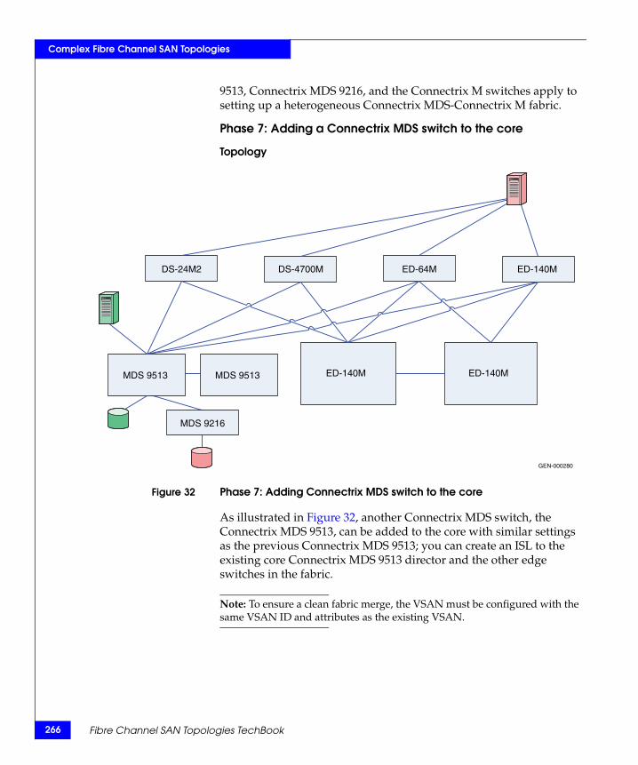
266
Complex Fibre Channel SAN Topologies
9513, Connectrix MDS 9216, and the Connectrix M switches apply to setting up a heterogeneous Connectrix MDS-Connectrix M fabric.
Phase 7: Adding a Connectrix MDS switch to the core
Topology
Figure 32 Phase 7: Adding Connectrix MDS switch to the core
As illustrated in Figure 32, another Connectrix MDS switch, the Connectrix MDS 9513, can be added to the core with similar settings as the previous Connectrix MDS 9513; you can create an ISL to the existing core Connectrix MDS 9513 director and the other edge switches in the fabric.
Note: To ensure a clean fabric merge, the VSAN must be configured with the same VSAN ID and attributes as the existing VSAN.
GEN-000280
DS-24M2
MDS 9216
DS-4700M ED-64M ED-140M
ED-140M ED-140MMDS 9513 MDS 9513
Fibre Channel SAN Topologies TechBook
Complex Fibre Channel SAN Topologies
Complete migration to Connectrix MDS
At the end of case study 1, a migration from a Connectrix M-only fabric to a Connectrix M-Connectrix MDS fabric with Connectrix MDS switches at the core, connected through ISLs to every edge switch in the fabric, occurred. The host and storage ports (except for the blade server host ports) can be completely moved over to the Connectrix MDS switches as specified in Phases 3, 4, and 6. The Connectrix M edge switches (except for the blade server Brocade M series switch modules) and the Connectrix M core switches can then be pulled out from the fabric. A fully operational Connectrix MDS-only fabric exists when completed. This is a complete migration from one switch type (Connectrix M) to another type (Connectrix MDS).
IMPORTANT!In a Connectrix MDS-only fabric, it is recommended that all Connectrix MDS switches operate in (default) mode.At the end of the migration explained in this case study, Connectrix MDS switches are in interop mode.
In order to change interop mode on the Connectrix MDS switches, do not reboot the switches. The Interop mode attribute on currently active VSANs must be changed from Interop-4 to Default.
Note: At the time of this release, EMC supports Interop-4 using RPQ for migration purposes only. Please refer to the EMC Support Matrix for the most up-to-date support.
However, active zones that were pushed to the Connectrix MDS from the Connectrix M cannot be modified once interop mode on the Connectrix MDS is changed. Zoning must be reconfigured. It is highly recommended that you back up the configuration to avoid losing all zoning information in the active zoneset on Connectrix MDS switches.
Warnings or caveats
Refer to EMC Knowledgebase solution emc149735 for all interop issues.
Heterogeneous switch interoperability 267
268
Complex Fibre Channel SAN Topologies
Case study #2 Setting up a heterogeneous switched fabric with Connectrix M switches in Open Fabric mode and the Connectrix MDS switches in Interop-1 mode.
Assumptions specific to this case study:
◆ Interoperability mode settings on the switches:
• Brocade M series Open Fabric 1.0 mode on Brocade M series switches in the fabric.
• Cisco Interop-1 mode on Cisco switches in the fabric.
◆ Fabric management applications used for managing the fabric:
• Cisco Fabric Manager, Connectrix Manager, or Connectrix Manager Basic
If you migrate a Connectrix M fabric to a Connectrix MDS fabric (when the ED-10000M is not a part of the fabric), keep the fabric in Brocade M series Mode and follow the migration process as explained in “Case study #1:” on page 255. In this case study, when migrating from a Connectrix M fabric to a Cisco fabric, the non-default settings must be configured on Connectrix M and the Connectrix MDS switches before they are linked with an ISL.
Fibre Channel SAN Topologies TechBook
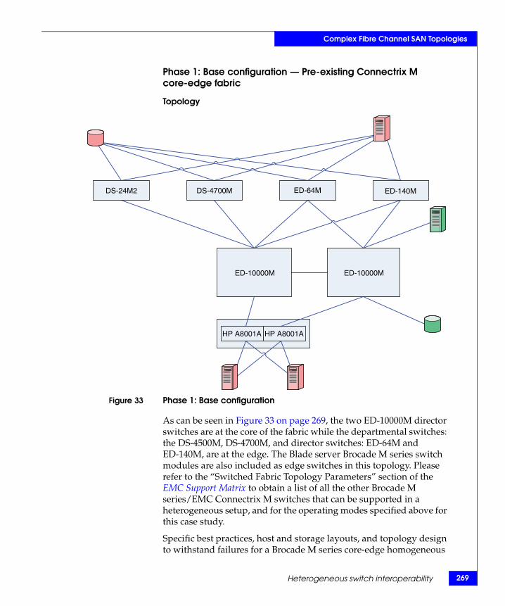
Complex Fibre Channel SAN Topologies
Phase 1: Base configuration — Pre-existing Connectrix M core-edge fabric
Topology
Figure 33 Phase 1: Base configuration
As can be seen in Figure 33 on page 269, the two ED-10000M director switches are at the core of the fabric while the departmental switches: the DS-4500M, DS-4700M, and director switches: ED-64M and ED-140M, are at the edge. The Blade server Brocade M series switch modules are also included as edge switches in this topology. Please refer to the “Switched Fabric Topology Parameters” section of the EMC Support Matrix to obtain a list of all the other Brocade M series/EMC Connectrix M switches that can be supported in a heterogeneous setup, and for the operating modes specified above for this case study.
Specific best practices, host and storage layouts, and topology design to withstand failures for a Brocade M series core-edge homogeneous
DS-24M2 DS-4700M ED-64M ED-140M
ED-10000M ED-10000M
HP A8001A HP A8001A
Heterogeneous switch interoperability 269
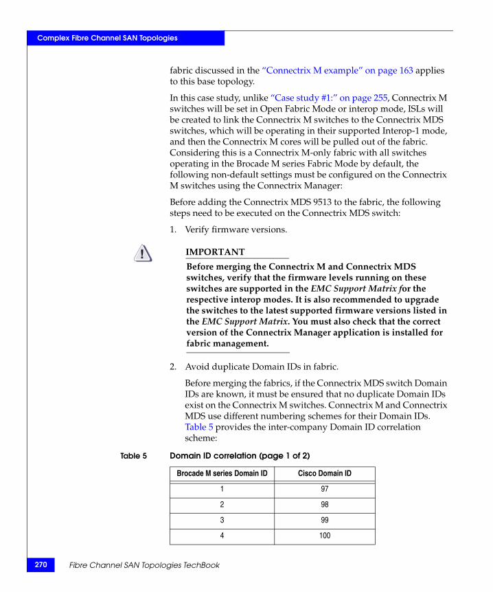
270
Complex Fibre Channel SAN Topologies
fabric discussed in the “Connectrix M example” on page 163 applies to this base topology.
In this case study, unlike “Case study #1:” on page 255, Connectrix M switches will be set in Open Fabric Mode or interop mode, ISLs will be created to link the Connectrix M switches to the Connectrix MDS switches, which will be operating in their supported Interop-1 mode, and then the Connectrix M cores will be pulled out of the fabric. Considering this is a Connectrix M-only fabric with all switches operating in the Brocade M series Fabric Mode by default, the following non-default settings must be configured on the Connectrix M switches using the Connectrix Manager:
Before adding the Connectrix MDS 9513 to the fabric, the following steps need to be executed on the Connectrix MDS switch:
1. Verify firmware versions.
IMPORTANT!Before merging the Connectrix M and Connectrix MDS switches, verify that the firmware levels running on these switches are supported in the EMC Support Matrix for the respective interop modes. It is also recommended to upgrade the switches to the latest supported firmware versions listed in the EMC Support Matrix. You must also check that the correct version of the Connectrix Manager application is installed for fabric management.
2. Avoid duplicate Domain IDs in fabric.
Before merging the fabrics, if the Connectrix MDS switch Domain IDs are known, it must be ensured that no duplicate Domain IDs exist on the Connectrix M switches. Connectrix M and Connectrix MDS use different numbering schemes for their Domain IDs. Table 5 provides the inter-company Domain ID correlation scheme:
Table 5 Domain ID correlation (page 1 of 2)
Brocade M series Domain ID Cisco Domain ID
1 97
2 98
3 99
4 100
Fibre Channel SAN Topologies TechBook
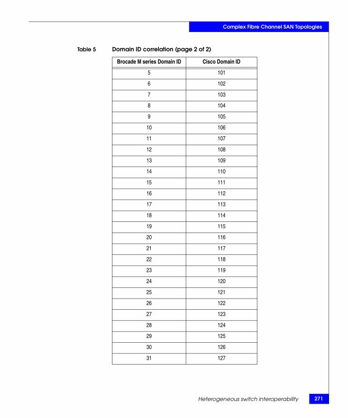
Complex Fibre Channel SAN Topologies
5 101
6 102
7 103
8 104
9 105
10 106
11 107
12 108
13 109
14 110
15 111
16 112
17 113
18 114
19 115
20 116
21 117
22 118
23 119
24 120
25 121
26 122
27 123
28 124
29 125
30 126
31 127
Table 5 Domain ID correlation (page 2 of 2)
Brocade M series Domain ID Cisco Domain ID
Heterogeneous switch interoperability 271
272
Complex Fibre Channel SAN Topologies
If there is a Connectrix M fabric that consists of Connectrix M switches with Domain IDs of 1 and 2, and another Connectrix MDS fabric that consists of Connectrix MDS switches with Domain IDs of 97(1) and 98(2), an attempted fabric merge will fail because duplicate Domain IDs will cause the fabrics to segment.
How to configure the preferred Domain ID and set it as a persistent ID using Connectrix Manager is addressed in“Configure the first virtual switch” on page 99.
3. Verify Interop Mode.
The correct interoperation mode: Open Fabric Mode 1.0 must be set on the Connectrix M switches in the fabric before merging them with Connectrix MDS. The Interop mode can be verified and changed using Connectrix Manager as follows:
a. Before changing the interop mode for a Brocade M series switch, the switch must be set “offline”.
b. At the Connectrix Manager window, right click the appropriate product icon at the physical map. A pop-up menu appears. Select Element Manager from the menu.
When the Element Manager application opens, the last view (tab) accessed by an end-user opens by default.
c. At the Configure menu in the Element Manager, select Operating Parameters, then Fabric Parameters. The Configure fabric Parameters dialog box appears.
d. At the Interop Mode drop-down list, select Open Fabric 1.0 and click Activate.
4. Disable Rerouting Delay for the Connectrix M switches.
In an interoperability scenario, the Rerouting Delay on Brocade M series switches must be disabled using the Connectrix Manager management application as follows:
a. At the Connectrix Manager window, right-click the appropriate product icon at the physical map. A pop-up menu appears. Select Element Manager from the menu.
When the Element Manager application opens, the last view (tab) accessed by an end-user opens by default.
b. At the Configure menu in the Element Manager, select Operating Parameters, then Switch Parameters. The Configure Switch Parameters dialog box displays.
Fibre Channel SAN Topologies TechBook
Complex Fibre Channel SAN Topologies
c. Ensure the Rerouting delay checkbox is not selected (checked),and then click Activate.
5. Set Connectrix M port speed and port type for Connectrix MDS.
Ensure that the port speeds and port types are configured equally between the Connectrix M switches and the Connectrix MDS switches to be merged. The port speed may be set to auto-negotiate and the ports to be linked with ISLs to each other can be locked as E_Ports. The port configuration steps using the Connectrix Manager management GUI were explained in “Configure the first virtual switch” on page 99.
For more details on the settings to be applied to the Connectrix M switches before merging them with a Connectrix MDS fabric are provided in documentation located at http://www.cisco.com.
Checkpoints
Before adding the Connectrix MDS core Connectrix MDS 9513 director to the homogeneous Connectrix M fabric, it is advisable to verify the following fabric characteristics using either the Connectrix Manager or the Brocade M series CLI.
◆ Proper distribution of the Name Server information.
Verify that all the host HBA ports and storage ports logged into the fabric are listed in the name server.
◆ Proper distribution of Zoning information.
Verify that the active zoneset comprises of the zones that contain the desired mapping of host and storage ports.
◆ Proper display of fabric and N_Port elements on the management applications.
Verify that the physical topology and domain count of the fabric is as desired.
◆ No disruption in data transfer.
Verify that the data traffic is running appropriately through the SAN.
Heterogeneous switch interoperability 273
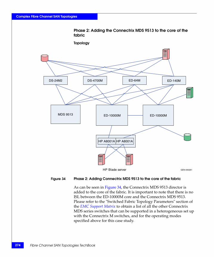
274
Complex Fibre Channel SAN Topologies
Phase 2: Adding the Connectrix MDS 9513 to the core of the fabric
Topology
Figure 34 Phase 2: Adding Connectrix MDS 9513 to the core of the fabric
As can be seen in Figure 34, the Connectrix MDS 9513 director is added to the core of the fabric. It is important to note that there is no ISL between the ED-10000M core and the Connectrix MDS 9513. Please refer to the "Switched Fabric Topology Parameters" section of the EMC Support Matrix to obtain a list of all the other Connectrix MDS series switches that can be supported in a heterogeneous set up with the Connectrix M switches, and for the operating modes specified above for this case study.
HP Blade server
DS-24M2 DS-4700M ED-64M ED-140M
MDS 9513 ED-10000M ED-10000M
HP A8001A HP A8001A
GEN-000261
Fibre Channel SAN Topologies TechBook
Complex Fibre Channel SAN Topologies
Before adding the Connectrix MDS 9513 to the fabric, the following steps need to be executed on the Connectrix MDS switch:
1. Create a VSAN on the Connectrix MDS switch.
A Virtual SAN can be used to create multiple logical SANs over the same physical infrastructure.
a. Click Create VSAN on Cisco Fabric Manager.
b. Once the Create VSAN window appears, select the switches to include in the VSAN. In this case, only the Connectrix MDS 9513 is included.
c. Fill in the VSAN ID field with an unused ID number and the VSAN name filed with an appropriate name. In this case study, VSAN ID number = 801 is assigned.
d. For VSAN attributes, leave everything other than the InterOperValue and the AdminState at default. VSAN attributes can be seen in the information pane.
e. Set InterOperValue to Interop-1 and the AdminState to Suspended.
f. Statically assign VSAN membership for an interface using Fabric Manager, by choosing Interfaces > FC Physical from the Physical Attributes pane. The interface configuration appears in the Information pane. Select the General tab on this window, and double-click and complete the PortVSAN field by entering the VSAN ID number (801) for every port desired to be used by this fabric.
For more details on the VSAN settings and for configuring the Interop-1 specific settings for Connectrix MDS 9000 family switches refer to Cisco document located at http://www.cisco.com.
2. To set port settings on the Device Manager for the Connectrix MDS 9513:
a. Select the desired switch in this case, the Connectrix MDS 9513. The Device Manager appears.
b. Select the ports participating in this fabric and set the port speed to automax 2 G. Leave the other settings as default.
c. Set the Admin option to up.
3. Unsuspend the VSAN.
Heterogeneous switch interoperability 275
276
Complex Fibre Channel SAN Topologies
After configuring all the settings as stated above, go back to the VSAN attributes and change the AdminState to Active.
4. Link, using an ISL, the Connectrix MDS 9513 to all the Connectrix M edge switches as shown in Figure 34 on page 274.
5. Verify connectivity of the fabric by validating the same set of checkpoints as listed for “Checkpoints” on page 273 of this case study. In this case, even the Cisco Fabric Manager and Cisco CLI can be used to verify the fabric topology and name server information.
IMPORTANT!At the end of this phase, it is highly recommended to check that the zoning information has been distributed appropriately to the Connectrix MDS core. The active zoneset on the Connectrix M and Connectrix MDS fabric management tools must be compared to verify that there are no differences.
On Connectrix Manager, the Connectrix MDS appears as a Connectrix M switch. If you select Discover > Setup on Connectrix Manager and add the IP of the Connectrix MDS switch, the Connectrix M switch is discovered as a Connectrix MDS switch, thus avoiding confusion.
Fibre Channel SAN Topologies TechBook
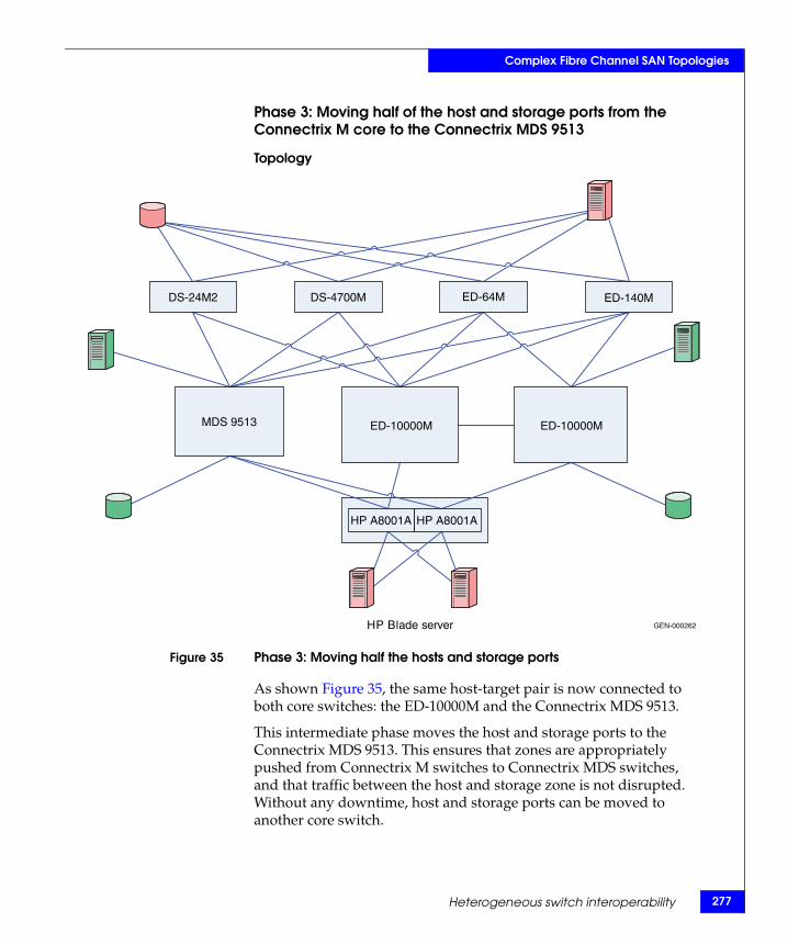
Complex Fibre Channel SAN Topologies
Phase 3: Moving half of the host and storage ports from the Connectrix M core to the Connectrix MDS 9513
Topology
Figure 35 Phase 3: Moving half the hosts and storage ports
As shown Figure 35, the same host-target pair is now connected to both core switches: the ED-10000M and the Connectrix MDS 9513.
This intermediate phase moves the host and storage ports to the Connectrix MDS 9513. This ensures that zones are appropriately pushed from Connectrix M switches to Connectrix MDS switches, and that traffic between the host and storage zone is not disrupted. Without any downtime, host and storage ports can be moved to another core switch.
HP Blade server
DS-24M2 DS-4700M ED-64M ED-140M
MDS 9513 ED-10000M ED-10000M
HP A8001A HP A8001A
GEN-000262
Heterogeneous switch interoperability 277
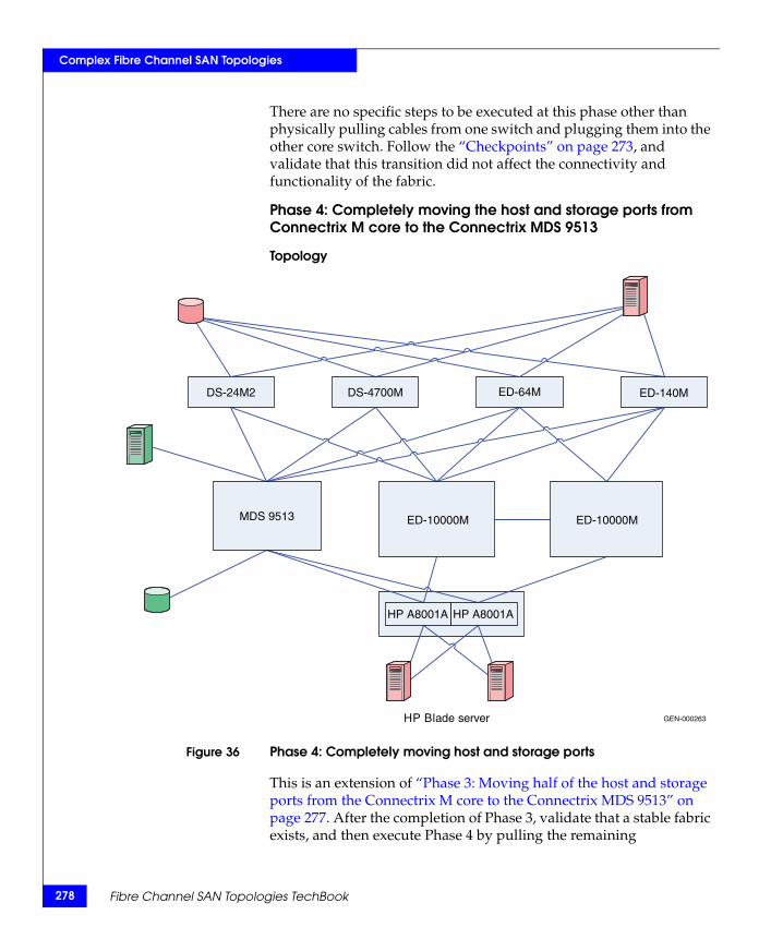
278
Complex Fibre Channel SAN Topologies
There are no specific steps to be executed at this phase other than physically pulling cables from one switch and plugging them into the other core switch. Follow the “Checkpoints” on page 273, and validate that this transition did not affect the connectivity and functionality of the fabric.
Phase 4: Completely moving the host and storage ports from Connectrix M core to the Connectrix MDS 9513
Topology
Figure 36 Phase 4: Completely moving host and storage ports
This is an extension of “Phase 3: Moving half of the host and storage ports from the Connectrix M core to the Connectrix MDS 9513” on page 277. After the completion of Phase 3, validate that a stable fabric exists, and then execute Phase 4 by pulling the remaining
HP Blade server
DS-24M2 DS-4700M ED-64M ED-140M
MDS 9513 ED-10000M ED-10000M
HP A8001A HP A8001A
GEN-000263
Fibre Channel SAN Topologies TechBook
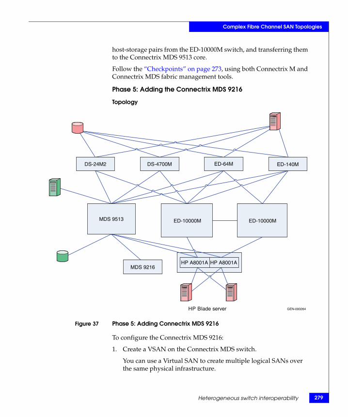
Complex Fibre Channel SAN Topologies
host-storage pairs from the ED-10000M switch, and transferring them to the Connectrix MDS 9513 core.
Follow the “Checkpoints” on page 273, using both Connectrix M and Connectrix MDS fabric management tools.
Phase 5: Adding the Connectrix MDS 9216
Topology
Figure 37 Phase 5: Adding Connectrix MDS 9216
To configure the Connectrix MDS 9216:
1. Create a VSAN on the Connectrix MDS switch.
You can use a Virtual SAN to create multiple logical SANs over the same physical infrastructure.
HP Blade server
DS-24M2
MDS 9216
DS-4700M ED-64M ED-140M
MDS 9513 ED-10000M ED-10000M
HP A8001A HP A8001A
GEN-000264
Heterogeneous switch interoperability 279
280
Complex Fibre Channel SAN Topologies
a. Click Create VSAN on Cisco Fabric Manager.
b. When the Create VSAN window appears, check the switches you want to include in this VSAN. In this case, only the Connectrix MDS 9513 is included.
c. Enter the VSAN ID with an unused ID number, and the VSAN name with an appropriate name. In this case study, VSAN ID number = 801 is assigned.
d. For VSAN attributes, leave all other field at default, except InterOperValue and AdminState. You can view VSAN attributes in the Information pane.
e. Set InterOperValue to Interop-1 and the AdminState to Suspended.
f. To statically assign VSAN membership for an interface using Fabric Manager select Interfaces > FC Physical from the Physical Attributes pane. The interface configuration appears in the Information pane. Select the General tab, double-click and then complete the PortVSAN field by entering the VSAN ID number (801) for every port you want the fabric to use.
For more details on VSAN settings and configuring the Interop-1 specific settings for Connectrix MDS 9000 family switches, refer to the documentation located at http://www.cisco.com.
2. To set port settings on the Device Manager for the Connectrix MDS 9513:
a. Select the desired switch, in this case, the Connectrix MDS 9513. The Device Manager for this switch appears.
b. Select the ports participating in this fabric and set the port speed to automax 2 G. Leave the other settings as default.
c. Set the Admin option to up.
3. Unsuspend the VSAN.
After configuring all the settings as stated above, go back to the VSAN attributes and change the AdminState to Active.
4. Link, using an ISL, the Connectrix MDS 9513 to all the Connectrix M edge switches as shown in Figure 37 on page 279.
Upon connecting these switches with matching VSAN IDs, the zoning information will merge. After executing the first four steps
Fibre Channel SAN Topologies TechBook
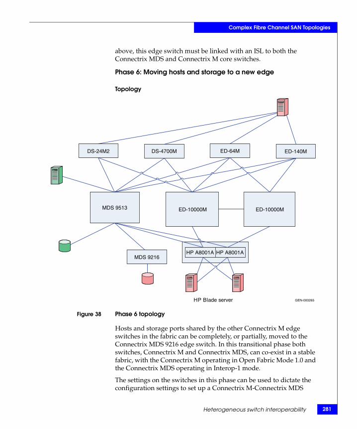
Complex Fibre Channel SAN Topologies
above, this edge switch must be linked with an ISL to both the Connectrix MDS and Connectrix M core switches.
Phase 6: Moving hosts and storage to a new edge
Topology
Figure 38 Phase 6 topology
Hosts and storage ports shared by the other Connectrix M edge switches in the fabric can be completely, or partially, moved to the Connectrix MDS 9216 edge switch. In this transitional phase both switches, Connectrix M and Connectrix MDS, can co-exist in a stable fabric, with the Connectrix M operating in Open Fabric Mode 1.0 and the Connectrix MDS operating in Interop-1 mode.
The settings on the switches in this phase can be used to dictate the configuration settings to set up a Connectrix M-Connectrix MDS
HP Blade server
DS-24M2
MDS 9216
DS-4700M ED-64M ED-140M
MDS 9513 ED-10000M ED-10000M
HP A8001A HP A8001A
GEN-000265
Heterogeneous switch interoperability 281
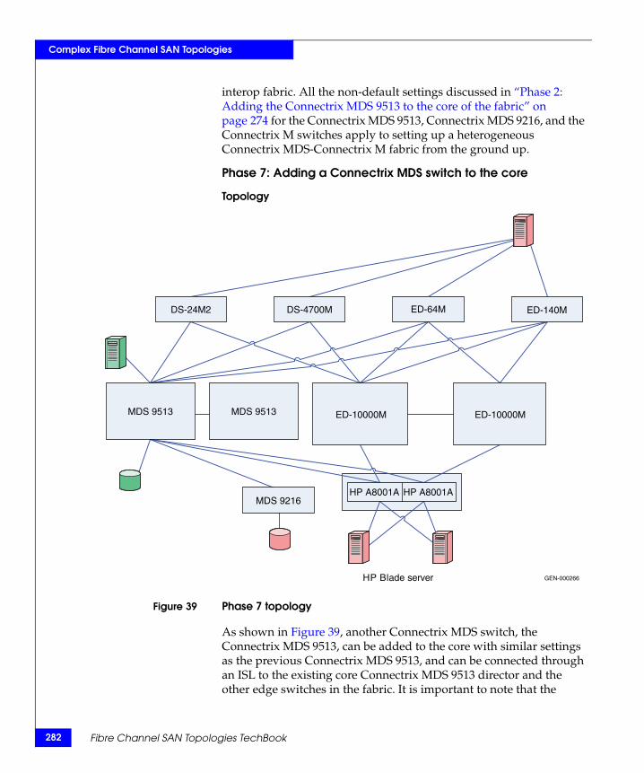
282
Complex Fibre Channel SAN Topologies
interop fabric. All the non-default settings discussed in “Phase 2: Adding the Connectrix MDS 9513 to the core of the fabric” on page 274 for the Connectrix MDS 9513, Connectrix MDS 9216, and the Connectrix M switches apply to setting up a heterogeneous Connectrix MDS-Connectrix M fabric from the ground up.
Phase 7: Adding a Connectrix MDS switch to the core
Topology
Figure 39 Phase 7 topology
As shown in Figure 39, another Connectrix MDS switch, the Connectrix MDS 9513, can be added to the core with similar settings as the previous Connectrix MDS 9513, and can be connected through an ISL to the existing core Connectrix MDS 9513 director and the other edge switches in the fabric. It is important to note that the
HP Blade server
DS-24M2
MDS 9216
DS-4700M ED-64M ED-140M
MDS 9513 MDS 9513 ED-10000M ED-10000M
HP A8001A HP A8001A
GEN-000266
Fibre Channel SAN Topologies TechBook
Complex Fibre Channel SAN Topologies
VSAN must be configured with the same VSAN ID and attributes as the existing VSAN to ensure a clean fabric merge.
Complete migration to Connectrix MDSAt the end of case study #2, a migration from a Connectrix M-only fabric to a Connectrix M-Connectrix MDS fabric with Connectrix MDS at the core, connected through ISLs to every edge switch in the fabric, occurred. The host and storage ports (except for the blade server host ports) can be completely moved over to the Connectrix MDS switches as specified in Phase 3, 4 and 6. The Connectrix M edge switches (except for the blade server Brocade M series switch modules) and the Connectrix M core switches can then be pulled out from the fabric. A fully operational Connectrix MDS-only fabric exists when completed. This is a complete migration from one switch vendor type (Brocade M series) to another vendor type (Cisco).
IMPORTANT!In a Connectrix MDS-only fabric, it is recommended to have all the Connectrix MDS switches operating in their native (default) mode. The Connectrix MDS switches at the end of the migration are in their interopmode.
In order to change the interopmode on the Connectrix MDS switches, it is not necessary to reboot the switches. The Interop mode attribute on the currently active VSANs needs to be changed from Interop-1 to Default.
The active zones that were pushed on to the Connectrix MDS switches from the Connectrix M switches, cannot be modified once this is done and the zoning needs to be reconfigured. It is highly recommended to take a backup of the configuration to avoid losing all the zoning information that was present in the active zoneset on the Connectrix MDS switches.
Warnings or caveatsPlease refer to EMC Knowledgebase solution emc149735 for all interop issues.
Heterogeneous switch interoperability 283
284
Complex Fibre Channel SAN Topologies
Case study #3 Migrating from a Connectrix B homogeneous fabric in Connectrix B native mode to a Connectrix MDS fabric
Assumptions specific to this case study:
◆ Interoperability mode settings on the switches are:
• Brocade native mode (interopmode 0) mode on the Connectrix B switches in the fabric.
• Cisco Interop-3 mode on the Connectrix MDS switches in the fabric.
◆ Fabric management applications used for managing the fabric:
• Cisco Fabric Manager, Brocade Web Tools.
Note: The Brocade Fabric Manager is not supported for management of a Connectrix B-Connectrix MDS heterogeneous fabric.
Fibre Channel SAN Topologies TechBook
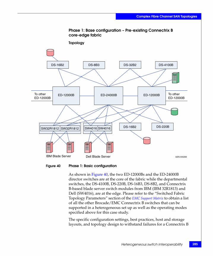
Complex Fibre Channel SAN Topologies
Phase 1: Base configuration – Pre-existing Connectrix B core-edge fabric
Topology
Figure 40 Phase 1: Basic configuration
As shown in Figure 40, the two ED-12000Bs and the ED-24000B director switches are at the core of the fabric while the departmental switches, the DS-4100B, DS-220B, DS-16B3, DS-8B2, and Connectrix B-based blade server switch modules from IBM (IBM 32R1813) and Dell (SW4016), are at the edge. Please refer to the “Switched Fabric Topology Parameters” section of the EMC Support Matrix to obtain a list of all the other Brocade/EMC Connectrix B switches that can be supported in a heterogeneous set up as well as the operating modes specified above for this case study.
The specific configuration settings, best practices, host and storage layouts, and topology design to withstand failures for a Connectrix B
GEN-000269
DS-16B2 DS-8B3 DS-32B2 DS-4100B
ED-12000B ED-12000BED-24000B
SW32R1812 SW32R1812 SW4016 SW4016 DS-16B2 DS-220B
IBM Blade Server Dell Blade Server
To otherED-12000B
To otherED-12000B
Heterogeneous switch interoperability 285
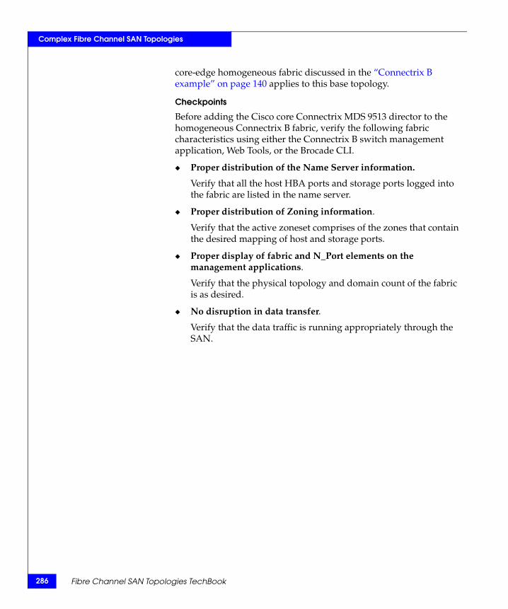
286
Complex Fibre Channel SAN Topologies
core-edge homogeneous fabric discussed in the “Connectrix B example” on page 140 applies to this base topology.
Checkpoints
Before adding the Cisco core Connectrix MDS 9513 director to the homogeneous Connectrix B fabric, verify the following fabric characteristics using either the Connectrix B switch management application, Web Tools, or the Brocade CLI.
◆ Proper distribution of the Name Server information.
Verify that all the host HBA ports and storage ports logged into the fabric are listed in the name server.
◆ Proper distribution of Zoning information.
Verify that the active zoneset comprises of the zones that contain the desired mapping of host and storage ports.
◆ Proper display of fabric and N_Port elements on the management applications.
Verify that the physical topology and domain count of the fabric is as desired.
◆ No disruption in data transfer.
Verify that the data traffic is running appropriately through the SAN.
Fibre Channel SAN Topologies TechBook
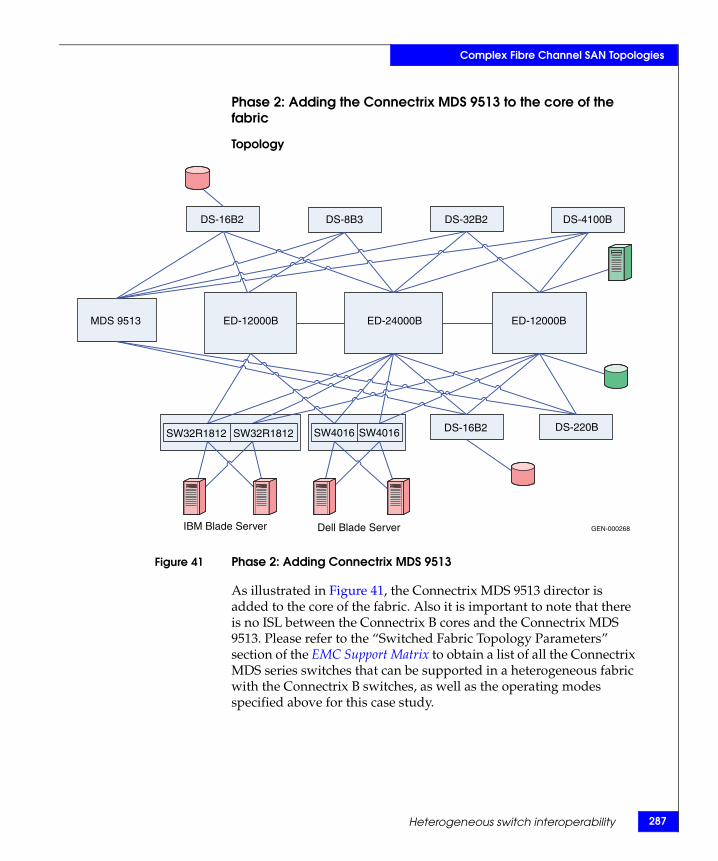
Complex Fibre Channel SAN Topologies
Phase 2: Adding the Connectrix MDS 9513 to the core of the fabric
Topology
Figure 41 Phase 2: Adding Connectrix MDS 9513
As illustrated in Figure 41, the Connectrix MDS 9513 director is added to the core of the fabric. Also it is important to note that there is no ISL between the Connectrix B cores and the Connectrix MDS 9513. Please refer to the “Switched Fabric Topology Parameters” section of the EMC Support Matrix to obtain a list of all the Connectrix MDS series switches that can be supported in a heterogeneous fabric with the Connectrix B switches, as well as the operating modes specified above for this case study.
GEN-000268
DS-16B2 DS-8B3 DS-32B2 DS-4100B
MDS 9513 ED-12000B ED-12000BED-24000B
SW32R1812 SW32R1812 SW4016 SW4016 DS-16B2 DS-220B
IBM Blade Server Dell Blade Server
Heterogeneous switch interoperability 287

288
Complex Fibre Channel SAN Topologies
Before adding the MDS 9513 to the fabric, the following steps need to be executed on the Connectrix MDS switch:
1. Create a VSAN on the Connectrix MDS switch.
A Virtual SAN can be used to create multiple logical SANs over the same physical infrastructure.
a. Click Create VSAN on the Cisco Fabric Manager.
b. When the Create VSAN window appears, check the switches that must be included in this VSAN. In this case, only the Connectrix MDS 9513 would be included.
c. Fill in the VSAN ID field with an unused ID number and the VSAN name filed with an appropriate name. In this case study, the VSAN ID number = 150 is assigned.
d. For the VSN attributes leave everything other than the InterOperValue and the AdminState at default.
e. Set InterOperValue to Interop-3 and the AdminState to Suspended.
f. Assign interfaces to the legacy switch interop mode 2 VSAN, i.e., statically assign VSAN membership for an interface using Fabric Manager, by selecting Interfaces > FC Physical from the Physical Attributes pane. The interface configuration in the Information pane appears. Click the General tab on this window and double-click and complete the PortVSAN field by entering the VSAN ID number (150) for every port desired to be used by this fabric.
For more details on the VSAN settings for Connectrix MDS 9000 Family switches refer to the Cisco document located at http://www.cisco.com.
For configuring Interop-3 specific settings on the Cisco CLI refer to the Cisco documentation located at http://www.cisco.com.
The legacy switch interoperability mode 3 for Connectrix B switches with more than 16 ports (and a core PID =1) was introduced with Connectrix MDS SAN-OS Release 1.3. With this VSAN-based interop mode, Connectrix B switches do not have to be altered from their native mode and can be seamlessly added to a new or existing Connectrix MDS SAN-OS VSAN.
Fibre Channel SAN Topologies TechBook
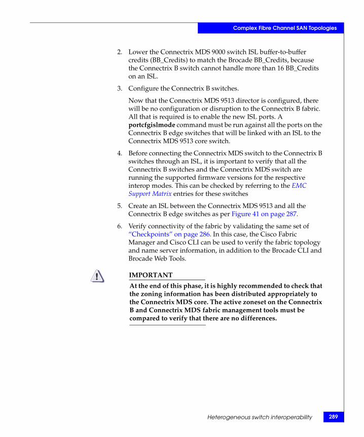
Complex Fibre Channel SAN Topologies
2. Lower the Connectrix MDS 9000 switch ISL buffer-to-buffer credits (BB_Credits) to match the Brocade BB_Credits, because the Connectrix B switch cannot handle more than 16 BB_Credits on an ISL.
3. Configure the Connectrix B switches.
Now that the Connectrix MDS 9513 director is configured, there will be no configuration or disruption to the Connectrix B fabric. All that is required is to enable the new ISL ports. A portcfgislmode command must be run against all the ports on the Connectrix B edge switches that will be linked with an ISL to the Connectrix MDS 9513 core switch.
4. Before connecting the Connectrix MDS switch to the Connectrix B switches through an ISL, it is important to verify that all the Connectrix B switches and the Connectrix MDS switch are running the supported firmware versions for the respective interop modes. This can be checked by referring to the EMC Support Matrix entries for these switches
5. Create an ISL between the Connectrix MDS 9513 and all the Connectrix B edge switches as per Figure 41 on page 287.
6. Verify connectivity of the fabric by validating the same set of “Checkpoints” on page 286. In this case, the Cisco Fabric Manager and Cisco CLI can be used to verify the fabric topology and name server information, in addition to the Brocade CLI and Brocade Web Tools.
IMPORTANT!At the end of this phase, it is highly recommended to check that the zoning information has been distributed appropriately to the Connectrix MDS core. The active zoneset on the Connectrix B and Connectrix MDS fabric management tools must be compared to verify that there are no differences.
Heterogeneous switch interoperability 289
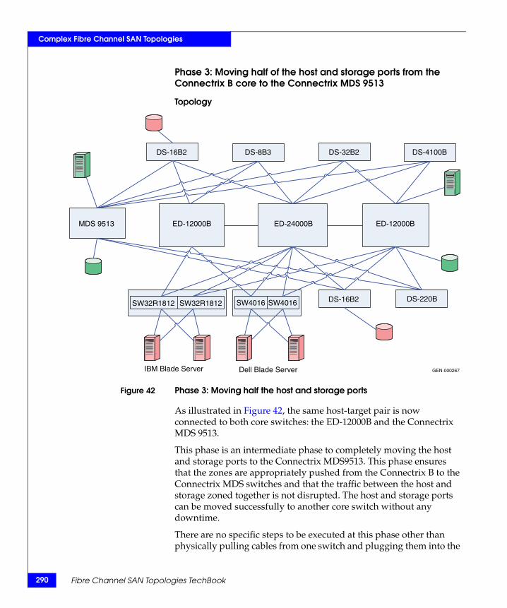
290
Complex Fibre Channel SAN Topologies
Phase 3: Moving half of the host and storage ports from the Connectrix B core to the Connectrix MDS 9513
Topology
Figure 42 Phase 3: Moving half the host and storage ports
As illustrated in Figure 42, the same host-target pair is now connected to both core switches: the ED-12000B and the Connectrix MDS 9513.
This phase is an intermediate phase to completely moving the host and storage ports to the Connectrix MDS9513. This phase ensures that the zones are appropriately pushed from the Connectrix B to the Connectrix MDS switches and that the traffic between the host and storage zoned together is not disrupted. The host and storage ports can be moved successfully to another core switch without any downtime.
There are no specific steps to be executed at this phase other than physically pulling cables from one switch and plugging them into the
GEN-000267
DS-16B2 DS-8B3 DS-32B2 DS-4100B
MDS 9513 ED-12000B ED-12000BED-24000B
SW32R1812 SW32R1812 SW4016 SW4016 DS-16B2 DS-220B
IBM Blade Server Dell Blade Server
Fibre Channel SAN Topologies TechBook
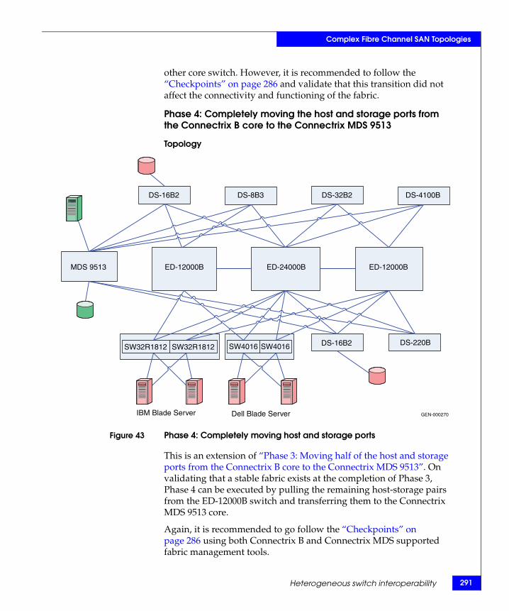
Complex Fibre Channel SAN Topologies
other core switch. However, it is recommended to follow the “Checkpoints” on page 286 and validate that this transition did not affect the connectivity and functioning of the fabric.
Phase 4: Completely moving the host and storage ports from the Connectrix B core to the Connectrix MDS 9513
Topology
Figure 43 Phase 4: Completely moving host and storage ports
This is an extension of “Phase 3: Moving half of the host and storage ports from the Connectrix B core to the Connectrix MDS 9513”. On validating that a stable fabric exists at the completion of Phase 3, Phase 4 can be executed by pulling the remaining host-storage pairs from the ED-12000B switch and transferring them to the Connectrix MDS 9513 core.
Again, it is recommended to go follow the “Checkpoints” on page 286 using both Connectrix B and Connectrix MDS supported fabric management tools.
GEN-000270
DS-16B2 DS-8B3 DS-32B2 DS-4100B
MDS 9513 ED-12000B ED-12000BED-24000B
SW32R1812 SW32R1812 SW4016 SW4016 DS-16B2 DS-220B
IBM Blade Server Dell Blade Server
Heterogeneous switch interoperability 291
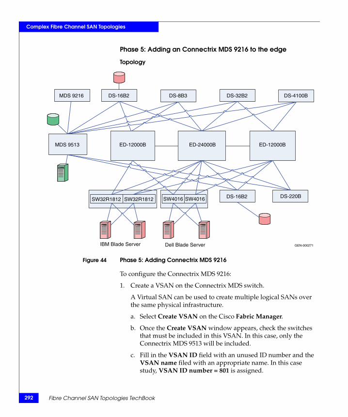
292
Complex Fibre Channel SAN Topologies
Phase 5: Adding an Connectrix MDS 9216 to the edge
Topology
Figure 44 Phase 5: Adding Connectrix MDS 9216
To configure the Connectrix MDS 9216:
1. Create a VSAN on the Connectrix MDS switch.
A Virtual SAN can be used to create multiple logical SANs over the same physical infrastructure.
a. Select Create VSAN on the Cisco Fabric Manager.
b. Once the Create VSAN window appears, check the switches that must be included in this VSAN. In this case, only the Connectrix MDS 9513 will be included.
c. Fill in the VSAN ID field with an unused ID number and the VSAN name filed with an appropriate name. In this case study, VSAN ID number = 801 is assigned.
GEN-000271
DS-16B2MDS 9216 DS-8B3 DS-32B2 DS-4100B
MDS 9513 ED-12000B ED-12000BED-24000B
SW32R1812 SW32R1812 SW4016 SW4016 DS-16B2 DS-220B
IBM Blade Server Dell Blade Server
Fibre Channel SAN Topologies TechBook
Complex Fibre Channel SAN Topologies
d. For VSAN attributes, leave everything other than the InterOperValue and the AdminState at default. VSAN attributes can be seen in the information pane.
e. Set InterOperValue to Interop-1 and the AdminState to Suspended.
f. Statically assign VSAN membership for an interface using Fabric Manager, by choosing Interfaces > FC Physical from the Physical Attributes pane. The interface configuration appears in the Information pane. Select the General tab on this window, and double-click and complete the PortVSAN field by entering the VSAN ID number (801) for every port desired to be used by this fabric.
For more details on the VSAN settings and for configuring the Interop-1 specific settings for Connectrix MDS 9000 family switches refer to the following Cisco documentation located at http://www.cisco.com.
2. To set port settings on the Device Manager for the Connectrix MDS 9513:
a. Select the desired switch, in this case, the Connectrix MDS 9513. The Device Manager for this switch appears.
b. Select the ports participating in this fabric, and then set the port speed to automax 2 G. Leave the other settings as default.
c. Set the Admin option to up.
3. Unsuspend the VSAN.
After configuring all the settings as stated above, go back to the VSAN attributes, and change the AdminState to Active.
4. Link, using an ISL, the Connectrix MDS 9513 to all the Connectrix M edge switches as shown in Figure 37 on page 279.
When connecting these switches with matching VSAN IDs, the zoning information merges. After executing the steps above, you must link this edge switch with an ISL to both the Connectrix MDS and Connectrix M core switches.
Heterogeneous switch interoperability 293
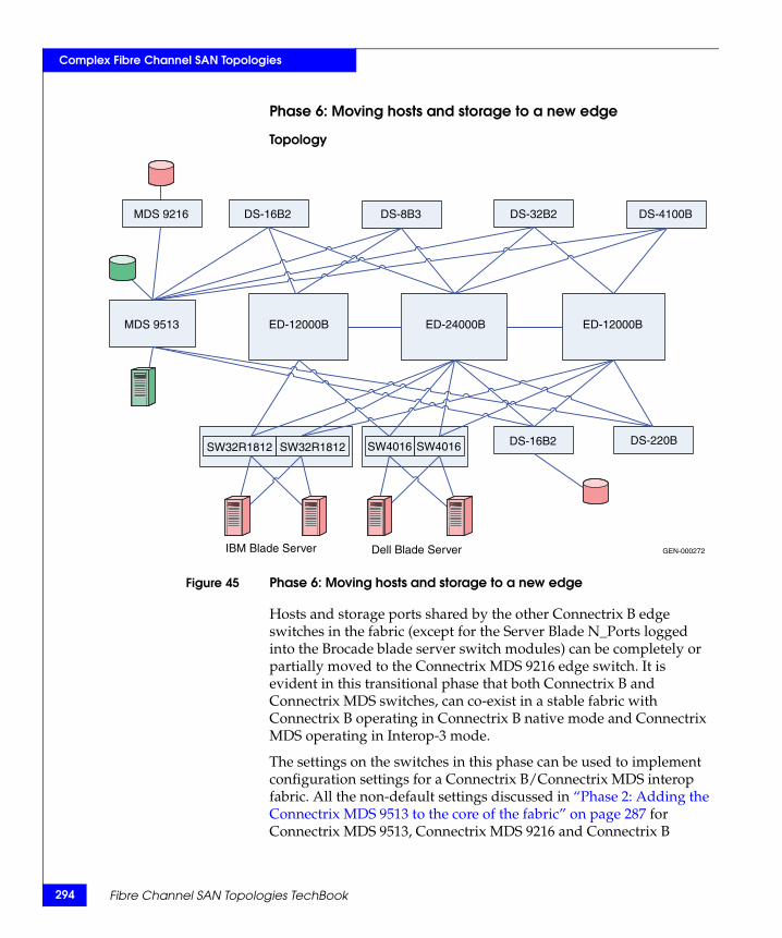
294
Complex Fibre Channel SAN Topologies
Phase 6: Moving hosts and storage to a new edge
Topology
Figure 45 Phase 6: Moving hosts and storage to a new edge
Hosts and storage ports shared by the other Connectrix B edge switches in the fabric (except for the Server Blade N_Ports logged into the Brocade blade server switch modules) can be completely or partially moved to the Connectrix MDS 9216 edge switch. It is evident in this transitional phase that both Connectrix B and Connectrix MDS switches, can co-exist in a stable fabric with Connectrix B operating in Connectrix B native mode and Connectrix MDS operating in Interop-3 mode.
The settings on the switches in this phase can be used to implement configuration settings for a Connectrix B/Connectrix MDS interop fabric. All the non-default settings discussed in “Phase 2: Adding the Connectrix MDS 9513 to the core of the fabric” on page 287 for Connectrix MDS 9513, Connectrix MDS 9216 and Connectrix B
GEN-000272
DS-16B2MDS 9216 DS-8B3 DS-32B2 DS-4100B
MDS 9513 ED-12000B ED-12000BED-24000B
SW32R1812 SW32R1812 SW4016 SW4016 DS-16B2 DS-220B
IBM Blade Server Dell Blade Server
Fibre Channel SAN Topologies TechBook
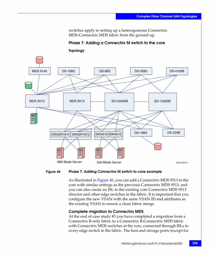
Complex Fibre Channel SAN Topologies
switches apply to setting up a heterogeneous Connectrix MDS-Connectrix MDS fabric from the ground up.
Phase 7: Adding a Connectrix M switch to the core
Topology
Figure 46 Phase 7: Adding Connectrix M switch to core example
As illustrated in Figure 46, you can add a Connectrix MDS 9513 to the core with similar settings as the previous Connectrix MDS 9513, and you can also create an ISL to the existing core Connectrix MDS 9513 director and other edge switches in the fabric. It is important that you configure the new VSAN with the same VSAN ID and attributes as the existing VSAN to ensure a clean fabric merge.
Complete migration to Connectrix MDSAt the end of case study #3 you have completed a migration from a Connectrix B-only fabric to a Connectrix B-Connectrix MDS fabric with Connectrix MDS switches at the core, connected through ISLs to every edge switch in the fabric. The host and storage ports (except for
GEN-000273
DS-16B2MDS 9140 DS-8B3 DS-32B2 DS-4100B
MDS 9513 MDS 9513 ED-12000BED-24000B
SW32R1812 SW32R1812 SW4016 SW4016 DS-16B2 DS-220B
IBM Blade Server Dell Blade Server
Heterogeneous switch interoperability 295
296
Complex Fibre Channel SAN Topologies
the blade server host ports) can be completely moved to the Connectrix MDS switches as specified in Phase 3, 4 and 6. The Connectrix B edge switches (except for the blade server Brocade switch modules) and the Connectrix B core switches can now be pulled out of the fabric. A fully operational Connectrix MDS-only fabric now exists. This is a complete migration from one switch type (Connectrix B) to another type (Connectrix MDS).
IMPORTANT!In a Connectrix MDS-only fabric, it is recommended that all Connectrix MDS switches operate in their native (default) mode. Connectrix MDS switches are in interopmode at the end of the migration.
You need not reboot the switch to change the interopmode on a Connectrix MDS. The Interop mode attribute on currently active VSANs must be changed from Interop-3 to Default.
You cannot modify active zones that were pushed to Connectrix MDS switches from Connectrix B switches; zoning must be reconfigured. It is highly recommended that you backup the configuration to avoid losing all zoning information in the active zoneset on the Connectrix MDS switches.
Warnings or caveatsConsider the following:
◆ Refer to EMC Knowledgebase solution emc149735 for all interop issues.
◆ In MDS interop mode 3 and Brocade Native mode, a host attached to a Brocade switch does not receive RSCN after zoneset activation/de-activation and therefore will not immediately discover newly added LUNs. Zoneset activation scenarios include a new zoneset activation and modification of existing zoneset and reactivation. A zoneset may be a regular zoneset or an IVR zoneset. This issue is seen on EMC-supported Brocade releases: v5.3.x; v6.1.x. The workaround is to bounce (disable and enable) the host port attached to Brocade switches after zoneset activation in order to update the devices. (Only the Host port that added the new target port needs to be bounced.)
◆ Zoning changes cannot be activated froma Brocade switch. The workaround is to use MDS switches to activate zoning changes. This caveat is specific to EMC-supported Brocade FOS v6.1.x.
Fibre Channel SAN Topologies TechBook
Complex Fibre Channel SAN Topologies
Case Study #4 Setting up a heterogeneous switched fabric with Connectrix B switches in the interop mode (interopmode 1), and the Connectrix MDS switches in Interop-1 mode
Assumptions specific to this case study:
◆ Interoperability mode settings on the switches:
• Interop mode: interopmode 1 on the Connectrix B switches in the fabric.
• Cisco Interop-1 mode on the Connectrix MDS switches in the fabric.
◆ Fabric management applications used for managing the fabric:
• Cisco Fabric Manager• Web Tools only for Connectrix B switches
IMPORTANT!Brocade's interopmode 1 has been replaced with interopmode 3 on Brocade FOS v6.0.x and higher. Therefore, if the Brocade switch is running FOS v6.0.x or higher, the following assumptions will apply to this case study:
For Interoperability mode settings on the switches: – Interop mode: interopmode 3 on the Connectrix B switches
in the fabric – Cisco Interop-1 mode on the Connectrix MDS switches in the
fabric
For Fabric management applications used for managing the fabric: – Cisco Fabric Manager – Web Tools only for Connectrix B switches
Refer to the EMC Support Matrix for the latest supported firmware versions on the Cisco MDS switches for interop with Brocade/Connectrix B switches running FOS v6.0.x and higher.
When migrating from a Connectrix B to a Connectrix MDS fabric, keep the fabric in Connectrix B native mode and follow the migration process explained in “Case study #3” on page 284. This case study shows the settings that you must configure on Connectrix B and Connectrix MDS switches before they are linked with an ISL. This is a required step when migrating from a Connectrix B to a Connectrix MDS fabric.
Heterogeneous switch interoperability 297
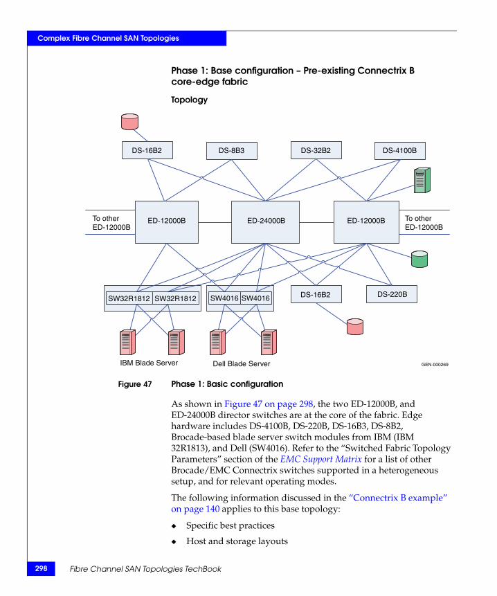
298
Complex Fibre Channel SAN Topologies
Phase 1: Base configuration – Pre-existing Connectrix B core-edge fabric
Topology
Figure 47 Phase 1: Basic configuration
As shown in Figure 47 on page 298, the two ED-12000B, and ED-24000B director switches are at the core of the fabric. Edge hardware includes DS-4100B, DS-220B, DS-16B3, DS-8B2, Brocade-based blade server switch modules from IBM (IBM 32R1813), and Dell (SW4016). Refer to the “Switched Fabric Topology Parameters” section of the EMC Support Matrix for a list of other Brocade/EMC Connectrix switches supported in a heterogeneous setup, and for relevant operating modes.
The following information discussed in the “Connectrix B example” on page 140 applies to this base topology:
◆ Specific best practices
◆ Host and storage layouts
GEN-000269
DS-16B2 DS-8B3 DS-32B2 DS-4100B
ED-12000B ED-12000BED-24000B
SW32R1812 SW32R1812 SW4016 SW4016 DS-16B2 DS-220B
IBM Blade Server Dell Blade Server
To otherED-12000B
To otherED-12000B
Fibre Channel SAN Topologies TechBook
Complex Fibre Channel SAN Topologies
◆ Design to withstand failures for a Connectrix B core-edge homogeneous fabric
This case study, unlike “Case study #3” on page 284, sets Connectrix B switches to interop mode, links them with an ISL to Connectrix MDS switches (operating in their supported Interop-1 mode), and then pulls out the Connectrix B cores from the fabric.
Since this is a Connectrix B-only fabric with all switches operating in Connectrix B native mode by default, the following non-default settings must be configured on the Connectrix B switches using the Brocade CLI:
1. Telnet into all the Connectrix B switches in the fabric; one at a time.
2. Run the interopmode command at the switch command prompt.
3. If interopmode is On, the switch can become part of a fabric that can accept the addition of a Connectrix MDS. If it is Off, perform Step 4 through Step 8.
4. Disable the switch by running the switchdisable command at the switch prompt.
5. Issue the interopmode 1 command.
6. Enter a confirmation yes: y to switch the interopmode to on. Enter y in the warning box.
7. Reboot the switch to activate configuration settings.
8. After reboot, repeat Step 1 through Step 3 to verify that interopmode has been set to On.
9. Run the version command to verify that the switch is running the supported firmware version for interop with Connectrix MDS.
10. The msplmgmtdeactivate command must explicitly be run prior to connecting from a Connectrix B switch to a Connectrix MDS 9000 Family switch.
Checkpoints
Before adding the Connectrix MDS core Connectrix MDS 9513 director to the Connectrix B fabric, verify the following fabric characteristics using either the Brocade switch management application, Web Tools, or the Brocade CLI.
◆ Proper distribution of the Name Server information.
Heterogeneous switch interoperability 299
300
Complex Fibre Channel SAN Topologies
Verify that the all host HBA ports and storage ports that are logged into the fabric are listed in the name server.
◆ Proper distribution of Zoning information.
Verify that the active zoneset comprises zones that contain the desired mapping of host and storage ports.
◆ Proper display of fabric and N_Port elements on the management applications.
Verify that the physical topology and domain count of the fabric are correct.
◆ No disruption in data transfer.
Verify that the data traffic is running appropriately through the SAN.
Fibre Channel SAN Topologies TechBook
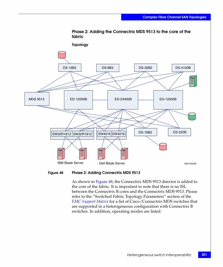
Complex Fibre Channel SAN Topologies
Phase 2: Adding the Connectrix MDS 9513 to the core of the fabric
Topology
Figure 48 Phase 2: Adding Connectrix MDS 9513
As shown in Figure 48, the Connectrix MDS 9513 director is added to the core of the fabric. It is important to note that there is no ISL between the Connectrix B cores and the Connectrix MDS 9513. Please refer to the “Switched Fabric Topology Parameters” section of the EMC Support Matrix for a list of Cisco/Connectrix MDS switches that are supported in a heterogeneous configuration with Connectrix B switches. In addition, operating modes are listed.
GEN-000268
DS-16B2 DS-8B3 DS-32B2 DS-4100B
MDS 9513 ED-12000B ED-12000BED-24000B
SW32R1812 SW32R1812 SW4016 SW4016 DS-16B2 DS-220B
IBM Blade Server Dell Blade Server
Heterogeneous switch interoperability 301
302
Complex Fibre Channel SAN Topologies
Before adding a Connectrix MDS 9513 to the fabric, follow these steps for a Connectrix MDS switch:
1. Create a VSAN on the Connectrix MDS.
A Virtual SAN can be used to create multiple logical SANs over the same physical infrastructure.
a. Click Create VSAN on the Cisco Fabric Manager.
b. When the Create VSAN window appears, check the switches you want to include in the VSAN. In this case, only Connectrix MDS 9513 switches are included.
c. Fill in the VSAN ID field with an unused ID number, and the VSAN name field with an appropriate name. In this case study, the VSAN ID number = 801 is assigned.
d. For VSAN attributes, leave everything other than the InterOperValue and the AdminState at default. VSAN attributes can be seen in the information pane.
e. Set InterOperValue to Interop-1 and the AdminState to Suspended.
f. Statically assign VSAN membership for an interface using Fabric Manager, by choosing Interfaces > FC Physical from the Physical Attributes pane. The interface configuration appears in the Information pane. Select the General tab.
g. Double-click and complete the PortVSAN field by entering the VSAN ID number (801) for every port that will be used by this fabric.
For more details on VSAN settings and for configuring Interop-1 specific settings for Connectrix MDS 9000 Family switches, refer to the documentation located at http://www.cisco.com.
2. Set port settings on the Device Manager for the Connectrix MDS 9513:
a. Select the desired switch, in this case the Connectrix MDS 9513.The Device Manager for this switch displays.
b. Select the ports participating in this fabric and set the port speed to automax 2 G. Leave the other settings as default.
Fibre Channel SAN Topologies TechBook
Complex Fibre Channel SAN Topologies
c. Set the Admin option to up.
3. Unsuspend the VSAN.
After configuring all the settings as stated above, go back to the VSAN attributes and change the AdminState to Active.
4. Using an ISL, link the Connectrix MDS 9513 to all of the Connectrix B edge switches that appear in the topology diagram.
5. Verify connectivity of the fabric by validating the same set of “Checkpoints” on page 299. In this case, the Cisco Fabric Manager and Cisco CLI can be used to verify the fabric topology and name server information.
IMPORTANT!At the end of this procedure, make sure the zoning information was distributed appropriately to the Connectrix MDS core. Compare the active zoneset on the Connectrix B and Connectrix MDS fabric management tools to verify that no differences exist.
Heterogeneous switch interoperability 303
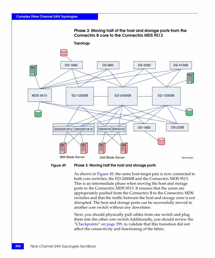
304
Complex Fibre Channel SAN Topologies
Phase 3: Moving half of the host and storage ports from the Connectrix B core to the Connectrix MDS 9513
Topology
Figure 49 Phase 3: Moving half the host and storage ports
As shown in Figure 49, the same host-target pair is now connected to both core switches: the ED-24000B and the Connectrix MDS 9513. This is an intermediate phase when moving the host and storage ports to the Connectrix MDS 9513. It ensures that the zones are appropriately pushed from the Connectrix B to the Connectrix MDS switches and that the traffic between the host and storage zone is not disrupted. The host and storage ports can be successfully moved to another core switch without any downtime.
Next, you should physically pull cables from one switch and plug them into the other core switch.Additionally, you should review the “Checkpoints” on page 299, to validate that this transition did not affect the connectivity and functioning of the fabric.
GEN-000267
DS-16B2 DS-8B3 DS-32B2 DS-4100B
MDS 9513 ED-12000B ED-12000BED-24000B
SW32R1812 SW32R1812 SW4016 SW4016 DS-16B2 DS-220B
IBM Blade Server Dell Blade Server
Fibre Channel SAN Topologies TechBook
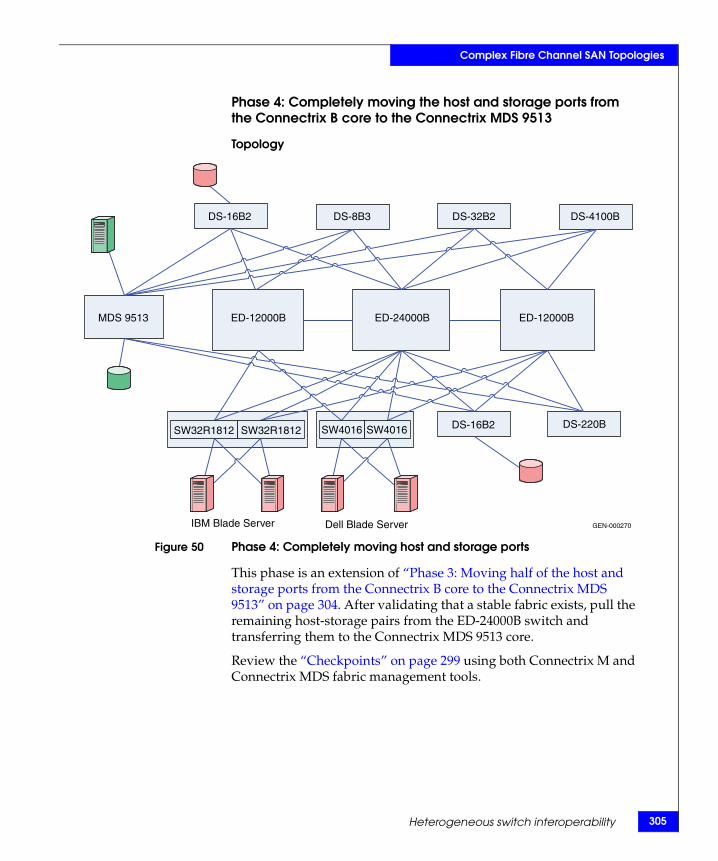
Complex Fibre Channel SAN Topologies
Phase 4: Completely moving the host and storage ports from the Connectrix B core to the Connectrix MDS 9513
Topology
Figure 50 Phase 4: Completely moving host and storage ports
This phase is an extension of “Phase 3: Moving half of the host and storage ports from the Connectrix B core to the Connectrix MDS 9513” on page 304. After validating that a stable fabric exists, pull the remaining host-storage pairs from the ED-24000B switch and transferring them to the Connectrix MDS 9513 core.
Review the “Checkpoints” on page 299 using both Connectrix M and Connectrix MDS fabric management tools.
GEN-000270
DS-16B2 DS-8B3 DS-32B2 DS-4100B
MDS 9513 ED-12000B ED-12000BED-24000B
SW32R1812 SW32R1812 SW4016 SW4016 DS-16B2 DS-220B
IBM Blade Server Dell Blade Server
Heterogeneous switch interoperability 305
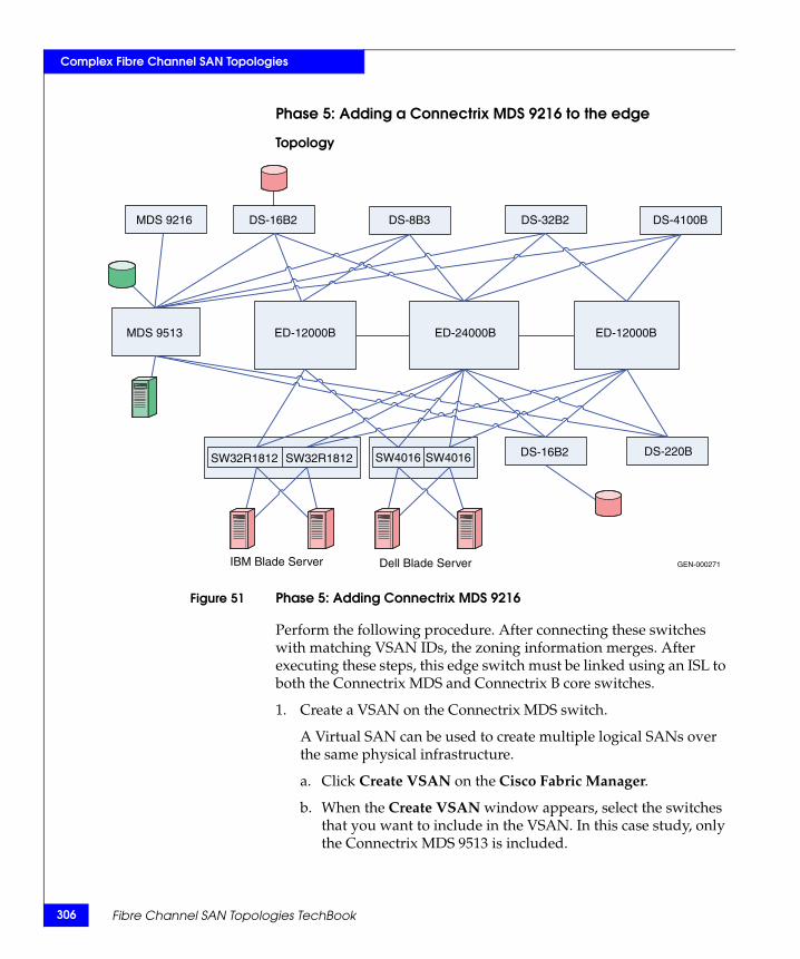
306
Complex Fibre Channel SAN Topologies
Phase 5: Adding a Connectrix MDS 9216 to the edge
Topology
Figure 51 Phase 5: Adding Connectrix MDS 9216
Perform the following procedure. After connecting these switches with matching VSAN IDs, the zoning information merges. After executing these steps, this edge switch must be linked using an ISL to both the Connectrix MDS and Connectrix B core switches.
1. Create a VSAN on the Connectrix MDS switch.
A Virtual SAN can be used to create multiple logical SANs over the same physical infrastructure.
a. Click Create VSAN on the Cisco Fabric Manager.
b. When the Create VSAN window appears, select the switches that you want to include in the VSAN. In this case study, only the Connectrix MDS 9513 is included.
GEN-000271
DS-16B2MDS 9216 DS-8B3 DS-32B2 DS-4100B
MDS 9513 ED-12000B ED-12000BED-24000B
SW32R1812 SW32R1812 SW4016 SW4016 DS-16B2 DS-220B
IBM Blade Server Dell Blade Server
Fibre Channel SAN Topologies TechBook
Complex Fibre Channel SAN Topologies
c. Fill in the VSAN ID field with an unused ID number and the VSAN name field with an appropriate name. In this case study, the VSAN ID number = 801 is assigned.
d. For VSAN attributes, leave everything other than the InterOperValue and the AdminState at default. VSAN attributes can be seen in the Information pane.
e. Set InterOperValue to Interop-1 and the AdminState to Suspended.
f. Statically assign VSAN membership for an interface using Fabric Manager, by selecting Interfaces > FC Physical from the Physical Attributes pane. The interface configuration appears in the Information pane.
g. Select the General tab on this window, double-click and complete the PortVSAN field by entering the VSAN ID number (801) for every port desired for this fabric.
For more details on VSAN settings and for information on configuring the Interop-1 specific settings for Connectrix MDS 9000 Family switches refer to the documentation located at http://www.cisco.com.
2. Set port settings on the Device Manager for the Connectrix MDS 9513:
a. Select the desired switch, in this case the Connectrix MDS 9513. The Device Manager for this switch appears.
b. Select the ports participating in this fabric, and then set the port speed to automax 2 G. Leave the other settings as default.
c. Set the Admin option to up.
3. Unsuspend the VSAN.
After configuring all the settings as stated above, go back to the VSAN attributes and change the AdminState to Active.
4. Link, using an ISL, the Connectrix MDS 9513 to all the Connectrix B edge switches referring to the topology diagram.
After connecting these switches with matching VSAN IDs, the zoning information merges. After executing the steps above, this edge switch must be linked with an ISL to both the Connectrix MDS and Connectrix M core switches.
Heterogeneous switch interoperability 307
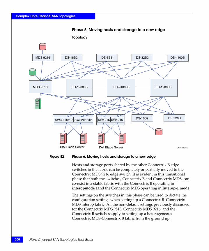
308
Complex Fibre Channel SAN Topologies
Phase 6: Moving hosts and storage to a new edge
Topology
Figure 52 Phase 6: Moving hosts and storage to a new edge
Hosts and storage ports shared by the other Connectrix B edge switches in the fabric can be completely or partially moved to the Connectrix MDS 9216 edge switch. It is evident in this transitional phase that both the switches, Connectrix B and Connectrix MDS, can co-exist in a stable fabric with the Connectrix B operating in interopmode 1and the Connectrix MDS operating in Interop-1 mode.
The settings on the switches in this phase can be used to dictate the configuration settings when setting up a Connectrix B–Connectrix MDS interop fabric. All the non-default settings previously discussed for the Connectrix MDS 9513, Connectrix MDS 9216, and the Connectrix B switches apply to setting up a heterogeneous Connectrix MDS-Connectrix B fabric from the ground up.
GEN-000272
DS-16B2MDS 9216 DS-8B3 DS-32B2 DS-4100B
MDS 9513 ED-12000B ED-12000BED-24000B
SW32R1812 SW32R1812 SW4016 SW4016 DS-16B2 DS-220B
IBM Blade Server Dell Blade Server
Fibre Channel SAN Topologies TechBook
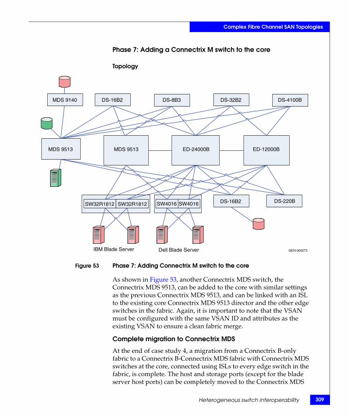
Complex Fibre Channel SAN Topologies
Phase 7: Adding a Connectrix M switch to the core
Topology
Figure 53 Phase 7: Adding Connectrix M switch to the core
As shown in Figure 53, another Connectrix MDS switch, the Connectrix MDS 9513, can be added to the core with similar settings as the previous Connectrix MDS 9513, and can be linked with an ISL to the existing core Connectrix MDS 9513 director and the other edge switches in the fabric. Again, it is important to note that the VSAN must be configured with the same VSAN ID and attributes as the existing VSAN to ensure a clean fabric merge.
Complete migration to Connectrix MDS
At the end of case study 4, a migration from a Connectrix B-only fabric to a Connectrix B-Connectrix MDS fabric with Connectrix MDS switches at the core, connected using ISLs to every edge switch in the fabric, is complete. The host and storage ports (except for the blade server host ports) can be completely moved to the Connectrix MDS
GEN-000273
DS-16B2MDS 9140 DS-8B3 DS-32B2 DS-4100B
MDS 9513 MDS 9513 ED-12000BED-24000B
SW32R1812 SW32R1812 SW4016 SW4016 DS-16B2 DS-220B
IBM Blade Server Dell Blade Server
Heterogeneous switch interoperability 309
310
Complex Fibre Channel SAN Topologies
switches as specified in Phase 3 (refer to “Phase 3: Moving half of the host and storage ports from the Connectrix B core to the Connectrix MDS 9513” on page 304), Phase 4 (refer to “Phase 4: Completely moving the host and storage ports from the Connectrix B core to the Connectrix MDS 9513” on page 305) and Phase 6 (refer to “Phase 6: Moving hosts and storage to a new edge” on page 308). The Connectrix B edge switches (except for the blade server Brocade switch modules), and the Connectrix B core switches can then be pulled out from the fabric. This results in a fully operational Cisco-only fabric. This is a complete migration from one switch type (Connectrix B) to another type (Connectrix MDS).
IMPORTANT!In a Connectrix MDS-only fabric, all the Connectrix MDS switches should operate in native (default) mode. The Connectrix MDS switches are in interopmode at the end of the migration.
You need not reboot Connectrix MDS switches to change the interopmode. The Interop mode attribute on the currently active VSANs must be changed from Interop-1 to Default.
However, the active zones that were pushed on to the Connectrix MDS from the Connectrix M switches cannot be modified once the interopmode on the Connectrix MDS is changed. Zoning must be reconfigured. It is highly recommended that you backup the configuration to avoid losing all zoning information that was present in the active zoneset for Connectrix MDS switches.
Warnings or caveatsConsider the following:
◆ Please refer to EMC Knowledgebase solution emc149735 for all interoperability issues.
◆ Zoning changes cannot be activated froma Brocade switch. The workaround is to use MDS switches to activate zoning changes. This caveat is specific to EMC-supported Brocade FOS v6.1.x.
Fibre Channel SAN Topologies TechBook
Complex Fibre Channel SAN Topologies
Case study #5: Migrating from a Connectrix M homogeneous fabric in Open Fabric 1.0 mode to a Brocade fabric.
Assumptions specific to this case study:
◆ Interoperability mode settings on the switches are:
• Brocade M series Open Fabric mode 1.0 on the Brocade M series switches in the fabric.
• Connectrix B interop mode (interopmode 1) mode on the Connectrix B switches in the fabric.
◆ Fabric management applications used for managing the fabric:
• The Connectrix Manager is used to manage the fabric.
Note: The Brocade Fabric Manager and Web Tools cannot be used for management of a Connectrix B-Connectrix M heterogeneous fabric.Web Tools can be used to change the switch settings on the Connectrix B.
IMPORTANT!Brocade's interopmode 1 has been replaced with interopmode 3 on Brocade FOS v6.0.x and higher. Therefore, if the Brocade switch is running FOS v6.0.x or higher, the following assumptions will apply to this case study.
Interoperability mode settings on the switches:– Interop mode: interopmode 3 on the Connectrix B switches in the
fabric– Open Fabric mode 1.0 on the Brocade M series switches in the
fabric
Fabric management applications used for managing the fabric:– Connectrix Manager Data Center Edition (CMDCE) can be used to
manage a heterogeneous fabric comprising of Connectrix B and Connecrix M series switches.
– Web Tools can be used to change the switch settings on the Connectrix B switches.
Refer to the EMC Support Matrix for the latest supported firmware versions on the Connectrix M series switches for interop with Brocade/Connectrix B switches running FOS v6.0.x and higher.
Heterogeneous switch interoperability 311
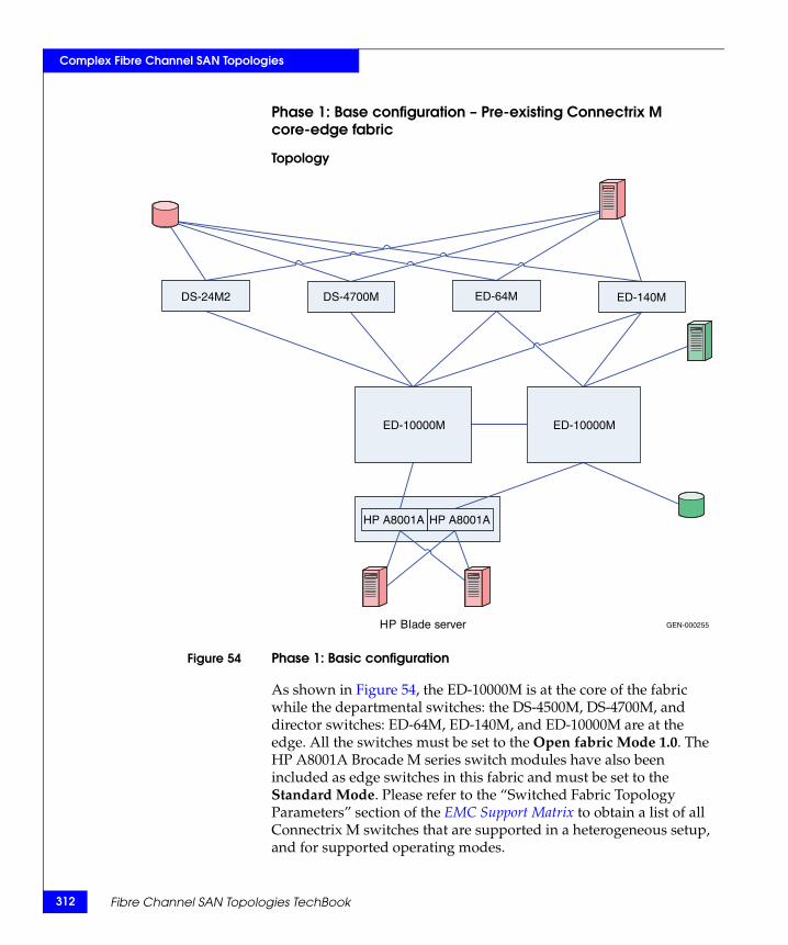
312
Complex Fibre Channel SAN Topologies
Phase 1: Base configuration – Pre-existing Connectrix M core-edge fabric
Topology
Figure 54 Phase 1: Basic configuration
As shown in Figure 54, the ED-10000M is at the core of the fabric while the departmental switches: the DS-4500M, DS-4700M, and director switches: ED-64M, ED-140M, and ED-10000M are at the edge. All the switches must be set to the Open fabric Mode 1.0. The HP A8001A Brocade M series switch modules have also been included as edge switches in this fabric and must be set to the Standard Mode. Please refer to the “Switched Fabric Topology Parameters” section of the EMC Support Matrix to obtain a list of all Connectrix M switches that are supported in a heterogeneous setup, and for supported operating modes.
HP Blade server
DS-24M2 DS-4700M ED-64M ED-140M
ED-10000M ED-10000M
HP A8001A HP A8001A
GEN-000255
Fibre Channel SAN Topologies TechBook
Complex Fibre Channel SAN Topologies
Specific configuration settings, best practices, host and storage layouts, and topology design that can withstand failures for a Brocade M series core-edge homogeneous fabric, were discussed in the “Connectrix M example” on page 163. These settings apply to the base topology in this case study.
Checkpoints
Before adding the ED-24000B switch to the homogeneous Brocade M series fabric, verify that the following fabric characteristics exist. Use either the McDATA Connectrix Manager or the McDATA CLI.
◆ Proper distribution of Name Server information.
Verify that the all host (standalone and server blade) HBA and storage ports that are logged into the fabric appear in the name server.
◆ Proper distribution of Zoning information.
Verify that the active zoneset consists of the zones containing the desired mapping of host and storage ports.
◆ Proper display of fabric and N_Port elements on the management applications.
Verify that the physical topology and domain count of the fabric is correct.
◆ No disruption in data transfer.
Verify that data traffic is running appropriately through the SAN.
Heterogeneous switch interoperability 313
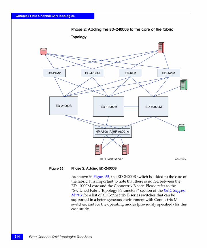
314
Complex Fibre Channel SAN Topologies
Phase 2: Adding the ED-24000B to the core of the fabric
Topology
Figure 55 Phase 2: Adding ED-24000B
As shown in Figure 55, the ED-24000B switch is added to the core of the fabric. It is important to note that there is no ISL between the ED-10000M core and the Connectrix B core. Please refer to the “Switched Fabric Topology Parameters” section of the EMC Support Matrix for a list of all Connectrix B series switches that can be supported in a heterogeneous environment with Connectrix M switches, and for the operating modes (previously specified) for this case study.
HP Blade server
DS-24M2 DS-4700M ED-64M ED-140M
ED-24000B ED-10000M ED-10000M
HP A8001A HP A8001A
GEN-000254
Fibre Channel SAN Topologies TechBook
Complex Fibre Channel SAN Topologies
Before adding the ED-24000B to the fabric, follow these steps for the Connectrix B switch:
1. Telnet into the ED-24000B.
2. Run the interopmode command at the switch command prompt.
3. If interopmode is On, the switch is ready to be a part of a fabric where a Cisco switch will be added. If it is Off, execute Step 4 through Step 8.
4. Disable the switch by running the switchdisable command at the switch prompt.
5. Issue the interopmode 1 command.
6. Enter a confirmation yes: y to switch the interopmode to On.A warning appears.Enter y to continue.
7. Reboot the switch to implement configuration settings.
8. After reboot, repeat Step 1 through Step 3 to verify that interopmode was set to On.
9. Run the version command at the switch command prompt to verify that the switch is running the supported firmware version for interop with Connectrix M.
10. The msplmgmtdeactivate command must be run prior to connecting from a Connectrix B switch to a Connectrix M switch.
IMPORTANT!At the end of this phase of the case study, make sure the zoning information was distributed appropriately to the Connectrix B core.
Note: Unlike the Connectrix B-Connectrix MDS interop where the active zoneset or Effective Configuration in Connectrix B terminology gets pushed into Connectrix B Defined Configuration, the active zoneset from Connectrix M is not pushed into Connectrix B Defined Configuration. Therefore no zoning edits or changes can be made using Connectrix B switch management applications in a Connectrix B-Connectrix M interop environment.
“Checkpoints” on page 313 must be revisited at the end of this phase to verify that the name server information distribution and other fabric parameters based on this topology have been distributed appropriately.
Heterogeneous switch interoperability 315
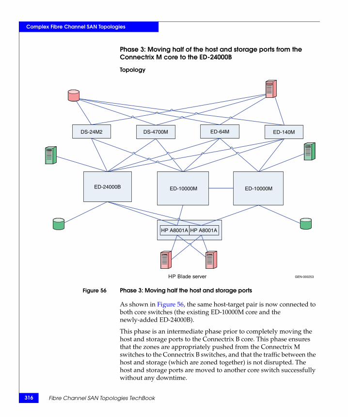
316
Complex Fibre Channel SAN Topologies
Phase 3: Moving half of the host and storage ports from the Connectrix M core to the ED-24000B
Topology
Figure 56 Phase 3: Moving half the host and storage ports
As shown in Figure 56, the same host-target pair is now connected to both core switches (the existing ED-10000M core and the newly-added ED-24000B).
This phase is an intermediate phase prior to completely moving the host and storage ports to the Connectrix B core. This phase ensures that the zones are appropriately pushed from the Connectrix M switches to the Connectrix B switches, and that the traffic between the host and storage (which are zoned together) is not disrupted. The host and storage ports are moved to another core switch successfully without any downtime.
HP Blade server
DS-24M2 DS-4700M ED-64M ED-140M
ED-24000B ED-10000M ED-10000M
HP A8001A HP A8001A
GEN-000253
Fibre Channel SAN Topologies TechBook
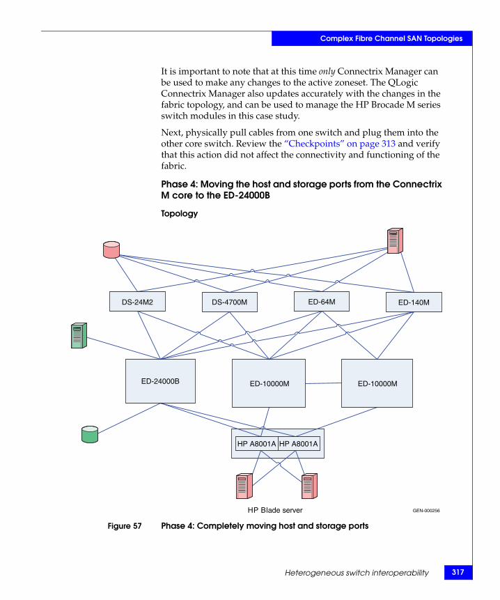
Complex Fibre Channel SAN Topologies
It is important to note that at this time only Connectrix Manager can be used to make any changes to the active zoneset. The QLogic Connectrix Manager also updates accurately with the changes in the fabric topology, and can be used to manage the HP Brocade M series switch modules in this case study.
Next, physically pull cables from one switch and plug them into the other core switch. Review the “Checkpoints” on page 313 and verify that this action did not affect the connectivity and functioning of the fabric.
Phase 4: Moving the host and storage ports from the Connectrix M core to the ED-24000B
Topology
Figure 57 Phase 4: Completely moving host and storage ports
HP Blade server
DS-24M2 DS-4700M ED-64M ED-140M
ED-24000B ED-10000M ED-10000M
HP A8001A HP A8001A
GEN-000256
Heterogeneous switch interoperability 317
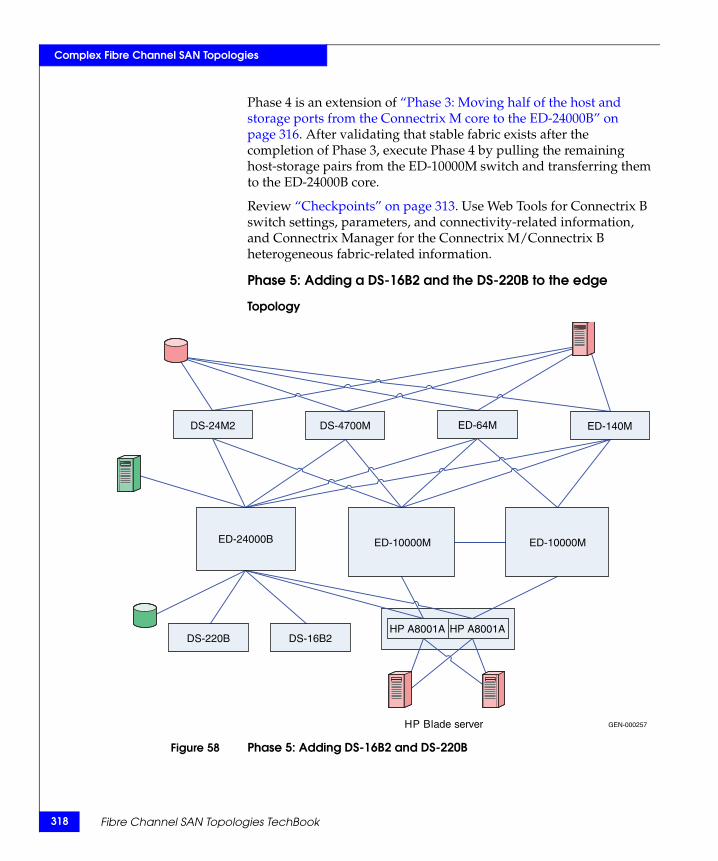
318
Complex Fibre Channel SAN Topologies
Phase 4 is an extension of “Phase 3: Moving half of the host and storage ports from the Connectrix M core to the ED-24000B” on page 316. After validating that stable fabric exists after the completion of Phase 3, execute Phase 4 by pulling the remaining host-storage pairs from the ED-10000M switch and transferring them to the ED-24000B core.
Review “Checkpoints” on page 313. Use Web Tools for Connectrix B switch settings, parameters, and connectivity-related information, and Connectrix Manager for the Connectrix M/Connectrix B heterogeneous fabric-related information.
Phase 5: Adding a DS-16B2 and the DS-220B to the edge
Topology
Figure 58 Phase 5: Adding DS-16B2 and DS-220B
HP Blade server
DS-24M2
DS-220B DS-16B2
DS-4700M ED-64M ED-140M
ED-24000B ED-10000M ED-10000M
HP A8001A HP A8001A
GEN-000257
Fibre Channel SAN Topologies TechBook

Complex Fibre Channel SAN Topologies
Follow these steps to configure the ED-24000B before you add it to the core of the fabric. These steps must be executed on the DS-16B2 and the DS-220B.
1. Telnet into the ED-24000B.
2. Run the interopmode command at the switch command prompt.
3. If interopmode is On, the switch is ready to be a part of a fabric where a Cisco switch will be added. If it is Off, execute Step 4 through Step 8.
4. Disable the switch by running the switchdisable command at the switch prompt.
5. Issue the interopmode 1 command.
6. Enter y to set the interopmode to on. A warning appears. Enter y at this prompt.
7. Reboot the switch to implement new configuration settings.
8. Once the switch is rebooted, repeat Step 1 through Step 3 to verify that the interopmode has been set to On.
If required, after performing the previous procedure, you can link the edge switches with an ISL to both the ED-24000B and ED-10000M core switches.
Follow the “Checkpoints” on page 313 to validate the fabric merge.
Heterogeneous switch interoperability 319
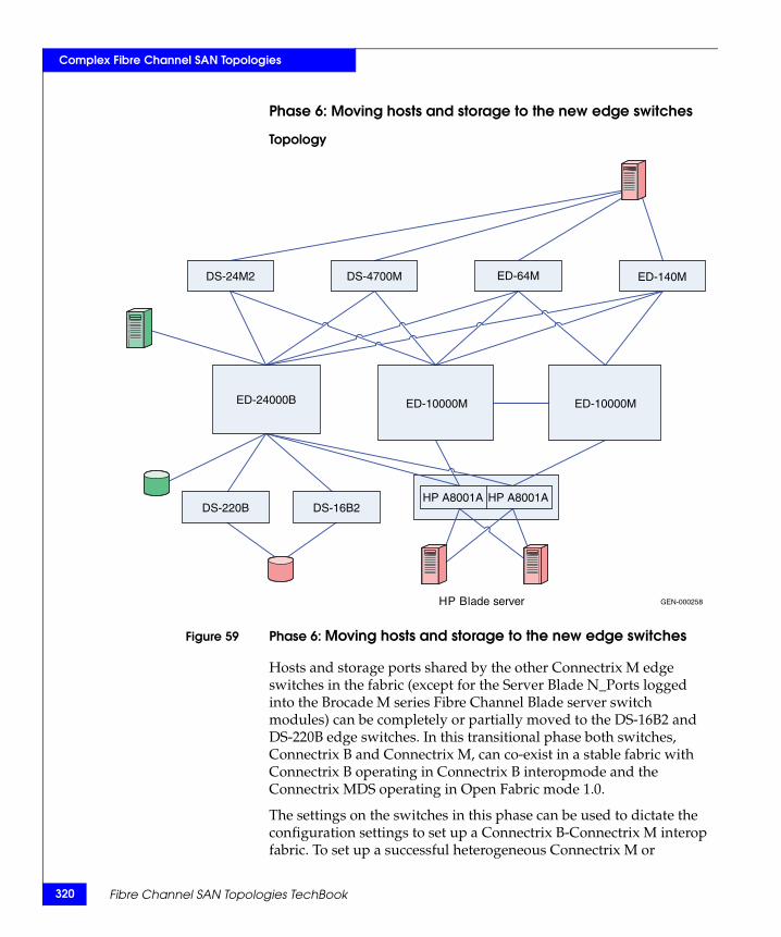
320
Complex Fibre Channel SAN Topologies
Phase 6: Moving hosts and storage to the new edge switches
Topology
Figure 59 Phase 6: Moving hosts and storage to the new edge switches
Hosts and storage ports shared by the other Connectrix M edge switches in the fabric (except for the Server Blade N_Ports logged into the Brocade M series Fibre Channel Blade server switch modules) can be completely or partially moved to the DS-16B2 and DS-220B edge switches. In this transitional phase both switches, Connectrix B and Connectrix M, can co-exist in a stable fabric with Connectrix B operating in Connectrix B interopmode and the Connectrix MDS operating in Open Fabric mode 1.0.
The settings on the switches in this phase can be used to dictate the configuration settings to set up a Connectrix B-Connectrix M interop fabric. To set up a successful heterogeneous Connectrix M or
HP Blade server
DS-24M2
DS-220B DS-16B2
DS-4700M ED-64M ED-140M
ED-24000B ED-10000M ED-10000M
HP A8001A HP A8001A
GEN-000258
Fibre Channel SAN Topologies TechBook
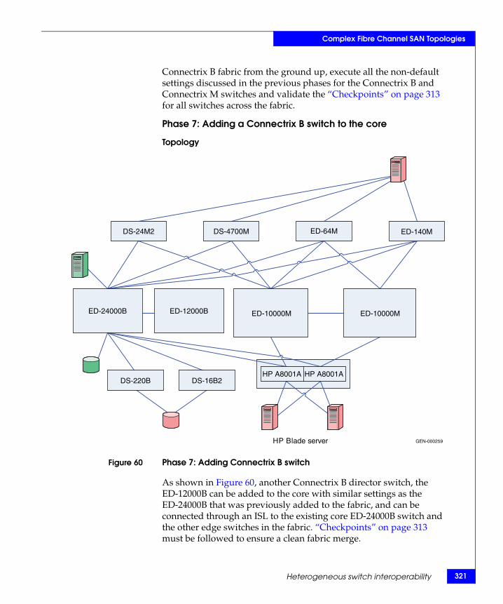
Complex Fibre Channel SAN Topologies
Connectrix B fabric from the ground up, execute all the non-default settings discussed in the previous phases for the Connectrix B and Connectrix M switches and validate the “Checkpoints” on page 313 for all switches across the fabric.
Phase 7: Adding a Connectrix B switch to the core
Topology
Figure 60 Phase 7: Adding Connectrix B switch
As shown in Figure 60, another Connectrix B director switch, the ED-12000B can be added to the core with similar settings as the ED-24000B that was previously added to the fabric, and can be connected through an ISL to the existing core ED-24000B switch and the other edge switches in the fabric. “Checkpoints” on page 313 must be followed to ensure a clean fabric merge.
HP Blade server
DS-24M2
DS-220B DS-16B2
DS-4700M ED-64M ED-140M
ED-24000B ED-12000B ED-10000M ED-10000M
HP A8001A HP A8001A
GEN-000259
Heterogeneous switch interoperability 321
322
Complex Fibre Channel SAN Topologies
Complete migration to Connectrix B
At the end of case study 5, a full migration from a Connectrix M-only fabric to a Connectrix B-Connectrix M fabric with Connectrix Bs at the core, connected through ISLs to every edge switch in the fabric occurred. The host and storage ports (except for the blade server host ports) can be completely moved over to the Connectrix B switches as specified in Phase 3 (refer to “Phase 3: Moving half of the host and storage ports from the Connectrix M core to the ED-24000B” on page 316), Phase 4 (refer to “Phase 4: Moving the host and storage ports from the Connectrix M core to the ED-24000B” on page 317), and Phase 6 (refer to “Phase 6: Moving hosts and storage to the new edge switches” on page 320). The Connectrix M edge switches (except for the blade server Brocade M series switch modules) and the Connectrix M core switches can then be pulled out from the fabric. This results in a fully operational Connectrix B-only fabric. This is a complete migration from one switch type (Connectrix M) to another type (Connectrix B).
IMPORTANT!In a Connectrix B-only fabric, make sure Connectrix B switches operate in their native (interopmode 0) mode. Connectrix B switches are in their interopmode at the end of the migration and it is not possible to make any zoning change to the existing active zoneset on Connectrix B switches since it has been pushed to Connectrix B switches by Connectrix M switches.
In order to change the interopmode on the Connectrix B switches, it is necessary to reboot the switches. As a best practice, it is recommended to reboot the edge switches and then the core switches, depending on how many N_Ports (host and storage) are connected to the edge or core switches, and depending on how rebooting a particular switch affects the I/O running through the fabric.
IMPORTANT!EMC recommends that you schedule some downtime to execute this phase since there will be a state during the transition of the operating modes where some of the switches will segment due to conflicting interopmodes. With the exception of a dual-mirrored core fabric topology, this phase will be disruptive to I/O for all SAN topologies.
Fibre Channel SAN Topologies TechBook
Complex Fibre Channel SAN Topologies
Note: With Brocade/Connectrix B FOS v6.0.x and higher, it is not necessary to reboot the switch after the interopmode has been changed.
After rebooting the switches, the active zoning configuration (effective and defined configuration) on Connectrix Bs is erased, and it is necessary to reconfigure the zoning on Connectrix B switches. It is highly recommended that you back up the configuration and activate it from the Connectrix B switch management application once it is back up (after the reboot) to avoid losing all zoning information previously on the Connectrix B switches.
Note: With Brocade FOS v6.0.x and higher, the CMDCE management application should be used to back up and download the zoning configuration after the interopmodes have been changed.
Warnings or caveats
Refer to EMC Knowledgebase solution emc149735 for all interop issues.
Case study #6: Migrating from a Connectrix M series, McDATA mode to Connectrix B series, Interopmode 0
In response to customer demand for migration solutions, EMC E-Lab and Brocade solution center collaborated on the qualification of the following topology.
This example will walk the user through one possible way of migrating from a Brocade M-EOS fabric running in McDATA Fabric Mode (the donor fabric, also referred to as the source) to a Brocade FOS fabric running in its native mode (the target fabric).
Figure 61 on page 324 shows the donor (source) and target topology. For more details on the donor topology, refer to the “Connectrix M example” on page 163. For more details on the target topology, refer to the “Connectrix B example” on page 194.
Heterogeneous switch interoperability 323
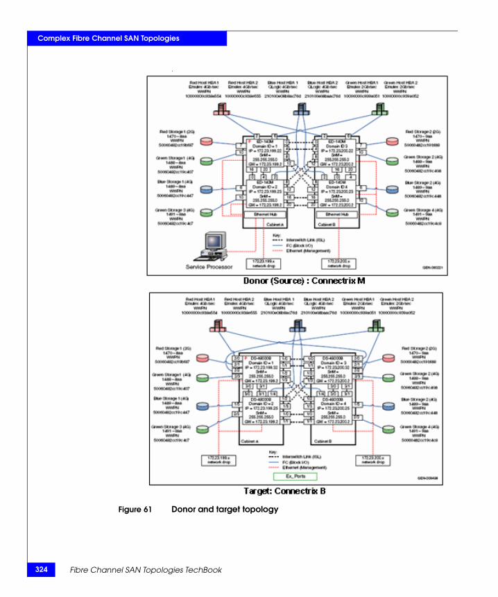
324
Complex Fibre Channel SAN Topologies
.
Figure 61 Donor and target topology
Fibre Channel SAN Topologies TechBook
Complex Fibre Channel SAN Topologies
Note: A Brocade SAN Router is used to support the migration of devices from a Connectrix M fabric running in McDATA Fabric mode (native mode) to a Connectrix B fabric running in Interopmode 0. A Connectrix B SAN Router is available in two form factors:
– As a blade (FR4-18i) installed in a slot of an ED-48000B director,– As a stand alone, 1U pizza box (SAN Router MP-7500B).
Either can be used for migration. The FR4-18i blade is described in this case study. Refer to "Brocade SAN Routing — FCR" in the Networked Storage Concepts and Protocols TechBook, available through the E-Lab Interoperability Navigator, Topology Resource Center tab, at http://elabnavigator.EMC.com, for more details about SAN routers and SAN routing.
Assumptions specific to this case study
◆ Interoperability mode settings on the switches:
• Brocade M series Fabric — The Connectrix M-EOS switches in the fabric are configured to operating in McDATA Fabric mode (M-EOS native mode/McDATA Fabric mode 1.0).
• Brocade B series Fabric — Connectrix B-FOS switches have been configured to operate in Interopmode 0 (FOS native mode).
◆ Fabric Manager applications used for managing the fabric:
• Although this environment can be managed by Connectrix Manager (Brocade EFCM), Brocade Web Tools, or Brocade CLI, the configuration in this case study will be done via Connectrix Manager for the M-EOS products and Brocade CLI for the FOS- based products.:
◆ HA configuration
• Mirrored fabrics for both the Connectrix M and Connectrix B fabrics are supported in configurations similar to this example. However, for simplicity, only one Connectrix M and Connectrix B fabric are shown. The same procedures would be applied to other fabrics to complete the migration.
• Multipath software is installed on all hosts to allow a non-disruptive migration of fabric connections from Connectrix M to Connectrix B fabric.
Heterogeneous switch interoperability 325
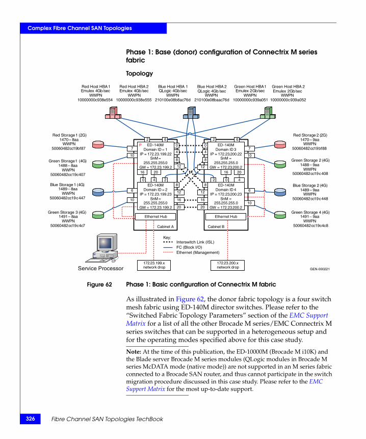
326
Complex Fibre Channel SAN Topologies
Phase 1: Base (donor) configuration of Connectrix M series fabric
Topology
Figure 62 Phase 1: Basic configuration of Connectrix M fabric
As illustrated in Figure 62, the donor fabric topology is a four switch mesh fabric using ED-140M director switches. Please refer to the “Switched Fabric Topology Parameters” section of the EMC Support Matrix for a list of all the other Brocade M series/EMC Connectrix M series switches that can be supported in a heterogeneous setup and for the operating modes specified above for this case study.
Note: At the time of this publication, the ED-10000M (Brocade M i10K) and the Blade server Brocade M series modules (QLogic modules in Brocade M series McDATA mode (native mode)) are not supported in an M series fabric connected to a Brocade SAN router, and thus cannot participate in the switch migration procedure discussed in this case study. Please refer to the EMC Support Matrix for the most up-to-date support.T
GEN-000221
Key:
ED - 140 M Domain ID = 1
IP = 172 . 23 . 199 . 22 SnM =
255 . 255 . 255 . 0 GW = 172 . 23 . 199 . 2
ED - 140 M Domain ID = 2
IP = 172 . 23 . 199 . 23 SnM =
255 . 255 . 255 . 0 GW = 172 . 23 . 199 . 2
ED - 140 M Domain ID 4
IP = 172 . 23 . 200 . 23 SnM =
255 . 255 . 255 . 0 GW = 172 . 23 . 200 . 2
ED - 140 M Domain ID 3
IP = 172 . 23 . 200 . 22 SnM =
255 . 255 . 255 . 0 GW = 172 . 23 . 200 . 2
172 . 23 . 199 . x network drop
Cabinet A Cabinet B
Service Processor
Ethernet Hub Ethernet Hub
172 . 23 . 200 . x network drop
Red Host HBA 1 Emulex 4 Gb / sec
WWPN 10000000 c 938 e 554
Red Host HBA 2 Emulex 4 Gb / sec
WWPN 10000000 c 938 e 555
Green Host HBA 1 Emulex 2 Gb / sec
WWPN 10000000 c 939 a 051
Green Host HBA 2 Emulex 2 Gb / sec
WWPN 10000000 c 939 a 052
Blue Host HBA 1QLogic 4 Gb / sec
WWPN 210100 e 08 b 8 ac 76 d
Blue Host HBA 2 QLogic 4 Gb / sec
WWPN 210100 e 08 baac 76 d
Red Storage 2 ( 2 G ) 1470 – 9 aa
WWPN 50060482 cc 19 bf 88
Red Storage 1 (2G)1470 – 8 aa
WWPN 50060482 cc 19 bf 87
Green Storage 1 ( 4 G ) 1488 – 8 aa
WWPN 50060482 cc 19 c 407
Green Storage 2 ( 4 G ) 1488 – 9 aa
WWPN 50060482 cc 19 c 408
Blue Storage 1 ( 4 G ) 1489 – 8 aa
WWPN 50060482 cc 19 c 447
Blue Storage 2 ( 4 G ) 1489 – 9 aa
WWPN 50060482 cc 19 c 448
Green Storage 3 ( 4 G ) 1491 – 8 aa
WWPN 50060482 cc 19 c 4 c 7
Green Storage 4 ( 4 G ) 1491 – 9 aa
WWPN 50060482 cc 19 c 4 c 8
2 2
0 0
4 4
6 6
0 4 2 2 0 4
16 20
16
20
12
8
8
12
8
12
8
12
16
20
7
10
6
10
16 20
7
10
6
10
Interswitch Link (ISL) FC (Block I/O) Ethernet (Management)
P
Fibre Channel SAN Topologies TechBook
Complex Fibre Channel SAN Topologies
The specific configuration settings, best practices, host and storage layouts, and topology design for this configuration are discussed in the “Connectrix M example” on page 163.
Checkpoints
It is advisable to verify the following fabric characteristics:
◆ Proper distribution of the name server information.
Verify that all the host HBA ports and storage ports logged into the fabric are listed in the name server. This can be accomplished by looking at the node list in the switch's Element Manager from within Connectrix Manager or by using the show nameserver CLI command. Depending on the switch this command was issued on, different information will be displayed.
◆ Proper distribution of zoning information.
Use the Show zoning CLI command or the zoning dialog box in Connectrix Manager to verify that the active zone set comprises zones that contain the desired mapping of host and storage ports.
◆ Proper display of fabric and N_Port elements on the management applications.
Use the show fabric topology CLI command or the topology view in Connectrix Manager to verify that you have the desired physical topology and domain count in the fabric.
◆ No disruption in data transfer.
Verify that the data traffic is running appropriately through the SAN. This can be done in any number of ways. One possibility is to use the EMC inq utility to ensure that the appropriate number of LUNs are visible to the OS. Be sure to save the inq output to a file for future reference. The inq utility is available at ftp://ftp.emc.com/pub/symm3000/inquiry/ (anonymous login).
Before adding the Connectrix B series fabric, it is advisable to verify the following fabric characteristics of the Connectrix M series fabric and to backup critical configuration information using either Connectrix Manager, Connectrix Manager Basic, or the Brocade M series CLI:
◆ Save active zone set.
Verify that a backup copy of the active zone set has been saved for the Connectrix M fabric.
Heterogeneous switch interoperability 327
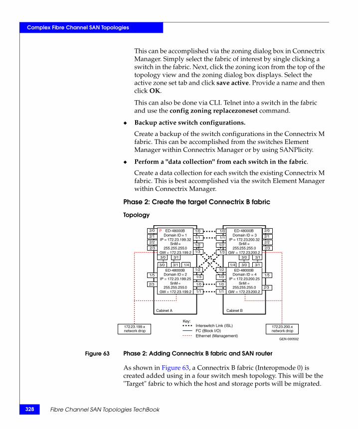
328
Complex Fibre Channel SAN Topologies
This can be accomplished via the zoning dialog box in Connectrix Manager. Simply select the fabric of interest by single clicking a switch in the fabric. Next, click the zoning icon from the top of the topology view and the zoning dialog box displays. Select the active zone set tab and click save active. Provide a name and then click OK.
This can also be done via CLI. Telnet into a switch in the fabric and use the config zoning replacezoneset command.
◆ Backup active switch configurations.
Create a backup of the switch configurations in the Connectrix M fabric. This can be accomplished from the switches Element Manager within Connectrix Manager or by using SANPlicity.
◆ Perform a "data collection" from each switch in the fabric.
Create a data collection for each switch the existing Connectrix M fabric. This is best accomplished via the switch Element Manager within Connectrix Manager.
Phase 2: Create the target Connectrix B fabric
Topology
Figure 63 Phase 2: Adding Connectrix B fabric and SAN router
As shown in Figure 63, a Connectrix B fabric (Interopmode 0) is created added using in a four switch mesh topology. This will be the "Target" fabric to which the host and storage ports will be migrated.
GEN-000502
Key:
Domain ID = 1 IP = 172 . 23 . 199 . 32
SnM = 255 . 255 . 255 . 0
GW = 172 . 23 . 199 . 2
Domain ID = 2 IP = 172 . 23 . 199 . 25
SnM = 255 . 255 . 255 . 0
GW = 172 . 23 . 199 . 2
Domain ID = 4IP = 172 . 23 . 200 . 25
SnM = 255 . 255 . 255 . 0
GW = 172 . 23 . 200 . 2
Domain ID = 3IP = 172 . 23 . 200 . 32
SnM = 255 . 255 . 255 . 0
GW = 172 . 23 . 200 . 2
172.23.199.x network drop
Cabinet A Cabinet B
172.23.200.x network drop
1/0 1/0
1/1 1/1
3/0 3/1 1/4 1/4 3/0 3/1
3/0 3/1
1/0
1/1
1/3
1/2
1/2
1/3
1/2
1/3
1/2
1/3
1/0
1/1
2/2
2/1
2/0
2/3
2/2
2/1
2/0
2/3
1/5
2/3
3/0 3/1
1/5
2/3
Interswitch Link (ISL) FC (Block I/O) Ethernet (Management)
P ED-48000B
ED-48000B
ED-48000B
ED-48000B
Fibre Channel SAN Topologies TechBook

Complex Fibre Channel SAN Topologies
For simplification, the target topology shown matches the base donor fabrics topology used for the Connectrix M fabric, but in practice, the target topology can be any suitable topology supported for Connectrix B series fabrics.
The specific configuration settings, best practices, host and storage layouts, and topology design for this configuration are discussed in the “Connectrix B example” on page 194.
Heterogeneous switch interoperability 329
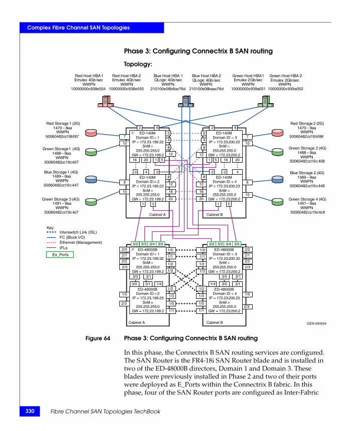
330
Complex Fibre Channel SAN Topologies
Phase 3: Configuring Connectrix B SAN routing
Topology:
Figure 64 Phase 3: Configuring Connectrix B SAN routing
In this phase, the Connectrix B SAN routing services are configured. The SAN Router is the FR4-18i SAN Router blade and is installed in two of the ED-48000B directors, Domain 1 and Domain 3. These blades were previously installed in Phase 2 and two of their ports were deployed as E_Ports within the Connectrix B fabric. In this phase, four of the SAN Router ports are configured as Inter-Fabric
GEN-000504
Domain ID = 1 IP = 172 . 23 . 199 . 22
SnM = 255 . 255 . 255 . 0
GW = 172 . 23 . 199 . 2
Domain ID = 2IP = 172.23.199.23
SnM = 255.255.255.0
GW = 172.23.199.2
Domain ID = 4IP = 172.23.200.23
SnM = 255.255.255.0
GW = 172.23.200.2
Domain ID = 3IP = 172.23.200.22
SnM = 255.255.255.0
GW = 172.23.200.2
Cabinet A Cabinet B
Red Host HBA 1 Emulex 4 Gb / sec
WWPN 10000000 c 938 e 554
Red Host HBA 2 Emulex 4 Gb / sec
WWPN 10000000 c 938 e 555
Green Host HBA 1Emulex 2 Gb/sec
WWPN10000000c939a051
Green Host HBA 2Emulex 2 Gb/sec
WWPN10000000c939a052
Blue Host HBA 1QLogic 4Gb/sec
WWPN210100e08b8ac76d
Blue Host HBA 2QLogic 4Gb /sec
WWPN210100e08baac76d
Red Storage 2 (2G)1470 – 9aa
WWPN50060482cc19bf88
Red Storage 1 (2G)1470 – 8 aa
WWPN 50060482 cc 19 bf 87
Green Storage 1 ( 4 G ) 1488 – 8 aa
WWPN 50060482 cc 19 c 407
Green Storage 2 (4G)1488 – 9aa
WWPN50060482cc19c408
Blue Storage 1 ( 4 G ) 1489 – 8 aa
WWPN 50060482 cc 19 c 447
Blue Storage 2 (4G)1489 – 9aa
WWPN50060482cc19c448
Green Storage 3 ( 4 G ) 1491 – 8 aa
WWPN 50060482 cc 19 c 4 c 7
Green Storage 4 (4G)1491 – 9aa
WWPN50060482cc19c4c8
2
1 5
1 5 1 5
1 5
2
0 0
4 4
6 6
0 4 2 2 0 4
16 20
16
20
12
8
8
12
8
12
8
12
16
20
7
10
6
10
16 20
7
10
6
10
P
Domain ID = 1IP = 172.23.199.32
SnM = 255.255.255.0
GW = 172.23.199.2
Domain ID = 2IP = 172.23.199.25
SnM = 255.255.255.0
GW = 172.23.199.2
Domain ID = 4IP = 172.23.200.25
SnM = 255.255.255.0
GW = 172.23.200.2
Domain ID = 3IP = 172.23.200.32
SnM = 255.255.255.0
GW = 172.23.200.2
Cabinet A Cabinet B
1/0
3/53/43/33/2 3/53/43/33/2
1/0
1/1 1/1
3/0 3/1 1/4 1/4 3/0 3/1
3/0 3/1
1/0
1/1
1/3
1/2
1/2
1/3
1/2
1/3
1/2
1/3
1/0
1/1
2/2
2/1
2/0
2/3
2/2
2/1
2/0
2/3
1/5
2/3
3/0 3/1
1/5
2/3
Key:Interswitch Link (ISL)FC (Block I/O)Ethernet (Management)
PEx_Ports
IFLs
ED-140M
ED-140M
ED-140M
ED-140M
ED-48000B
ED-48000B
ED-48000B
ED-48000B
Fibre Channel SAN Topologies TechBook
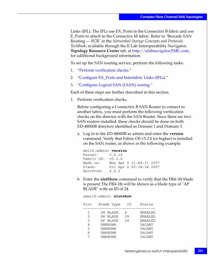
Complex Fibre Channel SAN Topologies
Links (IFL). The IFLs use EX_Ports in the Connectrix B fabric and use E_Ports to attach to the Connectrix M fabric. Refer to "Brocade SAN Routing — FCR" in the Networked Storage Concepts and Protocols TechBook, available through the E-Lab Interoperability Navigator, Topology Resource Center tab, at http://elabnavigator.EMC.com, for additional background information.
To set up the SAN routing service, perform the following tasks:
1. “Perform verification checks.”
2. “Configure EX_Ports and Interfabric Links (IFLs).”
3. “Configure Logical SAN (LSAN) zoning.”
Each of these steps are further described in this section.
1. Perform verification checks.
Before configuring a Connectrix B SAN Router to connect to another fabric, you must perform the following verification checks on the director with the SAN Router. Since there are two SAN routers installed, these checks should be done on both ED-48000B directors identified as Domain 1 and Domain 3.
a. Log in to the ED-48000B as admin and enter the version command. Verify that Fabric OS v5.3.0 (or higher) is installed on the SAN router, as shown in the following example.
mw116:admin> versionKernel: 2.6.14Fabric OS: v5.3.0Made on: Mon Apr 2 21:44:31 2007Flash: Fri Apr 6 00:34:34 2007BootProm: 4.6.2
b. Enter the slotShow command to verify that the FR4-18i blade is present The FR4-18i will be shown as a blade type of "AP BLADE" with an ID of 24.
smw116:admin> slotshow
Slot Blade Type ID Status--------------------------------- 1 SW BLADE 4 ENABLED 2 SW BLADE 39 ENABLED 3 AP BLADE 24 ENABLED 4 UNKNOWN VACANT 5 UNKNOWN VACANT 6 UNKNOWN VACANT 7 UNKNOWN VACANT
Heterogeneous switch interoperability 331
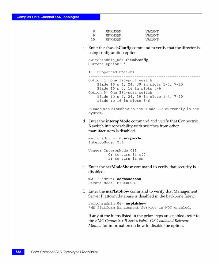
332
Complex Fibre Channel SAN Topologies
8 UNKNOWN VACANT 9 UNKNOWN VACANT 10 UNKNOWN VACANT
c. Enter the chassisConfig command to verify that the director is using configuration option
switch:admin_06> chassisconfigCurrent Option: 5
All Supported Options---------------------------------------------------Option 1: One 128-port switch Blade ID's 4, 24, 39 in slots 1-4, 7-10 Blade ID's 5, 16 in slots 5-6Option 5: One 384-port switch Blade ID's 4, 24, 39 in slots 1-4, 7-10 Blade ID 16 in slots 5-6
Please use slotshow to see Blade IDs currently in the system.
d. Enter the interopMode command and verify that Connectrix B switch interoperability with switches from other manufacturers is disabled.
mw116:admin> interopmodeInteropMode: Off
Usage: InteropMode 0|1 0: to turn it off 1: to turn it on
e. Enter the secModeShow command to verify that security is disabled.
mw116:admin> secmodeshowSecure Mode: DISABLED.
f. Enter the msPlatShow command to verify that Management Server Platform database is disabled in the backbone fabric.
switch:admin_06> msplatshow*MS Platform Management Service is NOT enabled.
If any of the items listed in the prior steps are enabled, refer to the EMC Connectrix B Series Fabric OS Command Reference Manual for information on how to disable the option.
Fibre Channel SAN Topologies TechBook
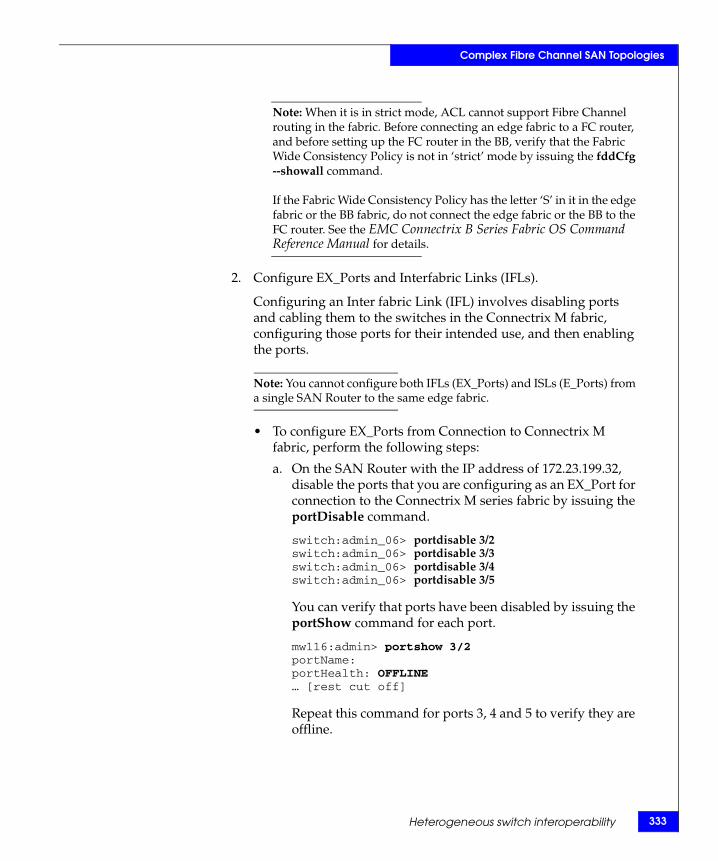
Complex Fibre Channel SAN Topologies
Note: When it is in strict mode, ACL cannot support Fibre Channel routing in the fabric. Before connecting an edge fabric to a FC router, and before setting up the FC router in the BB, verify that the Fabric Wide Consistency Policy is not in ‘strict’ mode by issuing the fddCfg --showall command.
If the Fabric Wide Consistency Policy has the letter ‘S’ in it in the edge fabric or the BB fabric, do not connect the edge fabric or the BB to the FC router. See the EMC Connectrix B Series Fabric OS Command Reference Manual for details.
2. Configure EX_Ports and Interfabric Links (IFLs).
Configuring an Inter fabric Link (IFL) involves disabling ports and cabling them to the switches in the Connectrix M fabric, configuring those ports for their intended use, and then enabling the ports.
Note: You cannot configure both IFLs (EX_Ports) and ISLs (E_Ports) from a single SAN Router to the same edge fabric.
• To configure EX_Ports from Connection to Connectrix M fabric, perform the following steps:
a. On the SAN Router with the IP address of 172.23.199.32, disable the ports that you are configuring as an EX_Port for connection to the Connectrix M series fabric by issuing the portDisable command.
switch:admin_06> portdisable 3/2switch:admin_06> portdisable 3/3switch:admin_06> portdisable 3/4switch:admin_06> portdisable 3/5
You can verify that ports have been disabled by issuing the portShow command for each port.
mw116:admin> portshow 3/2portName:portHealth: OFFLINE… [rest cut off]
Repeat this command for ports 3, 4 and 5 to verify they are offline.
Heterogeneous switch interoperability 333
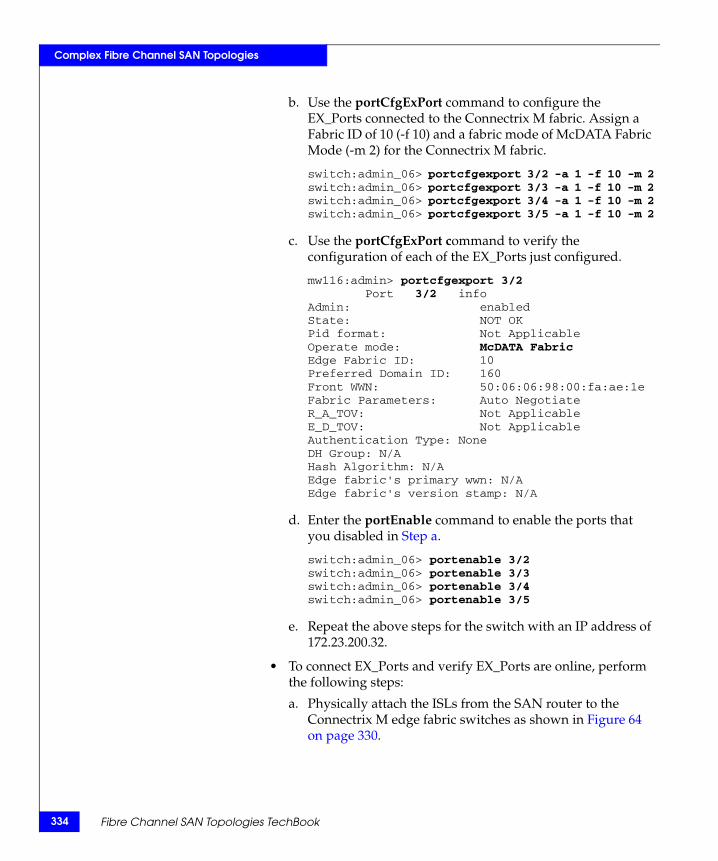
334
Complex Fibre Channel SAN Topologies
b. Use the portCfgExPort command to configure the EX_Ports connected to the Connectrix M fabric. Assign a Fabric ID of 10 (-f 10) and a fabric mode of McDATA Fabric Mode (-m 2) for the Connectrix M fabric.
switch:admin_06> portcfgexport 3/2 -a 1 -f 10 -m 2switch:admin_06> portcfgexport 3/3 -a 1 -f 10 -m 2switch:admin_06> portcfgexport 3/4 -a 1 -f 10 -m 2switch:admin_06> portcfgexport 3/5 -a 1 -f 10 -m 2
c. Use the portCfgExPort command to verify the configuration of each of the EX_Ports just configured.
mw116:admin> portcfgexport 3/2 Port 3/2 infoAdmin: enabledState: NOT OKPid format: Not ApplicableOperate mode: McDATA FabricEdge Fabric ID: 10Preferred Domain ID: 160Front WWN: 50:06:06:98:00:fa:ae:1eFabric Parameters: Auto NegotiateR_A_TOV: Not ApplicableE_D_TOV: Not ApplicableAuthentication Type: NoneDH Group: N/AHash Algorithm: N/AEdge fabric's primary wwn: N/AEdge fabric's version stamp: N/A
d. Enter the portEnable command to enable the ports that you disabled in Step a.
switch:admin_06> portenable 3/2switch:admin_06> portenable 3/3switch:admin_06> portenable 3/4switch:admin_06> portenable 3/5
e. Repeat the above steps for the switch with an IP address of 172.23.200.32.
• To connect EX_Ports and verify EX_Ports are online, perform the following steps:
a. Physically attach the ISLs from the SAN router to the Connectrix M edge fabric switches as shown in Figure 64 on page 330.
Fibre Channel SAN Topologies TechBook
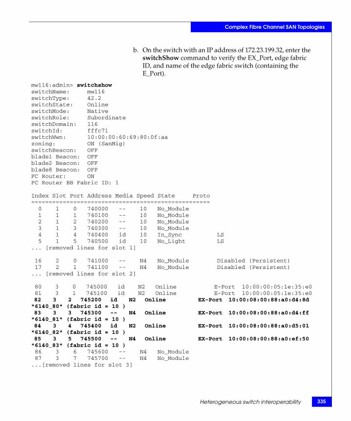
Complex Fibre Channel SAN Topologies
b. On the switch with an IP address of 172.23.199.32, enter the switchShow command to verify the EX_Port, edge fabric ID, and name of the edge fabric switch (containing the E_Port).
mw116:admin> switchshowswitchName: mw116switchType: 42.2switchState: OnlineswitchMode: NativeswitchRole: SubordinateswitchDomain: 116switchId: fffc71switchWwn: 10:00:00:60:69:80:0f:aazoning: ON (SanMig)switchBeacon: OFFblade1 Beacon: OFFblade2 Beacon: OFFblade8 Beacon: OFFFC Router: ONFC Router BB Fabric ID: 1
Index Slot Port Address Media Speed State Proto=================================================== 0 1 0 740000 -- 10 No_Module 1 1 1 740100 -- 10 No_Module 2 1 2 740200 -- 10 No_Module 3 1 3 740300 -- 10 No_Module 4 1 4 740400 id 10 In_Sync LS 5 1 5 740500 id 10 No_Light LS... [removed lines for slot 1]
16 2 0 741000 -- N4 No_Module Disabled (Persistent) 17 2 1 741100 -- N4 No_Module Disabled (Persistent)... [removed lines for slot 2]
80 3 0 745000 id N2 Online E-Port 10:00:00:05:1e:35:e0 81 3 1 745100 id N2 Online E-Port 10:00:00:05:1e:35:e0 82 3 2 745200 id N2 Online EX-Port 10:00:08:00:88:a0:d4:8d "6140_80" (fabric id = 10 ) 83 3 3 745300 -- N4 Online EX-Port 10:00:08:00:88:a0:d4:ff "6140_81" (fabric id = 10 ) 84 3 4 745400 id N2 Online EX-Port 10:00:08:00:88:a0:d5:01 "6140_82" (fabric id = 10 ) 85 3 5 745500 -- N4 Online EX-Port 10:00:08:00:88:a0:ef:50 "6140_83" (fabric id = 10 ) 86 3 6 745600 -- N4 No_Module 87 3 7 745700 -- N4 No_Module...[removed lines for slot 3]
Heterogeneous switch interoperability 335
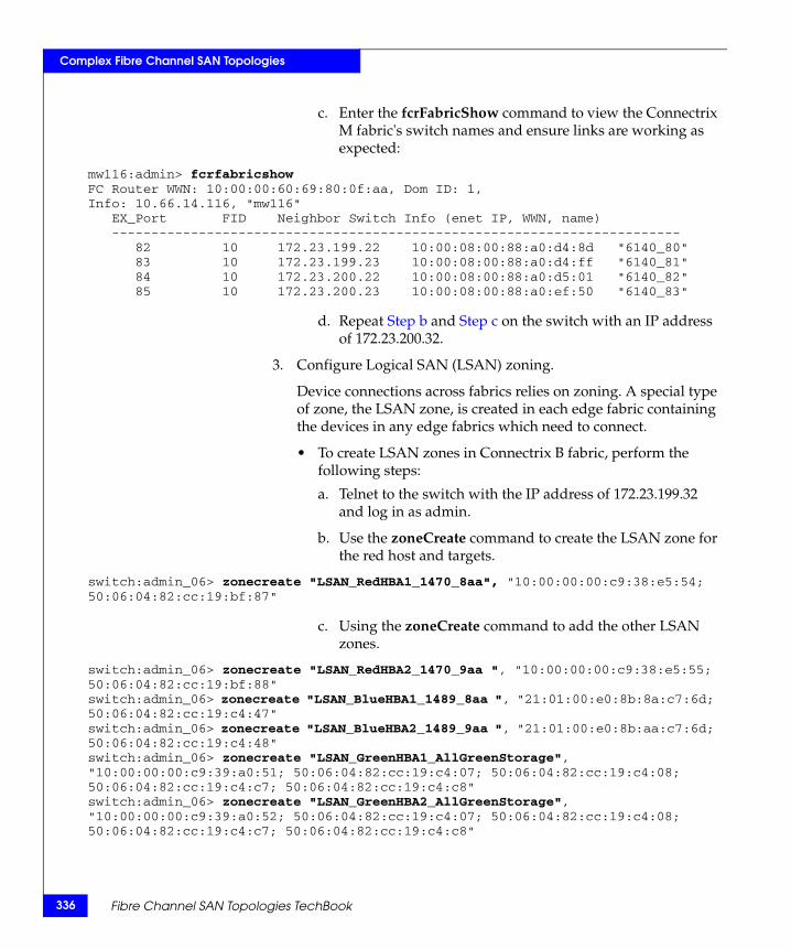
336
Complex Fibre Channel SAN Topologies
c. Enter the fcrFabricShow command to view the Connectrix M fabric's switch names and ensure links are working as expected:
mw116:admin> fcrfabricshowFC Router WWN: 10:00:00:60:69:80:0f:aa, Dom ID: 1,Info: 10.66.14.116, "mw116" EX_Port FID Neighbor Switch Info (enet IP, WWN, name) ------------------------------------------------------------------------ 82 10 172.23.199.22 10:00:08:00:88:a0:d4:8d "6140_80" 83 10 172.23.199.23 10:00:08:00:88:a0:d4:ff "6140_81" 84 10 172.23.200.22 10:00:08:00:88:a0:d5:01 "6140_82" 85 10 172.23.200.23 10:00:08:00:88:a0:ef:50 "6140_83"
d. Repeat Step b and Step c on the switch with an IP address of 172.23.200.32.
3. Configure Logical SAN (LSAN) zoning.
Device connections across fabrics relies on zoning. A special type of zone, the LSAN zone, is created in each edge fabric containing the devices in any edge fabrics which need to connect.
• To create LSAN zones in Connectrix B fabric, perform the following steps:
a. Telnet to the switch with the IP address of 172.23.199.32 and log in as admin.
b. Use the zoneCreate command to create the LSAN zone for the red host and targets.
switch:admin_06> zonecreate "LSAN_RedHBA1_1470_8aa", "10:00:00:00:c9:38:e5:54; 50:06:04:82:cc:19:bf:87"
c. Using the zoneCreate command to add the other LSAN zones.
switch:admin_06> zonecreate "LSAN_RedHBA2_1470_9aa ", "10:00:00:00:c9:38:e5:55; 50:06:04:82:cc:19:bf:88"switch:admin_06> zonecreate "LSAN_BlueHBA1_1489_8aa ", "21:01:00:e0:8b:8a:c7:6d; 50:06:04:82:cc:19:c4:47"switch:admin_06> zonecreate "LSAN_BlueHBA2_1489_9aa ", "21:01:00:e0:8b:aa:c7:6d; 50:06:04:82:cc:19:c4:48"switch:admin_06> zonecreate "LSAN_GreenHBA1_AllGreenStorage", "10:00:00:00:c9:39:a0:51; 50:06:04:82:cc:19:c4:07; 50:06:04:82:cc:19:c4:08; 50:06:04:82:cc:19:c4:c7; 50:06:04:82:cc:19:c4:c8"switch:admin_06> zonecreate "LSAN_GreenHBA2_AllGreenStorage", "10:00:00:00:c9:39:a0:52; 50:06:04:82:cc:19:c4:07; 50:06:04:82:cc:19:c4:08; 50:06:04:82:cc:19:c4:c7; 50:06:04:82:cc:19:c4:c8"
Fibre Channel SAN Topologies TechBook
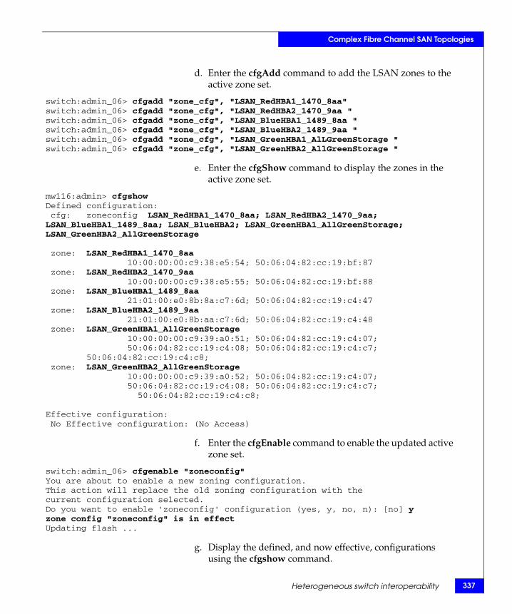
Complex Fibre Channel SAN Topologies
d. Enter the cfgAdd command to add the LSAN zones to the active zone set.
switch:admin_06> cfgadd "zone_cfg", "LSAN_RedHBA1_1470_8aa"switch:admin_06> cfgadd "zone_cfg", "LSAN_RedHBA2_1470_9aa "switch:admin_06> cfgadd "zone_cfg", "LSAN_BlueHBA1_1489_8aa "switch:admin_06> cfgadd "zone_cfg", "LSAN_BlueHBA2_1489_9aa "switch:admin_06> cfgadd "zone_cfg", "LSAN_GreenHBA1_AlLGreenStorage "switch:admin_06> cfgadd "zone_cfg", "LSAN_GreenHBA2_AllGreenStorage "
e. Enter the cfgShow command to display the zones in the active zone set.
mw116:admin> cfgshowDefined configuration: cfg: zoneconfig LSAN_RedHBA1_1470_8aa; LSAN_RedHBA2_1470_9aa; LSAN_BlueHBA1_1489_8aa; LSAN_BlueHBA2; LSAN_GreenHBA1_AllGreenStorage; LSAN_GreenHBA2_AllGreenStorage
zone: LSAN_RedHBA1_1470_8aa 10:00:00:00:c9:38:e5:54; 50:06:04:82:cc:19:bf:87 zone: LSAN_RedHBA2_1470_9aa 10:00:00:00:c9:38:e5:55; 50:06:04:82:cc:19:bf:88 zone: LSAN_BlueHBA1_1489_8aa 21:01:00:e0:8b:8a:c7:6d; 50:06:04:82:cc:19:c4:47 zone: LSAN_BlueHBA2_1489_9aa 21:01:00:e0:8b:aa:c7:6d; 50:06:04:82:cc:19:c4:48 zone: LSAN_GreenHBA1_AllGreenStorage 10:00:00:00:c9:39:a0:51; 50:06:04:82:cc:19:c4:07; 50:06:04:82:cc:19:c4:08; 50:06:04:82:cc:19:c4:c7;
50:06:04:82:cc:19:c4:c8; zone: LSAN_GreenHBA2_AllGreenStorage 10:00:00:00:c9:39:a0:52; 50:06:04:82:cc:19:c4:07; 50:06:04:82:cc:19:c4:08; 50:06:04:82:cc:19:c4:c7;
50:06:04:82:cc:19:c4:c8;
Effective configuration: No Effective configuration: (No Access)
f. Enter the cfgEnable command to enable the updated active zone set.
switch:admin_06> cfgenable "zoneconfig"You are about to enable a new zoning configuration.This action will replace the old zoning configuration with thecurrent configuration selected.Do you want to enable 'zoneconfig' configuration (yes, y, no, n): [no] yzone config "zoneconfig" is in effectUpdating flash ...
g. Display the defined, and now effective, configurations using the cfgshow command.
Heterogeneous switch interoperability 337
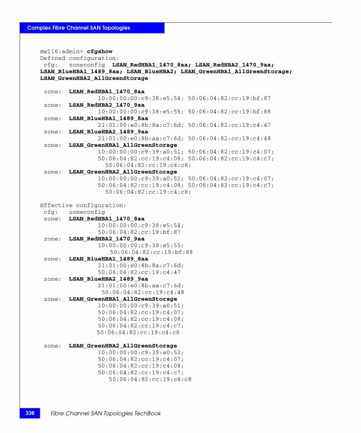
338
Complex Fibre Channel SAN Topologies
mw116:admin> cfgshowDefined configuration: cfg: zoneconfig LSAN_RedHBA1_1470_8aa; LSAN_RedHBA2_1470_9aa; LSAN_BlueHBA1_1489_8aa; LSAN_BlueHBA2; LSAN_GreenHBA1_AllGreenStorage; LSAN_GreenHBA2_AllGreenStorage
zone: LSAN_RedHBA1_1470_8aa 10:00:00:00:c9:38:e5:54; 50:06:04:82:cc:19:bf:87 zone: LSAN_RedHBA2_1470_9aa 10:00:00:00:c9:38:e5:55; 50:06:04:82:cc:19:bf:88 zone: LSAN_BlueHBA1_1489_8aa 21:01:00:e0:8b:8a:c7:6d; 50:06:04:82:cc:19:c4:47 zone: LSAN_BlueHBA2_1489_9aa 21:01:00:e0:8b:aa:c7:6d; 50:06:04:82:cc:19:c4:48 zone: LSAN_GreenHBA1_AllGreenStorage 10:00:00:00:c9:39:a0:51; 50:06:04:82:cc:19:c4:07; 50:06:04:82:cc:19:c4:08; 50:06:04:82:cc:19:c4:c7;
50:06:04:82:cc:19:c4:c8; zone: LSAN_GreenHBA2_AllGreenStorage 10:00:00:00:c9:39:a0:52; 50:06:04:82:cc:19:c4:07; 50:06:04:82:cc:19:c4:08; 50:06:04:82:cc:19:c4:c7;
50:06:04:82:cc:19:c4:c8;
Effective configuration: cfg: zoneconfig zone: LSAN_RedHBA1_1470_8aa 10:00:00:00:c9:38:e5:54; 50:06:04:82:cc:19:bf:87 zone: LSAN_RedHBA2_1470_9aa 10:00:00:00:c9:38:e5:55;
50:06:04:82:cc:19:bf:88 zone: LSAN_BlueHBA1_1489_8aa 21:01:00:e0:8b:8a:c7:6d; 50:06:04:82:cc:19:c4:47 zone: LSAN_BlueHBA2_1489_9aa 21:01:00:e0:8b:aa:c7:6d; 50:06:04:82:cc:19:c4:48 zone: LSAN_GreenHBA1_AllGreenStorage 10:00:00:00:c9:39:a0:51; 50:06:04:82:cc:19:c4:07; 50:06:04:82:cc:19:c4:08; 50:06:04:82:cc:19:c4:c7;
50:06:04:82:cc:19:c4:c8
zone: LSAN_GreenHBA2_AllGreenStorage 10:00:00:00:c9:39:a0:52; 50:06:04:82:cc:19:c4:07; 50:06:04:82:cc:19:c4:08; 50:06:04:82:cc:19:c4:c7;
50:06:04:82:cc:19:c4:c8
Fibre Channel SAN Topologies TechBook

Complex Fibre Channel SAN Topologies
h. Enter the cfgSave command to save the updated active zone set.
• To create LSAN zones in Connectrix M fabric, perform the following steps:
Although the only requirement to create an LSAN between the Connectrix M and Connectrix B fabric is that the LSAN zones need to have the same devices zoned together and the zone names of the LSAN zones must start with the string "LSAN_", it is still a best practice to create identical zones with identical zone names in order to maximize ease of use.
a. Open the Zoning dialog box in Connectrix Manager by right- clicking the appropriate fabric topology and selecting the zoning menu item.
b. Create a zone by clicking on the New Zone button under the Zones "Tree".
c. Provide a descriptive name for the zone. In this case, we are going to zone "Red host HBA 1" and "Red Storage 1". We will enter "LSAN_RedHBA1_1470_8aa" and press Enter.
d. Locate and then single-click on "Red Host HBA 1" (WWPN 10000000c938e554) in the Potential Zone Members list.
e. Click the right-pointing arrow on the divider between the Potential Members list and the Zones list to add the HBA to the zone.
f. Locate and then single-click on "Red Storage 1" (WWPN 50060482cc19bf87) in the Potential Zone Members list.
g. Click the right-pointing arrow on the divider between the Potential Members list and the Zones list to add the storage port to the zone.
h. Repeat Step b through Step g for all host and storage pairs in the environment.
i. Select the active zone set (for example, Oct_31_06_1140) in the Zone Set panel. Select one of the LSAN zones you just created in the Zone panel, and click the right-pointing arrow on the divider to add the zones to this zone set.
Heterogeneous switch interoperability 339
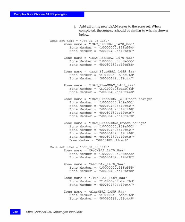
340
Complex Fibre Channel SAN Topologies
j. Add all of the new LSAN zones to the zone set. When completed, the zone set should be similar to what is shown below.
Zone set name = "Oct_31_06_1140"Zone name = "LSAN_RedHBA1_1470_8aa"
Zone Member = "10000000c938e554"Zone Member = "50060482cc19bf87"
Zone name = "LSAN_RedHBA2_1470_9aa"Zone Member = "10000000c938e555"Zone Member = "50060482cc19bf88"
Zone name = "LSAN_BlueHBA1_1489_8aa"Zone Member = "210100e08b8ac76d"Zone Member = "50060482cc19c447"
Zone name = "LSAN_BlueHBA2_1489_9aa"Zone Member = "210100e08baac76d"Zone Member = "50060482cc19c448"
Zone name = "LSAN_GreenHBA1_AllGreenStorage"Zone Member = "10000000c939a051"Zone Member = "50060482cc19c407"Zone Member = "50060482cc19c408"Zone Member = "50060482cc19c4c7"Zone Member = "50060482cc19c4c8"
Zone name = "LSAN_GreenHBA2_GreenStorage"Zone Member = "10000000c939a052"Zone Member = "50060482cc19c407"Zone Member = "50060482cc19c408"Zone Member = "50060482cc19c4c7"Zone Member = "50060482cc19c4c8"
Zone set name = "Oct_31_06_1140"Zone name = "RedHBA1_1470_8aa"
Zone Member = "10000000c938e554"Zone Member = "50060482cc19bf87"
Zone name = "RedHBA2_1470_9aa"Zone Member = "10000000c938e555"Zone Member = "50060482cc19bf88"
Zone name = "BlueHBA1_1489_8aa"Zone Member = "210100e08b8ac76d"Zone Member = "50060482cc19c447"
Zone name = "BlueHBA2_1489_9aa"Zone Member = "210100e08baac76d"Zone Member = "50060482cc19c448"
Fibre Channel SAN Topologies TechBook
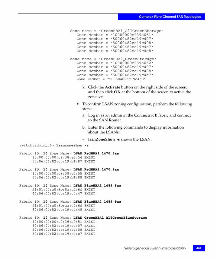
Complex Fibre Channel SAN Topologies
Zone name = "GreenHBA1_AllGreenStorage"Zone Member = "10000000c939a051"Zone Member = "50060482cc19c407"Zone Member = "50060482cc19c408"Zone Member = "50060482cc19c4c7"Zone Member = "50060482cc19c4c8"
Zone name = "GreenHBA2_GreenStorage"Zone Member = "10000000c939a052"Zone Member = "50060482cc19c407"Zone Member = "50060482cc19c408"Zone Member = "50060482cc19c4c7"Zone Member = "50060482cc19c4c8"
k. Click the Activate button on the right side of the screen, and then click OK at the bottom of the screen to active the zone set.
• To confirm LSAN zoning configuration, perform the following steps:
a. Log in as an admin in the Connectrix B fabric and connect to the SAN Router.
b. Enter the following commands to display information about the LSANs:
– lsanZoneShow -s shows the LSAN.switch:admin_06> lsanzoneshow -s
Fabric ID: 10 Zone Name: LSAN_RedHBA1_1470_8aa10:00:00:00:c9:38:e5:54 EXIST50:06:04:82:cc:19:bf:87 EXIST
Fabric ID: 10 Zone Name: LSAN_RedHBA2_1470_9aa10:00:00:00:c9:38:e5:55 EXIST50:06:04:82:cc:19:bf:88 EXIST
Fabric ID: 10 Zone Name: LSAN_BlueHBA1_1489_8aa21:01:00:e0:8b:8a:c7:6d EXIST50:06:04:82:cc:19:c4:47 EXIST
Fabric ID: 10 Zone Name: LSAN_BlueHBA2_1489_9aa21:01:00:e0:8b:aa:c7:6d EXIST50:06:04:82:cc:19:c4:48 EXIST
Fabric ID: 10 Zone Name: LSAN_GreenHBA1_AllGreenBlueStorage10:00:00:00:c9:39:a0:51 EXIST50:06:04:82:cc:19:c4:07 EXIST50:06:04:82:cc:19:c4:08 EXIST50:06:04:82:cc:19:c4:c7 EXIST
Heterogeneous switch interoperability 341
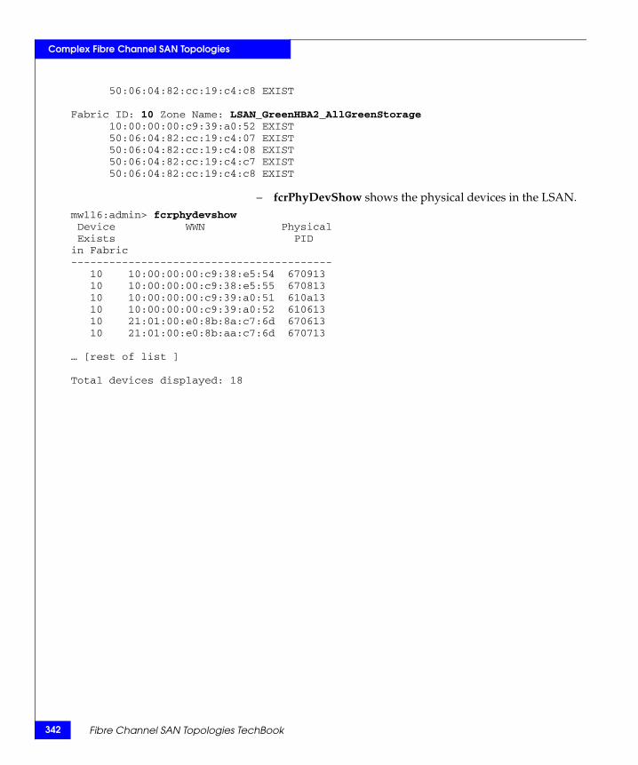
342
Complex Fibre Channel SAN Topologies
50:06:04:82:cc:19:c4:c8 EXIST
Fabric ID: 10 Zone Name: LSAN_GreenHBA2_AllGreenStorage10:00:00:00:c9:39:a0:52 EXIST50:06:04:82:cc:19:c4:07 EXIST50:06:04:82:cc:19:c4:08 EXIST50:06:04:82:cc:19:c4:c7 EXIST50:06:04:82:cc:19:c4:c8 EXIST
– fcrPhyDevShow shows the physical devices in the LSAN.mw116:admin> fcrphydevshow Device WWN Physical Exists PIDin Fabric----------------------------------------- 10 10:00:00:00:c9:38:e5:54 670913 10 10:00:00:00:c9:38:e5:55 670813 10 10:00:00:00:c9:39:a0:51 610a13 10 10:00:00:00:c9:39:a0:52 610613 10 21:01:00:e0:8b:8a:c7:6d 670613 10 21:01:00:e0:8b:aa:c7:6d 670713
… [rest of list ]
Total devices displayed: 18
Fibre Channel SAN Topologies TechBook
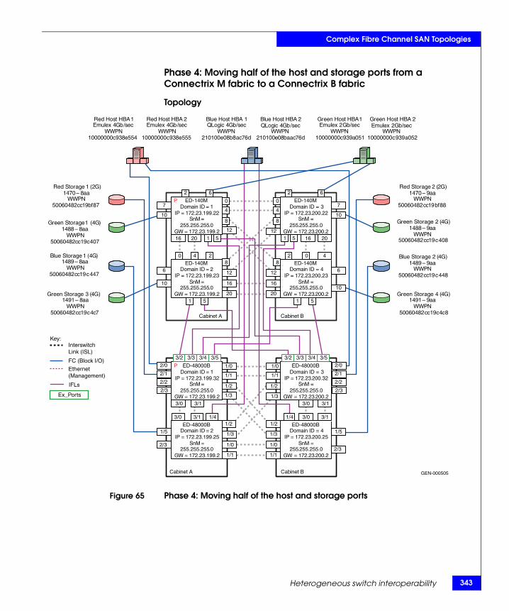
Complex Fibre Channel SAN Topologies
Phase 4: Moving half of the host and storage ports from a Connectrix M fabric to a Connectrix B fabric
Topology
Figure 65 Phase 4: Moving half of the host and storage ports
GEN-000505
Domain ID = 1 IP = 172 . 23 . 199 . 22
SnM = 255 . 255 . 255 . 0
GW = 172 . 23 . 199 . 2
Domain ID = 2IP = 172.23.199.23
SnM = 255.255.255.0
GW = 172.23.199.2
Domain ID = 4IP = 172.23.200.23
SnM = 255.255.255.0
GW = 172.23.200.2
Domain ID = 3IP = 172.23.200.22
SnM = 255.255.255.0
GW = 172.23.200.2
Cabinet A Cabinet B
Red Host HBA 1 Emulex 4 Gb / sec
WWPN 10000000 c 938 e 554
Red Host HBA 2 Emulex 4 Gb / sec
WWPN 10000000 c 938 e 555
Green Host HBA 1Emulex 2 Gb/sec
WWPN10000000c939a051
Green Host HBA 2Emulex 2 Gb/sec
WWPN10000000c939a052
Blue Host HBA 1QLogic 4Gb/sec
WWPN210100e08b8ac76d
Blue Host HBA 2QLogic 4Gb /sec
WWPN210100e08baac76d
Red Storage 2 (2G)1470 – 9aa
WWPN50060482cc19bf88
Red Storage 1 (2G)1470 – 8 aa
WWPN 50060482 cc 19 bf 87
Green Storage 1 ( 4 G ) 1488 – 8 aa
WWPN 50060482 cc 19 c 407
Green Storage 2 (4G)1488 – 9aa
WWPN50060482cc19c408
Blue Storage 1 ( 4 G ) 1489 – 8 aa
WWPN 50060482 cc 19 c 447
Blue Storage 2 (4G)1489 – 9aa
WWPN50060482cc19c448
Green Storage 3 ( 4 G ) 1491 – 8 aa
WWPN 50060482 cc 19 c 4 c 7
Green Storage 4 (4G)1491 – 9aa
WWPN50060482cc19c4c8
2
1 5
1 5 1 5
1 5
2
0 0
4 4
6 6
0 4 2 2 0 4
16 20
16
20
12
8
8
12
8
12
8
12
16
20
7
10
6
10
16 20
7
10
6
10
P
Domain ID = 1IP = 172.23.199.32
SnM = 255.255.255.0
GW = 172.23.199.2
Domain ID = 2IP = 172.23.199.25
SnM = 255.255.255.0
GW = 172.23.199.2
Domain ID = 4IP = 172.23.200.25
SnM = 255.255.255.0
GW = 172.23.200.2
Domain ID = 3IP = 172.23.200.32
SnM = 255.255.255.0
GW = 172.23.200.2
Cabinet A Cabinet B
1/0
3/53/43/33/2 3/53/43/33/2
1/0
1/1 1/1
3/0 3/1 1/4 1/4 3/0 3/1
3/0 3/1
1/0
1/1
1/3
1/2
1/2
1/3
1/2
1/3
1/2
1/3
1/0
1/1
2/2
2/1
2/0
2/3
2/2
2/1
2/0
2/3
1/5
2/3
3/0 3/1
1/5
2/3
P
Key:InterswitchLink (ISL)
FC (Block I/O)
Ethernet(Management)
Ex_Ports
IFLs
ED-140M
ED-140M
ED-140M
ED-140M
ED-48000B
ED-48000B
ED-48000B
ED-48000B
Heterogeneous switch interoperability 343
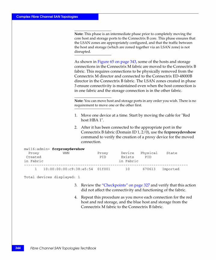
344
Complex Fibre Channel SAN Topologies
Note: This phase is an intermediate phase prior to completely moving the core host and storage ports to the Connectrix B core. This phase ensures that the LSAN zones are appropriately configured, and that the traffic between the host and storage (which are zoned together via an LSAN zone) is not disrupted.
As shown in Figure 65 on page 343, some of the hosts and storage connections in the Connectrix M fabric are moved to the Connectrix B fabric. This requires connections to be physically removed from the Connectrix M director and connected to the Connectrix ED-48000B director in the Connectrix B fabric. The LSAN zones created in phase 3 ensure connectivity is maintained even when the host connection is in one fabric and the storage connection is in the other fabric.
Note: You can move host and storage ports in any order you wish. There is no requirement to move one or the other first.
1. Move one device at a time. Start by moving the cable for "Red host HBA 1".
2. After it has been connected to the appropriate port in the Connectrix B fabric (Domain ID 1, 2/0), use the fcrproxydevshow command to verify the creation of a proxy device for the moved connection.
mw116:admin> fcrproxydevshow Proxy WWN Proxy Device Physical State Created PID Exists PIDin Fabric in Fabric---------------------------------------------------------------------------- 1 10:00:00:00:c9:38:e5:54 01f001 10 670613 Imported
Total devices displayed: 1
3. Review the “Checkpoints” on page 327 and verify that this action did not affect the connectivity and functioning of the fabric.
4. Repeat this procedure as you move each connection for the red host and red storage, and the blue host and storage from the Connectrix M fabric to the Connectrix B fabric.
Fibre Channel SAN Topologies TechBook
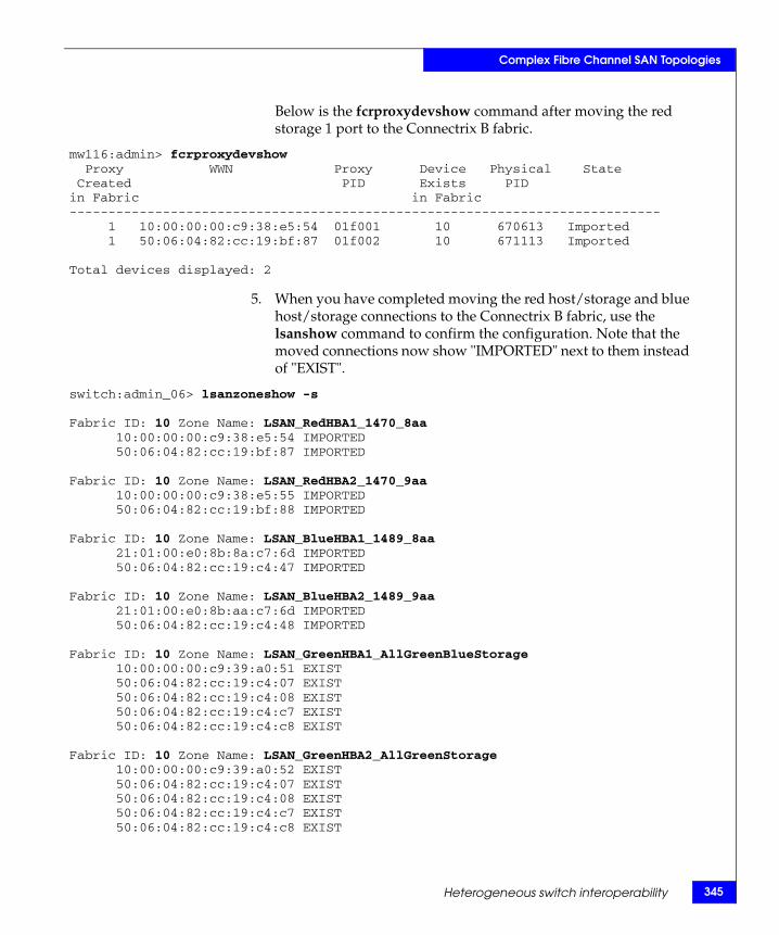
Complex Fibre Channel SAN Topologies
Below is the fcrproxydevshow command after moving the red storage 1 port to the Connectrix B fabric.
mw116:admin> fcrproxydevshow Proxy WWN Proxy Device Physical State Created PID Exists PIDin Fabric in Fabric---------------------------------------------------------------------------- 1 10:00:00:00:c9:38:e5:54 01f001 10 670613 Imported 1 50:06:04:82:cc:19:bf:87 01f002 10 671113 Imported
Total devices displayed: 2
5. When you have completed moving the red host/storage and blue host/storage connections to the Connectrix B fabric, use the lsanshow command to confirm the configuration. Note that the moved connections now show "IMPORTED" next to them instead of "EXIST".
switch:admin_06> lsanzoneshow -s
Fabric ID: 10 Zone Name: LSAN_RedHBA1_1470_8aa10:00:00:00:c9:38:e5:54 IMPORTED50:06:04:82:cc:19:bf:87 IMPORTED
Fabric ID: 10 Zone Name: LSAN_RedHBA2_1470_9aa10:00:00:00:c9:38:e5:55 IMPORTED50:06:04:82:cc:19:bf:88 IMPORTED
Fabric ID: 10 Zone Name: LSAN_BlueHBA1_1489_8aa21:01:00:e0:8b:8a:c7:6d IMPORTED50:06:04:82:cc:19:c4:47 IMPORTED
Fabric ID: 10 Zone Name: LSAN_BlueHBA2_1489_9aa21:01:00:e0:8b:aa:c7:6d IMPORTED50:06:04:82:cc:19:c4:48 IMPORTED
Fabric ID: 10 Zone Name: LSAN_GreenHBA1_AllGreenBlueStorage10:00:00:00:c9:39:a0:51 EXIST50:06:04:82:cc:19:c4:07 EXIST50:06:04:82:cc:19:c4:08 EXIST50:06:04:82:cc:19:c4:c7 EXIST50:06:04:82:cc:19:c4:c8 EXIST
Fabric ID: 10 Zone Name: LSAN_GreenHBA2_AllGreenStorage10:00:00:00:c9:39:a0:52 EXIST50:06:04:82:cc:19:c4:07 EXIST50:06:04:82:cc:19:c4:08 EXIST50:06:04:82:cc:19:c4:c7 EXIST50:06:04:82:cc:19:c4:c8 EXIST
Heterogeneous switch interoperability 345
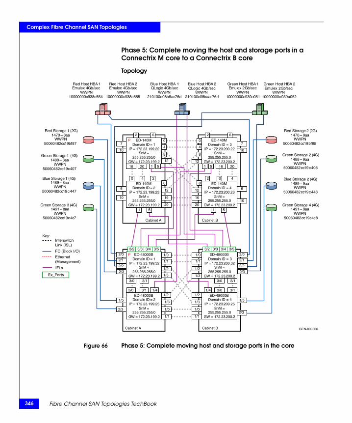
346
Complex Fibre Channel SAN Topologies
Phase 5: Complete moving the host and storage ports in a Connectrix M core to a Connectrix B core
Topology
Figure 66 Phase 5: Complete moving host and storage ports in the core
GEN-000506
Domain ID = 1 IP = 172 . 23 . 199 . 22
SnM = 255 . 255 . 255 . 0
GW = 172 . 23 . 199 . 2
Domain ID = 2IP = 172.23.199.23
SnM = 255.255.255.0
GW = 172.23.199.2
Domain ID = 4IP = 172.23.200.23
SnM = 255.255.255.0
GW = 172.23.200.2
Domain ID = 3IP = 172.23.200.22
SnM = 255.255.255.0
GW = 172.23.200.2
Cabinet A Cabinet B
Red Host HBA 1 Emulex 4 Gb / sec
WWPN 10000000 c 938 e 554
Red Host HBA 2 Emulex 4 Gb / sec
WWPN 10000000 c 938 e 555
Green Host HBA 1Emulex 2 Gb/sec
WWPN10000000c939a051
Green Host HBA 2Emulex 2 Gb/sec
WWPN10000000c939a052
Blue Host HBA 1QLogic 4Gb/sec
WWPN210100e08b8ac76d
Blue Host HBA 2QLogic 4Gb /sec
WWPN210100e08baac76d
Red Storage 2 (2G)1470 – 9aa
WWPN50060482cc19bf88
Red Storage 1 (2G)1470 – 8 aa
WWPN 50060482 cc 19 bf 87
Green Storage 1 ( 4 G ) 1488 – 8 aa
WWPN 50060482 cc 19 c 407
Green Storage 2 (4G)1488 – 9aa
WWPN50060482cc19c408
Blue Storage 1 ( 4 G ) 1489 – 8 aa
WWPN 50060482 cc 19 c 447
Blue Storage 2 (4G)1489 – 9aa
WWPN50060482cc19c448
Green Storage 3 ( 4 G ) 1491 – 8 aa
WWPN 50060482 cc 19 c 4 c 7
Green Storage 4 (4G)1491 – 9aa
WWPN50060482cc19c4c8
2
1 5
1 5 1 5
1 5
2
0 0
4 4
6 6
0 4 2 2 0 4
16 20
16
20
12
8
8
12
8
12
8
12
16
20
7
10
6
10
16 20
7
10
6
10
P
Domain ID = 1IP = 172.23.199.32
SnM = 255.255.255.0
GW = 172.23.199.2
Domain ID = 2IP = 172.23.199.25
SnM = 255.255.255.0
GW = 172.23.199.2
Domain ID = 4IP = 172.23.200.25
SnM = 255.255.255.0
GW = 172.23.200.2
Domain ID = 3IP = 172.23.200.32
SnM = 255.255.255.0
GW = 172.23.200.2
Cabinet A Cabinet B
1/0
3/53/43/33/2 3/53/43/33/2
1/0
1/1 1/1
3/0 3/1 1/4 1/4 3/0 3/1
3/0 3/1
1/0
1/1
1/3
1/2
1/2
1/3
1/2
1/3
1/2
1/3
1/0
1/1
2/2
2/1
2/0
2/3
2/2
2/1
2/0
2/3
1/5
2/3
3/0 3/1
1/5
2/3
P
Key:InterswitchLink (ISL)
FC (Block I/O)
Ethernet(Management)
Ex_Ports
IFLs
ED-140M
ED-140M
ED-140M
ED-140M
ED-48000B
ED-48000B
ED-48000B
ED-48000B
Fibre Channel SAN Topologies TechBook
Complex Fibre Channel SAN Topologies
Phase 5 is an extension of “Phase 4: Moving half of the host and storage ports from a Connectrix M fabric to a Connectrix B fabric” on page 343.
After validating that stable fabrics exists after the completion of Phase 4, execute Phase 5 by pulling the remaining host and storage connections in the Connectrix M fabric and transferring them to the Connectrix B fabric.
Review the “Checkpoints” on page 327.
Complete migration to the Connectrix B fabric
At the end of case study 6, a full migration from a Connectrix M fabric to a Connectrix B fabric is completed. During the migration, SAN routing was deployed using interfabric links (IFL) between switches in both fabrics without disruption to application I/O.
The Connectrix M fabric can be removed after all devices have been moved to the Connectrix B fabric. This results in a fully operational Connectrix B fabric. At no time was there a fabric outage, nor any disruption to application IO, as devices were moved from the Connectrix M to the Connectrix B fabric.
The zones in the Connectrix B fabric were initially created with the special "LSAN_" prefix. When all devices are moved to the Connectrix B fabric, you may wish to rename the Connectrix B zones by removing the "LSAN_" prefix in the zone names. his prevents later confusion while managing the Connectrix B fabric since no LSAN zones are required.
If desired, the SAN router can be removed from the Connectrix B fabric as well, or it can be used to connect to any other Connectrix M or Connectrix B fabrics as desired.
Warnings or caveats
◆ Please refer to EMC Knowledgebase solution emc149735 for all interop issues.
Cisco Inter VSAN Routing (IVR) in a heterogeneous environmentCisco Inter VSAN Routing allows the Connectrix MDS series switches to consolidate multiple physical fabrics of different modes into a single physical fabric separated by VSANs while leveraging IVR to provide the necessary connectivity between the VSANs on a per-device basis. IVR provides additional benefits, including the
Heterogeneous switch interoperability 347
348
Complex Fibre Channel SAN Topologies
ability to connect a core PID 0 Connectrix B switch to a core PID 1 Connectrix B switch. Normally, an outage would be required to change the core PID of one of the switches. IVR allows the Connectrix MDS switch to act as a conduit between two different legacy switch interop modes.
WARNING
RDI mode must be explicitly enabled in IVR configurations which will use interop mode 1 to connect to non-Cisco FC switches. RDI mode is automatically enabled in configurations that use interop mode 2, 3 or 4. According to documentation from Cisco:When third-party switches are involved in an IVR configuration, use the ivr virtual-fcdomain-add command to enable RDI mode, as third-party switches do not often query the remote name server unless it is present in the domain list. Issuing this command causes all virtual domains to appear in the domain list. This command should only be issued in the VSANs (border VSANs) in which the specified switch is present. Issuing the ivr virtual-fcdomain-add command is required only in edge or border VSANs. It is not required in MDS native VSANs.
Set up IVR with interop mode
To set up IVR with interop mode VSANs:
1. Establish ISL connectivity between the Connectrix MDS switch and the third-party switch. VSANs, ISLs, and third-party switches should be configured as specified in the appropriate sections of this document.
2. Enable IVR and configure IVR topologies, zones, and zone sets on the IVR-enabled Connectrix MDS switch. IVR zoning must be managed from the Connectrix MDS only.
Note: In all cases, only manage IVR Zoning from the Connectrix MDS.
To configure IVR and IVR zones using the IVR Zone Wizard in Cisco Fabric Manager:
a. Click the IVR Zone Wizard icon in the Zone toolbar.
b. Select the VSANs that will participate in IVR in the fabric.
c. Select the end devices that will communicate over IVR.
Fibre Channel SAN Topologies TechBook

Complex Fibre Channel SAN Topologies
Note: Fabric Manager displays an error message if all the switches participating in IVR do not have unique Domain IDs.These switches must be reconfigured before configuring IVR.
d. Enter the VSAN ID of the VSAN you want to use as the transit VSAN between the VSANs selected for the IVR zone, and then click Next.
e. Optionally, configure a unique AFID for switches in the fabric that have non-unique VSAN IDs in the Select AFID dialog box.
f. Verify the transit VSAN, or configure the transit VSAN, if Fabric Manager cannot find an appropriate transit VSAN.
g. Set the IVR zone and IVR zone set (now or later) using the Edit Local Full Zone database from the Zone menu.
Please note:
– A zone corresponding to each active IVR zone is automatically created in each edge VSAN specified in the active IVR zone. All WWPNs in the IVR zone are members of these zones in each VSAN.
– Sometimes zone names beginning with prefix IVRZ and a zone set with name nozoneset appear in logical view. The zones with prefix IVRZ are IVR zones that get appended to regular active zones. The prefix IVRZ is appended to active IVR zones by the system. Similarly the zone set with name nozonese is an IVR active zone set created by the system if no active zone set is available for that VSAN, and if the ivrZonesetActivateForce flag is enabled on the switch.
h. Verify all steps that Fabric Manager uses to configure IVR in the fabric.
i. Click Finish if you want to enable the configured IVR topology and the associated IVR zones and IVR zone set.
j. The Save Configuration dialog box appears. The configuration of the master switch to be copied to other IVR-enabled switches may be saved. Depending on what is required, click Continue Activation” or click Cancel.
k. Click Finish.
Heterogeneous switch interoperability 349
350
Complex Fibre Channel SAN Topologies
For more detailed information on setting up different types of IVR or IVR-NAT configurations please refer to the documentation located at http://www.cisco.com.
Warnings or caveats
Please refer to EMC Knowledgebase solution emc149735 for all interop issues.
◆ Brocade switches cannot see IVR-enabled devices if NAT is enabled. IVR-1 or IVR without NAT works fine.
◆ If the IBM Blade Center is involved in an IVR configuration, use the ivr virtual-fcdomain-add command since specified switches do not query the remote name server unless it is present in the domain list. Issuing this command causes all virtual domains to appear in the domain list. This command should only be issued in the VSANs (border VSANs) in which the specified switch is present. With Connectrix MDS SAN-OS Release 1.3(4a), issue the ivr virtual-fcdomain-add command only in edge or border VSANs. Do not issue the command in transit VSANs. If multiple IVR-enabled switches exist in an edge or border VSAN, the following error message may be displayed in the system messages: (DEVICE_ON_WRONG_NATIVE_VSAN). This message can be ignored.
◆ When routing between an interop mode 1 or 4 VSAN and a non-interop mode 1 or 4 VSAN, make sure that there are no domains in the native, or legacy switch interop modes 2 or 3 VSANs that are outside of the 97 to 127 range. Domains outside of this range cannot be created in the interop mode 1 VSAN. This is not a limitation of IVR-1, but a restriction imposed upon the configuration by interop mode 1. Since IVR-2 rewrites the Domain ID and FCID of the device in the non-interop mode 1 or 4 VSAN, this is not an issue.
◆ If an IVR zone set is active in a VSAN running in an interop mode, regular zone changes (such as zone set activation, reactivation or deactivation for zones that do not require IVR services) should always be initiated from the IVR border switch (the IVR-enabled Connectrix MDS 9000 switch) for that VSAN. This prevents disruption to ongoing traffic between IVR initiators and targets that are allowed by both the previous active zone set and the new active zone set. Otherwise, traffic disruption occurs, and a zone change can also fail because only the border switch has the IVR configuration for that VSAN.
Fibre Channel SAN Topologies TechBook
Complex Fibre Channel SAN Topologies
◆ Domain conflicts can occur between switches in different VSANs and thus the Domain ID of a switch needs to be reset to avoid a Domain ID clash with a switch in a different VSAN (which is accessible with IVR).
◆ No zone names on a third-party switch participating in an interop environment with IVR can start with IVRZ. All IVR zoning must be managed through the Cisco switches.
Vendor-specific switch settings for interop
This section provides a more generic set of instructions or non-default settings that need to be configured on all switches belonging to a specific vendor type before they are introduced into a heterogeneous switched fabric. In addition, this section also provides the techniques, best practices, caveats, and unavailable features for a switch interoperability implementation.
Checklist
This checklist can be used to serve as a tool for completing all steps before actually merging fabrics.
◆ Verify that each switch has a unique Domain ID. When merging fabrics, ensure that there are no duplicate Domain IDs among all switches that will be part of the merged fabric.
◆ Verify that all switches have been set up to work in a supported interop mode.
◆ Verify that the E_D_TOV and R_A_TOV are set the same on all switches that will be part of the new fabric. (By default, they should all be the same; if necessary, refer to the appropriate user manual for information on how to set up operating parameters.)
Note: Switches use different units to represent the same values; for example a value of 2000 on a Brocade switch or Cisco switch is the equivalent of 20 on a Brocade M series switch.
◆ Verify that the active zone set has been checked (with the respective switch fabric management tools) and does not contain illegal characters.
Heterogeneous switch interoperability 351
352
Complex Fibre Channel SAN Topologies
Note: There are limitations on what characters can be used for zone names. The name needs to start with a letter and then can be any combination of upper and lowercase letters as well as numbers and underscores. Everything else, including dashes, periods, or spaces should be avoided.
◆ If a switch is not operational and the zoning definition on that switch is not required, be sure to clear the zoning configuration on that switch.
◆ If a switch is operational and the zoning configuration on that switch is required, be sure to check that there are no duplicate active zone names. If there are duplicate zone names, rename one of the zones.
◆ Ensure that all switches are configured with WWN zoning.
◆ Ensure that all switches comply with proper zone naming.
◆ Back up the switch configuration by issuing the appropriate commands.
Some of the items on this checklist can be considered as recommended best practices to configure a stable interoperable environment with minimal disruption to existing data flow, if any.
Recommended bestpractices
◆ Set the Domain IDs rather than allowing the fabric to set them.
◆ Set the core switch as a principal switch. This reduces Class F traffic by ensuring that it goes directly from core to edge. For example, if an edge switch is the principal switch, build fabric traffic must go through the core to get from edge to edge.
◆ In a vendor switch migration from either Brocade or Brocade M series, leave Brocade or Brocade M series switches in their native modes and use Cisco’s legacy modes, Interop-3 and Interop-4 (only if supported) for a non-disruptive and seamless migration.
Note: At the time of this release, EMC supports Interop-4 using RPQ for migration purposes only. Refer to the EMC Support Matrix for the most up-to-date support.
◆ Manage all IVR-based zoning in a heterogeneous environment with Cisco switches using the Cisco Fabric Manager. No zones or zone sets created on the Brocade or Brocade M series switch, or any other vendor switch in an IVR setup can start with an IVRZ prefix.
Fibre Channel SAN Topologies TechBook
Complex Fibre Channel SAN Topologies
◆ Refer to the specific vendor interoperability caveats before setting up an interoperable environment. Use only the correct and supported version of switch firmware and Fabric Management software.
Configuration of non-default settings onsupported vendor
switches
The vendor-specific non-default settings that must be enabled on each of the supported vendor switches before introducing them into an interop environment follow:
Configure a Brocade switch
Telnet can be used to change the Domain ID or set the interop mode on a Brocade switch. These actions require disabling the switch; therefore, plan accordingly.
Principal switch setting
To configure a Brocade director switch in the core of a fabric as the principal switch, issue the fabricprincipal command on the switch CLI running FOS 4.x and higher. This setting becomes active on the next reboot, or after the build fabric (BF) event.
Configure the Domain ID
To set the preferred Domain ID:
1. Start a Telnet session.
2. Enter switchdisable to disable the switch.
3. Enter configure.
4. Answer yes to the Fabric parameters questions.
5. The first field, Domain, is the Domain ID, in the range 97 through 127, with these exceptions:
• The lowest numbers are generally allocated to the Brocade M series switches if any, in the fabric.
• Domain ID 104 (decimal 8) is reserved by HP.
Starting with 97, allow one number for each Brocade M series switch. Then assign the next available number to the Brocade switch, and number the remaining Brocade switches in order (skipping 104).
Accept all default values for the other parameters in this section, and answer No to all other sections until the switch enters the phase where it commits the new Domain ID to flash.
Heterogeneous switch interoperability 353
354
Complex Fibre Channel SAN Topologies
The Domain ID becomes the value that the switch requests when attempting to join the fabric from an offline mode.
6. Enter switchenable.
Setting the interopmode
To set the interop mode:
1. Start a Telnet session
2. Enter switchdisable.
3. Enter interopmode 1to enable interopmode: interopmode 1.
4. Enter reboot or fastboot.
Configure a Cisco switch
To configure an MDS series switch the Domain ID and persistent FCIDs must be set, in addition to creating an interop VSAN. If you configure the switch as a core switch, you must set the switch priority.
To create an interop VSAN:
1. Log into Cisco Fabric Manager.
2. In the left pane, expand All VSANs.
3. Select VSAN Attributes.
4. In the right pane, select Create row.
5. Uncheck any MDS series switch that will not participate in the new VSAN.
6. In the VSAN field, assign a VSAN ID, 2 through 4093.
7. If desired, give the VSAN a name.
8. Leave Loadbalancing at default.
9. Set InterOperValue to interop-1.
Note: Interop-2 and Interop-3 are the legacy Brocade modes and Interop-4 is the legacy Brocade M series mode, and can be set depending on the requirement.At the time of this release, EMC supports Interop-4 using RPQ for migration purposes only. Please refer to the EMC Support Matrix for the most up-to-date support.
10. Click Create. The new VSAN appears in the left pane.
Fibre Channel SAN Topologies TechBook
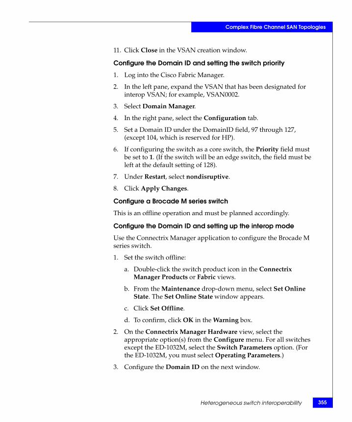
Complex Fibre Channel SAN Topologies
11. Click Close in the VSAN creation window.
Configure the Domain ID and setting the switch priority
1. Log into the Cisco Fabric Manager.
2. In the left pane, expand the VSAN that has been designated for interop VSAN; for example, VSAN0002.
3. Select Domain Manager.
4. In the right pane, select the Configuration tab.
5. Set a Domain ID under the DomainID field, 97 through 127, (except 104, which is reserved for HP).
6. If configuring the switch as a core switch, the Priority field must be set to 1. (If the switch will be an edge switch, the field must be left at the default setting of 128).
7. Under Restart, select nondisruptive.
8. Click Apply Changes.
Configure a Brocade M series switch
This is an offline operation and must be planned accordingly.
Configure the Domain ID and setting up the interop mode
Use the Connectrix Manager application to configure the Brocade M series switch.
1. Set the switch offline:
a. Double-click the switch product icon in the Connectrix Manager Products or Fabric views.
b. From the Maintenance drop-down menu, select Set Online State. The Set Online State window appears.
c. Click Set Offline.
d. To confirm, click OK in the Warning box.
2. On the Connectrix Manager Hardware view, select the appropriate option(s) from the Configure menu. For all switches except the ED-1032M, select the Switch Parameters option. (For the ED-1032M, you must select Operating Parameters.)
3. Configure the Domain ID on the next window.
Heterogeneous switch interoperability 355
356
Complex Fibre Channel SAN Topologies
4. To set the Interopmode and the Switch Priority, go back to the Configure menu, and select the Operating Parameters, Fabric Parameters option. This displays the Configure Fabric Parameters dialog box. The Switch Priority can be set as Principal or Default depending on the functionality. The director with the lower WWN becomes the principal switch, if the principal switch becomes unavailable.
You can set interopmode to Open Fabric 1.0 if the switch is brought into an interop environment with Brocade or the Cisco in Interop-1.
When finished, click Activate.
5. Set the switch to online.
Unavailable features Some of the features that are available prior to enabling the interoperability mode on FC switches are subsequently disabled. For example, when interop mode is enabled on Brocade switches, it disables domain/port-based zoning, Virtual Channel flow control, trunking, etc. This creates operational challenges for storage administrators who have to give up functionality in order to build heterogeneous fabrics.
Some features that are not available on the specific vendor switches when operating in Interop Fabric Mode include:
Brocade switches
◆ QuickLoop
◆ QuickLoop Fabric Assist
◆ Remote Switch
◆ Extended Fabrics
◆ Trunking
◆ Secure Fabric OS
◆ Alias Server
◆ Platform Service
◆ Virtual Channels
◆ FCIP
Fibre Channel SAN Topologies TechBook
Complex Fibre Channel SAN Topologies
Cisco switches
◆ TE_ports (trunking expansion ports) and Port-Channels cannot be used to connect MDS to non-MDS switches. However, TE_ports and Port Channels can still be used to connect an MDS to other MDS switches even when in Cisco Fabric mode VSANs.
◆ The Quality of Service feature is intended to provide nodes with high bandwidth needs and greater access to the fabric resources. Quality of Service is applied end to end (host to storage), and can be implemented only if host and storage are attached to MDS models.
Brocade M series switches
◆ Show route (where targets or initiators are located on Brocade or Cisco switches)
◆ Show zone (where members are located on Brocade or Cisco switches)
◆ Fabric Binding
◆ Enterprise Fabric Mode
◆ SANtegrity (with the exception of Switch Binding)
Supportedinteroperability
modes
Table 6 on page 358 shows EMC-tested modes. Read the table as follows:
The vendor switch operating in the respective mode listed in the two left columns can interoperate with the vendor switch in the top row operating in the mode specified by the intersection of that row and column.
Note: For the most current support information, refer to the EMC Support Matrix.
Heterogeneous switch interoperability 357
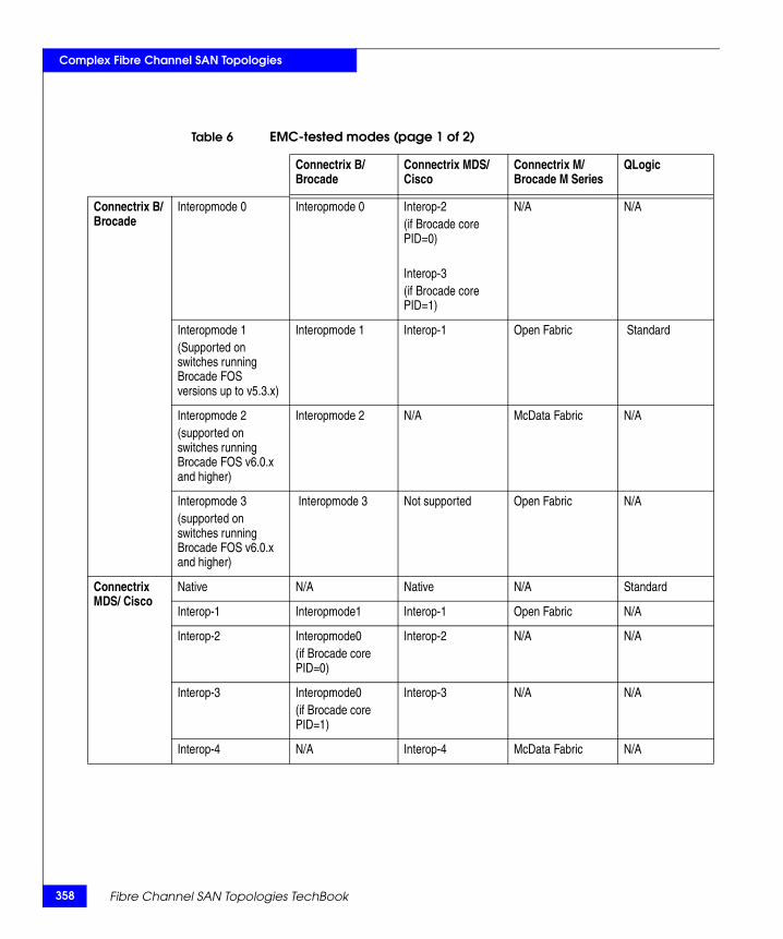
358
Complex Fibre Channel SAN Topologies
Table 6 EMC-tested modes (page 1 of 2)
Connectrix B/ Brocade
Connectrix MDS/ Cisco
Connectrix M/ Brocade M Series
QLogic
Connectrix B/ Brocade
Interopmode 0
Interopmode 0 Interop-2(if Brocade core PID=0)
Interop-3(if Brocade core PID=1)
N/A N/A
Interopmode 1(Supported on switches running Brocade FOS versions up to v5.3.x)
Interopmode 1 Interop-1 Open Fabric Standard
Interopmode 2(supported on switches running Brocade FOS v6.0.x and higher)
Interopmode 2 N/A McData Fabric N/A
Interopmode 3(supported on switches running Brocade FOS v6.0.x and higher)
Interopmode 3 Not supported Open Fabric N/A
Connectrix MDS/ Cisco
Native N/A Native N/A Standard
Interop-1 Interopmode1 Interop-1 Open Fabric N/A
Interop-2 Interopmode0(if Brocade core PID=0)
Interop-2 N/A N/A
Interop-3 Interopmode0(if Brocade core PID=1)
Interop-3 N/A N/A
Interop-4 N/A Interop-4 McData Fabric N/A
Fibre Channel SAN Topologies TechBook
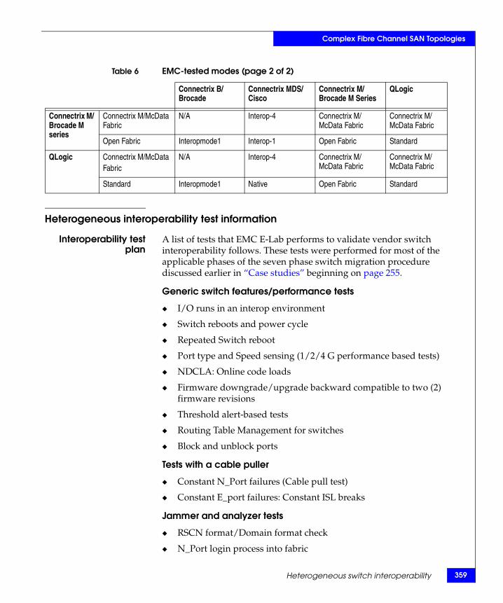
Complex Fibre Channel SAN Topologies
Heterogeneous interoperability test information
Interoperability testplan
A list of tests that EMC E-Lab performs to validate vendor switch interoperability follows. These tests were performed for most of the applicable phases of the seven phase switch migration procedure discussed earlier in “Case studies” beginning on page 255.
Generic switch features/performance tests
◆ I/O runs in an interop environment
◆ Switch reboots and power cycle
◆ Repeated Switch reboot
◆ Port type and Speed sensing (1/2/4 G performance based tests)
◆ NDCLA: Online code loads
◆ Firmware downgrade/upgrade backward compatible to two (2) firmware revisions
◆ Threshold alert-based tests
◆ Routing Table Management for switches
◆ Block and unblock ports
Tests with a cable puller
◆ Constant N_Port failures (Cable pull test)
◆ Constant E_port failures: Constant ISL breaks
Jammer and analyzer tests
◆ RSCN format/Domain format check
◆ N_Port login process into fabric
Connectrix M/ Brocade M series
Connectrix M/McData Fabric
N/A Interop-4 Connectrix M/ McData Fabric
Connectrix M/ McData Fabric
Open Fabric Interopmode1 Interop-1 Open Fabric Standard
QLogic Connectrix M/McDataFabric
N/A Interop-4 Connectrix M/ McData Fabric
Connectrix M/ McData Fabric
Standard Interopmode1 Native Open Fabric Standard
Table 6 EMC-tested modes (page 2 of 2)
Connectrix B/ Brocade
Connectrix MDS/ Cisco
Connectrix M/ Brocade M Series
QLogic
Heterogeneous switch interoperability 359
360
Complex Fibre Channel SAN Topologies
◆ Sending corrupted frames to switch
◆ Sending out of order frames to switch
◆ Loss of synchronization
Zoning
◆ Member addition to/removal from zone
◆ Mixed port and WWN zoning tests
◆ Creating/deleting zones
◆ Fabric merge/conflict tests for same zone set name, different zone names, same zone members
◆ Fabric merge/conflict tests for different zone tests, different zone names, different zone members
◆ Fabric merge/conflict tests for same zone set names, same zone names, different zone members
Fabric: Principal switch test
◆ Principal switch selection with priority settings
◆ Principal switch selection with no priority settings
Command line
◆ Performance monitoring
◆ Switch configuration
External Host based
◆ Host power cycle
◆ Host Reboot
Automated patchpanel
Throughout this FC-SW based interoperability section, several topologies have been discussed that can be stepped through sequentially. Normally, the initial setup and incremental changes require a number of hours to configure. In the past, this setup time proved to be a significant barrier to performing frequent interoperability testing, and customer-requested migration processes at E-Lab.
To reduce setup time and help facilitate the migration testing, E-Lab recently purchased a Brocade M series UCS 2910 Automated Patch Panel. This enables E-Lab to approach an interop deployment in stages, similar to the way deployment is performed by an end user.
Fibre Channel SAN Topologies TechBook
Complex Fibre Channel SAN Topologies
E-Lab can also now take point-in-time snapshots of any configuration for future reference when confirming a fix or reproducing a problem.
More about the UCS 2910
The UCS 2910 is an Optical to Electrical to Optical (O-E-O) physical layer switch that handles all serial communication protocols up to 2 GB/s. (4 GB/s interfaces are in development.) It allows multiple users to control subsets of ports. The user interface allows for simple point-and-click connections for single connections as well as configuration backup and restore functions for multiple connections.
Heterogeneous switch interoperability 361
362
Complex Fibre Channel SAN Topologies
Distance extension case studiesThis section offers two distance extension case studies:
◆ “Case study #1: Configuring an MP-1620M running EOSi 5.1” on page 362
◆ “Case study #2: FCIP configuration and setup” on page 390
Case study #1: Configuring an MP-1620M running EOSi 5.1This case study illustrates the process of migrating from an environment that utilizes iFCP (MP-1620M or MP-2640M) for distance extension to one that uses FCIP (MP-7500B or PB-48K-18i) for the same purpose. This migration process will be disruptive for short periods of time so proper planning and expectation setting will be essential for success. Frequently, distance extension is used for disaster recovery purposes; therefore SRDF or MirrorView will be used in these examples.
In order to better illustrate the migration process, this example will first provide the setup steps required to configure the iFCP environment. Once iFCP traffic has been established, the process of configuring the FCIP links and adding the MP-7500B or PB-48K-18i to the fabric will be described.
Assumptions
◆ MP-1620Ms or MP-2640Ms are running EOSi 5.1 and SANvergence Manager Enterprise Edition Version 5.0.
◆ The DS-16Ms are running EOSc 9.6.2 and are being managed by Connectrix Manager 9.6.1.
Prerequisites
Before attempting to implement in the Customers environment, the following must have been completed:
◆ Install SANvergence Manager 5.0 on a host that has IP connectivity to the MP-1620Ms management interfaces.
◆ A laptop with a Serial Port and a Null modem cable are needed to configure the management interfaces on the MP-1620Ms.
◆ Complete the Worksheet shown in Figure 75 on page 394.
The worksheet will be used to feed the process of configuring the FC switches and MP-1620Ms.
Fibre Channel SAN Topologies TechBook
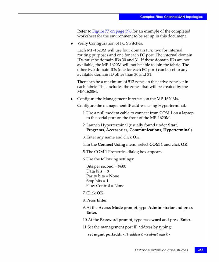
Complex Fibre Channel SAN Topologies
Refer to Figure 77 on page 396 for an example of the completed worksheet for the environment to be set up in this document.
◆ Verify Configuration of FC Switches.
Each MP-1620M will use four domain IDs, two for internal routing purposes and one for each FC port. The internal domain IDs must be domain IDs 30 and 31. If these domain IDs are not available, the MP-1620M will not be able to join the fabric. The other two domain IDs (one for each FC port) can be set to any available domain ID other than 30 and 31.
There can be a maximum of 512 zones in the active zone set in each fabric. This includes the zones that will be created by the MP-1620M.
◆ Configure the Management Interface on the MP-1620Ms.
Configure the management IP address using Hyperterminal.
1. Use a null modem cable to connect from COM 1 on a laptop to the serial port on the front of the MP-1620M.
2. Launch Hyperterminal (usually found under Start, Programs, Accessories, Communications, Hyperterminal).
3. Enter any name and click OK.
4. In the Connect Using menu, select COM 1 and click OK.
5. The COM 1 Properties dialog box appears.
6. Use the following settings:
Bits per second = 9600Data bits = 8Parity bits = NoneStop bits = 1Flow Control = None
7. Click OK.
8. Press Enter.
9. At the Access Mode prompt, type Administrator and press Enter.
10.At the Password prompt, type password and press Enter.
11.Set the management port IP address by typing:
set mgmt portaddr <IP address><subnet mask>
Distance extension case studies 363
364
Complex Fibre Channel SAN Topologies
Refer to Management IP address section shown in the worksheet shown in Figure 75 on page 394 for IP address and subnet mask information.
12.Set up a permroute to the gateway using the command:
set mgmt permroute <addr><mask><gateway>
In this example, the command set mgmt permroute 128.0.0.0 128.0.0.0 172.23.186.2 will forward all packets not on the local network to the gateway.
Refer to Management IP address section shown in the worksheet shown in Figure 75 on page 394 for the worksheet for Gateway information.
13.Save the configuration by typing:
save
14.Reboot the system by typing:
reset system
15.Repeat these steps on other MP-1620Ms as necessary.
Fibre Channel SAN Topologies TechBook
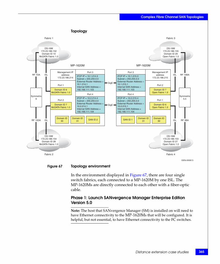
Complex Fibre Channel SAN Topologies
Topology
Figure 67 Topology environment
In the environment displayed in Figure 67, there are four single switch fabrics, each connected to a MP-1620M by one ISL. The MP-1620Ms are directly connected to each other with a fiber-optic cable.
Phase 1: Launch SANvergence Manager Enterprise Edition Version 5.0
Note: The host that SANvergence Manager (SM) is installed on will need to have Ethernet connectivity to the MP-1620Ms that will be configured. It is helpful, but not essential, to have Ethernet connectivity to the FC switches.
Port 3
MP-1620M MP-1620M
Port 4
Management IPaddress
172.23.186.214
Port 3
Port 4
Management IPaddress
172.23.186.215
DS-16M172.23.186.155Domain ID 29
Open Fabric 1.0
DS-16M172.23.186.153Domain ID 27
Open Fabric 1.0
ISL RF 14BA
ISL RF 3BA
Symmetrix5.5
ISLRF 7DA
ISLRF 10DA
Symmetrix6
Fabric 3
Fabric 4
GEN-000813
Fabric 1
Fabric 2
DS-16M172.23.186.152Domain ID 10
McDATA Fabric 1.0
DS-16M172.23.186.154Domain ID 28
McDATA Fabric 1.0
GigE
GigE
iFCP IP = 10.1.214.3Subnet = 255.255.0.0External Router Address =10.1.214.1Internal SAN Address =192.168.111.103
iFCP IP = 10.2.214.4Subnet = 255.255.0.0External Router Address =10.2.214.1Internal SAN Address =192.168.111.104
SAN ID 2Domain ID
31Domain ID
30
Domain ID 7McDATA Fabric 1.0
Port 1
Port 2
iFCP IP = 10.1.215.3Subnet = 255.255.0.0External Router Address =10.1.215.1Internal SAN Address =192.168.111.103
iFCP IP = 10.2.215.4Subnet = 255.255.0.0External Router Address =10.2.215.1Internal SAN Address =192.168.111.104
SAN ID 1Domain ID
31Domain ID
30
Domain ID 6Open Fabric 1.0
Domain ID 7Open Fabric 1.0
Port 2
Port 1
Domain ID 6McDATA Fabric 1.0
Distance extension case studies 365
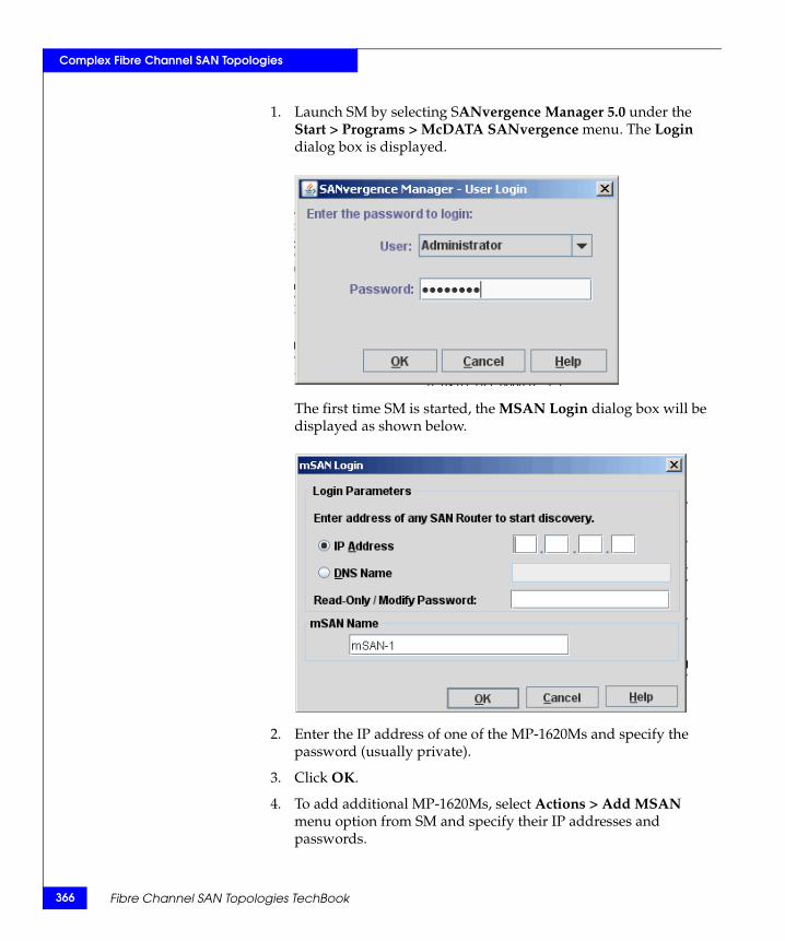
366
Complex Fibre Channel SAN Topologies
1. Launch SM by selecting SANvergence Manager 5.0 under the Start > Programs > McDATA SANvergence menu. The Login dialog box is displayed.
The first time SM is started, the MSAN Login dialog box will be displayed as shown below.
2. Enter the IP address of one of the MP-1620Ms and specify the password (usually private).
3. Click OK.
4. To add additional MP-1620Ms, select Actions > Add MSAN menu option from SM and specify their IP addresses and passwords.
Fibre Channel SAN Topologies TechBook
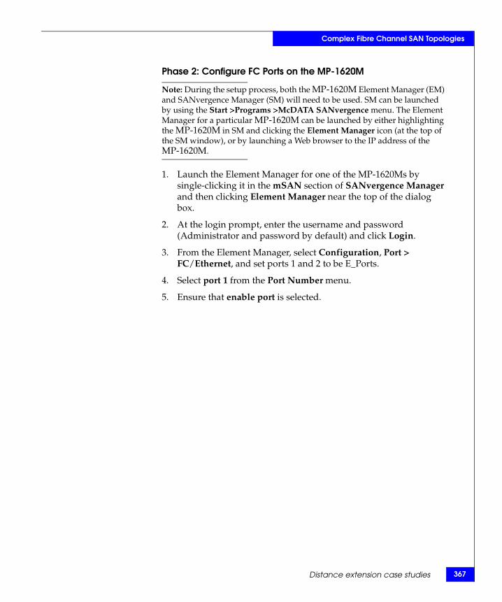
Complex Fibre Channel SAN Topologies
Phase 2: Configure FC Ports on the MP-1620M
Note: During the setup process, both the MP-1620M Element Manager (EM) and SANvergence Manager (SM) will need to be used. SM can be launched by using the Start >Programs >McDATA SANvergence menu. The Element Manager for a particular MP-1620M can be launched by either highlighting the MP-1620M in SM and clicking the Element Manager icon (at the top of the SM window), or by launching a Web browser to the IP address of the MP-1620M.
1. Launch the Element Manager for one of the MP-1620Ms by single-clicking it in the mSAN section of SANvergence Manager and then clicking Element Manager near the top of the dialog box.
2. At the login prompt, enter the username and password (Administrator and password by default) and click Login.
3. From the Element Manager, select Configuration, Port > FC/Ethernet, and set ports 1 and 2 to be E_Ports.
4. Select port 1 from the Port Number menu.
5. Ensure that enable port is selected.
Distance extension case studies 367
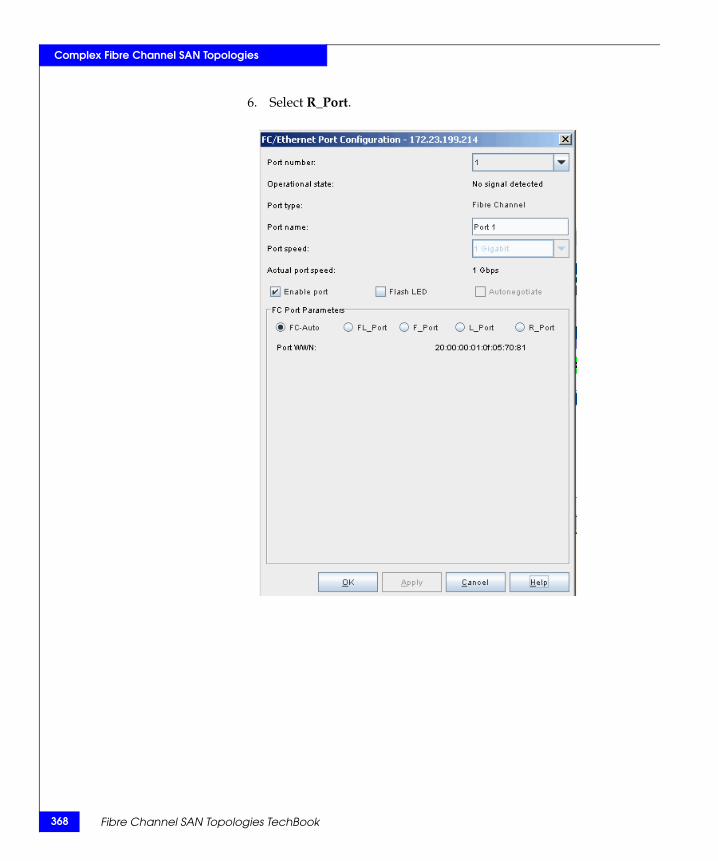
368
Complex Fibre Channel SAN Topologies
6. Select R_Port.
Fibre Channel SAN Topologies TechBook
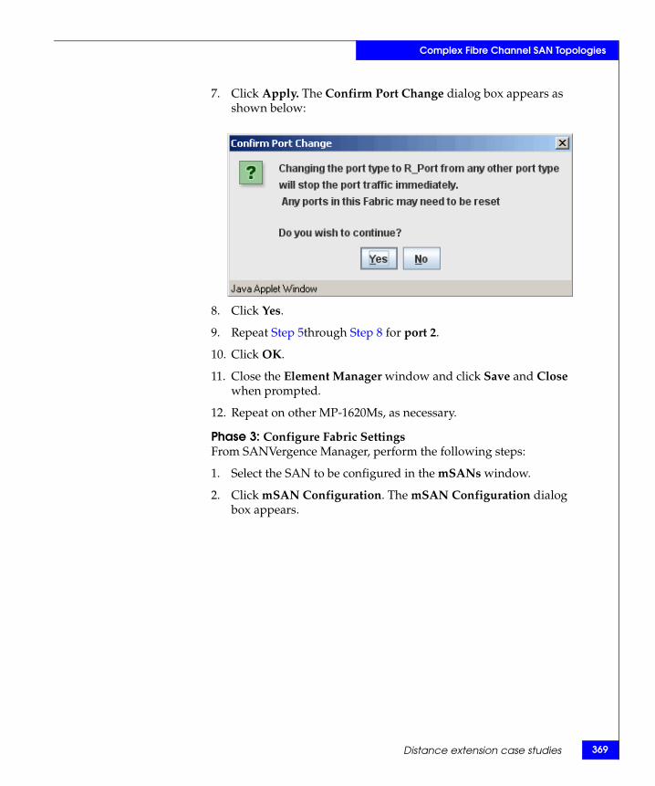
Complex Fibre Channel SAN Topologies
7. Click Apply. The Confirm Port Change dialog box appears as shown below:
8. Click Yes.
9. Repeat Step 5through Step 8 for port 2.
10. Click OK.
11. Close the Element Manager window and click Save and Close when prompted.
12. Repeat on other MP-1620Ms, as necessary.
Phase 3: Configure Fabric SettingsFrom SANVergence Manager, perform the following steps:
1. Select the SAN to be configured in the mSANs window.
2. Click mSAN Configuration. The mSAN Configuration dialog box appears.
Distance extension case studies 369
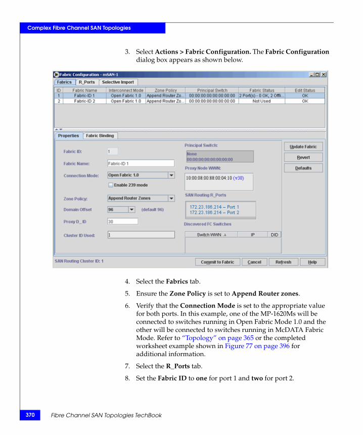
370
Complex Fibre Channel SAN Topologies
3. Select Actions > Fabric Configuration. The Fabric Configuration dialog box appears as shown below.
4. Select the Fabrics tab.
5. Ensure the Zone Policy is set to Append Router zones.
6. Verify that the Connection Mode is set to the appropriate value for both ports. In this example, one of the MP-1620Ms will be connected to switches running in Open Fabric Mode 1.0 and the other will be connected to switches running in McDATA Fabric Mode. Refer to “Topology” on page 365 or the completed worksheet example shown in Figure 77 on page 396 for additional information.
7. Select the R_Ports tab.
8. Set the Fabric ID to one for port 1 and two for port 2.
Fibre Channel SAN Topologies TechBook
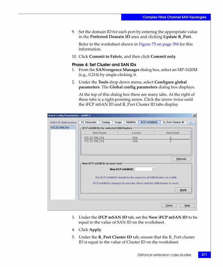
Complex Fibre Channel SAN Topologies
9. Set the domain ID for each port by entering the appropriate value in the Preferred Domain ID area and clicking Update R_Port.
Refer to the worksheet shown in Figure 75 on page 394 for this information.
10. Click Commit to Fabric, and then click Commit only.
Phase 4: Set Cluster and SAN IDs1. From the SANvergence Manager dialog box, select an MP-1620M
(e.g., 0.214) by single-clicking it.
2. Under the Tools drop down menu, select Configure global parameters. The Global config parameters dialog box displays.
At the top of this dialog box there are many tabs. At the right of these tabs is a right-pointing arrow. Click the arrow twice until the iFCP mSAN ID and R_Port Cluster ID tabs display.
3. Under the iFCP mSAN ID tab, set the New iFCP mSAN ID to be equal to the value of SAN ID on the worksheet.
4. Click Apply.
5. Under the R_Port Cluster ID tab, ensure that the R_Port cluster ID is equal to the value of Cluster ID on the worksheet.
Distance extension case studies 371
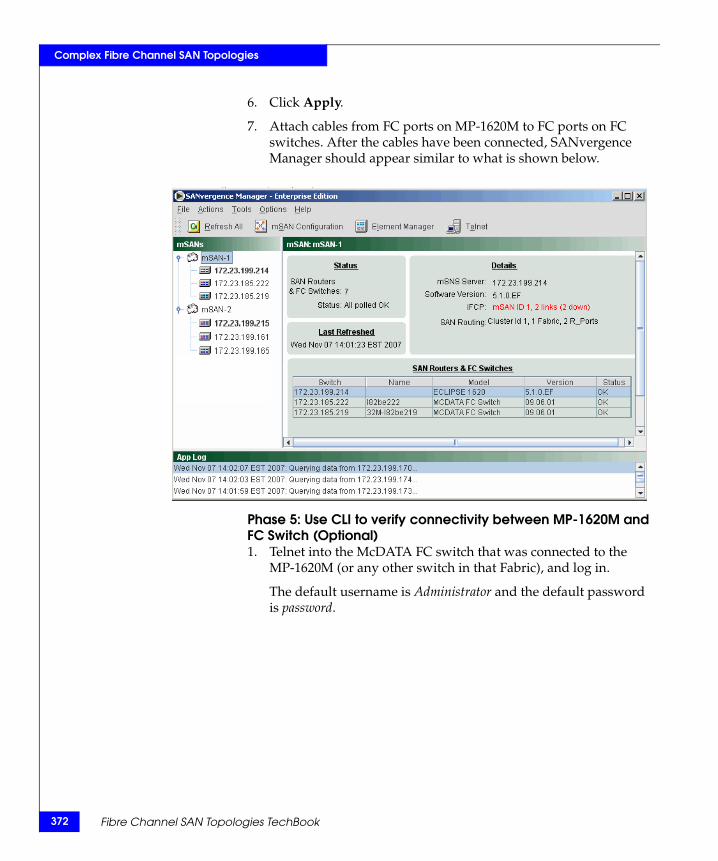
372
Complex Fibre Channel SAN Topologies
6. Click Apply.
7. Attach cables from FC ports on MP-1620M to FC ports on FC switches. After the cables have been connected, SANvergence Manager should appear similar to what is shown below.
Phase 5: Use CLI to verify connectivity between MP-1620M and FC Switch (Optional)1. Telnet into the McDATA FC switch that was connected to the
MP-1620M (or any other switch in that Fabric), and log in.
The default username is Administrator and the default password is password.
Fibre Channel SAN Topologies TechBook
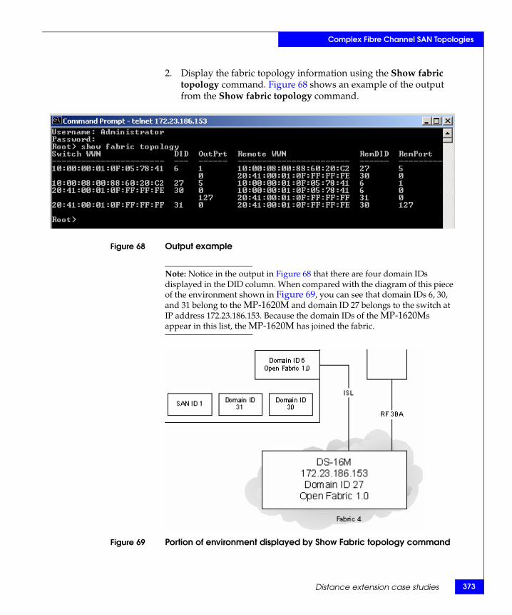
Complex Fibre Channel SAN Topologies
2. Display the fabric topology information using the Show fabric topology command. Figure 68 shows an example of the output from the Show fabric topology command.
Figure 68 Output example
Note: Notice in the output in Figure 68 that there are four domain IDs displayed in the DID column. When compared with the diagram of this piece of the environment shown in Figure 69, you can see that domain IDs 6, 30, and 31 belong to the MP-1620M and domain ID 27 belongs to the switch at IP address 172.23.186.153. Because the domain IDs of the MP-1620Ms appear in this list, the MP-1620M has joined the fabric.
Figure 69 Portion of environment displayed by Show Fabric topology command
Distance extension case studies 373
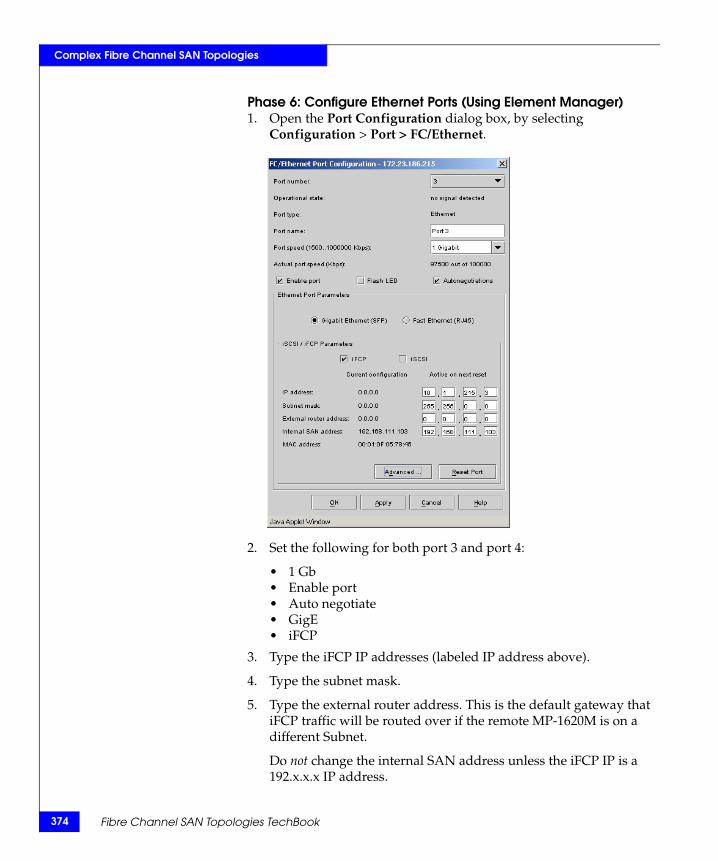
374
Complex Fibre Channel SAN Topologies
Phase 6: Configure Ethernet Ports (Using Element Manager)1. Open the Port Configuration dialog box, by selecting
Configuration > Port > FC/Ethernet.
2. Set the following for both port 3 and port 4:
• 1 Gb• Enable port• Auto negotiate• GigE• iFCP
3. Type the iFCP IP addresses (labeled IP address above).
4. Type the subnet mask.
5. Type the external router address. This is the default gateway that iFCP traffic will be routed over if the remote MP-1620M is on a different Subnet.
Do not change the internal SAN address unless the iFCP IP is a 192.x.x.x IP address.
Fibre Channel SAN Topologies TechBook
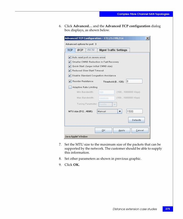
Complex Fibre Channel SAN Topologies
6. Click Advanced… and the Advanced TCP configuration dialog box displays, as shown below.
7. Set the MTU size to the maximum size of the packets that can be supported by the network. The customer should be able to supply this information.
8. Set other parameters as shown in previous graphic.
9. Click OK.
Distance extension case studies 375
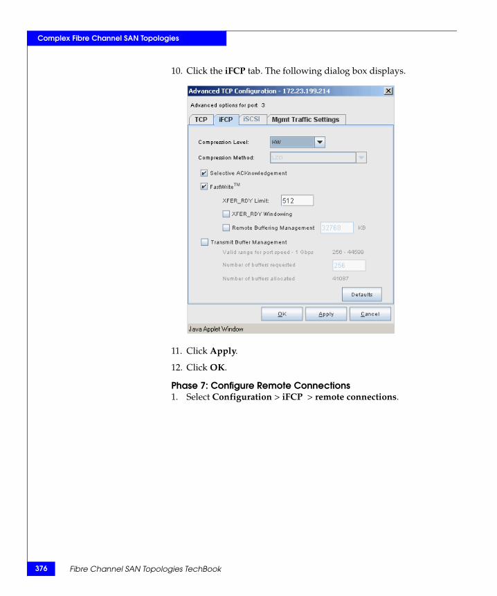
376
Complex Fibre Channel SAN Topologies
10. Click the iFCP tab. The following dialog box displays.
11. Click Apply.
12. Click OK.
Phase 7: Configure Remote Connections1. Select Configuration > iFCP > remote connections.
Fibre Channel SAN Topologies TechBook
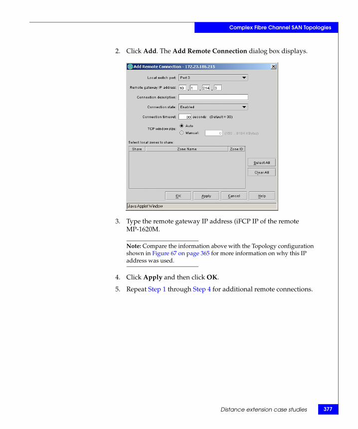
Complex Fibre Channel SAN Topologies
2. Click Add. The Add Remote Connection dialog box displays.
3. Type the remote gateway IP address (iFCP IP of the remote MP-1620M.
Note: Compare the information above with the Topology configuration shown in Figure 67 on page 365 for more information on why this IP address was used.
4. Click Apply and then click OK.
5. Repeat Step 1 through Step 4 for additional remote connections.
Distance extension case studies 377
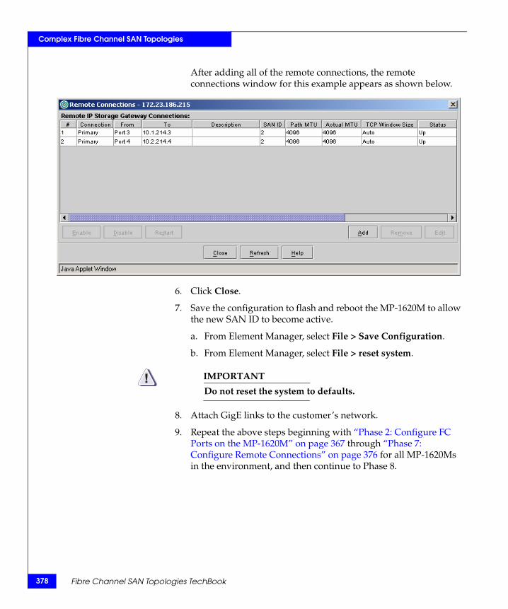
378
Complex Fibre Channel SAN Topologies
After adding all of the remote connections, the remote connections window for this example appears as shown below.
6. Click Close.
7. Save the configuration to flash and reboot the MP-1620M to allow the new SAN ID to become active.
a. From Element Manager, select File > Save Configuration.
b. From Element Manager, select File > reset system.
IMPORTANT!Do not reset the system to defaults.
8. Attach GigE links to the customer’s network.
9. Repeat the above steps beginning with “Phase 2: Configure FC Ports on the MP-1620M” on page 367 through “Phase 7: Configure Remote Connections” on page 376 for all MP-1620Ms in the environment, and then continue to Phase 8.
Fibre Channel SAN Topologies TechBook
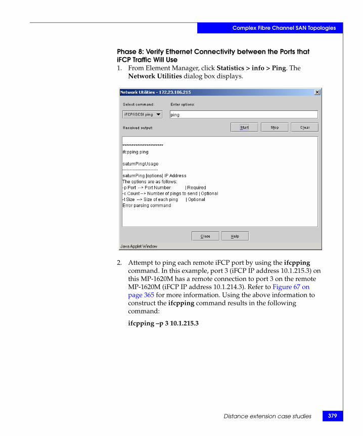
Complex Fibre Channel SAN Topologies
Phase 8: Verify Ethernet Connectivity between the Ports that iFCP Traffic Will Use1. From Element Manager, click Statistics > info > Ping. The
Network Utilities dialog box displays.
2. Attempt to ping each remote iFCP port by using the ifcpping command. In this example, port 3 (iFCP IP address 10.1.215.3) on this MP-1620M has a remote connection to port 3 on the remote MP-1620M (iFCP IP address 10.1.214.3). Refer to Figure 67 on page 365 for more information. Using the above information to construct the ifcpping command results in the following command:
ifcpping –p 3 10.1.215.3
Distance extension case studies 379
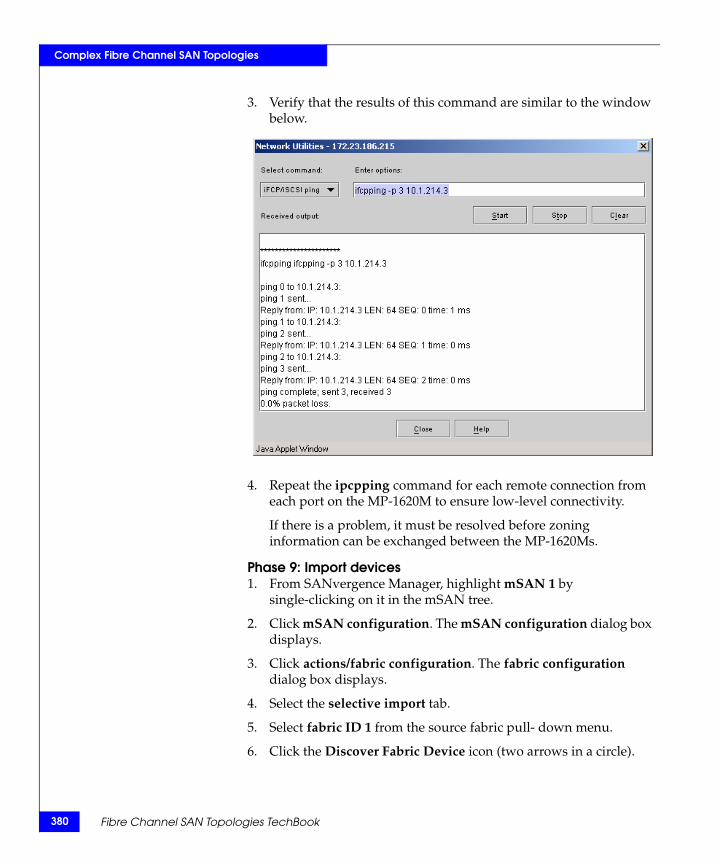
380
Complex Fibre Channel SAN Topologies
3. Verify that the results of this command are similar to the window below.
4. Repeat the ipcpping command for each remote connection from each port on the MP-1620M to ensure low-level connectivity.
If there is a problem, it must be resolved before zoning information can be exchanged between the MP-1620Ms.
Phase 9: Import devices1. From SANvergence Manager, highlight mSAN 1 by
single-clicking on it in the mSAN tree.
2. Click mSAN configuration. The mSAN configuration dialog box displays.
3. Click actions/fabric configuration. The fabric configuration dialog box displays.
4. Select the selective import tab.
5. Select fabric ID 1 from the source fabric pull- down menu.
6. Click the Discover Fabric Device icon (two arrows in a circle).
Fibre Channel SAN Topologies TechBook
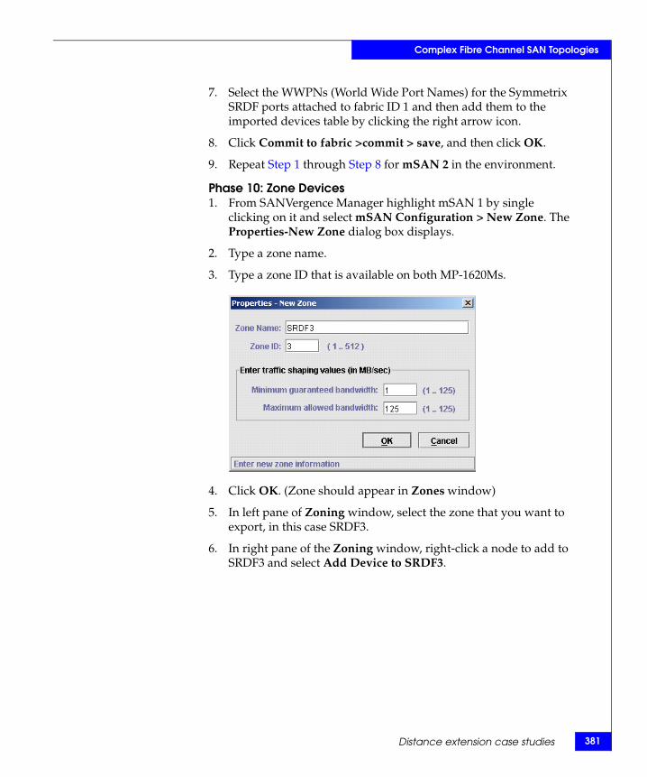
Complex Fibre Channel SAN Topologies
7. Select the WWPNs (World Wide Port Names) for the Symmetrix SRDF ports attached to fabric ID 1 and then add them to the imported devices table by clicking the right arrow icon.
8. Click Commit to fabric >commit > save, and then click OK.
9. Repeat Step 1 through Step 8 for mSAN 2 in the environment.
Phase 10: Zone Devices1. From SANVergence Manager highlight mSAN 1 by single
clicking on it and select mSAN Configuration > New Zone. The Properties-New Zone dialog box displays.
2. Type a zone name.
3. Type a zone ID that is available on both MP-1620Ms.
4. Click OK. (Zone should appear in Zones window)
5. In left pane of Zoning window, select the zone that you want to export, in this case SRDF3.
6. In right pane of the Zoning window, right-click a node to add to SRDF3 and select Add Device to SRDF3.
Distance extension case studies 381
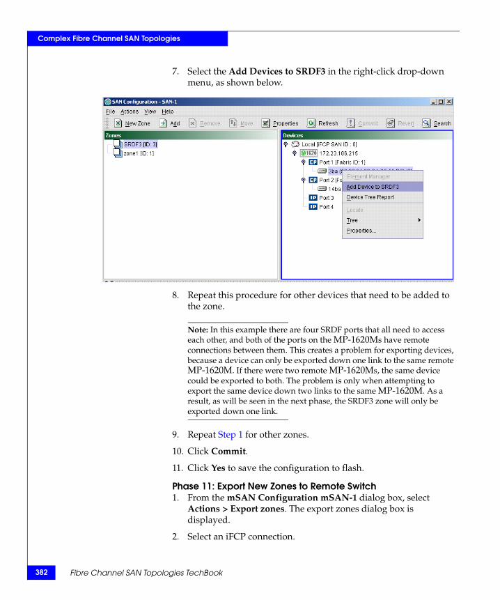
382
Complex Fibre Channel SAN Topologies
7. Select the Add Devices to SRDF3 in the right-click drop-down menu, as shown below.
8. Repeat this procedure for other devices that need to be added to the zone.
Note: In this example there are four SRDF ports that all need to access each other, and both of the ports on the MP-1620Ms have remote connections between them. This creates a problem for exporting devices, because a device can only be exported down one link to the same remote MP-1620M. If there were two remote MP-1620Ms, the same device could be exported to both. The problem is only when attempting to export the same device down two links to the same MP-1620M. As a result, as will be seen in the next phase, the SRDF3 zone will only be exported down one link.
9. Repeat Step 1 for other zones.
10. Click Commit.
11. Click Yes to save the configuration to flash.
Phase 11: Export New Zones to Remote Switch1. From the mSAN Configuration mSAN-1 dialog box, select
Actions > Export zones. The export zones dialog box is displayed.
2. Select an iFCP connection.
Fibre Channel SAN Topologies TechBook
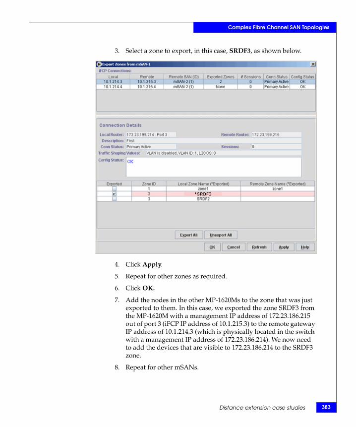
Complex Fibre Channel SAN Topologies
3. Select a zone to export, in this case, SRDF3, as shown below.
4. Click Apply.
5. Repeat for other zones as required.
6. Click OK.
7. Add the nodes in the other MP-1620Ms to the zone that was just exported to them. In this case, we exported the zone SRDF3 from the MP-1620M with a management IP address of 172.23.186.215 out of port 3 (iFCP IP address of 10.1.215.3) to the remote gateway IP address of 10.1.214.3 (which is physically located in the switch with a management IP address of 172.23.186.214). We now need to add the devices that are visible to 172.23.186.214 to the SRDF3 zone.
8. Repeat for other mSANs.
Distance extension case studies 383
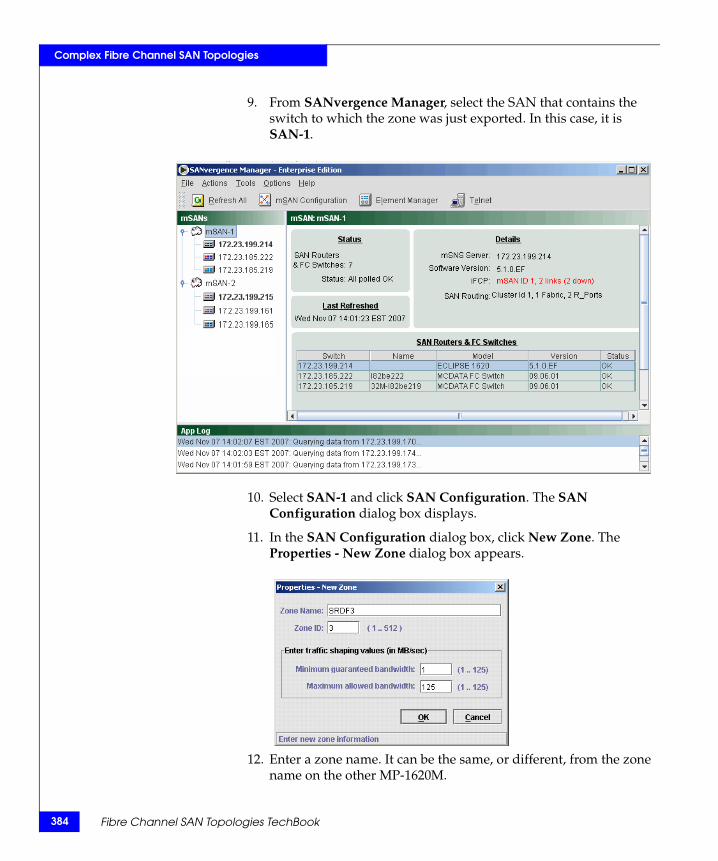
384
Complex Fibre Channel SAN Topologies
9. From SANvergence Manager, select the SAN that contains the switch to which the zone was just exported. In this case, it is SAN-1.
10. Select SAN-1 and click SAN Configuration. The SAN Configuration dialog box displays.
11. In the SAN Configuration dialog box, click New Zone. The Properties - New Zone dialog box appears.
12. Enter a zone name. It can be the same, or different, from the zone name on the other MP-1620M.
Fibre Channel SAN Topologies TechBook
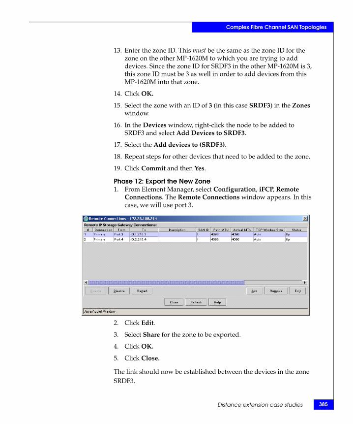
Complex Fibre Channel SAN Topologies
13. Enter the zone ID. This must be the same as the zone ID for the zone on the other MP-1620M to which you are trying to add devices. Since the zone ID for SRDF3 in the other MP-1620M is 3, this zone ID must be 3 as well in order to add devices from this MP-1620M into that zone.
14. Click OK.
15. Select the zone with an ID of 3 (in this case SRDF3) in the Zones window.
16. In the Devices window, right-click the node to be added to SRDF3 and select Add Devices to SRDF3.
17. Select the Add devices to (SRDF3).
18. Repeat steps for other devices that need to be added to the zone.
19. Click Commit and then Yes.
Phase 12: Export the New Zone1. From Element Manager, select Configuration, iFCP, Remote
Connections. The Remote Connections window appears. In this case, we will use port 3.
2. Click Edit.
3. Select Share for the zone to be exported.
4. Click OK.
5. Click Close.
The link should now be established between the devices in the zone SRDF3.
Distance extension case studies 385
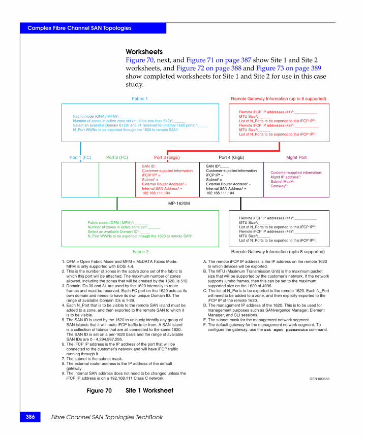
386
Complex Fibre Channel SAN Topologies
WorksheetsFigure 70, next, and Figure 71 on page 387 show Site 1 and Site 2 worksheets, and Figure 72 on page 388 and Figure 73 on page 389 show completed worksheets for Site 1 and Site 2 for use in this case study.
Figure 70 Site 1 Worksheet
Remote Gateway Information (up to 8 supported)
Mgmt PortPort 4 (GigE)Port 2 (FC)
Fabric 2 Remote Gateway Information (upto 8 supported)
GEN-000853
Fabric 1
MP-1620M
Port 1 (FC) Port 3 (GigE)
Remote iFCP IP addresses (#1)A:___________MTU SizeB:______List of N_Ports to be exported to this iFCP IPC:Remote iFCP IP addresses (#2)A:____________MTU SizeB:______List of N_Ports to be exported to this iFCP IPC:
Fabric mode (OFM / MFM)1:_______Number of zones in active zone set (must be less than 512)2:______Select an available Domain ID (30 and 31 reserved for internal 1620 ports)3:_____N_Port WWNs to be exported through the 1620 to remote SAN4:
SAN ID:Customer-supplied informationiFCIP IP6 =Subnet7 =External Router Address8 =Internal SAN Address9 =192.168.111.104
Customer-supplied information:Mgmt IP addressD:Subnet MaskE:GatewayF:
Fabric mode (OFM / MFM)1:_______Number of zones in active zone set2:______Select an available Domain ID3:_____N_Port WWNs to be exported through the 1620 to remote SAN4:
1. OFM = Open Fabric Mode and MFM = McDATA Fabric Mode. MFM is only supported with EOSi 4.4.2. This is the number of zones in the active zone set of the fabric to which this port will be attached. The maximum number of zones allowed, including the zones that will be created by the 1620, is 512.3. Domain IDs 30 and 31 are used by the 1620 internally to route frames and must be reserved. Each FC port on the 1620 acts as its own domain and needs to have its own unique Domain ID. The range of available Domain IDs is 1-29.4. Each N_Port that is to be visible to the remote SAN island must be added to a zone, and then exported to the remote SAN to which it is to be visible.5. The SAN ID is used by the 1620 to uniquely identify any group of SAN islands that it will route iFCP traffic to or from. A SAN island is a collection of fabrics that are all connected to the same 1620. The SAN ID is set on a per-1620 basis and the range of available SAN IDs are 0 - 4,294,967,295.6. The iFCP IP address is the IP address of the port that will be connected to the customer’s network and will have iFCP traffic running through it.7. The subnet is the subnet mask.8. The external router address is the IP address of the default gateway.9. The internal SAN address does not need to be changed unless the iFCP IP address is on a 192.168.111 Class C network.
A. The remote iFCP IP address is the IP address on the remote 1620 to which devices will be exported.B. The MTU (Maximum Transmission Unit) is the maximum packet size that will be supported by the customer’s network. If the network supports jumbo frames, then this can be set to the maximum supported size on the 1620 of 4096.C. The list of N_Ports to be exported to the remote 1620. Each N_Port will need to be added to a zone, and then explicity exported to the iFCP IP of the remote 1620.D. The management IP address of the 1620. This is to be used for management purposes such as SANvergence Manager, Element Manager, and CLI sessions.E. The subnet mask for the management network segment.F. The default gateway for the management network segment. To configure the gateway, use the set mgmt permroute command.
SAN ID5:____Customer-supplied informationiFCP IP6 =Subnet7 =External Router Address8 =Internal SAN Address9 =192.168.111.104
Remote iFCP IP addresses (#1)A:___________MTU SizeB:______List of N_Ports to be exported to this iFCP IPC:Remote iFCP IP addresses (#2)A:____________MTU SizeB:______List of N_Ports to be exported to this iFCP IPC:
Fibre Channel SAN Topologies TechBook
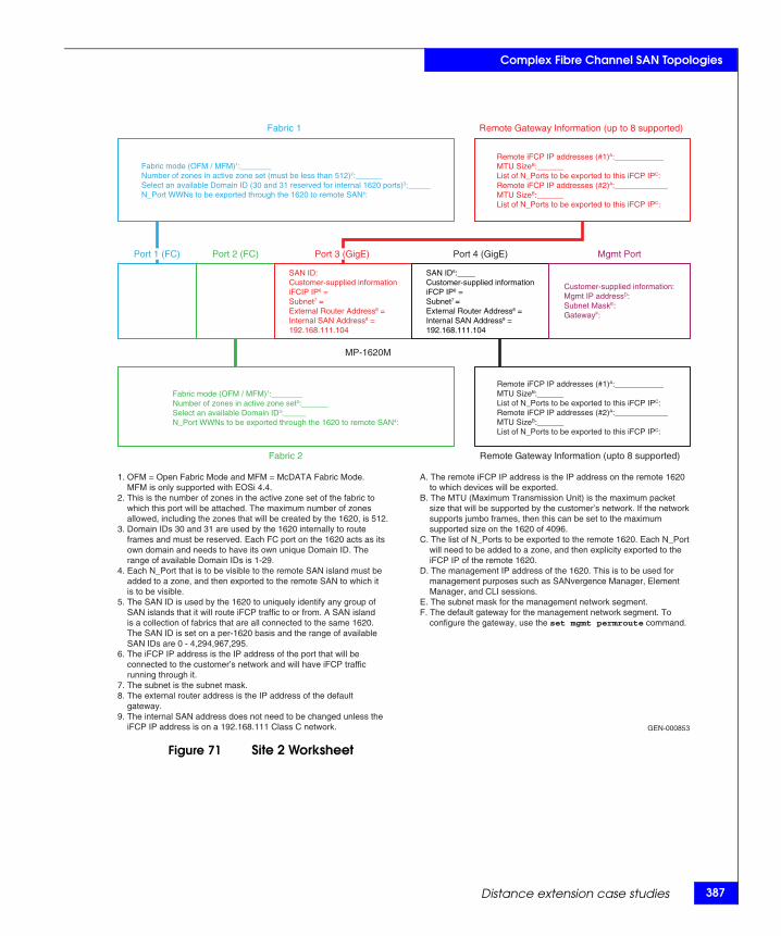
Complex Fibre Channel SAN Topologies
Figure 71 Site 2 Worksheet
Remote Gateway Information (up to 8 supported)
Mgmt PortPort 4 (GigE)Port 2 (FC)
Fabric 2 Remote Gateway Information (upto 8 supported)
GEN-000853
Fabric 1
MP-1620M
Port 1 (FC) Port 3 (GigE)
Remote iFCP IP addresses (#1)A:___________MTU SizeB:______List of N_Ports to be exported to this iFCP IPC:Remote iFCP IP addresses (#2)A:____________MTU SizeB:______List of N_Ports to be exported to this iFCP IPC:
Fabric mode (OFM / MFM)1:_______Number of zones in active zone set (must be less than 512)2:______Select an available Domain ID (30 and 31 reserved for internal 1620 ports)3:_____N_Port WWNs to be exported through the 1620 to remote SAN4:
SAN ID:Customer-supplied informationiFCIP IP6 =Subnet7 =External Router Address8 =Internal SAN Address9 =192.168.111.104
Customer-supplied information:Mgmt IP addressD:Subnet MaskE:GatewayF:
Fabric mode (OFM / MFM)1:_______Number of zones in active zone set2:______Select an available Domain ID3:_____N_Port WWNs to be exported through the 1620 to remote SAN4:
1. OFM = Open Fabric Mode and MFM = McDATA Fabric Mode. MFM is only supported with EOSi 4.4.2. This is the number of zones in the active zone set of the fabric to which this port will be attached. The maximum number of zones allowed, including the zones that will be created by the 1620, is 512.3. Domain IDs 30 and 31 are used by the 1620 internally to route frames and must be reserved. Each FC port on the 1620 acts as its own domain and needs to have its own unique Domain ID. The range of available Domain IDs is 1-29.4. Each N_Port that is to be visible to the remote SAN island must be added to a zone, and then exported to the remote SAN to which it is to be visible.5. The SAN ID is used by the 1620 to uniquely identify any group of SAN islands that it will route iFCP traffic to or from. A SAN island is a collection of fabrics that are all connected to the same 1620. The SAN ID is set on a per-1620 basis and the range of available SAN IDs are 0 - 4,294,967,295.6. The iFCP IP address is the IP address of the port that will be connected to the customer’s network and will have iFCP traffic running through it.7. The subnet is the subnet mask.8. The external router address is the IP address of the default gateway.9. The internal SAN address does not need to be changed unless the iFCP IP address is on a 192.168.111 Class C network.
A. The remote iFCP IP address is the IP address on the remote 1620 to which devices will be exported.B. The MTU (Maximum Transmission Unit) is the maximum packet size that will be supported by the customer’s network. If the network supports jumbo frames, then this can be set to the maximum supported size on the 1620 of 4096.C. The list of N_Ports to be exported to the remote 1620. Each N_Port will need to be added to a zone, and then explicity exported to the iFCP IP of the remote 1620.D. The management IP address of the 1620. This is to be used for management purposes such as SANvergence Manager, Element Manager, and CLI sessions.E. The subnet mask for the management network segment.F. The default gateway for the management network segment. To configure the gateway, use the set mgmt permroute command.
SAN ID5:____Customer-supplied informationiFCP IP6 =Subnet7 =External Router Address8 =Internal SAN Address9 =192.168.111.104
Remote iFCP IP addresses (#1)A:___________MTU SizeB:______List of N_Ports to be exported to this iFCP IPC:Remote iFCP IP addresses (#2)A:____________MTU SizeB:______List of N_Ports to be exported to this iFCP IPC:
Distance extension case studies 387
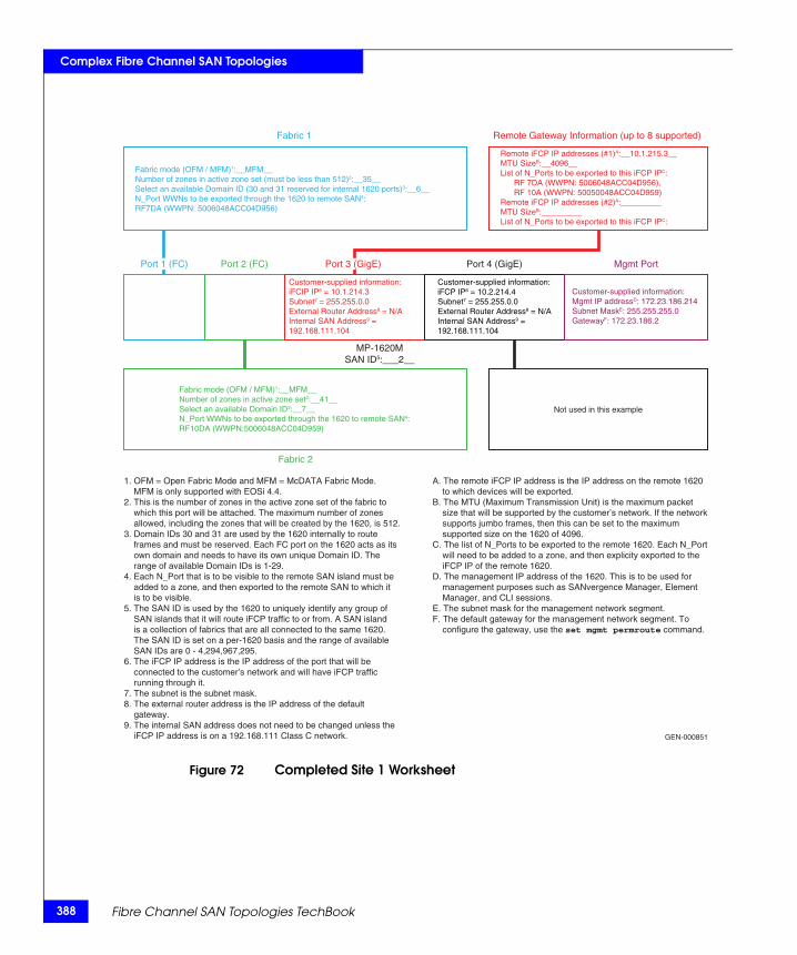
388
Complex Fibre Channel SAN Topologies
Figure 72 Completed Site 1 Worksheet
Remote Gateway Information (up to 8 supported)
Mgmt PortPort 4 (GigE)Port 2 (FC)
Fabric 2
GEN-000851
Fabric 1
MP-1620MSAN ID5:___2__
Port 1 (FC) Port 3 (GigE)
Remote iFCP IP addresses (#1)A:__10.1.215.3__MTU SizeB:__4096__List of N_Ports to be exported to this iFCP IPC: RF 7DA (WWPN: 5006048ACC04D956), RF 10A (WWPN: 50050048ACC04D959)Remote iFCP IP addresses (#2)A:_________MTU SizeB:_________List of N_Ports to be exported to this iFCP IPC:
Fabric mode (OFM / MFM)1:__MFM__Number of zones in active zone set (must be less than 512)2:__35__Select an available Domain ID (30 and 31 reserved for internal 1620 ports)3:__6__N_Port WWNs to be exported through the 1620 to remote SAN4:RF7DA (WWPN: 5006048ACC04D956)
Customer-supplied information:iFCIP IP6 = 10.1.214.3Subnet7 = 255.255.0.0External Router Address8 = N/AInternal SAN Address9 =192.168.111.104
Not used in this example
Customer-supplied information:Mgmt IP addressD: 172.23.186.214Subnet MaskE: 255.255.255.0GatewayF: 172.23.186.2
Fabric mode (OFM / MFM)1:__MFM__Number of zones in active zone set2:__41__Select an available Domain ID3:__7__N_Port WWNs to be exported through the 1620 to remote SAN4:RF10DA (WWPN:5006048ACC04D959)
1. OFM = Open Fabric Mode and MFM = McDATA Fabric Mode. MFM is only supported with EOSi 4.4.2. This is the number of zones in the active zone set of the fabric to which this port will be attached. The maximum number of zones allowed, including the zones that will be created by the 1620, is 512.3. Domain IDs 30 and 31 are used by the 1620 internally to route frames and must be reserved. Each FC port on the 1620 acts as its own domain and needs to have its own unique Domain ID. The range of available Domain IDs is 1-29.4. Each N_Port that is to be visible to the remote SAN island must be added to a zone, and then exported to the remote SAN to which it is to be visible.5. The SAN ID is used by the 1620 to uniquely identify any group of SAN islands that it will route iFCP traffic to or from. A SAN island is a collection of fabrics that are all connected to the same 1620. The SAN ID is set on a per-1620 basis and the range of available SAN IDs are 0 - 4,294,967,295.6. The iFCP IP address is the IP address of the port that will be connected to the customer’s network and will have iFCP traffic running through it.7. The subnet is the subnet mask.8. The external router address is the IP address of the default gateway.9. The internal SAN address does not need to be changed unless the iFCP IP address is on a 192.168.111 Class C network.
A. The remote iFCP IP address is the IP address on the remote 1620 to which devices will be exported.B. The MTU (Maximum Transmission Unit) is the maximum packet size that will be supported by the customer’s network. If the network supports jumbo frames, then this can be set to the maximum supported size on the 1620 of 4096.C. The list of N_Ports to be exported to the remote 1620. Each N_Port will need to be added to a zone, and then explicity exported to the iFCP IP of the remote 1620.D. The management IP address of the 1620. This is to be used for management purposes such as SANvergence Manager, Element Manager, and CLI sessions.E. The subnet mask for the management network segment.F. The default gateway for the management network segment. To configure the gateway, use the set mgmt permroute command.
Customer-supplied information:iFCP IP6 = 10.2.214.4Subnet7 = 255.255.0.0External Router Address8 = N/AInternal SAN Address9 =192.168.111.104
Fibre Channel SAN Topologies TechBook
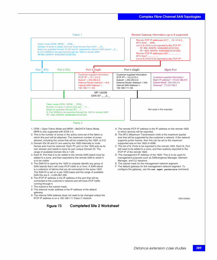
Complex Fibre Channel SAN Topologies
Figure 73 Completed Site 2 Worksheet
Remote Gateway Information (up to 8 supported)
Mgmt PortPort 4 (GigE)Port 2 (FC)
Fabric 2
GEN-000852
Fabric 1
MP-1620MSAN ID5:___2__
Port 1 (FC) Port 3 (GigE)
Remote iFCP IP addresses (#1)A:__10.1.214.3__MTU SizeB:__4096__List of N_Ports to be exported to this iFCP IPC: RF 3BA (WWPN: 50060482C4C551D2) RF 14BA (WWPN: 50060482C4C551DD)Remote iFCP IP addresses (#2)A:_________MTU SizeB:_________List of N_Ports to be exported to this iFCP IPC:
Fabric mode (OFM / MFM)1:__OFM__Number of zones in active zone set (must be less than 512)2:__16__Select an available Domain ID (30 and 31 reserved for internal 1620 ports)3:__6__N_Port WWNs to be exported through the 1620 to remote SAN4:RF3BA (WWPN: 50060482C4C551D2)
Customer-supplied information:iFCIP IP6 = 10.1.215.3Subnet7 = 255.255.0.0External Router Address8 = N/AInternal SAN Address9 =192.168.111.104
Not used in this example
Customer-supplied information:Mgmt IP addressD: 172.23.186.215Subnet MaskE: 255.255.0.0GatewayF: 172.23.186.2
Fabric mode (OFM / MFM)1:__OFM__Number of zones in active zone set2:__11__Select an available Domain ID3:__7__N_Port WWNs to be exported through the 1620 to remote SAN4:RF 14BA (WWPN: 50060482C4C551DD)
1. OFM = Open Fabric Mode and MFM = McDATA Fabric Mode. MFM is only supported with EOSi 4.4.2. This is the number of zones in the active zone set of the fabric to which this port will be attached. The maximum number of zones allowed, including the zones that will be created by the 1620, is 512.3. Domain IDs 30 and 31 are used by the 1620 internally to route frames and must be reserved. Each FC port on the 1620 acts as its own domain and needs to have its own unique Domain ID. The range of available Domain IDs is 1-29.4. Each N_Port that is to be visible to the remote SAN island must be added to a zone, and then exported to the remote SAN to which it is to be visible.5. The SAN ID is used by the 1620 to uniquely identify any group of SAN islands that it will route iFCP traffic to or from. A SAN island is a collection of fabrics that are all connected to the same 1620. The SAN ID is set on a per-1620 basis and the range of available SAN IDs are 0 - 4,294,967,295.6. The iFCP IP address is the IP address of the port that will be connected to the customer’s network and will have iFCP traffic running through it.7. The subnet is the subnet mask.8. The external router address is the IP address of the default gateway.9. The internal SAN address does not need to be changed unless the iFCP IP address is on a 192.168.111 Class C network.
A. The remote iFCP IP address is the IP address on the remote 1620 to which devices will be exported.B. The MTU (Maximum Transmission Unit) is the maximum packet size that will be supported by the customer’s network. If the network supports jumbo frames, then this can be set to the maximum supported size on the 1620 of 4096.C. The list of N_Ports to be exported to the remote 1620. Each N_Port will need to be added to a zone, and then explicity exported to the iFCP IP of the remote 1620.D. The management IP address of the 1620. This is to be used for management purposes such as SANvergence Manager, Element Manager, and CLI sessions.E. The subnet mask for the management network segment.F. The default gateway for the management network segment. To configure the gateway, use the set mgmt permroute command.
Customer-supplied information:iFCP IP6 = 10.2.215.4Subnet7 = 255.255.0.0External Router Address8 = N/AInternal SAN Address9 =192.168.111.104
Distance extension case studies 389
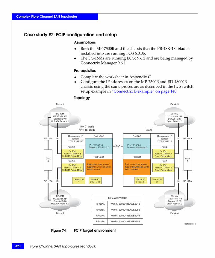
390
Complex Fibre Channel SAN Topologies
Case study #2: FCIP configuration and setup
Assumptions
◆ Both the MP-7500B and the chassis that the PB-48K-18i blade is installed into are running FOS 6.0.0b.
◆ The DS-16Ms are running EOSc 9.6.2 and are being managed by Connectrix Manager 9.6.1
Prerequisites
◆ Complete the worksheet in Appendix C◆ Configure the IP addresses on the MP-7500B and ED-48000B
chassis using the same procedure as described in the two switch setup example in “Connectrix B example” on page 140.
Topology
Figure 74 FCIP Target environment
Port 1/Ge0
48k ChassisFR4-18i blade 7500
Port 1/Ge1
Management IPaddress
172.23.186.207
Port Ge0
Port Ge1
Management IPaddress
172.23.186.215
DS-16M172.23.186.155Domain ID 29
Open Fabric 1.0
DS-16M172.23.186.153Domain ID 27
Open Fabric 1.0
ISL RF 12AA
ISL RF 12BA
DMXB
ISLRF 12AA
ISLRF 12BA
DMXA
Fabric 3
Fabric 4
GEN-000814
Fabric 1
Fabric 2
DS-16M172.23.186.152Domain ID 10
McDATA Fabric 1.0
DS-16M172.23.186.154Domain ID 28
McDATA Fabric 1.0
GigEIP = 10.1.214.5Subnet = 255.255.0.0
Redundant links are notsupported with Fast Writein this release
Port 1/4
Port 1/5
IP = 10.1.215.5Subnet = 255.255.0.0
Redundant links are notsupported with Fast Writein this release
Port 2
Port 1
Ex_PortFabric ID (FID) = 8
McDATA Fabric Mode
Fabric ID(FID) = 64
Domain ID1
Fabric ID(FID) = 64
Domain ID2
Ex_PortFabric ID (FID) = 9
McDATA Fabric Mode
Ex_PortFabric ID (FID) = 4Open Fabric Mode
Ex_PortFabric ID (FID) = 5Open Fabric Mode
WWPN 50060482D52E694B
FA to WWPN table
RF12AA
WWPN 50060482D52E695BRF12BA
WWPN 50060482E22E694BRF12AA
WWPN 50060482E22E695BRF12BA
Fibre Channel SAN Topologies TechBook

Complex Fibre Channel SAN Topologies
Phase 1: Configure the Backbone Fabric ID1. From within a telnet session to the MP-7500B with an
Management IP address of 172.23.186.207, enter the following commands.
• Use fosconfig –disable fcr to disable the Fibre Channel Routing Service (note the – before the disable is a double dash).
• Use fcrconfigure to change the Backbone Fabric ID to the have the appropriate value, 64 in this example.
• Use fosconfig –enable fcr to enable the Fibre Channel Routing Service (note the – before the disable is a double dash).
Phase 2: Configure the Ex_Ports1. Use the portcfgexport 1/4 –a 1 –f 8 –m 2 –t 1 command to
configure port 1/4. The options used are described as follows:
• 1/4 – The interface being configured in slot/port format.
• -a 1 – Enables the port as an Ex_Port.
• -f 8 – The Fabric ID of the Ex_Port. All Ex_Ports that are connected to the same fabric must have the same Fabric ID. All Ex_Ports that have the same Fabric ID must be connected to the same Fabric.
• -m 2 – The interop mode the Ex_Port should use to connect to the external Fabric. In this case, -m 1 means use McDATA Fabric Mode.
• -t 1 – Enables the negotiation of fabric parameters.
2. Persistently enable port 1/4 using the portcfgpersistentenable 1/4 command.
3. Use the portcfgexport 1/5 –a 1 –f 9 –m 2 –t 1 command to configure port 1/5. The options used are described as follows:
• 1/5 – The interface being configured in slot/port format.
• -a 1 – Enables the port as an Ex_Port.
• -f 9 – The Fabric ID of the Ex_Port. All Ex_Ports that are connected to the same fabric must have the same Fabric ID. All Ex_Ports that have the same Fabric ID must be connected to the same Fabric.
• -m 2 – The interop mode the Ex_Port should use to connect to the external Fabric. In this case, -m 1 means use McDATA Fabric Mode.
Distance extension case studies 391
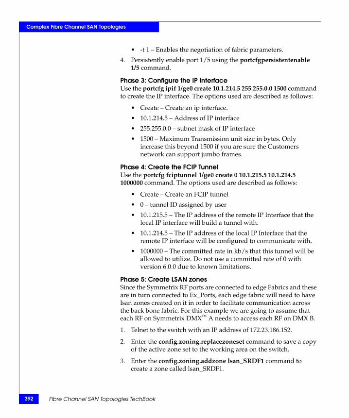
392
Complex Fibre Channel SAN Topologies
• -t 1 – Enables the negotiation of fabric parameters.
4. Persistently enable port 1/5 using the portcfgpersistentenable 1/5 command.
Phase 3: Configure the IP InterfaceUse the portcfg ipif 1/ge0 create 10.1.214.5 255.255.0.0 1500 command to create the IP interface. The options used are described as follows:
• Create – Create an ip interface.
• 10.1.214.5 – Address of IP interface
• 255.255.0.0 – subnet mask of IP interface
• 1500 – Maximum Transmission unit size in bytes. Only increase this beyond 1500 if you are sure the Customers network can support jumbo frames.
Phase 4: Create the FCIP TunnelUse the portcfg fciptunnel 1/ge0 create 0 10.1.215.5 10.1.214.5 1000000 command. The options used are described as follows:
• Create – Create an FCIP tunnel
• 0 – tunnel ID assigned by user
• 10.1.215.5 – The IP address of the remote IP Interface that the local IP interface will build a tunnel with.
• 10.1.214.5 – The IP address of the local IP Interface that the remote IP interface will be configured to communicate with.
• 1000000 – The committed rate in kb/s that this tunnel will be allowed to utilize. Do not use a committed rate of 0 with version 6.0.0 due to known limitations.
Phase 5: Create LSAN zonesSince the Symmetrix RF ports are connected to edge Fabrics and these are in turn connected to Ex_Ports, each edge fabric will need to have lsan zones created on it in order to facilitate communication across the back bone fabric. For this example we are going to assume that each RF on Symmetrix DMX™ A needs to access each RF on DMX B.
1. Telnet to the switch with an IP address of 172.23.186.152.
2. Enter the config.zoning.replacezoneset command to save a copy of the active zone set to the working area on the switch.
3. Enter the config.zoning.addzone lsan_SRDF1 command to create a zone called lsan_SRDF1.
Fibre Channel SAN Topologies TechBook
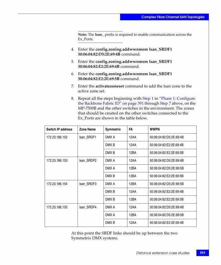
Complex Fibre Channel SAN Topologies
Note: The lsan_ prefix is required to enable communication across the Ex_Ports.
4. Enter the config.zoning.addwwnmem lsan_SRDF1 50:06:04:82:D5:2E:69:4B command.
5. Enter the config.zoning.addwwnmem lsan_SRDF1 50:06:04:82:E2:2E:69:4B command.
6. Enter the config.zoning.addwwnmem lsan_SRDF1 50:06:04:82:E2:2E:69:5B command.
7. Enter the activatezoneset command to add the lsan zone to the active zone set.
8. Repeat all the steps beginning with Step 1 in “Phase 1: Configure the Backbone Fabric ID” on page 391 through Step 7 above, on the MP-7500B and the other switches in the environment. The zones that should be created on the other switches connected to the Ex_Ports are shown in the table below.
At this point the SRDF links should be up between the two Symmetrix DMX systems.
Switch IP address Zone Name Symmetrix FA WWPN
172.23.186.152 lsan_SRDF1 DMX A 12AA 50:06:04:82:D5:2E:69:4B
DMX B 12AA 50:06:04:82:E2:2E:69:4B
DMX B 12BA 50:06:04:82:E2:2E:69:5B
172.23.186.153 lsan_SRDF2 DMX A 12AA 50:06:04:82:D5:2E:69:4B
DMX A 12BA 50:06:04:82:D5:2E:69:5B
DMX B 12BA 50:06:04:82:E2:2E:69:5B
172.23.186.154 lsan_SRDF3 DMX A 12BA 50:06:04:82:D5:2E:69:5B
DMX B 12AA 50:06:04:82:E2:2E:69:4B
DMX B 12BA 50:06:04:82:E2:2E:69:5B
172.23.186.155 lsan_SRDF4 DMX A 12AA 50:06:04:82:D5:2E:69:4B
DMX A 12BA 50:06:04:82:D5:2E:69:5B
DMX B 12AA 50:06:04:82:E2:2E:69:4B
Distance extension case studies 393
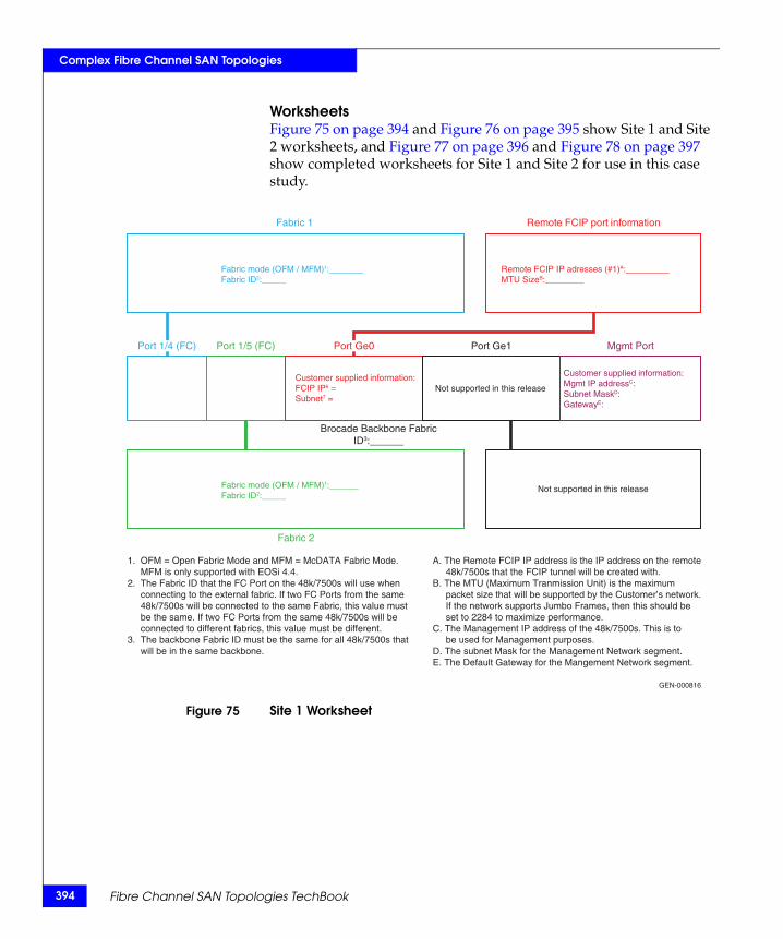
394
Complex Fibre Channel SAN Topologies
WorksheetsFigure 75 on page 394 and Figure 76 on page 395 show Site 1 and Site 2 worksheets, and Figure 77 on page 396 and Figure 78 on page 397 show completed worksheets for Site 1 and Site 2 for use in this case study.
Figure 75 Site 1 Worksheet
Remote FCIP port information
Mgmt PortPort Ge1Port 1/5 (FC)
Fabric 2
1. OFM = Open Fabric Mode and MFM = McDATA Fabric Mode. MFM is only supported with EOSi 4.4.2. The Fabric ID that the FC Port on the 48k/7500s will use when connecting to the external fabric. If two FC Ports from the same 48k/7500s will be connected to the same Fabric, this value must be the same. If two FC Ports from the same 48k/7500s will be connected to different fabrics, this value must be different.3. The backbone Fabric ID must be the same for all 48k/7500s that will be in the same backbone.
A. The Remote FCIP IP address is the IP address on the remote 48k/7500s that the FCIP tunnel will be created with. B. The MTU (Maximum Tranmission Unit) is the maximum packet size that will be supported by the Customer’s network. If the network supports Jumbo Frames, then this should be set to 2284 to maximize performance.C. The Management IP address of the 48k/7500s. This is to be used for Management purposes.D. The subnet Mask for the Management Network segment.E. The Default Gateway for the Mangement Network segment.
GEN-000816
Fabric 1
Brocade Backbone FabricID3:______
Port 1/4 (FC) Port Ge0
Remote FCIP IP adresses (#1)A:_________MTU SizeB:________
Fabric mode (OFM / MFM)1:_______Fabric ID2:_____
Customer supplied information:FCIP IP6 = Subnet7 =
Fabric mode (OFM / MFM)1:______Fabric ID2:_____
Not supported in this release
Not supported in this release
Customer supplied information:Mgmt IP addressC: Subnet MaskD: GatewayE:
Fibre Channel SAN Topologies TechBook
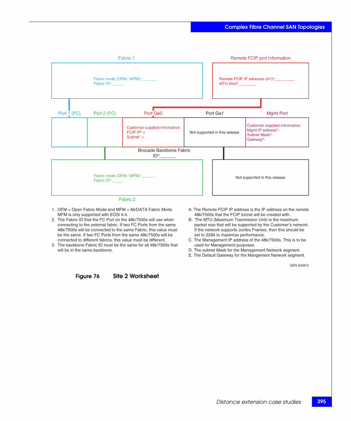
Complex Fibre Channel SAN Topologies
Figure 76 Site 2 Worksheet
Remote FCIP port information
Mgmt PortPort Ge1Port 2 (FC)
Fabric 2
1. OFM = Open Fabric Mode and MFM = McDATA Fabric Mode. MFM is only supported with EOSi 4.4.2. The Fabric ID that the FC Port on the 48k/7500s will use when connecting to the external fabric. If two FC Ports from the same 48k/7500s will be connected to the same Fabric, this value must be the same. If two FC Ports from the same 48k/7500s will be connected to different fabrics, this value must be different.3. The backbone Fabric ID must be the same for all 48k/7500s that will be in the same backbone.
A. The Remote FCIP IP address is the IP address on the remote 48k/7500s that the FCIP tunnel will be created with. B. The MTU (Maximum Tranmission Unit) is the maximum packet size that will be supported by the Customer’s network. If the network supports Jumbo Frames, then this should be set to 2284 to maximize performance.C. The Management IP address of the 48k/7500s. This is to be used for Management purposes.D. The subnet Mask for the Management Network segment.E. The Default Gateway for the Mangement Network segment.
GEN-000815
Fabric 1
Brocade Backbone FabricID3:______
Port 1 (FC) Port Ge0
Remote FCIP IP adresses (#1)A:_________MTU SizeB:________
Fabric mode (OFM / MFM)1:_______Fabric ID2:_____
Customer supplied information:FCIP IP6 = Subnet7 =
Fabric mode (OFM / MFM)1:______Fabric ID2:_____
Not supported in this release
Not supported in this release
Customer supplied information:Mgmt IP addressC: Subnet MaskD: GatewayE:
Distance extension case studies 395
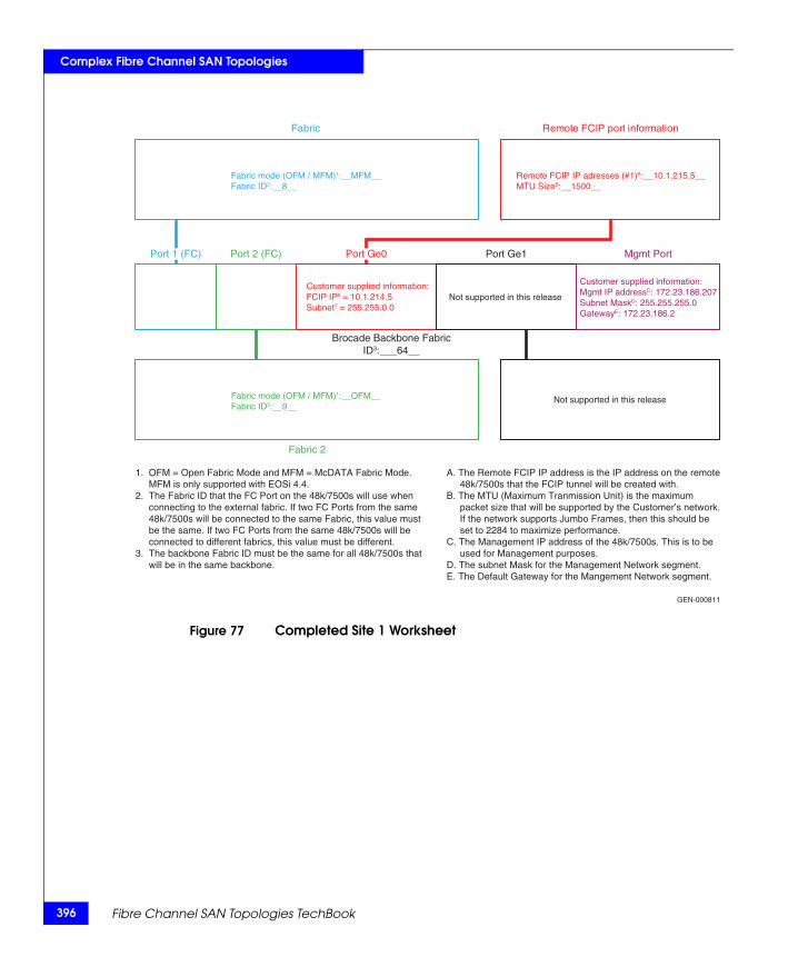
396
Complex Fibre Channel SAN Topologies
Figure 77 Completed Site 1 Worksheet
Remote FCIP port information
Mgmt PortPort Ge1Port 2 (FC)
Fabric 2
1. OFM = Open Fabric Mode and MFM = McDATA Fabric Mode. MFM is only supported with EOSi 4.4.2. The Fabric ID that the FC Port on the 48k/7500s will use when connecting to the external fabric. If two FC Ports from the same 48k/7500s will be connected to the same Fabric, this value must be the same. If two FC Ports from the same 48k/7500s will be connected to different fabrics, this value must be different.3. The backbone Fabric ID must be the same for all 48k/7500s that will be in the same backbone.
A. The Remote FCIP IP address is the IP address on the remote 48k/7500s that the FCIP tunnel will be created with. B. The MTU (Maximum Tranmission Unit) is the maximum packet size that will be supported by the Customer’s network. If the network supports Jumbo Frames, then this should be set to 2284 to maximize performance.C. The Management IP address of the 48k/7500s. This is to be used for Management purposes.D. The subnet Mask for the Management Network segment.E. The Default Gateway for the Mangement Network segment.
GEN-000811
Fabric
Brocade Backbone FabricID3:___64__
Port 1 (FC) Port Ge0
Remote FCIP IP adresses (#1)A:__10.1.215.5__MTU SizeB:__1500__
Fabric mode (OFM / MFM)1:__MFM__Fabric ID2:__8__
Customer supplied information:FCIP IP6 = 10.1.214.5Subnet7 = 255.255.0.0
Fabric mode (OFM / MFM)1:__OFM__Fabric ID2:__9__
Not supported in this release
Not supported in this release
Customer supplied information:Mgmt IP addressC: 172.23.186.207Subnet MaskD: 255.255.255.0GatewayE: 172.23.186.2
Fibre Channel SAN Topologies TechBook
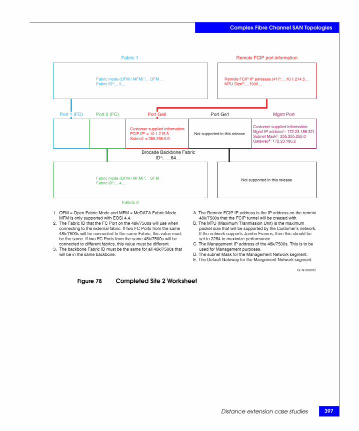
Complex Fibre Channel SAN Topologies
Figure 78 Completed Site 2 Worksheet
Remote FCIP port information
Mgmt PortPort Ge1Port 2 (FC)
Fabric 2
1. OFM = Open Fabric Mode and MFM = McDATA Fabric Mode. MFM is only supported with EOSi 4.4.2. The Fabric ID that the FC Port on the 48k/7500s will use when connecting to the external fabric. If two FC Ports from the same 48k/7500s will be connected to the same Fabric, this value must be the same. If two FC Ports from the same 48k/7500s will be connected to different fabrics, this value must be different.3. The backbone Fabric ID must be the same for all 48k/7500s that will be in the same backbone.
A. The Remote FCIP IP address is the IP address on the remote 48k/7500s that the FCIP tunnel will be created with. B. The MTU (Maximum Tranmission Unit) is the maximum packet size that will be supported by the Customer’s network. If the network supports Jumbo Frames, then this should be set to 2284 to maximize performance.C. The Management IP address of the 48k/7500s. This is to be used for Management purposes.D. The subnet Mask for the Management Network segment.E. The Default Gateway for the Mangement Network segment.
GEN-000812
Fabric 1
Brocade Backbone FabricID3:___64__
Port 1 (FC) Port Ge0
Remote FCIP IP adresses (#1)A:__10.1.214.5__MTU SizeB:__1500__
Fabric mode (OFM / MFM)1:__OFM__Fabric ID2:__5__
Customer supplied information:FCIP IP6 = 10.1.215.5Subnet7 = 255.255.0.0
Fabric mode (OFM / MFM)1:__OFM__Fabric ID2:__4__
Not supported in this release
Not supported in this release
Customer supplied information:Mgmt IP addressC: 172.23.186.221Subnet MaskD: 255.255.255.0GatewayE: 172.23.186.2
Distance extension case studies 397

398
Complex Fibre Channel SAN Topologies
Fibre Channel SAN Topologies TechBook
4
This chapter provides the following information to monitor your SAN to limit errors that can impact performance:
◆ Introduction ...................................................................................... 400◆ Switch-based error types................................................................. 402◆ Fabric resiliency features and recommendations ........................ 408◆ Brocade fabric resiliency concepts ................................................. 416◆ Configuring FS features case study............................................... 423◆ Summary ........................................................................................... 438
Monitoring your SAN
Monitoring your SAN 399
400
Monitoring your SAN
IntroductionAs storage needs continue to grow, SANs are not only expanding in size, but are also becoming more complex and more application- intensive. Over the years, high density, high accessibility, and high scalability have been the quality aspects associated with SANs. So, do the same best practices used for designing your SAN still apply for these large and complex SANs?
The answer is yes. However, while reliability of data and prevention of outages have always been a priority when it comes to designing and administering a SAN, performance is also a critical factor to take into consideration. With the advent of newer technologies (such as installation of SSDs and deployment of FAST VP), not only are data response times expected to get shorter, but there is bound to be an increase in IOPS. This can have an impact on the available bandwidth and could become a potential source of congestion if the SAN is not well-designed and monitored. Just as proper SAN administering and design are considered best practices to manage your SAN, proper SAN monitoring should not be neglected. This chapter will detail recommended best practices to monitor your SAN to ensure higher performance.
Effective SAN monitoring not only assists in detecting any existing error conditions in a SAN, but also makes performance adjustments and aids in decisions for future capacity planning.
This chapter provides recommended best practices for monitoring your SAN. These best practices are essential for large and complex SANs that manage critical data and have optimal performance requirements.
Some of the fabric resiliency-based SAN monitoring features that will be reviewed have been added in the newer switch firmware versions and are meant to assist users in detecting high latency and congestion scenarios to prevent fabric-wide impact in a SAN. It is important to note that these features do not eliminate these error conditions.
Note: To better understand the concept of congestion, refer to the "Congestion and backpressure " section in the "FC SAN Concepts" chapter of the Networked Storage Concepts and Protocols TechBook, available on the E-Lab Navigator, Topology Resource Center tab.
Fibre Channel SAN Topologies TechBook

Monitoring your SAN
This chapter first discusses different switch error types, how they originate in a SAN, and how they can be detected in a Brocade or Connectrix-B switch fabric. Next, current firmware features that can be used to detect the different types of switch errors, along with recommendations to prevent error impact on other switch components and device functionality in the SAN, are offered. A case study shows how a user or SAN administrator can configure these fabric resiliency features on a switch.
Introduction 401
402
Monitoring your SAN
Switch-based error typesBefore reviewing the fabric resiliency features available on FC switches today, it is important to examine the different kind of switch-based errors, how they originate in a SAN, and how they can be monitored using the switch command line interface (CLI). This section provides different types of errors, pausible causes, and error displays.
Error type Invalid Cyclic Redundancy Checks (CRC), or frame errorsCRC errors indicate framing or bit errors that can occur on any link with media or transmission problems. The following are some specific areas within the FC frame that can cause a CRC error:
◆ Bad or missing SOF/EOF values
These errors cover frames with SOF/EOF that have invalid delimiter values. (For more information on standard delimiter values, refer to the "Ordered sets" section in the "FC SAN Concepts" chapter of the Networked Storage Concepts and Protocols TechBook, available on the E-Lab Navigator, Topology Resource Center tab.)
◆ Improperly truncated frames
A frame with incomplete data or not enough bytes to fill the frame header information, such as the source/destination address, is considered an improperly truncated frame. These frames generally occur as a result of an interruption in the transmission of data, which is common while recovering from a link bounce event.
◆ Bit errors in the payload
These types of errors cover the more generic data corruption errors.
Possible causesThe possible causes of CRC errors in a SAN are poor physical connections or defective components. The external defective components comprise of bad transceivers on switch ports or bad cables or cable ends.
Note: For more information, refer to the "Optics" section in the "FC SAN Concepts" chapter of the Networked Storage Concepts and Protocols TechBook, available on the E-Lab Navigator, Topology Resource Center tab.
Fibre Channel SAN Topologies TechBook
Monitoring your SAN
Signal integrity errors on an internal link between the switch ASIC and SERDES can also trigger a CRC. It is important to look at all aspects of a physical connection to resolve CRC-based errors.
Error displayBrocade/Connectrix B-series switches have three fields or counters that indicate the occurrence, origin, and type of CRC errors when a porterrshow command is run on the Brocade CLI.
The counters that should be examined are:
◆ crc err counter– Frames with CRC errors
◆ crc g_eof counter– Frames with CRC errors and a good end-of-frame (EOF) delimiter
Brocade tags the EOF of a frame containing a bad CRC with an ‘ni’ or an ‘a’ and forwards it without dropping the frame.
In a large fabric, comprising of ISLed switches, there is a possibility that the frame with the error will pass through multiple switches and the same erroneous frame will increment the crc_err counter on all of these switches. Therefore, it is difficult to find where the CRC error originated.
The crc g_eof counter was added in Brocade FOS v6.3 to indicate the origin of where the CRC error was first detected. The crc g_eof counter will be incremented by ‘1’ on the first switch that forwards the frame with the CRC error and where the EOF frame gets tagged with an 'ni' or 'a'.
◆ bad eof counter – Frames with bad end-of-frame delimiters
The crc_err counter will also increment as the bad eof counter gets incremented.
Error type Link failure There are three primary reasons for a link failure condition: link reset, loss of sync, and loss of signal, each discussed further in this section.
If a port remains in a “link reset (LR) Receive State” for a period of time greater than the timeout period (R_A_TOV), an LR protocol timeout is detected, which results in a link failure.
Similarly, a link failure may also indicate that a loss of signal or loss of sync lasting longer than the R_A_TOV value was detected while the switch was in an online state.
Switch-based error types 403
404
Monitoring your SAN
Possible causesPossible causes include:
◆ Link reset (LR)
A link reset indicates a buffer-to-buffer credit problem between two connected FC ports. The objective of a link reset is to reset the outstanding credit balance between the connected ports. When an Nx_Port has no buffer-to-buffer credit available and has exceeded the link timeout period (E_D_TOV), a link timeout is detected. When a link timeout is detected, the Nx_Port or Fx_Port begins the Link Reset protocol. A switch or device port that cannot transmit frames due to the lack of credits received from the destination port uses the LR to reset the credit offset. The state of the port waiting to transmit during the E_D_TOV period is called the “LR Receive State”. If the LR is not received after the E_D_TOV timeout has elapsed, a link failure occurs.
The generic causes of a link initialization process (often incorrectly referred to as a link reset process) could be cable pulls, server reboots, or port resets, but a link credit reset can be an indication of a buffer credit starvation issue that occurs as an after-effect of a frame congestion or backpressure condition.
The terms congestion and backpressure are sometimes used interchangeably, but although they are closely related, they are very different:
• Congestion occurs at the point of restriction.
• Backpressure is the effect on the environment leading up to the point of restriction.
Refer to the Networked Storage Concepts and Protocols TechBook, available on the E-Lab Navigator, Topology Resource Center tab, for a detailed explanation and example of the congestion and backpressure concept.
◆ Loss of sync
A loss of sync condition indicates synchronization failures on either bit or transmission-word boundaries. These can represent three back-to-back words with bad KChars, incorrect disparity, code violations etc. The transmitting port to which the receiver is unable to synchronize records the loss of sync.
Fibre Channel SAN Topologies TechBook

Monitoring your SAN
◆ Loss of signal
A loss of signal condition implies that the light energy being received on a switch port, which has been transmitted by the attached device (initiator or target), has fallen below the loss of signal threshold. This is also referred to as a link down condition.
Similar to a link reset, a loss of sync and loss of signal are generally caused as a result of cable pulls, server reboots, or port resets. If a loss of sync occurs in the absence of these conditions, it would be worthwhile to check the link for loose physical connections and defective components, such as bad transceivers or cable ends.
Error display Brocade and Connectrix B-series switches have three counters that indicate the occurrence of these link based errors when a porterrshow command is run on the Brocade CLI. The counters that should be examined are:
◆ link fail counter – Link failures (LF1 or LF2 states)
◆ loss sync counter – Loss of synchronization
◆ loss signal counter – Loss of signal
Error type Class 3 discard frames (C3TXO)When a frame is received into the switch buffer, but the switch is unable to process the frame or route it within a pre-calculated hold time, a C3 discard condition occurs wherein these frames are dropped. In such instances, when the switch cannot keep up with traffic rates since it is holding onto frames that it is unable to process, discarding an undeliverable frame prevents this condition from completely congesting the switch for extended periods of time.
Note: The hold timer is the amount of time that a switch will allow a frame to sit in a queue without being transmitted. For more information, refer to the hold timer information in the "FC SAN Concepts" chapter of the Networked Storage Concepts and Protocols TechBook, available on the E-Lab Navigator, Topology Resource Center tab.
During the recovery process, the initiator device connected to the switch and discarding the frames sends an ABTS (abort sequence) or Status Check condition. This causes the affected frame and associated data sequence to be resent.
Switch-based error types 405
406
Monitoring your SAN
Possible causes A discard can occur for a frame with an incorrect or corrupt DID which cannot be routed, or due to the presence of devices sending frames without first uisng a fabric login (FLOGI).
Another potential cause that is easier to plan for, and therefore eliminate, is:
◆ Presence of high latency or slow drain devices
Occasionally, due to an architectural limitation, overall system load, poor volume layout, or a malfunctioning internal component, it is not possible for a destination Nx_Port to process frames at the same rate as they are being received from the fabric. An example is a target port without enough cache. Such devices are called high latency or slow drain devices. For more information, refer to “Latency and congestion bottleneck conditions” on page 416.
It is not always possible for frames to be transmitted as quickly as they are received so the fabric is bound to experience congestion. If the congestion persists long enough, backpressure will result, further causing a fabric-wide impact, leading switches to discard frames since they cannot hold onto them for more than the pre-calculated hold time.
Error display Brocade and Connectrix B-series switch ports have one counter that indicates the occurrence of these C3 discards when a porterrshow command is run on the Brocade CLI. The counter that should be examined is:
disc c3 counter – Discarded class 3 errors (switch is holding onto the frame longer than the hold time allows)
Error type Invalid Transmission Words (ITW)ITWs indicate 8b/10b encoding errors not associated with frames but with ordered sets such as IDLEs, R_RDYs, and other primitives.
Ordered sets are used to distinguish between data and the various types of control information. Ordered sets are four character/byte transmission words that all begin with the special character/byte K28.5. The next three transmission bytes indicate what control information is being transmitted.
An ITW is a word which does not match the definition of the different ordered sets. These errors may be in the form of code violations in
Fibre Channel SAN Topologies TechBook
Monitoring your SAN
one of the characters, the special character K28.5 in the wrong position in the ordered set, or an incorrect disparity.
Possible causes The detection of invalid transmission words is an indication that the receiver is out of synchronization. The possible causes for this condition would be the same as the causes for the “loss of sync” errors which would be due to the presence of bad physical media, server reboots or link bounces.
Error display Brocade and Connectrix B-series switch ports have a counter that indicates the occurrence of these invalid transmission words or ordered sets when a portstatsshow <port number> command is run on the Brocade CLI. The counter that should be examined is:
er_bad_os counter – Invalid ordered sets
Error type State Changes (ST)State changes include the link failure, mainly loss of sync type of errors. The possible causes for these errors are the same as discussed in “Loss of sync” on page 404, including bad physical media, server reboots, and link bounces.
Error type Protocol Errors (PE)Protocol errors indicate FC 2 layer issues with establishing connectivity. These are issues that are likely to cause flow control errors which prevent transactions from being sent. They mainly occur at the time of FC initialization when two SAN components are trying to establish connectivity. Misreporting of the FC login parameters, including buffer-to-buffer credits, time-out values (R_A_TOV, E_D_TOV), and switch domain IDs, can prevent ISLs from forming and get recorded by the switch as protocol errors.
Switch-based error types 407
408
Monitoring your SAN
Fabric resiliency features and recommendationsAs SANs continue to scale and expand, it is difficult to keep a track of misbehaving components and to predict their effects on the rest of the SAN. Switch vendors have recently added certain features and functionality in the newer versions of the firmware that can be used to detect and notify the user about the occurrence of the errors and, in some cases, prevent their adverse impact across the SAN.
EMC recommendations have been designed to prevent data corruption, unavailability, and data loss conditions due to any unpredictable occurrence of the errors described in “Switch-based error types” on page 402. The recommended topologies and SAN design tips discussed in this section have been drafted to enhance load balancing and data failover so as to prevent a SAN wide impact of bad physical media, bouncing links, or rebooting servers.
This section includes the following information:
◆ “Brocade SAN resiliency features” on page 408
◆ “Fabric resiliency thresholds” on page 410
◆ “Quick reference for steps to address switch-based errors issues” on page 411
Brocade SAN resiliency featuresBrocade introduced new features to address switch errors. These features are highly recommended for deployment in Brocade-based SANs. They include:
◆ “Fabric Watch and port fencing” on page 408
◆ “Bottleneck Detection” on page 408
◆ “Edge Hold Time” on page 409
Fabric Watch and portfencing
Fabric Watch is an optional (licensed) feature that was enhanced in Brocade FOS v6.1.0 with the addition of port fencing. The port fencing capability allows a switch to monitor specific behaviors and protect a switch by blocking a port when specified error thresholds have been reached on that port. The user can either accept the default threshold numbers or specify customized threshold values.
Bottleneck Detection Bottleneck Detection was introduced in Brocade FOSv 6.3.0 with monitoring for device latency conditions and then enhanced in
Fibre Channel SAN Topologies TechBook
Monitoring your SAN
Brocade FOS 6.4.0 with added support for congestion detection on both E_Ports and F_Ports (This enhancement was back-ported into Brocade Brocade FOS v6.3.1b and later for F_Ports only). The Brocade FOS 6.3.1b release (and later) included enhancements in the algorithm for detecting device latency, making it more accurate. Bottleneck Detection does not require a license and is supported on both 4 and 8 Gb/s platforms.
Edge Hold Time Edge Hold Time (EHT) configuration is a new capability added in the Brocade FOS v6.3.1b release. Frames are dropped in switches if they have been held in the switch buffers for longer than an established Hold Time, a value calculated from several configurable fabric parameters (R_A_TOV, E_D_TOV, WAN_TOV, or MAX_HOPs). Unless any of these fabric parameters have been changed from their defaults, the Hold Time is calculated to be 500 ms.
By default, the hold time on all switches in a fabric tend to match since the other parameters used to calculate it have to be consistent throughout the fabric, but the EHT values can be different on switches in the same fabric.
In a core-edge topology, when congestion conditions cause frames to drop in the core of the fabric, which tend to process more traffic flows, there is bound to be more disruption.
To reduce frame drops on E_Ports on core switches, the edge switches that host the end devices can be configured to have a shorter Hold Time compared to the core switches by using the Edge Hold Time feature (available in Brocade FOS v6.3.1b and later). This setting overwrites the edge switches’ calculated Hold Time in effect. Since the Hold Time on the edge of the network is lowered, the blocked frames get discarded by the ASIC sooner than before. This reduces the likelihood of frame loss on the core of the network, effectively mitigating the impact of the misbehaving device. However, it is important to note that an I/O retry will be required for each of the dropped frames, so this solution will not completely address high latency device issues.
EMC recommends that you enable the Edge Hold Time feature on the edge switches in a core-edge topology by following these design guidelines provided by Brocade:
◆ The Edge Hold Time feature is recommended primarily for initiators (hosts). Extreme care must be taken if you choose to apply EHT to target ports because a target port can service a large number of initiators. A large number of frame drops on a target
Fabric resiliency features and recommendations 409
410
Monitoring your SAN
port could potentially affect a very large number of running applications. Those applications may be more tolerant to poor performance or to a large number of I/O retries.
◆ There is no calculation for determining the best value for Edge Hold Time. Edge Hold Time can be set from 100 to 500 milliseconds. The lower the value the more frame drops you can expect. We recommend taking a value around 250 milliseconds, observing the results, and then applying the EHT value.
◆ Edge Hold Time is less effective when initiators and targets share the same switch because the timeout value will apply equally to both storage and host ports.
◆ Although an Edge Hold Time value is set for an entire switch, it gets activated on an ASIC that has one or more F_Ports. It is thus recommended that, if possible, ISLs should be placed on a different ASIC than the servers or F_Ports. That will prevent the E_Ports from using the newly set EHT value and go with the default value of 500ms.
Fabric resiliency thresholdsIt is important to note that all the fabric resiliency features are non-disruptive except for port fencing. With port fencing, the user is notified about the error type and the affected port gets disabled, blocking all the traffic going through it. User intervention is required to re-enable the fenced port. Disabling an active port may be undesirable to some users. They may want to be alerted before the port gets fenced in order to rectify the issue with no disruption.
As an example, consider the “Invalid Cyclic Redundancy Checks (CRC), or frame errors” on page 402. CRC errors and Invalid Words can occur on any normal links. These have also been known to occur during certain transitions such as server reboots. It is only when these errors occur more frequently that can they cause a severe impact. While most systems can tolerate infrequent CRC errors or Invalid Words, other environments can be sensitive to even infrequent instances.
Therefore, the overall quality of the fabric interconnects and fabric design are key factors.
◆ Cleaner interconnects and fabrics following all the recommended design best practices can have low, or aggressive, thresholds since they are less likely to introduce errors on the links.
Fibre Channel SAN Topologies TechBook

Monitoring your SAN
◆ Less clean interconnects or fabrics that do not follow design best practices can have high, or conservative, thresholds.
In most cases, if the interconnects cannot be classified into either of these categories, low or high, the moderate or default thresholds should be used.
The low and high thresholds were created to help users plan for a disruptive event due to port fencing. The low threshold plainly notifies or alerts the user that the error low threshold value has been reached without taking any action on the port. When the high threshold is reached, the port gets disabled or fenced.
Refer to Table 7 on page 413 for error types and threshold values.
Quick reference for steps to address switch-based errors issues
This section provides the high-level steps to be executed to address issues based on a given switch-based error type. For more in-depth explanation on the specific Brocade features recommended, refer to “Brocade fabric resiliency concepts” on page 416. For the detailed steps to be executed on Brocade switches, refer to “Case study: Brocade CLI and CMDCE” on page 423. In this section, the error-types for which the steps have been provided include:
◆ “CRC errors, ITWs, State Changes, or Protocol errors” on page 411
◆ “Link reset of C3 discards” on page 412
The following information is also provided:
◆ “Quick reference tables” on page 412
CRC errors, ITWs, StateChanges, or Protocol
errors
When switch ports record an unexpected number of errors such as CRC errors, Invalid Transmission words, State Changes, or Protocol Errors, it is important to detect and isolate those ports by taking the following steps:
◆ Set threshold values for error counts using Brocade F abric Watch and enable port fencing to isolate the ports experiencing an increased number of errors.
◆ Take the necessary action based on the error type to eliminate the possible cause of the issue. For example, replace a bad cable, transceivers, etc., or resolve any server or storage related issues.
Fabric resiliency features and recommendations 411
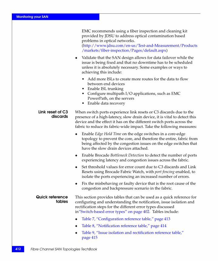
412
Monitoring your SAN
EMC recommends using a fiber inspection and cleaning kit provided by JDSU to address optical contamination based problems in optical networks. (http://www.jdsu.com/en-us/Test-and-Measurement/Products/markets/fiber-inspection/Pages/default.aspx)
◆ Validate that the SAN design allows for data failover while the issue is being fixed and that no downtime has to be scheduled unless it is absolutely necessary. Some examples or ways to achieving this include:
• Add more ISLs to create more routes for the data to flow between end devices
• Enable ISL trunking • Configure multipath I/O applications, such as EMC
PowerPath, on the servers• Enable data recovery
Link reset of C3discards
When switch ports experience link resets or C3 discards due to the presence of a high-latency, slow drain device, it is vital to detect this device and the effect it has on the different switch ports across the fabric to reduce its fabric-wide impact. Take the following measures:
◆ Enable Edge Hold Time on the edge switches in a core-edge topology to prevent the core, and therefore the entire, fabric from being affected by the congestion issues on the edge switches that have the slow drain devices attached.
◆ Enable Brocade Bottleneck Detection to detect the number of ports experiencing latency and congestion issues across the fabric.
◆ Set threshold values for error count due to C3 discards and Link Resets using Brocade Fabric Watch, with port fencing enabled, to isolate the ports experiencing an increased number of errors.
◆ Fix the misbehaving or faulty device that is the root cause of the congestion and backpressure scenario in the fabric.
Quick referencetables
This section provides tables that can be used as a quick reference for configuring and understanding the notification, issue isolation and rectification steps for the different error types discussed in“Switch-based error types” on page 402. Tables include:
◆ Table 7, “Configuration reference table,” page 413
◆ Table 8, “Notification reference table,” page 414
◆ Table 9, “Issue isolation and rectification reference table,” page 415
Fibre Channel SAN Topologies TechBook
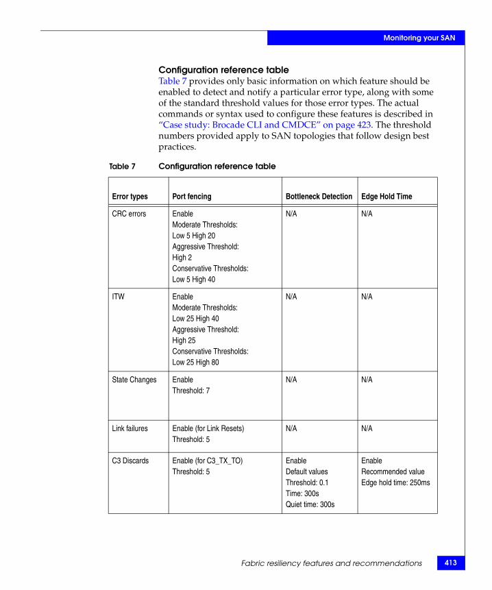
Monitoring your SAN
Configuration reference tableTable 7 provides only basic information on which feature should be enabled to detect and notify a particular error type, along with some of the standard threshold values for those error types. The actual commands or syntax used to configure these features is described in “Case study: Brocade CLI and CMDCE” on page 423. The threshold numbers provided apply to SAN topologies that follow design best practices.
Table 7 Configuration reference table
Error types Port fencing Bottleneck Detection Edge Hold Time
CRC errors EnableModerate Thresholds:Low 5 High 20Aggressive Threshold:High 2Conservative Thresholds:Low 5 High 40
N/A N/A
ITW EnableModerate Thresholds:Low 25 High 40Aggressive Threshold:High 25Conservative Thresholds:Low 25 High 80
N/A N/A
State Changes EnableThreshold: 7
N/A N/A
Link failures Enable (for Link Resets)Threshold: 5
N/A N/A
C3 Discards Enable (for C3_TX_TO)Threshold: 5
EnableDefault valuesThreshold: 0.1Time: 300sQuiet time: 300s
EnableRecommended valueEdge hold time: 250ms
Fabric resiliency features and recommendations 413
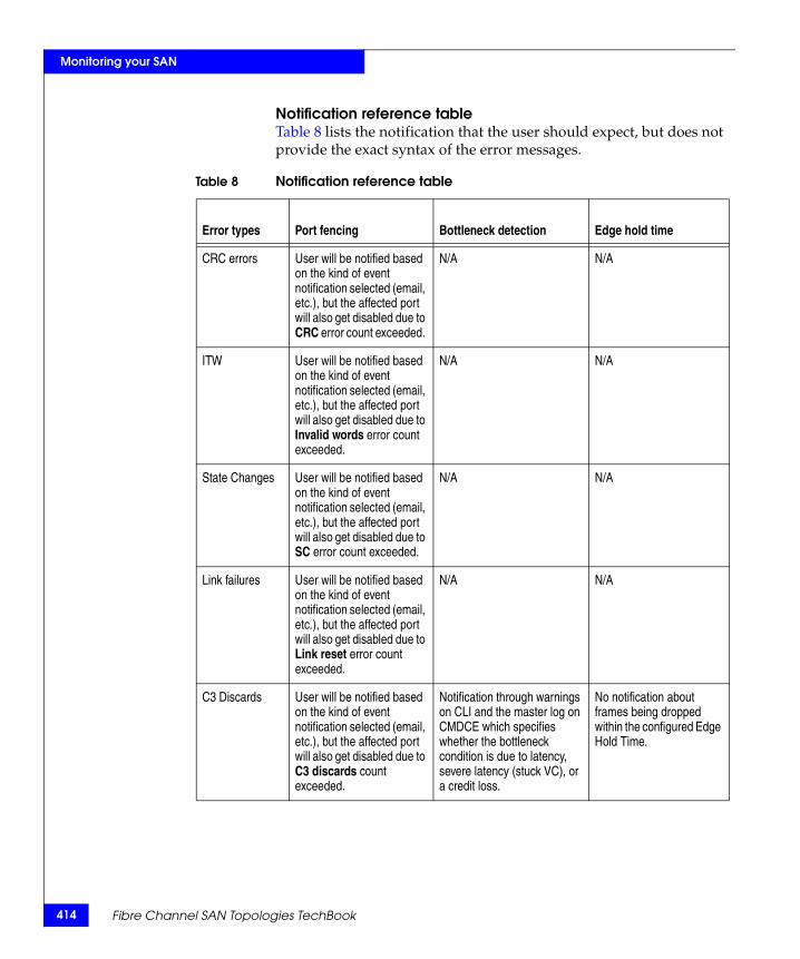
414
Monitoring your SAN
Notification reference tableTable 8 lists the notification that the user should expect, but does not provide the exact syntax of the error messages.
Table 8 Notification reference table
Error types Port fencing Bottleneck detection Edge hold time
CRC errors User will be notified based on the kind of event notification selected (email, etc.), but the affected port will also get disabled due to CRC error count exceeded.
N/A N/A
ITW User will be notified based on the kind of event notification selected (email, etc.), but the affected port will also get disabled due to Invalid words error count exceeded.
N/A N/A
State Changes User will be notified based on the kind of event notification selected (email, etc.), but the affected port will also get disabled due to SC error count exceeded.
N/A N/A
Link failures User will be notified based on the kind of event notification selected (email, etc.), but the affected port will also get disabled due to Link reset error count exceeded.
N/A N/A
C3 Discards User will be notified based on the kind of event notification selected (email, etc.), but the affected port will also get disabled due to C3 discards count exceeded.
Notification through warnings on CLI and the master log on CMDCE which specifies whether the bottleneck condition is due to latency, severe latency (stuck VC), or a credit loss.
No notification about frames being dropped within the configured Edge Hold Time.
Fibre Channel SAN Topologies TechBook

Monitoring your SAN
Issue Isolation and rectification reference tableTable 9 provides the necessary steps that the user should take if notified about a fenced port or a bottleneck condition (with or without Edge Hold Time).
Table 9 Issue isolation and rectification reference table
Error types Port fencing Bottleneck Detection Edge Hold Time
CRC errors Recommended rectification steps:Look into the physical connections and components, fix any apparent issues, clear the errors on the switch and re-enablle the fenced or disabled port .
N/A N/A
ITW Recommended first steps:Look out for bad physical connections or link bounces, resolve the issue detected, clear the errors on the switch and re-enable the fenced or disabled port .
N/A N/A
State Changes Recommended first steps:Look out for bad physical connections or link bounces, resolve the issue detected, clear the errors on the switch and re-enable the fenced or disabled port.
N/A N/A
Link failures Recommnded steps:Look out for port resets or server reboots, resolve the issue detected, clear the errors on the switch ,and re-enable the fenced or disabled port.
N/A N/A
C3 Discards Recommnded steps:Identify the congested points in the fabric and the source of congestion, fix the issue, clear the errors on the switch, and re-enable the fenced or disabled port.
Identifying the source of congestion, clearing the bottleneck condition and the errors on the switch.
Clearing the bottleneck condition and the errors on the switch.
Fabric resiliency features and recommendations 415
416
Monitoring your SAN
Brocade fabric resiliency concepts This section provides an example of a simplified two-hop, three-switch topology with a slow drain device attached to one of the switches, to better explain the following concepts:
◆ The difference between latency and congestion ◆ How latency on a switch can propagate through the fabric ◆ Different types of latencies based on severity◆ How Bottleneck Detection, along with other best practices, can be
used to mitigate latency effects
The following sections will help clarify these concepts:
◆ “Latency and congestion bottleneck conditions” on page 416◆ “Latency severities” on page 419◆ “Latency detection, notification, isolation, and mitigation ” on
page 420
Latency and congestion bottleneck conditionsA device that experiences latencies and responds more slowly than expected is known as a slow drain, or latency, device. This device does not return buffer credits (through R_RDY primitives) to the transmitting switch to which it is directly attached fast enough to support the offered load, even though the offered load is less than the maximum physical capacity of the link connected to the device. An example is shown in Figure 79 on page 417.
Note: For a detailed explanation and example of a slow drain (latency) device, refer to the Networked Storage Concepts and Protocols TechBook, available on the E-Lab Navigator, Topology Resource Center tab.
Once all available credits are exhausted, the switch port connected to the device needs to hold additional outbound frames until a buffer credit is returned by the slow drain device. When the device continues to not respond in a timely fashion, the transmitting switch is forced to hold frames for longer periods of time, resulting in high buffer occupancy. This, in turn, results in the switch lowering the rate it returns buffer credits to other transmitting switches attached to it. This effect propagates through switches, and potentially multiple switches with devices attempting to send frames to devices attached
Fibre Channel SAN Topologies TechBook
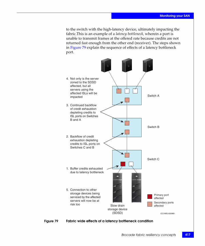
Monitoring your SAN
to the switch with the high-latency device, ultimately impacting the fabric.This is an example of a latency bottleneck, wherein a port is unable to transmit frames at the offered rate because credits are not returned fast enough from the other end (receiver). The steps shown in Figure 79 explain the sequence of effects of a latency bottleneck port.
Figure 79 Fabric wide effects of a latency bottleneck condition
Switch A
Switch B
Switch C
Slow drainstorage device
(SDSD)
Not only is the server zoned to the SDSD affected, but all servers using the affected ISLs will be impacted
4.
Connection to other storage devices being serviced by the affected servers will now be at risk too
5.
Continued backflow of credit exhaustion depleting credits to ISL ports on Switches B and A
3.
Buffer credits exhausted due to latency bottleneck
1.
Backflow of credit exhaustion depleting credits to ISL ports on Switches C and B
2.
ICO-IMG-000989
Primary port affected
Secondary ports affected
Brocade fabric resiliency concepts 417
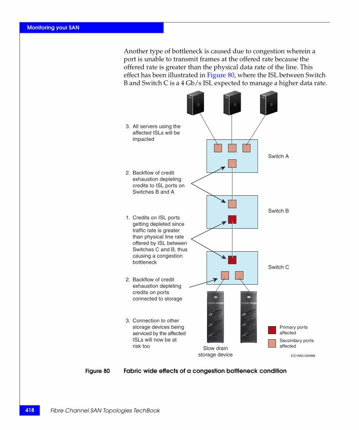
418
Monitoring your SAN
Another type of bottleneck is caused due to congestion wherein a port is unable to transmit frames at the offered rate because the offered rate is greater than the physical data rate of the line. This effect has been illustrated in Figure 80, where the ISL between Switch B and Switch C is a 4 Gb/s ISL expected to manage a higher data rate.
Figure 80 Fabric wide effects of a congestion bottleneck condition
Switch A
Switch B
Switch C
Slow drainstorage device
All servers using the affected ISLs will be impacted
3.
Connection to other storage devices being serviced by the affected ISLs will now be at risk too
3.
Backflow of credit exhaustion depleting credits to ISL ports on Switches B and A
2.
Backflow of credit exhaustion depleting credits on ports connected to storage
2.
Credits on ISL ports getting depleted since traffic rate is greater than physical line rate offered by ISL between Switches C and B, thus causing a congestion bottleneck
1.
ICO-IMG-000988
Primary ports affected
Secondary ports affected
Fibre Channel SAN Topologies TechBook
Monitoring your SAN
Latency severitiesThe presence of a slow drain device or an ISL with a low physical data rate, as compared to the actual offered traffic rate, can have a disruptive fabric-wide impact. However, the impact to the fabric, and other traffic flows, varies based on the severity of the latency exhibited by the device. The longer the delay caused by the device in returning credits to the switch, the more severe the problem.
The following latency severities are discussed in this section:
◆ “Moderate device latencies ” on page 419
◆ “Severe device latencies ” on page 419
Moderate devicelatencies
Moderate device latencies are defined as those not severe enough to cause frame loss. Frame loss typically occurs above 100 ms.
If the time between successive credit returns by the device is between a few hundred microseconds to tens of milliseconds, then the device exhibits moderate latencies since this delay is not typically enough to cause frame loss. This causes a drop in performance of traffic flows using the fabric, but typically does not cause frame drops or I/O failures.
When a device exhibits moderate latency behavior, applications may see a drop in performance but not usually I/O failure. The higher the latency, the greater the chance that an end user will experience degraded performance.
Severe devicelatencies
Severe device latencies result in frame loss, which triggers the host SCSI stack to detect failures and to retry I/Os. This process can take tens of seconds, or possibly as long as 30 – 60 seconds, which can cause a very noticeable application delay and potentially result in application errors.
If the time between successive credit returns by the device is in excess of 100 milliseconds, then the device is exhibiting severe latency. When a device exhibits severe latency, the switch is forced to hold frames for excessively long periods of time, possibly hundreds of milliseconds. When this time becomes greater than the established timeout threshold, the switch drops the frame (per Fibre Channel standards). This leads to the frame loss in switches or the C3 (Class 3) discards discussed in “Switch-based error types” on page 402.
Since the effect of device latencies often spreads through the fabric, frames can be dropped due to timeouts, not just on the F_Port to
Brocade fabric resiliency concepts 419
420
Monitoring your SAN
which the misbehaving device is connected but also on E_Ports carrying traffic to the F_Port.
Dropped frames typically cause I/O errors that result in a host retry and can result in significant decreases in application performance. The implications of this behavior are compounded and exacerbated by the fact that frame drops on the affected F_Port (device) result not only in I/O failures to the misbehaving device, which would be expected, but also frame drops on E_Ports may cause I/O failures for unrelated traffic flows involving other hosts, which would not typically be expected.
Latency detection, notification, isolation, and mitigation The following information is included in this section :
◆ “Bottleneck Detection” on page 420
◆ “Fabric Watch for Timeout Notification on F_Ports ” on page 421
◆ “Port fencing to isolate a misbehaving bottlenecked port” on page 421
◆ “Edge Hold Time” on page 422
◆ “Mitigation action based on bottleneck detection ” on page 422
◆ “Proactive mitigation” on page 422
Bottleneck DetectionAs discussed in “Bottleneck Detection” on page 408, enabling Brocade’s Bottleneck Detection feature is a recommended best practice to detect devices that exhibit latency and congestion-based scenarios. Bottleneck Detection is a comprehensive feature that can be used to detect a wide range of device latencies from mild to severe.
Once Bottleneck Detection is enabled, the switch monitors F_Ports for latency symptoms. Specifically, it looks for conditions in which the time delay between successive buffer credit returns from a device is higher than expected. When the condition is detected, Bottleneck Detection reports latency bottlenecks at F_Ports based on user configurable thresholds. These reports can then be leveraged to:
◆ Determine the severity and duration of the latency behavior
◆ Determine the specific device port on which device latencies are occurring
Fibre Channel SAN Topologies TechBook
Monitoring your SAN
◆ Determine the actual device latency in the range of 100 microseconds to hundreds of milliseconds
Detecting bottleneck scenarios, notification and alerting mechanisms, and isolation of the issue aid in preventing fabric-wide congestion. Fabric Watch, port fencing, and configuring the Edge Hold Time are other features and best practices to meet these objectives.
Fabric Watch for Timeout Notification on F_Ports It is a recommended best practice to use Fabric Watch to detect frame timeouts, that is, frames that have been dropped because of severe latency conditions. The Fabric Watch C3TX_TO, introduced in Brocade FOS v6.3.x for 8 Gb/s ports and available in Brocade FOS v6.3.1b/6.4.0 and later for 4 Gbp/ ports, should be used to track the number of frame timeouts. If the number of timed-out frames on an F_Port exceeds the currently effective threshold settings, Fabric Watch notifies the user through one of the following mechanisms:
◆ Send an SNMP trap
◆ Log a RASlog message
◆ Send an email alert
◆ Log a SYSlog message
Port fencing to isolate a misbehaving bottlenecked portWhen a misbehaving device exhibits extremely high latencies causing frame timeouts, it is likely also causing a severe fabric impact and should be removed from the fabric. Port fencing, based on timeouts, is an optional feature that can be used to quarantine a high latency device and mitigate the impact on the fabric (8 Gb/s platform support available in Brocade FOS 6.3 and later; 4 Gb/s platform support available in Brocade FOS 6.3.1b and later). Brocade recommends enabling port fencing for transmit timeouts on F_Ports.
Once port fencing is configured, when the number of frames dropped due to timeouts on an F_Port reaches a user-configured threshold, the port is fenced (blocked). This disables the port, requiring user intervention to bring it back online. Once the F_Port of the offending device is fenced, no further actions are required. The default or recommended threshold settings can safely disable the misbehaving device, preventing an impact to the fabric without causing a false trigger (fencing a port when there is not a high-latency device).
Brocade fabric resiliency concepts 421
422
Monitoring your SAN
Edge Hold TimeThis applies primarily to a core edge switch topology.To reduce frame drops on E_Ports on core switches, the edge switches can be configured to have a shorter Hold Time compared to the core switches by using the Edge Hold Time feature (available in Brocade FOS 6.3.1b and later). This setting lowers the Hold Time on the edge of the network, which reduces the probability of frame loss on the core of the network, effectively mitigating the impact of the misbehaving device.
It is a recommended best practice to enable the Edge Hold Time feature and to reduce timeouts on unrelated flows.
Mitigation action based on bottleneck detection Brocade FOS v6.4.0 and later includes an enhancement to Bottleneck Detection that allows the switch to provide some fabric-level mitigation when device latency is detected but port fencing thresholds have not yet been reached.
When latency is detected on a port, frames held in the transmit port connected to the misbehaving device are dropped for a short period of time. This allows the switch to return credits to other transmitting switches, allowing other traffic flows to move at a faster rate. This protects other flows from a severe performance drop resulting from a single misbehaving device. If a misbehaving device continues to exhibit latencies for several seconds, the port is disabled via port fencing, if port fencing has been enabled and configured.
These best practices need to be implemented once the fabric has been configured to adhere to the design or configuration best practices.
Proactive mitigation Fabrics can be architected to mitigate some impacts of device latency. Isolating the device flows (host/storage pair) that exhibit high latencies by either putting them in their own fabric or on their own blade/switch will contain the impact of the latencies to the fabric or blade/switch containing the high-latency device flows. Features, such as Brocade Integrated Routing (Fibre Channel Routing) and local switching, provide architectural-level solutions that limit the need for more complex monitoring and mitigation capabilities. However, using fabric design as a protection mechanism does require some knowledge of which devices are likely to exhibit latency.
Fibre Channel SAN Topologies TechBook
Monitoring your SAN
Configuring FS features case studyThis section includes information for the following case study:
◆ “Case study: Brocade CLI and CMDCE” on page 423
Case study: Brocade CLI and CMDCE
This case study example demonstrates how the Brocade CLI and the Connectrix Manager Data Center Edition (CMDCE) can be used to enable the resiliency features described in “Fabric resiliency features and recommendations” on page 408. Snapshots of expected outcomes in the presence of a high latency device causing C3 discards or link errors are also provided.
It is important to note that:
◆ Bottleneck detection can be configured and monitored via CLI only (pre Brocade FOS v7.x).
◆ Edge Hold Time is easily configured via CLI on a switch-by-switch basis.
◆ Port fencing is more easily configurable using CMDCE.
This section contains the following examples:
◆ “Two initiators and targets no congestion and backpressure” on page 423
◆ “Two Initiators and one slow drain causes congestion or backpressure” on page 424
Two initiators and targets no congestion and backpressureFor this example, assume that a initiator with two HBA ports is zoned so that each HBA port has access to one target; for example:
◆ HBA port 1 is zoned to Target 1
◆ HBA port 2 is zoned to Target 2
Figure 81 on page 424 shows an uncongested environment containing multiple initiators, each one transmitting to their own target.
Configuring FS features case study 423
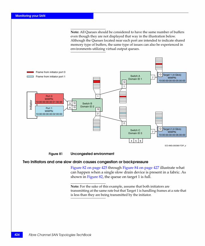
424
Monitoring your SAN
Note: All Queues should be considered to have the same number of buffers even though they are not displayed that way in the illustration below. Although the Queues located near each port are intended to indicate shared memory type of buffers, the same type of issues can also be experienced in environments utilizing virtual output queues.
Figure 81 Uncongested environment
Two Initiators and one slow drain causes congestion or backpressureFigure 82 on page 425 through Figure 84 on page 427 illustrate what can happen when a single slow drain device is present in a fabric. As shown in Figure 82, the queue on target 1 is full.
Note: For the sake of this example, assume that both initiators are transmitting at the same rate but that Target 1 is handling frames at a rate that is less than they are being transmitted by the initiator.
Initi
ator
ICO-IMG-000369-TOP_a
Q
Q
2
1
1
2
Switch CDomain ID 3
Switch BDomain ID 2
3
4
4 5 6
7
Port 0WWPN:
10:00:00:00:00:01:00:00
Port 1WWPN:
10:00:00:00:00:02:00:00
Target 2 (4 Gb/s)WWPN:
10:00:00:00:00:06:00:00
Q
Switch ADomain ID 1 7
Target 1 (4 Gb/s)WWPN:
10:00:00:00:00:05:00:00
QFrame from initiator port 0
Frame from initiator port 1
Q
Q
Fibre Channel SAN Topologies TechBook
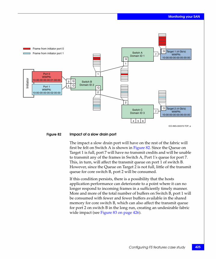
Monitoring your SAN
Figure 82 Impact of a slow drain port
The impact a slow drain port will have on the rest of the fabric will first be felt on Switch A is shown in Figure 82. Since the Queue on Target 1 is full, port 7 will have no transmit credits and will be unable to transmit any of the frames in Switch A, Port 1's queue for port 7. This, in turn, will affect the transmit queue on port 1 of switch B. However, since the Queue on Target 2 is not full, little of the transmit queue for core switch B, port 2 will be consumed.
If this condition persists, there is a possibility that the hosts application performance can deteriorate to a point where it can no longer respond to incoming frames in a sufficiently timely manner. More and more of the total number of buffers on Switch B, port 1 will be consumed with fewer and fewer buffers available in the shared memory for core switch B, which can also affect the transmit queue for port 2 on switch B in the long run, creating an undesirable fabric wide impact (see Figure 83 on page 426).
Initi
ator
ICO-IMG-000370-TOP_a
Q
Q
2
1
1
2
Switch CDomain ID 3
Switch BDomain ID 2
3
4
4 5 6
7
Port 0WWPN:
10:00:00:00:00:01:00:00
Port 1WWPN:
10:00:00:00:00:02:00:00
Target 2 (4 Gb/s)WWPN:
10:00:00:00:00:06:00:00
Q
Switch ADomain ID 1 7
Target 1 (4 Gb/s)WWPN:
10:00:00:00:00:05:00:00
QFrame from initiator port 0
Frame from initiator port 1
Q
Q
Configuring FS features case study 425
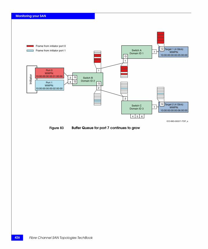
426
Monitoring your SAN
Figure 83 Buffer Queue for port 7 continues to grow
Initi
ator
ICO-IMG-000371-TOP_a
Q
Q
2
1
1
2
Switch CDomain ID 3
Switch BDomain ID 2
3
4
4 5 6
7
Port 0WWPN:
10:00:00:00:00:01:00:00
Port 1WWPN:
10:00:00:00:00:02:00:00
Target 2 (4 Gb/s)WWPN:
10:00:00:00:00:06:00:00
Q
Switch ADomain ID 1 7
Target 1 (4 Gb/s)WWPN:
10:00:00:00:00:05:00:00
QFrame from initiator port 0
Frame from initiator port 1
Q
Q
Fibre Channel SAN Topologies TechBook
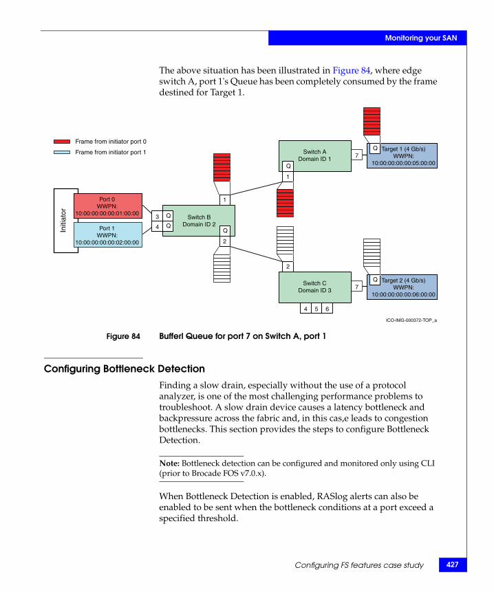
Monitoring your SAN
The above situation has been illustrated in Figure 84, where edge switch A, port 1's Queue has been completely consumed by the frame destined for Target 1.
Figure 84 Bufferl Queue for port 7 on Switch A, port 1
Configuring Bottleneck Detection
Finding a slow drain, especially without the use of a protocol analyzer, is one of the most challenging performance problems to troubleshoot. A slow drain device causes a latency bottleneck and backpressure across the fabric and, in this cas,e leads to congestion bottlenecks. This section provides the steps to configure Bottleneck Detection.
Note: Bottleneck detection can be configured and monitored only using CLI (prior to Brocade FOS v7.0.x).
When Bottleneck Detection is enabled, RASlog alerts can also be enabled to be sent when the bottleneck conditions at a port exceed a specified threshold.
Initi
ator
ICO-IMG-000372-TOP_a
Q
Q
2
1
1
2
Switch CDomain ID 3
Switch BDomain ID 2
3
4
4 5 6
7
Port 0WWPN:
10:00:00:00:00:01:00:00
Port 1WWPN:
10:00:00:00:00:02:00:00
Target 2 (4 Gb/s)WWPN:
10:00:00:00:00:06:00:00
Q
Switch ADomain ID 1 7
Target 1 (4 Gb/s)WWPN:
10:00:00:00:00:05:00:00
QFrame from initiator port 0
Frame from initiator port 1
Q
Q
Configuring FS features case study 427
428
Monitoring your SAN
On the edge switches A and C with target port connections, complete the following steps:
1. Log in with admin level privileges.
2. Enter bottleneckmon --enable to enable Bottleneck Detection on the F_Ports or ports where the target devices are attached by using the following command:
bottleneckmon --enable [ -alert ] [ -thresh threshold ] [ -time window ] [ -qtime quiet_time] [slot/]portlist [[slot/]portlist]...
For this example, on switch A run:
Switch_A:admin> bottleneckmon –enable -alert 7 Switch_A:admin> bottleneckmon --enable -alert1
On switch C, run:
Switch_C:admin> bottleneckmon --enable -alert 7
If the alert parameter is not specified, alerts are not sent, but a history of bottleneck conditions for the port can be viewed. The thresh, time, and qtime parameters are also ignored if the alert parameter is not specified.
RASlog alerts can be enabled or disabled along with configuration of the following parameters:
• Threshold – The percentage of 1-second intervals required to generate an alert
• Time – The time window in seconds in which bottleneck conditions are monitored and compared against the threshold
Note: If the time parameter is changed, it should be set to 300 or higher.
• Quiet Time options – Time in seconds between bottleneck alerts
The default settings for Bottleneck Detection are the recommended settings. The default values for the threshold, time and qtime are 0.1, 300secs, and 300secs. With these default settings, alerts are logged when a port is experiencing a bottleneck condition for 10% of the time (default value) over any period of 300 seconds (default value) with a minimum of 300 seconds (default value) between alerts.
Fibre Channel SAN Topologies TechBook
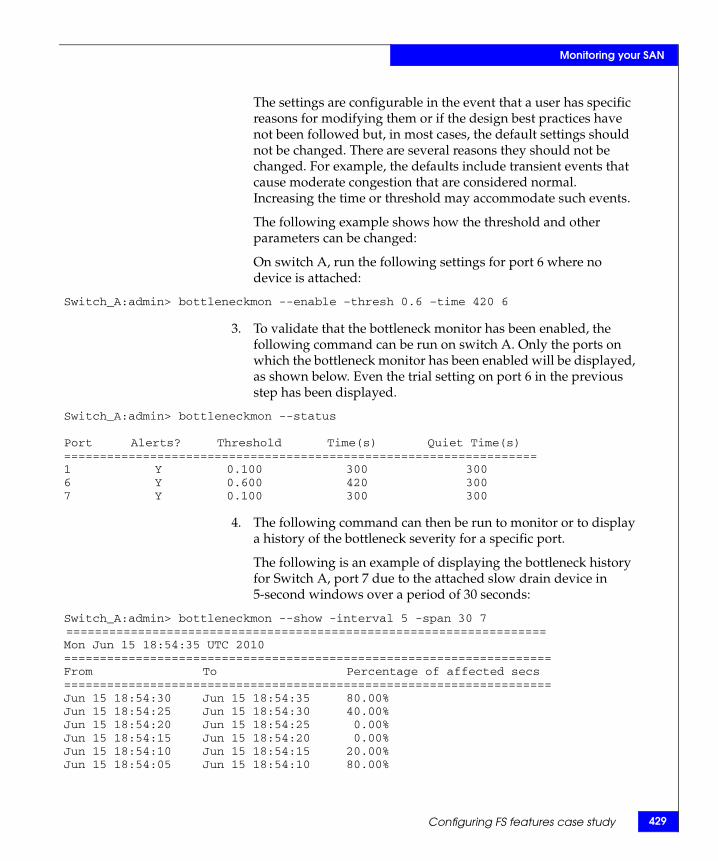
Monitoring your SAN
The settings are configurable in the event that a user has specific reasons for modifying them or if the design best practices have not been followed but, in most cases, the default settings should not be changed. There are several reasons they should not be changed. For example, the defaults include transient events that cause moderate congestion that are considered normal. Increasing the time or threshold may accommodate such events.
The following example shows how the threshold and other parameters can be changed:
On switch A, run the following settings for port 6 where no device is attached:
Switch_A:admin> bottleneckmon --enable –thresh 0.6 –time 420 6
3. To validate that the bottleneck monitor has been enabled, the following command can be run on switch A. Only the ports on which the bottleneck monitor has been enabled will be displayed, as shown below. Even the trial setting on port 6 in the previous step has been displayed.
Switch_A:admin> bottleneckmon --status
Port Alerts? Threshold Time(s) Quiet Time(s) ==================================================================1 Y 0.100 300 3006 Y 0.600 420 300 7 Y 0.100 300 300
4. The following command can then be run to monitor or to display a history of the bottleneck severity for a specific port.
The following is an example of displaying the bottleneck history for Switch A, port 7 due to the attached slow drain device in 5-second windows over a period of 30 seconds:
Switch_A:admin> bottleneckmon --show -interval 5 -span 30 7 ===================================================================Mon Jun 15 18:54:35 UTC 2010====================================================================From To Percentage of affected secs ====================================================================Jun 15 18:54:30 Jun 15 18:54:35 80.00% Jun 15 18:54:25 Jun 15 18:54:30 40.00% Jun 15 18:54:20 Jun 15 18:54:25 0.00% Jun 15 18:54:15 Jun 15 18:54:20 0.00% Jun 15 18:54:10 Jun 15 18:54:15 20.00% Jun 15 18:54:05 Jun 15 18:54:10 80.00%
Configuring FS features case study 429
430
Monitoring your SAN
5. If the bottleneckmon --enable –alert option is selected, RASlog alerts will be sent when the bottleneck conditions at a port exceed a specified threshold.
If the alert parameter is not specified, alerts are not sent, but a history of bottleneck conditions for the port can be viewed. The following are kinds of alerts that the user can expect to see:
• The following is an example of a bottleneck detection alert on an F_Port (Switch A, port 7):
2011/06/15-18:53:47, [AN-1003], 1, FID 128, WARNING, Switch_A, Latency bottleneck at slot 0, port 7. 40.00 percent of last 300 seconds were affected. Avg. time b/w transmits 677.6751 us.
• The following is an example of a congestion alert on an E_Port (Switch A, port 1):
2011/06/15-18:55:32, [AN-1004], 2, FID 128, WARNING, Switch_A, Slot 0, port 1 is a congestion bottleneck. 80.00 percent of last 300 seconds were affected by this condition.
6. While enabling the bottleneck monitor and alerting, the bottleneck detection-based mitigation action can be enabled as follows on all F_Ports in a switch:
Switch_A:admin> bottleneckmon --enable -act
• To enable/disable mitigation action after Bottleneck Detection has been enabled on all F_Ports, use the following commands on Switch A:
Switch_A:admin> bottleneckmon --config -act OR Switch_A:admin> bottleneckmon --config -noact
• To enable/disable mitigation action after enabling Bottleneck Detection for a specific port, for e.g. port 7 on switch A, use:
Switch_A:admin> bottleneckmon --config -act 7 Switch_A:admin> bottleneckmon --config –noact 7
All F_Ports with Bottleneck Detection enabled and the -act flag set are subject to mitigation action. Ports excluded from Bottleneck Detection (using the --exclude operation) are also excluded from mitigation action.
Using Bottleneck Detection, the misbehaving ports can be identified. But, what if one does not want the affected port to impact the other ports? For example, in this case study, not only is the port attached to the slow drain device affected due to a latency condition, but it has also impacted the other port on the switch due to backpressure. This
Fibre Channel SAN Topologies TechBook
Monitoring your SAN
backpressure effect can be prevented by fencing or disabling the impacted port. Implementing port fencing automatically activates this behavior.
Enabling port fencing
Port fencing monitors ports for erratic behavior and disables a port if specified error conditions are met. It can be configured using the CLI and the Connectrix Manager Data Center Edition (CMDCE). This section discusses how both these interfaces can be used to configure port fencing.
Using the CLI The port fencing CLI is part of Fabric Watch and is used to enable error reporting on all ports of a specified type and configure the ports to report errors for a specific area. Supported port types include E_Ports and F_Ports. The specified port type can be configured to report errors for one or more areas.
This case study uses the portfencing command to configure port fencing for C3_TX_TO. As explained in “Switch-based error types” on page 402, C3 discards can occur due to slow drain.
To configure port fencing for C3_TX-TO using the CLI, complete the following steps:
1. To enable port fencing on all Fx_Ports on the switch, for C3_TX_TO, run the following command on the CLI:
Switch_A:admin> portfencing --enable fop-port –area C3TX_TO
2. Use portThconfig to customize port fencing thresholds:
For C3_TX_TO, threshold = 5 (and notification action selected is viewing port logs)
Switch_A:admin> portThConfig --set port -area C3TX_TO -highthreshold -value 5 -trigger above –action portlog
If the custom settings have to be applied, the following command should be run:
Switch_A:admin> portThConfig --apply port -area C3TX_TO –action_level cust -thresh_level custom
3. To verify the settings in steps 1 and 2, execute the following steps:
Configuring FS features case study 431
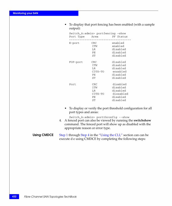
432
Monitoring your SAN
• To display that port fencing has been enabled (with a sample output):
Switch_A:admin> portfencing –showPort Type Area PF Status------------------------------------E-port CRC enabled
ITW enabledLR disabledPE disabledST disabled
FOP-port CRC disabledITW disabledLR disabledC3TX-TO ensabledPE disabledST disabled
Port CRC disabledITW disabledLR disabledC3TX-TO dissabledPE disabledST disabled
• To display or verify the port threshold configuration for all port types and areas:
Switch_A:admin> portthconfig --show4. A fenced port can also be viewed by running the switchshow
command. The fenced port will show up as disabled with the appropriate reason or error type.
Using CMDCE Step 1 through Step 4 in the “Using the CLI,” section can can be execute d e using CMDCE by completing the following steps:
Fibre Channel SAN Topologies TechBook
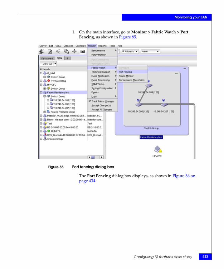
Monitoring your SAN
1. On the main interface, go to Monitor > Fabric Watch > Port Fencing, as shown in Figure 85.
Figure 85 Port fencing dialog box
The Port Fencing dialog box displays, as shown in Figure 86 on page 434.
Configuring FS features case study 433
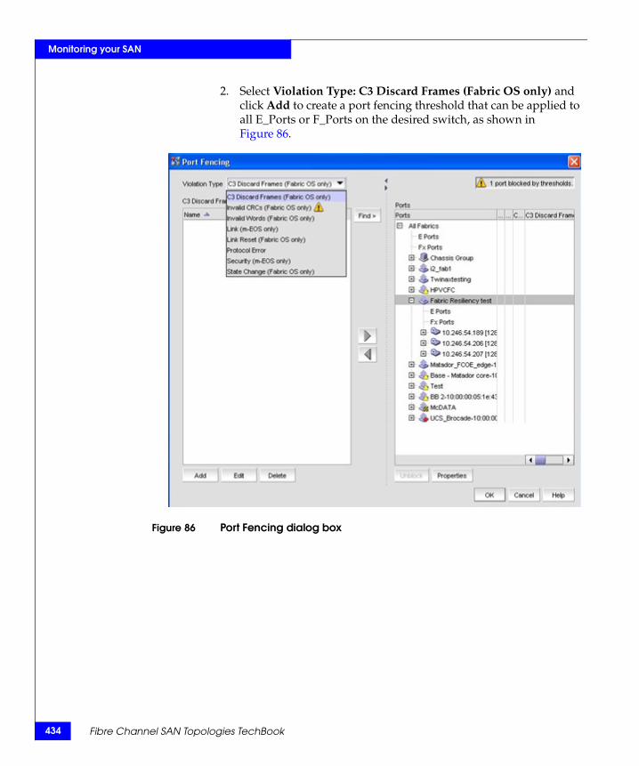
434
Monitoring your SAN
2. Select Violation Type: C3 Discard Frames (Fabric OS only) and click Add to create a port fencing threshold that can be applied to all E_Ports or F_Ports on the desired switch, as shown in Figure 86.
Figure 86 Port Fencing dialog box
Fibre Channel SAN Topologies TechBook
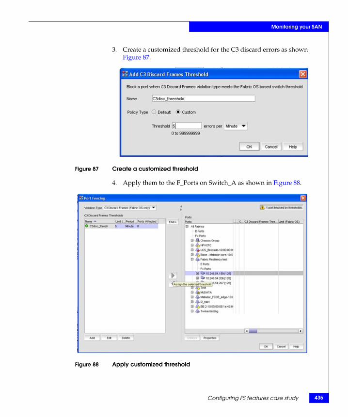
Monitoring your SAN
3. Create a customized threshold for the C3 discard errors as shown Figure 87.
Figure 87 Create a customized threshold
4. Apply them to the F_Ports on Switch_A as shown in Figure 88.
Figure 88 Apply customized threshold
Configuring FS features case study 435
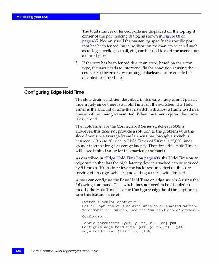
436
Monitoring your SAN
The total number of fenced ports are displayed on the top right corner of the port fencing dialog as shown in Figure 88 on page 435. Not only will the master log specify the specific port that has been fenced, but a notification mechanism selected such as raslogs, portlogs, email, etc., can be used to alert the user about a fenced port.
5. If the port has been fenced due to an error, based on the error type, the user needs to intervene, fix the condition causing the error, clear the errors by running statsclear, and re-enable the disabled or fenced port.
Configuring Edge Hold TimeThe slow drain condition described in this case study cannot persist indefinitely since there is a Hold Timer on the switches. The Hold Timer is the amount of time that a switch will allow a frame to sit in a queue without being transmitted. When the timer expires, the frame is discarded.
The HoldTimer for the Connectrix B Series switches is 500ms. However, this does not provide a solution to the problem with the slow drain since average frame latency time through a switch is between 600 ns to 20 usec. A Hold Timer of 500ms is 25,000 times greater than the longest average latency. Therefore, this Hold Timer will have limited value for this particular scenario.
As described in “Edge Hold Time” on page 409, the Hold Time on an edge switch that has the high latency device attached can be reduced by 5 times to 100ms to relieve the backpressure effect on the core serving other edge switches, preventing a fabric-wide impact.
A user can configure the Edge Hold Time on edge switch A using the following command. The switch does not need to be disabled to modify the Hold Time. Use the Configure edge hold time option to turn this feature on or off.
Switch_A:admin> configureNot all options will be available on an enabled switch. To disable the switch, use the "switchDisable" command.
Configure...
Fabric parameters (yes, y, no, n): [no] yes Configure edge hold time (yes, y, no, n): [yes] Edge hold time: (100..500) [100]
Fibre Channel SAN Topologies TechBook

Monitoring your SAN
The Edge Hold Time value is persistently stored in the configuration file. All configuration file operations, such as configupload and configdownload, are supported for this feature.
Note: This setting is available only in Brocade FOS v6.3.1b and later.
Configuring FS features case study 437
438
Monitoring your SAN
SummarySAN performance monitoring tools are gaining more attention with some of the newer switch firmware releases. Just as proper SAN administering and design are considered best practices to manage your SAN, proper SAN monitoring best practices are also vital.
Effective SAN monitoring not only assists in detecting any existing error conditions in a SAN, but also makes performance adjustments and aids in decisions for future capacity planning. This chapter provided recommended best practices for monitoring your SAN. These best practices are essential for large and complex SANs that manage critical data and have optimal performance requirements.
Fibre Channel SAN Topologies TechBook
5Invisible Body Tag
This chapter provides a case study for Brocade Virtual Fabrics.
◆ Brocade Virtual Fabrics case study overview ................................ 440◆ Objectives of Virtual Fabrics architecture....................................... 441◆ Logical Switch capability .................................................................. 442◆ Virtual Fabrics and ISLs .................................................................... 445◆ How to configure Brocade Virtual Fabrics case study ................. 448◆ Brocade Virtual Fabrics versus traditional Cisco Virtual SANs.. 466
Brocade VirtualFabrics Case Study
Brocade Virtual Fabrics Case Study 439
440
Brocade Virtual Fabrics Case Study
Brocade Virtual Fabrics case study overviewBrocade Virtual Fabrics (VFs) allows a physical Brocade or Connectrix B series switch to be partitioned into multiple Logical Switches, which can in turn be interconnected to form Logical Fabrics. Each Logical Switch acts as an independent fabric component in terms of protocol and management. Each Logical Switch has its own fabric services (name server, zoning, etc.), configuration (port, switch, fabric, etc.), and fabric characteristics (operating mode, addressing, etc.).
As the number and size of SANs continue to grow, the complexity of managing these SANs has become a main concern. Large MetaSANs pose problems including fragmented SAN islands, lack of isolation in meta SANs, and limited scalability. For more information and examples showing MetaSANS, refer to "SAN routing concepts" in the Networked Storage Concepts and Protocols TechBook, available through the E-Lab Interoperability Navigator, Topology Resource Center tab, at http://elabnavigator.EMC.com. The Virtual Fabrics feature introduced with Brocade Fabric OS v6.2.x provides solutions to these problems.
The Virtual Fabrics feature is supported on the Connectrix ED-DCX-B, ED-DCX-4S-B, DS-5300B, and DS-5100B switch platforms beginning with Brocade Fabric OS v6.2.0e.
The Virtual Fabric concepts discussed in this section will become clearer as we examine a case study for creating and configuring logical or virtual fabrics in “How to configure Brocade Virtual Fabrics case study” on page 448.
Note: If you are used to working with Cisco VSANs, please review “Brocade Virtual Fabrics versus traditional Cisco Virtual SANs” on page 466 before proceeding. This section outlines specific details that the user must be aware of before configuring Brocade VFs.
The following information is provided in this section:◆ “Objectives of Virtual Fabrics architecture” on page 441◆ “Logical Switch capability” on page 442◆ “Virtual Fabrics and ISLs” on page 445◆ “How to configure Brocade Virtual Fabrics case study” on
page 448◆ “Brocade Virtual Fabrics versus traditional Cisco Virtual SANs”
on page 466
Fibre Channel SAN Topologies TechBook
Brocade Virtual Fabrics Case Study
Objectives of Virtual Fabrics architectureThe objective of the Virtual Fabrics architecture is to provide the following:
◆ Virtualize hardware boundaries: Traditionally, the SAN design/management is performed at the granularity of a physical switch. The Virtual Fabrics feature allows SAN design to be made at the granularity of a port.
◆ Isolation: The Virtual Fabrics feature provides isolation across different SANs that are part of the same metaSAN.
The following levels of isolation are provided:
• Management isolation: The different SANs are part of different management domains and are isolated from each other.
• Protocol isolation: Protocol events do not cross SAN boundaries.
• Data path isolation: The physical links used by the different SANs can be isolated such that no two SANs share the same physical link.
◆ Scalability: The Virtual Fabrics architecture segments the SANs in a metaSAN such that each of the SANs can scale independently. The scalability of the meta-SAN is decoupled from the scalability of the individual SANs.
Objectives of Virtual Fabrics architecture 441
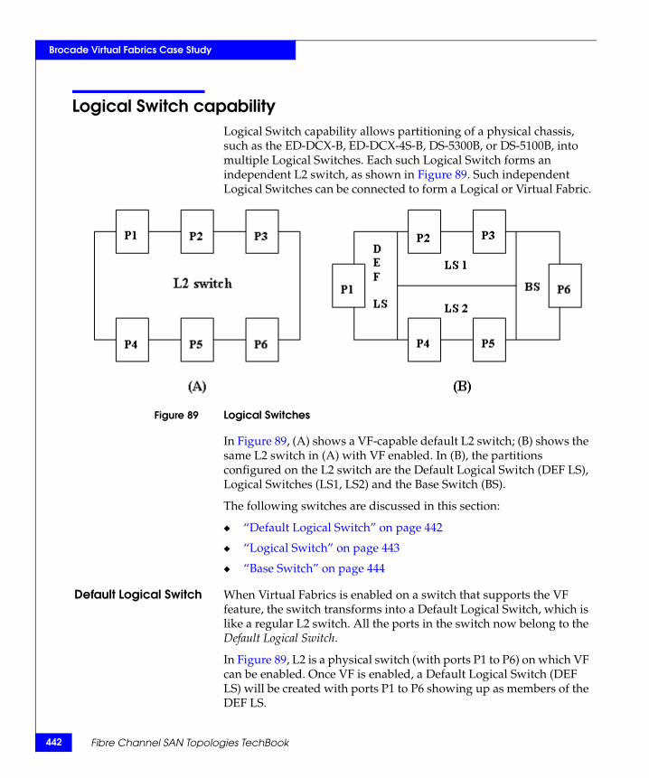
442
Brocade Virtual Fabrics Case Study
Logical Switch capabilityLogical Switch capability allows partitioning of a physical chassis, such as the ED-DCX-B, ED-DCX-4S-B, DS-5300B, or DS-5100B, into multiple Logical Switches. Each such Logical Switch forms an independent L2 switch, as shown in Figure 89. Such independent Logical Switches can be connected to form a Logical or Virtual Fabric.
Figure 89 Logical Switches
In Figure 89, (A) shows a VF-capable default L2 switch; (B) shows the same L2 switch in (A) with VF enabled. In (B), the partitions configured on the L2 switch are the Default Logical Switch (DEF LS), Logical Switches (LS1, LS2) and the Base Switch (BS).
The following switches are discussed in this section:
◆ “Default Logical Switch” on page 442
◆ “Logical Switch” on page 443
◆ “Base Switch” on page 444
Default Logical Switch When Virtual Fabrics is enabled on a switch that supports the VF feature, the switch transforms into a Default Logical Switch, which is like a regular L2 switch. All the ports in the switch now belong to the Default Logical Switch.
In Figure 89, L2 is a physical switch (with ports P1 to P6) on which VF can be enabled. Once VF is enabled, a Default Logical Switch (DEF LS) will be created with ports P1 to P6 showing up as members of the DEF LS.
Fibre Channel SAN Topologies TechBook

Brocade Virtual Fabrics Case Study
Logical Switch A switch/chassis can be divided into multiple Logical Switches (LS). Each Logical Switch acts as a L2 switch.
The user must configure each port with a Fabric ID (FID) that uniquely maps a port to a Logical Switch. Any given port can only be in one Logical Switch. All ports with the same FID are a part of the same Logical Switch. Thus, the FID is the attribute that distinguishes one Logical Switch from the other.
As the user initially allocates ports to new Logical Switches, those ports are removed from the Default Logical Switch and assigned to the specific Logical Switch that is being created.
Note: Some types of ports and blades cannot be removed from the Default Logical Switch. This information is provided in the EMC Connectrix B Series Administrator’s Guide for FOS v6.2.x.
A port is automatically disabled when being assigned to a Logical Switch. User can also move ports from one Logical Switch to another. Each Logical Switch can have as many ports as available in the chassis. For FOS v6.2, the limits for the number of Logical Switches per product are shown in Table 10.
In Figure 89 on page 442, two Logical Switches, LS1 and LS2, each with unique FIDs, were created by the user. Note that the DEF LS is also assigned a default Fabric ID of 128. Ports P2 and P3 were added to LS1 from the DEF LS, while ports P4 and P5 were added to LS2 from the DEF LS.
Each Logical Switch can be configured to have its own preferred Domain ID and other fabric parameters. During Virtual Fabric (or Logical Fabric) formation, any conflict will be resolved as it would be for a regular L2 switch fabric.
Table 10 Number of Logical Switches supported per product
Product Maximum number of Logical Switches per chassis (includes default switch)
ED-DCX-B 8
ED-DCX-4S-B 8
DS-5300B 4
DS-5100B 3
Logical Switch capability 443

444
Brocade Virtual Fabrics Case Study
Base Switch A Base Switch, also known as Base Logical Switch, provides a common address space for communication between different logical fabrics. A Base Switch can be created with the same CLI commands used to create a Logical Switch and the user can choose if the Logical Switch is a Base Switch or not. Just like the Logical Switch, a Base Switch can be configured like an L2 switch, with the preferred Domain ID.
In Figure 89 on page 442, the user created a Base Switch (BS) and allocated port P6 to the base switch. Base Switch ports on different chassis can be connected together to form a Base Fabric. By default, E_Port links between Base Switches would be a shared ISL (XISL).
Once a Base Fabric is formed (out of Base Switches) and has become stable, logical Fabric formation will begin. If Base Switches have different FIDs, the base switches with conflicting IDs that are inconsistent with the other base switches' ID will be disabled, or the link between them will be disabled. This applies to links between all Logical Switches. The FIDs of the two Logical Switches or Base switches connecting to each other must match.
Base Switches are also used for FCR support/connectivity. All EX_Ports on a switch must be a part of the Base Switch. Base Switches do not support direct device connectivity; therefore, a Base Switch must have only E_Ports or EX_Ports.
Fibre Channel SAN Topologies TechBook
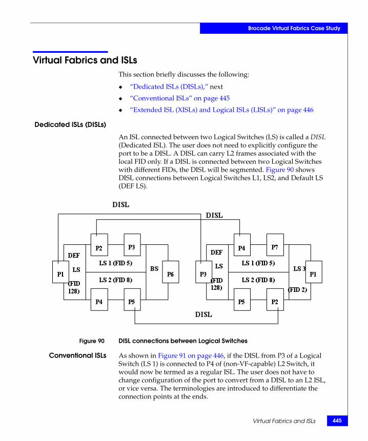
Brocade Virtual Fabrics Case Study
Virtual Fabrics and ISLsThis section briefly discusses the following:
◆ “Dedicated ISLs (DISLs),” next
◆ “Conventional ISLs” on page 445
◆ “Extended ISL (XISLs) and Logical ISLs (LISLs)” on page 446
Dedicated ISLs (DISLs)
An ISL connected between two Logical Switches (LS) is called a DISL (Dedicated ISL). The user does not need to explicitly configure the port to be a DISL. A DISL can carry L2 frames associated with the local FID only. If a DISL is connected between two Logical Switches with different FIDs, the DISL will be segmented. Figure 90 shows DISL connections between Logical Switches L1, LS2, and Default LS (DEF LS).
Figure 90 DISL connections between Logical Switches
Conventional ISLs As shown in Figure 91 on page 446, if the DISL from P3 of a Logical Switch (LS 1) is connected to P4 of (non-VF-capable) L2 Switch, it would now be termed as a regular ISL. The user does not have to change configuration of the port to convert from a DISL to an L2 ISL, or vice versa. The terminologies are introduced to differentiate the connection points at the ends.
Virtual Fabrics and ISLs 445
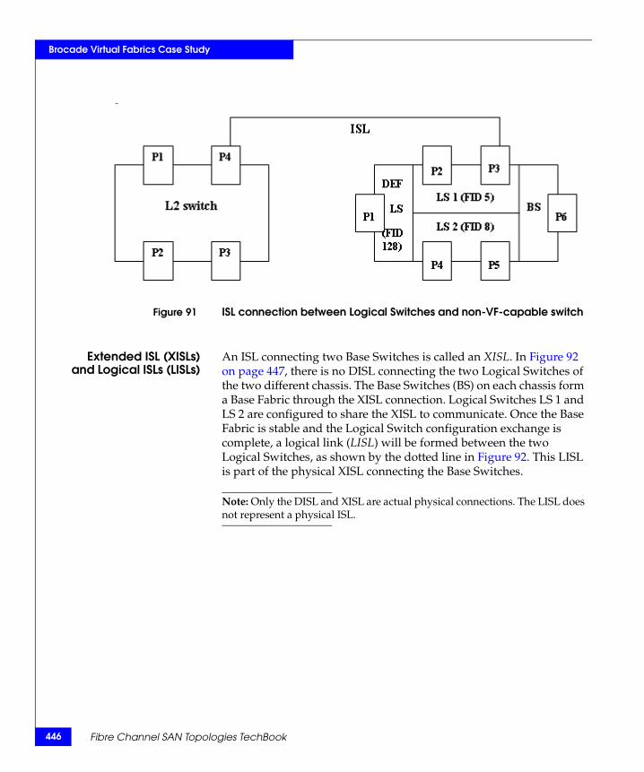
446
Brocade Virtual Fabrics Case Study
Figure 91 ISL connection between Logical Switches and non-VF-capable switch
Extended ISL (XISLs)and Logical ISLs (LISLs)
An ISL connecting two Base Switches is called an XISL. In Figure 92 on page 447, there is no DISL connecting the two Logical Switches of the two different chassis. The Base Switches (BS) on each chassis form a Base Fabric through the XISL connection. Logical Switches LS 1 and LS 2 are configured to share the XISL to communicate. Once the Base Fabric is stable and the Logical Switch configuration exchange is complete, a logical link (LISL) will be formed between the two Logical Switches, as shown by the dotted line in Figure 92. This LISL is part of the physical XISL connecting the Base Switches.
Note: Only the DISL and XISL are actual physical connections. The LISL does not represent a physical ISL.
Fibre Channel SAN Topologies TechBook
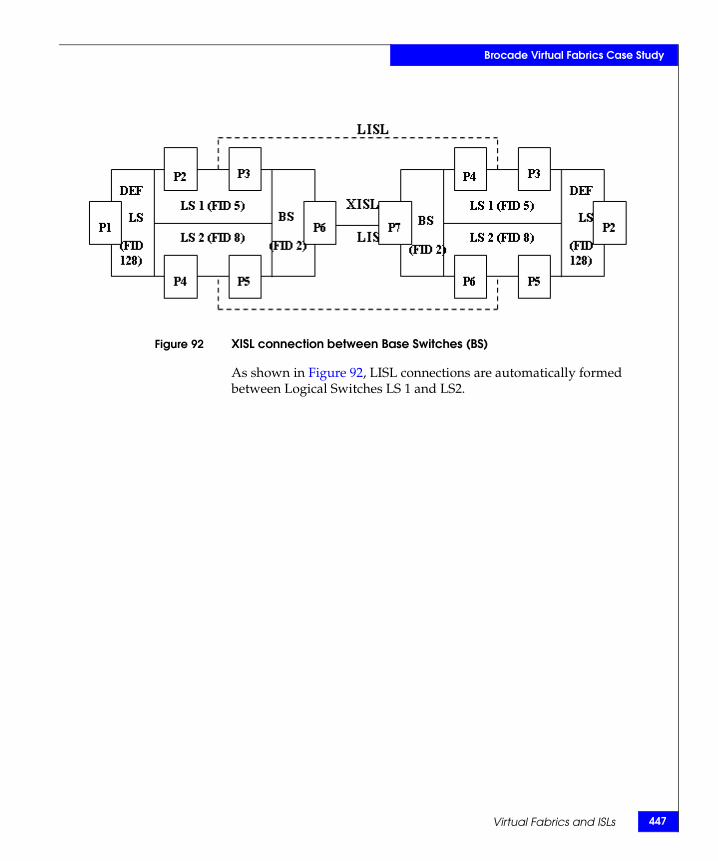
Brocade Virtual Fabrics Case Study
Figure 92 XISL connection between Base Switches (BS)
As shown in Figure 92, LISL connections are automatically formed between Logical Switches LS 1 and LS2.
Virtual Fabrics and ISLs 447
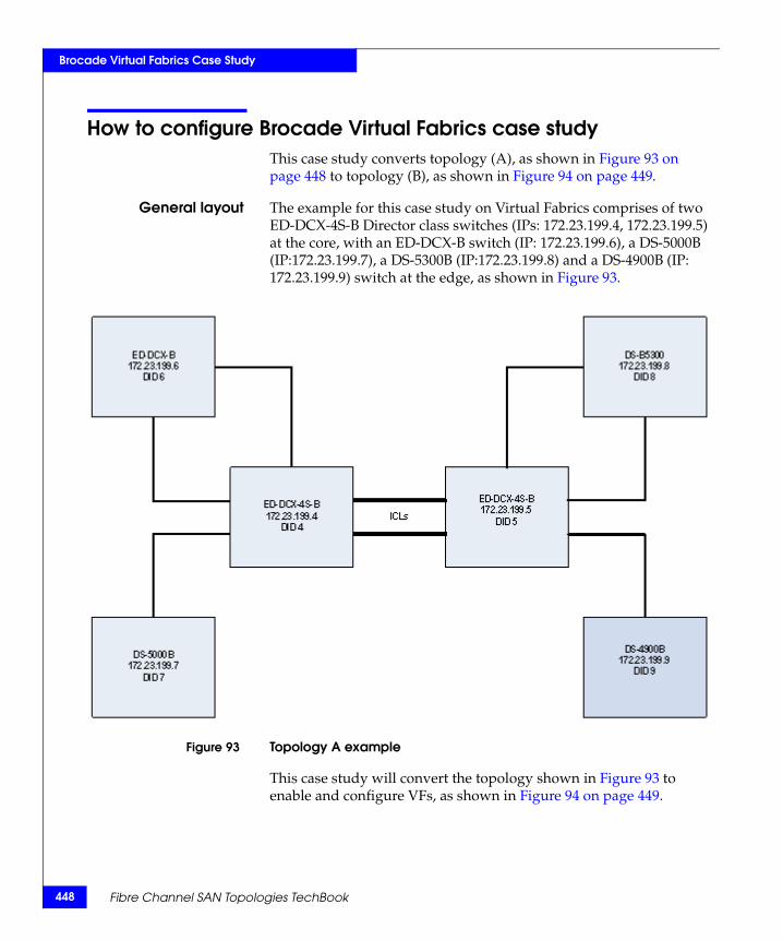
448
Brocade Virtual Fabrics Case Study
How to configure Brocade Virtual Fabrics case studyThis case study converts topology (A), as shown in Figure 93 on page 448 to topology (B), as shown in Figure 94 on page 449.
General layout The example for this case study on Virtual Fabrics comprises of two ED-DCX-4S-B Director class switches (IPs: 172.23.199.4, 172.23.199.5) at the core, with an ED-DCX-B switch (IP: 172.23.199.6), a DS-5000B (IP:172.23.199.7), a DS-5300B (IP:172.23.199.8) and a DS-4900B (IP: 172.23.199.9) switch at the edge, as shown in Figure 93.
Figure 93 Topology A example
This case study will convert the topology shown in Figure 93 to enable and configure VFs, as shown in Figure 94 on page 449.
Fibre Channel SAN Topologies TechBook
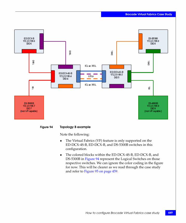
Brocade Virtual Fabrics Case Study
Figure 94 Topology B example
Note the following:
◆ The Virtual Fabrics (VF) feature is only supported on the ED-DCX-4S-B, ED-DCX-B, and DS-5300B switches in this configuration.
◆ The colored blocks within the ED-DCX-4S-B, ED-DCX-B, and DS-5300B in Figure 94 represent the Logical Switches on those respective switches. We can ignore the color coding in the figure for now. This will be clearer as we read through the case study and refer to Figure 95 on page 459.
How to configure Brocade Virtual Fabrics case study 449
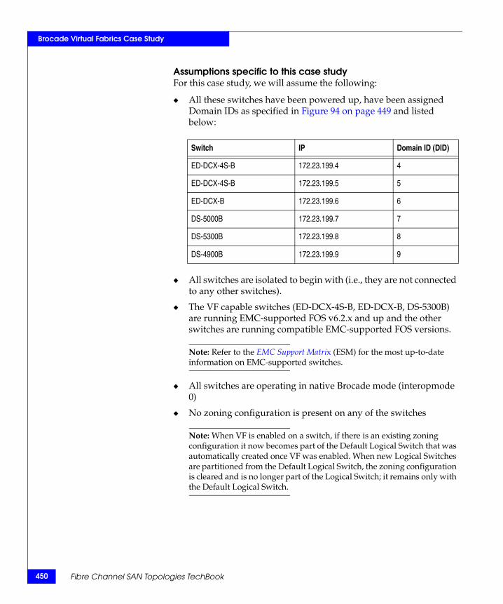
450
Brocade Virtual Fabrics Case Study
Assumptions specific to this case studyFor this case study, we will assume the following:
◆ All these switches have been powered up, have been assigned Domain IDs as specified in Figure 94 on page 449 and listed below:
◆ All switches are isolated to begin with (i.e., they are not connected to any other switches).
◆ The VF capable switches (ED-DCX-4S-B, ED-DCX-B, DS-5300B) are running EMC-supported FOS v6.2.x and up and the other switches are running compatible EMC-supported FOS versions.
Note: Refer to the EMC Support Matrix (ESM) for the most up-to-date information on EMC-supported switches.
◆ All switches are operating in native Brocade mode (interopmode 0)
◆ No zoning configuration is present on any of the switches
Note: When VF is enabled on a switch, if there is an existing zoning configuration it now becomes part of the Default Logical Switch that was automatically created once VF was enabled. When new Logical Switches are partitioned from the Default Logical Switch, the zoning configuration is cleared and is no longer part of the Logical Switch; it remains only with the Default Logical Switch.
Switch IP Domain ID (DID)
ED-DCX-4S-B 172.23.199.4 4
ED-DCX-4S-B 172.23.199.5 5
ED-DCX-B 172.23.199.6 6
DS-5000B 172.23.199.7 7
DS-5300B 172.23.199.8 8
DS-4900B 172.23.199.9 9
Fibre Channel SAN Topologies TechBook
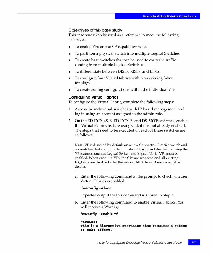
Brocade Virtual Fabrics Case Study
Objectives of this case studyThis case study can be used as a reference to meet the following objectives:
◆ To enable VFs on the VF-capable switches
◆ To partition a physical switch into multiple Logical Switches
◆ To create base switches that can be used to carry the traffic coming from multiple Logical Switches
◆ To differentiate between DISLs, XISLs, and LISLs
◆ To configure four Virtual fabrics within an existing fabric topology
◆ To create zoning configurations within the individual VFs
Configuring Virtual FabricsTo configure the Virtual Fabric, complete the following steps:
1. Access the individual switches with IP-based management and log in using an account assigned to the admin role.
2. On the ED-DCX-4S-B, ED-DCX-B, and DS-5300B switches, enable the Virtual Fabrics feature using CLI, if it is not already enabled. The steps that need to be executed on each of these switches are as follows:
Note: VF is disabled by default on a new Connectrix B series switch and on switches that are upgraded to Fabric OS 6.2.0 or later. Before using the VF features, such as Logical Switch and logical fabric, VFs must be enabled. When enabling VFs, the CPs are rebooted and all existing EX_Ports are disabled after the reboot. All Admin Domains must be deleted.
a. Enter the following command at the prompt to check whether Virtual Fabrics is enabled:
fosconfig --show
Expected output for this command is shown in Step c.
b. Enter the following command to enable Virtual Fabrics. You will receive a Warning.
fosconfig --enable vf
Warning!This is a disruptive operation that requires a reboot to take effect.
How to configure Brocade Virtual Fabrics case study 451
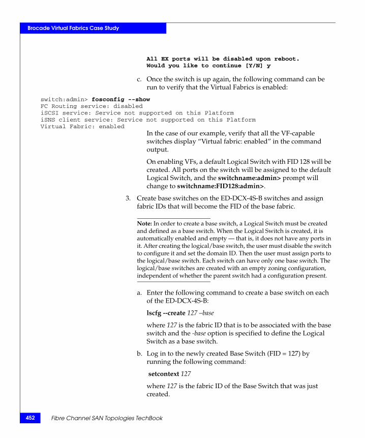
452
Brocade Virtual Fabrics Case Study
All EX ports will be disabled upon reboot.Would you like to continue [Y/N] y
c. Once the switch is up again, the following command can be run to verify that the Virtual Fabrics is enabled:
switch:admin> fosconfig --showFC Routing service: disablediSCSI service: Service not supported on this PlatformiSNS client service: Service not supported on this PlatformVirtual Fabric: enabled
In the case of our example, verify that all the VF-capable switches display “Virtual fabric: enabled” in the command output.
On enabling VFs, a default Logical Switch with FID 128 will be created. All ports on the switch will be assigned to the default Logical Switch, and the switchname:admin> prompt will change to switchname:FID128:admin>.
3. Create base switches on the ED-DCX-4S-B switches and assign fabric IDs that will become the FID of the base fabric.
Note: In order to create a base switch, a Logical Switch must be created and defined as a base switch. When the Logical Switch is created, it is automatically enabled and empty — that is, it does not have any ports in it. After creating the logical/base switch, the user must disable the switch to configure it and set the domain ID. Then the user must assign ports to the logical/base switch. Each switch can have only one base switch. The logical/base switches are created with an empty zoning configuration, independent of whether the parent switch had a configuration present.
a. Enter the following command to create a base switch on each of the ED-DCX-4S-B:
lscfg --create 127 –base
where 127 is the fabric ID that is to be associated with the base switch and the -base option is specified to define the Logical Switch as a base switch.
b. Log in to the newly created Base Switch (FID = 127) by running the following command:
setcontext 127
where 127 is the fabric ID of the Base Switch that was just created.
Fibre Channel SAN Topologies TechBook
Brocade Virtual Fabrics Case Study
c. Disable the base switch.
switchdisable
d. Configure the switch attributes, including assigning a unique domain ID by running the following command
configure
– Enter y at the Fabric Parameters prompt.
Note: As a best practice and for ease of management, EMC recommends that the user enters the domain ID of the parent switch from which the Logical Switch is being created. That way, if VFs are being created within an existing fabric, there is no possibility of any domain conflicts occurring within a Virtual Fabric.
– Enter 4 for ED-DCX-4S-B with DID:4 and enter 5 for ED-DCX-4S-B with DID:5 at the Domain ID prompt
– All other attributes can stay at the default values, including "Allow XISL use," which is set to "yes" by default.
– Ctrl D can be used to save changes and exit from this menu.
e. Enable the base switch by running the following command:
switchenable
f. Both base switches on the different physical switches will come up with the same default name. The user can change the name of these base switches by running the following command:
switchname bsname
where bsname specifies the name assigned to the base switch by the user.
Base switches with FID:127 and user defined Domain IDs and switch names have now been created and enabled on the ED- DCX-4S-B switches in this configuration.
4. Ports can now be assigned to the base switches that were created in Step 3. For this example, we intend to use ICL connections between the base switches, so we will add the ICL ports on each of the ED-DCX-4S-B chassis to the respective base switches.
How to configure Brocade Virtual Fabrics case study 453
454
Brocade Virtual Fabrics Case Study
Note: All ports on the chassis, including the ICL ports, are initially assigned to the default logical switch (FID 128). If ICLs are being deployed in the base switch, then all ports associated with those ICLs must be assigned to the base switch.
a. On each of the two ED-DCX-4S-B prompts the context must be set to the default Logical Switch to which the ICL ports are currently assigned. For our example, we will run the following command:
setcontext 128
where 128 is the fabric ID of the default Logical Switch where the ICL ports are currently present.
b. On each of the two switches, enter the following command to assign ports to the base switches:
lscfg --config 127 -slot 3 -port 0-15 (press enter and enter y at the prompt)
lscfg --config 127 -slot 6 -port 0-15
where 127 is the fabric ID of the base switch to which the ports are to be assigned, 3 and 6 are the slot numbers with the ICL ports, and 0-15 is the port range of ICL ports to be assigned to the base switch. If the -port option is omitted, all ports on the specified slot are automatically assigned to the logical/base switch.
The ICL ports are automatically disabled, then removed, from their current Logical Switches and assigned to the base switches specified by FID 127.
5. Physically connect the ICL ports between the base switches in the ED-DCX-4S-B chassis These ICL connections form XISLs, which are capable of routing traffic coming from different Logical Switches that will be created on the ED-DCX-4S-B classes
6. Enable all of the base switches by enabling the disabled ICL ports that are in the base switch.
a. On both the ED-DCX-4S-B prompts the context must be set to the base switch to which the ICL ports have been assigned. For our example we will run the following command:
setcontext 127
Fibre Channel SAN Topologies TechBook
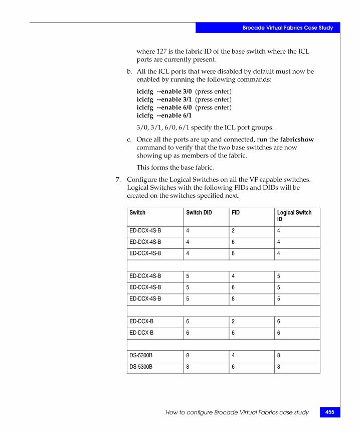
Brocade Virtual Fabrics Case Study
where 127 is the fabric ID of the base switch where the ICL ports are currently present.
b. All the ICL ports that were disabled by default must now be enabled by running the following commands:
iclcfg --enable 3/0 (press enter)iclcfg --enable 3/1 (press enter)iclcfg --enable 6/0 (press enter)iclcfg --enable 6/1
3/0, 3/1, 6/0, 6/1 specify the ICL port groups.
c. Once all the ports are up and connected, run the fabricshow command to verify that the two base switches are now showing up as members of the fabric.
This forms the base fabric.
7. Configure the Logical Switches on all the VF capable switches. Logical Switches with the following FIDs and DIDs will be created on the switches specified next:
Switch Switch DID FID Logical Switch ID
ED-DCX-4S-B 4 2 4
ED-DCX-4S-B 4 6 4
ED-DCX-4S-B 4 8 4
ED-DCX-4S-B 5 4 5
ED-DCX-4S-B 5 6 5
ED-DCX-4S-B 5 8 5
ED-DCX-B 6 2 6
ED-DCX-B 6 6 6
DS-5300B 8 4 8
DS-5300B 8 6 8
How to configure Brocade Virtual Fabrics case study 455
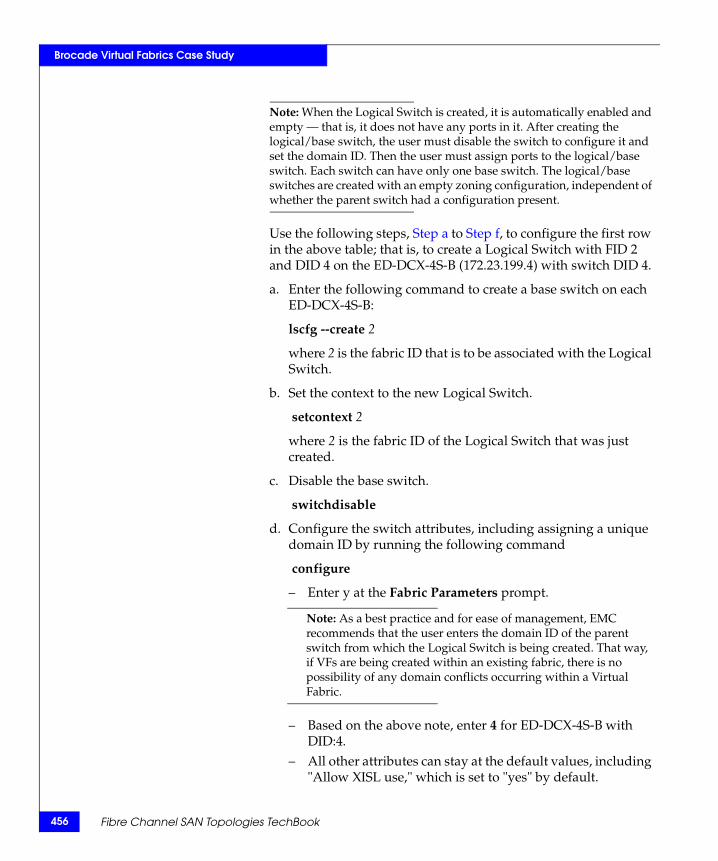
456
Brocade Virtual Fabrics Case Study
Note: When the Logical Switch is created, it is automatically enabled and empty — that is, it does not have any ports in it. After creating the logical/base switch, the user must disable the switch to configure it and set the domain ID. Then the user must assign ports to the logical/base switch. Each switch can have only one base switch. The logical/base switches are created with an empty zoning configuration, independent of whether the parent switch had a configuration present.
Use the following steps, Step a to Step f, to configure the first row in the above table; that is, to create a Logical Switch with FID 2 and DID 4 on the ED-DCX-4S-B (172.23.199.4) with switch DID 4.
a. Enter the following command to create a base switch on each ED-DCX-4S-B:
lscfg --create 2
where 2 is the fabric ID that is to be associated with the Logical Switch.
b. Set the context to the new Logical Switch.
setcontext 2
where 2 is the fabric ID of the Logical Switch that was just created.
c. Disable the base switch.
switchdisable
d. Configure the switch attributes, including assigning a unique domain ID by running the following command
configure
– Enter y at the Fabric Parameters prompt.
Note: As a best practice and for ease of management, EMC recommends that the user enters the domain ID of the parent switch from which the Logical Switch is being created. That way, if VFs are being created within an existing fabric, there is no possibility of any domain conflicts occurring within a Virtual Fabric.
– Based on the above note, enter 4 for ED-DCX-4S-B with DID:4.
– All other attributes can stay at the default values, including "Allow XISL use," which is set to "yes" by default.
Fibre Channel SAN Topologies TechBook
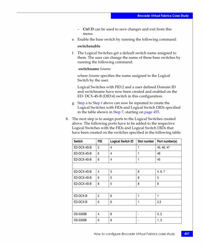
Brocade Virtual Fabrics Case Study
– Ctrl D can be used to save changes and exit from this menu.
e. Enable the base switch by running the following command:
switchenable
f. The Logical Switches get a default switch name assigned to them. The user can change the name of these base switches by running the following command:
switchname lsname
where lsname specifies the name assigned to the Logical Switch by the user.
Logical Switches with FID:2 and a user defined Domain ID and switchname have now been created and enabled on the ED- DCX-4S-B (DID:4) switch in this configuration.
g. Step a to Step f above can now be repeated to create the Logical Switches with FIDs and Logical Switch DIDs specified in the table shown in Step 7, starting on page 455.
8. The next step is to assign ports to the Logical Switches created above. The following ports have to be added to the respective Logical Switches with the FIDs and Logical Switch DIDs that have been created on the switches specified in the following table:
Switch FID Logical Switch ID Slot number Port number(s)
ED-DCX-4S-B 2 4 1 45, 46, 47
ED-DCX-4S-B 6 4 1 48
ED-DCX-4S-B 8 4 1 45
ED-DCX-4S-B 4 5 8 4. 6. 7
ED-DCX-4S-B 6 5 8 5
ED-DCX-4S-B 8 5 8 8
ED-DCX-B 2 6 1 1
ED-DCX-B 6 6 1 2,3
DS-5300B 4 8 - 0, 2
DS-5300B 6 8 - 1, 3
How to configure Brocade Virtual Fabrics case study 457

458
Brocade Virtual Fabrics Case Study
Use the following steps s to configure the first row in the above table above; that is, to add ports 1/44, 1/46, 1/47 to the Logical Switch with FID 2 and DID 4 on the ED-DCX-4S-B (172.23.199.4) with switch DID 4.
a. On the ED-DCX-4S-B (DID 4) prompt, the context must be set to the default Logical Switch to which the ports 1/44, 1/46, 1/47 are currently assigned. For our example, we will run the following command:
setcontext 128
where 128 is the fabric ID of the default Logical Switch where the ICL ports are currently present.
b. Enter the following command to assign ports to the base switch:
lscfg --config 2 -slot 1 -port 44 (press Enter and enter y at the prompt)
lscfg --config 2 -slot 1 -port 46-47
where 2 is the fabric ID of the base switch to which the ports are to be assigned, 1 if for the slot numbers with the desired ports, and 44, 45, and 46 is the port range of the ports to be assigned to the Logical Switch. If the -port option is omitted, all ports on the specified slot are automatically assigned to the logical/base switch.
The specified ports are automatically disabled, then removed, from their current Logical Switches and assigned to the base switches specified by FID 2.
c. Step a to Step b above can now be repeated to add the desired ports to the Logical Switches with FIDs and Logical Switch DIDs specified in the table shown in Step 8, starting on page 457.
Fibre Channel SAN Topologies TechBook
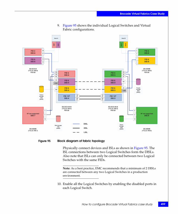
Brocade Virtual Fabrics Case Study
9. Figure 95 shows the individual Logical Switches and Virtual Fabric configurations.
Figure 95 Block diagram of fabric topology
Physically connect devices and ISLs as shown in Figure 95. The ISL connections between two Logical Switches form the DISLs. Also note that ISLs can only be connected between two Logical Switches with the same FIDs.
Note: As a best practice, EMC recommends that a minimum of 2 DISLs are connected between any two Logical Switches in a production environment.
10. Enable all the Logical Switches by enabling the disabled ports in each Logical Switch.
FID 4DID:5
FID 8DID:5
FID 6DID:5
FID 127DID:5
FID 2DID:4
FID 8DID:4
FID 6DID:4
FID 127DID:4
VF not supportedDID:7
FID 2DID:6
FID 8DID:6
FID 4DID:8
FID 6DID:8
VF not supportedDID:9
1/0
1/2
1/44
1/45
1/46
1/47
8
9
8/4
8/6
8/7
8/5
3/03/16/06/1
3/03/16/06/1
0
1
8
9
-1/288
-1/289
1/1
1/3
2
3
10 10
Host A
300F
828C
Host B
DFA
1
DFA
5
Yellowstorage
7FA(AD59)
ED-DCX-B (172.23.199.6)
FID128
ED-DCX-4S-B (172.23.199.4)
FID128
ED-DCX-4S-B (172.23.199.5)
FID128
DS-5000B (172.23.199.7)
DS-4900B (172.23.199.9)
DS-5300B (172.23.199.8)
FID128
DISL
XISL
LISL
1/48
8/8
Purple storage
9FA(AD63)
Greenstorage
9FB(AD64)
Red storage7FB
(AD60)
How to configure Brocade Virtual Fabrics case study 459
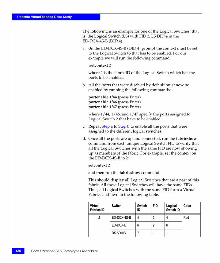
460
Brocade Virtual Fabrics Case Study
The following is an example for one of the Logical Switches, that is, the Logical Switch (LS) with FID 2, LS DID 4 in the ED-DCX-4S-B (DID 4).
a. On the ED-DCX-4S-B (DID 4) prompt the context must be set to the Logical Switch to that has to be enabled. For our example we will run the following command:
setcontext 2
where 2 is the fabric ID of the Logical Switch which has the ports to be enabled.
b. All the ports that were disabled by default must now be enabled by running the following commands:
portenable 1/44 (press Enter)portenable 1/46 (press Enter)portenable 1/47 (press Enter)
where 1/44, 1/46, and 1/47 specify the ports assigned to Logical Switch 2 that have to be enabled.
c. Repeat Step a to Step b to enable all the ports that were assigned to the different logical switches.
d. Once all the ports are up and connected, run the fabricshow command from each unique Logical Switch FID to verify that all the Logical Switches with the same FID are now showing up as members of the fabric. For example, set the context on the ED-DCX-4S-B to 2:
setcontext 2
and then run the fabricshow command.
This should display all Logical Switches that are a part of this fabric. All these Logical Switches will have the same FIDs. Thus, all Logical Switches with the same FID form a Virtual Fabric, as shown in the following table.
Virtual Fabrics ID
Switch Switch ID
FID Logical Switch ID
Color
2 ED-DCX-4S-B 4 2 4 Red
ED-DCX-B 6 2 6
DS-5000B 7 - -
Fibre Channel SAN Topologies TechBook
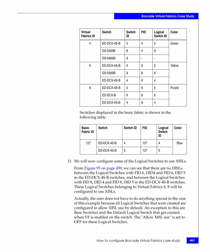
Brocade Virtual Fabrics Case Study
Switches displayed in the basic fabric is shown in the following table.
11. We will now configure some of the Logical Switches to use XISLs.
From Figure 95 on page 459, we can see that there are no DISLs between the Logical Switches with FID 6, DID4 and FID 6, DID 5 in the ED-DCX-4S-B switches, and between the Logical Switches with FID 8, DID 4 and FID 8, DID 5 in the ED-DCX-4S-B switches. These Logical Switches belonging to Virtual Fabrics 6, 8 will be configured to use XISLs.
Actually, the user does not have to do anything special in the case of this example because all Logical Switches that were created are configured to allow XISL use by default. An exception to this are Base Switches and the Default Logical Switch that get created when VF is enabled on the switch. The "Allow XISL use" is set to OFF for these Logical Switches.
4 ED-DCX-4S-B 5 4 5 Green
DS-5300B 8 4 8
DS-4900B 9 - -
6 ED-DCX-4S-B 5 6 5 Yellow
DS-5300B 8 6 8
ED-DCX-4S-B 4 6 4
8 ED-DCX-4S-B 5 8 5 Purple
ED-DCX-B 6 8 6
ED-DCX-4S-B 4 8 4
Basic Fabric ID
Switch Switch ID FID Logical Switch ID
Color
127 ED-DCX-4S-B 4 127 4 Blue
ED-DCX-4S-B 5 127 5
Virtual Fabrics ID
Switch Switch ID
FID Logical Switch ID
Color
How to configure Brocade Virtual Fabrics case study 461

462
Brocade Virtual Fabrics Case Study
This can be verified by running the switchshow command on every Logical Switch and validating that the "Allow XISL use" attribute is set to ON.
Note: If Logical Switches have the option to use either a DISL or the XISL, they will use the DISL to route traffic, since it is a lower cost path as compared to an XISL. The Logical Switch will always look for DISLs first to route the traffic to another Logical Switch in the same Virtual Fabric.
If the "Allow XISL use" attribute is set to OFF, complete the following steps:
a. Disable the base switch.
switchdisable
b. Configure the switch attributes by running the following command
configure
c. Enter y at the Fabric Parameters prompt.
d. Press Enter at the Domain ID prompt and enter y at Allow XISL use prompt.
e. All other attributes can stay at their default values.
f. Ctrl D can be used to save changes and exit from this menu.
Note: Every Logical Switch in the Virtual Fabric where XISLs are being used must have XISL use enabled.This must be set on every individual switch in the fabric. It is not a fabric-wide enabled feature.
For our example, since only Logical Switches with FID 6 and FID 8 will actually be using the XISLs, a switchshow on the Logical Switch with FID 8, DID 4 will display a logical E_Port with -1 for the slot and a virtual port number 289 for the slot port. Similarly, a switchshow on the Logical Switch with FID 6, DID 5 will display a logical E_Port with -1 for the slot and a virtual port number 288 for the slot port. This is an implication that this Logical Switch is using XISLs to rout traffic.
Fibre Channel SAN Topologies TechBook
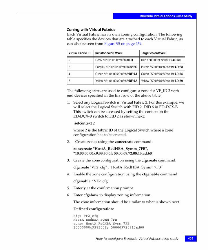
Brocade Virtual Fabrics Case Study
Zoning with Virtual FabricsEach Virtual Fabric has its own zoning configuration. The following table specifies the devices that are attached to each Virtual Fabric, as can also be seen from Figure 95 on page 459.
The following steps are used to configure a zone for VF_ID 2 with end devices specified in the first row of the above table.
1. Select any Logical Switch in Virtual Fabric 2. For this example, we will select the Logical Switch with FID 2, DID 6 in ED-DCX-B. This switch can be accessed by setting the context on the ED-DCX-B switch to FID 2 as shown next:
setcontext 2
where 2 is the fabric ID of the Logical Switch where a zone configuration has to be created.
2. Create zones using the zonecreate command:
zonecreate "HostA_RedHBA_Symm_7FB", "10:00:00:00:c9:38:30:0f; 50:00:09:72:08:13:ad:60"
3. Create the zone configuration using the cfgcreate command:
cfgcreate "VF2_cfg" , "HostA_RedHBA_Symm_7FB”
4. Enable the zone configuration using the cfgenable command.
cfgenable "VF2_cfg"
5. Enter y at the confirmation prompt.
6. Enter cfgshow to display zoning information.
The zone information should be similar to what is shown next.
Defined configuration:
cfg: VF2_cfgHostA_RedHBA_Symm_7FBzone: HostA_RedHBA_Symm_7FB10000000c938300f; 500009720813ad60
Virtual Fabric ID Initiator color/ WWN Target color/WWN
2 Red / 10:00:00:00:c9:38:30:0f Red / 50:00:09:72:08:13:AD:60
8 Purple / 10:00:00:00:c9:38:82:8C Purple / 50:06:04:82:cc:19:AD:63
4 Green / 21:01:00:e0:c8:b8:DF:A1 Green / 50:06:04:82:cc:19:AD:64
6 Yellow / 21:01:00:e0:c8:b8:DF:A5 Yellow / 50:06:04:82:cc:19:AD:59
How to configure Brocade Virtual Fabrics case study 463
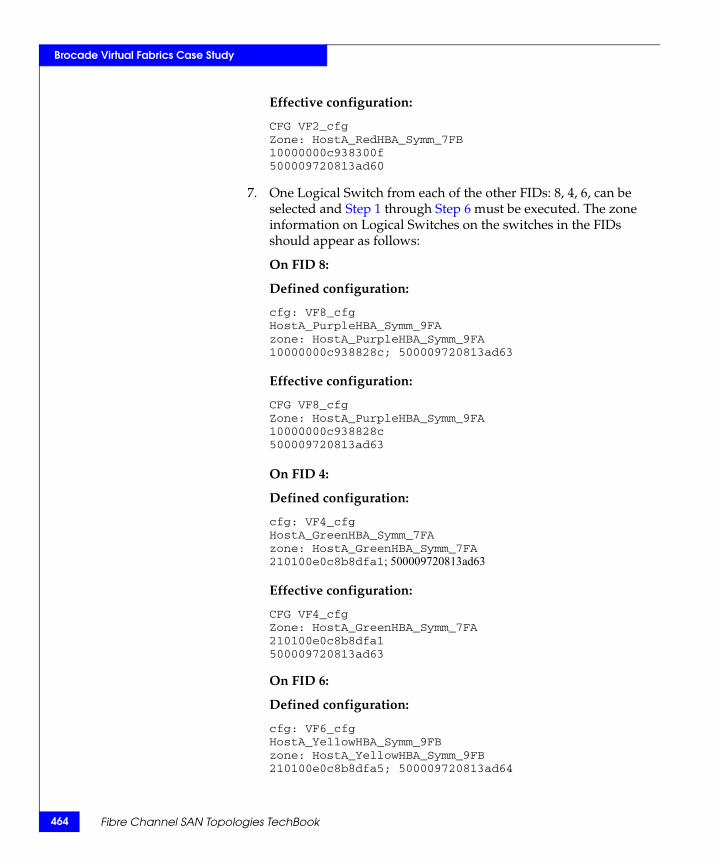
464
Brocade Virtual Fabrics Case Study
Effective configuration:
CFG VF2_cfgZone: HostA_RedHBA_Symm_7FB10000000c938300f 500009720813ad60
7. One Logical Switch from each of the other FIDs: 8, 4, 6, can be selected and Step 1 through Step 6 must be executed. The zone information on Logical Switches on the switches in the FIDs should appear as follows:
On FID 8:
Defined configuration:
cfg: VF8_cfgHostA_PurpleHBA_Symm_9FAzone: HostA_PurpleHBA_Symm_9FA10000000c938828c; 500009720813ad63
Effective configuration:
CFG VF8_cfgZone: HostA_PurpleHBA_Symm_9FA10000000c938828c 500009720813ad63
On FID 4:
Defined configuration:
cfg: VF4_cfgHostA_GreenHBA_Symm_7FAzone: HostA_GreenHBA_Symm_7FA210100e0c8b8dfa1; 500009720813ad63
Effective configuration:
CFG VF4_cfgZone: HostA_GreenHBA_Symm_7FA210100e0c8b8dfa1 500009720813ad63
On FID 6:
Defined configuration:
cfg: VF6_cfgHostA_YellowHBA_Symm_9FBzone: HostA_YellowHBA_Symm_9FB210100e0c8b8dfa5; 500009720813ad64
Fibre Channel SAN Topologies TechBook
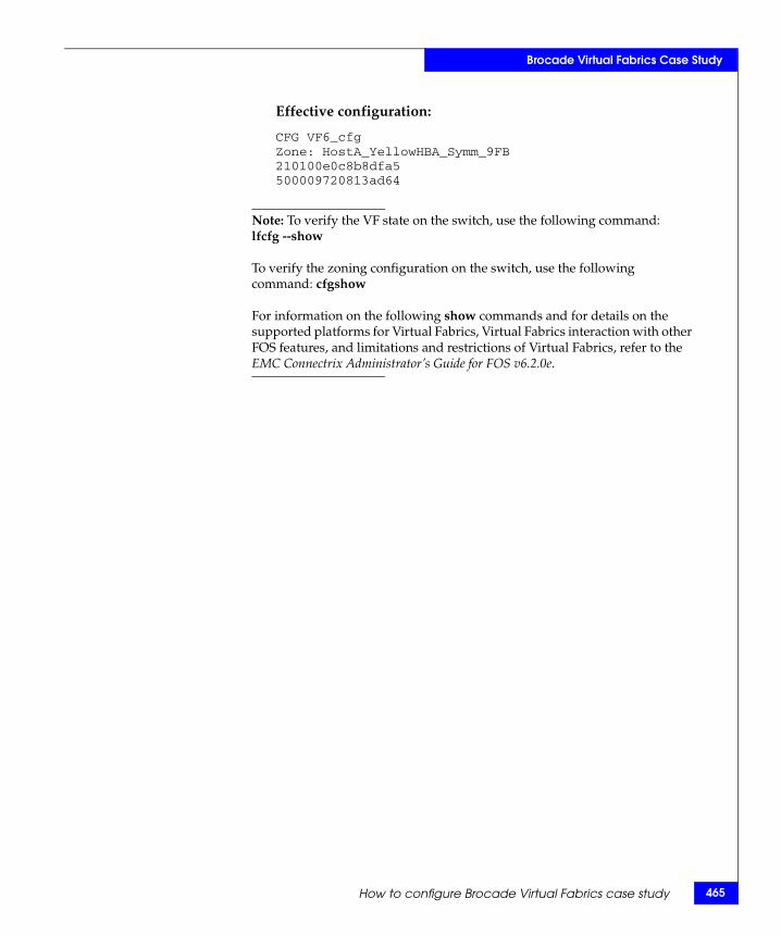
Brocade Virtual Fabrics Case Study
Effective configuration:
CFG VF6_cfgZone: HostA_YellowHBA_Symm_9FB210100e0c8b8dfa5 500009720813ad64
Note: To verify the VF state on the switch, use the following command: lfcfg --show
To verify the zoning configuration on the switch, use the following command: cfgshow
For information on the following show commands and for details on the supported platforms for Virtual Fabrics, Virtual Fabrics interaction with other FOS features, and limitations and restrictions of Virtual Fabrics, refer to the EMC Connectrix Administrator’s Guide for FOS v6.2.0e.
How to configure Brocade Virtual Fabrics case study 465
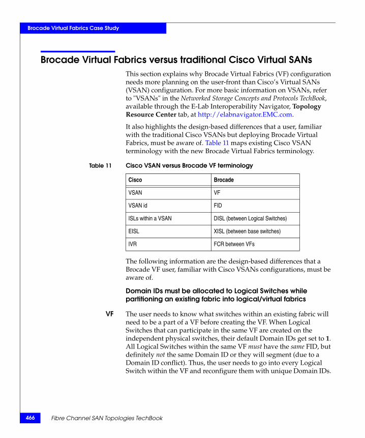
466
Brocade Virtual Fabrics Case Study
Brocade Virtual Fabrics versus traditional Cisco Virtual SANsThis section explains why Brocade Virtual Fabrics (VF) configuration needs more planning on the user-front than Cisco’s Virtual SANs (VSAN) configuration. For more basic information on VSANs, refer to "VSANs" in the Networked Storage Concepts and Protocols TechBook, available through the E-Lab Interoperability Navigator, Topology Resource Center tab, at http://elabnavigator.EMC.com.
It also highlights the design-based differences that a user, familiar with the traditional Cisco VSANs but deploying Brocade Virtual Fabrics, must be aware of. Table 11 maps existing Cisco VSAN terminology with the new Brocade Virtual Fabrics terminology.
The following information are the design-based differences that a Brocade VF user, familiar with Cisco VSANs configurations, must be aware of.
Domain IDs must be allocated to Logical Switches while partitioning an existing fabric into logical/virtual fabrics
VF The user needs to know what switches within an existing fabric will need to be a part of a VF before creating the VF. When Logical Switches that can participate in the same VF are created on the independent physical switches, their default Domain IDs get set to 1. All Logical Switches within the same VF must have the same FID, but definitely not the same Domain ID or they will segment (due to a Domain ID conflict). Thus, the user needs to go into every Logical Switch within the VF and reconfigure them with unique Domain IDs.
Table 11 Cisco VSAN versus Brocade VF terminology
Cisco Brocade
VSAN VF
VSAN id FID
ISLs within a VSAN DISL (between Logical Switches)
EISL XISL (between base switches)
IVR FCR between VFs
Fibre Channel SAN Topologies TechBook
Brocade Virtual Fabrics Case Study
VSAN This is not the case with Cisco VSANs. When VSANs get created, the switches that are participating in a VSAN retain their original Domain ID so the user does not have to reconfigure them.
Zoning information may be shared between Logical Switches, even when FIDs may not match
VF While creating a VF within an operational fabric, it is essential to verify that the E_Ports between Logical Switches (on different physical switches) being connected to each other have the same FID. If there is a mismatch between the FIDs, the management application will notify the user that the ISL was segmented due to an FID conflict. In case one of the segmented switches does not have an active zoning configuration, it will import the configuration from the switch it was linked to through ISLs. The reason for this is that when two Logical Switches are linked through ISLs, the following sequence of checks take place:
◆ Domain ID check.
◆ If the Domain ID check passes, then a zone check, operating mode, and FID check takes place. In most cases, the zone check takes place before the FID check. If one of the Logical Switches has no zone configuration, it pulls it from the other Logical Switch to which it is attached. It later segments due to an FID conflict (if the FIDs do not match). The user now needs to go into, and delete, the Logical Switch that imported the undesired zone configuration.
VSAN This is not the case with Cisco VSANs, which work by prepending a Virtual Fabric header tag onto each frame as it enters the switch, which indicates on which VSAN the frame arrived. This tag is subsequently used when the switch makes distributed hardware forwarding decisions. Cisco frame forwarding ASICs are Virtual Fabric-aware and use the industry-standard Virtual Fabric Trunking (VFT) extended headers in forwarding decisions, therefore would not allow any transactions between two switches that have ports belonging to different VSANs.
Switch name must be configured on the Logical Switches
VF When a Logical Switch (LS) is created on a switch, the new LS uses a default switch name. Therefore, in a given Virtual Fabric all Logical Switches will end up with the same switch name if the user does not redefine them. This has been purposely designed to provide flexibility to administrators (who may be using the different VFs), to
Brocade Virtual Fabrics versus traditional Cisco Virtual SANs 467

468
Brocade Virtual Fabrics Case Study
use their specific naming conventions within their VFs, rather than having to use a pre-defined switch name.
VSAN For Cisco switches, the default name is its IP address and this name, or the user-defined name, is retained even when its ports become a part of different VSANs. The user then has the ability to edit it, if desired.
Note: For users that may not expect the Logical Switch settings to go to a default value, (which addresses the configuration specifics discussed previously in this section), Brocade has added the following CLI warning message after a Logical Switch is created:
“Logical Switch has been created with default configurations. Please configure the Logical Switch with appropriate switch and protocol settings before activating the Logical Switch.”
Deleting a VF
VF If the user wants to delete a VF using Brocade CLI, the following two steps must be executed:
1. All the ports that are a part of the Logical Switches in that VF need to be transferred to the default Logical Switch (FID 128), or any other Logical Switch.
2. All the Logical Switches within the VF need to be individually deleted.
VSAN With the Cisco CLI, a VSAN can be deleted, which pulls out all the ports on that switch that were participating in the VSAN and automatically transfers them into the default VSAN (VSAN ID: 4094).
With Cisco Fabric Manager, once a VSAN is deleted all the ports under the participating switches in that VSAN get automatically transferred to the respective default VSANs on those physical switches.
Brocade “Base switches” concept
VF Brocade’s VF introduces the concept of a Base switch. A Base switch is a Logical Switch (LS) that comprises of E_Ports that can connect to ports in other base switches only, forming XISLs, which are capable of carrying traffic from multiple VFs. Therefore, for Brocade switches, the user has to create a base switch with the same FID on two switches that are a part of the same VF, rather than just configuring a port that is in the Default Logical Switch.
Fibre Channel SAN Topologies TechBook
Brocade Virtual Fabrics Case Study
VSAN For Cisco switches, ports that are not a part of any VSAN (on a switch with more than one VSAN) can be configured as TE_Ports (trunk E_Ports). When two TE_Ports are connected, they form an EISL. An EISL can carry traffic coming from multiple VSANs. The TE_Port does not need to be in any VSAN.
FCR with Brocade VFs
VF Brocade’s FCR technology can be used to route traffic between different VFs. A Base Switch in the fabric will be used for legacy FCR support. All EX_Ports need to be part of the Base Switch. The EX_Ports will be disabled if they are in non-base switch. “Extended ISL (XISLs) and Logical ISLs (LISLs)” on page 446 explained how a Base switch is created and can be connected to other Base Switches through a special XISL to form a Base Fabric. For FCR between VFs, users can view the base switch as a FCR-backbone switch and Base Fabric as FCR-backbone fabric (in Brocade FCR concept). The Base switches can have EX_Ports attached to E_Ports on the Logical Switches that are a part of different VFs with the end devices that have to communicate. Thus, the VFs form the edge fabrics. LSAN zones have to be created on the edge VFs (VFs with the end devices) so that the initiator on one VF can access the target in another VF.
VSAN Cisco IVRs allows data traffic to be transported between specific initiators and targets on different VSANs without merging the VSANs into a single logical fabric. IVR is not limited to VSANs present on a common switch. Routes that traverse one or more VSANs across multiple switches can be established, if necessary, to establish proper interconnections.
Brocade Virtual Fabrics versus traditional Cisco Virtual SANs 469

470
Brocade Virtual Fabrics Case Study
Fibre Channel SAN Topologies TechBook
6Invisible Body Tag
This chapter provides an EMC RecoverPoint case study with the AP-7600B application services platform. The following topics will be discussed:
◆ RecoverPoint case study overview................................................ 472◆ Implementing a scalable core-edge topology .............................. 554
EMC RecoverPointCase Study
EMC RecoverPoint Case Study 471
472
EMC RecoverPoint Case Study
RecoverPoint case study overviewThis section provides information for the following case study:
Case Study: RecoverPoint with AP-7600B application services platform
The following information is included:
◆ “Configuration overview” on page 472
◆ “RecoverPoint concepts” on page 474
◆ “RecoverPoint components” on page 475
◆ “RecoverPoint installation prerequisites” on page 477
◆ “Phase 1: Base configuration of Connectrix B series fabric” on page 486
◆ “Phase 2: Add and configure Connectrix AP-7600B application services platform” on page 487
◆ “Phase 3: Add second AP-7600B to Fabric B” on page 502
◆ “Phase 4: Add and configure RecoverPoint Appliance (RPA)” on page 503
◆ “Phase 5: Configure recovery site Connectrix AP-7600B and RPA” on page 524
◆ “Phase 6: Configure RecoverPoint volumes and services” on page 531
◆ “Phase 7: Start replication” on page 551
◆ “Phase 8: Confirm replication is running” on page 553
Configuration overviewA company has a set of mission-critical applications for which it needs to replicate data over between San Jose and San Diego, California. The company wants to install RecoverPoint to provide asynchronous replication of an application using a WAN connection between these two sites. The data center has a two-switch fabric using a DS-4100B and a DS-4900B. The recovery site has a single-switch fabric using a DS-4100B. The configuration has to be highly available.
RecoverPoint provides SAN-based data protection services including continuous data protection (CDP) and continuous remote replication
Fibre Channel SAN Topologies TechBook
EMC RecoverPoint Case Study
(CRR). Due to the distance involved, RecoverPoint will be configured for CRR (asynchronous writes). RecoverPoint uses an out-of-band RecoverPoint Appliance (RPA) that connects to an existing SAN fabric and controls a "write splitting" service. A fabric write split means the Data Path Controller (DPC) on the AP-7600B intercepts a host write and creates two writes, one going to the host's storage LUN and the second going to a local RecoverPoint appliance (RPA). The local RPA generates and manages a CRR (asynchronous) write to a second RPA (typically at the remote recovery site). The remote RPA then generates a write to remote storage. One application, SQLServer, will be replicated over the WAN. (Refer to “RecoverPoint concepts” on page 474 for more information about RecoverPoint and its capabilities.)
The configuration uses the Connectrix AP-7600B, 4 Gb/s Application Services Platform connected to an existing Connectrix B series two-switch fabric. The AP-7600B behaves as a Fibre Channel switch connecting to the existing fabric with E_Ports creating ISL connections (automatically creating ISL trunks when more than one ISL connects to the same fabric switch) and supports Frame Redirection so the existing physical initiator and target zones are not changed when adding RecoverPoint replication CRR (or CDP).
The AP-7600B includes two data path controllers (DPC). A DPC is capable of creating multiple virtual initiators (VI) and virtual targets (VT). The VI and VT are logical ports, each with its own world wide port names. Therefore, every VI/VT is accessible from any physical switch port on the AP-7600B and, via the AP-7600B ISL connections, from any other port in the fabric. Refer to the EMC Connectrix B Series AP-7600B Hardware Reference Manual located on Powerlink for more details about the AP-7600B.
The base configuration is an existing Connectrix B fabric (Interopmode 0). Mirrored fabrics are deployed, each with a two-switch mesh. Figure 96 on page 486 shows the connections for Fabric A and, for simplicity, only the device connections in Fabric B. The topology at the secondary site can be any suitable topology supported for Connectrix B series fabrics. In this example, it uses mirrored fabrics, each with a single DS-4100B switch. The specific configuration settings, best practices, host and storage layouts, and topology design for the two switch configuration are discussed in “Connectrix B example” on page 41.
The application being protected is a Microsoft SQL application using two LUNs, configured as Drive F and Drive G. Drive F holds log and
RecoverPoint case study overview 473
474
EMC RecoverPoint Case Study
journal files while Drive G holds the SQL database file. The RecoverPoint configuration uses consistency groups to ensure the order of the writes to these LUNs are preserved at the replication site.
Redundant WAN links are accessible from routers on an IP network with Gigabit Ethernet connections. Each WAN link is a DS-3 at 45 Mb/s, which is sufficient to handle the replication traffic taking advantage of the RPA compression capability.
RecoverPoint conceptsReplication volumes are defined at the source and destination site. These volumes contain the application data (source site) and replicated copy of that data (destination site). Replication volumes are associated with each other using replication pairs consisting of one replication volume at each site.
RecoverPoint replication uses a logical entity called a consistency group. (Refer to “Consistency group” on page 477 for more information.) One or more replication pairs are assigned to a consistency group. Data consistency and write-order fidelity are maintained across all volumes assigned to a consistency group, including volumes on different storage systems. RecoverPoint supports multiple consistency groups.
RecoverPoint is designed so that a cluster of RecoverPoint Appliances can be deployed to provide scalability and high availability. A failure of an RPA is non-disruptive to the application. As RPA nodes are added to a cluster, they are automatically discovered and IO is automatically load balanced over all the cluster nodes. Each node can support a maximum of 50 MB/s of write traffic.
When configured for CRR operation, an application host issues a SCSI write. This write is intercepted by the AP-7600B virtual target which splits the write into two writes. Both writes are sent out a virtual initiator bound to the host initiator. One write goes to the original storage LUN used by the application and the second to the target port of the local RPA. The RPA enters the write into the journal volume, compresses the data, and then forwards the write over the WAN link via the RPA initiator to the RPA cluster at the remote site. The write is received by the remote RPA on its target port and then written to the remote site journal volume using its initiator port and a status returned to the originating RPA cluster. The remote RPA then writes the data from the journal volume to the replication volume via its initiator port marking the journal volume entry as completed.
Fibre Channel SAN Topologies TechBook
EMC RecoverPoint Case Study
RecoverPoint components
Data path controllerInside the AP-7600B each port contains a data path controller which can be configured as a virtual target, virtual initiator or both. Separate WWPNs are assigned to the virtual initiator and virtual targets. Once Frame Redirect is enabled on the AP-7600B, traffic is automatically routed through the VT/VI combination with no zoning changes required.
Host initiator to virtual initiator bindingApplication traffic has to flow between the two SCSI nexus created by the DPCs in an AP-7600B. A host initiator-to-virtual initiator mapping defines how traffic from a physical host flows to the corresponding virtual initiator port. This provides consistent SCSI reservation management across the two SCSI nexus. This mapping is done automatically by the AP-7600B when a host initiator is bound to a physical storage port.
Virtual initiatorA single virtual initiator is available per DPC.
Virtual targetAlthough a DPC can create a virtual initiator and multiple virtual targets, the WWPN for each is different. When an initiator is bound to a physical target, the switch creates virtual targets and virtual initiators and handles the mapping automatically.
RecoverPoint agentThis is a software "shim" running on the AP-7600B that communicates with the RPA. Control path messages between the RPA and the AP-7600B are carried "in-band" over Fibre Channel.
RecoverPoint storage componentsA RecoverPoint solution uses SAN storage for its repository, journal, and remote replication volumes.
Repository volumeThis stores pertinent replication environment information and "bookmarks" for recovery point rollback. As part of the installation process, you must create a repository volume at both the source (San Jose) and destination (San Diego) sites. The repository volume should reside in a storage environment that guarantees high availability, and must be accessible to all RPAs at that site. A repository volume is visible only to the RPA at its site, not the RPA(s) at the remote site.
RecoverPoint case study overview 475
476
EMC RecoverPoint Case Study
Repository volumes may be created on the same SAN storage as the application's data. The recommended size is 2 GB per consistency group. In most cases, this is sufficient to support a week-long delay in transferring data from the source to the target site.
Journal volume This stores consistent point-in-time (PIT) images for the target site. There is at least one journal volume at each site per consistency group and they should be visible only to the RPA at that site. A journal volume can be maintained on one or more SAN storage volumes.
In configuring a consistency group, you must attach at least one journal volume at each site, to support failover. The minimum total size for the group’s journal at each site is 3.5 GB. The size is defined by how far back recovery should be possible. For example, if snapshots for a consistency group must be stored for 24 hours, the journal volume must be sized accordingly. A rule of thumb is to size the journal volume at 20% of the size of all data disks participating in replication.
The journal for each consistency group must be large enough to support your business requirements for that group. For instance, if your policy for a given consistency group requires the storing of all snapshots for the last 24-hour period, then the journal for that group must be at least as large as the amount of snapshot data that is likely to be written for that group in a complete day. Refer to the EMC RecoverPoint Installation Guide, located on Powerlink, for a Site Planning Sheet you can use to size your journals.
Replication volumeThis is the data volume for the application that is being replicated. Typically this LUN already exists at the source site. Creation of the source replication volume does not destroy data; it just associates the existing LUN with the replication process. Blue storage target LUNs 24 and 25 are the source LUNs that will be replicated to the recovery site. A destination replication volume is created at the recovery site on an existing, empty LUN and should be the same size as the source replication volume. Creation of the destination LUN does destroy data (if any) on that LUN. The maximum replication volume size supported is 1.99 TB.
Fibre Channel SAN Topologies TechBook
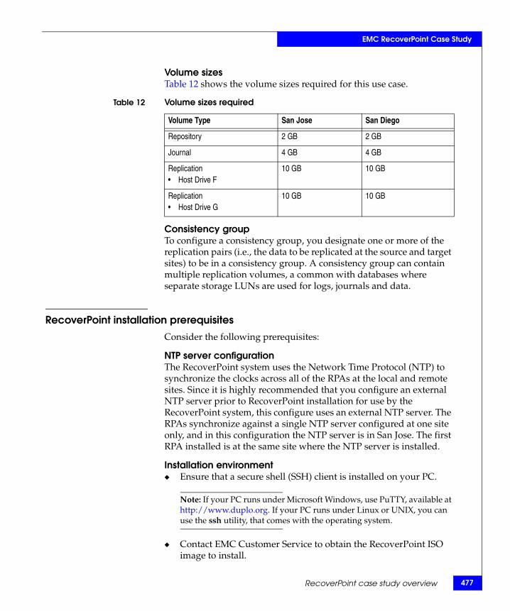
EMC RecoverPoint Case Study
Volume sizesTable 12 shows the volume sizes required for this use case.
Consistency groupTo configure a consistency group, you designate one or more of the replication pairs (i.e., the data to be replicated at the source and target sites) to be in a consistency group. A consistency group can contain multiple replication volumes, a common with databases where separate storage LUNs are used for logs, journals and data.
RecoverPoint installation prerequisitesConsider the following prerequisites:
NTP server configurationThe RecoverPoint system uses the Network Time Protocol (NTP) to synchronize the clocks across all of the RPAs at the local and remote sites. Since it is highly recommended that you configure an external NTP server prior to RecoverPoint installation for use by the RecoverPoint system, this configure uses an external NTP server. The RPAs synchronize against a single NTP server configured at one site only, and in this configuration the NTP server is in San Jose. The first RPA installed is at the same site where the NTP server is installed.
Installation environment◆ Ensure that a secure shell (SSH) client is installed on your PC.
Note: If your PC runs under Microsoft Windows, use PuTTY, available at http://www.duplo.org. If your PC runs under Linux or UNIX, you can use the ssh utility, that comes with the operating system.
◆ Contact EMC Customer Service to obtain the RecoverPoint ISO image to install.
Table 12 Volume sizes required
Volume Type San Jose San Diego
Repository 2 GB 2 GB
Journal 4 GB 4 GB
Replication • Host Drive F
10 GB 10 GB
Replication• Host Drive G
10 GB 10 GB
RecoverPoint case study overview 477
478
EMC RecoverPoint Case Study
◆ Burn the ISO image onto a CD.
◆ For remote installations, the most convenient procedure is to have the ISO image available on a local FTP server.
◆ Check the checksum of the RecoverPoint ISO image against the md5sum listed in Powerlink. If you are running Microsoft Windows, use the utility md5sum.exe, which is available at http://www.etree.org/md5com.html. Instructions are provided on the download page.
RecoverPoint interfacesThe following information describes the required EMC RecoverPoint interfaces for this typical configuration.
Fibre Channel
The RPAs connect to the hosts and storage subsystems via a Fibre Channel SAN. In preparation for RecoverPoint installation, ensure that there are four ports available within the Fibre Channel infrastructure for each RPA. Each RPA has two, dual-port HBAs. The top port of each HBA is used as an initiator and the bottom port is used as a target.
IP/Ethernet for WAN interface
RPAs are linked to the WAN via IP/Ethernet connection. The route via the IP network over the WAN from the RPAs at one site to the RPAs at the other site must be defined. In addition, sufficient WAN bandwidth must be available. WAN replication traffic consists of writes, not reads, which reduces the bandwidth required for replication. The rule of thumb for DBMS IO is that 20% of the IO is due to writes, which was used for this configuration. The availability of a DS-3, 45 Mb/s/s WAN link provides sufficient bandwidth for replication.
IP/Ethernet for Management interface
The management IP addresses for all RPAs at a site, and the virtual IP address used for site management, must all reside on the same subnet. This will be a different subnet from those used for the WAN interfaces.
Serial interface
For additional network redundancy, the serial interface to the RPAs may be accessed via a terminal server, standard desktop PC, or laptop.
Fibre Channel SAN Topologies TechBook
EMC RecoverPoint Case Study
Note: The serial interface is available for RPAs installed on an EMC-supported platform. In RecoverPoint 2.4, this is the Dell 1950.
AssumptionsThe following assumptions are specific to this use case:
◆ The Fibre Channel switches, AP-7600B, and RecoverPoint Appliance are installed in an EMC-supplied cabinet.
• For installation instructions, see Connectrix EC-1500 Cabinet Installation and Setup Manual which can be accessed from Powerlink.
◆ Redundant power sources are available.
• For switch power requirements, refer to Non-EMC Connectrix SAN Products Data Reference Manual, available through the E-Lab Interoperability Navigator, Topology Resource Center tab, at http://elabnavigator.EMC.com.
◆ A laptop is available with the following specifications:
• Running some version of Windows
• HyperTerminal is installed
• Laptop serial ports are DB-9 connections and COM1 will be used to configure the IP addresses
◆ Mirrored fabrics are deployed for high-availability at both the primary and recovery sites.
◆ EMC PowerPath® is deployed on hosts providing multi-path and path fail-over services.
◆ A serial cable (straight through) and Ethernet cable (crossover) are available.
◆ Network drops, IP addresses, subnet mask, and gateway have been provided by the customer. (See the “Customer site planning worksheet” on page 480.)
◆ SFP transceivers and compatible fiber cables are available as required.
◆ Access to an FTP server, for backing up (uploading) or downloading the switch configuration and for storing the RecoverPoint ISO image is available.
◆ License keys have been obtained.
RecoverPoint case study overview 479
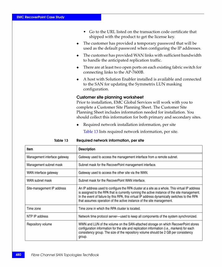
480
EMC RecoverPoint Case Study
• Go to the URL listed on the transaction code certificate that shipped with the product to get the license key.
◆ The customer has provided a temporary password that will be used as the default password when configuring the IP addresses.
◆ The customer has provided WAN links with sufficient bandwidth to handle the anticipated replication traffic.
◆ There are at least two open ports on each existing fabric switch for connecting links to the AP-7600B.
◆ A host with Solution Enabler installed is available and connected to the SAN for updating the Symmetrix LUN masking configuration.
Customer site planning worksheetPrior to installation, EMC Global Services will work with you to complete a Customer Site Planning Sheet. The Customer Site Planning Sheet includes information needed for installation. You should collect this information for both primary and secondary sites.
◆ Required network installation information, per site
Table 13 lists required network information, per site.
Table 13 Required network information, per site
Item Description
Management interface gateway Gateway used to access the management interface from a remote subnet.
Management subnet mask Subnet mask for the RecoverPoint management interface.
WAN interface gateway Gateway used to access the other site via the WAN.
WAN subnet mask Subnet mask for the RecoverPoint WAN interface.
Site-management IP address An IP address used to configure the RPA cluster at a site as a whole. This virtual IP address is assigned to the RPA that is currently running the active instance of the site management. In the event of failure by this RPA, this virtual IP address dynamically switches to the RPA that assumes operation of the active instance of the site management.
Time zone Time zone in which the RPA cluster is located.
NTP IP address Network time protocol server—used to keep all components of the system synchronized.
Repository volume WWN and LUN of the volume on the SAN-attached storage on which RecoverPoint stores configuration information for the site and replication information (i.e., markers) for each consistency group. The size of the repository volume should be 2 GB per consistency group.
Fibre Channel SAN Topologies TechBook
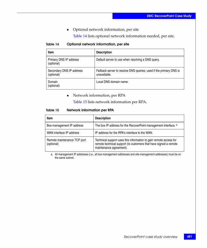
EMC RecoverPoint Case Study
◆ Optional network information, per site
Table 14 lists optional network information needed, per site.
◆ Network information, per RPA
Table 15 lists network information per RPA.
Table 14 Optional network information, per site
Item Description
Primary DNS IP address (optional)
Default server to use when resolving a DNS query.
Secondary DNS IP address(optional)
Failback server to resolve DNS queries; used if the primary DNS is unavailable.
Domain (optional)
Local DNS domain name.
Table 15 Network information per RPA
Item Description
Box-management IP address The box IP address for the RecoverPoint management interface. a
WAN interface IP address IP address for the RPA’s interface to the WAN.
Remote maintenance TCP port (optional)
Technical support uses this information to gain remote access for remote technical support (to customers that have signed a remote maintenance agreement).
a. All management IP addresses (i.e., all box-management addresses and site-management addresses) must be on the same subnet.
RecoverPoint case study overview 481
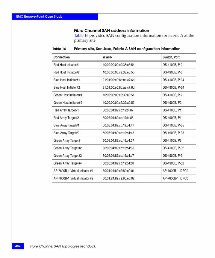
482
EMC RecoverPoint Case Study
Fibre Channel SAN address informationTable 16 provides SAN configuration information for Fabric A at the primary site.
Table 16 Primary site, San Jose, Fabric A SAN configuration information
Connection WWPN Switch, Port
Red Host Initiator#1 10:00:00:00:c9:38:e5:54 DS-4100B, P-0
Red Host Initiator#2 10:00:00:00:c9:38:e5:55 DS-4900B, P-0
Blue Host Initiator#1 21:01:00:e0:8b:8a:c7:6d DS-4100B, P-34
Blue Host Initiator#2 21:01:00:e0:8b:aa:c7:6d DS-4900B, P-34
Green Host Initiator#1 10:00:00:00:c9:39:a0:51 DS-4100B, P-2
Green Host Initiator#2 10:00:00:00:c9:39:a0:52 DS-4900B, P2
Red Array Target#1 50:06:04:82:cc:19:bf:87 DS-4100B, P1
Red Array Target#2 50:06:04:82:cc:19:bf:88 DS-4900B, P1
Blue Array Target#1 50:06:04:82:cc:19:c4:47 DS-4100B, P-35
Blue Array Target#2 50:06:04:82:cc:19:c4:48 DS-4900B, P-35
Green Array Target#1 50:06:04:82:cc:19:c4:07 DS-4100B, P3
Green Array Target#2 50:06:04:82:cc:19:c4:08 DS-4100B, P-32
Green Array Target#3 50:06:04:82:cc:19:c4:c7 DS-4900B, P-3
Green Array Target#4 50:06:04:82:cc:19:c4:c8 DS-4900B, P-32
AP-7600B-1 Virtual Initiator #1 60:01:24:82:c2:80:e0:01 AP-7600B-1, DPC0
AP-7600B-1 Virtual Initiator #2 60:01:24:82:c2:80:e0:02 AP-7600B-1, DPC0
Fibre Channel SAN Topologies TechBook
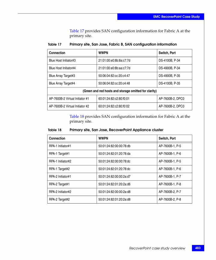
EMC RecoverPoint Case Study
Table 17 provides SAN configuration information for Fabric A at the primary site.
Table 18 provides SAN configuration information for Fabric A at the primary site.
Table 17 Primary site, San Jose, Fabric B, SAN configuration information
Connection WWPN Switch, Port
Blue Host Initiator#3 21:01:00:e0:8b:8a:c7:7d DS-4100B, P-34
Blue Host Initiator#4 21:01:00:e0:8b:aa:c7:7d DS-4900B, P-34
Blue Array Target#3 50:06:04:82:cc:20:c4:47 DS-4900B, P-35
Blue Array Target#4 50:06:04:82:cc:20:c4:48 DS-4100B, P-35
(Green and red hosts and storage omitted for clarity)
AP-7600B-2 Virtual Initiator #1 60:01:24:82:c2:80:f0:01 AP-7600B-2, DPC0
AP-7600B-2 Virtual Initiator #2 60:01:24:82:c2:80:f0:02 AP-7600B-2, DPC0
Table 18 Primary site, San Jose, RecoverPoint Appliance cluster
Connection WWPN Switch, Port
RPA-1 Initiator#1 50:01:24:82:00:00:78:db AP-7600B-1, P-5
RPA-1 Target#1 50:01:24:82:01:20:78:da AP-7600B-1, P-6
RPA-1 Initiator#2 50:01:24:82:00:00:78:dc AP-7600B-1, P-5
RPA-1 Target#2 50:01:24:82:01:20:78:dc AP-7600B-1, P-6
RPA-2 Initiator#1 50:01:24:82:00:00:2a:d7 AP-7600B-1, P-7
RPA-2 Target#1 50:01:24:82:01:20:2a:d6 AP-7600B-1, P-8
RPA-2 Initiator#2 50:01:24:82:00:00:2a:d8 AP-7600B-2, P-7
RPA-2 Target#2 50:01:24:82:01:20:2a:d8 AP-7600B-2, P-8
RecoverPoint case study overview 483
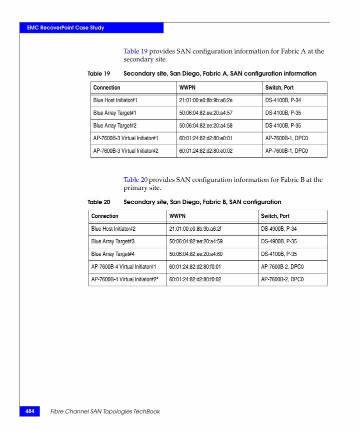
484
EMC RecoverPoint Case Study
Table 19 provides SAN configuration information for Fabric A at the secondary site.
Table 20 provides SAN configuration information for Fabric B at the primary site.
Table 19 Secondary site, San Diego, Fabric A, SAN configuration information
Connection WWPN Switch, Port
Blue Host Initiator#1 21:01:00:e0:8b:9b:a6:2e DS-4100B, P-34
Blue Array Target#1 50:06:04:82:ee:20:a4:57 DS-4100B, P-35
Blue Array Target#2 50:06:04:82:ee:20:a4:58 DS-4100B, P-35
AP-7600B-3 Virtual Initiator#1 60:01:24:82:d2:80:e0:01 AP-7600B-1, DPC0
AP-7600B-3 Virtual Initiator#2 60:01:24:82:d2:80:e0:02 AP-7600B-1, DPC0
Table 20 Secondary site, San Diego, Fabric B, SAN configuration
Connection WWPN Switch, Port
Blue Host Initiator#2 21:01:00:e0:8b:9b:a6:2f DS-4900B, P-34
Blue Array Target#3 50:06:04:82:ee:20:a4:59 DS-4900B, P-35
Blue Array Target#4 50:06:04:82:ee:20:a4:60 DS-4100B, P-35
AP-7600B-4 Virtual Initiator#1 60:01:24:82:d2:80:f0:01 AP-7600B-2, DPC0
AP-7600B-4 Virtual Initiator#2* 60:01:24:82:d2:80:f0:02 AP-7600B-2, DPC0
Fibre Channel SAN Topologies TechBook
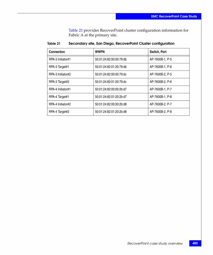
EMC RecoverPoint Case Study
Table 21 provides RecoverPoint cluster configuration information for Fabric A at the primary site.
Table 21 Secondary site, San Diego, RecoverPoint Cluster configuration
Connection WWPN Switch, Port
RPA-3 Initiator#1 50:01:24:82:00:00:79:db AP-7600B-1, P-5
RPA-3 Target#1 50:01:24:82:01:20:79:db AP-7600B-1, P-6
RPA-3 Initiator#2 50:01:24:82:00:00:79:dc AP-7600B-2, P-5
RPA-3 Target#2 50:01:24:82:01:20:79:dc AP-7600B-2, P-6
RPA-4 Initiator#1 50:01:24:82:00:00:2b:d7 AP-7600B-1, P-7
RPA-4 Target#1 50:01:24:82:01:20:2b:d7 AP-7600B-1, P-8
RPA-4 Initiator#2 50:01:24:82:00:00:2b:d8 AP-7600B-2, P-7
RPA-4 Target#2 50:01:24:82:01:20:2b:d8 AP-7600B-2, P-8
RecoverPoint case study overview 485
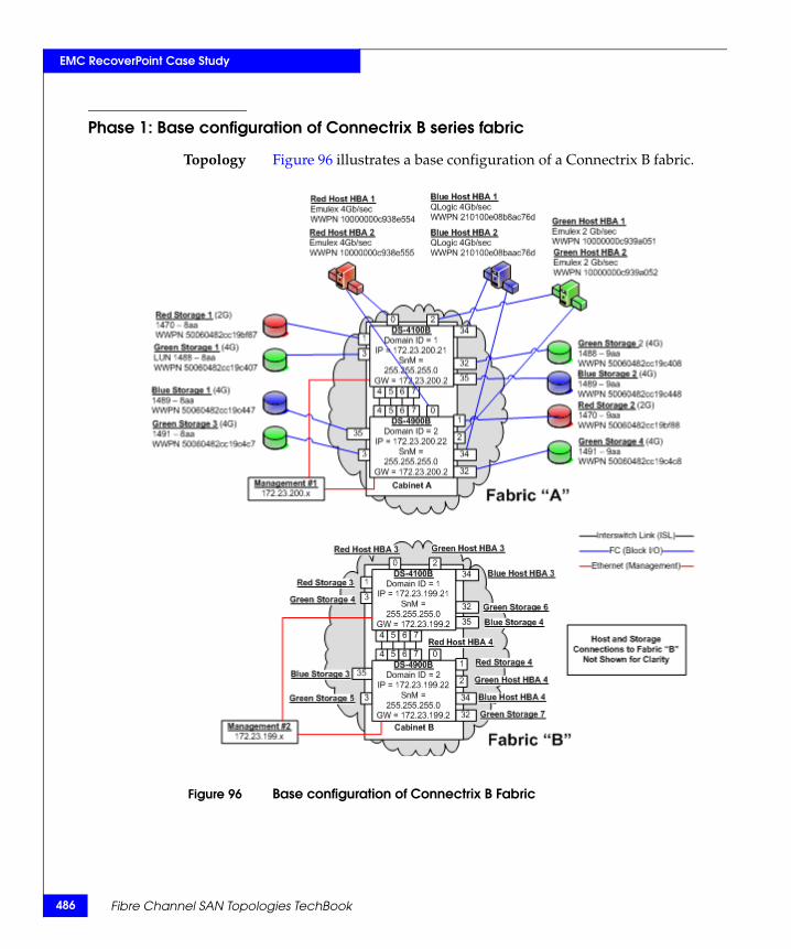
486
EMC RecoverPoint Case Study
Phase 1: Base configuration of Connectrix B series fabric
Topology Figure 96 illustrates a base configuration of a Connectrix B fabric.
Figure 96 Base configuration of Connectrix B Fabric
Fibre Channel SAN Topologies TechBook
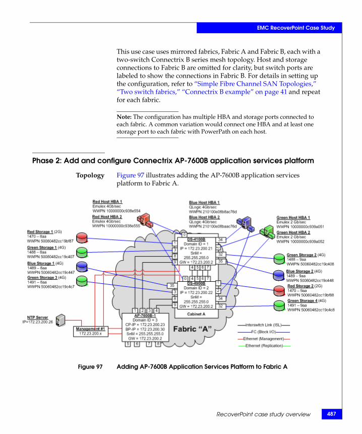
EMC RecoverPoint Case Study
This use case uses mirrored fabrics, Fabric A and Fabric B, each with a two-switch Connectrix B series mesh topology. Host and storage connections to Fabric B are omitted for clarity, but switch ports are labeled to show the connections in Fabric B. For details in setting up the configuration, refer to “Simple Fibre Channel SAN Topologies,” “Two switch fabrics,” “Connectrix B example” on page 41 and repeat for each fabric.
Note: The configuration has multiple HBA and storage ports connected to each fabric. A common variation would connect one HBA and at least one storage port to each fabric with PowerPath on each host.
Phase 2: Add and configure Connectrix AP-7600B application services platform
Topology Figure 97 illustrates adding the AP-7600B application services platform to Fabric A.
Figure 97 Adding AP-7600B Application Services Platform to Fabric A
RecoverPoint case study overview 487
488
EMC RecoverPoint Case Study
In this phase, an AP-7600B switch is added to the existing fabric. Dual ISL connections are attached to each of the existing switches to provide high availability. The two ISL connections to each switch will automatically create an ISL trunk providing a load balanced logical "pipe" with 8 Gb/s of bandwidth between the existing switches and the AP-7600B. ISL trunking provides full bandwidth utilization across multiple ISL connections and automatic redirection of traffic should an ISL be removed or fail.
As only the Blue host application is being replicated, only Blue host traffic flows through the AP-7600B. As more hosts are replicated, additional ISL connections to the AP-7600B can be added and they will automatically be included in the trunk.
Checkpoints Note: Before adding the AP-7600B application platform, it is advisable to back up critical configuration information using either Connectrix Manager, Connectrix Manager Basic, or the Brocade B series CLI.
Backup active switch configurations.Create a backup of the switch configurations in the Connectrix B fabric using the configupload command.
1. The initial communication to the AP-7600B requires a serial connection. There are two ports that need IP address information: the control processor console port (CP) and the intelligent blade processor port (BP). The CP Ethernet port is used for administrative commands (firmwaredownload, switchshow, etc.) while the BP port is used by the RecoverPoint application for controlling the write splitter service in the AP-7600B. Use the following steps to establish a serial connection and log in to the AP-7600B:
a. Verify that the AP-7600B is powered on and that POST is complete by verifying that all power LED indicators are displaying a steady green light.
Fibre Channel SAN Topologies TechBook
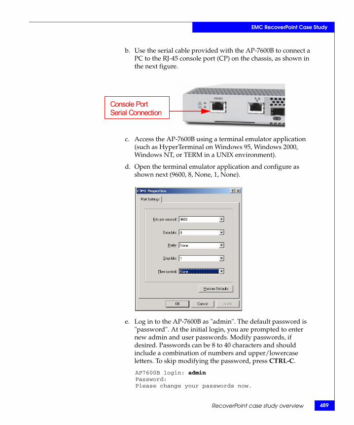
EMC RecoverPoint Case Study
b. Use the serial cable provided with the AP-7600B to connect a PC to the RJ-45 console port (CP) on the chassis, as shown in the next figure.
c. Access the AP-7600B using a terminal emulator application (such as HyperTerminal on Windows 95, Windows 2000, Windows NT, or TERM in a UNIX environment).
d. Open the terminal emulator application and configure as shown next (9600, 8, None, 1, None).
e. Log in to the AP-7600B as "admin". The default password is "password". At the initial login, you are prompted to enter new admin and user passwords. Modify passwords, if desired. Passwords can be 8 to 40 characters and should include a combination of numbers and upper/lowercase letters. To skip modifying the password, press CTRL-C.
AP7600B login: adminPassword:Please change your passwords now.
Console Port Serial Connection
RecoverPoint case study overview 489
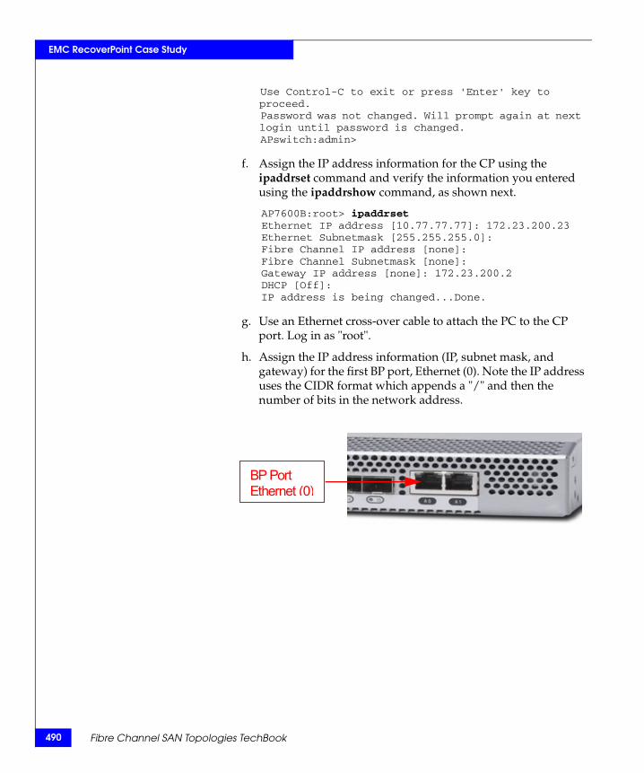
490
EMC RecoverPoint Case Study
Use Control-C to exit or press 'Enter' key to proceed.Password was not changed. Will prompt again at next login until password is changed.APswitch:admin>
f. Assign the IP address information for the CP using the ipaddrset command and verify the information you entered using the ipaddrshow command, as shown next.
AP7600B:root> ipaddrsetEthernet IP address [10.77.77.77]: 172.23.200.23Ethernet Subnetmask [255.255.255.0]:Fibre Channel IP address [none]:Fibre Channel Subnetmask [none]:Gateway IP address [none]: 172.23.200.2DHCP [Off]:IP address is being changed...Done.
g. Use an Ethernet cross-over cable to attach the PC to the CP port. Log in as "root".
h. Assign the IP address information (IP, subnet mask, and gateway) for the first BP port, Ethernet (0). Note the IP address uses the CIDR format which appends a "/" and then the number of bits in the network address.
BP Port Ethernet (0)
Fibre Channel SAN Topologies TechBook
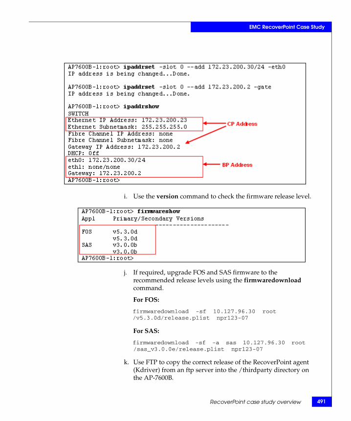
EMC RecoverPoint Case Study
i. Use the version command to check the firmware release level.
j. If required, upgrade FOS and SAS firmware to the recommended release levels using the firmwaredownload command.
For FOS:
firmwaredownload -sf 10.127.96.30 root /v5.3.0d/release.plist npr123-07
For SAS:
firmwaredownload -sf -a sas 10.127.96.30 root /sas_v3.0.0e/release.plist npr123-07
k. Use FTP to copy the correct release of the RecoverPoint agent (Kdriver) from an ftp server into the /thirdparty directory on the AP-7600B.
RecoverPoint case study overview 491
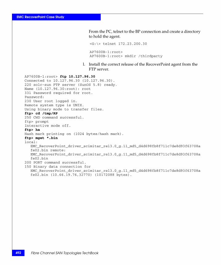
492
EMC RecoverPoint Case Study
From the PC, telnet to the BP connection and create a directory to hold the agent.
<G:\> telnet 172.23.200.30
AP7600B-1:root>AP7600B-1:root> mkdir /thirdparty
l. Install the correct release of the RecoverPoint agent from the FTP server.
AP7600B-1:root> ftp 10.127.96.30Connected to 10.127.96.30 (10.127.96.30).220 solc-sun FTP server (SunOS 5.8) ready.Name (10.127.96.30:root): root331 Password required for root.Password:230 User root logged in.Remote system type is UNIX.Using binary mode to transfer files.ftp> cd /tmp/RP250 CWD command successful.ftp> promptInteractive mode off.ftp> haHash mark printing on (1024 bytes/hash mark).ftp> mget *.binlocal:
EMC_RecoverPoint_driver_scimitar_rel3.0_g.11_md5_d4d698fb8f711c7de8d93f63708afe02.bin remote: EMC_RecoverPoint_driver_scimitar_rel3.0_g.11_md5_d4d698fb8f711c7de8d93f63708afe02.bin
200 PORT command successful.150 Binary data connection for
EMC_RecoverPoint_driver_scimitar_rel3.0_g.11_md5_d4d698fb8f711c7de8d93f63708afe02.bin (10.66.19.76,32770) (10172088 bytes).
Fibre Channel SAN Topologies TechBook
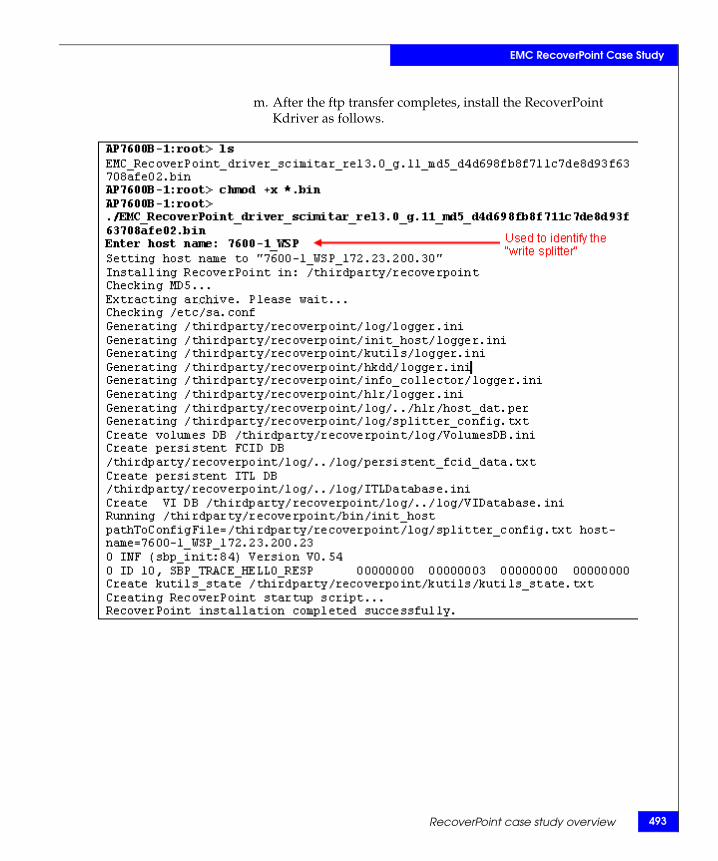
EMC RecoverPoint Case Study
m. After the ftp transfer completes, install the RecoverPoint Kdriver as follows.
RecoverPoint case study overview 493
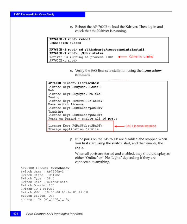
494
EMC RecoverPoint Case Study
n. Reboot the AP-7600B to load the Kdriver. Then log in and check that the Kdriver is running.
o. Verify the SAS license installation using the licenseshow command.
p. If the ports on the AP-7600B are disabled and stopped when you first start using the switch, start, and then enable, the ports.
When all ports are started and enabled, they should display as either "Online" or " No_Light," depending if they are connected to anything.
AP7600B-1:root> switchshowSwitch Name : AP7600B-1Switch State : OnlineSwitch Type : 38.0Switch Role : SubordinateSwitch Domain: 100Switch ID : FFFC64Switch WWN : 10:00:00:05:1e:01:42:b8beacon status: OFFzoning : ON (s1_3800_1_cfg)
Fibre Channel SAN Topologies TechBook
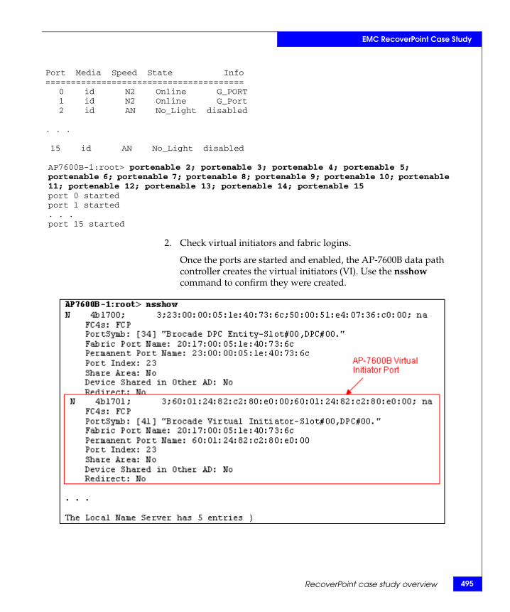
EMC RecoverPoint Case Study
Port Media Speed State Info======================================= 0 id N2 Online G_PORT 1 id N2 Online G_Port
2 id AN No_Light disabled
. . .
15 id AN No_Light disabled
AP7600B-1:root> portenable 2; portenable 3; portenable 4; portenable 5; portenable 6; portenable 7; portenable 8; portenable 9; portenable 10; portenable 11; portenable 12; portenable 13; portenable 14; portenable 15port 0 startedport 1 started. . .port 15 started
2. Check virtual initiators and fabric logins.
Once the ports are started and enabled, the AP-7600B data path controller creates the virtual initiators (VI). Use the nsshow command to confirm they were created.
RecoverPoint case study overview 495
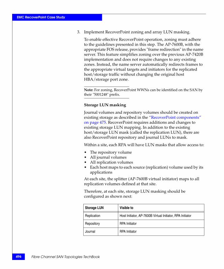
496
EMC RecoverPoint Case Study
3. Implement RecoverPoint zoning and array LUN masking.
To enable effective RecoverPoint operation, zoning must adhere to the guidelines presented in this step. The AP-7600B, with the appropriate FOS release, provides "frame redirection" in the name server. This feature simplifies zoning over the previous AP-7420B implementation and does not require changes to any existing zones. Instead, the name server automatically redirects frames to the appropriate virtual targets and initiators for the replicated host/storage traffic without changing the original host HBA/storage port zone.
Note: For zoning, RecoverPoint WWNs can be identified on the SAN by their "5001248" prefix.
Storage LUN masking
Journal volumes and repository volumes should be created on existing storage as described in the “RecoverPoint components” on page 475. RecoverPoint requires additions and changes to existing storage LUN mapping. In addition to the existing host/storage LUN mask (called the replication LUN), there are also RecoverPoint repository and journal LUNs to mask.
Within a site, each RPA will have LUN masks that allow access to:
• The repository volume• All journal volumes• All replication volumes• Each host maps to each source (replication) volume used by its
applications
At each site, the splitter (AP-7600B virtual initiator) maps to all replication volumes defined at that site.
Therefore, at each site, storage LUN masking should be configured as shown next:
Storage LUN Visible to
Replication Host Initiator, AP-7600B Virtual Initiator, RPA Initiator
Repository RPA Initiator
Journal RPA Initiator
Fibre Channel SAN Topologies TechBook
EMC RecoverPoint Case Study
Multi-path considerations
In a multi-path environment, as shown in this example, you must ensure adherence to the following guidelines:
• Each replicated host should have at least two independent paths to every RPA; that is, different host HBAs, different RPA ports, and different switches.
• Replicated hosts must have access to RPAs through all available paths.
• There should be at least two independent paths from each RPA to the storage.
• If more than one fabric is used, zoning must be the same on both fabrics.
Zoning
Three new zone types are required when adding RecoverPoint to an existing fabric. These new zones are:
• Back-end Zone — Contains AP-7600B virtual initiator and storage targets
• RPA Target Zone — Contains AP-7600B virtual initiator and RPA targets
• RPA Initiator Zone — Contains RPA initiator and storage targets
New zones are added only for hosts whose applications are being replicated by RecoverPoint. For this configuration, create these zones for the Blue host but not for the Red and Green hosts since the applications running on them are not using RecoverPoint to replicate their storage.
Each RPA port presents a target and initiator. It is best to consistently use a port as the virtual target or virtual initiator, but not both.
RecoverPoint case study overview 497
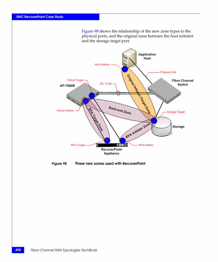
498
EMC RecoverPoint Case Study
Figure 98 shows the relationship of the new zone types to the physical ports, and the original zone between the host initiator and the storage target port.
Figure 98 Three new zones used with RecoverPoint
Fibre Channel SAN Topologies TechBook
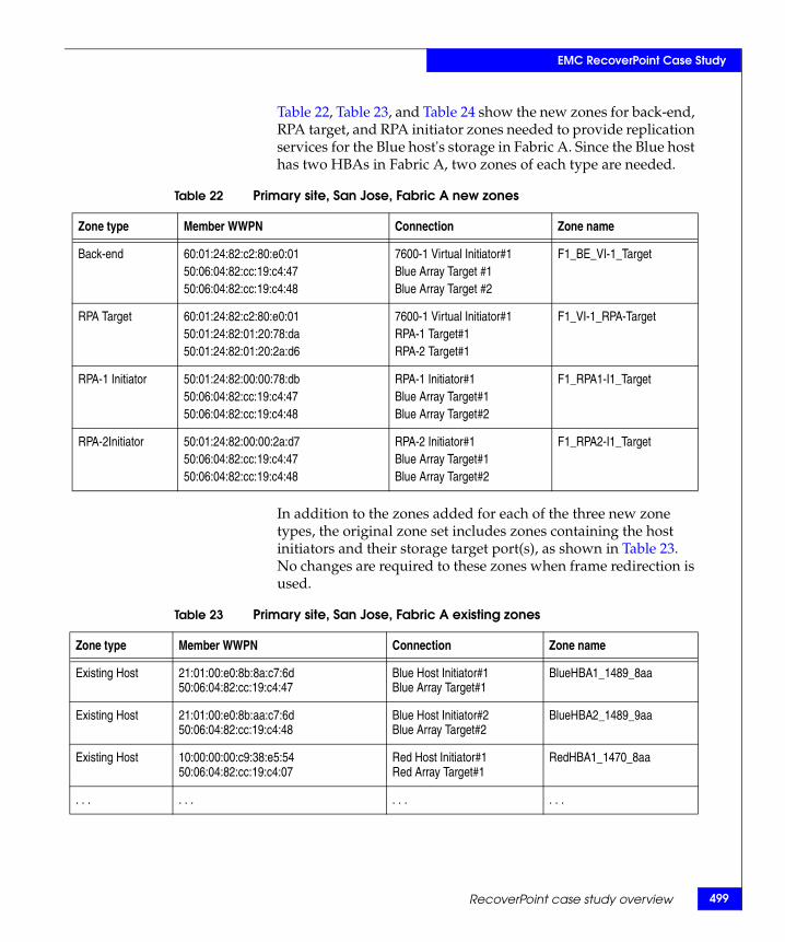
EMC RecoverPoint Case Study
Table 22, Table 23, and Table 24 show the new zones for back-end, RPA target, and RPA initiator zones needed to provide replication services for the Blue host's storage in Fabric A. Since the Blue host has two HBAs in Fabric A, two zones of each type are needed.
In addition to the zones added for each of the three new zone types, the original zone set includes zones containing the host initiators and their storage target port(s), as shown in Table 23. No changes are required to these zones when frame redirection is used.
Table 22 Primary site, San Jose, Fabric A new zones
Zone type Member WWPN Connection Zone name
Back-end 60:01:24:82:c2:80:e0:0150:06:04:82:cc:19:c4:4750:06:04:82:cc:19:c4:48
7600-1 Virtual Initiator#1Blue Array Target #1Blue Array Target #2
F1_BE_VI-1_Target
RPA Target 60:01:24:82:c2:80:e0:0150:01:24:82:01:20:78:da50:01:24:82:01:20:2a:d6
7600-1 Virtual Initiator#1RPA-1 Target#1RPA-2 Target#1
F1_VI-1_RPA-Target
RPA-1 Initiator 50:01:24:82:00:00:78:db50:06:04:82:cc:19:c4:4750:06:04:82:cc:19:c4:48
RPA-1 Initiator#1Blue Array Target#1Blue Array Target#2
F1_RPA1-I1_Target
RPA-2Initiator 50:01:24:82:00:00:2a:d750:06:04:82:cc:19:c4:4750:06:04:82:cc:19:c4:48
RPA-2 Initiator#1Blue Array Target#1 Blue Array Target#2
F1_RPA2-I1_Target
Table 23 Primary site, San Jose, Fabric A existing zones
Zone type Member WWPN Connection Zone name
Existing Host 21:01:00:e0:8b:8a:c7:6d50:06:04:82:cc:19:c4:47
Blue Host Initiator#1Blue Array Target#1
BlueHBA1_1489_8aa
Existing Host 21:01:00:e0:8b:aa:c7:6d50:06:04:82:cc:19:c4:48
Blue Host Initiator#2Blue Array Target#2
BlueHBA2_1489_9aa
Existing Host 10:00:00:00:c9:38:e5:5450:06:04:82:cc:19:c4:07
Red Host Initiator#1Red Array Target#1
RedHBA1_1470_8aa
. . . . . . . . . . . .
RecoverPoint case study overview 499
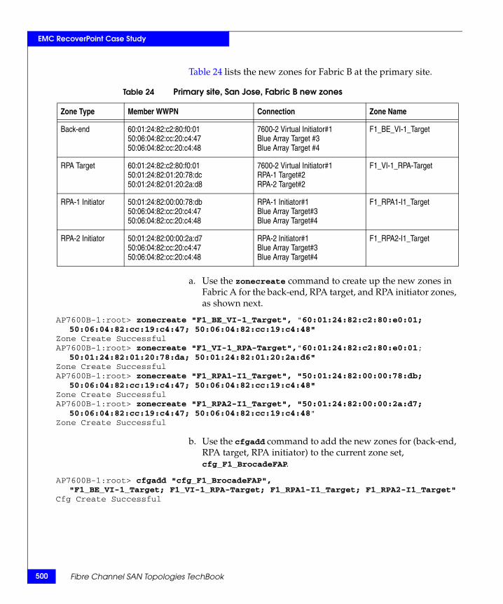
500
EMC RecoverPoint Case Study
Table 24 lists the new zones for Fabric B at the primary site.
a. Use the zonecreate command to create up the new zones in Fabric A for the back-end, RPA target, and RPA initiator zones, as shown next.
AP7600B-1:root> zonecreate "F1_BE_VI-1_Target", "60:01:24:82:c2:80:e0:01; 50:06:04:82:cc:19:c4:47; 50:06:04:82:cc:19:c4:48"
Zone Create SuccessfulAP7600B-1:root> zonecreate "F1_VI-1_RPA-Target","60:01:24:82:c2:80:e0:01;
50:01:24:82:01:20:78:da; 50:01:24:82:01:20:2a:d6"Zone Create SuccessfulAP7600B-1:root> zonecreate "F1_RPA1-I1_Target", "50:01:24:82:00:00:78:db;
50:06:04:82:cc:19:c4:47; 50:06:04:82:cc:19:c4:48"Zone Create SuccessfulAP7600B-1:root> zonecreate "F1_RPA2-I1_Target", "50:01:24:82:00:00:2a:d7;
50:06:04:82:cc:19:c4:47; 50:06:04:82:cc:19:c4:48"Zone Create Successful
b. Use the cfgadd command to add the new zones for (back-end, RPA target, RPA initiator) to the current zone set, cfg_F1_BrocadeFAP.
AP7600B-1:root> cfgadd "cfg_F1_BrocadeFAP", "F1_BE_VI-1_Target; F1_VI-1_RPA-Target; F1_RPA1-I1_Target; F1_RPA2-I1_Target"
Cfg Create Successful
Table 24 Primary site, San Jose, Fabric B new zones
Zone Type Member WWPN Connection Zone Name
Back-end 60:01:24:82:c2:80:f0:0150:06:04:82:cc:20:c4:4750:06:04:82:cc:20:c4:48
7600-2 Virtual Initiator#1Blue Array Target #3Blue Array Target #4
F1_BE_VI-1_Target
RPA Target 60:01:24:82:c2:80:f0:0150:01:24:82:01:20:78:dc50:01:24:82:01:20:2a:d8
7600-2 Virtual Initiator#1RPA-1 Target#2RPA-2 Target#2
F1_VI-1_RPA-Target
RPA-1 Initiator 50:01:24:82:00:00:78:db50:06:04:82:cc:20:c4:4750:06:04:82:cc:20:c4:48
RPA-1 Initiator#1Blue Array Target#3Blue Array Target#4
F1_RPA1-I1_Target
RPA-2 Initiator 50:01:24:82:00:00:2a:d750:06:04:82:cc:20:c4:4750:06:04:82:cc:20:c4:48
RPA-2 Initiator#1Blue Array Target#3 Blue Array Target#4
F1_RPA2-I1_Target
Fibre Channel SAN Topologies TechBook
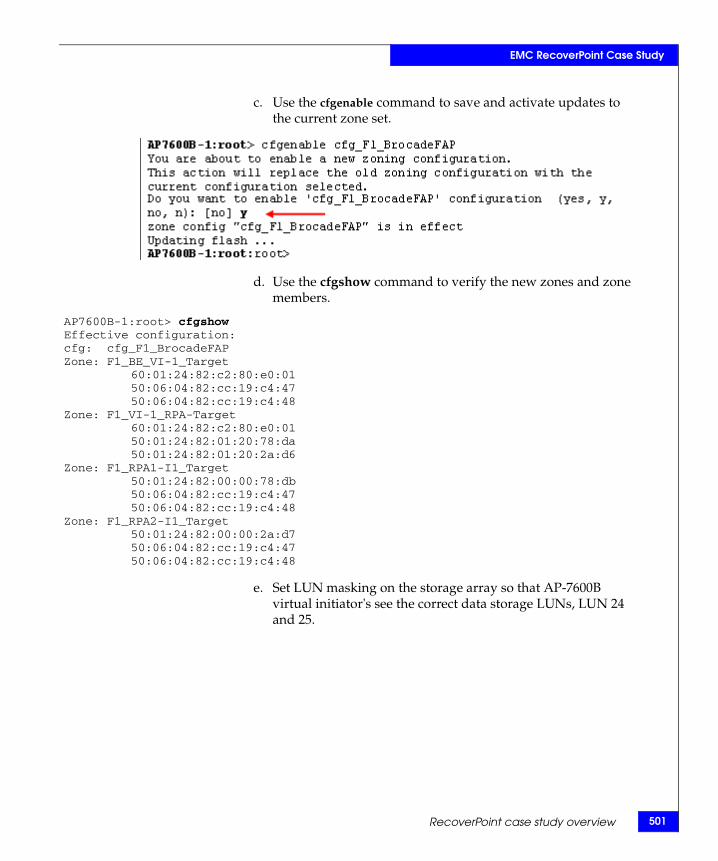
EMC RecoverPoint Case Study
c. Use the cfgenable command to save and activate updates to the current zone set.
d. Use the cfgshow command to verify the new zones and zone members.
AP7600B-1:root> cfgshowEffective configuration:cfg: cfg_F1_BrocadeFAPZone: F1_BE_VI-1_Target
60:01:24:82:c2:80:e0:0150:06:04:82:cc:19:c4:4750:06:04:82:cc:19:c4:48
Zone: F1_VI-1_RPA-Target60:01:24:82:c2:80:e0:0150:01:24:82:01:20:78:da50:01:24:82:01:20:2a:d6
Zone: F1_RPA1-I1_Target50:01:24:82:00:00:78:db50:06:04:82:cc:19:c4:4750:06:04:82:cc:19:c4:48
Zone: F1_RPA2-I1_Target50:01:24:82:00:00:2a:d750:06:04:82:cc:19:c4:4750:06:04:82:cc:19:c4:48
e. Set LUN masking on the storage array so that AP-7600B virtual initiator's see the correct data storage LUNs, LUN 24 and 25.
RecoverPoint case study overview 501
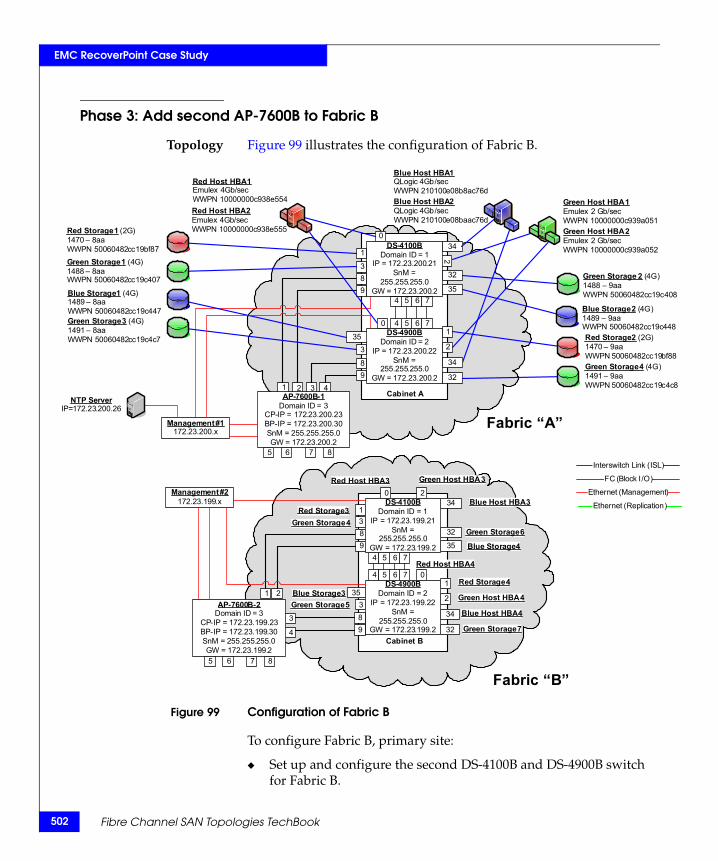
502
EMC RecoverPoint Case Study
R1WG1W
B1WG1W
88
08
48
c8
IP
Phase 3: Add second AP-7600B to Fabric B
Topology Figure 99 illustrates the configuration of Fabric B.
Figure 99 Configuration of Fabric B
To configure Fabric B, primary site:
◆ Set up and configure the second DS-4100B and DS-4900B switch for Fabric B.
Fabric “B”
Management #2172.23.199.x
Cabinet A
034
2
4
32
1
32
35
1
3
3
P
4
2
5
5
6
6
7
7
8
8
9
9
Fabric “A”
AP-7600B-2Domain ID = 3
CP-IP = 172.23.199.23BP-IP = 172.23.199.30SnM = 255.255.255.0GW = 172.23.199.2
3
4
1 2
5 6 7 8
3 41 2
5 6 7 8
FC (Block I/O)
Ethernet (Management)
Interswitch Link (ISL)
Ethernet (Replication)
ed Storage 1 (2G)470 – 8aaWPN 50060482cc19bf87reen Storage 1 (4G)488 – 8aaWPN 50060482cc19c407
lue Storage 1 (4G)489 – 8aaWPN 50060482cc19c447reen Storage 3 (4G)491 – 8aaWPN 50060482cc19c4c7 Red Storage 2 (2G)
1470 – 9aaWWPN 50060482cc19bf
Green Storage 2 (4G)1488 – 9aaWWPN 50060482cc19c4
Blue Storage 2 (4G)1489 – 9aaWWPN 50060482cc19c4
Green Storage 4 (4G)1491 – 9aaWWPN 50060482cc19c4
Red Host HBA 1Emulex 4Gb/secWWPN 10000000c938e554Red Host HBA 2Emulex 4Gb/secWWPN 10000000c938e555
Green Host HBA 1Emulex 2 Gb/secWWPN 10000000c939a051Green Host HBA 2Emulex 2 Gb/secWWPN 10000000c939a052
Blue Host HBA 1QLogic 4Gb/secWWPN 210100e08b8ac76dBlue Host HBA 2QLogic 4Gb/secWWPN 210100e08baac76d
35
34
AP-7600B-1Domain ID = 3
CP-IP = 172.23.200.23BP-IP = 172.23.200.30SnM = 255.255.255.0GW = 172.23.200.2
DS-4900BDomain ID = 2
IP = 172.23.200.22SnM =
255.255.255.0GW = 172.23.200.2
DS-4100BDomain ID = 1
IP = 172.23.200.21SnM =
255.255.255.0GW = 172.23.200.2
0
Management #1172.23.200.x
NTP Server=172.23.200.26
Cabinet B
034
2
4 0
34
32
1
32
35
13
353
P
4
2
5
5
6
6
7
7
DS-4100BDomain ID = 1
IP = 172.23.199.21SnM =
255.255.255.0GW = 172.23.199.2
DS-4900BDomain ID = 2
IP = 172.23.199.22SnM =
255.255.255.0GW = 172.23.199.2
Red Host HBA 3
Red Host HBA 4
Green Host HBA 3
Green Host HBA 4
Blue Host HBA 3
Blue Host HBA 4
Red Storage 3
Red Storage 4
Green Storage 4
Green Storage 5
Green Storage 7
Blue Storage 3
Blue Storage 4
Green Storage 689
89
Fabric “B”
Fibre Channel SAN Topologies TechBook
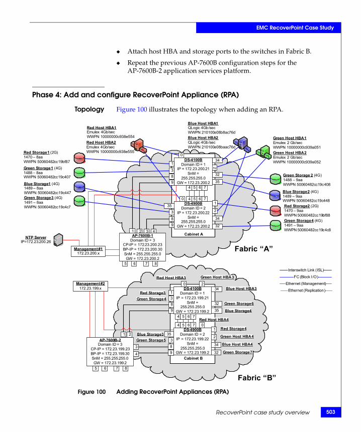
EMC RecoverPoint Case Study
R14WG14W
B1WG1W
8
8
8
8
NIP=
◆ Attach host HBA and storage ports to the switches in Fabric B.
◆ Repeat the previous AP-7600B configuration steps for the AP-7600B-2 application services platform.
Phase 4: Add and configure RecoverPoint Appliance (RPA)
Topology Figure 100 illustrates the topology when adding an RPA.
Figure 100 Adding RecoverPoint Appliances (RPA)
Fabric “B”
Management #2172.23.199.x
Cabinet A
034
2
4
32
1
32
35
1
3
3
P
4
2
5
5
6
6
7
7
8
8
9
9
Fabric “A”
AP-7600B-2Domain ID = 3
CP-IP = 172.23.199.23BP-IP = 172.23.199.30SnM = 255.255.255.0GW = 172.23.199.2
3
4
1 2
5 6 7 8
3 41 2
5 6 7 8
FC (Block I/O)
Ethernet (Management)
Interswitch Link (ISL)
Ethernet (Replication)
ed Storage 1 (2G)70 – 8aaWPN 50060482cc19bf87reen Storage 1 (4G)88 – 8aaWPN 50060482cc19c407
lue Storage 1 (4G)489 – 8aaWPN 50060482cc19c447reen Storage 3 (4G)491 – 8aaWPN 50060482cc19c4c7 Red Storage 2 (2G)
1470 – 9aaWWPN 50060482cc19bf8
Green Storage 2 (4G)1488 – 9aaWWPN 50060482cc19c40
Blue Storage 2 (4G)1489 – 9aaWWPN 50060482cc19c44
Green Storage 4 (4G)1491 – 9aaWWPN 50060482cc19c4c
Red Host HBA 1Emulex 4Gb/secWWPN 10000000c938e554Red Host HBA 2Emulex 4Gb/secWWPN 10000000c938e555
Green Host HBA 1Emulex 2 Gb/secWWPN 10000000c939a051Green Host HBA 2Emulex 2 Gb/secWWPN 10000000c939a052
Blue Host HBA 1QLogic 4Gb/secWWPN 210100e08b8ac76dBlue Host HBA 2QLogic 4Gb/secWWPN 210100e08baac76d
35
34
AP-7600B-1Domain ID = 3
CP-IP = 172.23.200.23BP-IP = 172.23.200.30SnM = 255.255.255.0GW = 172.23.200.2
DS-4900BDomain ID = 2
IP = 172.23.200.22SnM =
255.255.255.0GW = 172.23.200.2
DS-4100BDomain ID = 1
IP = 172.23.200.21SnM =
255.255.255.0GW = 172.23.200.2
0
Management #1172.23.200.x
TP Server172.23.200.26
Cabinet B
034
2
4 0
34
32
1
32
35
13
353
P
4
2
5
5
6
6
7
7
DS-4100BDomain ID = 1
IP = 172.23.199.21SnM =
255.255.255.0GW = 172.23.199.2
DS-4900BDomain ID = 2
IP = 172.23.199.22SnM =
255.255.255.0GW = 172.23.199.2
Red Host HBA 3
Red Host HBA 4
Green Host HBA 3
Green Host HBA 4
Blue Host HBA 3
Blue Host HBA 4
Red Storage 3
Red Storage 4
Green Storage 4
Green Storage 5
Green Storage 7
Blue Storage 3
Blue Storage 4
Green Storage 689
89
Fabric “B”
RecoverPoint case study overview 503
504
EMC RecoverPoint Case Study
Checkpoints ◆ Before you install the RPA in San Jose, ensure that sufficient volumes are available on the SAN-attached storage for use by RecoverPoint for repository and journal volumes. If you need to create journal and repository volumes, “RecoverPoint storage components” on page 475 describes these volumes and how to size them.
◆ You should LUN mask the journal and repository volumes to make them visible to the RPA. Do not LUN mask the recovery volume (data volume) for the RPA at this time (to avoid possible data destruction).
◆ Use the cfgshow command to make sure zoning is correctly configured as described in the following step: “Implement RecoverPoint zoning and array LUN masking.” on page 496.
1. Install the RecoverPoint Appliance (RPA).
a. The first site to install is the site with the NTP server, which in this example is the San Jose site.
b. Unpack the RPA. Each RPA package should contain the following:
– One RecoverPoint appliance– One RecoverPoint appliance rack mount kit– One country-specific power cable
2. Physically install the RPA hardware.
The RPAs should be installed independently at the primary and secondary sites. To install each of the RPAs at a site, you must first:
a. Install the new RPAs in the rack at the first site.
b. Ensure that all of the RPAs are powered off (power switch in "OFF" position) before connecting the power cables.
c. Connect a Fibre Channel cable from the ports on the host bus adapters (HBA) on the RPA to the specified ports on the AP-7600B switch.
d. Connect Ethernet cables from the RPA to the management and WAN IP networks.
3. Set up the primary site (San Jose, RPA-1 setup).
Fibre Channel SAN Topologies TechBook
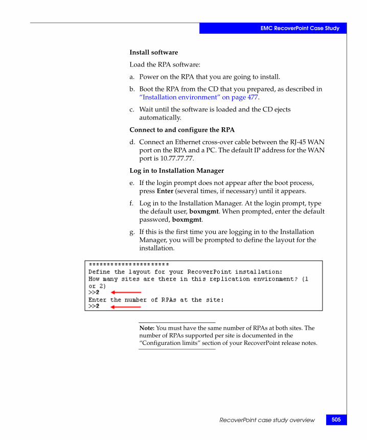
EMC RecoverPoint Case Study
Install software
Load the RPA software:
a. Power on the RPA that you are going to install.
b. Boot the RPA from the CD that you prepared, as described in “Installation environment” on page 477.
c. Wait until the software is loaded and the CD ejects automatically.
Connect to and configure the RPA
d. Connect an Ethernet cross-over cable between the RJ-45 WAN port on the RPA and a PC. The default IP address for the WAN port is 10.77.77.77.
Log in to Installation Manager
e. If the login prompt does not appear after the boot process, press Enter (several times, if necessary) until it appears.
f. Log in to the Installation Manager. At the login prompt, type the default user, boxmgmt. When prompted, enter the default password, boxmgmt.
g. If this is the first time you are logging in to the Installation Manager, you will be prompted to define the layout for the installation.
Note: You must have the same number of RPAs at both sites. The number of RPAs supported per site is documented in the “Configuration limits” section of your RecoverPoint release notes.
RecoverPoint case study overview 505
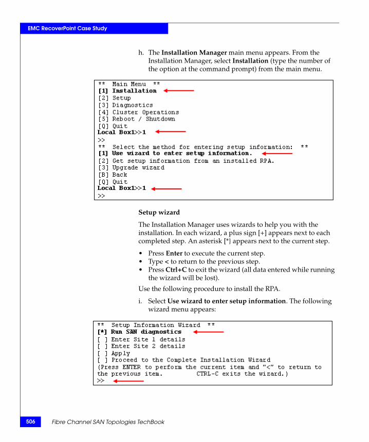
506
EMC RecoverPoint Case Study
h. The Installation Manager main menu appears. From the Installation Manager, select Installation (type the number of the option at the command prompt) from the main menu.
Setup wizard
The Installation Manager uses wizards to help you with the installation. In each wizard, a plus sign [+] appears next to each completed step. An asterisk [*} appears next to the current step.
• Press Enter to execute the current step.• Type < to return to the previous step.• Press Ctrl+C to exit the wizard (all data entered while running
the wizard will be lost).
Use the following procedure to install the RPA.
i. Select Use wizard to enter setup information. The following wizard menu appears:
Fibre Channel SAN Topologies TechBook
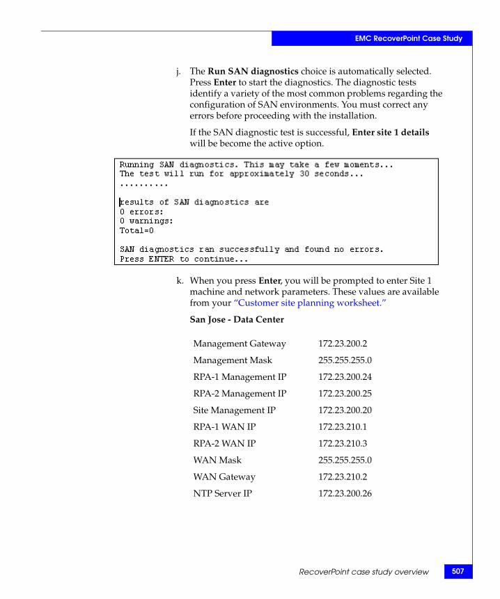
EMC RecoverPoint Case Study
j. The Run SAN diagnostics choice is automatically selected. Press Enter to start the diagnostics. The diagnostic tests identify a variety of the most common problems regarding the configuration of SAN environments. You must correct any errors before proceeding with the installation.
If the SAN diagnostic test is successful, Enter site 1 details will be become the active option.
k. When you press Enter, you will be prompted to enter Site 1 machine and network parameters. These values are available from your “Customer site planning worksheet.”
San Jose - Data Center
Management Gateway 172.23.200.2
Management Mask 255.255.255.0
RPA-1 Management IP 172.23.200.24
RPA-2 Management IP 172.23.200.25
Site Management IP 172.23.200.20
RPA-1 WAN IP 172.23.210.1
RPA-2 WAN IP 172.23.210.3
WAN Mask 255.255.255.0
WAN Gateway 172.23.210.2
NTP Server IP 172.23.200.26
RecoverPoint case study overview 507
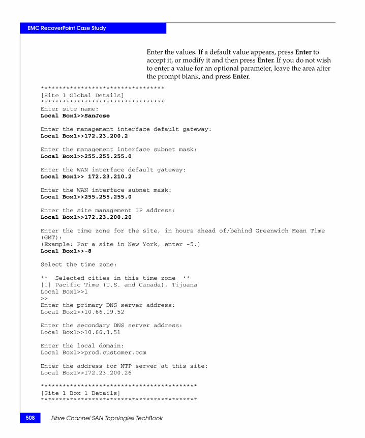
508
EMC RecoverPoint Case Study
Enter the values. If a default value appears, press Enter to accept it, or modify it and then press Enter. If you do not wish to enter a value for an optional parameter, leave the area after the prompt blank, and press Enter.
**********************************[Site 1 Global Details]**********************************Enter site name:Local Box1>>SanJose
Enter the management interface default gateway:Local Box1>>172.23.200.2
Enter the management interface subnet mask:Local Box1>>255.255.255.0
Enter the WAN interface default gateway:Local Box1>> 172.23.210.2
Enter the WAN interface subnet mask:Local Box1>>255.255.255.0
Enter the site management IP address:Local Box1>>172.23.200.20
Enter the time zone for the site, in hours ahead of/behind Greenwich Mean Time (GMT):(Example: For a site in New York, enter -5.)Local Box1>>-8
Select the time zone:
** Selected cities in this time zone **[1] Pacific Time (U.S. and Canada), TijuanaLocal Box1>>1>>Enter the primary DNS server address:Local Box1>>10.66.19.52
Enter the secondary DNS server address:Local Box1>>10.66.3.51
Enter the local domain:Local Box1>>prod.customer.com
Enter the address for NTP server at this site:Local Box1>>172.23.200.26
*******************************************[Site 1 Box 1 Details]*******************************************
Fibre Channel SAN Topologies TechBook
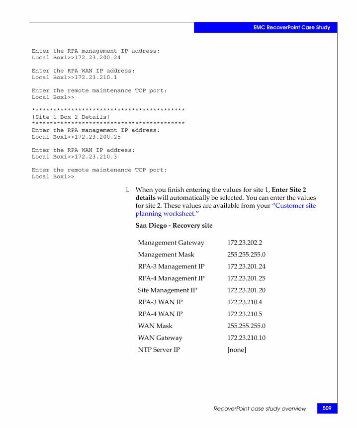
EMC RecoverPoint Case Study
Enter the RPA management IP address:Local Box1>>172.23.200.24
Enter the RPA WAN IP address:Local Box1>>172.23.210.1
Enter the remote maintenance TCP port:Local Box1>>
*******************************************[Site 1 Box 2 Details]*******************************************Enter the RPA management IP address:Local Box1>>172.23.200.25
Enter the RPA WAN IP address:Local Box1>>172.23.210.3
Enter the remote maintenance TCP port:Local Box1>>
l. When you finish entering the values for site 1, Enter Site 2 details will automatically be selected. You can enter the values for site 2. These values are available from your “Customer site planning worksheet.”
San Diego - Recovery site
Management Gateway 172.23.202.2
Management Mask 255.255.255.0
RPA-3 Management IP 172.23.201.24
RPA-4 Management IP 172.23.201.25
Site Management IP 172.23.201.20
RPA-3 WAN IP 172.23.210.4
RPA-4 WAN IP 172.23.210.5
WAN Mask 255.255.255.0
WAN Gateway 172.23.210.10
NTP Server IP [none]
RecoverPoint case study overview 509
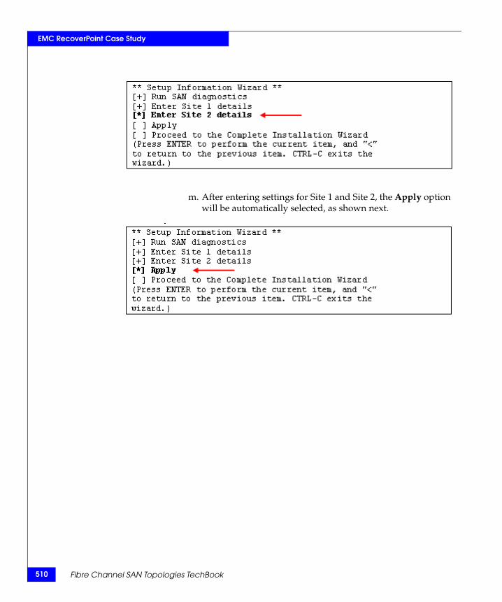
510
EMC RecoverPoint Case Study
m. After entering settings for Site 1 and Site 2, the Apply option will be automatically selected, as shown next.
Fibre Channel SAN Topologies TechBook
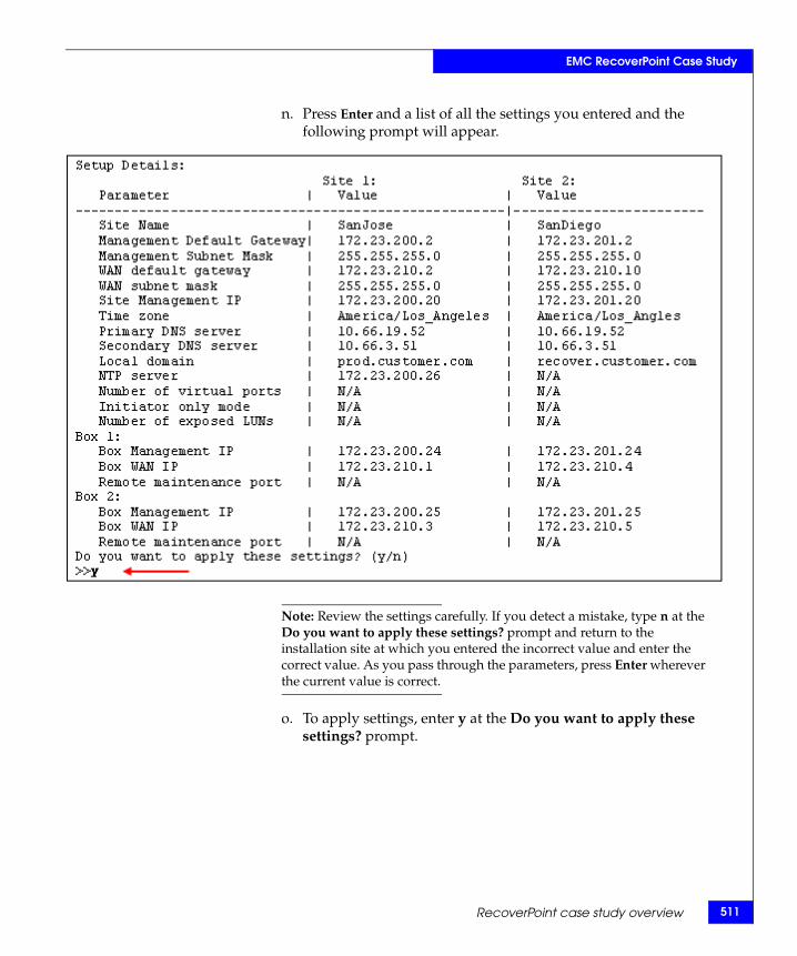
EMC RecoverPoint Case Study
n. Press Enter and a list of all the settings you entered and the following prompt will appear.
Note: Review the settings carefully. If you detect a mistake, type n at the Do you want to apply these settings? prompt and return to the installation site at which you entered the incorrect value and enter the correct value. As you pass through the parameters, press Enter wherever the current value is correct.
o. To apply settings, enter y at the Do you want to apply these settings? prompt.
RecoverPoint case study overview 511
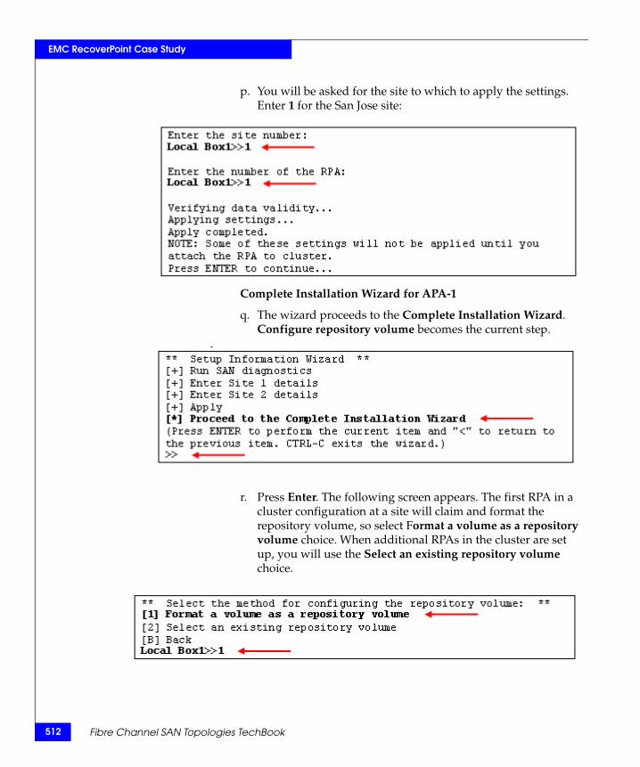
512
EMC RecoverPoint Case Study
p. You will be asked for the site to which to apply the settings. Enter 1 for the San Jose site:
Complete Installation Wizard for APA-1
q. The wizard proceeds to the Complete Installation Wizard. Configure repository volume becomes the current step.
r. Press Enter. The following screen appears. The first RPA in a cluster configuration at a site will claim and format the repository volume, so select Format a volume as a repository volume choice. When additional RPAs in the cluster are set up, you will use the Select an existing repository volume choice.
Fibre Channel SAN Topologies TechBook
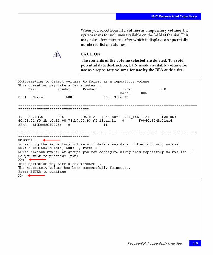
EMC RecoverPoint Case Study
When you select Format a volume as a repository volume, the system scans for volumes available on the SAN at the site. This may take a few minutes, after which it displays a sequentially numbered list of volumes.
CAUTION!The contents of the volume selected are deleted. To avoid potential data destruction, LUN mask a suitable volume for use as a repository volume for use by the RPA at this site.
RecoverPoint case study overview 513
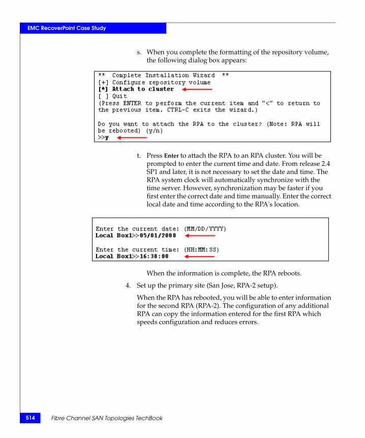
514
EMC RecoverPoint Case Study
s. When you complete the formatting of the repository volume, the following dialog box appears:
t. Press Enter to attach the RPA to an RPA cluster. You will be prompted to enter the current time and date. From release 2.4 SP1 and later, it is not necessary to set the date and time. The RPA system clock will automatically synchronize with the time server. However, synchronization may be faster if you first enter the correct date and time manually. Enter the correct local date and time according to the RPA's location.
When the information is complete, the RPA reboots.
4. Set up the primary site (San Jose, RPA-2 setup).
When the RPA has rebooted, you will be able to enter information for the second RPA (RPA-2). The configuration of any additional RPA can copy the information entered for the first RPA which speeds configuration and reduces errors.
Fibre Channel SAN Topologies TechBook
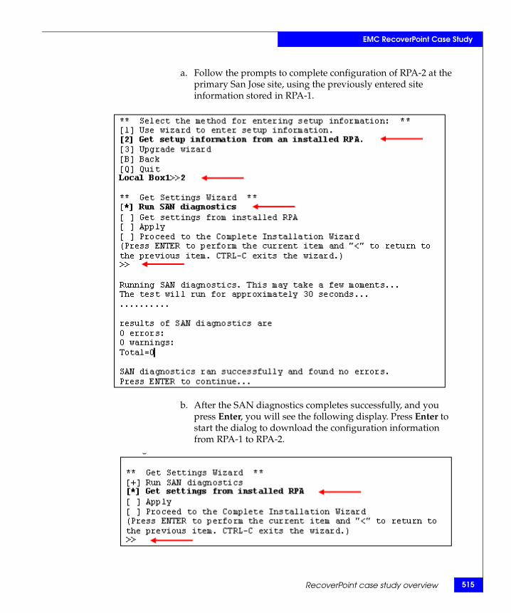
EMC RecoverPoint Case Study
a. Follow the prompts to complete configuration of RPA-2 at the primary San Jose site, using the previously entered site information stored in RPA-1.
b. After the SAN diagnostics completes successfully, and you press Enter, you will see the following display. Press Enter to start the dialog to download the configuration information from RPA-1 to RPA-2.
RecoverPoint case study overview 515
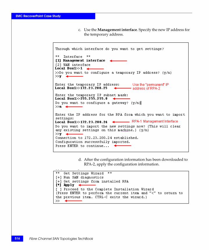
516
EMC RecoverPoint Case Study
c. Use the Management interface. Specify the new IP address for the temporary address.
d. After the configuration information has been downloaded to RPA-2, apply the configuration information.
Fibre Channel SAN Topologies TechBook
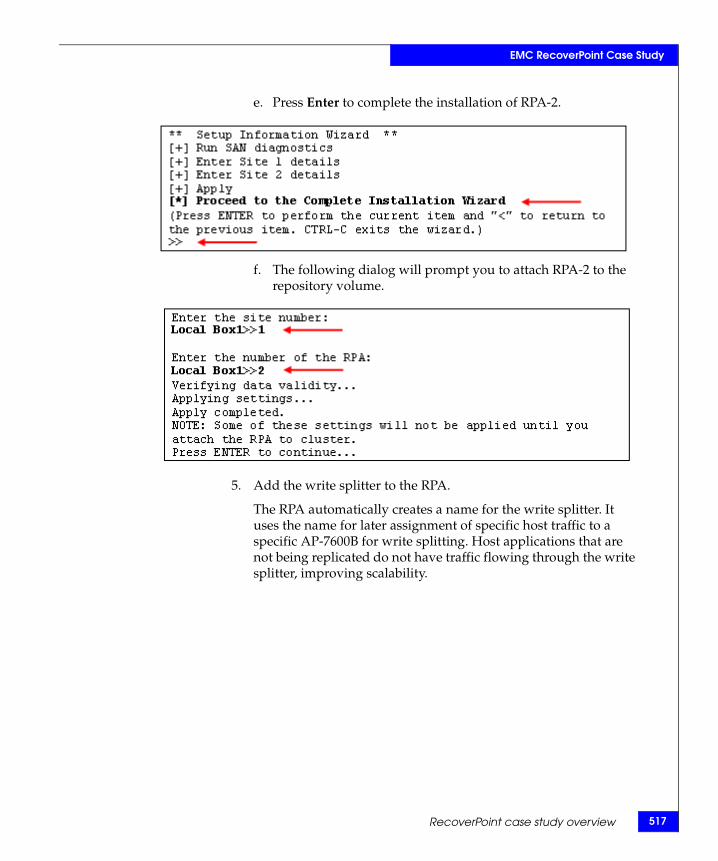
EMC RecoverPoint Case Study
e. Press Enter to complete the installation of RPA-2.
f. The following dialog will prompt you to attach RPA-2 to the repository volume.
5. Add the write splitter to the RPA.
The RPA automatically creates a name for the write splitter. It uses the name for later assignment of specific host traffic to a specific AP-7600B for write splitting. Host applications that are not being replicated do not have traffic flowing through the write splitter, improving scalability.
RecoverPoint case study overview 517
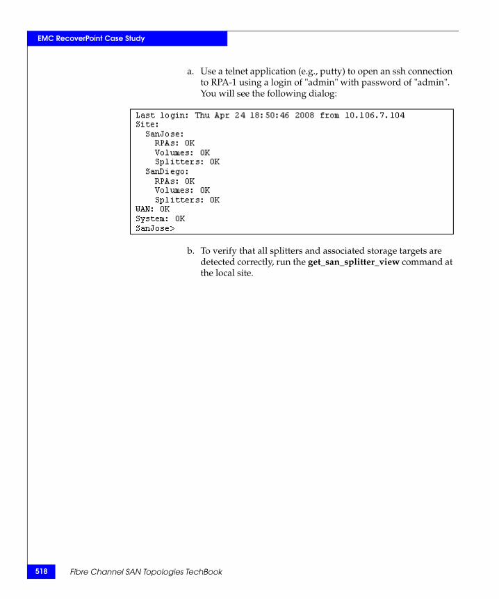
518
EMC RecoverPoint Case Study
a. Use a telnet application (e.g., putty) to open an ssh connection to RPA-1 using a login of "admin" with password of "admin". You will see the following dialog:
b. To verify that all splitters and associated storage targets are detected correctly, run the get_san_splitter_view command at the local site.
Fibre Channel SAN Topologies TechBook
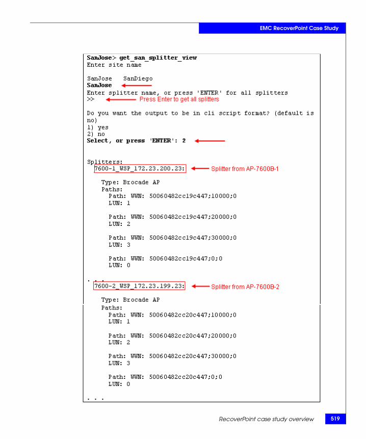
EMC RecoverPoint Case Study
RecoverPoint case study overview 519
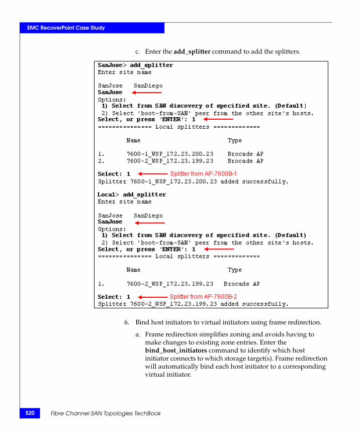
520
EMC RecoverPoint Case Study
c. Enter the add_splitter command to add the splitters.
6. Bind host initiators to virtual initiators using frame redirection.
a. Frame redirection simplifies zoning and avoids having to make changes to existing zone entries. Enter the bind_host_initiators command to identify which host initiator connects to which storage target(s). Frame redirection will automatically bind each host initiator to a corresponding virtual initiator.
Fibre Channel SAN Topologies TechBook
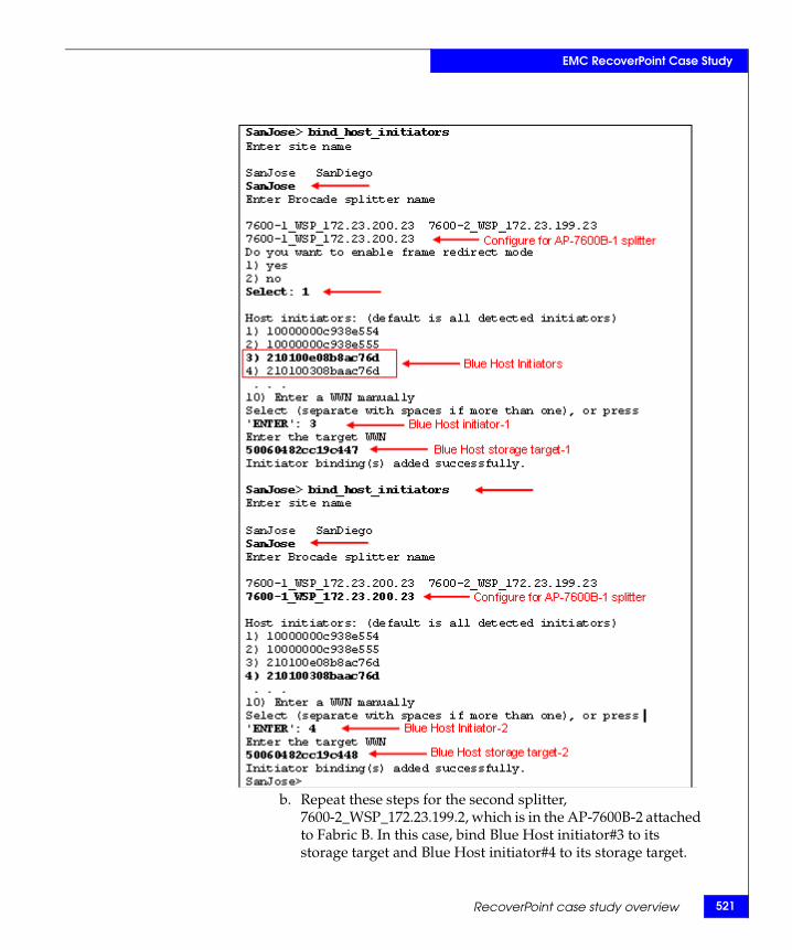
EMC RecoverPoint Case Study
b. Repeat these steps for the second splitter, 7600-2_WSP_172.23.199.2, which is in the AP-7600B-2 attached to Fabric B. In this case, bind Blue Host initiator#3 to its storage target and Blue Host initiator#4 to its storage target.
RecoverPoint case study overview 521
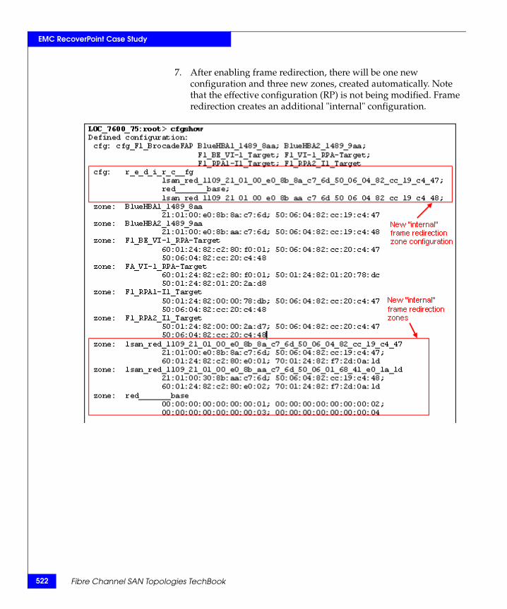
522
EMC RecoverPoint Case Study
7. After enabling frame redirection, there will be one new configuration and three new zones, created automatically. Note that the effective configuration (RP) is not being modified. Frame redirection creates an additional "internal" configuration.
Fibre Channel SAN Topologies TechBook
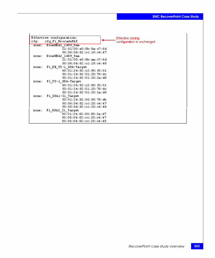
EMC RecoverPoint Case Study
RecoverPoint case study overview 523
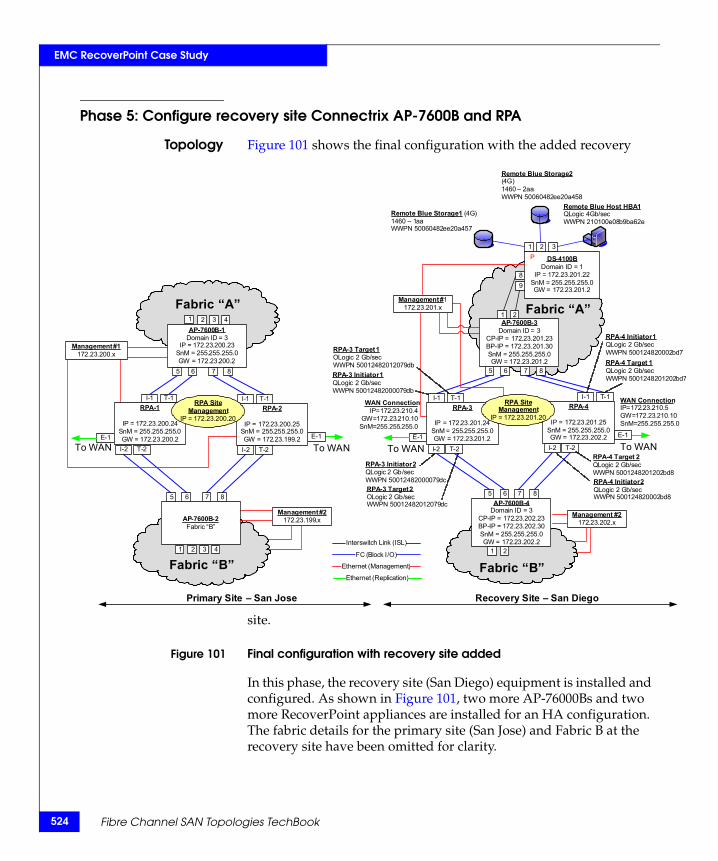
524
EMC RecoverPoint Case Study
2bd7
02bd7
on
.1055.0
8
d8
Phase 5: Configure recovery site Connectrix AP-7600B and RPA
Topology Figure 101 shows the final configuration with the added recovery
site.
Figure 101 Final configuration with recovery site added
In this phase, the recovery site (San Diego) equipment is installed and configured. As shown in Figure 101, two more AP-76000Bs and two more RecoverPoint appliances are installed for an HA configuration. The fabric details for the primary site (San Jose) and Fabric B at the recovery site have been omitted for clarity.
Fabric “B”Fabric “B”
Fabric “A”
DS-4100BDomain ID = 1
IP = 172.23.201.22SnM = 255.255.255.0GW = 172.23.201.2
89
1 2
Management #1172.23.201.x
Primary Site – San Jose Recovery Site – San Diego
3
Remote Blue Host HBA 1QLogic 4Gb/secWWPN 210100e08b9ba62e
Remote Blue Storage 2(4G)1460 – 2aaWWPN 50060482ee20a458
Remote Blue Storage 1 (4G)1460 – 1aaWWPN 50060482ee20a457
RPA-3 Initiator 1QLogic 2 Gb/secWWPN 50012482000079db
RPA-4 Initiator 1QLogic 2 Gb/secWWPN 50012482000
P
RPA-3 Target 1OLogic 2 Gb/secWWPN 50012482012079db RPA-4 Target 1
QLogic 2 Gb/secWWPN 50012482012
Fabric “A”
Management #2172.23.202.x
WAN ConnectiIP=172.23.210.5GW=172.23.210SnM=255.255.2
I-1 T-1
I-2 T-2
E-1
I-1 T-1
I-2 T-2
1 2
5 6 7 8
1 2
5 6 7 8
FC (Block I/O)
Ethernet (Management)
Interswitch Link (ISL)
Ethernet (Replication)
WAN ConnectionIP=172.23.210.4
GW=172.23.210.10SnM=255.255.255.0
E-1
RPA-3
IP = 172.23.201.24SnM = 255.255.255.0GW = 172.23.201.2
AP-7600B-3Domain ID = 3
CP-IP = 172.23.201.23BP-IP = 172.23.201.30SnM = 255.255.255.0GW = 172.23.201.2
To WAN To WANTo WAN
Management #2172.23.199.x
I-1 T-1
I-2 T-2
E-1
I-1 T-1
I-2 T-2
AP-7600B-2Fabric “B”
3 41 2
5 6 7 8
3 41 2
5 6 7 8
To WANE-1
RPA-2
IP = 172.23.200.25SnM = 255.255.255.0GW = 172.23.199.2
RPA-1
IP = 172.23.200.24SnM = 255.255.255.0GW = 172.23.200.2
AP-7600B-1Domain ID = 3
IP = 172.23.200.23SnM = 255.255.255.0GW = 172.23.200.2
Management #1172.23.200.x
RPA Site Management
IP = 172.23.200.20
AP-7600B-4Domain ID = 3
CP-IP = 172.23.202.23BP-IP = 172.23.202.30SnM = 255.255.255.0GW = 172.23.202.2
RPA-4
IP = 172.23.201.25SnM = 255.255.255.0GW = 172.23.202.2
RPA Site Management
IP = 172.23.201.20
RPA-4 Initiator 2QLogic 2 Gb/secWWPN 500124820002bd
RPA-4 Target 2QLogic 2 Gb/secWWPN 5001248201202b
RPA-3 Initiator 2QLogic 2 Gb/secWWPN 50012482000079dcRPA-3 Target 2OLogic 2 Gb/secWWPN 50012482012079dc
Fibre Channel SAN Topologies TechBook
EMC RecoverPoint Case Study
Checkpoints ◆ Before you install the RPA, ensure that sufficient volumes are available in San Diego on the SAN-attached storage for use by RecoverPoint for the repository, journal, and replication volumes. If you need to create journal, and repository volumes, “RecoverPoint storage components” on page 475 describes these volumes and how to size them.
◆ Make sure zoning is correctly configured as described in the following step: “Implement RecoverPoint zoning and array LUN masking.” on page 496.
◆ You should LUN mask the journal, repository, and replication volumes to make them visible to the RPA.
◆ Configure the DS-4100B at the San Diego site to be principal switch.
1. Configure Fabric A, recovery site (San Diego)
Fabric A. Configure the DS-4100B switch
Configuration of the Fibre Channel Switch follows the same procedure outlined in “Two switch fabrics” on page 69.
Attach storage and hosts to the DS-4100B switch.
Note: In this example, we are only replicating the Blue storage and hosts, but the Red and Green storage and hosts could also be replicated.
Fabric A. Configure the AP-7600B-3
Configuration of the AP-7600B follows the same procedure described in “Phase 2: Add and configure Connectrix AP-7600B application services platform” on page 487.
2. Configure Fabric B, recovery site (San Diego).
Fabric B. Configure the DS-4100B switch
Set up and configure the second DS-4100B switch for Fabric B.
Fabric B, Attach Storage and Host(s)
Attach host HBA and storage ports to the DS-4100B in Fabric B.
Fabric B, Add and Configure AP-7600B-4
Repeat the previous configuration steps for the AP 7600B-4 application services platform.
Fabric B, Add RPA-3 and RPA-4
RecoverPoint case study overview 525
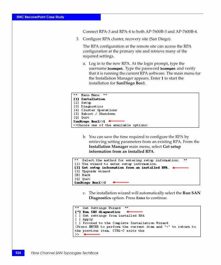
526
EMC RecoverPoint Case Study
Connect RPA-3 and RPA-4 to both AP-7600B-3 and AP-7600B-4.
3. Configure RPA cluster, recovery site (San Diego).
The RPA configuration at the remote site can access the RPA configuration at the primary site and retrieve many of the required settings.
a. Log in to the new RPA. At the login prompt, type the username boxmgmt. Type the password boxmgmt and verify that it is running the current RPA software. The main menu for the Installation Manager appears. Enter 1 to start the installation for SanDiego Box1.
b. You can save the time required to configure the RPA by retrieving setting parameters from an existing RPA. From the Installation Manager main menu, select Get setup information from an installed RPA.
c. The installation wizard will automatically select the Run SAN Diagnostics option. Press Enter to continue.
Fibre Channel SAN Topologies TechBook
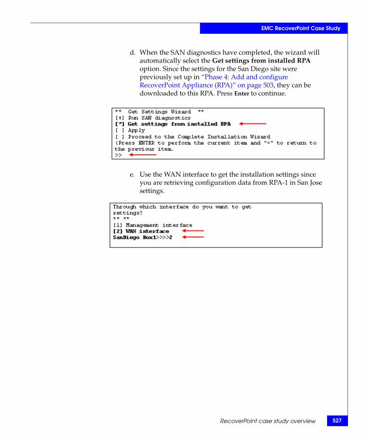
EMC RecoverPoint Case Study
d. When the SAN diagnostics have completed, the wizard will automatically select the Get settings from installed RPA option. Since the settings for the San Diego site were previously set up in “Phase 4: Add and configure RecoverPoint Appliance (RPA)” on page 503, they can be downloaded to this RPA. Press Enter to continue.
e. Use the WAN interface to get the installation settings since you are retrieving configuration data from RPA-1 in San Jose settings.
RecoverPoint case study overview 527
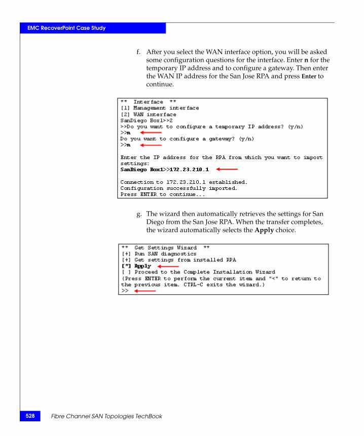
528
EMC RecoverPoint Case Study
f. After you select the WAN interface option, you will be asked some configuration questions for the interface. Enter n for the temporary IP address and to configure a gateway. Then enter the WAN IP address for the San Jose RPA and press Enter to continue.
g. The wizard then automatically retrieves the settings for San Diego from the San Jose RPA. When the transfer completes, the wizard automatically selects the Apply choice.
Fibre Channel SAN Topologies TechBook
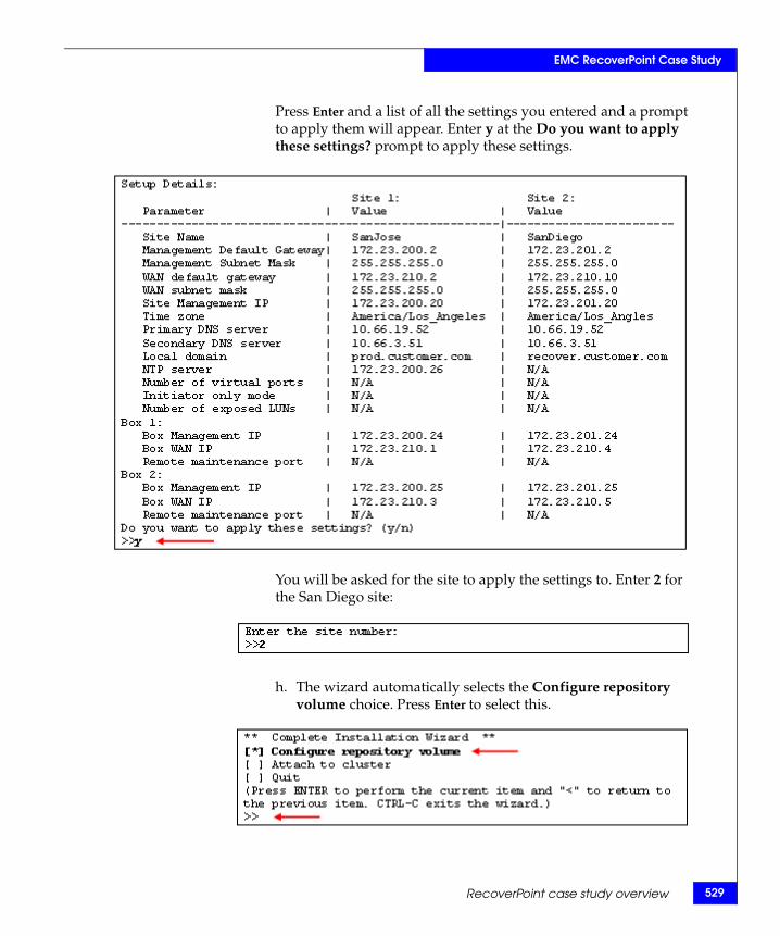
EMC RecoverPoint Case Study
Press Enter and a list of all the settings you entered and a prompt to apply them will appear. Enter y at the Do you want to apply these settings? prompt to apply these settings.
You will be asked for the site to apply the settings to. Enter 2 for the San Diego site:
h. The wizard automatically selects the Configure repository volume choice. Press Enter to select this.
RecoverPoint case study overview 529
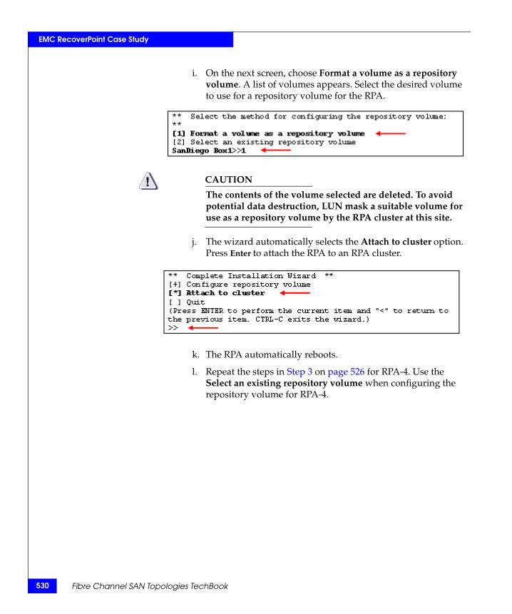
530
EMC RecoverPoint Case Study
i. On the next screen, choose Format a volume as a repository volume. A list of volumes appears. Select the desired volume to use for a repository volume for the RPA.
CAUTION!The contents of the volume selected are deleted. To avoid potential data destruction, LUN mask a suitable volume for use as a repository volume by the RPA cluster at this site.
j. The wizard automatically selects the Attach to cluster option. Press Enter to attach the RPA to an RPA cluster.
k. The RPA automatically reboots.
l. Repeat the steps in Step 3 on page 526 for RPA-4. Use the Select an existing repository volume when configuring the repository volume for RPA-4.
Fibre Channel SAN Topologies TechBook
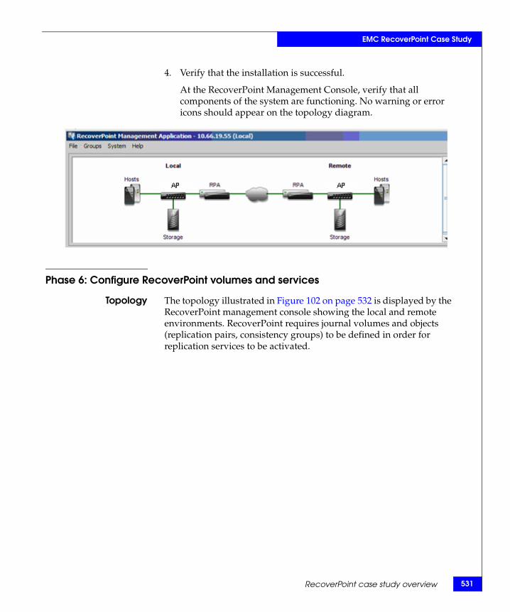
EMC RecoverPoint Case Study
4. Verify that the installation is successful.
At the RecoverPoint Management Console, verify that all components of the system are functioning. No warning or error icons should appear on the topology diagram.
Phase 6: Configure RecoverPoint volumes and services
Topology The topology illustrated in Figure 102 on page 532 is displayed by the RecoverPoint management console showing the local and remote environments. RecoverPoint requires journal volumes and objects (replication pairs, consistency groups) to be defined in order for replication services to be activated.
RecoverPoint case study overview 531
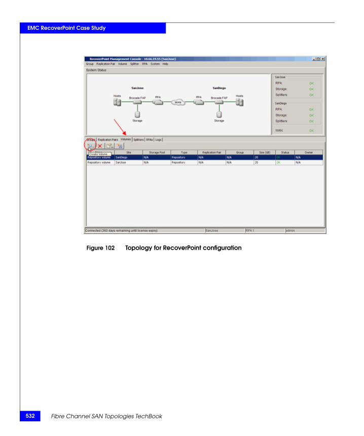
532
EMC RecoverPoint Case Study
Figure 102 Topology for RecoverPoint configuration
Fibre Channel SAN Topologies TechBook
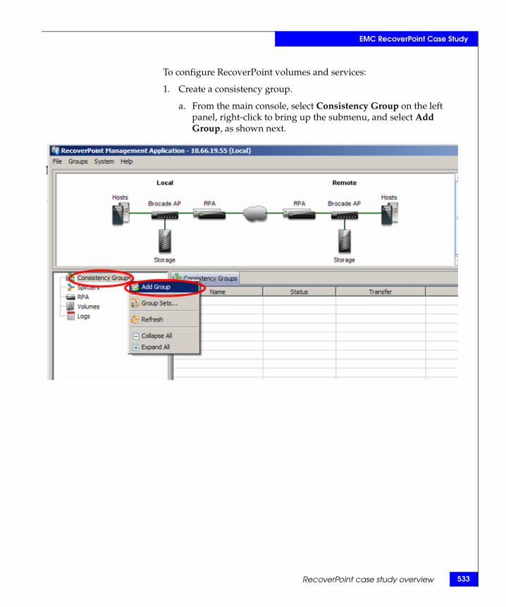
EMC RecoverPoint Case Study
To configure RecoverPoint volumes and services:
1. Create a consistency group.
a. From the main console, select Consistency Group on the left panel, right-click to bring up the submenu, and select Add Group, as shown next.
RecoverPoint case study overview 533
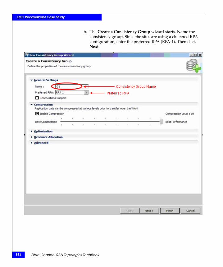
534
EMC RecoverPoint Case Study
b. The Create a Consistency Group wizard starts. Name the consistency group. Since the sites are using a clustered RPA configuration, enter the preferred RPA (RPA-1). Then click Next.
Fibre Channel SAN Topologies TechBook
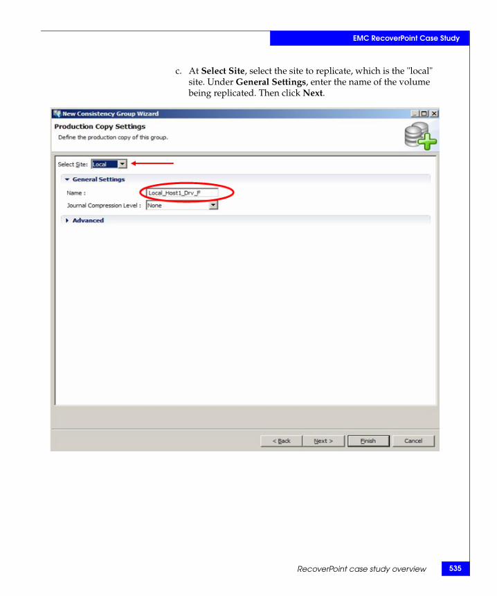
EMC RecoverPoint Case Study
c. At Select Site, select the site to replicate, which is the "local" site. Under General Settings, enter the name of the volume being replicated. Then click Next.
RecoverPoint case study overview 535
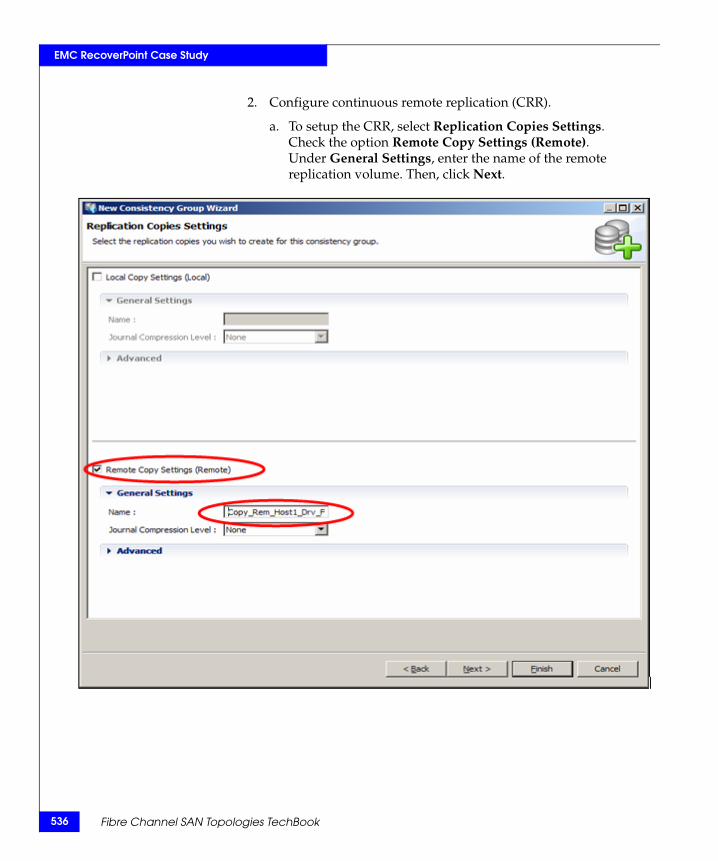
536
EMC RecoverPoint Case Study
2. Configure continuous remote replication (CRR).
a. To setup the CRR, select Replication Copies Settings. Check the option Remote Copy Settings (Remote). Under General Settings, enter the name of the remote replication volume. Then, click Next.
Fibre Channel SAN Topologies TechBook
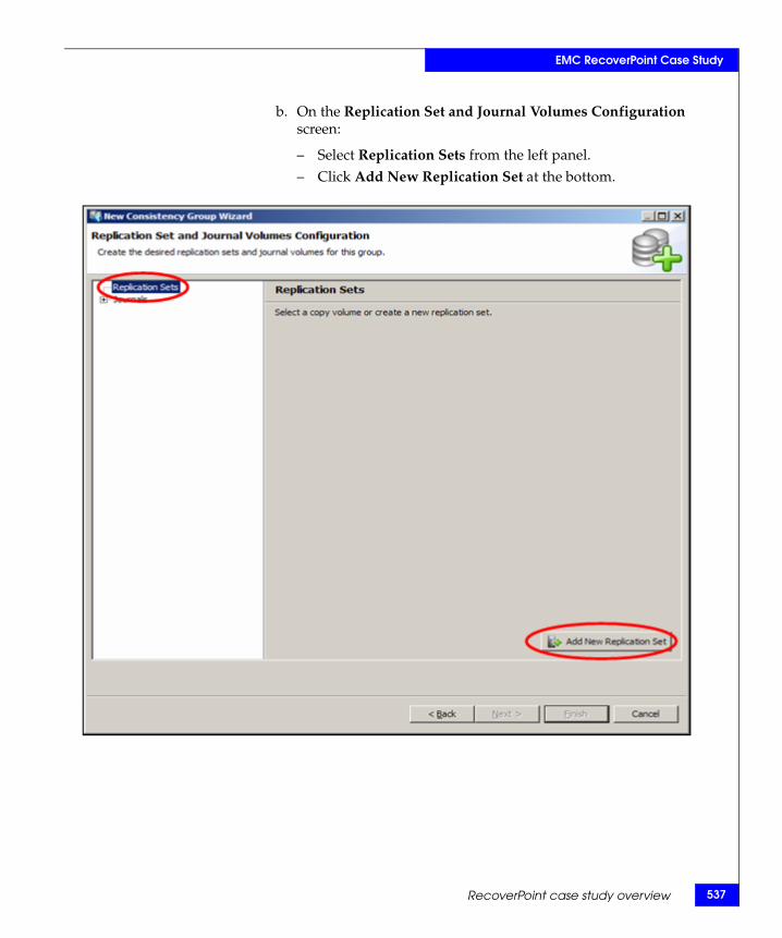
EMC RecoverPoint Case Study
b. On the Replication Set and Journal Volumes Configuration screen:
– Select Replication Sets from the left panel. – Click Add New Replication Set at the bottom.
RecoverPoint case study overview 537
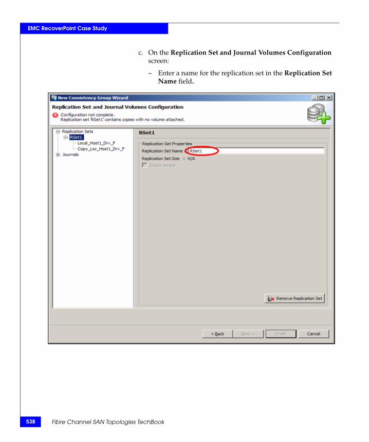
538
EMC RecoverPoint Case Study
c. On the Replication Set and Journal Volumes Configuration screen:
– Enter a name for the replication set in the Replication Set Name field.
Fibre Channel SAN Topologies TechBook
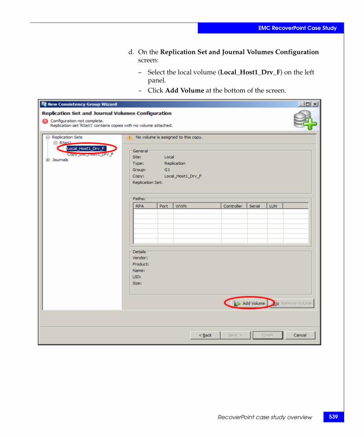
EMC RecoverPoint Case Study
d. On the Replication Set and Journal Volumes Configuration screen:
– Select the local volume (Local_Host1_Drv_F) on the left panel.
– Click Add Volume at the bottom of the screen.
RecoverPoint case study overview 539
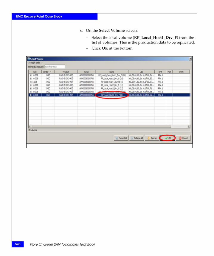
540
EMC RecoverPoint Case Study
e. On the Select Volume screen:
– Select the local volume (RP_Local_Host1_Drv_F) from the list of volumes. This is the production data to be replicated.
– Click OK at the bottom.
Fibre Channel SAN Topologies TechBook
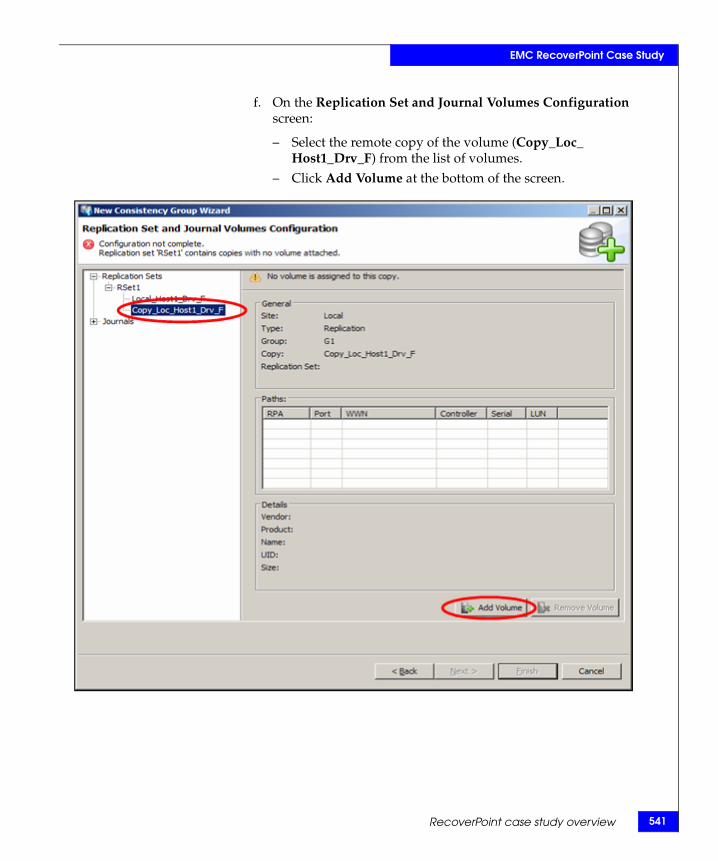
EMC RecoverPoint Case Study
f. On the Replication Set and Journal Volumes Configuration screen:
– Select the remote copy of the volume (Copy_Loc_ Host1_Drv_F) from the list of volumes.
– Click Add Volume at the bottom of the screen.
RecoverPoint case study overview 541
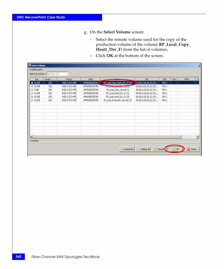
542
EMC RecoverPoint Case Study
g. On the Select Volume screen:
– Select the remote volume used for the copy of the production volume of the volume RP_Local_Copy_ Host1_Drv_F) from the list of volumes.
– Click OK at the bottom of the screen.
Fibre Channel SAN Topologies TechBook
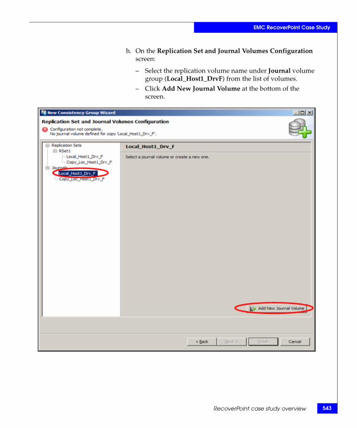
EMC RecoverPoint Case Study
h. On the Replication Set and Journal Volumes Configuration screen:
– Select the replication volume name under Journal volume group (Local_Host1_DrvF) from the list of volumes.
– Click Add New Journal Volume at the bottom of the screen.
RecoverPoint case study overview 543
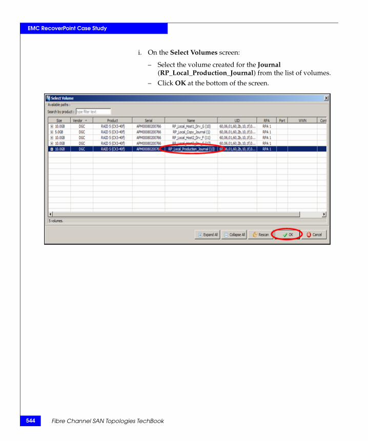
544
EMC RecoverPoint Case Study
i. On the Select Volumes screen:
– Select the volume created for the Journal (RP_Local_Production_Journal) from the list of volumes.
– Click OK at the bottom of the screen.
Fibre Channel SAN Topologies TechBook
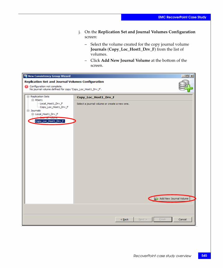
EMC RecoverPoint Case Study
j. On the Replication Set and Journal Volumes Configuration screen:
– Select the volume created for the copy journal volume Journals (Copy_Loc_Host1_Drv_F) from the list of volumes.
– Click Add New Journal Volume at the bottom of the screen.
RecoverPoint case study overview 545
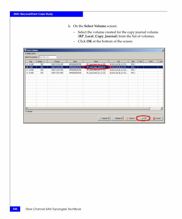
546
EMC RecoverPoint Case Study
k. On the Select Volume screen:
– Select the volume created for the copy journal volume (RP_Local_Copy_Journal) from the list of volumes.
– Click OK at the bottom of the screen.
Fibre Channel SAN Topologies TechBook
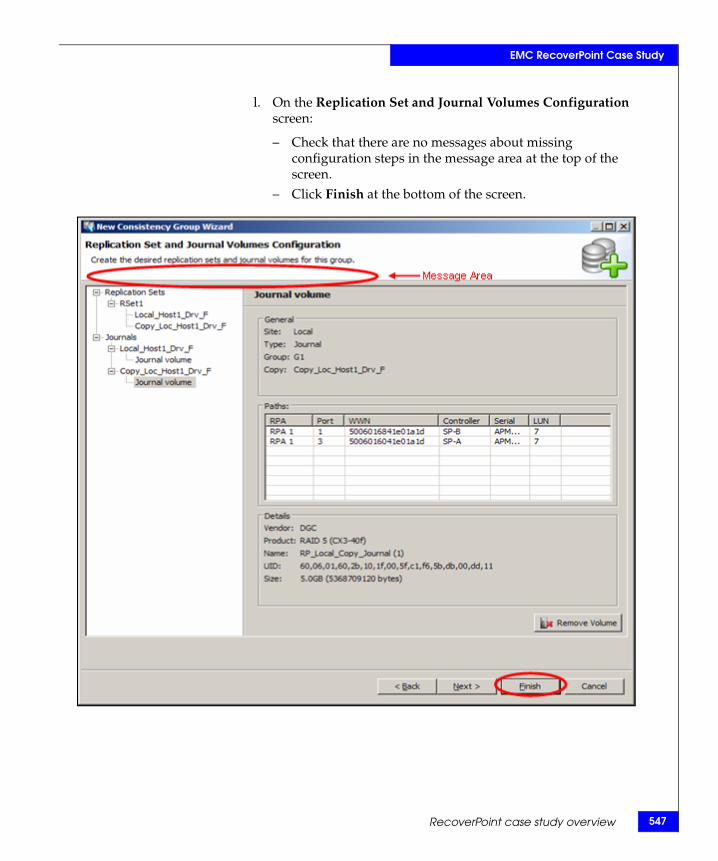
EMC RecoverPoint Case Study
l. On the Replication Set and Journal Volumes Configuration screen:
– Check that there are no messages about missing configuration steps in the message area at the top of the screen.
– Click Finish at the bottom of the screen.
RecoverPoint case study overview 547
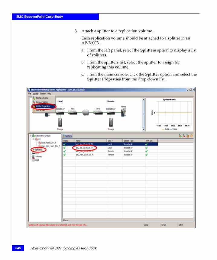
548
EMC RecoverPoint Case Study
3. Attach a splitter to a replication volume.
Each replication volume should be attached to a splitter in an AP-7600B.
a. From the left panel, select the Splitters option to display a list of splitters.
b. From the splitters list, select the splitter to assign for replicating this volume.
c. From the main console, click the Splitter option and select the Splitter Properties from the drop-down list.
Fibre Channel SAN Topologies TechBook
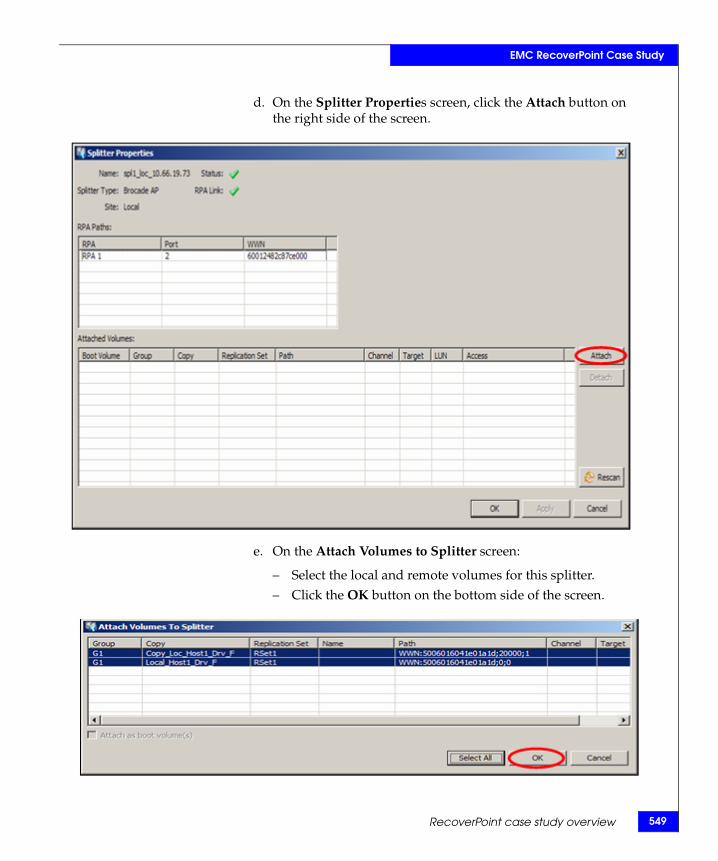
EMC RecoverPoint Case Study
d. On the Splitter Properties screen, click the Attach button on the right side of the screen.
e. On the Attach Volumes to Splitter screen:
– Select the local and remote volumes for this splitter.– Click the OK button on the bottom side of the screen.
RecoverPoint case study overview 549
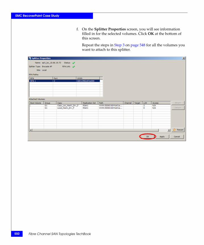
550
EMC RecoverPoint Case Study
f. On the Splitter Properties screen, you will see information filled in for the selected volumes. Click OK at the bottom of this screen.
Repeat the steps in Step 3 on page 548 for all the volumes you want to attach to this splitter.
Fibre Channel SAN Topologies TechBook
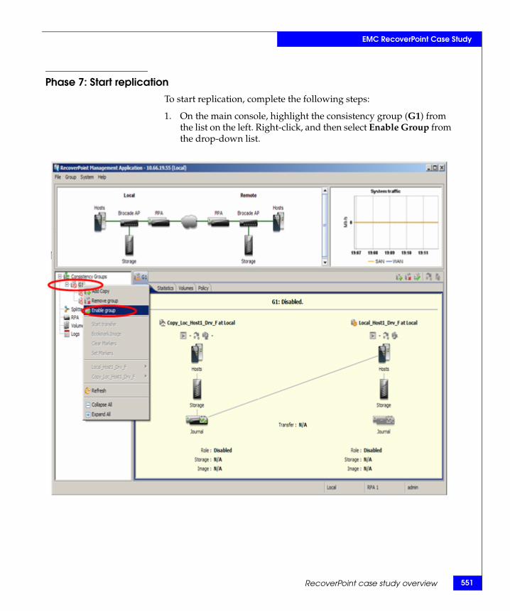
EMC RecoverPoint Case Study
Phase 7: Start replicationTo start replication, complete the following steps:
1. On the main console, highlight the consistency group (G1) from the list on the left. Right-click, and then select Enable Group from the drop-down list.
RecoverPoint case study overview 551
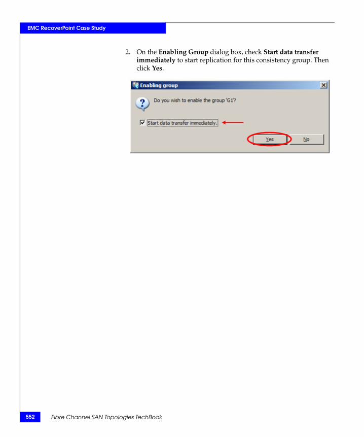
552
EMC RecoverPoint Case Study
2. On the Enabling Group dialog box, check Start data transfer immediately to start replication for this consistency group. Then click Yes.
Fibre Channel SAN Topologies TechBook
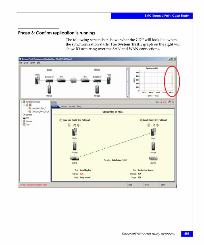
EMC RecoverPoint Case Study
Phase 8: Confirm replication is runningThe following screenshot shows what the CDP will look like when the synchronization starts. The System Traffic graph on the right will show IO occurring over the SAN and WAN connections.
RecoverPoint case study overview 553
554
EMC RecoverPoint Case Study
Implementing a scalable core-edge topologyThis section includes the following information to implement a scalable core-edge topology:
◆ “Overview of scalable core-edge architecture” on page 554
◆ “Scalable core-edge fabric design” on page 554
◆ “Scalable core-edge” on page 557
Overview of scalable core-edge architectureAs discussed in "Fabric design considerations and recommendations" in the Networked Storage Concepts and Protocols TechBook, available through the E-Lab Interoperability Navigator, Topology Resource Center tab, at http://elabnavigator.EMC.com, for highly-scalable fabrics, the predominant SAN deployments are redundant core-edge fabric topologies, using high-density components to reduce fabric complexity and minimize ports consumed for ISLs. The advantages of core-edge fabric designs are:
◆ Predictable traffic flows
◆ Minimal hop counts and ports allocated for ISLs to provide the needed bandwidth between the switches in the fabric
With the availability of the ED-DCX-B, the design options for an enterprise SAN topology are broadened. Leveraging the ED-DCX-B makes it possible to design SAN fabrics with unprecedented scalability and performance.
This section describes a solution using the ED-DCX-B. The solution is based on identical dual-redundant fabrics; therefore we will only discuss one fabric.
Scalable core-edge fabric design
The scalable core-edge fabric design follows a single core fabric architecture. In phases, the fabric can be expanded by expanding the core and adding edge switches.
Fibre Channel SAN Topologies TechBook
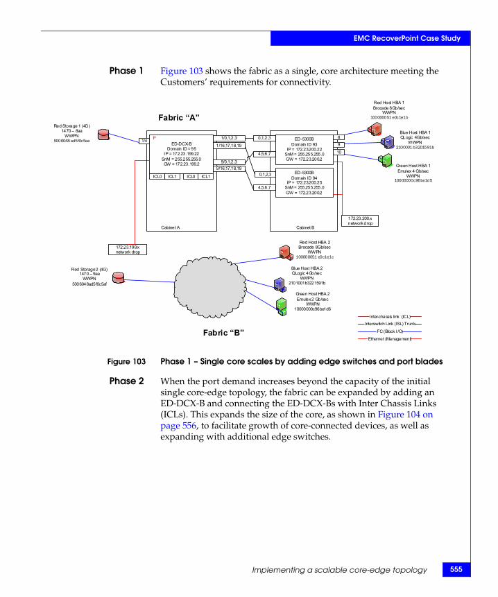
EMC RecoverPoint Case Study
Phase 1 Figure 103 shows the fabric as a single, core architecture meeting the Customers’ requirements for connectivity.
Figure 103 Phase 1 – Single core scales by adding edge switches and port blades
Phase 2 When the port demand increases beyond the capacity of the initial single core-edge topology, the fabric can be expanded by adding an ED-DCX-B and connecting the ED-DCX-Bs with Inter Chassis Links (ICLs). This expands the size of the core, as shown in Figure 104 on page 556, to facilitate growth of core-connected devices, as well as expanding with additional edge switches.
ED-DCX-BDomain ID = 95
IP = 172.23.199.22SnM = 255.255.255.0GW = 172.23.199.2
ED-5300BDomain ID 94
IP = 172.23.200.25SnM = 255.255.255.0GW = 172.23.200.2
ED-5300BDomain ID 93
IP = 172.23.200.22SnM = 255.255.255.0GW = 172.23.200.2
172.23.199.x network drop
FC (Block I /O)
Ethernet (Management)
Interswitch Link (ISL) Trunk
Cabinet A Cabinet B
172.23.200.x network drop
Red Host HBA 1Brocade 8Gb/sec
WWPN100000051 e0c1e1b
Red Host HBA 2Brocade 8Gb/sec
WWPN100000051 e0c1e1c
Green Host HBA 1Emulex 4 Gb/sec
WWPN10000000c96be1d5
Green Host HBA 2Emulex 2 Gb/sec
WWPN10000000c96be1d6
Blue Host HBA 1QLogic 4Gb/sec
WWPN2100001 b3201591b
Blue Host HBA 2QLogic 4Gb/sec
WWPN2101001b3221591b
Red Storage 2 (4G)1470 – 9aa
WWPN5006048ad5f0c5af
Red Storage 1 (4G)1470 – 8aa
WWPN5006048 ad5f0c5ae 1/0,1,2,3
ICL0 ICL1
4,5,6,7
0,1,2,39/16,17,18,19
1/16,17,18,191/4
8P 0,1,2,3
4,5,6,7
9/0,1,2,3
ICL1
Inter-chassis link (ICL)
ICL0
9
10
Fabric “A”
Fabric “B”
Implementing a scalable core-edge topology 555
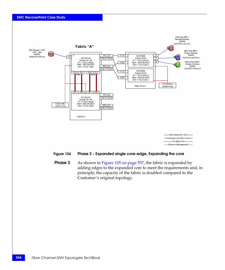
556
EMC RecoverPoint Case Study
Figure 104 Phase 2 – Expanded single core-edge, Expanding the core
Phase 3 As shown in Figure 105 on page 557, the fabric is expanded by adding edges to the expanded core to meet the requirements and, in principle, the capacity of the fabric is doubled compared to the Customer’s original topology.
ED-DCX-BDomain ID = 95
IP = 172.23.199.22SnM = 255.255.255.0GW = 172.23.199.2
ED-DCX-BDomain ID = 96
IP = 172.23.199.25SnM = 255.255.255.0GW = 172.23.199.2
ED-5300BDomain ID 94
IP = 172.23.200.25SnM = 255.255.255.0GW = 172.23.200.2
ED-5300BDomain ID 93
IP = 172.23.200.22SnM = 255.255.255.0GW = 172.23.200.2
172.23.199.x network drop
FC (Block I /O)Ethernet (Management)
Interswitch Link (ISL) Trunk
Cabinet A
Edge Group 1172.23.200.x network drop
Red Host HBA 1Brocade 8Gb/sec
WWPN100000051 e0c1e1b
Green Host HBA 1Emulex 4 Gb/sec
WWPN10000000 c96be1d5
Blue Host HBA 1QLogic 4Gb/sec
WWPN2100001b3201591b
Red Storage 1 (4G)1470 – 8aa
WWPN5006048ad5f0c5ae 1/0,1,2,3
ICL1 ICL0
ICL0 ICL1
4,5,6,7
0,1,2,39/16,17,18,19
1/16,17,18,191/4
8P 0,1,2,3
4,5,6,7
9/0,1,2,3
ICL1
ICL0
Slot5 Slot8
Inter-chassis link (ICL)
ICL0
ICL1
910
Fabric “A”
1/0,1,2,3
9/16,17,18,19
1/16,17,18,19
9/0,1,2,3
Fibre Channel SAN Topologies TechBook
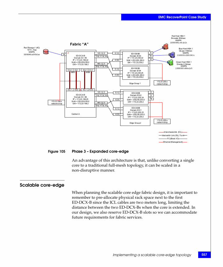
EMC RecoverPoint Case Study
Figure 105 Phase 3 – Expanded core-edge
An advantage of this architecture is that, unlike converting a single core to a traditional full-mesh topology, it can be scaled in a non-disruptive manner.
Scalable core-edge
When planning the scalable core edge fabric design, it is important to remember to pre-allocate physical rack space next to the first ED-DCX-B since the ICL cables are two meters long, limiting the distance between the two ED-DCX-Bs when the core is extended. In our design, we also reserve ED-DCX-B slots so we can accommodate future requirements for fabric services.
ED-DCX-BDomain ID = 95
IP = 172.23.199.22SnM = 255.255.255.0GW = 172.23.199.2
ED-DCX-BDomain ID = 96
IP = 172.23.199.25SnM = 255.255.255.0GW = 172.23.199.2
ED-5300BDomain ID 94
IP = 172.23.200.25SnM = 255.255.255.0GW = 172.23.200.2
ED-5300BDomain ID 93
IP = 172.23.200.22SnM = 255.255.255.0GW = 172.23.200.2
172.23.199.x network drop
FC (Block I /O)
Ethernet (Management)
Interswitch Link (ISL) Trunk
Cabinet A
Edge Group 1172.23.200.x network drop
Red Host HBA 1Brocade 8Gb/sec
WWPN100000051 e0c1e1b
Green Host HBA 1Emulex 4 Gb/sec
WWPN10000000 c96be1d5
Blue Host HBA 1QLogic 4Gb/sec
WWPN2100001b3201591 b
Red Storage 1 (4G)1470 – 8aa
WWPN5006048 ad5f0c5ae 1/0,1,2,3
ICL1 ICL0
ICL0 ICL1
4,5,6,7
0,1,2,39/16,17,18,19
1/16,17,18,191/4
8P 0,1,2,3
4,5,6,7
9/0,1,2,3
ICL1
ICL0
Slot5 Slot8
Inter-chassis link (ICL)
ICL0
ICL1
9
10
Fabric “A”
1/0,1,2,3
9/16,17,18,19
1/16,17,18,19
9/0,1,2,3
ED-5300BDomain ID 91
IP = 172.23.200.23SnM = 255.255.255.0GW = 172.23.200.2
ED-5300BDomain ID 92
IP = 172.23.200.24SnM = 255.255.255.0GW = 172.23.200.2
Edge Group 2
4,5,6,7
0,1,2,3
80,1,2,3
4,5,6,7
910
172.23.200.x network drop
Implementing a scalable core-edge topology 557
558
EMC RecoverPoint Case Study
Deploying a scalable core-edge SAN topology
Chronology of activities
◆ Assessment, planning, design
◆ Deployment
• Deploy management tools: EMC Connectrix Manager Data Center Edition
– Element Setup(defzone –no access)• Connect switches
• Finalizing/forming fabric
• Device connect
– Zoning• On-going administration
– Add device, zoning changes• Scaling –expanding
– Add (port) blade– Add switch
• Upgrade FOS
Prerequisites
◆ The ED-DCX-B should be configured with IP addresses as discussed in the EMC Connectrix B Series ED-DCX-B Hardware Reference Manual
• The ED-DCX-B platform requires three IP addresses
– One for each of the two CPs – One for the logical switch
◆ A computer with Ethernet network capability and telnet utility (such as, putty) to access switch CLI commands
• The EMC Connectrix Manager Data Center server can be used for this purpose
◆ EMC Connectrix Manager Data Center license for FOS products
Assumptions
◆ EMC Connectrix Manager Data Center Edition server (latest GA release) is used
◆ Ensure the required FOS feature licenses are available
Fibre Channel SAN Topologies TechBook
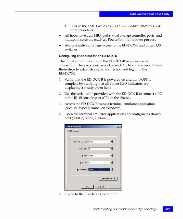
EMC RecoverPoint Case Study
• Refer to the EMC Connectrix B FOS 6.1.x Administrator's Guide for more details
◆ All hosts have dual HBA paths, dual storage controller ports, and multipath software (such as, PowerPath) for failover purpose
◆ Administrative privilege access to the ED-DCX-B and other FOS switches
Configuring IP address for an ED-DCX-B
The initial communication to the ED-DCX-B requires a serial connection. There is a console port on each CP to allow access. Follow these steps to establish a serial connection and log in to the ED-DCX-B.
1. Verify that the ED-DCX-B is powered on and that POST is complete by verifying that all power LED indicators are displaying a steady green light.
2. Use the serial cable provided with the ED-DCX-B to connect a PC to the RJ-45 console port (CP) on the chassis.
3. Access the ED-DCX-B using a terminal emulator application (such as HyperTerminal on Windows).
4. Open the terminal emulator application and configure as shown next (9600, 8, None, 1, None.)
5. Log in to the ED-DCX-B as "admin".
Implementing a scalable core-edge topology 559
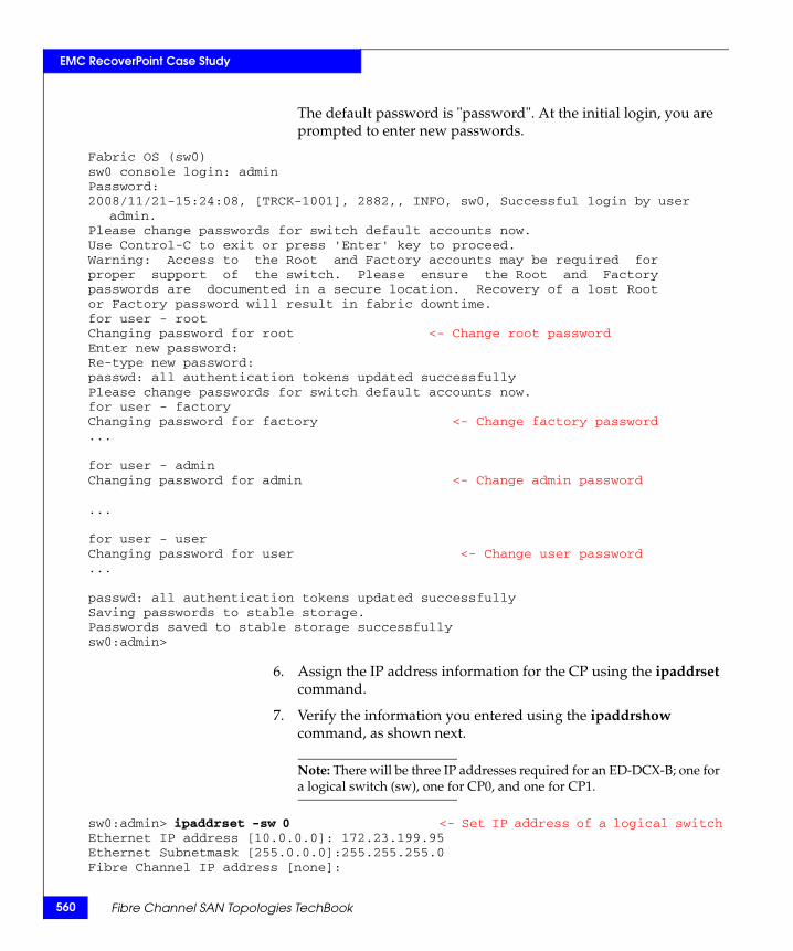
560
EMC RecoverPoint Case Study
The default password is "password". At the initial login, you are prompted to enter new passwords.
Fabric OS (sw0)sw0 console login: adminPassword: 2008/11/21-15:24:08, [TRCK-1001], 2882,, INFO, sw0, Successful login by user
admin.Please change passwords for switch default accounts now.Use Control-C to exit or press 'Enter' key to proceed.Warning: Access to the Root and Factory accounts may be required forproper support of the switch. Please ensure the Root and Factorypasswords are documented in a secure location. Recovery of a lost Rootor Factory password will result in fabric downtime.for user - root Changing password for root <- Change root password Enter new password:Re-type new password:passwd: all authentication tokens updated successfullyPlease change passwords for switch default accounts now.for user - factoryChanging password for factory <- Change factory password...
for user - adminChanging password for admin <- Change admin password
...
for user - userChanging password for user <- Change user password...
passwd: all authentication tokens updated successfullySaving passwords to stable storage.Passwords saved to stable storage successfullysw0:admin>
6. Assign the IP address information for the CP using the ipaddrset command.
7. Verify the information you entered using the ipaddrshow command, as shown next.
Note: There will be three IP addresses required for an ED-DCX-B; one for a logical switch (sw), one for CP0, and one for CP1.
sw0:admin> ipaddrset -sw 0 <- Set IP address of a logical switchEthernet IP address [10.0.0.0]: 172.23.199.95Ethernet Subnetmask [255.0.0.0]:255.255.255.0Fibre Channel IP address [none]:
Fibre Channel SAN Topologies TechBook
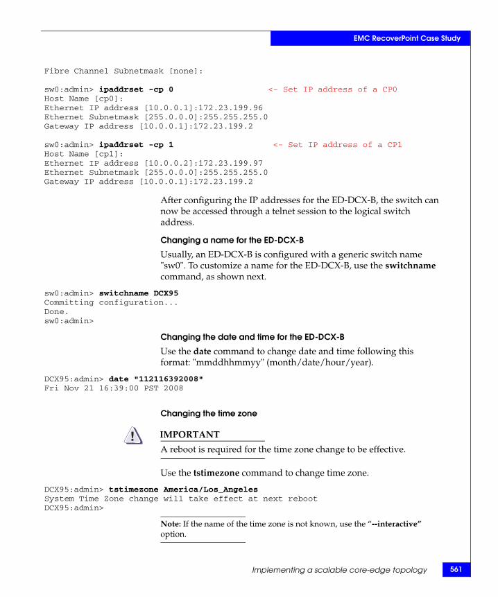
EMC RecoverPoint Case Study
Fibre Channel Subnetmask [none]:
sw0:admin> ipaddrset -cp 0 <- Set IP address of a CP0Host Name [cp0]:Ethernet IP address [10.0.0.1]:172.23.199.96Ethernet Subnetmask [255.0.0.0]:255.255.255.0Gateway IP address [10.0.0.1]:172.23.199.2
sw0:admin> ipaddrset -cp 1 <- Set IP address of a CP1Host Name [cp1]:Ethernet IP address [10.0.0.2]:172.23.199.97Ethernet Subnetmask [255.0.0.0]:255.255.255.0Gateway IP address [10.0.0.1]:172.23.199.2
After configuring the IP addresses for the ED-DCX-B, the switch can now be accessed through a telnet session to the logical switch address.
Changing a name for the ED-DCX-B
Usually, an ED-DCX-B is configured with a generic switch name "sw0". To customize a name for the ED-DCX-B, use the switchname command, as shown next.
sw0:admin> switchname DCX95Committing configuration...Done.sw0:admin>
Changing the date and time for the ED-DCX-B
Use the date command to change date and time following this format: "mmddhhmmyy" (month/date/hour/year).
DCX95:admin> date "112116392008"Fri Nov 21 16:39:00 PST 2008
Changing the time zone
IMPORTANT!A reboot is required for the time zone change to be effective.
Use the tstimezone command to change time zone.
DCX95:admin> tstimezone America/Los_AngelesSystem Time Zone change will take effect at next rebootDCX95:admin>
Note: If the name of the time zone is not known, use the “--interactive” option.
Implementing a scalable core-edge topology 561
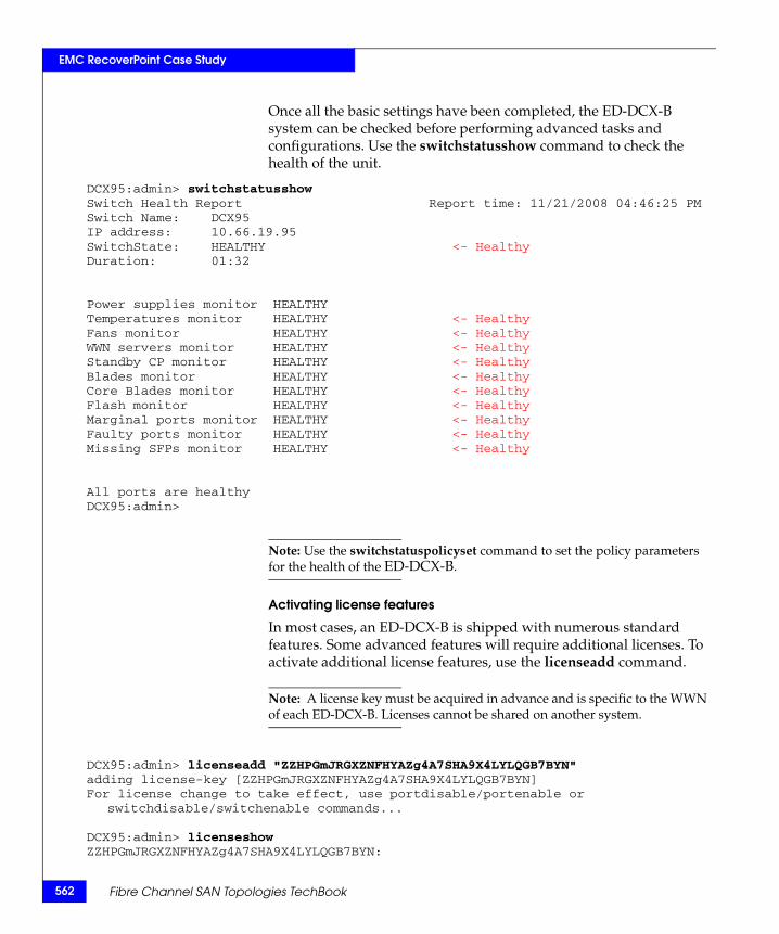
562
EMC RecoverPoint Case Study
Once all the basic settings have been completed, the ED-DCX-B system can be checked before performing advanced tasks and configurations. Use the switchstatusshow command to check the health of the unit.
DCX95:admin> switchstatusshowSwitch Health Report Report time: 11/21/2008 04:46:25 PMSwitch Name: DCX95IP address: 10.66.19.95SwitchState: HEALTHY <- HealthyDuration: 01:32
Power supplies monitor HEALTHYTemperatures monitor HEALTHY <- HealthyFans monitor HEALTHY <- HealthyWWN servers monitor HEALTHY <- HealthyStandby CP monitor HEALTHY <- HealthyBlades monitor HEALTHY <- HealthyCore Blades monitor HEALTHY <- HealthyFlash monitor HEALTHY <- HealthyMarginal ports monitor HEALTHY <- HealthyFaulty ports monitor HEALTHY <- HealthyMissing SFPs monitor HEALTHY <- Healthy
All ports are healthyDCX95:admin>
Note: Use the switchstatuspolicyset command to set the policy parameters for the health of the ED-DCX-B.
Activating license features
In most cases, an ED-DCX-B is shipped with numerous standard features. Some advanced features will require additional licenses. To activate additional license features, use the licenseadd command.
Note: A license key must be acquired in advance and is specific to the WWN of each ED-DCX-B. Licenses cannot be shared on another system.
DCX95:admin> licenseadd "ZZHPGmJRGXZNFHYAZg4A7SHA9X4LYLQGB7BYN"adding license-key [ZZHPGmJRGXZNFHYAZg4A7SHA9X4LYLQGB7BYN]For license change to take effect, use portdisable/portenable or
switchdisable/switchenable commands...
DCX95:admin> licenseshowZZHPGmJRGXZNFHYAZg4A7SHA9X4LYLQGB7BYN:
Fibre Channel SAN Topologies TechBook
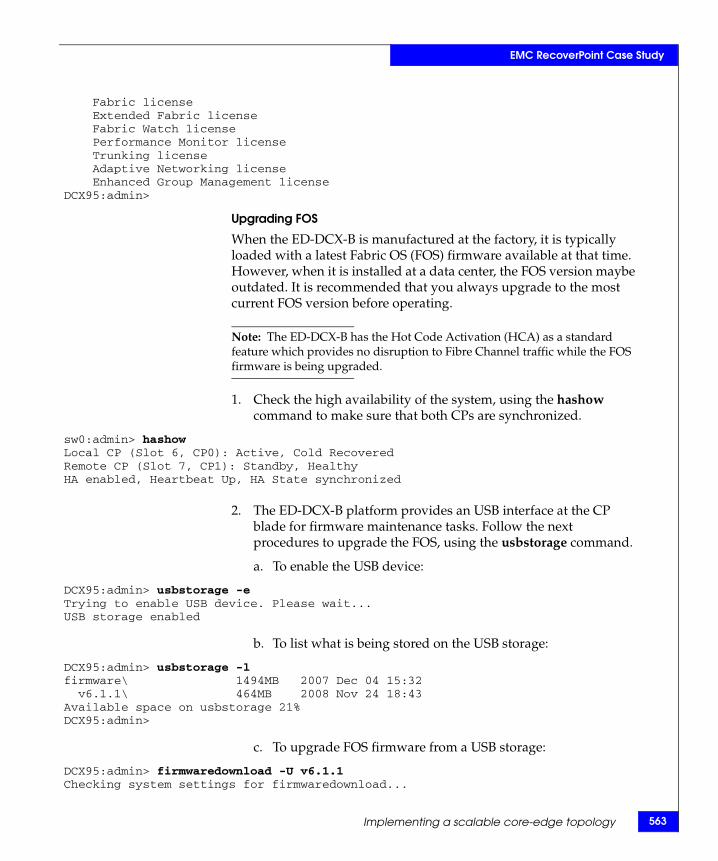
EMC RecoverPoint Case Study
Fabric license Extended Fabric license Fabric Watch license Performance Monitor license Trunking license Adaptive Networking license Enhanced Group Management licenseDCX95:admin>
Upgrading FOS
When the ED-DCX-B is manufactured at the factory, it is typically loaded with a latest Fabric OS (FOS) firmware available at that time. However, when it is installed at a data center, the FOS version maybe outdated. It is recommended that you always upgrade to the most current FOS version before operating.
Note: The ED-DCX-B has the Hot Code Activation (HCA) as a standard feature which provides no disruption to Fibre Channel traffic while the FOS firmware is being upgraded.
1. Check the high availability of the system, using the hashow command to make sure that both CPs are synchronized.
sw0:admin> hashowLocal CP (Slot 6, CP0): Active, Cold RecoveredRemote CP (Slot 7, CP1): Standby, Healthy HA enabled, Heartbeat Up, HA State synchronized
2. The ED-DCX-B platform provides an USB interface at the CP blade for firmware maintenance tasks. Follow the next procedures to upgrade the FOS, using the usbstorage command.
a. To enable the USB device:
DCX95:admin> usbstorage -eTrying to enable USB device. Please wait...USB storage enabled
b. To list what is being stored on the USB storage:
DCX95:admin> usbstorage -lfirmware\ 1494MB 2007 Dec 04 15:32 v6.1.1\ 464MB 2008 Nov 24 18:43Available space on usbstorage 21%DCX95:admin>
c. To upgrade FOS firmware from a USB storage:
DCX95:admin> firmwaredownload -U v6.1.1Checking system settings for firmwaredownload...
Implementing a scalable core-edge topology 563
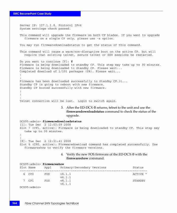
564
EMC RecoverPoint Case Study
Server IP: 127.1.1.8, Protocol IPv4System settings check passed.
This command will upgrade the firmware on both CP blades. If you want to upgrade firmware on a single CP only, please use -s option.
You may run firmwaredownloadstatus to get the status of this command.
This command will cause a warm/non-disruptive boot on the active CP, but will require that existing telnet, secure telnet or SSH sessions be restarted.
Do you want to continue [Y]: YFirmware is being downloaded to standby CP. This step may take up to 30 minutes.Firmware is being downloaded to Standby CP. Please wait...Completed download of 1/101 packages (0%). Please wait...::Firmware has been downloaded successfully to Standby CP.it...Standby CP is going to reboot with new firmware.Standby CP booted successfully with new firmware.:::Telnet connection will be lost. Login to switch again.
3. After the ED-DCX-B returns, telnet to the unit and use the firmwaredownloadstatus command to check the status of the upgrade.
DCX95:admin> firmwaredownloadstatus[1]: Tue Dec 2 12:03:09 2008Slot 7 (CP1, active): Firmware is being downloaded to standby CP. This step may
take up to 30 minutes.::[8]: Tue Dec 2 12:31:41 2008Slot 6 (CP0, active): Firmwaredownload command has completed successfully. Use
firmwareshow to verify the firmware versions.
4. Verify the new FOS firmware of the ED-DCX-B with the firmwareshow command.
DCX95:admin> firmwareshowSlot Name Appl Primary/Secondary Versions Status------------------------------------------------------------------------ 6 CP0 FOS v6.1.1 ACTIVE * v6.1.1 7 CP1 FOS v6.1.1 STANDBY v6.1.1DCX95:admin>
Fibre Channel SAN Topologies TechBook
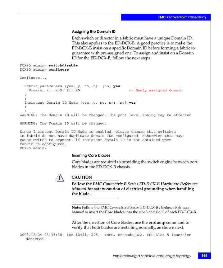
EMC RecoverPoint Case Study
Assigning the Domain ID
Each switch or director in a fabric must have a unique Domain ID. This also applies to the ED-DCX-B. A good practice is to make the ED-DCX-B insist on a specific Domain ID before forming a fabric to guarantee with pre-assigned one. To assign and insist on a Domain ID for the ED-DCX-B, follow the next steps.
DCX95:admin> switchdisableDCX95:admin> configure
Configure...
Fabric parameters (yes, y, no, n): [no] yes Domain: (1..239) [1] 95 <- Newly assigned domain : : Insistent Domain ID Mode (yes, y, no, n): [no] yes : :WARNING: The domain ID will be changed. The port level zoning may be affected
WARNING: The Domain ID will be changed.
Since Insistent Domain ID Mode is enabled, please ensure that switchesin fabric do not have duplicate domain IDs configured, otherwise this maycause switch to segment, if Insistent domain ID is not obtained whenfabric re-configures.DCX95:admin>
Inserting Core blades
Core blades are required to providing the switch engine between port blades in the ED-DCX-B chassis.
CAUTION!Follow the EMC Connectrix B Series ED-DCX-B Hardware Reference Manual for safety caution of electrical grounding when handling the blade.
Note: Follow the EMC Connectrix B Series ED-DCX-B Hardware Reference Manual to insert the Core blades into the slot 5 and slot 8 of each ED-DCX-B.
After the insertion of Core blades, use the errdump command to verify that both blades are installing normally, as shown next.
2008/12/04-23:33:38, [EM-1049], 295,, INFO, Brocade_DCX, FRU Slot 5 insertion detected.
Implementing a scalable core-edge topology 565
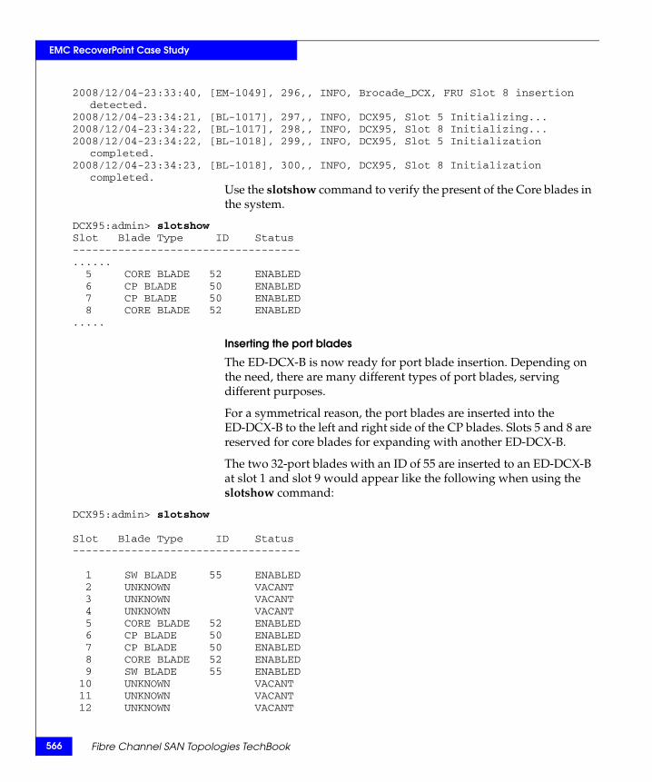
566
EMC RecoverPoint Case Study
2008/12/04-23:33:40, [EM-1049], 296,, INFO, Brocade_DCX, FRU Slot 8 insertion detected.
2008/12/04-23:34:21, [BL-1017], 297,, INFO, DCX95, Slot 5 Initializing...2008/12/04-23:34:22, [BL-1017], 298,, INFO, DCX95, Slot 8 Initializing...2008/12/04-23:34:22, [BL-1018], 299,, INFO, DCX95, Slot 5 Initialization
completed.2008/12/04-23:34:23, [BL-1018], 300,, INFO, DCX95, Slot 8 Initialization
completed.Use the slotshow command to verify the present of the Core blades in the system.
DCX95:admin> slotshowSlot Blade Type ID Status-----------------------------------...... 5 CORE BLADE 52 ENABLED 6 CP BLADE 50 ENABLED 7 CP BLADE 50 ENABLED 8 CORE BLADE 52 ENABLED.....
Inserting the port blades
The ED-DCX-B is now ready for port blade insertion. Depending on the need, there are many different types of port blades, serving different purposes.
For a symmetrical reason, the port blades are inserted into the ED-DCX-B to the left and right side of the CP blades. Slots 5 and 8 are reserved for core blades for expanding with another ED-DCX-B.
The two 32-port blades with an ID of 55 are inserted to an ED-DCX-B at slot 1 and slot 9 would appear like the following when using the slotshow command:
DCX95:admin> slotshow
Slot Blade Type ID Status-----------------------------------
1 SW BLADE 55 ENABLED 2 UNKNOWN VACANT 3 UNKNOWN VACANT 4 UNKNOWN VACANT 5 CORE BLADE 52 ENABLED 6 CP BLADE 50 ENABLED 7 CP BLADE 50 ENABLED 8 CORE BLADE 52 ENABLED 9 SW BLADE 55 ENABLED 10 UNKNOWN VACANT 11 UNKNOWN VACANT 12 UNKNOWN VACANT
Fibre Channel SAN Topologies TechBook
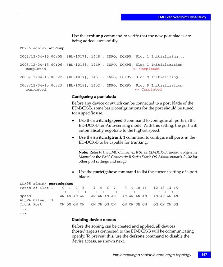
EMC RecoverPoint Case Study
Use the errdump command to verify that the new port blades are being added successfully.
DCX95:admin> errdump:2008/12/04-15:00:05, [BL-1017], 1448,, INFO, DCX95, Slot 1 Initializing...
2008/12/04-15:00:06, [BL-1018], 1449,, INFO, DCX95, Slot 1 Initialization completed. <- Completed
:2008/12/04-15:00:22, [BL-1017], 1451,, INFO, DCX95, Slot 9 Initializing...
2008/12/04-15:00:23, [BL-1018], 1452,, INFO, DCX95, Slot 9 Initialization completed. <- Completed
Configuring a port blade
Before any device or switch can be connected to a port blade of the ED-DCX-B, some basic configurations for the port should be tuned for a specific use.
◆ Use the switchcfgspeed 0 command to configure all ports in the ED-DCX-B for Auto-sensing mode. With this setting, the port will automatically negotiate to the highest speed.
◆ Use the switchcfgtrunk 1 command to configure all ports in the ED-DCX-B to be capable for trunking.
Note: Refer to the EMC Connectrix B Series ED-DCX-B Hardware Reference Manual or the EMC Connectrix B Series Fabric OS Administrator’s Guide for other port settings and usage.
◆ Use the portcfgshow command to list the current setting of a port blade.
DCX95:admin> portcfgshowPorts of Slot 1 0 1 2 3 4 5 6 7 8 9 10 11 12 13 14 15-----------------+--+--+--+--+----+--+--+--+----+--+--+--+----+--+--+--Speed AN AN AN AN AN AN AN AN AN AN AN AN AN AN AN ANAL_PA Offset 13 .. .. .. .. .. .. .. .. .. .. .. .. .. .. .. ..Trunk Port ON ON ON ON ON ON ON ON ON ON ON ON ON ON ON ON......
Disabling device access
Before the zoning can be created and applied, all devices (hosts/targets) connected to the ED-DCX-B will be communicating openly. To prevent this, use the defzone command to disable the devise access, as shown next.
Implementing a scalable core-edge topology 567
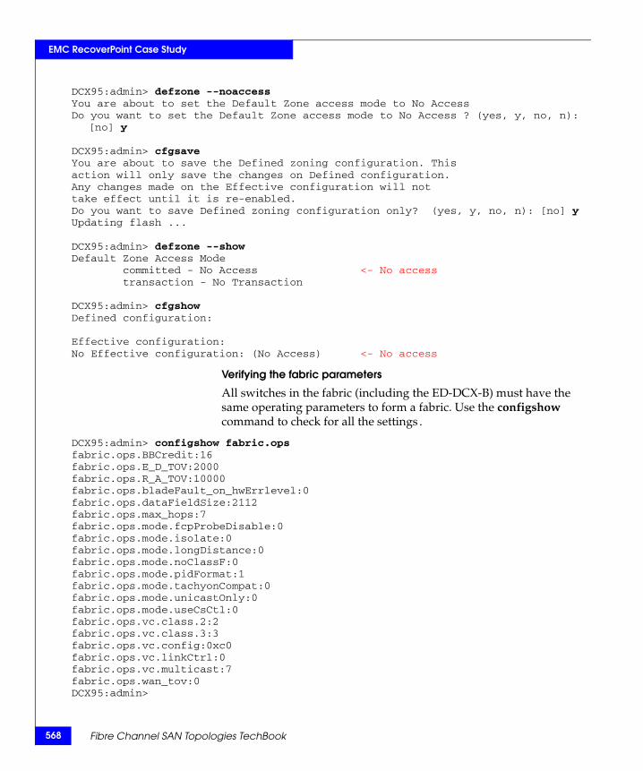
568
EMC RecoverPoint Case Study
DCX95:admin> defzone --noaccessYou are about to set the Default Zone access mode to No AccessDo you want to set the Default Zone access mode to No Access ? (yes, y, no, n):
[no] y
DCX95:admin> cfgsaveYou are about to save the Defined zoning configuration. Thisaction will only save the changes on Defined configuration.Any changes made on the Effective configuration will nottake effect until it is re-enabled.Do you want to save Defined zoning configuration only? (yes, y, no, n): [no] yUpdating flash ...
DCX95:admin> defzone --showDefault Zone Access Mode committed - No Access <- No access transaction - No Transaction
DCX95:admin> cfgshowDefined configuration:
Effective configuration:No Effective configuration: (No Access) <- No access
Verifying the fabric parameters
All switches in the fabric (including the ED-DCX-B) must have the same operating parameters to form a fabric. Use the configshow command to check for all the settings.
DCX95:admin> configshow fabric.opsfabric.ops.BBCredit:16fabric.ops.E_D_TOV:2000fabric.ops.R_A_TOV:10000fabric.ops.bladeFault_on_hwErrlevel:0fabric.ops.dataFieldSize:2112fabric.ops.max_hops:7fabric.ops.mode.fcpProbeDisable:0fabric.ops.mode.isolate:0fabric.ops.mode.longDistance:0fabric.ops.mode.noClassF:0fabric.ops.mode.pidFormat:1fabric.ops.mode.tachyonCompat:0fabric.ops.mode.unicastOnly:0fabric.ops.mode.useCsCtl:0fabric.ops.vc.class.2:2fabric.ops.vc.class.3:3fabric.ops.vc.config:0xc0fabric.ops.vc.linkCtrl:0fabric.ops.vc.multicast:7fabric.ops.wan_tov:0DCX95:admin>
Fibre Channel SAN Topologies TechBook
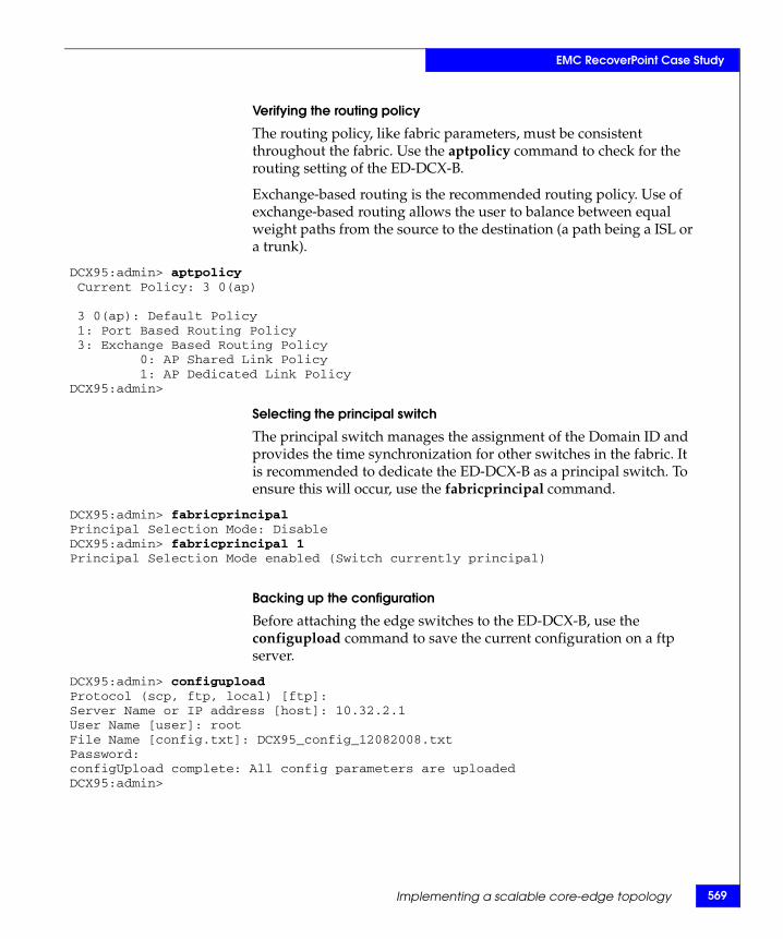
EMC RecoverPoint Case Study
Verifying the routing policy
The routing policy, like fabric parameters, must be consistent throughout the fabric. Use the aptpolicy command to check for the routing setting of the ED-DCX-B.
Exchange-based routing is the recommended routing policy. Use of exchange-based routing allows the user to balance between equal weight paths from the source to the destination (a path being a ISL or a trunk).
DCX95:admin> aptpolicy Current Policy: 3 0(ap)
3 0(ap): Default Policy 1: Port Based Routing Policy 3: Exchange Based Routing Policy 0: AP Shared Link Policy 1: AP Dedicated Link PolicyDCX95:admin>
Selecting the principal switch
The principal switch manages the assignment of the Domain ID and provides the time synchronization for other switches in the fabric. It is recommended to dedicate the ED-DCX-B as a principal switch. To ensure this will occur, use the fabricprincipal command.
DCX95:admin> fabricprincipalPrincipal Selection Mode: DisableDCX95:admin> fabricprincipal 1Principal Selection Mode enabled (Switch currently principal)
Backing up the configuration
Before attaching the edge switches to the ED-DCX-B, use the configupload command to save the current configuration on a ftp server.
DCX95:admin> configuploadProtocol (scp, ftp, local) [ftp]:Server Name or IP address [host]: 10.32.2.1User Name [user]: rootFile Name [config.txt]: DCX95_config_12082008.txtPassword:configUpload complete: All config parameters are uploadedDCX95:admin>
Implementing a scalable core-edge topology 569
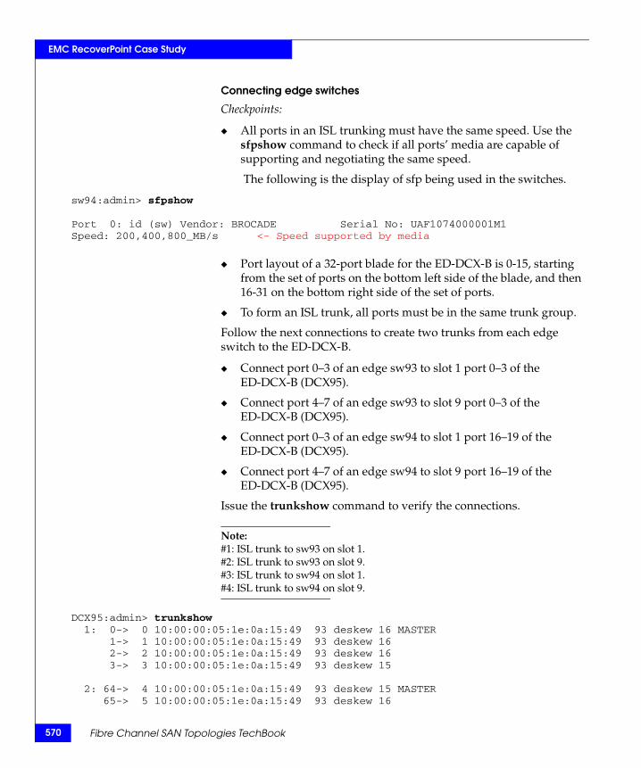
570
EMC RecoverPoint Case Study
Connecting edge switches
Checkpoints:
◆ All ports in an ISL trunking must have the same speed. Use the sfpshow command to check if all ports’ media are capable of supporting and negotiating the same speed.
The following is the display of sfp being used in the switches.
sw94:admin> sfpshow
Port 0: id (sw) Vendor: BROCADE Serial No: UAF1074000001M1 Speed: 200,400,800_MB/s <- Speed supported by media
◆ Port layout of a 32-port blade for the ED-DCX-B is 0-15, starting from the set of ports on the bottom left side of the blade, and then 16-31 on the bottom right side of the set of ports.
◆ To form an ISL trunk, all ports must be in the same trunk group.
Follow the next connections to create two trunks from each edge switch to the ED-DCX-B.
◆ Connect port 0–3 of an edge sw93 to slot 1 port 0–3 of the ED-DCX-B (DCX95).
◆ Connect port 4–7 of an edge sw93 to slot 9 port 0–3 of the ED-DCX-B (DCX95).
◆ Connect port 0–3 of an edge sw94 to slot 1 port 16–19 of the ED-DCX-B (DCX95).
◆ Connect port 4–7 of an edge sw94 to slot 9 port 16–19 of the ED-DCX-B (DCX95).
Issue the trunkshow command to verify the connections.
Note: #1: ISL trunk to sw93 on slot 1.#2: ISL trunk to sw93 on slot 9.#3: ISL trunk to sw94 on slot 1.#4: ISL trunk to sw94 on slot 9.
DCX95:admin> trunkshow 1: 0-> 0 10:00:00:05:1e:0a:15:49 93 deskew 16 MASTER 1-> 1 10:00:00:05:1e:0a:15:49 93 deskew 16 2-> 2 10:00:00:05:1e:0a:15:49 93 deskew 16 3-> 3 10:00:00:05:1e:0a:15:49 93 deskew 15
2: 64-> 4 10:00:00:05:1e:0a:15:49 93 deskew 15 MASTER 65-> 5 10:00:00:05:1e:0a:15:49 93 deskew 16
Fibre Channel SAN Topologies TechBook
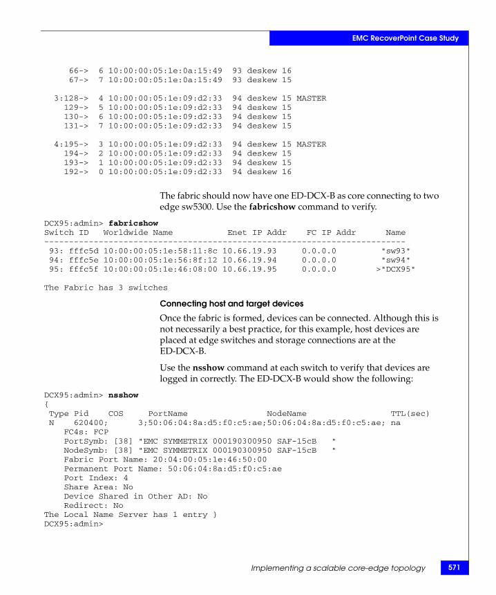
EMC RecoverPoint Case Study
66-> 6 10:00:00:05:1e:0a:15:49 93 deskew 16 67-> 7 10:00:00:05:1e:0a:15:49 93 deskew 15
3:128-> 4 10:00:00:05:1e:09:d2:33 94 deskew 15 MASTER 129-> 5 10:00:00:05:1e:09:d2:33 94 deskew 15 130-> 6 10:00:00:05:1e:09:d2:33 94 deskew 15 131-> 7 10:00:00:05:1e:09:d2:33 94 deskew 15
4:195-> 3 10:00:00:05:1e:09:d2:33 94 deskew 15 MASTER 194-> 2 10:00:00:05:1e:09:d2:33 94 deskew 15 193-> 1 10:00:00:05:1e:09:d2:33 94 deskew 15 192-> 0 10:00:00:05:1e:09:d2:33 94 deskew 16
The fabric should now have one ED-DCX-B as core connecting to two edge sw5300. Use the fabricshow command to verify.
DCX95:admin> fabricshowSwitch ID Worldwide Name Enet IP Addr FC IP Addr Name------------------------------------------------------------------------- 93: fffc5d 10:00:00:05:1e:58:11:8c 10.66.19.93 0.0.0.0 "sw93" 94: fffc5e 10:00:00:05:1e:56:8f:12 10.66.19.94 0.0.0.0 "sw94" 95: fffc5f 10:00:00:05:1e:46:08:00 10.66.19.95 0.0.0.0 >"DCX95"
The Fabric has 3 switches
Connecting host and target devices
Once the fabric is formed, devices can be connected. Although this is not necessarily a best practice, for this example, host devices are placed at edge switches and storage connections are at the ED-DCX-B.
Use the nsshow command at each switch to verify that devices are logged in correctly. The ED-DCX-B would show the following:
DCX95:admin> nsshow{ Type Pid COS PortName NodeName TTL(sec) N 620400; 3;50:06:04:8a:d5:f0:c5:ae;50:06:04:8a:d5:f0:c5:ae; na FC4s: FCP PortSymb: [38] "EMC SYMMETRIX 000190300950 SAF-15cB " NodeSymb: [38] "EMC SYMMETRIX 000190300950 SAF-15cB " Fabric Port Name: 20:04:00:05:1e:46:50:00 Permanent Port Name: 50:06:04:8a:d5:f0:c5:ae Port Index: 4 Share Area: No Device Shared in Other AD: No Redirect: NoThe Local Name Server has 1 entry }DCX95:admin>
Implementing a scalable core-edge topology 571
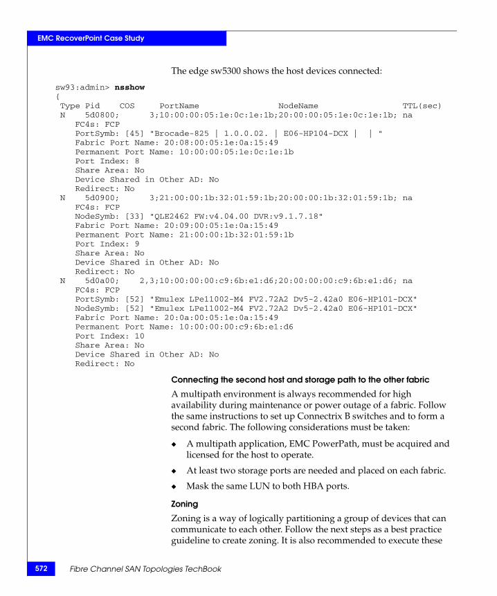
572
EMC RecoverPoint Case Study
The edge sw5300 shows the host devices connected:
sw93:admin> nsshow{ Type Pid COS PortName NodeName TTL(sec) N 5d0800; 3;10:00:00:05:1e:0c:1e:1b;20:00:00:05:1e:0c:1e:1b; na FC4s: FCP PortSymb: [45] "Brocade-825 | 1.0.0.02. | E06-HP104-DCX | | " Fabric Port Name: 20:08:00:05:1e:0a:15:49 Permanent Port Name: 10:00:00:05:1e:0c:1e:1b Port Index: 8 Share Area: No Device Shared in Other AD: No Redirect: No N 5d0900; 3;21:00:00:1b:32:01:59:1b;20:00:00:1b:32:01:59:1b; na FC4s: FCP NodeSymb: [33] "QLE2462 FW:v4.04.00 DVR:v9.1.7.18" Fabric Port Name: 20:09:00:05:1e:0a:15:49 Permanent Port Name: 21:00:00:1b:32:01:59:1b Port Index: 9 Share Area: No Device Shared in Other AD: No Redirect: No N 5d0a00; 2,3;10:00:00:00:c9:6b:e1:d6;20:00:00:00:c9:6b:e1:d6; na FC4s: FCP PortSymb: [52] "Emulex LPe11002-M4 FV2.72A2 Dv5-2.42a0 E06-HP101-DCX" NodeSymb: [52] "Emulex LPe11002-M4 FV2.72A2 Dv5-2.42a0 E06-HP101-DCX" Fabric Port Name: 20:0a:00:05:1e:0a:15:49 Permanent Port Name: 10:00:00:00:c9:6b:e1:d6 Port Index: 10 Share Area: No Device Shared in Other AD: No Redirect: No
Connecting the second host and storage path to the other fabric
A multipath environment is always recommended for high availability during maintenance or power outage of a fabric. Follow the same instructions to set up Connectrix B switches and to form a second fabric. The following considerations must be taken:
◆ A multipath application, EMC PowerPath, must be acquired and licensed for the host to operate.
◆ At least two storage ports are needed and placed on each fabric.
◆ Mask the same LUN to both HBA ports.
Zoning
Zoning is a way of logically partitioning a group of devices that can communicate to each other. Follow the next steps as a best practice guideline to create zoning. It is also recommended to execute these
Fibre Channel SAN Topologies TechBook
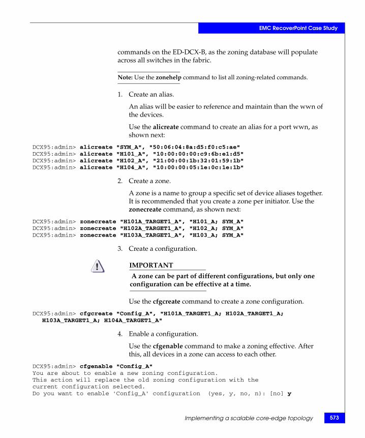
EMC RecoverPoint Case Study
commands on the ED-DCX-B, as the zoning database will populate across all switches in the fabric.
Note: Use the zonehelp command to list all zoning-related commands.
1. Create an alias.
An alias will be easier to reference and maintain than the wwn of the devices.
Use the alicreate command to create an alias for a port wwn, as shown next:
DCX95:admin> alicreate "SYM_A", "50:06:04:8a:d5:f0:c5:ae"DCX95:admin> alicreate "H101_A", "10:00:00:00:c9:6b:e1:d5"DCX95:admin> alicreate "H102_A", "21:00:00:1b:32:01:59:1b"DCX95:admin> alicreate "H104_A", "10:00:00:05:1e:0c:1e:1b"
2. Create a zone.
A zone is a name to group a specific set of device aliases together. It is recommended that you create a zone per initiator. Use the zonecreate command, as shown next:
DCX95:admin> zonecreate "H101A_TARGET1_A", "H101_A; SYM_A"DCX95:admin> zonecreate "H102A_TARGET1_A", "H102_A; SYM_A"DCX95:admin> zonecreate "H103A_TARGET1_A", "H103_A; SYM_A"
3. Create a configuration.
IMPORTANT! A zone can be part of different configurations, but only one configuration can be effective at a time.
Use the cfgcreate command to create a zone configuration.
DCX95:admin> cfgcreate "Config_A", "H101A_TARGET1_A; H102A_TARGET1_A; H103A_TARGET1_A; H104A_TARGET1_A"
4. Enable a configuration.
Use the cfgenable command to make a zoning effective. After this, all devices in a zone can access to each other.
DCX95:admin> cfgenable "Config_A"You are about to enable a new zoning configuration.This action will replace the old zoning configuration with thecurrent configuration selected.Do you want to enable 'Config_A' configuration (yes, y, no, n): [no] y
Implementing a scalable core-edge topology 573
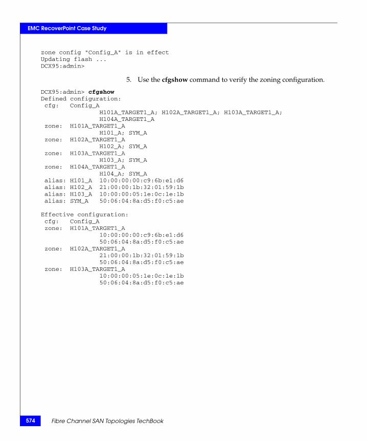
574
EMC RecoverPoint Case Study
zone config "Config_A" is in effectUpdating flash ...DCX95:admin>
5. Use the cfgshow command to verify the zoning configuration.
DCX95:admin> cfgshowDefined configuration: cfg: Config_A H101A_TARGET1_A; H102A_TARGET1_A; H103A_TARGET1_A; H104A_TARGET1_A zone: H101A_TARGET1_A H101_A; SYM_A zone: H102A_TARGET1_A H102_A; SYM_A zone: H103A_TARGET1_A H103_A; SYM_A zone: H104A_TARGET1_A H104_A; SYM_A alias: H101_A 10:00:00:00:c9:6b:e1:d6 alias: H102_A 21:00:00:1b:32:01:59:1balias: H103_A 10:00:00:05:1e:0c:1e:1balias: SYM_A 50:06:04:8a:d5:f0:c5:ae
Effective configuration: cfg: Config_A zone: H101A_TARGET1_A 10:00:00:00:c9:6b:e1:d6 50:06:04:8a:d5:f0:c5:ae zone: H102A_TARGET1_A 21:00:00:1b:32:01:59:1b 50:06:04:8a:d5:f0:c5:aezone: H103A_TARGET1_A
10:00:00:05:1e:0c:1e:1b 50:06:04:8a:d5:f0:c5:ae
Fibre Channel SAN Topologies TechBook
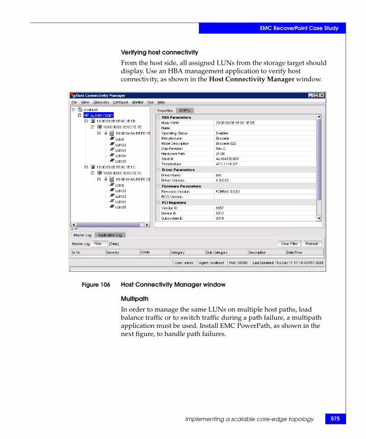
EMC RecoverPoint Case Study
Verifying host connectivity
From the host side, all assigned LUNs from the storage target should display. Use an HBA management application to verify host connectivity, as shown in the Host Connectivity Manager window.
Figure 106 Host Connectivity Manager window
Multipath
In order to manage the same LUNs on multiple host paths, load balance traffic or to switch traffic during a path failure, a multipath application must be used. Install EMC PowerPath, as shown in the next figure, to handle path failures.
Implementing a scalable core-edge topology 575
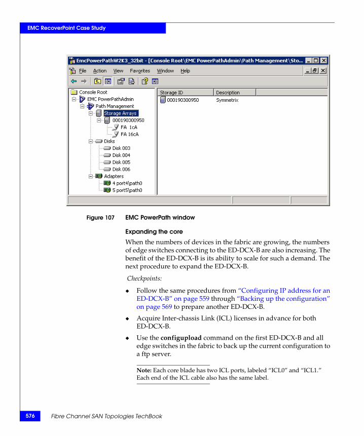
576
EMC RecoverPoint Case Study
Figure 107 EMC PowerPath window
Expanding the core
When the numbers of devices in the fabric are growing, the numbers of edge switches connecting to the ED-DCX-B are also increasing. The benefit of the ED-DCX-B is its ability to scale for such a demand. The next procedure to expand the ED-DCX-B.
Checkpoints:
◆ Follow the same procedures from “Configuring IP address for an ED-DCX-B” on page 559 through “Backing up the configuration” on page 569 to prepare another ED-DCX-B.
◆ Acquire Inter-chassis Link (ICL) licenses in advance for both ED-DCX-B.
◆ Use the configupload command on the first ED-DCX-B and all edge switches in the fabric to back up the current configuration to a ftp server.
Note: Each core blade has two ICL ports, labeled “ICL0” and “ICL1.” Each end of the ICL cable also has the same label.
Fibre Channel SAN Topologies TechBook
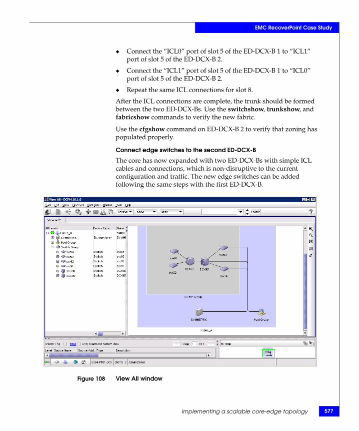
EMC RecoverPoint Case Study
◆ Connect the “ICL0” port of slot 5 of the ED-DCX-B 1 to “ICL1” port of slot 5 of the ED-DCX-B 2.
◆ Connect the “ICL1” port of slot 5 of the ED-DCX-B 1 to “ICL0” port of slot 5 of the ED-DCX-B 2.
◆ Repeat the same ICL connections for slot 8.
After the ICL connections are complete, the trunk should be formed between the two ED-DCX-Bs. Use the switchshow, trunkshow, and fabricshow commands to verify the new fabric.
Use the cfgshow command on ED-DCX-B 2 to verify that zoning has populated properly.
Connect edge switches to the second ED-DCX-B
The core has now expanded with two ED-DCX-Bs with simple ICL cables and connections, which is non-disruptive to the current configuration and traffic. The new edge switches can be added following the same steps with the first ED-DCX-B.
Figure 108 View All window
Implementing a scalable core-edge topology 577

578
EMC RecoverPoint Case Study
Fibre Channel SAN Topologies TechBook
7Invisible Body Tag
This chapter provides the following information on FICON topologies.
◆ Overview........................................................................................... 580◆ Topology support............................................................................. 582◆ Zoning practices ............................................................................... 583◆ Cascading .......................................................................................... 584◆ Terminology...................................................................................... 585◆ IOCP considerations ........................................................................ 587◆ FICON and EMC Ionix ControlCenter ......................................... 589◆ CUP (fabric management server) .................................................. 590◆ Connectrix B series........................................................................... 591◆ Connectrix M series ......................................................................... 594◆ Connectrix MDS series .................................................................... 600
FICON Topologies
FICON Topologies 579
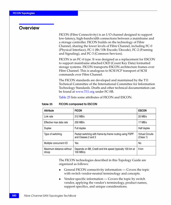
580
FICON Topologies
OverviewFICON (Fibre Connectivity) is an I/O channel designed to support low-latency, high-bandwidth connections between a mainframe and a storage controller. FICON builds on the technology of Fibre Channel, sharing the lower levels of Fibre Channel, including FC-0 (Physical Interface), FC-1 (8b/10b Encode/Decode), FC-2 (Framing and Signaling), and FC-3 (Common Services).
FICON is an FC-4 type. It was designed as a replacement for ESCON to support mainframe attached CKD (Count Key Data) formatted storage systems. FICON transports ESCON architecture frames over Fibre Channel. This is analogous to SCSI FCP transport of SCSI commands over Fibre Channel.
The FICON standards are developed and maintained by the T11 Technical Committee of the International Committee for Information Technology Standards. Drafts and other technical documentation can be found at www.T11.org under FC-SB.
Table 25 lists some attributes of FICON and ESCON.
The FICON technologies described in this Topology Guide are organized as follows:
◆ General FICON connectivity information — Covers the topic with switch vendor-neutral terminology and concepts.
◆ Vendor-specific information — Covers the topic by switch vendor, applying the vendor's terminology, product names, support specifics, and unique considerations.
Table 25 FICON compared to ESCON
Attribute FICON ESCON
Link rate 212 MB/s 20 MB/s
Effective max data rate 200 MB/s 17 MB/s
Duplex Full duplex Half duplex
Type of switching Packet switching with frame-by-frame routing using FSPF and Classes 2 and 3
Virtual Circuits (Class 1)
Multiple concurrent I/O Yes No
Maximum distance without droop
Depends on BB_Credit and link speed (typically 100 km at 100 MB/s).
9 km
Fibre Channel SAN Topologies TechBook

FICON Topologies
Refer to:
• “Connectrix B series” on page 591• “Connectrix M series” on page 594• “Connectrix MDS series” on page 600
Reference material Refer to the following for more information:
◆ Connectrix documentation on Powerlink
◆ HCD/IOCP: http://www.ibm.com/servers/resourcelinkSelect Library, then the appropriate Mainframe CPU
◆ IBM Redbooks, at http://www.ibm.com/redbooks:• FICON Native Implementation and Reference Guide, PN
SG24-6266-01• Getting Started with the Brocade M Series Intrepid FICON
Director, PN SG24-6857-00• Getting Started with the Inrange FC/9000 FICON Director,
PN SG24-6858-00
• Cisco FICON Basic Implementation, PN REDP-4392-00
Overview 581
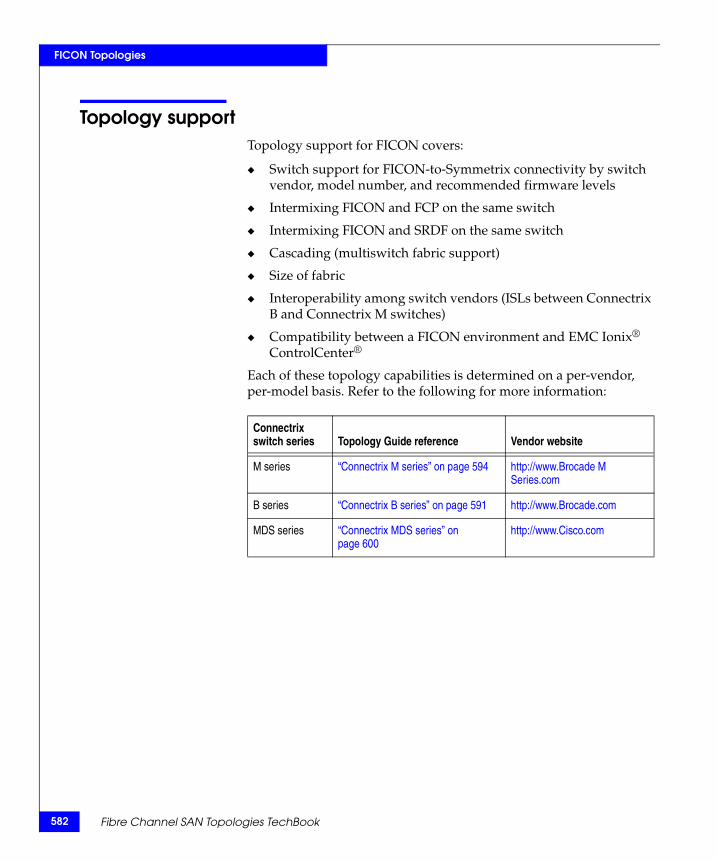
582
FICON Topologies
Topology supportTopology support for FICON covers:
◆ Switch support for FICON-to-Symmetrix connectivity by switch vendor, model number, and recommended firmware levels
◆ Intermixing FICON and FCP on the same switch
◆ Intermixing FICON and SRDF on the same switch
◆ Cascading (multiswitch fabric support)
◆ Size of fabric
◆ Interoperability among switch vendors (ISLs between Connectrix B and Connectrix M switches)
◆ Compatibility between a FICON environment and EMC Ionix® ControlCenter®
Each of these topology capabilities is determined on a per-vendor, per-model basis. Refer to the following for more information:
Connectrix switch series Topology Guide reference Vendor website
M series “Connectrix M series” on page 594 http://www.Brocade M Series.com
B series “Connectrix B series” on page 591 http://www.Brocade.com
MDS series “Connectrix MDS series” on page 600
http://www.Cisco.com
Fibre Channel SAN Topologies TechBook
FICON Topologies
Zoning practicesThe recommended zoning practice for FICON environments is to build a single FICON zone and include all FICON N_Ports, channels, and control units in that zone. FICON channels depend on State Change Notifications (SCNs) from the switch to perform error recovery.
A single zone is administratively simple, and insures that all FICON N_Ports receive their SCNs. Zoning based on World Wide Port Name (WWPN) is recommended, but port-based zoning is also supported. This practice varies from the Single Initiator zoning of Open Systems, because mainframe channels do not depend on the name server for device discovery. Instead, mainframes use the device address information in the IOCDS for discovery. (“IOCP considerations” on page 587 provides more information.)
If the switch or fabric includes Open Systems (intermix) or SRDF ports, these ports should be zoned per practices. For Open Systems, this is single-initiator zoning based on WWPN. For SRDF, place all SRDF ports into a single SRDF zone.
Note: Refer to “Use single initiator zoning” on page 24 for information on SRDF zoning.
Zoning practices 583
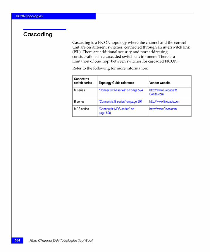
584
FICON Topologies
CascadingCascading is a FICON topology where the channel and the control unit are on different switches, connected through an interswitch link (ISL). There are additional security and port addressing considerations in a cascaded switch environment. There is a limitation of one 'hop' between switches for cascaded FICON.
Refer to the following for more information:
Connectrix switch series Topology Guide reference Vendor website
M series “Connectrix M series” on page 594 http://www.Brocade M Series.com
B series “Connectrix B series” on page 591 http://www.Brocade.com
MDS series “Connectrix MDS series” on page 600
http://www.Cisco.com
Fibre Channel SAN Topologies TechBook
FICON Topologies
Terminology◆ Entry switch — A FICON switch that is connected to the
processor's FICON channel(s) and to a cascaded switch. An entry switch can also be a cascaded switch.
◆ Cascaded switch — A FICON director that connects to a control unit (, for example, a storage array) and to an entry switch. A cascaded switch can also be an entry switch.
◆ Switch ID and switch address (1 byte) — Ways to address a FICON director. The Switch ID and Switch address describe fields used in the IOCDS. Both values should be set equal to the Domain ID of the switch.
The IOCDS expects physical values in hex. In this context, the physical value refers to the value that would be seen in a Finisar/I-Tech trace. The logical value would be the value as seen from a management application. Since the switch vendors may use logical values (a physical value plus an offset) and display the Domain ID in decimal, care must be taken when transferring this information from the switch's management application to the IOCDS. Refer the specific switch vendor information:
• “Connectrix B series” on page 591
• “Connectrix M series” on page 594
• “Connectrix MDS series” on page 600
The switch ID is assigned by the customer, and must be unique within the scope of the IOCP (Input/Output Configuration Program) or HCD (Hardware Configuration Definition). The switch ID is an arbitrary unique number given to identify the switch. It is highly recommended that the switch ID be set equal to the Domain ID.
The link statement in the IOCDS is where the actual switch Domain ID and port address are defined. For example, the link statement LINK= (6104,6104) defines a connection to port 4 on Domain ID 1.
The switch address is the Domain ID of the switch. These addresses can be customized to a preplanned value. They must be unique within a fabric.
◆ Port address — Address (with a one-byte value) of the physical FICON director port.
Terminology 585
586
FICON Topologies
◆ Insistent Domain ID — A switch using the Insistent Domain ID feature ensures that it will join a fabric if (and only if) its administratively assigned Domain ID is granted during the fabric initialization procedure.
Notes on cascading
Switch addresses for FICON directors must be unique across all of the processor's CHPIDs (Channel Path Identifiers).
With SYSPLEX installations, the switch address must be unique across the SYSPLEX complex.
Cascading requires the use of two-byte link addresses that consist of a high-order byte defining the switch address (Domain ID) and a low-order byte that defines the FICON director port address.
Two-byte link addresses require that the FICON director have the Fabric Binding and Insistent Domain ID features installed. The channel checks this during initialization by sending the Security Attributes Extended Link Services query to the switch. In the response from the switch, the channel checks that Fabric Binding Enforcement and Insistent Domain ID bits are set. If they are not set, the link does not complete initialization.
Fibre Channel SAN Topologies TechBook
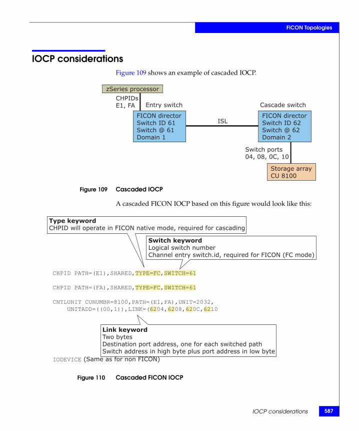
FICON Topologies
IOCP considerationsFigure 109 shows an example of cascaded IOCP.
Figure 109 Cascaded IOCP
A cascaded FICON IOCP based on this figure would look like this:
Figure 110 Cascaded FICON IOCP
ISL
Entry switch Cascade switch
Switch ports04, 08, 0C, 10
CHPIDsE1, FA
zSeries processor
FICON directorSwitch ID 61Switch @ 61Domain 1
Storage arrayCU 8100
FICON directorSwitch ID 62Switch @ 62Domain 2
CHPID PATH=(E1),SHARED,TYPE=FC,SWITCH=61
CHPID PATH=(FA),SHARED,TYPE=FC,SWITCH=61
CNTLUNIT CUNUMBR=8100,PATH=(E1,FA),UNIT=2032, UNITADD=((00,1)),LINK=(6204,6208,620C,6210
IODEVICE (Same as for non FICON)
Type keywordCHPID will operate in FICON native mode, required for cascading
Switch keywordLogical switch numberChannel entry switch.id, required for FICON (FC mode)
Link keywordTwo bytesDestination port address, one for each switched pathSwitch address in high byte plus port address in low byte
IOCP considerations 587
588
FICON Topologies
Once a two-byte link address has been specified for a channel path:
◆ It is recommended that you specify two-byte link addresses for all paths from the same CEC that have the same entry switch.
• This allows IOCP to perform better checking of the switch configuration.
• HCD requires additional information and performs a different checking method; therefore, the above is an IOCP recommendation only.
◆ All link addresses defined for access from the same channel path must be two-byte link addresses.
Fibre Channel SAN Topologies TechBook
FICON Topologies
FICON and EMC Ionix ControlCenterThe EMC Ionix ControlCenter switch management functions (including zoning) are qualified on a switch vendor basis. Refer to the specific switch vendor information for the latest support.
Any time there is more than one management control point, care must be taken to insure that administrative conflicts do not arise. With ControlCenter there can be three separate and potentially conflicting control points: ControlCenter, Connectrix Manager, and System Automation OS/390. It is largely the administrator's responsibility to insure that conflicting controls are avoided.
As a result, having a single administrator in an intermix environment for all Open Systems and FICON switch management is the preferred practice.
FICON and EMC Ionix ControlCenter 589

590
FICON Topologies
CUP (fabric management server)Control Unit Port (CUP) is an inband communications protocol that allows an OS/390 to manage a switch with the same level of control and security that S/390 has on an ESCON switch. Control functions include blocking and unblocking ports, as well as error reporting and monitoring.
CUP is also required for other mainframe management functions, such as:
◆ HCD — Port activation/deactivation
◆ HCM — Performance display
◆ SMF — Performance statistics gathering for RMF
◆ ZOS — Error handling, problem determination
◆ DCM — Dynamic CHPID management
The services provided by CUP are used by IBM management software System Automation for OS/390. In the case of the Connectrix M series product line, this management system depends on storage services provided by the Connectrix service processor for maintaining CUP-controlled configuration files.
CUP is not a requirement for mainframe/storage FICON connectivity. Typically, large mainframe data centers utilize its services.
Fibre Channel SAN Topologies TechBook
FICON Topologies
Connectrix B seriesThis section contains the following information:
◆ “Supported products” on page 591
◆ “Configuring” on page 591
◆ “OCP considerations” on page 592
◆ “CUP support” on page 592
◆ “Switch node identifier” on page 593
◆ “EMC documentation” on page 593
Supported productsThese B series products support FICON connectivity:
◆ DS-32B2
◆ DS-4100B
◆ ED-12000B
◆ ED-24000B
◆ ED-48000B
◆ DS-4900B
◆ PB-48K-18i blade (FC-IP)
◆ Silkworm 7500 (FC-IP)
Configuring
Topology support
◆ Single switch is supported.
◆ Cascading is supported with FOS 5.2.1 or higher
• Cascading is not supported with ED-12000B.
◆ Intermixing FICON and FCP on the same switch is supported.
In a FCP/FICON intermix environment, as long as the FICON N_Ports, Channel, and Control Unit reside on the same domain, and the IOCDS uses single byte addressing, FICON I/O in a cascaded Open Systems Brocade fabric is supported.
Connectrix B series 591
592
FICON Topologies
◆ Intermixing FICON and SRDF on the same switch is supported.
◆ B series/M series interoperability is not supported in a FICON environment.
Recommended FICON environment configuration settings
◆ The older FICON products may not connect to 8 Gb ports. The 8 Gb SFP negotiates only to 2, 4 or 8 Gb link speeds.
• Older FICON products may only support a 1 Gb link speed.
• A switch port with a 4 Gb SFP will be required for connectivity. The 4 Gb SFP negotiates to 1, 2, or 4 Gb link speeds.
◆ The fillword needs to be set to ARB(FF) for 8 Gb to 8 Gb connections. The IDLE fillword is still used for slower link speeds.
◆ Enable in-order delivery (iodset command).
OCP considerationsSwitch ID Definition — No offsets on switch ID or port address, but every value must be in hex for the mainframe.
CUP supportCUP is a separately licensed inband management service installed on each switch.
You can manage CUP using Web Tools or Fabric Manager. Limited support for CUP is provided through the Fabric OS CLI.
CUP provides the following advantages:
◆ Single point of control and monitoring for channel, director (switch), and control unit.
◆ Automated tools on the mainframe can take advantage of the statistics to move channels where they are needed. This cannot be done from the switch alone.
◆ Seamless integration into existing management tools that are also used to manage ESCON directors (switches). This makes migration from ESCON to FICON smoother.
Fibre Channel SAN Topologies TechBook
FICON Topologies
You can monitor the FICON director (switch) using CUP to obtain the following port statistics:
◆ Number of words transmitted
◆ Number of words received
◆ Frame Pacing Time (the number of 2.5 ms units that frame transmission is blocked due to zero credit).
Refer to the IBM document FICON Director Programming Interface with Cascading Support.
Switch node identifier
You can find switch node information such as the serial number and manufacturer name. This information is the same as the Switch Node ID in the RNID ELS:
◆ Configuration file information — Provides a list of configuration files on the switch. You can also obtain the actual file content, including port address name and port connectivity.
◆ History summary (director history buffer) — The history buffer logs each change in status or configuration of the ports. You can retrieve the history buffer using CUP.
◆ Switch configuration data — Provides switch configuration data such as time-out values and number of ports per card.
You can find information on CUP functions and commands in the IBM-proprietary document FICON Director Programming Interface With Cascading Support.
EMC documentationRefer to these documents for more information on FICON connectivity:
◆ EMC Connectrix B Series Version 4.4 Features Guide (P/N 300-001-702)
◆ EMC Connectrix B Series Fabric OS Version 4.4 Procedures Guide (P/N 300-001-708)
Connectrix B series 593
594
FICON Topologies
Connectrix M seriesThis section contains the following information:
◆ “Supported products” on page 594
◆ “Configuring” on page 594
◆ “IOCP configuration” on page 595
◆ “Distance options” on page 597
◆ “SANtegrity” on page 598
◆ “Address swapping” on page 598
◆ “CUP” on page 599
Supported products
Supported M series products are:
◆ ED-10000M
◆ ED-140M
◆ ED-64M
◆ ED-1032
◆ DS-32M2
◆ DS-4700M
These products are further described in the EMC Connectrix SAN Products Data Reference Manual, available through the E-Lab Interoperability Navigator, Topology Resource Center tab, at http://elabnavigator.EMC.com.
Configuring
Topology support
Note the following:
◆ Intermixing FICON and FCP on a Brocade M series fabric is supported. It is recommended that all E/OS-based products use firmware version 6.01 or higher to take advantage of improvements in availability.
◆ Intermixing FICON and SRDF on the same fabric is supported.
Fibre Channel SAN Topologies TechBook
FICON Topologies
◆ FICON is supported in homogeneous fabrics; all switches in the fabric must be from the same switch vendor.
◆ The EMC Ionix ControlCenter switch management functions (including zoning) can be used to manage a switch in a FICON or FICON/FCP intermix environment. ControlCenter 5.1.2 or higher is required.
Note: Any time there is more than one management control point, care must be taken to insure that administrative conflicts do not arise. With EMC Ionix ControlCenter, there may be three separate and potentially conflicting control points: ControlCenter, Connectrix Manager, and System Automation OS/390. It is largely the administrator's responsibility to insure that conflicting controls are avoided. As a result, having a single administrator in an intermix environment for all Open Systems and FICON switch management is the preferred practice.
IOCP configuration
Note the following:
◆ Brocade M series switch ID definition — The switch ID is the Domain ID plus x’60’.
Example: Domain ID 1 would be switch ID x’61’.
◆ Brocade M series port address:
• On the ED-10000M and DS-4700M, the physical port mapping maps directly to the logical port mapping.
• On any other supported M series switch, the logical port address is the physical port address plus 4 in hex (if there has been no port swapping). For these switches, you must use the logical port address, not the physical port address.
The physical port address refers to the address associated with the physical position of the port card in the chassis, and the specific port on the port card.
The logical port address can be swapped using the Swap Ports function on the Element Manager's Maintenance pull-down menu. By using the FICON setting in the Management Style option in the Element Manager's Product pull-down menu, the translation from physical (Port #) to logical (Addr) can be determined. Use the Addr value found in the Port List tab in the IOCDS.
Connectrix M series 595
596
FICON Topologies
Example: Physical port 6 would be logical port x’A’, assuming there has been no port swapping.
Connectrix Manager: Fabric Manager
Note the following:
◆ Zoning — Refer to “Zoning practices” on page 583.
Prior to the support of intermix, the State Change Notification distribution in a Connectrix M series FICON environment was accomplished by enabling default zoning and having no active zone set. This practice is supported in FICON-only environments, but is no longer recommended.
◆ Default zoning — The recommended setting disabled. When new N_Ports are added to the fabric, disabling the default zone prevents these new N_Ports from becoming aware of other N_Ports. This function is controlled in the Zoning dialog box of the Connectrix Manager Fabric Manager.
◆ Enterprise Fabric Mode — Must be enabled in order to support cascading. In order to enable this mode, every switch in the fabric must have the SANtegrity feature enabled (using the Connectrix Fabric Manager Configure menu).
Enabling this mode automatically enables the following parameters. These parameters cannot be disabled unless the switch is offline. Disabling any of these parameters also disables Enterprise Fabric Mode.
• Rerouting Delay
• Domain RSCNs (Register for State Change Notifications)
• Insistent Domain ID
Switch Element Manager-level FICON configuration considerations
Note the following:
◆ Open Fabric Mode — This is the recommended interoperability mode for both FICON-only and FICON/FCP intermix fabrics.
◆ Suppress Zoning RSCNs on Zone Set Activations — FICON Channels do not use Fabric Format RSCNs. Therefore, this setting may be enabled or disabled.
Fibre Channel SAN Topologies TechBook
FICON Topologies
This option has been superseded in E/OS 7.01 and above. E/OS 7.01 has an RSCN filtering function, sometimes called Zone Flexpars. Refer to the EMC Connectrix E/OS 7.01 Release Notes for details.
◆ Preferred Pathing and PDCM on E_Ports — These are new switch features offered in Connectrix M series firmware 6.01 that offer route control for segregating FICON and FCP traffic over ISLs on a per-N_Port basis. In order to use the PDCM controls, the Element Manager Management Style must be set for FICON.
◆ Unified Management Mode — In E/OS 06.xx.xx and higher, the separate OS/390 and Open Systems modes of operation for FICON and Open Systems networks have been consolidated.
In Connectrix Manager, this feature changes the function of the FICON Management Style (previously OS/390 operating mode) and Open Systems Management Style (previously Open Systems operating mode) options. These options are available through the Management Style option on the Product menu.
If E/OS 06.xx.xx or higher is installed on the switch and you are using Connectrix Manager 08.xx.xx, you do not have to set the switch to the offline state before changing the Management Style. Previously you had to take the product offline before changing management styles or operating modes.
You can now switch to Open Systems Management style even if the optional FICON Management Server feature is installed. Previously, you could only use FICON Management Style if this feature was installed.
You can now enable the Open Systems Management Server (OSMS) and FICON Management Server features simultaneously. Previously, you could enable only one type of management server feature at a time for a switch.
Distance optionsDistance options are:
◆ DSED-LWKT20 — Single-mode longwave optic, 20 km distance
◆ DSED-LWKT35 — Single-mode longwave optic, 35 km distance
Connectrix M series 597
598
FICON Topologies
SANtegritySANtegrity provides a layer of security to network ports, switches, and fabrics through authorization, authentication, and secure management techniques in Open Systems or mainframe environments. SANtegrity ensures that Fibre Channel traffic is not redirected by unauthorized access.
In mainframe FICON environments, SANtegrity enables FICON cascading because it provides a layer of security to the fabric required by the channel. SANtegrity is separately licensed and is a requirement on every switch in a fabric to enable Enterprise Fabric Mode (high integrity mode).
The following are SANtegrity features:
◆ Fabric Binding — Prevents unauthorized switches from joining a fabric.
◆ Switch Binding — Allows users to restrict connections to an individual switch, for either E_Port connections, F_Port connections, or all connections. Switch Binding can be enabled without enabling Enterprise Fabric Mode.
◆ Insistent Domain ID — Prohibits the use of dynamic Domain IDs to ensure that predictable Domain IDs are being enforced within the fabric. This is important for Fabric Binding because changing the Domain ID on a switch can cause segmentation resulting from the exclusion of a switch from the fabric.
Insistent Domain IDs are critical to FICON addressing, and are set automatically set when Enterprise Fabric mode or Fabric Binding is enabled.
◆ Rerouting Delay — Ensures that frames are delivered through the fabric in order to reach their destination.
◆ Domain RSCNs — Allows the switch to transmit Domain RSCNs between end devices in a fabric to provide additional connection information to host bus adapters and storage devices.
Address swappingThe logical address of a physical port is specified in the HCD on the mainframe. Typically the HCD must be changed when moving a FICON link between switch ports. However, a Port address Swapping feature in the Connectrix Manager Element Manager can
Fibre Channel SAN Topologies TechBook
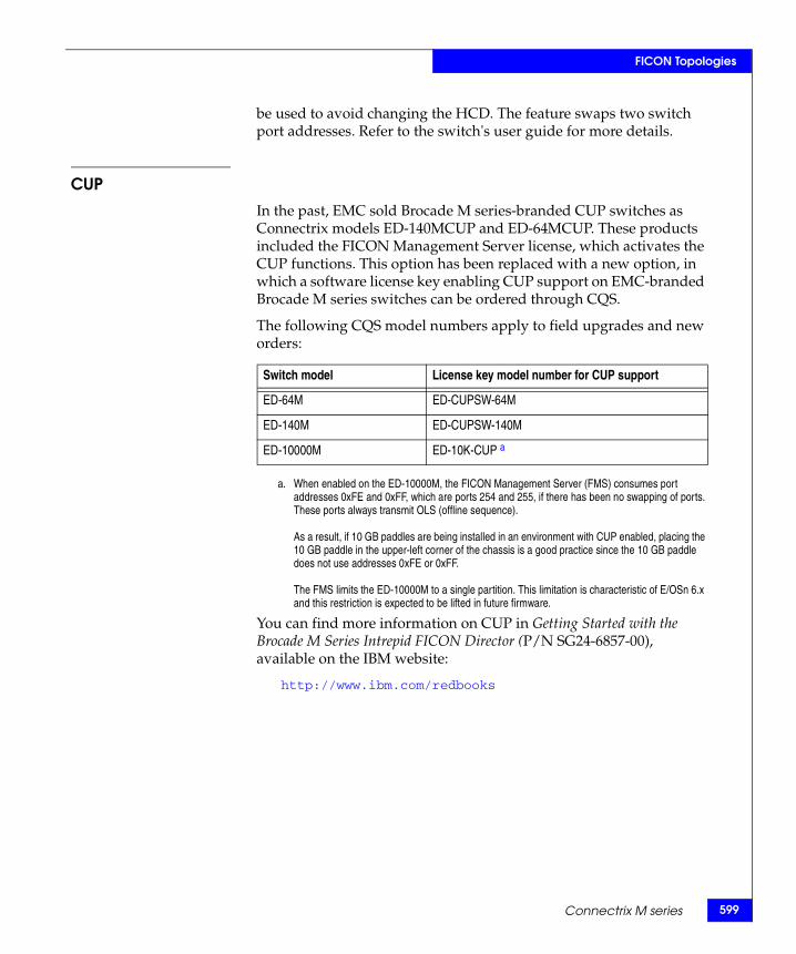
FICON Topologies
be used to avoid changing the HCD. The feature swaps two switch port addresses. Refer to the switch's user guide for more details.
CUP
In the past, EMC sold Brocade M series-branded CUP switches as Connectrix models ED-140MCUP and ED-64MCUP. These products included the FICON Management Server license, which activates the CUP functions. This option has been replaced with a new option, in which a software license key enabling CUP support on EMC-branded Brocade M series switches can be ordered through CQS.
The following CQS model numbers apply to field upgrades and new orders:
a. When enabled on the ED-10000M, the FICON Management Server (FMS) consumes port addresses 0xFE and 0xFF, which are ports 254 and 255, if there has been no swapping of ports. These ports always transmit OLS (offline sequence).
As a result, if 10 GB paddles are being installed in an environment with CUP enabled, placing the 10 GB paddle in the upper-left corner of the chassis is a good practice since the 10 GB paddle does not use addresses 0xFE or 0xFF.
The FMS limits the ED-10000M to a single partition. This limitation is characteristic of E/OSn 6.x and this restriction is expected to be lifted in future firmware.
You can find more information on CUP in Getting Started with the Brocade M Series Intrepid FICON Director (P/N SG24-6857-00), available on the IBM website:
http://www.ibm.com/redbooks
Switch model License key model number for CUP support
ED-64M ED-CUPSW-64M
ED-140M ED-CUPSW-140M
ED-10000M ED-10K-CUP a
Connectrix M series 599
600
FICON Topologies
Connectrix MDS seriesThis section contains the following information:
◆ “Supported products” on page 600
◆ “Requirements” on page 600
◆ “Configuring” on page 601
◆ “OCP considerations” on page 602
◆ “CUP support” on page 602
◆ “FICON configuration files” on page 602
◆ “Switch node identifier” on page 603
◆ “FICON port numbering” on page 604
◆ “References” on page 605
Supported productsThese MDS series products support FICON connectivity:
◆ MDS 9513
◆ MDS 9509
◆ MDS 9506
◆ MDS 9216
◆ MDS 9216A
◆ MDS 9216i
Requirements
Requires the purchase and installation of the MDS mainframe license package. Note that MDS 9500 and 9200 series have different model numbers for licenses.
Fibre Channel SAN Topologies TechBook
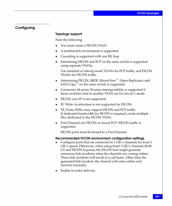
FICON Topologies
Configuring
Topology support
Note the following:
◆ You must create a FICON VSAN.
◆ A multiswitch environment is supported.
◆ Cascading is supported with one ISL hop.
◆ Intermixing FICON and FCP on the same switch is supported using separate VSANs.
Use standard or interop mode VSANs for FCP traffic, and FICON VSANs for FICON traffic.
◆ Intermixing FICON, SRDF, MirrorView™, Open Replicator, and SAN Copy™ on the same switch is supported.
◆ Connectrix M series/B series interoperability is supported if those switches exist in another VSAN set for interop-1 mode.
◆ FICON over IP is not supported.
◆ FC Write Acceleration is not supported for FICON.
◆ TE_Ports/EISLs may support FICON and FCP traffic.If dedicated bandwidth for FICON is required, create multiple ISLs dedicated to the FICON VSAN.
◆ Port Channels for FICON or mixed FCP/FICON traffic is supported.
FICON ports must be bound to a Port Channel.
Recommended FICON environment configuration settings◆ Configure ports that are connected to 1 GB/s channels for fixed 1
GB/s speed. Otherwise, when using fixed 1 GB/s channels (both G5 and FICON Express), the FICON host might generate erroneous link incidents when the channels are coming online. These link incidents will result in a call home. Other than the generated link incident, the channel will come online and function normally.
◆ Enable in-order delivery.
Connectrix MDS series 601
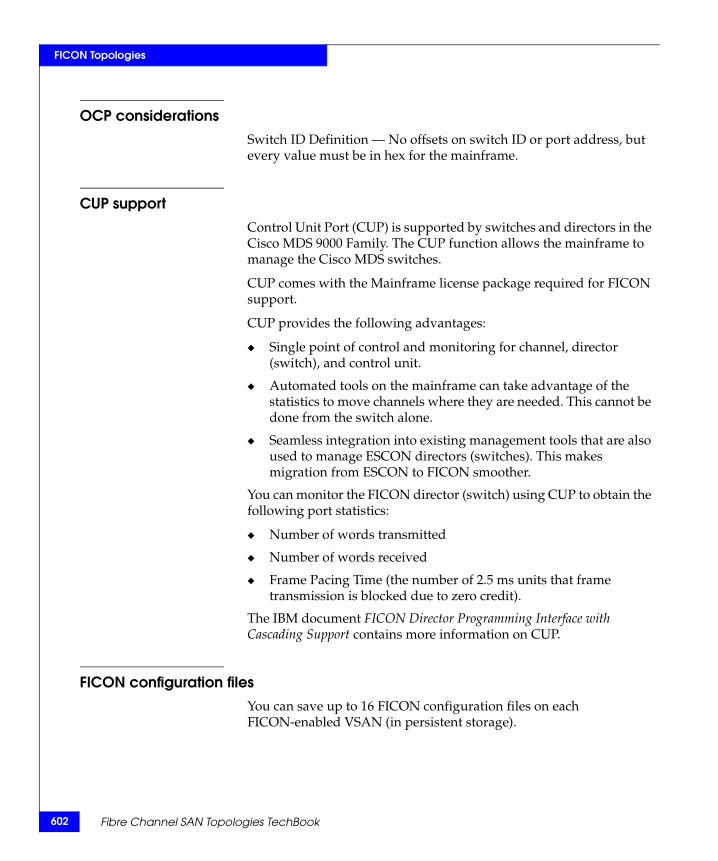
602
FICON Topologies
OCP considerationsSwitch ID Definition — No offsets on switch ID or port address, but every value must be in hex for the mainframe.
CUP supportControl Unit Port (CUP) is supported by switches and directors in the Cisco MDS 9000 Family. The CUP function allows the mainframe to manage the Cisco MDS switches.
CUP comes with the Mainframe license package required for FICON support.
CUP provides the following advantages:
◆ Single point of control and monitoring for channel, director (switch), and control unit.
◆ Automated tools on the mainframe can take advantage of the statistics to move channels where they are needed. This cannot be done from the switch alone.
◆ Seamless integration into existing management tools that are also used to manage ESCON directors (switches). This makes migration from ESCON to FICON smoother.
You can monitor the FICON director (switch) using CUP to obtain the following port statistics:
◆ Number of words transmitted
◆ Number of words received
◆ Frame Pacing Time (the number of 2.5 ms units that frame transmission is blocked due to zero credit).
The IBM document FICON Director Programming Interface with Cascading Support contains more information on CUP.
FICON configuration filesYou can save up to 16 FICON configuration files on each FICON-enabled VSAN (in persistent storage).
Fibre Channel SAN Topologies TechBook
FICON Topologies
FICON configuration files contain the following configuration for each implemented port address:
◆ Block
◆ Prohibit mask
◆ Port address name
Switch node identifierYou can find switch node information, such as the serial number and manufacturer name. This information is the same as the switch node ID in the RNID ELS:
◆ Configuration file information — You can get a list of configuration files on the switch. You can also obtain the actual file content, including port address name and port connectivity.
◆ History summary (director history buffer) — The history buffer logs each change in status or configuration of the ports. You can retrieve the history buffer using CUP.
◆ Switch configuration data — Provides switch configuration data as time-out values and number of ports per card.
You can find more information on CUP functions and commands in the IBM-proprietary document FICON Director Programming Interface With Cascading Support.
Connectrix MDS series 603
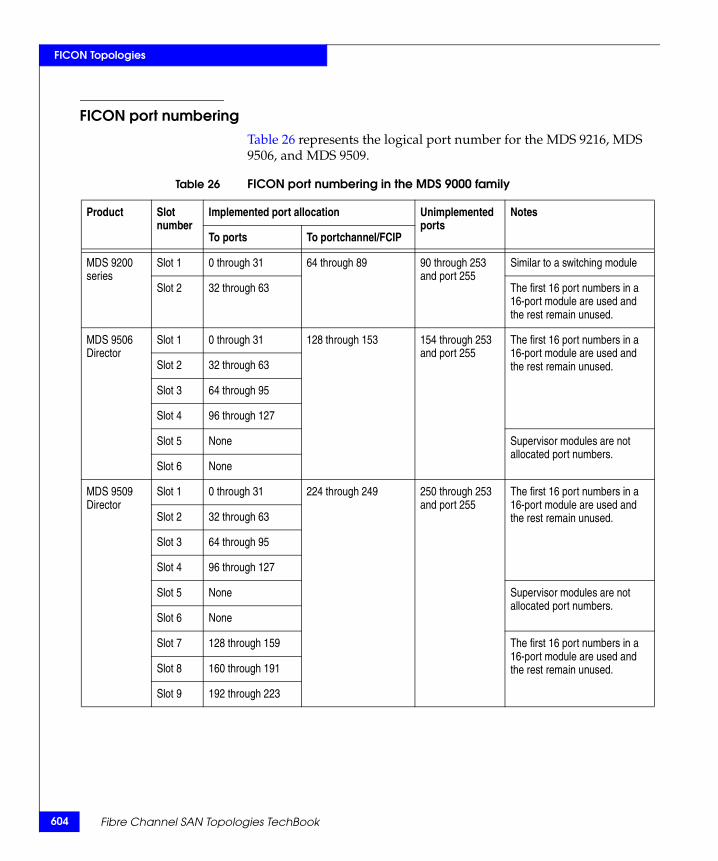
604
FICON Topologies
FICON port numberingTable 26 represents the logical port number for the MDS 9216, MDS 9506, and MDS 9509.
Table 26 FICON port numbering in the MDS 9000 family
Product Slot number
Implemented port allocation Unimplemented ports
Notes
To ports To portchannel/FCIP
MDS 9200 series
Slot 1 0 through 31 64 through 89 90 through 253 and port 255
Similar to a switching module
Slot 2 32 through 63 The first 16 port numbers in a 16-port module are used and the rest remain unused.
MDS 9506 Director
Slot 1 0 through 31 128 through 153 154 through 253 and port 255
The first 16 port numbers in a 16-port module are used and the rest remain unused.Slot 2 32 through 63
Slot 3 64 through 95
Slot 4 96 through 127
Slot 5 None Supervisor modules are not allocated port numbers.
Slot 6 None
MDS 9509 Director
Slot 1 0 through 31 224 through 249 250 through 253 and port 255
The first 16 port numbers in a 16-port module are used and the rest remain unused.Slot 2 32 through 63
Slot 3 64 through 95
Slot 4 96 through 127
Slot 5 None Supervisor modules are not allocated port numbers.
Slot 6 None
Slot 7 128 through 159 The first 16 port numbers in a 16-port module are used and the rest remain unused.Slot 8 160 through 191
Slot 9 192 through 223
Fibre Channel SAN Topologies TechBook
FICON Topologies
ReferencesThese documents and resources contain for more information on FICON connectivity:
◆ E-Lab Navigator, for supported MDS firmware for FICON usage
◆ Connectrix MDS Release Notes, for specific information related to new firmware
◆ Cisco MDS 9000 Family Configuration Guide, available at http://www.Cisco.com
◆ Implementing the Cisco MDS 9000 in an Intermix FCP, FCIP, and FICON Environment (part number SG24-6397-00), available at http://www.redbooks.ibm.com
Connectrix MDS series 605

606
FICON Topologies
Fibre Channel SAN Topologies TechBook
Glossary
This glossary contains terms related to EMC products and EMC networked storage concepts.
Aaccess control A service that allows or prohibits access to a resource. Storage
management products implement access control to allow or prohibit specific users. Storage platform products implement access control, often called LUN Masking, to allow or prohibit access to volumes by Initiators (HBAs). See also “persistent binding” and "zoning."
active domain ID The domain ID actively being used by a switch. It is assigned to a switch by the principal switch.
active zone set The active zone set is the zone set definition currently in effect and enforced by the fabric or other entity (for example, the name server). Only one zone set at a time can be active.
agent An autonomous agent is a system situated within (and is part of) an environment that senses that environment, and acts on it over time in pursuit of its own agenda. Storage management software centralizes the control and monitoring of highly distributed storage infrastructure. The centralizing part of the software management system can depend on agents that are installed on the distributed parts of the infrastructure. For example, an agent (software component) can be installed on each of the hosts (servers) in an environment to allow the centralizing software to control and monitor the hosts.
Fibre Channel SAN Topologies TechBook 607
608
Glossary
alarm An SNMP message notifying an operator of a network problem.
any-to-any portconnectivity
A characteristic of a Fibre Channel switch that allows any port on the switch to communicate with any other port on the same switch.
application Application software is a defined subclass of computer software that employs the capabilities of a computer directly to a task that users want to perform. This is in contrast to system software that participates with integration of various capabilities of a computer, and typically does not directly apply these capabilities to performing tasks that benefit users. The term application refers to both the application software and its implementation which often refers to the use of an information processing system. (For example, a payroll application, an airline reservation application, or a network application.) Typically an application is installed “on top of” an operating system like Windows or LINUX, and contains a user interface.
application-specificintegrated circuit
(ASIC)
A circuit designed for a specific purpose, such as implementing lower-layer Fibre Channel protocols (FC-1 and FC-0). ASICs contrast with general-purpose devices such as memory chips or microprocessors, which can be used in many different applications.
arbitration The process of selecting one respondent from a collection of several candidates that request service concurrently.
ASIC family Different switch hardware platforms that utilize the same port ASIC can be grouped into collections known as an ASIC family. For example, the Fuji ASIC family which consists of the ED-64M and ED-140M run different microprocessors, but both utilize the same port ASIC to provide Fibre Channel connectivity, and are therefore in the same ASIC family. For inter operability concerns, it is useful to understand to which ASIC family a switch belongs.
ASCII ASCII (American Standard Code for Information Interchange), generally pronounced [aeski], is a character encoding based on the English alphabet. ASCII codes represent text in computers, communications equipment, and other devices that work with text. Most modern character encodings, which support many more characters, have a historical basis in ASCII.
audit log A log containing summaries of actions taken by a Connectrix Management software user that creates an audit trail of changes. Adding, modifying, or deleting user or product administration
Fibre Channel SAN Topologies TechBook
Glossary
values, creates a record in the audit log that includes the date and time.
authentication Verification of the identity of a process or person.
Bbackpressure The effect on the environment leading up to the point of restriction.
See "congestion."
BB_Credit See "buffer-to-buffer credit."
beaconing Repeated transmission of a beacon light and message until an error is corrected or bypassed. Typically used by a piece of equipment when an individual Field Replaceable Unit (FRU) needs replacement. Beaconing helps the field engineer locate the specific defective component. Some equipment management software systems such as Connectrix Manager offer beaconing capability.
BER See "bit error rate."
bidirectional In Fibre Channel, the capability to simultaneously communicate at maximum speeds in both directions over a link.
bit error rate Ratio of received bits that contain errors to total of all bits transmitted.
blade server A consolidation of independent servers and switch technology in the same chassis.
blocked port Devices communicating with a blocked port are prevented from logging in to the Fibre Channel switch containing the port or communicating with other devices attached to the switch. A blocked port continuously transmits the off-line sequence (OLS).
bridge A device that provides a translation service between two network segments utilizing different communication protocols. EMC supports and sells bridges that convert iSCSI storage commands from a NIC- attached server to Fibre Channel commands for a storage platform.
broadcast Sends a transmission to all ports in a network. Typically used in IP networks. Not typically used in Fibre Channel networks.
Fibre Channel SAN Topologies TechBook 609
610
Glossary
broadcast frames Data packet, also known as a broadcast packet, whose destination address specifies all computers on a network. See also "multicast."
buffer Storage area for data in transit. Buffers compensate for differences in link speeds and link congestion between devices.
buffer-to-buffer credit The number of receive buffers allocated by a receiving FC_Port to a transmitting FC_Port. The value is negotiated between Fibre Channel ports during link initialization. Each time a port transmits a frame it decrements this credit value. Each time a port receives an R_Rdy frame it increments this credit value. If the credit value is decremented to zero, the transmitter stops sending any new frames until the receiver has transmitted an R_Rdy frame. Buffer-to-buffer credit is particularly important in SRDF and Mirror View distance extension solutions.
CCall Home A product feature that allows the Connectrix service processor to
automatically dial out to a support center and report system problems. The support center server accepts calls from the Connectrix service processor, logs reported events, and can notify one or more support center representatives. Telephone numbers and other information are configured through the Windows NT dial-up networking application. The Call Home function can be enabled and disabled through the Connectrix Product Manager.
channel With Open Systems, a channel is a point-to-point link that transports data from one point to another on the communication path, typically with high throughput and low latency that is generally required by storage systems. With Mainframe environments, a channel refers to the server-side of the server-storage communication path, analogous to the HBA in Open Systems.
Class 2 Fibre Channelclass of service
In Class 2 service, the fabric and destination N_Ports provide connectionless service with notification of delivery or nondelivery between the two N_Ports. Historically Class 2 service is not widely used in Fibre Channel system.
Class 3 Fibre Channelclass of service
Class 3 service provides a connectionless service without notification of delivery between N_Ports. (This is also known as datagram service.) The transmission and routing of Class 3 frames is the same
Fibre Channel SAN Topologies TechBook
Glossary
as for Class 2 frames. Class 3 is the dominant class of communication used in Fibre Channel for moving data between servers and storage and may be referred to as “Ship and pray.”
Class F Fibre Channelclass of service
Class F service is used for all switch-to-switch communication in a multiswitch fabric environment. It is nearly identical to class 2 from a flow control point of view.
community A relationship between an SNMP agent and a set of SNMP managers that defines authentication, access control, and proxy characteristics.
community name A name that represents an SNMP community that the agent software recognizes as a valid source for SNMP requests. An SNMP management program that sends an SNMP request to an agent program must identify the request with a community name that the agent recognizes or the agent discards the message as an authentication failure. The agent counts these failures and reports the count to the manager program upon request, or sends an authentication failure trap message to the manager program.
community profile Information that specifies which management objects are available to what management domain or SNMP community name.
congestion Occurs at the point of restriction. See "backpressure."
connectionless Non dedicated link. Typically used to describe a link between nodes that allows the switch to forward Class 2 or Class 3 frames as resources (ports) allow. Contrast with the dedicated bandwidth that is required in a Class 1 Fibre Channel Service point-to-point link.
Connectivity Unit A hardware component that contains hardware (and possibly software) that provides Fibre Channel connectivity across a fabric. Connectrix switches are example of Connectivity Units. This is a term popularized by the Fibre Alliance MIB, sometimes abbreviated to connunit.
Connectrixmanagement
software
The software application that implements the management user interface for all managed Fibre Channel products, typically the Connectrix -M product line. Connectrix Management software is a client/server application with the server running on the Connectrix service processor, and clients running remotely or on the service processor.
Fibre Channel SAN Topologies TechBook 611
612
Glossary
Connectrix serviceprocessor
An optional 1U server shipped with the Connectrix -M product line to run the Connectrix Management server software and EMC remote support application software.
Control Unit In mainframe environments, a Control Unit controls access to storage. It is analogous to a Target in Open Systems environments.
core switch Occupies central locations within the interconnections of a fabric. Generally provides the primary data paths across the fabric and the direct connections to storage devices. Connectrix directors are typically installed as core switches, but may be located anywhere in the fabric.
credit A numeric value that relates to the number of available BB_Credits on a Fibre Channel port. See“buffer-to-buffer credit”.
DDASD Direct Access Storage Device.
default Pertaining to an attribute, value, or option that is assumed when none is explicitly specified.
default zone A zone containing all attached devices that are not members of any active zone. Typically the default zone is disabled in a Connectrix M environment which prevents newly installed servers and storage from communicating until they have been provisioned.
Dense WavelengthDivision Multiplexing
(DWDM)
A process that carries different data channels at different wavelengths over one pair of fiber optic links. A conventional fiber-optic system carries only one channel over a single wavelength traveling through a single fiber.
destination ID A field in a Fibre Channel header that specifies the destination address for a frame. The Fibre Channel header also contains a Source ID (SID). The FCID for a port contains both the SID and the DID.
device A piece of equipment, such as a server, switch or storage system.
dialog box A user interface element of a software product typically implemented as a pop-up window containing informational messages and fields for modification. Facilitates a dialog between the user and the application. Dialog box is often used interchangeably with window.
Fibre Channel SAN Topologies TechBook
Glossary
DID An acronym used to refer to either Domain ID or Destination ID. This ambiguity can create confusion. As a result E-Lab recommends this acronym be used to apply to Domain ID. Destination ID can be abbreviated to FCID.
director An enterprise-class Fibre Channel switch, such as the Connectrix ED-140M, MDS 9509, or ED-48000B. Directors deliver high availability, failure ride-through, and repair under power to insure maximum uptime for business critical applications. Major assemblies, such as power supplies, fan modules, switch controller cards, switching elements, and port modules, are all hot-swappable.
The term director may also refer to a board-level module in the Symmetrix that provides the interface between host channels (through an associated adapter module in the Symmetrix) and Symmetrix disk devices. (This description is presented here only to clarify a term used in other EMC documents.)
DNS See "domain name service name."
domain ID A byte-wide field in the three byte Fibre Channel address that uniquely identifies a switch in a fabric. The three fields in a FCID are domain, area, and port. A distinct Domain ID is requested from the principal switch. The principal switch allocates one Domain ID to each switch in the fabric. A user may be able to set a Preferred ID which can be requested of the Principal switch, or set an Insistent Domain ID. If two switches insist on the same DID one or both switches will segment from the fabric.
domain name servicename
Host or node name for a system that is translated to an IP address through a name server. All DNS names have a host name component and, if fully qualified, a domain component, such as host1.abcd.com. In this example, host1 is the host name.
dual-attached host A host that has two (or more) connections to a set of devices.
EE_D_TOV A time-out period within which each data frame in a Fibre Channel
sequence transmits. This avoids time-out errors at the destination Nx_Port. This function facilitates high speed recovery from dropped frames. Typically this value is 2 seconds.
Fibre Channel SAN Topologies TechBook 613
614
Glossary
E_Port Expansion Port, a port type in a Fibre Channel switch that attaches to another E_Port on a second Fibre Channel switch forming an Interswitch Link (ISL). This link typically conforms to the FC-SW standards developed by the T11 committee, but might not support heterogeneous inter operability.
edge switch Occupies the periphery of the fabric, generally providing the direct connections to host servers and management workstations. No two edge switches can be connected by interswitch links (ISLs). Connectrix departmental switches are typically installed as edge switches in a multiswitch fabric, but may be located anywhere in the fabric
Embedded WebServer
A management interface embedded on the switch’s code that offers features similar to (but not as robust as) the Connectrix Manager and Product Manager.
error detect time outvalue
Defines the time the switch waits for an expected response before declaring an error condition. The error detect time out value (E_D_TOV) can be set within a range of two-tenths of a second to one second using the Connectrix switch Product Manager.
error message An indication that an error has been detected. See also “information message” and "warning message."
Ethernet A baseband LAN that allows multiple station access to the transmission medium at will without prior coordination and which avoids or resolves contention.
event log A record of significant events that have occurred on a Connectrix switch, such as FRU failures, degraded operation, and port problems.
expansionport See "E_Port."
explicit fabric login In order to join a fabric, an Nport must login to the fabric (an operation referred to as an FLOGI). Typically this is an explicit operation performed by the Nport communicating with the F_port of the switch, and is called an explicit fabric login. Some legacy Fibre Channel ports do not perform explicit login, and switch vendors perform login for ports creating an implicit login. Typically logins are explicit.
Fibre Channel SAN Topologies TechBook

Glossary
FFA Fibre Adapter, another name for a Symmetrix Fibre Channel director.
F_Port Fabric Port, a port type on a Fibre Channel switch. An F_Port attaches to an N_Port through a point-to-point full-duplex link connection. A G_Port automatically becomes an F_port or an E-Port depending on the port initialization process.
fabric One or more switching devices that interconnect Fibre Channel N_Ports, and route Fibre Channel frames based on destination IDs in the frame headers. A fabric provides discovery, path provisioning, and state change management services for a Fibre Channel environment.
fabric element Any active switch or director in the fabric.
fabric login Process used by N_Ports to establish their operating parameters including class of service, speed, and buffer-to-buffer credit value.
fabric port A port type (F_Port) on a Fibre Channel switch that attaches to an N_Port through a point-to-point full-duplex link connection. An N_Port is typically a host (HBA) or a storage device like Symmetrix, VNX™ series, or CLARiiON.
fabric shortest pathfirst (FSPF)
A routing algorithm implemented by Fibre Channel switches in a fabric. The algorithm seeks to minimize the number of hops traversed as a Fibre Channel frame travels from its source to its destination.
fabric tree A hierarchical list in Connectrix Manager of all fabrics currently known to the Connectrix service processor. The tree includes all members of the fabrics, listed by WWN or nickname.
failover The process of detecting a failure on an active Connectrix switch FRU and the automatic transition of functions to a backup FRU.
fan-in/fan-out Term used to describe the server:storage ratio, where a graphic representation of a 1:n (fan-in) or n:1 (fan-out) logical topology looks like a hand-held fan, with the wide end toward n. By convention fan-out refers to the number of server ports that share a single storage port. Fan-out consolidates a large number of server ports on a fewer number of storage ports. Fan-in refers to the number of storage ports that a single server port uses. Fan-in enlarges the storage capacity used by a server. A fan-in or fan-out rate is often referred to as just the
Fibre Channel SAN Topologies TechBook 615
616
Glossary
n part of the ratio; For example, a 16:1 fan-out is also called a fan-out rate of 16, in this case 16 server ports are sharing a single storage port.
FCP See "Fibre Channel Protocol."
FC-SW The Fibre Channel fabric standard. The standard is developed by the T11 organization whose documentation can be found at T11.org. EMC actively participates in T11. T11 is a committee within the InterNational Committee for Information Technology (INCITS).
fiber optics The branch of optical technology concerned with the transmission of radiant power through fibers made of transparent materials such as glass, fused silica, and plastic.
Either a single discrete fiber or a non spatially aligned fiber bundle can be used for each information channel. Such fibers are often called optical fibers to differentiate them from fibers used in non-communication applications.
fibre A general term used to cover all physical media types supported by the Fibre Channel specification, such as optical fiber, twisted pair, and coaxial cable.
Fibre Channel The general name of an integrated set of ANSI standards that define new protocols for flexible information transfer. Logically, Fibre Channel is a high-performance serial data channel.
Fibre ChannelProtocol
A standard Fibre Channel FC-4 level protocol used to run SCSI over Fibre Channel.
Fibre Channel switchmodules
The embedded switch modules in the back plane of the blade server. See “blade server” on page 609.
firmware The program code (embedded software) that resides and executes on a connectivity device, such as a Connectrix switch, a Symmetrix Fibre Channel director, or a host bus adapter (HBA).
F_Port Fabric Port, a physical interface within the fabric. An F_Port attaches to an N_Port through a point-to-point full-duplex link connection.
frame A set of fields making up a unit of transmission. Each field is made of bytes. The typical Fibre Channel frame consists of fields: Start-of-frame, header, data-field, CRC, end-of-frame. The maximum frame size is 2148 bytes.
Fibre Channel SAN Topologies TechBook
Glossary
frame header Control information placed before the data-field when encapsulating data for network transmission. The header provides the source and destination IDs of the frame.
FRU Field-replaceable unit, a hardware component that can be replaced as an entire unit. The Connectrix switch Product Manager can display status for the FRUs installed in the unit.
FSPF Fabric Shortest Path First, an algorithm used for routing traffic. This means that, between the source and destination, only the paths that have the least amount of physical hops will be used for frame delivery.
Ggateway address In TCP/IP, a device that connects two systems that use the same
or different protocols.
gigabyte (GB) A unit of measure for storage size, loosely one billion (109) bytes. One gigabyte actually equals 1,073,741,824 bytes.
G_Port A port type on a Fibre Channel switch capable of acting either as an F_Port or an E_Port, depending on the port type at the other end of the link.
GUI Graphical user interface.
HHBA See "host bus adapter."
hexadecimal Pertaining to a numbering system with base of 16; valid numbers use the digits 0 through 9 and characters A through F (which represent the numbers 10 through 15).
high availability A performance feature characterized by hardware component redundancy and hot-swappability (enabling non-disruptive maintenance). High-availability systems maximize system uptime while providing superior reliability, availability, and serviceability.
hop A hop refers to the number of InterSwitch Links (ISLs) a Fibre Channel frame must traverse to go from its source to its destination.
Fibre Channel SAN Topologies TechBook 617
618
Glossary
Good design practice encourages three hops or less to minimize congestion and performance management complexities.
host bus adapter A bus card in a host system that allows the host system to connect to the storage system. Typically the HBA communicates with the host over a PCI or PCI Express bus and has a single Fibre Channel link to the fabric. The HBA contains an embedded microprocessor with on board firmware, one or more ASICs, and a Small Form Factor Pluggable module (SFP) to connect to the Fibre Channel link.
II/O See "input/output."
in-band management Transmission of monitoring and control functions over the Fibre Channel interface. You can also perform these functions out-of-band typically by use of the ethernet to manage Fibre Channel devices.
information message A message telling a user that a function is performing normally or has completed normally. User acknowledgement might or might not be required, depending on the message. See also “error message” and "warning message."
input/output (1) Pertaining to a device whose parts can perform an input process and an output process at the same time. (2) Pertaining to a functional unit or channel involved in an input process, output process, or both (concurrently or not), and to the data involved in such a process. (3) Pertaining to input, output, or both.
interface (1) A shared boundary between two functional units, defined by functional characteristics, signal characteristics, or other characteristics as appropriate. The concept includes the specification of the connection of two devices having different functions. (2) Hardware, software, or both, that links systems, programs, or devices.
Internet Protocol See "IP."
interoperability The ability to communicate, execute programs, or transfer data between various functional units over a network. Also refers to a Fibre Channel fabric that contains switches from more than one vendor.
Fibre Channel SAN Topologies TechBook
Glossary
interswitch link (ISL) Interswitch link, a physical E_Port connection between any two switches in a Fibre Channel fabric. An ISL forms a hop in a fabric.
IP Internet Protocol, the TCP/IP standard protocol that defines the datagram as the unit of information passed across an internet and provides the basis for connectionless, best-effort packet delivery service. IP includes the ICMP control and error message protocol as an integral part.
IP address A unique string of numbers that identifies a device on a network. The address consists of four groups (quadrants) of numbers delimited by periods. (This is called dotted-decimal notation.) All resources on the network must have an IP address. A valid IP address is in the form nnn.nnn.nnn.nnn, where each nnn is a decimal in the range 0 to 255.
ISL Interswitch link, a physical E_Port connection between any two switches in a Fibre Channel fabric.
Kkilobyte (K) A unit of measure for storage size, loosely one thousand bytes. One
kilobyte actually equals 1,024 bytes.
Llaser A device that produces optical radiation using a population inversion
to provide light amplification by stimulated emission of radiation and (generally) an optical resonant cavity to provide positive feedback. Laser radiation can be highly coherent temporally, spatially, or both.
LED Light-emitting diode.
link The physical connection between two devices on a switched fabric.
link incident A problem detected on a fiber-optic link; for example, loss of light, or invalid sequences.
load balancing The ability to distribute traffic over all network ports that are the same distance from the destination address by assigning different paths to different messages. Increases effective network bandwidth. EMC PowerPath software provides load-balancing services for server IO.
Fibre Channel SAN Topologies TechBook 619
620
Glossary
logical volume A named unit of storage consisting of a logically contiguous set of disk sectors.
Logical Unit Number(LUN)
A number, assigned to a storage volume, that (in combination with the storage device node's World Wide Port Name (WWPN)) represents a unique identifier for a logical volume on a storage area network.
MMAC address Media Access Control address, the hardware address of a device
connected to a shared network.
managed product A hardware product that can be managed using the Connectrix Product Manager. For example, a Connectrix switch is a managed product.
management session Exists when a user logs in to the Connectrix Management software and successfully connects to the product server. The user must specify the network address of the product server at login time.
media The disk surface on which data is stored.
media access control See "MAC address."
megabyte (MB) A unit of measure for storage size, loosely one million (106) bytes. One megabyte actually equals 1,048,576 bytes.
MIB Management Information Base, a related set of objects (variables) containing information about a managed device and accessed through SNMP from a network management station.
multicast Multicast is used when multiple copies of data are to be sent to designated, multiple, destinations.
multiswitch fabric Fibre Channel fabric created by linking more than one switch or director together to allow communication. See also "ISL."
multiswitch linking Port-to-port connections between two switches.
Nname server (dNS) A service known as the distributed Name Server provided by a Fibre
Channel fabric that provides device discovery, path provisioning, and
Fibre Channel SAN Topologies TechBook
Glossary
state change notification services to the N_Ports in the fabric. The service is implemented in a distributed fashion, for example, each switch in a fabric participates in providing the service. The service is addressed by the N_Ports through a Well Known Address.
network address A name or address that identifies a managed product, such as a Connectrix switch, or a Connectrix service processor on a TCP/IP network. The network address can be either an IP address in dotted decimal notation, or a Domain Name Service (DNS) name as administered on a customer network. All DNS names have a host name component and (if fully qualified) a domain component, such as host1.emc.com. In this example, host1 is the host name and EMC.com is the domain component.
nickname A user-defined name representing a specific WWxN, typically used in a Connectrix -M management environment. The analog in the Connectrix -B and MDS environments is alias.
node The point at which one or more functional units connect to the network.
N_Port Node Port, a Fibre Channel port implemented by an end device (node) that can attach to an F_Port or directly to another N_Port through a point-to-point link connection. HBAs and storage systems implement N_Ports that connect to the fabric.
NVRAM Nonvolatile random access memory.
Ooffline sequence
(OLS)The OLS Primitive Sequence is transmitted to indicate that the FC_Port transmitting the Sequence is:
a. initiating the Link Initialization Protocol
b. receiving and recognizing NOS
c. or entering the offline state
OLS See “offline sequence (OLS)”.
operating mode Regulates what other types of switches can share a multiswitch fabric with the switch under consideration.
Fibre Channel SAN Topologies TechBook 621
622
Glossary
operating system Software that controls the execution of programs and that may provide such services as resource allocation, scheduling, input/output control, and data management. Although operating systems are predominantly software, partial hardware implementations are possible.
optical cable A fiber, multiple fibers, or a fiber bundle in a structure built to meet optical, mechanical, and environmental specifications.
OS See "operating system."
out-of-bandmanagement
Transmission of monitoring/control functions outside of the Fibre Channel interface, typically over ethernet.
oversubscription The ratio of bandwidth required to bandwidth available. When all ports, associated pair-wise, in any random fashion, cannot sustain full duplex at full line-rate, the switch is oversubscribed.
Pparameter A characteristic element with a variable value that is given a constant
value for a specified application. Also, a user-specified value for an item in a menu; a value that the system provides when a menu is interpreted; data passed between programs or procedures.
password (1) A value used in authentication or a value used to establish membership in a group having specific privileges. (2) A unique string of characters known to the computer system and to a user who must specify it to gain full or limited access to a system and to the information stored within it.
path In a network, any route between any two nodes.
persistent binding Use of server-level access control configuration information to persistently bind a server device name to a specific Fibre Channel storage volume or logical unit number, through a specific HBA and storage port WWN. The address of a persistently bound device does not shift if a storage target fails to recover during a power cycle. This function is the responsibility of the HBA device driver.
port (1) An access point for data entry or exit. (2) A receptacle on a device to which a cable for another device is attached.
Fibre Channel SAN Topologies TechBook
Glossary
port card Field replaceable hardware component that provides the connection for fiber cables and performs specific device-dependent logic functions.
port name A symbolic name that the user defines for a particular port through the Product Manager.
preferred domain ID An ID configured by the fabric administrator. During the fabric build process a switch requests permission from the principal switch to use its preferred domain ID. The principal switch can deny this request by providing an alternate domain ID only if there is a conflict for the requested Domain ID. Typically a principal switch grants the non-principal switch its requested Preferred Domain ID.
principal downstreamISL
The ISL to which each switch will forward frames originating from the principal switch.
principal ISL The principal ISL is the ISL that frames destined to, or coming from, the principal switch in the fabric will use. An example is an RDI frame.
principal switch In a multiswitch fabric, the switch that allocates domain IDs to itself and to all other switches in the fabric. There is always one principal switch in a fabric. If a switch is not connected to any other switches, it acts as its own principal switch.
principal upstream ISL The ISL to which each switch will forward frames destined for the principal switch. The principal switch does not have any upstream ISLs.
product (1) Connectivity Product, a generic name for a switch, director, or any other Fibre Channel product. (2) Managed Product, a generic hardware product that can be managed by the Product Manager (a Connectrix switch is a managed product). Note distinction from the definition for "device."
Product Manager A software component of Connectrix Manager software such as a Connectrix switch product manager, that implements the management user interface for a specific product. When a product instance is opened from the Connectrix Manager software products view, the corresponding product manager is invoked. The product manager is also known as an Element Manager.
Fibre Channel SAN Topologies TechBook 623
624
Glossary
product name A user configurable identifier assigned to a Managed Product. Typically, this name is stored on the product itself. For a Connectrix switch, the Product Name can also be accessed by an SNMP Manager as the System Name. The Product Name should align with the host name component of a Network Address.
products view The top-level display in the Connectrix Management software user interface that displays icons of Managed Products.
protocol (1) A set of semantic and syntactic rules that determines the behavior of functional units in achieving communication. (2) A specification for the format and relative timing of information exchanged between communicating parties.
RR_A_TOV See "resource allocation time out value."
remote access link The ability to communicate with a data processing facility through a remote data link.
remote notification The system can be programmed to notify remote sites of certain classes of events.
remote userworkstation
A workstation, such as a PC, using Connectrix Management software and Product Manager software that can access the Connectrix service processor over a LAN connection. A user at a remote workstation can perform all of the management and monitoring tasks available to a local user on the Connectrix service processor.
resource allocationtime out value
A value used to time-out operations that depend on a maximum time that an exchange can be delayed in a fabric and still be delivered. The resource allocation time-out value of (R_A_TOV) can be set within a range of two-tenths of a second to 120 seconds using the Connectrix switch product manager. The typical value is 10 seconds.
SSAN See "storage area network (SAN)."
segmentation A non-connection between two switches. Numerous reasons exist for an operational ISL to segment, including interop mode incompatibility, zoning conflicts, and domain overlaps.
Fibre Channel SAN Topologies TechBook
Glossary
segmented E_Port E_Port that has ceased to function as an E_Port within a multiswitch fabric due to an incompatibility between the fabrics that it joins.
service processor See "Connectrix service processor."
session See "management session."
single attached host A host that only has a single connection to a set of devices.
small form factorpluggable (SFP)
An optical module implementing a shortwave or long wave optical transceiver.
SMTP Simple Mail Transfer Protocol, a TCP/IP protocol that allows users to create, send, and receive text messages. SMTP protocols specify how messages are passed across a link from one system to another. They do not specify how the mail application accepts, presents or stores the mail.
SNMP Simple Network Management Protocol, a TCP/IP protocol that generally uses the User Datagram Protocol (UDP) to exchange messages between a management information base (MIB) and a management client residing on a network.
storage area network(SAN)
A network linking servers or workstations to disk arrays, tape backup systems, and other devices, typically over Fibre Channel and consisting of multiple fabrics.
subnet mask Used by a computer to determine whether another computer with which it needs to communicate is located on a local or remote network. The network mask depends upon the class of networks to which the computer is connecting. The mask indicates which digits to look at in a longer network address and allows the router to avoid handling the entire address. Subnet masking allows routers to move the packets more quickly. Typically, a subnet may represent all the machines at one geographic location, in one building, or on the same local area network.
switch priority Value configured into each switch in a fabric that determines its relative likelihood of becoming the fabric’s principal switch.
Fibre Channel SAN Topologies TechBook 625
626
Glossary
TTCP/IP Transmission Control Protocol/Internet Protocol. TCP/IP refers to
the protocols that are used on the Internet and most computer networks. TCP refers to the Transport layer that provides flow control and connection services. IP refers to the Internet Protocol level where addressing and routing are implemented.
toggle To change the state of a feature/function that has only two states. For example, if a feature/function is enabled, toggling changes the state to disabled.
topology Logical and/or physical arrangement of switches on a network.
trap An asynchronous (unsolicited) notification of an event originating on an SNMP-managed device and directed to a centralized SNMP Network Management Station.
Uunblocked port Devices communicating with an unblocked port can log in to a
Connectrix switch or a similar product and communicate with devices attached to any other unblocked port if the devices are in the same zone.
Unicast Unicast routing provides one or more optimal path(s) between any of two switches that make up the fabric. (This is used to send a single copy of the data to designated destinations.)
upper layer protocol(ULP)
The protocol user of FC-4 including IPI, SCSI, IP, and SBCCS. In a device driver ULP typically refers to the operations that are managed by the class level of the driver, not the port level.
URL Uniform Resource Locater, the addressing system used by the World Wide Web. It describes the location of a file or server anywhere on the Internet.
Vvirtual switch A Fibre Channel switch function that allows users to subdivide a
physical switch into multiple virtual switches. Each virtual switch consists of a subset of ports on the physical switch, and has all the properties of a Fibre Channel switch. Multiple virtual switches can be connected through ISL to form a virtual fabric or VSAN.
Fibre Channel SAN Topologies TechBook
Glossary
virtual storage areanetwork (VSAN)
An allocation of switch ports that can span multiple physical switches, and forms a virtual fabric. A single physical switch can sometimes host more than one VSAN.
volume A general term referring to an addressable logically contiguous storage space providing block IO services.
VSAN Virtual Storage Area Network.
Wwarning message An indication that a possible error has been detected. See also “error
message” and "information message."
World Wide Name(WWN)
A unique identifier, even on global networks. The WWN is a 64-bit number (XX:XX:XX:XX:XX:XX:XX:XX). The WWN contains an OUI which uniquely determines the equipment manufacturer. OUIs are administered by the Institute of Electronic and Electrical Engineers (IEEE). The Fibre Channel environment uses two types of WWNs; a World Wide Node Name (WWNN) and a World Wide Port Name (WWPN). Typically the WWPN is used for zoning (path provisioning function).
Zzone An information object implemented by the distributed Nameserver
(dNS) of a Fibre Channel switch. A zone contains a set of members which are permitted to discover and communicate with one another. The members can be identified by a WWPN or port ID. EMC recommends the use of WWPNs in zone management.
zone set An information object implemented by the distributed Nameserver (dNS) of a Fibre Channel switch. A Zone Set contains a set of Zones. A Zone Set is activated against a fabric, and only one Zone Set can be active in a fabric.
zonie A storage administrator who spends a large percentage of his workday zoning a Fibre Channel network and provisioning storage.
zoning Zoning allows an administrator to group several devices by function or by location. All devices connected to a connectivity product, such as a Connectrix switch, may be configured into one or more zones.
Fibre Channel SAN Topologies TechBook 627

628
Glossary
Fibre Channel SAN Topologies TechBook
Index
Bblade switch with direct attached storage 120Bottleneck Detection 408, 420
CCisco Inter VSAN Routing (IVR)
in a heterogeneous environment 347complex Fibre Channel SAN topologies 138compound core edge switches 192core-edge topology, fabric design 554core-edge topology, implementing 554core-edge topology, overview 554CUP (Control Unit Port) 590
Ddefault
maintenance port password 233
EE_Port interoperability 250Edge Hold Time 409
Ffabric resiliency
concepts 416conditions 416features 408thresholds 410
FICONand EMC ControlCenter 589cascading 584
terminology 585topology support 582zoning 583
FICON connectivity 577, 580for Connectrix B series 591for Connectrix M series 594for Connectrix MDS series 600
HHeterogeneous interoperability
in EMC context 251switch 250test information 359
Heterogeneous SAN design 253
IInteroperability modes
EMC-tested 357interoperable switched fabric topology
set up 253IOCP considerations 587
Llatency
detection 420severity 419
Mmaintenance port
configure director network addresses 231default password 233
Fibre Channel SAN Topologies TechBook 629
630
Index
multi-vendor switch configuration 252
Ppassword
default maintenance port 233
SSAN, monitor 399scalable core-edge SAN topology, deploying 558scalable core-edge topology, fabric design 554scalable core-edge topology, implementing 554scalable core-edge topology, overview 554Simple Fibre Channel SAN topologies 38, 40single switch fabrics 40switch
node identifier 593switch configuration
multi-vendor 252
Ttwo switch fabrics 69
Fibre Channel SAN Topologies TechBook
Related Documents