Federal Republic of Nigeria Federal Ministry of Works Highway Manual Part 1: Design Volume VI: Road Traffic Signs and Road Markings 2013 ROAD TRAFFIC SIGNS AND ROAD MARKINGS

Welcome message from author
This document is posted to help you gain knowledge. Please leave a comment to let me know what you think about it! Share it to your friends and learn new things together.
Transcript
Federal Republic of Nigeria
Federal Ministry of Works
Highway Manual Part 1: Design
Volume VI:
Road Traffic Signs and Road Markings
2013
RO
AD
TR
AF
FIC
SIG
NS
AN
D R
OA
D M
AR
KIN
GS


Highway Manual Part 1: Design Volume VI: Road Signs & Markings
FOREWORD
The vision statement of the Federal Ministry of Works is to elevate Nigerian roads to a standard
where they become National economic and socio-political assets, contributing to the Nation’s rapid
growth and development, and to make Federal roads functional, safe, pleasurable, and an avenue for
redeeming Nigerians’ trust and confidence in Government. This vision statement is in tune with the
Transformation Agenda of the President of the Federal Republic of Nigeria, His Excellency, Dr
Goodluck Ebele Jonathan, GCFR. Based on the foregoing, our mission is to use the intellectual,
management and material resources available to the Ministry to make Nigerian roads functional all
the time. The principal goal of the Ministry is to drive the transformation agenda by improving road
transport infrastructure for the overall socio-economic derivable benefits and development of our great
country, Nigeria.
In exercising this mission and in discharging its responsibilities, the Ministry identified the need for
updated and locally relevant standards for the planning, design, construction, maintenance and
operation of our roads, in a sustainable manner. One of the main reference documents for this
purpose is the Highway Manual, which previously included Part 1: Design and Part 2: Maintenance.
Both current parts of the Highway Manual were first published in 1973 and 1980 respectively and
have been subjected to partial updating at various times since then. The passage of time,
development in technology, and a need to capture locally relevant experience and information, in the
context of global best practices, means that a comprehensive update is now warranted.
The purpose of the Highway Manual is to establish the policy of the Government of the Federal
Republic of Nigeria with regard to the development and operation of roads, at the Federal, State and
Local Government levels, respectively. In line with this objective, the Manual aims to guide members
of staff of the Ministry and engineering practitioners, with regard to standards and procedures that the
Government deem acceptable; to direct practitioners to other reference documents of established
practice where the scope of the Manual is exceeded; to provide a nationally recognized standard
reference document; and to provide a ready source of good practice for the development and
operation of roads in a cost effective and environmentally sustainable manner.
The major benefits to be gained in applying the content of the Highway Manual include harmonization
of professional practice and ensuring uniform application of appropriate levels of safety, health,
economy and sustainability, with due consideration to the objective conditions and needs of our
country.
The Manual has been expanded to include an overarching Code of Procedure and a series of
Volumes within each Part that cover the various aspects of development and operation of highways.
By their very nature, the Manual will require periodic updating from time to time, arising from the
dynamic nature of technological development and changes in the field of Highway Engineering.

Highway Manual Part 1: Design Volume VI: Road Signs & Markings
The Ministry therefore welcomes comments and suggestions from concerned bodies, groups or
individuals, on all aspects of the document during the course of its implementation and use. All feed
back received will be carefully reviewed by professional experts with a view to possible incorporation
of amendments in future editions.
Arc. Mike Oziegbe Onolememen, FNIA, FNIM.
Honourable Minister
Federal Ministry of Works,
Abuja, Nigeria
May, 2013
Highway Manual Part 1: Design Volume VI: Road Signs & Markings
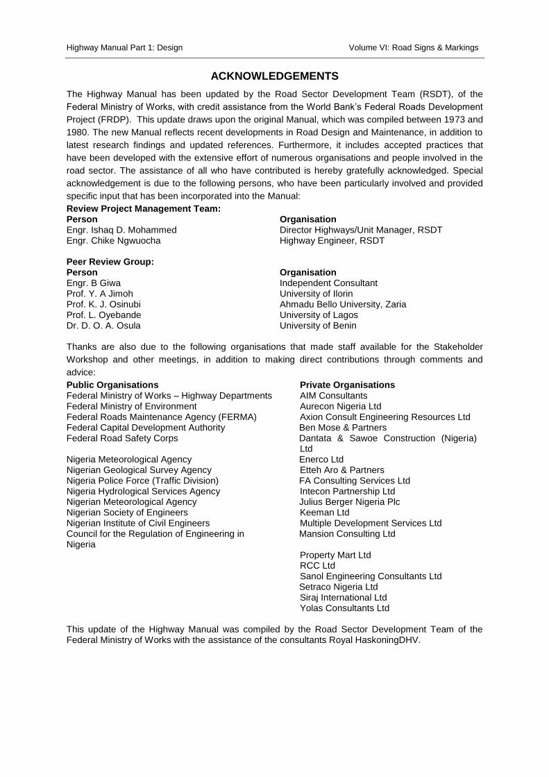
ACKNOWLEDGEMENTS
The Highway Manual has been updated by the Road Sector Development Team (RSDT), of the
Federal Ministry of Works, with credit assistance from the World Bank’s Federal Roads Development
Project (FRDP). This update draws upon the original Manual, which was compiled between 1973 and
1980. The new Manual reflects recent developments in Road Design and Maintenance, in addition to
latest research findings and updated references. Furthermore, it includes accepted practices that
have been developed with the extensive effort of numerous organisations and people involved in the
road sector. The assistance of all who have contributed is hereby gratefully acknowledged. Special
acknowledgement is due to the following persons, who have been particularly involved and provided
specific input that has been incorporated into the Manual:
Review Project Management Team: Person Organisation Engr. Ishaq D. Mohammed Director Highways/Unit Manager, RSDT Engr. Chike Ngwuocha Highway Engineer, RSDT Peer Review Group: Person Organisation Engr. B Giwa Independent Consultant Prof. Y. A Jimoh University of Ilorin Prof. K. J. Osinubi Ahmadu Bello University, Zaria Prof. L. Oyebande University of Lagos Dr. D. O. A. Osula University of Benin Thanks are also due to the following organisations that made staff available for the Stakeholder
Workshop and other meetings, in addition to making direct contributions through comments and
advice:
Public Organisations Private Organisations Federal Ministry of Works – Highway Departments AIM Consultants Federal Ministry of Environment Aurecon Nigeria Ltd Federal Roads Maintenance Agency (FERMA) Axion Consult Engineering Resources Ltd Federal Capital Development Authority Ben Mose & Partners Federal Road Safety Corps Dantata & Sawoe Construction (Nigeria)
Ltd Nigeria Meteorological Agency Enerco Ltd Nigerian Geological Survey Agency Etteh Aro & Partners Nigeria Police Force (Traffic Division) FA Consulting Services Ltd Nigeria Hydrological Services Agency Intecon Partnership Ltd Nigerian Meteorological Agency Julius Berger Nigeria Plc Nigerian Society of Engineers Keeman Ltd Nigerian Institute of Civil Engineers Multiple Development Services Ltd Council for the Regulation of Engineering in Nigeria
Mansion Consulting Ltd
Property Mart Ltd RCC Ltd Sanol Engineering Consultants Ltd Setraco Nigeria Ltd Siraj International Ltd Yolas Consultants Ltd This update of the Highway Manual was compiled by the Road Sector Development Team of the Federal Ministry of Works with the assistance of the consultants Royal HaskoningDHV.

Highway Manual Part 1: Design Volume VI: Road Signs & Markings
i
Table of Contents
TABLE OF CONTENTS ................................................................................................................................ I
TABLE OF FIGURES ................................................................................................................................. IV
LIST OF TABLES......................................................................................................................................... V
1 GENERAL PRINCIPLES ................................................................................................................... 1-1
1.1 DESCRIPTION OF THE HIGHWAY MANUAL .................................................................................................... 1-1
1.1.1 Introduction to the Manual............................................................................................................ 1-1
1.1.2 Arrangement of the Manual .......................................................................................................... 1-1
1.2 OVERVIEW OF VOLUME VI ........................................................................................................................ 1-1
1.3 ROAD SIGNS AND MARKINGS .................................................................................................................... 1-3
1.4 INTERNATIONAL ROAD SIGNS AND MARKINGS .............................................................................................. 1-5
1.5 REQUIREMENTS AND PRINCIPLES FOR TRAFFIC SIGNS AND ROAD MARKINGS ...................................................... 1-5
1.6 CLASSIFICATION OF ROADS, TRAFFIC SIGNS AND ROAD MARKINGS ................................................................... 1-7
2 TRAFFIC SIGNS ................................................................................................................................ 2-1
2.1 REGULATORY SIGNS (PROHIBITORY) ............................................................................................................ 2-1
2.2 REGULATORY SIGNS (MANDATORY) .......................................................................................................... 2-12
2.3 WARNING SIGNS ................................................................................................................................... 2-22
2.4 INFORMATION SIGNS ............................................................................................................................. 2-39
2.5 TEMPORARY ROAD SIGNS ....................................................................................................................... 2-48
3 ROAD MARKINGS ............................................................................................................................ 3-1
3.1 INTRODUCTION ....................................................................................................................................... 3-1
3.2 STOP AND YIELD MARKINGS ...................................................................................................................... 3-2
3.2.1 Stop Lines ....................................................................................................................................... 3-2
3.2.2 Yield Line (Give Way Line) .............................................................................................................. 3-3
3.3 LONGITUDINAL MARKINGS ........................................................................................................................ 3-4
3.3.1 Dividing Lines (Centre Line) ............................................................................................................ 3-4
3.3.2 Traffic Lane Lines ........................................................................................................................... 3-6
3.3.3 Continuity Line (Warning Line) ....................................................................................................... 3-7
3.3.4 Edge of Carriageway Lines ............................................................................................................. 3-8
3.3.5 Painted Traffic Islands .................................................................................................................... 3-9
3.3.6 Exclusive Use Lane ....................................................................................................................... 3-11
3.4 DOUBLE WHITE LINES ............................................................................................................................ 3-11
3.4.1 No Overtaking Lines ..................................................................................................................... 3-11
Highway Manual Part 1: Design Volume VI: Road Signs & Markings
ii
3.4.2 No Crossing Line ........................................................................................................................... 3-16
3.4.3 Channelizing Line ......................................................................................................................... 3-17
3.5 OTHER DELINEATION DEVICES ................................................................................................................. 3-20
3.5.1 Road studs (“Cats Eyes”) .............................................................................................................. 3-20
3.5.2 Guardrail (Crash barrier) Delineators .......................................................................................... 3-21
3.6 INTERSECTIONS ..................................................................................................................................... 3-21
3.6.1 Guide Lines ................................................................................................................................... 3-21
3.6.2 Traffic Circle Arrows ..................................................................................................................... 3-22
3.7 DIRECTION ARROWS AND LANE DESTINATIONS ........................................................................................... 3-22
3.7.1 Direction Arrows .......................................................................................................................... 3-22
3.8 WARNING MARKINGS ............................................................................................................................ 3-24
3.8.1 Word Markings ............................................................................................................................ 3-24
3.9 PEDESTRIAN CROSSINGS ......................................................................................................................... 3-25
3.9.1 Pedestrian Crossings .................................................................................................................... 3-25
3.10 PARKING ............................................................................................................................................. 3-26
3.10.1 Parking Bays ............................................................................................................................ 3-27
4 TRAFFIC SIGNALS ........................................................................................................................... 4-1
4.1 INTRODUCTION ....................................................................................................................................... 4-1
4.2 WARRANTS FOR TRAFFIC SIGNALS .............................................................................................................. 4-3
4.3 VEHICLE SIGNAL INDICATIONS .................................................................................................................... 4-6
4.3.1 Red Light Signals ............................................................................................................................ 4-6
4.3.2 Yellow Light Signals ........................................................................................................................ 4-6
4.3.3 Green Light Signals ........................................................................................................................ 4-7
4.3.4 Yellow and Red Light Signals Shown Together .............................................................................. 4-7
4.3.5 Flashing or other Modes of Operation ........................................................................................... 4-8
4.3.6 Arrangement of Light Signals ........................................................................................................ 4-8
4.3.7 Pedestrian and Pedal Cyclist Signals ............................................................................................ 4-10
4.4 LOCATION AND VISIBILITY OF TRAFFIC SIGNALS ........................................................................................... 4-10
4.4.1 Number and Location of Traffic Signal Faces ............................................................................... 4-11
4.4.2 Visibility and Mounting of Traffic Signal Faces ............................................................................ 4-12
4.5 TRAFFIC SIGNAL TIMINGS AND PHASING .................................................................................................... 4-18
5 APPLICATION OF TRAFFIC SIGNS, ROAD MARKINGS AND SIGNALS ................................. 5-1
5.1 LONGITUDINAL PLACEMENT ...................................................................................................................... 5-1
5.1.1 Longitudinal Placement of Regulatory and Warning Signs ............................................................ 5-1
5.1.2 Longitudinal Placement of Information Signs ................................................................................ 5-2
5.2 LATERAL AND VERTICAL PLACEMENT ......................................................................................................... 5-11
Highway Manual Part 1: Design Volume VI: Road Signs & Markings
iii
5.2.1 Lateral Placement ........................................................................................................................ 5-11
5.2.2 Vertical Placement ....................................................................................................................... 5-16
5.3 SIZES AND DESIGN OF REGULATORY AND WARNING SIGNS ............................................................................ 5-19
5.4 DESIGN OF INFORMATION SIGNS .............................................................................................................. 5-21
5.5 TYPICAL APPLICATIONS AT INTERSECTIONS ................................................................................................. 5-28
5.6 CHECKLIST FOR ROAD DESIGN - TRAFFIC SIGNS AND MARKINGS DRAWINGS ..................................................... 5-35
6 MATERIALS AND INSTALLATION ................................................................................................. 6-1
6.1 TRAFFIC SIGN MATERIALS ......................................................................................................................... 6-1
6.2 ROAD MARKING MATERIALS ..................................................................................................................... 6-2
6.3 INSTALLATION OF ROAD SIGNS ................................................................................................................... 6-3
7 BIBLIOGRAPHY ................................................................................................................................ 7-1
Highway Manual Part 1: Design Volume VI: Road Signs & Markings
iv
List of Figures
FIGURE 1.1: ARRANGEMENT OF HIGHWAY MANUAL ....................................................................................................... 1-2
FIGURE 1.2: SIGNS CLASSIFICATION ........................................................................................................................... 1-10
FIGURE 3.2: YIELD LINE ............................................................................................................................................. 3-3
FIGURE 3.3: YIELD MARKING ...................................................................................................................................... 3-4
FIGURE 3.5: TRAFFIC LANE LINES................................................................................................................................. 3-7
FIGURE 3.6: CONTINUITY LINE .................................................................................................................................... 3-8
FIGURE 3.7: LEFT EDGE / RIGHT EDGE LINES ................................................................................................................. 3-9
FIGURE 3.8: PAINTED ISLAND ................................................................................................................................... 3-10
FIGURE 3.9: EXCLUSIVE LANE ................................................................................................................................... 3-11
FIGURE 3.10: NO OVERTAKING LINES FOR VERTICAL CURVES ......................................................................................... 3-14
FIGURE 3.11: NO OVERTAKING LINES FOR HORIZONTAL CURVES ..................................................................................... 3-15
FIGURE 3.12: NO OVERTAKING LINE .......................................................................................................................... 3-16
FIGURE 3.13: NO CROSSING LINE .............................................................................................................................. 3-17
FIGURE 3.14: CHANNELIZING LINE ............................................................................................................................. 3-18
FIGURE 3.15: TYPICAL CHANNELIZING LINE AT AN EXIT RAMP ......................................................................................... 3-19
FIGURE 3.16: GUIDE LINES ...................................................................................................................................... 3-22
FIGURE 3.17: ARROW MARKING TEMPLATE ................................................................................................................ 3-24
FIGURE 3.18: TEMPLATE FOR WORD MARKING ........................................................................................................... 3-25
FIGURE 3.19: PEDESTRIAN CROSSING......................................................................................................................... 3-26
FIGURE 3.20: PARKING BAYS .................................................................................................................................... 3-27
FIGURE 4.1: NIGERIAN TRAFFIC LIGHT SYSTEM .............................................................................................................. 4-6
FIGURE 4.2: EXAMPLE OF STEADY ARROW SIGNALS ........................................................................................................ 4-7
FIGURE 4.3: STANDARD SIGNAL FACE ........................................................................................................................... 4-9
FIGURE 4.4: SIGNAL FACE WITH ARROWS ..................................................................................................................... 4-9
FIGURE 4.5: SIGNAL GROUPS ................................................................................................................................... 4-10
FIGURE 4.6: STANDARD POST MOUNTING .................................................................................................................. 4-14
FIGURE 4.7: EXTENDED POST MOUNTING ................................................................................................................... 4-15
FIGURE 4.8: OVERHEAD (CANTILEVER) MOUNTING ...................................................................................................... 4-16
FIGURE 4.9: MOUNTING OF A PEDESTRIAN OR PEDAL CYCLE LIGHT SIGNAL ....................................................................... 4-17
FIGURE 4.10: EXAMPLE OF TRAFFIC SIGNAL LAYOUT PLAN ............................................................................................. 4-18
FIGURE 5.1: JUNCTION INFORMATION SIGN SEQUENCE: CLASS C OR D ROAD ...................................................................... 5-4
FIGURE 5.2: GROUND MOUNTED EXIT DIRECTION SIGNS: CLASS A OR B ROAD ACCESS INTERCHANGE ..................................... 5-6
FIGURE 5.3: OFF-RAMP DIRECTION SIGNING ................................................................................................................. 5-7
FIGURE 5.4: GROUND MOUNTED CROSS DIRECTION SIGN SEQUENCE – DIAMOND INTERCHANGE ........................................... 5-8
Highway Manual Part 1: Design Volume VI: Road Signs & Markings
v
FIGURE 5.5: OVERHEAD EXIT DIRECTION SIGN SEQUENCE – ACCESS INTERCHANGE ............................................................... 5-9
FIGURE 5.6: OVERHEAD DIRECTION SIGN SEQUENCE: SYSTEMS INTERCHANGE ................................................................... 5-10
FIGURE 5.7: GROUND MOUNTED CROSS ROAD DIRECTION SIGN SEQUENCE – PARCLO INTERCHANGE .................................... 5-11
FIGURE 5.8: PLACEMENT OF REGULATORY AND WARNING SIGNS (SHOULDER) ................................................................... 5-12
FIGURE 5.9: PLACEMENT OF REGULATORY AND WARNING SIGNS (KERB AND SIDEWALK) ..................................................... 5-13
FIGURE 5.11: PLACEMENT OF MULTIPLE SUPPORT INFORMATION SIGNS .......................................................................... 5-15
FIGURE 5.12: PLACEMENT OF MULTIPLE SUPPORT INFORMATION SIGNS .......................................................................... 5-15
FIGURE 5.13: PLACEMENT OF OVERHEAD CANTILEVER SIGNS ......................................................................................... 5-17
FIGURE 5.14: PLACEMENT OF OVERHEAD GANTRY SIGNS .............................................................................................. 5-18
FIGURE 5.15: TYPICAL UK HIGHWAY NETWORK SIGNAGE .............................................................................................. 5-22
FIGURE 5.16: TYPICAL INFORMATION SIGN DESIGNS USING TRAFSOFT ............................................................................. 5-28
FIGURE 5.17: MINOR CROSSROAD JUNCTION .............................................................................................................. 5-29
FIGURE 5.18: MINOR T-JUNCTION ............................................................................................................................ 5-30
FIGURE 5.19: CROSS ROAD JUNCTION WITH LEFT TURN LANES ....................................................................................... 5-31
FIGURE 5.20: CROSSROAD JUNCTION WITH 4-LANE MAJOR ROAD .................................................................................. 5-32
FIGURE 5.21: TRAFFIC CIRCLE ................................................................................................................................... 5-33
FIGURE 5.22: SIGNALIZED MULTI LANE ROAD ............................................................................................................. 5-34
LIST OF TABLES
TABLE 1.1: PROPOSED NIGERIA ROAD CLASS ................................................................................................................. 1-8
TABLE 3.1: MODULE DIMENSION FOR DIVIDING LINE ...................................................................................................... 3-5
TABLE 3.2: MODULE DIMENSION FOR LANE LINE ........................................................................................................... 3-6
TABLE 3.3: BARRIER SIGHT DISTANCE FOR NO OVERTAKING LINE .................................................................................... 3-13
TABLE 3.4: RECOMMENDED SYMBOL LENGTHS ............................................................................................................ 3-23
TABLE 4.1: SIGHT DISTANCES FOR TRAFFIC SIGNALS ...................................................................................................... 4-13
TABLE 5.1: SIGHT DISTANCES FOR WARNING SIGNS ........................................................................................................ 5-2
TABLE 5.2: DISTANCE OF ADVANCE DIRECTION SIGNS FROM A ROAD JUNCTION ................................................................... 5-5
TABLE 5.3: PERMANENT SIGN PLACEMENT DIMENSIONS (REGULATORY AND WARNING SIGNS) ............................................ 5-14
TABLE 5.4: PERMANENT SIGN PLACEMENT DIMENSIONS (GROUND MOUNTED INFORMATION SIGNS) .................................... 5-16
TABLE 5.5: PERMANENT SIGN PLACEMENT DIMENSIONS (OVERHEAD .............................................................................. 5-19
TABLE 5.7: SIZES OF WARNING SIGNS ........................................................................................................................ 5-20
TABLE 5.8: WIDTH OF SIGN BORDERS (MM) ................................................................................................................ 5-20
TABLE 5.9: RECOMMENDED (AVERAGE) LETTER SIZES – RURAL ROADS ............................................................................ 5-24
TABLE 5.10: RECOMMENDED (AVERAGE) LETTER SIZES – URBAN ROADS ......................................................................... 5-26
TABLE 5.11: SIGNS AND MARKINGS CHECK LIST ........................................................................................................... 5-35
TABLE 6.1: EXAMPLE SUPPORTING STRUCTURE FOR SIGNS ............................................................................................... 6-5

Highway Manual Part 1: Design Volume VI: Signs & Markings
1-1
1 General Principles
1.1 Description of the Highway Manual
1.1.1 Introduction to the Manual
The Highway Manual aims to guide members of staff of the Ministry
and engineering practitioners, with regard to standards and
procedures that the Government deems acceptable for the
planning, design, construction, maintenance, operation and
management of roads. The Manual directs practitioners to other
reference documents of established practice where the scope of the
Manual is exceeded; provides a nationally recognized standard
reference document; and provides a ready source of good practice
for the development and operation of roads in a cost effective and
environmentally sustainable manner.
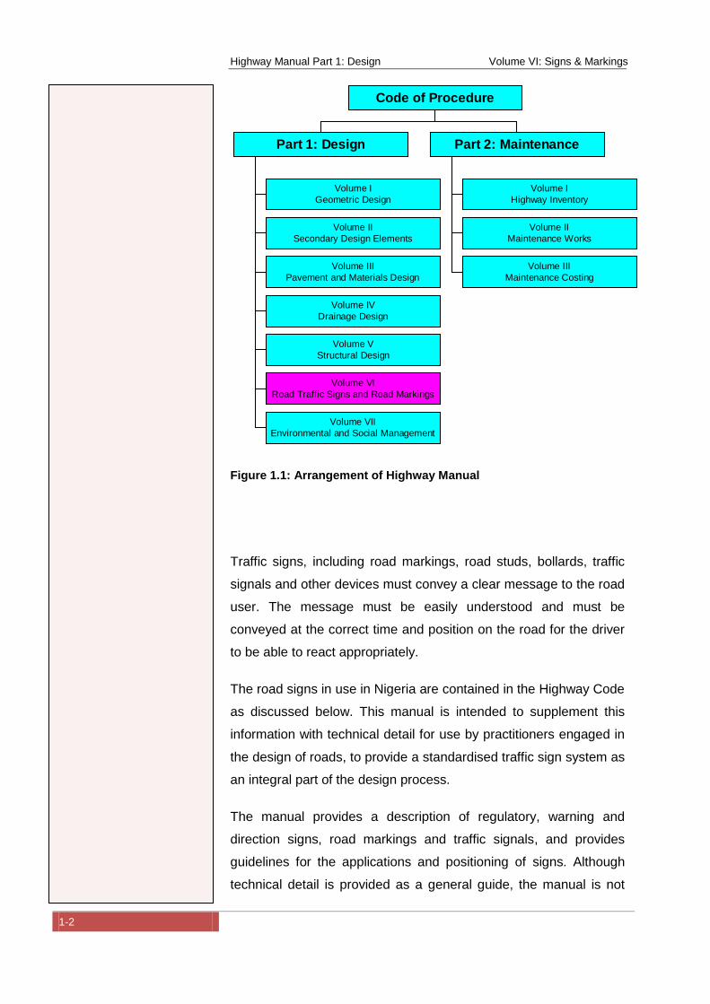
1.1.2 Arrangement of the Manual
The Highway Manual comprises a Code of Procedure and two
Parts, each of which has been divided up into separate volumes, in
the manner shown in Figure 1.1Error! Reference source not
found..
1.2 Overview of Volume VI
The provision of traffic signs and road markings is essential for the
efficient and safe operation of the road network. Roads with poor
signage or badly maintained signs are unsatisfactory roads and
cannot operate to their full traffic carrying potential and capacity.
Standardised traffic signage and road markings are a prerequisite
for effective traffic control and law enforcement.
Highway Manual Part 1: Design Volume VI: Signs & Markings
1-2
Figure 1.1: Arrangement of Highway Manual
Traffic signs, including road markings, road studs, bollards, traffic
signals and other devices must convey a clear message to the road
user. The message must be easily understood and must be
conveyed at the correct time and position on the road for the driver
to be able to react appropriately.
The road signs in use in Nigeria are contained in the Highway Code
as discussed below. This manual is intended to supplement this
information with technical detail for use by practitioners engaged in
the design of roads, to provide a standardised traffic sign system as
an integral part of the design process.
The manual provides a description of regulatory, warning and
direction signs, road markings and traffic signals, and provides
guidelines for the applications and positioning of signs. Although
technical detail is provided as a general guide, the manual is not
Volume I
Geometric Design
Volume II
Secondary Design Elements
Volume III
Pavement and Materials Design
Volume IV
Drainage Design
Volume V
Structural Design
Volume VI
Road Traffic Signs and Road Markings
Volume VII
Environmental and Social Management
Part 1: Design
Volume I
Highway Inventory
Volume II
Maintenance Works
Volume III
Maintenance Costing
Part 2: Maintenance
Code of Procedure
Highway Manual Part 1: Design Volume VI: Signs & Markings
1-3
intended to replace authoritative reference works that are generally
available, but provides guidance as to where additional information
can be obtained if required. Furthermore, modern design methods
make extensive use of computer software to carry out designs, and
there are several packages available that can provide readymade
technical solutions to most signage design problems. References
are thus provided to appropriate software sources.
1.3 Road Signs and Markings
The Federal Republic of Nigeria is a signatory to the Vienna
Convention on Road Signs and Signals, agreed upon by the United
Nations Economic and Social Council at its Conference on Road
Traffic in Vienna, from 7 October 1968 to 8 November 1968, which
came into force on 6 June 1978. The convention revised and
substantially extended the earlier 1949 Geneva Protocol on Road
Signs and Signals, itself based in turn on the 1931 Geneva
Convention concerning the Unification of Road Signals.(Wikipedia)
This is an international treaty designed to increase road safety and
aid international road traffic by standardising the signing system for
road traffic (road signs, traffic lights and road markings) in use
internationally.
The traffic signs and road markings in use in Nigeria, based on the
Convention, are contained in Schedule 9 of the National Road
Traffic Regulations promulgated in the Federal Republic of Nigeria,
Official Gazette No. 79, dated 21 September 2004, Government
Notice No. 335, National Road Traffic Regulations 2004. Regulation
26(2) (h), Schedule 9 deals with the following:
Road Markings: Edge and Lane Lines
Traffic Light Signals
o Regulatory Road Signs
o Prohibitory and Mandatory Road Signs
o Traffic Road Signs
Highway Manual Part 1: Design Volume VI: Signs & Markings
1-4
o Warning Road Signs and
o Informative Road Signs
Signs, signals and road markings are published for the road user
in the Nigeria Highway Code published by the Federal Republic
of Nigeria, Federal Road Safety Commission (Commission, 2008). It is
compulsory in Nigeria for every road user to acquire this
document as a companion and for training purposes.
Nigeria’s total road network is estimated to be 194 000
kilometres of Federal, State and local roads, and in 2011 Nigeria
had the second largest road network in Africa. Between 1978
and 1987 the motor vehicle fleet is reported to have increased by
183 percent as a result of increased motor vehicle ownership.
Approximately 90 percent of passengers and freight rely on the
road network for transportation (Corps, 2012). According to the
Nigeria Road Safety Strategy 2012, the average fatality rate on
Nigeria’s roads over the last five years is five per 100 000
population i.e. an average of 5 000 deaths and 21 000 injuries
per annum.
One of the strategic goals contained in the Nigeria Road Safety
Strategy 2012 is to improve road infrastructure for all users by,
inter alia, defining design standards for all roads and performing
safety assessments on roads. This includes the strategic
activities of developing and implementing national standards on
traffic signs and road markings based on the recommendations
of the Geneva Convention, and preventing the defacement of
road signs and illegal construction of speed bumps on highways.
This manual provides a national standard for traffic signs and
road markings and sets out a practical methodology for the
application of the Nigeria traffic signs and road markings on
Nigeria’s highway and road network, with the objectives of
achieving standardization between implementing authorities, the
improvement of traffic signage and road markings in Nigeria, and
contributing to the reduction of road accidents.
Highway Manual Part 1: Design Volume VI: Signs & Markings
1-5
1.4 International Road Signs and Markings
The Vienna Convention on Road Signs and Signals (United-Nations, 2006)
provides the standard symbols for signs and instructions for their
use. The standards describe the colours of regulatory and
prohibitory traffic signs as having a red border with the ground
being either white or yellow. In Nigeria the colour convention
adopted is the yellow ground.
Although based on the same convention, the signs used in Nigeria
are different to those used in the United Kingdom, and other
European countries, for example, where a white background is
used for warning and regulatory signs as opposed to the yellow
background used in Nigeria. One of the main considerations when
considering the standardization of traffic signs is the need to
harmonize with the convention adopted in neighbouring states,
particularly those with whom a country has strong economic ties.
The Southern African Development Community (SADC) has
adopted the signs convention contained in the SADC Road Traffic
Signs Manual (Department of Transport, South Africa, May 2012), which are similar to
the United Kingdom standard. Angola, Botswana, Congo, Lesotho,
Malawi, Mauritius, Mozambique, Namibia, Seychelles, South Africa,
Tanzania, Zambia and Zimbabwe comprise the SADC.
1.5 Requirements and Principles for Traffic Signs and Road
Markings
The function of traffic signs and road markings is to regulate traffic,
warn road users of hazards and regulations ahead and to guide
traffic by indicating direction and distance. In order to fulfil these
functions, signs and markings should be needed in a particular
situation, be clear and be adhered to by the motorist. Signs and
markings should therefore be properly designed and be appropriate
for a particular situation. They should also be well maintained.

Highway Manual Part 1: Design Volume VI: Signs & Markings
1-6
Signs and markings must comply with national standards
throughout the area or country where they are implemented so that
road users are assured of the same standards wherever they are.
They must also be clear and convey an easily understood
message. They must also be uniform in layout and colour.
It is also important that not too many signs be used and that they
are only installed where they are really effective. However, some
signs need to be installed at regular intervals in order to provide
continuity e.g. navigational information.
The application of signs and markings should also be uniform and
similar situations must be treated in the same way. Uniformity is
also important for law enforcement and traffic safety.
Traffic signs and road markings must only be erected by an
appropriate authority having official jurisdiction. No advertising
should be affixed to a traffic sign or its supports.
The following general principles should be adhered to:
Symbols or diagrams should be used in preference to words
Signs should have the same appearance by day as by night e.g.
by the use of retro-reflective material
The amount of information on a sign should be limited to that
which can easily be absorbed by a motorist.
In order for the information (guidance) signing system to be
effective, a navigation system needs to be developed for Nigeria. A
navigation system would comprise the following:
The classification and numbering of the main road network
The preparation of a map indicating the major routes and
route numbers
The identification and classification of nodes and destinations
to be used on information signs.
Highway Manual Part 1: Design Volume VI: Signs & Markings
1-7
The above would enable local motorists and visitors to plan their
routes and to find their destinations using information signs system
based on the route numbering and destination classification.
The preparation of a navigation system is not within the scope of
this document.
1.6 Classification of Roads, Traffic Signs and Road Markings
The Nigerian road network can be divided into the following classes
according to their major function in the road network (refer to
Volume 1: Geometric Design, Chapter 2 for a full description) as
indicated in Table 1.1:
The road classification is important because the different
classifications have different requirements in respect of traffic signs
and road markings. The positioning of signs depends on sight
distance which is governed by the design speed of the road e.g.
expressways may have a design speed of 100 to 120km/hr
whereas minor roads have a speed limit of 60km/hr.
Higher order roads should have larger signs commensurate with
the higher design speed (See Table 5.6 and Table 5.7) and
information signs (direction and advance direction signs) will be
more complex due to the presence of interchanges.
The following sections will provide guidelines for the positioning and
sizing of signs according to road classification and hence design
speed.
Highway Manual Part 1: Design Volume VI: Signs & Markings
1-8
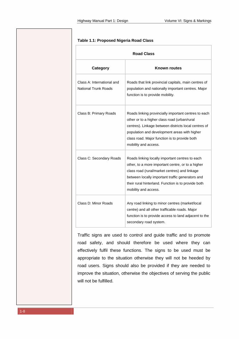
Table 1.1: Proposed Nigeria Road Class
Road Class
Category Known routes
Class A: International and
National Trunk Roads
Roads that link provincial capitals, main centres of
population and nationally important centres. Major
function is to provide mobility.
Class B: Primary Roads
Roads linking provincially important centres to each
other or to a higher class road (urban/rural
centres). Linkage between districts local centres of
population and development areas with higher
class road. Major function is to provide both
mobility and access.
Class C: Secondary Roads
Roads linking locally important centres to each
other, to a more important centre, or to a higher
class road (rural/market centres) and linkage
between locally important traffic generators and
their rural hinterland. Function is to provide both
mobility and access.
Class D: Minor Roads
Any road linking to minor centres (market/local
centre) and all other trafficable roads. Major
function is to provide access to land adjacent to the
secondary road system.
Traffic signs are used to control and guide traffic and to promote
road safety, and should therefore be used where they can
effectively fulfil these functions. The signs to be used must be
appropriate to the situation otherwise they will not be heeded by
road users. Signs should also be provided if they are needed to
improve the situation, otherwise the objectives of serving the public
will not be fulfilled.
Highway Manual Part 1: Design Volume VI: Signs & Markings
1-9
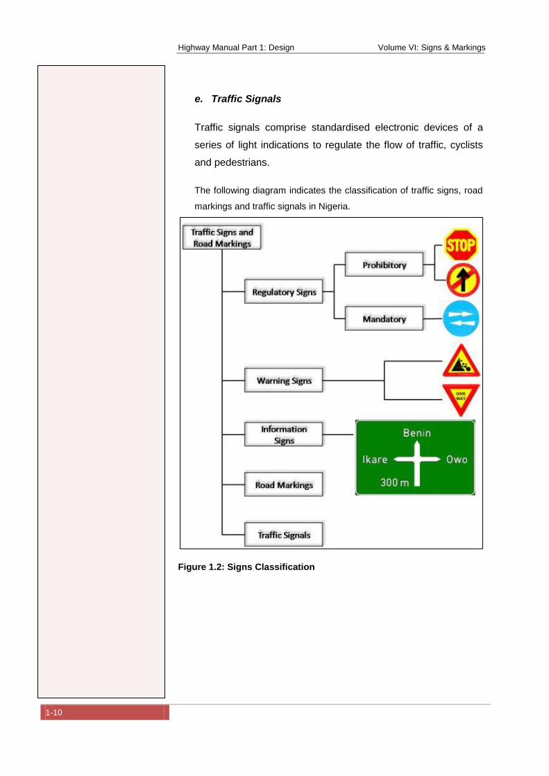
In Nigeria there are three basic classifications of road signs, based
on the Vienna Convention on Road Signs and Signals, as
mentioned in the above sections. These are:
a. Regulatory Signs
These include all signs which give notice of requirements,
prohibitions or restrictions. They may be either mandatory or
prohibitory. Regulatory signs are basically circular in shape and
may be supplemented by plates beneath them augmenting the
message given by the sign. The exception to this is the STOP sign
which is hexagonal.
b. Warning Signs
These signs give warning of a hazard ahead. The design of most
warning signs is based on an equilateral triangle having its apex
uppermost. The exception to this is the YIELD (GIVE WAY) sign
which is an inverted triangle (apex lowermost). They are sometimes
supplemented by rectangular plates giving additional information as
may be necessary.
c. Information Signs
These signs normally give road users information about the route
and about places and facilities of particular value or interest. Most
information signs are rectangular but some direction signs
(FINGERBOARDS) have one end pointed to indicate direction.
d. Road Markings
Road markings are paint, other materials applied to the road
surface, road studs or delineators for the purpose of guiding,
warning or regulating traffic. Road markings can be used on their
own or in combination with traffic signs.
Highway Manual Part 1: Design Volume VI: Signs & Markings
1-10
e. Traffic Signals
Traffic signals comprise standardised electronic devices of a
series of light indications to regulate the flow of traffic, cyclists
and pedestrians.
The following diagram indicates the classification of traffic signs, road
markings and traffic signals in Nigeria.
Figure 1.2: Signs Classification
Highway Manual Part 1: Design Volume VI: Signs & Markings
2-1
2 Traffic Signs
2.1 Regulatory Signs (Prohibitory)
The Regulatory (Prohibitory) signs currently adopted for use in
Nigeria are presented below in terms of the sign number (cross
referenced to the Convention on Traffic Signs (United-Nations, 2006)),
function, requirements, colour and diagrammatic representation.
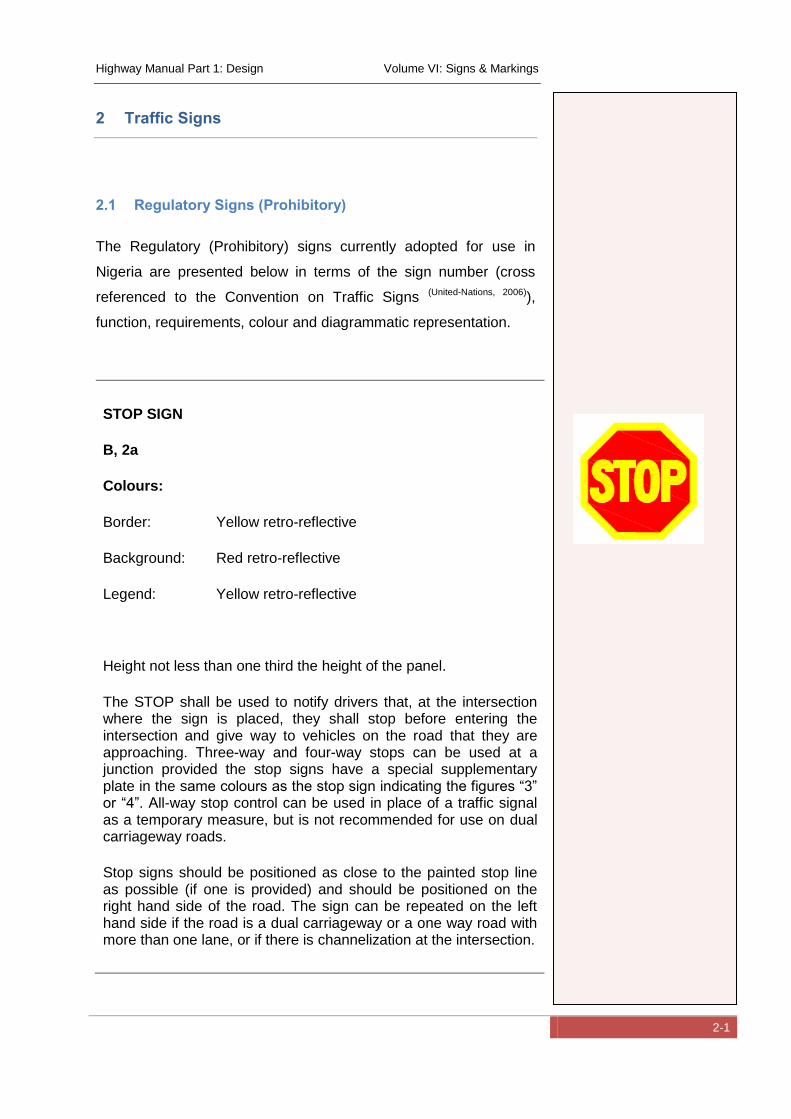
STOP SIGN
B, 2a
Colours:
Border: Yellow retro-reflective
Background: Red retro-reflective
Legend: Yellow retro-reflective
Height not less than one third the height of the panel.
The STOP shall be used to notify drivers that, at the intersection where the sign is placed, they shall stop before entering the intersection and give way to vehicles on the road that they are approaching. Three-way and four-way stops can be used at a junction provided the stop signs have a special supplementary plate in the same colours as the stop sign indicating the figures “3” or “4”. All-way stop control can be used in place of a traffic signal as a temporary measure, but is not recommended for use on dual carriageway roads.
Stop signs should be positioned as close to the painted stop line as possible (if one is provided) and should be positioned on the right hand side of the road. The sign can be repeated on the left hand side if the road is a dual carriageway or a one way road with more than one lane, or if there is channelization at the intersection.
Highway Manual Part 1: Design Volume VI: Signs & Markings
2-2
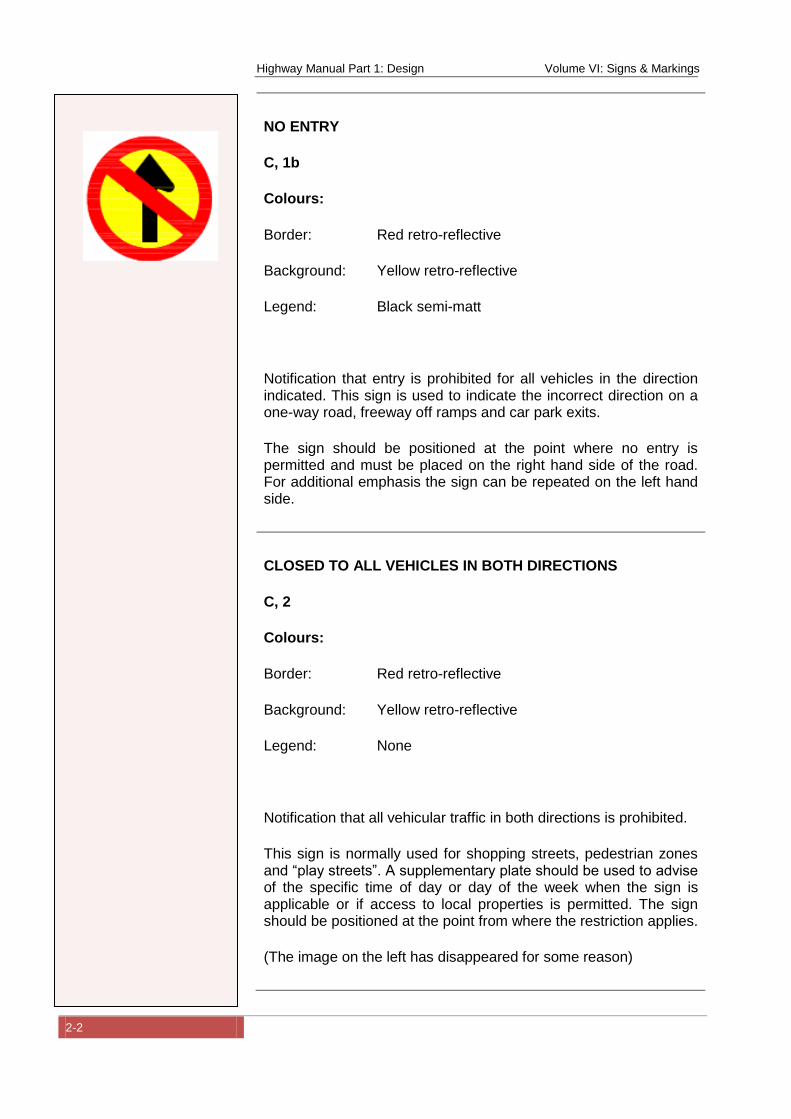
NO ENTRY
C, 1b
Colours:
Border: Red retro-reflective
Background: Yellow retro-reflective
Legend: Black semi-matt
Notification that entry is prohibited for all vehicles in the direction indicated. This sign is used to indicate the incorrect direction on a one-way road, freeway off ramps and car park exits.
The sign should be positioned at the point where no entry is permitted and must be placed on the right hand side of the road. For additional emphasis the sign can be repeated on the left hand side.
CLOSED TO ALL VEHICLES IN BOTH DIRECTIONS
C, 2
Colours:
Border: Red retro-reflective
Background: Yellow retro-reflective
Legend: None
Notification that all vehicular traffic in both directions is prohibited.
This sign is normally used for shopping streets, pedestrian zones and “play streets”. A supplementary plate should be used to advise of the specific time of day or day of the week when the sign is applicable or if access to local properties is permitted. The sign should be positioned at the point from where the restriction applies.
(The image on the left has disappeared for some reason)
Highway Manual Part 1: Design Volume VI: Signs & Markings
2-3
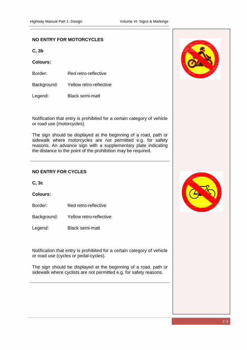
NO ENTRY FOR MOTORCYCLES
C, 3b
Colours:
Border: Red retro-reflective
Background: Yellow retro-reflective
Legend: Black semi-matt
Notification that entry is prohibited for a certain category of vehicle or road use (motorcycles).
The sign should be displayed at the beginning of a road, path or sidewalk where motorcycles are not permitted e.g. for safety reasons. An advance sign with a supplementary plate indicating the distance to the point of the prohibition may be required.
NO ENTRY FOR CYCLES
C, 3c
Colours:
Border: Red retro-reflective
Background: Yellow retro-reflective
Legend: Black semi-matt
Notification that entry is prohibited for a certain category of vehicle or road use (cycles or pedal-cycles).
The sign should be displayed at the beginning of a road, path or sidewalk where cyclists are not permitted e.g. for safety reasons.
Highway Manual Part 1: Design Volume VI: Signs & Markings
2-4
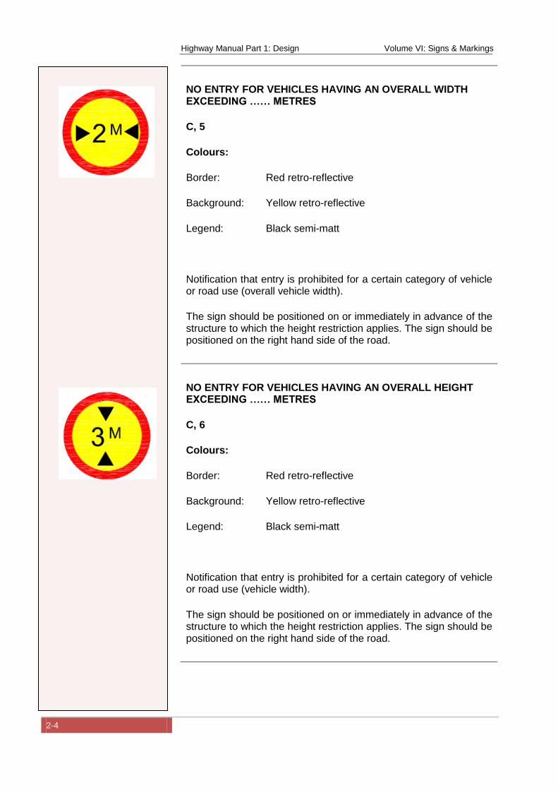
NO ENTRY FOR VEHICLES HAVING AN OVERALL WIDTH EXCEEDING …… METRES
C, 5
Colours:
Border: Red retro-reflective
Background: Yellow retro-reflective
Legend: Black semi-matt
Notification that entry is prohibited for a certain category of vehicle or road use (overall vehicle width).
The sign should be positioned on or immediately in advance of the structure to which the height restriction applies. The sign should be positioned on the right hand side of the road.
NO ENTRY FOR VEHICLES HAVING AN OVERALL HEIGHT EXCEEDING …… METRES
C, 6
Colours:
Border: Red retro-reflective
Background: Yellow retro-reflective
Legend: Black semi-matt
Notification that entry is prohibited for a certain category of vehicle or road use (vehicle width).
The sign should be positioned on or immediately in advance of the structure to which the height restriction applies. The sign should be positioned on the right hand side of the road.
Highway Manual Part 1: Design Volume VI: Signs & Markings
2-5
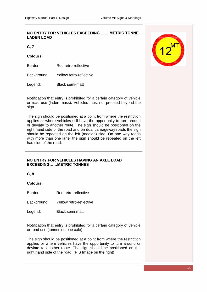
NO ENTRY FOR VEHICLES EXCEEDING …… METRIC TONNE LADEN LOAD
C, 7
Colours:
Border: Red retro-reflective
Background: Yellow retro-reflective
Legend: Black semi-matt
Notification that entry is prohibited for a certain category of vehicle or road use (laden mass). Vehicles must not proceed beyond the sign.
The sign should be positioned at a point from where the restriction applies or where vehicles still have the opportunity to turn around or deviate to another route. The sign should be positioned on the right hand side of the road and on dual carriageway roads the sign should be repeated on the left (median) side. On one way roads with more than one lane, the sign should be repeated on the left had side of the road.
NO ENTRY FOR VEHICLES HAVING AN AXLE LOAD EXCEEDING……METRIC TONNES
C, 8
Colours:
Border: Red retro-reflective
Background: Yellow retro-reflective
Legend: Black semi-matt
Notification that entry is prohibited for a certain category of vehicle or road use (tonnes on one axle).
The sign should be positioned at a point from where the restriction applies or where vehicles have the opportunity to turn around or deviate to another route. The sign should be positioned on the right hand side of the road. (P.S Image on the right)
Highway Manual Part 1: Design Volume VI: Signs & Markings
2-6
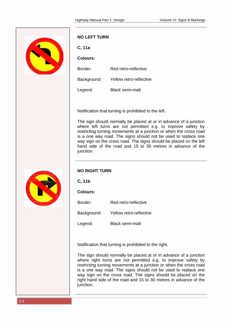
NO LEFT TURN
C, 11a
Colours:
Border: Red retro-reflective
Background: Yellow retro-reflective
Legend: Black semi-matt
Notification that turning is prohibited to the left.
The sign should normally be placed at or in advance of a junction where left turns are not permitted e.g. to improve safety by restricting turning movements at a junction or when the cross road is a one way road. The signs should not be used to replace one way sign on the cross road. The signs should be placed on the left hand side of the road and 15 to 30 metres in advance of the junction.
NO RIGHT TURN
C, 11b
Colours:
Border: Red retro-reflective
Background: Yellow retro-reflective
Legend: Black semi-matt
Notification that turning is prohibited to the right.
The sign should normally be placed at or in advance of a junction where right turns are not permitted e.g. to improve safety by restricting turning movements at a junction or when the cross road is a one way road. The signs should not be used to replace one way sign on the cross road. The signs should be placed on the right hand side of the road and 15 to 30 metres in advance of the junction.
Highway Manual Part 1: Design Volume VI: Signs & Markings
2-7
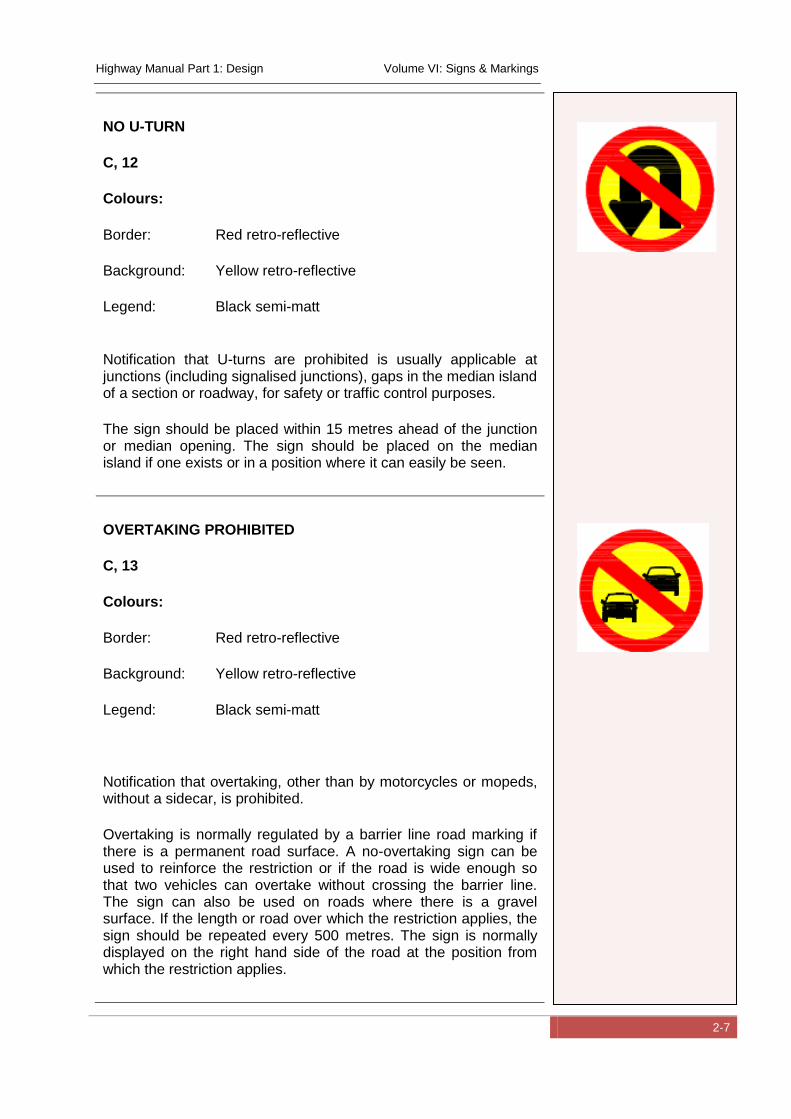
NO U-TURN
C, 12
Colours:
Border: Red retro-reflective
Background: Yellow retro-reflective
Legend: Black semi-matt
Notification that U-turns are prohibited is usually applicable at junctions (including signalised junctions), gaps in the median island of a section or roadway, for safety or traffic control purposes.
The sign should be placed within 15 metres ahead of the junction or median opening. The sign should be placed on the median island if one exists or in a position where it can easily be seen.
OVERTAKING PROHIBITED
C, 13
Colours:
Border: Red retro-reflective
Background: Yellow retro-reflective
Legend: Black semi-matt
Notification that overtaking, other than by motorcycles or mopeds, without a sidecar, is prohibited.
Overtaking is normally regulated by a barrier line road marking if there is a permanent road surface. A no-overtaking sign can be used to reinforce the restriction or if the road is wide enough so that two vehicles can overtake without crossing the barrier line. The sign can also be used on roads where there is a gravel surface. If the length or road over which the restriction applies, the sign should be repeated every 500 metres. The sign is normally displayed on the right hand side of the road at the position from which the restriction applies.
Highway Manual Part 1: Design Volume VI: Signs & Markings
2-8
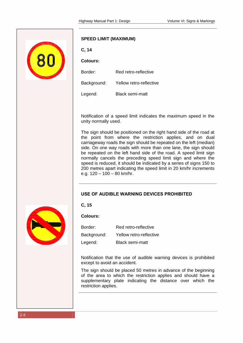
SPEED LIMIT (MAXIMUM)
C, 14
Colours:
Border: Red retro-reflective
Background: Yellow retro-reflective
Legend: Black semi-matt
Notification of a speed limit indicates the maximum speed in the unity normally used.
The sign should be positioned on the right hand side of the road at the point from where the restriction applies, and on dual carriageway roads the sign should be repeated on the left (median) side. On one way roads with more than one lane, the sign should be repeated on the left hand side of the road. A speed limit sign normally cancels the preceding speed limit sign and where the speed is reduced, it should be indicated by a series of signs 150 to 200 metres apart indicating the speed limit in 20 km/hr increments e.g. 120 – 100 – 80 km/hr.
USE OF AUDIBLE WARNING DEVICES PROHIBITED
C, 15
Colours:
Border: Red retro-reflective
Background: Yellow retro-reflective
Legend: Black semi-matt
Notification that the use of audible warning devices is prohibited except to avoid an accident.
The sign should be placed 50 metres in advance of the beginning of the area to which the restriction applies and should have a supplementary plate indicating the distance over which the restriction applies.
Highway Manual Part 1: Design Volume VI: Signs & Markings
2-9
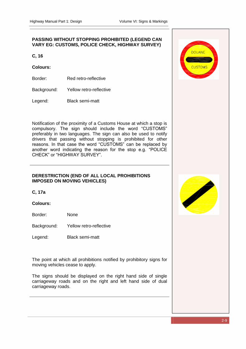
PASSING WITHOUT STOPPING PROHIBITED (LEGEND CAN VARY EG: CUSTOMS, POLICE CHECK, HIGHWAY SURVEY)
C, 16
Colours:
Border: Red retro-reflective
Background: Yellow retro-reflective
Legend: Black semi-matt
Notification of the proximity of a Customs House at which a stop is compulsory. The sign should include the word “CUSTOMS” preferably in two languages. The sign can also be used to notify drivers that passing without stopping is prohibited for other reasons. In that case the word “CUSTOMS” can be replaced by another word indicating the reason for the stop e.g. “POLICE CHECK” or “HIGHWAY SURVEY”.
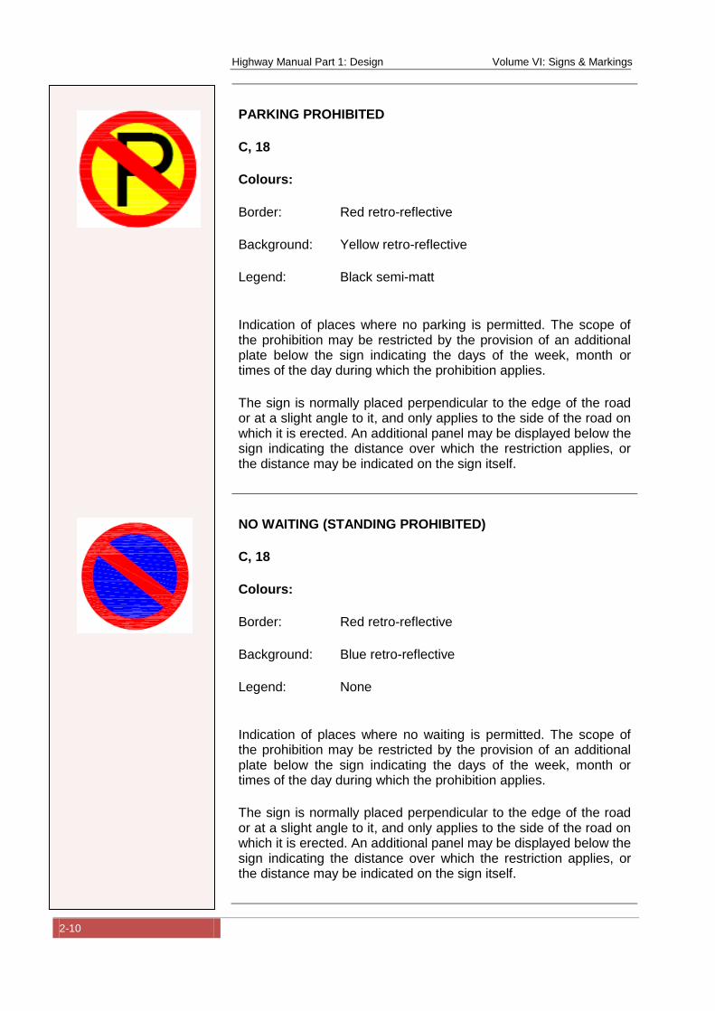
DERESTRICTION (END OF ALL LOCAL PROHIBITIONS IMPOSED ON MOVING VEHICLES)
C, 17a
Colours:
Border: None
Background: Yellow retro-reflective
Legend: Black semi-matt
The point at which all prohibitions notified by prohibitory signs for moving vehicles cease to apply.
The signs should be displayed on the right hand side of single carriageway roads and on the right and left hand side of dual carriageway roads.
Highway Manual Part 1: Design Volume VI: Signs & Markings
2-10
PARKING PROHIBITED
C, 18
Colours:
Border: Red retro-reflective
Background: Yellow retro-reflective
Legend: Black semi-matt
Indication of places where no parking is permitted. The scope of the prohibition may be restricted by the provision of an additional plate below the sign indicating the days of the week, month or times of the day during which the prohibition applies.
The sign is normally placed perpendicular to the edge of the road or at a slight angle to it, and only applies to the side of the road on which it is erected. An additional panel may be displayed below the sign indicating the distance over which the restriction applies, or the distance may be indicated on the sign itself.
NO WAITING (STANDING PROHIBITED)
C, 18
Colours:
Border: Red retro-reflective
Background: Blue retro-reflective
Legend: None
Indication of places where no waiting is permitted. The scope of the prohibition may be restricted by the provision of an additional plate below the sign indicating the days of the week, month or times of the day during which the prohibition applies.
The sign is normally placed perpendicular to the edge of the road or at a slight angle to it, and only applies to the side of the road on which it is erected. An additional panel may be displayed below the sign indicating the distance over which the restriction applies, or the distance may be indicated on the sign itself.
Highway Manual Part 1: Design Volume VI: Signs & Markings
2-11
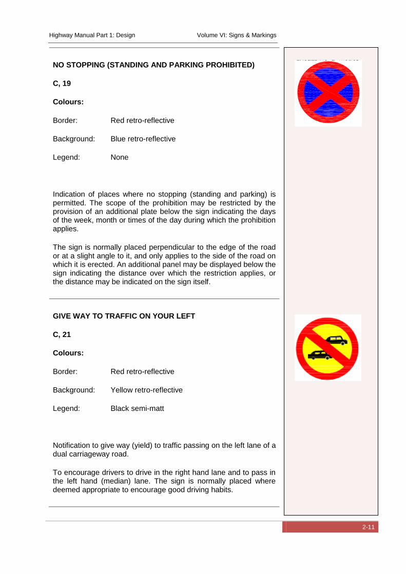
NO STOPPING (STANDING AND PARKING PROHIBITED)
C, 19
Colours:
Border: Red retro-reflective
Background: Blue retro-reflective
Legend: None
Indication of places where no stopping (standing and parking) is permitted. The scope of the prohibition may be restricted by the provision of an additional plate below the sign indicating the days of the week, month or times of the day during which the prohibition applies.
The sign is normally placed perpendicular to the edge of the road or at a slight angle to it, and only applies to the side of the road on which it is erected. An additional panel may be displayed below the sign indicating the distance over which the restriction applies, or the distance may be indicated on the sign itself.
GIVE WAY TO TRAFFIC ON YOUR LEFT
C, 21
Colours:
Border: Red retro-reflective
Background: Yellow retro-reflective
Legend: Black semi-matt
Notification to give way (yield) to traffic passing on the left lane of a dual carriageway road.
To encourage drivers to drive in the right hand lane and to pass in the left hand (median) lane. The sign is normally placed where deemed appropriate to encourage good driving habits.

Highway Manual Part 1: Design Volume VI: Signs & Markings
2-12
LITTER PROHIBITED
C, 22
Colours:
Border: Red retro-reflective
Background: Yellow retro-reflective
Legend: Black semi-matt
Notification to drivers that littering is prohibited.
The sign is normally placed where deemed appropriate to encourage good driving habits.
2.2 Regulatory Signs (Mandatory)
The Regulatory (Mandatory) signs currently adopted for use in
Nigeria are presented below in terms of the sign number (cross
referenced to the Convention on Traffic Signs (United-Nations, 2006)),
function, requirements, colour and diagrammatic representation.
DIRECTION TO BE FOLLOWED (PROCEED STRAIGHT ONLY)
D, 1a
Colours:
Border: None
Background: Blue retro-reflective
Legend: White semi-matt
The direction in which vehicles are obliged to proceed, or the only direction in which they are permitted to proceed is indicated by means of an arrow or arrows pointing in the appropriate direction or directions.
The sign should be placed on the right in advance of a junction.
Highway Manual Part 1: Design Volume VI: Signs & Markings
2-13
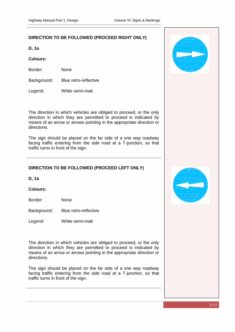
DIRECTION TO BE FOLLOWED (PROCEED RIGHT ONLY)
D, 1a
Colours:
Border: None
Background: Blue retro-reflective
Legend: White semi-matt
The direction in which vehicles are obliged to proceed, or the only direction in which they are permitted to proceed is indicated by means of an arrow or arrows pointing in the appropriate direction or directions.
The sign should be placed on the far side of a one way roadway facing traffic entering from the side road at a T-junction, so that traffic turns in front of the sign.
DIRECTION TO BE FOLLOWED (PROCEED LEFT ONLY)
D, 1a
Colours:
Border: None
Background: Blue retro-reflective
Legend: White semi-matt
The direction in which vehicles are obliged to proceed, or the only direction in which they are permitted to proceed is indicated by means of an arrow or arrows pointing in the appropriate direction or directions.
The sign should be placed on the far side of a one way roadway facing traffic entering from the side road at a T-junction, so that traffic turns in front of the sign.
Highway Manual Part 1: Design Volume VI: Signs & Markings
2-14
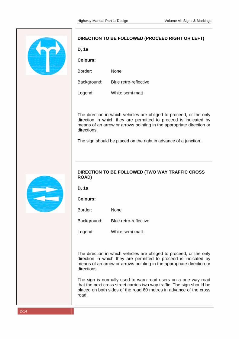
DIRECTION TO BE FOLLOWED (PROCEED RIGHT OR LEFT)
D, 1a
Colours:
Border: None
Background: Blue retro-reflective
Legend: White semi-matt
The direction in which vehicles are obliged to proceed, or the only direction in which they are permitted to proceed is indicated by means of an arrow or arrows pointing in the appropriate direction or directions.
The sign should be placed on the right in advance of a junction.
DIRECTION TO BE FOLLOWED (TWO WAY TRAFFIC CROSS ROAD)
D, 1a
Colours:
Border: None
Background: Blue retro-reflective
Legend: White semi-matt
The direction in which vehicles are obliged to proceed, or the only direction in which they are permitted to proceed is indicated by means of an arrow or arrows pointing in the appropriate direction or directions.
The sign is normally used to warn road users on a one way road that the next cross street carries two way traffic. The sign should be placed on both sides of the road 60 metres in advance of the cross road.
Highway Manual Part 1: Design Volume VI: Signs & Markings
2-15
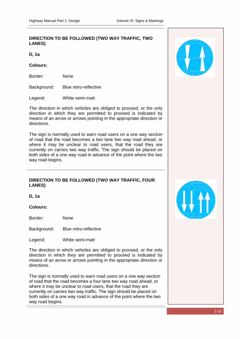
DIRECTION TO BE FOLLOWED (TWO WAY TRAFFIC, TWO LANES)
D, 1a
Colours:
Border: None
Background: Blue retro-reflective
Legend: White semi-matt The direction in which vehicles are obliged to proceed, or the only direction in which they are permitted to proceed is indicated by means of an arrow or arrows pointing in the appropriate direction or directions.
The sign is normally used to warn road users on a one way section of road that the road becomes a two lane two way road ahead, or where it may be unclear to road users, that the road they are currently on carries two way traffic. The sign should be placed on both sides of a one way road in advance of the point where the two way road begins.
DIRECTION TO BE FOLLOWED (TWO WAY TRAFFIC, FOUR LANES)
D, 1a
Colours:
Border: None
Background: Blue retro-reflective
Legend: White semi-matt The direction in which vehicles are obliged to proceed, or the only direction in which they are permitted to proceed is indicated by means of an arrow or arrows pointing in the appropriate direction or directions.
The sign is normally used to warn road users on a one way section of road that the road becomes a four lane two way road ahead, or where it may be unclear to road users, that the road they are currently on carries two way traffic. The sign should be placed on both sides of a one way road in advance of the point where the two way road begins.
Highway Manual Part 1: Design Volume VI: Signs & Markings
2-16
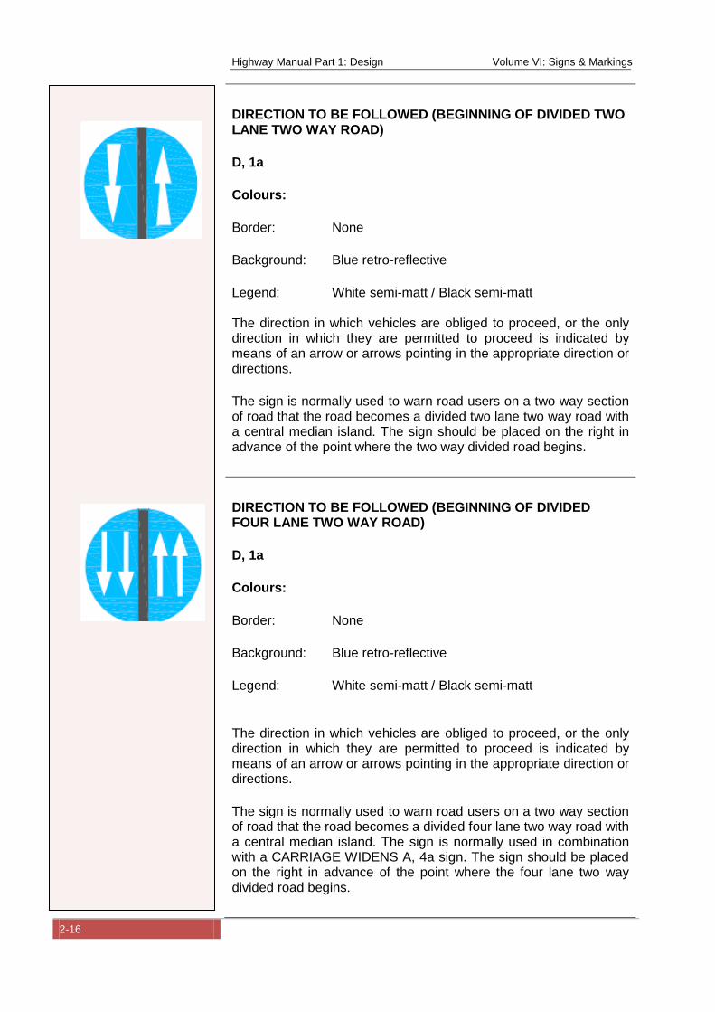
DIRECTION TO BE FOLLOWED (BEGINNING OF DIVIDED TWO LANE TWO WAY ROAD)
D, 1a
Colours:
Border: None
Background: Blue retro-reflective
Legend: White semi-matt / Black semi-matt The direction in which vehicles are obliged to proceed, or the only direction in which they are permitted to proceed is indicated by means of an arrow or arrows pointing in the appropriate direction or directions.
The sign is normally used to warn road users on a two way section of road that the road becomes a divided two lane two way road with a central median island. The sign should be placed on the right in advance of the point where the two way divided road begins.
DIRECTION TO BE FOLLOWED (BEGINNING OF DIVIDED FOUR LANE TWO WAY ROAD)
D, 1a
Colours:
Border: None
Background: Blue retro-reflective
Legend: White semi-matt / Black semi-matt
The direction in which vehicles are obliged to proceed, or the only direction in which they are permitted to proceed is indicated by means of an arrow or arrows pointing in the appropriate direction or directions.
The sign is normally used to warn road users on a two way section of road that the road becomes a divided four lane two way road with a central median island. The sign is normally used in combination with a CARRIAGE WIDENS A, 4a sign. The sign should be placed on the right in advance of the point where the four lane two way divided road begins.
Highway Manual Part 1: Design Volume VI: Signs & Markings
2-17
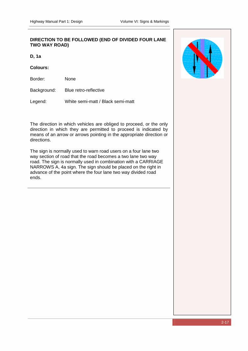
DIRECTION TO BE FOLLOWED (END OF DIVIDED FOUR LANE TWO WAY ROAD)
D, 1a
Colours:
Border: None
Background: Blue retro-reflective
Legend: White semi-matt / Black semi-matt
The direction in which vehicles are obliged to proceed, or the only direction in which they are permitted to proceed is indicated by means of an arrow or arrows pointing in the appropriate direction or directions.
The sign is normally used to warn road users on a four lane two way section of road that the road becomes a two lane two way road. The sign is normally used in combination with a CARRIAGE NARROWS A, 4a sign. The sign should be placed on the right in advance of the point where the four lane two way divided road ends.
Highway Manual Part 1: Design Volume VI: Signs & Markings
2-18
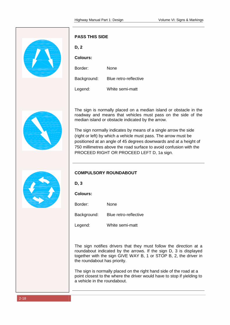
PASS THIS SIDE
D, 2
Colours:
Border: None
Background: Blue retro-reflective
Legend: White semi-matt
The sign is normally placed on a median island or obstacle in the roadway and means that vehicles must pass on the side of the median island or obstacle indicated by the arrow.
The sign normally indicates by means of a single arrow the side
(right or left) by which a vehicle must pass. The arrow must be
positioned at an angle of 45 degrees downwards and at a height of
750 millimetres above the road surface to avoid confusion with the
PROCEED RIGHT OR PROCEED LEFT D, 1a sign.
COMPULSORY ROUNDABOUT
D, 3
Colours:
Border: None
Background: Blue retro-reflective
Legend: White semi-matt
The sign notifies drivers that they must follow the direction at a roundabout indicated by the arrows. If the sign D, 3 is displayed together with the sign GIVE WAY B, 1 or STOP B, 2, the driver in the roundabout has priority.
The sign is normally placed on the right hand side of the road at a point closest to the where the driver would have to stop if yielding to a vehicle in the roundabout.
Highway Manual Part 1: Design Volume VI: Signs & Markings
2-19
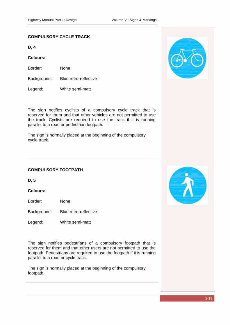
COMPULSORY CYCLE TRACK
D, 4
Colours:
Border: None
Background: Blue retro-reflective
Legend: White semi-matt
The sign notifies cyclists of a compulsory cycle track that is reserved for them and that other vehicles are not permitted to use the track. Cyclists are required to use the track if it is running parallel to a road or pedestrian footpath.
The sign is normally placed at the beginning of the compulsory cycle track.
COMPULSORY FOOTPATH
D, 5
Colours:
Border: None
Background: Blue retro-reflective
Legend: White semi-matt
The sign notifies pedestrians of a compulsory footpath that is reserved for them and that other users are not permitted to use the footpath. Pedestrians are required to use the footpath if it is running parallel to a road or cycle track.
The sign is normally placed at the beginning of the compulsory footpath.
Highway Manual Part 1: Design Volume VI: Signs & Markings
2-20
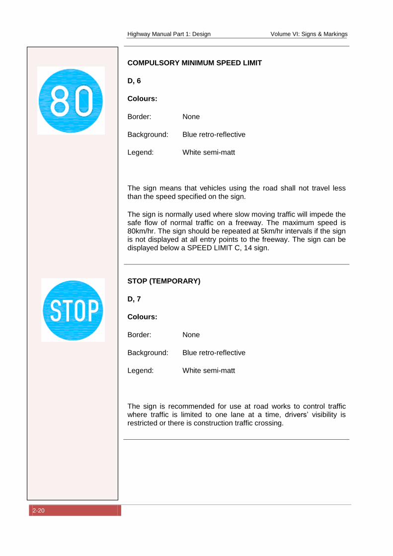
COMPULSORY MINIMUM SPEED LIMIT
D, 6
Colours:
Border: None
Background: Blue retro-reflective
Legend: White semi-matt
The sign means that vehicles using the road shall not travel less than the speed specified on the sign.
The sign is normally used where slow moving traffic will impede the safe flow of normal traffic on a freeway. The maximum speed is 80km/hr. The sign should be repeated at 5km/hr intervals if the sign is not displayed at all entry points to the freeway. The sign can be displayed below a SPEED LIMIT C, 14 sign.
STOP (TEMPORARY)
D, 7
Colours:
Border: None
Background: Blue retro-reflective
Legend: White semi-matt
The sign is recommended for use at road works to control traffic where traffic is limited to one lane at a time, drivers’ visibility is restricted or there is construction traffic crossing.
Highway Manual Part 1: Design Volume VI: Signs & Markings
2-21
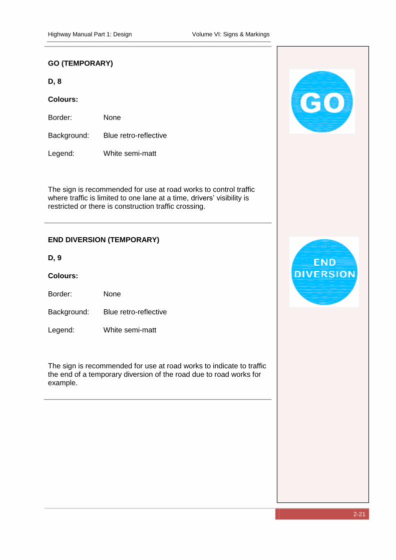
GO (TEMPORARY)
D, 8
Colours:
Border: None
Background: Blue retro-reflective
Legend: White semi-matt
The sign is recommended for use at road works to control traffic where traffic is limited to one lane at a time, drivers’ visibility is restricted or there is construction traffic crossing.
END DIVERSION (TEMPORARY)
D, 9
Colours:
Border: None
Background: Blue retro-reflective
Legend: White semi-matt
The sign is recommended for use at road works to indicate to traffic the end of a temporary diversion of the road due to road works for example.
Highway Manual Part 1: Design Volume VI: Signs & Markings
2-22
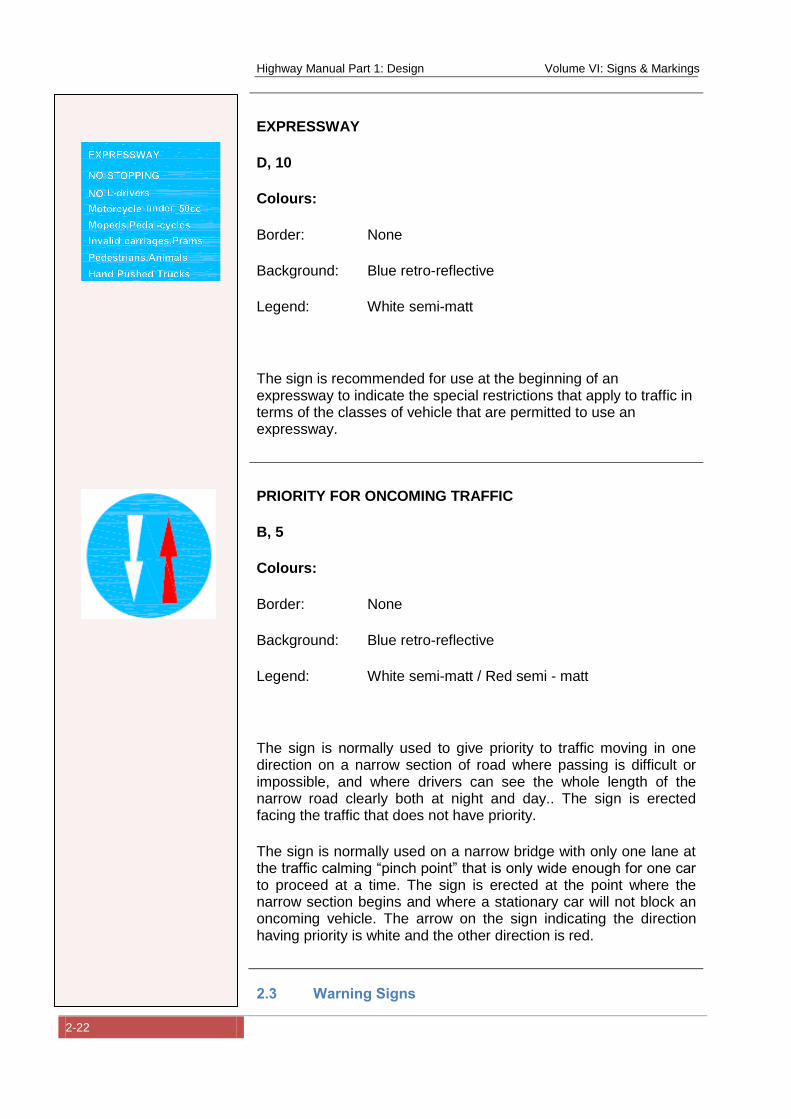
EXPRESSWAY
D, 10
Colours:
Border: None
Background: Blue retro-reflective
Legend: White semi-matt
The sign is recommended for use at the beginning of an expressway to indicate the special restrictions that apply to traffic in terms of the classes of vehicle that are permitted to use an expressway.
PRIORITY FOR ONCOMING TRAFFIC
B, 5
Colours:
Border: None
Background: Blue retro-reflective
Legend: White semi-matt / Red semi - matt
The sign is normally used to give priority to traffic moving in one direction on a narrow section of road where passing is difficult or impossible, and where drivers can see the whole length of the narrow road clearly both at night and day.. The sign is erected facing the traffic that does not have priority.
The sign is normally used on a narrow bridge with only one lane at the traffic calming “pinch point” that is only wide enough for one car to proceed at a time. The sign is erected at the point where the narrow section begins and where a stationary car will not block an oncoming vehicle. The arrow on the sign indicating the direction having priority is white and the other direction is red.
2.3 Warning Signs
Highway Manual Part 1: Design Volume VI: Signs & Markings
2-23
The Warning signs currently adopted for use in Nigeria are
presented below in terms of the sign number (cross referenced to
the Convention on Traffic Signs (United-Nations, 2006)), function,
requirements, colour and diagrammatic representation.
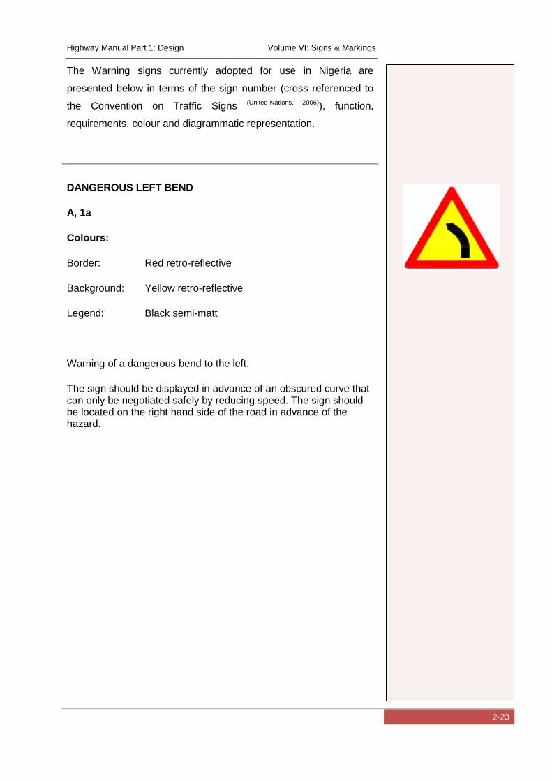
DANGEROUS LEFT BEND
A, 1a
Colours:
Border: Red retro-reflective
Background: Yellow retro-reflective
Legend: Black semi-matt
Warning of a dangerous bend to the left.
The sign should be displayed in advance of an obscured curve that can only be negotiated safely by reducing speed. The sign should be located on the right hand side of the road in advance of the hazard.
Highway Manual Part 1: Design Volume VI: Signs & Markings
2-24
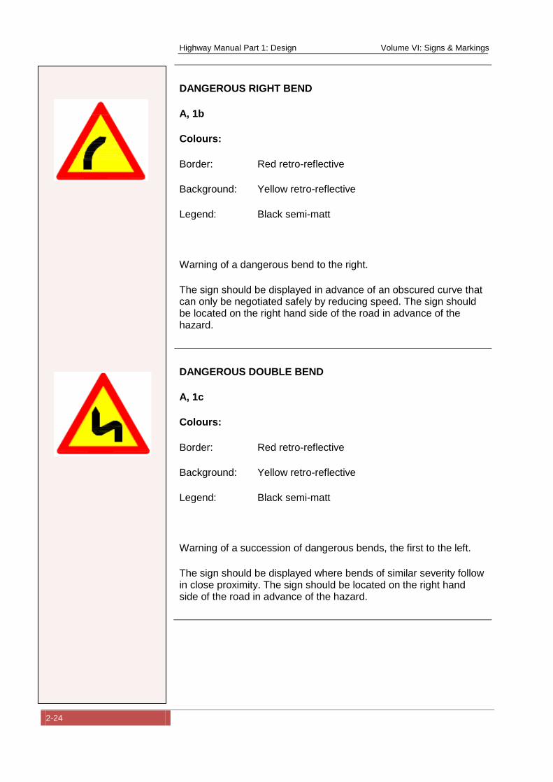
DANGEROUS RIGHT BEND
A, 1b
Colours:
Border: Red retro-reflective
Background: Yellow retro-reflective
Legend: Black semi-matt
Warning of a dangerous bend to the right.
The sign should be displayed in advance of an obscured curve that can only be negotiated safely by reducing speed. The sign should be located on the right hand side of the road in advance of the hazard.
DANGEROUS DOUBLE BEND
A, 1c
Colours:
Border: Red retro-reflective
Background: Yellow retro-reflective
Legend: Black semi-matt
Warning of a succession of dangerous bends, the first to the left.
The sign should be displayed where bends of similar severity follow in close proximity. The sign should be located on the right hand side of the road in advance of the hazard.
Highway Manual Part 1: Design Volume VI: Signs & Markings
2-25
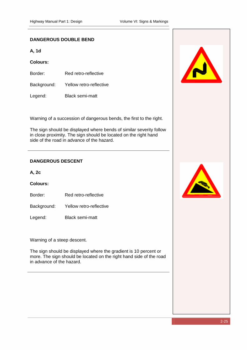
DANGEROUS DOUBLE BEND
A, 1d
Colours:
Border: Red retro-reflective
Background: Yellow retro-reflective
Legend: Black semi-matt
Warning of a succession of dangerous bends, the first to the right.
The sign should be displayed where bends of similar severity follow in close proximity. The sign should be located on the right hand side of the road in advance of the hazard.
DANGEROUS DESCENT
A, 2c
Colours:
Border: Red retro-reflective
Background: Yellow retro-reflective
Legend: Black semi-matt
Warning of a steep descent.
The sign should be displayed where the gradient is 10 percent or more. The sign should be located on the right hand side of the road in advance of the hazard.
Highway Manual Part 1: Design Volume VI: Signs & Markings
2-26
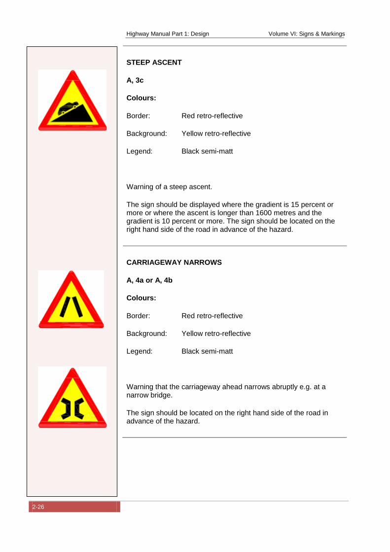
STEEP ASCENT
A, 3c
Colours:
Border: Red retro-reflective
Background: Yellow retro-reflective
Legend: Black semi-matt
Warning of a steep ascent.
The sign should be displayed where the gradient is 15 percent or more or where the ascent is longer than 1600 metres and the gradient is 10 percent or more. The sign should be located on the right hand side of the road in advance of the hazard.
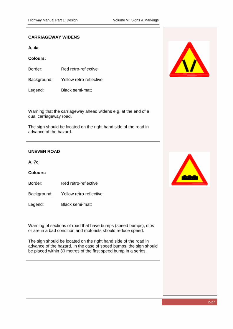
CARRIAGEWAY NARROWS
A, 4a or A, 4b
Colours:
Border: Red retro-reflective
Background: Yellow retro-reflective
Legend: Black semi-matt
Warning that the carriageway ahead narrows abruptly e.g. at a narrow bridge.
The sign should be located on the right hand side of the road in advance of the hazard.
Highway Manual Part 1: Design Volume VI: Signs & Markings
2-27
CARRIAGEWAY WIDENS
A, 4a
Colours:
Border: Red retro-reflective
Background: Yellow retro-reflective
Legend: Black semi-matt
Warning that the carriageway ahead widens e.g. at the end of a dual carriageway road.
The sign should be located on the right hand side of the road in advance of the hazard.
UNEVEN ROAD
A, 7c
Colours:
Border: Red retro-reflective
Background: Yellow retro-reflective
Legend: Black semi-matt
Warning of sections of road that have bumps (speed bumps), dips or are in a bad condition and motorists should reduce speed.
The sign should be located on the right hand side of the road in advance of the hazard. In the case of speed bumps, the sign should be placed within 30 metres of the first speed bump in a series.

Highway Manual Part 1: Design Volume VI: Signs & Markings
2-28
SLIPPERY ROAD
A, 9
Colours:
Border: Red retro-reflective
Background: Yellow retro-reflective
Legend: Black semi-matt
Warning of sections of road that may be particularly slippery and motorists should reduce speed.
The sign should be located on the right hand side of the road in advance of the hazard.
LOOSE GRAVEL
A, 10a
Colours:
Border: Red retro-reflective
Background: Yellow retro-reflective
Legend: Black semi-matt
Warning of sections of road on which gravel may be thrown up e.g. on a gravel road, after recent road construction or due to poor road maintenance.
The sign should be located on the right hand side of the road in advance of the hazard.
Highway Manual Part 1: Design Volume VI: Signs & Markings
2-29
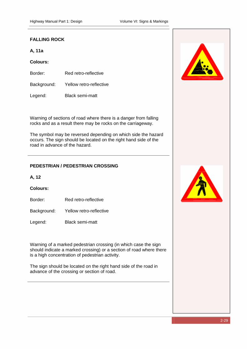
FALLING ROCK
A, 11a
Colours:
Border: Red retro-reflective
Background: Yellow retro-reflective
Legend: Black semi-matt
Warning of sections of road where there is a danger from falling rocks and as a result there may be rocks on the carriageway.
The symbol may be reversed depending on which side the hazard occurs. The sign should be located on the right hand side of the road in advance of the hazard.
PEDESTRIAN / PEDESTRIAN CROSSING
A, 12
Colours:
Border: Red retro-reflective
Background: Yellow retro-reflective
Legend: Black semi-matt
Warning of a marked pedestrian crossing (in which case the sign should indicate a marked crossing) or a section of road where there is a high concentration of pedestrian activity.
The sign should be located on the right hand side of the road in advance of the crossing or section of road.
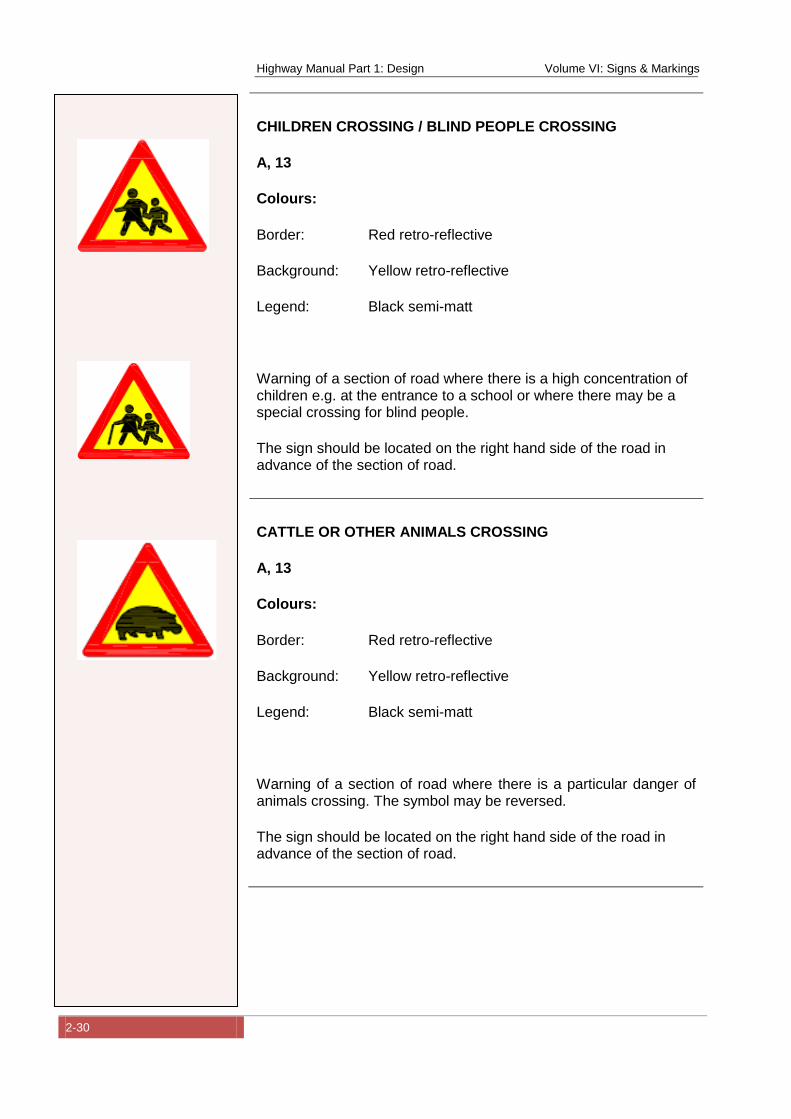
Highway Manual Part 1: Design Volume VI: Signs & Markings
2-30
CHILDREN CROSSING / BLIND PEOPLE CROSSING
A, 13
Colours:
Border: Red retro-reflective
Background: Yellow retro-reflective
Legend: Black semi-matt
Warning of a section of road where there is a high concentration of children e.g. at the entrance to a school or where there may be a special crossing for blind people.
The sign should be located on the right hand side of the road in advance of the section of road.
CATTLE OR OTHER ANIMALS CROSSING
A, 13
Colours:
Border: Red retro-reflective
Background: Yellow retro-reflective
Legend: Black semi-matt
Warning of a section of road where there is a particular danger of animals crossing. The symbol may be reversed.
The sign should be located on the right hand side of the road in advance of the section of road.
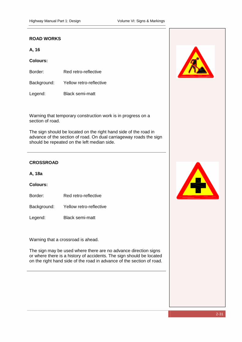
Highway Manual Part 1: Design Volume VI: Signs & Markings
2-31
ROAD WORKS
A, 16
Colours:
Border: Red retro-reflective
Background: Yellow retro-reflective
Legend: Black semi-matt
Warning that temporary construction work is in progress on a section of road.
The sign should be located on the right hand side of the road in advance of the section of road. On dual carriageway roads the sign should be repeated on the left median side.
CROSSROAD
A, 18a
Colours:
Border: Red retro-reflective
Background: Yellow retro-reflective
Legend: Black semi-matt
Warning that a crossroad is ahead.
The sign may be used where there are no advance direction signs or where there is a history of accidents. The sign should be located on the right hand side of the road in advance of the section of road.
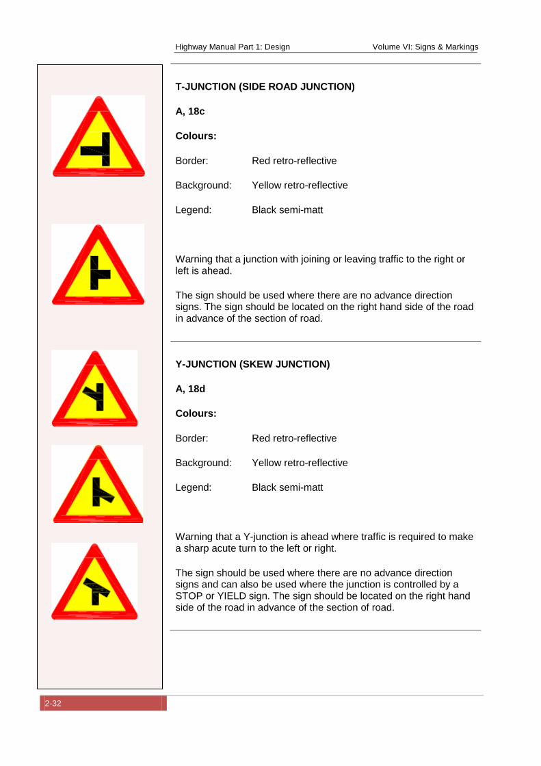
Highway Manual Part 1: Design Volume VI: Signs & Markings
2-32
T-JUNCTION (SIDE ROAD JUNCTION)
A, 18c
Colours:
Border: Red retro-reflective
Background: Yellow retro-reflective
Legend: Black semi-matt
Warning that a junction with joining or leaving traffic to the right or left is ahead.
The sign should be used where there are no advance direction signs. The sign should be located on the right hand side of the road in advance of the section of road.
Y-JUNCTION (SKEW JUNCTION)
A, 18d
Colours:
Border: Red retro-reflective
Background: Yellow retro-reflective
Legend: Black semi-matt
Warning that a Y-junction is ahead where traffic is required to make a sharp acute turn to the left or right.
The sign should be used where there are no advance direction signs and can also be used where the junction is controlled by a STOP or YIELD sign. The sign should be located on the right hand side of the road in advance of the section of road.
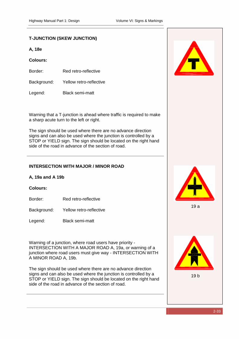
Highway Manual Part 1: Design Volume VI: Signs & Markings
2-33
T-JUNCTION (SKEW JUNCTION)
A, 18e
Colours:
Border: Red retro-reflective
Background: Yellow retro-reflective
Legend: Black semi-matt
Warning that a T-junction is ahead where traffic is required to make a sharp acute turn to the left or right.
The sign should be used where there are no advance direction signs and can also be used where the junction is controlled by a STOP or YIELD sign. The sign should be located on the right hand side of the road in advance of the section of road.
INTERSECTION WITH MAJOR / MINOR ROAD
A, 19a and A 19b
Colours:
Border: Red retro-reflective
Background: Yellow retro-reflective
Legend: Black semi-matt
Warning of a junction, where road users have priority - INTERSECTION WITH A MAJOR ROAD A, 19a, or warning of a junction where road users must give way - INTERSECTION WITH A MINOR ROAD A, 19b.
The sign should be used where there are no advance direction signs and can also be used where the junction is controlled by a STOP or YIELD sign. The sign should be located on the right hand side of the road in advance of the section of road.
19 a
19 b
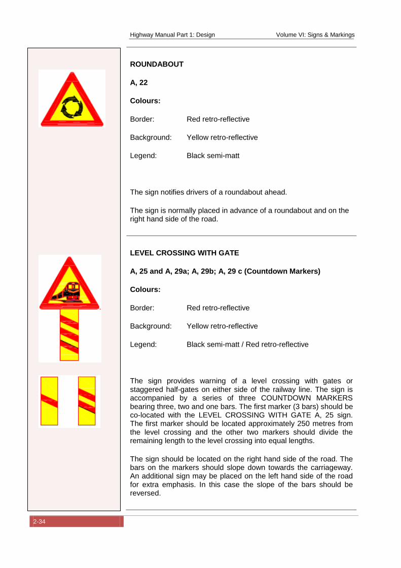
Highway Manual Part 1: Design Volume VI: Signs & Markings
2-34
ROUNDABOUT
A, 22
Colours:
Border: Red retro-reflective
Background: Yellow retro-reflective
Legend: Black semi-matt
The sign notifies drivers of a roundabout ahead.
The sign is normally placed in advance of a roundabout and on the right hand side of the road.
LEVEL CROSSING WITH GATE
A, 25 and A, 29a; A, 29b; A, 29 c (Countdown Markers)
Colours:
Border: Red retro-reflective
Background: Yellow retro-reflective
Legend: Black semi-matt / Red retro-reflective
The sign provides warning of a level crossing with gates or staggered half-gates on either side of the railway line. The sign is accompanied by a series of three COUNTDOWN MARKERS bearing three, two and one bars. The first marker (3 bars) should be co-located with the LEVEL CROSSING WITH GATE A, 25 sign. The first marker should be located approximately 250 metres from the level crossing and the other two markers should divide the remaining length to the level crossing into equal lengths.
The sign should be located on the right hand side of the road. The bars on the markers should slope down towards the carriageway. An additional sign may be placed on the left hand side of the road for extra emphasis. In this case the slope of the bars should be reversed.
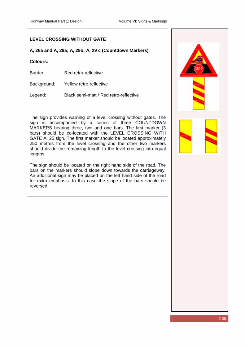
Highway Manual Part 1: Design Volume VI: Signs & Markings
2-35
LEVEL CROSSING WITHOUT GATE
A, 26a and A, 29a; A, 29b; A, 29 c (Countdown Markers)
Colours:
Border: Red retro-reflective
Background: Yellow retro-reflective
Legend: Black semi-matt / Red retro-reflective
The sign provides warning of a level crossing without gates. The sign is accompanied by a series of three COUNTDOWN MARKERS bearing three, two and one bars. The first marker (3 bars) should be co-located with the LEVEL CROSSING WITH GATE A, 25 sign. The first marker should be located approximately 250 metres from the level crossing and the other two markers should divide the remaining length to the level crossing into equal lengths.
The sign should be located on the right hand side of the road. The bars on the markers should slope down towards the carriageway. An additional sign may be placed on the left hand side of the road for extra emphasis. In this case the slope of the bars should be reversed.
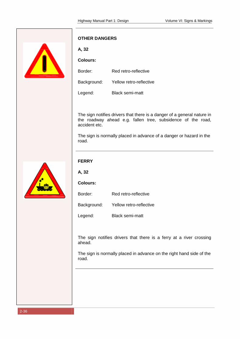
Highway Manual Part 1: Design Volume VI: Signs & Markings
2-36
OTHER DANGERS
A, 32
Colours:
Border: Red retro-reflective
Background: Yellow retro-reflective
Legend: Black semi-matt
The sign notifies drivers that there is a danger of a general nature in the roadway ahead e.g. fallen tree, subsidence of the road, accident etc.
The sign is normally placed in advance of a danger or hazard in the road.
FERRY
A, 32
Colours:
Border: Red retro-reflective
Background: Yellow retro-reflective
Legend: Black semi-matt
The sign notifies drivers that there is a ferry at a river crossing ahead.
The sign is normally placed in advance on the right hand side of the road.
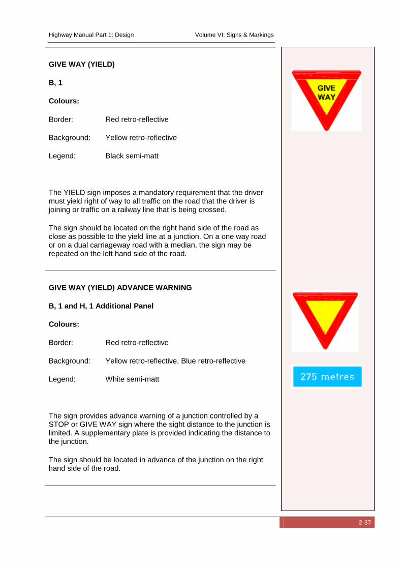
Highway Manual Part 1: Design Volume VI: Signs & Markings
2-37
GIVE WAY (YIELD)
B, 1
Colours:
Border: Red retro-reflective
Background: Yellow retro-reflective
Legend: Black semi-matt
The YIELD sign imposes a mandatory requirement that the driver must yield right of way to all traffic on the road that the driver is joining or traffic on a railway line that is being crossed.
The sign should be located on the right hand side of the road as close as possible to the yield line at a junction. On a one way road or on a dual carriageway road with a median, the sign may be repeated on the left hand side of the road.
GIVE WAY (YIELD) ADVANCE WARNING
B, 1 and H, 1 Additional Panel
Colours:
Border: Red retro-reflective
Background: Yellow retro-reflective, Blue retro-reflective
Legend: White semi-matt
The sign provides advance warning of a junction controlled by a STOP or GIVE WAY sign where the sight distance to the junction is limited. A supplementary plate is provided indicating the distance to the junction.
The sign should be located in advance of the junction on the right hand side of the road.
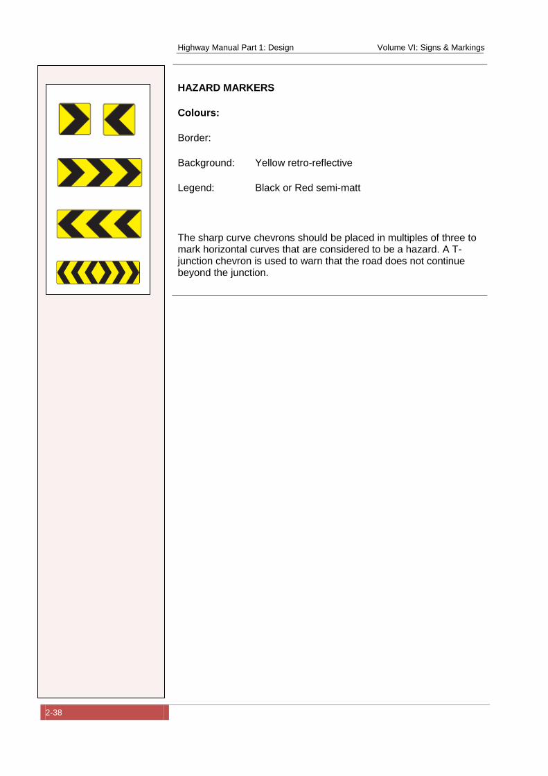
Highway Manual Part 1: Design Volume VI: Signs & Markings
2-38
HAZARD MARKERS
Colours:
Border:
Background: Yellow retro-reflective
Legend: Black or Red semi-matt
The sharp curve chevrons should be placed in multiples of three to mark horizontal curves that are considered to be a hazard. A T-junction chevron is used to warn that the road does not continue beyond the junction.
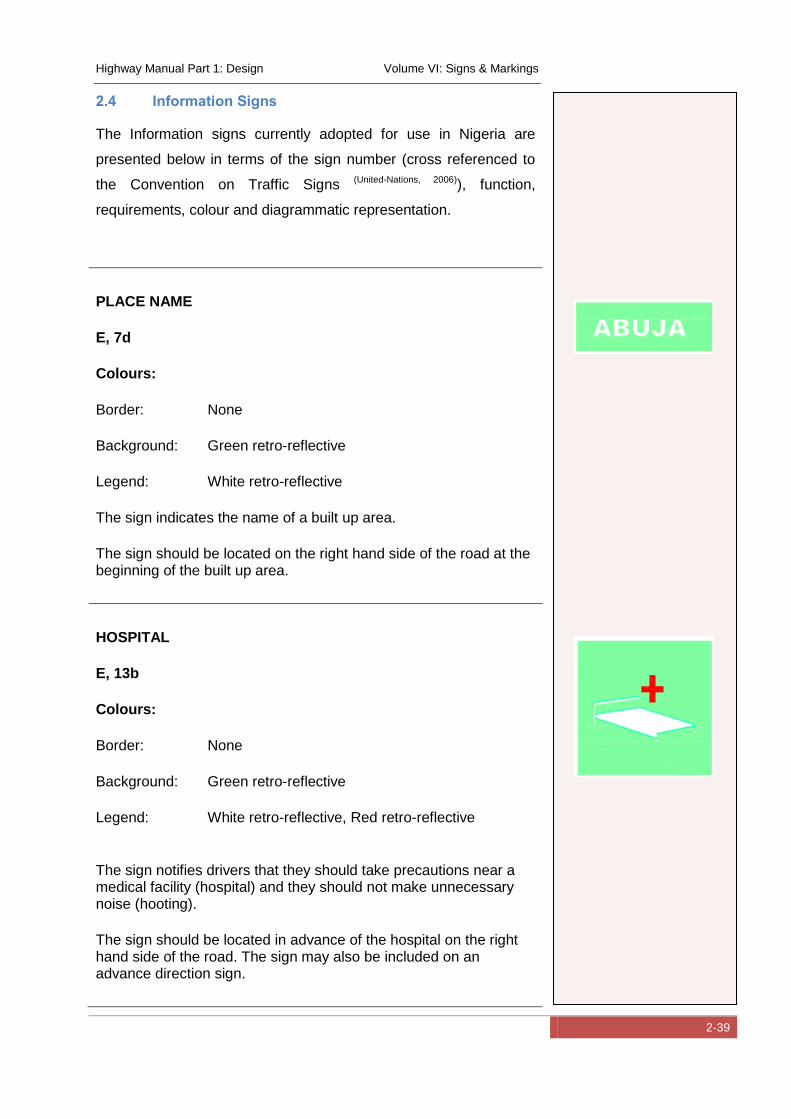
Highway Manual Part 1: Design Volume VI: Signs & Markings
2-39
2.4 Information Signs
The Information signs currently adopted for use in Nigeria are
presented below in terms of the sign number (cross referenced to
the Convention on Traffic Signs (United-Nations, 2006)), function,
requirements, colour and diagrammatic representation.
PLACE NAME
E, 7d
Colours:
Border: None
Background: Green retro-reflective
Legend: White retro-reflective
The sign indicates the name of a built up area.
The sign should be located on the right hand side of the road at the beginning of the built up area.
HOSPITAL
E, 13b
Colours:
Border: None
Background: Green retro-reflective
Legend: White retro-reflective, Red retro-reflective
The sign notifies drivers that they should take precautions near a medical facility (hospital) and they should not make unnecessary noise (hooting).
The sign should be located in advance of the hospital on the right hand side of the road. The sign may also be included on an advance direction sign.
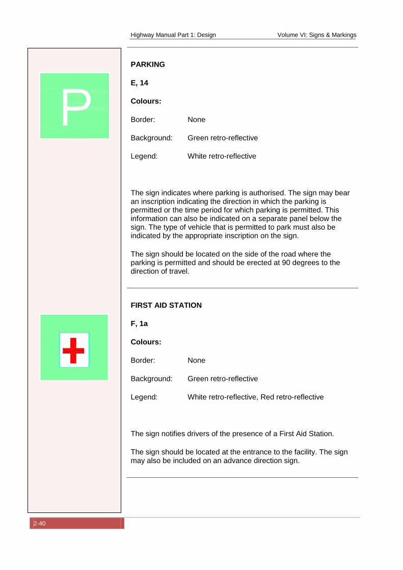
Highway Manual Part 1: Design Volume VI: Signs & Markings
2-40
PARKING
E, 14
Colours:
Border: None
Background: Green retro-reflective
Legend: White retro-reflective
The sign indicates where parking is authorised. The sign may bear an inscription indicating the direction in which the parking is permitted or the time period for which parking is permitted. This information can also be indicated on a separate panel below the sign. The type of vehicle that is permitted to park must also be indicated by the appropriate inscription on the sign.
The sign should be located on the side of the road where the parking is permitted and should be erected at 90 degrees to the direction of travel.
FIRST AID STATION
F, 1a
Colours:
Border: None
Background: Green retro-reflective
Legend: White retro-reflective, Red retro-reflective
The sign notifies drivers of the presence of a First Aid Station.
The sign should be located at the entrance to the facility. The sign may also be included on an advance direction sign.
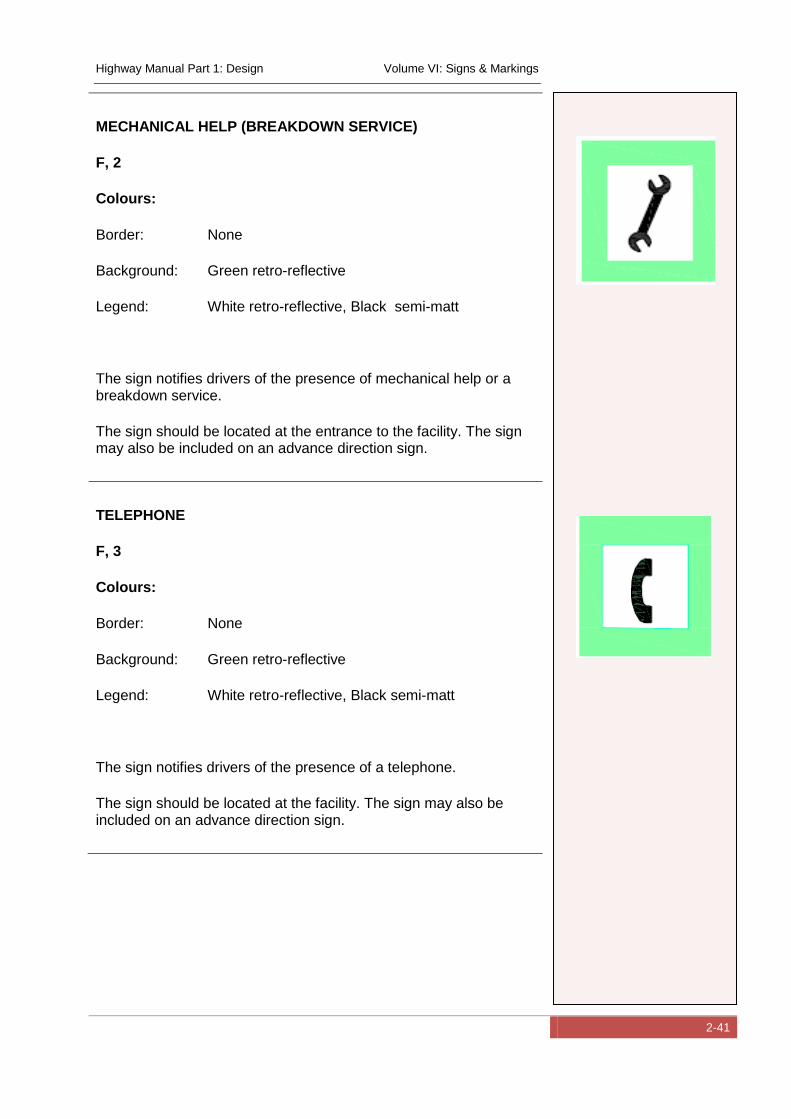
Highway Manual Part 1: Design Volume VI: Signs & Markings
2-41
MECHANICAL HELP (BREAKDOWN SERVICE)
F, 2
Colours:
Border: None
Background: Green retro-reflective
Legend: White retro-reflective, Black semi-matt
The sign notifies drivers of the presence of mechanical help or a breakdown service.
The sign should be located at the entrance to the facility. The sign may also be included on an advance direction sign.
TELEPHONE
F, 3
Colours:
Border: None
Background: Green retro-reflective
Legend: White retro-reflective, Black semi-matt
The sign notifies drivers of the presence of a telephone.
The sign should be located at the facility. The sign may also be included on an advance direction sign.
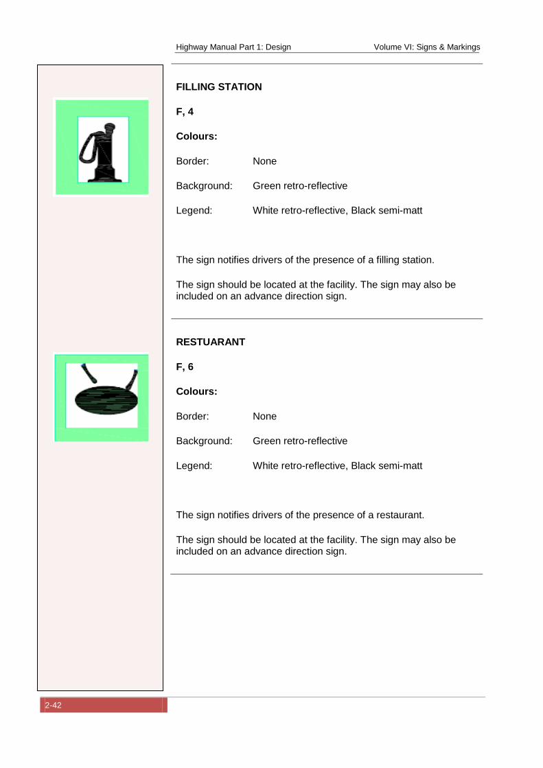
Highway Manual Part 1: Design Volume VI: Signs & Markings
2-42
FILLING STATION
F, 4
Colours:
Border: None
Background: Green retro-reflective
Legend: White retro-reflective, Black semi-matt
The sign notifies drivers of the presence of a filling station.
The sign should be located at the facility. The sign may also be included on an advance direction sign.
RESTUARANT
F, 6
Colours:
Border: None
Background: Green retro-reflective
Legend: White retro-reflective, Black semi-matt
The sign notifies drivers of the presence of a restaurant.
The sign should be located at the facility. The sign may also be included on an advance direction sign.
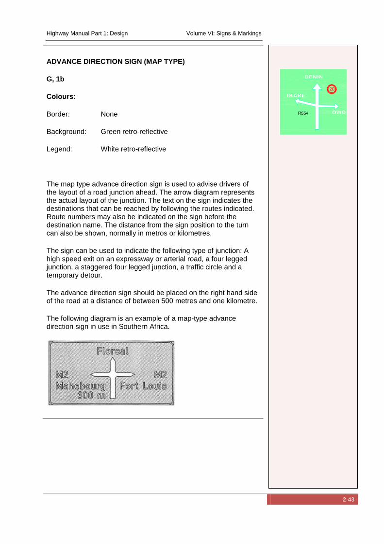
Highway Manual Part 1: Design Volume VI: Signs & Markings
2-43
ADVANCE DIRECTION SIGN (MAP TYPE)
G, 1b
Colours:
Border: None
Background: Green retro-reflective
Legend: White retro-reflective
The map type advance direction sign is used to advise drivers of the layout of a road junction ahead. The arrow diagram represents the actual layout of the junction. The text on the sign indicates the destinations that can be reached by following the routes indicated. Route numbers may also be indicated on the sign before the destination name. The distance from the sign position to the turn can also be shown, normally in metros or kilometres.
The sign can be used to indicate the following type of junction: A high speed exit on an expressway or arterial road, a four legged junction, a staggered four legged junction, a traffic circle and a temporary detour.
The advance direction sign should be placed on the right hand side of the road at a distance of between 500 metres and one kilometre.
The following diagram is an example of a map-type advance direction sign in use in Southern Africa.
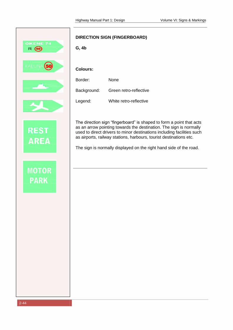
Highway Manual Part 1: Design Volume VI: Signs & Markings
2-44
DIRECTION SIGN (FINGERBOARD)
G, 4b
Colours:
Border: None
Background: Green retro-reflective
Legend: White retro-reflective
The direction sign “fingerboard” is shaped to form a point that acts as an arrow pointing towards the destination. The sign is normally used to direct drivers to minor destinations including facilities such as airports, railway stations, harbours, tourist destinations etc.
The sign is normally displayed on the right hand side of the road.
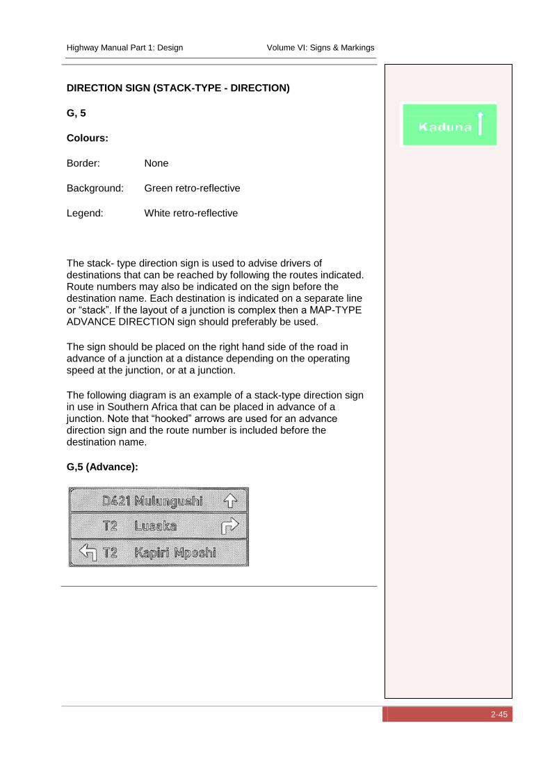
Highway Manual Part 1: Design Volume VI: Signs & Markings
2-45
DIRECTION SIGN (STACK-TYPE - DIRECTION)
G, 5
Colours:
Border: None
Background: Green retro-reflective
Legend: White retro-reflective
The stack- type direction sign is used to advise drivers of destinations that can be reached by following the routes indicated. Route numbers may also be indicated on the sign before the destination name. Each destination is indicated on a separate line or “stack”. If the layout of a junction is complex then a MAP-TYPE ADVANCE DIRECTION sign should preferably be used.
The sign should be placed on the right hand side of the road in advance of a junction at a distance depending on the operating speed at the junction, or at a junction.
The following diagram is an example of a stack-type direction sign in use in Southern Africa that can be placed in advance of a junction. Note that “hooked” arrows are used for an advance direction sign and the route number is included before the destination name.
G,5 (Advance):
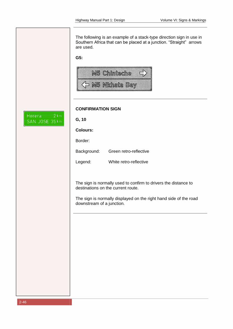
Highway Manual Part 1: Design Volume VI: Signs & Markings
2-46
The following is an example of a stack-type direction sign in use in Southern Africa that can be placed at a junction. “Straight” arrows are used.
G5:
CONFIRMATION SIGN
G, 10
Colours:
Border:
Background: Green retro-reflective
Legend: White retro-reflective
The sign is normally used to confirm to drivers the distance to destinations on the current route.
The sign is normally displayed on the right hand side of the road downstream of a junction.
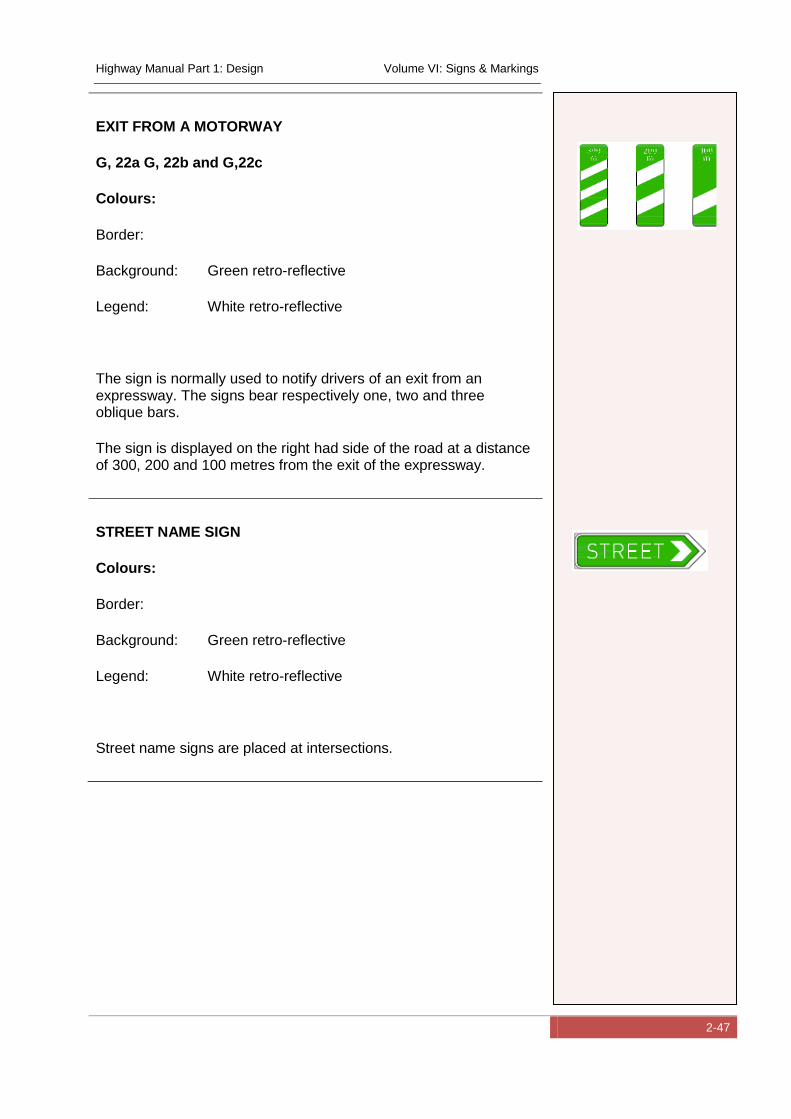
Highway Manual Part 1: Design Volume VI: Signs & Markings
2-47
EXIT FROM A MOTORWAY
G, 22a G, 22b and G,22c
Colours:
Border:
Background: Green retro-reflective
Legend: White retro-reflective
The sign is normally used to notify drivers of an exit from an expressway. The signs bear respectively one, two and three oblique bars.
The sign is displayed on the right had side of the road at a distance of 300, 200 and 100 metres from the exit of the expressway.
STREET NAME SIGN
Colours:
Border:
Background: Green retro-reflective
Legend: White retro-reflective
Street name signs are placed at intersections.
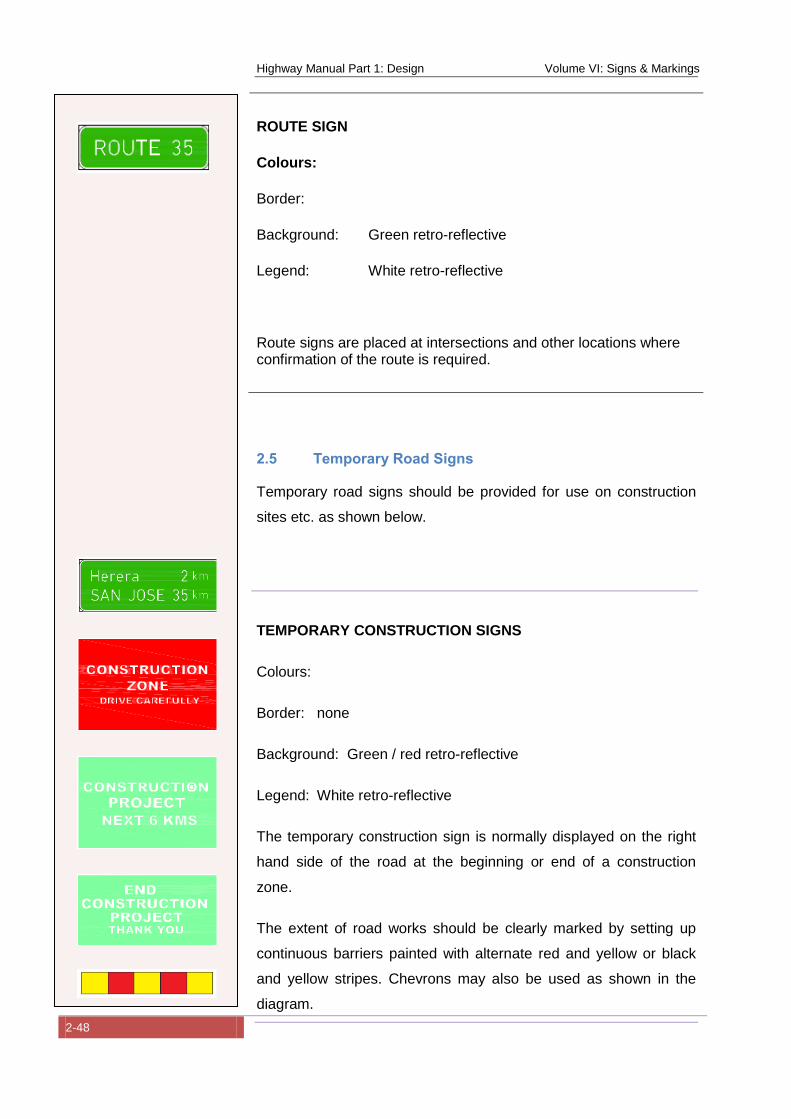
Highway Manual Part 1: Design Volume VI: Signs & Markings
2-48
ROUTE SIGN
Colours:
Border:
Background: Green retro-reflective
Legend: White retro-reflective
Route signs are placed at intersections and other locations where confirmation of the route is required.
2.5 Temporary Road Signs
Temporary road signs should be provided for use on construction
sites etc. as shown below.
TEMPORARY CONSTRUCTION SIGNS
Colours:
Border: none
Background: Green / red retro-reflective
Legend: White retro-reflective
The temporary construction sign is normally displayed on the right
hand side of the road at the beginning or end of a construction
zone.
The extent of road works should be clearly marked by setting up
continuous barriers painted with alternate red and yellow or black
and yellow stripes. Chevrons may also be used as shown in the
diagram.
Highway Manual Part 1: Design Volume VI: Signs & Markings
3-1
3 Road Markings
3.1 Introduction
Road markings make a vital contribution to safety by clearly
defining the path to be followed through hazards, by separating
conflicting movement and by directing the road edge on unlit roads
at night. They can also improve junction capacity and make best
use of space.
Road markings are used to regulate traffic, to warn or guide road-
users. They may be used either alone or in conjunction with other
signs or signals to emphasize or clarify their meaning. Road
markings are defined as markings applied to or attached to the road
surface as well as objects embedded in the road surface. The
following are typical types of road markings:
Longitudinal markings
Transverse markings
Arrow markings
Oblique parallel lines (painted islands)
Word markings
Standing and parking regulations
Markings on the carriageway or on adjacent structures
Road markings are usually classified as follows:
Regulatory markings
Warning markings
Guidance markings
Other delineation devices
The above is discussed in more detail below.
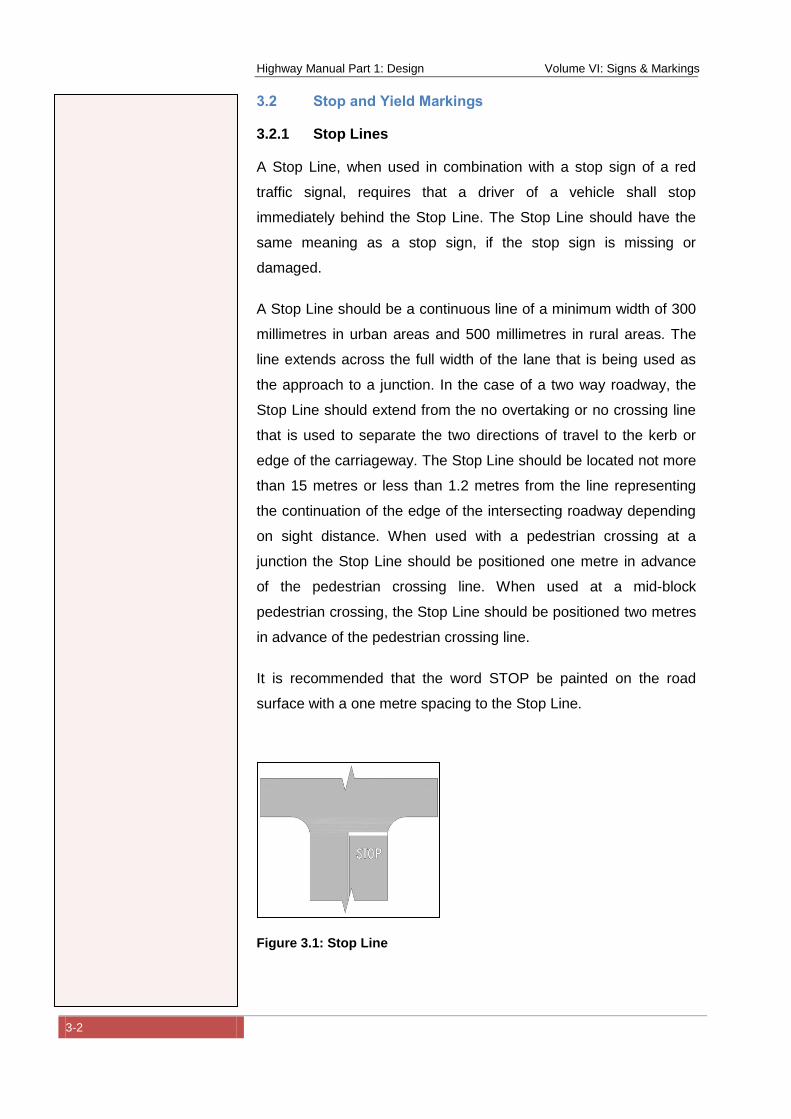
Highway Manual Part 1: Design Volume VI: Signs & Markings
3-2
3.2 Stop and Yield Markings
3.2.1 Stop Lines
A Stop Line, when used in combination with a stop sign of a red
traffic signal, requires that a driver of a vehicle shall stop
immediately behind the Stop Line. The Stop Line should have the
same meaning as a stop sign, if the stop sign is missing or
damaged.
A Stop Line should be a continuous line of a minimum width of 300
millimetres in urban areas and 500 millimetres in rural areas. The
line extends across the full width of the lane that is being used as
the approach to a junction. In the case of a two way roadway, the
Stop Line should extend from the no overtaking or no crossing line
that is used to separate the two directions of travel to the kerb or
edge of the carriageway. The Stop Line should be located not more
than 15 metres or less than 1.2 metres from the line representing
the continuation of the edge of the intersecting roadway depending
on sight distance. When used with a pedestrian crossing at a
junction the Stop Line should be positioned one metre in advance
of the pedestrian crossing line. When used at a mid-block
pedestrian crossing, the Stop Line should be positioned two metres
in advance of the pedestrian crossing line.
It is recommended that the word STOP be painted on the road
surface with a one metre spacing to the Stop Line.
Figure 3.1: Stop Line
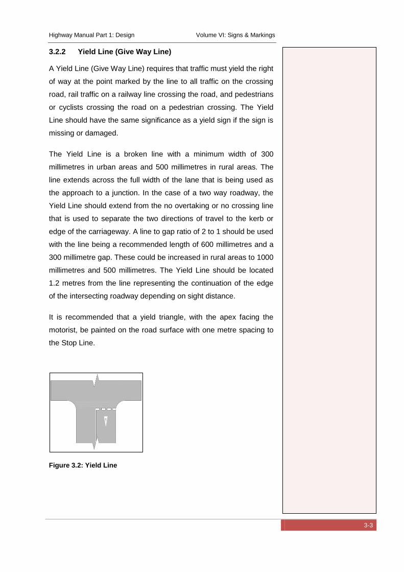
Highway Manual Part 1: Design Volume VI: Signs & Markings
3-3
3.2.2 Yield Line (Give Way Line)
A Yield Line (Give Way Line) requires that traffic must yield the right
of way at the point marked by the line to all traffic on the crossing
road, rail traffic on a railway line crossing the road, and pedestrians
or cyclists crossing the road on a pedestrian crossing. The Yield
Line should have the same significance as a yield sign if the sign is
missing or damaged.
The Yield Line is a broken line with a minimum width of 300
millimetres in urban areas and 500 millimetres in rural areas. The
line extends across the full width of the lane that is being used as
the approach to a junction. In the case of a two way roadway, the
Yield Line should extend from the no overtaking or no crossing line
that is used to separate the two directions of travel to the kerb or
edge of the carriageway. A line to gap ratio of 2 to 1 should be used
with the line being a recommended length of 600 millimetres and a
300 millimetre gap. These could be increased in rural areas to 1000
millimetres and 500 millimetres. The Yield Line should be located
1.2 metres from the line representing the continuation of the edge
of the intersecting roadway depending on sight distance.
It is recommended that a yield triangle, with the apex facing the
motorist, be painted on the road surface with one metre spacing to
the Stop Line.
Figure 3.2: Yield Line
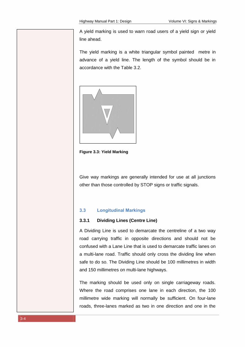
Highway Manual Part 1: Design Volume VI: Signs & Markings
3-4
A yield marking is used to warn road users of a yield sign or yield
line ahead.
The yield marking is a white triangular symbol painted metre in
advance of a yield line. The length of the symbol should be in
accordance with the Table 3.2.
Figure 3.3: Yield Marking
Give way markings are generally intended for use at all junctions
other than those controlled by STOP signs or traffic signals.
3.3 Longitudinal Markings
3.3.1 Dividing Lines (Centre Line)
A Dividing Line is used to demarcate the centreline of a two way
road carrying traffic in opposite directions and should not be
confused with a Lane Line that is used to demarcate traffic lanes on
a multi-lane road. Traffic should only cross the dividing line when
safe to do so. The Dividing Line should be 100 millimetres in width
and 150 millimetres on multi-lane highways.
The marking should be used only on single carriageway roads.
Where the road comprises one lane in each direction, the 100
millimetre wide marking will normally be sufficient. On four-lane
roads, three-lanes marked as two in one direction and one in the
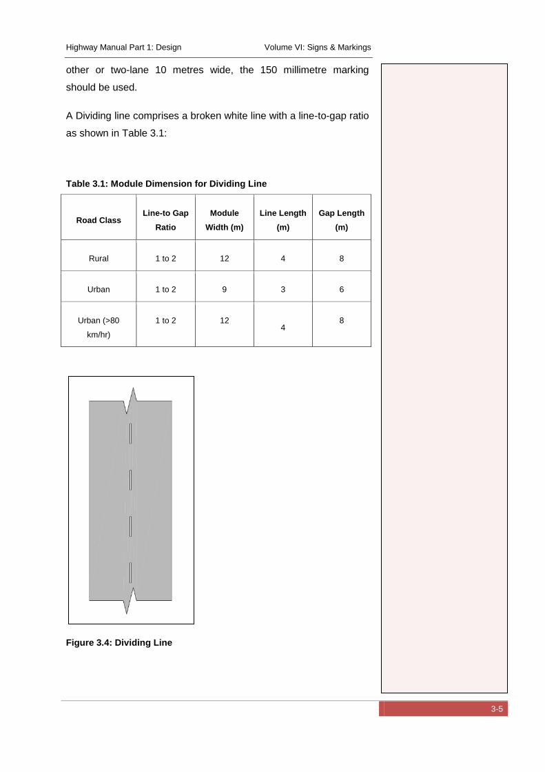
Highway Manual Part 1: Design Volume VI: Signs & Markings
3-5
other or two-lane 10 metres wide, the 150 millimetre marking
should be used.
A Dividing line comprises a broken white line with a line-to-gap ratio
as shown in Table 3.1:
Table 3.1: Module Dimension for Dividing Line
Road Class Line-to Gap
Ratio
Module
Width (m)
Line Length
(m)
Gap Length
(m)
Rural 1 to 2 12 4 8
Urban 1 to 2 9 3 6
Urban (>80
km/hr)
1 to 2 12 4
8
Figure 3.4: Dividing Line
Highway Manual Part 1: Design Volume VI: Signs & Markings
3-6
3.3.2 Traffic Lane Lines
Traffic lane lines are used demarcate traffic lanes for vehicles
travelling on a portion of roadway in the same direction. The traffic
lane lines are normally 100 millimetres in width and are white in
colour. Traffic lane lines normally consist of a broken line with
strokes of equal length separated by uniform gaps. The length of
the lines and gaps depends on the class of the road and the
application of the line. The traffic lane line is used on multi-lane
roads carrying traffic in the same direction.
Lane lines should be parallel to the centreline and should be
synchronised across the carriageway.
The Lane Line comprises a broken white line with a line-to-gap ratio
as shown in Table 3.2:
Table 3.2: Module Dimension for Lane Line
Road Class Line-to Gap
Ratio
Module
Width (m)
Line Length
(m)
Gap Length
(m)
Expressways and
Rural (>80 km/hr) 1 to 2 6 2 4
Urban (<80
km/hr) 1 to 2 4.5 1.5 3
Urban (>80
km/hr) 1 to 2 6 2 4
If an increased level of warning is needed, a gap to line ratio of 1 to
1 with dimensions of 1.5 metres to 1.5 metres.
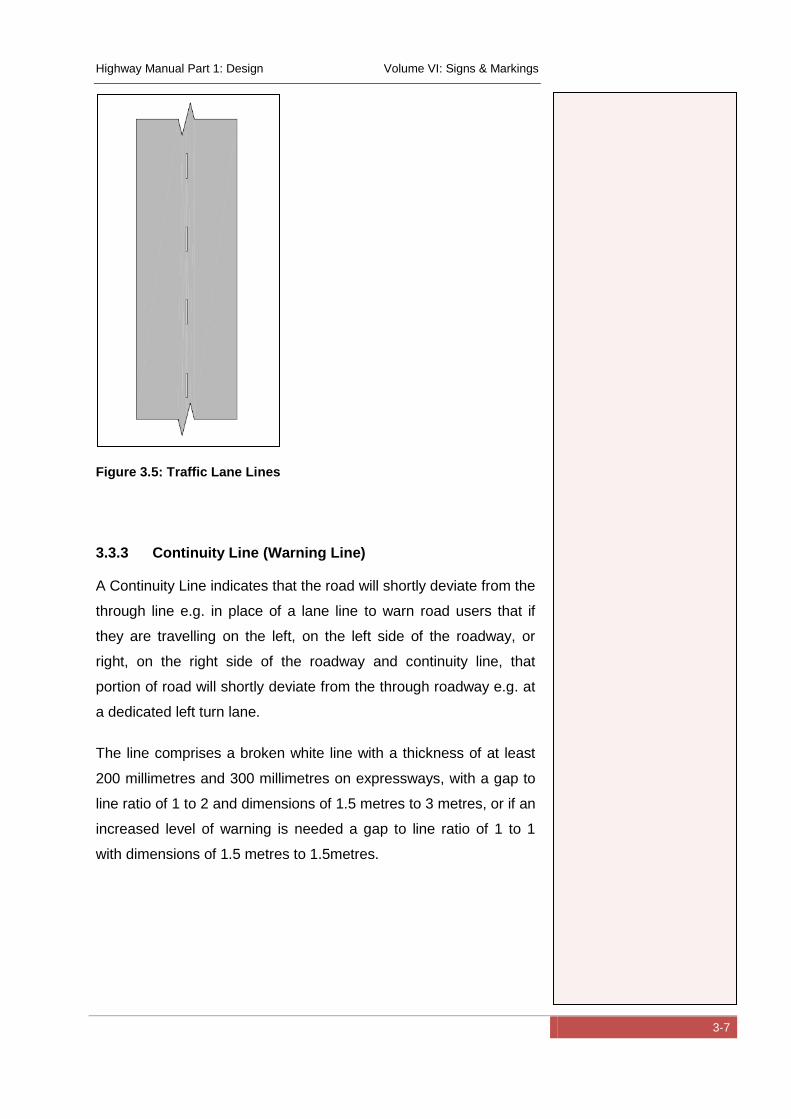
Highway Manual Part 1: Design Volume VI: Signs & Markings
3-7
Figure 3.5: Traffic Lane Lines
3.3.3 Continuity Line (Warning Line)
A Continuity Line indicates that the road will shortly deviate from the
through line e.g. in place of a lane line to warn road users that if
they are travelling on the left, on the left side of the roadway, or
right, on the right side of the roadway and continuity line, that
portion of road will shortly deviate from the through roadway e.g. at
a dedicated left turn lane.
The line comprises a broken white line with a thickness of at least
200 millimetres and 300 millimetres on expressways, with a gap to
line ratio of 1 to 2 and dimensions of 1.5 metres to 3 metres, or if an
increased level of warning is needed a gap to line ratio of 1 to 1
with dimensions of 1.5 metres to 1.5metres.
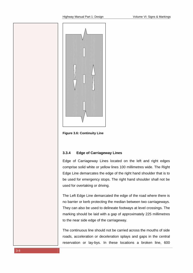
Highway Manual Part 1: Design Volume VI: Signs & Markings
3-8
Figure 3.6: Continuity Line
3.3.4 Edge of Carriageway Lines
Edge of Carriageway Lines located on the left and right edges
comprise solid white or yellow lines 100 millimetres wide. The Right
Edge Line demarcates the edge of the right hand shoulder that is to
be used for emergency stops. The right hand shoulder shall not be
used for overtaking or driving.
The Left Edge Line demarcated the edge of the road where there is
no barrier or kerb protecting the median between two carriageways.
They can also be used to delineate footways at level crossings. The
marking should be laid with a gap of approximately 225 millimetres
to the near side edge of the carriageway.
The continuous line should not be carried across the mouths of side
roads, acceleration or deceleration splays and gaps in the central
reservation or lay-bys. In these locations a broken line, 600
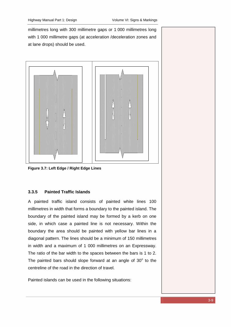
Highway Manual Part 1: Design Volume VI: Signs & Markings
3-9
millimetres long with 300 millimetre gaps or 1 000 millimetres long
with 1 000 millimetre gaps (at acceleration /deceleration zones and
at lane drops) should be used.
Figure 3.7: Left Edge / Right Edge Lines
3.3.5 Painted Traffic Islands
A painted traffic island consists of painted white lines 100
millimetres in width that forms a boundary to the painted island. The
boundary of the painted island may be formed by a kerb on one
side, in which case a painted line is not necessary. Within the
boundary the area should be painted with yellow bar lines in a
diagonal pattern. The lines should be a minimum of 150 millimetres
in width and a maximum of 1 000 millimetres on an Expressway.
The ratio of the bar width to the spaces between the bars is 1 to 2.
The painted bars should slope forward at an angle of 30o to the
centreline of the road in the direction of travel.
Painted islands can be used in the following situations:

Highway Manual Part 1: Design Volume VI: Signs & Markings
3-10
in advance of pedestrian refuge islands on two-way
roadways;
in advance of the start of a median island;
in advance of channelizing kerbed islands;
at freeway off-ramp gores;
at freeway on-ramp gores following 180° to 360° loop
ramps;
as a separator island between opposing flows of traffic when
there is insufficient space for a median island or barrier;
as a channelizing device to prevent straight through traffic
entering a turning lane which is in line across a junction from
a similar lane serving turning traffic in the opposite direction;
as a "shadow" island next to a kerbed island to control
general traffic movement but allow overrunning by extra-
large vehicles.
Figure 3.8: Painted Island
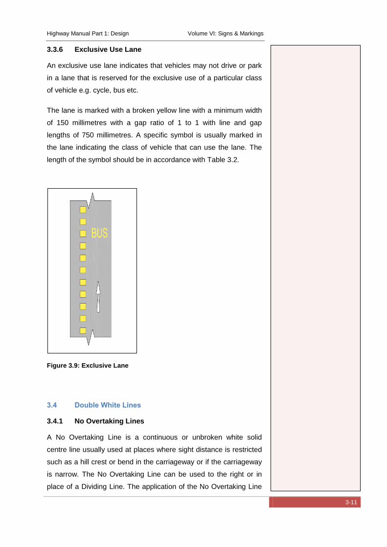
Highway Manual Part 1: Design Volume VI: Signs & Markings
3-11
3.3.6 Exclusive Use Lane
An exclusive use lane indicates that vehicles may not drive or park
in a lane that is reserved for the exclusive use of a particular class
of vehicle e.g. cycle, bus etc.
The lane is marked with a broken yellow line with a minimum width
of 150 millimetres with a gap ratio of 1 to 1 with line and gap
lengths of 750 millimetres. A specific symbol is usually marked in
the lane indicating the class of vehicle that can use the lane. The
length of the symbol should be in accordance with Table 3.2.
Figure 3.9: Exclusive Lane
3.4 Double White Lines
3.4.1 No Overtaking Lines
A No Overtaking Line is a continuous or unbroken white solid
centre line usually used at places where sight distance is restricted
such as a hill crest or bend in the carriageway or if the carriageway
is narrow. The No Overtaking Line can be used to the right or in
place of a Dividing Line. The application of the No Overtaking Line
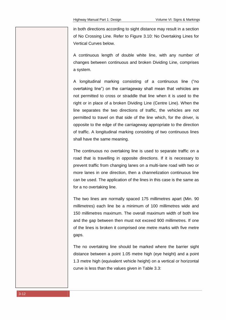
Highway Manual Part 1: Design Volume VI: Signs & Markings
3-12
in both directions according to sight distance may result in a section
of No Crossing Line. Refer to Figure 3.10: No Overtaking Lines for
Vertical Curves below.
A continuous length of double white line, with any number of
changes between continuous and broken Dividing Line, comprises
a system.
A longitudinal marking consisting of a continuous line (“no
overtaking line”) on the carriageway shall mean that vehicles are
not permitted to cross or straddle that line when it is used to the
right or in place of a broken Dividing Line (Centre Line). When the
line separates the two directions of traffic, the vehicles are not
permitted to travel on that side of the line which, for the driver, is
opposite to the edge of the carriageway appropriate to the direction
of traffic. A longitudinal marking consisting of two continuous lines
shall have the same meaning.
The continuous no overtaking line is used to separate traffic on a
road that is travelling in opposite directions. If it is necessary to
prevent traffic from changing lanes on a multi-lane road with two or
more lanes in one direction, then a channelization continuous line
can be used. The application of the lines in this case is the same as
for a no overtaking line.
The two lines are normally spaced 175 millimetres apart (Min. 90
millimetres) each line be a minimum of 100 millimetres wide and
150 millimetres maximum. The overall maximum width of both line
and the gap between then must not exceed 900 millimetres. If one
of the lines is broken it comprised one metre marks with five metre
gaps.
The no overtaking line should be marked where the barrier sight
distance between a point 1.05 metre high (eye height) and a point
1.3 metre high (equivalent vehicle height) on a vertical or horizontal
curve is less than the values given in Table 3.3:
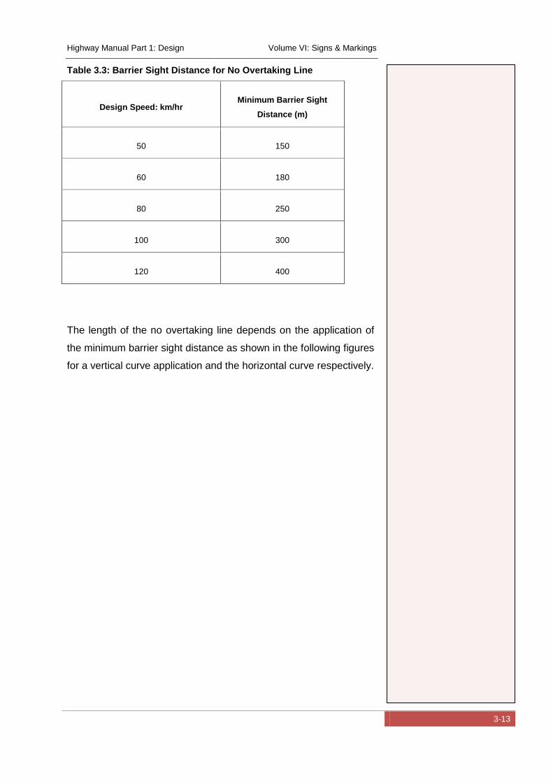
Highway Manual Part 1: Design Volume VI: Signs & Markings
3-13
Table 3.3: Barrier Sight Distance for No Overtaking Line
Design Speed: km/hr Minimum Barrier Sight
Distance (m)
50 150
60 180
80 250
100 300
120 400
The length of the no overtaking line depends on the application of
the minimum barrier sight distance as shown in the following figures
for a vertical curve application and the horizontal curve respectively.
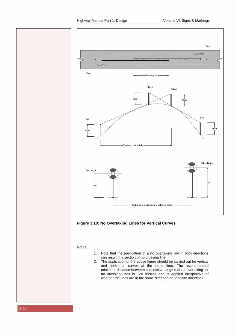
Highway Manual Part 1: Design Volume VI: Signs & Markings
3-14
Figure 3.10: No Overtaking Lines for Vertical Curves
Notes:
1. Note that the application of a no overtaking line in both directions can result in a section of no crossing line.
2. The application of the above figure should be carried out for vertical and horizontal curves at the same time. The recommended minimum distance between successive lengths of no overtaking or no crossing lines is 120 metres and is applied irrespective of whether the lines are in the same direction or opposite directions.
Highway Manual Part 1: Design Volume VI: Signs & Markings
3-15
Figure 3.11: No Overtaking Lines for Horizontal Curves
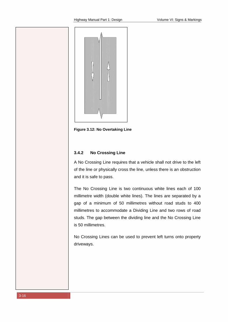
Highway Manual Part 1: Design Volume VI: Signs & Markings
3-16
Figure 3.12: No Overtaking Line
3.4.2 No Crossing Line
A No Crossing Line requires that a vehicle shall not drive to the left
of the line or physically cross the line, unless there is an obstruction
and it is safe to pass.
The No Crossing Line is two continuous white lines each of 100
millimetre width (double white lines). The lines are separated by a
gap of a minimum of 50 millimetres without road studs to 400
millimetres to accommodate a Dividing Line and two rows of road
studs. The gap between the dividing line and the No Crossing Line
is 50 millimetres.
No Crossing Lines can be used to prevent left turns onto property
driveways.
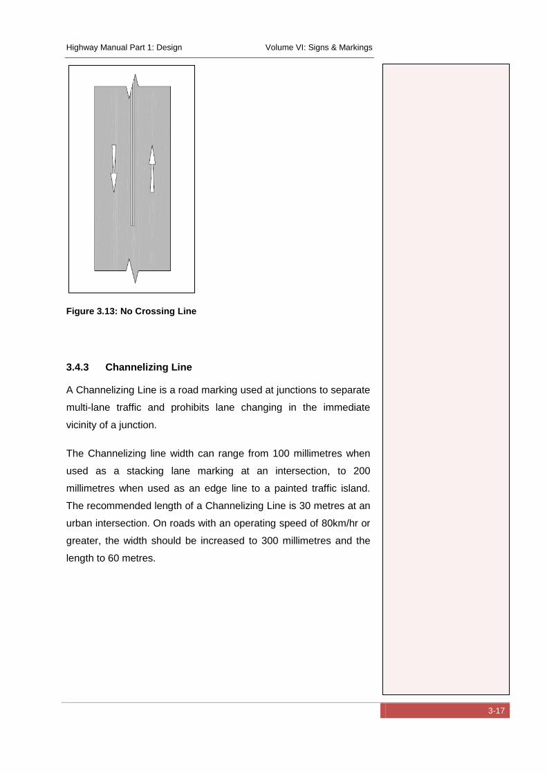
Highway Manual Part 1: Design Volume VI: Signs & Markings
3-17
Figure 3.13: No Crossing Line
3.4.3 Channelizing Line
A Channelizing Line is a road marking used at junctions to separate
multi-lane traffic and prohibits lane changing in the immediate
vicinity of a junction.
The Channelizing line width can range from 100 millimetres when
used as a stacking lane marking at an intersection, to 200
millimetres when used as an edge line to a painted traffic island.
The recommended length of a Channelizing Line is 30 metres at an
urban intersection. On roads with an operating speed of 80km/hr or
greater, the width should be increased to 300 millimetres and the
length to 60 metres.
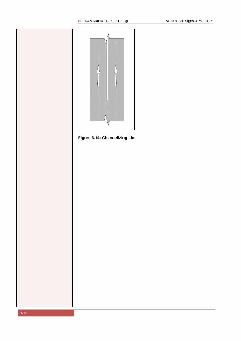
Highway Manual Part 1: Design Volume VI: Signs & Markings
3-18
Figure 3.14: Channelizing Line
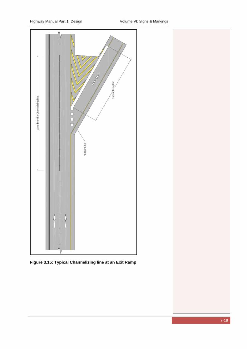
Highway Manual Part 1: Design Volume VI: Signs & Markings
3-19
Figure 3.15: Typical Channelizing line at an Exit Ramp
Highway Manual Part 1: Design Volume VI: Signs & Markings
3-20
3.5 Other Delineation Devices
3.5.1 Road studs (“Cats Eyes”)
Road studs or more commonly known “cats eyes” are devices
incorporating retro-reflective lenses that efficiently reflect the beams
of vehicles headlights. They are commonly used in combination
with road markings in situations where there may be poor visibility.
Road studs can be applied in different colours, commonly red,
yellow and white. In some countries the following meanings are
conveyed:
Red - means Prohibition
Yellow - means Warning
White – means Guidance
Situations where road studs may be warranted include:
Areas where there is regular mist, fog or rain resulting in
reduced visibility
Heavy traffic volumes resulting in glare and poor visibility
due to traffic density e.g. trucks
Poor road design standards e.g. sharp curves, narrow roads
High accident zones such as intersections, complex road
layouts and sharp curves
Construction zones with temporary deviations.
Road studs are placed centrally in the gaps between broken lines
or next to a continuous line with a 50 millimetre gap between the
line and the road stud. Road studs should be spaced to fall on a
common cross section across the road. The recommended
longitudinal spacing is:
Rural roads: 24 metres
Urban 18 metres
Highway Manual Part 1: Design Volume VI: Signs & Markings
3-21
Temporary: 12 metres
In abnormal situations the spacing can be reduced to three metres.
3.5.2 Guardrail (Crash barrier) Delineators
Guardrail delineators are retro-reflective devices used to warn road
users of the presence of a guardrail.
The delineators should be at least 70 cm2 and should be attached
to the guardrail at regular intervals.
3.6 Intersections
3.6.1 Guide Lines
Guide Lines are used to give guidance to motorists within a
junction.
A guide line is a broken white line with a width of 100 millimetres
and a gap to line ratio of 1 to 3 with dimensions of 500 millimetres
to 1.5 metres.
Guidelines can be used to provide straight through guidance,
turning guidance or by means of parallel lines and guidance to
pedestrians wanting to cross a road. E.g. for left turning traffic at a
dual carriageway intersection, the guide line indicates the most
efficient turning path to follow. This is particularly useful when there
is more than one turning lane.
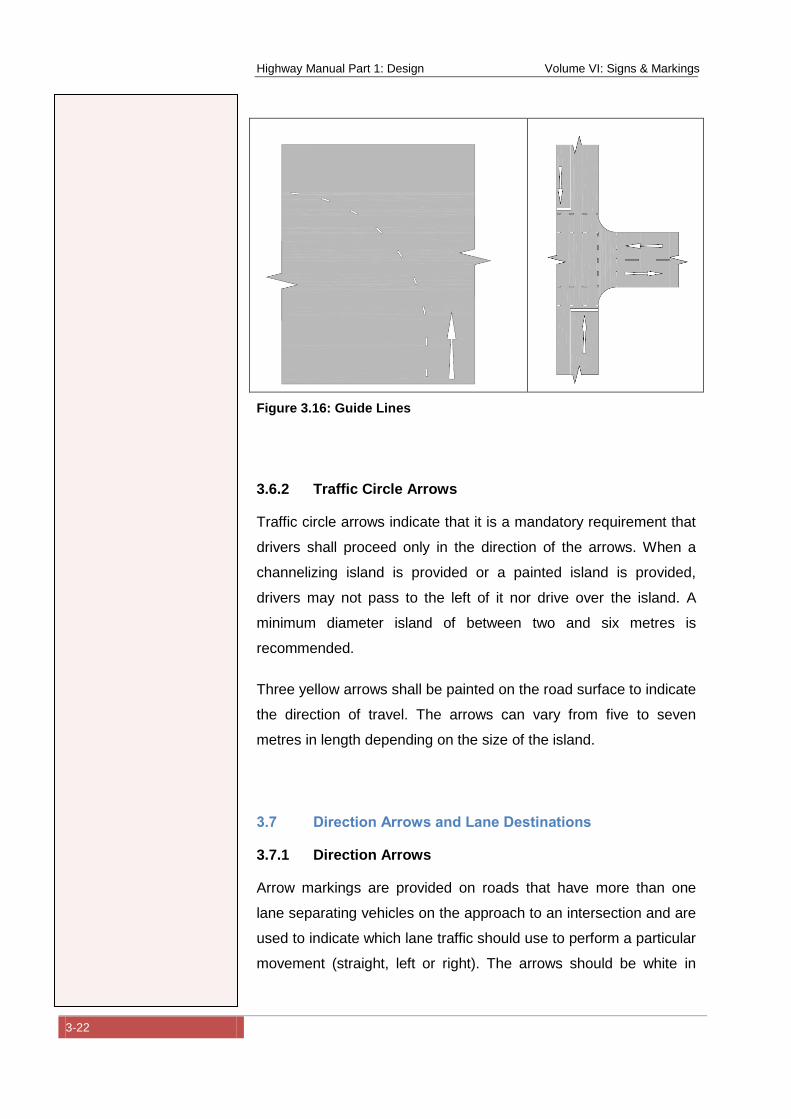
Highway Manual Part 1: Design Volume VI: Signs & Markings
3-22
Figure 3.16: Guide Lines
3.6.2 Traffic Circle Arrows
Traffic circle arrows indicate that it is a mandatory requirement that
drivers shall proceed only in the direction of the arrows. When a
channelizing island is provided or a painted island is provided,
drivers may not pass to the left of it nor drive over the island. A
minimum diameter island of between two and six metres is
recommended.
Three yellow arrows shall be painted on the road surface to indicate
the direction of travel. The arrows can vary from five to seven
metres in length depending on the size of the island.
3.7 Direction Arrows and Lane Destinations
3.7.1 Direction Arrows
Arrow markings are provided on roads that have more than one
lane separating vehicles on the approach to an intersection and are
used to indicate which lane traffic should use to perform a particular
movement (straight, left or right). The arrows should be white in
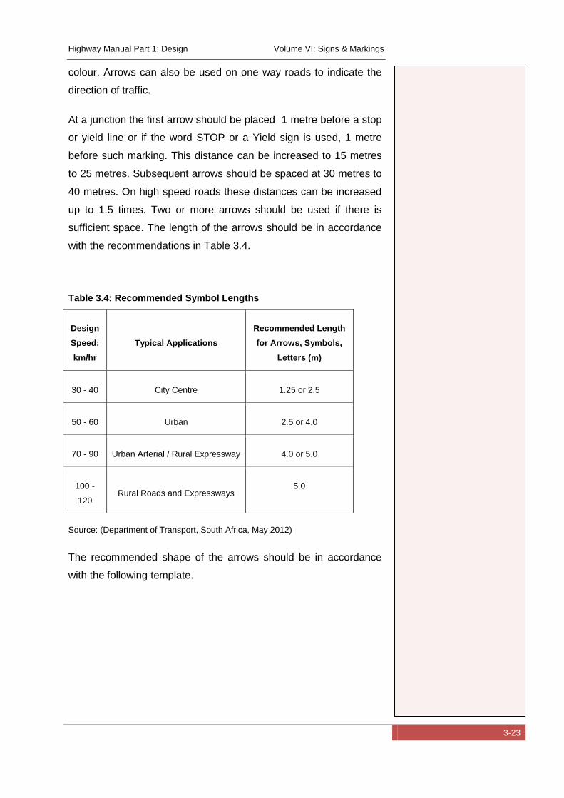
Highway Manual Part 1: Design Volume VI: Signs & Markings
3-23
colour. Arrows can also be used on one way roads to indicate the
direction of traffic.
At a junction the first arrow should be placed 1 metre before a stop
or yield line or if the word STOP or a Yield sign is used, 1 metre
before such marking. This distance can be increased to 15 metres
to 25 metres. Subsequent arrows should be spaced at 30 metres to
40 metres. On high speed roads these distances can be increased
up to 1.5 times. Two or more arrows should be used if there is
sufficient space. The length of the arrows should be in accordance
with the recommendations in Table 3.4.
Table 3.4: Recommended Symbol Lengths
Design
Speed:
km/hr
Typical Applications
Recommended Length
for Arrows, Symbols,
Letters (m)
30 - 40 City Centre 1.25 or 2.5
50 - 60 Urban 2.5 or 4.0
70 - 90 Urban Arterial / Rural Expressway 4.0 or 5.0
100 -
120 Rural Roads and Expressways
5.0
Source: (Department of Transport, South Africa, May 2012)
The recommended shape of the arrows should be in accordance
with the following template.
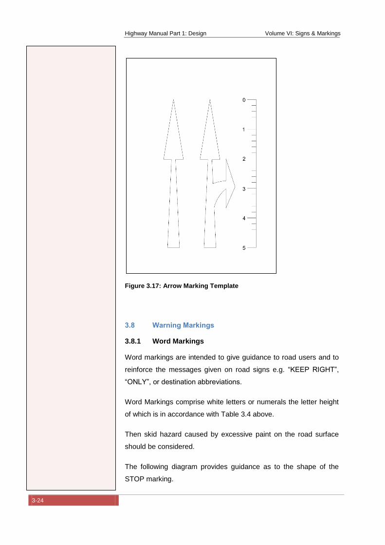
Highway Manual Part 1: Design Volume VI: Signs & Markings
3-24
Figure 3.17: Arrow Marking Template
3.8 Warning Markings
3.8.1 Word Markings
Word markings are intended to give guidance to road users and to
reinforce the messages given on road signs e.g. “KEEP RIGHT”,
“ONLY”, or destination abbreviations.
Word Markings comprise white letters or numerals the letter height
of which is in accordance with Table 3.4 above.
Then skid hazard caused by excessive paint on the road surface
should be considered.
The following diagram provides guidance as to the shape of the
STOP marking.
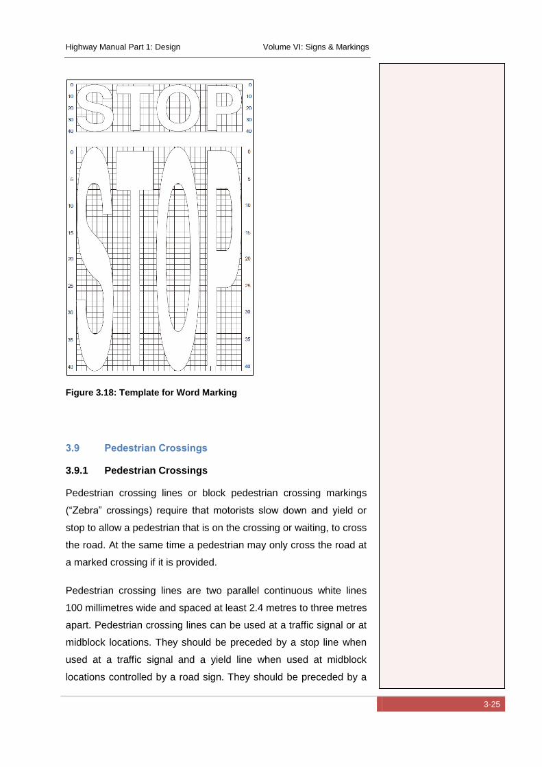
Highway Manual Part 1: Design Volume VI: Signs & Markings
3-25
Figure 3.18: Template for Word Marking
3.9 Pedestrian Crossings
3.9.1 Pedestrian Crossings
Pedestrian crossing lines or block pedestrian crossing markings
(“Zebra” crossings) require that motorists slow down and yield or
stop to allow a pedestrian that is on the crossing or waiting, to cross
the road. At the same time a pedestrian may only cross the road at
a marked crossing if it is provided.
Pedestrian crossing lines are two parallel continuous white lines
100 millimetres wide and spaced at least 2.4 metres to three metres
apart. Pedestrian crossing lines can be used at a traffic signal or at
midblock locations. They should be preceded by a stop line when
used at a traffic signal and a yield line when used at midblock
locations controlled by a road sign. They should be preceded by a

Highway Manual Part 1: Design Volume VI: Signs & Markings
3-26
pedestrian crossing sign. At midblock locations, they may be used
in combination with a block pedestrian crossing that is more visible.
Block pedestrian crossings are more visible than pedestrian
crossing lines and comprise rectangular painted markings of
minimum length 2.4 metres and a minimum width of 500
millimetres, and maximum width of 750 millimetres spaced 600
millimetres apart. In exceptional cases, the minimum width can be
reduced to 380 millimetres and maximum can be increased to 840
millimetres. They extend across the full width of the roadway. They
should be preceded by a stop line when used at a traffic signal and
a yield line when used at midblock locations controlled by a road
sign.
The yield line consists of a single broken line comprising 500
millimetre marks and 500 millimetre gaps, and is 200 millimetres
wide. It is normally sited between 1.1 metres and three metres from
the edge of the stripes on the crossing, whether or not studs are
used, and must extend across the full width of the carriageway.
This three metre limit may be increased up to 10 metres if
necessary.
Pedestrian crossings should only be marked at locations where
there is adequate sight distance.
Figure 3.19: Pedestrian Crossing
3.10 Parking
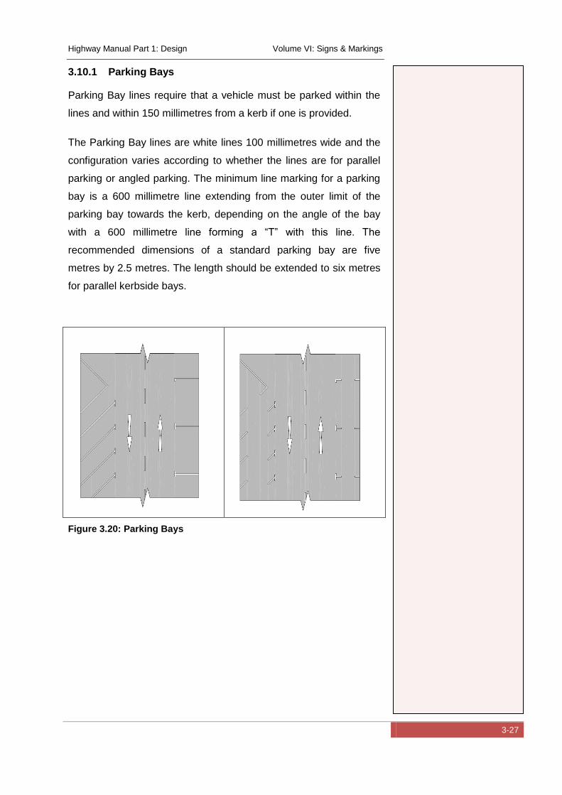
Highway Manual Part 1: Design Volume VI: Signs & Markings
3-27
3.10.1 Parking Bays
Parking Bay lines require that a vehicle must be parked within the
lines and within 150 millimetres from a kerb if one is provided.
The Parking Bay lines are white lines 100 millimetres wide and the
configuration varies according to whether the lines are for parallel
parking or angled parking. The minimum line marking for a parking
bay is a 600 millimetre line extending from the outer limit of the
parking bay towards the kerb, depending on the angle of the bay
with a 600 millimetre line forming a “T” with this line. The
recommended dimensions of a standard parking bay are five
metres by 2.5 metres. The length should be extended to six metres
for parallel kerbside bays.
Figure 3.20: Parking Bays

Highway Manual Part 1: Design Volume VI: Signs & Markings
4-1
4 Traffic Signals
4.1 Introduction
Traffic signals are standardised devices for the regulation and
control of vehicular traffic, pedestrians and pedal cyclists. They are
normally used at the following locations:
Signalised intersections
Signalised pedestrian and cyclist crossings
Control of public transport lanes
Temporary road works
Railway crossings
Traffic signals are complex in terms of their design, installation and
operation and should only be undertaken by qualified persons with
a high level of skill and experience. A typical traffic signal design
should comprise of the following information:
A scale drawing of the intersection to be signalized showing
the road layout and traffic lanes
The number, type and location of the traffic signal faces
Pedestrian and cyclist facilities
Traffic signal phasing, timing plans and offsets (to achieve
synchronization of traffic signals at consecutive
intersections)
Date of implementation and signature of approval of a
competent, suitable qualified person
The main objectives of traffic signals are as follows:
To reduce conflicts between vehicles and other traffic
(pedestrians and cyclists)
To enable pedestrians and cyclists to cross the road safely
To improve the capacity of an intersection
Highway Manual Part 1: Design Volume VI: Signs & Markings
4-2
To improve safety
To reduce delays to side road traffic
To provide for continuity of movement along a route
To warn of hazards
The provision of traffic signals is not always the best solution to a
particular situation and the following alternatives should also be
considered:
Redesign the geometry of the intersection to improve traffic
flow and safety e.g. the provision of a dedicated left turn
lane for turning traffic
The provision of a traffic circle
The provision of an interchange if there are high volumes of
traffic
The introduction of traffic management measures such as
one way streets, road closures and the banning of certain
turning movements
The introduction of traffic calming
A possible disadvantage of traffic signals is that they may only be
needed during the peak traffic flow hours. During off peak hours
when traffic flows are lower, the signal may create unnecessary
delays and lead to driver frustrations and traffic disobeying or
ignoring the traffic signal. The introduction of a traffic signal on a
main route may also lead to delays that did not previously occur.
The benefits of traffic signals must therefore be carefully
considered.
Highway Manual Part 1: Design Volume VI: Signs & Markings
4-3
4.2 Warrants for Traffic Signals
The installation of traffic signals should not be carried out unless
there has been an in-depth investigation to determine if they are
warranted in terms of their ability to improve traffic operations and
safety. It is also essential that there be an on-going commitment to
the maintenance of the signal installation.
The signalisation of an intersection should be provided where the
existing method of control, e.g. a stop or yield control, cannot cope
with the traffic flows and there are increasing delays and accidents
as a result. Delays are manifested by long queues of traffic on the
side roads waiting to cross or turn into the main road, and waiting to
turn left from the main road into the side road. There may also be
high volumes of pedestrians wanting to cross at an intersection. If
there are excessive delays at an intersection this can result in a
safety problem because drivers (and pedestrians) may become
frustrated at the delay and then take risks. This may result in an
increase in accidents at an intersection.
It should be realised that the installation of traffic signals may create
new delays for traffic on the main road, because drivers previously
did not have to stop, while reducing delays on a side road. The dis-
benefit to the traffic on the main road and the benefits in reduced
delays to traffic on the side road should be carefully considered.
A further factor to be considered is that where an intersection is not
isolated and is located near to other traffic signals, there may be
benefits in signalizing the intersection and coordinating the traffic
signal settings with the other intersections, in order to improve
traffic flow and overall delays on an area-wide basis.
As stated in section 4.1 above, the installation of traffic signals is
not always the best solution and the alternatives (e.g. geometric
improvement, mini circles etc.) should first receive consideration.
Many authorities adopt a system of “Warrants” with which the need
for traffic signals can be assessed, instead of carrying out a
detailed engineering analysis. Experience has shown in many
Highway Manual Part 1: Design Volume VI: Signs & Markings
4-4
countries that there is a level of traffic activity above which signals
are needed. Above this level delays become unacceptable and an
increase in traffic accidents can result.
The SADC Road Traffic Signs Manual (Department of Transport, South Africa, May
2012) uses the length of traffic queues as the criteria for establishing
if traffic signals are warranted. Queues can be comprised of
vehicles, pedestrians or cyclists stopped or waiting at a junction in a
single lane. The length of a queue is deemed to be proportional to
the total delay at the intersection and is an indication of the accident
potential. As queues build up, delays increase. The following queue
length warrants have been adopted in the SADC manual:
“The INSTALLATION of a traffic signal is deemed warranted at a
junction, pedestrian or pedal cyclist crossing when ANY one of the
following three queue length warrants are met:
WARRANT 1: The average length of ANY individual queue
equals or exceeds four (4) over any one hour of a normal
day.
WARRANT 2: The SUM of the average lengths of all
queues equals or exceeds six (6) over any one hour of a
normal day.
WARRANT 3: The SUM of the average lengths of all
queues equals or exceeds four (4) over each of any eight
hours of a normal day (the hours do not have to be
consecutive, but they may not overlap).”
The implementation of the above warrants requires extensive
surveys of traffic queues in the field. Queues are measured every
15 to 60 seconds on each approach lane over the required period
and are averaged.
A second method of determining average queue length is by means
of traffic modelling. This is not as accurate as conducting actual on
site surveys, but can be useful if field measurements are not
Highway Manual Part 1: Design Volume VI: Signs & Markings
4-5
possible or where a new intersection is being designed. A variety of
computer software is available which can determine average queue
lengths e.g. the SIDRA software mentioned in section 4.4 above.
Other methods typically use a series of empirical graphs on which
traffic flows on the main and minor approaches are plotted to
determine a warrant e.g. “Traffic Signal Warrants” published by the
Texas Transport Institute. (Institute, March 2008)
Reference should be made to the above sources should additional
technical detail be required.
It is recommended that the warrants for traffic signal control should
be determined by a suitably qualified and experienced Traffic
Engineer.
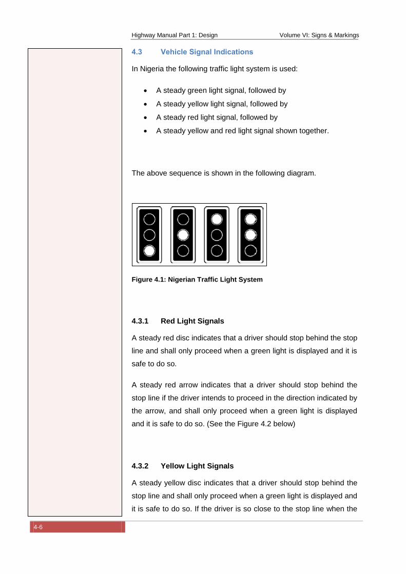
Highway Manual Part 1: Design Volume VI: Signs & Markings
4-6
4.3 Vehicle Signal Indications
In Nigeria the following traffic light system is used:
A steady green light signal, followed by
A steady yellow light signal, followed by
A steady red light signal, followed by
A steady yellow and red light signal shown together.
The above sequence is shown in the following diagram.
Figure 4.1: Nigerian Traffic Light System
4.3.1 Red Light Signals
A steady red disc indicates that a driver should stop behind the stop
line and shall only proceed when a green light is displayed and it is
safe to do so.
A steady red arrow indicates that a driver should stop behind the
stop line if the driver intends to proceed in the direction indicated by
the arrow, and shall only proceed when a green light is displayed
and it is safe to do so. (See the Figure 4.2 below)
4.3.2 Yellow Light Signals
A steady yellow disc indicates that a driver should stop behind the
stop line and shall only proceed when a green light is displayed and
it is safe to do so. If the driver is so close to the stop line when the
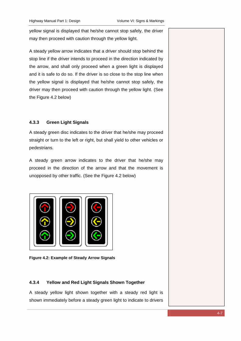
Highway Manual Part 1: Design Volume VI: Signs & Markings
4-7
yellow signal is displayed that he/she cannot stop safely, the driver
may then proceed with caution through the yellow light.
A steady yellow arrow indicates that a driver should stop behind the
stop line if the driver intends to proceed in the direction indicated by
the arrow, and shall only proceed when a green light is displayed
and it is safe to do so. If the driver is so close to the stop line when
the yellow signal is displayed that he/she cannot stop safely, the
driver may then proceed with caution through the yellow light. (See
the Figure 4.2 below)
4.3.3 Green Light Signals
A steady green disc indicates to the driver that he/she may proceed
straight or turn to the left or right, but shall yield to other vehicles or
pedestrians.
A steady green arrow indicates to the driver that he/she may
proceed in the direction of the arrow and that the movement is
unopposed by other traffic. (See the Figure 4.2 below)
Figure 4.2: Example of Steady Arrow Signals
4.3.4 Yellow and Red Light Signals Shown Together
A steady yellow light shown together with a steady red light is
shown immediately before a steady green light to indicate to drivers
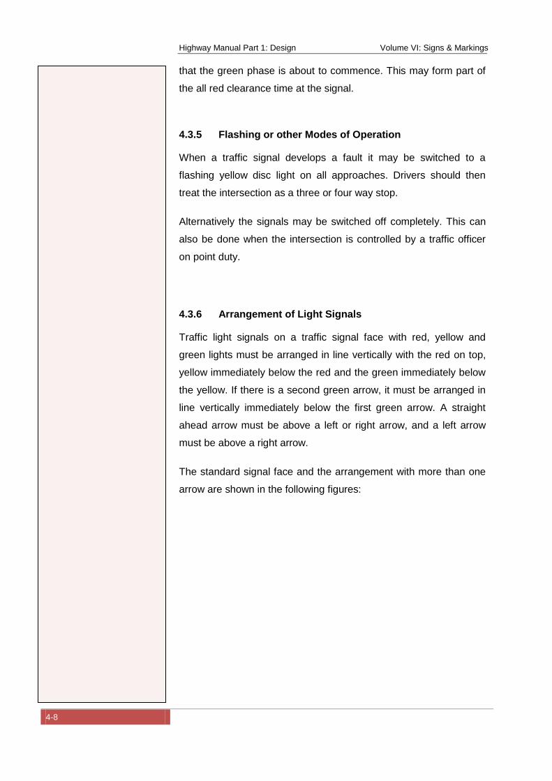
Highway Manual Part 1: Design Volume VI: Signs & Markings
4-8
that the green phase is about to commence. This may form part of
the all red clearance time at the signal.
4.3.5 Flashing or other Modes of Operation
When a traffic signal develops a fault it may be switched to a
flashing yellow disc light on all approaches. Drivers should then
treat the intersection as a three or four way stop.
Alternatively the signals may be switched off completely. This can
also be done when the intersection is controlled by a traffic officer
on point duty.
4.3.6 Arrangement of Light Signals
Traffic light signals on a traffic signal face with red, yellow and
green lights must be arranged in line vertically with the red on top,
yellow immediately below the red and the green immediately below
the yellow. If there is a second green arrow, it must be arranged in
line vertically immediately below the first green arrow. A straight
ahead arrow must be above a left or right arrow, and a left arrow
must be above a right arrow.
The standard signal face and the arrangement with more than one
arrow are shown in the following figures:
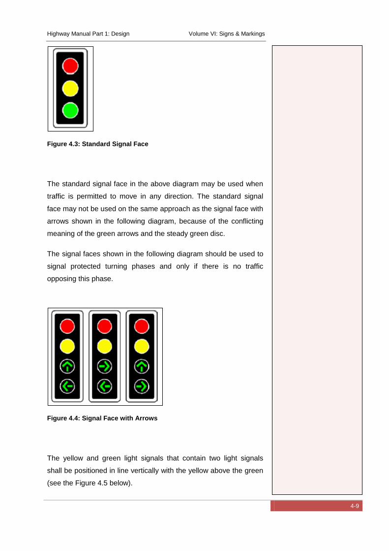
Highway Manual Part 1: Design Volume VI: Signs & Markings
4-9
Figure 4.3: Standard Signal Face
The standard signal face in the above diagram may be used when
traffic is permitted to move in any direction. The standard signal
face may not be used on the same approach as the signal face with
arrows shown in the following diagram, because of the conflicting
meaning of the green arrows and the steady green disc.
The signal faces shown in the following diagram should be used to
signal protected turning phases and only if there is no traffic
opposing this phase.
Figure 4.4: Signal Face with Arrows
The yellow and green light signals that contain two light signals
shall be positioned in line vertically with the yellow above the green
(see the Figure 4.5 below).
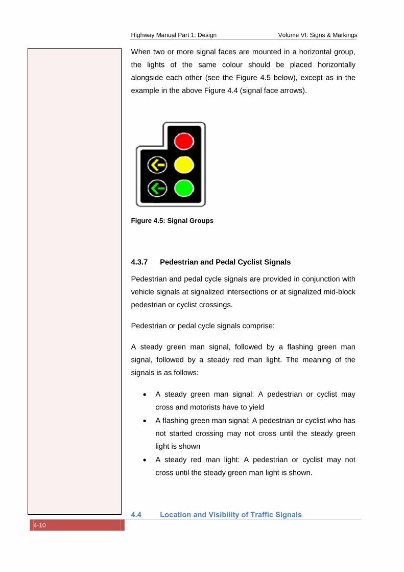
Highway Manual Part 1: Design Volume VI: Signs & Markings
4-10
When two or more signal faces are mounted in a horizontal group,
the lights of the same colour should be placed horizontally
alongside each other (see the Figure 4.5 below), except as in the
example in the above Figure 4.4 (signal face arrows).
Figure 4.5: Signal Groups
4.3.7 Pedestrian and Pedal Cyclist Signals
Pedestrian and pedal cycle signals are provided in conjunction with
vehicle signals at signalized intersections or at signalized mid-block
pedestrian or cyclist crossings.
Pedestrian or pedal cycle signals comprise:
A steady green man signal, followed by a flashing green man
signal, followed by a steady red man light. The meaning of the
signals is as follows:
A steady green man signal: A pedestrian or cyclist may
cross and motorists have to yield
A flashing green man signal: A pedestrian or cyclist who has
not started crossing may not cross until the steady green
light is shown
A steady red man light: A pedestrian or cyclist may not
cross until the steady green man light is shown.
4.4 Location and Visibility of Traffic Signals
Highway Manual Part 1: Design Volume VI: Signs & Markings
4-11
Traffic signal faces for use at junctions comprise of “Principle”
signal faces that are required to meet minimum safety standards
and legal requirements, and “Supplementary” signal faces that are
required to improve visibility, safety standards and traffic
operations.
4.4.1 Number and Location of Traffic Signal Faces
The following “Principle” traffic signal faces are required at a
signalized junction, slipway or signalized crossing to control traffic
on each approach:
At least two “Principle” traffic signal faces on the near side
of the junction positioned approximately on the extension of
the stop line, one on the left and one on the right of the
road. If the road is a dual carriageway with a constructed
median island at least 1.2 metres wide, then the left hand
traffic signal face should be positioned on the median island.
The two traffic signal faces should not be more than 16 to
20 metres apart.
If a separate left turn signal face is to be provided, at least
two “Principle” traffic signal faces incorporating a left turn
arrow must be provided, one on the near side and one on
either the far side or near side of the junction.
When a separate right turn signal face is required, at least
one “Principle” signal face incorporating a right turn arrow
should be provided on the near side of the junction.
Even if the above minimum requirements are met, additional
signal faces can be provided if required to improve visibility.
It should be noted that if a protected left turn phase is provided
using the traffic signal face shown in Figure 4.4 and Figure 4.5, the
left turn phase cannot be provided at the same time as the main
signal phase, due to the conflicting meaning of the steady green
arrow and the steady green disc.
Highway Manual Part 1: Design Volume VI: Signs & Markings
4-12
On high speed roads the speed limit on the approach to a traffic
signal should not exceed 80 km/hr. If the speed limit is higher than
70 km/hr, high intensity traffic signals or overhead gantry traffic
signals should be used. High visibility warning signs, a skid
resistant road surface or traffic calming (rumble strips) should be
used on the approach.
4.4.2 Visibility and Mounting of Traffic Signal Faces
Under normal conditions traffic signal faces should be clearly
visible. Consideration should be given to the provision of high
intensity traffic lights on high speed roads (80 km/hr) and other
locations e.g. where the light may be affected by setting sun or
where there is a cluttered background caused by other lights or
signs.
The traffic signal can also be equipped with black backing boards or
protective cones over the lenses to improve visibility. It is also
recommended that the poles on which the traffic lights are erected
should be painted yellow. Reflective strips can also be placed on
the supporting poles.
Traffic signals should comply with minimum sight distances
required as indicated in Table 4.1.
:
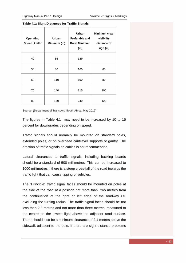
Highway Manual Part 1: Design Volume VI: Signs & Markings
4-13
Table 4.1: Sight Distances for Traffic Signals
Operating
Speed: km/hr
Urban
Minimum (m)
Urban
Preferable and
Rural Minimum
(m)
Minimum clear
visibility
distance of
sign (m)
40 55 130
50 80 160 60
60 110 190 80
70 140 215 100
80 170 240 120
Source: (Department of Transport, South Africa, May 2012)
The figures in Table 4.1 may need to be increased by 10 to 15
percent for downgrades depending on speed.
Traffic signals should normally be mounted on standard poles,
extended poles, or on overhead cantilever supports or gantry. The
erection of traffic signals on cables is not recommended.
Lateral clearances to traffic signals, including backing boards
should be a standard of 500 millimetres. This can be increased to
1000 millimetres if there is a steep cross-fall of the road towards the
traffic light that can cause tipping of vehicles.
The “Principle” traffic signal faces should be mounted on poles at
the side of the road at a position not more than two metres from
the continuation of the right or left edge of the roadway i.e.
excluding the turning radius. The traffic signal faces should be not
less than 2.3 metres and not more than three metres, measured to
the centre on the lowest light above the adjacent road surface.
There should also be a minimum clearance of 2.1 metres above the
sidewalk adjacent to the pole. If there are sight distance problems
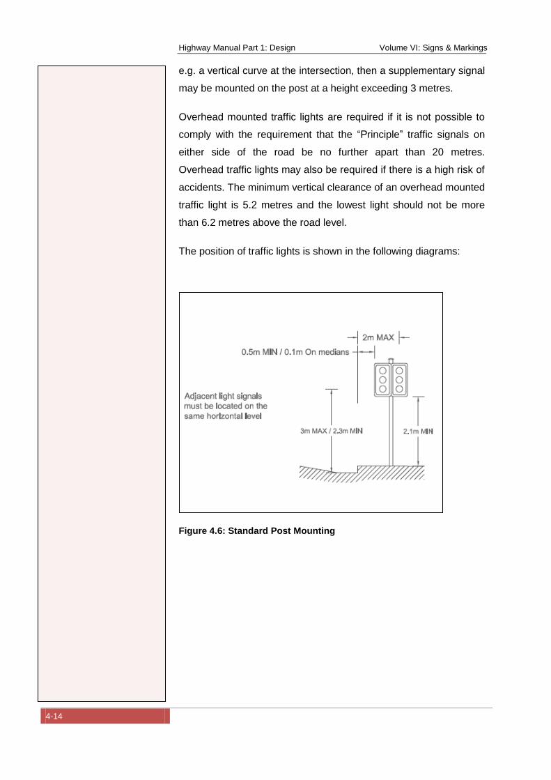
Highway Manual Part 1: Design Volume VI: Signs & Markings
4-14
e.g. a vertical curve at the intersection, then a supplementary signal
may be mounted on the post at a height exceeding 3 metres.
Overhead mounted traffic lights are required if it is not possible to
comply with the requirement that the “Principle” traffic signals on
either side of the road be no further apart than 20 metres.
Overhead traffic lights may also be required if there is a high risk of
accidents. The minimum vertical clearance of an overhead mounted
traffic light is 5.2 metres and the lowest light should not be more
than 6.2 metres above the road level.
The position of traffic lights is shown in the following diagrams:
Figure 4.6: Standard Post Mounting
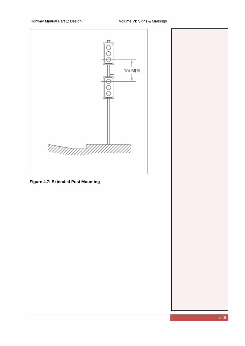
Highway Manual Part 1: Design Volume VI: Signs & Markings
4-15
Figure 4.7: Extended Post Mounting
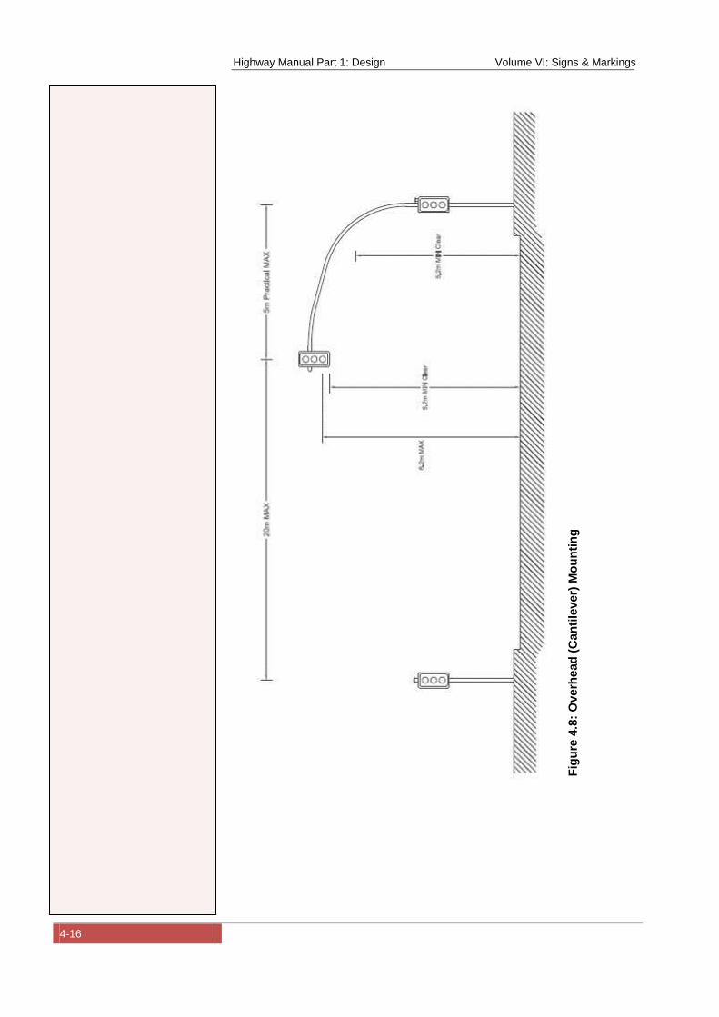
Highway Manual Part 1: Design Volume VI: Signs & Markings
4-16
Fig
ure
4.8
: O
ve
rhead
(C
an
tile
ver)
Mo
un
tin
g
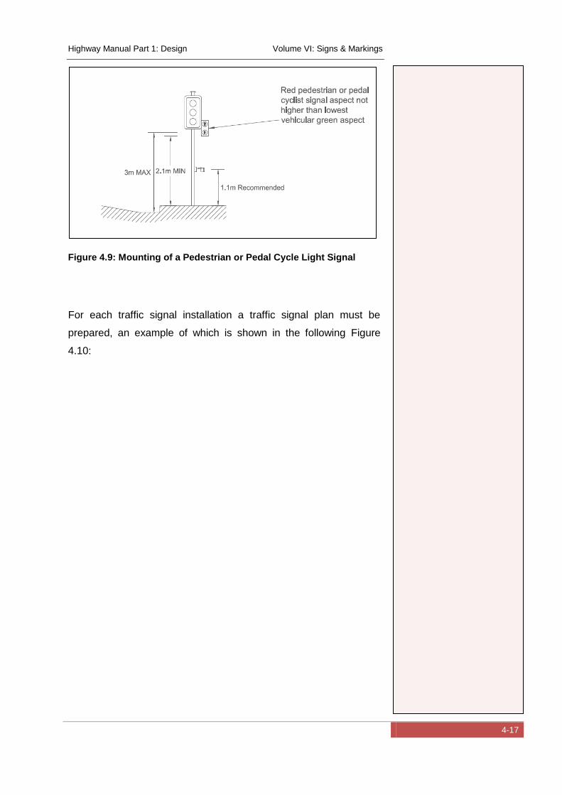
Highway Manual Part 1: Design Volume VI: Signs & Markings
4-17
Figure 4.9: Mounting of a Pedestrian or Pedal Cycle Light Signal
For each traffic signal installation a traffic signal plan must be
prepared, an example of which is shown in the following Figure
4.10:
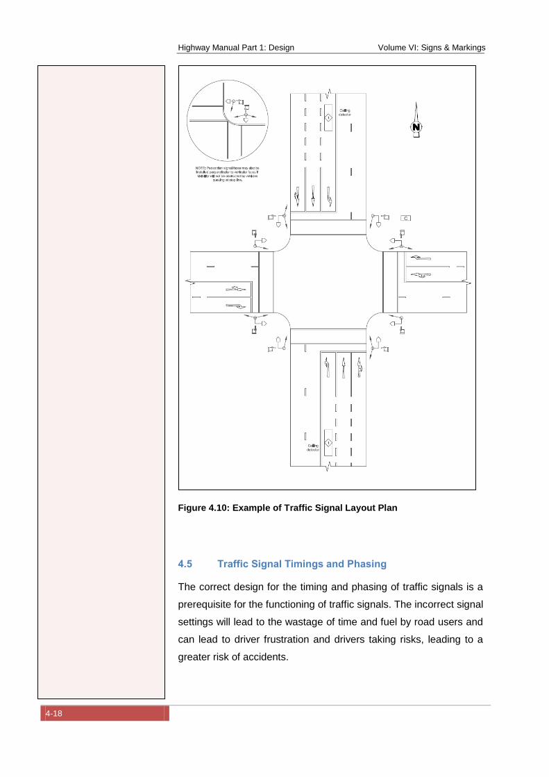
Highway Manual Part 1: Design Volume VI: Signs & Markings
4-18
Figure 4.10: Example of Traffic Signal Layout Plan
4.5 Traffic Signal Timings and Phasing
The correct design for the timing and phasing of traffic signals is a
prerequisite for the functioning of traffic signals. The incorrect signal
settings will lead to the wastage of time and fuel by road users and
can lead to driver frustration and drivers taking risks, leading to a
greater risk of accidents.
Highway Manual Part 1: Design Volume VI: Signs & Markings
4-19
Proper design of traffic signals requires careful planning, the
collection of data, the analysis of the data, and the calculation of the
most efficient signal timings to minimize delays at the intersection.
Several modes of operation of traffic signals are available
depending on the circumstances, including fixed time signals,
vehicle actuated control and traffic responsive control.
The design of traffic signals and traffic signal timings requires a
high level of expertise and experience and should be carried out by
a qualified Traffic Engineer.
The first step in any design is to collect comprehensive information
on the current situation at an intersection. This can range from a
scale drawing of the intersection showing road widths, lanes and
any existing signs and street furniture, to a comprehensive traffic
survey of existing traffic volumes per approach and lane. The traffic
count should at least cover the morning and afternoon peak two
hours as well as the heaviest off peak two hours.
The technical methodology required is beyond the scope of this
Guideline. There are several references that should be consulted if
further information is required, such as the following:
Transport Research Board, 1997, Highway Capacity
Manual, Special Report, National Research Council,
Washington.
Webster F.V. 1958, Traffic Signal Settings, Road Research
Technical Paper No 39, Road Research Laboratory, U.K.
Webster F.V. and Cobb B.M. 1966, Traffic Signals, Road
Research Technical Paper No 56, Road Research
Laboratory, U.K.
Department of Transport, SADC Road Traffic Signs Manual
– Digitised Version, May 2012.
In addition excellent software is available that can assist in traffic
signal design. One of the best known is the following:
Highway Manual Part 1: Design Volume VI: Signs & Markings
4-20
“SIDRA INTERSECTION” - According to the website SIDRA
Intersection is “a powerful software package for timing, capacity,
performance and level of service analysis of signalised
intersections (junctions controlled by traffic lights) including signal
coordination effects. It uses an advanced critical movement
analysis method allowing for overlap movements and movements
with two green periods per cycle, and determines signal timings
using fixed-time / pre-timed and actuated signal analysis methods
for any intersection geometry, allowing for simple as well as
complex phasing arrangements involving overlap movements.” The
software is available from: http://www.sidrasolutions.com/
Highway Manual Part 1: Design Volume VI: Signs & Markings
5-1
5 Application of Traffic Signs, Road Markings and
Signals
5.1 Longitudinal Placement
The longitudinal placement of signs is governed by the speed of the
approaching vehicles and the greater the speed, the further in
advance the sign needs to be positioned. This is necessary to
provide the driver with time to react and respond to the message
conveyed by the sign. The longitudinal position of signs also
depends on the point of reference they refer to, for example, the
beginning or end of road section to which a regulatory control
applies, a road hazard e.g. a sharp curve or an intersection.
It is essential that drivers have an unobstructed view of the sign and
the sight line should be free of obstructions e.g. foliage, other signs
etc. The sight line also depends on speed and the higher the
speed, the greater the distance needs to be.
Signs should be placed on the right hand side of the road; however
some signs may be placed on the left hand side of the road as well
for additional emphasis or if there is no convenient visible position
on the right hand side.
5.1.1 Longitudinal Placement of Regulatory and Warning Signs
Generally, regulatory signs are placed at or as close as possible to
the point to which they refer e.g. a STOP sign should be placed at
the stop line. Other signs that are placed at the beginning of a
section of road that has a restriction e.g. OVERTAKING
PROHIBITED and apply over a specific length of road, following
which they must be repeated.
Warning signs are generally place a specific distance in advance of
a hazard. The distance depends on the speed of the vehicle to
provide the driver with reaction time.
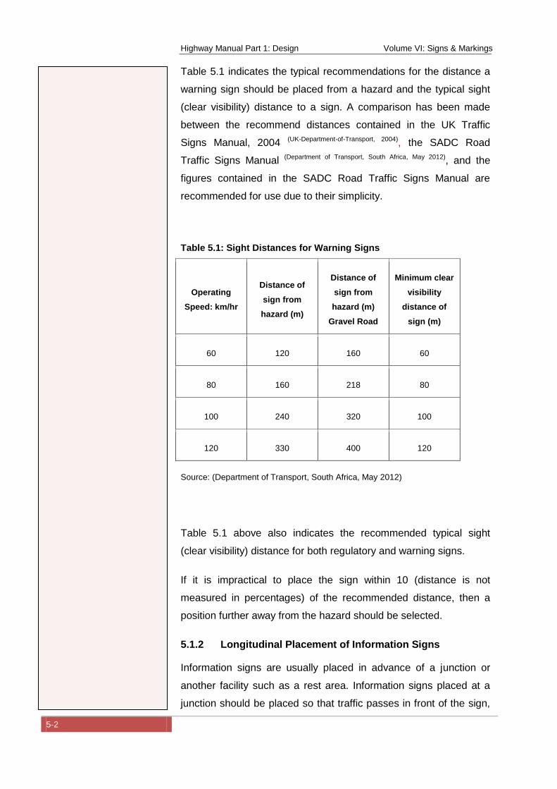
Highway Manual Part 1: Design Volume VI: Signs & Markings
5-2
Table 5.1 indicates the typical recommendations for the distance a
warning sign should be placed from a hazard and the typical sight
(clear visibility) distance to a sign. A comparison has been made
between the recommend distances contained in the UK Traffic
Signs Manual, 2004 (UK-Department-of-Transport, 2004), the SADC Road
Traffic Signs Manual (Department of Transport, South Africa, May 2012), and the
figures contained in the SADC Road Traffic Signs Manual are
recommended for use due to their simplicity.
Table 5.1: Sight Distances for Warning Signs
Operating
Speed: km/hr
Distance of
sign from
hazard (m)
Distance of
sign from
hazard (m)
Gravel Road
Minimum clear
visibility
distance of
sign (m)
60 120 160 60
80 160 218 80
100 240 320 100
120 330 400 120
Source: (Department of Transport, South Africa, May 2012)
Table 5.1 above also indicates the recommended typical sight
(clear visibility) distance for both regulatory and warning signs.
If it is impractical to place the sign within 10 (distance is not
measured in percentages) of the recommended distance, then a
position further away from the hazard should be selected.
5.1.2 Longitudinal Placement of Information Signs
Information signs are usually placed in advance of a junction or
another facility such as a rest area. Information signs placed at a
junction should be placed so that traffic passes in front of the sign,
Highway Manual Part 1: Design Volume VI: Signs & Markings
5-3
particularly when the junction is controlled by a stop, yield or traffic
signal. This allows the maximum time for the driver to read the sign.
On class “D” Secondary Roads with an operating speed of up to
100 km/hr. the minimum spacing of information signs should be 80
metres and a longitudinal spacing of 150 to 300 metres is
recommended. On an expressway, freeway or arterial road, Class
“A, B and C”, the recommended minimum spacing should be 200
metres.
On minor local roads, Class “E”, in dense urban areas, space
constraints usually dictate the placement of information signs and
care must be taken not to obscure other regulatory or warning
signs.
When placing signs, care must be taken that the sign is not
obscured by vegetation or street furniture etc.
The following figure indicates the recommended information sign
sequence at a junction between Class “A” or “F” roads.
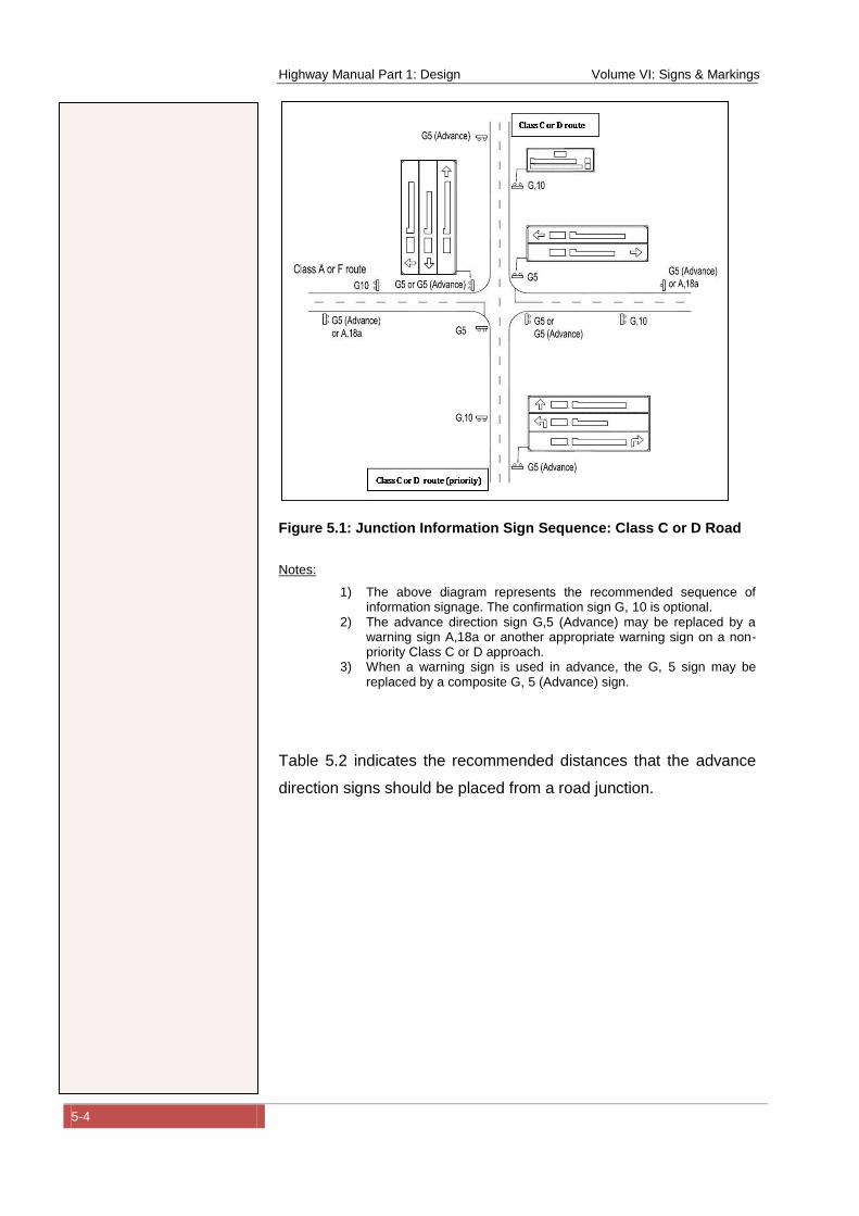
Highway Manual Part 1: Design Volume VI: Signs & Markings
5-4
Figure 5.1: Junction Information Sign Sequence: Class C or D Road
Notes:
1) The above diagram represents the recommended sequence of information signage. The confirmation sign G, 10 is optional.
2) The advance direction sign G,5 (Advance) may be replaced by a warning sign A,18a or another appropriate warning sign on a non-priority Class C or D approach.
3) When a warning sign is used in advance, the G, 5 sign may be replaced by a composite G, 5 (Advance) sign.
Table 5.2 indicates the recommended distances that the advance
direction signs should be placed from a road junction.

Highway Manual Part 1: Design Volume VI: Signs & Markings
5-5
Table 5.2: Distance of Advance Direction Signs from a Road Junction
Operating
Speed on the
Approach
km/hr
Operating Speed at Road Junction km/hr
20 40 60 80m
60 120m 90m 65m 65m
80 155 –
180m
140 –
165m 80m 80m
100 245 –
300m
220 –
275m 155m 130m
120 320 –
390m
310 –
360m
275 –
300m 145m
Source: (Department of Transport, South Africa, May 2012)
Note:
1) The longer distances should be used for gravel roads to allow for more gradual deceleration.
Figure 5.2 indicates the recommend sequence and placement of
signage at a diamond access interchange where the exit ramps
terminate at an at-grade junction.
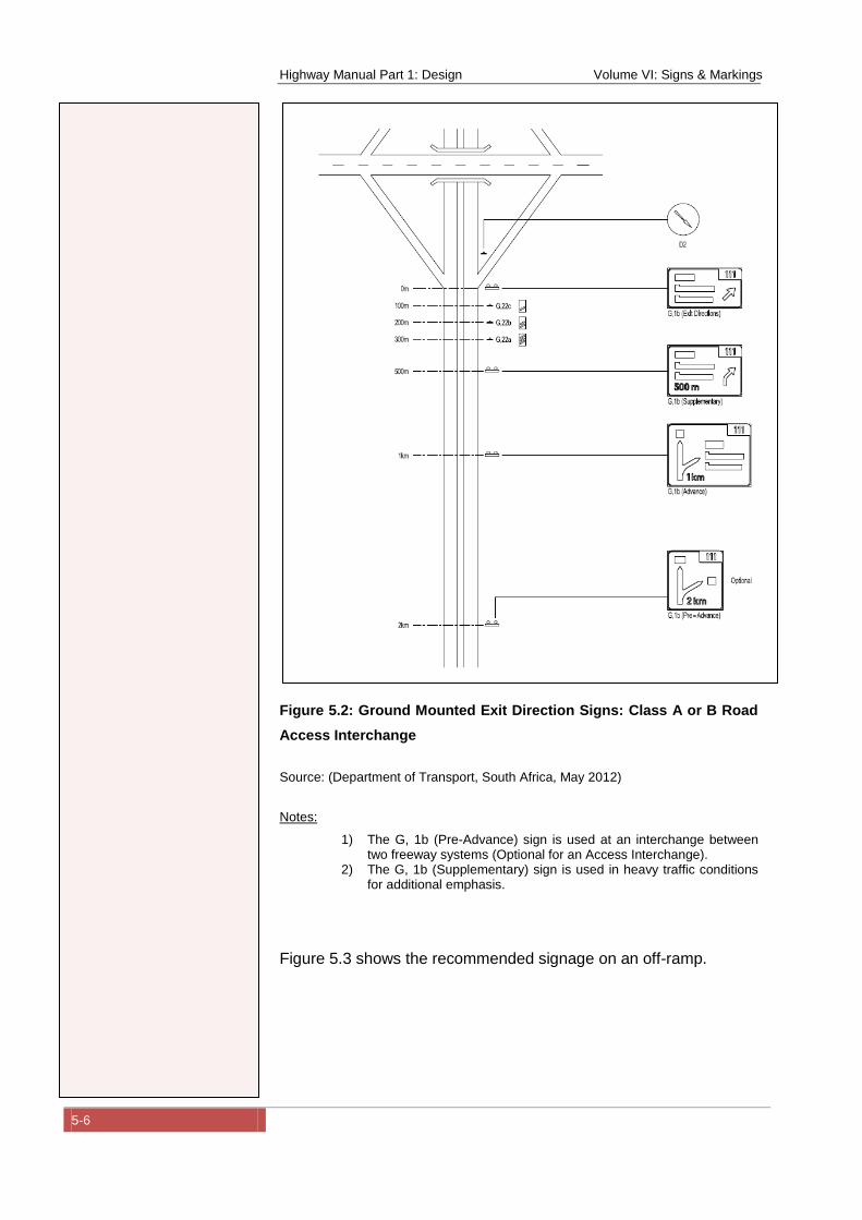
Highway Manual Part 1: Design Volume VI: Signs & Markings
5-6
Figure 5.2: Ground Mounted Exit Direction Signs: Class A or B Road
Access Interchange
Source: (Department of Transport, South Africa, May 2012)
Notes:
1) The G, 1b (Pre-Advance) sign is used at an interchange between two freeway systems (Optional for an Access Interchange).
2) The G, 1b (Supplementary) sign is used in heavy traffic conditions for additional emphasis.
Figure 5.3 shows the recommended signage on an off-ramp.
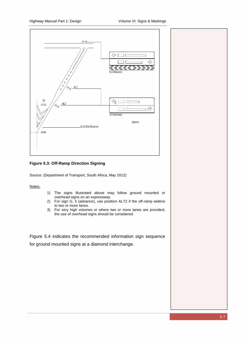
Highway Manual Part 1: Design Volume VI: Signs & Markings
5-7
Figure 5.3: Off-Ramp Direction Signing
Source: (Department of Transport, South Africa, May 2012)
Notes:
1) The signs illustrated above may follow ground mounted or overhead signs on an expressway.
2) For sign G, 5 (advance), use position ALT2 if the off-ramp widens to two or more lanes.
3) For very high volumes or where two or more lanes are provided, the use of overhead signs should be considered.
Figure 5.4 indicates the recommended information sign sequence
for ground mounted signs at a diamond interchange.
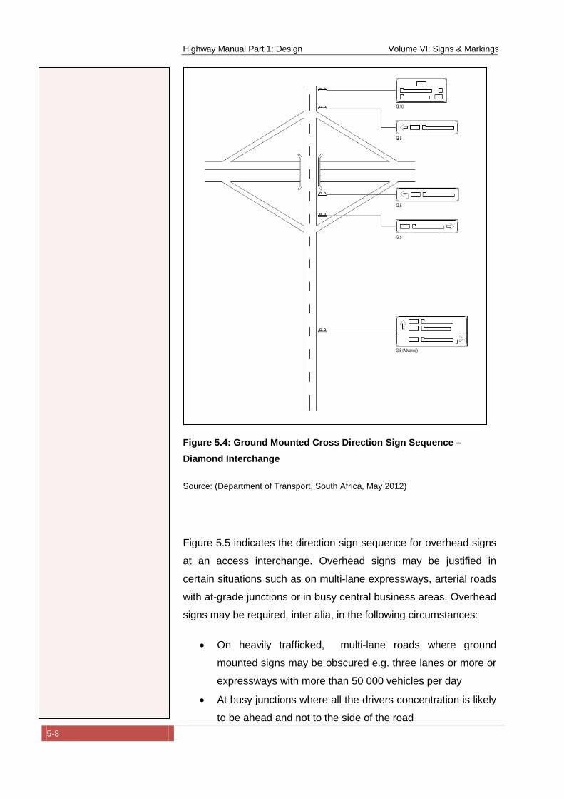
Highway Manual Part 1: Design Volume VI: Signs & Markings
5-8
Figure 5.4: Ground Mounted Cross Direction Sign Sequence –
Diamond Interchange
Source: (Department of Transport, South Africa, May 2012)
Figure 5.5 indicates the direction sign sequence for overhead signs
at an access interchange. Overhead signs may be justified in
certain situations such as on multi-lane expressways, arterial roads
with at-grade junctions or in busy central business areas. Overhead
signs may be required, inter alia, in the following circumstances:
On heavily trafficked, multi-lane roads where ground
mounted signs may be obscured e.g. three lanes or more or
expressways with more than 50 000 vehicles per day
At busy junctions where all the drivers concentration is likely
to be ahead and not to the side of the road
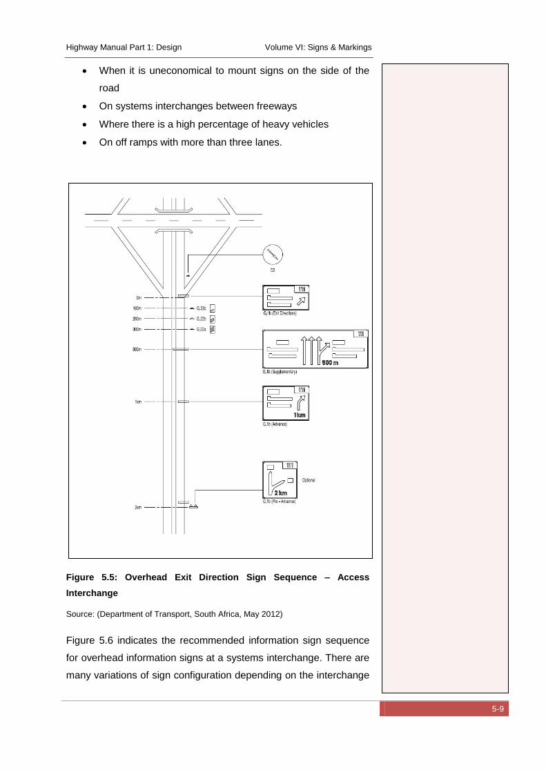
Highway Manual Part 1: Design Volume VI: Signs & Markings
5-9
When it is uneconomical to mount signs on the side of the
road
On systems interchanges between freeways
Where there is a high percentage of heavy vehicles
On off ramps with more than three lanes.
Figure 5.5: Overhead Exit Direction Sign Sequence – Access
Interchange
Source: (Department of Transport, South Africa, May 2012)
Figure 5.6 indicates the recommended information sign sequence
for overhead information signs at a systems interchange. There are
many variations of sign configuration depending on the interchange
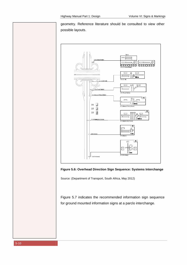
Highway Manual Part 1: Design Volume VI: Signs & Markings
5-10
geometry. Reference literature should be consulted to view other
possible layouts.
Figure 5.6: Overhead Direction Sign Sequence: Systems Interchange
Source: (Department of Transport, South Africa, May 2012)
Figure 5.7 indicates the recommended information sign sequence
for ground mounted information signs at a parclo interchange.
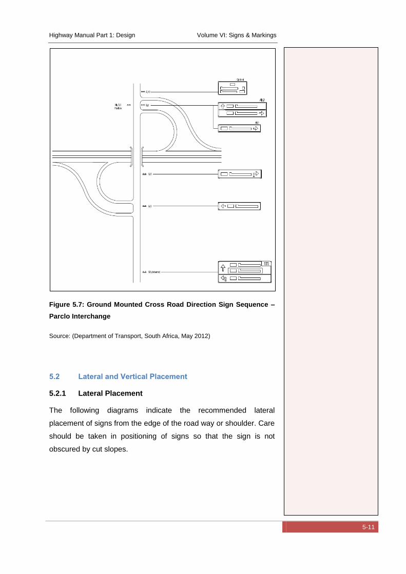
Highway Manual Part 1: Design Volume VI: Signs & Markings
5-11
Figure 5.7: Ground Mounted Cross Road Direction Sign Sequence –
Parclo Interchange
Source: (Department of Transport, South Africa, May 2012)
5.2 Lateral and Vertical Placement
5.2.1 Lateral Placement
The following diagrams indicate the recommended lateral
placement of signs from the edge of the road way or shoulder. Care
should be taken in positioning of signs so that the sign is not
obscured by cut slopes.
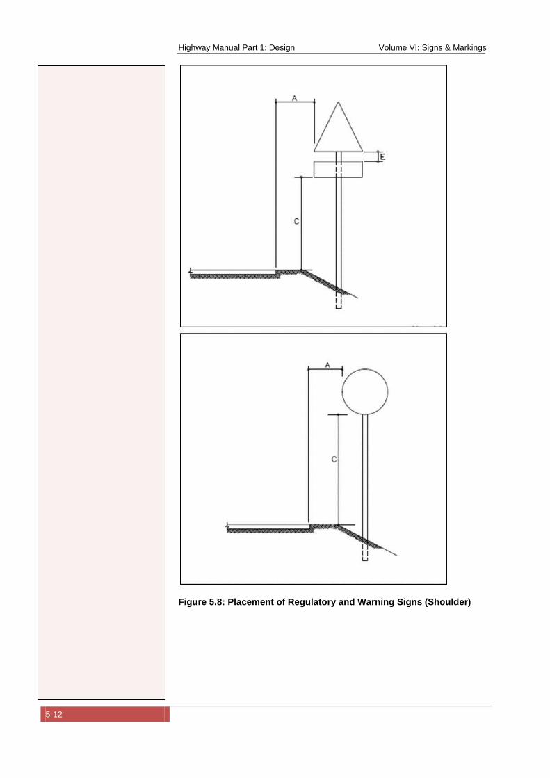
Highway Manual Part 1: Design Volume VI: Signs & Markings
5-12
Figure 5.8: Placement of Regulatory and Warning Signs (Shoulder)
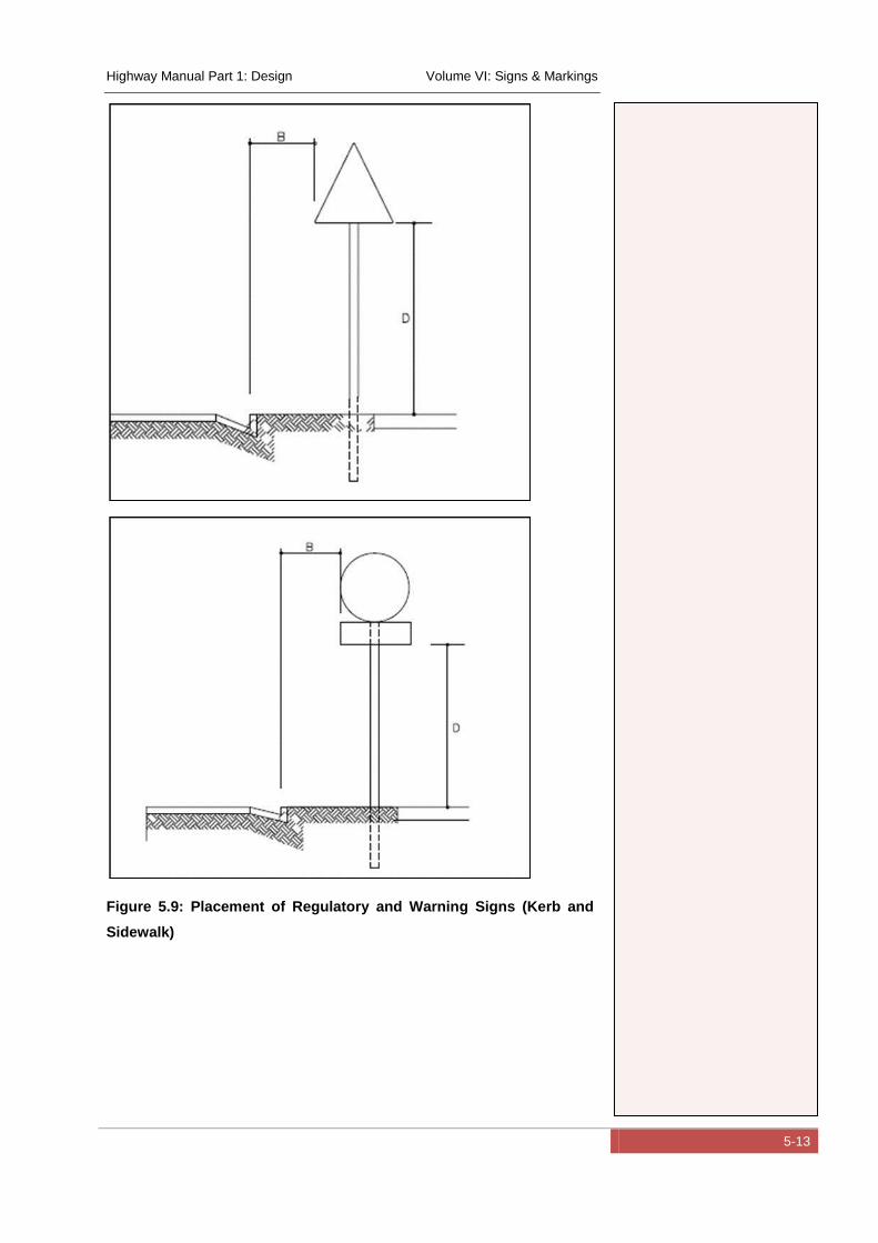
Highway Manual Part 1: Design Volume VI: Signs & Markings
5-13
Figure 5.9: Placement of Regulatory and Warning Signs (Kerb and
Sidewalk)
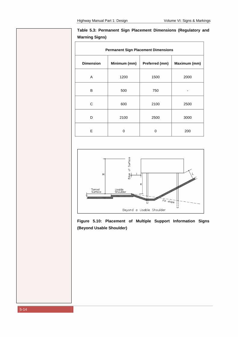
Highway Manual Part 1: Design Volume VI: Signs & Markings
5-14
Table 5.3: Permanent Sign Placement Dimensions (Regulatory and
Warning Signs)
Permanent Sign Placement Dimensions
Dimension Minimum (mm) Preferred (mm) Maximum (mm)
A 1200 1500 2000
B 500 750 -
C 600 2100 2500
D 2100 2500 3000
E 0 0 200
Figure 5.10: Placement of Multiple Support Information Signs
(Beyond Usable Shoulder)
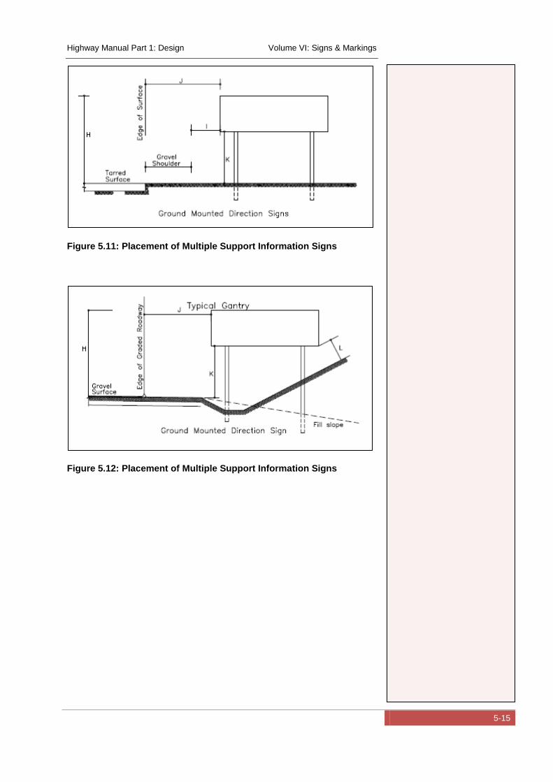
Highway Manual Part 1: Design Volume VI: Signs & Markings
5-15
Figure 5.11: Placement of Multiple Support Information Signs
Figure 5.12: Placement of Multiple Support Information Signs
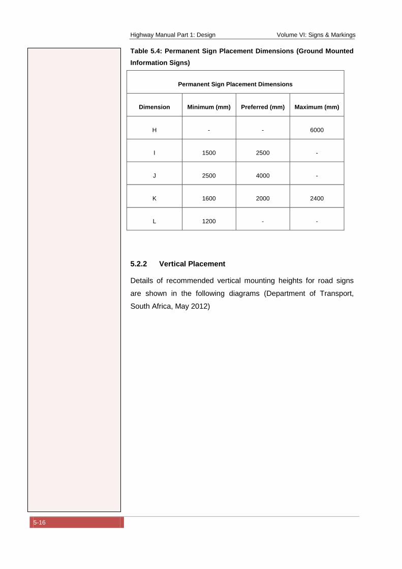
Highway Manual Part 1: Design Volume VI: Signs & Markings
5-16
Table 5.4: Permanent Sign Placement Dimensions (Ground Mounted
Information Signs)
Permanent Sign Placement Dimensions
Dimension Minimum (mm) Preferred (mm) Maximum (mm)
H - - 6000
I 1500 2500 -
J 2500 4000 -
K 1600 2000 2400
L 1200 - -
5.2.2 Vertical Placement
Details of recommended vertical mounting heights for road signs
are shown in the following diagrams (Department of Transport,
South Africa, May 2012)
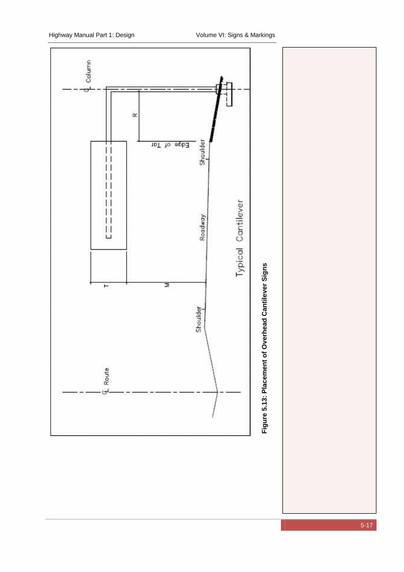
Highway Manual Part 1: Design Volume VI: Signs & Markings
5-17
Fig
ure
5.1
3:
Pla
cem
en
t o
f O
verh
ead
Can
tile
ve
r S
ign
s
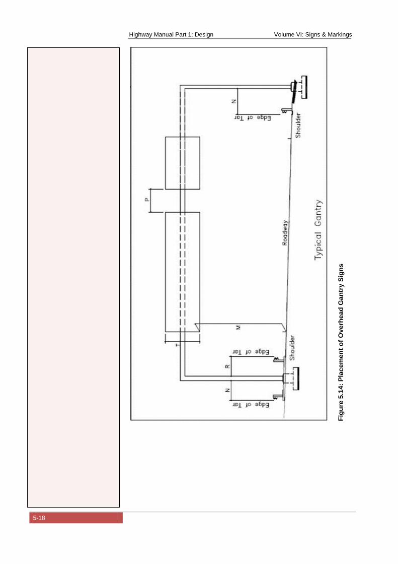
Highway Manual Part 1: Design Volume VI: Signs & Markings
5-18
Fig
ure
5.1
4:
Pla
cem
en
t o
f O
verh
ead
Gan
try
Sig
ns
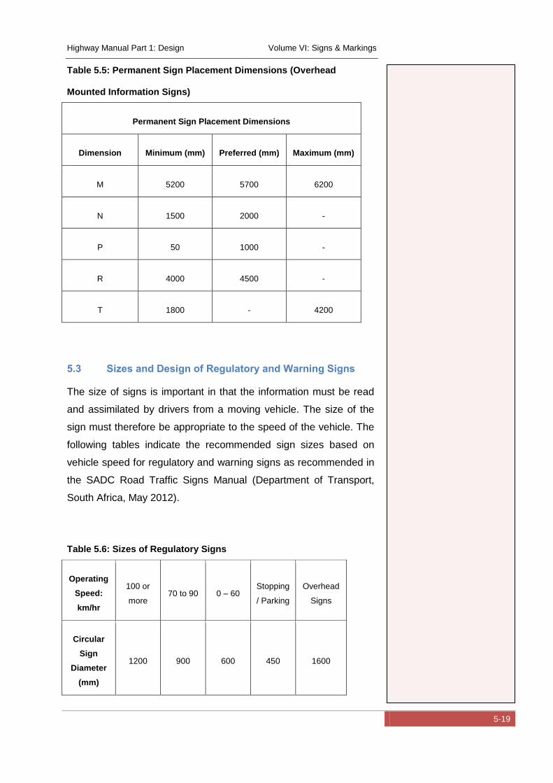
Highway Manual Part 1: Design Volume VI: Signs & Markings
5-19
Table 5.5: Permanent Sign Placement Dimensions (Overhead
Mounted Information Signs)
Permanent Sign Placement Dimensions
Dimension Minimum (mm) Preferred (mm) Maximum (mm)
M 5200 5700 6200
N 1500 2000 -
P 50 1000 -
R 4000 4500 -
T 1800 - 4200
5.3 Sizes and Design of Regulatory and Warning Signs
The size of signs is important in that the information must be read
and assimilated by drivers from a moving vehicle. The size of the
sign must therefore be appropriate to the speed of the vehicle. The
following tables indicate the recommended sign sizes based on
vehicle speed for regulatory and warning signs as recommended in
the SADC Road Traffic Signs Manual (Department of Transport,
South Africa, May 2012).
Table 5.6: Sizes of Regulatory Signs
Operating
Speed:
km/hr
100 or
more 70 to 90 0 – 60
Stopping
/ Parking
Overhead
Signs
Circular
Sign
Diameter
(mm)
1200 900 600 450 1600
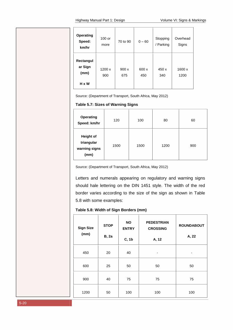
Highway Manual Part 1: Design Volume VI: Signs & Markings
5-20
Operating
Speed:
km/hr
100 or
more 70 to 90 0 – 60
Stopping
/ Parking
Overhead
Signs
Rectangul
ar Sign
(mm)
H x W
1200 x
900
900 x
675
600 x
450
450 x
340
1600 x
1200
Source: (Department of Transport, South Africa, May 2012)
Table 5.7: Sizes of Warning Signs
Operating
Speed: km/hr 120 100 80 60
Height of
triangular
warning signs
(mm)
1500 1500 1200 900
Source: (Department of Transport, South Africa, May 2012)
Letters and numerals appearing on regulatory and warning signs
should hale lettering on the DIN 1451 style. The width of the red
border varies according to the size of the sign as shown in Table
5.8 with some examples:
Table 5.8: Width of Sign Borders (mm)
Sign Size
(mm)
STOP
B, 2a
NO
ENTRY
C, 1b
PEDESTRIAN
CROSSING
A, 12
ROUNDABOUT
A, 22
450 20 40 - -
600 25 50 50 50
900 40 75 75 75
1200 50 100 100 100
Highway Manual Part 1: Design Volume VI: Signs & Markings
5-21
In order to achieve uniformity of sign design and layout, it is
recommended that suitable software be used to design the sign
layout (Refer to the following section - Design of Information Signs).
5.4 Design of Information Signs
The design of information signs is dependent on the standard letter
sizes, letter spacing used and the information content to be
included on the sign. Standards have been adopted by both the
United Kingdom Department of Transport Traffic Signs Manual (for
traffic signs in the UK) (UK-Department-of-Transport, 2004) and the
Southern African Development Community Road Traffic Signs
Manual (SADC RTSM) (Department of Transport, South Africa,
May 2012) (for traffic signs in South Africa and surrounding
countries).
Both the above references base the design of information signs on
a standard alphanumeric alphabet with variations for different types
of sign.
The UK standard has two versions: Transport Medium for white
characters on a green, blue, brown, red or black background, and
Transport Heavy for black characters on a white or yellow
background. To ensure the correct letter spacing, the letters are
placed on imaginary “tiles” with a fixed height and a variable width
depending on the character. Measurements are then taken from the
edges of the tiles and not the characters.
The size of an alphabet is specified in terms of its x-height. This is
the height of the lower case letter “x”, and is the same for both the
Transport Medium and Heavy alphabets. The unit of measurement
when designing a sign is the stroke width (sw) (which is one quarter
of the x-height) and is not necessarily equivalent to the width of any
given character. The dimensions for signs are then given in stroke
widths unless otherwise stated.
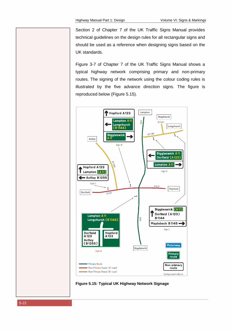
Highway Manual Part 1: Design Volume VI: Signs & Markings
5-22
Section 2 of Chapter 7 of the UK Traffic Signs Manual provides
technical guidelines on the design rules for all rectangular signs and
should be used as a reference when designing signs based on the
UK standards.
Figure 3-7 of Chapter 7 of the UK Traffic Signs Manual shows a
typical highway network comprising primary and non-primary
routes. The signing of the network using the colour coding rules is
illustrated by the five advance direction signs. The figure is
reproduced below (Figure 5.15).
Figure 5.15: Typical UK Highway Network Signage
Highway Manual Part 1: Design Volume VI: Signs & Markings
5-23
Source: (Figure 3-7 of UK Traffic Signs Manual) (UK-Department-of-Transport,
2004)
The design of traffic signs is relatively complex taking into
consideration the variations in letter sizes, colours, layouts etc. and
thus lends itself to the use of a computer programme that can
greatly simplify the task and aid standardisation of sign design. An
appropriate sign design computer programme has been sourced
from the internet at:
http://www.buchanancomputing.net/Brochures/SignPlot
According to the website “SignPlot is the UK’s leading traffic sign
software and includes state-of-the-art structural design. SignPlot is
the only system to fully automate the layout and spacing rules of
the Traffic Signs Regulations (TSRGD 2002) and UK Traffic Signs
Manual. SignPlot makes sign design quick and accurate for both
new and experienced designers”.
It is therefore recommended that should the UK traffic sign design
standard be adopted in Nigeria, suitable design software be
sourced and implemented to promote standardization of design.
The Southern African Development Community Road Traffic Signs
Manual (SADC RTSM) bases the layout and sizing of all guidance
signs on the dimensional characteristics of the DIN 1451 Part 2
letter style. DIN uppercase letters have a height of "7d", where "d"
is the stroke width of the letter. All arrows, symbols and fixed
spaces on the sign face are specified as multiples of "d". In this way
one sign face layout can serve as a design base for any size of
letter.
Chapter 4 of Volume 1 of the Southern African Development
Community Road Traffic Signs Manual (SADC RTSM)(Department
of Transport, South Africa, May 2012) provides guidelines for the
design of various types or information signs including elevated and
ground mounted signs.
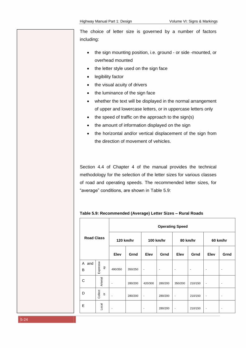
Highway Manual Part 1: Design Volume VI: Signs & Markings
5-24
The choice of letter size is governed by a number of factors
including:
the sign mounting position, i.e. ground - or side -mounted, or
overhead mounted
the letter style used on the sign face
legibility factor
the visual acuity of drivers
the luminance of the sign face
whether the text will be displayed in the normal arrangement
of upper and lowercase letters, or in uppercase letters only
the speed of traffic on the approach to the sign(s)
the amount of information displayed on the sign
the horizontal and/or vertical displacement of the sign from
the direction of movement of vehicles.
Section 4.4 of Chapter 4 of the manual provides the technical
methodology for the selection of the letter sizes for various classes
of road and operating speeds. The recommended letter sizes, for
“average” conditions, are shown in Table 5.9:
Table 5.9: Recommended (Average) Letter Sizes – Rural Roads
Road Class
Operating Speed
120 km/hr 100 km/hr 80 km/hr 60 km/hr
Elev Grnd Elev Grnd Elev Grnd Elev Grnd
A and
B
Expre
ssw
ay
490/350 350/250 - - - - - -
C
Art
eri
al
- 280/200 420/300 280/200 350/200 210/150 - -
D
Colle
ct
or
- 280/200 - 280/200 - 210/150 - -
E
Local
- - 280/200 - 210/150 - -
Highway Manual Part 1: Design Volume VI: Signs & Markings
5-25
490/350 = Uppercase/Lowercase
Elevated (Elev) / Ground (Grnd) refers to the location of the sign
Source: (Department of Transport, South Africa, May 2012)
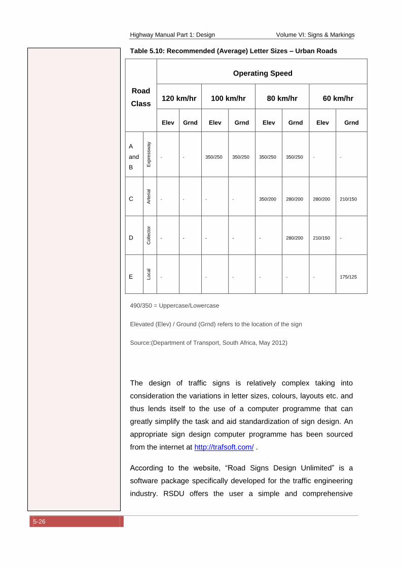
Highway Manual Part 1: Design Volume VI: Signs & Markings
5-26
Table 5.10: Recommended (Average) Letter Sizes – Urban Roads
Road
Class
Operating Speed
120 km/hr 100 km/hr 80 km/hr 60 km/hr
Elev Grnd Elev Grnd Elev Grnd Elev Grnd
A
and
B Expre
ssw
ay
- - 350/250 350/250 350/250 350/250 - -
C
Art
eri
al
- - - - 350/200 280/200 280/200 210/150
D
Colle
cto
r
- - - - - 280/200 210/150 -
E Local
- - - - - - 175/125
490/350 = Uppercase/Lowercase
Elevated (Elev) / Ground (Grnd) refers to the location of the sign
Source:(Department of Transport, South Africa, May 2012)
The design of traffic signs is relatively complex taking into
consideration the variations in letter sizes, colours, layouts etc. and
thus lends itself to the use of a computer programme that can
greatly simplify the task and aid standardization of sign design. An
appropriate sign design computer programme has been sourced
from the internet at http://trafsoft.com/ .
According to the website, “Road Signs Design Unlimited” is a
software package specifically developed for the traffic engineering
industry. RSDU offers the user a simple and comprehensive
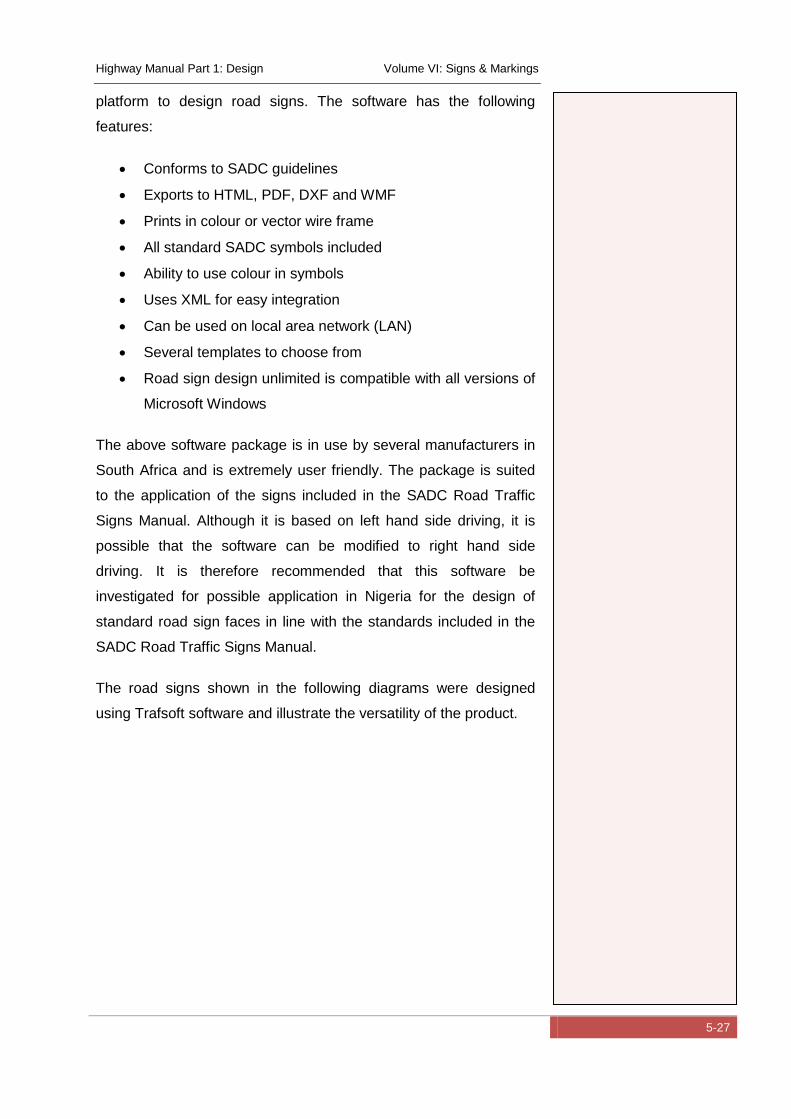
Highway Manual Part 1: Design Volume VI: Signs & Markings
5-27
platform to design road signs. The software has the following
features:
Conforms to SADC guidelines
Exports to HTML, PDF, DXF and WMF
Prints in colour or vector wire frame
All standard SADC symbols included
Ability to use colour in symbols
Uses XML for easy integration
Can be used on local area network (LAN)
Several templates to choose from
Road sign design unlimited is compatible with all versions of
Microsoft Windows
The above software package is in use by several manufacturers in
South Africa and is extremely user friendly. The package is suited
to the application of the signs included in the SADC Road Traffic
Signs Manual. Although it is based on left hand side driving, it is
possible that the software can be modified to right hand side
driving. It is therefore recommended that this software be
investigated for possible application in Nigeria for the design of
standard road sign faces in line with the standards included in the
SADC Road Traffic Signs Manual.
The road signs shown in the following diagrams were designed
using Trafsoft software and illustrate the versatility of the product.
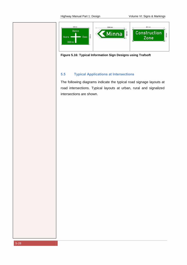
Highway Manual Part 1: Design Volume VI: Signs & Markings
5-28
Figure 5.16: Typical Information Sign Designs using Trafsoft
5.5 Typical Applications at Intersections
The following diagrams indicate the typical road signage layouts at
road intersections. Typical layouts at urban, rural and signalized
intersections are shown.
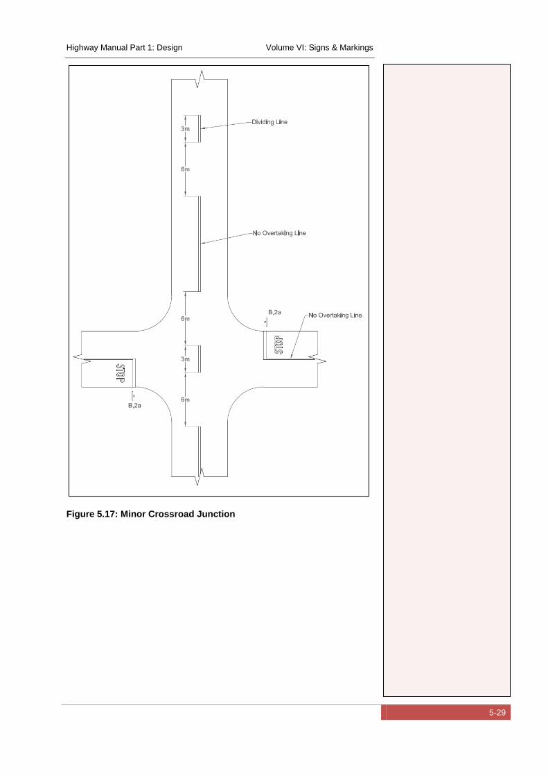
Highway Manual Part 1: Design Volume VI: Signs & Markings
5-29
Figure 5.17: Minor Crossroad Junction
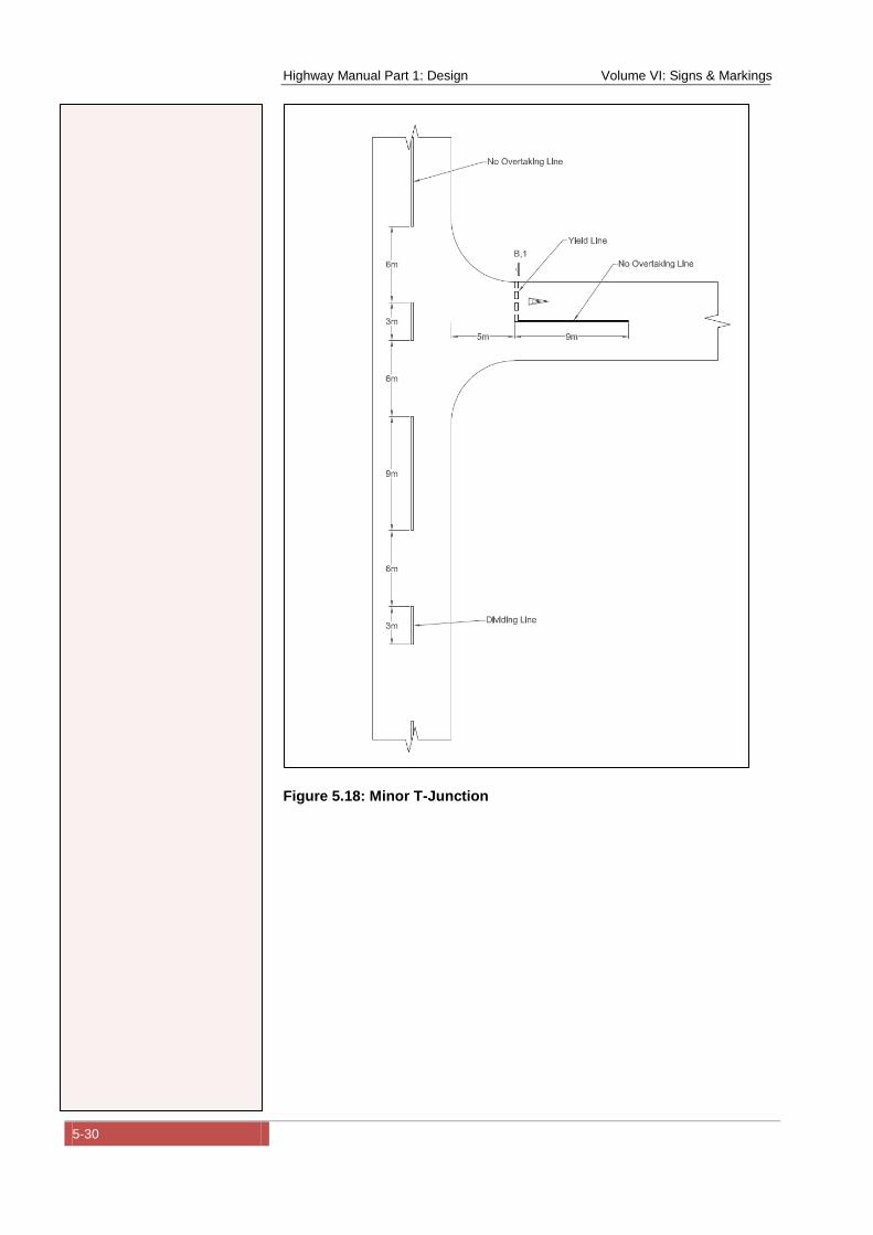
Highway Manual Part 1: Design Volume VI: Signs & Markings
5-30
Figure 5.18: Minor T-Junction
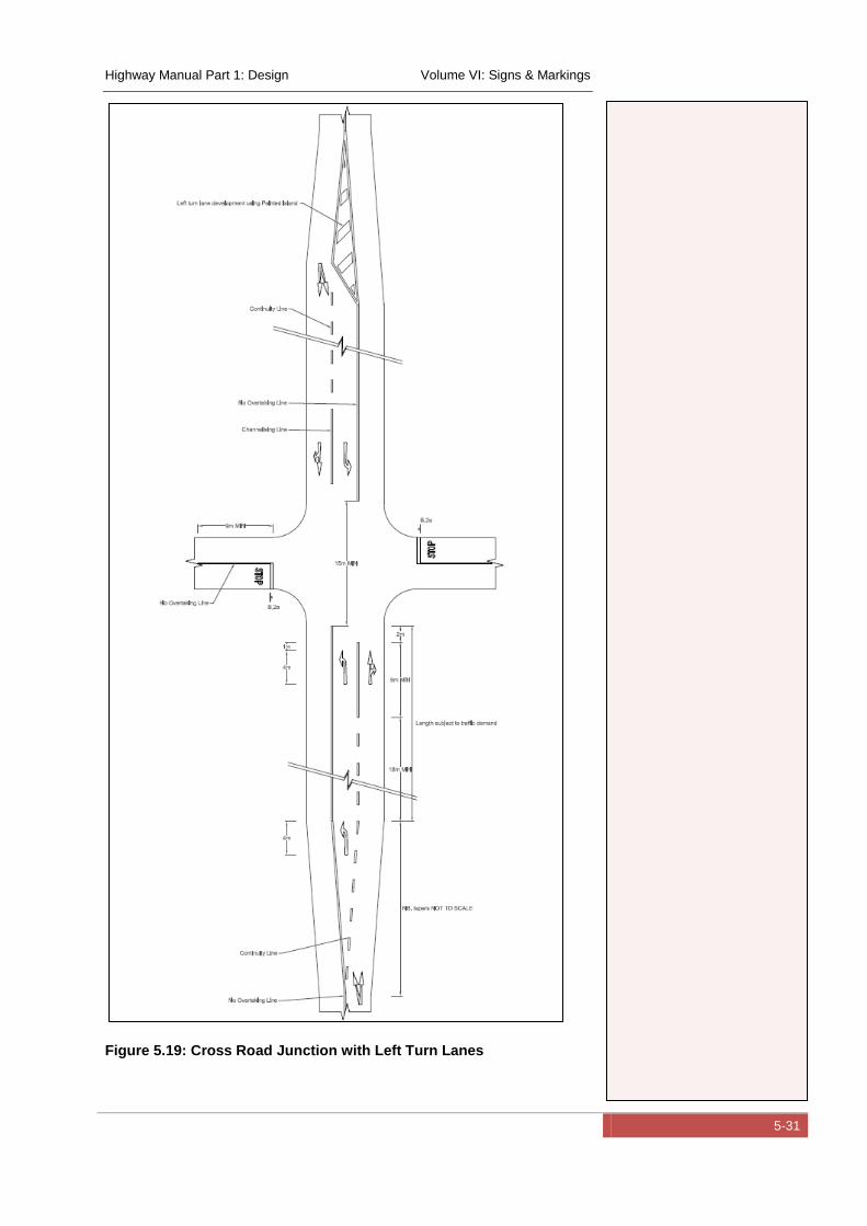
Highway Manual Part 1: Design Volume VI: Signs & Markings
5-31
Figure 5.19: Cross Road Junction with Left Turn Lanes
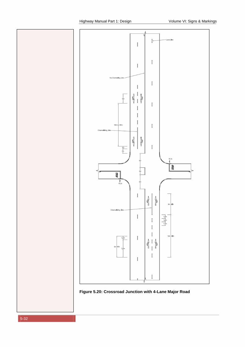
Highway Manual Part 1: Design Volume VI: Signs & Markings
5-32
Figure 5.20: Crossroad Junction with 4-Lane Major Road
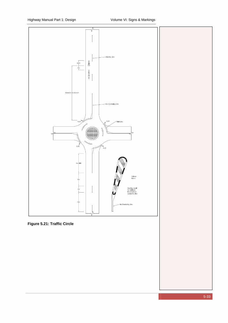
Highway Manual Part 1: Design Volume VI: Signs & Markings
5-33
Figure 5.21: Traffic Circle
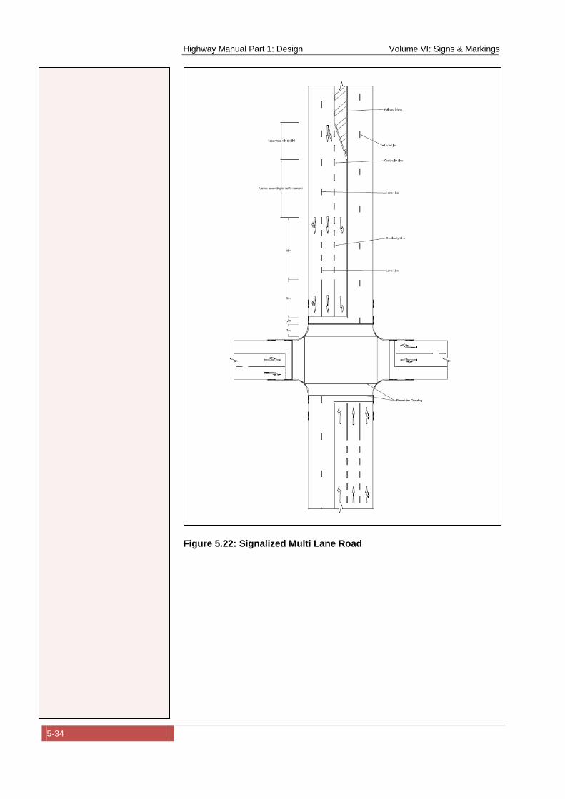
Highway Manual Part 1: Design Volume VI: Signs & Markings
5-34
Figure 5.22: Signalized Multi Lane Road
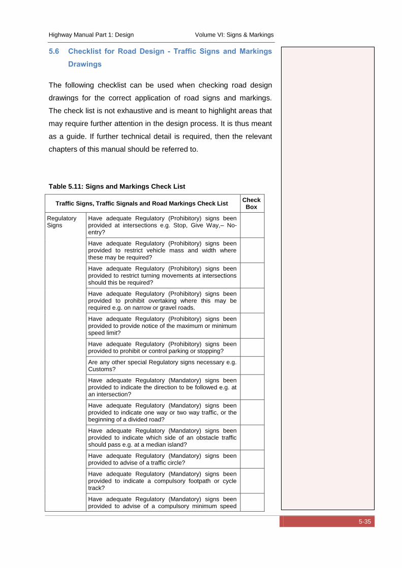
Highway Manual Part 1: Design Volume VI: Signs & Markings
5-35
5.6 Checklist for Road Design - Traffic Signs and Markings
Drawings
The following checklist can be used when checking road design
drawings for the correct application of road signs and markings.
The check list is not exhaustive and is meant to highlight areas that
may require further attention in the design process. It is thus meant
as a guide. If further technical detail is required, then the relevant
chapters of this manual should be referred to.
Table 5.11: Signs and Markings Check List
Traffic Signs, Traffic Signals and Road Markings Check List Check
Box
Regulatory Signs
Have adequate Regulatory (Prohibitory) signs been provided at intersections e.g. Stop, Give Way,– No-entry?
Have adequate Regulatory (Prohibitory) signs been provided to restrict vehicle mass and width where these may be required?
Have adequate Regulatory (Prohibitory) signs been provided to restrict turning movements at intersections should this be required?
Have adequate Regulatory (Prohibitory) signs been provided to prohibit overtaking where this may be required e.g. on narrow or gravel roads.
Have adequate Regulatory (Prohibitory) signs been provided to provide notice of the maximum or minimum speed limit?
Have adequate Regulatory (Prohibitory) signs been provided to prohibit or control parking or stopping?
Are any other special Regulatory signs necessary e.g. Customs?
Have adequate Regulatory (Mandatory) signs been provided to indicate the direction to be followed e.g. at an intersection?
Have adequate Regulatory (Mandatory) signs been provided to indicate one way or two way traffic, or the beginning of a divided road?
Have adequate Regulatory (Mandatory) signs been provided to indicate which side of an obstacle traffic should pass e.g. at a median island?
Have adequate Regulatory (Mandatory) signs been provided to advise of a traffic circle?
Have adequate Regulatory (Mandatory) signs been provided to indicate a compulsory footpath or cycle track?
Have adequate Regulatory (Mandatory) signs been provided to advise of a compulsory minimum speed
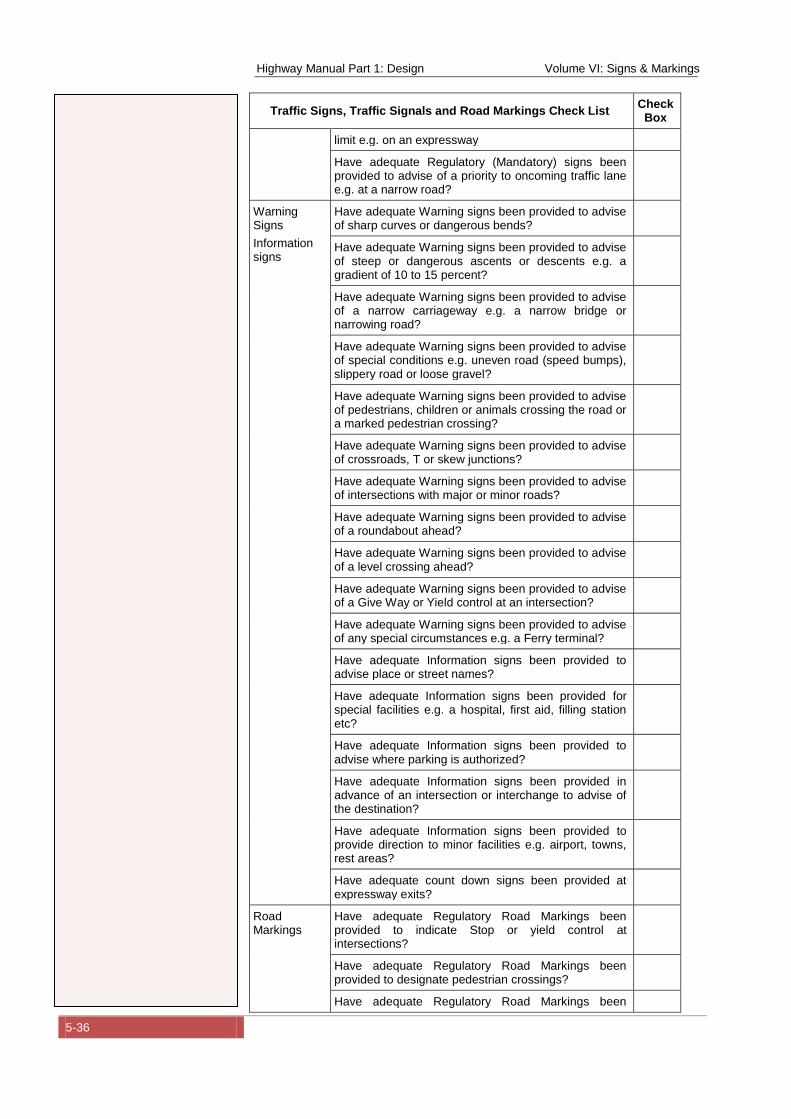
Highway Manual Part 1: Design Volume VI: Signs & Markings
5-36
Traffic Signs, Traffic Signals and Road Markings Check List Check
Box
limit e.g. on an expressway
Have adequate Regulatory (Mandatory) signs been provided to advise of a priority to oncoming traffic lane e.g. at a narrow road?
Warning Signs
Information signs
Have adequate Warning signs been provided to advise of sharp curves or dangerous bends?
Have adequate Warning signs been provided to advise of steep or dangerous ascents or descents e.g. a gradient of 10 to 15 percent?
Have adequate Warning signs been provided to advise of a narrow carriageway e.g. a narrow bridge or narrowing road?
Have adequate Warning signs been provided to advise of special conditions e.g. uneven road (speed bumps), slippery road or loose gravel?
Have adequate Warning signs been provided to advise of pedestrians, children or animals crossing the road or a marked pedestrian crossing?
Have adequate Warning signs been provided to advise of crossroads, T or skew junctions?
Have adequate Warning signs been provided to advise of intersections with major or minor roads?
Have adequate Warning signs been provided to advise of a roundabout ahead?
Have adequate Warning signs been provided to advise of a level crossing ahead?
Have adequate Warning signs been provided to advise of a Give Way or Yield control at an intersection?
Have adequate Warning signs been provided to advise of any special circumstances e.g. a Ferry terminal?
Have adequate Information signs been provided to advise place or street names?
Have adequate Information signs been provided for special facilities e.g. a hospital, first aid, filling station etc?
Have adequate Information signs been provided to advise where parking is authorized?
Have adequate Information signs been provided in advance of an intersection or interchange to advise of the destination?
Have adequate Information signs been provided to provide direction to minor facilities e.g. airport, towns, rest areas?
Have adequate count down signs been provided at expressway exits?
Road Markings
Have adequate Regulatory Road Markings been provided to indicate Stop or yield control at intersections?
Have adequate Regulatory Road Markings been provided to designate pedestrian crossings?
Have adequate Regulatory Road Markings been
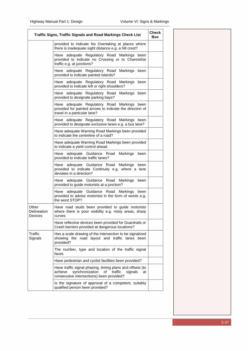
Highway Manual Part 1: Design Volume VI: Signs & Markings
5-37
Traffic Signs, Traffic Signals and Road Markings Check List
Check Box
provided to indicate No Overtaking at places where there is inadequate sight distance e.g. a hill crest?
Have adequate Regulatory Road Markings been provided to indicate no Crossing or to Channelize traffic e.g. at junctions?
Have adequate Regulatory Road Markings been provided to indicate painted islands?
Have adequate Regulatory Road Markings been provided to indicate left or right shoulders?
Have adequate Regulatory Road Markings been provided to designate parking bays?
Have adequate Regulatory Road Markings been provided for painted arrows to indicate the direction of travel in a particular lane?
Have adequate Regulatory Road Markings been provided to designate exclusive lanes e.g. a bus lane?
Have adequate Warning Road Markings been provided to indicate the centreline of a road?
Have adequate Warning Road Markings been provided to indicate a yield control ahead.
Have adequate Guidance Road Markings been provided to indicate traffic lanes?
Have adequate Guidance Road Markings been provided to indicate Continuity e.g. where a lane deviates in a direction?
Have adequate Guidance Road Markings been provided to guide motorists at a junction?
Have adequate Guidance Road Markings been provided to advise motorists in the form of words e.g. the word STOP?
Other Delineation Devices
Have road studs been provided to guide motorists where there is poor visibility e.g. misty areas, sharp curves
Have reflective devices been provided for Guardrails or Crash barriers provided at dangerous locations?
Traffic Signals
Has a scale drawing of the intersection to be signalized showing the road layout and traffic lanes been provided?
The number, type and location of the traffic signal faces
Have pedestrian and cyclist facilities been provided?
Have traffic signal phasing, timing plans and offsets (to achieve synchronization of traffic signals at consecutive intersections) been provided?
Is the signature of approval of a competent, suitably qualified person been provided?

Highway Manual Part 1: Design Volume VI: Signs & Markings
6-1
6 Materials and Installation
6.1 Traffic Sign Materials
Traffic signs should generally be retro-reflective to aid visibility at
night and in poor weather conditions. This is particularly true for the
message on the signs and in some cases the background of the
sign as well: although cost may be a factor. Retro-reflective
materials are available in many grades and quality. In the Southern
African Development Community Road Traffic Signs Manual
(Department of Transport, South Africa, May 2012), Classes I, II or
III materials are specified according to the South African National
Standard SANS 1519. The British Standard No 873, The
Construction of Road Traffic Signs and Internally Illuminated
Bollards may also be referenced in this regard. The Classes I, II or
III have an increasing coefficient of retro-reflection.
According to SANS “Retro-reflective sheeting consists of a smooth ,
flat, transparent or translucent film that has retro-reflective elements
below the surface forming an optical reflecting system that has a
non exposed lens”. This can be achieved by incorporating glass
beads or prisms.
It is recommended that all signs be retro-reflective except as
follows:
Prohibitory regulatory signs – black symbols may be “black
semi-matt”
Mandatory regulatory signs - the white arrows can be “white
semi-matt”
Direction signs on expressways should have a higher reflectivity
e.g. Class II or III due to the higher speeds.
The sign board material (metal sheeting) is specified at the
discretion of the road authority. If the sign is to be fully coated with
retro-reflective materials, then the material should have a life
Highway Manual Part 1: Design Volume VI: Signs & Markings
6-2
expectancy of at least the same as the retro-reflective material
(normally seven to 10 years).
Typically an epoxy coated galvanized steel sheeting can be used
which is pre-painted and baked, resulting in a flat, durable, vinyl
receptive surface that has UV resistant properties.
In areas where theft of large direction signs (usually information
signs) is a problem, the signs can be manufactured in panels, as
opposed to one large sheet. The panels can be affixed separately.
This discourages the signs from being used for the construction of
informal houses for example. Another example is to perforate the
signs with drill holes. This renders the sheeting useless for any
other use.
6.2 Road Marking Materials
Road markings are defined as markings applied to the road surface
and can be in the form of paint, plastic or sheet.
The application and life of a road marking is markedly affected by
the texture of the road surface and how it is prepared. Paints may
be applied in a range of thicknesses and are quick drying. The
thickness depends on the amount of traffic and the required
durability (between 0.2 and 0.5 millimetres thick). Generally paints
can be either suitable for spray application or for general brush
application. They can also be supplied as suitable for the
subsequent application of glass beads to improve reflectivity. The
glass beads must be applied before the paint dries and are applied
not less than 0.34 kg/m2 of marking.
Markings in the form of a sheet or tape that is glued to the road
surface can be used. Due to the cost their application is usually
limited to small areas or to pre-formed symbols e.g. a STOP
marking.
Factors that can be included in a specification for road marking
include:
Highway Manual Part 1: Design Volume VI: Signs & Markings
6-3
Colour
Luminance factor
Coefficient of reflection
Skid resistance
The durability of new markings is affected by the time a new road
surface has had to “cure” and the application rate used for the road
marking material. Usually the curing time for a new road surface is
catered for by using two applications of the road markings at closely
spaced applications.
6.3 Installation of Road Signs
There are a number of factors that affect the design of a support
structure needed for a traffic sign. These include the following:
Weather and climate e.g. wind, rain
The location e.g. urban, rural
Road class, speed
Road side conditions e.g. cut, fill slopes
Clearances – vertical and lateral
Safety
Vandalism
Regulatory and warning signs are considered to be small signs.
These signs are normally ground mounted on a single pole. This
can either be a free standing pole or an existing pole e.g. a light
pole. The signs may require horizontal stiffening in the form of two
horizontal struts at the back. Larger signs may require two supports
depending on wind conditions.
Small Information signs (1.5 to 8m2) normally require two or three
supports without diagonal bracing. These signs require back plate
and framing to improve stiffness. This additional weight and wind
loads must be planned for.
Highway Manual Part 1: Design Volume VI: Signs & Markings
6-4
Large ground mounted information signs (8.0 to over 20m2) and
these normally require three or four supporting poles with diagonal
bracing. These signs require a back place and extensive framing
support. Due to the additional weight these signs require more
extensive foundations and fastening brackets.
The above signs could also be erected on overhead structures on
roads carrying higher volumes of traffic with more than two lanes
per direction, and where higher visibility or lane specific messages
are required. The support structures for these signs require an
extensive back plate, framing and reinforced concrete foundations.
The support structures may comprise simple to heavy portal
structures, cantilever structures or existing bridges.
Supporting structures for signs range from timber poles, steel
tubes, rolled sections or special fabricated supports. For the larger
overhead structures a special structural design may be required
and in other applications a standard support structure design may
be used.
The design of sign support structures should take into consideration
the following:
a. Loadings including the effect of wind, live and impact loads
in excess of the structures dead load:
Signs should be designed to resist vibration in the wind that can
lead to metal fatigue. Live loads should be considered e.g.
walkways on large structures, and the effects of a vehicle
impact. Signs located close to the carriageway should be
designed to be yielding or of a breakaway design in order to
reduce the damage and injury in a vehicle crash e.g. allow the
vehicle to pass over the sign or underneath the sign.
b. Ability to withstand vandalism:
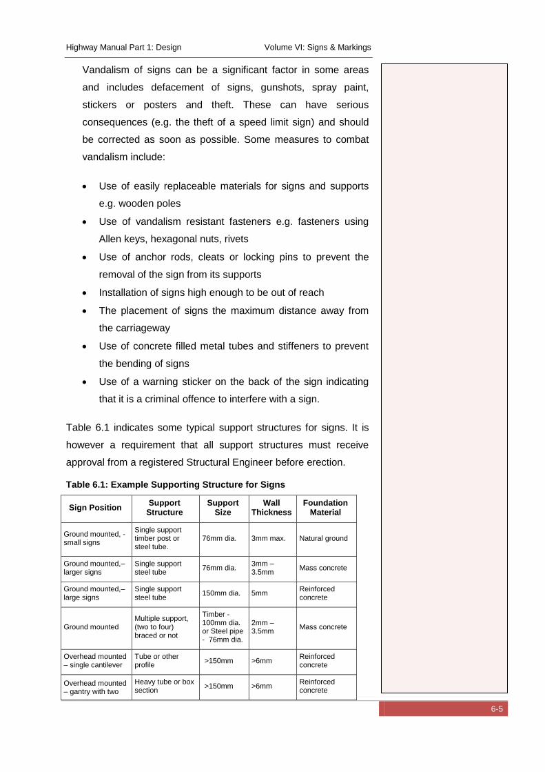
Highway Manual Part 1: Design Volume VI: Signs & Markings
6-5
Vandalism of signs can be a significant factor in some areas
and includes defacement of signs, gunshots, spray paint,
stickers or posters and theft. These can have serious
consequences (e.g. the theft of a speed limit sign) and should
be corrected as soon as possible. Some measures to combat
vandalism include:
Use of easily replaceable materials for signs and supports
e.g. wooden poles
Use of vandalism resistant fasteners e.g. fasteners using
Allen keys, hexagonal nuts, rivets
Use of anchor rods, cleats or locking pins to prevent the
removal of the sign from its supports
Installation of signs high enough to be out of reach
The placement of signs the maximum distance away from
the carriageway
Use of concrete filled metal tubes and stiffeners to prevent
the bending of signs
Use of a warning sticker on the back of the sign indicating
that it is a criminal offence to interfere with a sign.
Table 6.1 indicates some typical support structures for signs. It is
however a requirement that all support structures must receive
approval from a registered Structural Engineer before erection.
Table 6.1: Example Supporting Structure for Signs
Sign Position Support
Structure Support
Size Wall
Thickness Foundation
Material
Ground mounted, - small signs
Single support timber post or steel tube.
76mm dia. 3mm max. Natural ground
Ground mounted,– larger signs
Single support steel tube
76mm dia. 3mm – 3.5mm
Mass concrete
Ground mounted,– large signs
Single support steel tube
150mm dia. 5mm Reinforced concrete
Ground mounted Multiple support, (two to four) braced or not
Timber - 100mm dia. or Steel pipe - 76mm dia.
2mm – 3.5mm
Mass concrete
Overhead mounted – single cantilever
Tube or other profile
>150mm >6mm Reinforced concrete
Overhead mounted – gantry with two
Heavy tube or box section
>150mm >6mm Reinforced concrete
Highway Manual Part 1: Design Volume VI: Signs & Markings
6-6
legs
Signs may also be erected on reinforced, precast concrete posts or
reinforced concrete structure as specified by a Structural Engineer.
The use of light weight reinforced concrete slabs for a sign face has
also been proposed in Nigeria to combat vandalism. Additional
research is required into this proposal for a final design to be
selected.
Highway Manual Part 1: Design Volume VI: Signs & Markings
7-1
7 Bibliography
Commission, F. R. (2008). Nigeria Highway Code. Abuja: Detailwoks.
Corps, F. R. (2012). Nigeria Road Safety Strategy. Abuja.
Department of Transport, South Africa. (May 2012). SADC Road Traffic Signs Manual - Digitised Version.
Institute, T. T. (March 2008). Traffic Signal Warrants - Guidelines for conduction a traffic signal warrant analysis.
Open-Street-Map. (n.d.). http://wiki.openstreetmap.org/wiki/WikiProject_Nigeria.
UK-Department-of-Transport. (2004). Traffic Signs Manual.
United-Nations. (2006). Convention on Road Signs.
Wikipedia. (n.d.). Wikipedia. Retrieved from http://en.wikipedia.org/.
Related Documents