2326 IEEE TRANSACTIONS ON POWER DELIVERY, VOL. 28, NO. 4, OCTOBER 2013 Fault Classification and Faulted Phase Selection Based on the Symmetrical Components of Reactive Power for Single-Circuit Transmission Lines Behnam Mahamedi and Jian Guo Zhu, Senior Member, IEEE Abstract—This paper presents a fault classification method with faulted phase selection action for single-circuit transmission lines which is based on the symmetrical components of reactive power. The proposed method does not need any threshold to operate and it is thus a setting-free method which is an exceptional attribute for a protective function. The evaluation of different fault cases reveals the capability of the proposed method. Index Terms—Fault classification, faulted phase selection, sym- metrical components of reactive power, transmission lines. I. INTRODUCTION I N transmission-line protection, it is required to classify faults and select faulted phase(s) to trigger the proper distance element without which distance relays will fail. More- over, these functions are essential for single-pole tripping and auto-reclosing action. Up till now, several approaches to fault classification and faulted phase selection have been proposed by researchers. Lin et al. [1] put forward a faulted phase selection method based on superimposed positive- and negative-sequence currents com- bined with the correlation theory, which was used to calculate the angle between two signals. It can be found out that the method is highly vulnerable to fault resistance. Benmuoyal and Mahseredjian [2] presented an interesting method to determine the direction of faults and to select the faulted phases based on the ratio of differential superimposed voltage (e.g. ) to differential superimposed current (e.g. ). However, determining the thresholds required for the method is not an easy task. Adu [3] proposed a fault classification technique based on the phase angles between superimposed positive- and negative-se- quence currents. The method also used the relative magnitudes of the zero- and negative-sequence currents with respect to the positive-sequence current to differentiate between the grounded Manuscript received November 06, 2012; revised March 06, 2013 and April 22, 2013; accepted May 27, 2013. Date of publication August 06, 2013; date of current version September 19, 2013. Paper no. TPWRD-01160-2012. B. Mahamedi was with the School of Electrical, Mechanical and Mechatronic Systems, University of Technology Sydney, Ultimo, NSW 2007, Australia. He is now with the Iran Grid Management Company, Tehran IR-15175-648, Iran (e-mail: [email protected]). J. G. Zhu is with the School of Electrical, Mechanical and Mechatronic Sys- tems, University of Technology Sydney, Ultimo NSW 2007, Australia (e-mail: [email protected]). Digital Object Identifier 10.1109/TPWRD.2013.2265711 and ungrounded faults. Several criteria should be checked to ac- complish fault classification task. Moreover, the method failed for non-zero fault resistance. As a remedy, the author proposed a modification based on simulation results. It is known that judg- ment based on only simulation studies cannot assure the validity of a method in all possible cases. Alongside classification and selection based on steady-state values, transients-based classification and selection were devel- oped by introducing the digital signal processing (DSP) [4]. These methods benefit from the specific transient patterns of electrical signals after fault inception. The success rate of these methods, however, highly depends on the sampling frequency [5]. Using fault transients, Silva et al. [6] presented an applica- tion of Haar wavelet transform for fault classification in trans- mission lines. Faulted phase selection was carried out by cal- culating the energy of detail coefficients of the phase currents. By analyzing the smooth coefficients of the neutral current, the grounded faults were distinguished from the ungrounded ones. The performance of the method is jeopardized due to fault inci- dent angle variations. Dong et al. [7] proposed another algorithm of fault classi- fication and faulted phase selection based on the initial current traveling wave. The characteristics of various faults were inves- tigated on the basis of the Karenbauer transform. The sampling frequency adopted for evaluation studies was chosen 400 kHz which is much more than common sampling frequency used in numerical relays [8]. Typically, high sampling frequency is the main disadvantage of transient-based methods. Jamehbozorg and Shahrtash [9] and [10] put forward a de- cision-tree-based method for fault classification in double-cir- cuit and single-circuit transmission lines by using the traveling waves initiated by the fault and applying half-cycle discrete Fourier transform (HCDFT). It is required to calculate up to the 19th harmonic component which results in a great amount of data and consequently the computing burden will significantly increase. In this paper, a new steady-state-based approach to fault classification and faulted phase selection for single-circuit transmission lines is proposed by using the sequential reactive power components. The reactive power formed by the positive- and negative-sequence components (Q12) is used to determine phase-to-phase faults and the phases involved in this type of faults. To distinguish the single-phase-to-earth faults from double-phase-to-earth ones, the ratio of the zero-sequence reac- tive power to the negative-sequence reactive power measured 0885-8977 © 2013 IEEE

Fault Classification and Fault Phase Selection
Oct 22, 2015
Welcome message from author
This document is posted to help you gain knowledge. Please leave a comment to let me know what you think about it! Share it to your friends and learn new things together.
Transcript
2326 IEEE TRANSACTIONS ON POWER DELIVERY, VOL. 28, NO. 4, OCTOBER 2013
Fault Classification and Faulted Phase SelectionBased on the Symmetrical Components of ReactivePower for Single-Circuit Transmission Lines
Behnam Mahamedi and Jian Guo Zhu, Senior Member, IEEE
Abstract—This paper presents a fault classification method withfaulted phase selection action for single-circuit transmission lineswhich is based on the symmetrical components of reactive power.The proposedmethod does not need any threshold to operate and itis thus a setting-free method which is an exceptional attribute for aprotective function. The evaluation of different fault cases revealsthe capability of the proposed method.
Index Terms—Fault classification, faulted phase selection, sym-metrical components of reactive power, transmission lines.
I. INTRODUCTION
I N transmission-line protection, it is required to classifyfaults and select faulted phase(s) to trigger the proper
distance element without which distance relays will fail. More-over, these functions are essential for single-pole tripping andauto-reclosing action.Up till now, several approaches to fault classification and
faulted phase selection have been proposed by researchers. Linet al. [1] put forward a faulted phase selection method basedon superimposed positive- and negative-sequence currents com-bined with the correlation theory, which was used to calculatethe angle between two signals. It can be found out that themethod is highly vulnerable to fault resistance.Benmuoyal and Mahseredjian [2] presented an interesting
method to determine the direction of faults and to select thefaulted phases based on the ratio of differential superimposedvoltage (e.g. ) to differential superimposed current (e.g.
). However, determining the thresholds required for themethod is not an easy task.Adu [3] proposed a fault classification technique based on the
phase angles between superimposed positive- and negative-se-quence currents. The method also used the relative magnitudesof the zero- and negative-sequence currents with respect to thepositive-sequence current to differentiate between the grounded
Manuscript received November 06, 2012; revised March 06, 2013 and April22, 2013; accepted May 27, 2013. Date of publication August 06, 2013; date ofcurrent version September 19, 2013. Paper no. TPWRD-01160-2012.B. Mahamedi was with the School of Electrical, Mechanical andMechatronic
Systems, University of Technology Sydney, Ultimo, NSW 2007, Australia. Heis now with the Iran Grid Management Company, Tehran IR-15175-648, Iran(e-mail: [email protected]).J. G. Zhu is with the School of Electrical, Mechanical and Mechatronic Sys-
tems, University of Technology Sydney, Ultimo NSW 2007, Australia (e-mail:[email protected]).Digital Object Identifier 10.1109/TPWRD.2013.2265711
and ungrounded faults. Several criteria should be checked to ac-complish fault classification task. Moreover, the method failedfor non-zero fault resistance. As a remedy, the author proposed amodification based on simulation results. It is known that judg-ment based on only simulation studies cannot assure the validityof a method in all possible cases.Alongside classification and selection based on steady-state
values, transients-based classification and selection were devel-oped by introducing the digital signal processing (DSP) [4].These methods benefit from the specific transient patterns ofelectrical signals after fault inception. The success rate of thesemethods, however, highly depends on the sampling frequency[5].Using fault transients, Silva et al. [6] presented an applica-
tion of Haar wavelet transform for fault classification in trans-mission lines. Faulted phase selection was carried out by cal-culating the energy of detail coefficients of the phase currents.By analyzing the smooth coefficients of the neutral current, thegrounded faults were distinguished from the ungrounded ones.The performance of the method is jeopardized due to fault inci-dent angle variations.Dong et al. [7] proposed another algorithm of fault classi-
fication and faulted phase selection based on the initial currenttraveling wave. The characteristics of various faults were inves-tigated on the basis of the Karenbauer transform. The samplingfrequency adopted for evaluation studies was chosen 400 kHzwhich is much more than common sampling frequency used innumerical relays [8]. Typically, high sampling frequency is themain disadvantage of transient-based methods.Jamehbozorg and Shahrtash [9] and [10] put forward a de-
cision-tree-based method for fault classification in double-cir-cuit and single-circuit transmission lines by using the travelingwaves initiated by the fault and applying half-cycle discreteFourier transform (HCDFT). It is required to calculate up to the19th harmonic component which results in a great amount ofdata and consequently the computing burden will significantlyincrease.In this paper, a new steady-state-based approach to fault
classification and faulted phase selection for single-circuittransmission lines is proposed by using the sequential reactivepower components. The reactive power formed by the positive-and negative-sequence components (Q12) is used to determinephase-to-phase faults and the phases involved in this type offaults. To distinguish the single-phase-to-earth faults fromdouble-phase-to-earth ones, the ratio of the zero-sequence reac-tive power to the negative-sequence reactive power measured
0885-8977 © 2013 IEEE
MAHAMEDI AND ZHU: FAULT CLASSIFICATION AND FAULTED PHASE SELECTION 2327
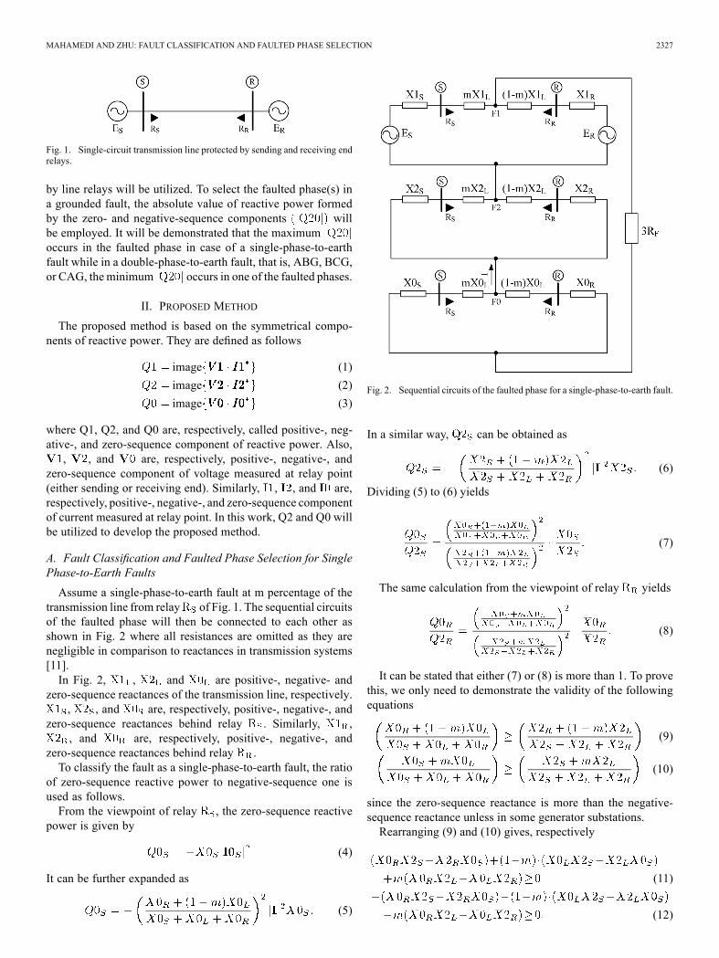
Fig. 1. Single-circuit transmission line protected by sending and receiving endrelays.
by line relays will be utilized. To select the faulted phase(s) ina grounded fault, the absolute value of reactive power formedby the zero- and negative-sequence components willbe employed. It will be demonstrated that the maximumoccurs in the faulted phase in case of a single-phase-to-earthfault while in a double-phase-to-earth fault, that is, ABG, BCG,or CAG, the minimum occurs in one of the faulted phases.
II. PROPOSED METHOD
The proposed method is based on the symmetrical compo-nents of reactive power. They are defined as follows
image (1)
image (2)
image (3)
where Q1, Q2, and Q0 are, respectively, called positive-, neg-ative-, and zero-sequence component of reactive power. Also,, , and are, respectively, positive-, negative-, and
zero-sequence component of voltage measured at relay point(either sending or receiving end). Similarly, , , and are,respectively, positive-, negative-, and zero-sequence componentof current measured at relay point. In this work, Q2 and Q0 willbe utilized to develop the proposed method.
A. Fault Classification and Faulted Phase Selection for SinglePhase-to-Earth Faults
Assume a single-phase-to-earth fault at m percentage of thetransmission line from relay of Fig. 1. The sequential circuitsof the faulted phase will then be connected to each other asshown in Fig. 2 where all resistances are omitted as they arenegligible in comparison to reactances in transmission systems[11].In Fig. 2, , and are positive-, negative- and
zero-sequence reactances of the transmission line, respectively., , and are, respectively, positive-, negative-, and
zero-sequence reactances behind relay . Similarly, ,, and are, respectively, positive-, negative-, and
zero-sequence reactances behind relay .To classify the fault as a single-phase-to-earth fault, the ratio
of zero-sequence reactive power to negative-sequence one isused as follows.From the viewpoint of relay , the zero-sequence reactive
power is given by
(4)
It can be further expanded as
(5)
Fig. 2. Sequential circuits of the faulted phase for a single-phase-to-earth fault.
In a similar way, can be obtained as
(6)
Dividing (5) to (6) yields
(7)
The same calculation from the viewpoint of relay yields
(8)
It can be stated that either (7) or (8) is more than 1. To provethis, we only need to demonstrate the validity of the followingequations
(9)
(10)
since the zero-sequence reactance is more than the negative-sequence reactance unless in some generator substations.Rearranging (9) and (10) gives, respectively
(11)
(12)
2328 IEEE TRANSACTIONS ON POWER DELIVERY, VOL. 28, NO. 4, OCTOBER 2013
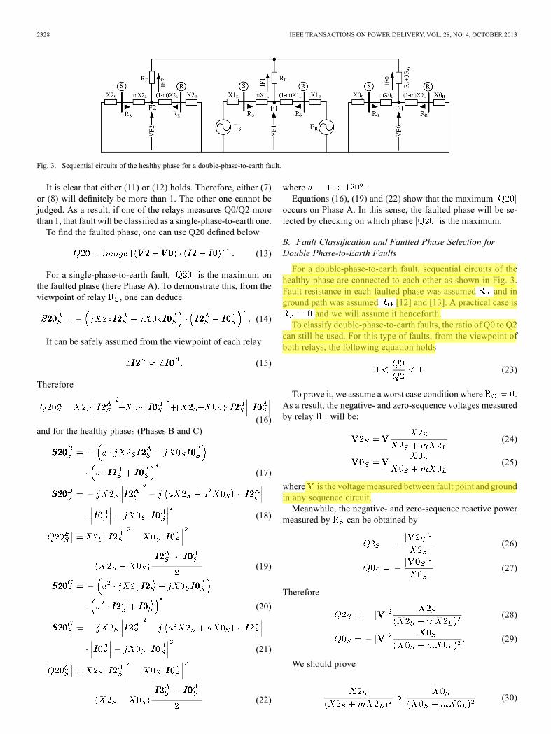
Fig. 3. Sequential circuits of the healthy phase for a double-phase-to-earth fault.
It is clear that either (11) or (12) holds. Therefore, either (7)or (8) will definitely be more than 1. The other one cannot bejudged. As a result, if one of the relays measures Q0/Q2 morethan 1, that fault will be classified as a single-phase-to-earth one.To find the faulted phase, one can use Q20 defined below
(13)
For a single-phase-to-earth fault, is the maximum onthe faulted phase (here Phase A). To demonstrate this, from theviewpoint of relay , one can deduce
(14)
It can be safely assumed from the viewpoint of each relay
(15)
Therefore
(16)and for the healthy phases (Phases B and C)
(17)
(18)
(19)
(20)
(21)
(22)
where .Equations (16), (19) and (22) show that the maximum
occurs on Phase A. In this sense, the faulted phase will be se-lected by checking on which phase is the maximum.
B. Fault Classification and Faulted Phase Selection forDouble Phase-to-Earth Faults
For a double-phase-to-earth fault, sequential circuits of thehealthy phase are connected to each other as shown in Fig. 3.Fault resistance in each faulted phase was assumed and inground path was assumed [12] and [13]. A practical case is
and we will assume it henceforth.To classify double-phase-to-earth faults, the ratio of Q0 to Q2
can still be used. For this type of faults, from the viewpoint ofboth relays, the following equation holds
(23)
To prove it, we assume a worst case condition where .As a result, the negative- and zero-sequence voltages measuredby relay will be:
(24)
(25)
where is the voltagemeasured between fault point and groundin any sequence circuit.Meanwhile, the negative- and zero-sequence reactive power
measured by can be obtained by
(26)
(27)
Therefore
(28)
(29)
We should prove
(30)
Usama Ashfaq
Highlight
Usama Ashfaq
Highlight
MAHAMEDI AND ZHU: FAULT CLASSIFICATION AND FAULTED PHASE SELECTION 2329
or equivalently
(31)
As the zero-sequence impedances were assumed more thanthe negative-sequence ones, as a sufficient condition, we need
(32)
or
(33)
Since X0/X2 of a line is always equal or more than that of asource it can then be concluded
(34)
Correspondingly from the viewpoint of relay we have
(35)
With this justification in mind, one can find that for ,(34) and (35) still hold from the viewpoint of both relays.To select the faulted phases, Q20 is utilized. If the phase angle
of voltage at point F1 is assumed as a reference, the phase angleof will be and that of will fall betweento 0 which is here represented by (note that and
). Assuming Phase C as the healthy phase, it can beworked out as
(36)
and for the faulted phases (Phases A and B):
(37)
(38)
As the following inequalities are held for
(39)
(40)
one can find that is the minimum on Phase B in the ABGfaults. Similarly, for the BCG and CAG faults, is theminimum on Phases C and A, respectively. The faulted phaseswill thus be identified by checking on which phase is theminimum.
C. Fault Classification and Faulted Phase Selection forPhase-to-Phase Faults
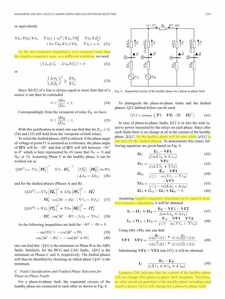
For a phase-to-phase fault, the sequential circuits of thehealthy phase are connected to each other as shown in Fig. 4.
Fig. 4. Sequential circuits of the healthy phase for a phase-to-phase fault.
To distinguish the phase-to-phase faults and the faultedphases, Q12 defined below can be used
(41)
In case of phase-to-phase faults, Q12 is in fact the total re-active power measured by the relays on each phase. Since aftersuch faults there is no change at all in the current of the healthyphase, for the healthy phase will be zero while isnot zero for the faulted phases. To demonstrate this claim, fol-lowing equations are given based on Fig. 4.
(42)
(43)
(44)
(45)
(46)
Assuming negative-sequence impedance to be equal to posi-tive-sequence impedance, it will be obtained
(47)
(48)
Using (46)–(48), one can find
(49)
Substituting into (47), it will be obtained
(50)
Equation (50) indicates that the current of the healthy phasewill not change after phase-to-phase fault inception. Therefore,no other electrical quantities of the healthy phase including totalreactive power (Q12) will change for a phase-to-phase fault.
Usama Ashfaq
Highlight
Usama Ashfaq
Highlight
Usama Ashfaq
Highlight
Usama Ashfaq
Highlight
2330 IEEE TRANSACTIONS ON POWER DELIVERY, VOL. 28, NO. 4, OCTOBER 2013
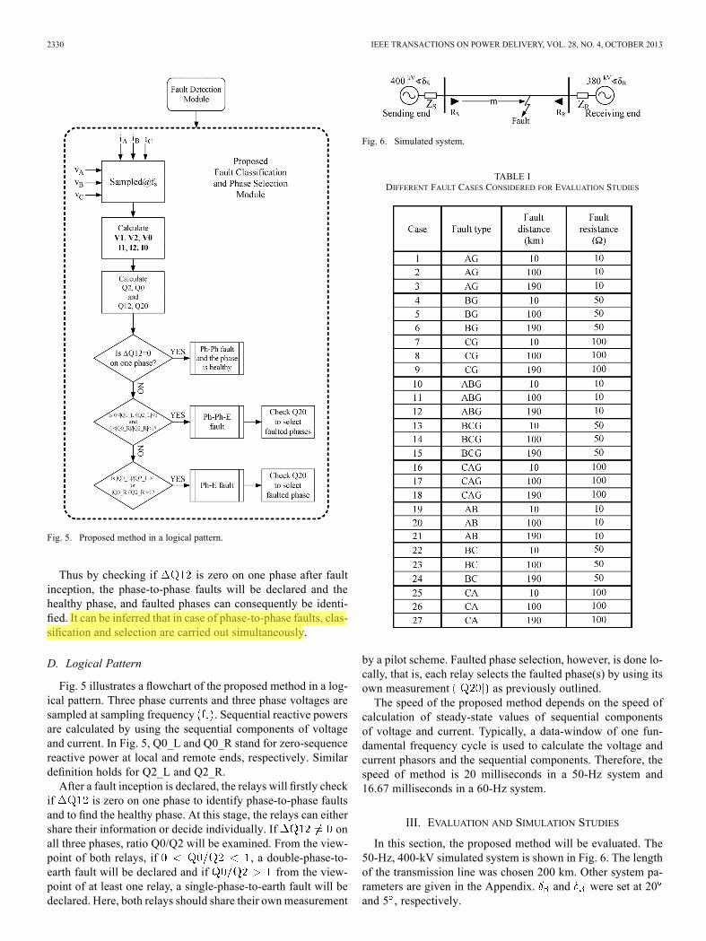
Fig. 5. Proposed method in a logical pattern.
Thus by checking if is zero on one phase after faultinception, the phase-to-phase faults will be declared and thehealthy phase, and faulted phases can consequently be identi-fied. It can be inferred that in case of phase-to-phase faults, clas-sification and selection are carried out simultaneously.
D. Logical Pattern
Fig. 5 illustrates a flowchart of the proposed method in a log-ical pattern. Three phase currents and three phase voltages aresampled at sampling frequency . Sequential reactive powersare calculated by using the sequential components of voltageand current. In Fig. 5, Q0_L and Q0_R stand for zero-sequencereactive power at local and remote ends, respectively. Similardefinition holds for Q2_L and Q2_R.After a fault inception is declared, the relays will firstly check
if is zero on one phase to identify phase-to-phase faultsand to find the healthy phase. At this stage, the relays can eithershare their information or decide individually. If onall three phases, ratio Q0/Q2 will be examined. From the view-point of both relays, if , a double-phase-to-earth fault will be declared and if from the view-point of at least one relay, a single-phase-to-earth fault will bedeclared. Here, both relays should share their ownmeasurement
Fig. 6. Simulated system.
TABLE IDIFFERENT FAULT CASES CONSIDERED FOR EVALUATION STUDIES
by a pilot scheme. Faulted phase selection, however, is done lo-cally, that is, each relay selects the faulted phase(s) by using itsown measurement as previously outlined.The speed of the proposed method depends on the speed of
calculation of steady-state values of sequential componentsof voltage and current. Typically, a data-window of one fun-damental frequency cycle is used to calculate the voltage andcurrent phasors and the sequential components. Therefore, thespeed of method is 20 milliseconds in a 50-Hz system and16.67 milliseconds in a 60-Hz system.
III. EVALUATION AND SIMULATION STUDIES
In this section, the proposed method will be evaluated. The50-Hz, 400-kV simulated system is shown in Fig. 6. The lengthof the transmission line was chosen 200 km. Other system pa-rameters are given in the Appendix. and were set at 20and 5 , respectively.
Usama Ashfaq
Highlight
MAHAMEDI AND ZHU: FAULT CLASSIFICATION AND FAULTED PHASE SELECTION 2331
TABLE IIVALUES MEASURED BY RELAY FOR DIFFERENT GROUNDED FAULTS
TABLE IIIVALUES MEASURED BY RELAY FOR DIFFERENT GROUNDED FAULTS
Different fault cases have been considered as tabulated inTable I. To avoid large numbers, Q20 and are given inper unit (pu) with the base power of 100 MW. As Tables IIand III show, the ratio of Q0/Q2 was more than 1 at eitherone end or both ends in case of single-phase-to-earth faults.This confirmed a single-phase-to-earth fault inception. Forthe AG faults, the maximum occurred on Phase A.For BG and CG faults, maximum occurred on PhasesB and C, respectively. Therefore, the faulted phase was se-lected. For double-phase-to-earth faults, Q0/Q2 was less than1 at both ends, as seen in Tables II and III. This confirmed a
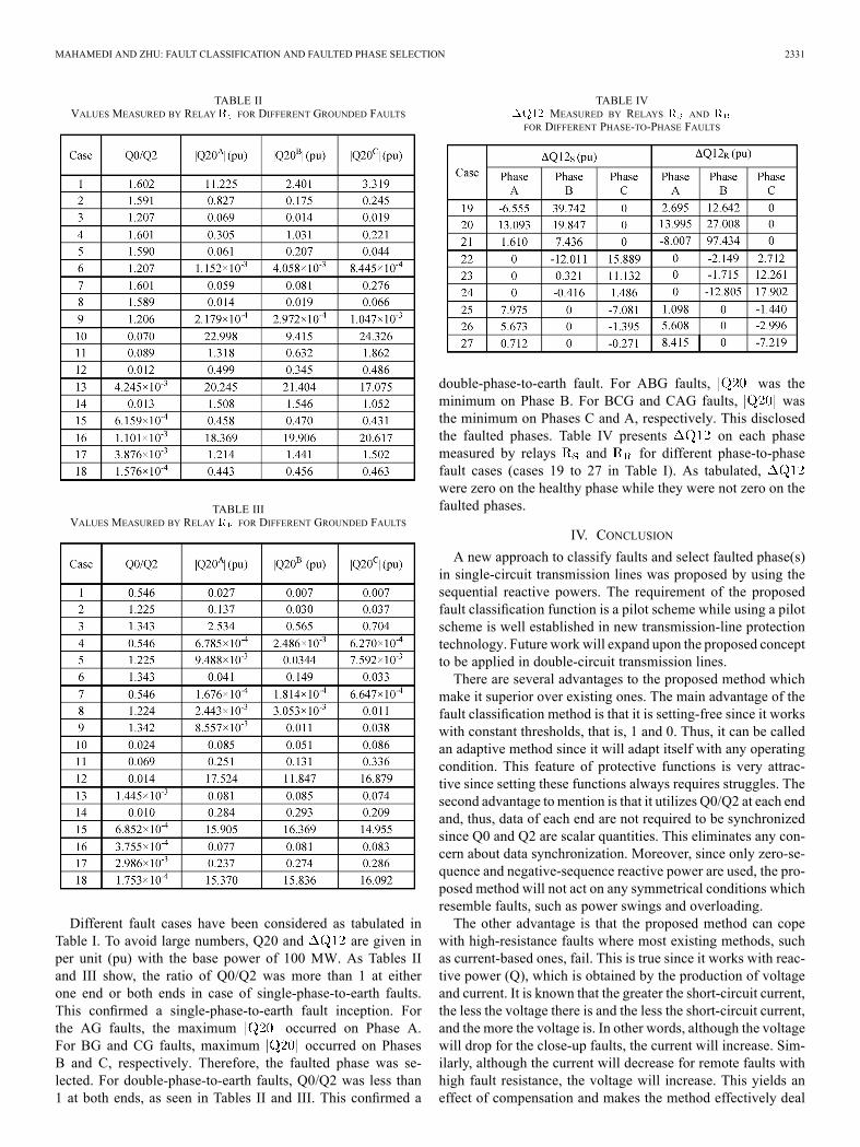
TABLE IVMEASURED BY RELAYS AND
FOR DIFFERENT PHASE-TO-PHASE FAULTS
double-phase-to-earth fault. For ABG faults, was theminimum on Phase B. For BCG and CAG faults, wasthe minimum on Phases C and A, respectively. This disclosedthe faulted phases. Table IV presents on each phasemeasured by relays and for different phase-to-phasefault cases (cases 19 to 27 in Table I). As tabulated,were zero on the healthy phase while they were not zero on thefaulted phases.
IV. CONCLUSION
A new approach to classify faults and select faulted phase(s)in single-circuit transmission lines was proposed by using thesequential reactive powers. The requirement of the proposedfault classification function is a pilot scheme while using a pilotscheme is well established in new transmission-line protectiontechnology. Future work will expand upon the proposed conceptto be applied in double-circuit transmission lines.There are several advantages to the proposed method which
make it superior over existing ones. The main advantage of thefault classification method is that it is setting-free since it workswith constant thresholds, that is, 1 and 0. Thus, it can be calledan adaptive method since it will adapt itself with any operatingcondition. This feature of protective functions is very attrac-tive since setting these functions always requires struggles. Thesecond advantage to mention is that it utilizes Q0/Q2 at each endand, thus, data of each end are not required to be synchronizedsince Q0 and Q2 are scalar quantities. This eliminates any con-cern about data synchronization. Moreover, since only zero-se-quence and negative-sequence reactive power are used, the pro-posed method will not act on any symmetrical conditions whichresemble faults, such as power swings and overloading.The other advantage is that the proposed method can cope
with high-resistance faults where most existing methods, suchas current-based ones, fail. This is true since it works with reac-tive power (Q), which is obtained by the production of voltageand current. It is known that the greater the short-circuit current,the less the voltage there is and the less the short-circuit current,and the more the voltage is. In other words, although the voltagewill drop for the close-up faults, the current will increase. Sim-ilarly, although the current will decrease for remote faults withhigh fault resistance, the voltage will increase. This yields aneffect of compensation and makes the method effectively deal
2332 IEEE TRANSACTIONS ON POWER DELIVERY, VOL. 28, NO. 4, OCTOBER 2013
with extreme scenarios. Another advantage is that the proposedmethod does work with a common sampling frequency used innumerical relays which makes it easy to implement.
APPENDIX
The parameters of the simulated system (illustrated in Fig. 6)are given as follows:Source impedances
Transmission line: distributed model with the followingparameters:
REFERENCES[1] X.-N. Lin, M. Zhao, K. Alymann, and P. Liu, “Novel design of a fast
phase selector using correlation analysis,” IEEE Trans. Power Del.,vol. 20, no. 2, pt. 2, pp. 1283–1290, Apr. 2005.
[2] G. Benmouyal and J. Mahseredjian, “A combined directional andfaulted phase selector element based on incremental quantities,” IEEETrans. Power Del., vol. 16, no. 4, pp. 478–484, Oct. 2001.
[3] T. Adu, “An accurate fault classification technique for power systemmonitoring devices,” IEEE Trans. Power Del., vol. 17, no. 3, pp.684–690, Jul. 2002.
[4] Z. Q. Bo, M. A. Redfern, and G. C. Weller, “Positional protection oftransmission line using fault generated high frequency transient sig-nals,” IEEE Trans. Power Del., vol. 15, no. 3, pp. 888–894, Jul. 2000.
[5] W. L. A. Neves, N. S. D. Brito, B. A. Souza, and A. V. Fontes,“Sampling rate of digital fault recorders influence on fault diagnosis,”in Proc. Transm. Distrib. Conf. Exp., Latin America, Nov. 2004, pp.406–411.
[6] K. M. Silva, K. M. C. Dantas, B. A. Souza, N. S. D. Brito, F. B. Costa,and J. A. C. B. Silva, “Haar wavelet-based method for fast fault classi-fication in transmission lines,” in Proc. IEEE/Power Eng. Soc. Transm.Distrib. Conf. Exp., Latin America, Aug. 2006, pp. 1–5.
[7] X. Dong, W. Kong, and T. Cui, “Fault classification and faulted-phaseselection based on the initial current traveling wave,” IEEE Trans.Power Del., vol. 24, no. 2, pp. 552–559, Apr. 2009.
[8] I. Zamora, A. J. Mazón, V. Valverde, E. Torres, and A. Dysko, “Powerquality and digital protection relays,” presented at the Int. Conf. Renew.Energies Power Qual., Barcelona, Spain, 2004.
[9] A. Jamehbozorg and S. M. Shahrtash, “A decision-tree-based methodfor fault classification in double-circuit transmission lines,” IEEETrans. Power Del., vol. 25, no. 4, pp. 2184–2189, Oct. 2010.
[10] A. Jamehbozorg and S. M. Shahrtash, “A decision-tree-based methodfor fault classification in single-circuit transmission lines,” IEEE Trans.Power Del., vol. 25, no. 4, pp. 2190–2196, Oct. 2010.
[11] H. Saadat, Power System Analysis, 2nd ed. New York: McGraw-Hill,2002.
[12] J. Izykowski, R. Molag, E. Rosolowski, and M. M. Saha, “Accuratelocation of faults on power transmission lines with use of two-end un-synchronized measurements,” IEEE Trans. Power Del., vol. 21, no. 2,pp. 627–633, Apr. 2006.
[13] J. Izykowski, E. Rosolowski, and M. M. Saha, “Postfault analysis ofoperation of distance protective relays of power transmission lines,”IEEE Trans. Power Del., vol. 22, no. 1, pp. 74–81, Jan. 2007.
Behnam Mahamedi was born in Tehran, Iran, in1982. He received the B.Sc. degree in electricalengineering from Iran University of Science andTechnology (IUST), Tehran, in 2005 and the M.Sc.degree in electrical engineering from Shahid Be-heshti University (SBU), Tehran, in 2010.From 2012 to 2013, he was a Researcher with the
University of Technology Sydney (UTS), Sydney,Australia, focusing on power system fault detectionsystems. Since 2008, he has been a ProtectionEngineer with the Iran Grid Management Company
(IGMC), Tehran. His research interests are power system protection, powersystem transient studies, and wavelet-transform applications in power systems.
Jian Guo Zhu (SM’03) received the B.E. degree inelectrical engineering from Jiangsu Institute of Tech-nology, Zhenjiang, China, in 1982, the M.E. degreein electrical engineering from Shanghai University ofTechnology, Shanghai, China, in 1987, and the Ph.D.degree in electrical engineering from the Universityof Technology Sydney (UTS), Sydney, Australia, in1995.Currently, he is a Professor of Electrical En-
gineering and Head of the School of Electrical,Mechanical, and Mechatronic Systems, UTS. His
research interests include electromagnetic and magnetic properties of mate-rials, electrical machines and drives, power electronics, and renewable energysystems.
Related Documents