FASTCAM-APX RS Hardware Manual Rev.1.05 PHOTRON LIMITED MAR.2006

Welcome message from author
This document is posted to help you gain knowledge. Please leave a comment to let me know what you think about it! Share it to your friends and learn new things together.
Transcript
FASTCAM-APX RS
Hardware Manual
Rev.1.05
PHOTRON LIMITED MAR.2006


FASTCAM-APX RS Hardware Manual
-1-
Table of contents Chapter 1 Introduction ............................................................................7
1.1. Preface ...........................................................................................8 1.2. Warranty.........................................................................................9 1.3. How to Use This Manual ............................................................. 11 1.4. Precautions.................................................................................. 13
Chapter 2 Setting Up ............................................................................. 15 2.1. To Start ......................................................................................... 16
2.1.1. Unpacking ............................................................................. 16 2.1.2. Optional Accessories ........................................................... 16
2.2. Names of Components ............................................................... 17 2.2.1. Camera .................................................................................. 17 2.2.2. Names of Camera Components........................................... 18 2.2.3. Changeable Lens Mount ...................................................... 19 2.2.4. Installing Heat Sink(optional) .............................................. 20 2.2.5. Remote Control Keypad....................................................... 21 2.2.6. GENERAL IN Cable............................................................... 22 2.2.7. GENERAL OUT Cable........................................................... 23 2.2.8. MCDL / RS422 Cable (Optional)........................................... 24 2.2.9. DC IN Cable (DC Power IN) .................................................. 26
2.3. System Connection..................................................................... 27 2.3.1. Connecting Remote Control Keypad .................................. 27 2.3.3. Connecting Video Monitor ................................................... 27 2.3.4. Power Connection ................................................................ 28
2.4. Basics of Remote Control Keypad Operation........................... 29 2.4.1. Details of Controls on Keypad............................................. 29 2.4.2. Basic Operation .................................................................... 30 2.4.3. Menu Selection ..................................................................... 31
FASTCAM-APX RS Hardware Manual
-2-
2.4.4. Screen Displays.................................................................... 32 2.4.5. Cancelling Menu Selection .................................................. 33 2.4.6. Storing Menu Settings.......................................................... 33 2.4.7. Menu / Manual Reference..................................................... 34
2.5. System Clock Setup (Date, Time and Revision) ....................... 35 2.5.1. Setting Date and Time .......................................................... 35 2.5.2. Displaying Date or Time....................................................... 36 2.5.3. Displaying System Revision................................................ 37
2.6. Back to Factory Settings ............................................................ 38 Chapter 3 Recording ............................................................................. 39
3.1. Initialization (Calibration) ........................................................... 40 3.1.1. Start Calibration.................................................................... 40 3.1.2. Saving Calibrated Settings .................................................. 41 3.1.3. Loading Calibrated Settings ................................................ 41
3.2. Selecting Frame Rate.................................................................. 42 3.3. Selecting Resolution................................................................... 43 3.4. Selecting Shutter Speed ............................................................. 44
3.4.1. Setting Shutter Speed ..........................................................44 3.4.2. Switching Shutter Modes..................................................... 45 3.4.3. AUTO EXPOSURE Operation............................................... 46
3.5. Selecting Trigger Mode............................................................... 51 3.5.1. START Mode.......................................................................... 52 3.5.2. CENTER Mode ...................................................................... 53 3.5.3. END Mode.............................................................................. 54 3.5.4. MANUAL Mode...................................................................... 55 3.5.5. RANDOM Mode ..................................................................... 57 3.5.6. RANDOM RESET Mode ........................................................ 59 3.5.7. RANDOM CENTER Mode ..................................................... 60 3.5.8. RANDOM MANUAL Mode..................................................... 63 3.5.9. DUAL FRAMING RATE Mode ............................................... 66
FASTCAM-APX RS Hardware Manual
-3-
3.6. VARIABLE Setting Mode............................................................. 69 3.6.1. Setting from Frame Rate ...................................................... 69 3.6.2. Setting from Resolution ....................................................... 72 3.6.2.1. Image window in the screen center ................................. 72 3.6.2.2. Image window in any position.......................................... 74 3.6.3. How to Use Saved Setup Data ............................................. 76 3.6.4. Erasing Setup Data............................................................... 77 3.6.5. Reverting to Default Settings .............................................. 78
3.7. Adjusting White Balance (Color Model only) ............................ 79 3.7.1. Fixed (Preset) White Balance .............................................. 79 3.7.2. Manual (One Touch) White Balance .................................... 80
3.8. Partitioning Memory.................................................................... 81 3.8.1. Prepare for Memory Partitioning (Set Number of Sections)
................................................................................................................. 81 3.8.2. Recording into Divided Sections......................................... 83 3.8.3. Playback of Recorded Sections .......................................... 83 3.8.4. PARTITION MODE................................................................. 84
3.9. LUT (Look-Up Table) Operation ................................................. 85 3.9.1. Operating Preset LUT........................................................... 86 3.9.2. Customizing LUT Patterns................................................... 87 3.9.3. Edge Enhancement .............................................................. 88
3.10. Extended Dynamic Range Mode.............................................. 89 3.11. External Trigger Input ............................................................... 90
3.11.1. Input of External Trigger Signals....................................... 90 3.11.2. Output of Trigger Signals to External Equipment............ 92
3.12. Input of External Sync Signals................................................. 93 3.12.1. Input of External Sync Signals .......................................... 93 3.12.2. Output of External Sync Signals ....................................... 95 3.12.3. Sync Operation of Multiple APX RS Systems .................. 96 3.12.4 Sync Operation with External Equipment ......................... 99
FASTCAM-APX RS Hardware Manual
-4-
3.12.5. Sync Operation of APX RS and Other Models of Cameras............................................................................................................... 102
3.13. Setting GENERAL IN / OUT Signals....................................... 104 3.13.1. Setting GENERAL IN Signals........................................... 104 3.13.2. Setting GENERAL OUT Signals....................................... 106
3.14. Event Marker Function............................................................ 108 3.15. MCDL – Multi-Channel Data Link ........................................... 109 3.16. IRIG Time Code........................................................................ 111 3.17. Direct Trigger Mode................................................................. 113
Chapter 4 Playback.............................................................................. 115 4.1. Playing Recorded Images......................................................... 116 4.2. Searching Images of Interest (Fast Forward/Rewind Play) ... 117 4.3. Slow Playback (Jog).................................................................. 118 4.4. Zooming (Zoom/Fit/Scroll)........................................................ 119
4.4.1. Fitting Image Frame to Video Screen................................ 120 4.4.2. Zooming Playback Image Frame....................................... 121 4.4.3. Scrolling Playback Image Frame....................................... 122
4.5. Block Playback..........................................................................123 4.6. Text Display – Hide / Unhide .................................................... 125 4.7. Displaying Crosshair Cursor.................................................... 126 4.8. Displaying R G B Planes........................................................... 128 4.9. Switching between.................................................................... 129 4.10. Automatic Playback ................................................................ 130 4.11. Playback Event Markers ......................................................... 131
Chapter 5 Connecting APX RS to PC................................................. 133 5.1. Connecting APX RS to a PC..................................................... 134
5.1.1. APX RS. with IEEE1394 Interface ...................................... 134 5.1.2. Connection by Optical Interface........................................ 134 5.1.3. Using Giga Bit Ethernet Interface...................................... 140
5.2. Connecting Multiple APX RS Cameras to a PC ...................... 146
FASTCAM-APX RS Hardware Manual
-5-
5.3. Connecting Mixed Models of Cameras to a PC ...................... 148 Chapter 6 Specifications..................................................................... 150
6.1. Specifications............................................................................ 151 6.1.1. Product Specifications....................................................... 151 6.1.2. Miscellaneous Information ................................................ 152 6.1.3. Standard Equipment and Optional Items.......................... 153 6.1.4. Frame Rates and Resolutions ........................................... 154 6.1.5. Number of Recorded Images vs. Resolution ................... 158 6.1.6. RS422 Serial Control Commands...................................... 159 6.1.7. STATUS OUT ....................................................................... 164 6.1.8. Shutter Speed Table (COARSE Steps) .............................. 165
6.2. Mechanical Data ........................................................................ 168 6.2.1. Camera (in millimeters) ...................................................... 168 6.2.2. Keypad (in millimeters) ...................................................... 169 6.2.3. AC Power Adapter (in millimeters) .................................... 169
6.3. Care of Lenses .......................................................................... 170

FASTCAM-APX RS Hardware Manual
-6-
Memo
FASTCAM-APX RS Hardware Manual
-7-
Chapter 1 Introduction
1.1. Preface
1.2. Warranty
1.3. How to Use This Manual
1.4. Precautions
FASTCAM-APX RS Hardware Manual
-8-
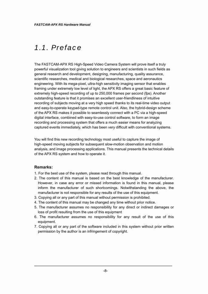
1.1. Preface
The FASTCAM-APX RS High-Speed Video Camera System will prove itself a truly powerful visualization tool giving solution to engineers and scientists in such fields as general research and development, designing, manufacturing, quality assurance, scientific researches, medical and biological researches, space and aeronautics engineering. With its mega-pixel, ultra-high sensitivity imaging sensor that enables framing under extremely low level of light, the APX RS offers a great basic feature of extremely high-speed recording of up to 250,000 frames per second (fps). Another outstanding feature is that it promises an excellent user-friendliness of intuitive recording of subjects moving at a very high speed thanks to its real-time video output and easy-to-operate keypad-type remote control unit. Also, the hybrid-design scheme of the APX RS makes it possible to seamlessly connect with a PC via a high-speed digital interface, combined with easy-to-use control software, to form an image recording and processing system that offers a much easier means for analyzing captured events immediately, which has been very difficult with conventional systems.
You will find this new recording technology most useful to capture the image of high-speed moving subjects for subsequent slow-motion observation and motion analysis, and image processing applications. This manual presents the technical details of the APX RS system and how to operate it.
Remarks: 1. For the best use of the system, please read through this manual. 2. The content of this manual is based on the best knowledge of the manufacturer.
However, in case any error or missed information is found in this manual, please inform the manufacturer of such shortcomings. Notwithstanding the above, the manufacturer is not responsible for any results of the use of this equipment.
3. Copying all or any part of this manual without permission is prohibited. 4. The content of this manual may be changed any time without prior notice. 5. The manufacturer assumes no responsibility for any direct or indirect damages or
loss of profit resulting from the use of this equipment 6. The manufacturer assumes no responsibility for any result of the use of this
equipment. 7. Copying all or any part of the software included in this system without prior written
permission by the author is an infringement of copyright.
FASTCAM-APX RS Hardware Manual
-9-
1.2. Warranty
New Equipment Warranty PHOTRON FASTCAM-APX RS
PHOTRON LIMITED warrants this PHOTRON FASTCAM-APX RS (“APX RS”) and accessories manufactured by PHOTRON LIMITED to function properly for one year from the date of shipment, provided the warranty registration card was filled out and returned to PHOTRON USA, INC. or PHOTRON EUROPE LIMITED within thirty days of shipment. PHOTRON LIMITED, in conjunction with PHOTRON USA, INC. or PHOTRON EUROPE LIMITED, agrees to perform the following equipment warranty services:
1.Repair service: If shipped to PHOTRON at any of the addresses shown below, repairs will be made at no charge.
2.Parts replacement: Replacement parts installed under warranty will be provided at no charge.
THIS WARRANTY DOES NOT APPLY UNDER THE FOLLOWING CONDITIONS: Failure to operate the APX RS in accordance with Photon’s written instructions, including environmental specifications listed in the User’s Manual. If there is evidence of the APX RS being subjected to accidental damage, misuse or abuse. If the APX RS has been repaired or tampered with by persons other than PHOTRON personnel, customer personnel trained by PHOTRON or without permission of PHOTRON. Shipping damage is not covered by this warranty. The purchaser has the responsibility to place a claim of damage in shipment with the carrier.
FASTCAM-APX RS Hardware Manual
-10-
PHOTRON LIMITED makes no other warranties, express or implied, including the implied warranties of merchantability and fitness for a particular purpose. If this APX RS does not function properly during the warranty period, PHOTRON LIMITED will repair it without charge according to the terms stated above. Repair without charge is PHOTRON LIMITED’s only obligation under this warranty. PHOTRON LIMITED, PHOTRON USA, INC. or PHOTRON EUROPE LIMITED will not be responsible for any consequential or incidental damages resulting from the sale, use or improper functioning of this equipment even if loss or damage is caused by the negligence or other fault of PHOTRON LIMITED, PHOTRON USA, INC. or PHOTRON EUROPE LIMITED. Return the equipment that needs warranty service to: In Americas & Antipodes PHOTRON USA, INC. 9520 Padgett Street Suite 110 San Diego, CA 92126-4446 USA Phone: 858-684-3555 Fax: 858-684-3558 E-mail:[email protected] www.photron.com
In Europe: PHOTRON EUROPE LTD. Willowbank House 84 Station Road Marlow, Bucks SL7 1NX U. K. Phone:+44(0) 1628 89 4353 Fax: +44(0) 1628 89 4354 E-mail:[email protected] www.photron.com
In other areas: PHOTRON LIMITED FUjimi 1-1-8, Chiyoda-ku Tokyo 102-0071 Japan Phone:+81 3 3238 2170 Fax: +81 3 3238 2134 E-mail:[email protected] www.photron.co.jp
FASTCAM-APX RS Hardware Manual
-11-
1.3. How to Use This Manual DEFINITION OF TERMS You will notice that some of the information in this manual is presented as a NOTE, CAUTION or WARNING. It is important that you understand the significance of these three terms. For safe operation of the system, please follow the safety instructions below: “Note” includes information that should be emphasized regarding the operation of the APX RS. “Caution” includes important information regarding operation. If it is neglected and the equipment is used in the wrong manner, damage may be caused to the content of recording, the equipment and related peripheral devices. “Warning” presents very important information regarding safety of the operators. If it is neglected and the equipment is used in the wrong manner, a serious hazardous sequence involving human injury or death may result. It must not be disregarded. Chapters This manual is divided into six chapters each discussing subject matters related to its chapter title. Chapter 1. Introduction Contains Warranty, precautions, introduction and how to use this manual. Chapter 2. Set Up Introduces you to the components of the APX RS and explains the use of each connector, keypad operation and parameter settings to make ready for recording. Chapter 3. Recording Explains the operation of the APX RS for recording. Chapter 4. Playback Discusses playback of recorded images and filing image data.
FASTCAM-APX RS Hardware Manual
-12-
Chapter 5. Connection to a PC Shows how to connect and operate the APX RS to a PC (Operation of the APX RS from PC is discussed in the PFV Software Manual). Chapter 6. Specifications Provides detailed specifications of the APX RS system.
FASTCAM-APX RS Hardware Manual
-13-
1.4. Precautions Ambient Temperature Photron FASTCAM-APX RS has been designed to work properly in an ambient temperature range of 0 to 40 degrees Celsius (32 to 104 degrees Fahrenheit), no condensation.To use the system in ambient temperature of over 35 degrees Celeius a special heet sink(optional) must be used. Storage Temperature The APX RS must be stored in a place with an ambient temperature range of -20 to +70 degrees Celsius (-4 to +158 degrees Fahrenheit), no condensation. Transportation Save the original carton the unit came in for future transportation. Do not transport the unit under ambient temperature of below -20 degrees Celsius (-4 degrees Fahrenheit) or above 70 degrees Celsius (+158 degrees Fahrenheit). WARNING This product is grounded through the power cord. This protective ground connection is essential for safe operation of the equipment. Avoid electrical shock by plugging the power cord into a properly wired power outlet. A loss of the protective grounding, for any reason, could result in electrical shock. Use the proper power cord and insure that it is in good condition. FEDERAL COMMUNICATIONS COMMISSION STATEMENTS WARNING: This equipment generates, uses and can radiate radio frequency energy and if not installed and used in accordance with the instruction manual, may cause interference to radio communications. It has been tested and found to comply with the limits for a Class computing device pursuant to Subpart A of Part 15 of the FCC Rules and VDE 0871 Class B which are designed to provide reasonable protection against such interference when operated in a commercial environment. Operation of this equipment in a residential area is likely to cause interference, in which case the user, at the user’s own expense, will be required to take whatever measures may be required to correct the interference. This device complies with Part 15 of the FCC Rules and VDE 0871. Operation is subject to the following two conditions: (1) this equipment may cause harmful interference, and (2) this equipment must accept any interference received including interference that may cause undesired operation.

FASTCAM-APX RS Hardware Manual
-14-
Memo
FASTCAM-APX RS Hardware Manual
-15-
Chapter 2 Setting Up
2.1. To Start 2.2. Names of Components 2.3. System Connection 2.4. Basics of Remote Control Keypad Operation 2.5. System Setup 2.6. Back to Factory Settings
FASTCAM-APX RS Hardware Manual
-16-
2.1. To Start 2.1.1. Unpacking The APX RS system consists of the following items. Make sure if all the components are found in the package.
1. Camera 1 ea. 2. Remote Control Keypad 1 ea. 3. AC Power Adapter with AC Cable 1 ea. 4. C-Mount Lens Adapter 1 ea. 5. Allen Wrench for Changing Lens Mounts (1.5, 2 and 4 mm) 1 ea. 6. Lens Mount Cap (Camera inclusion) 1 ea. 7. GENERAL IN Cable 1 ea. 8. GENERAL OUT Cable 1.ea. 9. Remote Keypad Bouncer 1 ea. 10. CD-ROM For Driver/Application Setup 1 ea. 11. FASTCAM-ultima APX RS Hardware Manual 1 ea. 12. FASTCAM Control Software Operation Manual 1 ea. 13. Warranty Registration Card 1 ea. 14. Digital Interface Cable(IEEE1394 Cable) 1 ea.* 15. IEEE1394 6-pin to 4-pin Conversion Connector 1 ea.* 16. Optical Fiber Cable 1 ea.* 17. Cable clamps 4 ea.* 18. Optical PCI Interface Board 1 ea.* 19. Digital Interface Cable(LAN Cable) 1 ea.* 20. IP Address sticker 1 ea.* 21. Setup Manual 1 ea.*
Note :Items 14 and 15 is IEEE1394 Interface. (5 meters long) Note :Items 16 17 and 18 is optical Interface.
Optical cable is a single mode fiber cable 9/125 micrometers SMF (5 meters long). Note :Items 19,20 and 21 is Giga Bit Ethernet Interface. Giga Bit Ethernet cable is CAT6 Shield
Straight (10 meters long).
2.1.2. Optional Accessories Following optional items are available for the APX RS:
1. Additional Memory Unit (to be installed at factory only) 2. High-G Mount Kit 3. IEEE1394 Optical Link (IEEE1394 Optical fiber extension unit) 4. MCDL/RS422 Compound Cable 5. Output Trigger Box 6. 4-ch MCDL Analog Waveform Sync Recording Unit 7. Small-sized LCD Monitor (with cables and mounting adapter) 8. Aluminum Carrying Case 9. Spare Power Connector (for Custom Cable) 10. Heat Sink 11. Dustproof shells and cap for Giga Bit Ethernet Interface
FASTCAM-APX RS Hardware Manual
-17-
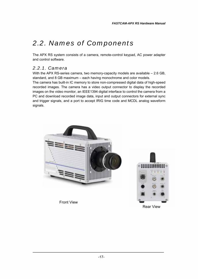
2.2. Names of Components The APX RS system consists of a camera, remote-control keypad, AC power adapter and control software. 2.2.1. Camera With the APX RS-series camera, two memory-capacity models are available – 2.6 GB, standard, and 8 GB maximum – each having monochrome and color models. The camera has built-in IC memory to store non-compressed digital data of high-speed recorded images. The camera has a video output connector to display the recorded images on the video monitor, an IEEE1394 digital interface to control the camera from a PC and download recorded image data, input and output connectors for external sync and trigger signals, and a port to accept IRIG time code and MCDL analog waveform signals.
Front View Rear View
FASTCAM-APX RS Hardware Manual
-18-
IEEE 1394
DC IN
MJ -19
12V 0.8ADC OUT
RECIRIGTRIGGERLINKPOWER
MCDLRS422
GENERAL OUT
GENERAL IN
VIDEO OUT 2
VIDEO OUT 1
REMOTECONTROLLER
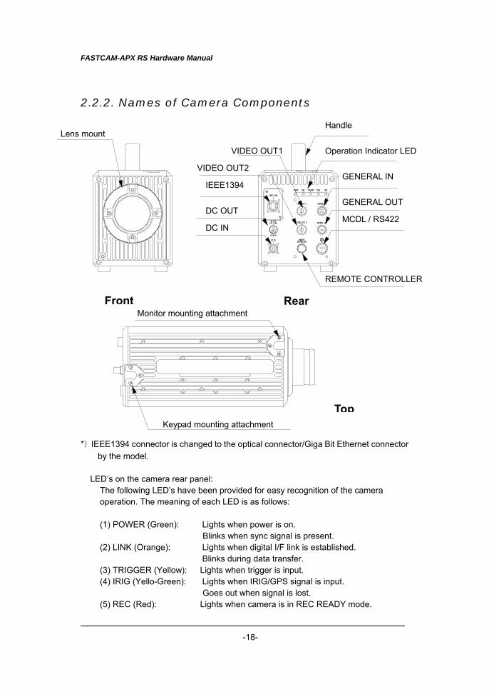
2.2.2. Names of Camera Components *)IEEE1394 connector is changed to the optical connector/Giga Bit Ethernet connector
by the model. LED’s on the camera rear panel:
The following LED’s have been provided for easy recognition of the camera operation. The meaning of each LED is as follows: (1) POWER (Green): Lights when power is on.
Blinks when sync signal is present. (2) LINK (Orange): Lights when digital I/F link is established.
Blinks during data transfer. (3) TRIGGER (Yellow): Lights when trigger is input. (4) IRIG (Yello-Green): Lights when IRIG/GPS signal is input.
Goes out when signal is lost. (5) REC (Red): Lights when camera is in REC READY mode.
Front Rear
Top
Lens mount Handle
Operation Indicator LED
GENERAL IN
GENERAL OUT
MCDL / RS422
REMOTE CONTROLLER
Monitor mounting attachment
Keypad mounting attachment
VIDEO OUT1
VIDEO OUT2
IEEE1394
DC OUT
DC IN
FASTCAM-APX RS Hardware Manual
-19-
Blinks when camera is in REC mode.
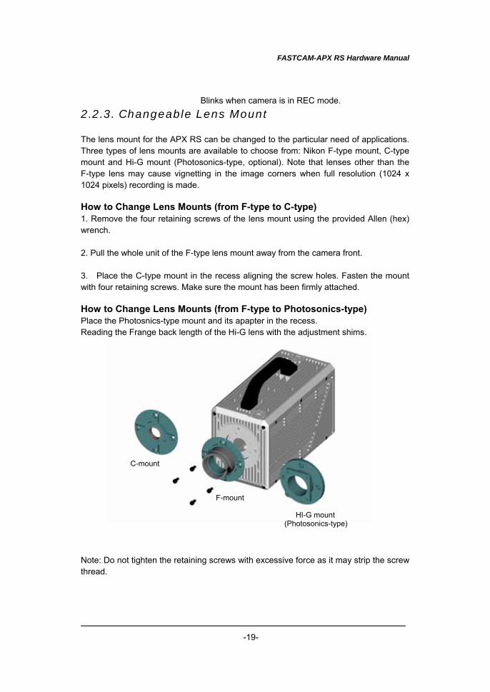
2.2.3. Changeable Lens Mount The lens mount for the APX RS can be changed to the particular need of applications. Three types of lens mounts are available to choose from: Nikon F-type mount, C-type mount and Hi-G mount (Photosonics-type, optional). Note that lenses other than the F-type lens may cause vignetting in the image corners when full resolution (1024 x 1024 pixels) recording is made. How to Change Lens Mounts (from F-type to C-type) 1. Remove the four retaining screws of the lens mount using the provided Allen (hex) wrench. 2. Pull the whole unit of the F-type lens mount away from the camera front.
3. Place the C-type mount in the recess aligning the screw holes. Fasten the mount with four retaining screws. Make sure the mount has been firmly attached.
How to Change Lens Mounts (from F-type to Photosonics-type) Place the Photosnics-type mount and its apapter in the recess. Reading the Frange back length of the Hi-G lens with the adjustment shims. Note: Do not tighten the retaining screws with excessive force as it may strip the screw thread.
C-mount
F-mount
HI-G mount (Photosonics-type)
FASTCAM-APX RS Hardware Manual
-20-
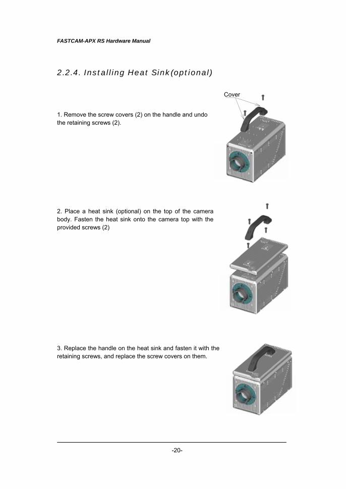
2.2.4. Installing Heat Sink(optional) 1. Remove the screw covers (2) on the handle and undo the retaining screws (2). 2. Place a heat sink (optional) on the top of the camera body. Fasten the heat sink onto the camera top with the provided screws (2)
3. Replace the handle on the heat sink and fasten it with the retaining screws, and replace the screw covers on them.
Cover
FASTCAM-APX RS Hardware Manual
-21-
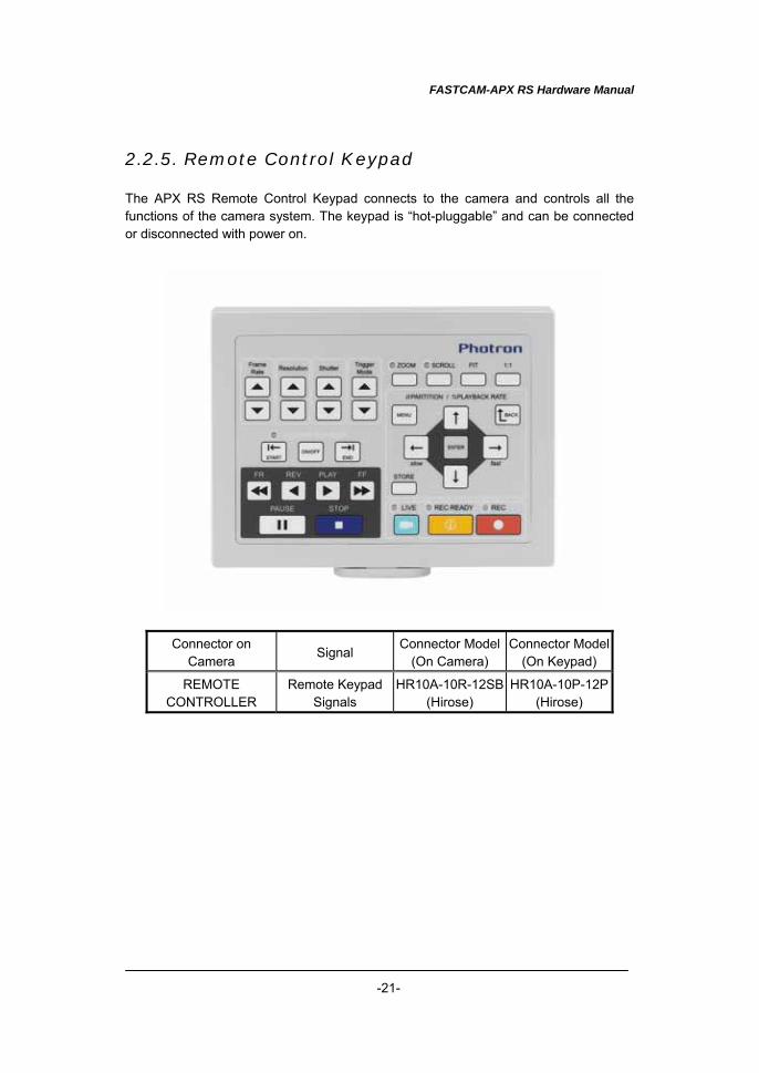
2.2.5. Remote Control Keypad The APX RS Remote Control Keypad connects to the camera and controls all the functions of the camera system. The keypad is “hot-pluggable” and can be connected or disconnected with power on.
Connector on Camera
Signal Connector Model
(On Camera) Connector Model
(On Keypad)
REMOTE CONTROLLER
Remote Keypad Signals
HR10A-10R-12SB(Hirose)
HR10A-10P-12P (Hirose)
FASTCAM-APX RS Hardware Manual
-22-
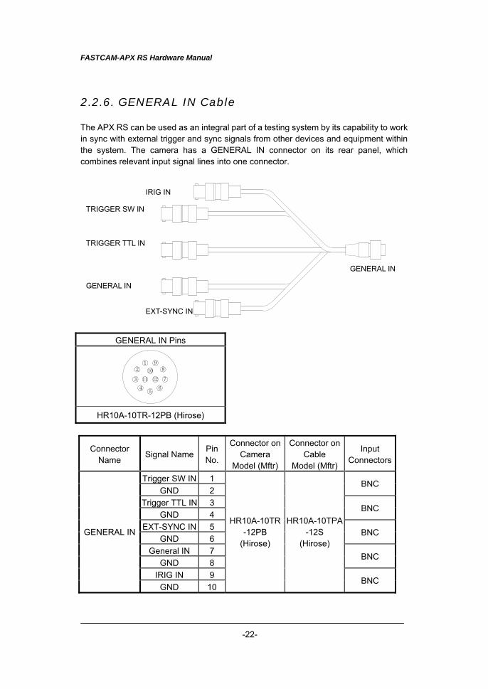
2.2.6. GENERAL IN Cable The APX RS can be used as an integral part of a testing system by its capability to work in sync with external trigger and sync signals from other devices and equipment within the system. The camera has a GENERAL IN connector on its rear panel, which combines relevant input signal lines into one connector.
GENERAL IN Pins
12
3
456
7
89
10
11 12
HR10A-10TR-12PB (Hirose)
Connector Name
Signal NamePin No.
Connector on Camera
Model (Mftr)
Connector on Cable
Model (Mftr)
Input Connectors
Trigger SW IN 1 GND 2
BNC
Trigger TTL IN 3 GND 4
BNC
EXT-SYNC IN 5 GND 6
BNC
General IN 7 GND 8
BNC
IRIG IN 9
GENERAL IN
GND 10
HR10A-10TR-12PB
(Hirose)
HR10A-10TPA-12S
(Hirose)
BNC
IRIG IN
TRIGGER SW IN
TRIGGER TTL IN
GENERAL IN
EXT-SYNC IN
GENERAL IN
FASTCAM-APX RS Hardware Manual
-23-
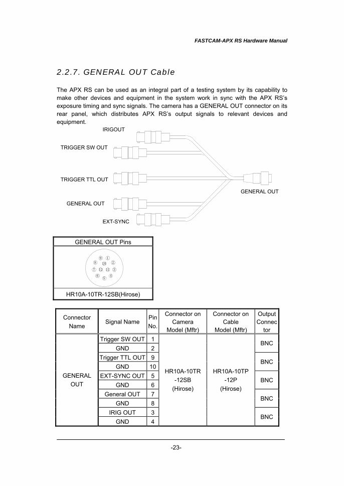
2.2.7. GENERAL OUT Cable The APX RS can be used as an integral part of a testing system by its capability to make other devices and equipment in the system work in sync with the APX RS’s exposure timing and sync signals. The camera has a GENERAL OUT connector on its rear panel, which distributes APX RS’s output signals to relevant devices and equipment.
GENERAL OUT Pins
12
3
45
6
7
89
10
1112
HR10A-10TR-12SB(Hirose)
Connector Name
Signal Name Pin No.
Connector on Camera
Model (Mftr)
Connector on Cable
Model (Mftr)
Output Connec
tor Trigger SW OUT 1
GND 2 BNC
Trigger TTL OUT 9 GND 10
BNC
EXT-SYNC OUT 5 GND 6
BNC
General OUT 7 GND 8
BNC
IRIG OUT 3
GENERAL OUT
GND 4
HR10A-10TR-12SB
(Hirose)
HR10A-10TP-12P
(Hirose)
BNC
IRIGOUT
TRIGGER SW OUT
TRIGGER TTL OUT
EXT-SYNC
GENERAL OUT
GENERAL OUT
FASTCAM-APX RS Hardware Manual
-24-
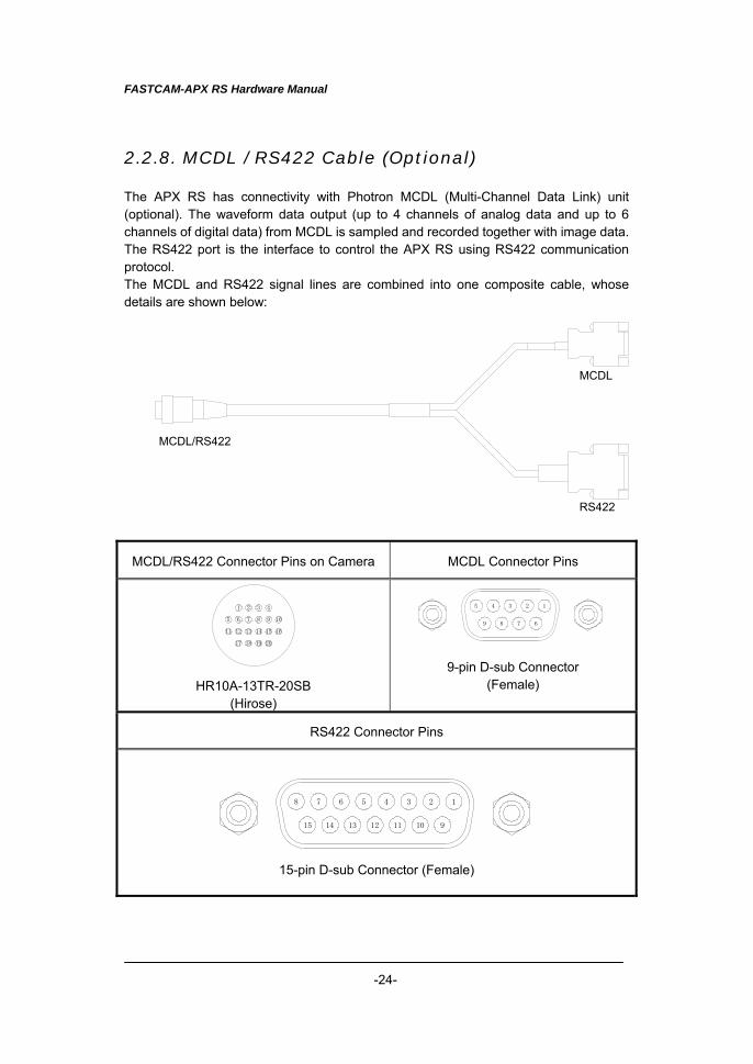
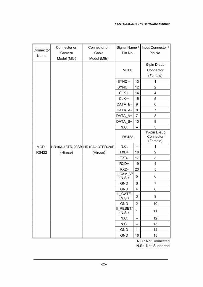
2.2.8. MCDL / RS422 Cable (Optional) The APX RS has connectivity with Photron MCDL (Multi-Channel Data Link) unit (optional). The waveform data output (up to 4 channels of analog data and up to 6 channels of digital data) from MCDL is sampled and recorded together with image data. The RS422 port is the interface to control the APX RS using RS422 communication protocol. The MCDL and RS422 signal lines are combined into one composite cable, whose details are shown below:
MCDL/RS422 Connector Pins on Camera MCDL Connector Pins
1 2 3 4
5 6 7 8 9 10
11 12 13 14 15 16
17 18 19 20
HR10A-13TR-20SB
(Hirose)
12345
6789
9-pin D-sub Connector
(Female)
RS422 Connector Pins
12345678
9101112131415
15-pin D-sub Connector (Female)
RS422
MCDL
MCDL/RS422
FASTCAM-APX RS Hardware Manual
-25-
Connector Name
Connector on Camera
Model (Mftr)
Connector on Cable
Model (Mftr)
Signal Name / Pin No.
Input Connector / Pin No.
MCDL 9-pin D-sub Connector (Female)
SYNC- 13 1 SYNC+ 12 2 CLK+ 14 4 CLK- 15 5
DATA_B- 9 6 DATA_A- 8 7 DATA_A+ 7 8 DATA_B+ 10 9
N.C. -- 3
RS422 15-pin D-sub Connector (Female)
N.C. -- 1 TXD+ 18 2 TXD- 17 3 RXD+ 19 4 RXD- 20 5
II_CAM_V/(N.S.) 5 6
GND 6 7 GND 4 8
II_GATE(N.S.) 3 9
GND 2 10 II_RESET/(N.S.) 1 11
N.C. -- 12 N.C. -- 13 GND 11 14
MCDL RS422
HR10A-13TR-20SB(Hirose)
HR10A-13TPD-20P(Hirose)
GND 16 15 N.C.: Not Connected N.S.: Not Supported
FASTCAM-APX RS Hardware Manual
-26-
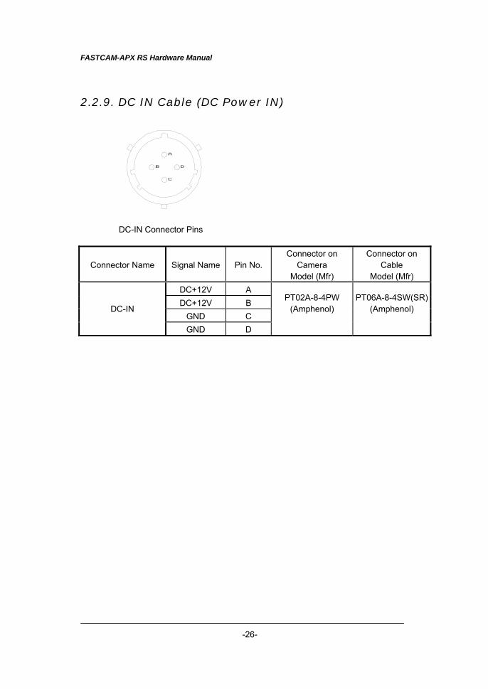
2.2.9. DC IN Cable (DC Power IN)
DC-IN Connector Pins
Connector Name Signal Name Pin No.Connector on
Camera Model (Mfr)
Connector on Cable
Model (Mfr) DC+12V A DC+12V B
GND C DC-IN
GND D
PT02A-8-4PW (Amphenol)
PT06A-8-4SW(SR) (Amphenol)
A
C
DB
FASTCAM-APX RS Hardware Manual
-27-
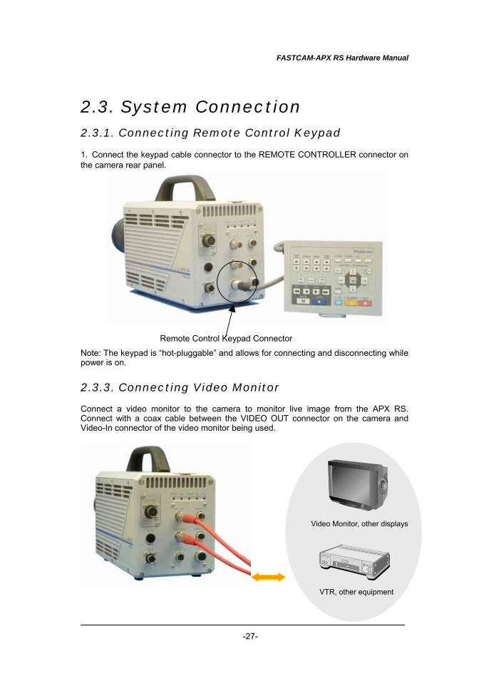
2.3. System Connection 2.3.1. Connecting Remote Control Keypad 1. Connect the keypad cable connector to the REMOTE CONTROLLER connector on the camera rear panel. Note: The keypad is “hot-pluggable” and allows for connecting and disconnecting while power is on.
2.3.3. Connecting Video Monitor Connect a video monitor to the camera to monitor live image from the APX RS. Connect with a coax cable between the VIDEO OUT connector on the camera and Video-In connector of the video monitor being used.
Remote Control Keypad Connector
Video Monitor, other displays
VTR, other equipment
FASTCAM-APX RS Hardware Manual
-28-
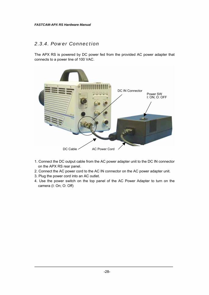
2.3.4. Power Connection The APX RS is powered by DC power fed from the provided AC power adapter that connects to a power line of 100 VAC. 1. Connect the DC output cable from the AC power adapter unit to the DC IN connector
on the APX RS rear panel. 2. Connect the AC power cord to the AC IN connector on the AC power adapter unit. 3. Plug the power cord into an AC outlet. 4. Use the power switch on the top panel of the AC Power Adapter to turn on the
camera (I: On; O: Off)
Power SW I: ON; O: OFF
AC Power Cord DC Cable
DC IN Connector
FASTCAM-APX RS Hardware Manual
-29-
2.4. Basics of Remote Control Keypad Operation
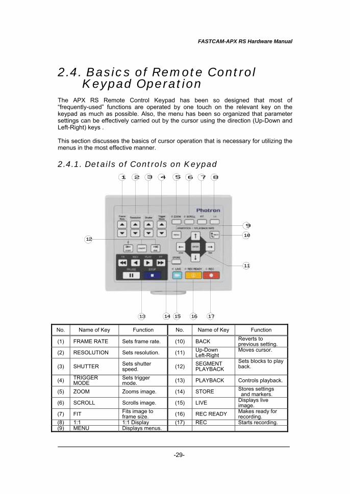
The APX RS Remote Control Keypad has been so designed that most of “frequently-used” functions are operated by one touch on the relevant key on the keypad as much as possible. Also, the menu has been so organized that parameter settings can be effectively carried out by the cursor using the direction (Up-Down and Left-Right) keys . This section discusses the basics of cursor operation that is necessary for utilizing the menus in the most effective manner. 2.4.1. Details of Controls on Keypad No. Name of Key Function No. Name of Key Function
(1) FRAME RATE Sets frame rate. (10) BACK Reverts to previous setting.
(2) RESOLUTION Sets resolution. (11) Up-Down Left-Right
Moves cursor.
(3) SHUTTER Sets shutter speed. (12) SEGMENT
PLAYBACK Sets blocks to play back.
(4) TRIGGER MODE
Sets trigger mode. (13) PLAYBACK Controls playback.
(5) ZOOM Zooms image. (14) STORE Stores settings and markers.
(6) SCROLL Scrolls image. (15) LIVE Displays live image.
(7) FIT Fits image to frame size. (16) REC READY Makes ready for
recording. (8) 1:1 1:1 Display (17) REC Starts recording. (9) MENU Displays menus.
1 2 3 4 5 6 7 8
9
10
11
12
13 14 15 16 17
FASTCAM-APX RS Hardware Manual
-30-
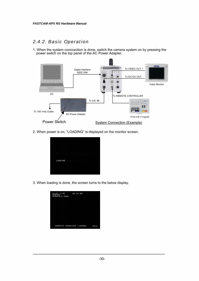
2.4.2. Basic Operation 1. When the system conncection is done, switch the camera system on by pressing the
power switch on the top panel of the AC Power Adapter.
System Connection (Example) 2. When power is on, “LOADING” is displayed on the monitor screen. 3. When loading is done, the screen turns to the below display.
To 100 VAC Outlet
To DC IN
To REMOTE CONTROLLERPC
Digital InterfaceIEEE1394
To DC12V OUT
To VIDEO OUT 1
AC Power Adapter
Video Monitor
Remote Keypad
Power Switch
FASTCAM-APX RS Hardware Manual
-31-
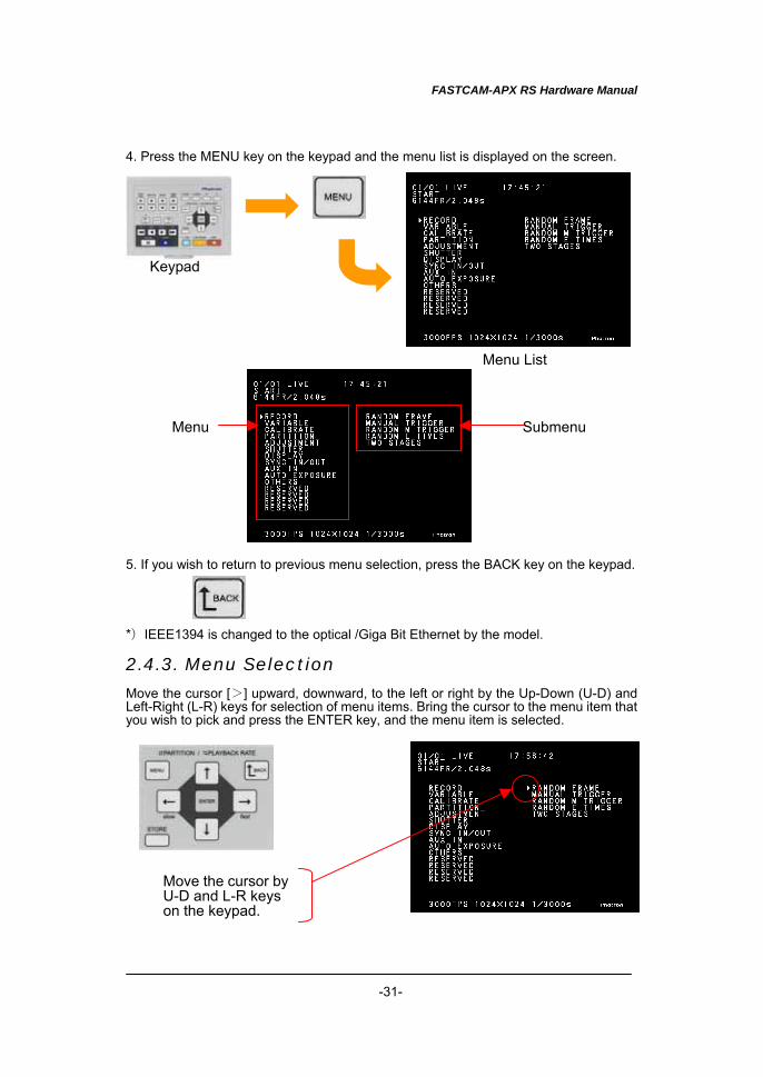
4. Press the MENU key on the keypad and the menu list is displayed on the screen. 5. If you wish to return to previous menu selection, press the BACK key on the keypad. *)IEEE1394 is changed to the optical /Giga Bit Ethernet by the model. 2.4.3. Menu Selection Move the cursor [>] upward, downward, to the left or right by the Up-Down (U-D) and Left-Right (L-R) keys for selection of menu items. Bring the cursor to the menu item that you wish to pick and press the ENTER key, and the menu item is selected.
Keypad
Menu List
Menu Submenu
Move the cursor byU-D and L-R keys on the keypad.
FASTCAM-APX RS Hardware Manual
-32-
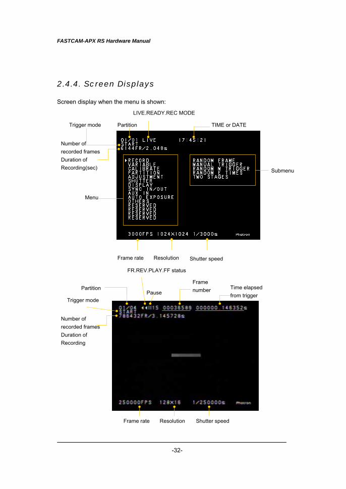
2.4.4. Screen Displays Screen display when the menu is shown:
Shutter speed Resolution Frame rate
Menu
Submenu
Trigger mode
LIVE.READY.REC MODE
TIME or DATE Partition
Shutter speed ResolutionFrame rate
Partition
Trigger modePause
Frame number Time elapsed
from trigger
Number of recorded framesDuration of Recording(sec)
FR.REV.PLAY.FF status
Number of recorded framesDuration of Recording
FASTCAM-APX RS Hardware Manual
-33-
2.4.5. Cancelling Menu Selection To cancel selecton of a menu item while the menu is shown on the screen, simply press the MENU key.
2.4.6. Storing Menu Settings After making necessary selections in the main menu and submenu, press the STORE key on the keypad to store the menu settings. The stored settings are retained even after the system is powered off.
FASTCAM-APX RS Hardware Manual
-34-
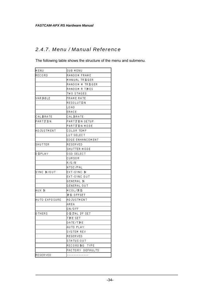
2.4.7. Menu / Manual Reference The following table shows the structure of the menu and submenu. MENU SUB MENU
RECORD RANDOM FRAME
MANUAL TRIGGER
RANDOM M TRIGGER
RANDOM R TIMES
TWO STAGES
VARIABLE FRAME RATE
RESOLUTION
LOAD
ERACE
CALIBRATE CALIBRATE
PARTITION PARTITION SETUP
PARTITION MODE
ADJUSTMENT COLOR TEMP
LUT SELECT
EDGE ENHANCEMENT
SHUTTER RESERVED
SHUTTER MODE
DISPLAY OSD SELECT
CURSOR
R/G/B
NTSC/PAL
SYNC IN/OUT EXT-SYNC IN
EXT-SYNC OUT
GENERAL IN
GENERAL OUT
AUX IN MCDL/IRIG
IRIG OFFSET
AUTO EXPOSURE ADJUSTMENT
AREA
ON/OFF
OTHERS DIGITAL I/F SET
TIME SET
DATE/TIME
AUTO PLAY
SYSTEM REV
RESERVED
STATUS OUT
RECORDING TYPE
FACTORY DEFAULTS
RESERVED -------------
FASTCAM-APX RS Hardware Manual
-35-
2.5. System Clock Setup (Date, Time and Revision) This section discusses how to set up the internal clock of the APX RS system. Date and time are correctly set up and are stored as part of recorded image data. Once the clock is set up, it is supported by an internal battery and the date and time are retained correctly even when the main power is turned off.
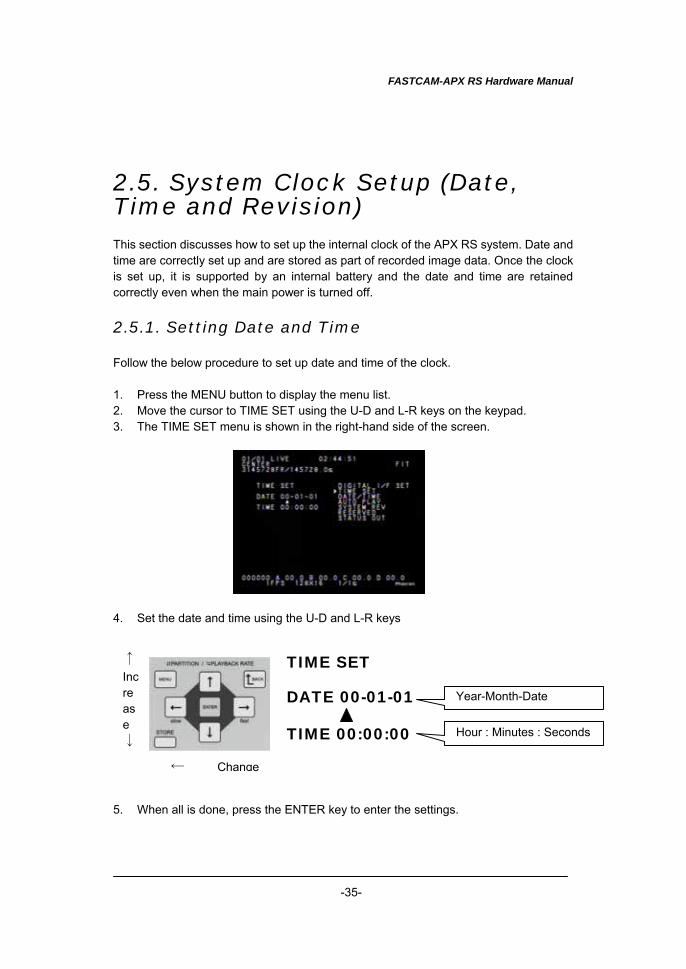
2.5.1. Setting Date and Time Follow the below procedure to set up date and time of the clock. 1. Press the MENU button to display the menu list. 2. Move the cursor to TIME SET using the U-D and L-R keys on the keypad. 3. The TIME SET menu is shown in the right-hand side of the screen. 4. Set the date and time using the U-D and L-R keys 5. When all is done, press the ENTER key to enter the settings.
TIME SET
DATE 00-01-01
TIME 00:00:00
↑ Increase ↓
← Change
Year-Month-Date
Hour : Minutes : Seconds
FASTCAM-APX RS Hardware Manual
-36-
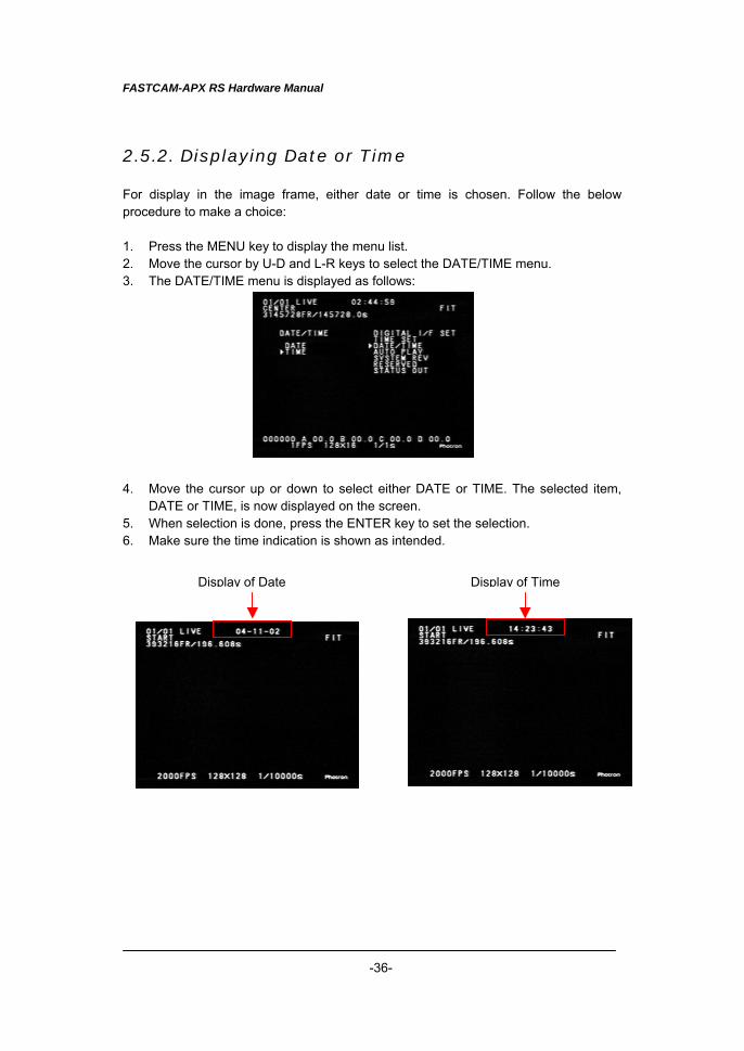
2.5.2. Displaying Date or Time For display in the image frame, either date or time is chosen. Follow the below procedure to make a choice: 1. Press the MENU key to display the menu list. 2. Move the cursor by U-D and L-R keys to select the DATE/TIME menu. 3. The DATE/TIME menu is displayed as follows: 4. Move the cursor up or down to select either DATE or TIME. The selected item,
DATE or TIME, is now displayed on the screen. 5. When selection is done, press the ENTER key to set the selection. 6. Make sure the time indication is shown as intended.
Display of Date Display of Time
FASTCAM-APX RS Hardware Manual
-37-
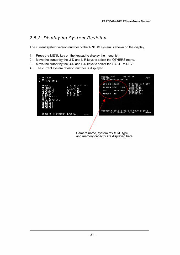
2.5.3. Displaying System Revision The current system version number of the APX RS system is shown on the display. 1. Press the MENU key on the keypad to display the menu list. 2. Move the cursor by the U-D and L-R keys to select the OTHERS menu. 3. Move the cursor by the U-D and L-R keys to select the SYSTEM REV. 4. The current system revision number is displayed.
Camera name, system rev #, I/F type, and memory capacity are displayed here.
FASTCAM-APX RS Hardware Manual
-38-
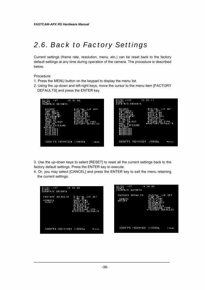
2.6. Back to Factory Settings Current settings (frame rate, resolution, menu, etc.) can be reset back to the factory default settings at any time during operation of the camera. The procedure is described below. Procedure: 1. Press the MENU button on the keypad to display the menu list. 2. Using the up-down and left-right keys, move the cursor to the menu item [FACTORY
DEFAULTS] and press the ENTER key. 3. Use the up-down keys to select [RESET] to reset all the current settings back to the factory default settings. Press the ENTER key to execute. 4. Or, you may select [CANCEL] and press the ENTER key to exit the menu retaining
the current settings.
FASTCAM-APX RS Hardware Manual
-39-
Chapter 3 Recording
3.1. Initialization (Calibration - Shading Correction) 3.2. Selecting Frame Rate 3.3. Selecting Resolution 3.4. Selecting Shutter Speed 3.5. Selecting Trigger Mode 3.6. VARIABLE Setting Mode 3.7. Adjusting White Balance (Color Model) 3.8. Partitioning Memory 3.9. LUT (Look-Up Table) Operation 3.10. Extended Dynamic Range Mode 3.11. External Trigger Input 3.12. External Sync Input 3.13. Setting Input and Output Signals 3.14. Event Marker Function 3.15. MCDL - Multi Channel Data Link 3.16. IRIG Time Code 3.17. Direct Trigger Mode
FASTCAM-APX RS Hardware Manual
-40-
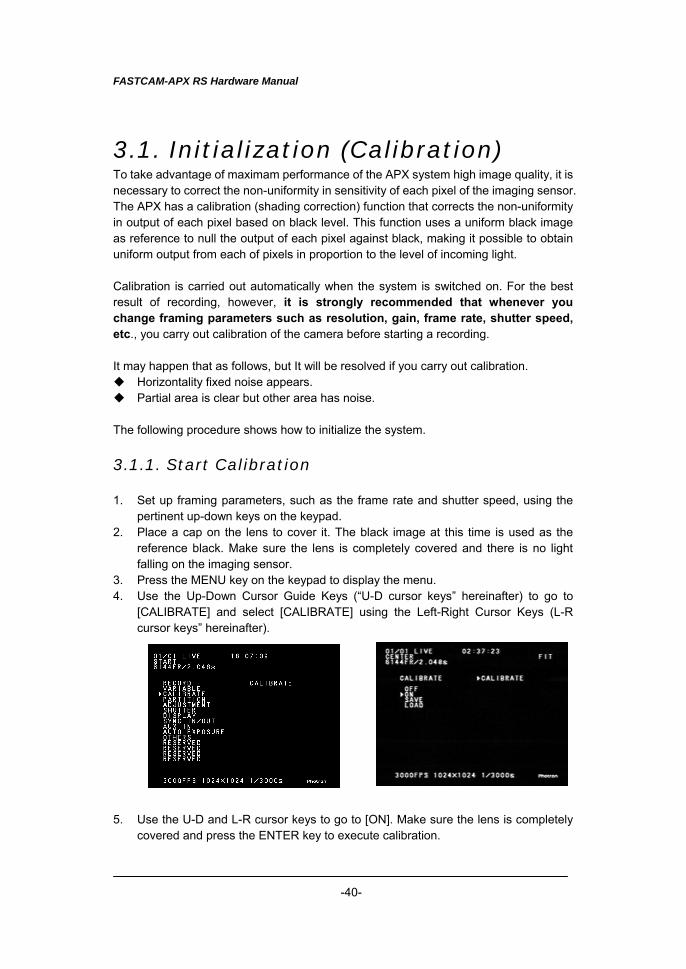
3.1. Initialization (Calibration) To take advantage of maximam performance of the APX system high image quality, it is necessary to correct the non-uniformity in sensitivity of each pixel of the imaging sensor. The APX has a calibration (shading correction) function that corrects the non-uniformity in output of each pixel based on black level. This function uses a uniform black image as reference to null the output of each pixel against black, making it possible to obtain uniform output from each of pixels in proportion to the level of incoming light. Calibration is carried out automatically when the system is switched on. For the best result of recording, however, it is strongly recommended that whenever you change framing parameters such as resolution, gain, frame rate, shutter speed, etc., you carry out calibration of the camera before starting a recording. It may happen that as follows, but It will be resolved if you carry out calibration. ◆ Horizontality fixed noise appears. ◆ Partial area is clear but other area has noise. The following procedure shows how to initialize the system.
3.1.1. Start Calibration 1. Set up framing parameters, such as the frame rate and shutter speed, using the
pertinent up-down keys on the keypad. 2. Place a cap on the lens to cover it. The black image at this time is used as the
reference black. Make sure the lens is completely covered and there is no light falling on the imaging sensor.
3. Press the MENU key on the keypad to display the menu. 4. Use the Up-Down Cursor Guide Keys (“U-D cursor keys” hereinafter) to go to
[CALIBRATE] and select [CALIBRATE] using the Left-Right Cursor Keys (L-R cursor keys” hereinafter).
5. Use the U-D and L-R cursor keys to go to [ON]. Make sure the lens is completely
covered and press the ENTER key to execute calibration.
FASTCAM-APX RS Hardware Manual
-41-
6. Remove the lens cap and make sure the corrected image is displayed on the monitor screen.
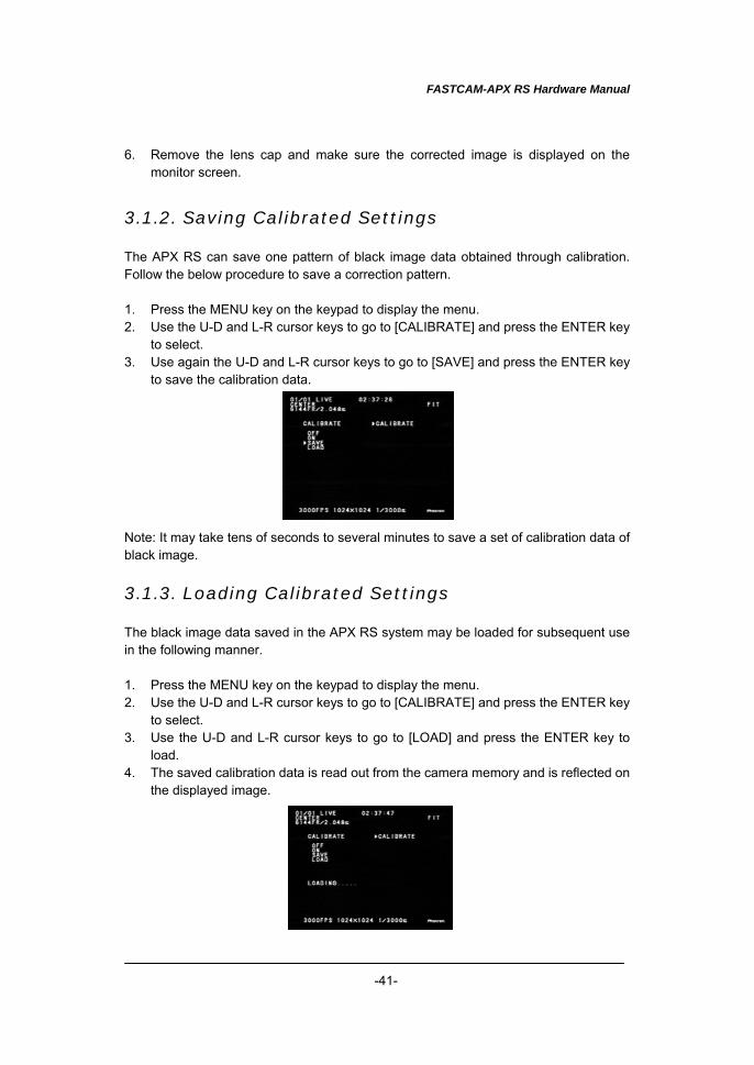
3.1.2. Saving Calibrated Settings The APX RS can save one pattern of black image data obtained through calibration. Follow the below procedure to save a correction pattern. 1. Press the MENU key on the keypad to display the menu. 2. Use the U-D and L-R cursor keys to go to [CALIBRATE] and press the ENTER key
to select. 3. Use again the U-D and L-R cursor keys to go to [SAVE] and press the ENTER key
to save the calibration data. Note: It may take tens of seconds to several minutes to save a set of calibration data of black image.
3.1.3. Loading Calibrated Settings The black image data saved in the APX RS system may be loaded for subsequent use in the following manner. 1. Press the MENU key on the keypad to display the menu. 2. Use the U-D and L-R cursor keys to go to [CALIBRATE] and press the ENTER key
to select. 3. Use the U-D and L-R cursor keys to go to [LOAD] and press the ENTER key to
load. 4. The saved calibration data is read out from the camera memory and is reflected on
the displayed image.
FASTCAM-APX RS Hardware Manual
-42-
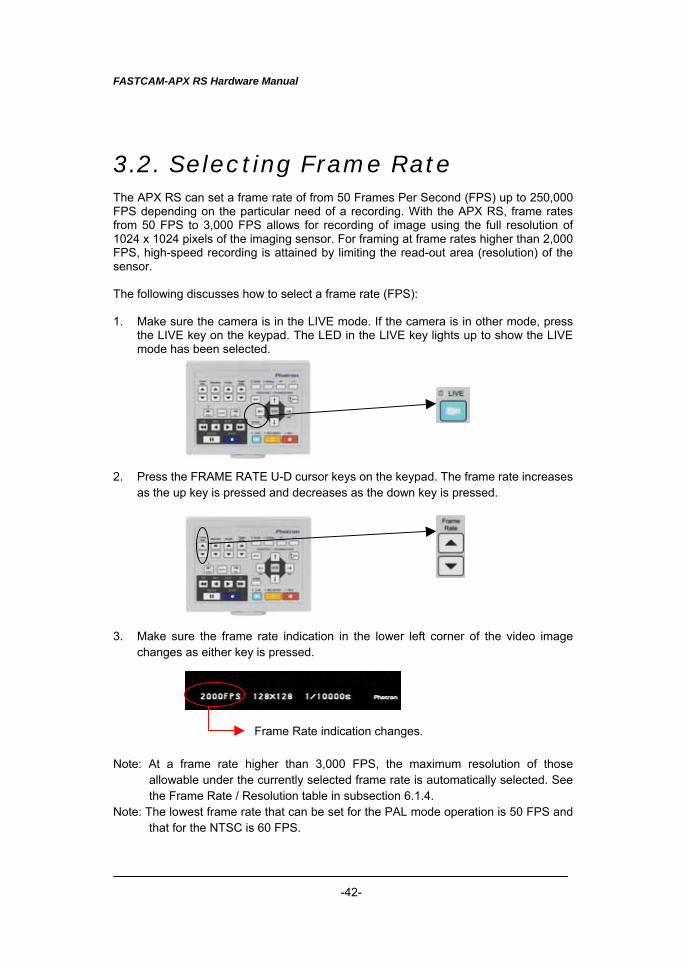
3.2. Selecting Frame Rate The APX RS can set a frame rate of from 50 Frames Per Second (FPS) up to 250,000 FPS depending on the particular need of a recording. With the APX RS, frame rates from 50 FPS to 3,000 FPS allows for recording of image using the full resolution of 1024 x 1024 pixels of the imaging sensor. For framing at frame rates higher than 2,000 FPS, high-speed recording is attained by limiting the read-out area (resolution) of the sensor. The following discusses how to select a frame rate (FPS): 1. Make sure the camera is in the LIVE mode. If the camera is in other mode, press
the LIVE key on the keypad. The LED in the LIVE key lights up to show the LIVE mode has been selected.
2. Press the FRAME RATE U-D cursor keys on the keypad. The frame rate increases
as the up key is pressed and decreases as the down key is pressed. 3. Make sure the frame rate indication in the lower left corner of the video image
changes as either key is pressed. Note: At a frame rate higher than 3,000 FPS, the maximum resolution of those
allowable under the currently selected frame rate is automatically selected. See the Frame Rate / Resolution table in subsection 6.1.4.
Note: The lowest frame rate that can be set for the PAL mode operation is 50 FPS and that for the NTSC is 60 FPS.
Frame Rate indication changes.
FASTCAM-APX RS Hardware Manual
-43-
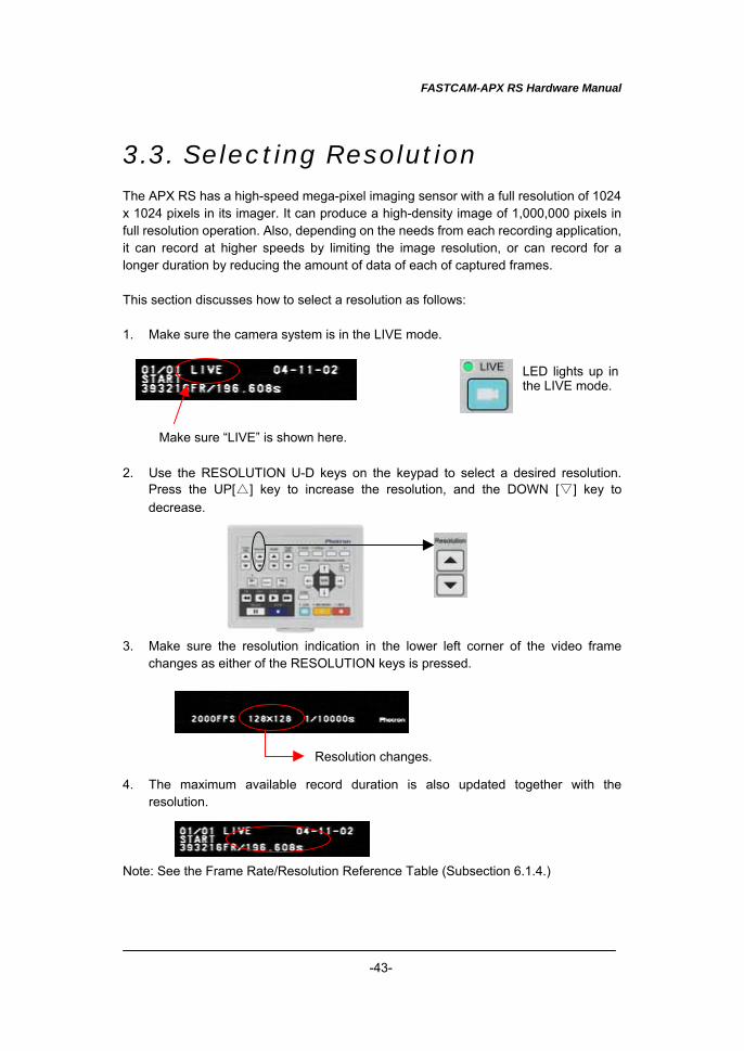
3.3. Selecting Resolution The APX RS has a high-speed mega-pixel imaging sensor with a full resolution of 1024 x 1024 pixels in its imager. It can produce a high-density image of 1,000,000 pixels in full resolution operation. Also, depending on the needs from each recording application, it can record at higher speeds by limiting the image resolution, or can record for a longer duration by reducing the amount of data of each of captured frames. This section discusses how to select a resolution as follows: 1. Make sure the camera system is in the LIVE mode. 2. Use the RESOLUTION U-D keys on the keypad to select a desired resolution.
Press the UP[△] key to increase the resolution, and the DOWN [▽] key to decrease.
3. Make sure the resolution indication in the lower left corner of the video frame
changes as either of the RESOLUTION keys is pressed. 4. The maximum available record duration is also updated together with the
resolution. Note: See the Frame Rate/Resolution Reference Table (Subsection 6.1.4.)
Make sure “LIVE” is shown here.
LED lights up inthe LIVE mode.
Resolution changes.
FASTCAM-APX RS Hardware Manual
-44-
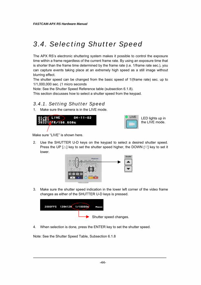
3.4. Selecting Shutter Speed The APX RS’s electronic shuttering system makes it possible to control the exposure time within a frame regardless of the current frame rate. By using an exposure time that is shorter than the frame time determined by the frame rate (i.e. 1/frame rate sec.), you can capture events taking place at an extremely high speed as a still image without blurring effect. The shutter speed can be changed from the basic speed of 1/(frame rate) sec. up to 1/1,000,000 sec. (1 micro seconds Note: See the Shutter Speed Reference table (subsection 6.1.8). This section discusses how to select a shutter speed from the keypad.
3.4.1. Setting Shutter Speed 1. Make sure the camera is in the LIVE mode. 2. Use the SHUTTER U-D keys on the keypad to select a desired shutter speed.
Press the UP [△] key to set the shutter speed higher, the DOWN [▽] key to set it lower.
3. Make sure the shutter speed indication in the lower left corner of the video frame
changes as either of the SHUTTER U-D keys is pressed. 4. When selection is done, press the ENTER key to set the shutter speed. Note: See the Shutter Speed Table, Subsection 6.1.8
Make sure “LIVE” is shown here.
LED lights up in the LIVE mode.
Shutter speed changes.
FASTCAM-APX RS Hardware Manual
-45-
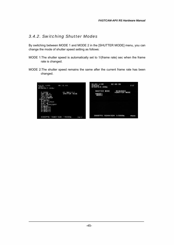
3.4.2. Switching Shutter Modes By switching between MODE 1 and MODE 2 in the [SHUTTER MODE] menu, you can change the mode of shutter speed setting as follows: MODE 1:The shutter speed is automatically set to 1/(frame rate) sec when the frame
rate is changed. MODE 2:The shutter speed remains the same after the current frame rate has been
changed.
FASTCAM-APX RS Hardware Manual
-46-
3.4.3. AUTO EXPOSURE Operation The FASTCAM-APX RS has a newly added function that automatically controls the shuttering of exposure to the image sensor against the incoming light amount so that the level of output image signal is kept to a desired value. This feature is useful for framing applications of subjects where the illumination of the subject enevitably varies even after the camera has been set up and no further camera setup adjustment is possible. To take advantage of this function, the pre-adjustment should be made on the following four items each of which has the following meaning: ・AREA Sets the range of image area. It works in a way that the average of image output level of a selected area is adjusted to a desired level. ・TARGET_VALUE Sets the image output to your desired level. The level is set in 8-bit grayscale (0 to 255). ・RANGE Determines a range to a desired image output level. The width of range is set in 8-bit grayscale (0 to 255). It varies the shutter setting so that the average of the range selected by AREA will be within the range of defined by [TARGET_VALUE±RANGE]. If the width of RANGE is set too narrow, it will be hard to set up the shutter to an appropriate value, which results in flickering of image. ・SHUTTER Sets the longest exposure time. This function prevents image blurring caused by too long an exposure time. This function allows no exposure time to be set longer than the shutter value that is set here.
FASTCAM-APX RS Hardware Manual
-47-
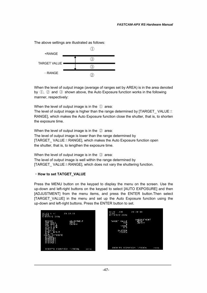
The above settings are illustrated as follows: When the level of output image (average of ranges set by AREA) is in the area denoted by ①, ② and ③ shown above, the Auto Exposure function works in the following manner, respectively: When the level of output image is in the ① area: The level of output image is higher than the range determined by [TARGET_ VALUE±RANGE], which makes the Auto Exposure function close the shutter, that is, to shorten the exposure time. When the level of output image is in the ② area: The level of output image is lower than the range determined by [TARGET_ VALUE±RANGE], which makes the Auto Exposure function open the shutter, that is, to lengthen the exposure time. When the level of output image is in the ③ area: The level of output image is well within the range determined by [TARGET_ VALUE±RANGE], which does not vary the shuttering function. ・How to set TATGET_VALUE Press the MENU button on the keypad to display the menu on the screen. Use the up-down and left-right buttons on the keypad to select [AUTO EXPOSURE] and then [ADJUSTMENT] from the menu items, and press the ENTER button.Then select [TARGET_VALUE] in the menu and set up the Auto Exposure function using the up-down and left-right buttons. Press the ENTER button to set.
TARGET VALUE
+RANGE
-RANGE
③
③
①
②
FASTCAM-APX RS Hardware Manual
-48-
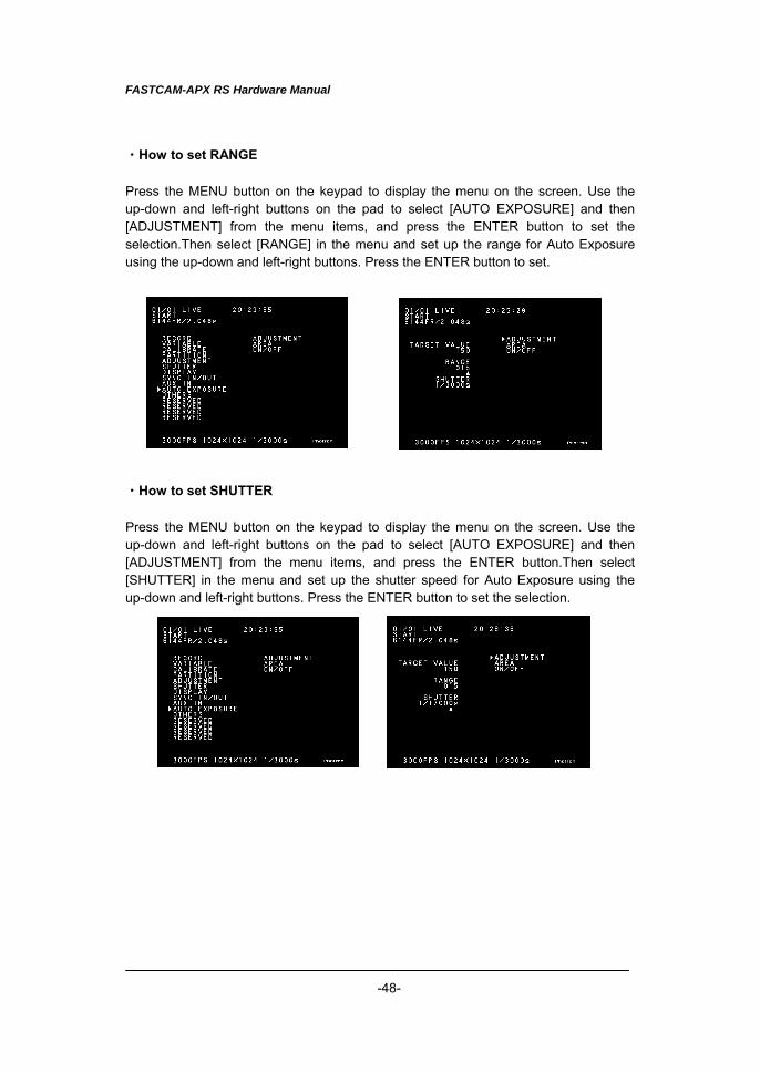
・How to set RANGE Press the MENU button on the keypad to display the menu on the screen. Use the up-down and left-right buttons on the pad to select [AUTO EXPOSURE] and then [ADJUSTMENT] from the menu items, and press the ENTER button to set the selection.Then select [RANGE] in the menu and set up the range for Auto Exposure using the up-down and left-right buttons. Press the ENTER button to set. ・How to set SHUTTER Press the MENU button on the keypad to display the menu on the screen. Use the up-down and left-right buttons on the pad to select [AUTO EXPOSURE] and then [ADJUSTMENT] from the menu items, and press the ENTER button.Then select [SHUTTER] in the menu and set up the shutter speed for Auto Exposure using the up-down and left-right buttons. Press the ENTER button to set the selection.
FASTCAM-APX RS Hardware Manual
-49-
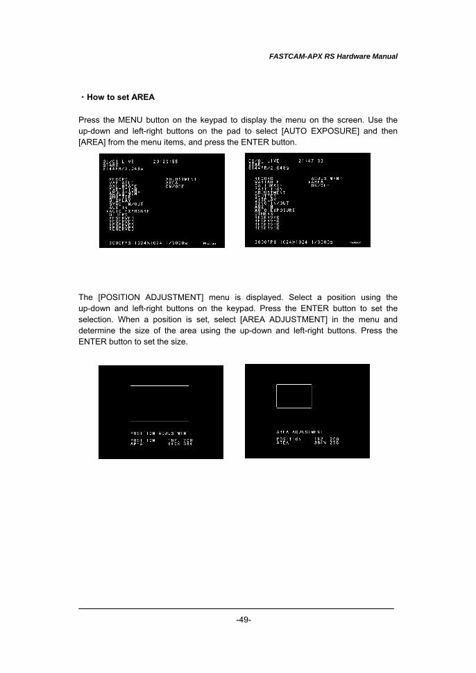
・How to set AREA Press the MENU button on the keypad to display the menu on the screen. Use the up-down and left-right buttons on the pad to select [AUTO EXPOSURE] and then [AREA] from the menu items, and press the ENTER button. The [POSITION ADJUSTMENT] menu is displayed. Select a position using the up-down and left-right buttons on the keypad. Press the ENTER button to set the selection. When a position is set, select [AREA ADJUSTMENT] in the menu and determine the size of the area using the up-down and left-right buttons. Press the ENTER button to set the size.
FASTCAM-APX RS Hardware Manual
-50-
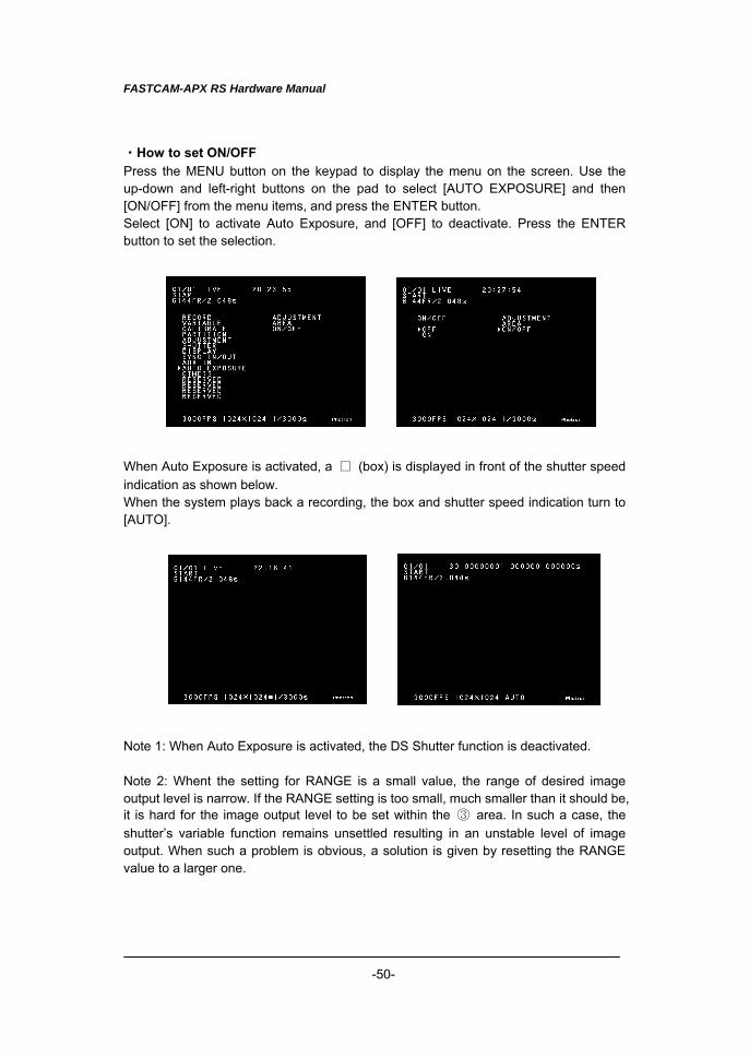
・How to set ON/OFF Press the MENU button on the keypad to display the menu on the screen. Use the up-down and left-right buttons on the pad to select [AUTO EXPOSURE] and then [ON/OFF] from the menu items, and press the ENTER button. Select [ON] to activate Auto Exposure, and [OFF] to deactivate. Press the ENTER button to set the selection. When Auto Exposure is activated, a □ (box) is displayed in front of the shutter speed indication as shown below. When the system plays back a recording, the box and shutter speed indication turn to [AUTO]. Note 1: When Auto Exposure is activated, the DS Shutter function is deactivated. Note 2: Whent the setting for RANGE is a small value, the range of desired image output level is narrow. If the RANGE setting is too small, much smaller than it should be, it is hard for the image output level to be set within the ③ area. In such a case, the shutter’s variable function remains unsettled resulting in an unstable level of image output. When such a problem is obvious, a solution is given by resetting the RANGE value to a larger one.
FASTCAM-APX RS Hardware Manual
-51-
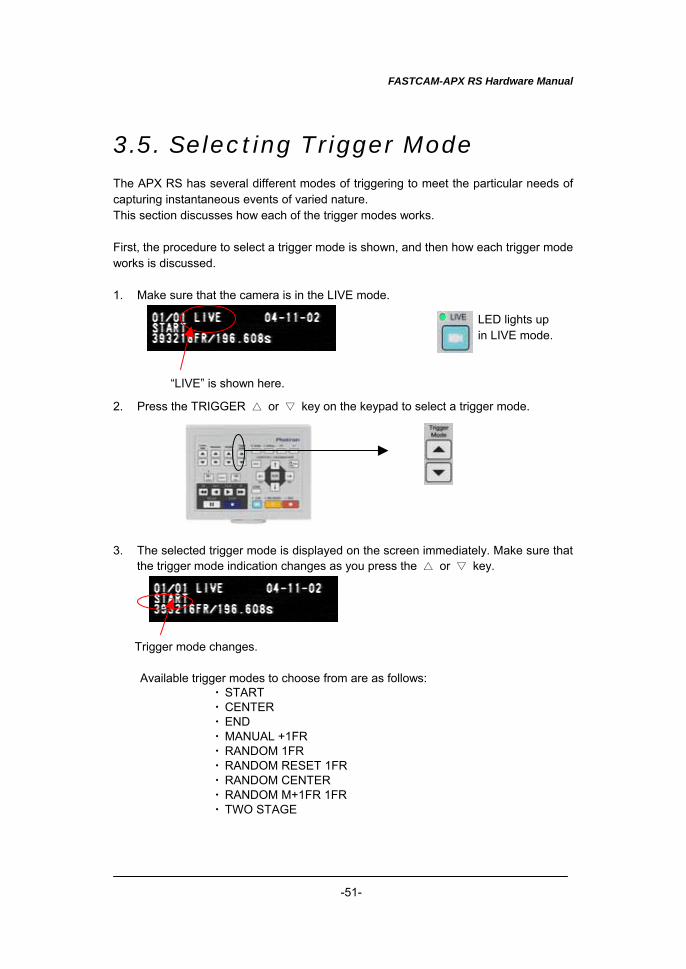
3.5. Selecting Trigger Mode The APX RS has several different modes of triggering to meet the particular needs of capturing instantaneous events of varied nature. This section discusses how each of the trigger modes works. First, the procedure to select a trigger mode is shown, and then how each trigger mode works is discussed. 1. Make sure that the camera is in the LIVE mode. 2. Press the TRIGGER △ or ▽ key on the keypad to select a trigger mode. 3. The selected trigger mode is displayed on the screen immediately. Make sure that
the trigger mode indication changes as you press the △ or ▽ key.
Available trigger modes to choose from are as follows: ・ START ・ CENTER ・ END ・ MANUAL +1FR ・ RANDOM 1FR ・ RANDOM RESET 1FR ・ RANDOM CENTER ・ RANDOM M+1FR 1FR ・ TWO STAGE
“LIVE” is shown here.
LED lights up in LIVE mode.
Trigger mode changes.
FASTCAM-APX RS Hardware Manual
-52-
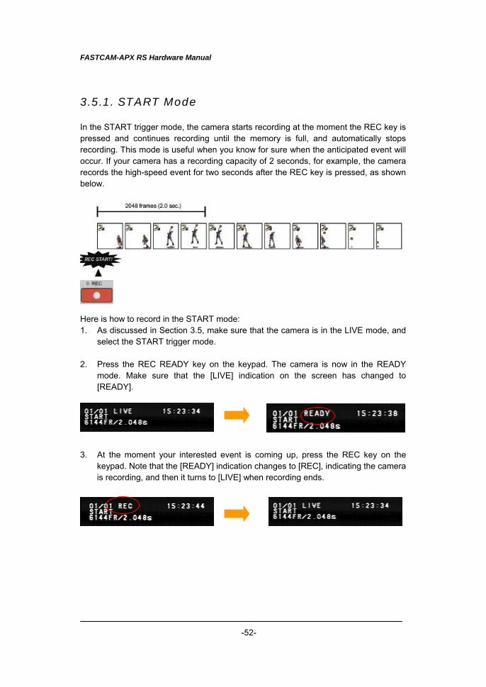
3.5.1. START Mode In the START trigger mode, the camera starts recording at the moment the REC key is pressed and continues recording until the memory is full, and automatically stops recording. This mode is useful when you know for sure when the anticipated event will occur. If your camera has a recording capacity of 2 seconds, for example, the camera records the high-speed event for two seconds after the REC key is pressed, as shown below. Here is how to record in the START mode: 1. As discussed in Section 3.5, make sure that the camera is in the LIVE mode, and
select the START trigger mode. 2. Press the REC READY key on the keypad. The camera is now in the READY
mode. Make sure that the [LIVE] indication on the screen has changed to [READY].
3. At the moment your interested event is coming up, press the REC key on the
keypad. Note that the [READY] indication changes to [REC], indicating the camera is recording, and then it turns to [LIVE] when recording ends.
FASTCAM-APX RS Hardware Manual
-53-
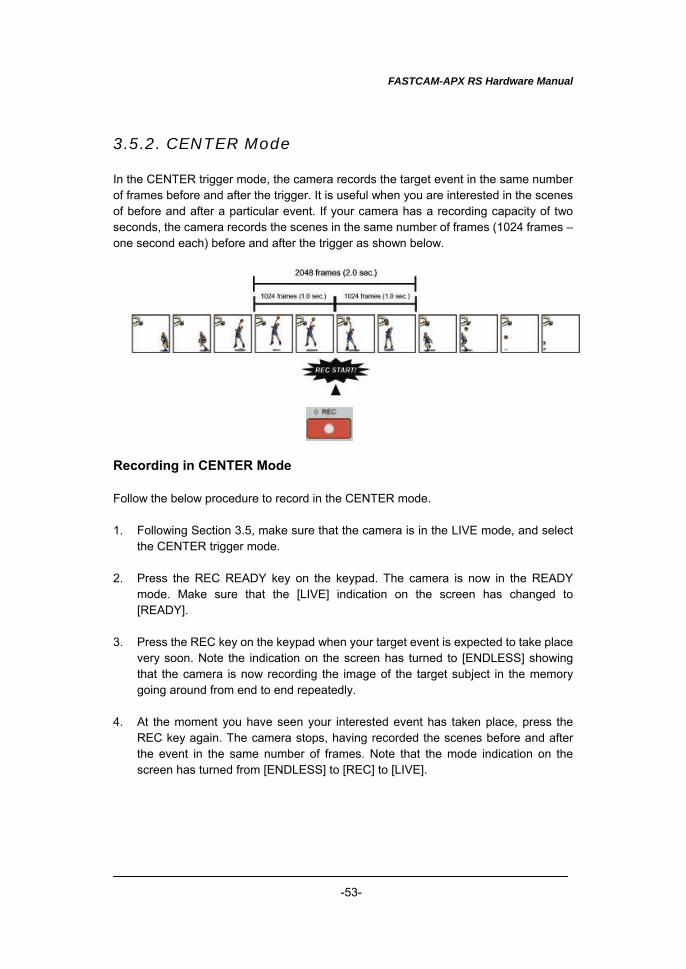
3.5.2. CENTER Mode In the CENTER trigger mode, the camera records the target event in the same number of frames before and after the trigger. It is useful when you are interested in the scenes of before and after a particular event. If your camera has a recording capacity of two seconds, the camera records the scenes in the same number of frames (1024 frames – one second each) before and after the trigger as shown below. Recording in CENTER Mode Follow the below procedure to record in the CENTER mode. 1. Following Section 3.5, make sure that the camera is in the LIVE mode, and select
the CENTER trigger mode. 2. Press the REC READY key on the keypad. The camera is now in the READY
mode. Make sure that the [LIVE] indication on the screen has changed to [READY].
3. Press the REC key on the keypad when your target event is expected to take place
very soon. Note the indication on the screen has turned to [ENDLESS] showing that the camera is now recording the image of the target subject in the memory going around from end to end repeatedly.
4. At the moment you have seen your interested event has taken place, press the
REC key again. The camera stops, having recorded the scenes before and after the event in the same number of frames. Note that the mode indication on the screen has turned from [ENDLESS] to [REC] to [LIVE].
FASTCAM-APX RS Hardware Manual
-54-
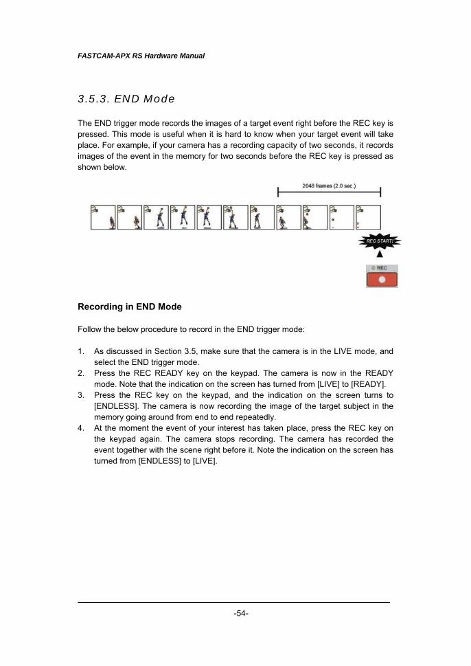
3.5.3. END Mode The END trigger mode records the images of a target event right before the REC key is pressed. This mode is useful when it is hard to know when your target event will take place. For example, if your camera has a recording capacity of two seconds, it records images of the event in the memory for two seconds before the REC key is pressed as shown below. Recording in END Mode Follow the below procedure to record in the END trigger mode: 1. As discussed in Section 3.5, make sure that the camera is in the LIVE mode, and
select the END trigger mode. 2. Press the REC READY key on the keypad. The camera is now in the READY
mode. Note that the indication on the screen has turned from [LIVE] to [READY]. 3. Press the REC key on the keypad, and the indication on the screen turns to
[ENDLESS]. The camera is now recording the image of the target subject in the memory going around from end to end repeatedly.
4. At the moment the event of your interest has taken place, press the REC key on the keypad again. The camera stops recording. The camera has recorded the event together with the scene right before it. Note the indication on the screen has turned from [ENDLESS] to [LIVE].
FASTCAM-APX RS Hardware Manual
-55-
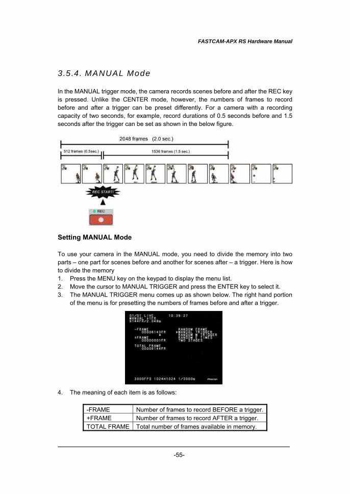
3.5.4. MANUAL Mode In the MANUAL trigger mode, the camera records scenes before and after the REC key is pressed. Unlike the CENTER mode, however, the numbers of frames to record before and after a trigger can be preset differently. For a camera with a recording capacity of two seconds, for example, record durations of 0.5 seconds before and 1.5 seconds after the trigger can be set as shown in the below figure. Setting MANUAL Mode To use your camera in the MANUAL mode, you need to divide the memory into two parts – one part for scenes before and another for scenes after – a trigger. Here is how to divide the memory 1. Press the MENU key on the keypad to display the menu list. 2. Move the cursor to MANUAL TRIGGER and press the ENTER key to select it. 3. The MANUAL TRIGGER menu comes up as shown below. The right hand portion
of the menu is for presetting the numbers of frames before and after a trigger. 4. The meaning of each item is as follows:
-FRAME Number of frames to record BEFORE a trigger. +FRAME Number of frames to record AFTER a trigger. TOTAL FRAME Total number of frames available in memory.
FASTCAM-APX RS Hardware Manual
-56-
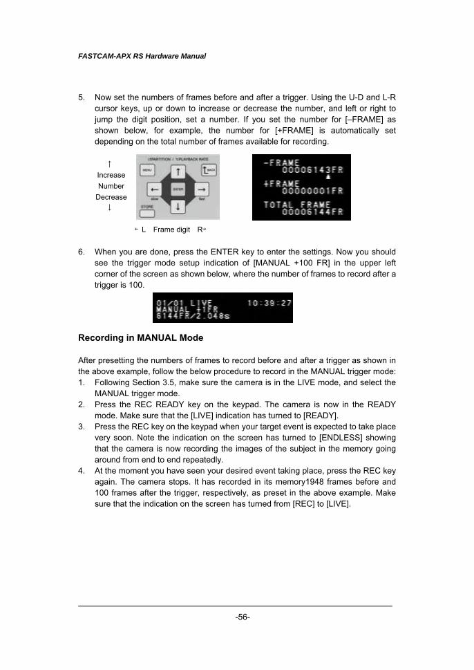
5. Now set the numbers of frames before and after a trigger. Using the U-D and L-R cursor keys, up or down to increase or decrease the number, and left or right to jump the digit position, set a number. If you set the number for [–FRAME] as shown below, for example, the number for [+FRAME] is automatically set depending on the total number of frames available for recording.
6. When you are done, press the ENTER key to enter the settings. Now you should
see the trigger mode setup indication of [MANUAL +100 FR] in the upper left corner of the screen as shown below, where the number of frames to record after a trigger is 100.
Recording in MANUAL Mode After presetting the numbers of frames to record before and after a trigger as shown in the above example, follow the below procedure to record in the MANUAL trigger mode: 1. Following Section 3.5, make sure the camera is in the LIVE mode, and select the
MANUAL trigger mode. 2. Press the REC READY key on the keypad. The camera is now in the READY
mode. Make sure that the [LIVE] indication has turned to [READY]. 3. Press the REC key on the keypad when your target event is expected to take place
very soon. Note the indication on the screen has turned to [ENDLESS] showing that the camera is now recording the images of the subject in the memory going around from end to end repeatedly.
4. At the moment you have seen your desired event taking place, press the REC key again. The camera stops. It has recorded in its memory1948 frames before and 100 frames after the trigger, respectively, as preset in the above example. Make sure that the indication on the screen has turned from [REC] to [LIVE].
↑ IncreaseNumber
Decrease↓
←L Frame digit R→
FASTCAM-APX RS Hardware Manual
-57-
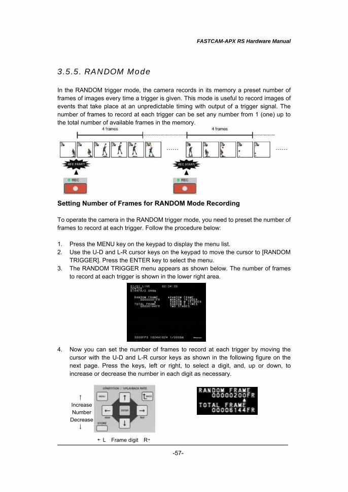
3.5.5. RANDOM Mode In the RANDOM trigger mode, the camera records in its memory a preset number of frames of images every time a trigger is given. This mode is useful to record images of events that take place at an unpredictable timing with output of a trigger signal. The number of frames to record at each trigger can be set any number from 1 (one) up to the total number of available frames in the memory. Setting Number of Frames for RANDOM Mode Recording To operate the camera in the RANDOM trigger mode, you need to preset the number of frames to record at each trigger. Follow the procedure below: 1. Press the MENU key on the keypad to display the menu list. 2. Use the U-D and L-R cursor keys on the keypad to move the cursor to [RANDOM
TRIGGER]. Press the ENTER key to select the menu. 3. The RANDOM TRIGGER menu appears as shown below. The number of frames
to record at each trigger is shown in the lower right area. 4. Now you can set the number of frames to record at each trigger by moving the
cursor with the U-D and L-R cursor keys as shown in the following figure on the next page. Press the keys, left or right, to select a digit, and, up or down, to increase or decrease the number in each digit as necessary.
↑ IncreaseNumber
Decrease↓
←L Frame digit R→
FASTCAM-APX RS Hardware Manual
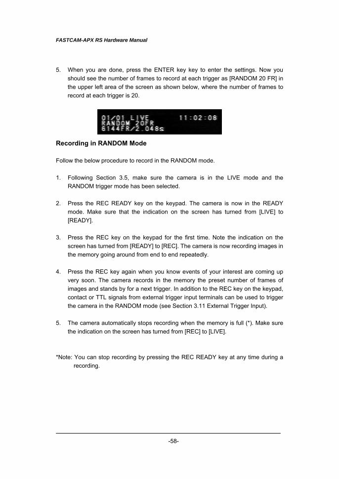
-58-
5. When you are done, press the ENTER key key to enter the settings. Now you should see the number of frames to record at each trigger as [RANDOM 20 FR] in the upper left area of the screen as shown below, where the number of frames to record at each trigger is 20.
Recording in RANDOM Mode Follow the below procedure to record in the RANDOM mode. 1. Following Section 3.5, make sure the camera is in the LIVE mode and the
RANDOM trigger mode has been selected. 2. Press the REC READY key on the keypad. The camera is now in the READY
mode. Make sure that the indication on the screen has turned from [LIVE] to [READY].
3. Press the REC key on the keypad for the first time. Note the indication on the
screen has turned from [READY] to [REC]. The camera is now recording images in the memory going around from end to end repeatedly.
4. Press the REC key again when you know events of your interest are coming up
very soon. The camera records in the memory the preset number of frames of images and stands by for a next trigger. In addition to the REC key on the keypad, contact or TTL signals from external trigger input terminals can be used to trigger the camera in the RANDOM mode (see Section 3.11 External Trigger Input).
5. The camera automatically stops recording when the memory is full (*). Make sure
the indication on the screen has turned from [REC] to [LIVE]. *Note: You can stop recording by pressing the REC READY key at any time during a
recording.
FASTCAM-APX RS Hardware Manual
-59-
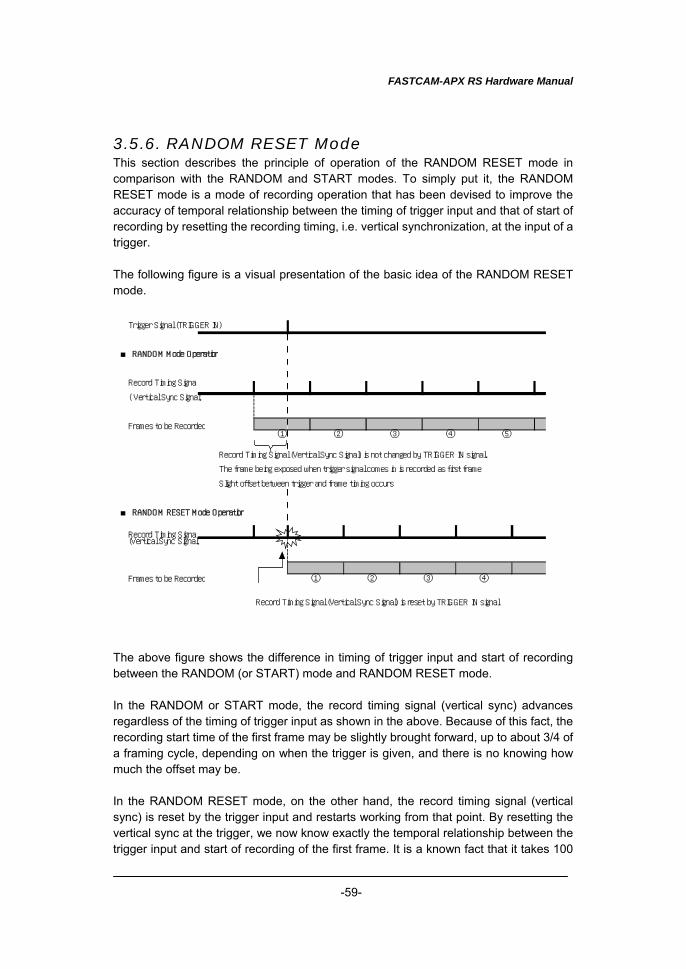
3.5.6. RANDOM RESET Mode This section describes the principle of operation of the RANDOM RESET mode in comparison with the RANDOM and START modes. To simply put it, the RANDOM RESET mode is a mode of recording operation that has been devised to improve the accuracy of temporal relationship between the timing of trigger input and that of start of recording by resetting the recording timing, i.e. vertical synchronization, at the input of a trigger. The following figure is a visual presentation of the basic idea of the RANDOM RESET mode. The above figure shows the difference in timing of trigger input and start of recording between the RANDOM (or START) mode and RANDOM RESET mode. In the RANDOM or START mode, the record timing signal (vertical sync) advances regardless of the timing of trigger input as shown in the above. Because of this fact, the recording start time of the first frame may be slightly brought forward, up to about 3/4 of a framing cycle, depending on when the trigger is given, and there is no knowing how much the offset may be. In the RANDOM RESET mode, on the other hand, the record timing signal (vertical sync) is reset by the trigger input and restarts working from that point. By resetting the vertical sync at the trigger, we now know exactly the temporal relationship between the trigger input and start of recording of the first frame. It is a known fact that it takes 100
Trigger Signal (TRIGGER IN) ■ RANDOM Mode Operation
Record Timing Signal
( Vertical Sync Signal)
Frames to be Recorded① ② ③ ④ ⑤
Record Timing Signal (Vertical Sync Signal) is not changed by TRIGGER IN signal.
The frame being exposed when trigger signal comes in is recorded as first frame.
Slight offset between trigger and frame timing occurs.
■ RANDOM RESET Mode Operation
Record Timing Signal(Vertical Sync Signal)
Frames to be Recorded ① ② ③ ④ Record Timing Signal (Vertical Sync Signal) is reset by TRIGGER IN signal.
FASTCAM-APX RS Hardware Manual
-60-
ns from the input of a trigger signal to reset of the vertical sync signal, i.e. start of recording. Note: Technically, there is a slight time lag between the record timing (vertical sync)
and start of exposure, which is dependant on the framing rate being used (7.4 us at 2,000 fps).
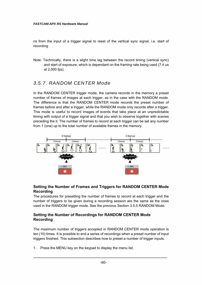
3.5.7. RANDOM CENTER Mode In the RANDOM CENTER trigger mode, the camera records in the memory a preset number of frames of images at each trigger, as in the case with the RANDOM mode. The difference is that the RANDOM CENTER mode records the preset number of frames before and after a trigger, while the RANDOM mode only records after a trigger. This mode is useful to record images of events that take place at an unpredictable timing with output of a trigger signal and that you wish to observe together with scenes preceding the it. The number of frames to record at each trigger can be set any number from 1 (one) up to the total number of available frames in the memory. Setting the Number of Frames and Triggers for RANDOM CENTER Mode Recording The procedures for presetting the number of frames to record at each trigger and the number of triggers to be given during a recording session are the same as the ones used in the RANDOM trigger mode. See the previous Section 3.5.5 RANDOM Mode. Setting the Number of Recordings for RANDOM CENTER Mode Recording The maximum number of triggers accepted in RANDOM CENTER mode operation is ten (10) times. It is possible to end a series of recordings when a preset number of input triggers finished. This subsection describes how to preset a number of trigger inputs. 1. Press the MENU key on the keypad to display the menu list.
FASTCAM-APX RS Hardware Manual
-61-
2. Move the cursor to [RANDOM E TIMES] and press the ENTER key to set the selection.
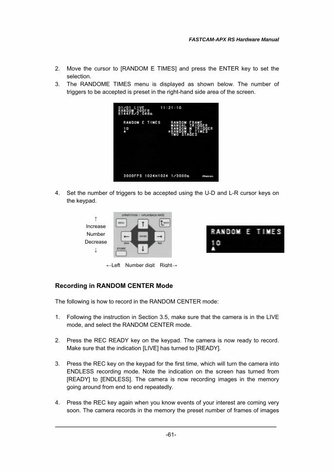
3. The RANDOME TIMES menu is displayed as shown below. The number of triggers to be accepted is preset in the right-hand side area of the screen.
4. Set the number of triggers to be accepted using the U-D and L-R cursor keys on
the keypad. Recording in RANDOM CENTER Mode The following is how to record in the RANDOM CENTER mode: 1. Following the instruction in Section 3.5, make sure that the camera is in the LIVE
mode, and select the RANDOM CENTER mode. 2. Press the REC READY key on the keypad. The camera is now ready to record.
Make sure that the indication [LIVE] has turned to [READY]. 3. Press the REC key on the keypad for the first time, which will turn the camera into
ENDLESS recording mode. Note the indication on the screen has turned from [READY] to [ENDLESS]. The camera is now recording images in the memory going around from end to end repeatedly.
4. Press the REC key again when you know events of your interest are coming very
soon. The camera records in the memory the preset number of frames of images
↑ IncreaseNumber
Decrease↓
←Left Number digit Right→
FASTCAM-APX RS Hardware Manual
-62-
before and after the event, and stands by for a next trigger. In addition to the REC key on the keypad, contact or TTL signals from external trigger input terminals can be used to trigger the camera in the RANDOM mode (see Section 3.11 External Trigger Input).
5. The camera automatically stops recording when the memory is full (*). Make sure
the indication on the screen has turned from [ENDLESS] to [LIVE]. *Note: You can stop recording by pressing the REC READY key at any time during a
recording session.
FASTCAM-APX RS Hardware Manual
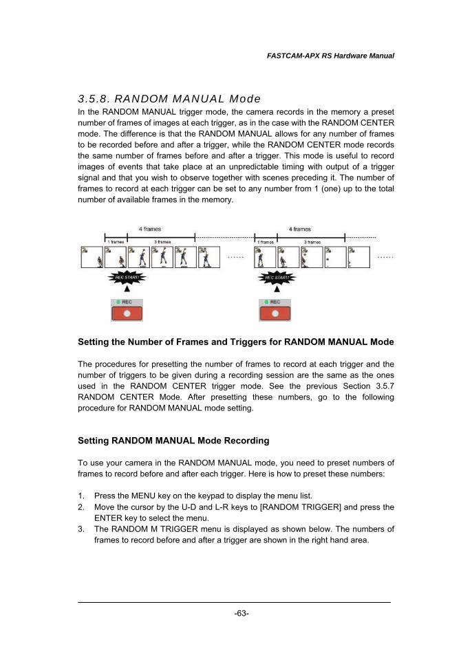
-63-
3.5.8. RANDOM MANUAL Mode In the RANDOM MANUAL trigger mode, the camera records in the memory a preset number of frames of images at each trigger, as in the case with the RANDOM CENTER mode. The difference is that the RANDOM MANUAL allows for any number of frames to be recorded before and after a trigger, while the RANDOM CENTER mode records the same number of frames before and after a trigger. This mode is useful to record images of events that take place at an unpredictable timing with output of a trigger signal and that you wish to observe together with scenes preceding it. The number of frames to record at each trigger can be set to any number from 1 (one) up to the total number of available frames in the memory. Setting the Number of Frames and Triggers for RANDOM MANUAL Mode The procedures for presetting the number of frames to record at each trigger and the number of triggers to be given during a recording session are the same as the ones used in the RANDOM CENTER trigger mode. See the previous Section 3.5.7 RANDOM CENTER Mode. After presetting these numbers, go to the following procedure for RANDOM MANUAL mode setting. Setting RANDOM MANUAL Mode Recording To use your camera in the RANDOM MANUAL mode, you need to preset numbers of frames to record before and after each trigger. Here is how to preset these numbers: 1. Press the MENU key on the keypad to display the menu list. 2. Move the cursor by the U-D and L-R keys to [RANDOM TRIGGER] and press the
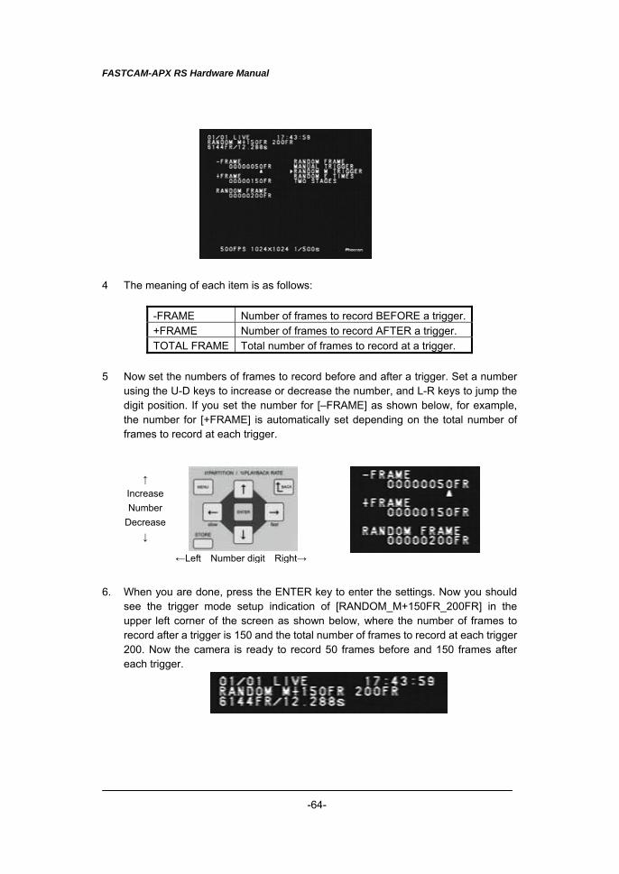
ENTER key to select the menu. 3. The RANDOM M TRIGGER menu is displayed as shown below. The numbers of
frames to record before and after a trigger are shown in the right hand area.
FASTCAM-APX RS Hardware Manual
-64-
4 The meaning of each item is as follows:
-FRAME Number of frames to record BEFORE a trigger. +FRAME Number of frames to record AFTER a trigger. TOTAL FRAME Total number of frames to record at a trigger.
5 Now set the numbers of frames to record before and after a trigger. Set a number
using the U-D keys to increase or decrease the number, and L-R keys to jump the digit position. If you set the number for [–FRAME] as shown below, for example, the number for [+FRAME] is automatically set depending on the total number of frames to record at each trigger.
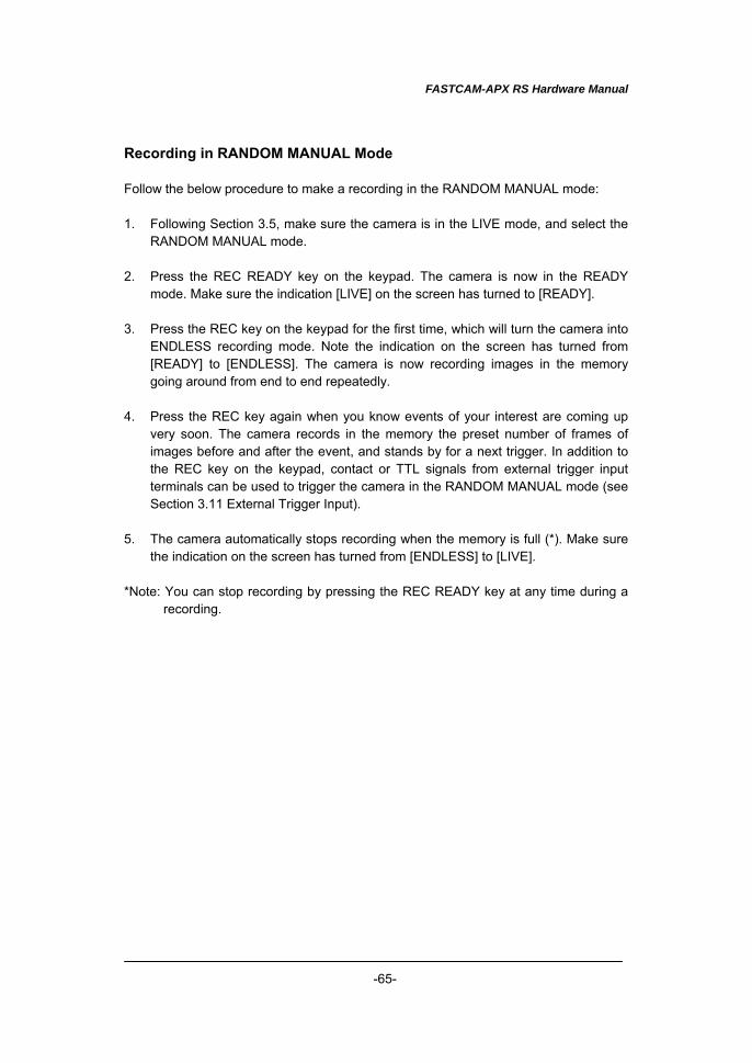
6. When you are done, press the ENTER key to enter the settings. Now you should
see the trigger mode setup indication of [RANDOM_M+150FR_200FR] in the upper left corner of the screen as shown below, where the number of frames to record after a trigger is 150 and the total number of frames to record at each trigger 200. Now the camera is ready to record 50 frames before and 150 frames after each trigger.
↑ IncreaseNumber
Decrease↓
←Left Number digit Right→
FASTCAM-APX RS Hardware Manual
-65-
Recording in RANDOM MANUAL Mode Follow the below procedure to make a recording in the RANDOM MANUAL mode: 1. Following Section 3.5, make sure the camera is in the LIVE mode, and select the
RANDOM MANUAL mode. 2. Press the REC READY key on the keypad. The camera is now in the READY
mode. Make sure the indication [LIVE] on the screen has turned to [READY]. 3. Press the REC key on the keypad for the first time, which will turn the camera into
ENDLESS recording mode. Note the indication on the screen has turned from [READY] to [ENDLESS]. The camera is now recording images in the memory going around from end to end repeatedly.
4. Press the REC key again when you know events of your interest are coming up
very soon. The camera records in the memory the preset number of frames of images before and after the event, and stands by for a next trigger. In addition to the REC key on the keypad, contact or TTL signals from external trigger input terminals can be used to trigger the camera in the RANDOM MANUAL mode (see Section 3.11 External Trigger Input).
5. The camera automatically stops recording when the memory is full (*). Make sure
the indication on the screen has turned from [ENDLESS] to [LIVE]. *Note: You can stop recording by pressing the REC READY key at any time during a
recording.
FASTCAM-APX RS Hardware Manual
-66-
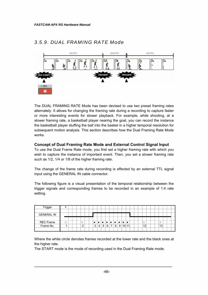
3.5.9. DUAL FRAMING RATE Mode The DUAL FRAMING RATE Mode has been devised to use two preset framing rates alternately. It allows for changing the framing rate during a recording to capture faster or more interesting events for slower playback. For example, while shooting, at a slower framing rate, a basketball player nearing the goal, you can record the instance the basketball player stuffing the ball into the basket in a higher temporal resolution for subsequent motion analysis. This section describes how the Dual Framing Rate Mode works. Concept of Dual Framing Rate Mode and External Control Signal Input To use the Dual Frame Rate mode, you first set a higher framing rate with which you wish to capture the instance of important event. Then, you set a slower framing rate such as 1/2, 1/4 or 1/8 of the higher framing rate. The change of the frame rate during recording is effected by an external TTL signal input using the GENERAL IN cable connector. The following figure is a visual presentation of the temporal relationship between the trigger signals and corresponding frames to be recorded in an example of 1:4 rate setting. .
Trigger ▼
GENERAL IN
REC Frame ○ ○ ● ● ● ● ● ● ● ● ● ○ ○Frame No. 1 2 3 4 5 6 7 8 9 10 11 12 13
Where the white circle denotes frames recorded at the lower rate and the black ones at the higher rate. The START mode is the mode of recording used in the Dual Framing Rate mode.
FASTCAM-APX RS Hardware Manual
-67-
TTL change over signals, to be fed to the GENERAL IN connector, are defined as follows (e.g. for positive signal setting):
GENERAL_IN Input “H” Change to higher rate from the next frame GENERAL_IN Input “L” Change to lower rate from the next frame
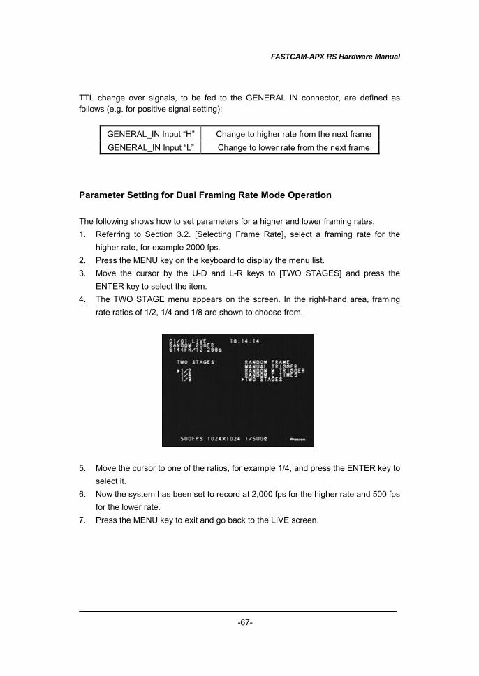
Parameter Setting for Dual Framing Rate Mode Operation The following shows how to set parameters for a higher and lower framing rates. 1. Referring to Section 3.2. [Selecting Frame Rate], select a framing rate for the
higher rate, for example 2000 fps. 2. Press the MENU key on the keyboard to display the menu list. 3. Move the cursor by the U-D and L-R keys to [TWO STAGES] and press the
ENTER key to select the item. 4. The TWO STAGE menu appears on the screen. In the right-hand area, framing
rate ratios of 1/2, 1/4 and 1/8 are shown to choose from. 5. Move the cursor to one of the ratios, for example 1/4, and press the ENTER key to
select it. 6. Now the system has been set to record at 2,000 fps for the higher rate and 500 fps
for the lower rate. 7. Press the MENU key to exit and go back to the LIVE screen.
FASTCAM-APX RS Hardware Manual
-68-
Recording in Dual Framing Rate Mode Follow the below procedure to record in the Dual Framing Rate mode. 1. Referring to Section 3.5. Selecting Trigger Mode, make sure the camera is in the
LIVE mode and the trigger mode is TWO STAGES. 2. Connect a TTL trigger input to the GENERAL IN connector. See the table below for
TTL signal and recording frame rate (e.g. for positive signal setting):
GENERAL_IN Input “H” Change to higher rate from the next frame GENERAL_IN Input “L” Change to lower rate from the next frame
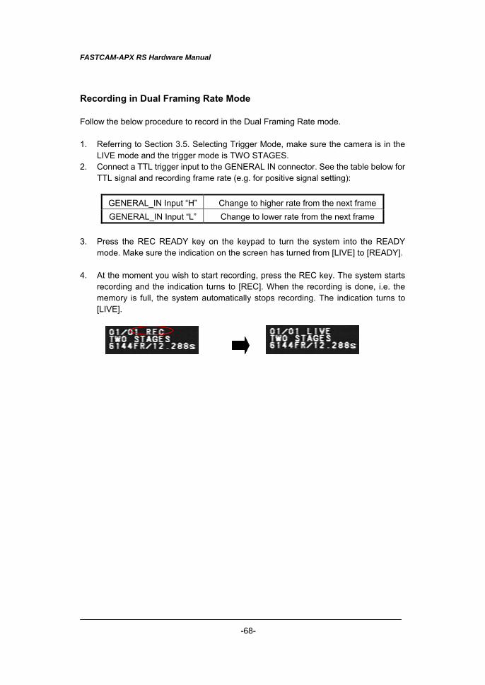
3. Press the REC READY key on the keypad to turn the system into the READY
mode. Make sure the indication on the screen has turned from [LIVE] to [READY]. 4. At the moment you wish to start recording, press the REC key. The system starts
recording and the indication turns to [REC]. When the recording is done, i.e. the memory is full, the system automatically stops recording. The indication turns to [LIVE].
FASTCAM-APX RS Hardware Manual
-69-
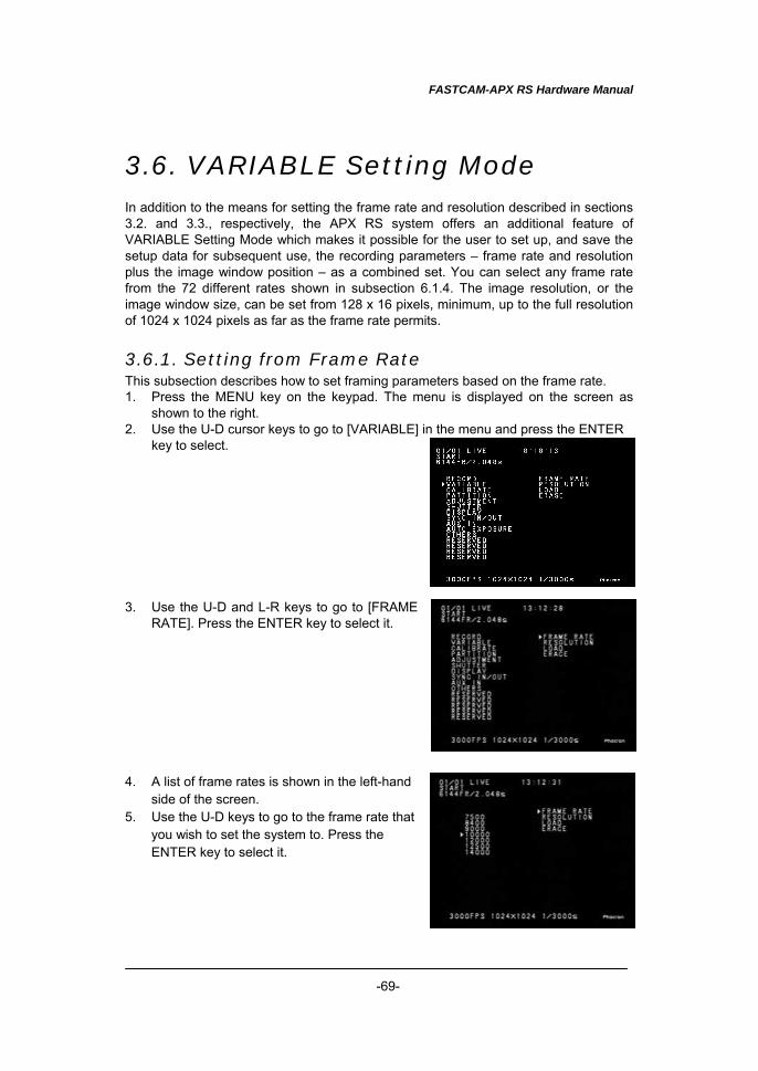
3.6. VARIABLE Setting Mode In addition to the means for setting the frame rate and resolution described in sections 3.2. and 3.3., respectively, the APX RS system offers an additional feature of VARIABLE Setting Mode which makes it possible for the user to set up, and save the setup data for subsequent use, the recording parameters – frame rate and resolution plus the image window position – as a combined set. You can select any frame rate from the 72 different rates shown in subsection 6.1.4. The image resolution, or the image window size, can be set from 128 x 16 pixels, minimum, up to the full resolution of 1024 x 1024 pixels as far as the frame rate permits.
3.6.1. Setting from Frame Rate This subsection describes how to set framing parameters based on the frame rate. 1. Press the MENU key on the keypad. The menu is displayed on the screen as
shown to the right. 2. Use the U-D cursor keys to go to [VARIABLE] in the menu and press the ENTER
key to select. 3. Use the U-D and L-R keys to go to [FRAME
RATE]. Press the ENTER key to select it. 4. A list of frame rates is shown in the left-hand
side of the screen. 5. Use the U-D keys to go to the frame rate that
you wish to set the system to. Press the ENTER key to select it.
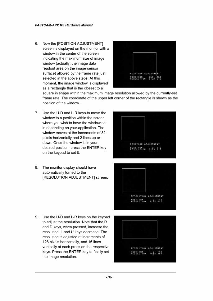
FASTCAM-APX RS Hardware Manual
-70-
6. Now the [POSITION ADJUSTMENT] screen is displayed on the monitor with a window in the center of the screen indicating the maximum size of image window (actually, the image data readout area on the image sensor surface) allowed by the frame rate just selected in the above steps. At this moment, the image window is displayed as a rectangle that is the closest to a square in shape within the maximum image resolution allowed by the currently-set frame rate. The coordinate of the upper left corner of the rectangle is shown as the position of the window.
7. Use the U-D and L-R keys to move the
window to a position within the screen where you wish to have the window set in depending on your application. The window moves at the increments of 32 pixels horizontally and 2 lines up or down. Once the window is in your desired position, press the ENTER key on the keypad to set it.
8. The monitor display should have
automatically turned to the [RESOLUTION ADJUSTMENT] screen.
9. Use the U-D and L-R keys on the keypad
to adjust the resolution. Note that the R and D keys, when pressed, increase the resolution; L and U keys decrease. The resolution is adjusted at increments of 128 pixels horizontally, and 16 lines vertically at each press on the respective keys. Press the ENTER key to finally set the image resolution.
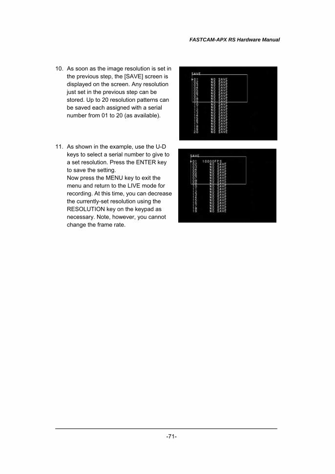
FASTCAM-APX RS Hardware Manual
-71-
10. As soon as the image resolution is set in the previous step, the [SAVE] screen is displayed on the screen. Any resolution just set in the previous step can be stored. Up to 20 resolution patterns can be saved each assigned with a serial number from 01 to 20 (as available).
11. As shown in the example, use the U-D
keys to select a serial number to give to a set resolution. Press the ENTER key to save the setting. Now press the MENU key to exit the menu and return to the LIVE mode for recording. At this time, you can decrease the currently-set resolution using the RESOLUTION key on the keypad as necessary. Note, however, you cannot change the frame rate.
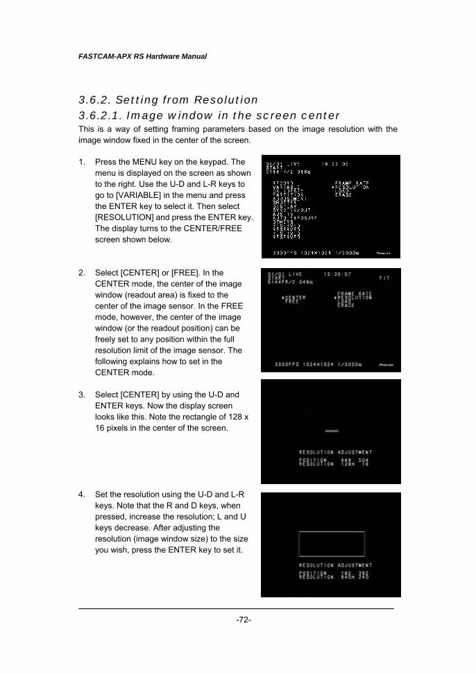
FASTCAM-APX RS Hardware Manual
-72-
3.6.2. Setting from Resolution 3.6.2.1. Image window in the screen center This is a way of setting framing parameters based on the image resolution with the image window fixed in the center of the screen. 1. Press the MENU key on the keypad. The
menu is displayed on the screen as shown to the right. Use the U-D and L-R keys to go to [VARIABLE] in the menu and press the ENTER key to select it. Then select [RESOLUTION] and press the ENTER key. The display turns to the CENTER/FREE screen shown below.
2. Select [CENTER] or [FREE]. In the
CENTER mode, the center of the image window (readout area) is fixed to the center of the image sensor. In the FREE mode, however, the center of the image window (or the readout position) can be freely set to any position within the full resolution limit of the image sensor. The following explains how to set in the CENTER mode.
3. Select [CENTER] by using the U-D and
ENTER keys. Now the display screen looks like this. Note the rectangle of 128 x 16 pixels in the center of the screen.
4. Set the resolution using the U-D and L-R
keys. Note that the R and D keys, when pressed, increase the resolution; L and U keys decrease. After adjusting the resolution (image window size) to the size you wish, press the ENTER key to set it.
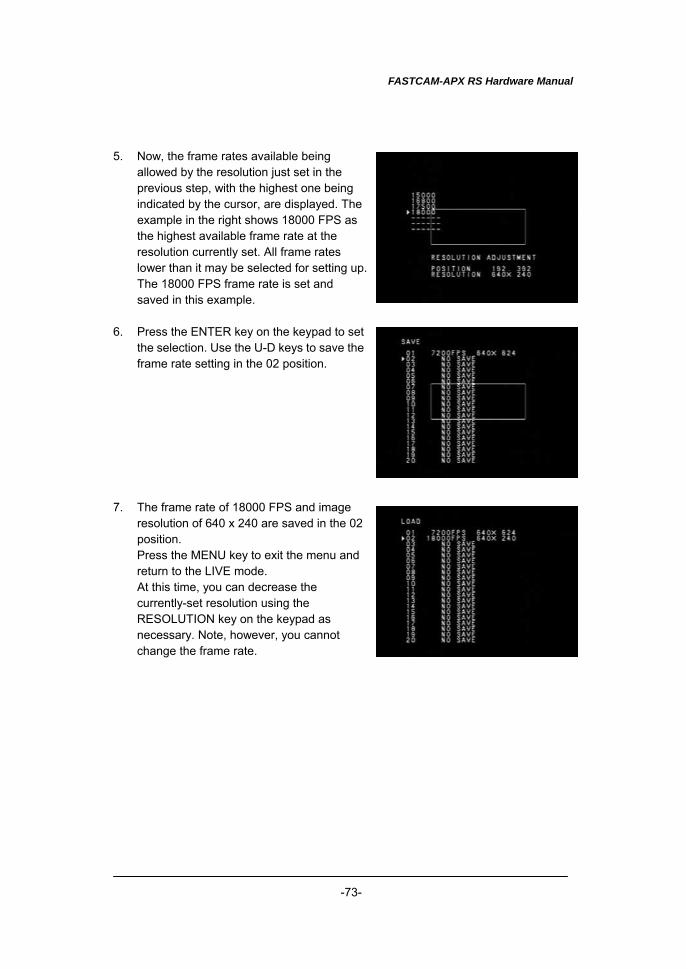
FASTCAM-APX RS Hardware Manual
-73-
5. Now, the frame rates available being
allowed by the resolution just set in the previous step, with the highest one being indicated by the cursor, are displayed. The example in the right shows 18000 FPS as the highest available frame rate at the resolution currently set. All frame rates lower than it may be selected for setting up. The 18000 FPS frame rate is set and saved in this example.
6. Press the ENTER key on the keypad to set
the selection. Use the U-D keys to save the frame rate setting in the 02 position.
7. The frame rate of 18000 FPS and image
resolution of 640 x 240 are saved in the 02 position. Press the MENU key to exit the menu and return to the LIVE mode. At this time, you can decrease the currently-set resolution using the RESOLUTION key on the keypad as necessary. Note, however, you cannot change the frame rate.
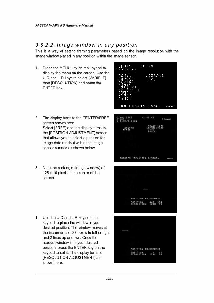
FASTCAM-APX RS Hardware Manual
-74-
3.6.2.2. Image window in any position This is a way of setting framing parameters based on the image resolution with the image window placed in any position within the image sensor.
1. Press the MENU key on the keypad to
display the menu on the screen. Use the U-D and L-R keys to select [VARIBLE] then [RESOLUTION] and press the ENTER key.
2. The display turns to the CENTER/FREE
screen shown here. Select [FREE] and the display turns to the [POSITION ADJUSTMENT] screen that allows you to select a position for image data readout within the image sensor surface as shown below.
3. Note the rectangle (image window) of
128 x 16 pixels in the center of the screen.
4. Use the U-D and L-R keys on the
keypad to place the window in your desired position. The window moves at the increments of 32 pixels to left or right and 2 lines up or down. Once the readout window is in your desired position, press the ENTER key on the keypad to set it. The display turns to [RESOLUTION ADJUSTMENT] as shown here.
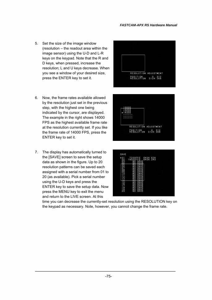
FASTCAM-APX RS Hardware Manual
-75-
5. Set the size of the image window (resolution – the readout area within the image sensor) using the U-D and L-R keys on the keypad. Note that the R and D keys, when pressed, increase the resolution; L and U keys decrease. When you see a window of your desired size, press the ENTER key to set it.
6. Now, the frame rates available allowed
by the resolution just set in the previous step, with the highest one being indicated by the cursor, are displayed. The example in the right shows 14000 FPS as the highest available frame rate at the resolution currently set. If you like the frame rate of 14000 FPS, press the ENTER key to set it.
7. The display has automatically turned to
the [SAVE] screen to save the setup data as shown in the figure. Up to 20 resolution patterns can be saved each assigned with a serial number from 01 to 20 (as available). Pick a serial number using the U-D keys and press the ENTER key to save the setup data. Now press the MENU key to exit the menu and return to the LIVE screen. At this time you can decrease the currently-set resolution using the RESOLUTION key on the keypad as necessary. Note, however, you cannot change the frame rate.
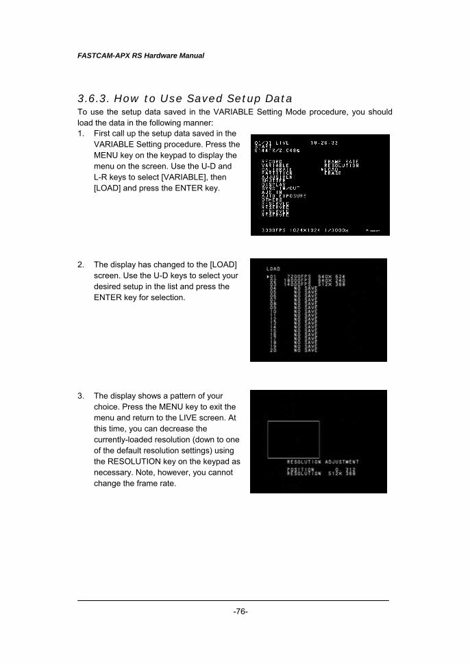
FASTCAM-APX RS Hardware Manual
-76-
3.6.3. How to Use Saved Setup Data To use the setup data saved in the VARIABLE Setting Mode procedure, you should load the data in the following manner: 1. First call up the setup data saved in the
VARIABLE Setting procedure. Press the MENU key on the keypad to display the menu on the screen. Use the U-D and L-R keys to select [VARIABLE], then [LOAD] and press the ENTER key.
2. The display has changed to the [LOAD]
screen. Use the U-D keys to select your desired setup in the list and press the ENTER key for selection.
3. The display shows a pattern of your
choice. Press the MENU key to exit the menu and return to the LIVE screen. At this time, you can decrease the currently-loaded resolution (down to one of the default resolution settings) using the RESOLUTION key on the keypad as necessary. Note, however, you cannot change the frame rate.
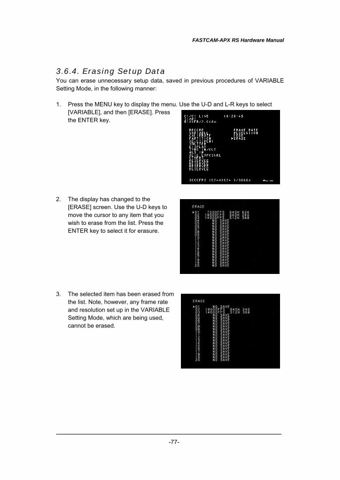
FASTCAM-APX RS Hardware Manual
-77-
3.6.4. Erasing Setup Data You can erase unnecessary setup data, saved in previous procedures of VARIABLE Setting Mode, in the following manner: 1. Press the MENU key to display the menu. Use the U-D and L-R keys to select
[VARIABLE], and then [ERASE]. Press the ENTER key.
2. The display has changed to the
[ERASE] screen. Use the U-D keys to move the cursor to any item that you wish to erase from the list. Press the ENTER key to select it for erasure.
3. The selected item has been erased from
the list. Note, however, any frame rate and resolution set up in the VARIABLE Setting Mode, which are being used, cannot be erased.
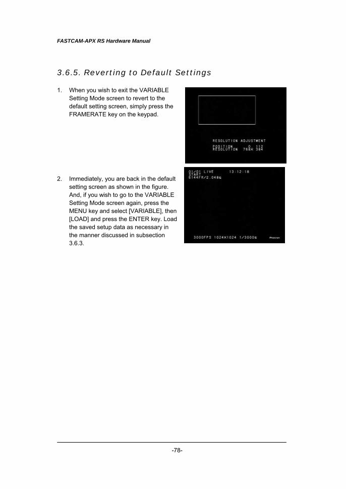
FASTCAM-APX RS Hardware Manual
-78-
3.6.5. Reverting to Default Settings 1. When you wish to exit the VARIABLE
Setting Mode screen to revert to the default setting screen, simply press the FRAMERATE key on the keypad.
2. Immediately, you are back in the default
setting screen as shown in the figure. And, if you wish to go to the VARIABLE Setting Mode screen again, press the MENU key and select [VARIABLE], then [LOAD] and press the ENTER key. Load the saved setup data as necessary in the manner discussed in subsection 3.6.3.
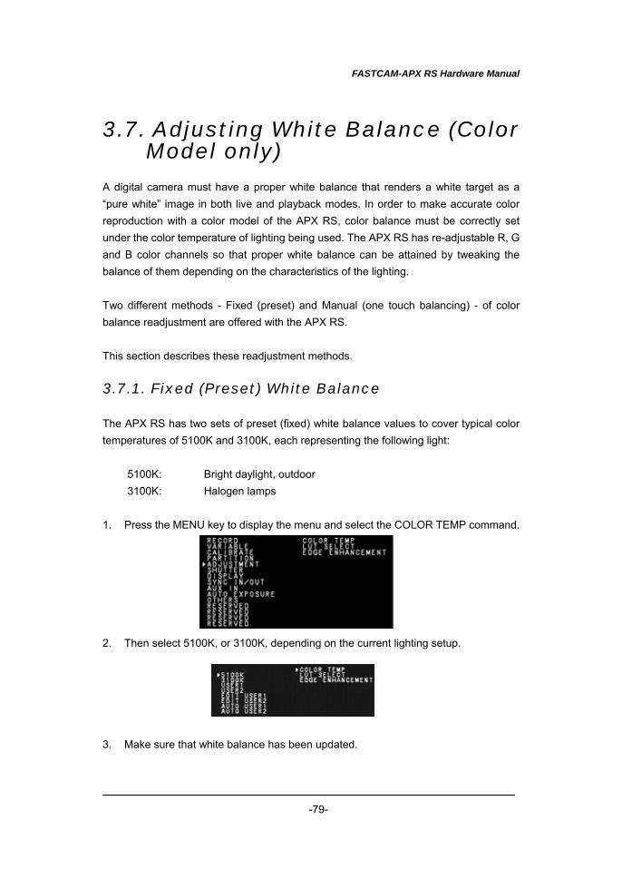
FASTCAM-APX RS Hardware Manual
-79-
3.7. Adjusting White Balance (Color Model only)
A digital camera must have a proper white balance that renders a white target as a “pure white” image in both live and playback modes. In order to make accurate color reproduction with a color model of the APX RS, color balance must be correctly set under the color temperature of lighting being used. The APX RS has re-adjustable R, G and B color channels so that proper white balance can be attained by tweaking the balance of them depending on the characteristics of the lighting. Two different methods - Fixed (preset) and Manual (one touch balancing) - of color balance readjustment are offered with the APX RS. This section describes these readjustment methods. 3.7.1. Fixed (Preset) White Balance The APX RS has two sets of preset (fixed) white balance values to cover typical color temperatures of 5100K and 3100K, each representing the following light:
5100K: Bright daylight, outdoor 3100K: Halogen lamps
1. Press the MENU key to display the menu and select the COLOR TEMP command. 2. Then select 5100K, or 3100K, depending on the current lighting setup. 3. Make sure that white balance has been updated.

FASTCAM-APX RS Hardware Manual
-80-
3.7.2. Manual (One Touch) White Balance To obtain a better white balance, the APX RS has a means for setting up white balance semi-automatically. Two patterns of setting can be saved in memory as preset parameters. Follow the below procedure: 1. Set up parameters for an upcoming recording – frame rate, shutter speed and
resolution. 2. Press the MENU key on the keypad to display the menu list. 3. Move the cursor to the [COLOR TEMP] command using the U-D and L-R keys. 4. Press the EMTER key and the COLOR TEMP menu appears as shown below. 5. Move the cursor by the U-D and L-R keys to AUTO USER1 (or AUTO USER2)
and press the ENTER key to enter the white balance readjustment mode. 6. Make sure that the value of each of R, G and B channels and indication of DARK
or GRIGHT are shown in the lower left corner of the screen. 7. Turn the light on and shoot a piece of white paper or something that is going to be
the reference white target, and place it in the center of the picture frame. 8. Control the lens iris to readjust the amount of incoming light onto the imaging
sensor. While doing this, make sure that the indicator changes from [DARK] to [PUSH ENTER] to [BRIGHT], or other way around, as the incoming light amount varies. If the indication does not change even when the overall brightness of the image frame is changing, check if the white target is in the center part of the view field. If the target is not in the center, replace it until the indicator changes to the movement of the iris.
9. Control the iris until the indicator shows PUSH ENTER. 10. Press the ENTER key to enter the current setting of white balance while PUSH
ENTER is displayed. 11. Now the APX RS system has obtained a set of R, G and B values for a proper
white balance. Make sure that the displayed image has been updated. 12. The set of R, G and B values are saved in the USER 1 (or USER 2) window.
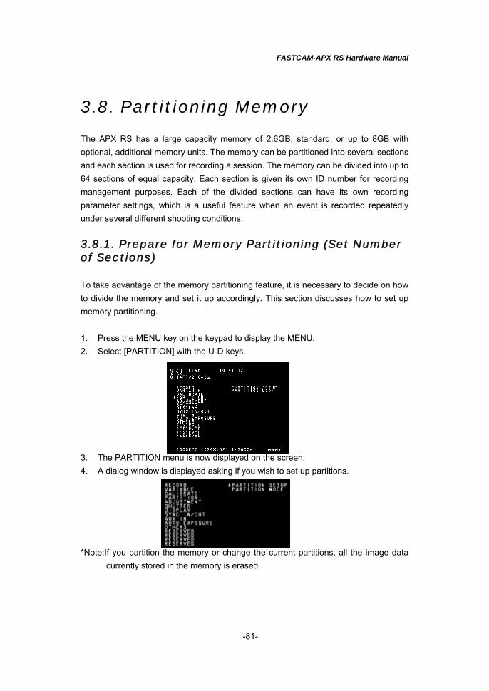
FASTCAM-APX RS Hardware Manual
-81-
3.8. Partitioning Memory The APX RS has a large capacity memory of 2.6GB, standard, or up to 8GB with optional, additional memory units. The memory can be partitioned into several sections and each section is used for recording a session. The memory can be divided into up to 64 sections of equal capacity. Each section is given its own ID number for recording management purposes. Each of the divided sections can have its own recording parameter settings, which is a useful feature when an event is recorded repeatedly under several different shooting conditions. 3.8.1. Prepare for Memory Partitioning (Set Number of Sections) To take advantage of the memory partitioning feature, it is necessary to decide on how to divide the memory and set it up accordingly. This section discusses how to set up memory partitioning. 1. Press the MENU key on the keypad to display the MENU. 2. Select [PARTITION] with the U-D keys. 3. The PARTITION menu is now displayed on the screen. 4. A dialog window is displayed asking if you wish to set up partitions. *Note:If you partition the memory or change the current partitions, all the image data
currently stored in the memory is erased.
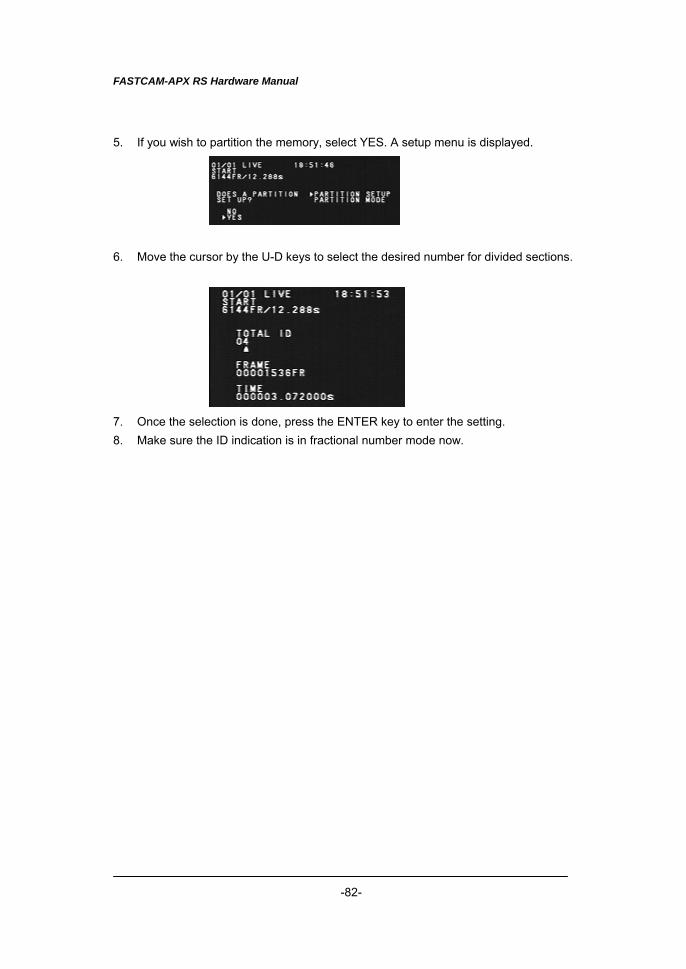
FASTCAM-APX RS Hardware Manual
-82-
5. If you wish to partition the memory, select YES. A setup menu is displayed. 6. Move the cursor by the U-D keys to select the desired number for divided sections. 7. Once the selection is done, press the ENTER key to enter the setting. 8. Make sure the ID indication is in fractional number mode now.
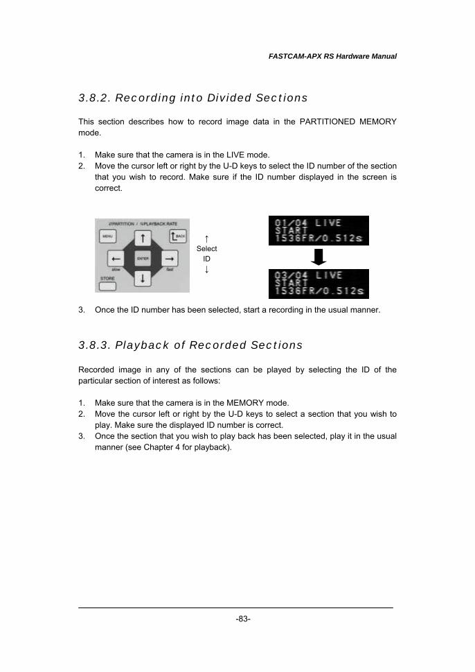
FASTCAM-APX RS Hardware Manual
-83-
3.8.2. Recording into Divided Sections This section describes how to record image data in the PARTITIONED MEMORY mode. 1. Make sure that the camera is in the LIVE mode. 2. Move the cursor left or right by the U-D keys to select the ID number of the section
that you wish to record. Make sure if the ID number displayed in the screen is correct.
3. Once the ID number has been selected, start a recording in the usual manner.
3.8.3. Playback of Recorded Sections Recorded image in any of the sections can be played by selecting the ID of the particular section of interest as follows: 1. Make sure that the camera is in the MEMORY mode. 2. Move the cursor left or right by the U-D keys to select a section that you wish to
play. Make sure the displayed ID number is correct. 3. Once the section that you wish to play back has been selected, play it in the usual
manner (see Chapter 4 for playback).
↑ Select
ID ↓
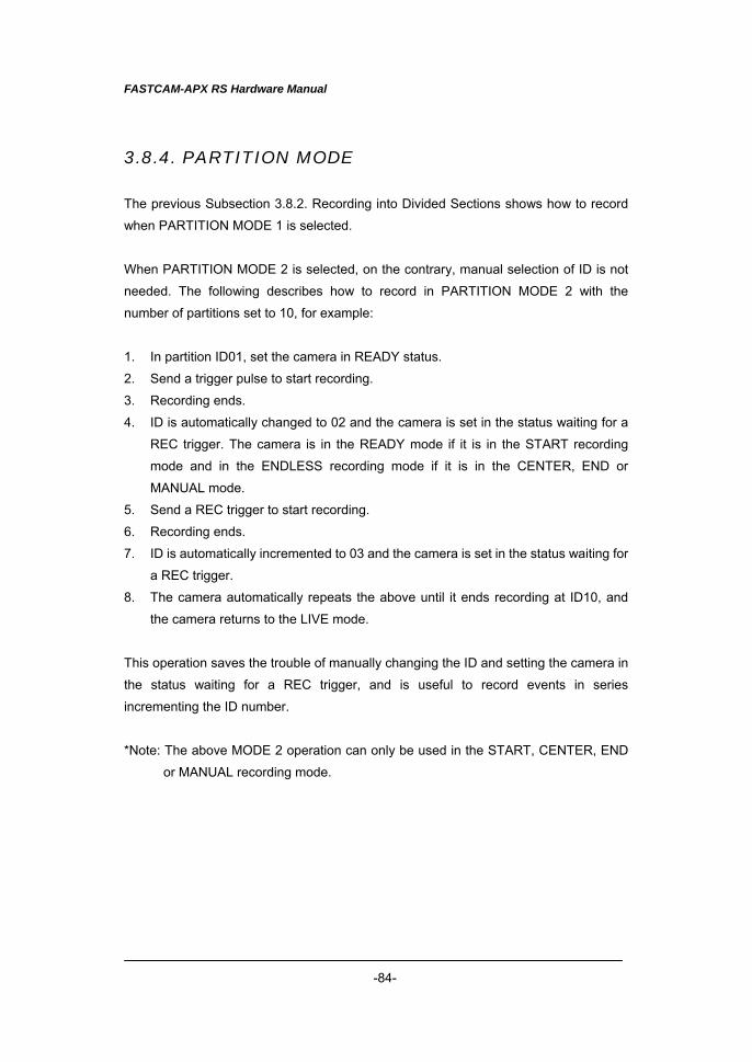
FASTCAM-APX RS Hardware Manual
-84-
3.8.4. PARTITION MODE
The previous Subsection 3.8.2. Recording into Divided Sections shows how to record
when PARTITION MODE 1 is selected.
When PARTITION MODE 2 is selected, on the contrary, manual selection of ID is not
needed. The following describes how to record in PARTITION MODE 2 with the
number of partitions set to 10, for example:
1. In partition ID01, set the camera in READY status.
2. Send a trigger pulse to start recording.
3. Recording ends.
4. ID is automatically changed to 02 and the camera is set in the status waiting for a
REC trigger. The camera is in the READY mode if it is in the START recording
mode and in the ENDLESS recording mode if it is in the CENTER, END or
MANUAL mode.
5. Send a REC trigger to start recording.
6. Recording ends.
7. ID is automatically incremented to 03 and the camera is set in the status waiting for
a REC trigger.
8. The camera automatically repeats the above until it ends recording at ID10, and
the camera returns to the LIVE mode.
This operation saves the trouble of manually changing the ID and setting the camera in
the status waiting for a REC trigger, and is useful to record events in series
incrementing the ID number.
*Note: The above MODE 2 operation can only be used in the START, CENTER, END
or MANUAL recording mode.
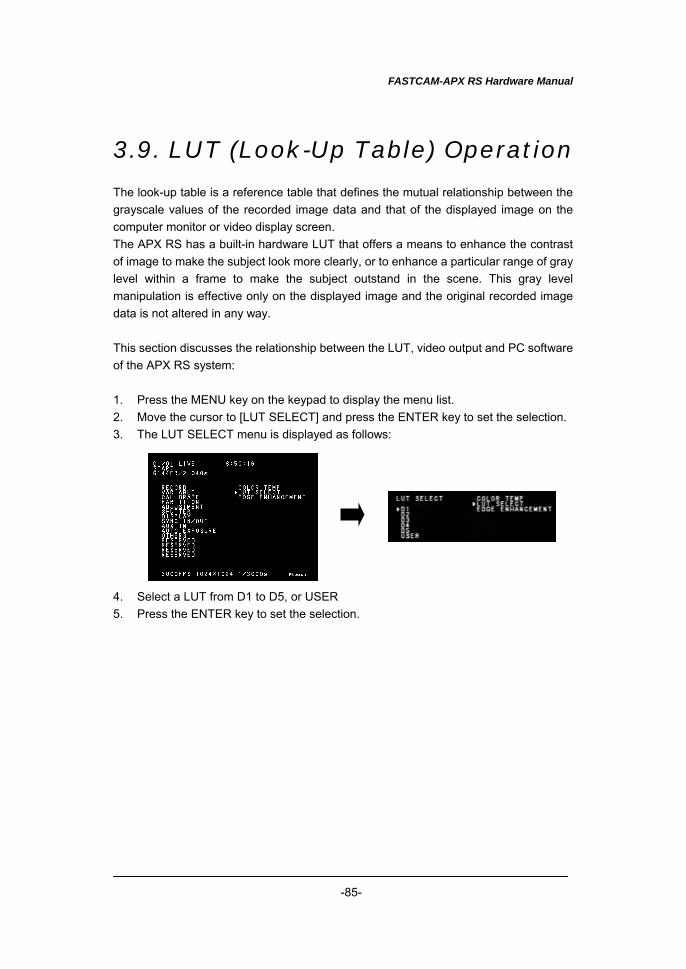
FASTCAM-APX RS Hardware Manual
-85-
3.9. LUT (Look-Up Table) Operation The look-up table is a reference table that defines the mutual relationship between the grayscale values of the recorded image data and that of the displayed image on the computer monitor or video display screen. The APX RS has a built-in hardware LUT that offers a means to enhance the contrast of image to make the subject look more clearly, or to enhance a particular range of gray level within a frame to make the subject outstand in the scene. This gray level manipulation is effective only on the displayed image and the original recorded image data is not altered in any way. This section discusses the relationship between the LUT, video output and PC software of the APX RS system: 1. Press the MENU key on the keypad to display the menu list. 2. Move the cursor to [LUT SELECT] and press the ENTER key to set the selection. 3. The LUT SELECT menu is displayed as follows: 4. Select a LUT from D1 to D5, or USER 5. Press the ENTER key to set the selection.
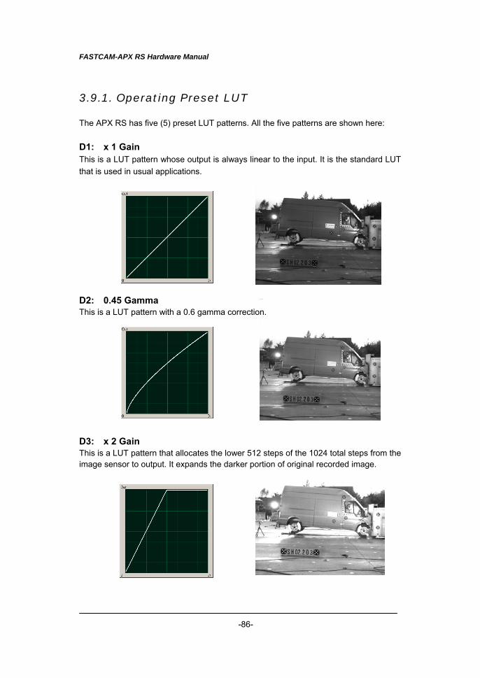
FASTCAM-APX RS Hardware Manual
-86-
3.9.1. Operating Preset LUT The APX RS has five (5) preset LUT patterns. All the five patterns are shown here: D1: x 1 Gain This is a LUT pattern whose output is always linear to the input. It is the standard LUT that is used in usual applications.
D2: 0.45 Gamma This is a LUT pattern with a 0.6 gamma correction.
D3: x 2 Gain This is a LUT pattern that allocates the lower 512 steps of the 1024 total steps from the image sensor to output. It expands the darker portion of original recorded image.
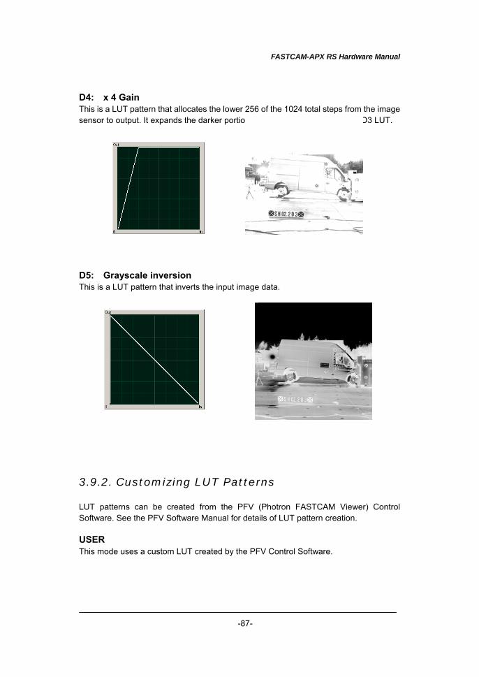
FASTCAM-APX RS Hardware Manual
-87-
D4: x 4 Gain This is a LUT pattern that allocates the lower 256 of the 1024 total steps from the image sensor to output. It expands the darker portion of image, more radically than D3 LUT.
D5: Grayscale inversion This is a LUT pattern that inverts the input image data.
3.9.2. Customizing LUT Patterns LUT patterns can be created from the PFV (Photron FASTCAM Viewer) Control Software. See the PFV Software Manual for details of LUT pattern creation. USER This mode uses a custom LUT created by the PFV Control Software.
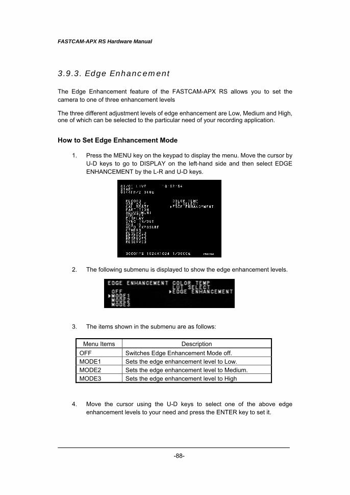
FASTCAM-APX RS Hardware Manual
-88-
3.9.3. Edge Enhancement The Edge Enhancement feature of the FASTCAM-APX RS allows you to set the camera to one of three enhancement levels The three different adjustment levels of edge enhancement are Low, Medium and High, one of which can be selected to the particular need of your recording application. How to Set Edge Enhancement Mode
1. Press the MENU key on the keypad to display the menu. Move the cursor by U-D keys to go to DISPLAY on the left-hand side and then select EDGE ENHANCEMENT by the L-R and U-D keys.
2. The following submenu is displayed to show the edge enhancement levels.
3. The items shown in the submenu are as follows:
Menu Items Description OFF Switches Edge Enhancement Mode off. MODE1 Sets the edge enhancement level to Low. MODE2 Sets the edge enhancement level to Medium. MODE3 Sets the edge enhancement level to High
4. Move the cursor using the U-D keys to select one of the above edge
enhancement levels to your need and press the ENTER key to set it.
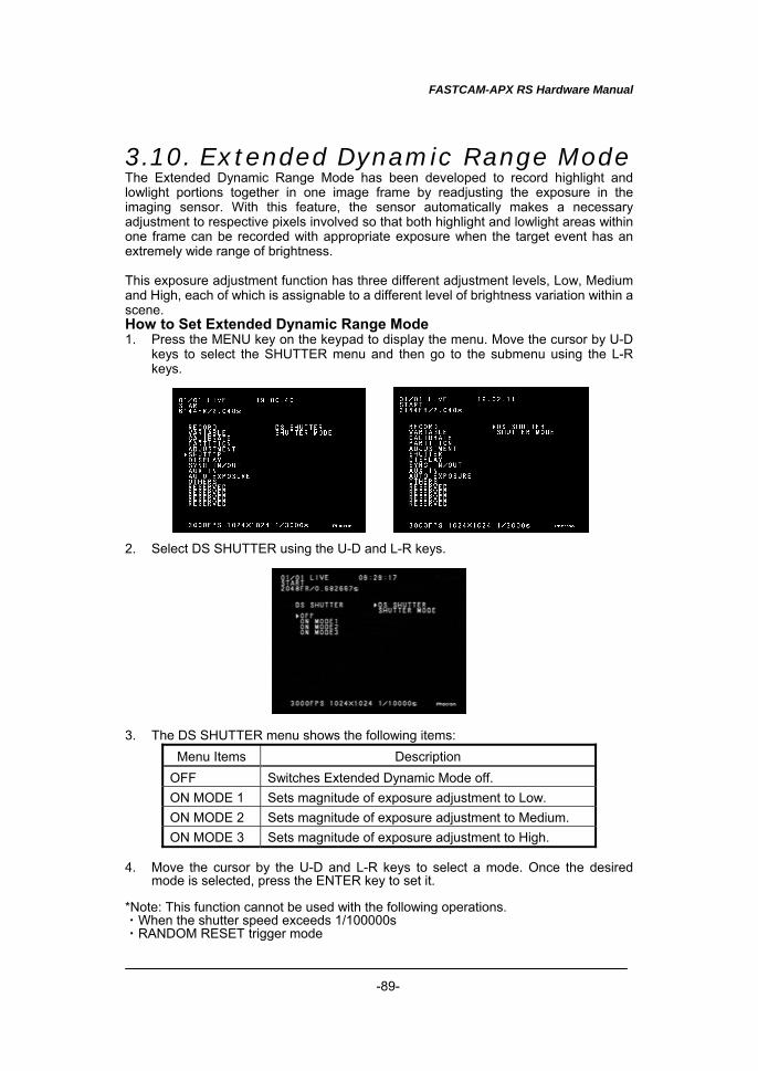
FASTCAM-APX RS Hardware Manual
-89-
3.10. Extended Dynamic Range Mode The Extended Dynamic Range Mode has been developed to record highlight and lowlight portions together in one image frame by readjusting the exposure in the imaging sensor. With this feature, the sensor automatically makes a necessary adjustment to respective pixels involved so that both highlight and lowlight areas within one frame can be recorded with appropriate exposure when the target event has an extremely wide range of brightness. This exposure adjustment function has three different adjustment levels, Low, Medium and High, each of which is assignable to a different level of brightness variation within a scene. How to Set Extended Dynamic Range Mode 1. Press the MENU key on the keypad to display the menu. Move the cursor by U-D
keys to select the SHUTTER menu and then go to the submenu using the L-R keys.
2. Select DS SHUTTER using the U-D and L-R keys. 3. The DS SHUTTER menu shows the following items:
Menu Items Description OFF Switches Extended Dynamic Mode off. ON MODE 1 Sets magnitude of exposure adjustment to Low. ON MODE 2 Sets magnitude of exposure adjustment to Medium. ON MODE 3 Sets magnitude of exposure adjustment to High.
4. Move the cursor by the U-D and L-R keys to select a mode. Once the desired
mode is selected, press the ENTER key to set it. *Note: This function cannot be used with the following operations. ・When the shutter speed exceeds 1/100000s ・RANDOM RESET trigger mode
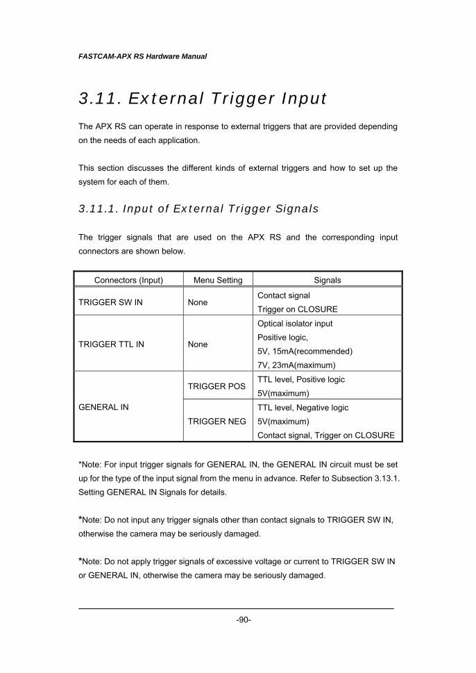
FASTCAM-APX RS Hardware Manual
-90-
3.11. External Trigger Input The APX RS can operate in response to external triggers that are provided depending
on the needs of each application.
This section discusses the different kinds of external triggers and how to set up the
system for each of them.
3.11.1. Input of External Trigger Signals
The trigger signals that are used on the APX RS and the corresponding input
connectors are shown below.
Connectors (Input) Menu Setting Signals
TRIGGER SW IN None Contact signal
Trigger on CLOSURE
TRIGGER TTL IN None
Optical isolator input
Positive logic,
5V, 15mA(recommended)
7V, 23mA(maximum)
TRIGGER POSTTL level, Positive logic
5V(maximum)
GENERAL IN
TRIGGER NEG
TTL level, Negative logic
5V(maximum)
Contact signal, Trigger on CLOSURE
*Note: For input trigger signals for GENERAL IN, the GENERAL IN circuit must be set
up for the type of the input signal from the menu in advance. Refer to Subsection 3.13.1.
Setting GENERAL IN Signals for details.
*Note: Do not input any trigger signals other than contact signals to TRIGGER SW IN,
otherwise the camera may be seriously damaged.
*Note: Do not apply trigger signals of excessive voltage or current to TRIGGER SW IN
or GENERAL IN, otherwise the camera may be seriously damaged.
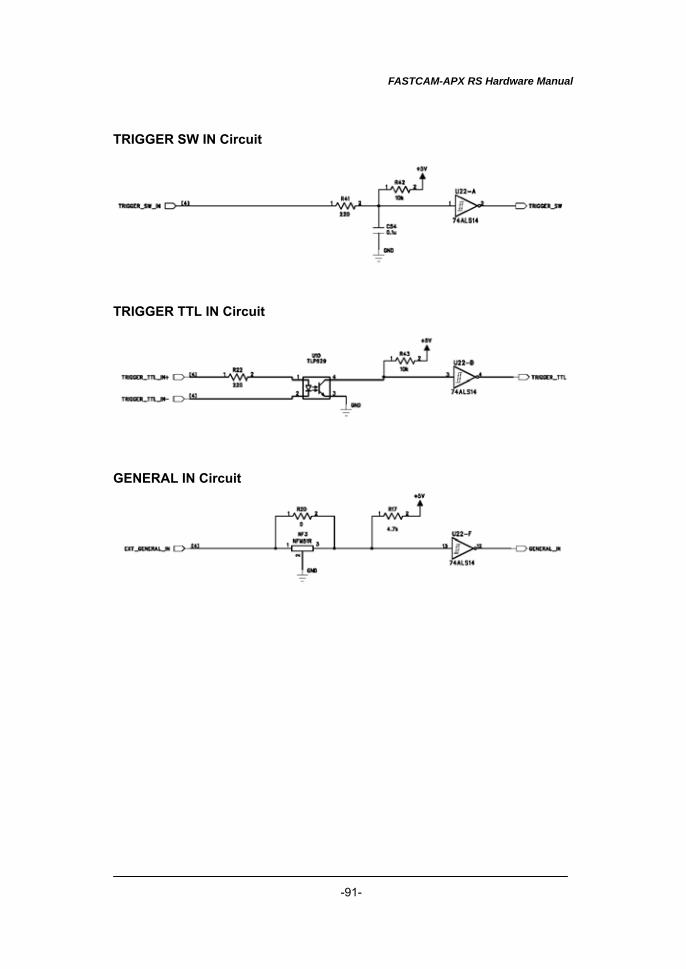
FASTCAM-APX RS Hardware Manual
-91-
TRIGGER SW IN Circuit
TRIGGER TTL IN Circuit
GENERAL IN Circuit
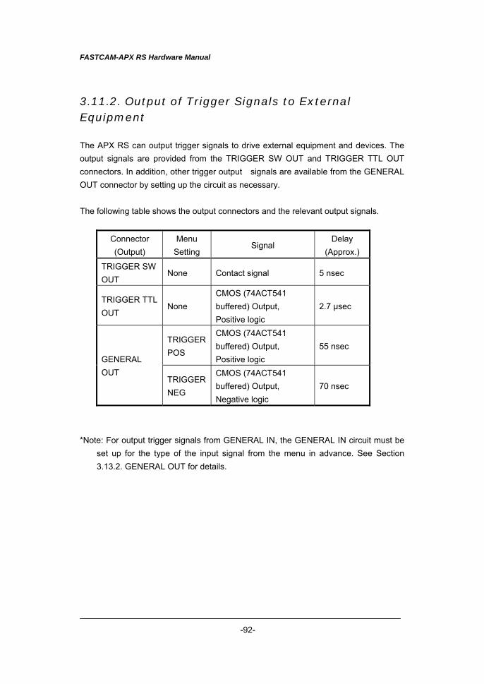
FASTCAM-APX RS Hardware Manual
-92-
3.11.2. Output of Trigger Signals to External Equipment The APX RS can output trigger signals to drive external equipment and devices. The output signals are provided from the TRIGGER SW OUT and TRIGGER TTL OUT connectors. In addition, other trigger output signals are available from the GENERAL OUT connector by setting up the circuit as necessary. The following table shows the output connectors and the relevant output signals.
Connector (Output)
Menu Setting
Signal Delay
(Approx.)
TRIGGER SW OUT
None Contact signal 5 nsec
TRIGGER TTL OUT
None CMOS (74ACT541 buffered) Output, Positive logic
2.7 µsec
TRIGGER POS
CMOS (74ACT541 buffered) Output, Positive logic
55 nsec GENERAL OUT
TRIGGER NEG
CMOS (74ACT541 buffered) Output, Negative logic
70 nsec
*Note: For output trigger signals from GENERAL IN, the GENERAL IN circuit must be
set up for the type of the input signal from the menu in advance. See Section 3.13.2. GENERAL OUT for details.
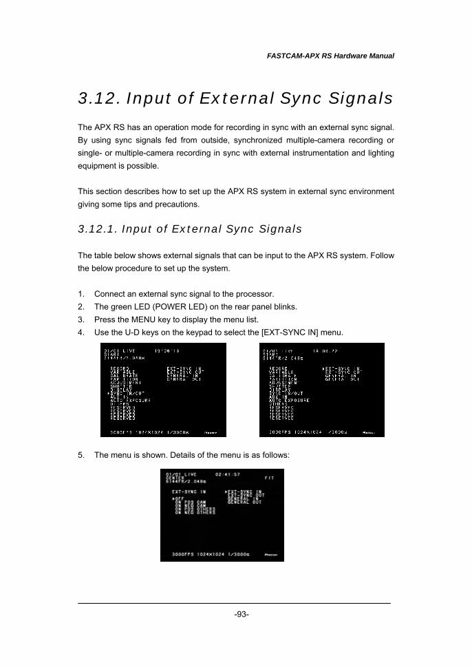
FASTCAM-APX RS Hardware Manual
-93-
3.12. Input of External Sync Signals The APX RS has an operation mode for recording in sync with an external sync signal. By using sync signals fed from outside, synchronized multiple-camera recording or single- or multiple-camera recording in sync with external instrumentation and lighting equipment is possible. This section describes how to set up the APX RS system in external sync environment giving some tips and precautions. 3.12.1. Input of External Sync Signals The table below shows external signals that can be input to the APX RS system. Follow the below procedure to set up the system. 1. Connect an external sync signal to the processor. 2. The green LED (POWER LED) on the rear panel blinks. 3. Press the MENU key to display the menu list. 4. Use the U-D keys on the keypad to select the [EXT-SYNC IN] menu. 5. The menu is shown. Details of the menu is as follows:
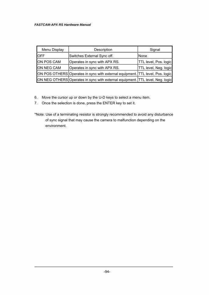
FASTCAM-APX RS Hardware Manual
-94-
Menu Display Description Signal
OFF Switches External Sync off. None ON POS CAM Operates in sync with APX RS. TTL level, Pos. logic ON NEG CAM Operates in sync with APX RS. TTL level, Neg. logic ON POS OTHERS Operates in sync with external equipment. TTL level, Pos. logic ON NEG OTHERS Operates in sync with external equipment. TTL level, Neg. logic
6. Move the cursor up or down by the U-D keys to select a menu item. 7. Once the selection is done, press the ENTER key to set it. *Note: Use of a terminating resistor is strongly recommended to avoid any disturbance
of sync signal that may cause the camera to malfunction depending on the environment.
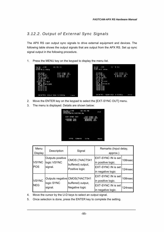
FASTCAM-APX RS Hardware Manual
-95-
3.12.2. Output of External Sync Signals The APX RS can output sync signals to drive external equipment and devices. The following table shows the output signals that are output from the APX RS. Set up sync signal output in the following procedure. 1. Press the MENU key on the keypad to display the menu list. 2. Move the ENTER key on the keypad to select the [EXT-SYNC OUT] menu. 3. The menu is displayed. Details are shown below:
Menu Display
Description Signal Remarks (Input delay,
approx.)
EXT-SYNC IN is set in positive logic.
108nsec VSYNC POS
Outputs positive logic VSYNC signal.
CMOS (74ACT541 buffered) output, Positive logic EXT-SYNC IN is set
in negative logic 124nsec
EXT-SYNC IN is set in positive logic.
108nsec VSYNC NEG
Outputs negative logic SYNC signal.
CMOS(74ACT541 buffered) output, Negative logic
EXT-SYNC IN is set in negative logic.
124nsec
4. Move the cursor by the U-D keys to select an output signal. 5. Once selection is done, press the ENTER key to complete the setting.
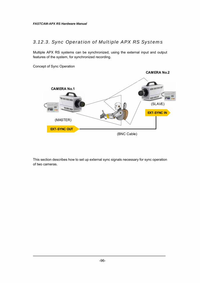
FASTCAM-APX RS Hardware Manual
-96-
EXT-SYNC OUT
EXT-SYNC IN
(MASTER)
(SLAVE)
CAMERA No.1
CAMERA No.2
(BNC Cable)
3.12.3. Sync Operation of Multiple APX RS Systems Multiple APX RS systems can be synchronized, using the external input and output features of the system, for synchronized recording. Concept of Sync Operation This section describes how to set up external sync signals necessary for sync operation of two cameras.
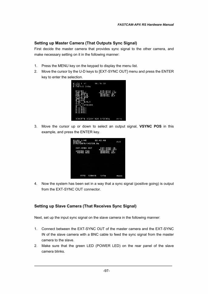
FASTCAM-APX RS Hardware Manual
-97-
Setting up Master Camera (That Outputs Sync Signal) First decide the master camera that provides sync signal to the other camera, and make necessary setting on it in the following manner: 1. Press the MENU key on the keypad to display the menu list. 2. Move the cursor by the U-D keys to [EXT-SYNC OUT] menu and press the ENTER
key to enter the selection. 3. Move the cursor up or down to select an output signal, VSYNC POS in this
example, and press the ENTER key. 4. Now the system has been set in a way that a sync signal (positive going) is output
from the EXT-SYNC OUT connector. Setting up Slave Camera (That Receives Sync Signal) Next, set up the input sync signal on the slave camera in the following manner: 1. Connect between the EXT-SYNC OUT of the master camera and the EXT-SYNC
IN of the slave camera with a BNC cable to feed the sync signal from the master camera to the slave.
2. Make sure that the green LED (POWER LED) on the rear panel of the slave camera blinks.
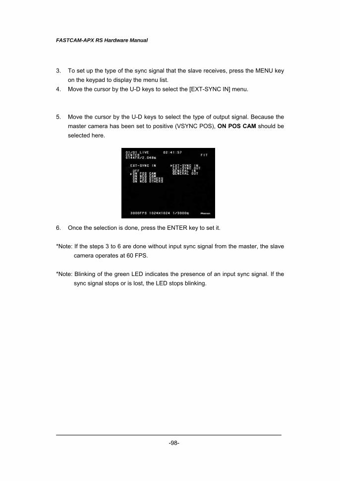
FASTCAM-APX RS Hardware Manual
-98-
3. To set up the type of the sync signal that the slave receives, press the MENU key on the keypad to display the menu list.
4. Move the cursor by the U-D keys to select the [EXT-SYNC IN] menu. 5. Move the cursor by the U-D keys to select the type of output signal. Because the
master camera has been set to positive (VSYNC POS), ON POS CAM should be selected here.
6. Once the selection is done, press the ENTER key to set it. *Note: If the steps 3 to 6 are done without input sync signal from the master, the slave
camera operates at 60 FPS. *Note: Blinking of the green LED indicates the presence of an input sync signal. If the
sync signal stops or is lost, the LED stops blinking.
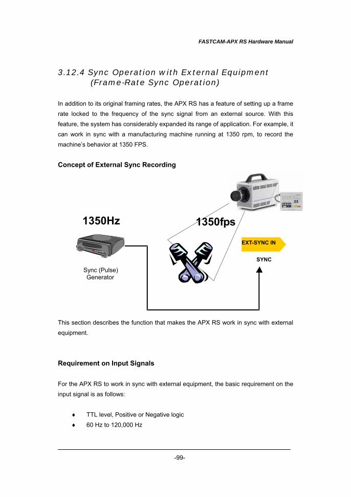
FASTCAM-APX RS Hardware Manual
-99-
3.12.4 Sync Operation with External Equipment (Frame-Rate Sync Operation)
In addition to its original framing rates, the APX RS has a feature of setting up a frame
rate locked to the frequency of the sync signal from an external source. With this
feature, the system has considerably expanded its range of application. For example, it
can work in sync with a manufacturing machine running at 1350 rpm, to record the
machine’s behavior at 1350 FPS.
Concept of External Sync Recording This section describes the function that makes the APX RS work in sync with external
equipment.
Requirement on Input Signals
For the APX RS to work in sync with external equipment, the basic requirement on the
input signal is as follows:
♦ TTL level, Positive or Negative logic
♦ 60 Hz to 120,000 Hz
SYNC
SLAVE
1350Hz
Sync (Pulse) Generator
1350fps
EXT-SYNC IN
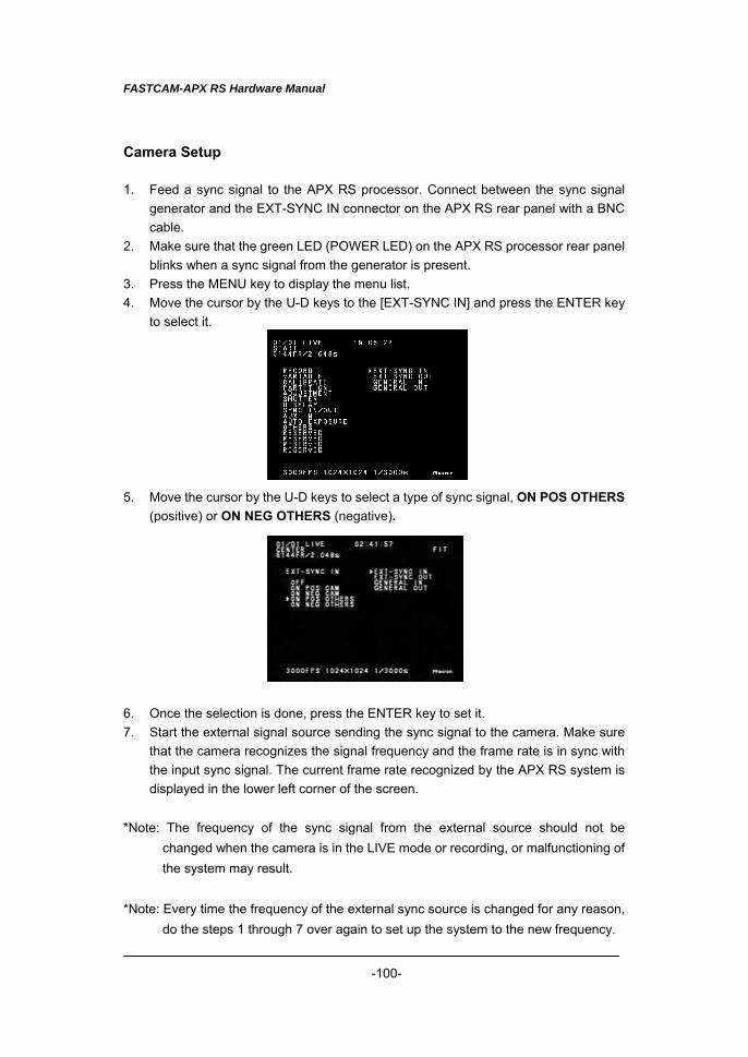
FASTCAM-APX RS Hardware Manual
-100-
Camera Setup 1. Feed a sync signal to the APX RS processor. Connect between the sync signal
generator and the EXT-SYNC IN connector on the APX RS rear panel with a BNC cable.
2. Make sure that the green LED (POWER LED) on the APX RS processor rear panel blinks when a sync signal from the generator is present.
3. Press the MENU key to display the menu list. 4. Move the cursor by the U-D keys to the [EXT-SYNC IN] and press the ENTER key
to select it. 5. Move the cursor by the U-D keys to select a type of sync signal, ON POS OTHERS
(positive) or ON NEG OTHERS (negative). 6. Once the selection is done, press the ENTER key to set it. 7. Start the external signal source sending the sync signal to the camera. Make sure
that the camera recognizes the signal frequency and the frame rate is in sync with the input sync signal. The current frame rate recognized by the APX RS system is displayed in the lower left corner of the screen.
*Note: The frequency of the sync signal from the external source should not be
changed when the camera is in the LIVE mode or recording, or malfunctioning of the system may result.
*Note: Every time the frequency of the external sync source is changed for any reason,
do the steps 1 through 7 over again to set up the system to the new frequency.
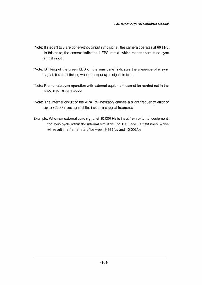
FASTCAM-APX RS Hardware Manual
-101-
*Note: If steps 3 to 7 are done without input sync signal, the camera operates at 60 FPS.
In this case, the camera indicates 1 FPS in text, which means there is no sync signal input.
*Note: Blinking of the green LED on the rear panel indicates the presence of a sync
signal. It stops blinking when the input sync signal is lost. *Note: Frame-rate sync operation with external equipment cannot be carried out in the
RANDOM RESET mode. *Note: The internal circuit of the APX RS inevitably causes a slight frequency error of
up to ±22.83 nsec against the input sync signal frequency. Example: When an external sync signal of 10,000 Hz is input from external equipment,
the sync cycle within the internal circuit will be 100 usec ± 22.83 nsec, which will result in a frame rate of between 9,998fps and 10,002fps
FASTCAM-APX RS Hardware Manual
-102-
3.12.5. Sync Operation of APX RS and Other Models of Cameras
(Sync Operation of Mixed Models of Cameras) Using the APX RS camera’s feature of setting up a frame rate locked to the frequency of a sync signal from an external source described in the previous Section 3.11.4., the model allows for sync operation with other models of FASTCAM cameras, such as the Ultima 512 and 1024R2 models. Synchronizing the APX RS to FASTCAM APX or Ultima-512 To make the APX RS camera synchronized to the APX or the 512, the APX or the 512 should be the master camera and the APX RS slave. Setting up the APX or 512 (Master Camera That Feeds Sync Signal to the slave APX RS) The APX and Ultima-512 have rear panel connectors of the same specifications as the APX RS. Also, their control software GUI and remote keypad menu are of the same specifications as the APX RS. Because of these common specifications, setting up the APX or 512 camera is carried out as if both the master and slave cameras are of one same model, the APX, the 512 or the APX RS. 1. Press the MENU key on the keypad to display the menu list. 2. Move the cursor by the U-D keys to [EXT-SYNC OUT] menu and press the ENTER
key to enter the selection. 3. Move the cursor up or down to select an output signal, VSYNC POS in this
example, and press the ENTER key. 4. Now the system has been set in the way that a sync signal (positive going) is
output from the EXT-SYNC OUT connector. Setting up the APX RS (Slave Camera That Receives Sync Signal from the Master) Next, set up the input sync signal on the slave camera. 1. Connect between the EXT-SYNC OUT of the master camera and the EXT-SYNC
IN of the slave camera with a BNC cable to feed the sync signal from the master camera to the slave.
2. Make sure that the green LED (POWER LED) on the rear panel of the slave camera blinks.
3. To set up the type of sync signal that the slave receives, press the MENU key on the keypad to display the menu list.
4. Move the cursor by the U-D keys to select the [EXT-SYNC IN] menu.
FASTCAM-APX RS Hardware Manual
-103-
5. Move the cursor by the U-D keys to select the type of output signal. Because the master camera has been set to positive (VSYNC POS), ON POS CAM should be selected here.
6. Once the selection is done, press the ENTER key to set it. *Note: When you wish to make the APX or 512 camera synchronized to the APX RS,
the APX RS is the master camera and the APX or 512 the slave. Follow the above procedure swapping the places of the two cameras.
Synchronizing the APX RS to FASTCAM-Ultima 1024R2 To make the APX RS camera synchronized to an Ultima 1024R2, the 1024R2 is the master camera and the APX RS slave. Setting up the 1024R2 (Master Camera Feeding Sync Signal to the Slave) 1. Press the MENU key on the keypad to display the menu list. 2. Move the cursor by the U-D keys to [EXT OUT] menu and press the ENTER key to
set the selection. 3. Move the cursor up or down to select an output signal from the EXT OUT
connector. Select [VSYNC POS] in this example, and press the ENTER key. 4. Now the system has been set in the way that a sync signal (positive going) is
output from EXT OUT connector. Setting up the APX RS (Slave Camera Receiving Sync Signal from the Master) Next, set up the input sync signal on the slave camera. 1. Connect between the EXT OUT of the master camera and the EXT-SYNC IN of the
slave camera with a BNC cable to feed the sync signal from the master camera to the slave.
2. Make sure that the green LED (POWER LED) on the rear panel of the slave camera blinks.
3. To set up the type of sync signal that the slave receives, press the MENU key on the keypad to display the menu list.
4. Move the cursor by the U-D keys to select the [EXT-SYNC IN] menu. 5. Move the cursor by the U-D keys to select the type of output signal. Because the
master camera has been set to positive (VSYNC POS), ON POS CAM should be selected here.
6. Once the selection is done, press the ENTER key to set it. *Note: It is not possible to make the 1024R2 synchronized to the APX RS because the
1024R2 does not have the function to follow a sync signal from external source (frame-rate sync recording feature).
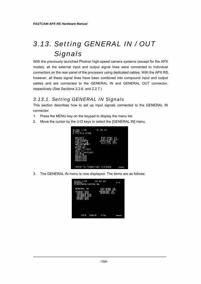
FASTCAM-APX RS Hardware Manual
-104-
3.13. Setting GENERAL IN / OUT Signals
With the previously launched Photron high-speed camera systems (except for the APX model), all the external input and output signal lines were connected to individual connectors on the rear panel of the processor using dedicated cables. With the APX RS, however, all these signal lines have been combined into compound input and output cables and are connected to the GENERAL IN and GENERAL OUT connector, respectively (See Sections 2.2.6. and 2.2.7.) 3.13.1. Setting GENERAL IN Signals This section describes how to set up input signals connected to the GENERAL IN connector. 1. Press the MENU key on the keypad to display the menu list. 2. Move the cursor by the U-D keys to select the [GENERAL IN] menu. 3. The GENERAL IN menu is now displayed. The items are as follows:
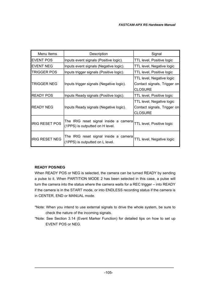
FASTCAM-APX RS Hardware Manual
-105-
Menu Items Description Signal
EVENT POS Inputs event signals (Positive logic). TTL level, Positive logic EVENT NEG Inputs event signals (Negative logic). TTL level, Negative logic TRIGGER POS Inputs trigger signals (Positive logic). TTL level, Positive logic
TRIGGER NEG Inputs trigger signals (Negative logic). TTL level, Negative logic Contact signals, Trigger on CLOSURE
READY POS Inputs Ready signals (Positive logic). TTL level, Positive logic
READY NEG Inputs Ready signals (Negative logic). TTL level, Negative logic Contact signals, Trigger on CLOSURE
IRIG RESET POSThe IRIG reset signal inside a camera (1PPS) is outputted on H level. TTL level, Positive logic
IRIG RESET NEGThe IRIG reset signal inside a camera (1PPS) is outputted on L level.
TTL level, Negative logic
READY POS/NEG When READY POS or NEG is selected, the camera can be turned READY by sending a pulse to it. When PARTITION MODE 2 has been selected in this case, a pulse will turn the camera into the status where the camera waits for a REC trigger – into READY if the camera is in the START mode, or into ENDLESS recording status if the camera is in CENTER, END or MANUAL mode. *Note: When you intend to use external signals to drive the whole system, be sure to
check the nature of the incoming signals. *Note: See Section 3.14 (Event Marker Function) for detailed tips on how to set up
EVENT POS or NEG.
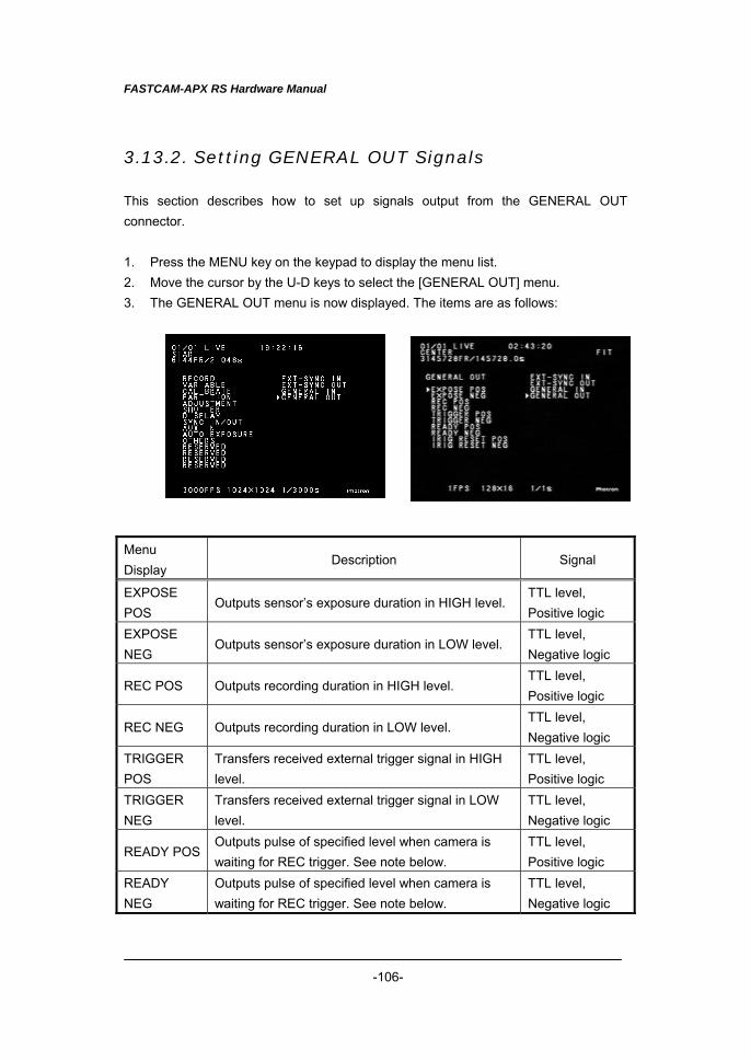
FASTCAM-APX RS Hardware Manual
-106-
3.13.2. Setting GENERAL OUT Signals This section describes how to set up signals output from the GENERAL OUT connector. 1. Press the MENU key on the keypad to display the menu list. 2. Move the cursor by the U-D keys to select the [GENERAL OUT] menu. 3. The GENERAL OUT menu is now displayed. The items are as follows:
Menu Display
Description Signal
EXPOSE POS
Outputs sensor’s exposure duration in HIGH level. TTL level, Positive logic
EXPOSE NEG
Outputs sensor’s exposure duration in LOW level. TTL level, Negative logic
REC POS Outputs recording duration in HIGH level. TTL level, Positive logic
REC NEG Outputs recording duration in LOW level. TTL level, Negative logic
TRIGGER POS
Transfers received external trigger signal in HIGH level.
TTL level, Positive logic
TRIGGER NEG
Transfers received external trigger signal in LOW level.
TTL level, Negative logic
READY POSOutputs pulse of specified level when camera is waiting for REC trigger. See note below.
TTL level, Positive logic
READY NEG
Outputs pulse of specified level when camera is waiting for REC trigger. See note below.
TTL level, Negative logic

FASTCAM-APX RS Hardware Manual
-107-
READY POS/NEG When READY POS or READY NEG has been selected, a pulse of the specified level is output if the camera is waiting for a REC trigger – a trigger that will turn the camera into READY if it is in the START mode, and ENDLESS in the CENTER, END or MANUAL mode. This feature is valid only in the START, CENTER, END or MANUAL mode. *Note: When you intend to use these signals to drive the whole system, be sure to
check the nature of the outgoing signals.
FASTCAM-APX RS Hardware Manual
-108-
3.14. Event Marker Function The APX RS’s Event Marker function makes it possible to record a frame number, on
the fly, at each external marking signal so that you can jump to the marked frame (event
frame) when playing recorded images. In addition to triggering points, these event
marks given at any moments of interesting event will let you play back such interesting
events quickly. Up to ten event frames can be marked in each partitioned section.
Marking is done at an edge of the incoming marker pulse. The immediately subsequent
frame after receipt of a marker pulse is recorded as an event frame. The following
describes how to place event marks:
1. Press the MENU key on the keypad to display the menu list. Move the cursor by
the U-D keys to select the GENERAL IN menu. Using the cursor in the GENERAL
IN menu, select [EVENT POS] or [EVENT NEG]. EVENT POS marks an event at
the rising edge of the marking signal and EVENT NEG at the falling edge.
2. Send pulses into the GENERAL IN connector each moment you see an interesting
event during a recording session.
3. Up to ten marking pulses are accepted in a session.
4. Recording comes to an end.
5. Press the LIVE/MEMORY key to switch to the MEMORY mode.
6. Press the △ or ▽ FRAME RATE key to jump to the first marked event. At each
press on either key, playback jumps to previous or subsequent event frames.
7. While an event frame is displayed on the screen, the text shows [EVENT FRAME
x] where the x is a number between 1 and 10 each representing the serial number
of an event frame. *Note: This function is not available with the DUAL FRAME RATE mode.
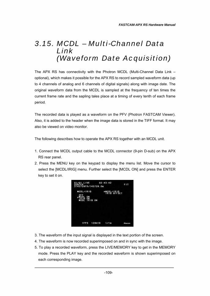
FASTCAM-APX RS Hardware Manual
-109-
3.15. MCDL – Multi-Channel Data Link (Waveform Date Acquisition)
The APX RS has connectivity with the Photron MCDL (Multi-Channel Data Link –
optional), which makes it possible for the APX RS to record sampled waveform data (up
to 4 channels of analog and 6 channels of digital signals) along with image date. The
original waveform data from the MCDL is sampled at the frequency of ten times the
current frame rate and the sapling tales place at a timing of every tenth of each frame
period.
The recorded data is played as a waveform on the PFV (Photron FASTCAM Viewer).
Also, it is added to the header when the image data is stored in the TIFF format. It may
also be viewed on video monitor.
The following describes how to operate the APX RS together with an MCDL unit.
1. Connect the MCDL output cable to the MCDL connector (9-pin D-sub) on the APX
RS rear panel.
2. Press the MENU key on the keypad to display the menu list. Move the cursor to
select the [MCDL/IRIG] menu. Further select the [MCDL ON] and press the ENTER
key to set it on. 3. The waveform of the input signal is displayed in the text portion of the screen.
4. The waveform is now recorded superimposed on and in sync with the image.
5. To play a recorded waveform, press the LIVE/MEMORY key to get in the MEMORY
mode. Press the PLAY key and the recorded waveform is shown superimposed on
each corresponding image.
FASTCAM-APX RS Hardware Manual
-110-
*Note: This feature cannot be used at 128 x 16 resolution.
*Note: When you use both MCDL and IRIG together, select [MCDL IRIG ON] on the
menu.
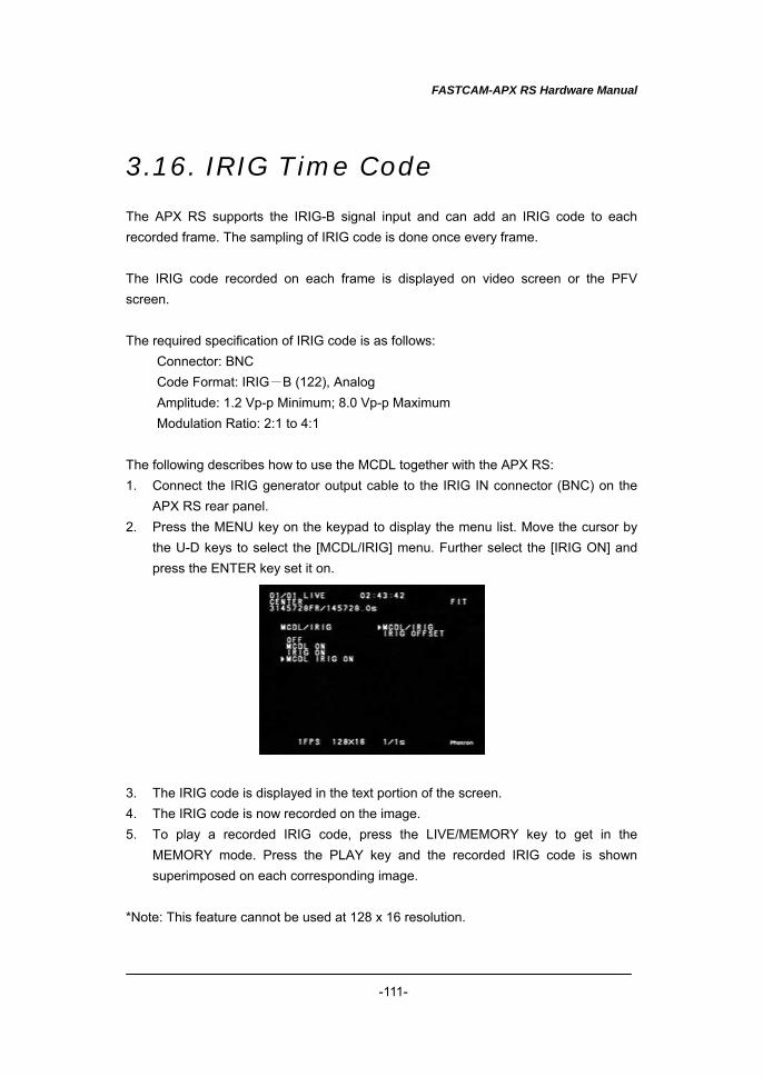
FASTCAM-APX RS Hardware Manual
-111-
3.16. IRIG Time Code The APX RS supports the IRIG-B signal input and can add an IRIG code to each recorded frame. The sampling of IRIG code is done once every frame. The IRIG code recorded on each frame is displayed on video screen or the PFV screen. The required specification of IRIG code is as follows:
Connector: BNC Code Format: IRIG-B (122), Analog Amplitude: 1.2 Vp-p Minimum; 8.0 Vp-p Maximum Modulation Ratio: 2:1 to 4:1
The following describes how to use the MCDL together with the APX RS: 1. Connect the IRIG generator output cable to the IRIG IN connector (BNC) on the
APX RS rear panel. 2. Press the MENU key on the keypad to display the menu list. Move the cursor by
the U-D keys to select the [MCDL/IRIG] menu. Further select the [IRIG ON] and press the ENTER key set it on.
3. The IRIG code is displayed in the text portion of the screen. 4. The IRIG code is now recorded on the image. 5. To play a recorded IRIG code, press the LIVE/MEMORY key to get in the
MEMORY mode. Press the PLAY key and the recorded IRIG code is shown superimposed on each corresponding image.
*Note: This feature cannot be used at 128 x 16 resolution.
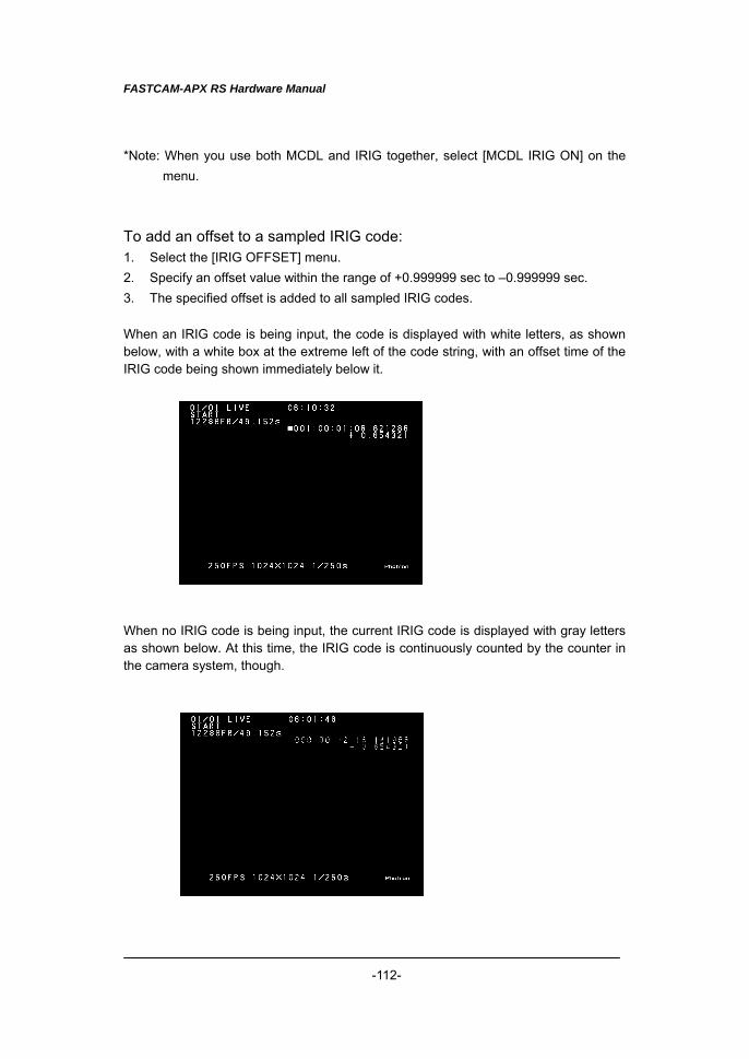
FASTCAM-APX RS Hardware Manual
-112-
*Note: When you use both MCDL and IRIG together, select [MCDL IRIG ON] on the menu.
To add an offset to a sampled IRIG code: 1. Select the [IRIG OFFSET] menu. 2. Specify an offset value within the range of +0.999999 sec to –0.999999 sec. 3. The specified offset is added to all sampled IRIG codes. When an IRIG code is being input, the code is displayed with white letters, as shown below, with a white box at the extreme left of the code string, with an offset time of the IRIG code being shown immediately below it. When no IRIG code is being input, the current IRIG code is displayed with gray letters as shown below. At this time, the IRIG code is continuously counted by the counter in the camera system, though.
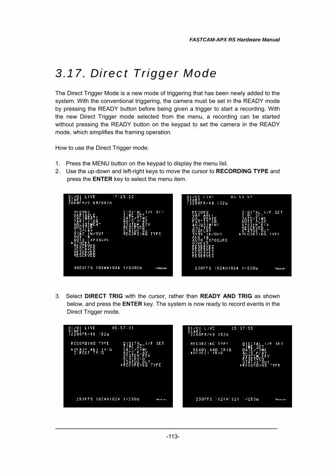
FASTCAM-APX RS Hardware Manual
-113-
3.17. Direct Trigger Mode The Direct Trigger Mode is a new mode of triggering that has been newly added to the system. With the conventional triggering, the camera must be set in the READY mode by pressing the READY button before being given a trigger to start a recording. With the new Direct Trigger mode selected from the menu, a recording can be started without pressing the READY button on the keypad to set the camera in the READY mode, which simplifies the framing operation. How to use the Direct Trigger mode: 1. Press the MENU button on the keypad to display the menu list. 2. Use the up-down and left-right keys to move the cursor to RECORDING TYPE and
press the ENTER key to select the menu item. 3. Select DIRECT TRIG with the cursor, rather than READY AND TRIG as shown
below, and press the ENTER key. The system is now ready to record events in the Direct Trigger mode.
FASTCAM-APX RS Hardware Manual
-114-
Operation of the camera in each triggering mode: READY AND TRIG mode (default setting) When the camera is set in this triggering mode (default setting), the READY key must always be pressed before pressing the REC key to start a recording. DIRECT TRIG mode (optional setting) With this triggering mode selected, a recording can be started with presses on the REC key only, without pressing the READY key to set the camera in the READY mode. Note this mode is optional and should be selected in the above-describe procedure to use it. When DIRECT TRIG mode is selected, the camera operation sequence for each triggering mode is as follows: Note: [ ] denotes the camera behavior while “trigger” means a trigger entry by pressing the REC button on the keypad. ・For START, RANDOM, RANDOM_RESET or TWO_STAGES mode of recording:
Sequence: [LIVE] → “trigger” → [READY] → “trigger” → [REC] ・For CENTER, END, MANUAL, RANDOM_CENTER or RANDOM_ MANUAL mode of operation:
Sequence: [LIVE] → “trigger” → [ENDLESS] → “trigger” → [REC]
FASTCAM-APX RS Hardware Manual
-115-
Chapter 4 Playback
4.1. Playing Recorded Images 4.2. Search Images of Interest
(Fast Forward/Rewind Play) 4.3. Slow Playback (Jog) 4.4. Zooming (Zoom / Fit / Scroll) 4.5. Block Playback (Playback of Clips of Interest) 4.6. Text Display – Hide / Unhide 4.7. Displaying Crosshair Cursor 4.8. Display R / G / B Planes (Color Model Only) 4.9. Switching NTSC / PAL Video Output 4.10. Automatic Playback 4.11. Playback Event Markers
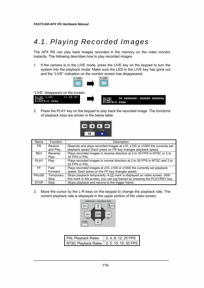
FASTCAM-APX RS Hardware Manual
-116-
4.1. Playing Recorded Images The APX RS can play back images recorded in the memory on the video monitor instantly. The following describes how to play recorded images. 1. If the camera is in the LIVE mode, press the LIVE key on the keypad to turn the
system into the playback mode. Make sure the LED in the LIVE key has gone out and the “LIVE” indication on the monitor screen has disappeared.
“LIVE” disappears on the screen. 2. Press the PLAY key on the keypad to play back the recorded image. The functions
of playback keys are shown in the below table.
Name Function Description
FR Rewind and Play
Rewinds and plays recorded images at x10, x100 or x1000 the currently set playback speed. Each press on FR key changes playback speed.
REV Reverse Play
Plays recorded images in reverse direction at 2 to 30 FPS in NTSC or 2 to 25 FPS in PAL
PLAY Play Plays recorded images in normal direction at 2 to 30 FPS in NTSC and 2 to 25 FPS in PAL.
FF Fast Forward
Plays recorded images at x10, x100 or x1000 the currently set playback speed. Each press on the FF key changes speed.
PAUSE Temporary Stop
Stops playback temporarily. A [||] mark is displayed on video screen. With this mark in the screen, you can jog frames by pressing the PLAY/REV key.
STOP Stop Stops playback and returns to the trigger frame. 3. Move the cursor by the L-R keys on the keypad to change the playback rate. The
current playback rate is displayed in the upper portion of the video screen.
PAL Playback Rates 2; 4; 8; 12; 25 FPS NTSC Playback Rates 2; 5; 10; 15; 30 FPS
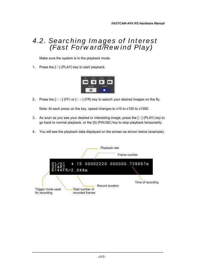
FASTCAM-APX RS Hardware Manual
-117-
4.2. Searching Images of Interest (Fast Forward/Rewind Play)
Make sure the system is in the playback mode.
1. Press the [>] (PLAY) key to start playback. 2. Press the [>>] (FF) or [<<] (FR) key to search your desired images on the fly.
Note: At each press on the key, speed changes to x10 to x100 to x1000. 3. As soon as you see your desired or interesting image, press the [>] (PLAY) key to
go back to normal playback, or the [II] (PAUSE) key to stop playback temporarily. 4. You will see the playback data displayed on the screen as shown below (example).
Record duration Total number of recorded frames
Playback rate
Trigger mode usedfor recording
Frame number
Time of recording
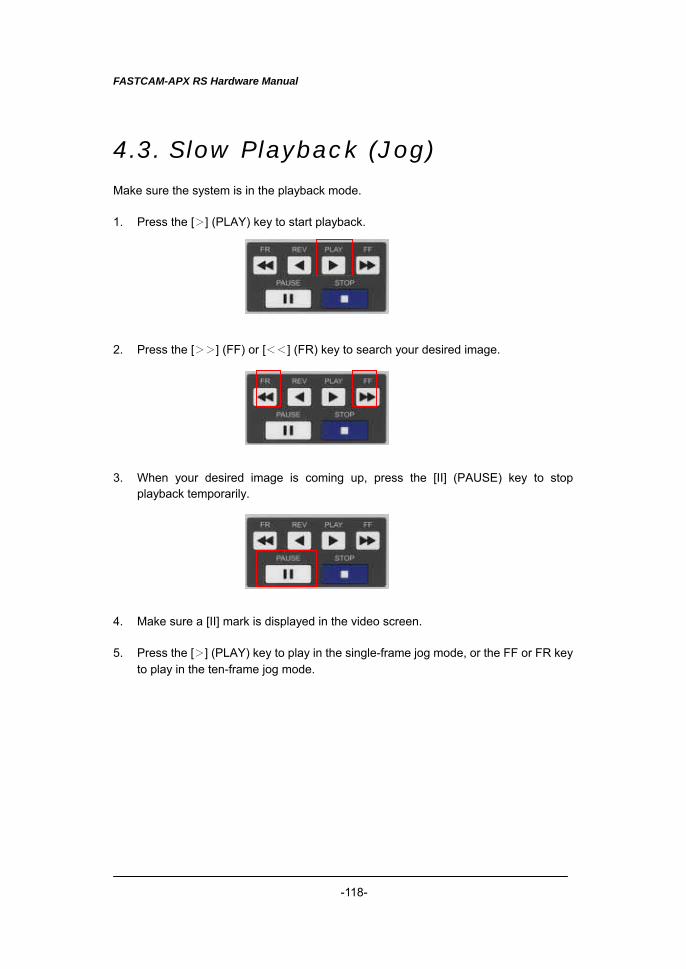
FASTCAM-APX RS Hardware Manual
-118-
4.3. Slow Playback (Jog) Make sure the system is in the playback mode. 1. Press the [>] (PLAY) key to start playback. 2. Press the [>>] (FF) or [<<] (FR) key to search your desired image. 3. When your desired image is coming up, press the [II] (PAUSE) key to stop
playback temporarily.
4. Make sure a [II] mark is displayed in the video screen. 5. Press the [>] (PLAY) key to play in the single-frame jog mode, or the FF or FR key
to play in the ten-frame jog mode.
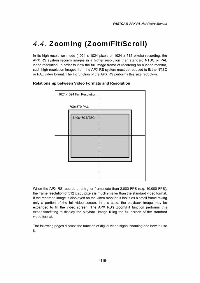
FASTCAM-APX RS Hardware Manual
-119-
4.4. Zooming (Zoom/Fit/Scroll) In its high-resolution mode (1024 x 1024 pixels or 1024 x 512 pixels) recording, the APX RS system records images in a higher resolution than standard NTSC or PAL video resolution. In order to view the full image frame of recording on a video monitor, such high-resolution images from the APX RS system must be reduced to fit the NTSC or PAL video format. The Fit function of the APX RS performs this size reduction. Relationship between Video Formats and Resolution
1024x1024 Full Resolution
700x570 PAL
640x480 NTSC
When the APX RS records at a higher frame rate than 2,000 FPS (e.g. 10,000 FPS), the frame resolution of 512 x 256 pixels is much smaller than the standard video format. If the recorded image is displayed on the video monitor, it looks as a small frame taking only a portion of the full video screen. In this case, the playback image may be expanded to fill the video screen. The APX RS’s Zoom/Fit function performs this expansion/fitting to display the playback image filling the full screen of the standard video format. The following pages discuss the function of digital video signal zooming and how to use it.
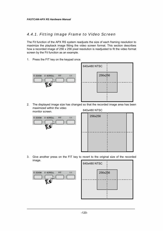
FASTCAM-APX RS Hardware Manual
-120-
4.4.1. Fitting Image Frame to Video Screen The Fit function of the APX RS system readjusts the size of each framing resolution to maximize the playback image fitting the video screen format. This section describes how a recorded image of 256 x 256 pixel resolution is readjusted to fit the video format screen by the Fit function as an example. 1. Press the FIT key on the keypad once.
2. The displayed image size has changed so that the recorded image area has been
maximized within the video monitor screen.
3. Give another press on the FIT key to revert to the original size of the recorded
image.
640x480 NTSC
256x256
640x480 NTSC
256x256
640x480 NTSC
256x256
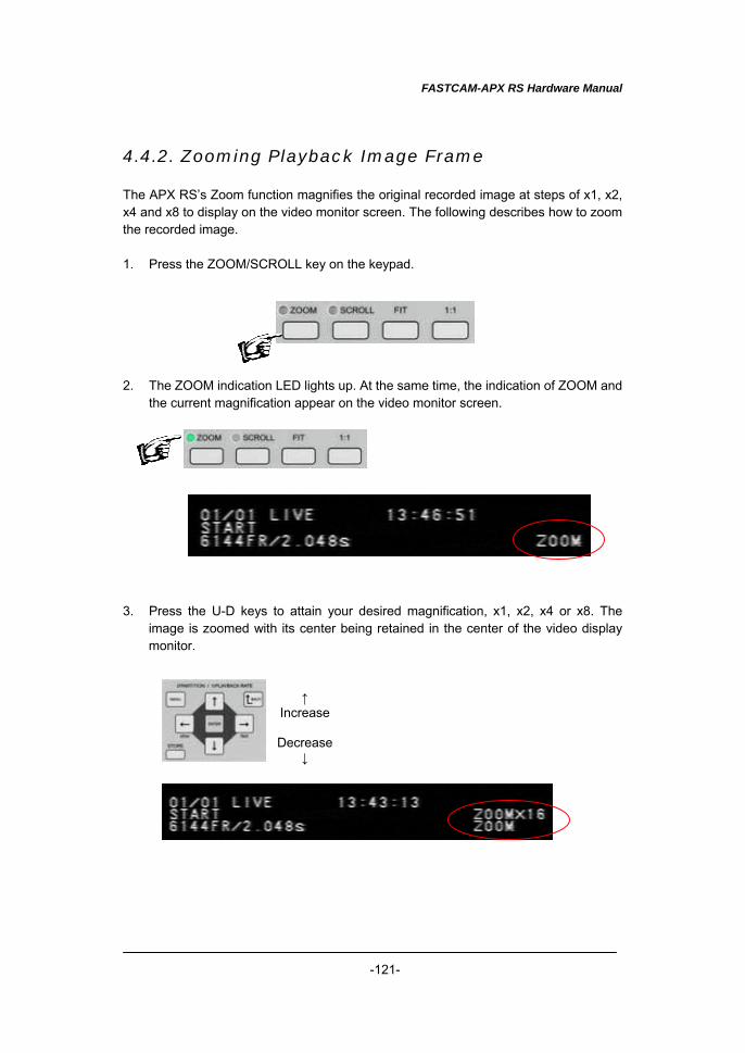
FASTCAM-APX RS Hardware Manual
-121-
4.4.2. Zooming Playback Image Frame The APX RS’s Zoom function magnifies the original recorded image at steps of x1, x2, x4 and x8 to display on the video monitor screen. The following describes how to zoom the recorded image. 1. Press the ZOOM/SCROLL key on the keypad. 2. The ZOOM indication LED lights up. At the same time, the indication of ZOOM and
the current magnification appear on the video monitor screen. 3. Press the U-D keys to attain your desired magnification, x1, x2, x4 or x8. The
image is zoomed with its center being retained in the center of the video display monitor.
↑ Increase
Decrease
↓
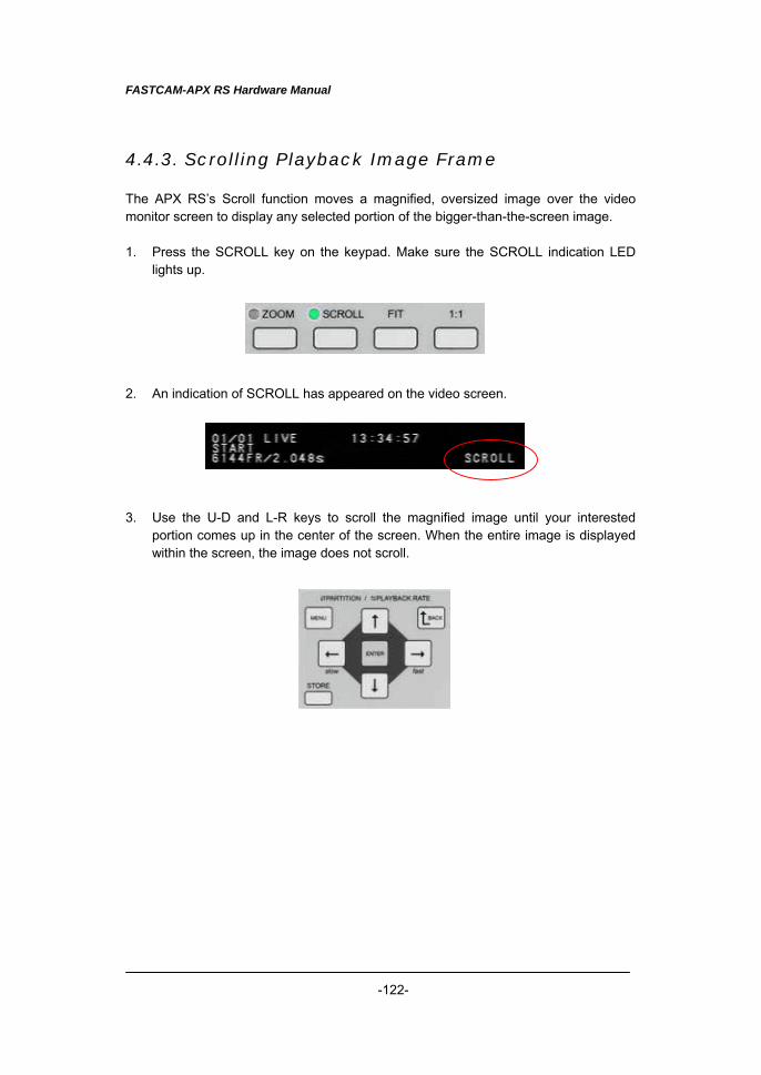
FASTCAM-APX RS Hardware Manual
-122-
4.4.3. Scrolling Playback Image Frame The APX RS’s Scroll function moves a magnified, oversized image over the video monitor screen to display any selected portion of the bigger-than-the-screen image. 1. Press the SCROLL key on the keypad. Make sure the SCROLL indication LED
lights up. 2. An indication of SCROLL has appeared on the video screen. 3. Use the U-D and L-R keys to scroll the magnified image until your interested
portion comes up in the center of the screen. When the entire image is displayed within the screen, the image does not scroll.
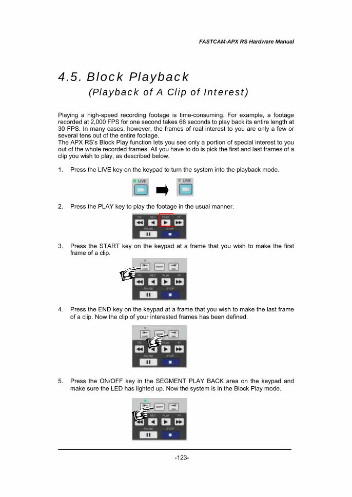
FASTCAM-APX RS Hardware Manual
-123-
4.5. Block Playback (Playback of A Clip of Interest)
Playing a high-speed recording footage is time-consuming. For example, a footage recorded at 2,000 FPS for one second takes 66 seconds to play back its entire length at 30 FPS. In many cases, however, the frames of real interest to you are only a few or several tens out of the entire footage. The APX RS’s Block Play function lets you see only a portion of special interest to you out of the whole recorded frames. All you have to do is pick the first and last frames of a clip you wish to play, as described below. 1. Press the LIVE key on the keypad to turn the system into the playback mode. 2. Press the PLAY key to play the footage in the usual manner. 3. Press the START key on the keypad at a frame that you wish to make the first
frame of a clip. 4. Press the END key on the keypad at a frame that you wish to make the last frame
of a clip. Now the clip of your interested frames has been defined. 5. Press the ON/OFF key in the SEGMENT PLAY BACK area on the keypad and
make sure the LED has lighted up. Now the system is in the Block Play mode.

FASTCAM-APX RS Hardware Manual
-124-
6. Now the system plays back the defined clip only. Start playing the clip in the Block Play mode as many times as necessary. You can use all playback keys - FR, REV, PLAY, FF, PAUSE and STOP.
7. When you are done, press the ON/OFF key to exit the Block Play mode. The clip
setting is cancelled.
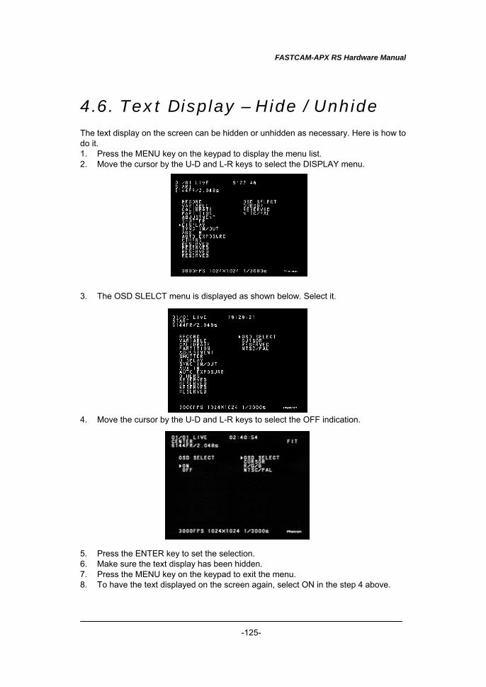
FASTCAM-APX RS Hardware Manual
-125-
4.6. Text Display – Hide / Unhide The text display on the screen can be hidden or unhidden as necessary. Here is how to do it. 1. Press the MENU key on the keypad to display the menu list. 2. Move the cursor by the U-D and L-R keys to select the DISPLAY menu. 3. The OSD SLELCT menu is displayed as shown below. Select it. 4. Move the cursor by the U-D and L-R keys to select the OFF indication. 5. Press the ENTER key to set the selection. 6. Make sure the text display has been hidden. 7. Press the MENU key on the keypad to exit the menu. 8. To have the text displayed on the screen again, select ON in the step 4 above.
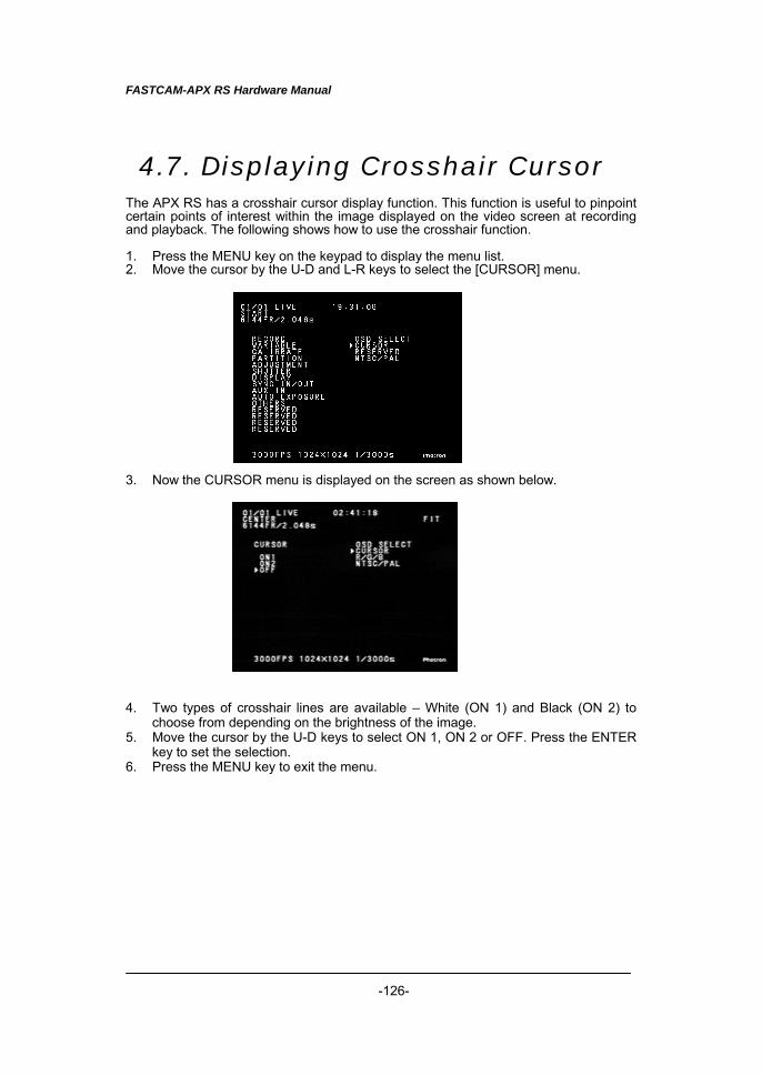
FASTCAM-APX RS Hardware Manual
-126-
4.7. Displaying Crosshair Cursor The APX RS has a crosshair cursor display function. This function is useful to pinpoint certain points of interest within the image displayed on the video screen at recording and playback. The following shows how to use the crosshair function. 1. Press the MENU key on the keypad to display the menu list. 2. Move the cursor by the U-D and L-R keys to select the [CURSOR] menu. 3. Now the CURSOR menu is displayed on the screen as shown below. 4. Two types of crosshair lines are available – White (ON 1) and Black (ON 2) to
choose from depending on the brightness of the image. 5. Move the cursor by the U-D keys to select ON 1, ON 2 or OFF. Press the ENTER
key to set the selection. 6. Press the MENU key to exit the menu.
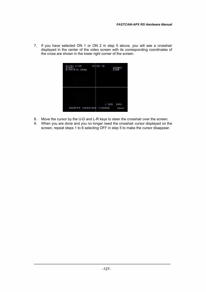
FASTCAM-APX RS Hardware Manual
-127-
7. If you have selected ON 1 or ON 2 in step 5 above, you will see a crosshair
displayed in the center of the video screen with its corresponding coordinates of the cross are shown in the lower right corner of the screen.
8. Move the cursor by the U-D and L-R keys to steer the crosshair over the screen. 9. When you are done and you no longer need the crosshair cursor displayed on the
screen, repeat steps 1 to 6 selecting OFF in step 5 to make the cursor disappear.
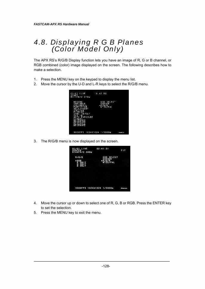
FASTCAM-APX RS Hardware Manual
-128-
4.8. Displaying R G B Planes (Color Model Only)
The APX RS’s R/G/B Display function lets you have an image of R, G or B channel, or RGB combined (color) image displayed on the screen. The following describes how to make a selection. 1. Press the MENU key on the keypad to display the menu list. 2. Move the cursor by the U-D and L-R keys to select the R/G/B menu. 3. The R/G/B menu is now displayed on the screen. 4. Move the cursor up or down to select one of R, G, B or RGB. Press the ENTER key
to set the selection. 5. Press the MENU key to exit the menu.
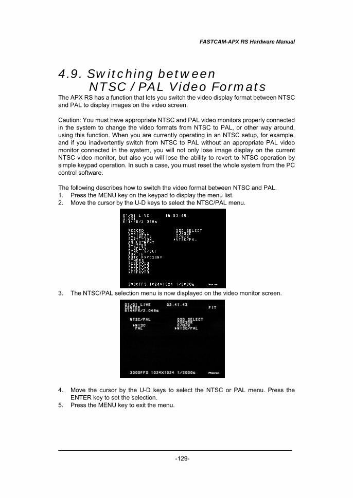
FASTCAM-APX RS Hardware Manual
-129-
4.9. Switching between NTSC / PAL Video Formats
The APX RS has a function that lets you switch the video display format between NTSC and PAL to display images on the video screen. Caution: You must have appropriate NTSC and PAL video monitors properly connected in the system to change the video formats from NTSC to PAL, or other way around, using this function. When you are currently operating in an NTSC setup, for example, and if you inadvertently switch from NTSC to PAL without an appropriate PAL video monitor connected in the system, you will not only lose image display on the current NTSC video monitor, but also you will lose the ability to revert to NTSC operation by simple keypad operation. In such a case, you must reset the whole system from the PC control software. The following describes how to switch the video format between NTSC and PAL. 1. Press the MENU key on the keypad to display the menu list. 2. Move the cursor by the U-D keys to select the NTSC/PAL menu. 3. The NTSC/PAL selection menu is now displayed on the video monitor screen. 4. Move the cursor by the U-D keys to select the NTSC or PAL menu. Press the
ENTER key to set the selection. 5. Press the MENU key to exit the menu.
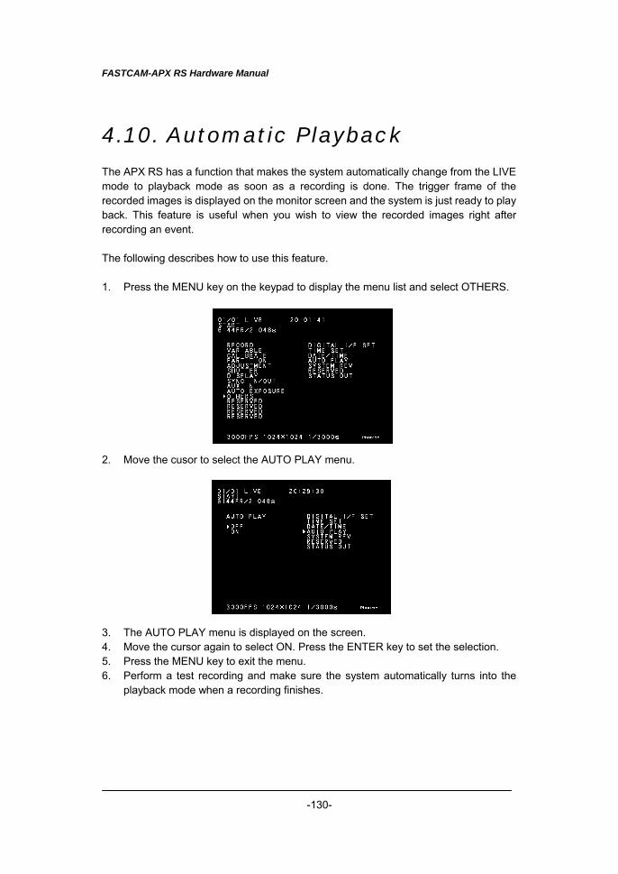
FASTCAM-APX RS Hardware Manual
-130-
4.10. Automatic Playback The APX RS has a function that makes the system automatically change from the LIVE mode to playback mode as soon as a recording is done. The trigger frame of the recorded images is displayed on the monitor screen and the system is just ready to play back. This feature is useful when you wish to view the recorded images right after recording an event. The following describes how to use this feature. 1. Press the MENU key on the keypad to display the menu list and select OTHERS. 2. Move the cusor to select the AUTO PLAY menu. 3. The AUTO PLAY menu is displayed on the screen. 4. Move the cursor again to select ON. Press the ENTER key to set the selection. 5. Press the MENU key to exit the menu. 6. Perform a test recording and make sure the system automatically turns into the
playback mode when a recording finishes.
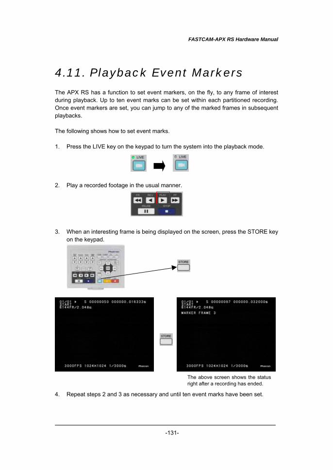
FASTCAM-APX RS Hardware Manual
-131-
4.11. Playback Event Markers The APX RS has a function to set event markers, on the fly, to any frame of interest during playback. Up to ten event marks can be set within each partitioned recording. Once event markers are set, you can jump to any of the marked frames in subsequent playbacks. The following shows how to set event marks. 1. Press the LIVE key on the keypad to turn the system into the playback mode. 2. Play a recorded footage in the usual manner. 3. When an interesting frame is being displayed on the screen, press the STORE key
on the keypad. 4. Repeat steps 2 and 3 as necessary and until ten event marks have been set.
The above screen shows the statusright after a recording has ended.
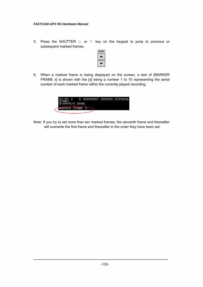
FASTCAM-APX RS Hardware Manual
-132-
5. Press the SHUTTER △ or ▽ key on the keypad to jump to previous or subsequent marked frames.
6. When a marked frame is being displayed on the screen, a text of [MARKER
FRAME x] is shown with the [x] being a number 1 to 10 representing the serial number of each marked frame within the currently played recording.
Note: If you try to set more than ten marked frames, the eleventh frame and thereafter
will overwrite the first frame and thereafter in the order they have been set.
FASTCAM-APX RS Hardware Manual
-133-
Chapter 5 Connecting APX RS to PC
5.1. Connecting APX RS to a PC 5.2. Connecting Multiple APX RS’s to a PC 5.3. Connecting Mixed Models of FASTACM Cameras
to a PC
FASTCAM-APX RS Hardware Manual
-134-
5.1. Connecting APX RS to a PC This section discusses the interfacing features of the APXRS. All functions of the APXRS camera can be controlled from a PC using a digital interface. An interface of your choice will be factory-installed at the time of shipping from Photron. See the PFV (Photron FASTCAM Viewer) manual for operation of the APXRS software.
5.1.1. APX RS. with IEEE1394 Interface To connect your APX RS camera to a PC via the IEEE1394 interface, use the provided IEEE1394 compatible cable that has a special connector connecting to the APX RS camera. The IEEE1394 interface on the APX RS camera is hot-pluggable as is the case with most peripheral devices for PC’s. Install the driver software in the PC to set it up after connecting the APX RS camera to it with the special IEEE1394 cable. For instructions for installation of and checking the driver software, refer to the “IEEE1394 Interface Driver Installtion” subsection (2.3.1.) of the FASTCAM Control Software Operation Manual. 5.1.2. Connection by Optical Interface Installing a Photron optical interface board in a PC and connecting an APX RS. camera processor to the PC using an optical cable, the camera can be controlled by the attached FASTCAM Control Software. 5.1.2.1. Specification
・ Supported OS: Windows2000/XP ・ Plug & Play: Supported ・ PCI bus: 32 bits (33 MHz) ・ Size: 174.0 mm × 106.5 mm ・ Standard: Photron’s proprietary protocol ・ Driver software: Photron driver ・ Maximum number of cameras connected: 64 ・ Supported application: PFV (Photron FASTCAM Viewer) ・ Operation environment: +5~+40 ℃, no condensation ・ Interface connector: SC connector ・ Connecting cable: Special optical fiber cable ・ Others: Power consumption 4 W Note: Data transfer speed depends on the specification of the PC being used.
FASTCAM-APX RS Hardware Manual
-135-
① Optical fiber cable specification Single-mode fiber (SMF), 9/125µm SMF Maximum transmission distance: 10 km (theoretical value derived from optical module) Multiple-mode fiber (MMF), 62.5/125µm MMF, 50/125µmMMF Maximum transmission distance: 550 meters (theoretical value derived from optical module) Connector shape: SC terminal attached on both ends Note: Attached standard optical fiber cable is a single mode fiber cable of 9/125µm SMF, 5 meter long. ② Bit rate: 1 GHz (125 Mbytes/s) on optical fiber cable 5.1.2.2. Installing IF Board in PC Before installing an IF board in PC, be sure to switch the PC off and unplug the power cord. Open the PC housing and install the IF board in an empty PCI slot. Make sure that the IF board has been installed firmly and squarely in the PCI slot. Loose installation may result in failure of either or both the PC and the board. 5.1.2.3. Connection between PC and Camera Processor Use a specified optical fiber cable to connect between the PC and APX RS. The optical interface for the APX RS is hot-pluggable. You can connect and disconnect it while power is on. Refer to the below figure for connection The optical interface has two terminals: TX (transmit) and RX (receive). When connecting one or more APX RS’s by optical interface, opposing terminals must be connected as if forming a loop as shown in the below figures. Optical cables do not have polarity and can be connected in any direction.
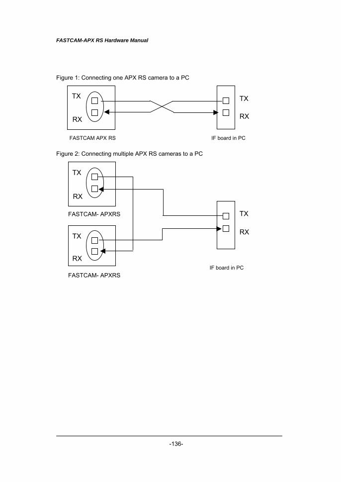
FASTCAM-APX RS Hardware Manual
-136-
Figure 1: Connecting one APX RS camera to a PC
FASTCAM APX RS IF board in PC Figure 2: Connecting multiple APX RS cameras to a PC
FASTCAM- APXRS
IF board in PC FASTCAM- APXRS
TX
RX
TX
RX
TX
RX
TX
RX
TX
RX
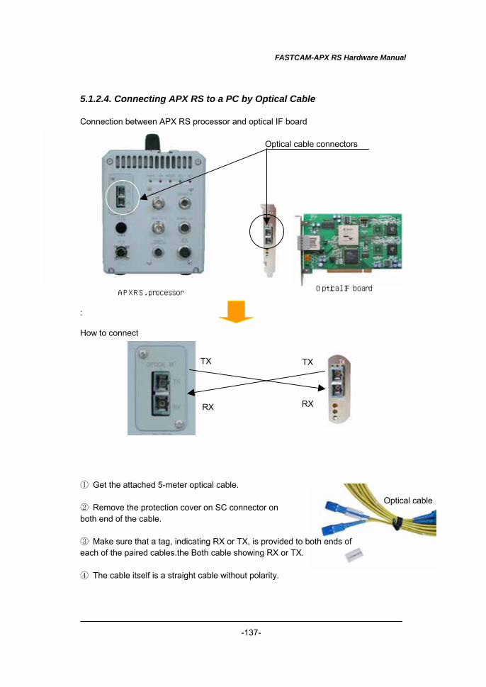
FASTCAM-APX RS Hardware Manual
-137-
5.1.2.4. Connecting APX RS to a PC by Optical Cable Connection between APX RS processor and optical IF board : How to connect
① Get the attached 5-meter optical cable. ② Remove the protection cover on SC connector on both end of the cable. ③ Make sure that a tag, indicating RX or TX, is provided to both ends of each of the paired cables.the Both cable showing RX or TX. ④ The cable itself is a straight cable without polarity.
Optical IF board APXRS. processor
Optical cable connectors
Optical cable
RX
TX
RX
TX
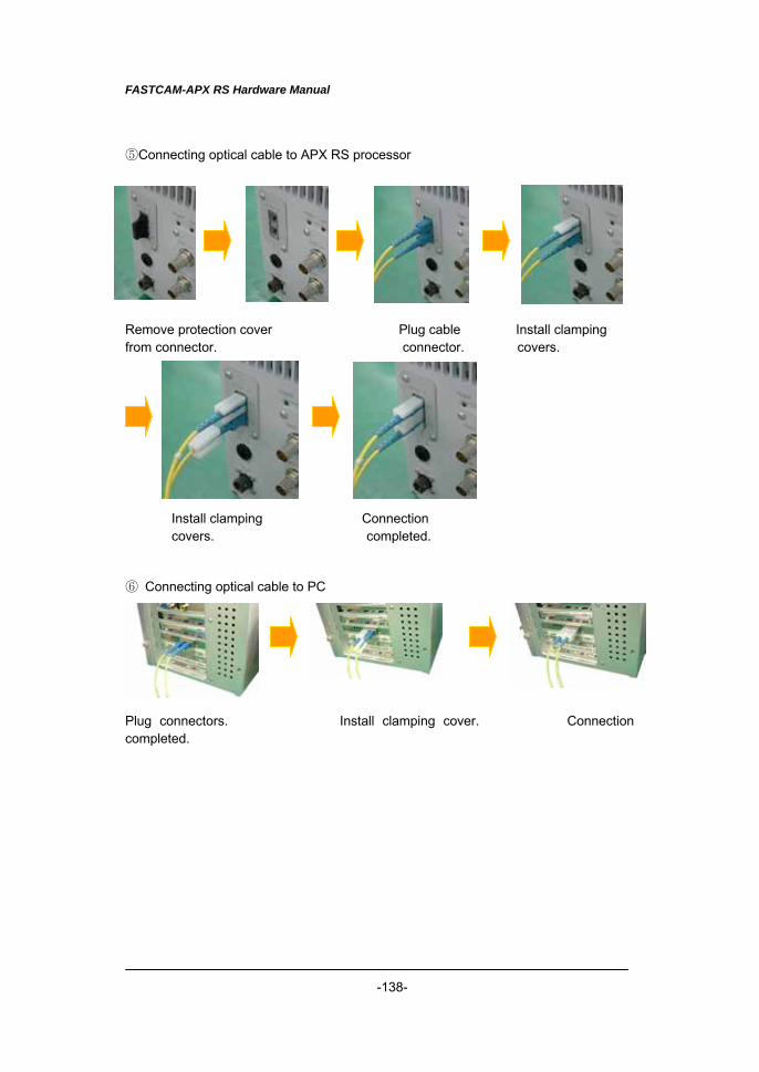
FASTCAM-APX RS Hardware Manual
-138-
⑤Connecting optical cable to APX RS processor Remove protection cover Plug cable Install clamping from connector. connector. covers.
Install clamping Connection covers. completed. ⑥ Connecting optical cable to PC Plug connectors. Install clamping cover. Connection completed.
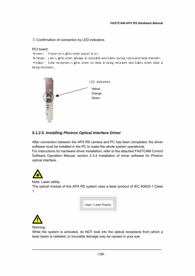
FASTCAM-APX RS Hardware Manual
-139-
⑦ Confirmation of connection by LED indicators PCI board ・Green: Power on: Lights when power is on.
・Orange: Link: Lights when linkage is complete and blinks during command/data transfer.
・Yellow: Date reception: Lights when no data is being received and blinks when data is
being received..
5.1.2.5. Installing Photron Optical Interface Driver After connection between the APX RS camera and PC has been completed, the driver software must be installed in the PC to make the whole system operational. For instructions for hardware driver installation, refer to the attached FASTCAM Control Software Operation Manual, section 2.3.4 Installation of driver software for Photron optical interface. Note: Laser safety The optical module of this APX RS system uses a laser product of IEC 60825-1 Class 1. Warning: While the system is activated, do NOT look into the optical receptacle from which a laser beam is radiated, or incurable damage may be caused in your eye.
Class 1 Laser Product
YellowOrangeGreen
LED indicators
FASTCAM-APX RS Hardware Manual
-140-
5.1.3. Using Giga Bit Ethernet Interface To use the Giga Bit Ethernet interface to connect the FASTCAM-APX RS camera to a PC, connect the camera processor to a 1000BASE-T compatible interface board (readily available in the market) using a LAN cable. Use a UTP or STP type LAN cable with CAT5E or higher specification. The maximum length allowed for the cable connecting between the PC and the camera is 100 meters. Up to 64 cameras can be connected to one PC using a swithcing hub that is 1000BASE-T compatible. The maximum length of the cable connecting between the camera (and the PC) and the switching hub is 100 meters. After connecting between the camera(s) and the PC with a LAN cable, the following setup is necessary: ○ On the cameras ・ IP addresss ○ On the PC ・ IP address ・ Packet size ・ Timeout ・ T/R (transmission-receiving) ports For setting the IP address of the camera, refer to Section 5.1.3.3 (Setting camera IP address) of this manual. For setting the PC, see the separate FASTCAM Control Software Operation Manual, Section 5 (Setting PFV environment), Section 5.1 (Environment setting dialog) and Section 5.1.5. (IP address registration) for details. Note: The FASTCAM-APX RS is compatible with 1000BASE-T only. To use the camera with 10BASE-T or 100BASE-T, system connection via a switching hub that is compatible with 1000BASE-T is needed. Note: The factory setting of IP address is as follow:
IP ADDRESS: 192.168.0.10 NETMASK: 255.255.255.0 GATEWAY ADDRESS: 0.0.0.0 PORT: 2000 (fixed, not changeable)
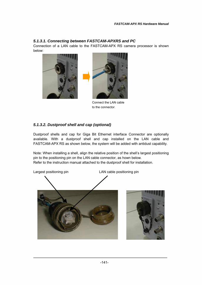
FASTCAM-APX RS Hardware Manual
-141-
5.1.3.1. Connecting between FASTCAM-APXRS and PC Connection of a LAN cable to the FASTCAM-APX RS camera processor is shown below: Connect the LAN cable
to the connector. 5.1.3.2. Dustproof shell and cap (optional) Dustproof shells and cap for Giga Bit Ethernet interface Connector are optionally available. With a dustproof shell and cap installed on the LAN cable and FASTCAM-APX RS as shown below, the system will be added with antidust capability. Note: When installing a shell, align the relative position of the shell’s largest positioning pin to the positioning pin on the LAN cable connector, as hown below. Refer to the instruction manual attached to the dustproof shell for installation. Largest positioning pin LAN cable positioning pin
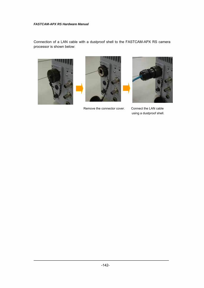
FASTCAM-APX RS Hardware Manual
-142-
Connection of a LAN cable with a dustproof shell to the FASTCAM-APX RS camera processor is shown below: Remove the connector cover. Connect the LAN cable
using a dustproof shell.
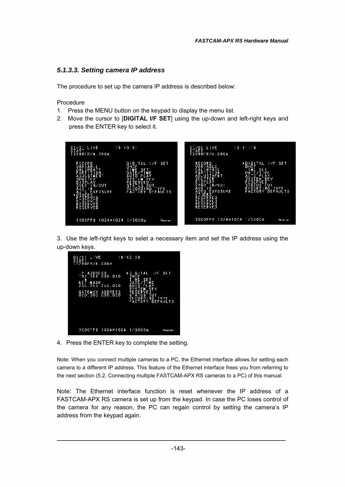
FASTCAM-APX RS Hardware Manual
-143-
5.1.3.3. Setting camera IP address The procedure to set up the camera IP address is described below: Procedure 1. Press the MENU button on the keypad to display the menu list. 2. Move the cursor to [DIGITAL I/F SET] using the up-down and left-right keys and
press the ENTER key to select it. 3.Use the left-right keys to selet a necessary item and set the IP address using the up-down keys. 4.Press the ENTER key to complete the setting. Note: When you connect multiple cameras to a PC, the Ethernet interface allows for setting each camera to a different IP address. This feature of the Ethernet interface frees you from referring to the next section (5.2. Connecting multiple FASTCAM-APX RS cameras to a PC) of this manual. Note: The Ethernet interface function is reset whenever the IP address of a FASTCAM-APX RS camera is set up from the keypad. In case the PC loses control of the camera for any reason, the PC can regain control by setting the camera’s IP address from the keypad again.
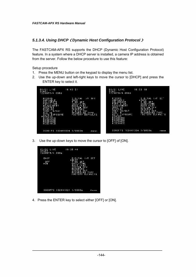
FASTCAM-APX RS Hardware Manual
-144-
5.1.3.4. Using DHCP(Dynamic Host Configuration Protocol) The FASTCAM-APX RS supports the DHCP (Dynamic Host Configuration Protocol) feature. In a system where a DHCP server is installed, a camera IP address is obtained from the server. Follow the below procedure to use this feature: Setup procedure 1. Press the MENU button on the keypad to display the menu list. 2. Use the up-down and left-right keys to move the cursor to [DHCP] and press the
ENTER key to select it. 3. Use the up-down keys to move the cursor to [OFF] of [ON]. 4.Press the ENTER key to select either [OFF] or [ON].
FASTCAM-APX RS Hardware Manual
-145-
・OFF, when selected, makes the IP address set in the previous subsection 5.1.3.3. (Setting camera IP address) effective. ・ON, when selected, obtains an IP address from the DHCP server and makes it
effective. When a DHCP server is not connected, an IP address is obtained as soon as a server is connected. The obtained IP address can be confirmed using the [DIGITAL I/F SET] menu that is used in the previous subsection 5.1.3.3. (Setting camera IP address). However, no change of the obtained IP addrss is possible.
Note: When the DHCP feature is set ON, the PFV must be set up in the menu as follows: Menu > [Option] > [Configuration] > Ether Network [Setup] > [IP Address Register] > [Auto detection]
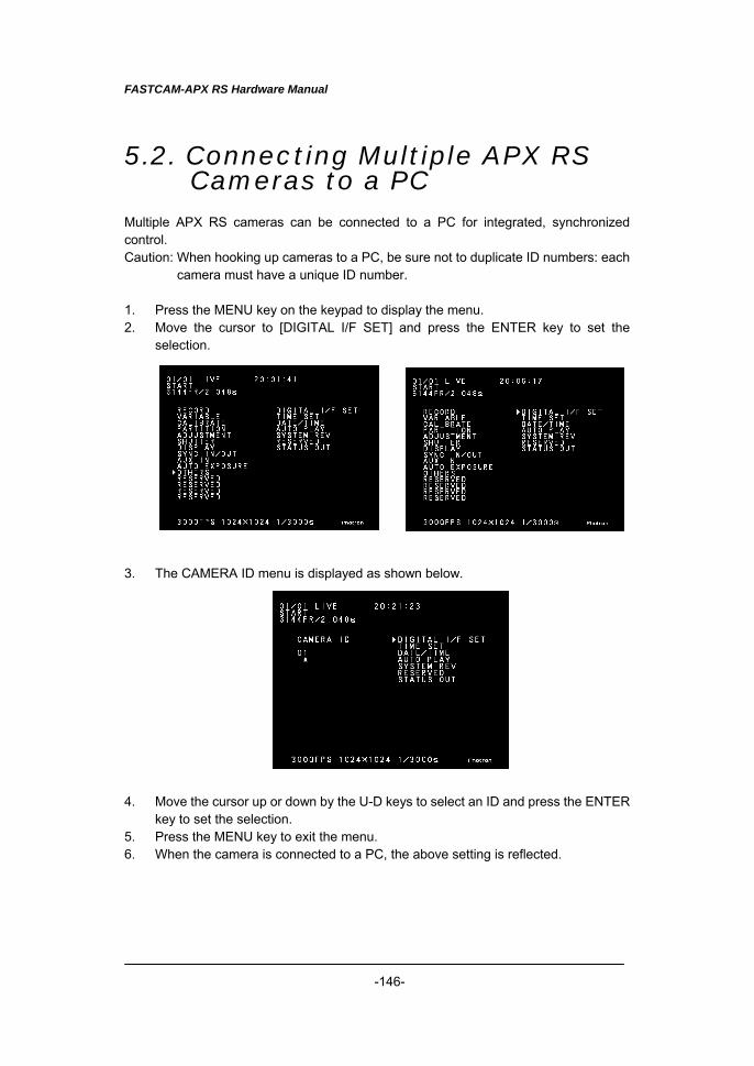
FASTCAM-APX RS Hardware Manual
-146-
5.2. Connecting Multiple APX RS Cameras to a PC
Multiple APX RS cameras can be connected to a PC for integrated, synchronized control. Caution: When hooking up cameras to a PC, be sure not to duplicate ID numbers: each
camera must have a unique ID number. 1. Press the MENU key on the keypad to display the menu. 2. Move the cursor to [DIGITAL I/F SET] and press the ENTER key to set the
selection.
3. The CAMERA ID menu is displayed as shown below.
4. Move the cursor up or down by the U-D keys to select an ID and press the ENTER
key to set the selection. 5. Press the MENU key to exit the menu. 6. When the camera is connected to a PC, the above setting is reflected.
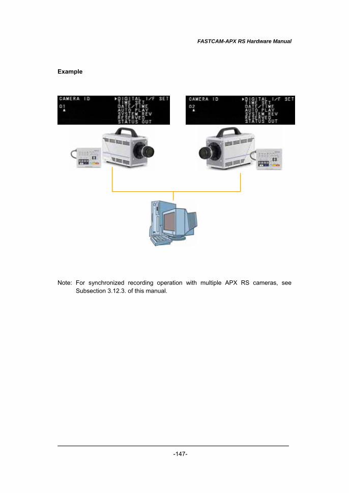
FASTCAM-APX RS Hardware Manual
-147-
Example Note: For synchronized recording operation with multiple APX RS cameras, see
Subsection 3.12.3. of this manual.
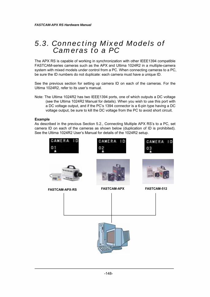
FASTCAM-APX RS Hardware Manual
-148-
5.3. Connecting Mixed Models of Cameras to a PC
The APX RS is capable of working in synchronization with other IEEE1394 compatible FASTCAM-series cameras such as the APX and Ultima 1024R2 in a multiple-camera system with mixed models under control from a PC. When connecting cameras to a PC, be sure the ID numbers do not duplicate: each camera must have a unique ID. See the previous section for setting up camera ID on each of the cameras. For the Ultima 1024R2, refer to its user’s manual. Note: The Ultima 1024R2 has two IEEE1394 ports, one of which outputs a DC voltage
(see the Ultima 1024R2 Manual for details). When you wish to use this port with a DC voltage output, and if the PC’s 1394 connector is a 6-pin type having a DC voltage output, be sure to kill the DC voltage from the PC to avoid short circuit.
Example As described in the previous Section 5.2., Connecting Multiple APX RS’s to a PC, set camera ID on each of the cameras as shown below (duplication of ID is prohibited). See the Ultima 1024R2 User’s Manual for details of the 1024R2 setup.
FASTCAM-APX-RS FASTCAM-APX FASTCAM-512
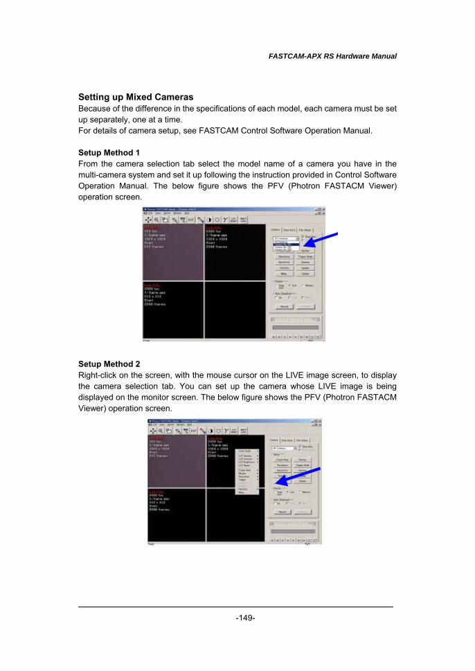
FASTCAM-APX RS Hardware Manual
-149-
Setting up Mixed Cameras Because of the difference in the specifications of each model, each camera must be set up separately, one at a time. For details of camera setup, see FASTCAM Control Software Operation Manual. Setup Method 1 From the camera selection tab select the model name of a camera you have in the multi-camera system and set it up following the instruction provided in Control Software Operation Manual. The below figure shows the PFV (Photron FASTACM Viewer) operation screen.
Setup Method 2 Right-click on the screen, with the mouse cursor on the LIVE image screen, to display the camera selection tab. You can set up the camera whose LIVE image is being displayed on the monitor screen. The below figure shows the PFV (Photron FASTACM Viewer) operation screen.
FASTCAM-APX RS Hardware Manual
-150-
Chapter 6 Specifications
6.1. Specifications 6.2. Mechanical Data 6.3. How to Care Lenses
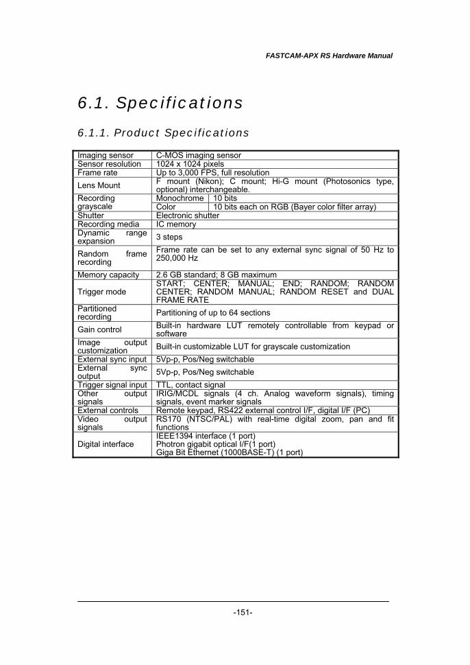
FASTCAM-APX RS Hardware Manual
-151-
6.1. Specifications
6.1.1. Product Specifications Imaging sensor C-MOS imaging sensor Sensor resolution 1024 x 1024 pixels Frame rate Up to 3,000 FPS, full resolution Lens Mount F mount (Nikon); C mount; Hi-G mount (Photosonics type,
optional) interchangeable. Monochrome 10 bits Recording
grayscale Color 10 bits each on RGB (Bayer color filter array) Shutter Electronic shutter Recording media IC memory Dynamic range expansion 3 steps
Random frame recording
Frame rate can be set to any external sync signal of 50 Hz to 250,000 Hz
Memory capacity 2.6 GB standard; 8 GB maximum
Trigger mode START; CENTER; MANUAL; END; RANDOM; RANDOM CENTER; RANDOM MANUAL; RANDOM RESET and DUAL FRAME RATE
Partitioned recording Partitioning of up to 64 sections
Gain control Built-in hardware LUT remotely controllable from keypad or software
Image output customization Built-in customizable LUT for grayscale customization External sync input 5Vp-p, Pos/Neg switchable External sync output 5Vp-p, Pos/Neg switchable Trigger signal input TTL, contact signal Other output signals
IRIG/MCDL signals (4 ch. Analog waveform signals), timing signals, event marker signals
External controls Remote keypad, RS422 external control I/F, digital I/F (PC) Video output signals
RS170 (NTSC/PAL) with real-time digital zoom, pan and fit functions
Digital interface IEEE1394 interface (1 port) Photron gigabit optical I/F(1 port) Giga Bit Ethernet (1000BASE-T) (1 port)
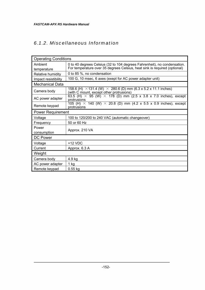
FASTCAM-APX RS Hardware Manual
-152-
6.1.2. Miscellaneous Information Operating Conditions Ambient temperature
0 to 40 degrees Celsius (32 to 104 degrees Fahrenheit), no condensation. For temperature over 35 degrees Celsius, heat sink is required (optional)
Relative humidity 0 to 85 %, no condensation Impact resistibility 100 G, 10 msec, 6 axes (exept for AC power adapter unit) Mechanical Data
Camera body 158.6 (H) ×131.4 (W) × 280.6 (D) mm (6.3 x 5.2 x 11.1 inches) (with C mount, except other protrusions)
AC power adapter 63.5 (H) × 95 (W) × 178 (D) mm (2.5 x 3.8 x 7.0 inches), except protrusions
Remote keypad 105 (H) × 140 (W) × 20.8 (D) mm (4.2 x 5.5 x 0.9 inches), except protrusions
Power Requirement Voltage 100 to 120/200 to 240 VAC (automatic changeover) Frequency 50 or 60 Hz Power consumption Approx. 210 VA
DC Power Voltage +12 VDC Current Approx. 6.3 A Weight Camera body 4.9 kg AC power adapter 1 kg Remote keypad 0.55 kg
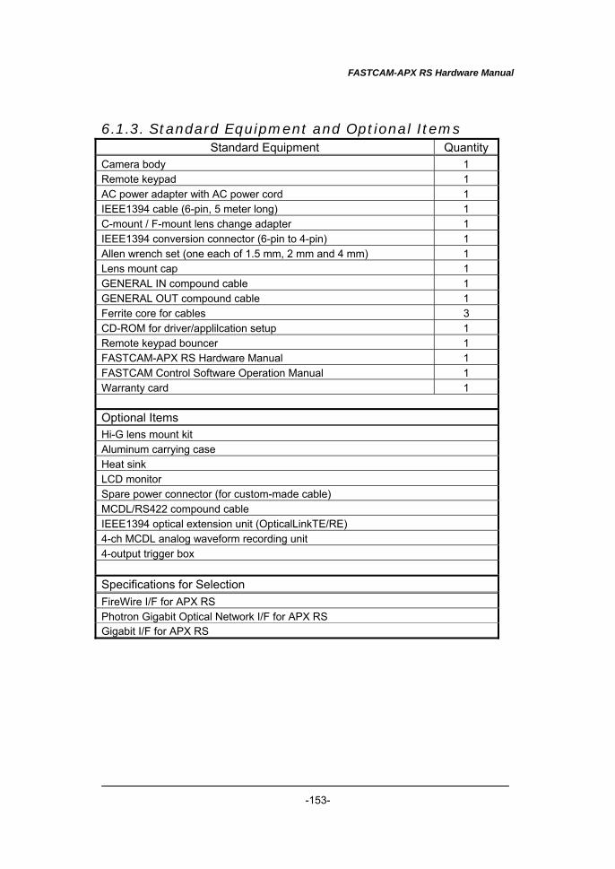
FASTCAM-APX RS Hardware Manual
-153-
6.1.3. Standard Equipment and Optional Items Standard Equipment Quantity
Camera body 1 Remote keypad 1 AC power adapter with AC power cord 1 IEEE1394 cable (6-pin, 5 meter long) 1 C-mount / F-mount lens change adapter 1 IEEE1394 conversion connector (6-pin to 4-pin) 1 Allen wrench set (one each of 1.5 mm, 2 mm and 4 mm) 1 Lens mount cap 1 GENERAL IN compound cable 1 GENERAL OUT compound cable 1 Ferrite core for cables 3 CD-ROM for driver/applilcation setup 1 Remote keypad bouncer 1 FASTCAM-APX RS Hardware Manual 1 FASTCAM Control Software Operation Manual 1 Warranty card 1 Optional Items Hi-G lens mount kit Aluminum carrying case Heat sink LCD monitor Spare power connector (for custom-made cable) MCDL/RS422 compound cable IEEE1394 optical extension unit (OpticalLinkTE/RE) 4-ch MCDL analog waveform recording unit 4-output trigger box Specifications for Selection FireWire I/F for APX RS Photron Gigabit Optical Network I/F for APX RS Gigabit I/F for APX RS
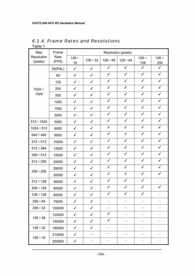
FASTCAM-APX RS Hardware Manual
-154-
6.1.4. Frame Rates and Resolutions Table 1
Resolution (pixels) Max Resolution
(pixels)
Frame Rate (FPS)
128×16
128×32 128×48 128×64 128×128
128×256
50(PAL) ✓ ✓ ✓ ✓ ✓ ✓
60 ✓ ✓ ✓ ✓ ✓ ✓
125 ✓ ✓ ✓ ✓ ✓ ✓
250 ✓ ✓ ✓ ✓ ✓ ✓
500 ✓ ✓ ✓ ✓ ✓ ✓
1000 ✓ ✓ ✓ ✓ ✓ ✓
1500 ✓ ✓ ✓ ✓ ✓ ✓
1024×1024
3000 ✓ ✓ ✓ ✓ ✓ ✓
512×1024 5000 ✓ ✓ ✓ ✓ ✓ ✓
1024×512 6000 ✓ ✓ ✓ ✓ ✓ ✓
640×480 9000 ✓ ✓ ✓ ✓ ✓ ✓
512×512 10000 ✓ ✓ ✓ ✓ ✓ ✓
512×384 12000 ✓ ✓ ✓ ✓ ✓ ✓
256×512 15000 ✓ ✓ ✓ ✓ ✓ ✓
512×256 20000 ✓ ✓ ✓ ✓ ✓ ✓
28000 ✓ ✓ ✓ ✓ ✓ ✓ 256×256
30000 ✓ ✓ ✓ ✓ ✓ ✓
512×128 36000 ✓ ✓ ✓ ✓ ✓ -
256×128 50000 ✓ ✓ ✓ ✓ ✓ ✓
128×128 60000 ✓ ✓ ✓ ✓ ✓ -
256×64 75000 ✓ ✓ - - - - 256×32 100000 ✓ ✓ - - - -
125000 ✓ ✓ ✓ - - - 128×48
150000 ✓ ✓ ✓ - - - 128×32 180000 ✓ ✓ - - - -
210000 ✓ - - - - - 128×16
250000 ✓ - - - - -
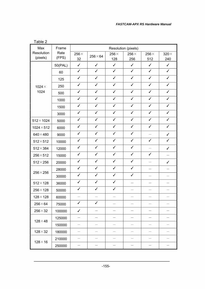
FASTCAM-APX RS Hardware Manual
-155-
Table 2 Resolution (pixels) Max
Resolution (pixels)
Frame Rate (FPS)
256×32
256×64 256×128
256×256
256×512
320×240
50(PAL) ✓ ✓ ✓ ✓ ✓ ✓ 60 ✓ ✓ ✓ ✓ ✓ ✓
125 ✓ ✓ ✓ ✓ ✓ ✓
250 ✓ ✓ ✓ ✓ ✓ ✓
500 ✓ ✓ ✓ ✓ ✓ ✓
1000 ✓ ✓ ✓ ✓ ✓ ✓
1500 ✓ ✓ ✓ ✓ ✓ ✓
1024×1024
3000 ✓ ✓ ✓ ✓ ✓ ✓
512×1024 5000 ✓ ✓ ✓ ✓ ✓ ✓
1024×512 6000 ✓ ✓ ✓ ✓ ✓ ✓
640×480 9000 ✓ ✓ ✓ ✓ - ✓
512×512 10000 ✓ ✓ ✓ ✓ ✓ ✓
512×384 12000 ✓ ✓ ✓ ✓ - ✓
256×512 15000 ✓ ✓ ✓ ✓ ✓ -
512×256 20000 ✓ ✓ ✓ ✓ - ✓
28000 ✓ ✓ ✓ ✓ - - 256×256
30000 ✓ ✓ ✓ ✓ - - 512×128 36000 ✓ ✓ ✓ - - - 256×128 50000 ✓ ✓ ✓ - - - 128×128 60000 - - - - - - 256×64 75000 ✓ ✓ - - - - 256×32 100000 ✓ - - - - -
125000 - - - - - - 128×48
150000 - - - - - - 128×32 180000 - - - - - -
210000 - - - - - - 128×16
250000 - - - - - -

FASTCAM-APX RS Hardware Manual
-156-
Table 3 Resolution (pixels) Max
Resolution (pixels)
Frame Rate (FPS)
512×64
512×128
512×256
512×384
512×512
512× 1024
50(PAL) ✓ ✓ ✓ ✓ ✓ ✓
60 ✓ ✓ ✓ ✓ ✓ ✓
125 ✓ ✓ ✓ ✓ ✓ ✓
250 ✓ ✓ ✓ ✓ ✓ ✓
500 ✓ ✓ ✓ ✓ ✓ ✓
1000 ✓ ✓ ✓ ✓ ✓ ✓
1500 ✓ ✓ ✓ ✓ ✓ ✓
1024×1024
3000 ✓ ✓ ✓ ✓ ✓ ✓
512×1024 5000 ✓ ✓ ✓ ✓ ✓ ✓
1024×512 6000 ✓ ✓ ✓ ✓ ✓ - 640×480 9000 ✓ ✓ ✓ ✓ - - 512×512 10000 ✓ ✓ ✓ ✓ ✓ - 512×384 12000 ✓ ✓ ✓ ✓ - - 256×512 15000 - - - - - - 512×256 20000 ✓ ✓ ✓ - - -
28000 - - - - - - 256×256
30000 - - - - - - 512×128 36000 ✓ ✓ - - - - 256×128 50000 - - - - - - 128×128 60000 - - - - - - 256×64 75000 - - - - - - 256×32 100000 - - - - - -
125000 - - - - - - 128×48
150000 - - - - - - 128×32 180000 - - - - - -
210000 - - - - - - 128×16
250000 - - - - - -
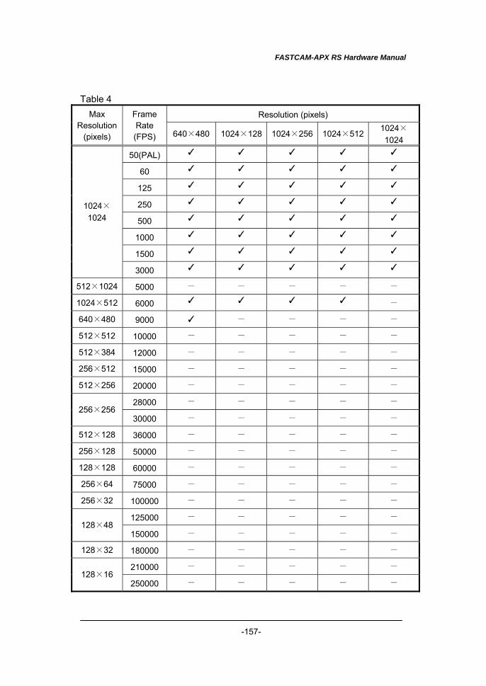
FASTCAM-APX RS Hardware Manual
-157-
Table 4 Resolution (pixels) Max
Resolution (pixels)
Frame Rate (FPS) 640×480 1024×128 1024×256 1024×512 1024×
1024
50(PAL) ✓ ✓ ✓ ✓ ✓
60 ✓ ✓ ✓ ✓ ✓
125 ✓ ✓ ✓ ✓ ✓
250 ✓ ✓ ✓ ✓ ✓
500 ✓ ✓ ✓ ✓ ✓
1000 ✓ ✓ ✓ ✓ ✓
1500 ✓ ✓ ✓ ✓ ✓
1024×1024
3000 ✓ ✓ ✓ ✓ ✓
512×1024 5000 - - - - - 1024×512 6000 ✓ ✓ ✓ ✓ - 640×480 9000 ✓ - - - - 512×512 10000 - - - - - 512×384 12000 - - - - - 256×512 15000 - - - - - 512×256 20000 - - - - -
28000 - - - - - 256×256
30000 - - - - - 512×128 36000 - - - - - 256×128 50000 - - - - - 128×128 60000 - - - - - 256×64 75000 - - - - - 256×32 100000 - - - - -
125000 - - - - - 128×48
150000 - - - - - 128×32 180000 - - - - -
210000 - - - - - 128×16
250000 - - - - -
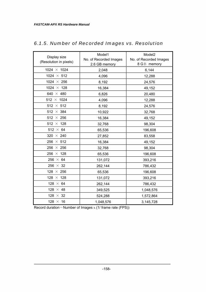
FASTCAM-APX RS Hardware Manual
-158-
6.1.5. Number of Recorded Images vs. Resolution
Display size (Resolution in pixels)
Model1 No. of Recorded Images
2.6 GB memory
Model2 No. of Recorded Images
8 GB memory 1024 × 1024 2,048 6,144 1024 × 512 4,096 12,288 1024 × 256 8,192 24,576 1024 × 128 16,384 49,152 640 × 480 6,826 20,480
512 × 1024 4,096 12,288 512 × 512 8,192 24,576 512 × 384 10,922 32,768 512 × 256 16,384 49,152 512 × 128 32,768 98,304 512 × 64 65,536 196,608 320 × 240 27,852 83,558 256 × 512 16,384 49,152 256 × 256 32,768 98,304 256 × 128 65,536 196,608 256 × 64 131,072 393,216 256 × 32 262,144 786,432 128 × 256 65,536 196,608 128 × 128 131,072 393,216 128 × 64 262,144 786,432 128 × 48 349,525 1,048,576 128 × 32 524,288 1,572,864 128 × 16 1,048,576 3,145,728
Record duration=Number of Imagesx(1/ frame rate (FPS))
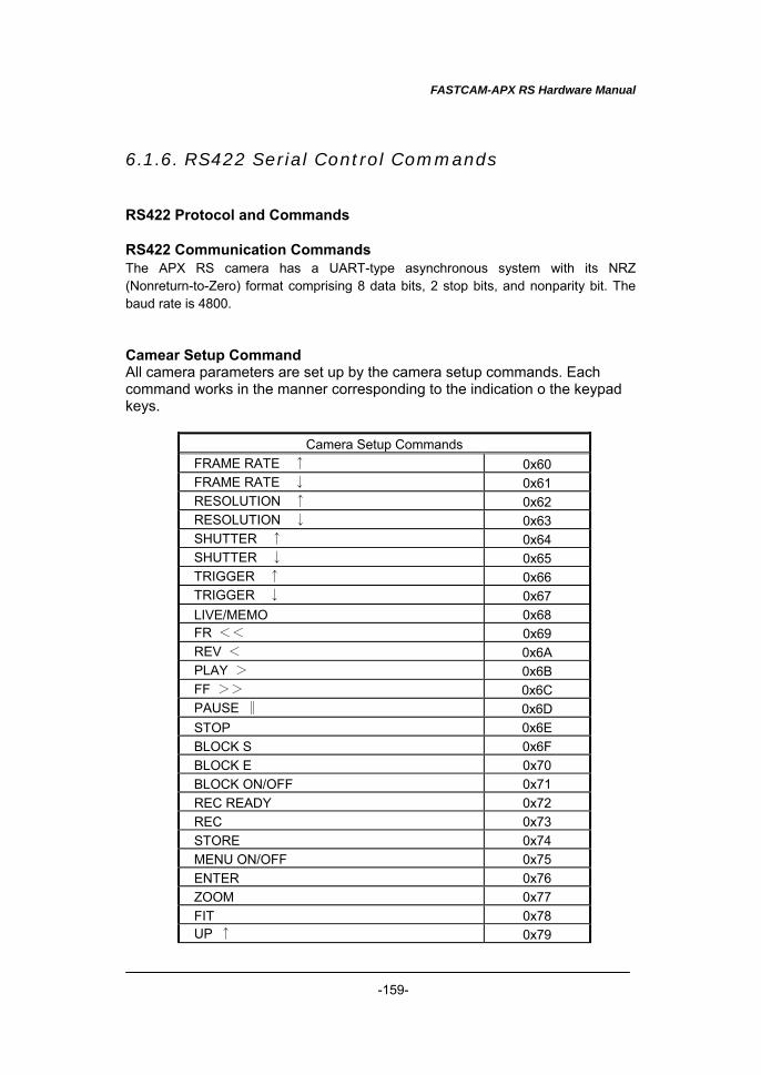
FASTCAM-APX RS Hardware Manual
-159-
6.1.6. RS422 Serial Control Commands RS422 Protocol and Commands RS422 Communication Commands The APX RS camera has a UART-type asynchronous system with its NRZ (Nonreturn-to-Zero) format comprising 8 data bits, 2 stop bits, and nonparity bit. The baud rate is 4800. Camear Setup Command All camera parameters are set up by the camera setup commands. Each command works in the manner corresponding to the indication o the keypad keys.
Camera Setup Commands FRAME RATE ↑ 0x60 FRAME RATE ↓ 0x61 RESOLUTION ↑ 0x62 RESOLUTION ↓ 0x63 SHUTTER ↑ 0x64 SHUTTER ↓ 0x65 TRIGGER ↑ 0x66 TRIGGER ↓ 0x67 LIVE/MEMO 0x68 FR << 0x69 REV < 0x6A PLAY > 0x6B FF >> 0x6C PAUSE ∥ 0x6D STOP 0x6E BLOCK S 0x6F BLOCK E 0x70 BLOCK ON/OFF 0x71 REC READY 0x72 REC 0x73 STORE 0x74 MENU ON/OFF 0x75 ENTER 0x76 ZOOM 0x77 FIT 0x78 UP ↑ 0x79
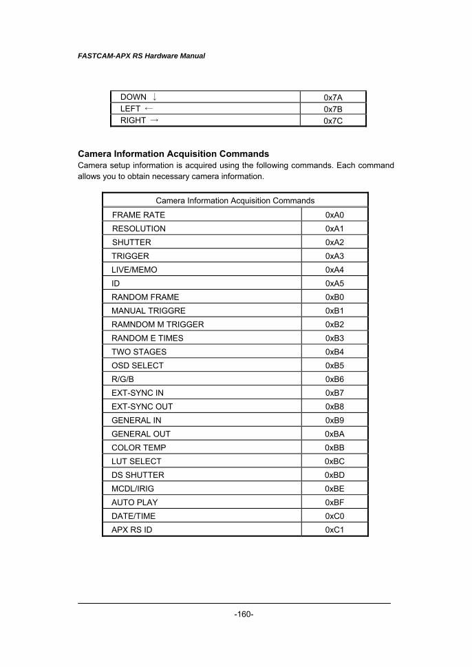
FASTCAM-APX RS Hardware Manual
-160-
DOWN ↓ 0x7A LEFT ← 0x7B RIGHT → 0x7C
Camera Information Acquisition Commands Camera setup information is acquired using the following commands. Each command allows you to obtain necessary camera information.
Camera Information Acquisition Commands
FRAME RATE 0xA0 RESOLUTION 0xA1 SHUTTER 0xA2 TRIGGER 0xA3 LIVE/MEMO 0xA4 ID 0xA5 RANDOM FRAME 0xB0 MANUAL TRIGGRE 0xB1 RAMNDOM M TRIGGER 0xB2 RANDOM E TIMES 0xB3 TWO STAGES 0xB4 OSD SELECT 0xB5 R/G/B 0xB6 EXT-SYNC IN 0xB7 EXT-SYNC OUT 0xB8 GENERAL IN 0xB9 GENERAL OUT 0xBA COLOR TEMP 0xBB LUT SELECT 0xBC DS SHUTTER 0xBD MCDL/IRIG 0xBE AUTO PLAY 0xBF DATE/TIME 0xC0 APX RS ID 0xC1
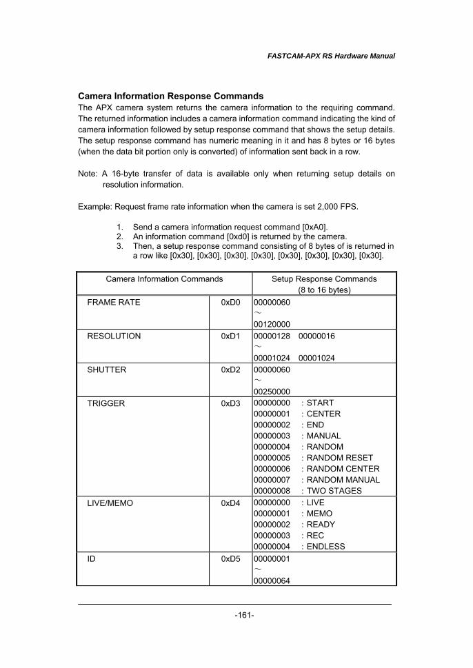
FASTCAM-APX RS Hardware Manual
-161-
Camera Information Response Commands The APX camera system returns the camera information to the requiring command. The returned information includes a camera information command indicating the kind of camera information followed by setup response command that shows the setup details. The setup response command has numeric meaning in it and has 8 bytes or 16 bytes (when the data bit portion only is converted) of information sent back in a row. Note: A 16-byte transfer of data is available only when returning setup details on
resolution information. Example: Request frame rate information when the camera is set 2,000 FPS.
1. Send a camera information request command [0xA0]. 2. An information command [0xd0] is returned by the camera. 3. Then, a setup response command consisting of 8 bytes of is returned in
a row like [0x30], [0x30], [0x30], [0x30], [0x30], [0x30], [0x30], [0x30].
Camera Information Commands Setup Response Commands (8 to 16 bytes)
FRAME RATE 0xD0 00000060 ~ 00120000
RESOLUTION 0xD1 00000128 00000016 ~ 00001024 00001024
SHUTTER 0xD2 00000060 ~ 00250000
TRIGGER 0xD3 00000000 :START 00000001 :CENTER 00000002 :END 00000003 :MANUAL 00000004 :RANDOM 00000005 :RANDOM RESET 00000006 :RANDOM CENTER 00000007 :RANDOM MANUAL 00000008 :TWO STAGES
LIVE/MEMO 0xD4 00000000 :LIVE 00000001 :MEMO 00000002 :READY 00000003 :REC 00000004 :ENDLESS
ID 0xD5 00000001 ~ 00000064
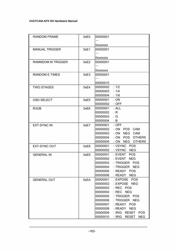
FASTCAM-APX RS Hardware Manual
-162-
RANDOM FRAME 0xE0 00000001 ~ 0xxxxxxx
MANUAL TRIGGER 0xE1 00000001 ~ 0xxxxxxx
RAMNDOM M TRIGGER 0xE2 00000001 ~ 0xxxxxxx
RANDOM E TIMES 0xE3 00000001 ~ 00000010
TWO STAGES 0xE4 00000002 :1/2 00000003 :1/4 00000004 :1/8
OSD SELECT 0xE5 00000001 :ON 00000002 :OFF
R/G/B 0xE6 00000001 :ALL 00000002 :R 00000003 :G 00000004 :B
EXT-SYNC IN 0xE7 00000001 :OFF 00000002 :ON POS CAM 00000003 :ON NEG CAM 00000004 :ON POS OTHERS 00000005 :ON NEG OTHERS
EXT-SYNC OUT 0xE8 00000001 :VSYNC POS 00000002 :VSYNC NEG
GENERAL IN 0xE9 00000001 :EVENT POS 00000002 :EVENT NEG 00000003 :TRIGGER POS 00000004 :TRIGGER NEG 00000005 :READY POS 00000006 :READY NEG
GENERAL OUT 0xEA 00000001 :EXPOSE POS 00000002 :EXPOSE NEG 00000003 :REC POS 00000004 :REC NEG 00000005 :TRIGGER POS 00000006 :TRIGGER NEG 00000007 :READY POS 00000008 :READY NEG 00000009 :IRIG RESET POS 00000010 :IRIG RESET NEG
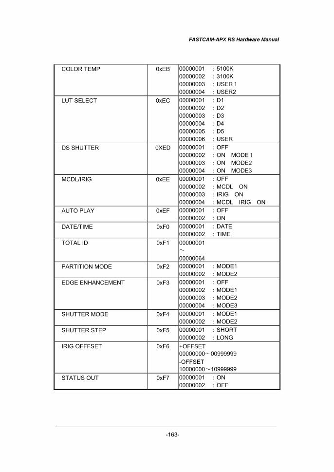
FASTCAM-APX RS Hardware Manual
-163-
COLOR TEMP 0xEB 00000001 :5100K 00000002 :3100K 00000003 :USER1 00000004 :USER2
LUT SELECT 0xEC 00000001 :D1 00000002 :D2 00000003 :D3 00000004 :D4 00000005 :D5 00000006 :USER
DS SHUTTER 0XED 00000001 :OFF 00000002 :ON MODE1 00000003 :ON MODE2 00000004 :ON MODE3
MCDL/IRIG 0xEE 00000001 :OFF 00000002 :MCDL ON 00000003 :IRIG ON 00000004 :MCDL IRIG ON
AUTO PLAY 0xEF 00000001 :OFF 00000002 :ON
DATE/TIME 0xF0 00000001 :DATE 00000002 :TIME
TOTAL ID 0xF1 00000001 ~ 00000064
PARTITION MODE 0xF2 00000001 :MODE1 00000002 :MODE2
EDGE ENHANCEMENT 0xF3 00000001 :OFF 00000002 :MODE1 00000003 :MODE2 00000004 :MODE3
SHUTTER MODE 0xF4 00000001 :MODE1 00000002 :MODE2
SHUTTER STEP 0xF5 00000001 :SHORT 00000002 :LONG
IRIG OFFFSET 0xF6 +OFFSET 00000000~00999999 -OFFSET 10000000~10999999
STATUS OUT 0xF7 00000001 :ON 00000002 :OFF
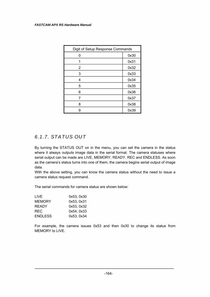
FASTCAM-APX RS Hardware Manual
-164-
Digit of Setup Response Commands
0 0x30 1 0x31 2 0x32 3 0x33 4 0x34 5 0x35 6 0x36 7 0x37 8 0x38 9 0x39
6.1.7. STATUS OUT By turning the STATUS OUT on in the menu, you can set the camera in the status where it always outputs image data in the serial format. The camera statuses where serial output can be made are LIVE, MEMORY, READY, REC and ENDLESS. As soon as the camera’s status turns into one of them, the camera begins serial output of image data. With the above setting, you can know the camera status without the need to issue a camera status request command. The serial commands for camera status are shown below: LIVE 0x53, 0x30 MEMORY 0x53, 0x31 READY 0x53, 0x32 REC 0x54, 0x33 ENDLESS 0x53, 0x34 For example, the camera issues 0x53 and then 0x30 to change its status from MEMORY to LIVE.
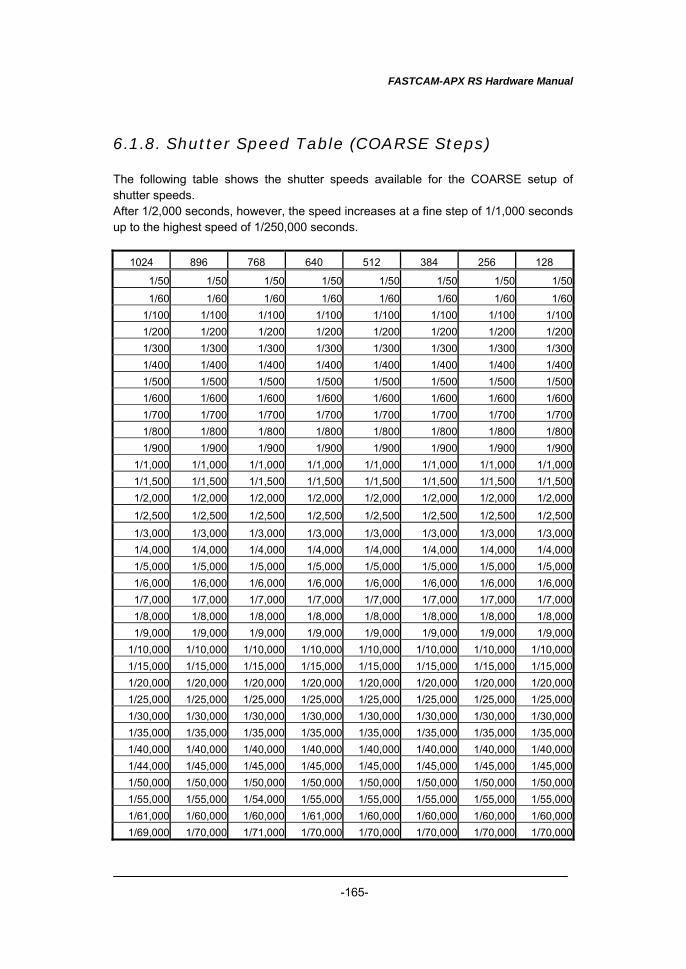
FASTCAM-APX RS Hardware Manual
-165-
6.1.8. Shutter Speed Table (COARSE Steps) The following table shows the shutter speeds available for the COARSE setup of shutter speeds. After 1/2,000 seconds, however, the speed increases at a fine step of 1/1,000 seconds up to the highest speed of 1/250,000 seconds.
1024 896 768 640 512 384 256 128
1/50 1/50 1/50 1/50 1/50 1/50 1/50 1/501/60 1/60 1/60 1/60 1/60 1/60 1/60 1/60
1/100 1/100 1/100 1/100 1/100 1/100 1/100 1/1001/200 1/200 1/200 1/200 1/200 1/200 1/200 1/2001/300 1/300 1/300 1/300 1/300 1/300 1/300 1/3001/400 1/400 1/400 1/400 1/400 1/400 1/400 1/4001/500 1/500 1/500 1/500 1/500 1/500 1/500 1/5001/600 1/600 1/600 1/600 1/600 1/600 1/600 1/6001/700 1/700 1/700 1/700 1/700 1/700 1/700 1/7001/800 1/800 1/800 1/800 1/800 1/800 1/800 1/8001/900 1/900 1/900 1/900 1/900 1/900 1/900 1/900
1/1,000 1/1,000 1/1,000 1/1,000 1/1,000 1/1,000 1/1,000 1/1,0001/1,500 1/1,500 1/1,500 1/1,500 1/1,500 1/1,500 1/1,500 1/1,5001/2,000 1/2,000 1/2,000 1/2,000 1/2,000 1/2,000 1/2,000 1/2,000
1/2,500 1/2,500 1/2,500 1/2,500 1/2,500 1/2,500 1/2,500 1/2,5001/3,000 1/3,000 1/3,000 1/3,000 1/3,000 1/3,000 1/3,000 1/3,0001/4,000 1/4,000 1/4,000 1/4,000 1/4,000 1/4,000 1/4,000 1/4,0001/5,000 1/5,000 1/5,000 1/5,000 1/5,000 1/5,000 1/5,000 1/5,0001/6,000 1/6,000 1/6,000 1/6,000 1/6,000 1/6,000 1/6,000 1/6,0001/7,000 1/7,000 1/7,000 1/7,000 1/7,000 1/7,000 1/7,000 1/7,0001/8,000 1/8,000 1/8,000 1/8,000 1/8,000 1/8,000 1/8,000 1/8,0001/9,000 1/9,000 1/9,000 1/9,000 1/9,000 1/9,000 1/9,000 1/9,000
1/10,000 1/10,000 1/10,000 1/10,000 1/10,000 1/10,000 1/10,000 1/10,0001/15,000 1/15,000 1/15,000 1/15,000 1/15,000 1/15,000 1/15,000 1/15,0001/20,000 1/20,000 1/20,000 1/20,000 1/20,000 1/20,000 1/20,000 1/20,0001/25,000 1/25,000 1/25,000 1/25,000 1/25,000 1/25,000 1/25,000 1/25,0001/30,000 1/30,000 1/30,000 1/30,000 1/30,000 1/30,000 1/30,000 1/30,0001/35,000 1/35,000 1/35,000 1/35,000 1/35,000 1/35,000 1/35,000 1/35,0001/40,000 1/40,000 1/40,000 1/40,000 1/40,000 1/40,000 1/40,000 1/40,0001/44,000 1/45,000 1/45,000 1/45,000 1/45,000 1/45,000 1/45,000 1/45,0001/50,000 1/50,000 1/50,000 1/50,000 1/50,000 1/50,000 1/50,000 1/50,0001/55,000 1/55,000 1/54,000 1/55,000 1/55,000 1/55,000 1/55,000 1/55,0001/61,000 1/60,000 1/60,000 1/61,000 1/60,000 1/60,000 1/60,000 1/60,0001/69,000 1/70,000 1/71,000 1/70,000 1/70,000 1/70,000 1/70,000 1/70,000
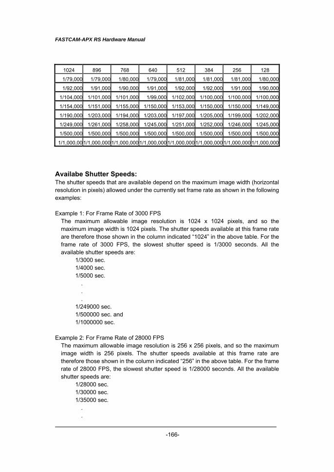
FASTCAM-APX RS Hardware Manual
-166-
1024 896 768 640 512 384 256 128
1/79,000 1/79,000 1/80,000 1/79,000 1/81,000 1/81,000 1/81,000 1/80,000
1/92,000 1/91,000 1/90,000 1/91,000 1/92,000 1/92,000 1/91,000 1/90,000
1/104,000 1/101,000 1/101,000 1/99,000 1/102,000 1/100,000 1/100,000 1/100,000
1/154,000 1/151,000 1/155,000 1/150,000 1/153,000 1/150,000 1/150,000 1/149,000
1/190,000 1/203,000 1/194,000 1/203,000 1/197,000 1/205,000 1/199,000 1/202,000
1/249,000 1/261,000 1/258,000 1/245,000 1/251,000 1/252,000 1/246,000 1/245,000
1/500,000 1/500,000 1/500,000 1/500,000 1/500,000 1/500,000 1/500,000 1/500,000
1/1,000,00 1/1,000,0001/1,000,000 1/1,000,0001/1,000,000 1/1,000,000 1/1,000,0001/1,000,000
Availabe Shutter Speeds: The shutter speeds that are available depend on the maximum image width (horizontal resolution in pixels) allowed under the currently set frame rate as shown in the following examples: Example 1: For Frame Rate of 3000 FPS
The maximum allowable image resolution is 1024 x 1024 pixels, and so the maximum image width is 1024 pixels. The shutter speeds available at this frame rate are therefore those shown in the column indicated “1024” in the above table. For the frame rate of 3000 FPS, the slowest shutter speed is 1/3000 seconds. All the available shutter speeds are:
1/3000 sec. 1/4000 sec. 1/5000 sec. . . . 1/249000 sec. 1/500000 sec. and 1/1000000 sec.
Example 2: For Frame Rate of 28000 FPS
The maximum allowable image resolution is 256 x 256 pixels, and so the maximum image width is 256 pixels. The shutter speeds available at this frame rate are therefore those shown in the column indicated “256” in the above table. For the frame rate of 28000 FPS, the slowest shutter speed is 1/28000 seconds. All the available shutter speeds are:
1/28000 sec. 1/30000 sec. 1/35000 sec. . .
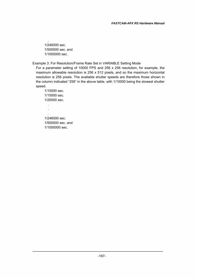
FASTCAM-APX RS Hardware Manual
-167-
. 1/246000 sec. 1/500000 sec. and 1/1000000 sec.
Example 3: For Resolution/Frame Rate Set in VARIABLE Setting Mode
For a parameter setting of 10000 FPS and 256 x 256 resolution, for example, the maximum allowable resolution is 256 x 512 pixels, and so the maximum horizontal resolution is 256 pixels. The available shutter speeds are therefore those shown in the column indicated “256” in the above table, with 1/10000 being the slowest shutter speed.
1/10000 sec. 1/15000 sec. 1/20000 sec. . . . 1/246000 sec. 1/500000 sec. and 1/1000000 sec.
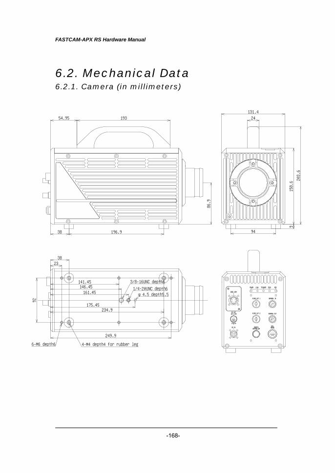
FASTCAM-APX RS Hardware Manual
-168-
6.2. Mechanical Data 6.2.1. Camera (in millimeters)
158.6 203.6
9
131.424
94
86.9
19354.95
196.938
IEEE 1394
DC IN
MJ -19
12V 0.8ADC OUT
RECIRIGTRIGGERLINKPOWER
MCDLRS422
GENERAL OUT
GENERAL IN
VIDEO OUT 2
VIDEO OUT 1
REMOTECONTROLLER
92
2338
141.45146.45161.45
175.45234.9
249.9
φ4.5 depth5.51/4-20UNC depth6
3/8-16UNC depth6
6-M6 depth6 4-M4 depth4 for rubber leg
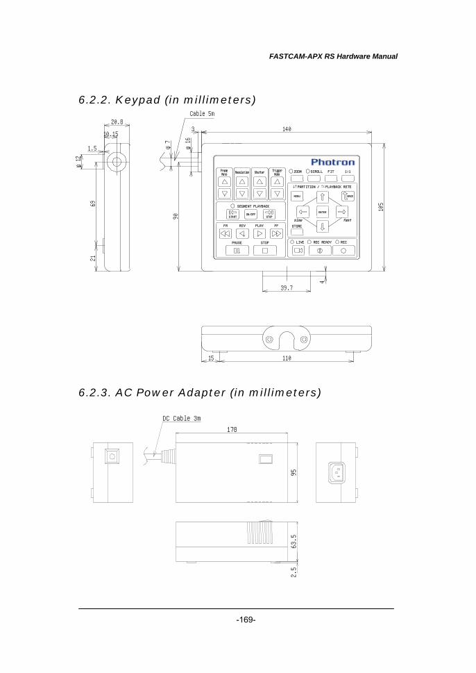
FASTCAM-APX RS Hardware Manual
-169-
6.2.2. Keypad (in millimeters)
6.2.3. AC Power Adapter (in millimeters)
178
9563.5
2.5
DC Cable 3m
REC READY RECLIVE
fastslow
BACK
SEGMENT PLAYBACK
ON/OFFSTOPSTART
ENTER
SCROLLZOOM 1:1FIT
PARTITION / PLAYBACK RETE
MENU
STORE
TriggerMode
FrameRate
ShutterResolution
FFPLAYREVFR
STOPPAUSE
140
105
4
90
6921
10.15
20.8
1.5
11015
39.7
φ16
3
φ7
φ12
Cable 5m
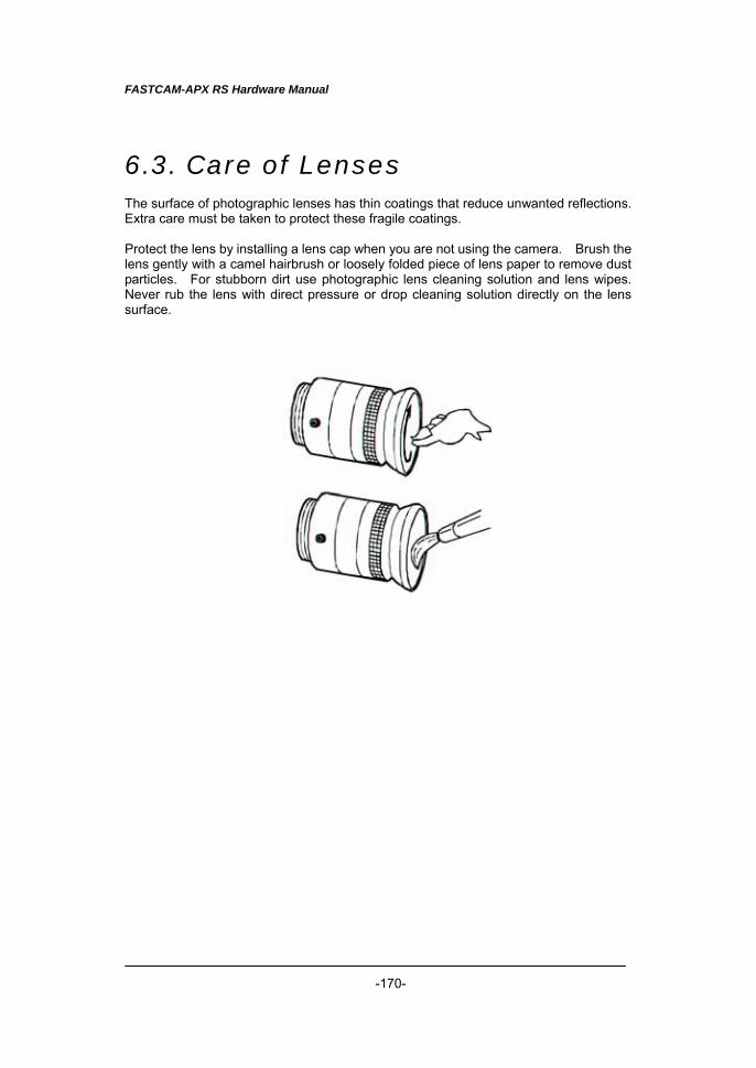
FASTCAM-APX RS Hardware Manual
-170-
6.3. Care of Lenses The surface of photographic lenses has thin coatings that reduce unwanted reflections. Extra care must be taken to protect these fragile coatings. Protect the lens by installing a lens cap when you are not using the camera. Brush the lens gently with a camel hairbrush or loosely folded piece of lens paper to remove dust particles. For stubborn dirt use photographic lens cleaning solution and lens wipes. Never rub the lens with direct pressure or drop cleaning solution directly on the lens surface.
In Americas and Antipodes: PHOTRON USA, INC.
9520 Padgett Street, Suite 110 San Diego, CA 92126-4446, USA
Phone: 858-684-3555 Fax: 858-684-3558
E-mail: [email protected] www.photron.com
In Europe, Africa and India:
PHOTRON EUROPE LIMITED Willowbank House
84 Station Road Marlow, Bucks SL7 1NK, U.K. Phone: +44(0) 1628 89 4353 Fax: +44(0) 1628 89 4354
E-mail: [email protected] www.photron.com
In other areas:
PHOTRON LIMITED Fujimi 1-1-8, Chiyoda-Ku Tokyo 102-0071, Japan
Phone: +81 3 3238 2170 Fax: +81 3 3238 2134
E-mail: [email protected] www.photron.co.jp
FASTCAM-APX RS Hardware Manual
English Version 2006/5
Rev.1.05
Related Documents