Experiments in Fixed-Wing UAV Perching Rick Cory * and Russ Tedrake † MIT Computer Science and Artificial Intelligence Lab, Cambridge, MA, 02139, USA High-precision maneuvers at high angles-of-attack are not properly addressed by even the most advanced aircraft control systems. Here we present our control design procedure and indoor experimental results with a small fixed-wing autonomous glider which is capable of executing an aggressive high angle-of-attack maneuver in order to land on a perch. We first acquire a surprisingly accurate aircraft model through unsteady flight regimes from real kinematic flight data taken in a motion-capture arena. This model is then used in a numerical nonlinear (approximate) optimal control procedure which designs a feedback control policy for the elevator deflection. Finally, we report our experimental data demon- strating that this simple glider can exploit pressure drag to achieve a high-speed perching maneuver. Nomenclature x Horizontal position, m z Vertical position, m θ Pitch angle of fuselage and wing, in the lab frame, radians ψ Elevator deflection angle, in the fuselage frame, relative to trim, radians x Full state vector, x =[x, z, θ, ψ, ˙ x, ˙ z, ˙ θ, ˙ ψ] T , u Elevator command, ∈ [-1, 1] α Angle-of-attack of the wing F Force, N M Moment, Nm w Coefficient model parameters v Coefficient model nonlinear feature c Mean aerodynamic chord π Feedback policy J Cost-to-go function Q Symmetric positive-definite quadratic penalty matrix Subscript i Variable number L Lift D Drag Superscript d Desired value * Optimal (as in π * or J * ) I. Introduction Birds routinely execute aerial maneuvers that are still well beyond the capabilities of our best aircraft control systems. During a perching maneuver, birds often exceed 90 degrees in angle-of-attack, exploiting both viscous and pressure drag for rapid deceleration. Despite the complexity of the fluid dynamics in these unsteady regimes, the inevitable loss of control authority on the wings as the velocity of the bird reaches zero, * Ph.D. Candidate, Electrical Engineering and Computer Science, [email protected]. † Assistant Professor, Electrical Engineering and Computer Science, [email protected], Member AIAA. 1 of 12 American Institute of Aeronautics and Astronautics

Welcome message from author
This document is posted to help you gain knowledge. Please leave a comment to let me know what you think about it! Share it to your friends and learn new things together.
Transcript
Experiments in Fixed-Wing UAV Perching
Rick Cory∗ and Russ Tedrake†
MIT Computer Science and Artificial Intelligence Lab, Cambridge, MA, 02139, USA
High-precision maneuvers at high angles-of-attack are not properly addressed by eventhe most advanced aircraft control systems. Here we present our control design procedureand indoor experimental results with a small fixed-wing autonomous glider which is capableof executing an aggressive high angle-of-attack maneuver in order to land on a perch. Wefirst acquire a surprisingly accurate aircraft model through unsteady flight regimes fromreal kinematic flight data taken in a motion-capture arena. This model is then used ina numerical nonlinear (approximate) optimal control procedure which designs a feedbackcontrol policy for the elevator deflection. Finally, we report our experimental data demon-strating that this simple glider can exploit pressure drag to achieve a high-speed perchingmaneuver.
Nomenclature
x Horizontal position, mz Vertical position, mθ Pitch angle of fuselage and wing, in the lab frame, radiansψ Elevator deflection angle, in the fuselage frame, relative to trim, radiansx Full state vector, x = [x, z, θ, ψ, x, z, θ, ψ]T ,u Elevator command, ∈ [−1, 1]α Angle-of-attack of the wingF Force, NM Moment, Nmw Coefficient model parametersv Coefficient model nonlinear featurec Mean aerodynamic chordπ Feedback policyJ Cost-to-go functionQ Symmetric positive-definite quadratic penalty matrixSubscripti Variable numberL LiftD DragSuperscriptd Desired value∗ Optimal (as in π∗ or J∗)
I. Introduction
Birds routinely execute aerial maneuvers that are still well beyond the capabilities of our best aircraftcontrol systems. During a perching maneuver, birds often exceed 90 degrees in angle-of-attack, exploitingboth viscous and pressure drag for rapid deceleration. Despite the complexity of the fluid dynamics in theseunsteady regimes, the inevitable loss of control authority on the wings as the velocity of the bird reaches zero,∗Ph.D. Candidate, Electrical Engineering and Computer Science, [email protected].†Assistant Professor, Electrical Engineering and Computer Science, [email protected], Member AIAA.
1 of 12
American Institute of Aeronautics and Astronautics
and a stochastic, partially-observable aerodynamic environment including wind gusts (which effect both thebird and the perch), birds are remarkably adept at accomplishing this high-precision task.
Perching, one of the most common aerobatic maneuvers executed by birds, is representative of a largeand important class of aggressive aerial maneuvers that take advantage of unsteady aerodynamics. Perchingwith a fixed-wing unmanned aerial vehicle (UAV) represents a formidable challenge for nonlinear controls.Following,1 we distinguish a dynamic perching maneuver from V/STOL maneuvers by the use of a separation-induced pressure drag to decelerate the vehicle. Executing these dynamic maneuvers allows birds to perch inmuch less time and with much less energy (scaled) than man-made V/STOL equivalents. A lack of compact,design-accessible models in this flow regime (with chord Reynolds numbers exceeding 15,000) hinders the useof traditional control design techniques. However, recent advances from the machine learning community mayoffer a solution. Statistical learning theory provides new opportunities for unsteady system identification, andstatistical approaches to approximate optimal control provide practical algorithms for developing feedbackcontrollers. In this paper we present our intial experiments using these techniques, which have allowed us todevelop a controller capable of perching a fixed-wing glider in an indoor motion capture environment.
II. Related Work
The most notable project which shares our goals is the perching plane project at Cornell.1–3 The aim ofthis project is to design a morphing aircraft which pitches the body up to a high angle-of-attack but rotatesthe wings back down into the traditional envelope of attached airflow. Similarly, the tail is rotated downand out of the unsteady wake of the body in order to ensure attached flow. This is a clever mechanismfor maintaining control authority, but requires a redesign of the vehicle and sacrifices performance (only aportion of the vehicle contributes to pressure drag) in order to allow the use of linear flight control techniques.Our approach is different. He we describe the design of a nonlinear flight control system capable of executingthe maneuver with a more conventional vehicle, exploiting pressure drag on the body and the wings.
There have also been numerous studies on control systems for UAV acrobatics. For example, the workpresented in4 proposed an approximate inverse dynamics model for agile maneuvering where the resultantcontrol system was tested in simulation. However, the maneuver performed was slow and well behaved,not representative of human piloted maneuvers that take the vehicle to the perimeter of its flight envelope.Work in5–9 all propose a linear control system for performing an autonomous prop-hang, where a fixed-wingvehicle is oriented vertically (i.e. nose up) maintaining close to zero translational velocity. These maneuvers,although impressive demonstrations, all rely on tremendous thrust-to-weight ratios (and therefore sacrificeefficiency) to dominate the dynamics of the air at high angles-of-attack.
The most notable work in autonomous UAV acrobatics has been on helicopters. Feron et al. were one ofthe first to achieve autonomous acrobatic flight with a hobby helicopter10 . In this work an analytical dynamicmodel was derived from basic principles and force coefficients were measured through flight experiments.Their control system used an intuitive control approach where state machines were developed based on humanpilot control data. Through use of piecewise linear commands with specified switching times, the authorswere able to perform various maneuvers. Feron’s subsequent work added feedback through tight angularrate controllers on the pilot’s reference trajectory.15,16 Feron et al17 also present a control architecture forhelicopters landing at unusual attitudes. In this work they use a hand designed state-machine to execute aperching maneuver that eventually lands on a large velcro launch pad.
There is also some precedent for the application of machine learning control technology to aerial acrobat-ics. Work by Bagnell18 describes a unique approach to helicopter control, namely a computational optimalcontrol method, similar to the method described in this paper, known as reinforcement learning. The authorspresented a control policy search algorithm for stabilizing slow moving trajectories. Later work by Ng etal.19–22 used a similar approach for acrobatic helicopter control. The authors first fit a stochastic nonlinearmodel from pilot data, i.e. a model predicting either next state or accelerations as a function of currentstate and control inputs. Next, a human pilot flight trajectory for a desired acrobatic maneuver was used asthe baseline for an offline control policy search algorithm. Using this approach, an autonomous helicopterachieved stable inverted hover in addition to a few acrobatic maneuvers at slow speeds. We note that (withthe exception of inverted hovering) Ng’s and Feron’s acrobatic control systems focused on stabilizing eithera human pilot’s trajectories or a state machine inspired by these trajectories.
2 of 12
American Institute of Aeronautics and Astronautics
III. Task Formulation
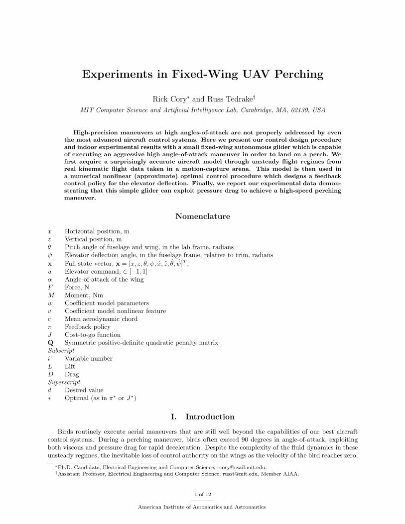
In this paper we consider the task of making a small autonomously controlled glider land on a laboratoryperch. Our focus on a glider (no onboard power plant) helps to emphasize the dynamics of the task and avoidscontrol solutions which exploit the large thrust-to-weight ratios available on some small hobby aircraft. Thesethrust-to-weight ratios are energetically expensive to maintain, and are not necessary for high-performanceperching.
Figure 1. The perching task. This trajectory of the glider illustrated here is actually derived from real flight data of asuccessful perch.
Specifically, we launch a small 77 g glider with a 98mm mean chord and a 8:3 aspect ratio out ofa small custom launching device towards a suspended string perch. The vehicle enters our experimentalsetup at approximately 6 m/s (Re ≈ 53, 000), and about 3.5 m away from the perch. The vehicle mustdecelerate to almost zero velocity and come to rest on the perch in less than one second. We claim that, withthese specifications, the glider must execute a high angle-of-attack maneuver, exploiting both viscous andpressure drag to achieve the required rapid deceleration. Despite the obvious nonlinearity and complexityof this dynamic regime and the short-term loss of control authority on the stalled control surfaces, the taskrequirements demand a high-precision landing on the string. Figure 1 shows a feasible perching trajectory.Note the initial dip in altitude, which compensates for the boost in altitude right before stalling the wingsat the end of the trajectory.
IV. Experimental Setup
IV.A. Offboard Sensing and Control
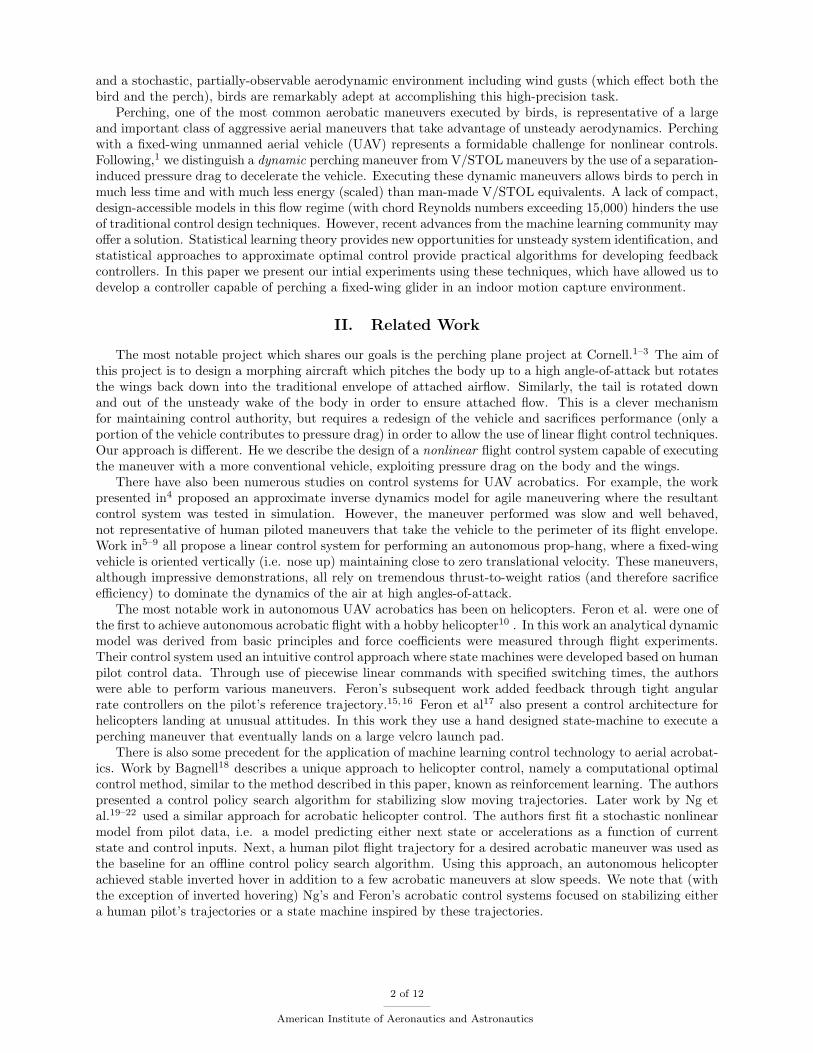
For this pilot study, we have designed an indoor experimental facility which mitigates many of the complica-tions of sensing, computation, and repeatability. Our facility is equipped with a Vicon MX motion capturesystem consisting of 16 cameras, which use infrared light to track reflective markers on the vehicle. Thesystem provides real-time sub-millimeter tracking of the vehicle and its control surface deflections, as well asthe perch location. The basic setup is illustrated in Figure 2. Our system has a capture volume of approxi-mately 27 m3 with the real-time hardware interface communicating new state information at approximately119 frames per second. To protect the vehicle, we hang a large safety net just above the floor under theentire experiment.
The only sensing equipment onboard the vehicle is a set of small reflective markers attached to thefuselage and elevator. The glider is launched from just outside the capture volume of the Vicon system.Upon entering the volume, the real-time tracking software locks onto the plane and begins relaying positionand orientation information over ethernet to the ground control station, a Linux PC running Matlab. Theground control station evaluates the control policy at 50 Hz and sends a command by serial port to thebuddy-box interface of a hobby radio transmitter.
This indoor flight environment providing off-board sensing, computation, and control has proven to be anextremely effective experimental paradigm. The protective environment for the vehicle allows us to exploremaneuvers well outside the typical flight regime with little risk of damaging the vehicle, and as we reportin the following sections, the flight data attained from the motion capture system provides incredibly cleandata for system identification.
IV.B. Vehicle Description
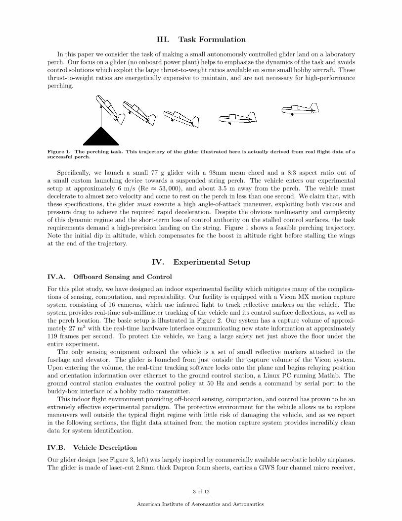
Our glider design (see Figure 3, left) was largely inspired by commercially available aerobatic hobby airplanes.The glider is made of laser-cut 2.8mm thick Dapron foam sheets, carries a GWS four channel micro receiver,
3 of 12
American Institute of Aeronautics and Astronautics
Figure 2. Vicon Motion Capture Environment. The Vicon motion capture setup makes use of 16 infrared camerasto track small reflective markers along the body and control surface of the glider. These marker positions allow thesystem to reconstruct the position and orientation of the glider and the control surfaces with high accuracy.
Figure 3. (left) Our experimental glider with a 20◦ dihedral on the wings for passive lateral stability. Reflective markersare placed along the body and the elevator in order to reconstruct absolute position and orientation using the Viconmotion capture system. (right) Electronics and components: (clockwise from top) hobby servo, motion capture marker,battery, micro receiver. (Quarter shown for scale).
an HS-55 Hitech hobby servo, and a Full River 250mah 2-cell lithium polymer battery (see Figure 3, right),giving a total combined weight of 77g. For ease of fabrication, the wings are a symmetric foam flat plate (i.e.no camber) with a carbon fiber reinforced leading edge having a 98mm mean chord (≈ 3% thickness-to-chordratio), a 8:3 aspect ratio, with a maximum lift to drag ratio of approximately 3.5 (at zero elevator angle).The wings are slightly tapered (113mm root chord, 83mm tip chord), and have a 20◦ dihedral for passivelateral stability. The total surface area of all lifting surfaces (including the fuselage) is 0.1022m2 for a totalwing/surface loading of 0.7534 kg
m2 . Four 10mm reflective markers placed along the fuselage and four on theelevator control surface allow motion capture reconstruction. The vehicle grabs the perch with a passivemechanical one-way latch mounted just below the center of mass, with a capture window of ¡ 2cm.
The most basic trajectory of a glider landing on a perch can be sufficiently described by the glider’slongitudinal dynamics. During this maneuver, these dynamics are mostly controlled by the elevator (con-trolling pitch) and minor corrections must be made by the ailerons and rudder for deviations outside thelongitudinal plane, i.e. roll and yaw. However, given that our glider is unpropelled during flight, the extradrag induced by these control surface deflections creates a non-negligible loss in speed early in the glider’strajectory. A fixed vertical stabilizer and our wing dihedral produce similar lateral corrective forces withoutthe added aerodynamic drag.
4 of 12
American Institute of Aeronautics and Astronautics
V. Unsteady System Identification
V.A. The Flight Data
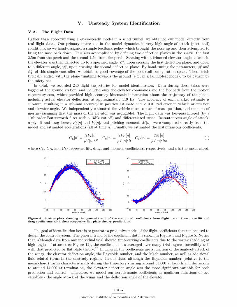
Rather than approximating a quasi-steady model in a wind tunnel, we obtained our model directly fromreal flight data. Our primary interest is in the model dynamics in very high angle-of-attack (post-stall)conditions, so we hand-designed a simple feedback policy which brought the nose up and then attempted tobring the nose back down. This was accomplished by defining two deflection planes in the x-axis, the first2.5m from the perch and the second 1.5m from the perch. Starting with a trimmed elevator angle at launch,the elevator was then deflected up to a specified angle, ψd1 , upon crossing the first deflection plane, and downto a different angle, ψd2 , upon crossing the second deflection plane. By hand-tuning the parameters, ψd1 andψd2 , of this simple controller, we obtained good coverage of the post-stall configuration space. These trialstypically ended with the plane tumbling towards the ground (e.g., in a falling-leaf mode), to be caught bythe safety net.
In total, we recorded 240 flight trajectories for model identification. Data during these trials werelogged at the ground station, and included only the elevator commands and the feedback from the motioncapture system, which provided high-accuracy kinematic information about the trajectory of the plane,including actual elevator deflection, at approximately 119 Hz. The accuracy of each marker estimate issub-mm, resulting in a sub-mm accuracy in position estimate and < 0.01 rad error in vehicle orientationand elevator angle. We independently estimated the vehicle mass, center of mass position, and moment ofinertia (assuming that the mass of the elevator was negligible). The flight data was low-pass filtered (by a10th order Butterworth filter with a 15Hz cut-off) and differentiated twice. Instantaneous angle-of-attack,α[n], lift and drag forces, FL[n] and Fd[n], and pitching moment, M [n], were computed directly from themodel and estimated accelerations (all at time n). Finally, we estimated the instantaneous coefficients,
CL[n] =2FL[n]ρV [n]2S
CD[n] =2FD[n]ρV [n]2S
CM [n] =2M [n]ρV [n]2Sc
, (1)
where CL, CD, and CM represent lift, drag, and moment coefficients, respectively, and c is the mean chord.
−20 0 20 40 60 80 100 120 140 160−1.5
−1
−0.5
0
0.5
1
1.5
Angle of Attack
Cl
Glider DataFlat Plate Theory
−20 0 20 40 60 80 100 120 140 160−0.5
0
0.5
1
1.5
2
2.5
3
3.5
Angle of Attack
Cd
Glider DataFlat Plate Theory
Figure 4. Scatter plots showing the general trend of the computed coefficients from flight data. Shown are lift anddrag coefficients with their respective flat plate theory predictions.
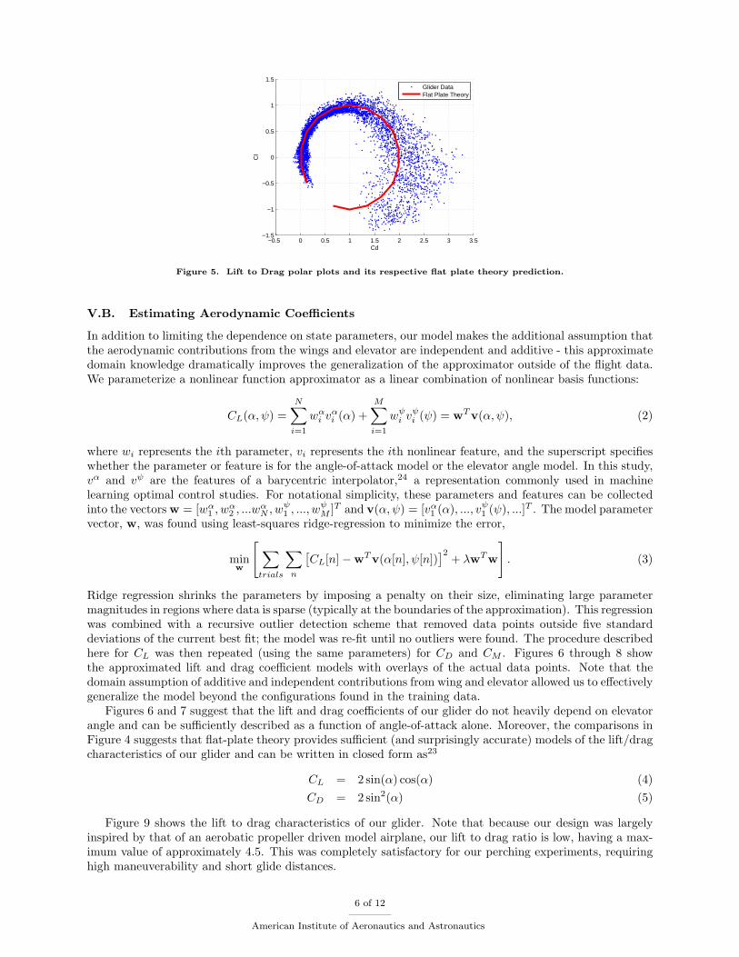
The goal of identification here is to generate a predictive model of the flight coefficients that can be used todesign the control system. The general trend of the coefficient data is shown in Figure 4 and Figure 5. Noticethat, although data from any individual trial showed time-varying coefficients due to the vortex shedding athigh angles of attack (see Figure 12), the coefficient data averaged over many trials agrees incredibly wellwith that predicted by flat plate theory.23 In general, the coefficients are a function of the angle-of-attack ofthe wings, the elevator deflection angle, the Reynolds number, and the Mach number, as well as additionalfluid-related terms in the unsteady regime. In our data, although the Reynolds number (relative to themean chord) varies characteristically during the trajectory starting around 53,000 at launch and decreasingto around 14,000 at termination, the elevator deflection angle was the more significant variable for bothprediction and control. Therefore, we model our aerodynamic coefficients as nonlinear functions of twovariables - the angle attack of the wings and the deflection angle of the elevator.
5 of 12
American Institute of Aeronautics and Astronautics
−0.5 0 0.5 1 1.5 2 2.5 3 3.5−1.5
−1
−0.5
0
0.5
1
1.5
CdC
l
Glider DataFlat Plate Theory
Figure 5. Lift to Drag polar plots and its respective flat plate theory prediction.
V.B. Estimating Aerodynamic Coefficients
In addition to limiting the dependence on state parameters, our model makes the additional assumption thatthe aerodynamic contributions from the wings and elevator are independent and additive - this approximatedomain knowledge dramatically improves the generalization of the approximator outside of the flight data.We parameterize a nonlinear function approximator as a linear combination of nonlinear basis functions:
CL(α,ψ) =N∑i=1
wαi vαi (α) +
M∑i=1
wψi vψi (ψ) = wTv(α,ψ), (2)
where wi represents the ith parameter, vi represents the ith nonlinear feature, and the superscript specifieswhether the parameter or feature is for the angle-of-attack model or the elevator angle model. In this study,vα and vψ are the features of a barycentric interpolator,24 a representation commonly used in machinelearning optimal control studies. For notational simplicity, these parameters and features can be collectedinto the vectors w = [wα1 , w
α2 , ...w
αN , w
ψ1 , ..., w
ψM ]T and v(α,ψ) = [vα1 (α), ..., vψ1 (ψ), ...]T . The model parameter
vector, w, was found using least-squares ridge-regression to minimize the error,
minw
[∑trials
∑n
[CL[n]−wTv(α[n], ψ[n])
]2+ λwTw
]. (3)
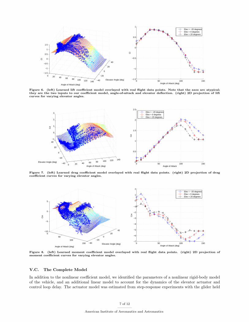
Ridge regression shrinks the parameters by imposing a penalty on their size, eliminating large parametermagnitudes in regions where data is sparse (typically at the boundaries of the approximation). This regressionwas combined with a recursive outlier detection scheme that removed data points outside five standarddeviations of the current best fit; the model was re-fit until no outliers were found. The procedure describedhere for CL was then repeated (using the same parameters) for CD and CM . Figures 6 through 8 showthe approximated lift and drag coefficient models with overlays of the actual data points. Note that thedomain assumption of additive and independent contributions from wing and elevator allowed us to effectivelygeneralize the model beyond the configurations found in the training data.
Figures 6 and 7 suggest that the lift and drag coefficients of our glider do not heavily depend on elevatorangle and can be sufficiently described as a function of angle-of-attack alone. Moreover, the comparisons inFigure 4 suggests that flat-plate theory provides sufficient (and surprisingly accurate) models of the lift/dragcharacteristics of our glider and can be written in closed form as23
CL = 2 sin(α) cos(α) (4)CD = 2 sin2(α) (5)
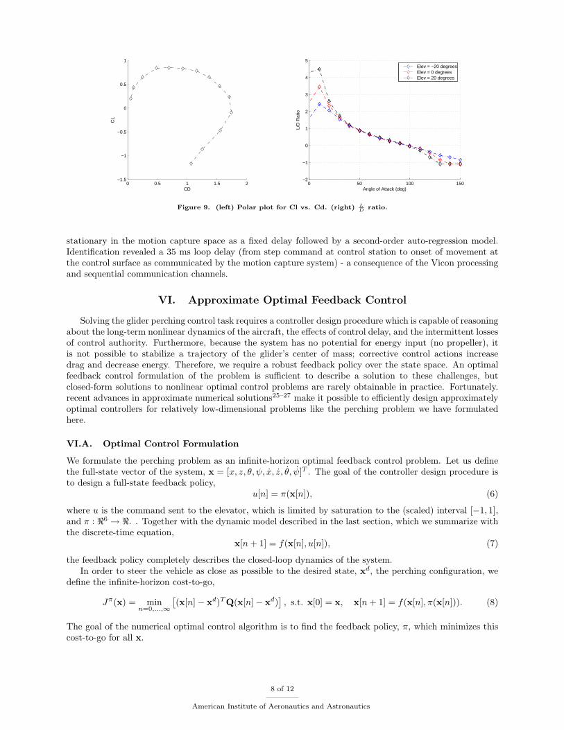
Figure 9 shows the lift to drag characteristics of our glider. Note that because our design was largelyinspired by that of an aerobatic propeller driven model airplane, our lift to drag ratio is low, having a max-imum value of approximately 4.5. This was completely satisfactory for our perching experiments, requiringhigh maneuverability and short glide distances.
6 of 12
American Institute of Aeronautics and Astronautics
0 20 40 60 80 100 120 140 −40
−20
0
20
40
−1.5
−1
−0.5
0
0.5
1
1.5
Elevator Angle (deg)
Angle of Attack (deg)
Cl
0 50 100 150−1.5
−1
−0.5
0
0.5
1
Angle of Attack (deg)
Cl
Elev = −20 degreesElev = 0 degreesElev = 20 degrees
Figure 6. (left) Learned lift coefficient model overlayed with real flight data points. Note that the axes are atypical;they are the two inputs to our coefficient model, angle-of-attack and elevator deflection. (right) 2D projection of liftcurves for varying elevator angles.
0 20 40 60 80 100 120 140
−40
−20
0
20
40−1
0
1
2
3
Angle of Attack (deg)
Elevator Angle (deg)
Cd
0 50 100 1500
0.5
1
1.5
2
2.5
Angle of Attack
Cd
Elev = −20 degreesElev = 0 degreesElev = 20 degrees
Figure 7. (left) Learned drag coefficient model overlayed with real flight data points. (right) 2D projection of dragcoefficient curves for varying elevator angles.
0
50
100
150 −40
−20
0
20
40−10
−5
0
5
Elevator Angle (deg)Angle of Attack (deg)
Cm
0 50 100 150−7
−6
−5
−4
−3
−2
−1
0
1
2
Angle of Attack (deg)
Cm
Elev = −20 degreesElev = 0 degreesElev = 20 degrees
Figure 8. (left) Learned moment coefficient model overlayed with real flight data points. (right) 2D projection ofmoment coefficient curves for varying elevator angles.
V.C. The Complete Model
In addition to the nonlinear coefficient model, we identified the parameters of a nonlinear rigid-body modelof the vehicle, and an additional linear model to account for the dynamics of the elevator actuator andcontrol loop delay. The actuator model was estimated from step-response experiments with the glider held
7 of 12
American Institute of Aeronautics and Astronautics
0 0.5 1 1.5 2−1.5
−1
−0.5
0
0.5
1
CD
CL
0 50 100 150−2
−1
0
1
2
3
4
5
Angle of Attack (deg)
L/D
Rat
io
Elev = −20 degreesElev = 0 degreesElev = 20 degrees
Figure 9. (left) Polar plot for Cl vs. Cd. (right) LD ratio.
stationary in the motion capture space as a fixed delay followed by a second-order auto-regression model.Identification revealed a 35 ms loop delay (from step command at control station to onset of movement atthe control surface as communicated by the motion capture system) - a consequence of the Vicon processingand sequential communication channels.
VI. Approximate Optimal Feedback Control
Solving the glider perching control task requires a controller design procedure which is capable of reasoningabout the long-term nonlinear dynamics of the aircraft, the effects of control delay, and the intermittent lossesof control authority. Furthermore, because the system has no potential for energy input (no propeller), itis not possible to stabilize a trajectory of the glider’s center of mass; corrective control actions increasedrag and decrease energy. Therefore, we require a robust feedback policy over the state space. An optimalfeedback control formulation of the problem is sufficient to describe a solution to these challenges, butclosed-form solutions to nonlinear optimal control problems are rarely obtainable in practice. Fortunately.recent advances in approximate numerical solutions25–27 make it possible to efficiently design approximatelyoptimal controllers for relatively low-dimensional problems like the perching problem we have formulatedhere.
VI.A. Optimal Control Formulation
We formulate the perching problem as an infinite-horizon optimal feedback control problem. Let us definethe full-state vector of the system, x = [x, z, θ, ψ, x, z, θ, ψ]T . The goal of the controller design procedure isto design a full-state feedback policy,
u[n] = π(x[n]), (6)
where u is the command sent to the elevator, which is limited by saturation to the (scaled) interval [−1, 1],and π : <6 → <. . Together with the dynamic model described in the last section, which we summarize withthe discrete-time equation,
x[n+ 1] = f(x[n], u[n]), (7)
the feedback policy completely describes the closed-loop dynamics of the system.In order to steer the vehicle as close as possible to the desired state, xd, the perching configuration, we
define the infinite-horizon cost-to-go,
Jπ(x) = minn=0,...,∞
[(x[n]− xd)TQ(x[n]− xd)
], s.t. x[0] = x, x[n+ 1] = f(x[n], π(x[n])). (8)
The goal of the numerical optimal control algorithm is to find the feedback policy, π, which minimizes thiscost-to-go for all x.
8 of 12
American Institute of Aeronautics and Astronautics
VI.B. A Value Iteration Algorithm
The cost-to-go function described above does not have the standard additive cost structure which is so oftenexploited in optimal control algorithms.26 However, a solution to this cost function can be approximatedwith equally simple algorithms by noting the recurrence relation:
Jπ(x) = min[(x[n]− xd)TQ(x[n]− xd), Jπ(x′)
], x′ = f(x, π(x))). (9)
Note that the ‘min’ in this equation returns the minimum value of the two arguments. Similarly, the optimalpolicy, π∗ and optimal cost-to-go, J∗, subscribe to the relation:
J∗(x) = min[(x[n]− xd)TQ(x[n]− xd), J∗(x′)
], x′ = f(x, π∗(x))). (10)
By discretizing the state space, this relation provides a recursive algorithm which, for any initial guess J∗(x),will converge to the optimal solution J∗(x) of the discretized system. We perform this discretization, andthe interpolation back into a continuous full-state policy, using another barycentric function approximator.In order to be computationally tractable, the discretization in this high-dimensional space must be verycoarse; we use 15 bins on x and z, and 8 bins each on θ, x, z, and θ. We assume that the current state ofthe elevator, ψ and ψ, do not have a major impact on the optimal feedback policy.
VI.C. Coping With Delay
In fact, the dynamics of the system are not quite as ideal as described in the control derivation above.Recall that our linear actuator model also takes into account the feedback delay in the system. Naively, thisdelay will increase the number of state variables for our optimal control algorithm. However, we can takeadvantage of the structure of this pure delay, which happens to be 4 in our discrete-time model, by observingthat the delayed dynamics can be written as
x[n+ 1] = f(x[n], u[n− 4]). (11)
Therefore, if we solve the optimal control equations above, assuming no delay, we can (through a change ofvariables) write the optimal feedback policy as
u[n] = π∗(x[n+ 4]). (12)
Thanks to the high-fidelity of our model, we can execute this policy on the real plane by simulating our stateestimate forward in time:
x[n+ 4] = f4(x[n], u[n− 4], u[n− 3], u[n− 2], u[n− 1]), (13)
where f4 is the 4-step dynamics of f .
VI.D. Simulation Results
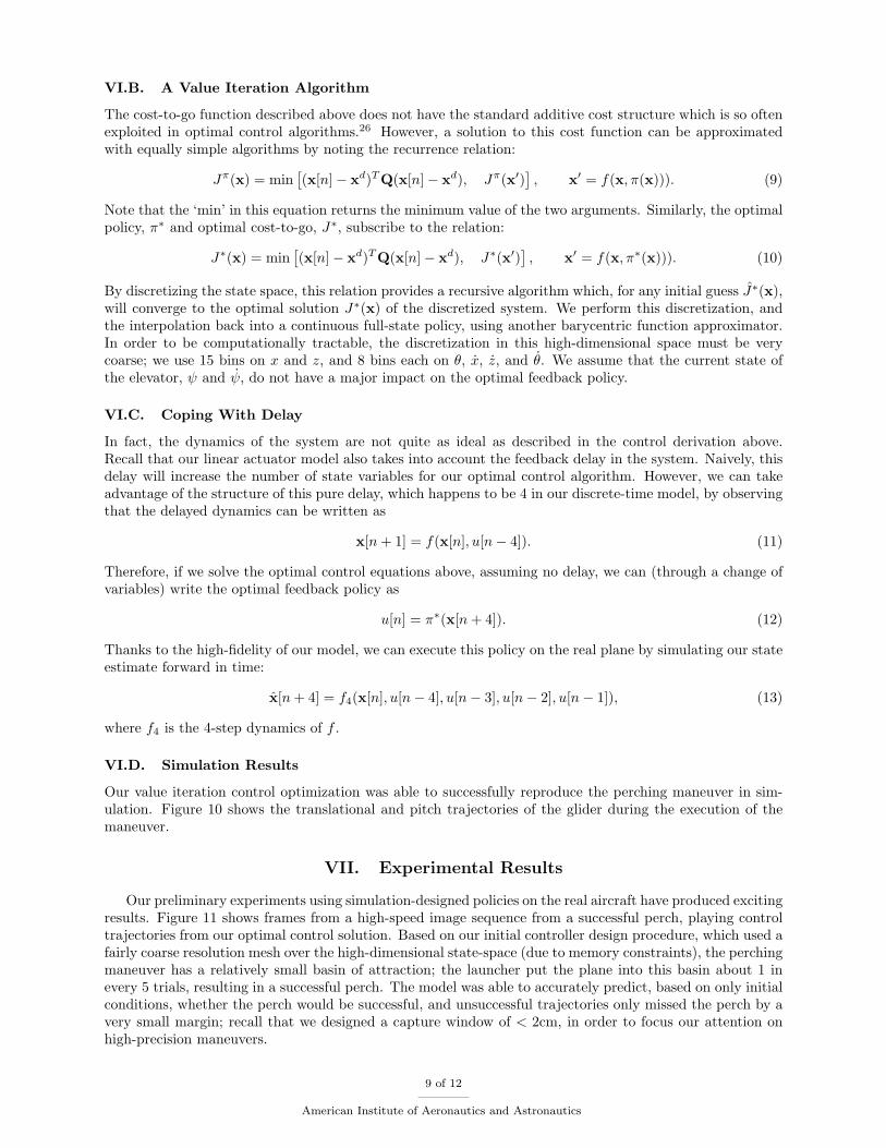
Our value iteration control optimization was able to successfully reproduce the perching maneuver in sim-ulation. Figure 10 shows the translational and pitch trajectories of the glider during the execution of themaneuver.
VII. Experimental Results
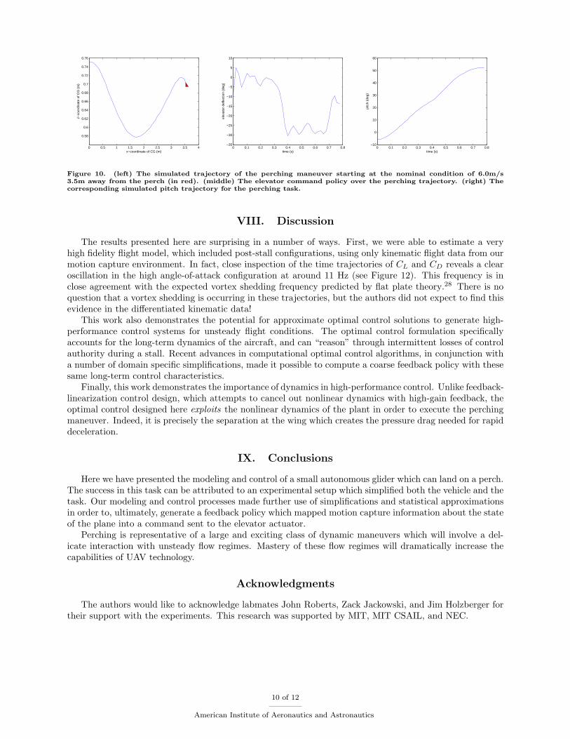
Our preliminary experiments using simulation-designed policies on the real aircraft have produced excitingresults. Figure 11 shows frames from a high-speed image sequence from a successful perch, playing controltrajectories from our optimal control solution. Based on our initial controller design procedure, which used afairly coarse resolution mesh over the high-dimensional state-space (due to memory constraints), the perchingmaneuver has a relatively small basin of attraction; the launcher put the plane into this basin about 1 inevery 5 trials, resulting in a successful perch. The model was able to accurately predict, based on only initialconditions, whether the perch would be successful, and unsuccessful trajectories only missed the perch by avery small margin; recall that we designed a capture window of < 2cm, in order to focus our attention onhigh-precision maneuvers.
9 of 12
American Institute of Aeronautics and Astronautics
0 0.5 1 1.5 2 2.5 3 3.5 4
0.58
0.6
0.62
0.64
0.66
0.68
0.7
0.72
0.74
0.76
x−coordinate of CG (m)
z−co
ordi
nate
of C
G (
m)
0 0.1 0.2 0.3 0.4 0.5 0.6 0.7 0.8−35
−30
−25
−20
−15
−10
−5
0
5
10
time (s)
elev
ator
def
lect
ion
(deg
)
0 0.1 0.2 0.3 0.4 0.5 0.6 0.7 0.8−10
0
10
20
30
40
50
60
time (s)
pitc
h (d
eg)
Figure 10. (left) The simulated trajectory of the perching maneuver starting at the nominal condition of 6.0m/s3.5m away from the perch (in red). (middle) The elevator command policy over the perching trajectory. (right) Thecorresponding simulated pitch trajectory for the perching task.
VIII. Discussion
The results presented here are surprising in a number of ways. First, we were able to estimate a veryhigh fidelity flight model, which included post-stall configurations, using only kinematic flight data from ourmotion capture environment. In fact, close inspection of the time trajectories of CL and CD reveals a clearoscillation in the high angle-of-attack configuration at around 11 Hz (see Figure 12). This frequency is inclose agreement with the expected vortex shedding frequency predicted by flat plate theory.28 There is noquestion that a vortex shedding is occurring in these trajectories, but the authors did not expect to find thisevidence in the differentiated kinematic data!
This work also demonstrates the potential for approximate optimal control solutions to generate high-performance control systems for unsteady flight conditions. The optimal control formulation specificallyaccounts for the long-term dynamics of the aircraft, and can “reason” through intermittent losses of controlauthority during a stall. Recent advances in computational optimal control algorithms, in conjunction witha number of domain specific simplifications, made it possible to compute a coarse feedback policy with thesesame long-term control characteristics.
Finally, this work demonstrates the importance of dynamics in high-performance control. Unlike feedback-linearization control design, which attempts to cancel out nonlinear dynamics with high-gain feedback, theoptimal control designed here exploits the nonlinear dynamics of the plant in order to execute the perchingmaneuver. Indeed, it is precisely the separation at the wing which creates the pressure drag needed for rapiddeceleration.
IX. Conclusions
Here we have presented the modeling and control of a small autonomous glider which can land on a perch.The success in this task can be attributed to an experimental setup which simplified both the vehicle and thetask. Our modeling and control processes made further use of simplifications and statistical approximationsin order to, ultimately, generate a feedback policy which mapped motion capture information about the stateof the plane into a command sent to the elevator actuator.
Perching is representative of a large and exciting class of dynamic maneuvers which will involve a del-icate interaction with unsteady flow regimes. Mastery of these flow regimes will dramatically increase thecapabilities of UAV technology.
Acknowledgments
The authors would like to acknowledge labmates John Roberts, Zack Jackowski, and Jim Holzberger fortheir support with the experiments. This research was supported by MIT, MIT CSAIL, and NEC.
10 of 12
American Institute of Aeronautics and Astronautics
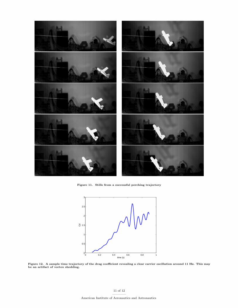
Figure 11. Stills from a successful perching trajectory
0 0.2 0.4 0.6 0.8 10
0.5
1
1.5
2
2.5
3
time (s)
Cd
Figure 12. A sample time trajectory of the drag coefficient revealing a clear carrier oscillation around 11 Hz. This maybe an artifact of vortex shedding.
11 of 12
American Institute of Aeronautics and Astronautics
References
1Wickenheiser, A. M. and Garcia, E., “Longitudinal Dynamics of a Perching Aircraft,” Journal of Aircraft , Vol. 43, No. 5,2006, pp. 1386–1392.
2Wickenheiser, A., Garcia, E., Waszak, and M., “Longitudinal dynamics of a perching aircraft concept,” Proc. SPIE - Int.Soc. Opt. Eng. (USA), Vol. 5764, No. 1, 2005, pp. 192 – 202.
3Wickenheiser, A. M. and Garcia, E., “Optimization of Perching Maneuvers Through Vehicle Morphing,” Journal ofGuidance, Control, and Dynamics, Vol. 31, No. 4, July-August 2008, pp. 815–824.
4Jang, J. S. and Tomlin, C. J., “Autopilot Design for the Stanford DragonFly UAV: Validation through Hardware-in-the-Loop Simulation,” 2001.
5Green, W. E. and Oh, P. Y., “A MAV That Flies Like an Airplane and Hovers Like a Helicopter,” July 2005.6Green, W. E. and Oh, P. Y., “A Fixed-Wing Aircraft for Hovering in Caves, Tunnels, and Buildings,” June 2006.7Cory, R. and Tedrake, R., “On the controllability of Agile Fixed-Wing Flight,” Proceedings of the 2007 Symposium on
Flying Insects and Robots (FIR), August 2007.8Frank, A., McGrew, J. S., Valenti, M., Levine, D., and How, J., “Hover, Transition, and Level Flight Control Design for
a Single-Propeller Indoor Airplane,” AIAA Guidance, Navigation and Control Conference and Exhibit , AIAA, 2007.9Blauwe, H. D., Bayraktar, S., Feron, E., and Lokumcu, F., “Flight Modeling and Experimental Autonomous Hover
Control of a Fixed Wing Mini-UAV at High Angle of Attack,” AIAA Guidance, Navigation and Control Conference andExhibit , 2007.
10Piedmonte, M. and Feron, E., “Aggressive Maneuvering of Autonomous Aerial Vehicles: A Human-Centered Approach,”October 1999.
11Gavrilets, V., Frazzoli, E., Mettler, B., Piedmonte, M., and Feron, E., “Aggressive Maneuvering of Small AutonomousHelicopters: A Human- Centered Approach,” The International Journal of Robotics Research, 2001.
12Sprague, K., Gavrilets, V., Dugail, D., Mettler, B., Feron, E., Martinos, and I., “Design and applications of an avionicssystem for a miniatureacrobatic helicopter,” October 2001.
13Gavrilets, V., Mettler, B., and Feron, E., “Nonlinear Model for a Small-Size Acrobatic Helicopter,” August 2001.14Gavrilets, V., Mettler, B., and Feron, E., “Dynamic Model for a Miniature Aerobatic Helicopter,” .15Gavrilets, V., Martinos, I., Mettler, B., and Feron, E., “Flight test and simulation results for an autonomous aerobatic
helicopter,” 2002.16Gavrilets, V., Martinos, I., Mettler, B., and Feron, E., “Control Logic for Automated Aerobatic Flight of a Miniature
Helicopter,” August 2002.17Bayraktar, S. and Feron, E., “Experiments with small helicopter automated landings at unusual attitudes,” arXiv ,
September 2007.18Bagnell, J. A. and Schneider, J. G., “Autonomous Helicopter Control Using Reinforcement Learning Policy Search
Methods,” May 2001.19Ng, A. Y., Kim, H. J., Jordan, M. I., and Sastry, S., “Autonomous helicopter flight via Reinforcement Learning,” Advances
in Neural Information Processing Systems (NIPS), Vol. 16, 2003.20Ng, Y., A., Coates, A., Diel, M., Ganapathi, V., Schulte, J., Tse, B., Berger, E., Liang, and E., “Autonomous inverted
helicopter flight via reinforcement learning,” International Symposium on Experimental Robotics, 2004.21Abbeel, P., Ganapathi, V., and Ng, A. Y., “Learning vehicular dynamics, with application to modeling helicopters,”
NIPS , 2006.22Abbeel, P., Coates, A., Quigley, M., and Ng, A. Y., “An Application of Reinforcement Learning to Aerobatic Helicopter
Flight,” Proceedings of the Neural Information Processing Systems (NIPS ’07), Vol. 19, December 2006.23Tangler, J. and Kocurek, J. D., “Wind Turbine Post-Stall Airfoil Performance Characteristics Guidelines for Blade-
Element Momentum Methods,” 43rd AIAA Aerospace Sciences Meeting and Exhibit , AIAA, 2005.24Munos, R. and Moore, A., “Variable Resolution Discretization in Optimal Control,” Machine Learning, Vol. 49, No. 2/3,
November/December 2002, pp. 291–323.25Sutton, R. S. and Barto, A. G., Reinforcement Learning: An Introduction, MIT Press, 1998.26Bertsekas, D. P., Dynamic Programming and Optimal Control , Athena Scientific, 2nd ed., 2000.27Tedrake, R. L., Applied Optimal Control for Dynamically Stable Legged Locomotion, Ph.D. thesis, Massachusetts Institute
of Technology, 2004.28Lam, K. and Leung, M., “Asymmetric vortex shedding flow past an inclined flat plate at high incidence,” European
Journal of Mechanics B/Fluids, Vol. 24, 2005.
12 of 12
American Institute of Aeronautics and Astronautics
Related Documents