Experimental Study on Stress Transfer in Reinforced Concrete Corner Column and Beam Joints K. Nishimura, Y. Goto & S. Murai Hokkaido University, Japan A. Kitano Maebashi Institute of Technology, Japan SUMMARY: Reinforced concrete rigid frame structures generally have a corner column jointed with two beams in orthogonal directions. If plastic hinges are designed at the beam ends for ductile frame system, the longitudinal bars need to yield, and capacities of those anchorages and strength of the exterior joint must be evaluated. An objective of this experimental study is to examine a stress transfer mechanism in the corner column and beams joint. Three corner column and beams joint specimens were prepared for tests, and were subjected to static cyclic loads. As results, it can be said that strength at the joint can be evaluated by traditional method; the joint can fail under large displacement even if the joint has 1.5 times larger strength than the beams; the longitudinal bars in a perpendicular beam can effect as anchorage reinforcements; stiffness against torsion around a column axis declines after the damage at the joint. Keywords: R/C, exterior joint, bi-axial load, anchorage 1. INTRODUCTION Reinforced concrete rigid frame structures generally have a corner column jointed with two beams in orthogonal directions, and longitudinal bars in those beams anchor in the column, which part is exterior joint. If plastic hinges are designed at the beam ends for ductile frame system, the longitudinal bars need to yield and capacities of the anchorage and strength of the exterior joint must be evaluated. However, experimental studies on the reinforced concrete corner column and beams joints subjected to bi-directional loads are limited, and specimens in rare studies had quite higher flexural strength in a column than beams at the connection. When the exterior joint in the rigid frame is subjected to lateral load, a compressive strut of concrete is formed in the joint. And the longitudinal bars in the beams, which are anchored in the joint, are recommended to cross the compressive strut in the joint. However, the anchorage of longitudinal bars may be out of the compressive strut when the exterior joint is subjected to bi-directional loads; therefore there is a fear that actual strength of the beam may be the lower than calculation. A rational design method is necessary, which can evaluate performance of anchorage, effects of transverse bars in the joint, and torsion moment at the joint. An objective of this experimental study is to examine a stress transfer mechanism in the corner column and beams joint when the beams yield in flexure, which the flexural strength of the column is a little larger than that of the beams. Three corner column and beams joint specimens of almost half scale were prepared for tests, and were subjected to static cyclic loads. The each of the specimens had a column of a story height and two beams of half a span. The beams were jointed at the centre of the column width. The column had 300 x 300 mm square section, and was subjected to shear load in diagonal direction of the section. The two beams had width of 150 mm and depth of 300 mm, and were subjected to vertical load mutually in the other direction. Calculated flexural strengths of columns were about 1.15 times larger than those of beams in all the specimens. Parameters of the test were diameter of longitudinal bars in the beams, which deformed bars of D13 and D16 were employed, and ratio of calculated shear strength of joint part to calculated flexural strength of the beam, which

Welcome message from author
This document is posted to help you gain knowledge. Please leave a comment to let me know what you think about it! Share it to your friends and learn new things together.
Transcript
Experimental Study on Stress Transfer inReinforced Concrete Corner Column and Beam Joints
K. Nishimura, Y. Goto & S. MuraiHokkaido University, Japan
A. KitanoMaebashi Institute of Technology, Japan
SUMMARY:Reinforced concrete rigid frame structures generally have a corner column jointed with two beams in orthogonaldirections. If plastic hinges are designed at the beam ends for ductile frame system, the longitudinal bars need toyield, and capacities of those anchorages and strength of the exterior joint must be evaluated. An objective ofthis experimental study is to examine a stress transfer mechanism in the corner column and beams joint. Threecorner column and beams joint specimens were prepared for tests, and were subjected to static cyclic loads. Asresults, it can be said that strength at the joint can be evaluated by traditional method; the joint can fail underlarge displacement even if the joint has 1.5 times larger strength than the beams; the longitudinal bars in aperpendicular beam can effect as anchorage reinforcements; stiffness against torsion around a column axisdeclines after the damage at the joint.
Keywords: R/C, exterior joint, bi-axial load, anchorage
1. INTRODUCTION
Reinforced concrete rigid frame structures generally have a corner column jointed with two beams inorthogonal directions, and longitudinal bars in those beams anchor in the column, which part isexterior joint. If plastic hinges are designed at the beam ends for ductile frame system, the longitudinalbars need to yield and capacities of the anchorage and strength of the exterior joint must be evaluated.However, experimental studies on the reinforced concrete corner column and beams joints subjected tobi-directional loads are limited, and specimens in rare studies had quite higher flexural strength in acolumn than beams at the connection. When the exterior joint in the rigid frame is subjected to lateralload, a compressive strut of concrete is formed in the joint. And the longitudinal bars in the beams,which are anchored in the joint, are recommended to cross the compressive strut in the joint. However,the anchorage of longitudinal bars may be out of the compressive strut when the exterior joint issubjected to bi-directional loads; therefore there is a fear that actual strength of the beam may be thelower than calculation. A rational design method is necessary, which can evaluate performance ofanchorage, effects of transverse bars in the joint, and torsion moment at the joint.
An objective of this experimental study is to examine a stress transfer mechanism in the corner columnand beams joint when the beams yield in flexure, which the flexural strength of the column is a littlelarger than that of the beams. Three corner column and beams joint specimens of almost half scalewere prepared for tests, and were subjected to static cyclic loads. The each of the specimens had acolumn of a story height and two beams of half a span. The beams were jointed at the centre of thecolumn width. The column had 300 x 300 mm square section, and was subjected to shear load indiagonal direction of the section. The two beams had width of 150 mm and depth of 300 mm, andwere subjected to vertical load mutually in the other direction. Calculated flexural strengths ofcolumns were about 1.15 times larger than those of beams in all the specimens. Parameters of the testwere diameter of longitudinal bars in the beams, which deformed bars of D13 and D16 were employed,and ratio of calculated shear strength of joint part to calculated flexural strength of the beam, which
the aimed ratios were 0.7 and 1.5. The calculated shear strength of joint wasn’t taken effect oftransverse bars in the joint into account; therefore the strength is shear resistance of concrete. Thestress transfer mechanism in the corner joint was considered based on the test results.
2. EXPERIMENTAL PROGRAM
2.1. Dimension of Specimens and Loading Setup
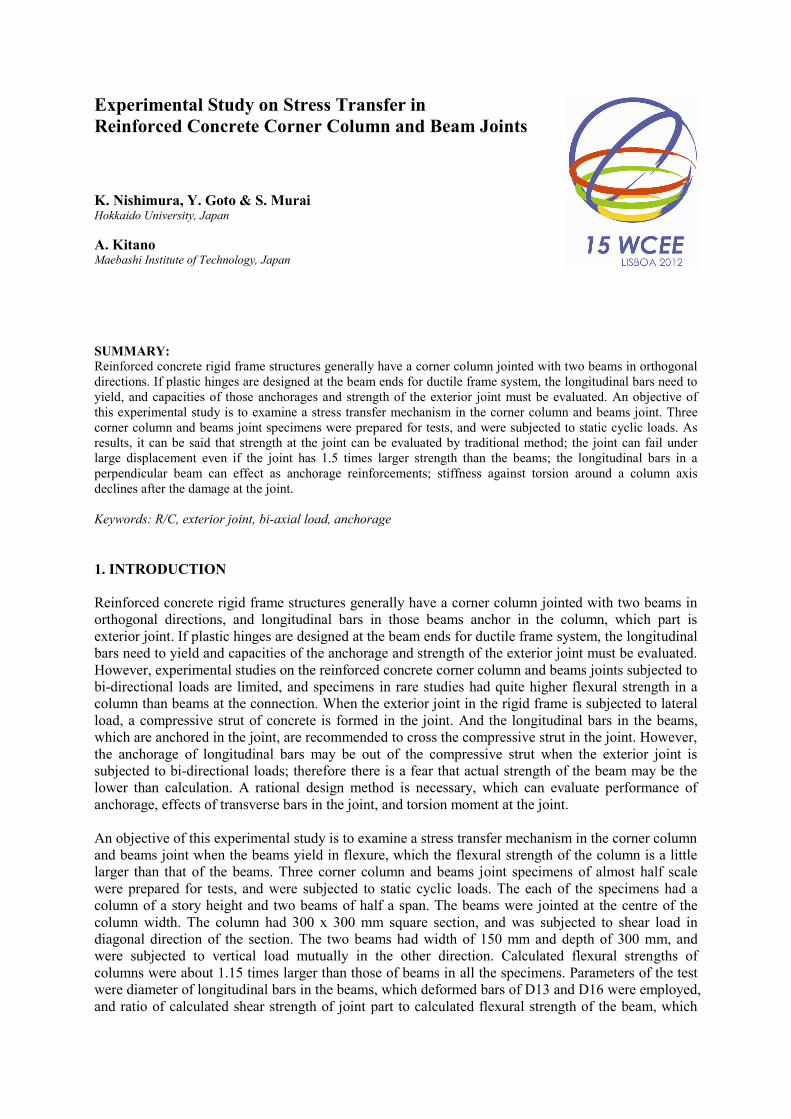
In this test, three specimens of corner column and beams joints were prepared. As shown in Fig. 2.1,all of them had identical column and beam sections those were 300 x 300 mm and 150 x 300 mm,respectively.
Figure 2.1. Dimension of Specimen [EXJ-D3 for bar arrangements]
850 850 850
85
08
75
875
roller
pin
lateral load
axial load
QC
Steelbeam
Steel beam
Reaction floor 850 850 850
850
875
87
5
Displacementtransducer
R
QC
QC
X
Z
X
Y
(side view)
(bottom view)
Measuring frame for R
Measuring frame for
Measuring frame for R
pin
roller
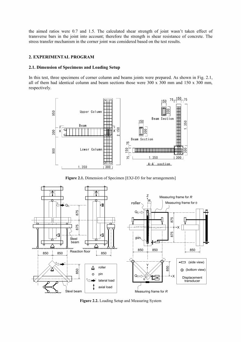
Figure 2.2. Loading Setup and Measuring System

Fig. 2.2 shows loading setup and measuring systems. The column was applied lateral load and axialload with actuators, and the two beams were supported with a steel beam that translate horizontallyand is restricted rotation and vertical translation. A story drift angle, R, was measured withdisplacement transducers, which were fixed on a measuring frame supported with pin and roller atinflection points of the column. A frame for measuring a rotation angle around the column axisbetween the inflection points of the column, which was , was fixed at those points of the column.Strain gages were pasted on longitudinal bars at the fix end section in one side of the column and oneside of the beam, and square shaped transverse bars in the joint on the centres of four sides. The straingages on the longitudinal bars in the column and the beam were located 25 mm apart from a beam faceand a column face, respectively.
2.2. Parameters and Loading Plan
Table 2.1 and Table 2.2 show detail of the specimens and mechanical properties of deformed bars.Concrete strengths were about 34 N/mm2. The detail of joint in Table 2.1 shows arrangement ofreinforcements and anchorage length of longitudinal bars in the beams.
Table 2.1. Detail of SpecimensName of specimens EXJ-D1 EXJ-D2 EXJ-D3FC
*1 [N/mm2]EC
*2 [N/mm2]33.62.6 x 104
34.72.5 x 104
34.92.6 x 104
Part Column Beam Column Beam Column Beam
Section
Longitudinal bar(pg
*3 or pt*4 [%])
8-D13(1.1)
2x8-D13(2.7, 2.8)
12-D10(0.95)
2x3-D16(1.8, 1.6)
12-D10(0.95)
2x4-D13(1.3, 1.3)
Shear reinforcingbar (pw
*5 [%])-D6@50
(0.42)-D4@50
(0.75)-D6@100
(0.21)-D6@100
(0.42)-D6@100
(0.21)-D4@100
(0.37)Axial load [kN]( *6)
302(0.1)
N/A 109(0.035)
N/A 78.5(0.025)
N/A
Reinforcing bar injoint
2x -D6
Detail at joint [mm]
*1: compressive strength of concrete cylinder, *2: 1/3 secant modulus of concrete,*3: gross reinforcement ratio of column, *4: tensile reinforcement ratio of beam, *5 shear reinforcement ratio,*6: ratio of axial load divided by product of section area and FC.
Table 2.2. Mechanical Properties of Deformed BarName of deformed bar D4 D6 D10 D13 D16Nominal section area [mm2] 14.05 31.67 71.33 126.7 198.6Yield strength [N/mm2] 357* 347* 336 353 317Tensile strength [N/mm2] 490 475 491 505 466Yong’s Modulus [x105 N/mm2] 2.1 1.9 1.7 1.9 1.9*: 0.2 % offset method.
Fig. 2.3 shows parameters of this experiment. The parameters of the tests were diameter oflongitudinal bars in the beams and ratio of calculated shear strength of joint part to calculated flexuralstrength of the beam. Therefore arrangements of longitudinal bars in the beams were different to adjust
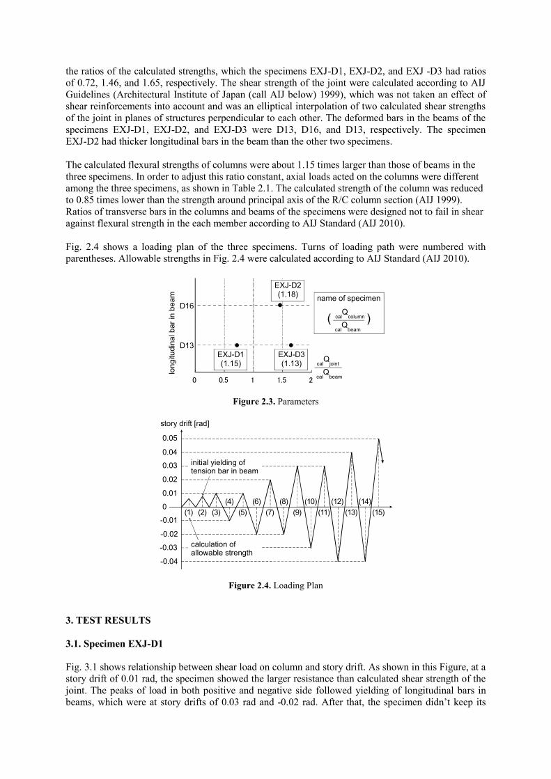
the ratios of the calculated strengths, which the specimens EXJ-D1, EXJ-D2, and EXJ -D3 had ratiosof 0.72, 1.46, and 1.65, respectively. The shear strength of the joint were calculated according to AIJGuidelines (Architectural Institute of Japan (call AIJ below) 1999), which was not taken an effect ofshear reinforcements into account and was an elliptical interpolation of two calculated shear strengthsof the joint in planes of structures perpendicular to each other. The deformed bars in the beams of thespecimens EXJ-D1, EXJ-D2, and EXJ-D3 were D13, D16, and D13, respectively. The specimenEXJ-D2 had thicker longitudinal bars in the beam than the other two specimens.
The calculated flexural strengths of columns were about 1.15 times larger than those of beams in thethree specimens. In order to adjust this ratio constant, axial loads acted on the columns were differentamong the three specimens, as shown in Table 2.1. The calculated strength of the column was reducedto 0.85 times lower than the strength around principal axis of the R/C column section (AIJ 1999).Ratios of transverse bars in the columns and beams of the specimens were designed not to fail in shearagainst flexural strength in the each member according to AIJ Standard (AIJ 2010).
Fig. 2.4 shows a loading plan of the three specimens. Turns of loading path were numbered withparentheses. Allowable strengths in Fig. 2.4 were calculated according to AIJ Standard (AIJ 2010).
0 0.5 1 1.5 2cal
Qbeam
calQ
joint
D16
D13
longitu
din
albar
inbe
am
EXJ-D1(1.15)
EXJ-D2(1.18)
EXJ-D3(1.13)
name of specimen
( )cal
Qbeam
calQ
column
Figure 2.3. Parameters
0.05
0.03
0.02
0.01
-0.03
-0.02
-0.01
0
story drift [rad]
-0.04
0.04
(1) (2) (3)
(4)
(5)
(6)
(7)
(8)
initial yielding oftension bar in beam
calculation ofallowable strength
(10) (12) (14)
(9) (11) (13) (15)
Figure 2.4. Loading Plan
3. TEST RESULTS
3.1. Specimen EXJ-D1
Fig. 3.1 shows relationship between shear load on column and story drift. As shown in this Figure, at astory drift of 0.01 rad, the specimen showed the larger resistance than calculated shear strength of thejoint. The peaks of load in both positive and negative side followed yielding of longitudinal bars inbeams, which were at story drifts of 0.03 rad and -0.02 rad. After that, the specimen didn’t keep its
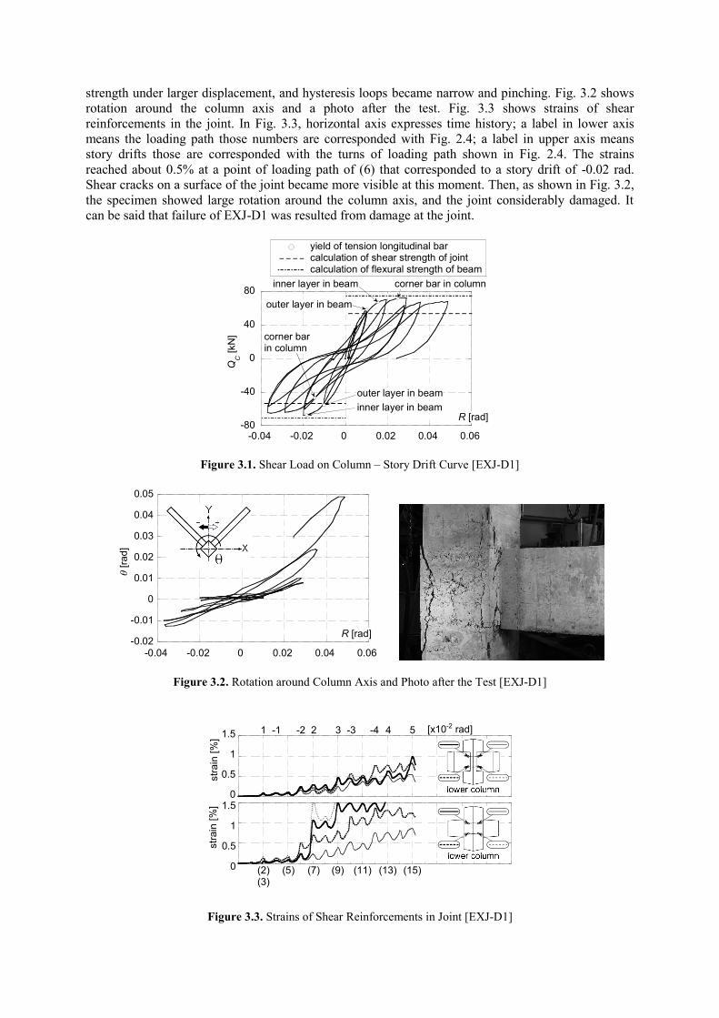
strength under larger displacement, and hysteresis loops became narrow and pinching. Fig. 3.2 showsrotation around the column axis and a photo after the test. Fig. 3.3 shows strains of shearreinforcements in the joint. In Fig. 3.3, horizontal axis expresses time history; a label in lower axismeans the loading path those numbers are corresponded with Fig. 2.4; a label in upper axis meansstory drifts those are corresponded with the turns of loading path shown in Fig. 2.4. The strainsreached about 0.5% at a point of loading path of (6) that corresponded to a story drift of -0.02 rad.Shear cracks on a surface of the joint became more visible at this moment. Then, as shown in Fig. 3.2,the specimen showed large rotation around the column axis, and the joint considerably damaged. Itcan be said that failure of EXJ-D1 was resulted from damage at the joint.
-80
-40
0
40
80
-0.04 -0.02 0 0.02 0.04 0.06
QC
[kN
]
R [rad]
outer layer in beam
inner layer in beam
yield of tension longitudinal barcalculation of shear strength of jointcalculation of flexural strength of beam
corner bar in column
outer layer in beam
inner layer in beam
corner barin column
Figure 3.1. Shear Load on Column – Story Drift Curve [EXJ-D1]
-0.02
-0.01
0
0.01
0.02
0.03
0.04
0.05
-0.04 -0.02 0 0.02 0.04 0.06
[r
ad
]
R [rad]
Figure 3.2. Rotation around Column Axis and Photo after the Test [EXJ-D1]
0
0.5
1
1.5
str
ain
[%]
1 -1 -2 2 3 -3 -4 4 5 [x10-2 rad]
0
0.5
1
1.5
str
ain
[%]
(2)(3)
(5) (7) (9) (11) (13) (15)
Figure 3.3. Strains of Shear Reinforcements in Joint [EXJ-D1]
3.2. Specimen EXJ-D2
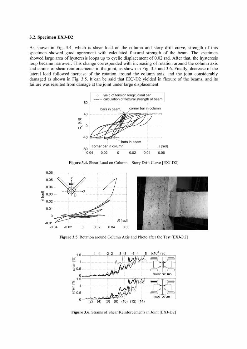
As shown in Fig. 3.4, which is shear load on the column and story drift curve, strength of thisspecimen showed good agreement with calculated flexural strength of the beam. The specimenshowed large area of hysteresis loops up to cyclic displacement of 0.02 rad. After that, the hysteresisloop became narrower. This change corresponded with increasing of rotation around the column axisand strains of shear reinforcements in the joint, as shown in Fig. 3.5 and 3.6. Finally, decrease of thelateral load followed increase of the rotation around the column axis, and the joint considerablydamaged as shown in Fig. 3.5. It can be said that EXJ-D2 yielded in flexure of the beams, and itsfailure was resulted from damage at the joint under large displacement.
-80
-40
0
40
80
-0.04 -0.02 0 0.02 0.04 0.06
QC
[kN
]
R [rad]
bars in beam
yield of tension longitudinal barcalculation of flexural strength of beam
corner bar in column
bars in beam
corner bar in column
Figure 3.4. Shear Load on Column – Story Drift Curve [EXJ-D2]
-0.01
0
0.01
0.02
0.03
0.04
0.05
0.06
-0.04 -0.02 0 0.02 0.04 0.06
[r
ad
]
R [rad]
Figure 3.5. Rotation around Column Axis and Photo after the Test [EXJ-D2]
0
0.5
1
1.5
stra
in[%
]
1 -1 -2 2 3 -3 -4 4 5 [x10-2 rad]
0
0.5
1
1.5
str
ain
[%]
(2) (4) (6) (8) (10) (12) (14)
Figure 3.6. Strains of Shear Reinforcements in Joint [EXJ-D2]
3.3. Specimen EXJ-D3
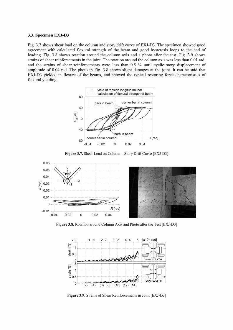
Fig. 3.7 shows shear load on the column and story drift curve of EXJ-D3. The specimen showed goodagreement with calculated flexural strength of the beam and good hysteresis loops to the end ofloading. Fig. 3.8 shows rotation around the column axis and a photo after the test. Fig. 3.9 showsstrains of shear reinforcements in the joint. The rotation around the column axis was less than 0.01 rad,and the strains of shear reinforcements were less than 0.5 % until cyclic story displacement ofamplitude of 0.04 rad. The photo in Fig. 3.8 shows slight damages at the joint. It can be said thatEXJ-D3 yielded in flexure of the beams, and showed the typical restoring force characteristics offlexural yielding.
-80
-40
0
40
80
-0.04 -0.02 0 0.02 0.04
QC
[kN
]
R [rad]
bars in beam
yield of tension longitudinal barcalculation of flexural strength of beam
corner bar in column
bars in beam
corner bar in column
Figure 3.7. Shear Load on Column – Story Drift Curve [EXJ-D3]
-0.01
0
0.01
0.02
0.03
0.04
0.05
0.06
-0.04 -0.02 0 0.02 0.04
[r
ad
]
R [rad]
Figure 3.8. Rotation around Column Axis and Photo after the Test [EXJ-D3]
0
0.5
1
1.5
stra
in[%
]
1 -1 -2 2 3 -3 -4 4 5 [x10-2 rad]
0
0.5
1
1.5
stra
in[%
]
(2) (4) (6) (8) (10) (12) (14)
Figure 3.9. Strains of Shear Reinforcements in Joint [EXJ-D3]
4. CONSIDERATIONS
4.1. Evaluation of Strength
As mentioned above, the strengths of specimens EXJ -D2 and EXJ-D3 can be evaluated withcalculation of the flexural strength of the beam, and the specimens reached their strength at the storydrift of about 0.01 rad. Regarding the strength of specimen EXJ-D1, the maximum value was resultedfrom yield of longitudinal bars in beam. However, large deformations were needed to reach themaximum those were 0.03 rad in positive side and -0.02 rad in negative side. Moreover, the failure ofthis specimen was resulted from damage at the joint.
It is necessary to examine the strength of EXJ-D1 from the viewpoint of structural design. Specifically,the following points must be considered: damages at the joint are undesirable; calculation of the shearstrength of the joint is not taken effects of shear reinforcements into account (AIJ 1999 and AIJ 2010);it is better to evaluate the strength of column-beam joint assembly at almost the same deformationlevel as the other type of failures such as flexural failure of beam or column. Considering deformationat the moment when the specimens EXJ-D2 and EXJ-D3 yielded in flexure, the story drift of 0.01 radcan be an index for evaluating strength of the column and beam joint specimens in this test. And, atthis moment, the damage at the joint was slight because the strains of shear reinforcements were lessthan 0.2 % that meant almost elastic range. Moreover, the strains considerably increased under largerdisplacement than 0.01 rad. It is appropriate to compare the resistance at 0.01 rad with calculated shearstrength of the joint, and those showed good agreement as shown in Fig. 3.1. Therefore, it can be saidthat the strength of the joint part can be evaluated by traditional method that is an ellipticalinterpolation of two calculated shear strengths of the joint in planes of structure perpendicular to eachother.
4.2. Effects of Thick Deformed Bar
The specimens EXJ-D2 and EXJ-D3 had almost the same calculated strength of beam and the sameratios of calculated strengths of joint and column to calculated strength of beam (see Fig. 2.3). Theparameter for these two specimens was diameter of deformed bars in the beams. The deformed bars inEXJ-D2 were thicker than those in EXJ -D3 (see Table 2.1 and Fig. 2.3). The specimens EXJ-D2 andEXJ-D3 had the ratios of calculated strength of joint to beam of 1.46 and 1.65, respectively.
The restoring force characteristics were almost agreed between these specimens until cyclicdisplacements of 0.02 rad amplitude. After that, the strains of shear reinforcements in the joint androtation around the column axis of EXJ-D2 increased as shown in Figs. 3.5 and 3.6, and narrowingand pinching of hysteresis loops followed as shown in Fig. 3.4. And then the joint part considerablydamaged as shown in the photo in Fig.3.5. It can be said, when deformed bars of large diameter areemployed for longitudinal bars in beam, the joint can damage under large cyclic displacement even ifcalculated shear strength of the joint is 1.5 times lager than calculated flexural strength of the beam.
4.3. Behaviours after Damage at Joint
Usually, exterior joint of a single beam tend to shows narrow loop because of slipping at anchorage.However, in this test, all the specimens showed large loops until the joint part damaged, andbehaviours of slipping at the anchorages couldn’t be seen in the loops as shown in Figs. 3.1, 3.4, and3.7. I can be considered that longitudinal bars in a perpendicular beam effected as anchoragereinforcements against tension of longitudinal bars in the beam of the other side. This effect must beexamined in detail in future.
The significant results could be seen in this experiment that the damage at the joint caused aconsiderable lowering of stiffness against torsion around the column axis. Because the corner columns
were located away from the centre of stiffness against torsion on floor plans in general, the lowering ofstiffness against torsion around the column axis can result unexpected large displacement by a torsionresponse of a frame structure.
5. CONCLUSIONS
Three corner column and beams joint specimens were prepared for static cyclic loading tests, whichtwo beams were jointed to the column perpendicular to each other. The columns and the beams hadsquare and rectangle sections, respectively. Lateral load was applied on the column in diagonaldirection of the column section as the two beams were subjected to vertical force mutually in the otherdirection. The parameters of the test were diameter of longitudinal bars in the beams and ratio ofcalculated shear strength of joint part to calculated flexural strength of the beams. The calculatedflexural strengths of columns were about 1.15 times larger than those of beams in these threespecimens. As results, the following conclusions could be found.
1. Strength of a joint part can be evaluated by traditional method that is an elliptical interpolation oftwo calculated shear strengths of the joint in planes of structure perpendicular to each other.
2. When deformed bars of large diameter are employed for longitudinal bars in beam, the joint candamage under large cyclic displacement that makes hysteresis loops narrow even if calculatedshear strength of the joint is 1.5 times lager than calculated flexural strength of the beam.
3. Longitudinal bars in a perpendicular beam can effect as anchorage reinforcements against tensionof longitudinal bars in the other beam.
4. The damage at the joint part causes a considerable lowering of stiffness against torsion around acolumn axis.
ACKNOWLEDGEMENTThis work was supported by KAKENHI (23760519, Grant-in-Aid for Young Scientists (B), the Japan Societyfor the Promotion of Science (JSPS)). The materials for this experiment, cement and PC steel bars, werepresented from TAIHEIYO CEMENT CORPORATION and NS HOKKAI SEISEN Co., Ltd., respectively. Theauthors acknowledge all these supports.
REFERENCES
Architectural Institute of Japan (2010). AIJ Standard for Structural Calculation of Reinforced ConcreteStructures, revised 2010, Architectural Institute of Japan, (in Japanese).
Architectural Institute of Japan (1999). Design Guidelines for Earthquake Resistant Reinforced ConcreteBuildings Based on Inelastic Displacement Concept, Architectural Institute of Japan, (in Japanese).
Adachi, M., Ishida, K., Fujii, S., Watanabe, F., and Morita, S., (1995). Bi-directional Seismic Loading Tests ofHigh-strength R/C Corner Column-Beam Subassemblage, Part 1: Outline of Experimental Results,Summaries of Technical Papers of Annual Meeting, AIJ, 91-92, (in Japanese).
Cui, J., Ishida, K., Fujii, S., and Morita, S., (1996). Shear Capacity of R/C Corner Column-Beam Subassemblageunder Bi-directional Seismic Loadings, Part 1: Load-Deformation Capacities, Summaries of TechnicalPapers of Annual Meeting, AIJ, 721-722, (in Japanese).
Ishida, K., Adachi, M., Fujii, S., Watanabe, F., and Morita, S., (1995), Bi-directional Seismic Loading Tests ofHigh-strength R/C Corner Column-Beam Subassemblage, Part 2: Characteristic Behaviors of Specimens,Summaries of Technical Papers of Annual Meeting, AIJ, 93-94, (in Japanese).
Ishida, K., Cui, J., Fujii, S., and Morita, S., (1996). Shear Capacity of R/C Corner Column-Beam Subassemblageunder Bi-directional Seismic Loadings, Part 2: Characteristics Behaviors under Bi-directional Loadings,Summaries of Technical Papers of Annual Meeting, AIJ, 723-724, (in Japanese).
Related Documents