EV 30 Installation Instructions 810496-00 Bottom Loading and Unloading System EV 30

Welcome message from author
This document is posted to help you gain knowledge. Please leave a comment to let me know what you think about it! Share it to your friends and learn new things together.
Transcript
1
EV 30Installation Instructions 810496-00Bottom Loading and Unloading System EV 30

2
3
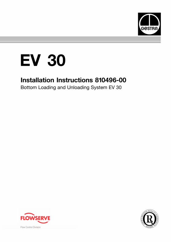
Fig. 1
Dimensions
4
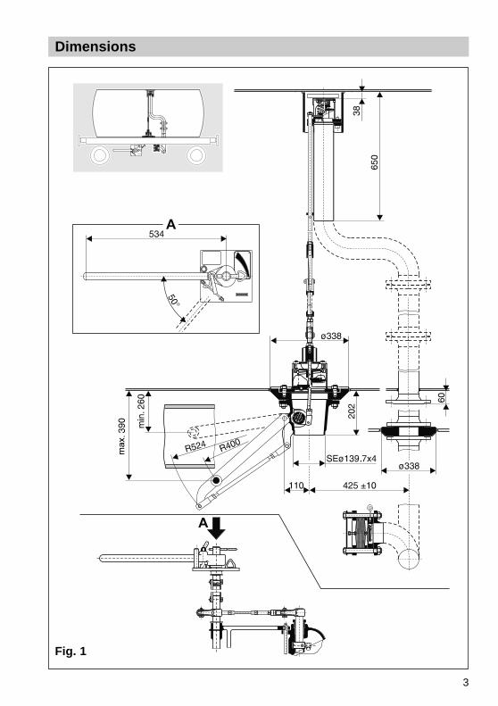
Functional elements
H
GF
E
B 4
B 3
D
CB
A
B 1Lever at limit stop
* welded directly intotank shell
** boiler port withvalve-mounting flange
I
J
B 1
L R
M
N
N 1
K
Fig. 2
Fig. 3
5
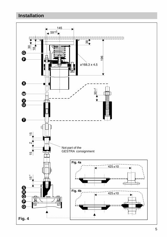
Installation
Fig. 4
Not part of theGESTRA consignment
G
F
X
W
VU
T
SRQPO
6
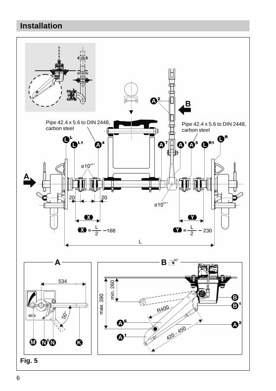
Installation
L L
L L1 A 4
A 2
A 7 A 1 A 5 L R1L R
M N1 N K
A 6
A 1
B 1B
A 2
Fig. 5
Pipe 42.4 x 5.6 to DIN 2448,carbon steel
Pipe 42.4 x 5.6 to DIN 2448,carbon steel
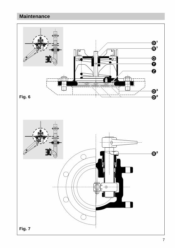
7
Maintenance
B 2
D 1
R 1
OY
Z
D 3
D 2Fig. 6
Fig. 7
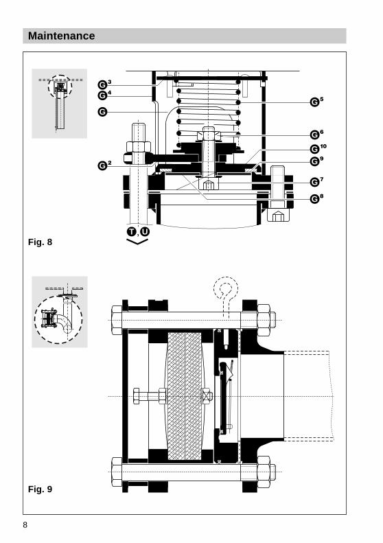
8
Maintenance
G 3
G 4
G
G 2
T U
G 8
G 7
G 9G 10
G 6
G 5
Fig. 8
Fig. 9
9
Manual operating mechanism EV 30
Operating mechanism BV 50, DN 150 mm
Valve mounting flange, DN 125/150 mm
Bottom valve UV 70, DN 125 mm
Actuating rod assembly with threaded bush for adjustment
Support for gas balance pipe (not included in the GESTRA consignment)
Vent valve LV 50, DN 80 mm
Connecting pipe LV 50 with rod assembly guide
Standpipe for gas balance pipe (not included in the GESTRA consignment),
– optional valve mounting flange not represented –
Vacuum breaker FV 10
Hand lever EV 30
Base plate EV 30
Indicator EV 30
Locking lever with hook for positions OPEN and CLOSED
Guide for hand lever
All other items will be explained in the following pages and are therefore not listed here.
N 1
Key
B
C
D
G
H
A
E
I
J
K
M
L
F
N
10
Contents
Safety note ....................................................................................................................11Danger ..........................................................................................................................11
Important Notes
Page
Explanatory Notes
System description .......................................................................................................12Function ........................................................................................................................12Design ...........................................................................................................................12General technical data ..................................................................................................13Technical data of bottom valve UV 70 ..........................................................................13Technical data of vent valve LV 50 DN 80 mm .............................................................13Technical data of swing check valve fitted in FV 10 .................................................... 13Technical data of hand lever ....................................................................................... 13
Tools ..............................................................................................................................15Installation materials .....................................................................................................15Bottom valve with operating mechanism ......................................................................15Vent valve and standpipe (internal gas balance pipe) ..................................................17
Installation
Maintenance
Tools ..............................................................................................................................19Bottom valve: Exchanging gasket .................................................................................19Operating mechanism: Re-tightening stuffing box .......................................................20Vent valve: Exchanging gasket .....................................................................................20
Open loading and unloading system EV 30 .................................................................22Close loading and unloading system EV 30 .................................................................22
Operation
11
Important Notes
Safety Note
Use bottom loading system EV 30 only for loading and unloading tanks designedfor transporting products which are liquid at normal outside temperatures(cf. temperature ratings on page 13). The system may only be installed byqualified staff.
Qualified staff are those persons who have achieved a recognised level ofcompetence appropriate to the installation and commissioning of this equipment.
Danger
Do not undertake any installation or maintenance work unless the mobiletank is completely empty and free of gas. Escaping vapours or gasescan endanger the life and health of the person entrusted with theinstallation or maintenance and cause damage to property.
12
Explanatory Notes
System Description
The bottom loading system EV 30 consists of EV 30 DN 125 mm type F for liquidphase and EV 30 DN 80 mm type G for gas phase (gas balance pipe) and is used inmobile tanks, e.g. rail tank cars.The system meets the requirements of the following rules:
■ GGVE/RID Appendix XI
■ TRT 024, TRT 006, TRT 30
Scope of Supply
EV 30 DN 125 mm type F for liquid phase consisting of:1 Valve mounting flange DN 125/150 mm (on request)1 Bottom valve UV 70 DN 125 mm1 Operating mechanism BV 50 DN 150 mm1 Manual operating mechanism for EV 30
EV 30 DN 80 mm type G for gas phase consisting of:1 Valve mounting flange LV 50 DN 80 mm (on request)1 Vent valve LV 50 DN 80 mm with operating rod1 Vacuum breaker FV 10
EV 30 DN 125 mm type F and EV 30 DN 80 mm type G can also be used singly.
Function
The bottom valve UV 70 DN 125 mm serves as first internal shut-off according toGGVE/RID. The opening mechanism for the bottom valve UV 70 is incorporated inthe operating mechanism BV 50 on to which the corresponding manifold for loading/unloading tank cars can be welded.
The valves for liquid and gas phases can be operated independently of each otherwith the aid of hand levers. When the valve is in the open position the hand lever isautomatically locked. Visual position indication is provided by indicators on both sidesof the tank car.
The vent valve and the bottom valve are interlinked by means of a connecting rod,which means that the vent valve is opened when the bottom valve is being opened.The connecting rod also prevents the vent valve from opening when the fluid issloshing about in the tank.
The vacuum breaker FV 10 fitted in the gas balance pipe of the tank car opens ifnegative pressure builds up when the gas balance pipe is not connected to thetank car.
13
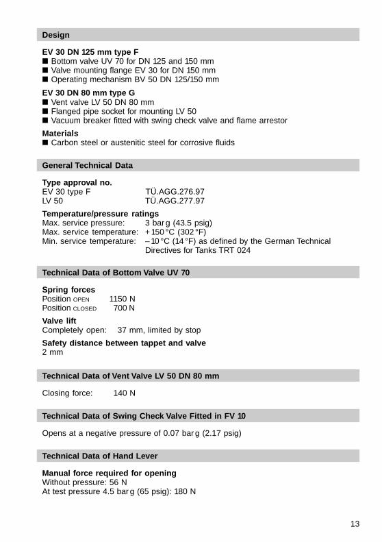
Design
EV 30 DN 125 mm type F■ Bottom valve UV 70 for DN 125 and 150 mm■ Valve mounting flange EV 30 for DN 150 mm■ Operating mechanism BV 50 DN 125/150 mm
EV 30 DN 80 mm type G■ Vent valve LV 50 DN 80 mm■ Flanged pipe socket for mounting LV 50■ Vacuum breaker fitted with swing check valve and flame arrestor
Materials■ Carbon steel or austenitic steel for corrosive fluids
General Technical Data
Type approval no.EV 30 type F TÜ.AGG.276.97LV 50 TÜ.AGG.277.97
Temperature/pressure ratingsMax. service pressure: 3 bar g (43.5 psig)Max. service temperature: + 150 °C (302 °F)Min. service temperature: – 10 °C (14 °F) as defined by the German Technical
Directives for Tanks TRT 024
Technical Data of Bottom Valve UV 70
Spring forcesPosition OPEN 1150 NPosition CLOSED 700 N
Valve liftCompletely open: 37 mm, limited by stop
Safety distance between tappet and valve2 mm
Technical Data of Vent Valve LV 50 DN 80 mm
Closing force: 140 N
Technical Data of Swing Check Valve Fitted in FV 10
Opens at a negative pressure of 0.07 bar g (2.17 psig)
Technical Data of Hand Lever
Manual force required for openingWithout pressure: 56 NAt test pressure 4.5 bar g (65 psig): 180 N
14
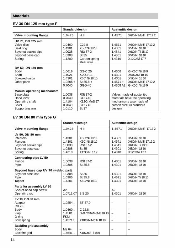
Materials
EV 30 DN 125 mm type FStandard design Austenitic design
Valve mounting flange 1.0425 H II 1.4571 X6CrNiMoTi 1712 2
UV 70, DN 125 mmValve disc 1.0460 C22.8 1.4571 X6CrNiMoTi 1712 2Seat ring 1.4301 X5CrNi 18 10 1.4301 X5CrNi 18 10Bayonet socket pipe 1.0038 RSt 37-2 1.4541 X6CrNiTi 18 10Bayonet base cap 1.0308 St 35 1.4301 X5CrNi 18 10Spring 1.1200 Carbon spring 1.4310 X12CrNi 17 7
steel wire
BV 50, DN 150 mmBody 1.0619 GS-C 25 1.4308 G-X6CrNi 18 9Shaft 1.4021 X20Cr 13 1.4301 X50CrNi 18 15Screwed union 1.4301 X5CrNi 18 10 1.4301 X5CrNi 18 10Other parts 1.0305 + St 35.8 + 1.4571 + X6CrNiMoTi 1712 2
0.7040 GGG-40 1.4308 A2 G-X6CrNi 18 9
Manual operating mechanismBase plate 1.0038 RSt 37-2 Valves made of austeniticHand lever 0.7040 GGG-40 materials have the operatingOperating shaft 1.4104 X12CrMoS 17 mechanisms also made ofLever 0.7040 GGG-40 carbon steel (= standardSupporting arm 1.0110 St 37 design)
EV 30 DN 80 mm type GStandard design Austenitic design
Valve mounting flange 1.0425 H II 1.4571 X6CrNiMoTi 1712 2
LV 50, DN 80 mmInternals 1.4301 X5CrNi 18 10 1.4301 X5CrNi 18 10Flanges 1.4301 X5CrNi 18 10 1.4571 X6CrNiMoTi 1712 2Bayonet socket pipe 1.0038 RSt 37-2 1.4541 X6CrNiTi 18 10Bayonet base cap 1.0308 St 35 1.4301 X5CrNi 18 10Spring 1.4310 X12CrNi 17 7 1.4310 X12CrNi 17 7
Connecting pipe LV 50Flange 1.0038 RSt 37-2 1.4301 X5CrNi 18 10Pipe 1.0305 St 35.8 1.4301 X5CrNi 18 10
Bayonet base cap UV 70 (welded part)Bayonet base cap 1.0308 St 35 1.4301 X5CrNi 18 10Pipe 1.0305 St 35.8 1.4571 X6CrNiTi 18 10Tappet 1.4301 X5CrNi 18 10 1.4301 X5CrNi 18 10
Parts for assembly LV 50Socket-head cap screw A2 A2Operating rod 1.0711.07 9 S 20 1.4301 X5CrNi 18 10
FV 10, DN 80 mmAdaptor 1.0254... ST 37.0 – –CB 26Body 1.0460... C 22.8 – –Flap 1.4581... G-X7CrNiMoNb 18 10 – –O-ring FKM – – –Bow spring 1.4571K X10CrNiMoTi 18 10 – –
Backfire grid assemblyBody Ms 64 – – –Backfire grid 1.4541... X10CrNiTi 18 9
15
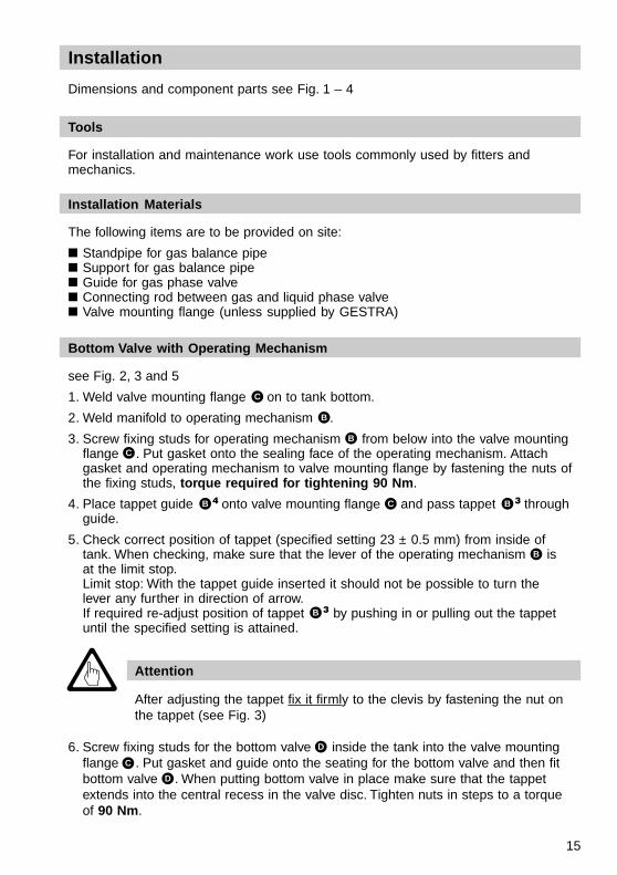
Installation
Tools
For installation and maintenance work use tools commonly used by fitters andmechanics.
Dimensions and component parts see Fig. 1 – 4
Installation Materials
The following items are to be provided on site:
■ Standpipe for gas balance pipe■ Support for gas balance pipe■ Guide for gas phase valve■ Connecting rod between gas and liquid phase valve■ Valve mounting flange (unless supplied by GESTRA)
Bottom Valve with Operating Mechanism
see Fig. 2, 3 and 5
1. Weld valve mounting flange on to tank bottom.
2. Weld manifold to operating mechanism .
3. Screw fixing studs for operating mechanism from below into the valve mountingflange . Put gasket onto the sealing face of the operating mechanism. Attachgasket and operating mechanism to valve mounting flange by fastening the nuts ofthe fixing studs, torque required for tightening 90 Nm.
4. Place tappet guide onto valve mounting flange and pass tappet throughguide.
5. Check correct position of tappet (specified setting 23 ± 0.5 mm) from inside oftank. When checking, make sure that the lever of the operating mechanism isat the limit stop.Limit stop: With the tappet guide inserted it should not be possible to turn thelever any further in direction of arrow.If required re-adjust position of tappet by pushing in or pulling out the tappetuntil the specified setting is attained.
Attention
After adjusting the tappet fix it firmly to the clevis by fastening the nut onthe tappet (see Fig. 3)
6. Screw fixing studs for the bottom valve inside the tank into the valve mountingflange . Put gasket and guide onto the seating for the bottom valve and then fitbottom valve . When putting bottom valve in place make sure that the tappetextends into the central recess in the valve disc. Tighten nuts in steps to a torqueof 90 Nm.
C
B
B
C
B 4 C B 3
B 3
B
D
C
D
16
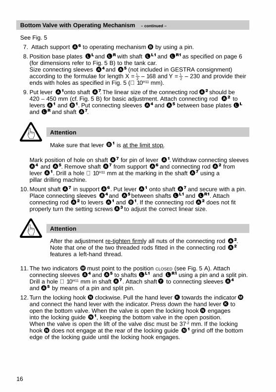
Bottom Valve with Operating Mechanism – continued –
See Fig. 5
7. Attach support to operating mechanism by using a pin.
8. Position base plates and with shaft and as specified on page 6(for dimensions refer to Fig. 5 B) to the tank car.Size connecting sleeves and (not included in GESTRA consignment)according to the formulae for length X =
L2 – 168 and Y =
L2 – 230 and provide their
ends with holes as specified in Fig. 5 (∅ 10H11 mm).
9. Put lever onto shaft . The linear size of the connecting rod should be420 – 450 mm (cf. Fig. 5 B) for basic adjustment. Attach connecting rod tolevers and . Put connecting sleeves and between base platesand and shaft .
Attention
Make sure that lever is at the limit stop.
Mark position of hole on shaft for pin of lever . Withdraw connecting sleeves and . Remove shaft from support and connecting rod from
lever . Drill a hole ∅ 10H11 mm at the marking in the shaft using apillar drilling machine.
10. Mount shaft in support . Put lever onto shaft and secure with a pin.Place connecting sleeves and between shafts and . Attachconnecting rod to levers and . If the connecting rod does not fitproperly turn the setting screws to adjust the correct linear size.
Attention
After the adjustment re-tighten firmly all nuts of the connecting rod .Note that one of the two threaded rods fitted in the connecting rodfeatures a left-hand thread.
11. The two indicators must point to the position CLOSED (see Fig. 5 A). Attachconnecting sleeves and to shafts and using a pin and a split pin.Drill a hole ∅ 10H11 mm in shaft . Attach shaft to connecting sleevesand by means of a pin and split pin.
12. Turn the locking hook clockwise. Pull the hand lever towards the indicatorand connect the hand lever with the indicator. Press down the hand lever toopen the bottom valve. When the valve is open the locking hook engagesinto the locking guide , keeping the bottom valve in the open position.When the valve is open the lift of the valve disc must be 37-2 mm. If the lockinghook does not engage at the rear of the locking guide grind off the bottomedge of the locking guide until the locking hook engages.
A 6 B
L L L R L L1 L R1
A 4 A 5
A 1 A 7 A 2
A 2
A 1 B 1 A 4 A 5 L L
L R A 7
B 1
A 7 A 1
A 4 A 6
A 7
A 7
A 5
A 1A 7 A 2
A 6 A 1 A 7
A 4
B 1L L1
A 2 A 1 A 2A 5 L R1
A 3
A 2
A 2
M
A 4 A 5 L L1 L R1
A 7 Y
A 5A 4
N K M
K
N
N 1
N 1N
17
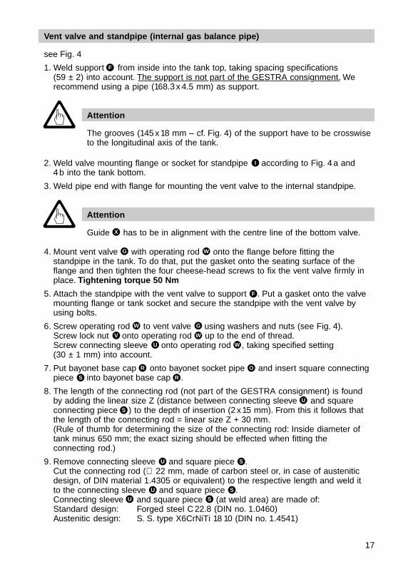
see Fig. 4
1. Weld support from inside into the tank top, taking spacing specifications(59 ± 2) into account. The support is not part of the GESTRA consignment. Werecommend using a pipe (168.3 x 4.5 mm) as support.
Vent valve and standpipe (internal gas balance pipe)
Attention
The grooves (145 x 18 mm – cf. Fig. 4) of the support have to be crosswiseto the longitudinal axis of the tank.
Attention
Guide has to be in alignment with the centre line of the bottom valve.
2. Weld valve mounting flange or socket for standpipe according to Fig. 4 a and4 b into the tank bottom.
3. Weld pipe end with flange for mounting the vent valve to the internal standpipe.
4. Mount vent valve with operating rod onto the flange before fitting thestandpipe in the tank. To do that, put the gasket onto the seating surface of theflange and then tighten the four cheese-head screws to fix the vent valve firmly inplace. Tightening torque 50 Nm
5. Attach the standpipe with the vent valve to support . Put a gasket onto the valvemounting flange or tank socket and secure the standpipe with the vent valve byusing bolts.
6. Screw operating rod to vent valve using washers and nuts (see Fig. 4).Screw lock nut onto operating rod up to the end of thread.Screw connecting sleeve onto operating rod , taking specified setting(30 ± 1 mm) into account.
7. Put bayonet base cap onto bayonet socket pipe and insert square connectingpiece into bayonet base cap .
8. The length of the connecting rod (not part of the GESTRA consignment) is foundby adding the linear size Z (distance between connecting sleeve and squareconnecting piece ) to the depth of insertion (2 x 15 mm). From this it follows thatthe length of the connecting rod = linear size Z + 30 mm.(Rule of thumb for determining the size of the connecting rod: Inside diameter oftank minus 650 mm; the exact sizing should be effected when fitting theconnecting rod.)
9. Remove connecting sleeve and square piece .Cut the connecting rod (∅ 22 mm, made of carbon steel or, in case of austeniticdesign, of DIN material 1.4305 or equivalent) to the respective length and weld itto the connecting sleeve and square piece .Connecting sleeve and square piece (at weld area) are made of:Standard design: Forged steel C 22.8 (DIN no. 1.0460)Austenitic design: S. S. type X6CrNiTi 18 10 (DIN no. 1.4541)
F
I
X
G W
F
GW
WV
WU
OR
RS
U
S
SU
SU
SU
18
Vent valve and standpipe (internal gas balance pipe) – continued –
10. Use operating rod to open the vent valve . Fix it in place by inserting asuitable fixing pin (∅ 4 mm) into the hole above the guide .Pass connecting rod into the guide pipe of the bayonet base cap andscrew it into the connecting sleeve by turning it to the right until theadjustment setting 30 ± 1 mm is attained. Tighten lock nut , remove fixingpin and close the vent valve .
Checking the adjustmentThe square piece has to protrude 15 + 2 mm from the guide pipe.It must be easily possible to push the complete operating rod assembly(connecting rod and operating rod weigh approx. 8 kg) smoothly approx.6 mm upwards (vent valve does not open yet, i. e. idle lift).
If this is not possible modify the adjustment setting in such a way that thespecified setting (15 +2 mm) is maintained and the idle lift of the valve(6 ± 0.5 mm) is also taken into account. Secure the bayonet base cap byusing hexagon-head bolts M8 x 40 and nuts M8 .
GW
X
T R
U
V
G
S
T W
G
R
PQ
19
See Fig. 2, 4, 6
1. Loosen connecting rod (linked with and ) from bottom valve.
2. Unscrew fixing bolts of bayonet base cap . Pull bayonet base cap out of thebayonet socket pipe .
3. Use manual operating mechanism to open the bottom valve.
4. Fix valve disc by inserting a pin ∅ 5 mm into the hole .
5. Use manual operating mechanism to close the bottom valve. The valve disc iskept in the open position by virtue of the fixing pin.
6. Remove valve disc with guide and spring from bayonet socket pipe.
7. Check adjustment setting 23 ± 0.5 mm at tappet of the operating mechanism(see Fig. 2) and, if necessary, adjust the tappet as described in the section“Installation”.
8. Undo the three hexagon-head screws fastening the mounting base to thevalve disc . Remove the mounting base and gasket .
9. Put new gasket into the valve disc, place mounting base onto the valve discand fasten the three hexagon-head screws; torque required for tightening:18 Nm.
10. Put valve disc with guide and spring into the bayonet socket pipe and guideinto the bayonet base cap.
11. Push hand lever in the opening position.
For installation and maintenance work use tools commonly used by fitters andmechanics.
Maintenance
Tools
Bottom Valve: Replacing Gasket
Attention
Before carrying out any maintenance work inside the tank make sure thatthe latter is accessible and sufficiently aearated.
After servicing check the adjustments as specified in the section“Installation”.
Attention
Make sure that the tappet extends into the recess in the valve disc.
We recommend to replace the gaskets of the bottom valve and the vent valve afterevery tank inspection.
T S U
R
O
D 1 Y
D 1 R 1
B 3
D 2 D 3
D 3D 1 Z
D 3
R
B 3
20
Bottom Valve: Replacing Gasket – continued –
Operating Mechanism: Retightening Stuffing Box
12. Remove fixing pin from the hole and close the bottom valve.
13. Put bayonet base cap into bayonet socket pipe and secure with bolts.
14. Attach connecting rod to bottom valve.
See Fig. 7
Normally it is not necessary to re-tighten the stuffing box between tank carinspections.The stuffing box is, to a certain degree, self-tightening.
Inserting additional packing ring:
1. Undo screwed union , six-point socket of spanner: 55 A. F
2. Take disk springs and pressure pad off the stuffing box.
3. Insert additional packing ring.
4. Put gland and disk springs onto the stuffing box.
5. Fasten screwed union to stuffing box and preload disk springs.
Vent Valve: Exchanging Gasket
See Fig. 4, 8
1. Loosen connecting rod (linked with and ) from the bottom valve.
2. Detach internal gas balance pipe from valve mounting flange or pipe socket.
3. Undo the four fixing screws of the vent valve.
4. Detach the connecting rod from the driving pin of the vent valve.
5. Remove bayonet base cap by pulling it down and turning it anticlockwise outof the bayonet socket pipe .
B 2
Y
R O
B 2
G 2
G 3
G 4
T S U
Required spare parts:
Designation Material Ref. no.
Gasket FPM 049230
Gasket PTFE 048571Please state the reference number when ordering these parts at GESTRA.
Required spare parts:
Designation Material Ref. no.
Packing PTFE 048648Please state the reference number when ordering these parts at GESTRA.
21
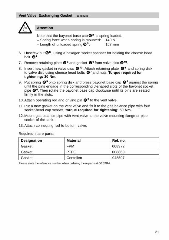
Attention
Note that the bayonet base cap is spring loaded.– Spring force when spring is mounted: 140 N– Length of unloaded spring : 157 mm
Vent Valve: Exchanging Gasket – continued –
6. Unscrew nut , using a hexagon socket spanner for holding the cheese headbolt .
7. Remove retaining plate and gasket from valve disc .
8. Insert new gasket in valve disc . Attach retaining plate and spring diskto valve disc using cheese head bolts and nuts. Torque required fortightening: 30 Nm.
9. Put spring onto spring disk and press bayonet base cap against the springuntil the pins engage in the corresponding J-shaped slots of the bayonet socketpipe . Then rotate the bayonet base cap clockwise until its pins are seatedfirmly in the slots.
10. Attach operating rod and driving pin to the vent valve.
11. Put a new gasket on the vent valve and fix it to the gas balance pipe with foursocket-head cap screws, torque required for tightening: 50 Nm.
12. Mount gas balance pipe with vent valve to the valve mounting flange or pipesocket of the tank.
13. Attach connecting rod to bottom valve.
G 3
G 5
G 6
G 7
G 8 G 9 G 10
G 10 G 8
G 7
G 3G 5
G 4
G 2
Required spare parts:
Designation Material Ref. no.
Gasket FPM 008372
Gasket PTFE 008860
Gasket Centellen 048597Please state the reference number when ordering these parts at GESTRA.
22
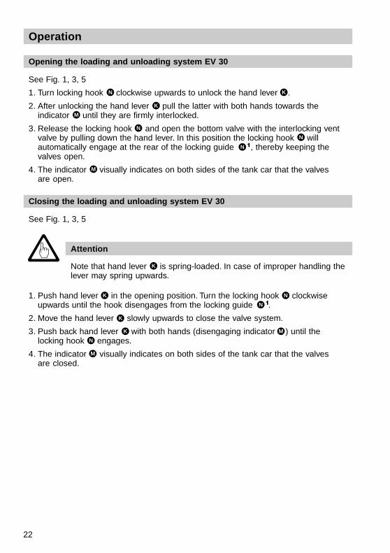
Operation
Opening the loading and unloading system EV 30
See Fig. 1, 3, 5
1. Turn locking hook clockwise upwards to unlock the hand lever .
2. After unlocking the hand lever pull the latter with both hands towards theindicator until they are firmly interlocked.
3. Release the locking hook and open the bottom valve with the interlocking ventvalve by pulling down the hand lever. In this position the locking hook willautomatically engage at the rear of the locking guide , thereby keeping thevalves open.
4. The indicator visually indicates on both sides of the tank car that the valvesare open.
Closing the loading and unloading system EV 30
See Fig. 1, 3, 5
Attention
Note that hand lever is spring-loaded. In case of improper handling thelever may spring upwards.
1. Push hand lever in the opening position. Turn the locking hook clockwiseupwards until the hook disengages from the locking guide .
2. Move the hand lever slowly upwards to close the valve system.
3. Push back hand lever with both hands (disengaging indicator ) until thelocking hook engages.
4. The indicator visually indicates on both sides of the tank car that the valvesare closed.
N 1
N 1
N K
K
M
N
N
M
K
K N
K
K M
N
M

23
24
GESTRA Gesellschaften · GESTRA Companies · Sociétés GESTRA · Sociedades Gestra · Società GESTRAVertretungen weltweit · Agencies all over the world · Représentations dans le monde entier · Representaciones en todo el mundo · Agenzie in tutto il mondo
810496-00/1299c · © 1997 GESTRA GmbH · Bremen · Printed in Germany
GESTRA GmbH
Postfach 10 54 60D-28054 Bremen
Hemmstraße 130D-28215 Bremen
Tel. +49 (0) 421 35 03-0Fax +49 (0) 421 35 03-393Internet www.gestra.deE-mail [email protected]
An Invensys company
®
Polska
GESTRA POLONIA Spolka z o.o.Ul. Schuberta 104PL-80-172 GdanskTel. (058) 30610 02Fax (058) 30610 03
Portugal
GESTRA PORTUGUESA VALVULAS LDA.Av. Dr. Antunes Guimarães, 1159P-4100 PortoTel. (02) 61075 51Fax (02) 61075 75
Italia
ITALGESTRA S.r.l.Via Carducci 125l-20099 S.S. Giovanni (MI)Tel. (02) 2 6297-0Fax (02) 26 2974 60
GESTRA ESPAÑOLA S.A.Luis Cabrera, 86-88E-28002 MadridTel. (091) 5 152 032Fax (091) 4 136747; (091) 5152036
España
GESTRA S.A.R.L.10 Avenue du Centaure, BP 8263F-95801 CERGY PONTOISETél. (01) 34.43.26.60Fax (01) 34.43.26.87
France
GESTRA Gesellschaften · GESTRA Companies · Sociétés GESTRA · Sociedades Gestra · Società GESTRAVertretungen weltweit · Agencies all over the world · Représentations dans le monde entier · Representaciones en todo el mundo · Agenzie in tutto il mondo
GESTRA GmbH
Postfach 10 54 60D-28054 BremenMünchener Str. 77D-28215 BremenTel. +49 (0) 421 35 03-0Fax +49 (0) 421 35 03-393E-mail [email protected] www.gestra.de
A Unit of Flowserve Corporation
Polska
GESTRA POLONIA Spolka z o.o.Ul. Schuberta 104, P. O. Box 71PL-80-172 GdanskTel. 00 48 58 / 306 10 02 oder 306 10 10Fax 00 48 58 / 306 10 03 oder 306 33 00E-mail: [email protected]
Italia
Italgestra S.r.l.Via Carducci 125l-20099 Sesto San Giovanni (MI)Tel. 00 39 02 / 24 10 12.1Fax 00 39 02 / 24 10 12.460E-mail: [email protected]
GESTRA ESPAÑOLA S.A.Luis Cabrera, 86-88E-28002 MadridTel. 00 34 91 / 5 152 032Fax 00 34 91 / 4 136 747; 5 152 036E-mail: [email protected]
España
Flowserve Flow Control S. A. S.10 Avenue du Centaure, BP 8263F-95801 CERGY PONTOISE CEDEXTél. 0 03 31 / 34 43 26 60Fax 0 03 31 / 34 43 26 87E-mail: [email protected]
France Portugal
GESTRA PORTUGUESA VALVULAS LDA.Av. Dr. Antunes Guimarães, 1159Porto 4100-082Tel. 00351 22 / 6 19 87 70Fax 00351 22 / 6 10 75 75E-mail: [email protected]
®
Related Documents