REFERENCE SERIES POWER AMPLIFIERS REFERENCE MANUAL ©2000 Alesis Corporation ™ ™ ™

Etapa Alesis sisisi
Oct 29, 2015
dfavdfsb
Welcome message from author
This document is posted to help you gain knowledge. Please leave a comment to let me know what you think about it! Share it to your friends and learn new things together.
Transcript

REFERENCE SERIES
POWER AMPLIFIERS
REFERENCE MANUAL
©2000 Alesis Corporation
™
™
™
Alesis RA150-500 Reference Manual
© Copyright 2000, Alesis Studio Electronics, Inc. All rights reserved. Reproduction in whole or in part isprohibited. “RA150/300/500” and “Reference Series” are trademarks of Alesis Studio Electronics, Inc.
ALESIS CONTACT INFORMATIONAlesis Studio Electronics, Inc.1633 26th StreetSanta Monica, CA 90404USA
Do not use this address for repair service.
Telephone: 800-5-ALESIS (800-525-3747)E-Mail: [email protected]: http://www.alesis.com
RA150/300/500 Reference Manual 1
CONTENTSIntroduction ...................................................... 2
How to Use This Manual........................... 2
IMPORTANT SAFETY INSTRUCTIONS.... 3Instructions de Sécurité Importantes (French) ...... 4Beim Benutzen dieses Produktes beachten Siebitte die folgenden Sicherheitshinweise:(German) .......................................................... 5CE Declaration of Conformity............................. 6
ABOUT THE RA150/300/500............. 7Principal Features .............................................. 7
The Chassis .............................................. 7Inputs and Outputs................................... 7Amplifier topology ................................... 7Protection Circuitry .................................. 7
About this manual ............................................. 8
CONNECTIONS ...................................9Unpacking and Inspection.................................. 9Power Considerations ........................................ 9
The AC Cord and Grounding .................... 9120 Volt/230 Volt Operation.................... 10Fuse....................................................... 10Electrical Service to the RA150/300/500... 10
Operating Environment ................................... 11Temperature Considerations in RackMounting............................................... 11Other Rack Mounting Tips ...................... 11Mounting on a Shelf or in a Non-RackEnclosure ............................................... 12Avoiding Electromagnetic Interference .... 12
Inputs ............................................................. 13Input Jack Characteristics ........................ 13Cables.................................................... 15Cable Wiring Tips................................... 15Balanced or Unbalanced? ........................ 16
Outputs .......................................................... 18What's the Load Impedance? ................... 18
Connectors..............................................18Speaker Cables........................................18Connecting Speaker Cables to BindingPosts.......................................................19The Importance of Speaker Polarity ..........20Output Connections for BridgedOperation ...............................................20
OPERATION......................................21Front Panel Controls.........................................21
Volume Controls .....................................21On-Off Switch .........................................21Mute Switch............................................21Protect/Clip Indicators............................22Meters (RA300 and RA500 only)...............22
Back Panel Controls..........................................22AC Voltage Switch ..................................22Stereo/Bridged Mono Switch...................22
Checking For Proper Polarity ............................22Using the RA150 as a Headphone Amplifier.......23Choosing the Correct Speakers..........................23About Ground Loops........................................24System Setup and Testing .................................25
Setting the Gain Properly.........................25Output Relays/Thermal Cycling ..............26
TROUBLESHOOTING.......................... 27Troubleshooting Index......................................27Care and Maintenance ......................................28
Cleaning .................................................28Refer All Servicing to Alesis .....................28Obtaining Repair Service .........................29Customers outside the USA andCanada: ..................................................29
SPECIFICATIONS...............................30
INDEX.............................................34
ALESIS LIMITED WARRANTY ............ 35
Introduction/Safety Instructions
2 RA150/300/500 Reference Manual
INTRODUCTIONThank you for purchasing this Alesis RA150, RA300,or RA500™ Reference Series power amplifier. Totake full advantage of this amplifier’s functions, andto enjoy long and trouble-free use, please read thisuser’s manual carefully.
HOW TO USE THIS MANUALThis manual is divided into the followingsections describing the various functions andapplications for the RA series amplifier. Thoughwe recommend you take time to read throughthe entire manual once carefully, those havinggeneral knowledge about amplifiers should usethe table of contents to look up specificfunctions.
Chapter 1: Introduction. If you want to startusing the RA150/300/500 right away, here’s aone-page guide to hooking it up and trying itout.
Chapter 2: Connections. This chapter givesdetailed instructions for connecting theRA150/300/500 to a variety of typical soundsystems.
Chapter 3: Operation. This section explainshow to run the Reference Series Amplifierproperly.
Chapter 4: Troubleshooting. This chaptercontains troubleshooting tips and serviceinformation should problems occur.
When something important appears inthe manual, an icon (like the one onthe left) will appear in the left margin.This symbol indicates that thisinformation is vital when operatingthe RA150/300/500.
Introduction/Safety Instructions
RA150/300/500 Reference Manual 3
IMPORTANT SAFETY INSTRUCTIONSSAFETY SYMBOLS USED IN THIS PRODUCT
This symbol alerts the user that thereare important operating and maintenanceinstructions in the literature accompanying thisunit.
This symbol warns the user ofuninsulated voltage within the unit that can causedangerous electric shocks.
This symbol warns the user that outputconnectors contain voltages that can causedangerous electrical shock.
PLEASE FOLLOW THESE PRECAUTIONSWHEN USING THIS PRODUCT:
1. Read these instructions.
2. Keep these instructions.
3. Heed all warnings.
4. Follow all instructions.
5. Do not use this apparatus near water.
6. Clean only with a damp cloth. Do not sprayany liquid cleaner onto the faceplate, as thismay damage the front panel controls or cause adangerous condition.
7. Do not block any of the ventilation openings.Install in accordance with the manufacturer'sinstructions.
8. Do not install near any heat sources such asradiators, heat registers, stoves, or otherapparatus (including amplifiers) that produceheat.
9. Protect the power cord from being walked on orpinched, particularly at plugs, conveniencereceptacles, and the point where they exit fromthe apparatus.
10. Use only attachments or accessories specified bythe manufacturer.
11. Unplug this apparatus during lightning stormsor when unused for long periods of time.
12. Do not defeat the safety purpose ofthe polarized or grounding-type plug. Apolarized plug has two blades with onewider than the other. A grounding-typeplug has two blades and a thirdgrounding prong. The wide blade or thethird prong are provided for your safety.When the provided plug does not fit intoyour outlet, consult an electrician forreplacement of the obsolete outlet.
13. Use only with a cart, stand, bracket, or tabledesigned for use with professional audio or
music equipment. In any installation,make sure that injury or damage will notresult from cables pulling on the apparatusand its mounting. If a cart is used, usecaution when moving the cart/apparatus
combination to avoid injury from tip-over.
14. Refer all servicing to qualified servicepersonnel. Servicing is required when theapparatus has been damaged in any way, suchas when the power-supply cord or plug isdamaged, liquid has been spilled or objectshave fallen into the apparatus, the apparatushas been exposed to rain or moisture, does notoperate normally, or has been dropped.
15. This unit produces heat when operatednormally. Operate in a well-ventilated areawith at least six inches of clearance fromperipheral equipment.
16. This product, in combination with an amplifierand headphones or speakers, may be capable ofproducing sound levels that could causepermanent hearing loss. Do not operate for along period of time at a high volume level or ata level that is uncomfortable. If you experienceany hearing loss or ringing in the ears, youshould consult an audiologist.
Introduction/Safety Instructions
4 RA150/300/500 Reference Manual
INSTRUCTIONS DE SÉCURITÉ IMPORTANTES (FRENCH)
SYMBOLES UTILISÉS DANS CE PRODUIT
Ce symbole alèrte l’utilisateur qu’ilexiste des instructions de fonctionnement et demaintenance dans la documentation jointe avec ceproduit.
Ce symbole avertit l’utilisateur de laprésence d’une tension non isolée à l’intérieur del’appareil pouvant engendrer des chocs électriques.
Ce symbole prévient l'utilisateur de laprésence de tensions sur les raccordements desorties, représentant un risque d'électrocution.
VEUILLEZ SUIVRE CES PRÉCAUTIONS LORSDE L’UTILISATION DE L’APPAREIL:
1. Lisez ces instructions.
2. Gardez ces instructions.
3. Tenez compte de tous les avertissements.
4. Suivez toutes les instructions.
5. N’utilisez pas cet allareil à proximité de l’eau.
6. Ne nettoyez qu’avec un chiffon humide. Il estpotentiellement dangereux d'utiliser despulvérisateurs ou nettoyants liquides sur cet appareil.
7. Installez selon les recommandations du constructeur.
8. Ne pas installer à proximilé de sources de chaleurcomme radiateurs, cuisinière ou autre appareils(don’t les amplificateurs) produisant de lachaleur.
9. Ne pas enlever la prise de terre du cordonsecteur. Une prise murale avec terre deuxbroches et une troisièrme reliée à la terre. Cettedernière est présente pour votre sécurité. Si lecordon secteur ne rentre pas dans la prise decourant, demandez à un électricien qualifié deremplacer la prise.
10. Evitez de marcher sur le cordon secteur ou de lepincer, en particulier au niveau de la prise, et auxendroits où il sor de l’appareil.
11. N’utilisez que des accessoires spécifiés par leconstructeur.
12. N’utilisez qu’avec un stand, ou table conçus pourl’utilisation d’audio professionnel ou instrumentsde musique. Dans toute installation, veillez de nerien endommager à cause de câbles qui tirent surdes appareils et leur support.
13. Débranchez l’appareil lors d’un orage ou lorsqu’iln’est pas utilisé pendant longtemps.
14. Faites réparer par un personnel qualifié. Uneréparation est nécessaire lorsque l’appareil a étéendommagé de quelque sorte que ce soit, parexemple losrque le cordon secteur ou la prisesont endommagés, si du liquide a coulé ou desobjets se sont introduits dans l’appareil, si celui-cia été exposé à la pluie ou à l’humidité, nefonctionne pas normalement ou est tombé.
15. Puisque son fonctionement normale génère de lachaleur, placez cet appareil au moins 15cm. deséquipments péripheriques et assurez quel’emplacement permet la circulation de l’air.
16. Ce produit, utilisé avec un amplificateur et uncasque ou des enceintes, est capable de produitedes niveaux sonores pouvant engendrer uneperte permanente de l’ouïe. Ne l’utilisez paspendant longtemps à un niveau sonore élevé ou àun niveau non confortable. Si vous remarquezune perte de l’ouïe ou un bourdonnement dansles oreilles, consultez un spécialiste.

Introduction/Safety Instructions
RA150/300/500 Reference Manual 5
BEIM BENUTZEN DIESES PRODUKTES BEACHTEN SIE BITTE DIEFOLGENDEN SICHERHEITSHINWEISE: (GERMAN)
1. Lesen Sie die Hinweise.
2. Halten Sie sich an die Anleitung.
3. Beachten Sie alle Warnungen.
4. Beachten Sie alle Hinweise.
5. Bringen Sie das Gerät nie mit Wasser inBerührung.
6. Verwenden Sie zur Reinigung nur einweiches Tuch. Verwenden Sie keineflüssigen Reinigungsmittel. Dies kanngefährliche Folgen haben.
7. Halten Sie sich beim Aufbau des Gerätes andie Angaben des Herstellers.
8. Stellen Sie das Gerät nich in der Nähe vonHeizkörpern, Heizungsklappen oderanderen Wärmequellen (einschließlichVerstärkern) auf.
9. Verlegen Sie das Netzkabel des Gerätesniemals so, daß man darüber stolpern kannoder daß es gequetscht wird.
10. Benutzen Sie nur das vom Herstellerempfohlene Zubehör.
11. Verwenden Sie ausschließlich Wagen,Ständer, oder Tische, die speziell fürp r o f e s s i o n e l l e A u d i o - u n dMusikinstrumente geeignet sind. AchtenSie immer darauf, daß die jeweiligen Gerätesicher installiert sind, um Schäden undVerletzungen zu vermeiden. Wenn Sieeinen Rollwagen benutzen, achten Siedarauf, das dieser nicht umkippt, umVerletzungen auszuschließen.
12. Ziehen Sie während eines Gewitters oderwenn Sie das Gerät über einen längerenZeitraum nicht benutzen den Netzstecheraus der Steckdose.
13. Die Wartung sollte nur durch qualifiziertesFachpersonal erfolgen. Die Wartung wirdnotwendig, wenn das Gerät beschädigtwurde oder aber das Stromkabel oder derStecker, Gegenstände oder Flüssigkeit indas Gerät gelangt sind, das Gerät demRegen oder Feuchtigkeit ausgesetzt war
und deshalb nicht mehr normal arbeitetoder heruntergefallen ist.
14. Dieses Gerät produziert auch imnormalen Betrieb Wärme. Achten Siedeshalb auf ausreichende Lüftung mitmindestens 15 cm Abstand von anderenGeräten.
15. Dieses Produkt kann in Verbindung miteinem Verstärker und Kopfhörern oderLautsprechern Lautstärkepegelerzeugen, die anhaltende Gehörschädenverursachen. Betreiben Sie es nicht überlängere Zeit mit hoher Lautstärke odereinem Pegel, der Ihnen unangenehm is.Wenn Sie ein Nachlassen des Gehörsoder ein Klingeln in den Ohrenfeststellen, sollten Sie einen Ohrenarztaufsuchen.
Introduction/Safety Instructions
6 RA150/300/500 Reference Manual
CE DECLARATION OF CONFORMITY
Manufacturer’s Name: Alesis Corporation
Manufacturer’s Address: 1633 26th StreetSanta Monica, CA 90404USA
declares, that the product:
Product Name: RA150/300/500
Model Type: Audio amplifier
conforms to the following Standards:
Safety: EN60065
EMC: EN55103:1997 Class B(all tests were performed with fully- shielded cabling.)
European Contact: Sound Technology17 Letchworth Point, Letchworth,Hertfordshire, SG6 1ND, England.Phone: +44.1462.480000Fax: +44.1462.480800
October 2000
Chapter 1: Introduction
RA150/300/500 Reference Manual 7
CHAPTER 1
ABOUT THE RA150/300/500PRINCIPAL FEATURES
Please remember that a power amplifieris a high-current, high-power device andshould be treated with respect and care.Even if you are an audio veteran, weurge you to read the entire manual tomake the best use of the RA150/300/500.
Thank you for purchasing an Alesis ReferenceSeries power amplifier, one of the most advancedand highest value amplifiers available.
The Alesis models RA150, RA300, and RA500provide extremely accurate sonic quality as well asmeasured specifications, but their conservativedesign and careful attention to electronic protectionmeans they will continue to operate at top conditionwithout special attention, year after year.
THE CHASSISThe Alesis Reference Series amplifiers areconstructed on rugged, heavy gauge steel chassis.All units feature rack mount faceplates. Formaximum reliability and low-noise operation theamplifiers use convection cooling with massiveextruded aluminum heat-sinks for reliableoperation under all ambient and load conditions.The design of the external chassis protects rearpanel connectors (except RA 150). All modelsfeature detented front panel input level controls,and overload/protect indicators. The RA300 andRA500 amplifiers incorporate bar graph LED powermetering.
INPUTS AND OUTPUTSThe input sections of the amplifiers utilize precisionelectronically-balanced input circuitry for low noisebalanced input operation. All units have 1/4”balanced TRS input connectors. The RA300 andRA500 also have XLR connectors. Unbalanced RCA(phono) style input connectors are also used. Theoutput connectors are industry-standard, heavy-duty dual binding posts, which can accept largediameter wire or 3/4" (19 mm) spaced dual banana
plugs. A recessed rear panel switch allows easyselection of stereo or bridged monaural operatingmodes. AC power entry is via a detachable,grounded IEC connector cable.
AMPLIFIER TOPOLOGYThe amplifier sections of the Reference Series utilizea direct coupled, fully complementary circuittopology. The input stages are a dual differentialtype with active current sources. Output from thedifferential amplifiers are coupled to balanced levelshifters operating on isolated boost rails forimproved efficiency and higher performance. Thesestages then drive discrete, high current, tripledarlington output stages, fully rated for continuous4 ohm operation with 2 ohm dynamic stability(stereo mode only). The output stages are biased forclass AB operation. Emphasis is placed onmaintaining wide bandwidth, linearity and stabilityunder all operating conditions. An active DC servocircuit is employed to automatically null DC outputvoltage offsets. All models feature bridged monooperation.
PROTECTION CIRCUITRYProtection for the amplifier consists of activecircuitry that continuously monitors the outputstage for excessive DC offset, short circuits andthermal overload. In the event of an output fault,the protection circuitry will activate the output relayand disconnect the loudspeaker load. This circuitrywill also mute the amplifier during power on/offtransitions.
The power supplies of the amplifiers utilize heavy-duty stacked steel EI laminated transformers formaximum performance and reliability. High currentbridge rectifiers, massive secondary capacitors andcurrent in-rush limiters are used in all models. Allmodels are designed for 120/230-volt operationwith an external voltage selection switch.
All components are of high quality and mechanicalconstruction and are optimized for high reliabilityunder adverse physical and electrical conditions.
Introduction: Chapter 1
8 RA150/300/500 Reference Manual
Reference Series Features-
• DC coupled, fully complementary discreteamplifier topology
• Actively biased, dual differential inputstages
• Wide bandwidth, low distortion design
• Fully protected from all fault conditions
• LED output level metering (RA 300, RA500)
• Front panel level controls
• Overload/Fault indicators
• Bridged mono operation
• Balanced 1/4” & RCA single-ended inputconnectors
• XLR input connectors (RA 300, RA 500)
• Heavy-duty, dual binding post outputconnectors
• Relay-controlled turn on/off
• Silent, convection-cooled design
• Heavy-duty steel chassis
ABOUT THIS MANUALIn most respects, the three different amplifierscovered by this manual are similar except for theirpower ratings. Operational differences will benoted individually.
Chapter 2: Connections
RA150/300/500 Reference Manual 9
CHAPTER 2
CONNECTIONSUNPACKING AND INSPECTION
Your Alesis RA150/300/500 was carefully packedat the factory, and the shipping carton was designedto protect the unit during shipping. Do not discardthe packing materials; they may be helpful in theunlikely event that you need to return yourRA150/300/500 for servicing, or for transportingthe amplifier when it is not mounted in a rack orother enclosure.
The shipping carton should contain the followingitems:
• RA150/300/500 amplifier
• This instruction manual
• Power cable
• Alesis Warranty card
It is important to register your purchase;if you have not already filled out yourwarranty card and mailed it back toAlesis, please take the time to do so now.
Carefully unpack the amplifier and inspect it forphysical damage originating in shipping. If damageis discovered and the amplifier was shipped to you,immediately contact the transportation carrier andmake certain that the packing materials arepreserved for inspection. You as the consigneemust make any shipping claims; neither your dealernor Alesis can do this for you. If the amplifier wasnot shipped to you, i.e. you picked it up from yourdealer, contact the dealer as soon as possible forassistance.
POWER CONSIDERATIONSTHE AC CORD AND GROUNDINGThe RA150/300/500’s IEC-spec AC cord (do notsubstitute any other type of AC cord) is designed toconnect to an outlet that includes three pins, withthe third, round pin connected to ground ("earth").The ground connection is an important safetyfeature designed to keep the chassis of electronicdevices such as the RA150/300/500 at groundpotential. Unfortunately, the presence of a groundcontact in an AC socket does not always indicatethat an outlet is properly grounded. Use an AC linetester to determine this. If the outlet is notgrounded, consult with a licensed electrician.
The audio ground (pin 1 of the XLR, the sleeve ofthe 1/4" jack) is not isolated from the chassis.
Tip: You don't have to use the provided 6-foot longAC cord. Many electronic stores carry thestandard "NEMA-to-CEE" cable in lengthsfrom 6 inches to 20 feet. This is better thanwrapping the cord in a coil if it is too long, orusing extension cords if it is too short.
DO NOT OPERATE ANY ELECTRICALEQUIPMENT WITH UNGROUNDEDOUTLETS. PLUGGING THE RA150/300/500INTO AN UNGROUNDED OUTLET, OR“LIFTING” THE UNIT OFF GROUND WITH ATHREE-TO-TWO WIRE ADAPTER, CREATESA HAZARDOUS CONDITION. ALESISCANNOT BE RESPONSIBLE FOR PROBLEMSCAUSED BY USING THE RA150/300/500OR ANY ASSOCIATED EQUIPMENT WITHIMPROPER AC WIRING.
Connections: Chapter 2
10 RA150/300/500 Reference Manual
120 VOLT/230 VOLT OPERATIONThe Alesis Reference Series amplifiers feature dual-voltage operation. The AC input voltage is selectedby a recessed switch on the back panel. The tab isrecessed and a tool (small screw driver, pencil, pen,etc.) is required to shift from 120-volt to 230-voltoperation. Units sold in areas with 120V power (asin the United States) should come with the switchalready set to that position.
Before connecting the amplifier to ACpower for the first time, make sure thatthis switch is set correctly for the countryyou're using the amp in.
If you change the voltage whentravelling, you must also replace thepower fuse with the proper amperage(see page 10) and obtain the properdetachable IEC power cable for thecountry.
FUSEIf the fuse blows, replace with a fuse of the correcttype only; use of any higher amperage value willvoid the warranty. FUSES ARE FOR YOURPROTECTION—NEVER SUBSTITUTE A FUSEOF A HIGHER RATING, OR BYPASS IT.
All fuses are the "Slo-Blo" type, sized at 5mmdiameter x 20mm:
Model 100-120 volt 220-240 voltRA150 T3.15AL250V T1.6AL250VRA300 T6.3AL250V T3.15AL250VRA500 T10AL250V T5AL250V
The fuse will not blow unless the unit isoverstressed. Before replacing the fuse, correct thecondition that caused it to blow in the first place.
ELECTRICAL SERVICE TO THERA150/300/500One of the most important considerations forproper installation and operation of a poweramplifier is the capacity of the circuit feeding theAC mains voltage to the amplifier. If the line doesnot have sufficient current and voltage capacity, theamplifier may not be able to deliver its full ratedoutput, both steady state and peak, with the resultthat the sound character can dramatically suffer. Inshort, any amplifier will only sound good whenconnected to adequate AC power.
The maximum audio output rating of each amp (200watts bridged for the RA150 to 1000 watts bridgedfor the RA500) does not represent the total ACpower consumption by the unit. The followingtable shows the power consumption at rated output:
Model Rated ACconsumption
Maximum(peak)
RA150 270 watts 390 wattsRA300 500 watts 650 wattsRA500 840 watts 1080 watts
Note that in typical studio applications theaverage power consumption will be much less.When not being driven, current consumption is 30watts or less. Under most circumstances, normalhousehold or commercial power outlets will beadequate. (A standard 15-amp circuit is capable ofsupplying 1800 watts.) However, peak powerconsumption may momentarily be 100 to 200 wattshigher on transient peaks; if you're connecting a lotof other equipment to the same circuit you shouldplan for an extra 20% headroom to avoid blowing acircuit breaker. Note that when multiple devicesare plugged into a single AC outlet, the possibilityof overheated connections can exist. Long ACextension cables may also degrade the supplypower.
Electrical standards have taken enormous stridestoward increased safety over the past few decadesthanks to circuit breakers, ground fault interrupters,and improved wiring and insulation materials.Unfortunately, some clubs are situated in olderbuildings whose wiring may not meet current safetystandards, or have wiring that has deteriorated overthe years. Make sure the circuit supplying power tothe RA150/300/500 can supply enough current torun it properly. If the circuit has to supply otherhigh-powered consumption units such as
Chapter 2: Connections
RA150/300/500 Reference Manual 11
refrigerators, coffee pots, toasters, air conditioning,or stage lighting, plug the RA150/300/500 into adifferent circuit with a lesser load.
OPERATING ENVIRONMENTTEMPERATURE CONSIDERATIONSIN RACK MOUNTINGThe RA150/300/500 can be mounted in anequipment rack (taking up 2 rack spaces or 3 spacesfor the RA500), placed on a shelf, tucked away in avocal booth, etc. When you install it, keep in mindthat heat is the major enemy of electronic equipment.Fortunately, the RA150/300/500’s protectioncircuitry will not allow the unit to run hot enough todamage any of the circuitry. However, sustainedhigh-temperature operation sufficient to causelimiting will adversely affect the sound quality, andeventually the amplifier will shut itself off for aslong as the excessive temperature conditions exists.
The RA150/300/500 has extensive heat sinking tominimize overheating, as well as eliminate the needfor a ventilating fan. The latter feature is crucial forthe cramped control rooms typically found insmaller studios; any fan noise would interfere withthe mixing or monitoring process.
But the RA150/300/500 must be installed so thatits heat sinking is allowed to do its job.Please observe the following:
• The RA150/300/500 is designed to performproperly over a range of ambient temperaturesfrom 0° C to +50° C (32° F to 122° F), in up to80% non-condensing humidity. These are notabsolute limits, but Alesis cannot guarantee thatthe RA150/300/500 will meet its publishedspecs if operated outside of these ranges. Ifnecessary, use a fan to blow air over theRA150/300/500 and promote cooler operation.
• Prevent the side heat sink fins from becomingobstructed. There should be enough airspacearound the amplifier for it to “breathe.”
• Always allow adequate ventilation behind theRA150/300/500. Do not seal any enclosure thatholds the RA150/300/500.
• Never throw a coat or other flexible fabric orcovering over the top of the amp when it’s inuse.
• You may wish to leave an empty rack spaceabove or below the amp to promote good airflow. If multiple amplifiers are mounted in thesame rack, there should be at least one rackspace left between them; solid blank panels maybe used to fill the spaces, but perforated grillesused as fillers will help exhaust the hot air fromwithin the rack.
OTHER RACK MOUNTING TIPS• Due to the RA150/300/500’s weight (from 15 to
28.5 lbs.), it’s a good idea to mount it in thebottom of the rack frame. Support of the backof the unit may be necessary for portable orroad use.
• Alesis Reference amplifiers are well shielded;however, mounting low-level electronics somedistance away from power amplifiers iscommon practice to reduce the possibility ofelectromagnetic interference into the low levelunits, which may sometimes be unusuallysusceptible to picking up such radiation.
When wiring a rack, it is good installation practice toroute all AC wiring along one side of the rackand all audio wiring along the other side to avoidcoupling AC-borne interference into the audio.
Connections: Chapter 2
12 RA150/300/500 Reference Manual
MOUNTING ON A SHELF OR IN ANON-RACK ENCLOSURETo mount the amplifier on a shelf or other flatsurface, Alesis recommends using the enclosedstick-on feet to avoid scratching the shelf’s surfacewith the amplifier bottom. To properly mount thestick-on feet:
1 Place the amplifier upside down on a cleancloth or piece of cardboard so the amp top doesnot scratch your work surface.
2 Clean the bottom of the amp where you plan tostick the feet. Isopropyl alcohol is recommendedas a cleaning agent. This step insures that nosmall amounts of oil or other substances willinhibit proper adhesion of the feet.
3 When the surface has dried, attach the feet.
Please observe the comments on thermalconsiderations given under “TemperatureConsiderations in Rack Mounting” no matter whereor how the amp is mounted.
AVOIDING ELECTROMAGNETICINTERFERENCEBecause the RA150/300/500 contains a large powertransformer, we recommend that you do not:
• Place the RA150/300/500 next to an unshieldedvideo monitor, as the magnetic fields maydistort the image.
• Place tapes, disks, or other magnetic mediaclose to the RA150/300/500.
• Play guitar, bass, or any other instrument withmagnetic pickups near the RA150/300/500. Nodamage will occur but AC fields may enter thepickups, causing hum.
Chapter 2: Connections
RA150/300/500 Reference Manual 13
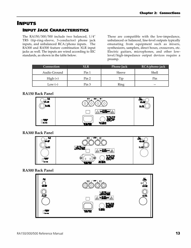
INPUTSINPUT JACK CHARACTERISTICSThe RA150/300/500 include two balanced, 1/4"TRS (tip-ring-sleeve, 3-conductor) phone jackinputs, and unbalanced RCA/phono inputs. TheRA300 and RA500 feature combination XLR inputjacks as well. The inputs are wired according to IECstandards, as shown in the table below.
These are compatible with the low-impedance,unbalanced or balanced, line-level outputs typicallyemanating from equipment such as mixers,synthesizers, samplers, direct boxes, crossovers, etc.Electric guitars, microphones, and other low-level/high-impedance output devices require apreamp.
Connection XLR Phone Jack RCA/phono jack
Audio Ground Pin 1 Sleeve Shell
High (+) Pin 2 Tip Pin
Low (–) Pin 3 Ring --
RA150 Back Panel
RA300 Back Panel
RA500 Back Panel
Connections: Chapter 2
14 RA150/300/500 Reference Manual
Warning: Be sure that the AC power is off priorto connecting or disconnecting any signalwiring.
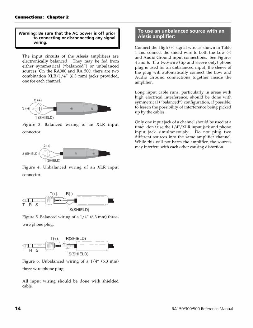
The input circuits of the Alesis amplifiers areelectronically balanced. They may be fed fromeither symmetrical (“balanced”) or unbalancedsources. On the RA300 and RA 500, there are twocombination XLR/1/4” (6.3 mm) jacks provided,one for each channel.
Figure 3. Balanced wiring of an XLR input
connector.
Figure 4. Unbalanced wiring of an XLR input
connector.
Figure 5. Balanced wiring of a 1/4” (6.3 mm) three-
wire phone plug.
Figure 6. Unbalanced wiring of a 1/4” (6.3 mm)
three-wire phone plug
All input wiring should be done with shieldedcable.
To use an unbalanced source with anAlesis amplifier:
Connect the High (+) signal wire as shown in Table1 and connect the shield wire to both the Low (–)and Audio Ground input connections. See Figures4 and 6. If a two-wire (tip and sleeve only) phoneplug is used for an unbalanced input, the sleeve ofthe plug will automatically connect the Low andAudio Ground connections together inside theamplifier.
Long input cable runs, particularly in areas withhigh electrical interference, should be done withsymmetrical (“balanced”) configuration, if possible,to lessen the possibility of interference being pickedup by the cables.
Only one input jack of a channel should be used at atime: don't use the 1/4"/XLR input jack and phonoinput jack simultaneously. Do not plug twodifferent sources into the same amplifier channel.While this will not harm the amplifier, the sourcesmay interfere with each other causing distortion.
Chapter 2: Connections
RA150/300/500 Reference Manual 15
CABLESUse only high quality cables when interfacingequipment with the RA150/300/500. These shouldbe good quality shielded cables with a stranded (notsolid) internal conductor. Although quality cablescost more, they do make a difference. Route cablesto the RA150/300/500 correctly by observing thefollowing precautions.
• Do not bundle audio cables with AC powercords.
• Avoid running audio cables near sources ofelectromagnetic interference such astransformers, monitors, computers, etc.
• Do not place cables where they can be steppedon. Although stepping on a cable may not causeimmediate damage, it can compress theinsulation between the center conductor andshield (thus degrading performance) or reducethe cable’s reliability.
• Avoid twisting the cable or having it makesharp, right angle turns.
• Never unplug a cable by pulling on the wireitself. Always unplug by firmly grasping thebody of the plug and pulling directly outward.If you experience difficulty in removing theplug, sometimes a slight rotating motion whileunplugging will solve the problem.
• Keep the cable contacts clean at all time.Oxidation may lead to intermittent contacts,degraded sound quality, or even distortion. DONOT USE AN ABRASIVE TO CLEAN A DIRTYPLUG. This may remove some of the plug’sconductive plating. Instead, spray contactcleaner on a clean, lint-free cloth and vigorouslyrub the plug until the oxidation is removed.
• Although Alesis does not endorse any specificproduct, chemicals such as Tweek andCramolin, when applied to electrical connectors,are claimed to improve the electrical contactbetween connectors.
• NEVER PLUG OR UNPLUG INPUT CABLESUNLESS THE RA150/300/500 IS TURNEDOFF, UNPLUGGED FROM THE AC LINE, ORHAS THE CHANNEL 1 AND CHANNEL 2LEVEL CONTROLS TURNED TO MINIMUMLEVEL. Failure to observe these precautionsmay result in damage to your speakers if thecable being plugged into the RA150/300/500 iscarrying a signal, and the level is turned up.
CABLE WIRING TIPSIf you decide to wire your own cables, Alesisrecommends that you use three-conductor shieldedcable (even in an installation that uses unbalancedwiring) with either a braided or foil-type shield.Connect one conductor to the phone jack tipconnection to carry the hot signal, and the shieldconnection to the sleeve. The other conductorshould also connect to the shield since it is not goodpractice to depend on the shield wire itself tocomplete the signal connection. This is because theshield wires are more subject to breakage, especiallyin portable installations, than the more protectedinternal insulated wires. By using a second “safety”conductor for ground, the worst that could happenwith a broken shield would be a rise in noise orhum due to the lack of shielding. If the groundconnection were completely lost, there would beeither extremely loud hum or major loss of audio.
Connections: Chapter 2
16 RA150/300/500 Reference Manual
BALANCED OR UNBALANCED?With long cable runs (e.g., over 6 meters/20 feet) innoisy electrical environments, the cable itself can actas an “antenna” and pick up RF fields, AC hum, orother types of interference. To avoid theseproblems, many professional studios and live soundcompanies use balanced line connections. Theaverage application will probably not requirebalanced lines , but using balanced connectorsbetween the mixer and the RA150/300/500 meansone less possibility for ground loops and humelsewhere in the system.
Balanced lines carry a pair of signals, each out ofphase with respect to the other but otherwiseidentical. To be converted back into a single,unbalanced line, both balanced lines feed adifferential amplifier input or transformer thatresponds to the difference in levels between signals.Thus, the out-of-phase signals are recombined intoan unbalanced signal, but interference induced intothe cable will not be out of phase. Since there is nodifference between these signals, the differentialamplifier or transformer will reject the interferenceto a great degree. This tendency to ignoreinterference is called Common Mode Rejection.
To connect a balanced line output tofeed the RA150/300/500:
You have two options:
TRS-to-TRS cableMost modern mixing consoles, such as the AlesisStudio 32, feature balanced outputs on 1/4" TRSjacks. This is the same balancing connector used bythe RA150/300/500. Get a 3-conductor cable with a1/4" male TRS connector at each end.
XLR-to-XLR cableA slightly more expensive balanced connector is theXLR type, most commonly sold as a "microphonecable". The main advantage of this is that theconnector locks in place, making it more resistant toaccidental disconnection. If your mixing consolehas XLR outputs, and you have the RA300 or RA500amplifier, you may connect it with an XLR female toXLR male cable. (The mixer will have an XLR malejack, the amp has an XLR female jack.)
If you have the RA150, which doesn't have an XLRinput, you may use an XLR-F to TRS-M cableor adapter. The 1/4" input jack of the RA150 isbalanced. (See Figure 5 on page 17.)
To connect an unbalanced source tothe amplifier input:
Unbalanced cableSimply use a standard, shielded 1/4" patch cord.Or, if the source has an RCA/phono output, use ashielded phono-to-phono cable.
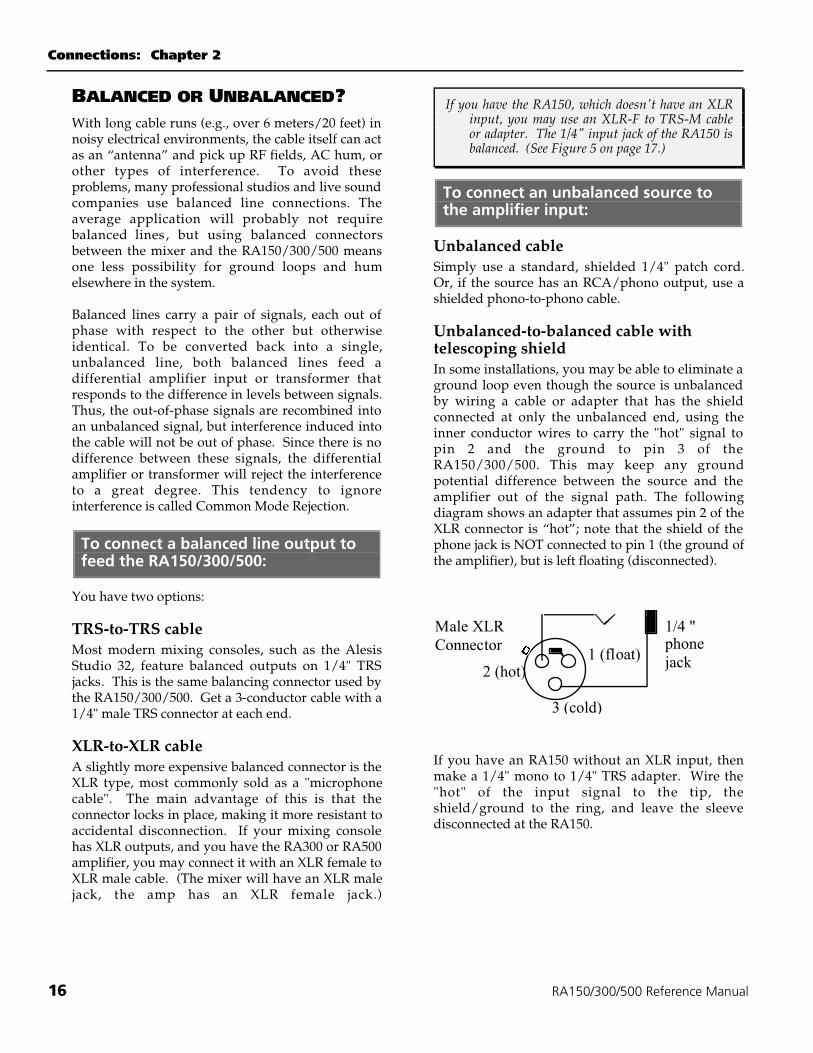
Unbalanced-to-balanced cable withtelescoping shieldIn some installations, you may be able to eliminate aground loop even though the source is unbalancedby wiring a cable or adapter that has the shieldconnected at only the unbalanced end, using theinner conductor wires to carry the "hot" signal topin 2 and the ground to pin 3 of theRA150/300/500. This may keep any groundpotential difference between the source and theamplifier out of the signal path. The followingdiagram shows an adapter that assumes pin 2 of theXLR connector is “hot”; note that the shield of thephone jack is NOT connected to pin 1 (the ground ofthe amplifier), but is left floating (disconnected).
1 (float)2 (hot)
3 (cold)
Male XLRConnector
1/4 "phonejack
If you have an RA150 without an XLR input, thenmake a 1/4" mono to 1/4" TRS adapter. Wire the"hot" of the input signal to the tip, theshield/ground to the ring, and leave the sleevedisconnected at the RA150.
Chapter 2: Connections
RA150/300/500 Reference Manual 17
Isolation transformer or direct boxIf your mixer or other sound source doesn't have abalanced output, you may turn it into a balancedsignal with an external device, either active(electronic, powered) or passive (a transformer).These commonly available audio accessories have abalanced line output, usually in the form of an XLRconnector, and an unbalanced line input, usually inthe form of a 1/4" phone jack.
A line transformer can also convert balancedsignals to unbalanced signals. Advantage of atransformer: High signal carrying capacity, no powerrequired, generates no hiss. Disadvantages:Inexpensive transformers may color the sound dueto frequency response irregularities and can pick uphum due to inductive nature of transformers. Veryhigh-fidelity models are expensive.
Active direct boxes use an active electronic circuitto drive a balanced line, but does not work in theother direction. Advantages: Good frequencyresponse specs, no inherent hum pickup, lessexpensive than transformers. Disadvantages:Requires power, generates some noise.
To feed the same source to severaldifferent amplifiers:
The input impedance of the Alesis amplifiers is 20k! in balanced and 10 k! in unbalancedconfiguration. Thus, the inputs of several amplifiersmay be connected in parallel if desired. Themaximum number of amplifier channels willdepend on the minimum output load impedance ofthe device feeding the amplifiers. For example, ifthe minimum output load impedance of the sourcedevice is 600 !, up to 30 amplifier channels may beconnected to it in parallel without overloading thesource device’s output.
However, use of a distribution amplifier isrecommended in large systems.
To use the amplifier in Bridged Monomode:
Connect the input signal to Channel A/Left only.Move the recessed slide switch under the rightinput connectors to the Bridged Mono position. Donot connect any signal to the Channel B/Rightinput jack. Leave the input level control forChannel B down. See page 20 for output wiring inBridged Mono configuration.
Connections: Chapter 2
18 RA150/300/500 Reference Manual
OUTPUTS
Warning: Be sure that the AC power is off priorto connecting or disconnecting any signalwiring.
WHAT'S THE LOAD IMPEDANCE?Alesis amplifiers can reliably drive 4 ! loads inStereo mode and 8 ! loads in Bridged Mono mode.However, the impedance of a loudspeaker varieswith frequency, and its nominal rated impedance isnot necessarily its minimum impedance. Someloudspeakers carry both nominal and minimumimpedance specifications, and some are suppliedwith impedance curves. When connecting multipleloudspeakers or systems to any amplifier, careshould be taken that the actual load impedance doesnot drop below the amplifier’s rated output load.The RA150/300/500 amplifiers will not be damagedby excessively low output load impedances, butthey will not be able to provide full output powerand their protection circuits may automatically cutoff their outputs until the low load condition isremoved.
CONNECTORSEach channel features a standard binding postconnector (red = “hot” output, black = ground).The binding post or "banana" connectors are thepreferred choice for permanent installations. Thereis greater surface area contact than with phoneconnectors, thus promoting a better electricalconnection between the speaker wire and amplifier.
SPEAKER CABLESThe cables you use between the RA150/300/500and its speakers are very important. Speaker cablesmust deliver large amounts of peak current to aspeaker. To complicate matters further, a speakerrepresents an inductive load, and is more difficult todrive than a purely resistive load. Speakers are alsovery low impedance devices. Any resistancebetween the amp output and speakers will degradethe damping factor, efficiency and ultimately, thesound quality.
Alesis recommends stranded, rather than solid,cables for flexibility and ease of installation.However, solid cables are equally usable.
Never use shielded guitar cords as speaker cables.Because they lack sufficient current-carryingcapacity, the amp and speakers will not performproperly and the sound may be degraded.
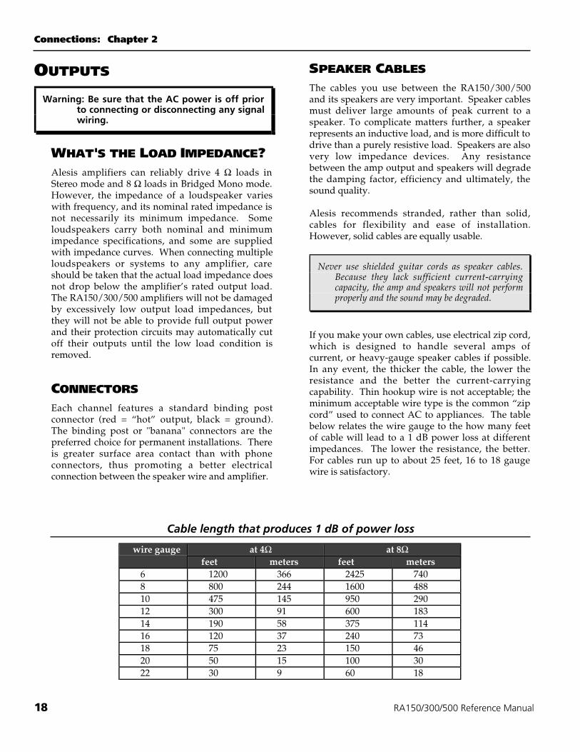
If you make your own cables, use electrical zip cord,which is designed to handle several amps ofcurrent, or heavy-gauge speaker cables if possible.In any event, the thicker the cable, the lower theresistance and the better the current-carryingcapability. Thin hookup wire is not acceptable; theminimum acceptable wire type is the common “zipcord” used to connect AC to appliances. The tablebelow relates the wire gauge to the how many feetof cable will lead to a 1 dB power loss at differentimpedances. The lower the resistance, the better.For cables run up to about 25 feet, 16 to 18 gaugewire is satisfactory.
Cable length that produces 1 dB of power loss
at 4! at 8!wire gaugefeet meters feet meters
6 1200 366 2425 7408 800 244 1600 48810 475 145 950 29012 300 91 600 18314 190 58 375 11416 120 37 240 7318 75 23 150 4620 50 15 100 3022 30 9 60 18
Chapter 2: Connections
RA150/300/500 Reference Manual 19
In recent years, expensive audiophile cables of highcurrent capacity have appeared. These have beensomewhat controversial; some feel the extra expenseproduces an audible improvement in sound quality,while others find no sonic difference betweenaudiophile cables and other heavy-duty wiring.While Alesis does not endorse any particular brandof cable, we suggest that you investigate differentcable types for yourself to discover if they improvethe sound of your particular setup.
CONNECTING SPEAKER CABLESTO BINDING POSTSThe RA150/300/500 connectors are perfect forstudio installations, especially near field monitorusage, where an effective and reliable connector isrequired. In addition, these connectors are veryeasy to set up in several different ways.
To connect speaker cable to theconnectors:
1. Remove approximately 1/4" of insulation fromthe ends of the wires, being careful not to nickany of the strands.
2 . Twist the strands together. Unscrew thespeaker terminals on the amplifier.
3. Feed the strands through the exposed hole inthe binding posts, with the negative connectedto the black terminal and the positive to the redterminal. Be careful that:
• The connector clamps down on the strands,not the insulation
• No stray strands contact any part of thechassis other than the connector.
4. Tighten down the binding posts and check thatthe wires can't be pulled out.
Tip: It may be easier to attach the speaker wiresbefore the amplifier is mounted into a rack.
Using a banana plug:Standard "dual banana plugs" (such as Pomona typeMDP) should be used if the speaker cable will beremoved from the amplifier often (for example,when used in a portable PA system).
In this case, simply:
1. Loosen the setscrews in the shaft of the pluguntil there is enough room to insert the wires ineach side of the connector. (But be careful thatthe setscrew doesn't fall out.)
2. Remove approximately 1/4" of insulation fromthe ends of the wires, being careful not to nickany of the strands.
3. Determine the + and – conductors of the cable(by markings or moldings on the wire, or by thecolor of wire or insulation). Push the "-" sideinto the opening in the side of the connectormarked "GND" or with a ridge sticking out theside.
4. Using a small screwdriver, tighten the setscrewagainst the wire.
5. Push the other "+" wire through the strain reliefand into the other opening, and tighten it aswell.
When plugging the banana plug into the amplifier,make sure that:
• The red and black wire nuts in the amplifierhave been screwed down first.
• The side of the banana connector with theridge or nub is plugged into the blackconnector.
Using a crimp-on connector:If a crimp lug terminal is used on the speaker wireand the lug is too small to fit onto the threaded post,one leg of the terminal may be inserted in the holein the post. As with wire connections, make certainthat the terminal is snugly attached by tighteningthe plastic insulator nut.
Connections: Chapter 2
20 RA150/300/500 Reference Manual
THE IMPORTANCE OF SPEAKERPOLARITYThe speaker cone’s motion should mimic theinstrument it’s reproducing. For example, a kickdrum pushes air toward you on the initial transient,so a speaker reproducing a kick drum should haveits cone push air toward you. If the polarity isreversed, the cone will suck air away from you.Even though the same amount of air is moved ineither case, many listeners report superior soundwith proper polarity as opposed to reversedpolarity.
An additional problem occurs if the polarity of onespeaker is reversed with respect to the other. Thiscan cause phase-related problems such as thin bass,poor stereo imaging and frequency responseanomalies.
With the RA150/300/500, polarity is a function ofcorrectly hooking up the output cables. Usually, forproper polarity, the tip of the output phone plug orthe red terminal of the output connector mustconnect to the speaker’s positive (+) terminal. Thiswill ensure that polarity from the RA150/300/500input to speaker cone motion will be consistent.Check your speakers' polarity, however, becausenot all brands follow this wiring convention.
Please note that polarity reversal can occur indevices (such as mixers or effects units) “upstream”of the RA150/300/500. To test for proper speakerand system polarity, see page 22.
OUTPUT CONNECTIONS FORBRIDGED OPERATIONInstead of using the RA150/300/500 as a stereo 2-channel amplifier, it is possible to use it as a monoamplifier with twice the power. This uses bothsides of the amplifier in a push-pull configuration,so the speaker must be wired to the amp differently.
However, note that the minimum load impedance is8 ohms, instead of the 4 ohms in stereo operation.
To connect a speaker in bridged monomode:
Following the instructions on the previous page forbinding post or crimp-on connection, connect the"+" wire to the red binding post for the Channel1/Left and the "-" wire to the red binding post forChannel 2/Right.
You may use a dual banana plug in this situation. Ifpresent, remove the protective caps from the top ofthe binding posts for the two red terminals. Plugthe banana connector into the two center redterminals with the ridged/GND side on Channel2/Right.
The single input is connected ONLY to the Channel1/Left input jack, and the stereo/mono switchunder the right input connector should be set toBRIDGED MONO. Don't plug any input into theChannel 2/Right input jack, and leave the Channel2 volume control all the way down.
Should you use bridged mode?
In a typical PA system with two speakers, in mostcases you'll be better off running theRA150/300/500 in stereo mode, because mostspeakers are 8 ohms and if they were wired inparallel the total load would be 4 ohms, too low forbridged mode. In any case, the total system volumedoesn't rise if you were to connect 2 speakers to asingle 500-watt amp instead of to two 250-wattamps.
But if you are connecting to a single speaker (suchas a subwoofer) in a biamped or triamped setup,bridged mono mode will give you the chest-thumping headroom you need.
Chapter 3: Operation
RA150/300/500 Reference Manual 21
CHAPTER 3
OPERATIONFRONT PANEL CONTROLS
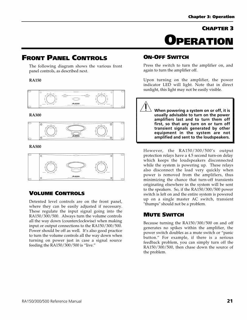
The following diagram shows the various frontpanel controls, as described next.
RA150
RA300
RA500
VOLUME CONTROLSDetented level controls are on the front panel,where they can be easily adjusted if necessary.These regulate the input signal going into theRA150/300/500. Always turn the volume controlsall the way down (counterclockwise) when makinginput or output connections to the RA150/300/500.Power should be off as well. It’s also good practiceto turn the volume controls all the way down whenturning on power just in case a signal sourcefeeding the RA150/300/500 is “live.”
ON-OFF SWITCHPress the switch to turn the amplifier on, andagain to turn the amplifier off.
Upon turning on the amplifier, the powerindicator LED will light. Note that in directsunlight, this light may not be easily visible.
When powering a system on or off, it isusually advisable to turn on the poweramplifiers last and to turn them offfirst, so that any turn on or turn offtransient signals generated by otherequipment in the system are notamplified and sent to the loudspeakers.
However, the RA150/300/500’s outputprotection relays have a 4.5 second turn-on delaywhich keeps the loudspeakers disconnectedwhile the system is powering up. These relaysalso disconnect the load very quickly whenpower is removed from the amplifiers, thusminimizing the chance that turn-off transientsoriginating elsewhere in the system will be sentto the speakers. So, if the RA150/300/500 powerswitch is left on and the entire system is poweredup on a single master AC switch, transient"thumps" should not be a problem.
MUTE SWITCHBecause turning the RA150/300/500 on and offgenerates no spikes within the amplifier, thepower switch doubles as a mute switch or “panicbutton.” For example, if there is a seriousfeedback problem, you can simply turn off theRA150/300/500, then chase down the source ofthe problem.
Operation: Chapter 3
22 RA150/300/500 Reference Manual
PROTECT/CLIP INDICATORSClip lights for each channel indicate the onset ofactual clipping. Even if the problem occurs for onlya few microseconds, a pulse-stretching circuit willallow the LED to light long enough for you to seethat a problem is occurring.
Because of the RA150/300/500’s ability to enterand exit clipping with as few audible artifacts aspossible, you may not hear any distortion even ifthe indicator flashes. In general, a few flashes everynow and then will not be a problem. However, ifthe LEDs flash often or remain on for any extendedperiod of time, then turn down the volume controlsto reduce the signal level going to theRA150/300/500. If this doesn’t solve the problem,check your output cables and speakers.
METERS (RA300 AND RA500ONLY)In the center of the front panel are two meters thatshow the total power output of each channel. Thehighest (red) LED indicates the unit is at maximumoutput, at the onset of clipping. The orangePROTECT LEDs come on when the unit is 6 dBbelow rated output. Operation with the PROTECTLED on continuously will lead to amplifieroverheating and eventual thermal shutdown toprotect the circuitry. The two green LEDs closest tothe PROTECT LED will actually light at higherlevels than –6 dB, but before clipping. Lower greenLEDs indicate signal in a normal operating range.No LEDs will light if the amplifier is operating 33dB or less below maximum rated output.
The PROTECT LEDs will light in two other cases:
• For 4.5 seconds at initial turn-on while theoutput relay is connected.
• When the thermal protection circuitry isactivated because the amplifier isoverheating. Thermal protection will stopautomatically when the amplifier coolsdown.
BACK PANEL CONTROLSAC VOLTAGE SWITCHLocated near the power inlet is a recessed switchthat allows voltage conversion from 120 volt to230 volt operation. Use a small tool or pen tochange the setting of this switch only if it is set tothe wrong value for the country the amplifier willbe used in.
When changing voltages the fuse must bechanged to the correct rating as shownon page 10.
STEREO/BRIDGED MONO SWITCHUnderneath the right input jack, this switchconverts the RA150/300/500 from its normaloperation as a two-channel amplifier to operationas a single-channel amplifier with approximatelytwice the power. Make sure this switch is setproperly for your application. See page 20.
If this switch is accidentally switched to Monowhile wired for stereo, you will hearout-of-phase audio as the Channel2/Right control is turned up.
CHECKING FOR PROPERPOLARITY
To check for correct speaker polarity, brieflyconnect the + terminal of a 1.5V battery to thespeaker cable’s “hot” or + lead, and the battery’s- terminal to the speaker cable’s “cold,” ground,or - lead. You will hear a “pop” from theloudspeaker as you connect the battery, andanother as you disconnect it. Observe thedirection of the speaker cone movement. If thespeaker cables are wired in the common manner(and the speakers themselves are notmislabelled), the speaker cone will move forward(toward you) when you connect the battery andaway from you when the battery is disconnected.
If the speaker cone moves in the oppositedirection, reverse the wires going to the speakerand re-test for proper polarity. Always checkyour speakers' polarity as not all manufacturersfollow the same wiring convention.
Chapter 3: Operation
RA150/300/500 Reference Manual 23
USING THE RA150 AS AHEADPHONE AMPLIFIER
The RA150 is particularly suited for use drivinghigh-impedance headphones in studio applica-tions. However, the power is considerably greaterthan that provided by most "headphoneamplifiers", which are often rated at 1 watt orbelow.
Due to the high efficiency of headphonesand the power of the amplifier, serioushearing damage may result from misuseof this product. Exercise cautionregarding sound levels.
Keep the following in mind:
• Many studio-quality headphones featureimpedances of 600 ohms or greater. Thismeans that many headphones of the sametype may be plugged in parallel to theoutput of the RA150/300/500 before the 4-ohm limit is reached.
• If you plug in a headphone with a lower 8-ohm impedance, it will be dramaticallyhigher in level than the others, and thehigh-impedance headphones may drop toinaudibility.
• The TRS 1/4" jack used in headphones willtie together the grounds of the left andright amplifier channels. Use caution andonly connect or disconnect head-phoneswhen the amplifier is powered off.
• Keep the RA150's front panel volumecontrols at a very low level and the controlsof the headphone send near maximum.This will prevent accidental "blasting"during a session.
CHOOSING THE CORRECTSPEAKERS
Near-field monitoring through “reference”speakers has become the preferred way tomonitor and mix music. With near-fieldmonitoring, small speakers are placed so thatthey are a few feet from the engineer’s ears. As aresult, room acoustics become less importantsince the primary acoustic interaction involvesdirect sound from the speakers rather thanreflected sounds from the room. Since few homeand project studios have good acoustics, near-field monitors can provide realistic monitoring ina small space at relatively low levels.
Near-field monitors offer other advantagescompared to large studio speakers, includingsmaller size, lower cost, and easiertransportability to other studios for referencepurpose.
Because of its moderate power rating, excellentfidelity, and lack of a noise-generating fan, theRA150/300/500 “Reference Amplifier” excels indriving reference near-field monitor speakers insmaller studios. However, you should choosespeakers that can handle the power theRA150/300/500 can generate. Speaker wattageratings are often confusing, and standards bywhich ratings are obtained vary frommanufacturer to manufacturer. If a speaker canhandle 100 watts RMS continuous power, itshould be able to handle the RA150/300/500.However, under conditions of clipping or otherabuse of the RA150/300/500, damage to speakersis possible. For best results, use speakersdesigned for medium- to high-powerapplications.
Operation: Chapter 3
24 RA150/300/500 Reference Manual
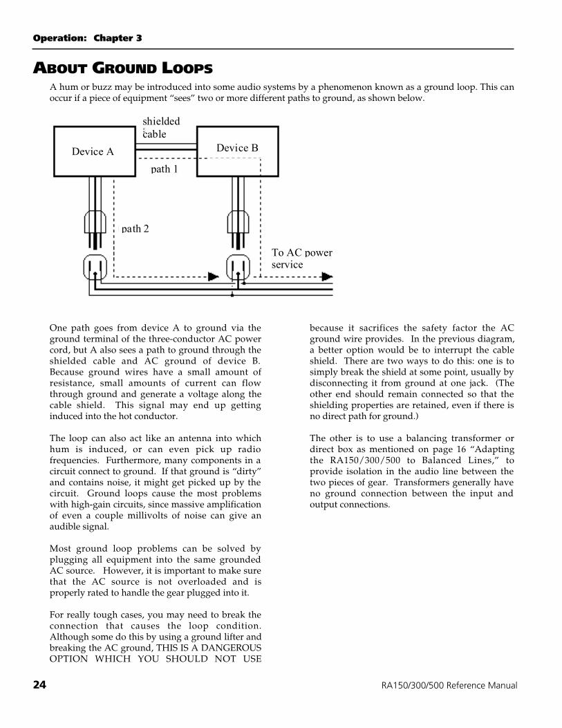
ABOUT GROUND LOOPSA hum or buzz may be introduced into some audio systems by a phenomenon known as a ground loop. This canoccur if a piece of equipment “sees” two or more different paths to ground, as shown below.
Device A Device B
shieldedcable
path 2
path 1
To AC powerservice
One path goes from device A to ground via theground terminal of the three-conductor AC powercord, but A also sees a path to ground through theshielded cable and AC ground of device B.Because ground wires have a small amount ofresistance, small amounts of current can flowthrough ground and generate a voltage along thecable shield. This signal may end up gettinginduced into the hot conductor.
The loop can also act like an antenna into whichhum is induced, or can even pick up radiofrequencies. Furthermore, many components in acircuit connect to ground. If that ground is “dirty”and contains noise, it might get picked up by thecircuit. Ground loops cause the most problemswith high-gain circuits, since massive amplificationof even a couple millivolts of noise can give anaudible signal.
Most ground loop problems can be solved byplugging all equipment into the same groundedAC source. However, it is important to make surethat the AC source is not overloaded and isproperly rated to handle the gear plugged into it.
For really tough cases, you may need to break theconnection that causes the loop condition.Although some do this by using a ground lifter andbreaking the AC ground, THIS IS A DANGEROUSOPTION WHICH YOU SHOULD NOT USE
because it sacrifices the safety factor the ACground wire provides. In the previous diagram,a better option would be to interrupt the cableshield. There are two ways to do this: one is tosimply break the shield at some point, usually bydisconnecting it from ground at one jack. (Theother end should remain connected so that theshielding properties are retained, even if there isno direct path for ground.)
The other is to use a balancing transformer ordirect box as mentioned on page 16 “Adaptingthe RA150/300/500 to Balanced Lines,” toprovide isolation in the audio line between thetwo pieces of gear. Transformers generally haveno ground connection between the input andoutput connections.
Chapter 3: Operation
RA150/300/500 Reference Manual 25
SYSTEM SETUP AND TESTINGBefore applying power for the first time, doublecheck the wiring to insure that everything is firmlyconnected and that the proper signals are being fedto the proper places. If a low frequency signal in amulti-amplified system is applied to a highfrequency transducer, the transducer can bedamaged, and a loose connection can cause noisewhich can damage any transducer.
Be certain that the amplifier front panel gaincontrols are set to minimum when the systemunder test is first powered up. After the power isapplied, slowly advance each gain control toconfirm that there are no driver-destroying humsor buzzes present—if there are, turn the power offand locate the source of the difficulty.
When first applying program material to thesystem, it is also advisable to keep the gain controlsturned down to confirm, once again, that thewiring is correct. Once the system wiring isdetermined to be correct, the gain controls can thenbe set to an appropriate level for the system gainstructure.
SETTING THE GAIN PROPERLYSetting the system gain is fairly straightforward,but if it is not properly adjusted, the system’sdistortion and noise characteristics may be lessthan optimum.
The most common cause of noisy operation,especially in studio use, is that the amplifier'sgain controls are left all the way up, while themixer's output is turned down. This can leadto blown speakers if the mixer is accidentallyturned up, but more importantly, it amplifiesthe noise floor of the mixer output stage orwiring unnecessarily. Keeping the sourcelevel as high as possible and lowering theamplifier input gain will keep the noise levelat a minimum.
The input sensitivity of the RA150/300/500amplifiers at the 1/4" input or XLR input is1.23 volts (+4 dBu) for rated output with theamplifier gain controls at maximum. If you'replugged into the phono jacks, the sensitivity is–10 dBV (.316 volts). If the signal at the amplifierinput is higher than this, the input gain controlsof the RA150/300/500 must be turned down toavoid amplifier clipping. Most mixers output +4dBu at nominal level/0 VU; that means if you go"into the yellow" on the meter of most mixers, theamp will be clipping its outputs or distorting thespeakers unless you turn down the input gaincontrols.
It is generally best to try to keep the gain of thesource device set for best signal-to-noise ratioconsistent with distortion, and to then set theamplifier inputs for the desired SPL level.
A good way to set levels is to use a test tone orpink noise with a sound level meter. Set themixer's controls at nominal levels, increasethe test tone until the mixer is exercising itsdynamic range without clipping itself. Themixer's meter should read from +10 to +15.Then slowly raise the RA150/300/500's inputlevel controls until the desired peak soundpressure level is achieved.
Operation: Chapter 3
26 RA150/300/500 Reference Manual
Amplifier input clippingOn the other hand, the maximum level at theamplifier’s input terminals is +26 dBu, regardlessof the setting of the channel input level controls. Itis possible that the output signal from the sourcemay be too high and, thus, distorted before itreaches the amplifier gain control, either becausethe source device is clipping or the amplifier inputstage is overloaded. In either case, no amount oflevel control adjustment at the amplifier canremove this distortion, and you should lower theoutput level of the device feeding the amplifieruntil the distortion stops.
OUTPUT RELAYS/THERMALCYCLINGReference Series amplifiers have high-currentoutput protection relays which disconnect theoutput in the event of overheating, DC offset,audio signals below 5 Hz on the output terminalsor excessively low line voltage. When thishappens in the RA300/500, the PROTECTindicators of both channels will glow. Additionalprotection circuitry keeps RFI out of the audiocircuits, assuring clean, stable operation indifficult environmental conditions.
If the unit shuts off, turn off the power and checkfor problems with the wiring, input level, orventilation of the amplifier.
Continued high-temperature operation may alsotrigger an internal thermal fuse, which will shutthe unit off entirely until it has cooled off. In thiscase, the PROTECT indicators and POWERindicators will turn off as well.
Overheating is the most common cause ofamplifier shutdown. You must ensure thatthe heat sinks of the amplifier are not blockedand can receive a supply of cooler air.
Chapter 4: Troubleshooting
RA150/300/500 Reference Manual 27
CHAPTER 4
TROUBLESHOOTINGTROUBLESHOOTING INDEX
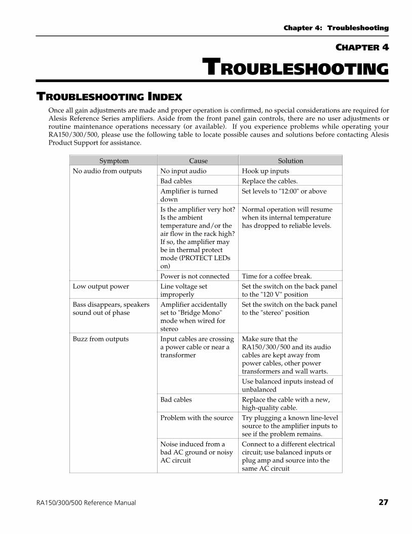
Once all gain adjustments are made and proper operation is confirmed, no special considerations are required forAlesis Reference Series amplifiers. Aside from the front panel gain controls, there are no user adjustments orroutine maintenance operations necessary (or available). If you experience problems while operating yourRA150/300/500, please use the following table to locate possible causes and solutions before contacting AlesisProduct Support for assistance.
Symptom Cause SolutionNo audio from outputs No input audio Hook up inputs
Bad cables Replace the cables.Amplifier is turneddown
Set levels to "12:00" or above
Is the amplifier very hot?Is the ambienttemperature and/or theair flow in the rack high?If so, the amplifier maybe in thermal protectmode (PROTECT LEDson)
Normal operation will resumewhen its internal temperaturehas dropped to reliable levels.
Power is not connected Time for a coffee break.Low output power Line voltage set
improperlySet the switch on the back panelto the "120 V" position
Bass disappears, speakerssound out of phase
Amplifier accidentallyset to "Bridge Mono"mode when wired forstereo
Set the switch on the back panelto the "stereo" position
Make sure that theRA150/300/500 and its audiocables are kept away frompower cables, other powertransformers and wall warts.
Buzz from outputs Input cables are crossinga power cable or near atransformer
Use balanced inputs instead ofunbalanced
Bad cables Replace the cable with a new,high-quality cable.
Problem with the source Try plugging a known line-levelsource to the amplifier inputs tosee if the problem remains.
Noise induced from abad AC ground or noisyAC circuit
Connect to a different electricalcircuit; use balanced inputs orplug amp and source into thesame AC circuit
Troubleshooting: Chapter 4
28 RA150/300/500 Reference Manual
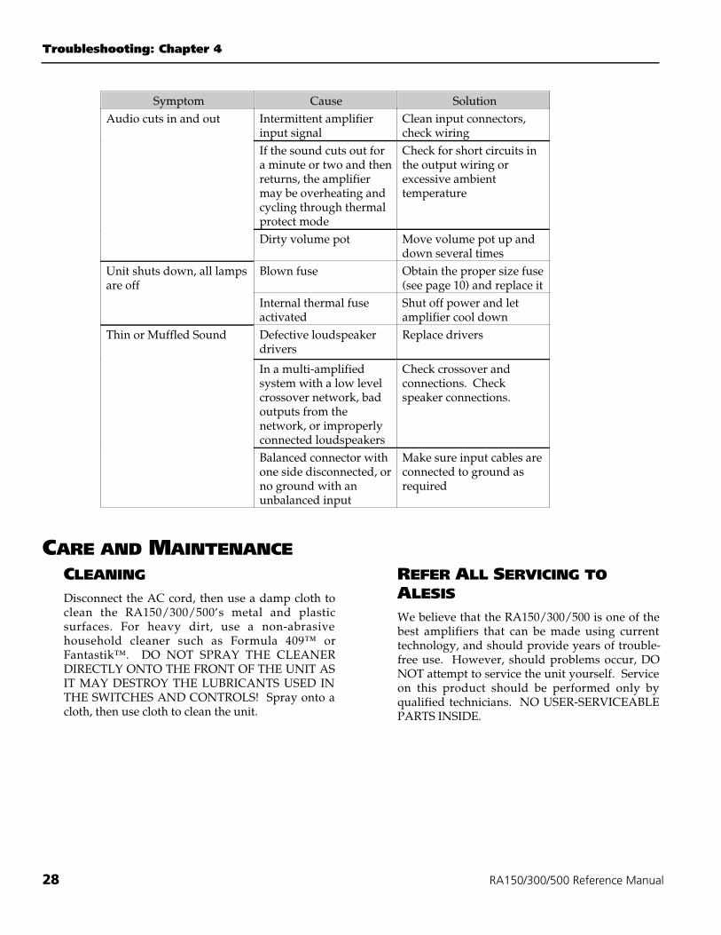
Symptom Cause SolutionIntermittent amplifierinput signal
Clean input connectors,check wiring
If the sound cuts out fora minute or two and thenreturns, the amplifiermay be overheating andcycling through thermalprotect mode
Check for short circuits inthe output wiring orexcessive ambienttemperature
Audio cuts in and out
Dirty volume pot Move volume pot up anddown several times
Blown fuse Obtain the proper size fuse(see page 10) and replace it
Unit shuts down, all lampsare off
Internal thermal fuseactivated
Shut off power and letamplifier cool down
Defective loudspeakerdrivers
Replace drivers
In a multi-amplifiedsystem with a low levelcrossover network, badoutputs from thenetwork, or improperlyconnected loudspeakers
Check crossover andconnections. Checkspeaker connections.
Thin or Muffled Sound
Balanced connector withone side disconnected, orno ground with anunbalanced input
Make sure input cables areconnected to ground asrequired
CARE AND MAINTENANCECLEANINGDisconnect the AC cord, then use a damp cloth toclean the RA150/300/500’s metal and plasticsurfaces. For heavy dirt, use a non-abrasivehousehold cleaner such as Formula 409™ orFantastik™. DO NOT SPRAY THE CLEANERDIRECTLY ONTO THE FRONT OF THE UNIT ASIT MAY DESTROY THE LUBRICANTS USED INTHE SWITCHES AND CONTROLS! Spray onto acloth, then use cloth to clean the unit.
REFER ALL SERVICING TOALESISWe believe that the RA150/300/500 is one of thebest amplifiers that can be made using currenttechnology, and should provide years of trouble-free use. However, should problems occur, DONOT attempt to service the unit yourself. Serviceon this product should be performed only byqualified technicians. NO USER-SERVICEABLEPARTS INSIDE.
Chapter 4: Troubleshooting
RA150/300/500 Reference Manual 29
OBTAINING REPAIR SERVICEBefore contacting Alesis, check over all yourconnections, and make sure you’ve read themanual.
Customers in the USA and Canada: If the problempersists, contact Alesis USA at www.alesis.com &find the Product Support web page. Makesure you have the unit’s serial number with you.If necessary contact one of our technicians;if appropriate, you will be given a return order (RO)number and instructions on how to return the unit.All units must be shipped prepaid and CODshipments will not be accepted.
For prompt service, indicate the RO number on theshipping label. Units without an RO will not beaccepted. If you do not have the original packing,ship the unit in a sturdy carton, with shock-absorbing materials such as Styrofoam pellets (thekind without CFCs, please) or “bubble-pack”surrounding the unit. Shipping damage caused byinadequate packing is not covered by the Alesiswarranty.
Tape a note to the top of the unit describing theproblem, include your name and a phone numberwhere Alesis can contact you if necessary, as wellas instructions on where you want the productreturned. Alesis will pay for standard one-wayshipping back to you on any repair covered underthe terms of this warranty. Next day service isavailable for a surcharge. Field repairs are notauthorized during the warranty period, and repairattempts by unqualified personnel may invalidatethe warranty.
CUSTOMERS OUTSIDE THE USAAND CANADA:Contact your local Alesis distributor for anywarranty assistance. The Alesis LimitedWarranty applies only to products sold to usersin the USA and Canada. Customers outside ofthe USA and Canada are not covered by thisLimited Warranty and may or may not becovered by an independent distributor warrantyin the country of sale. Do not return products tothe factory unless you have been given specificinstructions to do so.
Internet Address: Important information andadvice is available on our web site:
http://www.alesis.com
Email may be addressed to:
Specifications
30 RA150/300/500 Reference Manual
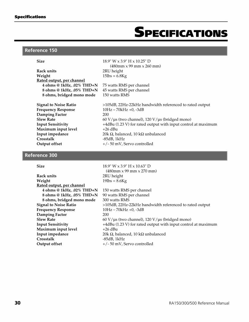
SPECIFICATIONSReference 150
Size 18.9" W x 3.9" H x 10.25" D(480mm x 99 mm x 260 mm)
Rack units 2RU heightWeight 15lbs = 6.8KgRated output, per channel
4 ohms @ 1kHz, .02% THD+N 75 watts RMS per channel8 ohms @ 1kHz, .05% THD+N 45 watts RMS per channel8 ohms, bridged mono mode 150 watts RMS
Signal to Noise Ratio >105dB, 22Hz-22kHz bandwidth referenced to rated outputFrequency Response 10Hz – 70kHz +0, -3dBDamping Factor 200Slew Rate 60 V/µs (two channel), 120 V/µs (bridged mono)Input Sensitivity +4dBu (1.23 V) for rated output with input control at maximumMaximum input level +26 dBuInput impedance 20k !, balanced, 10 k! unbalancedCrosstalk -85dB, 1kHzOutput offset +/- 50 mV, Servo controlled
Reference 300
Size 18.9" W x 3.9" H x 10.63" D (480mm x 99 mm x 270 mm)
Rack units 2RU heightWeight 19lbs = 8.6KgRated output, per channel
4 ohms @ 1kHz, .02% THD+N 150 watts RMS per channel8 ohms @ 1kHz, .05% THD+N 90 watts RMS per channel8 ohms, bridged mono mode 300 watts RMS
Signal to Noise Ratio >105dB, 22Hz-22kHz bandwidth referenced to rated outputFrequency Response 10Hz – 70kHz +0, -3dBDamping Factor 200Slew Rate 60 V/µs (two channel), 120 V/µs (bridged mono)Input Sensitivity +4dBu (1.23 V) for rated output with input control at maximumMaximum input level +26 dBuInput impedance 20k !, balanced, 10 k! unbalancedCrosstalk -85dB, 1kHzOutput offset +/- 50 mV, Servo controlled
Specifications
RA150/300/500 Reference Manual 31
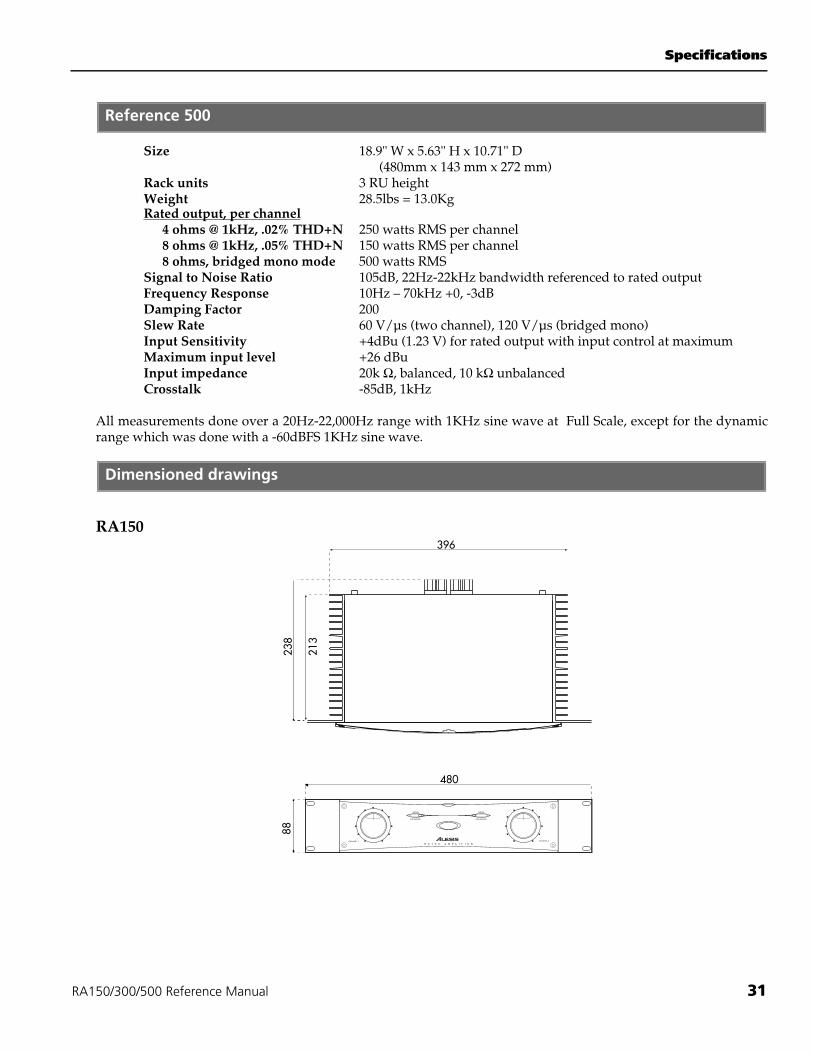
Reference 500
Size 18.9" W x 5.63" H x 10.71" D (480mm x 143 mm x 272 mm)Rack units 3 RU heightWeight 28.5lbs = 13.0KgRated output, per channel
4 ohms @ 1kHz, .02% THD+N 250 watts RMS per channel8 ohms @ 1kHz, .05% THD+N 150 watts RMS per channel8 ohms, bridged mono mode 500 watts RMS
Signal to Noise Ratio 105dB, 22Hz-22kHz bandwidth referenced to rated outputFrequency Response 10Hz – 70kHz +0, -3dBDamping Factor 200Slew Rate 60 V/µs (two channel), 120 V/µs (bridged mono)Input Sensitivity +4dBu (1.23 V) for rated output with input control at maximumMaximum input level +26 dBuInput impedance 20k !, balanced, 10 k! unbalancedCrosstalk -85dB, 1kHz
All measurements done over a 20Hz-22,000Hz range with 1KHz sine wave at Full Scale, except for the dynamicrange which was done with a -60dBFS 1KHz sine wave.
Dimensioned drawings
RA150
Specifications
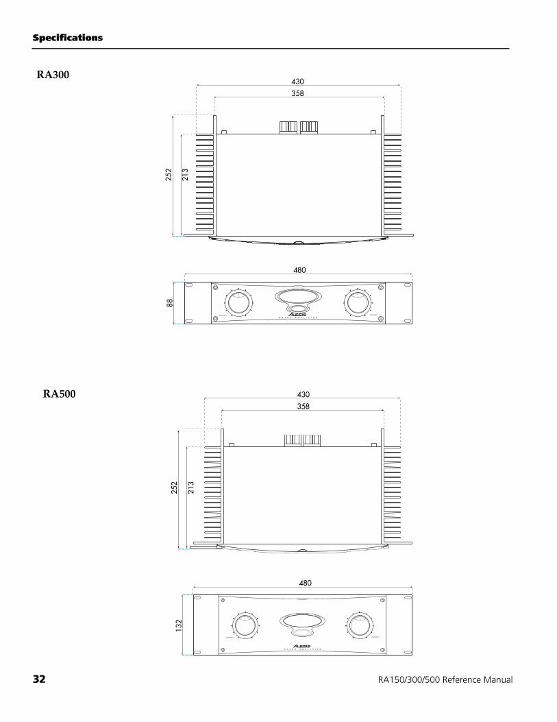
32 RA150/300/500 Reference Manual
RA500
RA300
Specifications
RA150/300/500 Reference Manual 33
Architect's and Engineer's Specifications
The power amplifier shall be a two-channel unitcapable of being switched to single-channelbridged mode operation. All components shall beof high quality and mechanical construction andoptimized for high reliability under adversephysical and electrical conditions. Cooling shall beconvection-type only, with no fan mounted insidethe amplifier.
The inputs shall be differentially balanced withactive current sources for rejection of electro-magnetic interference. The input connectors shallbe 3-conductor 1/4" TRS jacks mounted on the backpanel. Additional unbalanced RCA/ phono inputsshall also be mounted on the back panel. [RA300and RA500: There shall also be provision forfemale XLR input jacks on each channel.]
The output stages of the amplifier shall be a highcurrent, triple darlington type biased for class ABoperation, fully rated for continuous 4 ohmoperation with 2 ohm dynamic stability (stereomode only). An active DC servo circuit is to beemployed to automatically null DC output voltageoffsets. The amplifier shall feature active circuitrythat continuously monitors the output stage forexcessive DC offset, short circuits and thermaloverload. In the event of an output fault, theprotection circuitry will activate the output relayand disconnect the loudspeaker load. This circuitrywill also mute the amplifier during power on/offtransitions.
The power supplies of the amplifier shall utilizeheavy-duty stacked steel EI laminated transformersfor maximum performance and reliability, withhigh current bridge rectifiers, massive secondarycapacitors and current in-rush limiters. An externalvoltage selection switch on the back panel shallallow the user to switch between 120-volt and 230-volt AC power input. A power switch shall beprovided on the front panel with an on/offindicator lamp.
The front panel of the amplifier shall feature twodetented volume controls capable of delivering fullrated power at full clockwise rotation with a +4dBu input, and turning the amplifier down at least70 dB or to silence at full counterclockwise rotation.
The chassis shall be rack mountable in a standard19" EIA equipment rack. Output connectors shallbe two-way binding posts capable of acceptingheavy gauge wire or banana-type connectors.
The power output of the amplifier shall be 75watts per channel (RA150), 150 watts per channel(RA300) or 250 watts per channel (RA500) into a4-ohm load, with no more than .02% totalharmonic distortion. The units shall be capable of150 watts (RA150), 300 watts (RA300), or 500watts (RA500) into an 8-ohm load when operatedin bridged mono mode with no more than .05%total harmonic distortion.
The amplifier shall be an Alesis RA150/300/500Reference Series power amplifier.
Index
34 RA150/300/500 Reference Manual
INDEX
120-volt to 230-volt conversion, 10, 22AC cord, 9AC power, 10balanced inputs, 14balanced lines, 16banana plugs, 19Bridged Mono mode, 17, 20cables
shielded input, 15speaker, 18
class AB, 7, 33cooling, 7, 11direct box, 17Fuse, 10gain setting, 25ground
audio, 9, 14ground lifter, 24ground loop, 24grounding, 3headphone amplifiers, 23heat sink, 11high-temperature operation, 11impedance
input, 17speaker, 18
input clipping, 26Inputs, 13magnetic fields, 12Maintenance, 28Meters, 22Mono. See Bridged Mononoise, 25Output Relays, 26Outputs, 18
phase. See polarityphone plug inputs, 14polarity, 20
how to test, 22power
output, 30Power cable, 3power loss
in speaker cable, 18protection, 7Rack Mounting, 11RCA/phono input jacks. SeeRepair Service, 29Safety, 3, 24shield
telescoping, 24sound level meter, 25Specifications, 30thermal protect mode, 27transformer
input, 17transformers
power, 7, 33TRS jacks, 14, 16turn-on delay, 21unbalanced input, 14, 16Unbalanced-to-balanced cable, 16ungrounded outlets, 9volume controls, 21XLR input, 16XLR input jacks, 13

RA150/300/500 Reference Manual 35
ALESIS LIMITED WARRANTY ALESIS ("ALESIS") warrants this product to be free of defects in material and workmanship for aperiod of one (1) year for parts and for a period of one (1) year for labor from the date of original retail purchase. Thiswarranty is enforceable only by the original retail purchaser and cannot be transferred or assigned.
The purchaser should register thier product online @ www.alesis.com within 14 days of purchase.
During the warranty period ALESIS shall, at its sole and absolute option, either repair or replace free of charge anyproduct that proves to be defective on inspection by ALESIS or its authorized service representative. In all cases disputesconcerning this warranty shall be resolved as prescribed by law.
To obtain warranty service, the purchaser must first call or write ALESIS at the address and telephone number printedbelow to obtain a Return Authorization Number and instructions concerning where to return the unit for service. Allinquiries must be accompanied by a description of the problem. All authorized returns must be sent to ALESIS or anauthorized ALESIS repair facility postage prepaid, insured and properly packaged. Proof of purchase must be presented inthe form of a bill of sale, canceled check or some other positive proof that the product is within the warranty period.ALESIS reserves the right to update any unit returned for repair. ALESIS reserves the right to change or improve design ofthe product at any time without prior notice.
This warranty does not cover claims for damage due to abuse, neglect, alteration or attempted repair by unauthorizedpersonnel, and is limited to failures arising during normal use that are due to defects in material or workmanship in theproduct.
THE ABOVE WARRANTIES ARE IN LIEU OF ANY OTHER WARRANTIES OR REPRESENTATIONS WHETHEREXPRESS OR IMPLIED OR OTHERWISE, WITH RESPECT TO THE PRODUCT, AND SPECIFICALLY EXCLUDE ANYIMPLIED WARRANTIES OF FITNESS FOR A PARTICULAR PURPOSE OR MERCHANTABILITY OR OTHER IMPLIEDWARRANTIES. Some states do not allow limitations on how long an implied warranty lasts, so the above limitation maynot apply to you.
IN NO EVENT WILL ALESIS BE LIABLE FOR INCIDENTAL, CONSEQUENTIAL, INDIRECT OR OTHER DAMAGESRESULTING FROM THE BREACH OF ANY EXPRESS OR IMPLIED WARRANTY, INCLUDING, AMONG OTHERTHINGS, DAMAGE TO PROPERTY, DAMAGE BASED ON INCONVENIENCE OR ON LOSS OF USE OF THEPRODUCT, AND, TO THE EXTENT PERMITTED BY LAW, DAMAGES FOR PERSONAL INJURY. Some states do notallow the exclusion or limitation of incidental or consequential damages, so the above limitation or exclusion may not applyto you.
THIS CONTRACT SHALL BE GOVERNED BY THE INTERNAL LAWS OF THE STATE OF CALIFORNIA WITHOUTREFERENCE TO CONFLICTS OF LAWS. This warranty gives you specific legal rights, and you may also have other rightsrequired by law which vary from state to state.
This warranty only applies to products sold to purchasers in the United States of America or Canada. The terms of thiswarranty and any obligations of Alesis under this warranty shall apply only within the country of sale. Without limitingthe foregoing, repairs under this warranty shall be made only by a duly authorized Alesis service representative in thecountry of sale. For warranty information in all other countries please refer to your local distributor.
ALESIS
Los Angeles, California USA
www.alesis.com
PLEASE REGISTER YOUR PRODUCT ONLINE:
WWW.ALESIS.COM
Alesis, Los Angeles, CA USA
© 2000 Alesis Specifications Subject To Change Without Notice
7-51-0097 11/00

Warranty
36 RA150/300/500 Reference Manual
Related Documents