ES4451.2 Gasoline Direct Injection Load User’s Guide

Welcome message from author
This document is posted to help you gain knowledge. Please leave a comment to let me know what you think about it! Share it to your friends and learn new things together.
Transcript
ES4451.2Gasoline Direct Injection LoadUser’s Guide
2
Copyright
The data in this document may not be altered or amended without specialnotification from ETAS GmbH. ETAS GmbH undertakes no further obligation inrelation to this document. The software presented herein is provided on thebasis of a general license agreement or a single license. Using and copying isonly allowed in concurrence with the specifications stipulated in the contract.
Under no circumstances may any part of this document be copied, repro-duced, transmitted, stored in a retrieval system or translated into another lan-guage without the express written permission of ETAS GmbH.
© Copyright 1999 - 2007 ETAS GmbH, Stuttgart
The names and designations used in this document are trademarks or brandsbelonging to the respective owners.
R1.0.3 EN - 03.2007 TTN F 00K 700 371
Contents
1 Introduction . . . . . . . . . . . . . . . . . . . . . . . . . . . . . . . . . . . . . . . . . . . . . . . . . . . . . 51.1 Features . . . . . . . . . . . . . . . . . . . . . . . . . . . . . . . . . . . . . . . . . . . . . . . . . . 51.2 Applications . . . . . . . . . . . . . . . . . . . . . . . . . . . . . . . . . . . . . . . . . . . . . . . 61.3 Block diagram . . . . . . . . . . . . . . . . . . . . . . . . . . . . . . . . . . . . . . . . . . . . . . 7
2 Functional Description . . . . . . . . . . . . . . . . . . . . . . . . . . . . . . . . . . . . . . . . . . . . . 92.1 Equivalent load circuit . . . . . . . . . . . . . . . . . . . . . . . . . . . . . . . . . . . . . . . . 92.2 Current/voltage transducers . . . . . . . . . . . . . . . . . . . . . . . . . . . . . . . . . . . 92.3 Display . . . . . . . . . . . . . . . . . . . . . . . . . . . . . . . . . . . . . . . . . . . . . . . . . . . 92.4 Mechanical design . . . . . . . . . . . . . . . . . . . . . . . . . . . . . . . . . . . . . . . . . . . 92.5 Connectors . . . . . . . . . . . . . . . . . . . . . . . . . . . . . . . . . . . . . . . . . . . . . . . . 9
2.5.1 LOAD 14-27 connector. . . . . . . . . . . . . . . . . . . . . . . . . . . . . . . 102.5.2 Current sense connector. . . . . . . . . . . . . . . . . . . . . . . . . . . . . . 102.5.3 Display connector . . . . . . . . . . . . . . . . . . . . . . . . . . . . . . . . . . . 102.5.4 BNC sockets . . . . . . . . . . . . . . . . . . . . . . . . . . . . . . . . . . . . . . . 102.5.5 Power supply . . . . . . . . . . . . . . . . . . . . . . . . . . . . . . . . . . . . . . 10
2.6 Patch Board . . . . . . . . . . . . . . . . . . . . . . . . . . . . . . . . . . . . . . . . . . . . . . . 102.7 Capacitor block . . . . . . . . . . . . . . . . . . . . . . . . . . . . . . . . . . . . . . . . . . . . 11
3 Connectors. . . . . . . . . . . . . . . . . . . . . . . . . . . . . . . . . . . . . . . . . . . . . . . . . . . . . 133.1 LOAD 14-27 connector . . . . . . . . . . . . . . . . . . . . . . . . . . . . . . . . . . . . . . 13
Contents 3
4
3.2 Current sense connector . . . . . . . . . . . . . . . . . . . . . . . . . . . . . . . . . . . . . 143.3 Display connector . . . . . . . . . . . . . . . . . . . . . . . . . . . . . . . . . . . . . . . . . . 153.4 Backplane connector DIN41612 Model F . . . . . . . . . . . . . . . . . . . . . . . . . 163.5 Patch board . . . . . . . . . . . . . . . . . . . . . . . . . . . . . . . . . . . . . . . . . . . . . . . 16
4 Technical Data . . . . . . . . . . . . . . . . . . . . . . . . . . . . . . . . . . . . . . . . . . . . . . . . . . 17
5 ETAS Contact Addresses . . . . . . . . . . . . . . . . . . . . . . . . . . . . . . . . . . . . . . . . . . . 19
Figures . . . . . . . . . . . . . . . . . . . . . . . . . . . . . . . . . . . . . . . . . . . . . . . . . . . . . . . . 21
Tables . . . . . . . . . . . . . . . . . . . . . . . . . . . . . . . . . . . . . . . . . . . . . . . . . . . . . . . . . 23
Index . . . . . . . . . . . . . . . . . . . . . . . . . . . . . . . . . . . . . . . . . . . . . . . . . . . . . . . . . 25
Contents
1 Introduction
This section contains information on the basic features and application of theES4451.2 Gasoline Direct Injection Load.
1.1 Features
The ES4451.2 Gasoline Direct Injection Load emulates an inductive load (equiv-alent load circuit). The module is designed to accommodate a maximum offour equivalent load circuits.
The module comprises the following features:
• Equivalent load circuit for four inductive loads
• Current/voltage transducers generate an equivalent voltage curve for each load
• Analog output for voltage proportional to the load current
• Settable threshold for voltage proportional to load current
• Visual and acoustic signals to indicate threshold setting exceeded
The control signals for individual loads are routed to the board via a connectoron the front panel.
note
Some of the components on the board are prone to electrostatic discharge and could become damaged or destroyed. Leave the board in its protective packag-ing until you mount it. Only remove the board from its protective package to configure it and mount it. All this work must be carried out at a workplace that is protected against static discharge.
Introduction 5
6
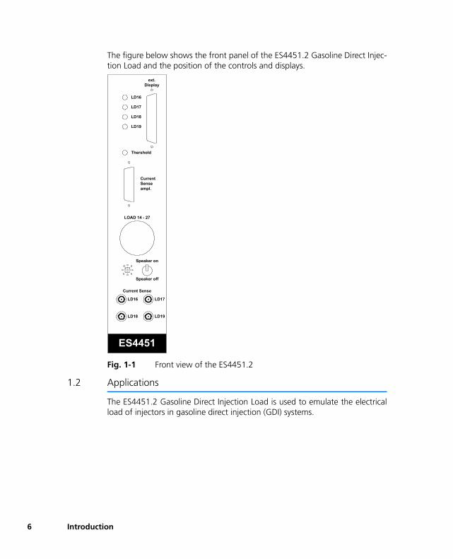
The figure below shows the front panel of the ES4451.2 Gasoline Direct Injec-tion Load and the position of the controls and displays.
Fig. 1-1 Front view of the ES4451.2
1.2 Applications
The ES4451.2 Gasoline Direct Injection Load is used to emulate the electricalload of injectors in gasoline direct injection (GDI) systems.
ES4451
Speaker off
Speaker on
LOAD 14 - 27
LD16
LD17
LD18
LD19
Thershold
CurrentSenseampl.
ext.Display
LD16 LD17
LD18 LD19
Current Sense
Introduction
1.3 Block diagram
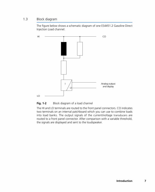
The figure below shows a schematic diagram of one ES4451.2 Gasoline DirectInjection Load channel:
Fig. 1-2 Block diagram of a load channel
The HI and LO terminals are routed to the front panel connectors. CO indicatestwo terminals on an internal patchboard which you can use to combine loadsinto load banks. The output signals of the current/voltage transducers arerouted to a front panel connector. After comparison with a variable threshold,the signals are displayed and sent to the loudspeaker.
I
U
HI
LO
CO
Analog outputand display
Introduction 7

8
Introduction
2 Functional Description
This section contains a detailed description of the features of the load module.
2.1 Equivalent load circuit
The loads are simulated as inductances with parallel and series resistors. Theinductances and resistors are equipped according to your requirements. Thevalues for the standard configuration are listed in Section "Equivalent load cir-cuit" on page 17.
With the standard configuration a BOSCH HDEV5 injector can be emulated.
2.2 Current/voltage transducers
A current/voltage transducer is integrated in each of the four load channels.The conversion ratio is 0.16 V/A. The output signals of the current/voltagetransducers are routed to front panel BNC connectors as analog output signals.
The output signals from the current/voltage transducers amplified by a factor of12 (1.92 V/A) are routed to the 9-pin Sub-D connector that is also on the frontpanel.
2.3 Display
The output signals of the current/voltage transducers are compared with a vari-able threshold. If the threshold is exceeded for a channel, the associated LEDon the front panel comes on.
An acoustic signal sounds every time the threshold is exceeded. You can turnoff the acoustic signal.
2.4 Mechanical design
The ES4451.2 Gasoline Direct Injection Load has a front panel height of 6 U(266.7 mm) and a front panel width of 12 HP (60.72 mm).
The ES4451.2 is mounted in a desk-top enclosure and has an incoming feedfor the power supply via a connector on an additional front panel.
2.5 Connectors
The front panel of the load module has a connector for the load control sig-nals, two Sub-D connectors for the analog output signals, and an external dis-play. In addition the analog output signals of the current/voltage transformersare also routed to four BNC sockets.
Functional Description 9
10
2.5.1 LOAD 14-27 connector
The LOAD 14-27 connector is a 17-pin CANNON socket (female) of type ITTCannon CA20COM and is located on the front panel of the ES4451.2 GasolineDirect Injection Load. This connector provides the control signals of the induc-tive loads for the load module.
2.5.2 Current sense connector
The current sense connector is a 9-pin Sub-D connector and is located on thefront panel of the ES4451.2 Gasoline Direct Injection Load. The voltages pro-portional to the load currents (1.92 V/A) are routed externally via these con-nectors.
Signals at the current sense connector can be routed to a LABCAR via an injec-tor measurement cable.
2.5.3 Display connector
The Display connector is a 15-pin Sub-D connector and is located on the frontpanel of the ES4451.2 Gasoline Direct Injection Load. An external display canbe connected in parallel to the optical display via the Display connector. Thesignals are routed from the comparator outputs via an isolation amplifier foreach load.
2.5.4 BNC sockets
Four BNC sockets on the front panel of the ES4451.2 Gasoline Direct InjectionLoad represent the voltage curve of the connected loads. The output signalfrom each current/voltage transducer (0.16 V/A) is routed to a BNC socket. Thesignal can then be evaluated or reprocessed by devices connected to this con-nector via a coaxial cable.
2.5.5 Power supply
The supply voltages ±15 V and AGND are feed in via a DIN41612 Type F con-nector.
2.6 Patch Board
The HI terminals of each equivalent load circuit are routed to a patch board.There are two terminals on the patch board for each equivalent load circuit.The single loads can be combined to form load banks by using short-circuitjumpers.
The assignment of load channel to terminal on the patch board is listed in Tab.3-5 on page 16.
Functional Description
2.7 Capacitor block
The supply voltages +15 V and -15 V are routed via a capacitor block to stabi-lize the voltage. The capacitor block consists of the electrolytic capacitors C1and C2, and fourteen film capacitors.
Functional Description 11

12
Functional Description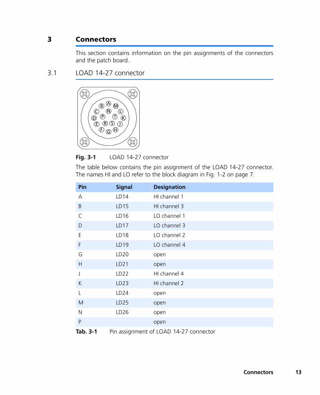
3 Connectors
This section contains information on the pin assignments of the connectorsand the patch board.
3.1 LOAD 14-27 connector
Fig. 3-1 LOAD 14-27 connector
The table below contains the pin assignment of the LOAD 14-27 connector.The names HI and LO refer to the block diagram in Fig. 1-2 on page 7.
Pin Signal Designation
A LD14 HI channel 1
B LD15 HI channel 3
C LD16 LO channel 1
D LD17 LO channel 3
E LD18 LO channel 2
F LD19 LO channel 4
G LD20 open
H LD21 open
J LD22 HI channel 4
K LD23 HI channel 2
L LD24 open
M LD25 open
N LD26 open
P open
Tab. 3-1 Pin assignment of LOAD 14-27 connector
ABC
DE
F G HJ
KL
MN
PR S
T
Connectors 13
14
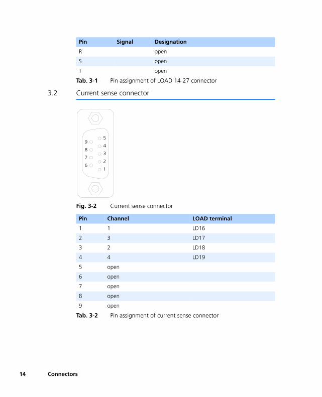
3.2 Current sense connector
Fig. 3-2 Current sense connector
R open
S open
T open
Pin Channel LOAD terminal
1 1 LD16
2 3 LD17
3 2 LD18
4 4 LD19
5 open
6 open
7 open
8 open
9 open
Tab. 3-2 Pin assignment of current sense connector
Pin Signal Designation
Tab. 3-1 Pin assignment of LOAD 14-27 connector
1
2
3
4
59
8
7
6
Connectors
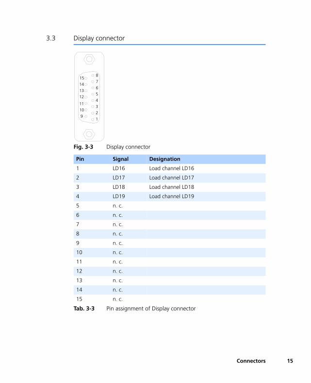
3.3 Display connector
Fig. 3-3 Display connector
Pin Signal Designation
1 LD16 Load channel LD16
2 LD17 Load channel LD17
3 LD18 Load channel LD18
4 LD19 Load channel LD19
5 n. c.
6 n. c.
7 n. c.
8 n. c.
9 n. c.
10 n. c.
11 n. c.
12 n. c.
13 n. c.
14 n. c.
15 n. c.
Tab. 3-3 Pin assignment of Display connector
1
2
3
4
5
15
14
13
12
8
7
6
11
10
9
Connectors 15
16
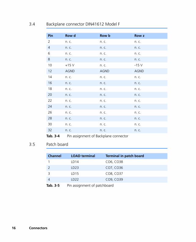
3.4 Backplane connector DIN41612 Model F
3.5 Patch board
Pin Row d Row b Row z
2 n. c. n. c. n. c.
4 n. c. n. c. n. c.
6 n. c. n. c. n. c.
8 n. c. n. c. n. c.
10 +15 V n. c. -15 V
12 AGND AGND AGND
14 n. c. n. c. n. c.
16 n. c. n. c. n. c.
18 n. c. n. c. n. c.
20 n. c. n. c. n. c.
22 n. c. n. c. n. c.
24 n. c. n. c. n. c.
26 n. c. n. c. n. c.
28 n. c. n. c. n. c.
30 n. c. n. c. n. c.
32 n. c. n. c. n. c.
Tab. 3-4 Pin assignment of Backplane connector
Channel LOAD terminal Terminal in patch board
1 LD14 CO6, CO38
2 LD23 CO7, CO36
3 LD15 CO8, CO37
4 LD22 CO9, CO39
Tab. 3-5 Pin assignment of patchboard
Connectors
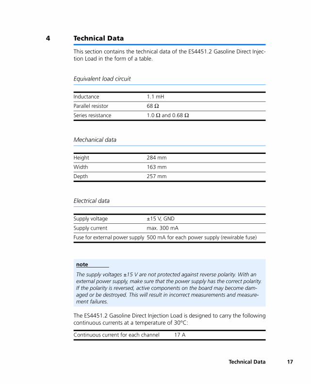
4 Technical Data
This section contains the technical data of the ES4451.2 Gasoline Direct Injec-tion Load in the form of a table.
Equivalent load circuit
Mechanical data
Electrical data
The ES4451.2 Gasoline Direct Injection Load is designed to carry the followingcontinuous currents at a temperature of 30°C:
Inductance 1.1 mH
Parallel resistor 68 ΩSeries resistance 1.0 Ω and 0.68 Ω
Height 284 mm
Width 163 mm
Depth 257 mm
Supply voltage ±15 V, GND
Supply current max. 300 mA
Fuse for external power supply 500 mA for each power supply (rewirable fuse)
note
The supply voltages ±15 V are not protected against reverse polarity. With an external power supply, make sure that the power supply has the correct polarity. If the polarity is reversed, active components on the board may become dam-aged or be destroyed. This will result in incorrect measurements and measure-ment failures.
Continuous current for each channel 17 A
Technical Data 17
18
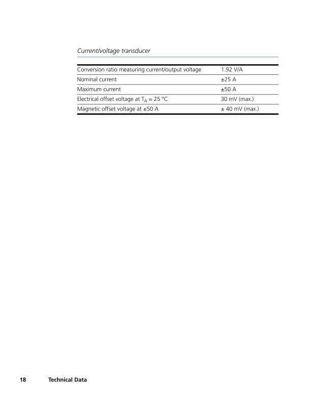
Current/voltage transducer
Conversion ratio measuring current/output voltage 1.92 V/A
Nominal current ±25 A
Maximum current ±50 A
Electrical offset voltage at TA = 25 °C 30 mV (max.)
Magnetic offset voltage at ±50 A ± 40 mV (max.)
Technical Data
5 ETAS Contact Addresses
ETAS HQ
ETAS GmbH
North America
ETAS Inc.
Japan
ETAS K.K.
Great Britain
ETAS Ltd.
Borsigstr. 14 Phone: +49 711 8 96 61-0
70469 Stuttgart Fax: +49 711 8 96 61-105
Germany E-mail: [email protected]
WWW: www.etasgroup.com
3021 Miller Road Phone: +1 888 ETAS INC
Ann Arbor, MI 48103 Fax: +1 734 997-9449
USA E-mail: [email protected]
WWW: www.etasgroup.com
Queen's Tower C-17F Phone: +81 45 222-0900
2-3-5, Minatomirai, Nishi-ku Fax: +81 45 222-0956
Yokohama 220-6217 E-mail: [email protected]
Japan WWW: www.etasgroup.com
Studio 3, Waterside Court Phone: +44 1283 54 65 12
Third Avenue, Centrum 100 Fax: +44 1283 54 87 67
Burton-upon-Trent E-mail: [email protected]
Staffordshire DE14 2WQ WWW: www.etasgroup.com
Great Britain
ETAS Contact Addresses 19
20
France
ETAS S.A.S
Korea
ETAS Korea Co. Ltd.
China
ETAS (Shanghai) Co., Ltd.
1, place des Etats-Unis Phone: +33 (1) 56 70 00 50
SILIC 307 Fax: +33 (1) 56 70 00 51
94588 Rungis Cedex E-mail: [email protected]
France WWW: www.etasgroup.com
4F, 705 Bldg. 70-S Phone: +82 2 57 47 - 016
Yangjae-dong, Seocho-gu Fax: +82 2 57 47 - 120
Seoul 137-889 E-mail: [email protected]
Korea
2404 Bank of China Tower Phone: +86 21 5037 2220
200 Yinchen Road Central Fax: +86 21 5037 2221
Shanghai 200120, P.R. China E-mail: [email protected]
WWW: www.etasgroup.com
ETAS Contact Addresses
Figures
Fig. 1-1 Front view of the ES4451.2 ....................................................................... 6Fig. 1-2 Block diagram of a load channel ............................................................... 7Fig. 3-1 LOAD 14-27 connector ........................................................................... 13Fig. 3-2 Current sense connector ........................................................................ 14Fig. 3-3 Display connector ................................................................................... 15Figures 21

22
Figures
Tables
Tab. 3-1 Pin assignment of LOAD 14-27 connector ............................................... 13Tab. 3-2 Pin assignment of current sense connector.............................................. 14Tab. 3-3 Pin assignment of Display connector ....................................................... 15Tab. 3-4 Pin assignment of Backplane connector................................................... 16Tab. 3-5 Pin assignment of patchboard ................................................................. 16Tables 23

24
Tables
Index
AApplications 6BBackplane connector
Pin assignment 16
CCapacitor block 11Continuous current 17Current sense connector 10
Pin assignment 14Current/voltage transformer
Technical data 18Current/voltage transformers 9
DData
mechanical 17technical 17
Display 9
Display connector 10Pin assignment 15
EElectrolytic capacitor 11Equivalent load circuit 9
FFeatures 5Film capacitor 11Front view 6Fuse for external power supply 17
LLABCAR 10LOAD 14-27 connector 10LOAD 14-27 connectors
Pin assignment 13
OOutput voltage 17
Index 25
26
PPin assignment
Backplane 16Current sense connector 14Display connector 15LOAD 14-27 connector 13
SSupply current 17Supply voltage 17
TTechnical data 17
VVoltage stabilization 11
Index
Related Documents