Engineered Vacuum Systems

Welcome message from author
This document is posted to help you gain knowledge. Please leave a comment to let me know what you think about it! Share it to your friends and learn new things together.
Transcript
Engineered Vacuum Systems
2
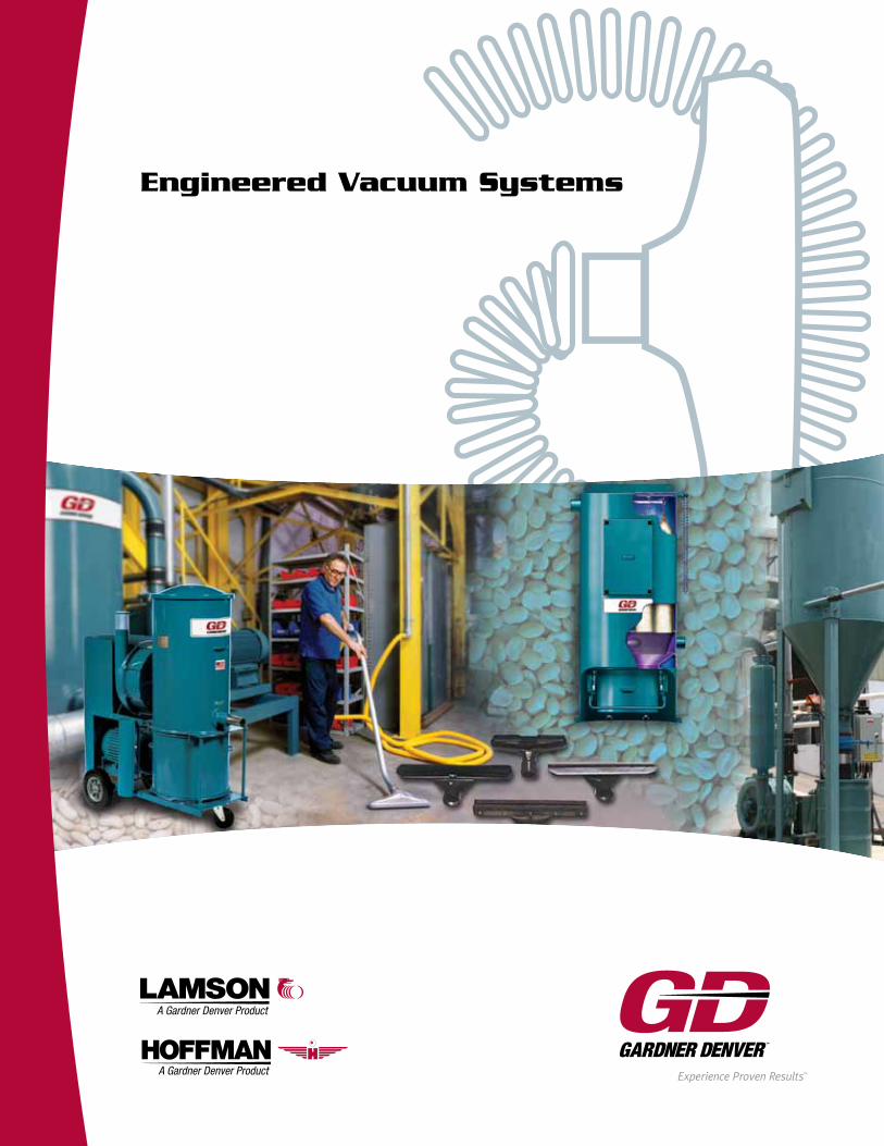
Welcome to the World ofEngineered Vacuum Systems
One Name. Three times The PowerFor more than 100 years, three names have been synonymous with engineered vacuum system solutions for industrial applications: Lamson®, Hoffman® and Invincible®. Today, those legacies are joined, under the Gardner Denver name, creating the most comprehensive line of Engineered Vacuum Systems in the world – the Gardner Denver brand.
Anchored in tradition, this new Gardner Denver Engineered Vacuum System line-up continues a century long commitment to providing customers with innovative design, a comprehensive product line, quality manufacturing and unparalleled responsiveness to customer requirements and service.
Today, as the largest manufacturer of blowers/exhausters in the world, our number one priority continues to be developing long-term relationships with our customers. We are continually striving to reduce lead times and costs, while maintaining the highest performance standards in the industry.
Never in the history of blower/exhauster manufacturers has there been a company as capable of delivering great value, exceptional quality and quick turnaround on orders. So, the next time you’re evaluating options for an engineered vacuum system, call a Gardner Denver professional sales representative to assist you with your application challenges and requirements. Our factory-trained representatives are conveniently located throughout the United States and around the world.
Why Gardner Denver?Three companies, each with over 100 years experience combine, creating a world of possibilities for the ever-expanding needs of the vacuum marketplace. No other company has the capability, reputation and dedicated engineering staff to deliver the most advanced, efficient and dependable high-quality products available today. Gardner Denver’s vacuum expertise includes general housekeeping, pneumatic conveying, product reclamation and hazardous dust control.
Today, it is no longer enough to buy a vacuum system at the best price that will merely do the job. A Gardner Denver Engineered Vacuum System is designed to do more. Our field representatives and application engineers will consider other variables, such as efficiency, convenience, future requirements, healthy work environment and even compliance with domestic and international regulations. An engineered vacuum system will result in optimum performance and capability at the lowest operational expense possible.
Nobody offers a more extensive product line, from the rugged industrial portables and the MultiFlowTM and T-VacTM pre-engineered stationary systems to the custom-designed, engineered vacuum system that services an entire facility using a fabricated or cast multistage centrifugal vacuum producer. Controls are available to protect your vacuum system or to seamlessly integrate the system into a distributed control system. A complete line of Smooth FlowTM tubing and fittings simplify installation and reduce piping loss. Accessories include a complete line of hoses and tools for any requirement, as well as numerous valves, separators and filters to increase the efficiency of your system.
3
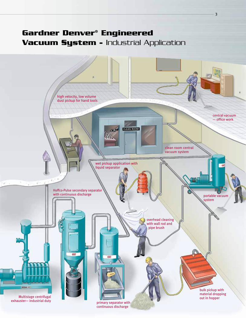
Gardner Denver® Engineered Vacuum System - Industrial Application
high velocity, low volume dust pickup for hand tools
central vacuum — office work
clean room central vacuum system
wet pickup application with liquid separator
Hoffco-Pulse secondary separator with continuous discharge
overhead cleaning with wall rod and pipe brush
portable vacuum system
bulk pickup with material dropping out in hopper
primary separator with continuous discharge
Multistage centrifugal exhauster— industrial duty
4
Lamson and Hoffman Central Vacuum
1 10 100 1,000 10,000 100,0000
2
4
6
8
10
12
14
16
18
20
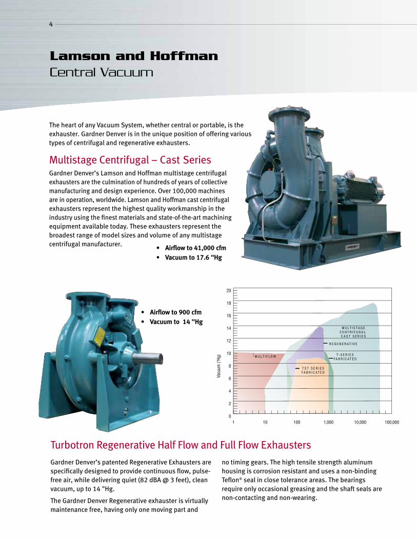
The heart of any Vacuum System, whether central or portable, is the exhauster. Gardner Denver is in the unique position of offering various types of centrifugal and regenerative exhausters.
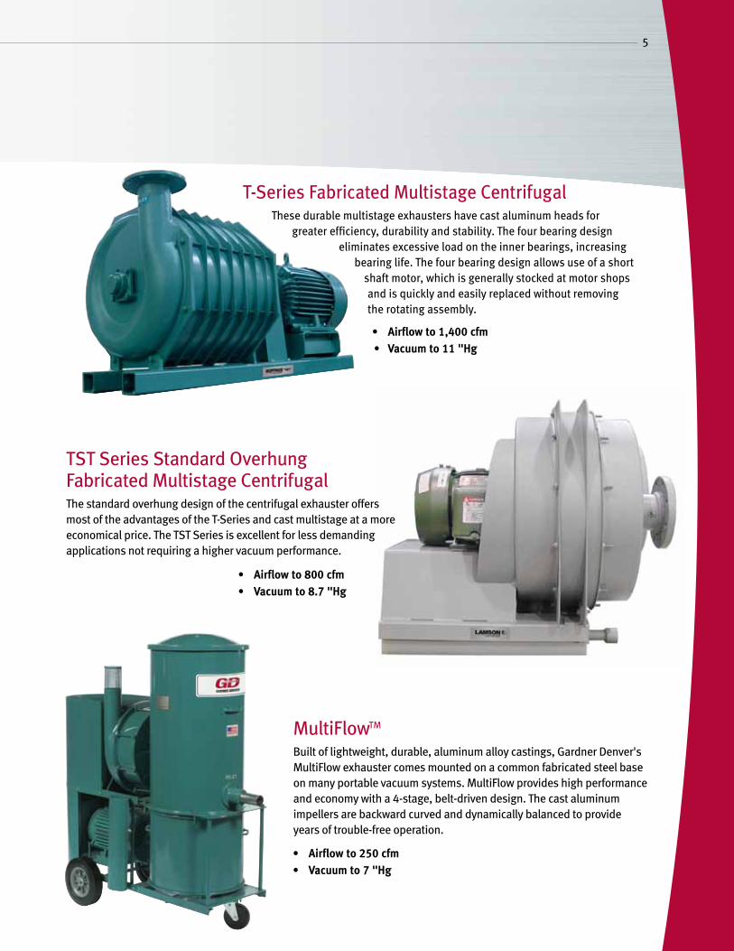
Multistage Centrifugal – Cast SeriesGardner Denver’s Lamson and Hoffman multistage centrifugal exhausters are the culmination of hundreds of years of collective manufacturing and design experience. Over 100,000 machines are in operation, worldwide. Lamson and Hoffman cast centrifugal exhausters represent the highest quality workmanship in the industry using the finest materials and state-of-the-art machining equipment available today. These exhausters represent the broadest range of model sizes and volume of any multistage centrifugal manufacturer. • Airflowto41,000cfm
• Vacuumto17.6"Hg
Turbotron Regenerative Half Flow and Full Flow Exhausters
Gardner Denver’s patented Regenerative Exhausters are specifically designed to provide continuous flow, pulse-free air, while delivering quiet (82 dBA @ 3 feet), clean vacuum, up to 14 "Hg.
The Gardner Denver Regenerative exhauster is virtually maintenance free, having only one moving part and
no timing gears. The high tensile strength aluminum housing is corrosion resistant and uses a non-binding Teflon® seal in close tolerance areas. The bearings require only occasional greasing and the shaft seals are non-contacting and non-wearing.
• Airflowto900cfm• Vacuumto14"Hg
5
T-Series Fabricated Multistage CentrifugalThese durable multistage exhausters have cast aluminum heads for
greater efficiency, durability and stability. The four bearing design eliminates excessive load on the inner bearings, increasing
bearing life. The four bearing design allows use of a short shaft motor, which is generally stocked at motor shops and is quickly and easily replaced without removing the rotating assembly.
TST Series Standard Overhung Fabricated Multistage CentrifugalThe standard overhung design of the centrifugal exhauster offers most of the advantages of the T-Series and cast multistage at a more economical price. The TST Series is excellent for less demanding applications not requiring a higher vacuum performance.
MultiFlowTM
Built of lightweight, durable, aluminum alloy castings, Gardner Denver's MultiFlow exhauster comes mounted on a common fabricated steel base on many portable vacuum systems. MultiFlow provides high performance and economy with a 4-stage, belt-driven design. The cast aluminum impellers are backward curved and dynamically balanced to provide years of trouble-free operation.
• Airflowto800cfm• Vacuumto8.7"Hg
• Airflowto1,400cfm• Vacuumto11"Hg
• Airflowto250cfm• Vacuumto7"Hg
6
EVS Collectors
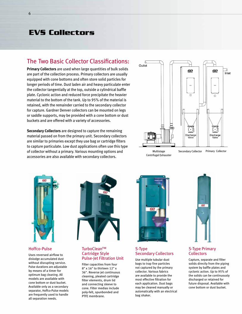
The Two Basic Collector Classifications:PrimaryCollectors are used when large quantities of bulk solids are part of the collection process. Primary collectors are usually equipped with cone bottoms and often store solid particles for longer periods of time. Dust laden air and heavy particulate enter the collector tangentially at the top, outside a cylindrical baffle plate. Cyclonic action and reduced force precipitate the heavier material to the bottom of the tank. Up to 95% of the material is retained, with the remainder carried to the secondary collector for capture. Gardner Denver collectors can be mounted on legs or saddle supports, may be provided with a cone bottom or dust buckets and are offered with a variety of accessories.
Secondary Collectors are designed to capture the remaining material passed on from the primary unit. Secondary collectors are similar to primaries except they use bag or cartridge filters to capture particulate. Low dust applications often use this type of collector without a primary. Various mounting options and accessories are also available with secondary collectors.
Hoffco-PulseUses reversed airflow to dislodge accumulated dust without disrupting service.Pulse durations are adjustable by means of a timer for optimum bag cleaning. All models are available with cone bottom or dust bucket. Available only as a secondary separator, Hoffco-Pulse models are frequently used to handle all separation needs.
TurboClean™ Cartridge Style Pulse-Jet Filtration UnitFilter capacities from four 8" x 16" to thirteen 12" x 36". Reverse jet continuous cleaning, pleated cartridge filter elements, drum lid and connecting sleeve to cone. Filter medias include poly-felt, spunbonded and PTFE membrane.
S-Type Secondary CollectorsUse multiple tubular dust bags to trap fine particles not captured by the primary collector. Various fabrics are available to provide the most effective filtration for each application. Dust bags may be cleaned manually or automatically with an electrical bag shaker.
S-Type Primary CollectorsCapture, separate and filter solids directly from the piping system by baffle plates and cyclonic action. Up to 95% of the solids can be continuously discharged or retained for future disposal. Available with cone bottom or dust bucket.
Secondary Collector Primary CollectorMultistageCentrifugal Exhauster
7
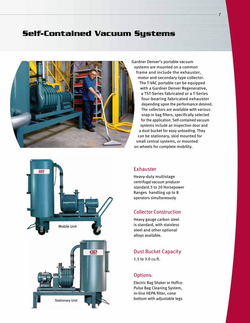
Exhauster Heavy-duty multistage centrifugal vacuum producer standard.5 to 20 Horsepower Ranges handling up to 8 operators simultaneously
Collector Construction
Heavy gauge carbon steel is standard, with stainless steel and other optional alloys available.
Dust Bucket Capacity
1.5 to 3.0 cu.ft.
Options:
Electric Bag Shaker or Hoffco-Pulse Bag Cleaning System, in-line HEPA filter, cone bottom with adjustable legs
Gardner Denver’s portable vacuum systems are mounted on a common
frame and include the exhauster, motor and secondary type collector. The T-VAC portable can be equipped with a Gardner Denver Regenerative, a TST-Series fabricated or a T-Series four-bearing fabricated exhauster depending upon the performance desired. The collectors are available with various snap-in bag filters, specifically selected for the application. Self-contained vacuum systems include an inspection door and
a dust bucket for easy unloading. They can be stationary, skid mounted for
small central systems, or mounted on wheels for complete mobility.
Self-Contained Vacuum Systems
Mobile Unit
Stationary Unit
8
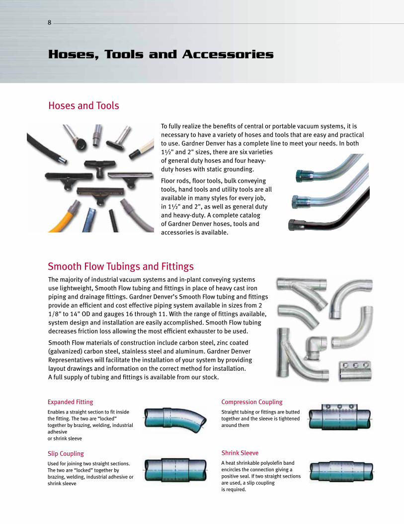
To fully realize the benefits of central or portable vacuum systems, it is necessary to have a variety of hoses and tools that are easy and practical to use. Gardner Denver has a complete line to meet your needs. In both 1½" and 2" sizes, there are six varieties of general duty hoses and four heavy-duty hoses with static grounding.
Floor rods, floor tools, bulk conveying tools, hand tools and utility tools are all available in many styles for every job, in 1½" and 2", as well as general duty and heavy-duty. A complete catalog of Gardner Denver hoses, tools and accessories is available.
Hoses, Tools and Accessories
The majority of industrial vacuum systems and in-plant conveying systems use lightweight, Smooth Flow tubing and fittings in place of heavy cast iron piping and drainage fittings. Gardner Denver’s Smooth Flow tubing and fittings provide an efficient and cost effective piping system available in sizes from 2 1/8" to 14" OD and gauges 16 through 11. With the range of fittings available, system design and installation are easily accomplished. Smooth Flow tubing decreases friction loss allowing the most efficient exhauster to be used.
Smooth Flow materials of construction include carbon steel, zinc coated (galvanized) carbon steel, stainless steel and aluminum. Gardner Denver Representatives will facilitate the installation of your system by providing layout drawings and information on the correct method for installation. A full supply of tubing and fittings is available from our stock.
Smooth Flow Tubings and Fittings
Expanded Fitting
Enables a straight section to fit inside the fitting. The two are “locked” together by brazing, welding, industrial adhesive or shrink sleeve
Slip Coupling
Used for joining two straight sections. The two are “locked” together by brazing, welding, industrial adhesive or shrink sleeve
Compression Coupling
Straight tubing or fittings are butted together and the sleeve is tightened around them
Shrink Sleeve
A heat shrinkable polyolefin band encircles the connection giving a positive seal. If two straight sections are used, a slip coupling is required.
Hoses and Tools
9
Air-Lock Valves 8" single or double flanged for controlling material discharge from collectors. Whether manual or air operated, these valves are leakproof and self-compensate for wear. Rotary and slide valves are also available.
Automatic Air Bleed System Allows operation of vacuum cleaning system during low demand periods.
Equalization Line Allows plastic liners to be securely positioned in collector dust buckets.
In-Line Filters All vacuum systems can be fitted with HEPA absolute filters (99.97% effective on 0.3 micron size materials.)
Collector Options Wet separators are available to remove moisture from the air stream. Drum Top Separators are excellent for removing materials, prior to the tubing system, utilizing a standard 30 or 55 gallon drum.
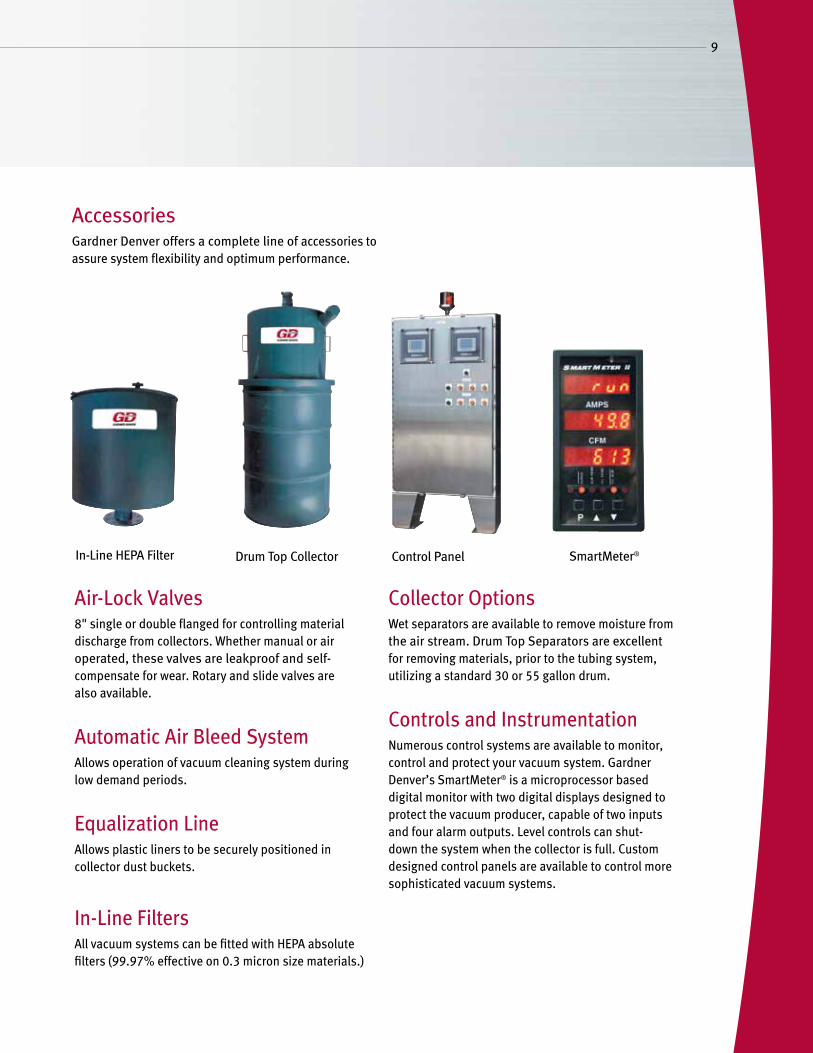
Controls and Instrumentation Numerous control systems are available to monitor, control and protect your vacuum system. Gardner Denver’s SmartMeter® is a microprocessor based digital monitor with two digital displays designed to protect the vacuum producer, capable of two inputs and four alarm outputs. Level controls can shut-down the system when the collector is full. Custom designed control panels are available to control more sophisticated vacuum systems.
AccessoriesGardner Denver offers a complete line of accessories to assure system flexibility and optimum performance.
In-Line HEPA Filter Drum Top Collector Control Panel SmartMeter®
10
Engineered Vacuum System Design Guide
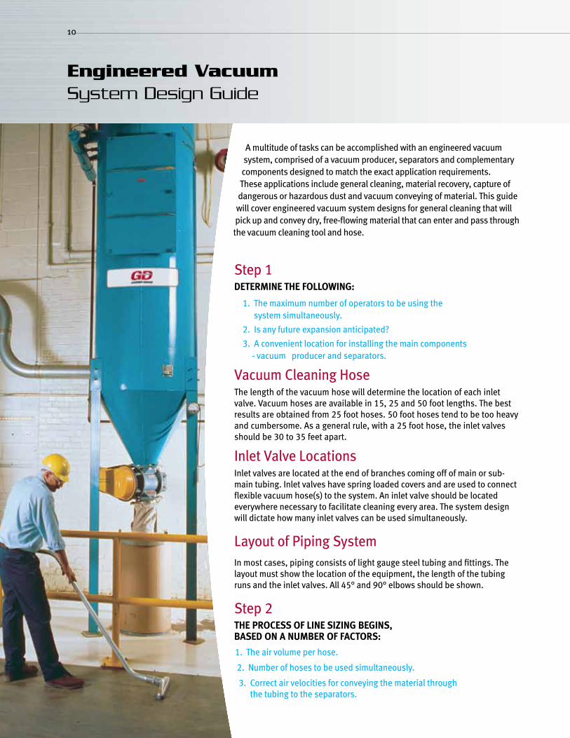
A multitude of tasks can be accomplished with an engineered vacuum system, comprised of a vacuum producer, separators and complementary components designed to match the exact application requirements. These applications include general cleaning, material recovery, capture of dangerous or hazardous dust and vacuum conveying of material. This guide will cover engineered vacuum system designs for general cleaning that will pick up and convey dry, free-flowing material that can enter and pass through the vacuum cleaning tool and hose.
Step 1DeterminetHefollowing:
1. The maximum number of operators to be using the system simultaneously.
2. Is any future expansion anticipated?
3. A convenient location for installing the main components - vacuum producer and separators.
Vacuum Cleaning HoseThe length of the vacuum hose will determine the location of each inlet valve. Vacuum hoses are available in 15, 25 and 50 foot lengths. The best results are obtained from 25 foot hoses. 50 foot hoses tend to be too heavy and cumbersome. As a general rule, with a 25 foot hose, the inlet valves should be 30 to 35 feet apart.
Inlet Valve LocationsInlet valves are located at the end of branches coming off of main or sub-main tubing. Inlet valves have spring loaded covers and are used to connect flexible vacuum hose(s) to the system. An inlet valve should be located everywhere necessary to facilitate cleaning every area. The system design will dictate how many inlet valves can be used simultaneously.
Layout of Piping SystemIn most cases, piping consists of light gauge steel tubing and fittings. The layout must show the location of the equipment, the length of the tubing runs and the inlet valves. All 45° and 90° elbows should be shown.
Step 2tHeProCessoflinesizingbegins,bAseDonAnumberoffACtors:
1. The air volume per hose.
2. Number of hoses to be used simultaneously.
3. Correct air velocities for conveying the material through the tubing to the separators.
Air Volume Per HoSe
The hose diameter, particle size and amount of material to be conveyed determines the air volume. Most systems work well with a minimum of 80 SCFM in a 1.5" diameter hose. Heavier material may require increased airflow, ranging to 120 SCFM or more, for some material. 2" diameter hoses typically require 150 to 200 SCFM, depending upon conditions.
Step 3systemlosses
To choose the proper vacuum producer, system losses or resistance must be determined. Total loss consists of:
1. Loss through hoses and tools 2. Loss through lines (straight runs and bends) 3. Loss through separators
CAlCulAtinglosses
1. Chart 3 indicates the loss for a given hose length with tool.
2. Friction loss in the lines or tubing, can be determined from Chart 5.
3. The friction loss through a 90° elbow is equivalent to 12 feet of straight tubing and a 45° elbow is similar to 7 feet of tubing.
See Charts on pages 13, 14 and 15.
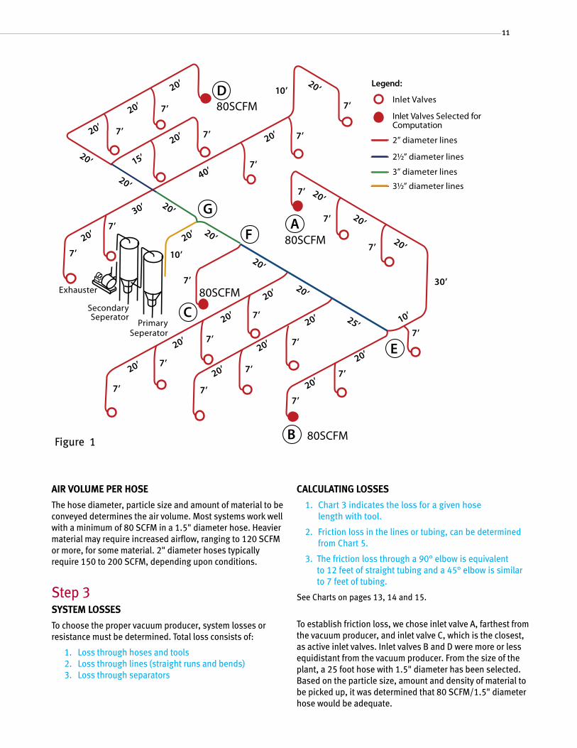
To establish friction loss, we chose inlet valve A, farthest from the vacuum producer, and inlet valve C, which is the closest, as active inlet valves. Inlet valves B and D were more or less equidistant from the vacuum producer. From the size of the plant, a 25 foot hose with 1.5" diameter has been selected. Based on the particle size, amount and density of material to be picked up, it was determined that 80 SCFM/1.5" diameter hose would be adequate.
11
Inlet Valves
Legend:
Inlet Valves Selected forComputation
2” diameter lines
2½” diameter lines
3½” diameter lines
3” diameter lines
7’
7’
7’
7’
7’
7’
7’
7’
7’
7’
30’
7’
7’
7’
7’
7’
7’
7’
7’
10’
7’
7’
7’
7’
10’20’
20’
20’
20’
20’
25’
20’
20’
20’
20’
20’
20’
20’
20’
15’
20’
40’
30’
20’
20’
20’
20’
20’20’
20’
20’
20’
20’
10’
20’
20’
D80SCFM
G
FA
80SCFM
C80SCFM
E
80SCFMB
PrimarySeperator
SecondarySeperator
Exhauster
Figure 1
12
Engineered Vacuum System Design Guide
losses
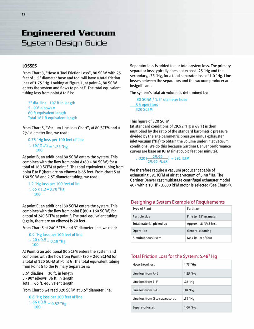
From Chart 3, “Hose & Tool Friction Loss”, 80 SCFM with 25 feet of 1.5" diameter hose and tool will have a total friction loss of 1.75 "Hg. Looking at Figure 1, at point A, 80 SCFM enters the system and flows to point E. The total equivalent tubing loss from point A to E is: 2" dia. line 107 ft in length 5 - 90° elbows = 60 ft equivalent length Total 167 ft equivalent length
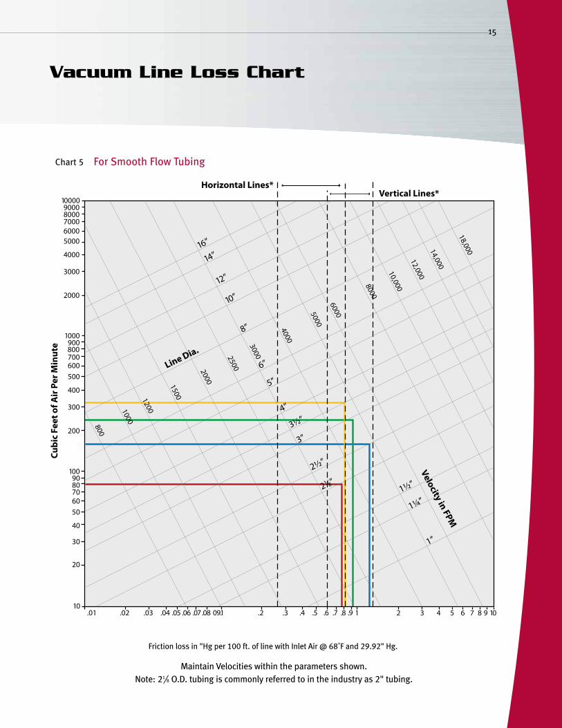
From Chart 5, “Vacuum Line Loss Chart”, at 80 SCFM and a 21⁄8" diameter line, we read:
0.75 "Hg loss per 100 feet of line ∴ 167 x .75 = 1.25 "Hg 100
At point B, an additional 80 SCFM enters the system. This combines with the flow from point A (80 + 80 SCFM) for a total of 160 SCFM at point E. The total equivalent tubing from point E to F (there are no elbows) is 65 feet. From chart 5 at 160 SCFM and 2.5” diameter tubing, we read:
1.2 "Hg loss per 100 feet of lin ∴ 65 x 1.2 = 0.78 "Hg 100
At point C, an additional 80 SCFM enters the system. This combines with the flow from point E (80 + 160 SCFM) for a total of 240 SCFM at point F. The total equivalent tubing (again, there are no elbows) is 20 feet.
From Chart 5 at 240 SCFM and 3" diameter line, we read:
0.9 "Hg loss per 100 feet of line ∴ 20 x 0.9 = 0.18 "Hg 100
At Point G an additional 80 SCFM enters the system and combines with the flow from Point F (80 + 240 SCFM) for a total of 320 SCFM at Point G. The total equivalent tubing from Point G to the Primary Separator is:
3.5" dia.line 30 ft. in length3 - 90° elbows 36 ft. in lengthTotal 66 ft. equivalent length
From Chart 5 we read 320 SCFM at 3.5" diameter line:
0.8 "Hg loss per 100 feet of line ∴ 66 x 0.8 = 0.52 "Hg 100
Separator loss is added to our total system loss. The primary separator loss typically does not exceed .25 "Hg and the secondary, .75 "Hg, for a total separator loss of 1.0 "Hg. Line losses between the separators and the vacuum producer are insignificant.
The system’s total air volume is determined by:
80 SCFM / 1.5" diameter hose X 4 operators 320 SCFM
This figure of 320 SCFM (at standard conditions of 29.92 "Hg & 68°F) is then multiplied by the ratio of the standard barometric pressure divided by the site barometric pressure minus exhauster inlet vacuum ("Hg) to obtain the volume under inlet vacuum conditions. We do this because Gardner Denver performance curves are base on ICFM (inlet cubic feet per minute).
∴320 ( ) = 391 ICFM
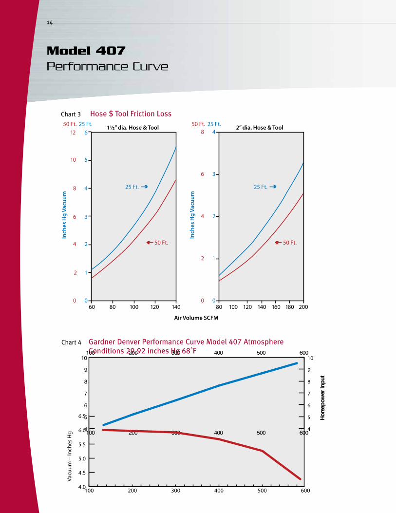
We therefore require a vacuum producer capable of exhausting 391 ICFM of air at a vacuum of 5.48 "Hg. The Gardner Denver cast multistage centrifugal exhauster model 407 with a 10 HP - 3,600 RPM motor is selected (See Chart 4).
Total Friction Loss for the System: 5.48" Hg
Hose & tool loss 1.75 "Hg
Line loss from A–E 1.25 "Hg
Line loss from E–F .78 "Hg
Line loss from F–G .18 "Hg
Line loss from G to separatoros .52 "Hg
Separatorlosses 1.00 "Hg
Designing a System Example of RequirementsType of Plant Fertilizer
Particle size Fine to .25" granular
Total material picked up Approx. 18 ft³/8 hrs.
Operation General cleaning
Simultaneous users Max imum of four
29.9229.92 -5.48

rAtioofAirflow/filterAreA
The particle size and the volume of the material being picked up and the frequency of the bag cleaning (shaking them to dislodge the dust) will determine the ratio of air flow (ICFM) to ft2 of filter area. Hose&tools
Always start with a standard set of tools and add any extras required by your specific application, referring to the Gardner Denver Hoses, Tools & Accessories brochure. instAllAtionsAteleVAtion
Corrections in vacuum producer performance are necessary at elevations above sea level.
If we take our previous example at 4,000 feet, the air volume was 320 SCFM/ 391 ICFM. On chart 2, we see the new barometric pressure at 4,000.
Air Volume correction: ∴320 SCFM ( ) = 470 ICFM "Hg vacuum correction: 5.48 "Hg( ) = 6.3 "Hg
A new vacuum producer capable of exhausting 470 ICFM at 6.3 "Hg vacuum to meet the same requirements at 4,000 foot elevation is required. The horsepower is found to be 10.5 at standard conditions, however, a correction is necessary at 4,000 ft:
10.5 HP ( ) = 9.1 BHP Therefore, a 10 HP, 3,600 RPM motor is required. Note: new performance curve is not shown. ConClusion
This brief Design Guide does not cover all of the many design variables which might be encountered. It is meant to be used as a tool to give the purchaser an idea of the basic factors involved in system design.
Chart 2
Average absolute atmospheric pressure
Altitude in feetabove sea level
Inches ofmercury ("Hg)
Lbs. per Sq. In.(absolute psig)
sea level 0 29.92 14.7
+500 29.39 14.4
+1,000 28.87 14.2
+1,500 28.33 13.9
+2,000 27.82 13.7
+3,000 26.81 13.2
+4,000 25.85 12.7
+5,000 24.90 12.2
+6,000 23.98 11.7
+7,000 23.10 11.3
+8,000 22.22 10.8
+9,000 21.39 10.5
+10,000 20.58 10.1
13
29.9225.85-5.48
29.9225.85
Chart 1Maximum recommended ICFM passing through each square foot of filter area
Material Manual cleaning
Continuous cleaning
Carbon black, talc or other fine fugitive material 1 1–2
Usual dust and debris encountered in shops and industrial work or storage areas 3 6–8
Commercial installation & hospitals (light dust conditions)
5 8–10
Little or no dust, such as clean rooms up to 8 12
This chart provides approximate guidelines for adequate air/filter ratio.
25.8529.92
14
Model 407 Performance Curve
Chart 3
Chart 4 Gardner Denver Performance Curve Model 407 Atmosphere Conditions 29.92 inches Hg 68˚F
600 00 0
12
24
36
48
12
24
36
4 25 Ft.
50 Ft.
8
510
6121½” dia. Hose & Tool 2” dia. Hose & Tool
Hose & Tool Friction Loss
Air Volume SCFM
Inch
es H
g Va
cuum
Inch
es H
g Va
cuum
50 Ft. 25 Ft. 50 Ft. 25 Ft.
80 80100 100120 120140 140 160 180 200
25 Ft.
50 Ft.
Hose $ Tool Friction Loss
100 200 300 400 500 600
100 200 300 400 500 600
4
5
6
7
8
9
10
4
5
6
7
8
9
10
100 200 300 400 500 6004.0
4.5
5.0
5.5
6.0
6.5
Volume – Inlet CFM
Vacu
um –
Inch
es H
g
Hor
sepo
wer
Inpu
t
1000090008000700060005000
4000
3000
2000
1000900800700600500
400
300
200
800
1000
1200
1500
2000
2500
3000
4000
5000
6000
8000
10,000
12,00014,000
18,000
1009080706050
40
30
20
10.01 .02 .03 .04 .05 .06 .07.08 09.1 .2 .3 .4 .5 .6 .7 .8 .9 1 2 3 4 5 6 7 8 9 10
Cubi
c Fe
et o
f Air
Per
Min
ute
Line Dia.
16”
14”
12”
10”
8”
6”
5”
4”
3½”
2½”
3”
2 ”1/8
1”
1¼”1½”
Velocity in FPM
Horizontal Lines*Vertical Lines*
15
For Smooth Flow Tubing
Maintain Velocities within the parameters shown.Note: 21⁄8 O.D. tubing is commonly referred to in the industry as 2" tubing.
Friction loss in "Hg per 100 ft. of line with Inlet Air @ 68˚F and 29.92" Hg.
Chart 5
Vacuum Line Loss Chart
Please recycle after use.
www.GardnerDenverProducts.com [email protected]
Gardner Denver, Inc. 100 Gardner Park, Peachtree City, GA 30269 New Equipment Sales: (800) 543-7736 Phone: (770) 632-5000 Fax: (700) 486-5628
Aftermarket Parts Sales: (800) 982-3009 Phone: (770) 632-5000 Fax: (700) 486-5530
Specifications subject to change without notice ©2009 Gardner Denver, Inc. Litho in U.S.A.GDCF-1-200- 2nd Ed. 3/10
Member 8
ACCREDITED
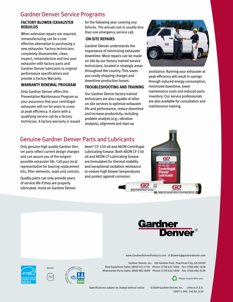
Gardner Denver Service ProgramsfACtoryblower/exHAusterrebuilDs
When extensive repairs are required, remanufacturing can be a cost effective alternative to purchasing a new exhauster. Factory technicians completely disassemble, clean, inspect, remanufacture and test your exhauster with factory parts and Gardner Denver lubricants to original performance specifications and provide a Factory Warranty.
wArrAntyrenewAlProgrAm
Only Gardner Denver offers this Preventative Maintenance Program as your assurance that your centrifugal exhauster will run for years to come at peak efficiency. It starts with a qualifying service call by a factory technician. A factory warranty is issued
for the following year covering any failures. The annual cost is usually less than one emergency service call.
on-siterePAirs
Gardner Denver understands the importance of minimizing exhauster downtime. Most repairs can be made on site by our factory trained service technicians, located in strategic areas throughout the country. This saves you costly shipping charges and downtime production losses.
troublesHootingAnDtrAining
Our Gardner Denver factory trained technicians are also capable of other on-site services to optimize exhauster life and performance, reduce downtime and increase productivity, including problem analysis (e.g., vibration analysis), alignment and start-up
assistance. Running your exhauster at peak efficiency will result in savings through reduced energy consumption, minimized downtime, lower maintenance costs and reduced parts inventory. Our service professionals are also available for consultation and maintenance training.
Genuine Gardner Denver Parts and LubricantsOnly genuine high quality Gardner Den-ver parts reflect current design changes and can assure you of the longest possible exhauster life. Call your local representative for bearing replacement kits, filter elements, seals and controls.
Quality parts can only provide years of service life if they are properly lubricated. Insist on Gardner Denver
Aeon® CF-150 oil and AEON Centrifugal Lubricating Grease. Both AEON CF-150 oil and AEON CF Lubricating Grease are formulated for thermal stability and exceptional oxidation resistance to endure high blower temperatures and protect against corrosion.
Related Documents