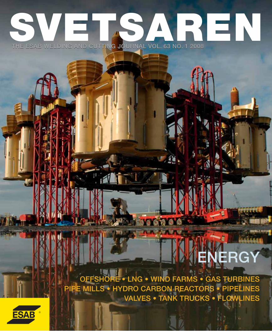
THE ESAB WELDING AND CUTTING JOURNAL VOL. 63 NO. 1 2008 THE ESAB WELDING AND CUTTING JOURNAL VOL. 63 NO. 1 2008 ENERGY OFFSHORE • LNG • WIND FARMS • GAS TURBINES PIPE MILLS • HYDRO CARBON REACTORS • PIPELINES VALVES • TANK TRUCKS • FLOWLINES

Welcome message from author
This document is posted to help you gain knowledge. Please leave a comment to let me know what you think about it! Share it to your friends and learn new things together.
Transcript
THE ESAB WELDING AND CUTTING JOURNAL VOL. 63 NO. 1 2008THE ESAB WELDING AND CUTTING JOURNAL VOL. 63 NO. 1 2008
ENERGYOFFSHORE • LNG • WIND FARMS • GAS TURBINES
PIPE MILLS • HYDRO CARBON REACTORS • PIPELINES VALVES • TANK TRUCKS • FLOWLINES
It does not matter if our customers operate in China, Germany, US, Brazil or Sweden. Wherever in the world you buy ESAB products, these are produced in accordance with the same global EHS standards where occupational and product health & safety always comes first. Let us show you what a well managed company can do for you!
We have now gained
OHSAS 18001 group
certification from DNV.
Our group Environ-
mental, Health & Safety
Management System
was already ISO14001
certified. This is believed
to be the most compre-
hensive certification
achieved by any global
company to date.
It includes all production
operations, sales and
central functions within
ESAB at 1 July 2007.
Our system will benefit our customers
Box Information.com
Setting new standards
www.esab.com
Svetsaren
HARALD HESPE
THE ESAB WELDING AND CUTTING JOURNAL VOL. 63 NO. 1 2008THE ESAB WELDING AND CUTTING JOURNAL VOL. 63 NO. 1 2008
ENERGYOFFSHORE • LNG • WIND FARMS • GAS TURBINES
PIPE MILLS • HYDRO CARBON REACTORS • PIPELINES VALVES • TANK TRUCKS • FLOWLINES
Dear reader,
Energy makes the world tick. Its generation and supply is a significant factor in global development, having an intimate effect on life style and quality. The lack of energy availability in many parts of the world, the growing awareness of the necessity to manage the limited resources and excessive and sometimes wasteful human behaviour, all create a challenge for the future.
The limited availability of fossil fuels and their harmful effect on our environment, forces us to develop renewable forms of energy and, also, to explore the still enormous potential savings we can make in energy consumption. The latter is an integral element of ESAB’s environmental management system- rewarded with the ISO 14001 global environmental certification.
Our energy efficiency ratio in production sites and offices (revenues/energy use), for example, has doubled in 10 years (1996-2006) – as a result of focused and planned activities - and we intend to double this again in the coming decade. Another of our long- term strategic objectives is to significantly increase the use of energy from renewable sources (now 5%). This corporate policy guides our development efforts and demonstrates that leading industrial enterprises can take the initiative and can change traditional behaviour.
The exploration of fossil fuel based resources has accelerated and taken on a new pathin commercialising previously non-economic areas. Exploration takes place in moreremote areas, more challenging environments in terms of climate and we are exposed todeep sea drilling and many more difficult engineering challenges. Wind power has become a global priority and we see renewed worldwide investment in nuclear power generation.
This issue of Svetsaren features articles and application stories that illustrate the success of our clients and the deep involvement of ESAB as a welding and cutting solution provider for the energy generating industry.
Good reading,
HARALD HESPE
MANAGING DIRECTOR ESAB MIDDLE EAST FZE
ENERGY
Articles in Svetsaren may be reproduced without permission, but with an acknowledgement to ESAB.
PublisherJohan Elvander
EditorBen Altemühl
Editorial committeeTony Anderson, Klaus Blome, Carl Bandhauer, Christophe Gregoir, Joakim Cahlin, Dan Erlandsson, Björn Torstensson, Nils Thalberg, Annika Tedeholm,José Roberto Domingues, Antonio Couto Plais.
AddressSvetsarenESAB AB Central Market CommunicationsBox 8004 S-402 77 GothenburgSweden
Internet addresshttp://www.esab.comE-mail: [email protected]
Printed in The Netherlands by True Colours
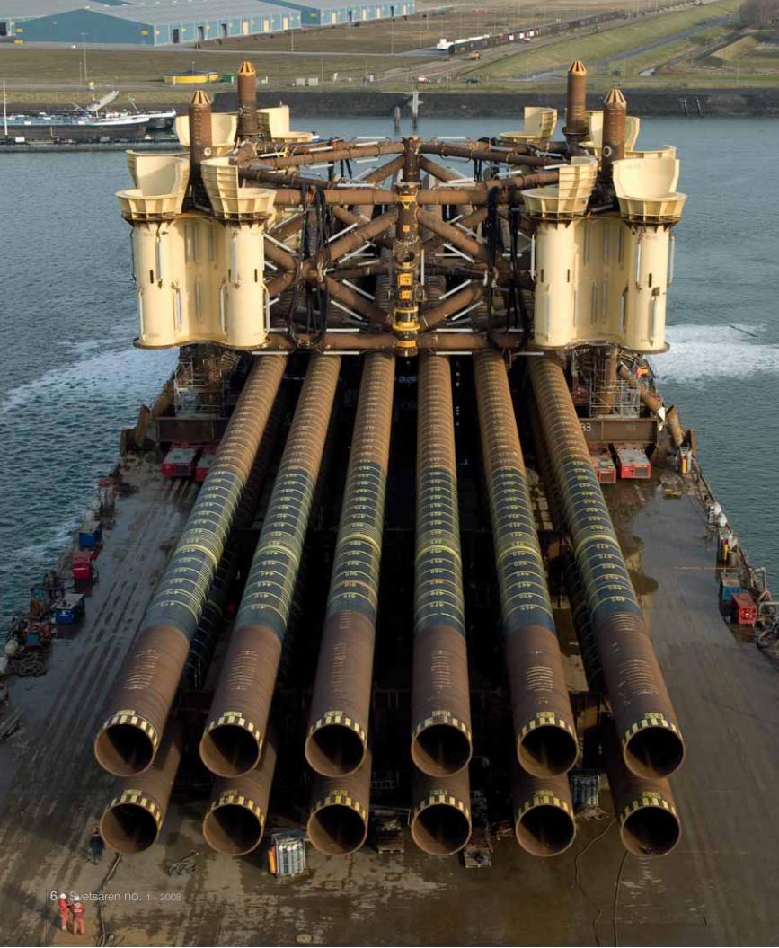
Lifting of the Tombua Landana platform template at Heerema, Vlissingen, The Netherlands.
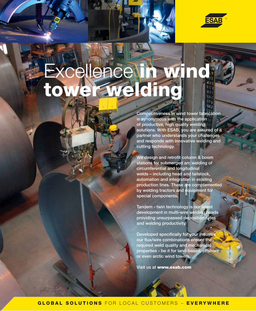
Competitiveness in wind tower fabrication is synonymous with the application of productive, high quality welding solutions. With ESAB, you are assured of a partner who understands your challenges and responds with innovative welding and cutting technology.
We design and retrofi t column & boom stations for submerged arc welding of circumferential and longitudinal welds – including head and tailstock, automation and integration in existing production lines. These are complemented by welding tractors and equipment for special components.
Tandem - twin technology is our latest development in multi-wire welding heads providing unsurpassed deposition rates and welding productivity.
Developed specifi cally for your industry, our fl ux/wire combinations ensure the required weld quality and mechanical properties - be it for land-based, offshore or even arctic wind towers.
Visit us at www.esab.com
Excellence in wind tower welding

ContentsTemplate for monster platform challengesHeerema.ESAB low-hydrogen consumable techno-logy crucial in safe and productive welding.
Port of Marseille sees LNG storage tanks erected with ESAB welding technology.Project, awarded to a joint venture of Saipem and Sofregaz, sub-contracted to the Italian Bentini Group SpA.
07
32 Paresa SpA construct spheres for the Kuwait petrochemical industry Part of integrated petrochemical plant for hydrocarbons processing.
15
18 SIF Group bv at the foundation of Dutch wind energyESAB SAW technology crucial in the production of piles and transition pieces for the Q7 North Sea wind farm.
23 Zorya-Mashproekt relies on ESAB for arc welding of gas turbine componentsZorya-Mashproekt is a leading Ukranian producer of industrial and marine gas turbine power plants and engines.
26 Complete and reliable partner for pipe mills.The latest ESAB equipment and consum-ables for longitudinal welding.
ESW Inconel strip claddingSolution to clad steel shortage for Maritime Industrial Services, Dubai.
34
Cladding of valves for petrochemical plants.Valve manufacture and repair is a growth industry.
41
Techint and ESAB Brazil - partners in the construction of the PRA-1 jacket. Technical partnership fundamental to the success of the project.
43
Manufacture of mobile gasoline tanks in AlMg5 alloy at ZAO BECEMA, Russia.ESAB assists in conversion from steel to aluminium.
47
Belleli Energy SpA reactors at the heart of Qatar’s Pearl Gas-to-Liquids Plant.ESAB arc welding consumables deliver quality and productivity.
51
High integrity flowline welding at LMIESAB orbital TIG technology crucial.
56 Product News • New power sources for orbital welding• Robust and powerful MIG/MAG Power
sources for heavy duty welding• Caddy™ - the portable solution for
professional welding• New Origo welding machine for
demanding applications• Reactive welding helmets• AUTOREX – The first, totally encapsu-
lated, automatic plasma cutting centre• TramtracTM II – flexible solution for the
repair of embedded city tramway rails.• New submerged arc fluxes• OK Tubrod 14.11 – Metal cored wire
for high speed thin plate welding• VacPac gets slimmer
58
Mechanised pipeline welding in the Saudi desertMagnatech orbital welding system and ESAB cored wire do the job.
37
6 - Svetsaren no. 1 - 2008
Svetsaren no. 1 - 2008 - 7
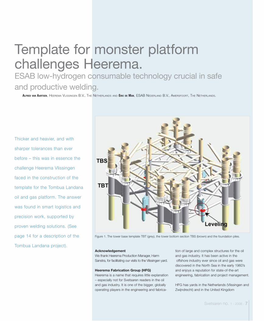
Figure 1. The tower base template TBT (grey), the tower bottom section TBS (brown) and the foundation piles.
Thicker and heavier, and with
sharper tolerances than ever
before – this was in essence the
challenge Heerema Vlissingen
faced in the construction of the
template for the Tombua Landana
oil and gas platform. The answer
was found in smart logistics and
precision work, supported by
proven welding solutions. (See
page 14 for a description of the
Tombua Landana project).AcknowledgementWe thank Heerema Production Manager, Harm Sanstra, for facilitating our visits to the Vlissingen yard. Heerema Fabrication Group (HFG)Heerema is a name that requires little explanation – especially not for Svetsaren readers in the oil and gas industry. It is one of the bigger, globally operating players in the engineering and fabrica-
tion of large and complex structures for the oil and gas industry. It has been active in the offshore industry ever since oil and gas were discovered in the North Sea in the early 1960’s and enjoys a reputation for state-of-the-art engineering, fabrication and project management. HFG has yards in the Netherlands (Vlissingen and Zwijndrecht) and in the United Kingdom
ALFRED VAN AARTSEN, HEEREMA VLISSINGEN B.V., THE NETHERLANDS AND ERIC DE MAN, ESAB NEDERLAND B.V., AMERSFOORT, THE NETHERLANDS.
Template for monster platform challenges Heerema.ESAB low-hydrogen consumable technology crucial in safe and productive welding.
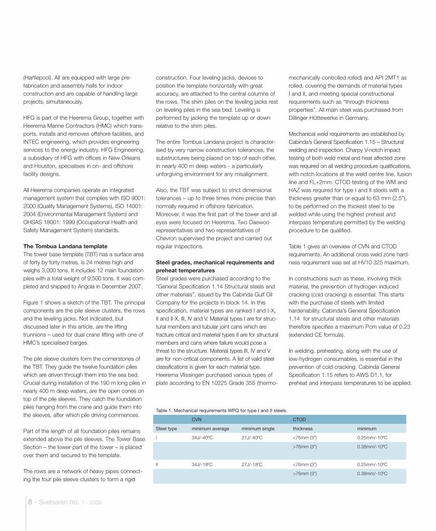
Table 1. Mechanical requirements WPQ for type I and II steels.
CVN CTOD
Steel type minimum average minimum single thickness minimum
I 34J/-40ºC 27J/-40ºC <76mm (3”) 0.25mm/-10ºC
>76mm (3”) 0.38mm/-10ºC
II 34J/-18ºC 27J/-18ºC <76mm (3”) 0.25mm/-10ºC
>76mm (3”) 0.38mm/-10ºC
8 - Svetsaren no. 1 - 2008
(Hartlepool). All are equipped with large pre-fabrication and assembly halls for indoor construction and are capable of handling large projects, simultaneously.
HFG is part of the Heerema Group, together with Heerema Marine Contractors (HMC) which trans-ports, installs and removes offshore facilities, and INTEC engineering, which provides engineering services to the energy industry. HFG Engineering, a subsidiary of HFG with offices in New Orleans and Houston, specialises in on- and offshore facility designs.
All Heerema companies operate an integrated management system that complies with ISO 9001: 2000 (Quality Management Systems), ISO 14001: 2004 (Environmental Management System) and OHSAS 18001: 1999 (Occupational Health and Safety Management System) standards.
The Tombua Landana templateThe tower base template (TBT) has a surface area of forty by forty metres, is 24 metres high and weighs 3,000 tons. It includes 12 main foundation piles with a total weight of 9,500 tons. It was com-pleted and shipped to Angola in December 2007.
Figure 1 shows a sketch of the TBT. The principal components are the pile sleeve clusters, the rows and the leveling jacks. Not indicated, but discussed later in this article, are the lifting trunnions – used for dual crane lifting with one of HMC’s specialised barges.
The pile sleeve clusters form the cornerstones of the TBT. They guide the twelve foundation piles which are driven through them into the sea bed. Crucial during installation of the 190 m long piles in nearly 400 m deep waters, are the open cones on top of the pile sleeves. They catch the foundation piles hanging from the crane and guide them into the sleeves, after which pile driving commences.
Part of the length of all foundation piles remains extended above the pile sleeves. The Tower Base Section – the lower part of the tower – is placed over them and secured to the template.
The rows are a network of heavy pipes connect-ing the four pile sleeve clusters to form a rigid
construction. Four leveling jacks, devices to position the template horizontally with great accuracy, are attached to the central columns of the rows. The shim piles on the leveling jacks rest on leveling piles in the sea bed. Leveling is performed by jacking the template up or down relative to the shim piles.
The entire Tombua Landana project is character-ised by very narrow construction tolerances, the substructures being placed on top of each other, in nearly 400 m deep waters - a particularly unforgiving environment for any misalignment.
Also, the TBT was subject to strict dimensional tolerances – up to three times more precise than normally required in offshore fabrication. Moreover, it was the first part of the tower and all eyes were focused on Heerema. Two Daewoo representatives and two representatives of Chevron supervised the project and carried out regular inspections.
Steel grades, mechanical requirements and preheat temperaturesSteel grades were purchased according to the “General Specification 1.14 Structural steels and other materials”, issued by the Cabinda Gulf Oil Company for the projects in block 14. In this specification, material types are ranked I and I-X, II and II-X, III, IV and V. Material types I are for struc-tural members and tubular joint cans which are fracture critical and material types II are for structural members and cans where failure would pose a threat to the structure. Material types III, IV and V are for non-critical components. A list of valid steel classifications is given for each material type. Heerema Vlissingen purchased various types of plate according to EN 10225 Grade 355 (thermo-
mechanically controlled rolled) and API 2MT1 as rolled, covering the demands of material typesI and II, and meeting special constructional requirements such as “through thickness properties”. All main steel was purchased from Dillinger Hüttewerke in Germany.
Mechanical weld requirements are established by Cabinda’s General Specification 1.15 – Structural welding and inspection. Charpy V-notch impact testing of both weld metal and heat affected zone was required on all welding procedure qualifications, with notch locations at the weld centre line, fusion line and FL+2mm. CTOD testing of the WM and HAZ was required for type I and II steels with a thickness greater than or equal to 63 mm (2.5”), to be performed on the thickest steel to be welded while using the highest preheat and interpass temperature permitted by the welding procedure to be qualified.
Table 1 gives an overview of CVN and CTOD requirements. An additional cross weld zone hard-ness requirement was set at HV10 325 maximum.
In constructions such as these, involving thick material, the prevention of hydrogen induced cracking (cold cracking) is essential. This starts with the purchase of steels with limited hardenability. Cabinda’s General Specification 1.14 for structural steels and other materials therefore specifies a maximum Pcm value of 0.23 (extended CE formula).
In welding, preheating, along with the use of low-hydrogen consumables, is essential in the prevention of cold cracking. Cabinda General Specification 1.15 refers to AWS D1.1, for preheat and interpass temperatures to be applied.
Svetsaren no. 1 - 2008 - 9
Crucial for Heerema Vlissingen, when selecting FILARC PZ6138, was the fact that ESAB was able to present low-hydrogen test results, consistently within EN hydrogen class H5, for every individual batch of wire produced over many years. This, in combination with a practically unlimited shelf life and minimal moisture pick-up on the shop floor, convinced them this was the best wire for their fabrication.
Heerema Vlissingen also uses FILARC PZ6125 – a basic wire used for the welding of roots without ceramic backing.
Submerged arc weldingFor SAW, Heerema Vlissingen selected an unconventional flux/wire combination: ESAB OK Flux 10.47/ OK Tubrod 15.24S- ø4.0 mm - a combination of a fused flux and a basic cored wire.
Fused flux, used with solid wires, has never been popular for demanding fabrication applications, due to poor mechanical properties. They hold certain advantages, though, the most important for offshore fabrication being that they are com-pletely non-hygroscopic (Figure 2) and can be used without re-baking. By engineering the mechanical properties through the basic cored wire, rather than through a high basic agglomer-ated flux, this combination reaches the following typical mechanical properties:
• Yield strength: 510 MPa• Elongation: 29%• CVN : 106 J at -50°C• CTOD: 0.95 mm at -10°C
(> 0.25 mm at -29°C obtained by Heerema)
Sufficient for most applications, this allows Heerema Vlissingen to use the flux without re-baking, directly from the packaging, whichsignificantly simplifies the flux handling at the yard. For the Tombua Landana project, welding procedure qualifications were performed at the required temperature and mechanical demands were met with a comfortable margin.
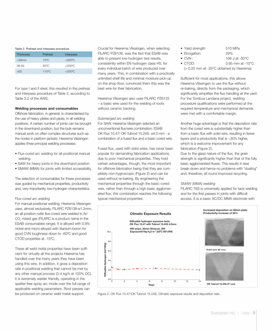
Another huge advantage is that the deposition rate from the cored wire is substantially higher than from a basic flux with solid wire, resulting in fewer layers and a productivity that is ~30% higher, which is a welcome improvement for any fabrication (Figure 2). Due to the glass nature of the flux, the grain strength is significantly higher than that of the fully basic agglomerated fluxes. This results in less break-down and hence no problems with “dusting” and, therefore, all round improved recycling.
SMAW (MMA) weldingFILARC 76S is universally applied for tack welding and for the first passes in joints with difficult access. It is a basic AC/DC MMA electrode with
For type I and II steel, this resulted in the preheat and interpass procedure of Table 2, according to Table 3.2 of the AWS.
Welding processes and consumables Offshore fabrication, in general, is characterised by the use of heavy plates and pipes, in all welding positions. A certain number of joints can be brought in the downhand position, but the bulk remains manual work on often complex structures such as the nodes in platform jackets. Heerema Vlissingen applies three principal welding processes:
• Flux-cored arc welding for all-positional manual welding.
• SAW for heavy joints in the downhand position• SMAW (MMA) for joints with limited accessibility.
The selection of consumables for these processes was guided by mechanical properties, productivity and, very importantly, low-hydrogen characteristics.
Flux-cored arc weldingFor manual positional welding, Heerema Vlissingen uses, almost exclusively, FILARC PZ6138-ø1.2mm, an all-position rutile flux-cored wire welded in Ar/CO2 mixed gas (FILARC is a product name in the ESAB consumables range). It is alloyed with 0.9% nickel and micro-alloyed with titanium-boron for good CVN toughness down to -60ºC and good CTOD properties at -15ºC.
These all weld metal properties have been suffi-cient for virtually all the projects Heerema has handled over the many years they have been using this wire. In addition, it gives a deposition rate in positional welding that cannot be met by any other manual process (3-4 kg/h at 100% DC). It is extremely welder friendly, operating in the spatter-free spray arc mode over the full range of applicable welding parameters. Root passes can be produced on ceramic weld metal support.
Table 2. Preheat and interpass procedure.
Thickness Preheat Interpass
<38mm 10ºC <200ºC
38-65 65ºC <200ºC
>65 110ºC <200ºC
Increased deposition on 50mm plateProductivity increase of 30%
Solid wire 48 runs
OK Tubrod 15.24S 37 runs
Figure 2. OK Flux 10.47/OK Tubrod 15.24S. Climatic exposure results and deposition rate.
0.0
2.0
4.0
6.0
8.0
10.0
0 2 4 6 8 10 12 14
Climatic Exposure Results
Diffusible hydrogen exposure testsOK Flux 10.47 with Tubrod 15.24S 4.0mm
Days
600 amps, 30mm Stickout, 30VExposure@19g H20 m-3 (250C 80%RH)
Diff
usib
le H
ydro
gen
(ml/
100g
)
.
10 - Svetsaren no. 1 - 2008
stiffener plates (Figure 4). This involves a vast amount of full penetration butt welds, as well as fillet welds, all performed with manual FCAW, using FILARC PZ6138. Where possible, root passes are deposited on ceramic weld metal support.
The welds connecting the pile sleeve to the shear plate involve a symmetrical double-sided K-joint in 51 mm thickness (openings angle 40 degrees, root gap 5mm, root face 1mm), welded with the SAW process, using the OK Flux 10.47/OK
Tubrod 15.24S flux/wire combination and ESAB A2 welding tractors. The root pass of these full-pen-etration welds is done with PZ6125, on ceramic backing, whereas sufficient thickness for the SAW process is obtained by a hot pass with PZ6138. In this stage, the construction can still be turned on roller beds, aided by contra weights, in order to use the productive SAW process on both sides.
Turning the construction is no longer possible when two pile sleeve-shear plate pairs – grit
Table 3. Overview of low-hydrogen consumables used for the Tombua Landana template.
ESAB consumables EN classification AWS Classification
FILARC PZ6125 758: T 42 6 1Ni B M 1H5 5.29: E71T-5G
FILARC PZ6138 758: T 46 5 1 Ni P M 1 H5 5.29: E81T1-Ni1MJ H4
OK Flux 10.47/ OK Tubrod 15.24S EN: S 46 5 AB T3Ni1 (AW) 5.23: F8A4-EC-G (AW)
FILARC 76S 499: E 42 6 Mn1Ni B 32 H5 5.5: E7018-G
good CVN properties down to -60°C and is CTOD tested in the AW and SR condition. It has a vast track record that dates back to the years when MMA was the standard for manual welding in offshore fabrication. FILARC 76S is low-hydrogen with low moisture absorption properties. It is supplied to Heerema Vlissingen in VacPac vacu-um packaging for ultimate protection.
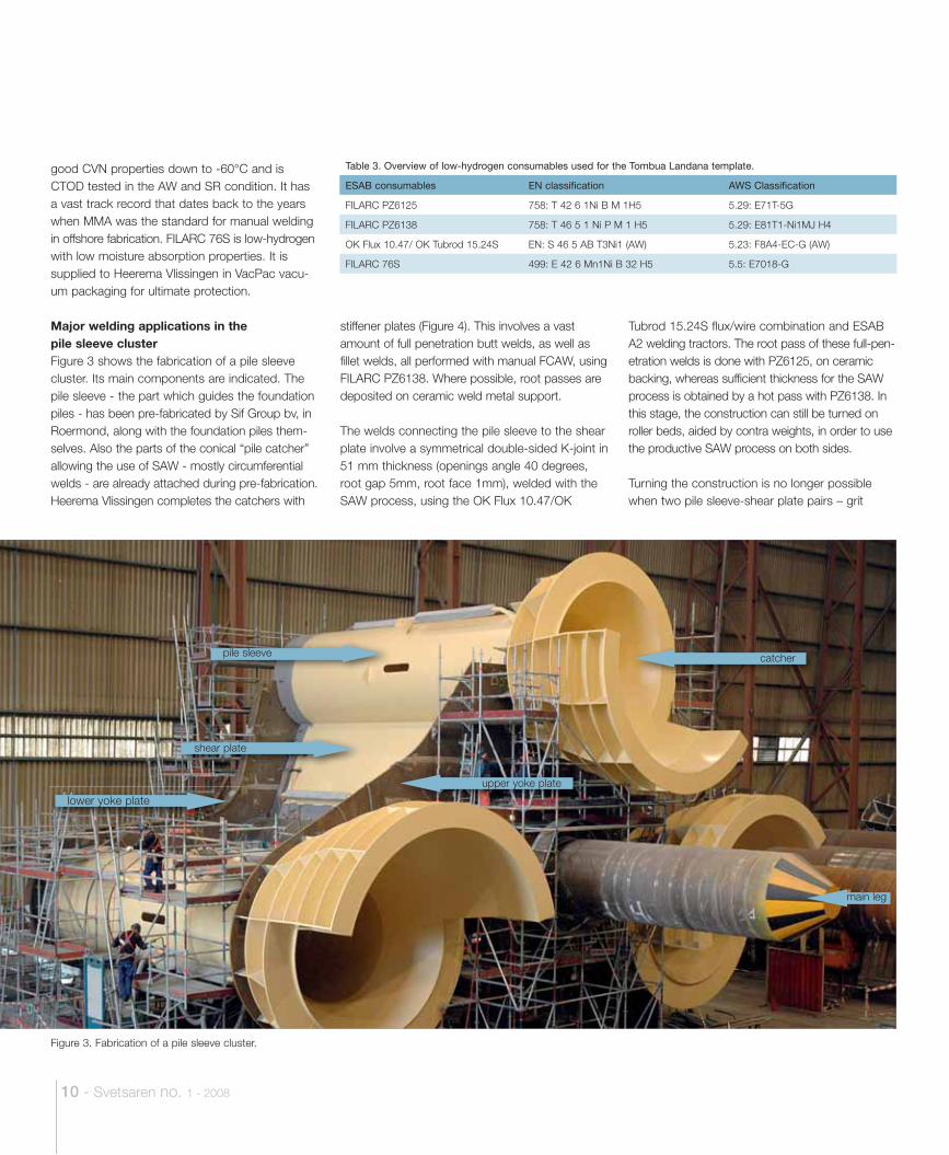
Major welding applications in the pile sleeve cluster Figure 3 shows the fabrication of a pile sleeve cluster. Its main components are indicated. The pile sleeve - the part which guides the foundation piles - has been pre-fabricated by Sif Group bv, in Roermond, along with the foundation piles them-selves. Also the parts of the conical “pile catcher” allowing the use of SAW - mostly circumferential welds - are already attached during pre-fabrication. Heerema Vlissingen completes the catchers with
Figure 3. Fabrication of a pile sleeve cluster.
lower yoke plate
shear plate
main leg
upper yoke plate
catcherpile sleeve

Svetsaren no. 1 - 2008 - 11
completed in the overhead position, using FILARC PZ6138 rutile cored-wire.
When the shear plate of the third, and last pile sleeve in a cluster, is connected to the main leg, the joint position is horizontal-vertical. The joint preparation is again a symmetrical K-joint welded
blasted and painted - are connected to the main leg. Here a combination of SAW for the down-hand side and FCAW for the overhead side is used (root FCAW on backing). The preparation is a 2/3 –1/3 K-joint, so that the larger part of the joint volume can be welded in the downhand position with the productive SAW process. The 1/3 side is
completely with the FCAW process, using FILARC PZ6138.
The upper and lower yoke plates are connected by means of manual FCAW. It concerns full penetration X- and K-welds with all welding positions occurring. Again PZ6138 is the main consumable (roots on ceramic backing).
TKY-joints in rowsThe rows - a network of heavy pipes connecting the four pile sleeve clusters – are pre-fabricated both indoors and outdoors. Their lay-out on the factory floor (Figure 6 ) exemplifies the great dimensional precision required.
The two columns on the left and right are not part of the structure. They have the same dimensions as the main legs of the pile sleeve clusters and precisely set the dimensions of the row, before (tack) welding. Permittable deviations here are as narrow as ± 1/4” (6 mm) horizontally and ± 1/8” (3 mm) vertically, requiring extreme accuracy. It is a procedure of virtually endless dimensional control. The same procedure is repeated during erection of the template (Figure 7), before rows are finally connected to the legs in the pile sleeve clusters.
All nodes (TKY-joints) are welded in the positions as they occur in figure 7 with FCAW using PZ6125 for the root and PZ6138 for filling. Figure 8 shows the FCAW welding on a special TKY-joint – the lifting trunniuns. These are used to attach the lifting cables onto the template during installation. Part of it is welded with SAW with OK Flux 10.47/OK Tubrod 15.24S (Figure 9).
Figure 4. FCAW of the sleeves – the part that catches
the foundation pile.
Figure 5. Submerged arc welding of a sheer plate onto
a pile sleeve.
Figure 6. Lay-out of a row on the factory floor before
welding – a precision job.
Figure 7. Erection of the template. All rows are first carefully positioned within the tolerances – with the help of temporary
columns (left) – before they are attached to the docking pins in the pile sleeve cluster (cluster visible in the background).
12 - Svetsaren no. 1 - 2008
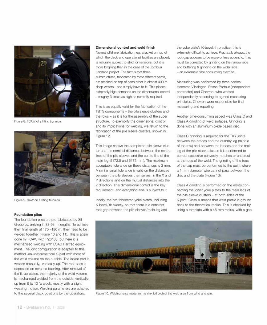
Foundation pilesThe foundation piles are pre-fabricated by Sif Group bv, arriving in 83-93 m lengths. To achieve their final length of 170 –190 m, they need to be welded together (Figure 10 and 11). This is again done by FCAW with PZ6138, but here it is mechanised welding with ESAB Railtrac equip-ment. The joint configuration is adapted to this method -an unsymmetrical X-joint with most of the weld volume on the outside. The inside part is welded manually, vertically-up. The root pass is deposited on ceramic backing. After removal of the fit-up plates, the majority of the weld volume is mechanised welded from the outside, vertically-up from 6 to 12 ‘o clock, mostly with a slight weaving motion. Welding parameters are adapted to the several clock positions by the operators.
Dimensional control and weld finish Normal offshore fabrication, eg, a jacket on top of which the deck and operational facilities are placed, is naturally, subject to strict dimensions, but it is more forgiving than in the case of the Tombua Landana project. The fact is that three substructures, fabricated by three different yards, are stacked on top of each other in almost 400 m deep waters - and simply have to fit. This places extremely high demands on the dimensional control – roughly 3 times as high as normally required.
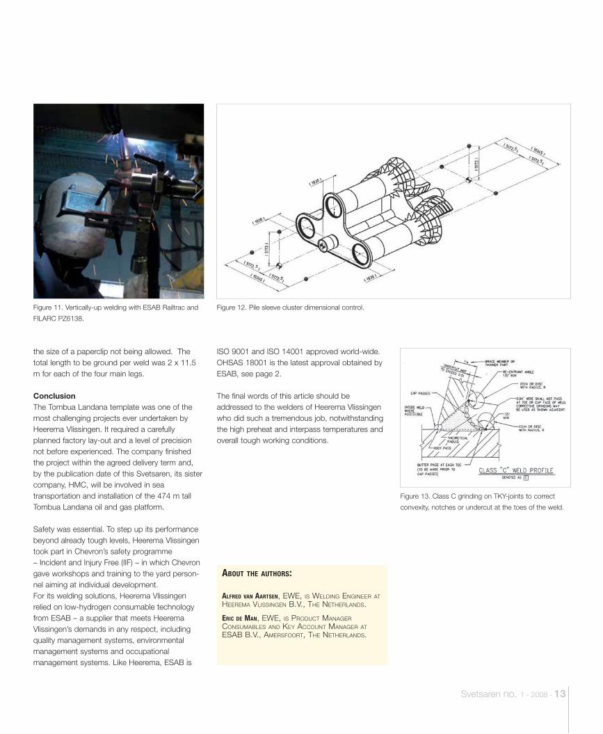
This is as equally valid for the fabrication of the TBT’s components – the pile sleeve clusters and the rows – as it is for the assembly of the super structure. To exemplify the dimensional control and its implications for welding, we return to the fabrication of the pile sleeve clusters, shown in Figure 12.
This image shows the completed pile sleeve clus-ter and the nominal distances between the centre lines of the pile sleeves and the centre line of the main leg (5172.5 and 5173 mm). The maximum acceptable tolerance on these distances is 3 mm. A similar small tolerance is valid on the distances between the pile sleeves themselves, in the X and Y directions and on the mutual distances into the Z direction. This dimensional control is the key requirement, and everything else is subject to it.
Ideally, the pre-fabricated yoke plates, including K-bevel, fit exactly, so that there is a constant root gap between the pile sleeves/main leg and
the yoke plate’s K-bevel. In practice, this is extremely difficult to achieve. Practically always, the root gap appears to be more or less eccentric. This must be corrected by grinding on the narrow side and buttering & grinding on the wider side– an extremely time consuming exercise.
Measuring was performed by three parties; Heerema Vlissingen, Passe-Partout (independent contractor) and Chevron, who worked independently according to agreed measuring principles. Chevron were responsible for final measuring and reporting.
Another time-consuming aspect was Class C and Class A grinding of weld surfaces. Grinding is done with an aluminium oxide based disc.
Class C grinding is required for the TKY joints between the braces and the dummy leg (middle of the row) and between the braces and the main leg of the pile sleeve cluster. It is performed to correct excessive convexity, notches or undercut at the toes of the weld. The grinding of the toes of the cap must be performed to the point where a 1 mm diameter wire cannot pass between the disc and the plate (Figure 13).
Class A grinding is performed on the welds con-necting the lower yoke plates to the main legs of the pile sleeve clusters – at both sides of the K-joint. Class A means that weld profile is ground back to the theoretical radius. This is checked by using a template with a 45 mm radius, with a gap
Figure 8. FCAW of a lifting trunnion.
Figure 9. SAW on a lifting trunnion.
Figure 10. Welding tents made from shrink foil protect the weld area from wind and rain.
Svetsaren no. 1 - 2008 - 13
ABOUT THE AUTHORS:
ALFRED VAN AARTSEN, EWE, IS WELDING ENGINEER AT HEEREMA VLISSINGEN B.V., THE NETHERLANDS.
ERIC DE MAN, EWE, IS PRODUCT MANAGER CONSUMABLES AND KEY ACCOUNT MANAGER AT ESAB B.V., AMERSFOORT, THE NETHERLANDS.
ISO 9001 and ISO 14001 approved world-wide. OHSAS 18001 is the latest approval obtained by ESAB, see page 2.
The final words of this article should be addressed to the welders of Heerema Vlissingen who did such a tremendous job, notwithstanding the high preheat and interpass temperatures and overall tough working conditions.
the size of a paperclip not being allowed. The total length to be ground per weld was 2 x 11.5 m for each of the four main legs.
ConclusionThe Tombua Landana template was one of the most challenging projects ever undertaken by Heerema Vlissingen. It required a carefully planned factory lay-out and a level of precision not before experienced. The company finished the project within the agreed delivery term and, by the publication date of this Svetsaren, its sister company, HMC, will be involved in sea transportation and installation of the 474 m tall Tombua Landana oil and gas platform.
Safety was essential. To step up its performance beyond already tough levels, Heerema Vlissingen took part in Chevron’s safety programme – Incident and Injury Free (IIF) – in which Chevron gave workshops and training to the yard person-nel aiming at individual development.For its welding solutions, Heerema Vlissingen relied on low-hydrogen consumable technology from ESAB – a supplier that meets Heerema Vlissingen’s demands in any respect, including quality management systems, environmental management systems and occupational management systems. Like Heerema, ESAB is
Figure 11. Vertically-up welding with ESAB Railtrac and
FILARC PZ6138.
Figure 12. Pile sleeve cluster dimensional control.
Figure 13. Class C grinding on TKY-joints to correct
convexity, notches or undercut at the toes of the weld.

Project Scope
Nemba
14” TL GAS EXPORT PIPELINE
East Kokongo
18” TL OIL EXPORT PIPELINE
MalongoTerminal
T-LProjectScope
Benguela Belize Platform
16” BBLT GAS EXPORT PIPELINE
Landana North via Lobito Subsea
Center C(3) Producers
(3) Water Injectors
T-L Drilling & Production
Platform30 wells
130 MBOPD Tombua SouthSubsea Center(6) Producers
(4) Water Injectors
Images on project description page (+map to be added)
Tower Top Section (TTS)
6,700 t
Tower Bottom Section (TBS)
29,200 t
Tower Base Template (TBT)
3,000 t
14 - Svetsaren no. 1 - 2008
Tombua Landana projectThis huge oil and gas platform is due to be operational by the third quarter of 2009 in the Tombua and Landana deep water development areas, off the coast of Angola. The main contractor is Daewoo Shipbuilding & Marine Engineering, on behalf of Cabinda Oil Company and its partners. It is the production centre in the development of the oil and gas reserves in block 14, in Angolan waters.The Tombua Landana development follows the installation of the Benguela Belize-platform, an integrated drilling and production platform for the development of the Benguela and Belize fields. It was the industry’s first application of compliant piled tower structural technology outside the Gulf of Mexico. At 512 m, it is among the world’s tallest man-made structures. The Tombua Landana project involves the construction of the drilling and production platform, a subsea centre of water injectors and producers and the installation and tie-in of two export pipelines that will connect the Tombua Landana drilling and production platform to the Benguela-Belize oil and gas pipeline transportation system. The Tombua Landana platform stands 474 m tall, nearly as high as her twin-sister in block 14. The platform engineering, fabrication and installation has been contracted to Daewoo Shipbuilding & Marine Engineering (DSME). DSME will build the the topside in Okpo, Korea and has subcontracted the tower top section (TTS) to Gulf Island Fabricators, the tower bottom section (TBS) to Gulf Marine Fabricators (USA); and the tower base template (TBT) to Heerema Vlissingen, The Netherlands.Transport of all substructures to Angola and installation has been subcontracted to Heerema Marine Contractors, a sister company of Heerema Vlissingen.
Taipei 101
1667ft (508m)
Petronas Towers
1483ft (452m)
Wells Fargo
994ft (303m)
Bank of America
781ft (238m)
The Gherkin
591ft (180m)
Tombua Landana
1554ft (474m)
Svetsaren no. 1 - 2008 - 15
The Bentini SpA GroupEstablished in the 1950s, the Bentini Group SpA, based in Faenza, Italy, expanded rapidly during post-war reconstruction, operating abroad as from 1976, and enjoying continuous growth and diversification in the civil and industrial plant-engineering sector, both as a main and sub contractor. It has a turnover of 150 million Euros and over 1200 employees, operating in France, Algeria, Libya and Nigeria. In Algeria, it has two daughter companies; Gepco SpA, a general
contractor in the oil and gas industry, and Benco SpA, a general construction contractor.
LNG tanksThe project consisted of three cryogenic tanks, each with a capacity 110,000m3. They are cylindrical in shape with a diameter of 80m and an overall height of 37m. The maximum liquid level inside the tank is 24m. The inner wall (in contact with the liquid gas) is constructed from X8Ni9 steel (EN 10028-4) - a 9% nickel steel,
BRUNO MALAGOLI, ESAB SPA., MESERO, ITALY.
Port of Marseille sees LNG storage tanks erected with ESAB welding technology.
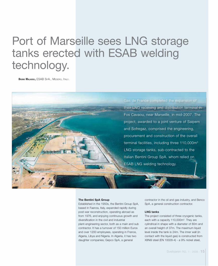
Gas de France completed the expansion of
their LNG receiving and distribution terminal in
Fos Cavaou, near Marseille, in mid-2007. The
project, awarded to a joint venture of Saipem
and Sofregaz, comprised the engineering,
procurement and construction of the overall
terminal facilities, including three 110,000m3
LNG storage tanks, sub-contracted to the
Italian Bentini Group SpA. whom relied on
ESAB LNG welding technology.
16 - Svetsaren no. 1 - 2008
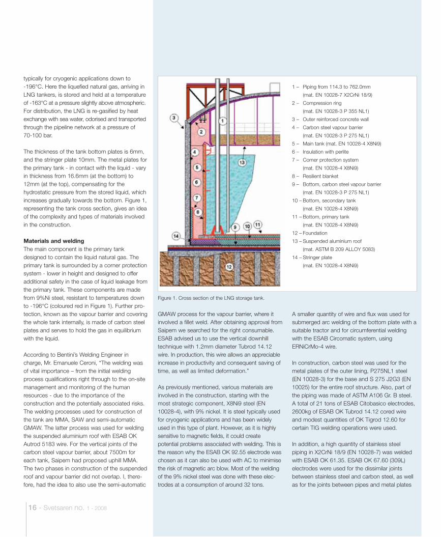
Figure 1. Cross section of the LNG storage tank.
typically for cryogenic applications down to -196°C. Here the liquefied natural gas, arriving in LNG tankers, is stored and held at a temperature of -163°C at a pressure slightly above atmospheric. For distribution, the LNG is re-gasified by heat exchange with sea water, odorised and transported through the pipeline network at a pressure of 70-100 bar.
The thickness of the tank bottom plates is 6mm, and the stringer plate 10mm. The metal plates for the primary tank - in contact with the liquid - vary in thickness from 16.6mm (at the bottom) to 12mm (at the top), compensating for the hydrostatic pressure from the stored liquid, which increases gradually towards the bottom. Figure 1, representing the tank cross section, gives an idea of the complexity and types of materials involved in the construction. Materials and weldingThe main component is the primary tank designed to contain the liquid natural gas. The primary tank is surrounded by a corner protection system - lower in height and designed to offer additional safety in the case of liquid leakage from the primary tank. These components are made from 9%Ni steel, resistant to temperatures down to -196°C (coloured red in Figure 1). Further pro-tection, known as the vapour barrier and covering the whole tank internally, is made of carbon steel plates and serves to hold the gas in equilibrium with the liquid.
According to Bentini’s Welding Engineer in charge, Mr. Emanuele Ceroni, “The welding was of vital importance – from the initial welding process qualifications right through to the on-site management and monitoring of the human resources - due to the importance of the construction and the potentially associated risks. The welding processes used for construction of the tank are MMA, SAW and semi-automatic GMAW. The latter process was used for welding the suspended aluminium roof with ESAB OK Autrod 5183 wire. For the vertical joints of the carbon steel vapour barrier, about 7500m for each tank, Saipem had proposed uphill MMA. The two phases in construction of the suspended roof and vapour barrier did not overlap. I, there-fore, had the idea to also use the semi-automatic
1 – Piping from 114.3 to 762.0mm
(mat. EN 10028-7 X2CrNi 18/9)
2 – Compression ring
(mat. EN 10028-3 P 355 NL1)
3 – Outer reinforced concrete wall
4 – Carbon steel vapour barrier
(mat. EN 10028-3 P 275 NL1)
5 – Main tank (mat. EN 10028-4 X8Ni9)
6 – Insulation with perlite
7 – Corner protection system
(mat. EN 10028-4 X8Ni9)
8 – Resilient blanket
9 – Bottom, carbon steel vapour barrier
(mat. EN 10028-3 P 275 NL1)
10 – Bottom, secondary tank
(mat. EN 10028-4 X8Ni9)
11 – Bottom, primary tank
(mat. EN 10028-4 X8Ni9)
12 – Foundation
13 – Suspended aluminium roof
(mat. ASTM B 209 ALLOY 5083)
14 – Stringer plate
(mat. EN 10028-4 X8Ni9)
GMAW process for the vapour barrier, where it involved a fillet weld. After obtaining approval from Saipem we searched for the right consumable. ESAB advised us to use the vertical downhill technique with 1.2mm diameter Tubrod 14.12 wire. In production, this wire allows an appreciable increase in productivity and consequent saving of time, as well as limited deformation.”
As previously mentioned, various materials are involved in the construction, starting with the most strategic component, X8Ni9 steel (EN 10028-4), with 9% nickel. It is steel typically used for cryogenic applications and has been widely used in this type of plant. However, as it is highly sensitive to magnetic fields, it could create potential problems associated with welding. This is the reason why the ESAB OK 92.55 electrode was chosen as it can also be used with AC to minimise the risk of magnetic arc blow. Most of the welding of the 9% nickel steel was done with these elec-trodes at a consumption of around 32 tons.
A smaller quantity of wire and flux was used for submerged arc welding of the bottom plate with a suitable tractor and for circumferential welding with the ESAB Circomatic system, using ERNiCrMo-4 wire.
In construction, carbon steel was used for the metal plates of the outer lining, P275NL1 steel (EN 10028-3) for the base and S 275 J2G3 (EN 10025) for the entire roof structure. Also, part of the piping was made of ASTM A106 Gr. B steel. A total of 21 tons of ESAB Citobasico electrodes, 2600kg of ESAB OK Tubrod 14.12 cored wire and modest quantities of OK Tigrod 12.60 for certain TIG welding operations were used.
In addition, a high quantity of stainless steel piping in X2CrNi 18/9 (EN 10028-7) was welded with ESAB OK 61.35. ESAB OK 67.60 (309L) electrodes were used for the dissimilar joints between stainless steel and carbon steel, as well as for the joints between pipes and metal plates
Svetsaren no. 1 - 2008 - 17
ABOUT THE AUTHOR:
NAAM FUNCTIE.
of the roof, involving an overall consumption of approximately 7-8000kg, in addition to 1400kg of ESAB OK Tigrod 16.10 rods.
Finally, the suspended aluminium roof (Figure 1), made of ASTM B209 alloy 5083, was welded with the GMAW process using 1.2mm and 2.4mm ESAB OK Autrod 5183 wire, totalconsumption being1500kg.
Co-operation “Our relationship with ESAB is excellent”, says Emanuele Ceroni. “Throughout the project, we received full support in terms of presence,assistance, advice, competence and innovation, as in the case of the OK Tubrod 14.12 wire. ESAB lives up to its image in quality, supply and service.”
ABOUT THE AUTHOR:
BRUNO MALAGOLI IS PRODUCT MANAGER CONSUMABLES AT ESAB SPA., MESERO, ITALY.
ESAB SAW technology crucial in the production of piles and transition pieces for the Q7 North Sea wind farm.
18 - Svetsaren no. 1 - 2008
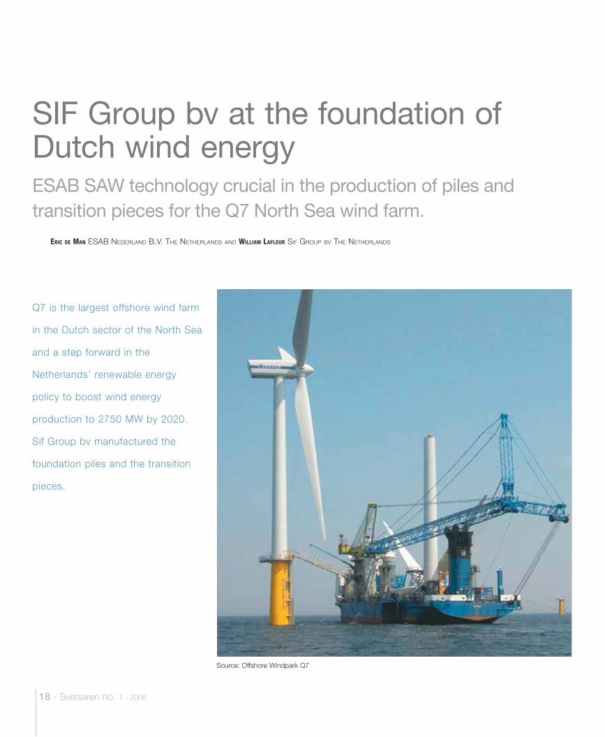
Q7 is the largest offshore wind farm
in the Dutch sector of the North Sea
and a step forward in the
Netherlands’ renewable energy
policy to boost wind energy
production to 2750 MW by 2020.
Sif Group bv manufactured the
foundation piles and the transition
pieces.
ERIC DE MAN ESAB NEDERLAND B.V. THE NETHERLANDS AND WILLIAM LAFLEUR SIF GROUP BV THE NETHERLANDS
SIF Group bv at the foundation of Dutch wind energy
Source: Offshore Windpark Q7
Svetsaren no. 1 - 2008 - 19
Acknowledgement.We thank the management of Sif Group bv for facilitating our visit to the production site.
The Q7 projectThe Q7 offshore wind farm has been built some 23 km offshore from IJmuiden, in block Q7 of the Dutch continental shelf. It is unique in the sense that it is the world’s first located at such a dis-tance from the coast (outside the 12-mile zone) and in deeper waters than ever before (19-24m).
This was one of the reasons why its owners, sustainable energy group Econcern, and energy company ENECO Energie, selected the proven technology of the Vestas V-80 2.0 MW turbines. The project comprises 60 wind turbines with a total capacity of 120 MW.
Under the Kyoto Protocol, The Netherlands agreed to reduce greenhouse gas emissions, in the period 2008-2012, by 6% relative to the 1990 levels. The Q7 project will contribute a reduction of 225,000 tonnes of CO2 emission, annualy.
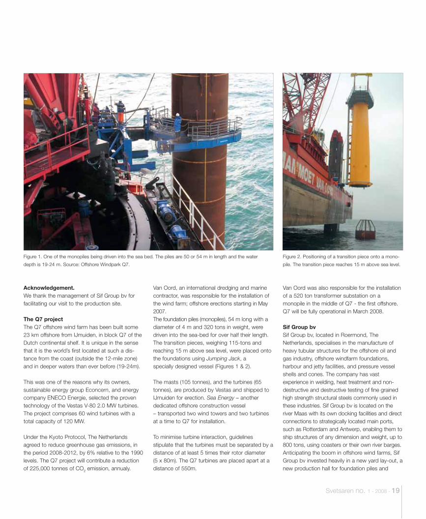
Van Oord, an international dredging and marine contractor, was responsible for the installation of the wind farm; offshore erections starting in May 2007. The foundation piles (monopiles), 54 m long with a diameter of 4 m and 320 tons in weight, were driven into the sea-bed for over half their length. The transition pieces, weighing 115-tons and reaching 15 m above sea level, were placed onto the foundations using Jumping Jack, a specially designed vessel (Figures 1 & 2).
The masts (105 tonnes), and the turbines (65 tonnes), are produced by Vestas and shipped to IJmuiden for erection. Sea Energy – another dedicated offshore construction vessel – transported two wind towers and two turbines at a time to Q7 for installation.
To minimise turbine interaction, guidelines stipulate that the turbines must be separated by a distance of at least 5 times their rotor diameter (5 x 80m). The Q7 turbines are placed apart at a distance of 550m.
Van Oord was also responsible for the installation of a 520 ton transformer substation on a monopile in the middle of Q7 - the first offshore. Q7 will be fully operational in March 2008. Sif Group bvSif Group bv, located in Roermond, The Netherlands, specialises in the manufacture of heavy tubular structures for the offshore oil and gas industry, offshore windfarm foundations, harbour and jetty facilities, and pressure vessel shells and cones. The company has vast experience in welding, heat treatment and non-destructive and destructive testing of fine grained high strength structural steels commonly used in these industries. Sif Group bv is located on the river Maas with its own docking facilities and direct connections to strategically located main ports, such as Rotterdam and Antwerp, enabling them to ship structures of any dimension and weight, up to 800 tons, using coasters or their own river barges. Anticipating the boom in offshore wind farms, Sif Group bv invested heavily in a new yard lay-out, a new production hall for foundation piles and
Figure 2. Positioning of a transition piece onto a mono-
pile. The transition piece reaches 15 m above sea level.
Figure 1. One of the monopiles being driven into the sea bed. The piles are 50 or 54 m in length and the water
depth is 19-24 m. Source: Offshore Windpark Q7.
20 - Svetsaren no. 1 - 2008
modern production lines - a process that is still ongoing. This policy has been extremely success-ful, judging by the impressive list of offshore wind farms in Western Europe in which the company has been involved. More than 80% of the installed offshore wind farms rely on steel foundations fabricated by Sif Group bv, amongst them the Horns Rev project in Denmark (the second largest farm to date) and the Q7 project.
Sif Group bv maintains an effective quality management system certified in accordance with the ISO 9001: 2000 standard and with the implementation of EN-ISO 3834-2 comprehensive quality requirements for welding. Additional international approvals and authorisations include:
• Structural tubulars: API Spec. 2B• Pressure vessel parts: ASME U stamp, ASME
U2 stamp, ASME S stamp, PED 97/23 • Dynamically loaded Steel Structures:
DIN 18800-7 Class E – Ü stamp.
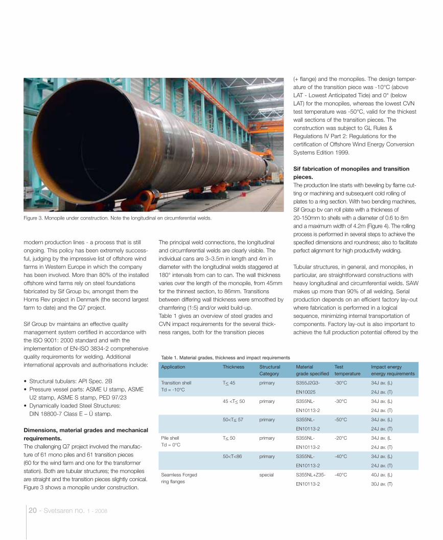
Dimensions, material grades and mechanical requirements.The challenging Q7 project involved the manufac-ture of 61 mono piles and 61 transition pieces (60 for the wind farm and one for the transformer station). Both are tubular structures; the monopiles are straight and the transition pieces slightly conical. Figure 3 shows a monopile under construction.
The principal weld connections, the longitudinal and circumferential welds are clearly visible. The individual cans are 3–3.5m in length and 4m in diameter with the longitudinal welds staggered at 180° intervals from can to can. The wall thickness varies over the length of the monopile, from 45mm for the thinnest section, to 86mm. Transitions between differing wall thickness were smoothed by chamfering (1:5) and/or weld build-up.Table 1 gives an overview of steel grades and CVN impact requirements for the several thick-ness ranges, both for the transition pieces
(+ flange) and the monopiles. The design temper-ature of the transition piece was -10°C (above LAT - Lowest Anticipated Tide) and 0° (below LAT) for the monopiles, whereas the lowest CVN test temperature was -50°C, valid for the thickest wall sections of the transition pieces. The construction was subject to GL Rules & Regulations IV Part 2: Regulations for the certification of Offshore Wind Energy Conversion Systems Edition 1999.
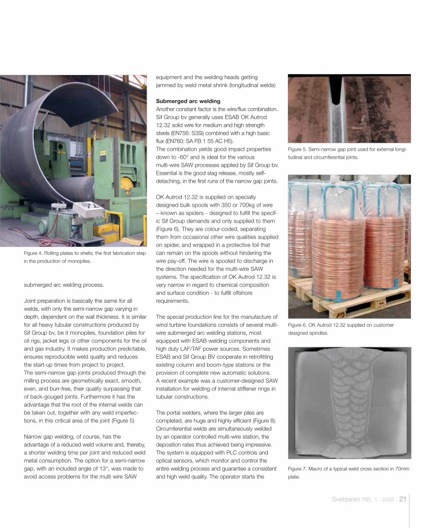
Sif fabrication of monopiles and transition pieces.The production line starts with beveling by flame cut-ting or machining and subsequent cold rolling of plates to a ring section. With two bending machines, Sif Group bv can roll plate with a thickness of 20-150mm to shells with a diameter of 0.6 to 8m and a maximum width of 4.2m (Figure 4). The rolling process is performed in several steps to achieve the specified dimensions and roundness; also to facilitate perfect alignment for high productivity welding.
Tubular structures, in general, and monopiles, in particular, are straightforward constructions with heavy longitudinal and circumferential welds. SAW makes up more than 90% of all welding. Serial production depends on an efficient factory lay-out where fabrication is performed in a logical sequence, minimizing internal transportation of components. Factory lay-out is also important to achieve the full production potential offered by the
Figure 3. Monopile under construction. Note the longitudinal en circumferential welds.
Table 1. Material grades, thickness and impact requirements
Application Thickness Structural Category
Materialgrade specified
Test temperature
Impact energy energy requirements
Transition shellTd = -10°C
T< 45 primary S355J2G3- -30°C 34J av. (L)
EN10025 24J av. (T)
45 <T< 50 primary S355NL- -30°C 34J av. (L)
EN10113-2 24J av. (T)
50<T< 57 primary S355NL- -50°C 34J av. (L)
EN10113-2 24J av. (T)
Pile shellTd = 0°C
T< 50 primary S355NL- -20°C 34J av. (L
EN10113-2 24J av. (T)
50<T<86 primary S355NL- -40°C 34J av. (L)
EN10113-2 24J av. (T)
Seamless Forged ring flanges
special S355NL+Z35- -40°C 40J av. (L)
EN10113-2 30J av. (T)
Svetsaren no. 1 - 2008 - 21
submerged arc welding process.
Joint preparation is basically the same for all welds, with only the semi-narrow gap varying in depth, dependent on the wall thickness. It is similar for all heavy tubular constructions produced by Sif Group bv, be it monopiles, foundation piles for oil rigs, jacket legs or other components for the oil and gas industry. It makes production predictable, ensures reproducible weld quality and reduces the start-up times from project to project.The semi-narrow gap joints produced through the milling process are geometrically exact, smooth, even, and burr-free, their quality surpassing that of back-gouged joints. Furthermore it has the advantage that the root of the internal welds can be taken out, together with any weld imperfec-tions, in this critical area of the joint (Figure 5) Narrow gap welding, of course, has theadvantage of a reduced weld volume and, thereby, a shorter welding time per joint and reduced weld metal consumption. The option for a semi-narrow gap, with an included angle of 13°, was made to avoid access problems for the multi wire SAW
equipment and the welding heads getting jammed by weld metal shrink (longitudinal welds)
Submerged arc weldingAnother constant factor is the wire/flux combination. Sif Group bv generally uses ESAB OK Autrod 12.32 solid wire for medium and high strength steels (EN756: S3Si) combined with a high basic flux (EN760: SA FB 1 55 AC H5). The combination yields good impact properties down to -60° and is ideal for the various multi-wire SAW processes applied by Sif Group bv. Essential is the good slag release, mostly self-detaching, in the first runs of the narrow gap joints.
OK Autrod 12.32 is supplied on specially designed bulk spools with 350 or 700kg of wire – known as spiders - designed to fulfill the specif-ic Sif Group demands and only supplied to them (Figure 6). They are colour-coded, separating them from occasional other wire qualities supplied on spider, and wrapped in a protective foil that can remain on the spools without hindering the wire pay-off. The wire is spooled to discharge in the direction needed for the multi-wire SAW systems. The specification of OK Autrod 12.32 is very narrow in regard to chemical composition and surface condition - to fulfill offshorerequirements.
The special production line for the manufacture of wind turbine foundations consists of several multi-wire submerged arc welding stations, most equipped with ESAB welding components and high duty LAF/TAF power sources. Sometimes ESAB and Sif Group BV cooperate in retrofitting existing column and boom-type stations or the provision of complete new automatic solutions.A recent example was a customer-designed SAW installation for welding of internal stiffener rings in tubular constructions.
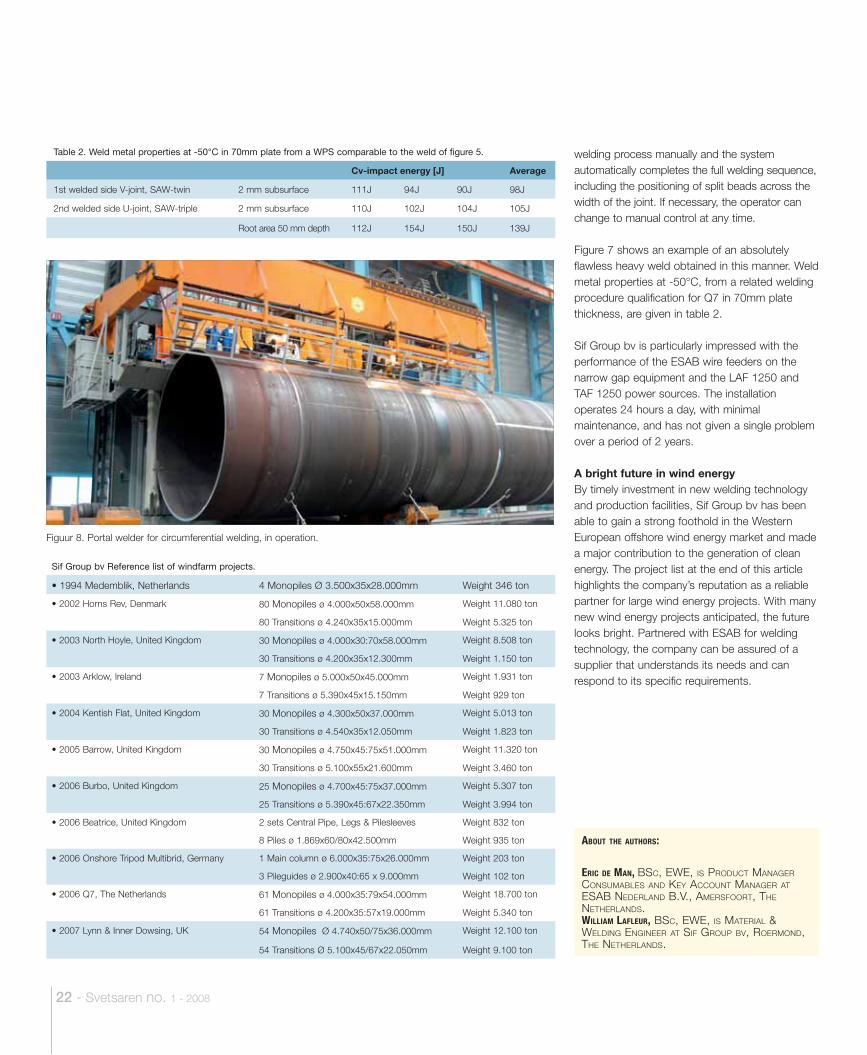
The portal welders, where the larger piles are completed, are huge and highly efficient (Figure 8). Circumferential welds are simultaneously welded by an operator controlled multi-wire station, the deposition rates thus achieved being impressive. The system is equipped with PLC controls and optical sensors, which monitor and control the entire welding process and guarantee a consistent and high weld quality. The operator starts the
Figure 4. Rolling plates to shells; the first fabrication step
in the production of monopiles.
Figure 6. OK Autrod 12.32 supplied on customer
designed spindles.
Figure 5. Semi-narrow gap joint used for external longi-
tudinal and circumferential joints.
Figure 7. Macro of a typical weld cross section in 70mm
plate.
22 - Svetsaren no. 1 - 2008
welding process manually and the system automatically completes the full welding sequence, including the positioning of split beads across the width of the joint. If necessary, the operator can change to manual control at any time.
Figure 7 shows an example of an absolutely flawless heavy weld obtained in this manner. Weld metal properties at -50°C, from a related welding procedure qualification for Q7 in 70mm plate thickness, are given in table 2.
Sif Group bv is particularly impressed with the performance of the ESAB wire feeders on the narrow gap equipment and the LAF 1250 and TAF 1250 power sources. The installation operates 24 hours a day, with minimal maintenance, and has not given a single problem over a period of 2 years.
A bright future in wind energyBy timely investment in new welding technology and production facilities, Sif Group bv has been able to gain a strong foothold in the Western European offshore wind energy market and made a major contribution to the generation of clean energy. The project list at the end of this article highlights the company’s reputation as a reliable partner for large wind energy projects. With many new wind energy projects anticipated, the future looks bright. Partnered with ESAB for welding technology, the company can be assured of a supplier that understands its needs and can respond to its specific requirements.
Figuur 8. Portal welder for circumferential welding, in operation.
Sif Group bv Reference list of windfarm projects.
• 1994 Medemblik, Netherlands 4 Monopiles Ø 3.500x35x28.000mm Weight 346 ton
• 2002 Horns Rev, Denmark 80 Monopiles ø 4.000x50x58.000mm Weight 11.080 ton
80 Transitions ø 4.240x35x15.000mm Weight 5.325 ton
• 2003 North Hoyle, United Kingdom 30 Monopiles ø 4.000x30:70x58.000mm Weight 8.508 ton
30 Transitions ø 4.200x35x12.300mm Weight 1.150 ton
• 2003 Arklow, Ireland 7 Monopiles ø 5.000x50x45.000mm Weight 1.931 ton
7 Transitions ø 5.390x45x15.150mm Weight 929 ton
• 2004 Kentish Flat, United Kingdom 30 Monopiles ø 4.300x50x37.000mm Weight 5.013 ton
30 Transitions ø 4.540x35x12.050mm Weight 1.823 ton
• 2005 Barrow, United Kingdom 30 Monopiles ø 4.750x45:75x51.000mm Weight 11.320 ton
30 Transitions ø 5.100x55x21.600mm Weight 3.460 ton
• 2006 Burbo, United Kingdom 25 Monopiles ø 4.700x45:75x37.000mm Weight 5.307 ton
25 Transitions ø 5.390x45:67x22.350mm Weight 3.994 ton
• 2006 Beatrice, United Kingdom 2 sets Central Pipe, Legs & Pilesleeves Weight 832 ton
8 Piles ø 1.869x60/80x42.500mm Weight 935 ton
• 2006 Onshore Tripod Multibrid, Germany 1 Main column ø 6.000x35:75x26.000mm Weight 203 ton
3 Pileguides ø 2.900x40:65 x 9.000mm Weight 102 ton
• 2006 Q7, The Netherlands 61 Monopiles ø 4.000x35:79x54.000mm Weight 18.700 ton
61 Transitions ø 4.200x35:57x19.000mm Weight 5.340 ton
• 2007 Lynn & Inner Dowsing, UK 54 Monopiles Ø 4.740x50/75x36.000mm Weight 12.100 ton
54 Transitions Ø 5.100x45/67x22.050mm Weight 9.100 ton
Table 2. Weld metal properties at -50°C in 70mm plate from a WPS comparable to the weld of figure 5.
Cv-impact energy [J] Average
1st welded side V-joint, SAW-twin 2 mm subsurface 111J 94J 90J 98J
2nd welded side U-joint, SAW-triple 2 mm subsurface 110J 102J 104J 105J
Root area 50 mm depth 112J 154J 150J 139J
ABOUT THE AUTHORS:
ERIC DE MAN, BSC, EWE, IS PRODUCT MANAGER CONSUMABLES AND KEY ACCOUNT MANAGER AT ESAB NEDERLAND B.V., AMERSFOORT, THE NETHERLANDS.WILLIAM LAFLEUR, BSC, EWE, IS MATERIAL & WELDING ENGINEER AT SIF GROUP BV, ROERMOND, THE NETHERLANDS.
Svetsaren no. 1 - 2008 - 23
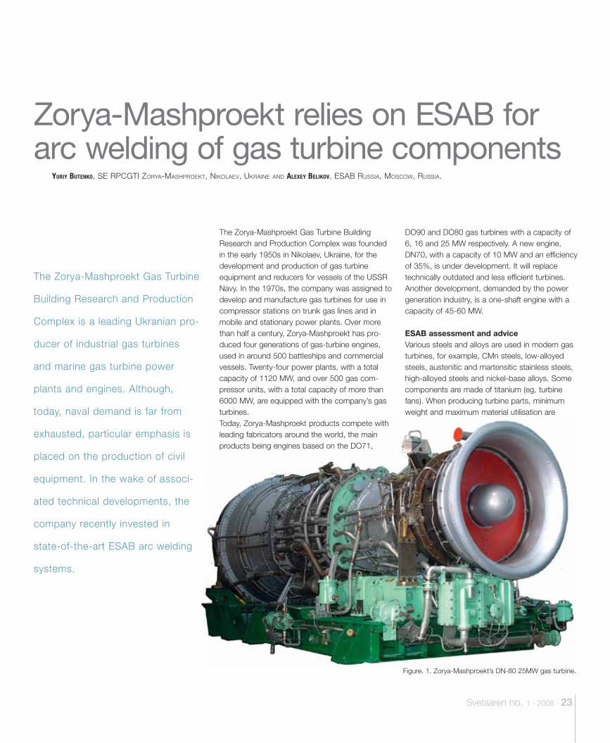
The Zorya-Mashproekt Gas Turbine Building Research and Production Complex was founded in the early 1950s in Nikolaev, Ukraine, for the development and production of gas turbine equipment and reducers for vessels of the USSR Navy. In the 1970s, the company was assigned to develop and manufacture gas turbines for use in compressor stations on trunk gas lines and in mobile and stationary power plants. Over more than half a century, Zorya-Mashproekt has pro-duced four generations of gas-turbine engines, used in around 500 battleships and commercial vessels. Twenty-four power plants, with a total capacity of 1120 MW, and over 500 gas com-pressor units, with a total capacity of more than 6000 MW, are equipped with the company’s gas turbines. Today, Zorya-Mashproekt products compete with leading fabricators around the world, the main products being engines based on the DO71,
DO90 and DO80 gas turbines with a capacity of 6, 16 and 25 MW respectively. A new engine, DN70, with a capacity of 10 MW and an efficiency of 35%, is under development. It will replace technically outdated and less efficient turbines. Another development, demanded by the power generation industry, is a one-shaft engine with a capacity of 45-60 MW.
ESAB assessment and adviceVarious steels and alloys are used in modern gas turbines, for example, CMn steels, low-alloyed steels, austenitic and martensitic stainless steels, high-alloyed steels and nickel-base alloys. Some components are made of titanium (eg, turbine fans). When producing turbine parts, minimum weight and maximum material utilisation are
The Zorya-Mashproekt Gas Turbine
Building Research and Production
Complex is a leading Ukranian pro-
ducer of industrial gas turbines
and marine gas turbine power
plants and engines. Although,
today, naval demand is far from
exhausted, particular emphasis is
placed on the production of civil
equipment. In the wake of associ-
ated technical developments, the
company recently invested in
state-of-the-art ESAB arc welding
systems.
YURIY BUTENKO, SE RPCGTI ZORYA-MASHPROEKT, NIKOLAEV, UKRAINE AND ALEXEY BELIKOV, ESAB RUSSIA, MOSCOW, RUSSIA.
Zorya-Mashproekt relies on ESAB for arc welding of gas turbine components
Figure. 1. Zorya-Mashproekt’s DN-80 25MW gas turbine.
24 - Svetsaren no. 1 - 2008
important factors. Most parts are manufactured using welding technologies and the welded joint is often the crucial element defining the operation-al capability of the part. Also, with the limited weldability of some of the materials used, the most important consideration for the welding specialist is the selection of the appropriate and most efficient welding process, equipment and consumables.
Electron-beam welding is the principal welding process used in the fabrication of gas-turbine engines. It is performed under vacuum, which protects the weld pool and facilitates weld metal strength, deformation being minimal due to the
highly concentrated heat source. However, for many components, arc welding processes are preferred.
Co-operation with ESAB began in 1995, when company management set the task of increasing production output and reducing welding costs. ESAB specialists carried out a technical audit of the welding methods used in production. Its conclusion was that, without up-to-date arc welding technologies - MMA and manual TIG welding being the main arc welding processes – results were high weld metal consumption and unnecessarily low overall productivity. Also, repair rates were high because the superior weld quality standard was hard to meet - even by qualified welders.
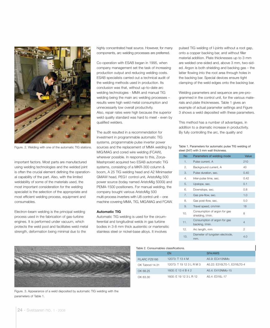
The audit resulted in a recommendation for investment in programmable automatic TIG systems, programmable pulse inverter power sources and the replacement of MMA welding by MIG/MAG and cored wire welding (FCAW), wherever possible. In response to this, Zorya-Mashproekt acquired two ESAB automatic TIG systems, consisting of a MKR-300 column & boom, A 25 TIG welding head and A2 Minimaster GMAW head, PEG1 control unit, AristoMig 500 power source (today named AristoMig 5000i) and PEMA-1500 positioners. For manual welding, the company bought various AristoMig 500 multi-process inverters with U8 control unit – one machine covering MMA, TIG, MIG/MAG and FCAW.
Automatic TIGAutomatic TIG welding is used for the circum-ferential and longitudinal welds in gas turbine bodies in 3-8 mm thick austenitic or martensitic stainless steel or nickel-base alloys. It involves
pulsed TIG welding of I-joints without a root gap, onto a copper backing bar, and without filler material addition. Plate thicknesses up to 3 mm are welded one-sided and, above 3 mm, two-sid-ed. Argon is both shielding and backing gas – the latter flowing into the root area through holes in the backing bar. Special devices ensure tight clamping of the weld edges onto the backing bar.
Welding parameters and sequence are pre-pro-grammed in the control unit, for the various mate-rials and plate thicknesses. Table 1 gives an example of actual parameter settings and Figure 3 shows a weld deposited with these parameters.
This method has a number of advantages, in addition to a dramatic increase in productivity. By fully controlling the arc, the quality and
Table 1. Parameters for automatic pulse TIG welding of steel (347) with 3 mm wall thickness.
No Parameters of welding mode Value
1. Pulse current, A 210
2. Background current, A 40
3. Pulse duration, sec. 0.40
4. Inter-pulse time, sec. 0.42
5. Upslope, sec. 0.1
6. Downslope, sec. 0.8
7. Gas pre-flow, sec. 1.0
8. Gas post-flow, sec. 5.0
9. Travel speed, cm/min 18
10.Consumption of argon for gas shielding, l/min.
8
11.Consumption of argon for gas backing, l/min.
4
12. Arc length, mm 2
13.Diameter of tungsten electrode, mm.
4.0
Table 2. Consumables classifications.
EN SFA/AWS
FILARC PZ6166 12073: T 13 4 M A5.9: EC410NiMo
OK Tubrod 14.31 12073: T 19 12 3 L R M 3 A5.22: E316LT0-1, E316LT0-4
OK 68.25 1600: E 13 4 B 4 2 A5.4: E410NiMo-15
OK 63.30 1600: E 19 12 3 L R 12 A5.4: E316L-17
Figure. 2. Welding with one of the automatic TIG stations.
Figure. 3. Appearance of a weld deposited by automatic TIG welding with the
parameters of Table 1.
Svetsaren no. 1 - 2008 - 25
appearance of the weld become consistent and repeatable. Also, the lower heat input from pulse welding gives lower welding stresses and consequently lower deformation, as well as a reduced risk of hot cracking in sensitive materials.
As mentioned, the method allows welding without a root gap and without filler materials, but it places high requirements on the preparation of the weld edges:
• the cut, achieved by laser cutting, must be exactly perpendicular to the surface;
• after cutting, machining of the edges is required to a depth of 0.5 mm to remove the oxide film;
• the joint area must be cleaned to metal shine (10-15 mm from both edges);
• the plate edges must be square along the full length, without edge rounding and bevels;
• the root gap may not exceed 0.2 mm;• the displacement and thickness variation of the
plate edges may not exceed 10% of the nominal thickness;
• run-on and run-off plates must be of the same material and thickness as the base metal.
• the axis of the joint should coincide with the axis of the forming groove.
Cored wire welding Flux- and metal-cored wires are widely used for manual and mechanised welding. FILARC PZ6166 metal-cored wire, sometimes combined with the MMA electrode OK 68.25, is used for components in martensitic stainless steel. For
austenitic 18Cr-9Ni grades, the company uses OK Tubrod 14.31 rutile flux-cored wire and the MMA electrode OK 63.30 (Table 2).
An example of cored wire welding with FILARC PZ6166 are the rings for the turbine outlet. These are in martensitic stainless steel 20-13 (410) with 14-20 mm wall thickness, a diameter 600-800 mm and a height up to 250 mm. After having rolled a bar to a ring, the ring is closed by manual welding in the downhand position.
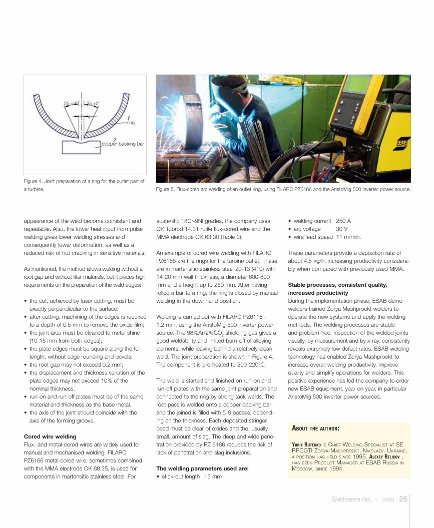
Welding is carried out with FILARC PZ6116 -1.2 mm, using the AristoMig 500 inverter power source. The 98%Ar/2%CO2 shielding gas gives a good weldability and limited burn-off of alloying elements, while leaving behind a relatively clean weld. The joint preparation is shown in Figure 4. The component is pre-heated to 200-220°C.
The weld is started and finished on run-on and run-off plates with the same joint preparation and connected to the ring by strong tack welds. The root pass is welded onto a copper backing bar and the joined is filled with 5-8 passes, depend-ing on the thickness. Each deposited stringer bead must be clear of oxides and the, usually small, amount of slag. The deep and wide pene-tration provided by PZ 6166 reduces the risk of lack of penetration and slag inclusions.
The welding parameters used are:• stick-out length 15 mm
• welding current 250 A • arc voltage 30 V • wire feed speed 11 m/min.
These parameters provide a deposition rate of about 4.5 kg/h, increasing productivity considera-bly when compared with previously used MMA.
Stable processes, consistent quality, increased productivityDuring the implementation phase, ESAB demo welders trained Zorya Mashproekt welders to operate the new systems and apply the welding methods. The welding processes are stable and problem-free. Inspection of the welded joints visually, by measurement and by x-ray, consistently reveals extremely low defect rates. ESAB welding technology has enabled Zorya Mashproekt to increase overall welding productivity, improve quality and simplify operations for welders. This positive experience has led the company to order new ESAB equipment, year on year, in particular AristoMig 500 inverter power sources.
Figure 4. Joint preparation of a ring for the outlet part of
a turbine.
ring
copper backing bar
Figure 5. Flux-cored arc welding of an outlet ring, using FILARC PZ6166 and the AristoMig 500 inverter power source.
ABOUT THE AUTHOR:
YURIY BUTENKO IS CHIEF WELDING SPECIALIST AT SE RPCGTI ZORYA-MASHPROEKT, NIKOLAEV, UKRAINE, A POSITION HAS HELD SINCE 1995. ALEXEY BELIKOV , HAS BEEN PRODUCT MANAGER AT ESAB RUSSIA IN MOSCOW, SINCE 1994.
25 ±2° 25 ±2°
4+1
26 - Svetsaren no. 1 - 2008
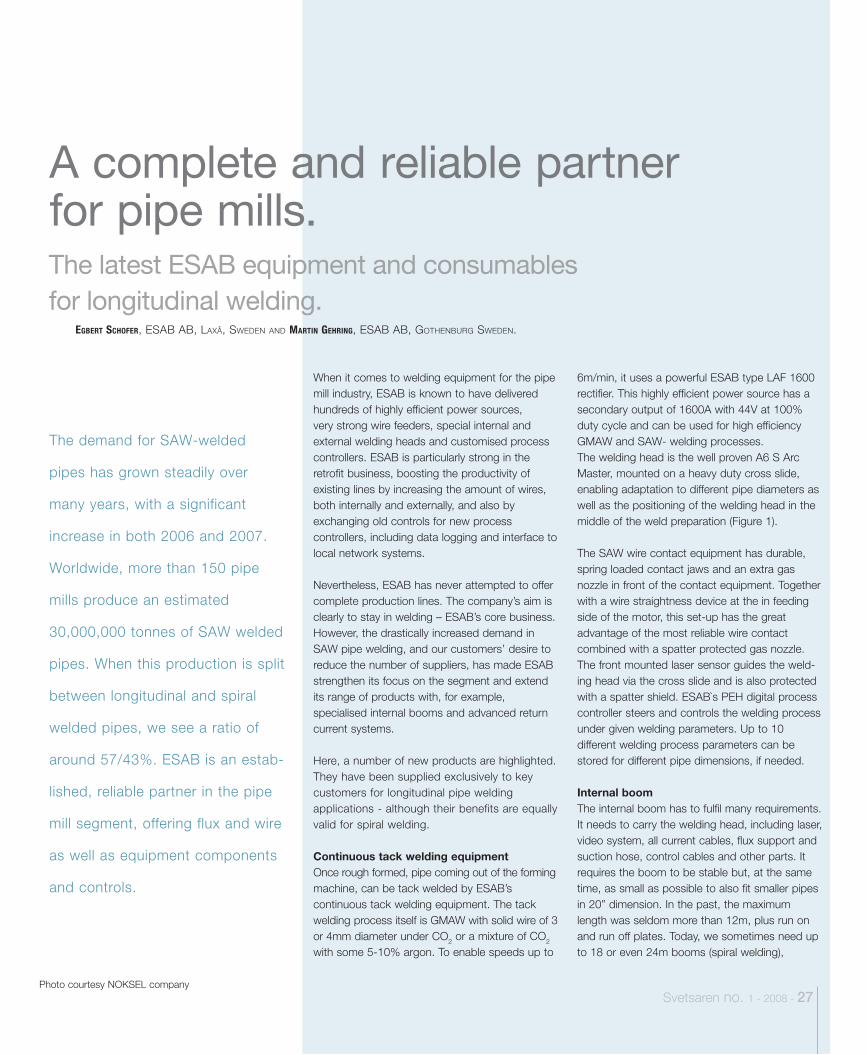
The latest ESAB equipment and consumables for longitudinal welding.
Svetsaren no. 1 - 2008 - 27 Photo courtesy NOKSEL company
When it comes to welding equipment for the pipe mill industry, ESAB is known to have delivered hundreds of highly efficient power sources, very strong wire feeders, special internal and external welding heads and customised process controllers. ESAB is particularly strong in the retrofit business, boosting the productivity of existing lines by increasing the amount of wires, both internally and externally, and also by exchanging old controls for new process controllers, including data logging and interface to local network systems.
Nevertheless, ESAB has never attempted to offer complete production lines. The company’s aim is clearly to stay in welding – ESAB’s core business. However, the drastically increased demand in SAW pipe welding, and our customers’ desire to reduce the number of suppliers, has made ESAB strengthen its focus on the segment and extend its range of products with, for example, specialised internal booms and advanced return current systems.
Here, a number of new products are highlighted. They have been supplied exclusively to key customers for longitudinal pipe welding applications - although their benefits are equally valid for spiral welding.
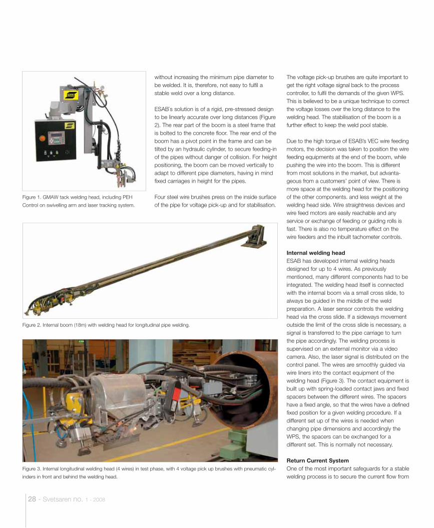
Continuous tack welding equipmentOnce rough formed, pipe coming out of the forming machine, can be tack welded by ESAB’s continuous tack welding equipment. The tack welding process itself is GMAW with solid wire of 3 or 4mm diameter under CO2 or a mixture of CO2 with some 5-10% argon. To enable speeds up to
6m/min, it uses a powerful ESAB type LAF 1600 rectifier. This highly efficient power source has a secondary output of 1600A with 44V at 100% duty cycle and can be used for high efficiency GMAW and SAW- welding processes.The welding head is the well proven A6 S Arc Master, mounted on a heavy duty cross slide, enabling adaptation to different pipe diameters as well as the positioning of the welding head in the middle of the weld preparation (Figure 1).
The SAW wire contact equipment has durable, spring loaded contact jaws and an extra gas nozzle in front of the contact equipment. Together with a wire straightness device at the in feeding side of the motor, this set-up has the great advantage of the most reliable wire contact combined with a spatter protected gas nozzle. The front mounted laser sensor guides the weld-ing head via the cross slide and is also protected with a spatter shield. ESAB`s PEH digital process controller steers and controls the welding process under given welding parameters. Up to 10 different welding process parameters can be stored for different pipe dimensions, if needed.
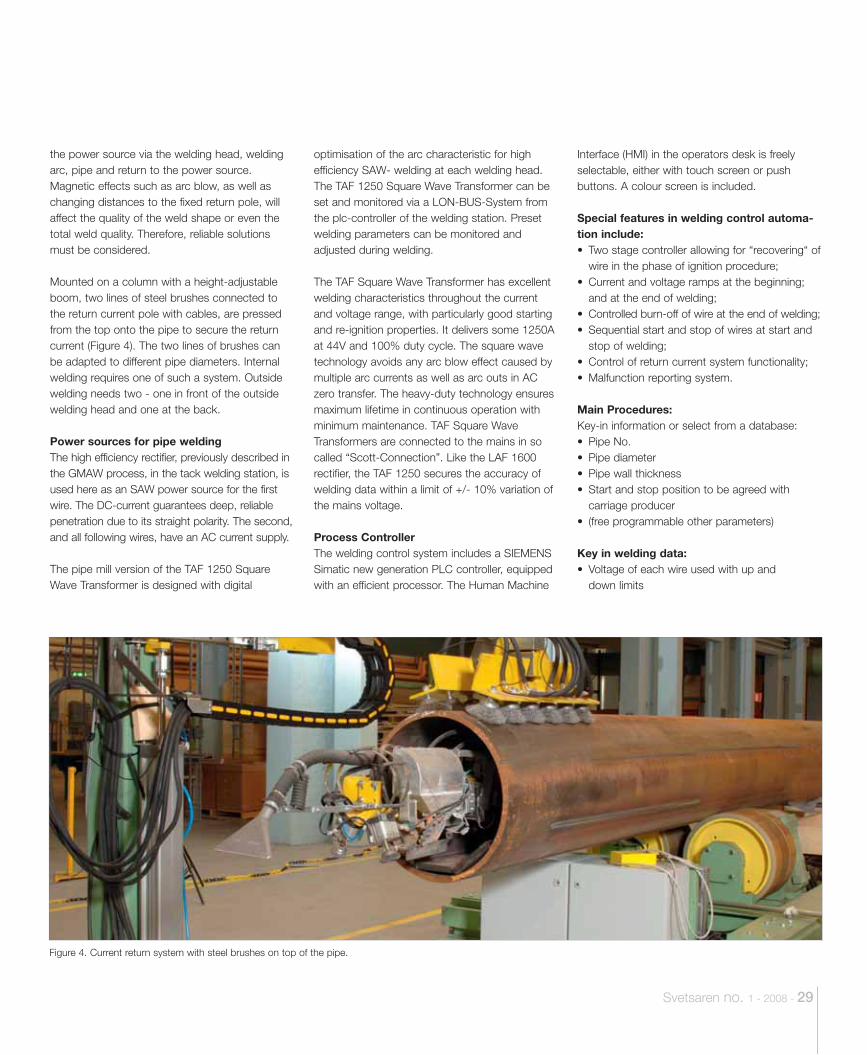
Internal boomThe internal boom has to fulfil many requirements. It needs to carry the welding head, including laser, video system, all current cables, flux support and suction hose, control cables and other parts. It requires the boom to be stable but, at the same time, as small as possible to also fit smaller pipes in 20” dimension. In the past, the maximum length was seldom more than 12m, plus run on and run off plates. Today, we sometimes need up to 18 or even 24m booms (spiral welding),
The demand for SAW-welded
pipes has grown steadily over
many years, with a significant
increase in both 2006 and 2007.
Worldwide, more than 150 pipe
mills produce an estimated
30,000,000 tonnes of SAW welded
pipes. When this production is split
between longitudinal and spiral
welded pipes, we see a ratio of
around 57/43%. ESAB is an estab-
lished, reliable partner in the pipe
mill segment, offering flux and wire
as well as equipment components
and controls.
EGBERT SCHOFER, ESAB AB, LAXÅ, SWEDEN AND MARTIN GEHRING, ESAB AB, GOTHENBURG SWEDEN.
A complete and reliable partner for pipe mills.
28 - Svetsaren no. 1 - 2008
The voltage pick-up brushes are quite important to get the right voltage signal back to the process controller, to fulfil the demands of the given WPS. This is believed to be a unique technique to correct the voltage losses over the long distance to the welding head. The stabilisation of the boom is a further effect to keep the weld pool stable.
Due to the high torque of ESAB’s VEC wire feeding motors, the decision was taken to position the wire feeding equipments at the end of the boom, while pushing the wire into the boom. This is different from most solutions in the market, but advanta-geous from a customers’ point of view. There is more space at the welding head for the positioning of the other components. and less weight at the welding head side. Wire straightness devices and wire feed motors are easily reachable and any service or exchange of feeding or guiding rolls is fast. There is also no temperature effect on the wire feeders and the inbuilt tachometer controls.
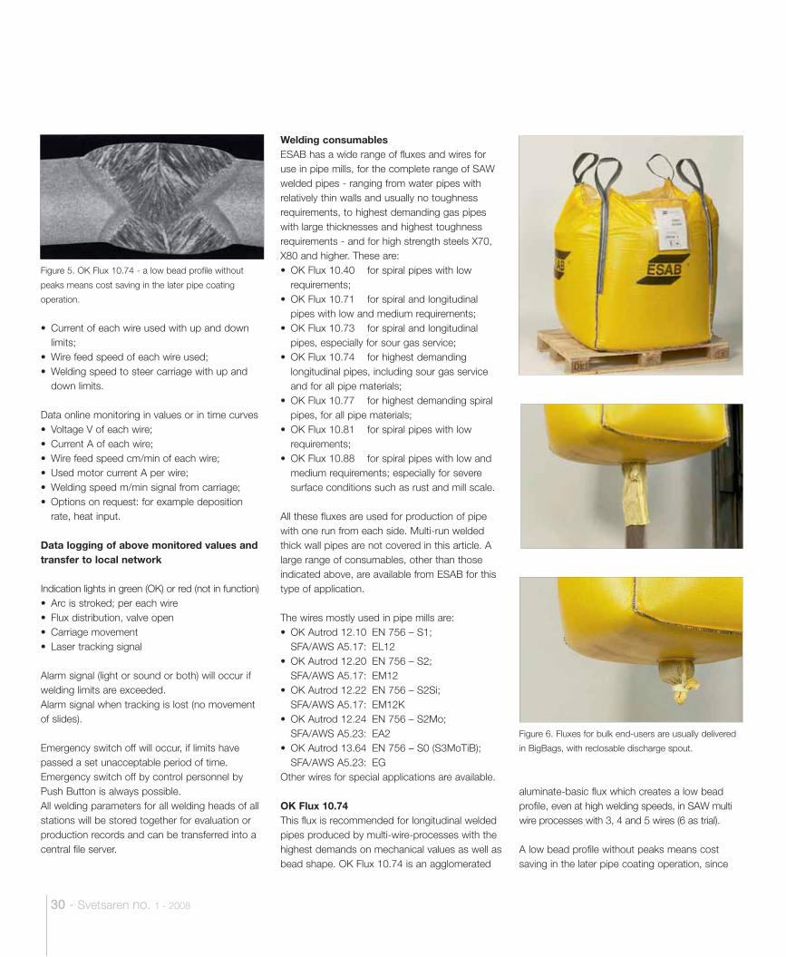
Internal welding headESAB has developed internal welding heads designed for up to 4 wires. As previously mentioned, many different components had to be integrated. The welding head itself is connected with the internal boom via a small cross slide, to always be guided in the middle of the weld preparation. A laser sensor controls the welding head via the cross slide. If a sideways movement outside the limit of the cross slide is necessary, a signal is transferred to the pipe carriage to turn the pipe accordingly. The welding process is supervised on an external monitor via a video camera. Also, the laser signal is distributed on the control panel. The wires are smoothly guided via wire liners into the contact equipment of the welding head (Figure 3). The contact equipment is built up with spring-loaded contact jaws and fixed spacers between the different wires. The spacers have a fixed angle, so that the wires have a defined fixed position for a given welding procedure. If a different set up of the wires is needed when changing pipe dimensions and accordingly the WPS, the spacers can be exchanged for a different set. This is normally not necessary.
Return Current SystemOne of the most important safeguards for a stable welding process is to secure the current flow from
Figure 1. GMAW tack welding head, including PEH
Control on swivelling arm and laser tracking system.
Figure 2. Internal boom (18m) with welding head for longitudinal pipe welding.
Figure 3. Internal longitudinal welding head (4 wires) in test phase, with 4 voltage pick up brushes with pneumatic cyl-
inders in front and behind the welding head.
without increasing the minimum pipe diameter to be welded. It is, therefore, not easy to fulfil a stable weld over a long distance.
ESAB`s solution is of a rigid, pre-stressed design to be linearly accurate over long distances (Figure 2). The rear part of the boom is a steel frame that is bolted to the concrete floor. The rear end of the boom has a pivot point in the frame and can be tilted by an hydraulic cylinder, to secure feeding-in of the pipes without danger of collision. For height positioning, the boom can be moved vertically to adapt to different pipe diameters, having in mind fixed carriages in height for the pipes. Four steel wire brushes press on the inside surface of the pipe for voltage pick-up and for stabilisation.
Svetsaren no. 1 - 2008 - 29
the power source via the welding head, welding arc, pipe and return to the power source. Magnetic effects such as arc blow, as well as changing distances to the fixed return pole, will affect the quality of the weld shape or even the total weld quality. Therefore, reliable solutions must be considered.
Mounted on a column with a height-adjustable boom, two lines of steel brushes connected to the return current pole with cables, are pressed from the top onto the pipe to secure the return current (Figure 4). The two lines of brushes can be adapted to different pipe diameters. Internal welding requires one of such a system. Outside welding needs two - one in front of the outside welding head and one at the back.
Power sources for pipe weldingThe high efficiency rectifier, previously described in the GMAW process, in the tack welding station, is used here as an SAW power source for the first wire. The DC-current guarantees deep, reliable penetration due to its straight polarity. The second, and all following wires, have an AC current supply.
The pipe mill version of the TAF 1250 Square Wave Transformer is designed with digital
optimisation of the arc characteristic for high efficiency SAW- welding at each welding head. The TAF 1250 Square Wave Transformer can be set and monitored via a LON-BUS-System from the plc-controller of the welding station. Preset welding parameters can be monitored and adjusted during welding.
The TAF Square Wave Transformer has excellent welding characteristics throughout the current and voltage range, with particularly good starting and re-ignition properties. It delivers some 1250A at 44V and 100% duty cycle. The square wave technology avoids any arc blow effect caused by multiple arc currents as well as arc outs in AC zero transfer. The heavy-duty technology ensures maximum lifetime in continuous operation with minimum maintenance. TAF Square Wave Transformers are connected to the mains in so called “Scott-Connection”. Like the LAF 1600 rectifier, the TAF 1250 secures the accuracy of welding data within a limit of +/- 10% variation of the mains voltage.
Process ControllerThe welding control system includes a SIEMENS Simatic new generation PLC controller, equipped with an efficient processor. The Human Machine
Interface (HMI) in the operators desk is freely selectable, either with touch screen or push buttons. A colour screen is included.
Special features in welding control automa-tion include:• Two stage controller allowing for “recovering“ of
wire in the phase of ignition procedure;• Current and voltage ramps at the beginning;
and at the end of welding;• Controlled burn-off of wire at the end of welding;• Sequential start and stop of wires at start and
stop of welding;• Control of return current system functionality;• Malfunction reporting system.
Main Procedures:Key-in information or select from a database:• Pipe No.• Pipe diameter• Pipe wall thickness• Start and stop position to be agreed with
carriage producer• (free programmable other parameters)
Key in welding data:• Voltage of each wire used with up and
down limits
Figure 4. Current return system with steel brushes on top of the pipe.
30 - Svetsaren no. 1 - 2008
• Current of each wire used with up and down limits;
• Wire feed speed of each wire used;• Welding speed to steer carriage with up and
down limits.
Data online monitoring in values or in time curves• Voltage V of each wire; • Current A of each wire; • Wire feed speed cm/min of each wire; • Used motor current A per wire;• Welding speed m/min signal from carriage;• Options on request: for example deposition
rate, heat input.
Data logging of above monitored values and transfer to local network
Indication lights in green (OK) or red (not in function)• Arc is stroked; per each wire• Flux distribution, valve open• Carriage movement• Laser tracking signal
Alarm signal (light or sound or both) will occur if welding limits are exceeded.Alarm signal when tracking is lost (no movement of slides).
Emergency switch off will occur, if limits have passed a set unacceptable period of time.Emergency switch off by control personnel by Push Button is always possible.All welding parameters for all welding heads of all stations will be stored together for evaluation or production records and can be transferred into a central file server.
Welding consumablesESAB has a wide range of fluxes and wires for use in pipe mills, for the complete range of SAW welded pipes - ranging from water pipes with relatively thin walls and usually no toughness requirements, to highest demanding gas pipes with large thicknesses and highest toughness requirements - and for high strength steels X70, X80 and higher. These are:• OK Flux 10.40 for spiral pipes with low
requirements;• OK Flux 10.71 for spiral and longitudinal
pipes with low and medium requirements;• OK Flux 10.73 for spiral and longitudinal
pipes, especially for sour gas service;• OK Flux 10.74 for highest demanding
longitudinal pipes, including sour gas service and for all pipe materials;
• OK Flux 10.77 for highest demanding spiral pipes, for all pipe materials;
• OK Flux 10.81 for spiral pipes with low requirements;
• OK Flux 10.88 for spiral pipes with low and medium requirements; especially for severe surface conditions such as rust and mill scale.
All these fluxes are used for production of pipe with one run from each side. Multi-run welded thick wall pipes are not covered in this article. A large range of consumables, other than those indicated above, are available from ESAB for this type of application.
The wires mostly used in pipe mills are:• OK Autrod 12.10 EN 756 – S1;
SFA/AWS A5.17: EL12• OK Autrod 12.20 EN 756 – S2;
SFA/AWS A5.17: EM12• OK Autrod 12.22 EN 756 – S2Si;
SFA/AWS A5.17: EM12K• OK Autrod 12.24 EN 756 – S2Mo;
SFA/AWS A5.23: EA2• OK Autrod 13.64 EN 756 – S0 (S3MoTiB);
SFA/AWS A5.23: EGOther wires for special applications are available.
OK Flux 10.74This flux is recommended for longitudinal welded pipes produced by multi-wire-processes with the highest demands on mechanical values as well as bead shape. OK Flux 10.74 is an agglomerated
aluminate-basic flux which creates a low bead profile, even at high welding speeds, in SAW multi wire processes with 3, 4 and 5 wires (6 as trial).
A low bead profile without peaks means cost saving in the later pipe coating operation, since
Figure 5. OK Flux 10.74 - a low bead profile without
peaks means cost saving in the later pipe coating
operation.
Figure 6. Fluxes for bulk end-users are usually delivered
in BigBags, with reclosable discharge spout.

Svetsaren no. 1 - 2008 - 31
ABOUT THE AUTHOR:
NAAM FUNCTIE.
secure highest toughness values. Pipe welding with 25.4mm thickness (1 inch) with one run from each side results in very high toughness values with OK Autrod 12.24. In this fabrication, 4 wires are used on the inside and 5 wires on the outside. All wires are 4.0mm diameter. The inside is welded with totally 50 kJ/cm and 170 cm/min. On the outside, 52 kJ/cm are used with a speed of 190 cm/min. The weld metal centre has over 115 J average at -20°C. At -30°C the average is about 100 J. Naturally, the weld bead shape fulfills all requirements as described above.
For some pipeline projects, good toughness values are required at temperatures below -20°C. Or the same requirements are valid for pipes with increased thickness. In these cases, the TiB alloyed solid wire OK Autrod 13.64 is used. The wire contains micro-elements which create a fine grained structure with a lot of acicular ferrite in the solidified weld metal. This results in toughness values which are even higher than those with OK Autrod 12.24.
Important for pipe mill welding is problem-free decoiling of a spool containing a sufficient amount of welding wire. For these applications, the ESAB EcoCoil is the answer (Figure 7). EcoCoil is a bulk spool containing 1000kg of welding wire. The packing material is reduced to a minimum, but still gives full protection for the wire against moisture and dust from inside and outside during transport and storage. All materials are fully recyclable. Since it is a one-way-package, there is no need for return logistics for empty spools. Advantages over high weight spools are achieved because a special technology ensures that the wire is not spooled tightly around the cardboard core. In the start and stop phase, the spool can slowly accelerate and slowly stop while welding wire is fed with constant speed to the welding head. Welding defects are thus reduced.
The customer and the customer´s challenge are ESAB’s main focus. The products and packages described in this article have been developed in close cooperation with customers and, as a result, OK Flux 10.74 in BigBag, OK Autrod 12.24 and OK Autrod 13.64 on EcoCoil are commonly found in longitudinal pipe mills.
the coating thickness can be reduced (Figure 5). Moreover, the API specifications for line pipes, and many customer specifications, require a maximum reinforcement of 3.0mm. However, a reinforcement of 0.5 to 2.5mm is desired. The transition angle from weld metal to base material needs to be smooth in order to avoid mechanical notches. All these requirements are fulfilled with OK Flux 10.74 provided the parameters are set properly. The flux works equally well on DC and AC current. Usually the first wire is welded with DC+ current and all the remaining wires with AC. This is in order to reduce magnetic interference between the wires. OK Flux 10.74 is suitable for different wires for all pipe materials. The flux is hydrogen controlled which is important for high strength materials such as X80 and X100. OK Flux 10.74 alloys some Si and Mn to the weld metal for the highest toughness levels. Careful metallurgical design ensures that it produces a weld metal without any macro or micro areas with increased hardness.Customers around the globe appreciate OK Flux 10.74 for its excellent weldability, weld bead pro-file and secure toughness values. BigBagsFluxes for bulk end-users are usually delivered in BigBags (Figure 6). Standard weight for BigBags is 1000kg. BigBags have a well defined, reclosable discharge spout. Since it takes about 25 seconds on “full open” to empty a complete 1000kg BigBag, customers can easily remove just a few kg at a time. Thus, all kinds of flux supply units can be filled with flux from BigBags. The enclosed BigBags are made of woven polypropylene material which has an internal moisture protection coating to keep the contents dry. The material is fully recyclable. Each palette of flux is additionally protected against moisture by wrap foil or shrink foil.
Wire and wire packageFor high demanding pipes, OK Autrod 12.24 (EN 756 - S2Mo; AWS EA2) is widely used. For this wire , the chemical elements are specified with more restricted limits than those in both of the standards with which the wire complies. Additionally, impurities are named and limited to a maximum level (which is in the range of a couple hundredths of a percent). This is in order to
Figure 7. EcoCoil - problem-free decoiling of a spool
containing a bulk amount of welding wire for pipe mills.
ABOUT THE AUTHORS:
EGBERT SCHOFER IS AUTOMATION TECHNOLOGY MANAGER AT ESAB AB, LAXÅ, SWEDEN.
MARTIN GEHRING IS GROUP PRODUCT MANAGER NON- AND LOW-ALLOYED SAW FLUXES AND WIRES AT ESAB, GOTHENBURG, SWEDEN.
.

32 - Svetsaren no. 1 - 2008
An integrated petrochemical plant
for hydrocarbons processing in
Al-Shuaiba, Kuwait, is being
expanded by the addition of
numerous tanks with varying
purposes. The Italian construction
company Paresa SpA was
responsible for the on-site erection
of two spherical tanks. One, of
7200 m3 capacity, in carbon steel,
is for the storage of polypropylene.
The other, of 5500 m3 capacity, in
stainless steel, is for the storage of
polyethylene. Polypropylene and
polyethylene are raw materials for
the production of plastics.
Paresa SpA, Cesana, Italy, is an international building company specialising in the on-site construction of underground storage tanks, tanks for cryogenic liquids and cylindrical and spherical pressurised tanks for the petrochemical industry. Paresa is renowned for its highly experienced personnel, research and training and quality and safety programmes. Accreditations include ISO 9001 quality management certification, ISO 14001 environmental management certification, and prestigious ASME authorisation for the use of U and U2 symbol stamps in accordance with the ASME Boiler and Pressure Vessel Code - particularly important for the project in Kuwait. The spheresThe spherical shape represents the optimal ratio between volume and surface. A natural phenome-
non, this characteristic is very popular in engineering. However, copying the quality and perfection of nature in a man-made construction is not easy, as explained by Paresa’s Technical Supervisor, Raffaele Cedioli and Quality Control Manager, Nicolò Amodio.
“The carbon steel tank is 24m in diameter with a wall thickness of 34-38mm. The stainless steel tank is 22m in diameter with a wall thickness of 30mm. The latter is particularly interesting as, to our knowledge, it is one of the largest ever constructed in this material. It needs a series of complicated and closely coordinated operations to be able to meet the final building and quality requirements.”
“The choice of stainless steel”, says Mr. Cedioli, “is not primarily governed by the aggressiveness
BRUNO MALAGOLI, ESAB SPA., MESERO, ITALY.
Paresa SpA construct spheres for the Kuwait petrochemical industry
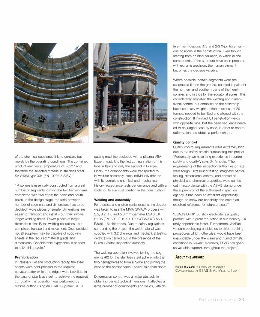
Svetsaren no. 1 - 2008 - 33
of the chemical substance it is to contain, but merely by the operating conditions. The contained product reaches a temperature of -89°C and therefore the selected material is stainless steel SA 240M type 304 (EN 10204 3.2/BV).”
“ A sphere is essentially constructed from a great number of segments forming the two hemispheres, completed with two caps; the north and south poles. In the design stage, the ratio between number of segments and dimensions has to be decided. More pieces of smaller dimensions are easier to transport and install - but they involve longer welding times. Fewer pieces of larger dimensions simplify the welding operations - but complicate transport and movement. Once decided, not all suppliers may be capable of supplying sheets in the required material grade and dimensions. Considerable experience is needed to solve this puzzle.”
PrefabricationIn Paresa’s Cesana production facility, the steel sheets were cold-pressed to the required curvature after which the edges were bevelled. In the case of stainless steel, to achieve the required cut quality, this operation was performed by plasma cutting using an ESAB Suprarex SXE-P
cutting machine equipped with a plasma VBA-Expert head. It is the first cutting station of this type in Italy and only the second in Europe. Finally, the components were transported to Kuwait for assembly, each individually marked with its complete chemical and mechanical history, acceptance tests performance and with a code for its eventual position in the construction.
Welding and assemblyFor practical and environmental reasons, the decision was taken to use the MMA (SMAW) process with 2.5, 3.2, 4.0 and 5.0 mm diameter ESAB OK 61.35 (EN1600: E 19 9 L B 22/SFA/AWS A5.4: E308L-15) electrodes. Due to safety regulations surrounding the project, the weld material was supplied with 3.2 chemical and mechanical testing certification carried out in the presence of the Bureau Veritas inspection authority.
The welding operation involves joining the seg-ments (62 for the stainless steel sphere) into the two hemispheres to form a globe and joining the caps to the hemispheres - easier said than done!
Deformation control was a major obstacle in obtaining perfect globe dimensions. It affected a large number of components and welds, with dif-
ferent joint designs (1/3 and 2/3 X-joints) at vari-ous positions in the construction. Even though starting from an ideal situation, in which all the components of the structure have been prepared with extreme precision, the human element becomes the decisive variable.
Where possible, certain segments were pre-assembled flat on the ground, coupled in pairs for the northern and southern parts of the hemi-spheres and in trios for the equatorial zones. This considerably simplified the welding and dimen-sional control, but complicated the assembly, because heavy weights, often in excess of 20 tonnes, needed to be lifted and aligned with the construction. It involved full penetration welds with opposite runs, but the bead sequence need-ed to be judged case by case, in order to control deformation and obtain a perfect shape.
Quality controlQuality control requirements were extremely high, due to the safety criteria surrounding this project. “Fortunately we have long experience in control, safety and quality”, says Dr. Amodio. “The requirements of the inspection authorities on site were tough. Ultrasound testing, magnetic partical testing, dimensional control, and control of physical and chemical properties, were carried out in accordance with the ASME stamp under the supervision of the authorised inspection agency. It has been an excellent opportunity, though, to show our capability and create an excellent reference for future projects”.
“ESAB’s OK 61.35 stick electrode is a quality product with a great reputation in our industry – a really dependable factor. Furthermore, VacPac vacuum packaging enables us to skip re-baking procedures which, otherwise, would have been unavoidable under the warm and humid climatic conditions in Kuwait. Moreover, ESAB has given us valuable support, throughout the project”.
ABOUT THE AUTHOR:
BRUNO MALAGOLI IS PRODUCT MANAGER CONSUMABLES AT ESAB SPA., MESERO, ITALY.
34 - Svetsaren no. 1 - 2008
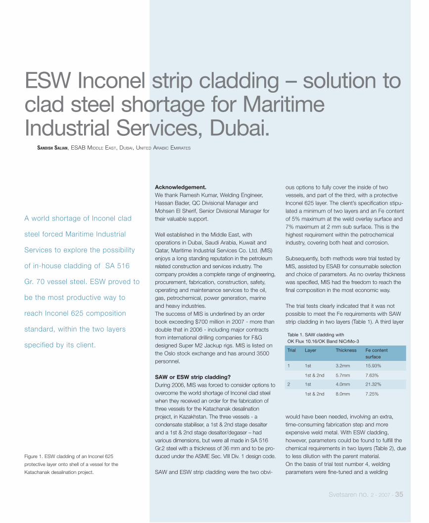
Figure 1. ESW cladding of an Inconel 625
protective layer onto shell of a vessel for the
Katachanak desalination project.
Svetsaren no. 2 - 2007 - 35
Acknowledgement.We thank Ramesh Kumar, Welding Engineer, Hassan Bader, QC Divisional Manager and Mohsen El Sherif, Senior Divisional Manager for their valuable support.
Well established in the Middle East, with operations in Dubai, Saudi Arabia, Kuwait and Qatar, Maritime Industrial Services Co. Ltd. (MIS) enjoys a long standing reputation in the petroleum related construction and services industry. The company provides a complete range of engineering, procurement, fabrication, construction, safety, operating and maintenance services to the oil, gas, petrochemical, power generation, marine and heavy industries. The success of MIS is underlined by an order book exceeding $700 million in 2007 - more than double that in 2006 - including major contracts from international drilling companies for F&G designed Super M2 Jackup rigs. MIS is listed on the Oslo stock exchange and has around 3500 personnel.
SAW or ESW strip cladding?During 2006, MIS was forced to consider options to overcome the world shortage of Inconel clad steel when they received an order for the fabrication of three vessels for the Katachanak desalination project, in Kazakhstan. The three vessels - a condensate stabiliser, a 1st & 2nd stage desalter and a 1st & 2nd stage desalter/degaser – had various dimensions, but were all made in SA 516 Gr.2 steel with a thickness of 36 mm and to be pro-duced under the ASME Sec. VIII Div. 1 design code.
SAW and ESW strip cladding were the two obvi-
ous options to fully cover the inside of two vessels, and part of the third, with a protective Inconel 625 layer. The client’s specification stipu-lated a minimum of two layers and an Fe content of 5% maximum at the weld overlay surface and 7% maximum at 2 mm sub surface. This is the highest requirement within the petrochemical industry, covering both heat and corrosion.
Subsequently, both methods were trial tested by MIS, assisted by ESAB for consumable selection and choice of parameters. As no overlay thickness was specified, MIS had the freedom to reach the final composition in the most economic way.
The trial tests clearly indicated that it was not possible to meet the Fe requirements with SAW strip cladding in two layers (Table 1). A third layer
A world shortage of Inconel clad
steel forced Maritime Industrial
Services to explore the possibility
of in-house cladding of SA 516
Gr. 70 vessel steel. ESW proved to
be the most productive way to
reach Inconel 625 composition
standard, within the two layers
specified by its client.
SANDISH SALIAN, ESAB MIDDLE EAST, DUBAI, UNITED ARABIC EMIRATES
ESW Inconel strip cladding – solution to clad steel shortage for Maritime Industrial Services, Dubai.
Table 1. SAW cladding with OK Flux 10.16/OK Band NiCrMo-3
Trial Layer Thickness Fe content surface
1 1st 3.2mm 15.93%
1st & 2nd 5.7mm 7.63%
2 1st 4.0mm 21.32%
1st & 2nd 8.0mm 7.25%
would have been needed, involving an extra, time-consuming fabrication step and more expensive weld metal. With ESW cladding, however, parameters could be found to fulfill the chemical requirements in two layers (Table 2), due to less dilution with the parent material. On the basis of trial test number 4, welding parameters were fine-tuned and a welding
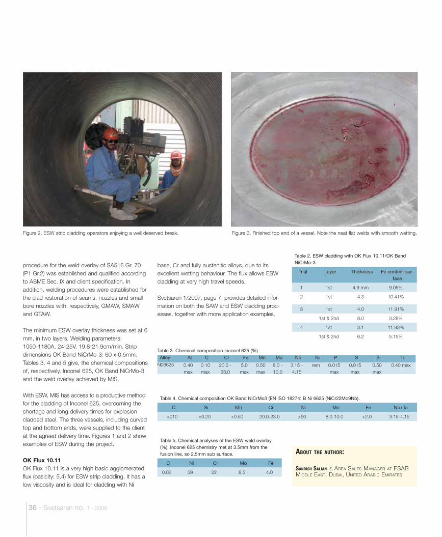
36 - Svetsaren no. 1 - 2008
ABOUT THE AUTHOR:
SANDISH SALIAN IS AREA SALES MANAGER AT ESAB MIDDLE EAST, DUBAI, UNITED ARABIC EMIRATES.
base, Cr and fully austenitic alloys, due to its excellent wetting behaviour. The flux allows ESW cladding at very high travel speeds.
Svetsaren 1/2007, page 7, provides detailed infor-mation on both the SAW and ESW cladding proc-esses, together with more application examples.
Table 2. ESW cladding with OK Flux 10.11/OK Band NiCrMo-3
Trial Layer Thickness Fe content sur-face
1 1st 4.9 mm 9.05%
2 1st 4.3 10.41%
3 1st 4.0 11.91%
1st & 2nd 8.0 3.28%
4 1st 3.1 11.93%
1st & 2nd 6.2 5.15%
Table 4. Chemical composition OK Band NiCrMo3 (EN ISO 18274: B Ni 6625 (NiCr22Mo9Nb).
C Si Mn Cr Ni Mo Fe Nb+Ta
<010 <0.20 <0.50 20.0-23.0 >60 8.0-10.0 <2.0 3.15-4.15
Table 5. Chemical analyses of the ESW weld overlay (%). Inconel 625 chemistry met at 3.5mm from the fusion line, so 2.5mm sub surface.
C Ni Cr Mo Fe
0.02 59 22 8.5 4.0
Table 3. Chemical composition Inconel 625 (%)
Alloy Al C Cr Fe Mn Mo Nb Ni P S Si Ti
N06625 0.40 max
0.10 max
20.0 - 23.0
5.0 max
0.50 max
8.0 - 10.0
3.15 - 4.15
rem 0.015 max
0.015 max
0.50 max
0.40 max
Figure 3. Finished top end of a vessel. Note the neat flat welds with smooth wetting.
procedure for the weld overlay of SA516 Gr. 70 (P1 Gr.2) was established and qualified according to ASME Sec. IX and client specification. In addition, welding procedures were established for the clad restoration of seams, nozzles and small bore nozzles with, respectively, GMAW, SMAW and GTAW.
The minimum ESW overlay thickness was set at 6 mm, in two layers. Welding parameters: 1050-1180A, 24-25V, 19.8-21.9cm/min. Strip dimensions OK Band NiCrMo-3: 60 x 0.5mm. Tables 3, 4 and 5 give, the chemical compositions of, respectively, Inconel 625, OK Band NiCrMo-3 and the weld overlay achieved by MIS.
With ESW, MIS has access to a productive method for the cladding of Inconel 625, overcoming the shortage and long delivery times for explosion cladded steel. The three vessels, including curved top and bottom ends, were supplied to the client at the agreed delivery time. Figures 1 and 2 show examples of ESW during the project.
OK Flux 10.11OK Flux 10.11 is a very high basic agglomerated flux (basicity: 5.4) for ESW strip cladding. It has a low viscosity and is ideal for cladding with Ni
Figure 2. ESW strip cladding operators enjoying a well deserved break.
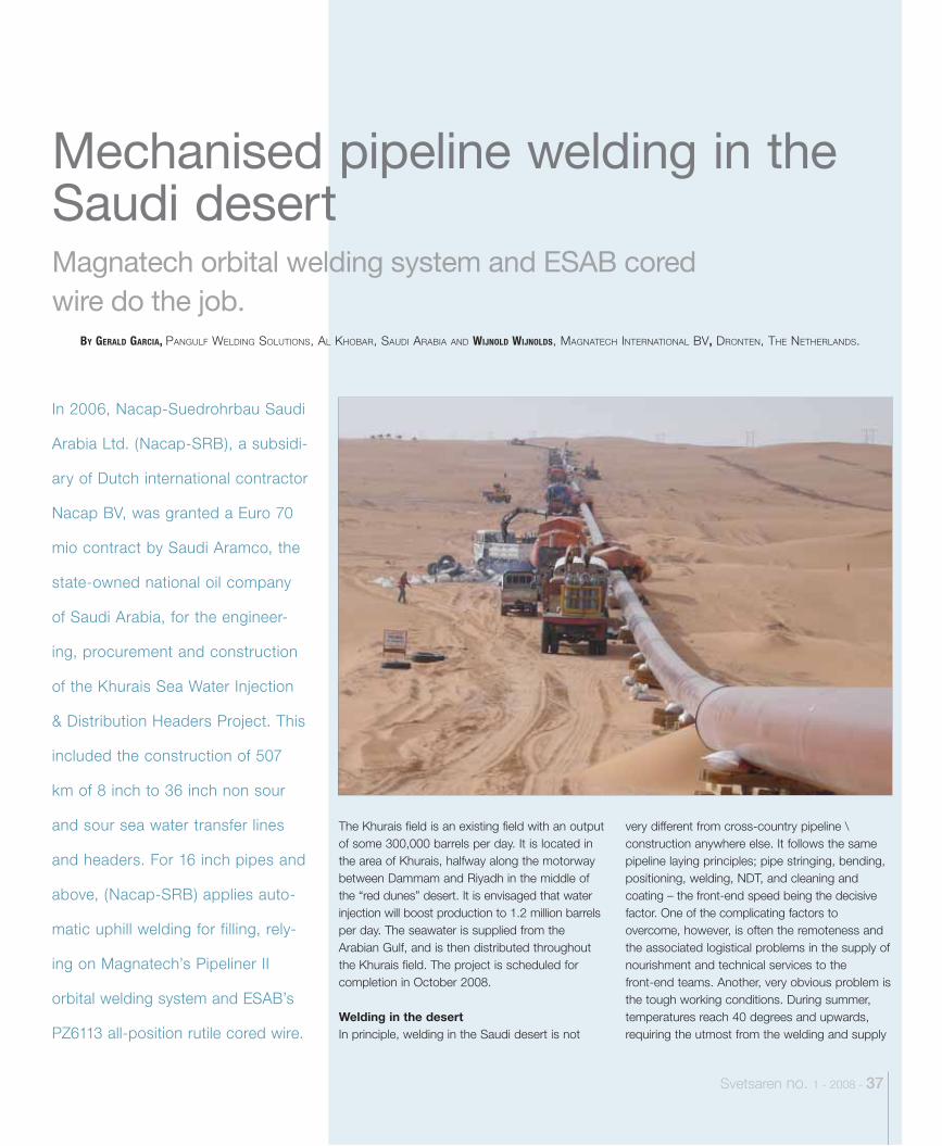
Magnatech orbital welding system and ESAB cored wire do the job.
Svetsaren no. 1 - 2008 - 37
In 2006, Nacap-Suedrohrbau Saudi
Arabia Ltd. (Nacap-SRB), a subsidi-
ary of Dutch international contractor
Nacap BV, was granted a Euro 70
mio contract by Saudi Aramco, the
state-owned national oil company
of Saudi Arabia, for the engineer-
ing, procurement and construction
of the Khurais Sea Water Injection
& Distribution Headers Project. This
included the construction of 507
km of 8 inch to 36 inch non sour
and sour sea water transfer lines
and headers. For 16 inch pipes and
above, (Nacap-SRB) applies auto-
matic uphill welding for filling, rely-
ing on Magnatech’s Pipeliner II
orbital welding system and ESAB’s
PZ6113 all-position rutile cored wire.
The Khurais field is an existing field with an output of some 300,000 barrels per day. It is located in the area of Khurais, halfway along the motorway between Dammam and Riyadh in the middle of the “red dunes” desert. It is envisaged that water injection will boost production to 1.2 million barrels per day. The seawater is supplied from the Arabian Gulf, and is then distributed throughout the Khurais field. The project is scheduled for completion in October 2008.
Welding in the desertIn principle, welding in the Saudi desert is not
very different from cross-country pipeline \construction anywhere else. It follows the same pipeline laying principles; pipe stringing, bending, positioning, welding, NDT, and cleaning and coating – the front-end speed being the decisive factor. One of the complicating factors to overcome, however, is often the remoteness and the associated logistical problems in the supply of nourishment and technical services to the front-end teams. Another, very obvious problem is the tough working conditions. During summer, temperatures reach 40 degrees and upwards, requiring the utmost from the welding and supply
BY GERALD GARCIA, PANGULF WELDING SOLUTIONS, AL KHOBAR, SAUDI ARABIA AND WIJNOLD WIJNOLDS, MAGNATECH INTERNATIONAL BV, DRONTEN, THE NETHERLANDS.
Mechanised pipeline welding in the Saudi desert
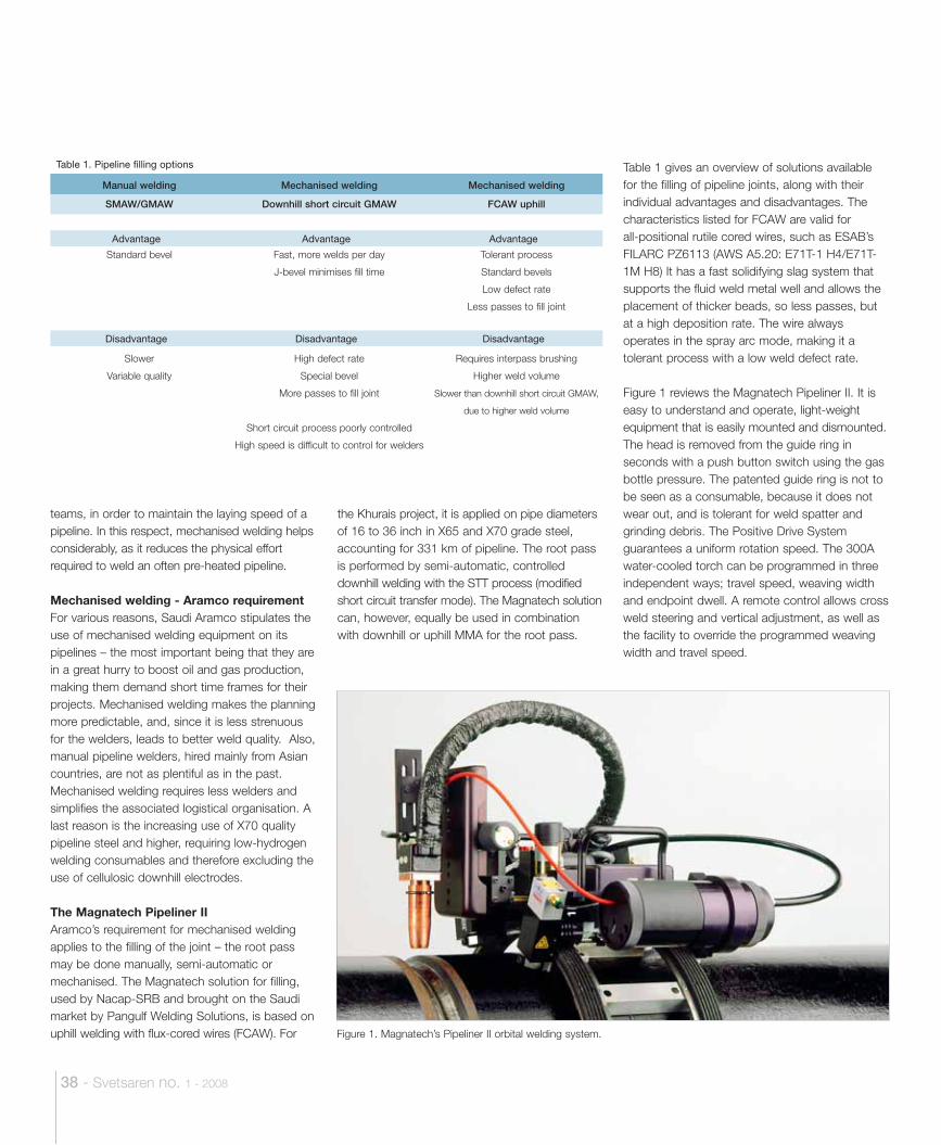
38 - Svetsaren no. 1 - 2008
teams, in order to maintain the laying speed of a pipeline. In this respect, mechanised welding helps considerably, as it reduces the physical effort required to weld an often pre-heated pipeline.
Mechanised welding - Aramco requirement For various reasons, Saudi Aramco stipulates the use of mechanised welding equipment on its pipelines – the most important being that they are in a great hurry to boost oil and gas production, making them demand short time frames for their projects. Mechanised welding makes the planning more predictable, and, since it is less strenuous for the welders, leads to better weld quality. Also, manual pipeline welders, hired mainly from Asian countries, are not as plentiful as in the past. Mechanised welding requires less welders and simplifies the associated logistical organisation. A last reason is the increasing use of X70 quality pipeline steel and higher, requiring low-hydrogen welding consumables and therefore excluding the use of cellulosic downhill electrodes.
The Magnatech Pipeliner IIAramco’s requirement for mechanised welding applies to the filling of the joint – the root pass may be done manually, semi-automatic or mechanised. The Magnatech solution for filling, used by Nacap-SRB and brought on the Saudi market by Pangulf Welding Solutions, is based on uphill welding with flux-cored wires (FCAW). For
the Khurais project, it is applied on pipe diameters of 16 to 36 inch in X65 and X70 grade steel, accounting for 331 km of pipeline. The root pass is performed by semi-automatic, controlled downhill welding with the STT process (modified short circuit transfer mode). The Magnatech solution can, however, equally be used in combination with downhill or uphill MMA for the root pass.
Table 1 gives an overview of solutions available for the filling of pipeline joints, along with their individual advantages and disadvantages. The characteristics listed for FCAW are valid for all-positional rutile cored wires, such as ESAB’s FILARC PZ6113 (AWS A5.20: E71T-1 H4/E71T-1M H8) It has a fast solidifying slag system that supports the fluid weld metal well and allows the placement of thicker beads, so less passes, but at a high deposition rate. The wire always operates in the spray arc mode, making it a tolerant process with a low weld defect rate.
Figure 1 reviews the Magnatech Pipeliner II. It is easy to understand and operate, light-weight equipment that is easily mounted and dismounted. The head is removed from the guide ring in seconds with a push button switch using the gas bottle pressure. The patented guide ring is not to be seen as a consumable, because it does not wear out, and is tolerant for weld spatter and grinding debris. The Positive Drive System guarantees a uniform rotation speed. The 300A water-cooled torch can be programmed in three independent ways; travel speed, weaving width and endpoint dwell. A remote control allows cross weld steering and vertical adjustment, as well as the facility to override the programmed weaving width and travel speed.
Table 1. Pipeline filling options
Manual welding Mechanised welding Mechanised welding
SMAW/GMAW Downhill short circuit GMAW FCAW uphill
Advantage Advantage Advantage
Standard bevel Fast, more welds per day Tolerant process
J-bevel minimises fill time Standard bevels
Low defect rate
Less passes to fill joint
Disadvantage Disadvantage Disadvantage
Slower High defect rate Requires interpass brushing
Variable quality Special bevel Higher weld volume
More passes to fill joint Slower than downhill short circuit GMAW,
due to higher weld volume
Short circuit process poorly controlled
High speed is difficult to control for welders
Figure 1. Magnatech’s Pipeliner II orbital welding system.
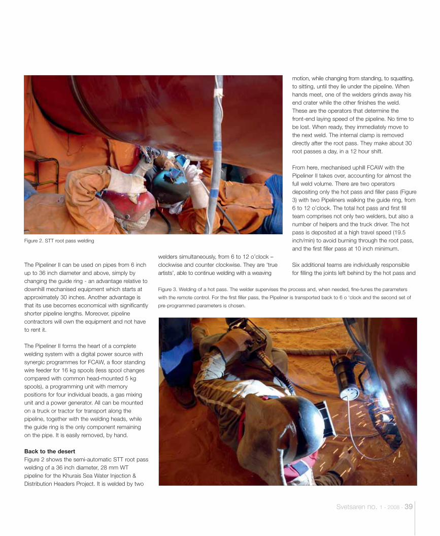
Svetsaren no. 1 - 2008 - 39
welders simultaneously, from 6 to 12 o’clock – clockwise and counter clockwise. They are ‘true artists’, able to continue welding with a weaving
motion, while changing from standing, to squatting, to sitting, until they lie under the pipeline. When hands meet, one of the welders grinds away his end crater while the other finishes the weld. These are the operators that determine the front-end laying speed of the pipeline. No time to be lost. When ready, they immediately move to the next weld. The internal clamp is removed directly after the root pass. They make about 30 root passes a day, in a 12 hour shift.
From here, mechanised uphill FCAW with the Pipeliner II takes over, accounting for almost the full weld volume. There are two operators depositing only the hot pass and filler pass (Figure 3) with two Pipeliners walking the guide ring, from 6 to 12 o’clock. The total hot pass and first fill team comprises not only two welders, but also a number of helpers and the truck driver. The hot pass is deposited at a high travel speed (19.5 inch/min) to avoid burning through the root pass, and the first filler pass at 10 inch minimum.
Six additional teams are individually responsible for filling the joints left behind by the hot pass and
The Pipeliner II can be used on pipes from 6 inch up to 36 inch diameter and above, simply by changing the guide ring - an advantage relative to downhill mechanised equipment which starts at approximately 30 inches. Another advantage is that its use becomes economical with significantly shorter pipeline lengths. Moreover, pipeline contractors will own the equipment and not have to rent it.
The Pipeliner II forms the heart of a complete welding system with a digital power source with synergic programmes for FCAW, a floor standing wire feeder for 16 kg spools (less spool changes compared with common head-mounted 5 kg spools), a programming unit with memory positions for four individual beads, a gas mixing unit and a power generator. All can be mounted on a truck or tractor for transport along the pipeline, together with the welding heads, while the guide ring is the only component remaining on the pipe. It is easily removed, by hand.
Back to the desertFigure 2 shows the semi-automatic STT root pass welding of a 36 inch diameter, 28 mm WT pipeline for the Khurais Sea Water Injection & Distribution Headers Project. It is welded by two
Figure 2. STT root pass welding
Figure 3. Welding of a hot pass. The welder supervises the process and, when needed, fine-tunes the parameters
with the remote control. For the first filler pass, the Pipeliner is transported back to 6 o ‘clock and the second set of
pre-programmed parameters is chosen.
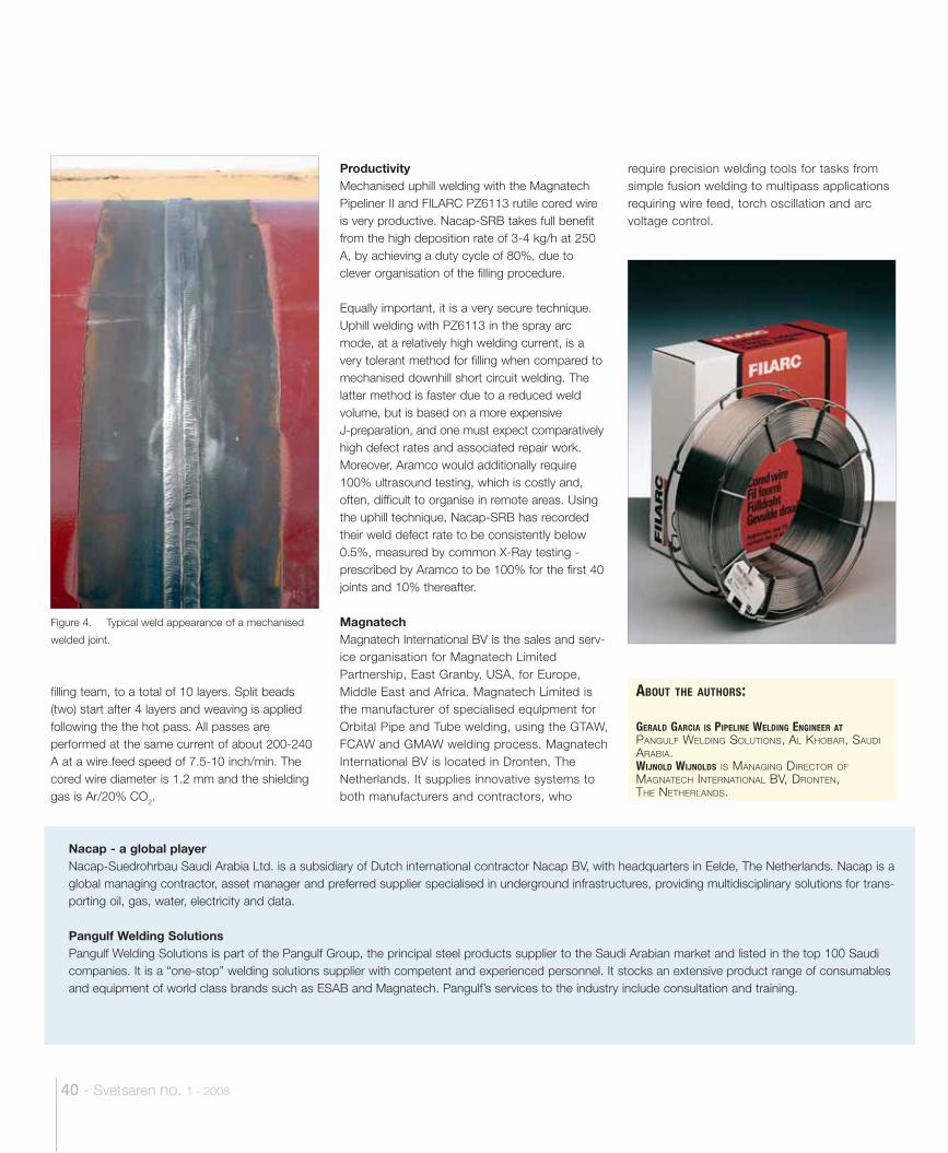
40 - Svetsaren no. 1 - 2008
filling team, to a total of 10 layers. Split beads (two) start after 4 layers and weaving is applied following the the hot pass. All passes are performed at the same current of about 200-240 A at a wire feed speed of 7.5-10 inch/min. The cored wire diameter is 1.2 mm and the shielding gas is Ar/20% CO2.
ProductivityMechanised uphill welding with the Magnatech Pipeliner II and FILARC PZ6113 rutile cored wire is very productive. Nacap-SRB takes full benefit from the high deposition rate of 3-4 kg/h at 250 A, by achieving a duty cycle of 80%, due to clever organisation of the filling procedure.
Equally important, it is a very secure technique. Uphill welding with PZ6113 in the spray arc mode, at a relatively high welding current, is a very tolerant method for filling when compared to mechanised downhill short circuit welding. The latter method is faster due to a reduced weld volume, but is based on a more expensive J-preparation, and one must expect comparatively high defect rates and associated repair work. Moreover, Aramco would additionally require 100% ultrasound testing, which is costly and, often, difficult to organise in remote areas. Using the uphill technique, Nacap-SRB has recorded their weld defect rate to be consistently below 0.5%, measured by common X-Ray testing - prescribed by Aramco to be 100% for the first 40 joints and 10% thereafter.
MagnatechMagnatech International BV is the sales and serv-ice organisation for Magnatech Limited Partnership, East Granby, USA, for Europe, Middle East and Africa. Magnatech Limited is the manufacturer of specialised equipment for Orbital Pipe and Tube welding, using the GTAW, FCAW and GMAW welding process. Magnatech International BV is located in Dronten, The Netherlands. It supplies innovative systems to both manufacturers and contractors, who
require precision welding tools for tasks from simple fusion welding to multipass applications requiring wire feed, torch oscillation and arc voltage control.
Nacap - a global playerNacap-Suedrohrbau Saudi Arabia Ltd. is a subsidiary of Dutch international contractor Nacap BV, with headquarters in Eelde, The Netherlands. Nacap is a global managing contractor, asset manager and preferred supplier specialised in underground infrastructures, providing multidisciplinary solutions for trans-porting oil, gas, water, electricity and data.
Pangulf Welding SolutionsPangulf Welding Solutions is part of the Pangulf Group, the principal steel products supplier to the Saudi Arabian market and listed in the top 100 Saudi companies. It is a “one-stop” welding solutions supplier with competent and experienced personnel. It stocks an extensive product range of consumables and equipment of world class brands such as ESAB and Magnatech. Pangulf’s services to the industry include consultation and training.
Figure 4. Typical weld appearance of a mechanised
welded joint.
ABOUT THE AUTHORS:
GERALD GARCIA IS PIPELINE WELDING ENGINEER AT PANGULF WELDING SOLUTIONS, AL KHOBAR, SAUDI ARABIA.WIJNOLD WIJNOLDS IS MANAGING DIRECTOR OF MAGNATECH INTERNATIONAL BV, DRONTEN, THE NETHERLANDS.
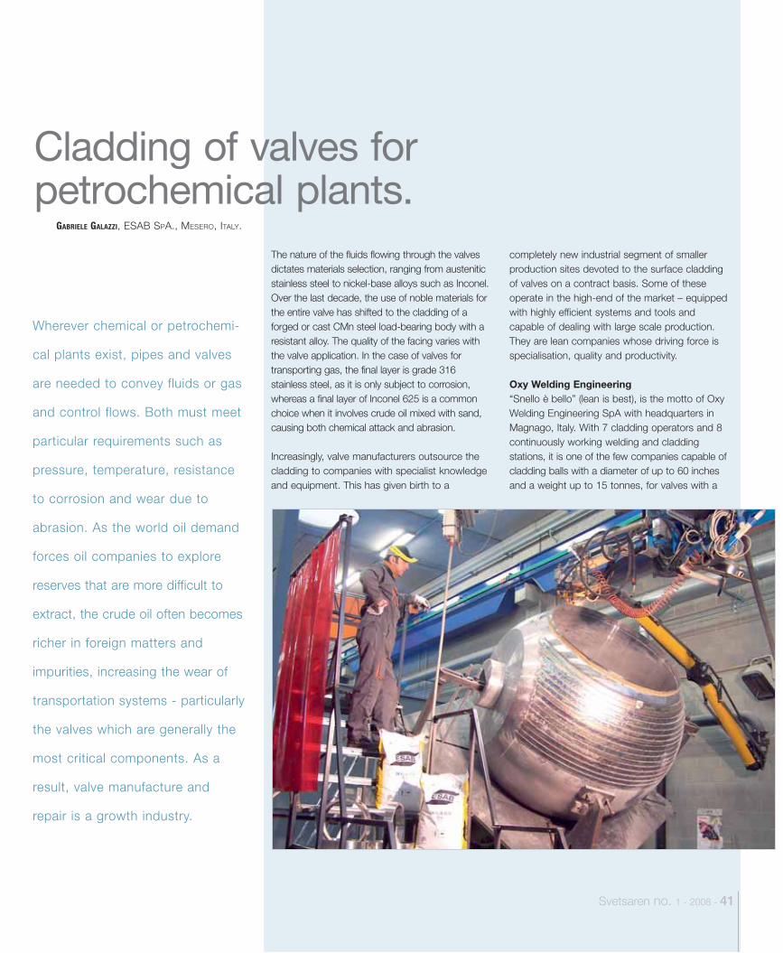
Svetsaren no. 1 - 2008 - 41
Wherever chemical or petrochemi-
cal plants exist, pipes and valves
are needed to convey fluids or gas
and control flows. Both must meet
particular requirements such as
pressure, temperature, resistance
to corrosion and wear due to
abrasion. As the world oil demand
forces oil companies to explore
reserves that are more difficult to
extract, the crude oil often becomes
richer in foreign matters and
impurities, increasing the wear of
transportation systems - particularly
the valves which are generally the
most critical components. As a
result, valve manufacture and
repair is a growth industry.
GABRIELE GALAZZI, ESAB SPA., MESERO, ITALY.
Cladding of valves for petrochemical plants.
The nature of the fluids flowing through the valves dictates materials selection, ranging from austenitic stainless steel to nickel-base alloys such as Inconel. Over the last decade, the use of noble materials for the entire valve has shifted to the cladding of a forged or cast CMn steel load-bearing body with a resistant alloy. The quality of the facing varies with the valve application. In the case of valves for transporting gas, the final layer is grade 316 stainless steel, as it is only subject to corrosion, whereas a final layer of Inconel 625 is a common choice when it involves crude oil mixed with sand, causing both chemical attack and abrasion.
Increasingly, valve manufacturers outsource the cladding to companies with specialist knowledge and equipment. This has given birth to a
completely new industrial segment of smaller production sites devoted to the surface cladding of valves on a contract basis. Some of these operate in the high-end of the market – equipped with highly efficient systems and tools and capable of dealing with large scale production. They are lean companies whose driving force is specialisation, quality and productivity.
Oxy Welding Engineering“Snello è bello” (lean is best), is the motto of Oxy Welding Engineering SpA with headquarters in Magnago, Italy. With 7 cladding operators and 8 continuously working welding and cladding stations, it is one of the few companies capable of cladding balls with a diameter of up to 60 inches and a weight up to 15 tonnes, for valves with a
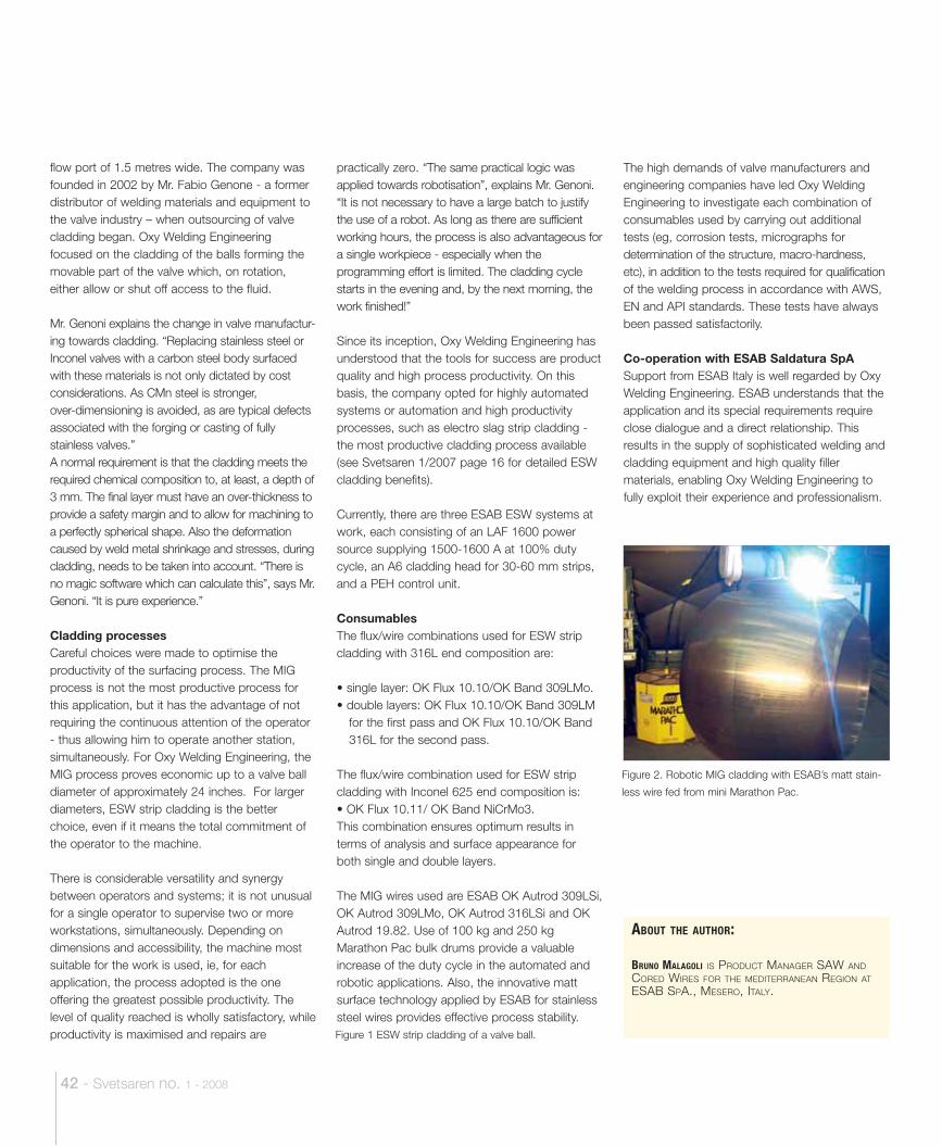
42 - Svetsaren no. 1 - 2008
Figure 1 ESW strip cladding of a valve ball.
flow port of 1.5 metres wide. The company was founded in 2002 by Mr. Fabio Genone - a former distributor of welding materials and equipment to the valve industry – when outsourcing of valve cladding began. Oxy Welding Engineering focused on the cladding of the balls forming the movable part of the valve which, on rotation, either allow or shut off access to the fluid.
Mr. Genoni explains the change in valve manufactur-ing towards cladding. “Replacing stainless steel or Inconel valves with a carbon steel body surfaced with these materials is not only dictated by cost considerations. As CMn steel is stronger, over-dimensioning is avoided, as are typical defects associated with the forging or casting of fully stainless valves.” A normal requirement is that the cladding meets the required chemical composition to, at least, a depth of 3 mm. The final layer must have an over-thickness to provide a safety margin and to allow for machining to a perfectly spherical shape. Also the deformation caused by weld metal shrinkage and stresses, during cladding, needs to be taken into account. “There is no magic software which can calculate this”, says Mr. Genoni. “It is pure experience.”
Cladding processesCareful choices were made to optimise the productivity of the surfacing process. The MIG process is not the most productive process for this application, but it has the advantage of not requiring the continuous attention of the operator - thus allowing him to operate another station, simultaneously. For Oxy Welding Engineering, the MIG process proves economic up to a valve ball diameter of approximately 24 inches. For larger diameters, ESW strip cladding is the better choice, even if it means the total commitment of the operator to the machine.
There is considerable versatility and synergy between operators and systems; it is not unusual for a single operator to supervise two or more workstations, simultaneously. Depending on dimensions and accessibility, the machine most suitable for the work is used, ie, for each application, the process adopted is the one offering the greatest possible productivity. The level of quality reached is wholly satisfactory, while productivity is maximised and repairs are
practically zero. “The same practical logic was applied towards robotisation”, explains Mr. Genoni. “It is not necessary to have a large batch to justify the use of a robot. As long as there are sufficient working hours, the process is also advantageous for a single workpiece - especially when the programming effort is limited. The cladding cycle starts in the evening and, by the next morning, the work finished!”
Since its inception, Oxy Welding Engineering has understood that the tools for success are product quality and high process productivity. On this basis, the company opted for highly automated systems or automation and high productivity processes, such as electro slag strip cladding - the most productive cladding process available (see Svetsaren 1/2007 page 16 for detailed ESW cladding benefits).
Currently, there are three ESAB ESW systems at work, each consisting of an LAF 1600 power source supplying 1500-1600 A at 100% duty cycle, an A6 cladding head for 30-60 mm strips, and a PEH control unit.
ConsumablesThe flux/wire combinations used for ESW strip cladding with 316L end composition are:
• single layer: OK Flux 10.10/OK Band 309LMo.• double layers: OK Flux 10.10/OK Band 309LM
for the first pass and OK Flux 10.10/OK Band 316L for the second pass.
The flux/wire combination used for ESW strip cladding with Inconel 625 end composition is:• OK Flux 10.11/ OK Band NiCrMo3.This combination ensures optimum results in terms of analysis and surface appearance for both single and double layers.
The MIG wires used are ESAB OK Autrod 309LSi, OK Autrod 309LMo, OK Autrod 316LSi and OK Autrod 19.82. Use of 100 kg and 250 kg Marathon Pac bulk drums provide a valuable increase of the duty cycle in the automated and robotic applications. Also, the innovative matt surface technology applied by ESAB for stainless steel wires provides effective process stability.
The high demands of valve manufacturers and engineering companies have led Oxy Welding Engineering to investigate each combination of consumables used by carrying out additional tests (eg, corrosion tests, micrographs for determination of the structure, macro-hardness, etc), in addition to the tests required for qualification of the welding process in accordance with AWS, EN and API standards. These tests have always been passed satisfactorily.
Co-operation with ESAB Saldatura SpASupport from ESAB Italy is well regarded by Oxy Welding Engineering. ESAB understands that the application and its special requirements require close dialogue and a direct relationship. This results in the supply of sophisticated welding and cladding equipment and high quality filler materials, enabling Oxy Welding Engineering to fully exploit their experience and professionalism.
ABOUT THE AUTHOR:
BRUNO MALAGOLI IS PRODUCT MANAGER SAW AND CORED WIRES FOR THE MEDITERRANEAN REGION AT ESAB SPA., MESERO, ITALY.
Figure 2. Robotic MIG cladding with ESAB’s matt stain-
less wire fed from mini Marathon Pac.
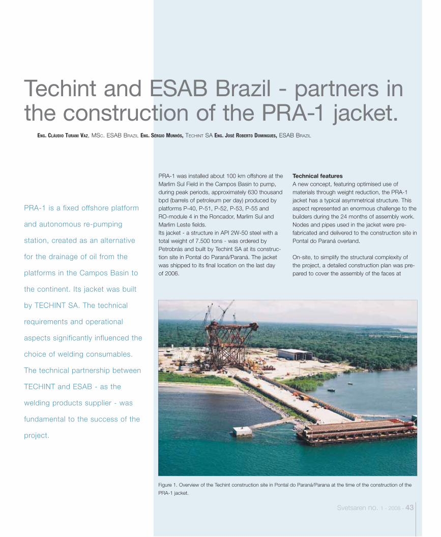
Figure 1. Overview of the Techint construction site in Pontal do Paraná/Parana at the time of the construction of the
PRA-1 jacket.
Svetsaren no. 1 - 2008 - 43
PRA-1 is a fixed offshore platform
and autonomous re-pumping
station, created as an alternative
for the drainage of oil from the
platforms in the Campos Basin to
the continent. Its jacket was built
by TECHINT SA. The technical
requirements and operational
aspects significantly influenced the
choice of welding consumables.
The technical partnership between
TECHINT and ESAB - as the
welding products supplier - was
fundamental to the success of the
project.
PRA-1 was installed about 100 km offshore at the Marlim Sul Field in the Campos Basin to pump, during peak periods, approximately 630 thousand bpd (barrels of petroleum per day) produced by platforms P-40, P-51, P-52, P-53, P-55 and RO-module 4 in the Roncador, Marlim Sul and Marlim Leste fields. Its jacket - a structure in API 2W-50 steel with a total weight of 7.500 tons - was ordered by Petrobrás and built by Techint SA at its construc-tion site in Pontal do Paraná/Paraná. The jacket was shipped to its final location on the last day of 2006.
Technical features A new concept, featuring optimised use of materials through weight reduction, the PRA-1 jacket has a typical asymmetrical structure. This aspect represented an enormous challenge to the builders during the 24 months of assembly work. Nodes and pipes used in the jacket were pre-fabricated and delivered to the construction site in Pontal do Paraná overland.
On-site, to simplify the structural complexity of the project, a detailed construction plan was pre-pared to cover the assembly of the faces at
ENG. CLÁUDIO TURANI VAZ, MSC. ESAB BRAZIL ENG. SÉRGIO MUNHÓS, TECHINT SA ENG. JOSÉ ROBERTO DOMINGUES, ESAB BRAZIL
Techint and ESAB Brazil - partners in the construction of the PRA-1 jacket.

Table 1. PRA-1 technical data
Depth 106 metres
Pumping capacity 750 thousand bpd
Deck67 metres x 53 metres x 41 metres
Number of modules 5
Accommodation 90 people
Investment US $2.7 billion
Jacket
Steel API 2W-50
Total weight 7,500 tons (approx)
Height 116 metres
Base 56 metres x 56 metres
Top 36 metres x 49 metres
44 - Svetsaren no. 1 - 2008
ground level, “roll up”, cable support and final consolidation by the fixation of tubular elements.
The assembly sequence was established after struc-tural analysis of the faces and levels of the jacket. Welding, mostly of circumferential joints, was per-formed following strict quality criteria and productivity. Wherever possible, the welding of the tubular elements was executed in the pipe shop using the submerged arc welding process (SAW). The remaining welds were performed in the field using TIG welding (GTAW) or stick electrodes (SMAW) for root passes, and flux cored wires (FCAW) or stick electrodes (SMAW) for filling and capping. The jacket’s production complied with the Petrobras norm N-1852 construction criteria (Oceanic structures - production and assembly of fixed units). This norm states that steels used in construction should be classified in conformity with Petrobrás norm N-1678 (Oceanic Structures - steel). The jacket’s design temperature was 10°C. The API 2W-50 steel used in the produc-tion of the jacket was re-classified in accordance with norm N-1678.
Welding consumables Welding consumables used in the construction of the platform jacket were supplied in agreement with the conditions defined by Petrobrás norm N-1859 - Welding consumables with quality assurance. In order to meet these requirements,
Figure 3. Joint geometry
Figure 2. Overview of the jacket in its final assembly phase.
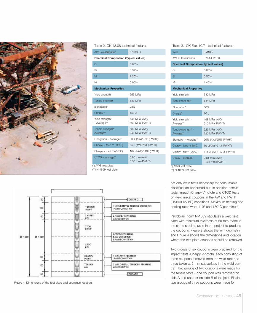
Svetsaren no. 1 - 2008 - 45
Table 2. OK 48.08 technical features
AWS classification E7018-G
Chemical Composition (Typical values)
C 0.05%
Si 0.37%
Mn 1.25%
Ni 0.90%
Mechanical Properties
Yield strength* 555 MPa
Tensile strength* 630 MPa
Elongation* 28%
Charpy * 153 J
Yield strength* - Average**
545 MPa (AW)/ 560 MPa (PWHT)
Tensile strength* - Average**
633 MPa (AW)/ 645 MPa (PWHT)
Elongation – Average** 30% (AW)/27% (PWHT)
Charpy – face ** (-30°C) 85 J (AW)/79J (PWHT)
Charpy – root ** (-30°C) 109 J(AW)/146J (PWHT)
CTOD – average** 0.86 mm (AW/0.50 mm (PWHT)
(*) AWS test plate(**) N-1859 test plate
Table 3. OK Flux 10.71 technical features
Wire EM13K
AWS Classification F7A4-EM13K
Chemical Composition (typical values)
C 0.05%
Si 0.50%
Mn 1.40%
Mechanical Properties
Yield strength* 542 MPa
Tensile strength* 644 MPa
Elongation* 30%
Charpy* 76 J
Yield strength* - Average**
498 MPa (AW)/ 510 MPa (PWHT)
Tensile strength* - Average**
626 MPa (AW)/620 MPa (PWHT)
Elongation – Average** 26% (AW)/25% (PWHT)
Charpy – face** (-30°C) 59 J(AW)/ 91 J (PWHT)
Charpy – root** (-30°C) 115 J (AW)/147 J (PWHT)
CTOD – average** 0.81 mm (AW)/ 0.94 mm (PWHT)
(*) AWS test plate(**) N-1859 test plate
Figure 4. Dimensions of the test plate and specimen location.
not only were tests necessary for consumable classification performed but, in addition, tensile tests, impact (Charpy V-notch) and CTOD tests on weld metal coupons in the AW and PWHT (2h/600-650°C) conditions. Maximum heating and cooling rates were 110° and 130°C per minute. Petrobras’ norm N-1859 stipulates a weld test plate with minimum thickness of 50 mm made in the same steel as used in the project to produce the coupons. Figure 3 shows the joint geometry and Figure 4 shows the dimensions and location where the test plate coupons should be removed.
Two groups of six coupons were prepared for the impact tests (Charpy V-notch); each consisting of three coupons removed from the weld root and three taken at 2 mm subsurface in the weld cen-tre. Two groups of two coupons were made for the tensile tests - one coupon was removed on side A and another on side B of the joint. Finally, two groups of three coupons were made for
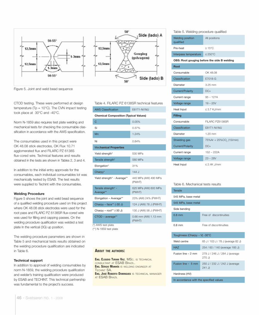
46 - Svetsaren no. 1 - 2008
ABOUT THE AUTHORS:
ENG. CLÁUDIO TURANI VAZ, MSC. IS TECHNICAL CONSULTANT AT ESAB BRAZIL. ENG. SÉRGIO MUNHÓS IS WELDING ENGINEER AT TECHINT SA. ENG. JOSÉ ROBERTO DOMINGUES IS TECHNICAL MANAGER AT ESAB BRAZIL
Table 4. FILARC PZ 6138SR technical features
AWS Classification E81T1-Ni1MJ
Chemical Composition (Typical Values)
C 0.05%
Si 0.37%
Mn 1.24%
Ni 0.84%
Mechanical Properties
Yield strength* 530 MPa
Tensile strength* 580 MPa
Elongation* 31%
Charpy* 144 J
Yield strength* - Average** 445 MPa (AW) 490 MPa (PWHT)
Tensile strength* - Average**
625 MPa (AW) 600 MPa (PWHT)
Elongation – Average** 23% (AW) 24% (PWHT)
Charpy – face** (-30 J) 124 J (AW) 78 J (PWHT)
Charpy – root** (-30 J) 130 J (AW) 58 J (PWHT)
CTOD – average** 0.66 mm (AW) 1.13 mm (PWHT)
(*) AWS test plate(**) N-1859 test plate
Table 5. Welding procedure qualified
Welding position qualified
All positions
Pre-heat 15°C
Interpass temperature 250°C
OBS: Root gouging before the side B welding
Root
Consumable OK 48.08
Classification E7018-G
Diameter 3.25 mm
Current/Polarity DC+
Current range 95 – 127A
Voltage range 19 – 25V
Heat Input 3.7 KJ/mm
Filling
Consumable FILARC PZ6138SR
Classification E81T1-Ni1MJ
Diameter 1.20 mm
Shielding gas 75%Ar + 25%CO2 (15l/min)
Current/Polarity DC+
Current range 152 – 222A
Voltage range 23 – 28V
Heat Input 2.4K J/mm
Table 6. Mechanical tests results
Tensile
545 MPa, base metal
545 MPa, base metal
Side bending
0.8 mm Free of discontinuities
0.8 mm Free of discontinuities
Toughness (Charpy – V) -30°C
Weld centre 65 J / 103 J / 78 J (average 82 J)
HAZ 254 / 60 / 140 (average 185 J)
Fusion line – 2 mm 279 J / 246 J / 284 J (average 270 J)
Fusion line – 5 mm 250 J / 232 J / 242 J (average 241 J)
Hardness (HV)
In accordance with the specified values
Figure 5. Joint and weld bead sequence
CTOD testing. These were performed at design temperature (Tp = 10°C). The CVN impact testing took place at 30°C and -40°C.
Norm N-1859 also requires test plate welding and mechanical tests for checking the consumable clas-sification in accordance with the AWS specification.
The consumables used in this project were OK 48.08 stick electrodes, OK Flux 10.71 agglomerated flux and FILARC PZ 6138S flux-cored wire. Technical features and results obtained in the tests are shown in Tables 2, 3 and 4.
In addition to the initial entry approvals for the consumables, each individual consumables lot was mechanically tested by ESAB. The test results were supplied to Techint with the consumables.
Welding ProcedureFigure 5 shows the joint and weld bead sequence of a qualified welding procedure used on this project where OK 48.08 stick electrodes were used for the root pass and FILARC PZ 6138SR flux-cored wire was used for filling and capping passes. On the welding procedure qualification was welded a test plate In the vertical (3G) up position.
The welding procedure parameters are shown in Table 5 and mechanical tests results obtained on the welding procedure qualification are indicated in Table 6.
Technical support In addition to approval of welding consumables by norm N-1859, the welding procedure qualification and welder’s training qualification were produced by ESAB and TECHINT. This technical partnership was fundamental to the project’s success.
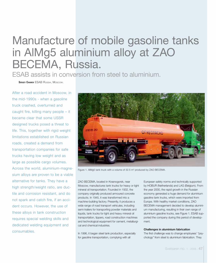
ESAB assists in conversion from steel to aluminium.
Svetsaren no. 1 - 2008 - 47
Figure 1. AlMg5 tank truck with a volume of 32.5 m3 produced by ZAO BECEMA.
After a road accident in Moscow, in
the mid-1990s - when a gasoline
truck crashed, overturned and
caught fire, killing many people – it
became clear that some USSR
designed trucks posed a threat to
life. This, together with rigid weight
limitations established on Russian
roads, created a demand from
transportation companies for safe
trucks having low weight and as
large as possible cargo volumes.
Across the world, aluminium-magne-
sium alloys are proven to be a viable
alternative for tanks. They have a
high strength/weight ratio, are duc-
tile and corrosion resistant, and do
not spark and catch fire, if an acci-
dent occurs. However, the use of
these alloys in tank construction
requires special welding skills and
dedicated welding equipment and
consumables.
SERGEY CHAMOV ESAB RUSSIA, MOSCOW.
Manufacture of mobile gasoline tanks in AlMg5 aluminium alloy at ZAO BECEMA, Russia.
European safety norms and technically supported by HOBUR (Netherlands) and LAG (Belgium). From the year 2000, the rapid growth in the Russian economy generated a huge demand for aluminium gasoline tank trucks, which were imported from Europe. With healthy market conditions, ZAO BECEMA management decided to develop alumini-um manufacturing, resulting in their own range of aluminium gasoline trucks, see Figure 1. ESAB sup-ported the company during this period of develop-ment.
Challenges in aluminium fabricationThe first challenge was to change employees’ “psy-chology” from steel to aluminium fabrication. They
ZAO BECEMA, located in Krasnogorsk, near Moscow, manufactures tank trucks for heavy or light mineral oil transportation. Founded in 1932, the company originally produced armoured concrete products. In 1945, it was transformed into a machine-building factory. Presently, it produces a wide range of road transport vehicules, including semi-trailers for transporting powder materials and liquids, tank trucks for light and heavy mineral oil transportation, tippers, road construction machines and technological equipment for cement, metallurgi-cal and chemical industries.
In 1996, it began steel tank production, especially for gasoline transportation, complying with all
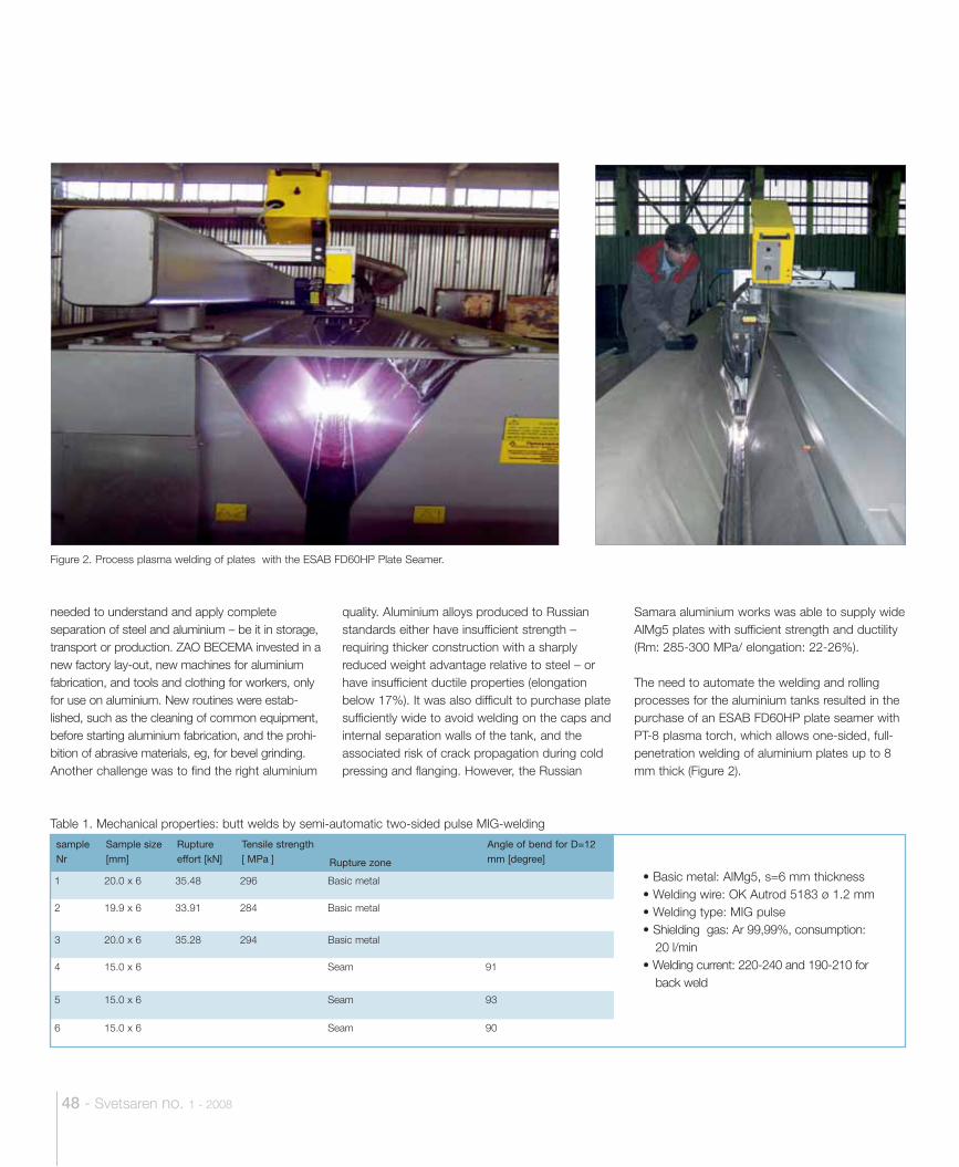
Table 1. Mechanical properties: butt welds by semi-automatic two-sided pulse MIG-welding
sample Nr
Sample size [mm]
Rupture effort [kN]
Tensile strength [ MPa ] Rupture zone
Angle of bend for D=12 mm [degree]
1 20.0 x 6 35.48 296 Basic metal
2 19.9 x 6 33.91 284 Basic metal
3 20.0 x 6 35.28 294 Basic metal
4 15.0 x 6 Seam 91
5 15.0 x 6 Seam 93
6 15.0 x 6 Seam 90
• Basic metal: AlMg5, s=6 mm thickness• Welding wire: OK Autrod 5183 ø 1.2 mm• Welding type: MIG pulse• Shielding gas: Ar 99,99%, consumption:
20 l/min• Welding current: 220-240 and 190-210 for
back weld
48 - Svetsaren no. 1 - 2008
Figure 2. Process plasma welding of plates with the ESAB FD60HP Plate Seamer.
needed to understand and apply complete separation of steel and aluminium – be it in storage, transport or production. ZAO BECEMA invested in a new factory lay-out, new machines for aluminium fabrication, and tools and clothing for workers, only for use on aluminium. New routines were estab-lished, such as the cleaning of common equipment, before starting aluminium fabrication, and the prohi-bition of abrasive materials, eg, for bevel grinding. Another challenge was to find the right aluminium
quality. Aluminium alloys produced to Russian standards either have insufficient strength – requiring thicker construction with a sharply reduced weight advantage relative to steel – or have insufficient ductile properties (elongation below 17%). It was also difficult to purchase plate sufficiently wide to avoid welding on the caps and internal separation walls of the tank, and the associated risk of crack propagation during cold pressing and flanging. However, the Russian
Samara aluminium works was able to supply wide AlMg5 plates with sufficient strength and ductility (Rm: 285-300 MPa/ elongation: 22-26%). The need to automate the welding and rolling processes for the aluminium tanks resulted in the purchase of an ESAB FD60HP plate seamer with PT-8 plasma torch, which allows one-sided, full-penetration welding of aluminium plates up to 8 mm thick (Figure 2).
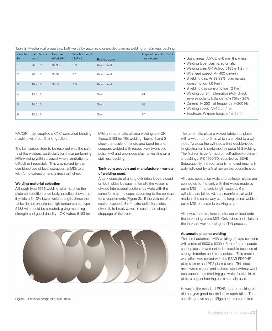
• Basic metal: AlMg5, s=6 mm thickness• Welding type: plasma automatic• Welding wire: OK Autrod 5183 ø 1.2 mm • Wire feed speed V= 400 cm/min• Shielding gas: Ar 99,99%, plasma gas
consumption 1.6 l/min • Shielding gas consumption 12 l/min• Welding current: alternative (AC), direct/
reverse polarity balance (+/-) 75% / 25% • Current I= 250 at frequency f=200 Hz• Welding speed V=16 cm/min• Electrode: W (pure tungsten) ø 5 mm
Svetsaren no. 1 - 2008 - 49
MIG and automatic plasma welding and OK Tigrod 5183 for TIG welding. Tables 1 and 2 show the results of tensile and bend tests on coupons welded with respectively two-sided pulse MIG and one-sided plasma welding on a stainless backing.
Tank construction and manufacture - variety of welding used.A tank consists of a long cylindrical body, closed on both sides by caps. Internally the vessel is divided into several sections by walls with the same form as the caps, according to the contrac-tor’s requirements (Figure 3). If the volume of a section exceeds 8 m3, extra deflector plates divide it, to break waves in case of an abrupt stoppage of the truck.
The automatic plasma welder fabricates plates with a width up to 6 m, which are rolled to a cyl-inder. To close the cylinder, a final double-sided longitudinal run is performed by pulse MIG welding. The first run is performed on self-adhesive ceram-ic backings, PZ 1500/70, supplied by ESAB. Subsequently, the root area is removed mechani-cally, followed by a final run on the opposite side.
All caps, separation walls and deflector plates are connected to the tank with fillet welds made by pulse MIG. If the tank length exceeds 6 m, cylinders are joined with a circumferential weld made in the same way as the longitudinal welds – pulse MIG on ceramic backing strip.
All boxes, ladders, fences, etc, are welded onto the tank using pulse MIG. Only tubes and inlets to the tank are welded using the TIG process.
Automatic plasma welding The semi-automatic MIG welding of plate sections with a size of 6000 x 6300 x 6 mm from separate sheet plates proved not to be feasible because of strong distortion and many defects. This problem was effectively solved with the ESAB FD60HP plate seamer and PT-8 plasma torch. This equip-ment welds carbon and stainless steel without weld pool support and shielding gas while, for aluminium plate, a copper backing bar is normally used.
However, the standard ESAB copper backing bar did not give good results in this application. The specific groove shape (Figure 4), promotes free
Table 2. Mechanical properties: butt welds by automatic one-sided plasma welding on stainless backing.
sample Nr
Sample size [mm]
Rupture effort [kN]
Tensile strength [ MPa ] Rupture zone
Angle of bend for D=12 mm [degree]
1 20.0 6 32.93 274 Basic metal
2 20.0 6 33.32 278 Basic metal
3 19.9 6 33.12 277 Basic metal
4 15.0 6 Seam 94
5 15.0 6 Seam 98
6 15.0 6 Seam 97
Figure 3. Principal design of a truck tank.
FACCIN, Italy, supplied a CNC-controlled bending machine with four 6 m long rollers.
The last serious item to be resolved was the safe-ty of the welders, particularly for those performing MIG-welding within a vessel where ventilation is difficult or impossible. This was solved by the combined use of local extraction, a MIG torch with fume extraction and a fresh air helmet.
Welding material selectionAlthough type 5356 welding wire matches the plate composition chemically, practice shows that it yields a 5-10% lower weld strength. Since the tanks do not experience high temperatures, type 5183 wire could be selected, giving matching strength and good ductility - OK Autrod 5183 for
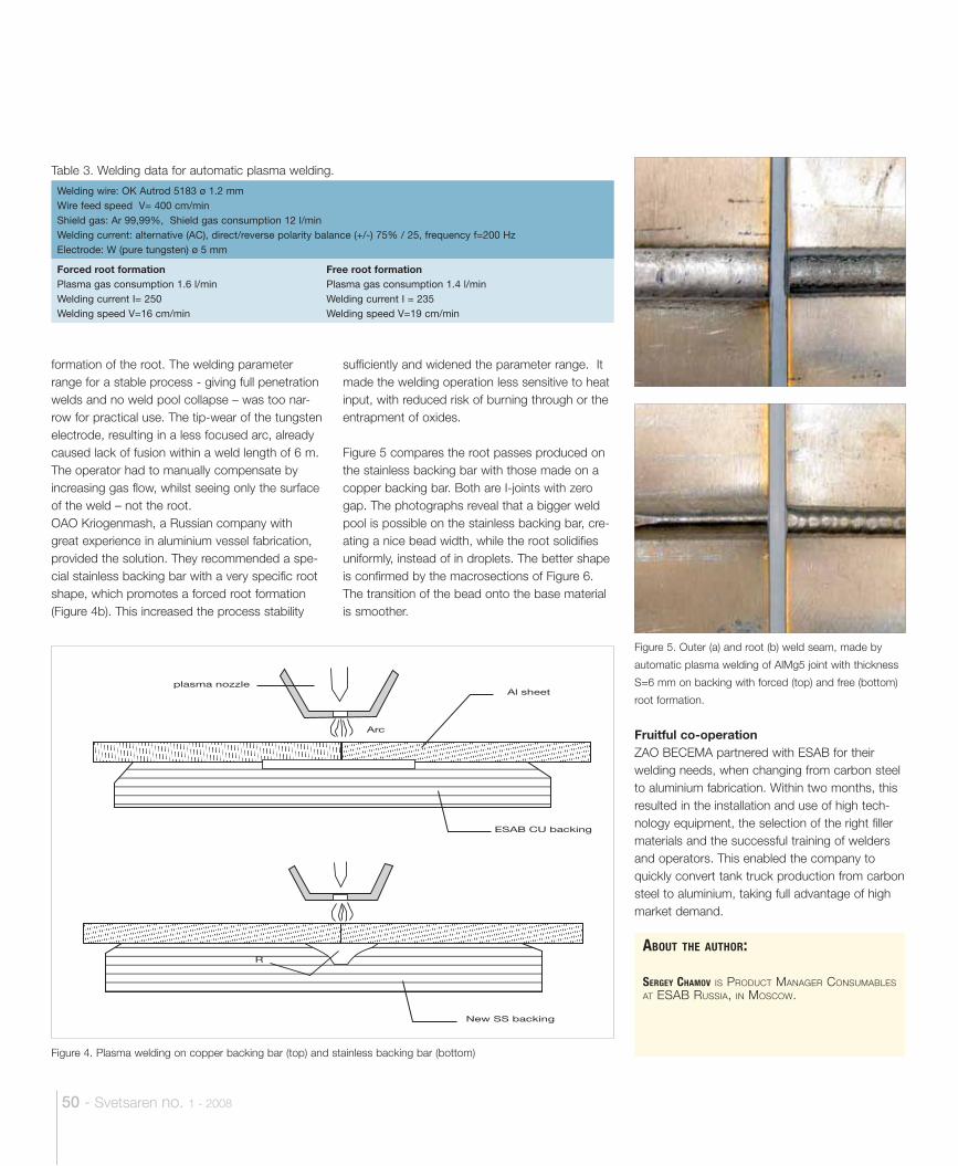
50 - Svetsaren no. 1 - 2008
ABOUT THE AUTHOR:
SERGEY CHAMOV IS PRODUCT MANAGER CONSUMABLES AT ESAB RUSSIA, IN MOSCOW.
formation of the root. The welding parameter range for a stable process - giving full penetration welds and no weld pool collapse – was too nar-row for practical use. The tip-wear of the tungsten electrode, resulting in a less focused arc, already caused lack of fusion within a weld length of 6 m. The operator had to manually compensate by increasing gas flow, whilst seeing only the surface of the weld – not the root. OAO Kriogenmash, a Russian company with great experience in aluminium vessel fabrication, provided the solution. They recommended a spe-cial stainless backing bar with a very specific root shape, which promotes a forced root formation (Figure 4b). This increased the process stability
Table 3. Welding data for automatic plasma welding.
Welding wire: OK Autrod 5183 ø 1.2 mmWire feed speed V= 400 cm/minShield gas: Ar 99,99%, Shield gas consumption 12 l/minWelding current: alternative (AC), direct/reverse polarity balance (+/-) 75% / 25, frequency f=200 HzElectrode: W (pure tungsten) ø 5 mm
Forced root formationPlasma gas consumption 1.6 l/minWelding current I= 250 Welding speed V=16 cm/min
Free root formationPlasma gas consumption 1.4 l/minWelding current I = 235 Welding speed V=19 cm/min
R
New SS backing
plasma nozzle
Arc
Al sheet
ESAB CU backing
Figure 4. Plasma welding on copper backing bar (top) and stainless backing bar (bottom)
Figure 5. Outer (a) and root (b) weld seam, made by
automatic plasma welding of AlMg5 joint with thickness
S=6 mm on backing with forced (top) and free (bottom)
root formation.
sufficiently and widened the parameter range. It made the welding operation less sensitive to heat input, with reduced risk of burning through or the entrapment of oxides.
Figure 5 compares the root passes produced on the stainless backing bar with those made on a copper backing bar. Both are I-joints with zero gap. The photographs reveal that a bigger weld pool is possible on the stainless backing bar, cre-ating a nice bead width, while the root solidifies uniformly, instead of in droplets. The better shape is confirmed by the macrosections of Figure 6. The transition of the bead onto the base material is smoother.
Fruitful co-operationZAO BECEMA partnered with ESAB for their welding needs, when changing from carbon steel to aluminium fabrication. Within two months, this resulted in the installation and use of high tech-nology equipment, the selection of the right filler materials and the successful training of welders and operators. This enabled the company to quickly convert tank truck production from carbon steel to aluminium, taking full advantage of high market demand.
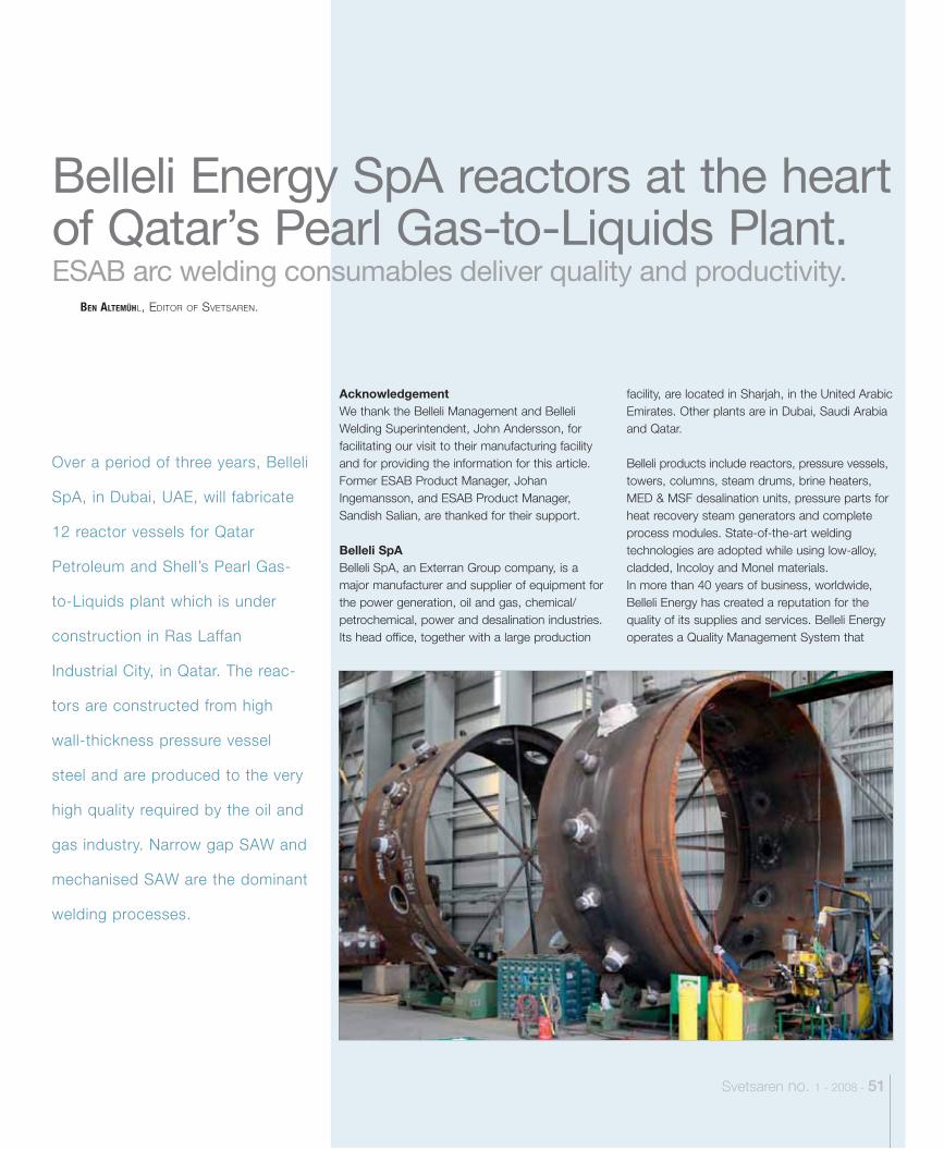
ESAB arc welding consumables deliver quality and productivity.
Svetsaren no. 1 - 2008 - 51
AcknowledgementWe thank the Belleli Management and Belleli Welding Superintendent, John Andersson, for facilitating our visit to their manufacturing facility and for providing the information for this article. Former ESAB Product Manager, Johan Ingemansson, and ESAB Product Manager, Sandish Salian, are thanked for their support.
Belleli SpABelleli SpA, an Exterran Group company, is a major manufacturer and supplier of equipment for the power generation, oil and gas, chemical/petrochemical, power and desalination industries. Its head office, together with a large production
facility, are located in Sharjah, in the United Arabic Emirates. Other plants are in Dubai, Saudi Arabia and Qatar.
Belleli products include reactors, pressure vessels, towers, columns, steam drums, brine heaters, MED & MSF desalination units, pressure parts for heat recovery steam generators and complete process modules. State-of-the-art welding technologies are adopted while using low-alloy, cladded, Incoloy and Monel materials. In more than 40 years of business, worldwide, Belleli Energy has created a reputation for the quality of its supplies and services. Belleli Energy operates a Quality Management System that
Over a period of three years, Belleli
SpA, in Dubai, UAE, will fabricate
12 reactor vessels for Qatar
Petroleum and Shell’s Pearl Gas-
to-Liquids plant which is under
construction in Ras Laffan
Industrial City, in Qatar. The reac-
tors are constructed from high
wall-thickness pressure vessel
steel and are produced to the very
high quality required by the oil and
gas industry. Narrow gap SAW and
mechanised SAW are the dominant
welding processes.
BEN ALTEMÜHL, EDITOR OF SVETSAREN.
Belleli Energy SpA reactors at the heart of Qatar’s Pearl Gas-to-Liquids Plant.
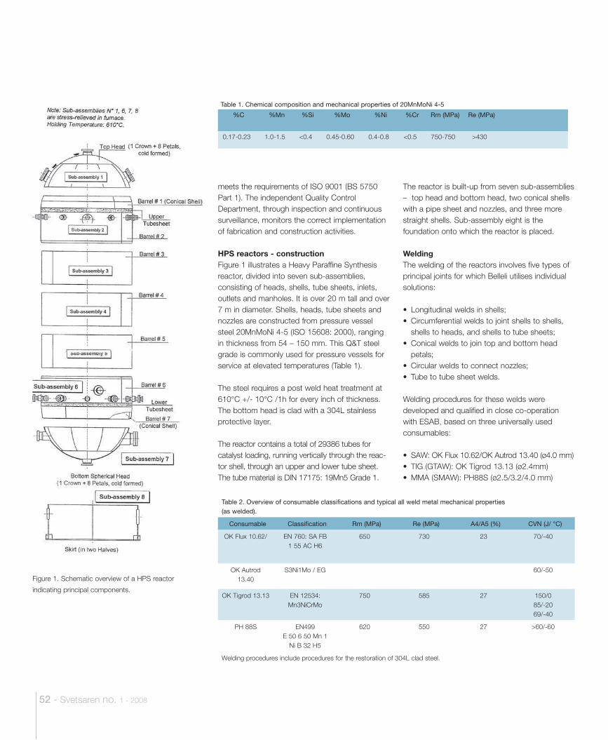
52 - Svetsaren no. 1 - 2008
meets the requirements of ISO 9001 (BS 5750 Part 1). The independent Quality Control Department, through inspection and continuous surveillance, monitors the correct implementation of fabrication and construction activities.
HPS reactors - constructionFigure 1 illustrates a Heavy Paraffine Synthesis reactor, divided into seven sub-assemblies, consisting of heads, shells, tube sheets, inlets, outlets and manholes. It is over 20 m tall and over 7 m in diameter. Shells, heads, tube sheets and nozzles are constructed from pressure vessel steel 20MnMoNi 4-5 (ISO 15608: 2000), ranging in thickness from 54 – 150 mm. This Q&T steel grade is commonly used for pressure vessels for service at elevated temperatures (Table 1).
The steel requires a post weld heat treatment at 610°C +/- 10°C /1h for every inch of thickness. The bottom head is clad with a 304L stainless protective layer.
The reactor contains a total of 29386 tubes for catalyst loading, running vertically through the reac-tor shell, through an upper and lower tube sheet. The tube material is DIN 17175: 19Mn5 Grade 1.
The reactor is built-up from seven sub-assemblies – top head and bottom head, two conical shells with a pipe sheet and nozzles, and three more straight shells. Sub-assembly eight is the foundation onto which the reactor is placed.
WeldingThe welding of the reactors involves five types of principal joints for which Belleli utilises individual solutions:
• Longitudinal welds in shells;• Circumferential welds to joint shells to shells,
shells to heads, and shells to tube sheets;• Conical welds to join top and bottom head
petals;• Circular welds to connect nozzles;• Tube to tube sheet welds.
Welding procedures for these welds were developed and qualified in close co-operation with ESAB, based on three universally used consumables:
• SAW: OK Flux 10.62/OK Autrod 13.40 (ø4.0 mm)• TIG (GTAW): OK Tigrod 13.13 (ø2.4mm)• MMA (SMAW): PH88S (ø2.5/3.2/4.0 mm)
Table 1. Chemical composition and mechanical properties of 20MnMoNi 4-5
%C %Mn %Si %Mo %Ni %Cr Rm (MPa) Re (MPa)
0.17-0.23 1.0-1.5 <0.4 0.45-0.60 0.4-0.8 <0.5 750-750 >430
Table 2. Overview of consumable classifications and typical all weld metal mechanical properties (as welded).
Consumable Classification Rm (MPa) Re (MPa) A4/A5 (%) CVN (J/ °C)
OK Flux 10.62/ EN 760: SA FB 1 55 AC H6
650 730 23 70/-40
OK Autrod 13.40
S3Ni1Mo / EG 60/-50
OK Tigrod 13.13 EN 12534: Mn3NiCrMo
750 585 27 150/085/-2069/-40
PH 88S EN499E 50 6 50 Mn 1
Ni B 32 H5
620 550 27 >60/-60
Welding procedures include procedures for the restoration of 304L clad steel.
Figure 1. Schematic overview of a HPS reactor
indicating principal components.
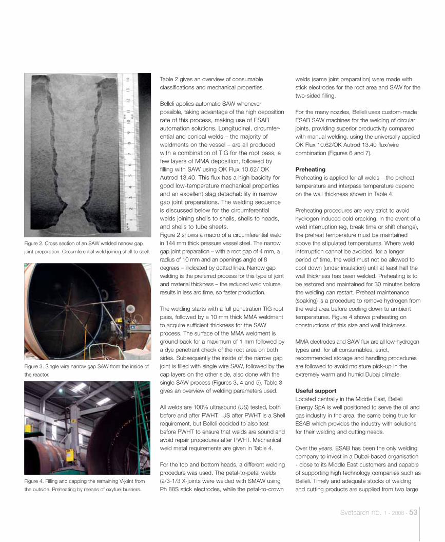
Svetsaren no. 1 - 2008 - 53
Table 2 gives an overview of consumable classifications and mechanical properties.
Belleli applies automatic SAW whenever possible, taking advantage of the high deposition rate of this process, making use of ESAB automation solutions. Longitudinal, circumfer-ential and conical welds – the majority of weldments on the vessel – are all produced with a combination of TIG for the root pass, a few layers of MMA deposition, followed by filling with SAW using OK Flux 10.62/ OK Autrod 13.40. This flux has a high basicity for good low-temperature mechanical properties and an excellent slag detachability in narrow gap joint preparations. The welding sequence is discussed below for the circumferential welds joining shells to shells, shells to heads, and shells to tube sheets.Figure 2 shows a macro of a circumferential weld in 144 mm thick pressure vessel steel. The narrow gap joint preparation – with a root gap of 4 mm, a radius of 10 mm and an openings angle of 8 degrees – indicated by dotted lines. Narrow gap welding is the preferred process for this type of joint and material thickness – the reduced weld volume results in less arc time, so faster production.
The welding starts with a full penetration TIG root pass, followed by a 10 mm thick MMA weldment to acquire sufficient thickness for the SAW process. The surface of the MMA weldment is ground back for a maximum of 1 mm followed by a dye penetrant check of the root area on both sides. Subsequently the inside of the narrow gap joint is filled with single wire SAW, followed by the cap layers on the other side, also done with the single SAW process (Figures 3, 4 and 5). Table 3 gives an overview of welding parameters used.
All welds are 100% ultrasound (US) tested, both before and after PWHT. US after PWHT is a Shell requirement, but Belleli decided to also test before PWHT to ensure that welds are sound and avoid repair procedures after PWHT. Mechanical weld metal requirements are given in Table 4.
For the top and bottom heads, a different welding procedure was used. The petal-to-petal welds (2/3-1/3 X-joints were welded with SMAW using Ph 88S stick electrodes, while the petal-to-crown
welds (same joint preparation) were made with stick electrodes for the root area and SAW for the two-sided filling.
For the many nozzles, Belleli uses custom-made ESAB SAW machines for the welding of circular joints, providing superior productivity compared with manual welding, using the universally applied OK Flux 10.62/OK Autrod 13.40 flux/wire combination (Figures 6 and 7).
PreheatingPreheating is applied for all welds – the preheat temperature and interpass temperature depend on the wall thickness shown in Table 4.
Preheating procedures are very strict to avoid hydrogen induced cold cracking. In the event of a weld interruption (eg, break time or shift change), the preheat temperature must be maintained above the stipulated temperatures. Where weld interruption cannot be avoided, for a longer period of time, the weld must not be allowed to cool down (under insulation) until at least half the wall thickness has been welded. Preheating is to be restored and maintained for 30 minutes before the welding can restart. Preheat maintenance (soaking) is a procedure to remove hydrogen from the weld area before cooling down to ambient temperatures. Figure 4 shows preheating on constructions of this size and wall thickness.
MMA electrodes and SAW flux are all low-hydrogen types and, for all consumables, strict, recommended storage and handling procedures are followed to avoid moisture pick-up in the extremely warm and humid Dubai climate.
Useful supportLocated centrally in the Middle East, Belleli Energy SpA is well positioned to serve the oil and gas industry in the area, the same being true for ESAB which provides the industry with solutions for their welding and cutting needs.
Over the years, ESAB has been the only welding company to invest in a Dubai-based organisation - close to its Middle East customers and capable of supporting high technology companies such as Belleli. Timely and adequate stocks of welding and cutting products are supplied from two large
Figure 2. Cross section of an SAW welded narrow gap
joint preparation. Circumferential weld joining shell to shell.
Figure 3. Single wire narrow gap SAW from the inside of
the reactor.
Figure 4. Filling and capping the remaining V-joint from
the outside. Preheating by means of oxyfuel burners.
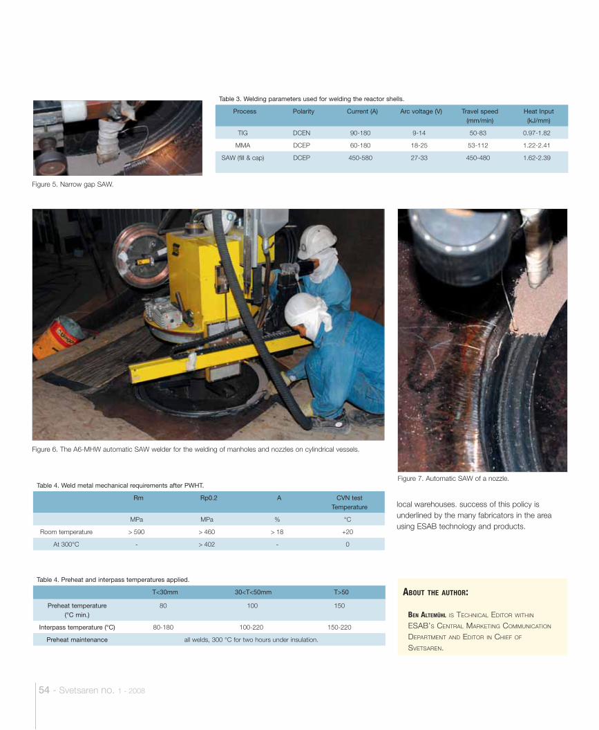
54 - Svetsaren no. 1 - 2008
ABOUT THE AUTHOR:
BEN ALTEMÜHL IS TECHNICAL EDITOR WITHIN ESAB’S CENTRAL MARKETING COMMUNICATION DEPARTMENT AND EDITOR IN CHIEF OF SVETSAREN.
local warehouses. success of this policy is underlined by the many fabricators in the area using ESAB technology and products.
Table 3. Welding parameters used for welding the reactor shells.
Process Polarity Current (A) Arc voltage (V) Travel speed (mm/min)
Heat Input (kJ/mm)
TIG DCEN 90-180 9-14 50-83 0.97-1.82
MMA DCEP 60-180 18-25 53-112 1.22-2.41
SAW (fill & cap) DCEP 450-580 27-33 450-480 1.62-2.39
Table 4. Preheat and interpass temperatures applied.
T<30mm 30<T<50mm T>50
Preheat temperature (°C min.)
80 100 150
Interpass temperature (°C) 80-180 100-220 150-220
Preheat maintenance all welds, 300 °C for two hours under insulation.
Table 4. Weld metal mechanical requirements after PWHT.
Rm Rp0.2 A CVN test Temperature
MPa MPa % °C
Room temperature 590 460 18 +20
At 300°C - 402 - 0
Figure 5. Narrow gap SAW.
Figure 6. The A6-MHW automatic SAW welder for the welding of manholes and nozzles on cylindrical vessels.
Figure 7. Automatic SAW of a nozzle.
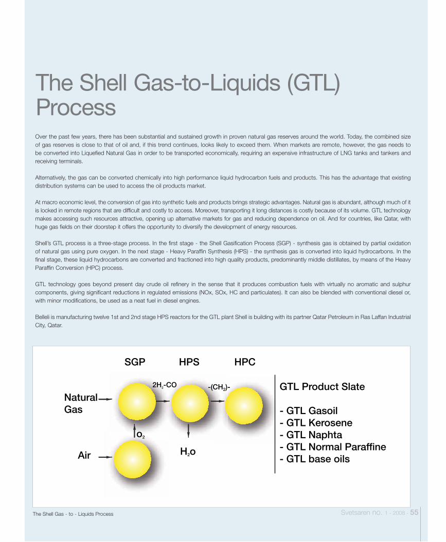
NaturalGas
o2
2H2-CO -(CH2)-
H2o
GTL Product Slate
- GTL Gasoil- GTL Kerosene- GTL Naphta- GTL Normal Paraffine- GTL base oils
SGP HPS HPC
Air
Svetsaren no. 1 - 2008 - 55
The Shell Gas-to-Liquids (GTL) ProcessOver the past few years, there has been substantial and sustained growth in proven natural gas reserves around the world. Today, the combined size of gas reserves is close to that of oil and, if this trend continues, looks likely to exceed them. When markets are remote, however, the gas needs to be converted into Liquefied Natural Gas in order to be transported economically, requiring an expensive infrastructure of LNG tanks and tankers and receiving terminals.
Alternatively, the gas can be converted chemically into high performance liquid hydrocarbon fuels and products. This has the advantage that existing distribution systems can be used to access the oil products market.
At macro economic level, the conversion of gas into synthetic fuels and products brings strategic advantages. Natural gas is abundant, although much of it is locked in remote regions that are difficult and costly to access. Moreover, transporting it long distances is costly because of its volume. GTL technology makes accessing such resources attractive, opening up alternative markets for gas and reducing dependence on oil. And for countries, like Qatar, with huge gas fields on their doorstep it offers the opportunity to diversify the development of energy resources.
Shell’s GTL process is a three-stage process. In the first stage - the Shell Gasification Process (SGP) - synthesis gas is obtained by partial oxidation of natural gas using pure oxygen. In the next stage - Heavy Paraffin Synthesis (HPS) - the synthesis gas is converted into liquid hydrocarbons. In the final stage, these liquid hydrocarbons are converted and fractioned into high quality products, predominantly middle distillates, by means of the Heavy Paraffin Conversion (HPC) process.
GTL technology goes beyond present day crude oil refinery in the sense that it produces combustion fuels with virtually no aromatic and sulphur components, giving significant reductions in regulated emissions (NOx, SOx, HC and particulates). It can also be blended with conventional diesel or, with minor modifications, be used as a neat fuel in diesel engines.
Belleli is manufacturing twelve 1st and 2nd stage HPS reactors for the GTL plant Shell is building with its partner Qatar Petroleum in Ras Laffan Industrial City, Qatar.
The Shell Gas - to - Liquids Process
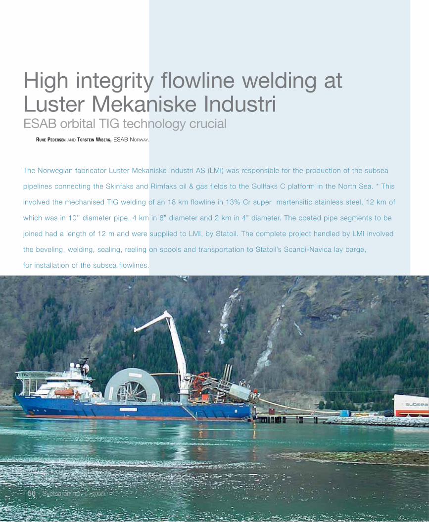
56 - Svetsaren no. 1 - 2008
ESAB orbital TIG technology crucial
The Norwegian fabricator Luster Mekaniske Industri AS (LMI) was responsible for the production of the subsea
pipelines connecting the Skinfaks and Rimfaks oil & gas fields to the Gullfaks C platform in the North Sea. * This
involved the mechanised TIG welding of an 18 km flowline in 13% Cr super martensitic stainless steel, 12 km of
which was in 10’’ diameter pipe, 4 km in 8” diameter and 2 km in 4” diameter. The coated pipe segments to be
joined had a length of 12 m and were supplied to LMI, by Statoil. The complete project handled by LMI involved
the beveling, welding, sealing, reeling on spools and transportation to Statoil’s Scandi-Navica lay barge,
for installation of the subsea flowlines.
RUNE PEDERSEN AND TORSTEIN WIBERG, ESAB NORWAY.
High integrity flowline welding at Luster Mekaniske Industri
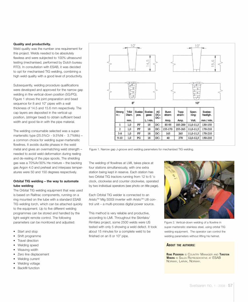
Svetsaren no. 1 - 2008 - 57
Quality and productivity. Weld quality was the number one requirement for this project. Welds needed to be absolutely flawless and were subjected to 100% ultrasound testing (mechanised, performed by Dutch bureau RTD). In consultation with ESAB, it was decided to opt for mechanised TIG welding, combining a high weld quality with a good level of productivity.
Subsequently, welding procedure qualifications were developed and approved for the narrow gap welding in the vertical-down position (5G/PG). Figure 1 shows the joint preparation and bead sequence for 8 and 10” pipes with a wall thickness of 14.5 and 15.6 mm respectively. The cap layers are deposited in the vertical-up position, (stringer bead) to obtain sufficient bead width and good tie-in with the pipe material.
The welding consumable selected was a super-martensitic type (25.5%Cr - 9.5%Ni - 3.7%Mo) – a common choice for welding super-martensitic flowlines. It avoids ductile phases in the weld metal and gives an overmatching weld strength – needed to avoid weld deformation during reeling and de-reeling of the pipe spools. The shielding gas was a 70%Ar/30% He mixture – the backing gas Argon 4.0 and preheat and interpass temper-atures were 50 and 150 degrees respectively.
Orbital TIG welding – the way to automate tube weldingThe Orbital TIG welding equipment that was used is based on Railtrac components, running on a ring mounted on the tube with a standard ESAB TIG welding torch, which can be attached quickly to the equipment. Up to five different welding programmes can be stored and handled by the light-weight remote control. The following parameters can be monitored and adjusted:
• Start and stop• Shift programme• Travel direction• Welding speed• Weaving width• Zero line displacement• Welding current• Welding voltage• Backfill function
The welding of flowlines at LMI, takes place at four stations simultaneously, with one extra station being kept in reserve. Each station has two Orbital TIG tractors running from 12 to 6 ‘o clock, clockwise and counter clockwise, operated by two individual operators (see photo on title page).
Each Orbital TIG welder is connected to an AristoTM Mig 5000i inverter with AristoTM U8 con-trol unit – a multi-process digital power source.
This method is very reliable and productive, according to LMI. Throughout the Skinfaks/Rimfaks project, some 2500 welds were US tested with only 5 showing a weld defect. It took about 15 minutes for a complete weld to be finished on an 8 or 10” pipe.
Figure 1. Narrow gap J-groove and welding parameters for mechanized TIG welding.
Figure 2. Vertical-down welding of a flowline in
super-martensitic stainless steel, using orbital TIG
welding equipment. The operator can control the
welding parameters without lifting his helmet.
ABOUT THE AUTHORS:
RUNE PEDERSEN IS COUNTRY MANAGER AND TORSTEIN WIBERG IS SALES REPRESENTATIVE AT ESAB NORWAY, LARVIK, NORWAY.
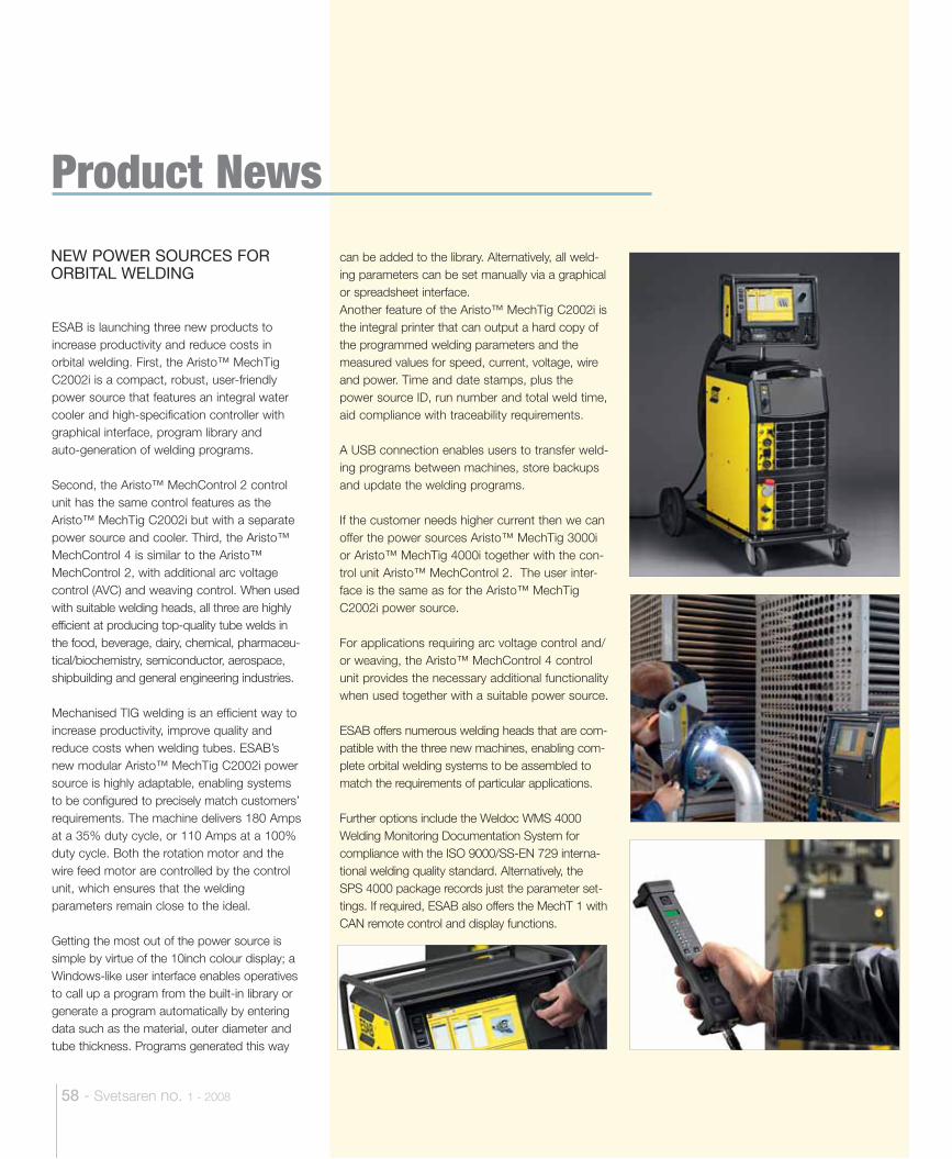
58 - Svetsaren no. 1 - 2008
Product News
ESAB is launching three new products to increase productivity and reduce costs in orbital welding. First, the Aristo™ MechTig C2002i is a compact, robust, user-friendly power source that features an integral water cooler and high-specification controller with graphical interface, program library and auto-generation of welding programs.
Second, the Aristo™ MechControl 2 control unit has the same control features as the Aristo™ MechTig C2002i but with a separate power source and cooler. Third, the Aristo™ MechControl 4 is similar to the Aristo™ MechControl 2, with additional arc voltage control (AVC) and weaving control. When used with suitable welding heads, all three are highly efficient at producing top-quality tube welds in the food, beverage, dairy, chemical, pharmaceu-tical/biochemistry, semiconductor, aerospace, shipbuilding and general engineering industries.
Mechanised TIG welding is an efficient way to increase productivity, improve quality and reduce costs when welding tubes. ESAB’s new modular Aristo™ MechTig C2002i power source is highly adaptable, enabling systems to be configured to precisely match customers’ requirements. The machine delivers 180 Amps at a 35% duty cycle, or 110 Amps at a 100% duty cycle. Both the rotation motor and the wire feed motor are controlled by the control unit, which ensures that the welding parameters remain close to the ideal.
Getting the most out of the power source is simple by virtue of the 10inch colour display; a Windows-like user interface enables operatives to call up a program from the built-in library or generate a program automatically by entering data such as the material, outer diameter and tube thickness. Programs generated this way
can be added to the library. Alternatively, all weld-ing parameters can be set manually via a graphical or spreadsheet interface.Another feature of the Aristo™ MechTig C2002i is the integral printer that can output a hard copy of the programmed welding parameters and the measured values for speed, current, voltage, wire and power. Time and date stamps, plus the power source ID, run number and total weld time, aid compliance with traceability requirements.
A USB connection enables users to transfer weld-ing programs between machines, store backups and update the welding programs.
If the customer needs higher current then we can offer the power sources Aristo™ MechTig 3000i or Aristo™ MechTig 4000i together with the con-trol unit Aristo™ MechControl 2. The user inter-face is the same as for the Aristo™ MechTig C2002i power source.
For applications requiring arc voltage control and/or weaving, the Aristo™ MechControl 4 control unit provides the necessary additional functionality when used together with a suitable power source.
ESAB offers numerous welding heads that are com-patible with the three new machines, enabling com-plete orbital welding systems to be assembled to match the requirements of particular applications.
Further options include the Weldoc WMS 4000 Welding Monitoring Documentation System for compliance with the ISO 9000/SS-EN 729 interna-tional welding quality standard. Alternatively, the SPS 4000 package records just the parameter set-tings. If required, ESAB also offers the MechT 1 with CAN remote control and display functions.
NEW POWER SOURCES FOR ORBITAL WELDING
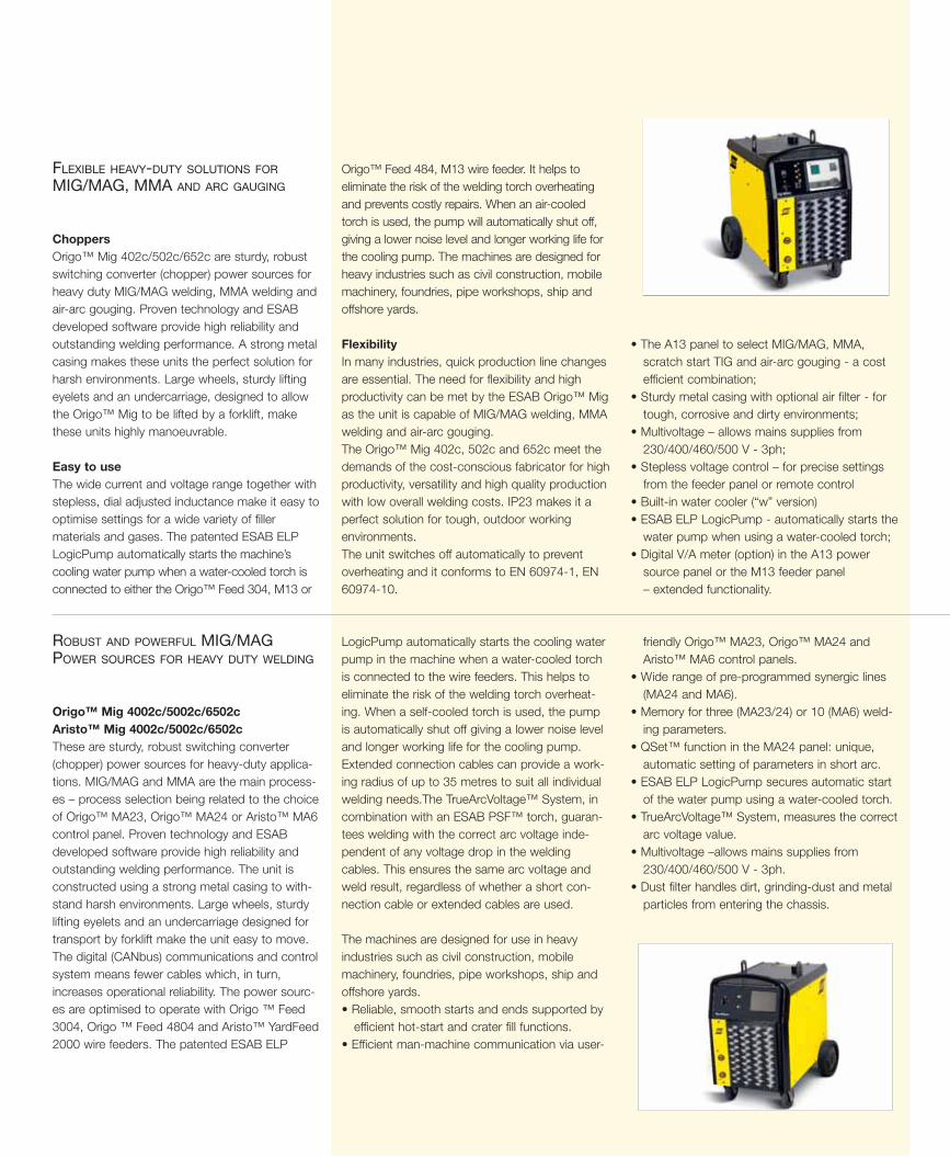
Choppers Origo™ Mig 402c/502c/652c are sturdy, robust switching converter (chopper) power sources for heavy duty MIG/MAG welding, MMA welding and air-arc gouging. Proven technology and ESAB developed software provide high reliability and outstanding welding performance. A strong metal casing makes these units the perfect solution for harsh environments. Large wheels, sturdy lifting eyelets and an undercarriage, designed to allow the Origo™ Mig to be lifted by a forklift, make these units highly manoeuvrable.
Easy to useThe wide current and voltage range together with stepless, dial adjusted inductance make it easy to optimise settings for a wide variety of filler materials and gases. The patented ESAB ELP LogicPump automatically starts the machine’s cooling water pump when a water-cooled torch is connected to either the Origo™ Feed 304, M13 or
Origo™ Feed 484, M13 wire feeder. It helps to eliminate the risk of the welding torch overheating and prevents costly repairs. When an air-cooled torch is used, the pump will automatically shut off, giving a lower noise level and longer working life for the cooling pump. The machines are designed for heavy industries such as civil construction, mobile machinery, foundries, pipe workshops, ship and offshore yards.
Flexibility In many industries, quick production line changes are essential. The need for flexibility and high productivity can be met by the ESAB Origo™ Mig as the unit is capable of MIG/MAG welding, MMA welding and air-arc gouging. The Origo™ Mig 402c, 502c and 652c meet the demands of the cost-conscious fabricator for high productivity, versatility and high quality production with low overall welding costs. IP23 makes it a perfect solution for tough, outdoor working environments.The unit switches off automatically to prevent overheating and it conforms to EN 60974-1, EN 60974-10.
• The A13 panel to select MIG/MAG, MMA, scratch start TIG and air-arc gouging - a cost efficient combination;
• Sturdy metal casing with optional air filter - for tough, corrosive and dirty environments;
• Multivoltage – allows mains supplies from 230/400/460/500 V - 3ph;
• Stepless voltage control – for precise settings from the feeder panel or remote control
• Built-in water cooler (“w” version)• ESAB ELP LogicPump - automatically starts the
water pump when using a water-cooled torch;• Digital V/A meter (option) in the A13 power
source panel or the M13 feeder panel – extended functionality.
FLEXIBLE HEAVY-DUTY SOLUTIONS FOR MIG/MAG, MMA AND ARC GAUGING
ROBUST AND POWERFUL MIG/MAG POWER SOURCES FOR HEAVY DUTY WELDING
Origo™ Mig 4002c/5002c/6502cAristo™ Mig 4002c/5002c/6502cThese are sturdy, robust switching converter (chopper) power sources for heavy-duty applica-tions. MIG/MAG and MMA are the main process-es – process selection being related to the choice of Origo™ MA23, Origo™ MA24 or Aristo™ MA6 control panel. Proven technology and ESAB developed software provide high reliability and outstanding welding performance. The unit is constructed using a strong metal casing to with-stand harsh environments. Large wheels, sturdy lifting eyelets and an undercarriage designed for transport by forklift make the unit easy to move. The digital (CANbus) communications and control system means fewer cables which, in turn, increases operational reliability. The power sourc-es are optimised to operate with Origo ™ Feed 3004, Origo ™ Feed 4804 and Aristo™ YardFeed 2000 wire feeders. The patented ESAB ELP
LogicPump automatically starts the cooling water pump in the machine when a water-cooled torch is connected to the wire feeders. This helps to eliminate the risk of the welding torch overheat-ing. When a self-cooled torch is used, the pump is automatically shut off giving a lower noise level and longer working life for the cooling pump. Extended connection cables can provide a work-ing radius of up to 35 metres to suit all individual welding needs.The TrueArcVoltage™ System, in combination with an ESAB PSF™ torch, guaran-tees welding with the correct arc voltage inde-pendent of any voltage drop in the welding cables. This ensures the same arc voltage and weld result, regardless of whether a short con-nection cable or extended cables are used.
The machines are designed for use in heavy industries such as civil construction, mobile machinery, foundries, pipe workshops, ship and offshore yards.• Reliable, smooth starts and ends supported by
efficient hot-start and crater fill functions.• Efficient man-machine communication via user-
friendly Origo™ MA23, Origo™ MA24 and Aristo™ MA6 control panels.
• Wide range of pre-programmed synergic lines (MA24 and MA6).
• Memory for three (MA23/24) or 10 (MA6) weld-ing parameters.
• QSet™ function in the MA24 panel: unique, automatic setting of parameters in short arc.
• ESAB ELP LogicPump secures automatic start of the water pump using a water-cooled torch.
• TrueArcVoltage™ System, measures the correct arc voltage value.
• Multivoltage –allows mains supplies from 230/400/460/500 V - 3ph.
• Dust filter handles dirt, grinding-dust and metal particles from entering the chassis.

60 - Svetsaren no. 1 - 2008
Caddy™ is the perfect partner in both MMA and TIG welding. From the single-phase Caddy™ Arc 151i A31 to the top-of- the-line Caddy™ Tig 2200i AC/DC, this family of portable welding units offers robust, reliable and flexible performance. Compact and efficient inverter technology, user-friendly multifunctional control panels and intelligent software assure optimal welding parameters and a consistently stable arc. And when things get hot, the Caddy™ stays cool – thanks to smart design.
Designed to lastCaddy™ features user-friendly control panels and compact, portable, impact and flame-resistant polymer housing. Inside, large heat sinks and smart design ensure cool operation for extended service life in harsh environments, while all sensitive components are fully shielded from dust and other particulates. Equipped with large high-durability OKC 50cable connectors, these IP23 compliant Caddy™ units can be used outdoors – even in rain. Superior performance, unsurpassed reliability – day after day.
Power Factor Correction (PFC)The Caddy™ units are equipped with PFC circuits. These enable operation at full capacity on standard 16 A or 10 A fuses, for improved economy. Complying with the latest EMC (Electromagnetic Compatibility) legislation, PFC protects the machine from fluctuating primary voltage, for consistent performance and enhanced safety, even when connected to a generator. Caddy™ permits the use of mains cables longer than 100 metres to extend working radius.
Caddy™ Arc 151i/201iOffering fully professional performance (150 A-170 A at 25% duty cycle), the portability and attractive pricing of these robust and compact single-phase machines places them in reach of skilled enthusiasts as well as seasoned professionals.
The Caddy™ Arc 151i/201i is the perfect welding tool for on-site installation, maintenance, repair or fabrication – indoors and outdoors.
Gloves-on controlWhether you choose the basic one-knob A31 or the advanced A33 panel you need never take your gloves off: both are easy to understand and set. The digital display A33 is a true multifunctional panel, featuring hot-start and arc force control (to fine-tune the welding process), choice of MMA or TIG welding, LiveTig™ start in TIG mode, two program function and an analogue remote control option. Control panel Caddy™ A33 has the latest regulator, ArcPlus™ II that gives a more intense, yet smooth and stable arc that is easy to control.
The go-anywhere welding partnerThe single-phase Caddy™ Arc is the ideal MMA partner for welding most metals, including alloyed/non-alloyed steel, stainless steel and cast iron. Designed for most grades of electrodes, from Ø1.6 up to Ø 4 mm, these machines offer exceptional reliability and consistent performance. The multi-functionality of the advanced A33 control panel and enhanced welding characteristics of the ArcPlus™ II software (smoother burning arc, less
CADDY™ - THE PORTABLE SOLUTION FOR PROFESSIONAL WELDING
Caddy™ Arc 151i/201i
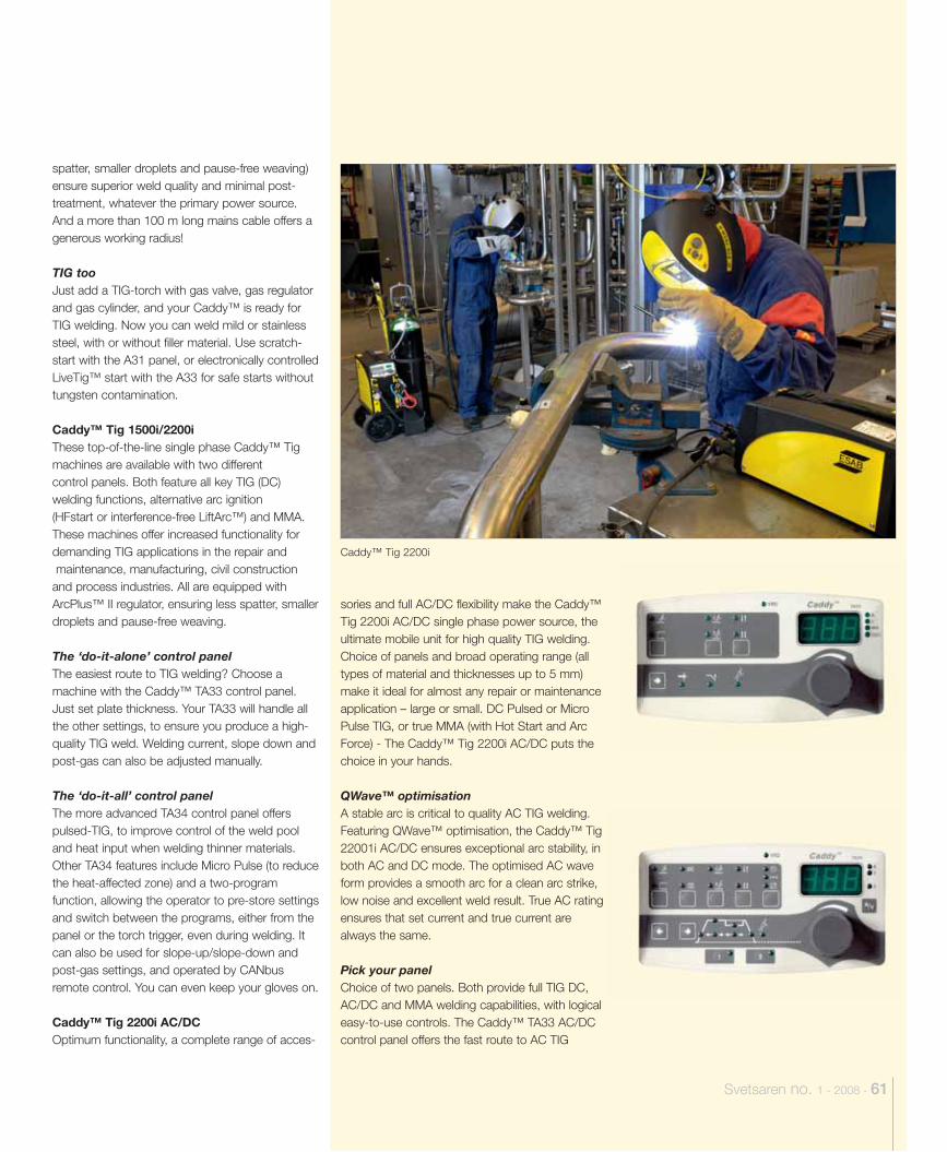
Svetsaren no. 1 - 2008 - 61
spatter, smaller droplets and pause-free weaving) ensure superior weld quality and minimal post-treatment, whatever the primary power source. And a more than 100 m long mains cable offers a generous working radius!
TIG tooJust add a TIG-torch with gas valve, gas regulator and gas cylinder, and your Caddy™ is ready for TIG welding. Now you can weld mild or stainless steel, with or without filler material. Use scratch-start with the A31 panel, or electronically controlled LiveTig™ start with the A33 for safe starts without tungsten contamination.
Caddy™ Tig 1500i/2200i These top-of-the-line single phase Caddy™ Tig machines are available with two differentcontrol panels. Both feature all key TIG (DC) welding functions, alternative arc ignition(HFstart or interference-free LiftArc™) and MMA. These machines offer increased functionality for demanding TIG applications in the repair and maintenance, manufacturing, civil construction and process industries. All are equipped with ArcPlus™ II regulator, ensuring less spatter, smaller droplets and pause-free weaving.
The ‘do-it-alone’ control panelThe easiest route to TIG welding? Choose a machine with the Caddy™ TA33 control panel. Just set plate thickness. Your TA33 will handle all the other settings, to ensure you produce a high-quality TIG weld. Welding current, slope down and post-gas can also be adjusted manually.
The ‘do-it-all’ control panelThe more advanced TA34 control panel offers pulsed-TIG, to improve control of the weld pool and heat input when welding thinner materials. Other TA34 features include Micro Pulse (to reduce the heat-affected zone) and a two-program function, allowing the operator to pre-store settings and switch between the programs, either from the panel or the torch trigger, even during welding. It can also be used for slope-up/slope-down and post-gas settings, and operated by CANbus remote control. You can even keep your gloves on.
Caddy™ Tig 2200i AC/DCOptimum functionality, a complete range of acces-
sories and full AC/DC flexibility make the Caddy™ Tig 2200i AC/DC single phase power source, the ultimate mobile unit for high quality TIG welding. Choice of panels and broad operating range (all types of material and thicknesses up to 5 mm) make it ideal for almost any repair or maintenance application – large or small. DC Pulsed or Micro Pulse TIG, or true MMA (with Hot Start and Arc Force) - The Caddy™ Tig 2200i AC/DC puts the choice in your hands.
QWave™ optimisationA stable arc is critical to quality AC TIG welding. Featuring QWave™ optimisation, the Caddy™ Tig 22001i AC/DC ensures exceptional arc stability, in both AC and DC mode. The optimised AC wave form provides a smooth arc for a clean arc strike, low noise and excellent weld result. True AC rating ensures that set current and true current are always the same.
Pick your panelChoice of two panels. Both provide full TIG DC, AC/DC and MMA welding capabilities, with logical easy-to-use controls. The Caddy™ TA33 AC/DC control panel offers the fast route to AC TIG
Caddy™ Tig 2200i
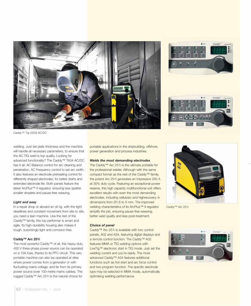
62 - Svetsaren no. 1 - 2008
welding. Just set plate thickness and the machine will handle all necessary parameters, to ensure that the AC TIG weld is top quality. Looking for advanced functionality? The Caddy™ TA34 AC/DC has it all. AC Balance control for arc cleaning and penetration, AC Frequency control to set arc width. It also features an electrode preheating control for differently shaped electrodes, for better starts and extended electrode life. Both panels feature the latest ArcPlus™ II regulator, ensuring less spatter, smaller droplets and pause-free weaving.
Light and easyIn a repair shop or aboard an oil rig, with the tight deadlines and constant movement from site to site, you need a lean machine. Like the rest of the Caddy™ family, this top performer is smart and agile. Its high-durability housing also makes it tough, surprisingly light and corrosion-free.
Caddy™ Arc 251iThe most powerful Caddy™ of all, this heavy-duty 400 V three-phase power source can be operated on a 10A fuse, thanks to its PFC circuit. This very portable machine can also be operated at sites where power comes from a generator or with fluctuating mains voltage, and far from its primary power source (over 100-metre mains cables). The rugged Caddy™ Arc 251i is the natural choice for
portable applications in the shipbuilding, offshore, power generation and process industries.
Welds the most demanding electrodesThe Caddy™ Arc 251i is the ultimate portable for the professional welder. Although with the same compact format as the rest of the Caddy™ family, the potent Arc 251i generates an impressive 250 A at 30% duty cycle. Featuring an exceptional power reserve, this high capacity multifunctional unit offers excellent results with even the most demanding electrodes, including cellulosic and highrecovery, in dimensions from Ø1.6 to 5 mm. The improved welding characteristics of its ArcPlus™ II regulator simplify the job, ensuring pause-free weaving, better weld quality and less post-treatment.
Choice of panelCaddy™ Arc 251i is available with two control panels, A32 and A34, featuring digital displays and a remote control function. The Caddy™ A32 features MMA or TIG welding options with LiveTig™ electronic start in TIG mode. Just set the welding current and you’re ready. The more advanced Caddy™ A34 features additional functions such as hot-start and arc force control and two program function. The specific electrode type may be selected in MMA mode, automatically optimising welding performance.
Caddy™ Tig 2200i AC/DC
Caddy™ Arc 251i
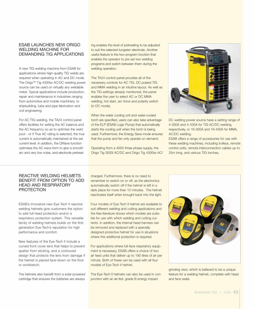
Svetsaren no. 1 - 2008 - 63
A new TIG welding machine from ESAB for applications where high-quality TIG welds are required when operating in AC and DC mode. The OrigoTM Tig 4300iw AC/DC welding power source can be used on virtually any weldable metal. Typical applications include production, repair and maintenance in industries ranging from automotive and mobile machinery, to shipbuilding, tube and pipe fabrication and civil engineering.
For AC TIG welding, the TA24 control panel offers facilities for setting the AC balance and the AC frequency so as to optimise the weld pool - or if True AC rating is selected, the true current is automatically maintained at the set current level. In addition, the QWave function optimises the AC wave form to give a smooth arc and very low noise, and electrode preheat-
ing enables the level of preheating to be adjusted to suit the selected tungsten electrode. Another useful feature is the two-program function that enables the operator to pre-set two welding programs and switch between them during the welding operation.
The TA24 control panel provides all of the necessary controls for AC TIG, DC pulsed TIG and MMA welding in an intuitive layout. As well as the TIG settings already mentioned, the panel enables the user to select AC or DC MMA welding, hot start, arc force and polarity switch (in DC mode).
When the water cooling unit and water-cooled torch are specified, users can also take advantage of the ELP (ESAB Logic Pump) that automatically starts the cooling unit when the torch is being used. Furthermore, the Energy Save mode ensures that the pump and fan only operate on demand.
Operating from a 400V three-phase supply, the Origo Tig 3000i AC/DC and Origo Tig 4300iw AC/
DC welding power source hase a setting range of 4-300A and 4-430A for TIG AC/DC welding, respectively, or 16-300A and 16-430A for MMA, AC/DC welding.ESAB offers a range of accessories for use with these welding machines, including trolleys, remote control units, remote interconnection cables up to 25m long, and various TIG torches.
ESAB LAUNCHES NEW ORIGO WELDING MACHINE FOR DEMANDING TIG APPLICATIONS
charged. Furthermore, there is no need to remember to switch on or off, as the electronics automatically switch off if the helmet is left in a dark place for more than 10 minutes. The helmet reactivates itself when brought back into the light.
Four models of Eye-Tech II helmet are available to suit different welding and cutting applications and the free literature shows which models are suita-ble for use with which welding and cutting cur-rents. In addition, the internal head harness can be removed and replaced with a specially designed protective helmet for use in situations where this additional protection is required.
For applications where full-face respiratory equip-ment is necessary, ESAB offers a choice of two air feed units that deliver up to 190 litres of air per minute. Both of these can be used with all four models of Eye-Tech II helmet.
The Eye-Tech II helmets can also be used in con-junction with an air-fed, grade B energy impact
grinding visor, which is believed to be a unique feature for a welding helmet, complete with head and face seals.
ESAB’s innovative new Eye-Tech II reactive welding helmets give customers the option to add full head protection and/or a respiratory protection system. This versatile family of welding helmets builds on the first-generation Eye-Tech’s reputation for high performance and comfort.
New features of the Eye-Tech II include a curved front cover lens that helps to prevent spatter from sticking, and a contoured design that protects the lens from damage if the helmet is placed face-down on the floor or workbench.
The helmets also benefit from a solar-powered cartridge that ensures the batteries are always
REACTIVE WELDING HELMETS BENEFIT FROM OPTION TO ADD HEAD AND RESPIRATORY PROTECTION
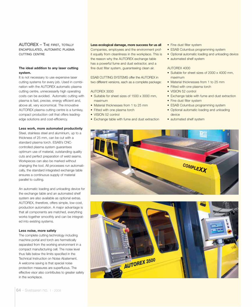
64 - Svetsaren no. 1 - 2008
The ideal addition to any laser cutting system.It is not necessary to use expensive laser cutting systems for every job. Used in combi-nation with the AUTOREX automatic plasma cutting centre, unnecessarily high operating costs can be avoided. Automatic cutting with plasma is fast, precise, energy efficient and, above all, very economical. The innovative AUTOREX plasma cutting centre is a turnkey, compact production cell that offers leading-edge solutions and cost-efficiency.
Less work, more automated productivitySteel, stainless steel and aluminium, up to a thickness of 25 mm, can be cut with a standard plasma torch. ESAB’s CNC-controlled plasma system guarantees optimum use of material, outstanding quality cuts and perfect preparation of weld seams. Workpieces can also be marked without changing the tool. All processes run automati-cally, the standard integrated exchange table ensures a continuous supply of material parallel to cutting.
An automatic loading and unloading device for the exchange table and an automated shelf system are also available as optional extras. AUTOREX, therefore, offers simple, low-cost, production automation. A major advantage is that all components are matched, everything works together smoothly and can be integrat-ed into existing systems.
Less noise, more safetyThe complete cutting technology including machine portal and torch are hermetically separated from the working environment in a compact manufacturing cell. The noise level thus falls below the limits specified in the Technical Instruction on Noise Abatement. A welcome saving is that special noise protection measures are superfluous. The effective visor also contributes to greater safety in the workplace.
Less ecological damage, more success for us allCompanies, employees and the environment prof-it equally from cleanliness in the workplace. This is the reason why the AUTOREX exchange table has a powerful fume and dust extractor, and a fine dust filter system, guaranteeing clean air.
ESAB CUTTING SYSTEMS offer the AUTOREX in two different versions, each as a complete package:
AUTOREX 3000 • Suitable for sheet sizes of 1500 x 3000 mm,
maximum• Material thicknesses from 1 to 25 mm• Fitted with one plasma torch• VISION 52 control• Exchange table with fume and dust extraction
AUTOREX – THE FIRST, TOTALLY ENCAPSULATED, AUTOMATIC PLASMA CUTTING CENTRE
• Fine dust filter system• ESAB Columbus programming system• Optional automatic loading and unloading device• automated shelf system
AUTOREX 4000 • Suitable for sheet sizes of 2000 x 4000 mm,
maximum• Material thicknesses from 1 to 25 mm• Fitted with one plasma torch• VISION 52 control• Exchange table with fume and dust extraction• Fine dust filter system• ESAB Columbus programming system• Optional automatic loading and unloading
device• automated shelf system
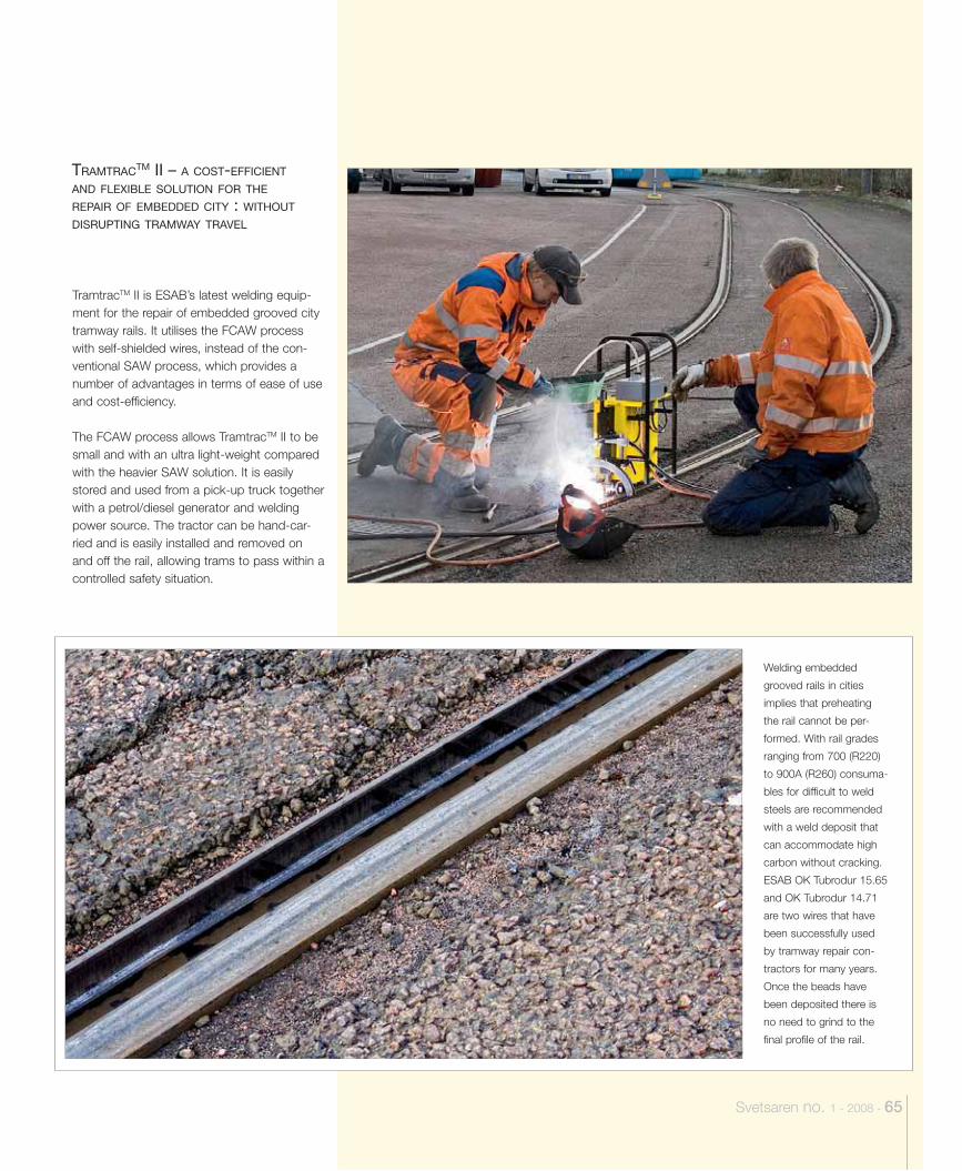
Welding embedded
grooved rails in cities
implies that preheating
the rail cannot be per-
formed. With rail grades
ranging from 700 (R220)
to 900A (R260) consuma-
bles for difficult to weld
steels are recommended
with a weld deposit that
can accommodate high
carbon without cracking.
ESAB OK Tubrodur 15.65
and OK Tubrodur 14.71
are two wires that have
been successfully used
by tramway repair con-
tractors for many years.
Once the beads have
been deposited there is
no need to grind to the
final profile of the rail.
Svetsaren no. 1 - 2008 - 65
TramtracTM II is ESAB’s latest welding equip-ment for the repair of embedded grooved city tramway rails. It utilises the FCAW process with self-shielded wires, instead of the con-ventional SAW process, which provides a number of advantages in terms of ease of use and cost-efficiency.
The FCAW process allows TramtracTM II to be small and with an ultra light-weight compared with the heavier SAW solution. It is easily stored and used from a pick-up truck together with a petrol/diesel generator and welding power source. The tractor can be hand-car-ried and is easily installed and removed on and off the rail, allowing trams to pass within a controlled safety situation.
TRAMTRACTM II – A COST-EFFICIENT
AND FLEXIBLE SOLUTION FOR THE
REPAIR OF EMBEDDED CITY : WITHOUT DISRUPTING TRAMWAY TRAVEL
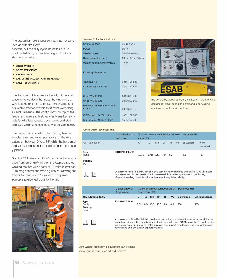
The control box features clearly marked symbols for wire
feed speed, travel speed and start and stop welding
functions, as well as wire inching.
Light-weight TramtracTM II equipment can be hand-
carried and is easily installed and removed.
66 - Svetsaren no. 1 - 2008
The deposition rate is approximately at the same level as with the SAW process, but the duty cycle increases due to quick installation, no flux handling and reduced slag removal effort.
The TramtracTM II is operator friendly with a four-wheel drive carriage that rides the single rail, a wire feeding unit for 1.2 or 1.6 mm Ø wires and adjustable traction wheels to fit most worn flang-es and railheads. The control box, on top of the feeder encasement, features clearly marked sym-bols for wire feed speed, travel speed and start and stop welding functions, as well as wire inching.
The curved slide on which the welding head is enables easy and exact positioning of the wire extension between 0 to ± 65° while the horizontal and vertical slides enable positioning in the x- and y-planes.
TramtracTM II needs a 42V AC control voltage sup-plied from an Origo™ Mig or 410 step controlled welding rectifier with a total of 40 voltage settings. 10m long control and welding cables, allowing the tractor to travel up to 17 m when the power source is positioned close to the rail.
• LIGHT WEIGHT
• COST-EFFICIENT
• PRODUCTIVE
• EASILY INSTALLED AND REMOVED
• EASY TO OPERATE
Tramtrac™ II – technical data.
Control voltage 36-46 V AC
Power 90 W
Welding speed 30-100 mm/min.
Dimensions (l x w x h) 600 x 300 x 150 mm
Weight without consumables 12 kg
Ordering information
TramtracTM II 0814 721 880
Connection cable 10m 0457 360 884
Origo™ MIG 410 0349 302 408
Origo™ MIG 320 0349 303 562
Magnetic earth return cable & clamp 0000 500 415
OK Tubrodur 14.71, 1.6mm 1471 167 730
OK Tubrodur 15.65, 1.6mm 1565 167 730
Cored wires – technical data.
Classifications & approvals
Typical chemical composition all weld metal (%)
Hardness HB
OK Tubrodur 14.71 C Si Mn Cr Ni Mo as welded work hardened
TypeRutile
PolarityDC+
EN14700 T Fe 100.026 0.48 5.12 19.1 8.7 200 400
A stainless rutile 18.8.6Mn, self-shielded cored wire for cladding and joining 13% Mn steels and steels with limited weldability. It is also useful for buffer layers prior to hardfacing. Supreme welding characteristics and excellent slag detachability.
Classifi cations & approvals
Typical chemical composition all weld metal (%)
Hardness HB
OK Tubrodur 15.65 C Si Mn Cr Ni Mo as welded work hardened
TypeRutilePolarityDC+
EN14700 T Fe 90.03 0.6 13.5 15.5 1.8 0.8 250 450
A stainless rutile self-shielded cored wire depositing a martensitic-austenitic, work harde-ning deposit, used for the rebuilding of mild, low-alloy and 13%Mn steels. The weld metal combines excellent metal to metal abrasion and impact resistance. Supreme welding cha-racteristics and excellent slag detachability.
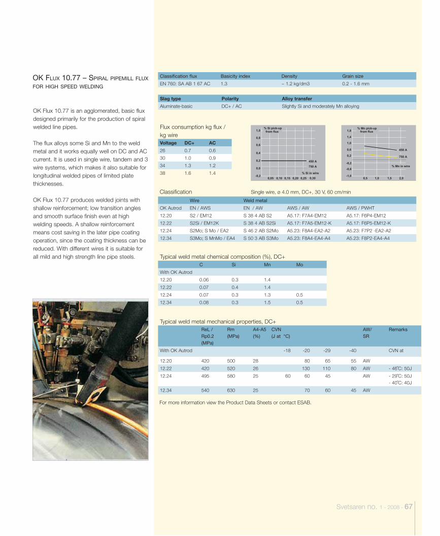
Svetsaren no. 1 - 2008 - 67
OK Flux 10.77 is an agglomerated, basic flux designed primarily for the production of spiral welded line pipes.
The flux alloys some Si and Mn to the weld metal and it works equally well on DC and AC current. It is used in single wire, tandem and 3 wire systems, which makes it also suitable for longitudinal welded pipes of limited plate thicknesses.
OK Flux 10.77 produces welded joints with shallow reinforcement; low transition angles and smooth surface finish even at high welding speeds. A shallow reinforcement means cost saving in the later pipe coating operation, since the coating thickness can be reduced. With different wires it is suitable for all mild and high strength line pipe steels.
OK FLUX 10.77 – SPIRAL PIPEMILL FLUX FOR HIGH SPEED WELDING
Classification flux Basicity index Density Grain size
EN 760: SA AB 1 67 AC 1.3 ~ 1.2 kg/dm3 0.2 - 1.6 mm
Slag type Polarity Alloy transfer
Aluminate-basic DC+ / AC Slightly Si and moderately Mn alloying
Flux consumption kg flux / kg wireVoltage DC+ AC
26 0.7 0.6
30 1.0 0.9
34 1.3 1.2
38 1.6 1.4
ClassificationWire Weld metal
OK Autrod EN / AWS EN / AW AWS / AW AWS / PWHT
12.20 S2 / EM12 S 38 4 AB S2 A5.17: F7A4-EM12 A5.17: F6P4-EM12
12.22 S2Si / EM12K S 38 4 AB S2Si A5.17: F7A5-EM12-K A5.17: F6P5-EM12-K
12.24 S2Mo; S Mo / EA2 S 46 2 AB S2Mo A5.23: F8A4-EA2-A2 A5.23: F7P2 -EA2-A2
12.34 S3Mo; S MnMo / EA4 S 50 3 AB S3Mo A5.23: F8A4-EA4-A4 A5.23: F8P2-EA4-A4
Typical weld metal chemical composition (%), DC+C Si Mn Mo
With OK Autrod
12.20 0.06 0.3 1.4
12.22 0.07 0.4 1.4
12.24 0.07 0.3 1.3 0.5
12.34 0.08 0.3 1.5 0.5
Typical weld metal mechanical properties, DC+ReL / Rp0.2(MPa)
Rm(MPa)
A4-A5(%)
CVN(J at °C)
AW/SR
Remarks
With OK Autrod -18 -20 -29 -40 CVN at
12.20 420 500 28 80 65 55 AW
12.22 420 520 26 130 110 80 AW - 46˚C: 50J
12.24 495 580 25 60 60 45 AW - 29˚C: 50J- 40˚C: 40J
12.34 540 630 25 70 60 45 AW
For more information view the Product Data Sheets or contact ESAB.
-1,0
-0,2
-0,6
0,2
0,6
1,0
1,4
1,8
0,5 1,0 1,5 2,0
% Mn pick-up
% Mn in wire
from flux
450 A
750 A
-0,2
0,0
0,2
0,4
0,6
0,8
1,0
0,05 0,10 0,15 0,20 0,25 0,30
% Si in wire
% Si pick-up from flux
450 A
750 A
Single wire, ø 4.0 mm, DC+, 30 V, 60 cm/min
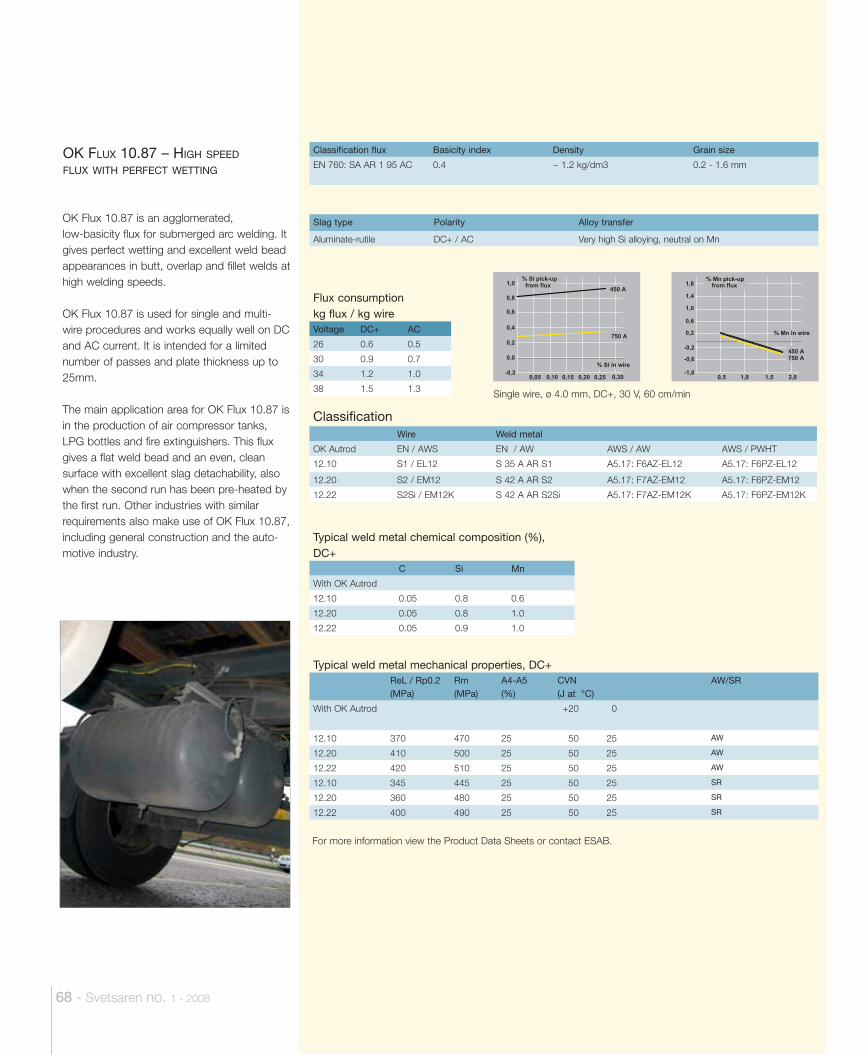
OK Flux 10.87 is an agglomerated, low-basicity flux for submerged arc welding. It gives perfect wetting and excellent weld bead appearances in butt, overlap and fillet welds at high welding speeds.
OK Flux 10.87 is used for single and multi-wire procedures and works equally well on DC and AC current. It is intended for a limited number of passes and plate thickness up to 25mm.
The main application area for OK Flux 10.87 is in the production of air compressor tanks, LPG bottles and fire extinguishers. This flux gives a flat weld bead and an even, clean surface with excellent slag detachability, also when the second run has been pre-heated by the first run. Other industries with similar requirements also make use of OK Flux 10.87, including general construction and the auto-motive industry.
OK FLUX 10.87 – HIGH SPEED FLUX WITH PERFECT WETTING
Classification flux Basicity index Density Grain size
EN 760: SA AR 1 95 AC 0.4 ~ 1.2 kg/dm3 0.2 - 1.6 mm
Slag type Polarity Alloy transfer
Aluminate-rutile DC+ / AC Very high Si alloying, neutral on Mn
Flux consumption kg flux / kg wireVoltage DC+ AC
26 0.6 0.5
30 0.9 0.7
34 1.2 1.0
38 1.5 1.3
Classifi cationWire Weld metal
OK Autrod EN / AWS EN / AW AWS / AW AWS / PWHT
12.10 S1 / EL12 S 35 A AR S1 A5.17: F6AZ-EL12 A5.17: F6PZ-EL12
12.20 S2 / EM12 S 42 A AR S2 A5.17: F7AZ-EM12 A5.17: F6PZ-EM12
12.22 S2Si / EM12K S 42 A AR S2Si A5.17: F7AZ-EM12K A5.17: F6PZ-EM12K
Typical weld metal chemical composition (%), DC+
C Si Mn
With OK Autrod
12.10 0.05 0.8 0.6
12.20 0.05 0.8 1.0
12.22 0.05 0.9 1.0
Typical weld metal mechanical properties, DC+ReL / Rp0.2(MPa)
Rm(MPa)
A4-A5(%)
CVN(J at °C)
AW/SR
With OK Autrod +20 0
12.10 370 470 25 50 25 AW
12.20 410 500 25 50 25 AW
12.22 420 510 25 50 25 AW
12.10 345 445 25 50 25 SR
12.20 360 480 25 50 25 SR
12.22 400 490 25 50 25 SR
For more information view the Product Data Sheets or contact ESAB.
-0,2
0,0
0,2
0,4
0,6
0,8
1,0
0,05 0,10 0,15 0,20 0,25 0,30
% Si in wire
% Si pick-up from flux
450 A
750 A
-1,0
-0,2
-0,6
0,2
0,6
1,0
1,4
1,8
0,5 1,0 1,5 2,0
% Mn pick-up
% Mn in wire
from flux
450 A750 A
Single wire, ø 4.0 mm, DC+, 30 V, 60 cm/min
68 - Svetsaren no. 1 - 2008
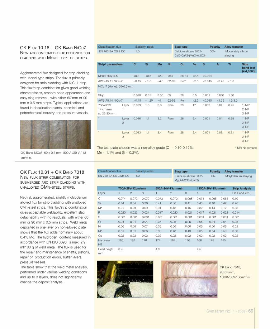
Svetsaren no. 1 - 2008 - 69
Agglomerated flux designed for strip cladding with Monel type strips. The flux is primarily designed for strip cladding with NiCu7-strip. This flux/strip combination gives good welding characteristics, smooth bead appearance and easy slag removal , with either 60 mm or 90 mm x 0.5 mm strips. Typical applications are found in desalination plants, chemical and petrochemical industry and pressure vessels.
Neutral, agglomerated, slightly molybdenum alloyed flux for strip cladding with unalloyed CMn-steel strips. This flux/strip combination gives acceptable weldability, excellent slag detachability with no residuals, with either 60 mm or 90 mm x 0.5 mm strips. Weld metal deposited in one layer on non-alloyed plate shows that the flux adds nominally about 0.4% Mo. The hydrogen content measured in accordance with EN ISO 3690, is max. 2.9 ml/100 g of weld metal. The flux is used for the repair and maintenance of shafts, pistons, repair of production errors, buffer layers, pressure vessels.The table show that the weld metal analysis, performed under various welding conditions and up to 3 layers, does not significantly change the deposit analysis.
OK FLUX 10.18 + OK BAND NICU7 NEW AGGLOMERATED FLUX DESIGNED FOR CLADDING WITH MONEL TYPE OF STRIPS.
OK FLUX 10.31 + OK BAND 7018 NEW FLUX STRIP COMBINATION FOR SUBMERGED ARC STRIP CLADDING WITH UNALLOYED CMN-STEEL STRIPS.
Classification flux Basicity index
EN 760 SA CS 2 DC 1.0
Classification flux Basicity index
EN 760 SA CS 3 Mo DC 1.0
Slag type Polarity Alloy transfer
Calcium silicate SiO2-CaO-CaF2-(MnO-Al2O3)
DC+ Moderately silicon alloying
Slag type Polarity Alloy transfer
Calcium silicate SiO2-MgO-Al2O3-(CaF2)
DC+ Molybdenum alloying
750A-28V-12cm/min 850A-24V-13cm/min 1150A-28V-15cm/min Strip Analysis
Layer 1 2 3 1 2 3 1 2 3 OK Band 7018
C 0.074 0.072 0.070 0.073 0.070 0.068 0.071 0.065 0.064 0.10
Si 0.44 0.34 0.36 0.41 0.36 0.41 0.43 0.40 0.42 0.26
Mn 0.21 0.09 0.09 0.31 0.13 0.15 0.32 0.14 0.12 0.38
P 0.020 0.023 0.024 0.017 0.020 0.021 0.017 0.021 0.022 0.014
S 0.001 0.001 0.001 0.001 0.001 0.001 0.001 0.001 0.001 0.001
Cr 0.04 0.04 0.04 0.05 0.05 0.05 0.05 0.04 0.04 0.05
Ni 0.06 0.06 0.07 0.05 0.06 0.06 0.05 0.06 0.06 0.02
Mo 0.51 0.61 0.66 0.36 0.48 0.49 0.35 0.54 0.59 0.00
Cu 0.02 0.02 0.02 0.02 0.02 0.02 0.02 0.02 0.02 0.02
Hardness HB
186 187 196 174 188 186 166 178 185
Bead height. mm
3.9 4.0 4.5
Strip/ parameters C Si Mn Ni Cu Fe S Al Ti Side bend test (4xt,180o)
Monel alloy 400 <0.3 <0.5 <2.0 >63 28-34 <2.5 <0.024
AWS A5.11 NiCu-7 <0.15 <1.5 <4.0 62-69 Rem <2.5 <0.015 <0.75 <1.0
NiCu-7 (Monel). 60x0.5 mm
Strip 0.020 0.31 3.50 65 28 0.5 0.001 0.030 1.80
AWS A5.14 NiCu-7 <0.15 <1.25 <4 62-69 Rem <2.5 <0.015 <1.25 1.5-3.0
750A/29V 14 cm/min so 25-30 mm
Layer 1
0.029 1.0 3.0 Rem 23 17 0.002 0.04 0.25 1) NR* 2) NR 3) NR
“ Layer 2
0.016 1.1 3.2 Rem 26 6.4 0.001 0.04 0.28 1) NR 2) NR 3) NR
“ Layer 3
0.013 1.1 3.4 Rem 28 2.4 0.001 0.08 0.31 1) NR 2) NR 3) NR
* NR: No remarks The test plate chosen was a non-alloy grade (C ~ 0.10-0.12%, Mn ~ 1.1% and Si ~ 0.3%).
OK Band 7018,
90x0.5mm,
1000A/30V/13cm/min.
OK Band NiCu7, 60 x 0.5 mm, 800 A /29 V / 13
cm/min.
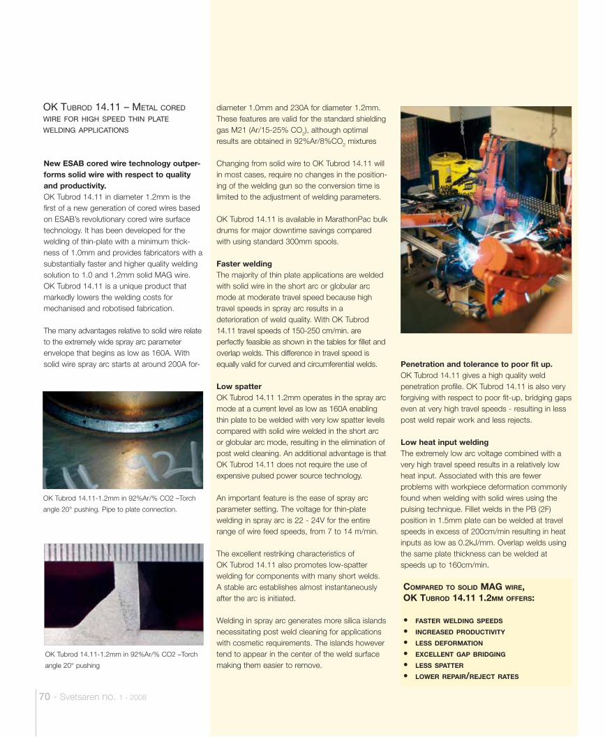
70 - Svetsaren no. 1 - 2008
OK Tubrod 14.11-1.2mm in 92%Ar/% CO2 –Torch
angle 20° pushing
New ESAB cored wire technology outper-forms solid wire with respect to quality and productivity.OK Tubrod 14.11 in diameter 1.2mm is the first of a new generation of cored wires based on ESAB’s revolutionary cored wire surface technology. It has been developed for the welding of thin-plate with a minimum thick-ness of 1.0mm and provides fabricators with a substantially faster and higher quality welding solution to 1.0 and 1.2mm solid MAG wire. OK Tubrod 14.11 is a unique product that markedly lowers the welding costs for mechanised and robotised fabrication.
The many advantages relative to solid wire relate to the extremely wide spray arc parameter envelope that begins as low as 160A. With solid wire spray arc starts at around 200A for-
OK TUBROD 14.11 – METAL CORED WIRE FOR HIGH SPEED THIN PLATE WELDING APPLICATIONS
COMPARED TO SOLID MAG WIRE, OK TUBROD 14.11 1.2MM OFFERS:
• FASTER WELDING SPEEDS
• INCREASED PRODUCTIVITY
• LESS DEFORMATION
• EXCELLENT GAP BRIDGING
• LESS SPATTER
• LOWER REPAIR/REJECT RATES
OK Tubrod 14.11-1.2mm in 92%Ar/% CO2 –Torch
angle 20° pushing. Pipe to plate connection.
diameter 1.0mm and 230A for diameter 1.2mm. These features are valid for the standard shielding gas M21 (Ar/15-25% CO2), although optimal results are obtained in 92%Ar/8%CO2 mixtures
Changing from solid wire to OK Tubrod 14.11 will in most cases, require no changes in the position-ing of the welding gun so the conversion time is limited to the adjustment of welding parameters.
OK Tubrod 14.11 is available in MarathonPac bulk drums for major downtime savings compared with using standard 300mm spools.
Faster weldingThe majority of thin plate applications are welded with solid wire in the short arc or globular arc mode at moderate travel speed because high travel speeds in spray arc results in a deterioration of weld quality. With OK Tubrod 14.11 travel speeds of 150-250 cm/min. are perfectly feasible as shown in the tables for fillet and overlap welds. This difference in travel speed is equally valid for curved and circumferential welds.
Low spatterOK Tubrod 14.11 1.2mm operates in the spray arc mode at a current level as low as 160A enabling thin plate to be welded with very low spatter levels compared with solid wire welded in the short arc or globular arc mode, resulting in the elimination of post weld cleaning. An additional advantage is that OK Tubrod 14.11 does not require the use of expensive pulsed power source technology.
An important feature is the ease of spray arc parameter setting. The voltage for thin-plate welding in spray arc is 22 - 24V for the entire range of wire feed speeds, from 7 to 14 m/min.
The excellent restriking characteristics of OK Tubrod 14.11 also promotes low-spatter welding for components with many short welds. A stable arc establishes almost instantaneously after the arc is initiated.
Welding in spray arc generates more silica islands necessitating post weld cleaning for applications with cosmetic requirements. The islands however tend to appear in the center of the weld surface making them easier to remove.
Penetration and tolerance to poor fit up.OK Tubrod 14.11 gives a high quality weld penetration profile. OK Tubrod 14.11 is also very forgiving with respect to poor fit-up, bridging gaps even at very high travel speeds - resulting in less post weld repair work and less rejects.
Low heat input weldingThe extremely low arc voltage combined with a very high travel speed results in a relatively low heat input. Associated with this are fewer problems with workpiece deformation commonly found when welding with solid wires using the pulsing technique. Fillet welds in the PB (2F) position in 1.5mm plate can be welded at travel speeds in excess of 200cm/min resulting in heat inputs as low as 0.2kJ/mm. Overlap welds using the same plate thickness can be welded at speeds up to 160cm/min.
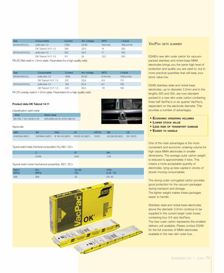
Svetsaren no. 1 - 2008 - 71
Gas Consumable Current Arc voltage WFS v travel
92%Ar/8%CO2 solid wire 1.0 218A 22.8V 10m/min 165cm/min
OK Tubrod 14.11 1.2 328 22.5 14 220
80%Ar/20%CO2 solid wire 1.0 220 24.5 11 155
OK Tubrod 14.11 1.2 311 24 12.5 200
PB (2F) fi llet weld in 1.5mm plate. Parameters for a high quality weld.
Product data OK Tubrod 14.11
Classifi cation weld metal
Wire Weld metal
EN 758: T 42 4 M M 3 H5 SFA/AWS A5.18: E70C-6M H4
Approvals
ABS BV DNV LR VdTÜV DB CE
4Y400SA (M21) S3YMHH (M21) III Y40 H5 (M21) 4Y40S H5 (M21) 10010 42.039.28 (M21) EN 13479
Typical weld metal chemical composition (%), M21, DC+
C Si Mn
0.048 0.64 1.45
Typical weld metal mechanical properties, M21, DC+
Rp0.2(MPa)
Rm(MPa)
A4-A5(%)
CVN(J at °C)
458 558 32 55/-40
Gas Consumable Current Arc voltage WFS v travel
92%Ar/8%CO2 solid wire 1.0 185A 20.3V 8.1m/min 105cm/min
OK Tubrod 14.11 1.2 237 23.8 8.5 170
80%Ar/20%CO2 solid wire 1.0 183 20.3 8.1 100
OK Tubrod 14.11 1.2 245 26.5 7.8 160
PA (1F) overlap weld in 1.5mm plate. Parameters for a high quality weld.
ESAB’s new slim outer carton for vacuum-packed stainless and nickel-base MMA electrodes brings you the same high level of protection and quality you are used to, but in more practical quantities that will keep your stock value low.
ESAB stainless steel and nickel-base electrodes, up to diameter 3.2mm and in the lengths 300 and 350, are now standard packed in a new slim outer carton containing three half VacPac’s or six quarter VacPac’s, dependent on the electrode diameter. This provides a number of advantages.
One of the main advantages is the more convenient and economic ordering volume for high value MMA electrodes in smaller dimensions. The average outer carton weight is reduced to approximately 4 kilos. This means a more acceptable quantity of electrodes, tying up less capital in stocks of slower moving consumables.
The strong outer corrugated carton provides good protection for the vacuum packages during transport and storage.The lighter weight makes these packages easier to handle.
Stainless steel and nickel-base electrodes above the diameter 3.2mm continue to be supplied in the current larger outer boxes containing four 3/4 size VacPacs.The new outer carton represents the smallest delivery unit available. Please contact ESAB for the full overview of MMA electrodes available in the new slim outer box.
VACPAC GETS SLIMMER
• ECONOMIC ORDERING VOLUMES
• LOWER STOCK VALUE
• LESS RISK OF TRANSPORT DAMAGE
• EASIER TO HANDLE

ESAB ABBox 8004 S-402 77 Gothenburg, Sweden
Tel. +46 31 50 90 00. Fax. +46 31 50 93 90www.esab.com
Related Documents