Technical Communication Finite element modeling of the consolidation behavior of multi-column supported road embankment Sari W. Abusharar, Jun-Jie Zheng * , Bao-Guo Chen Institute of Geotechnical and Underground Engineering, Huazhong University of Science and Technology, 1037 Luoyu Road, Hongshan District, Wuhan, Hubei Province 430074, China article info Article history: Received 29 February 2008 Received in revised form 22 September 2008 Accepted 23 September 2008 Available online 1 November 2008 Keywords: Multi-column FEM Settlement Consolidation analysis Elasto-plasticity Embankment abstract A multi-column composite foundation is a new concept utilizing different column types with varying lengths and diameters to support the embankment fill and to mobilize the strength and stiffness of the soil at shallow depths. This study presents the results of finite element analyses using the finite ele- ment software PLAXIS to investigate the consolidation behavior of a road embankment constructed on a multi-column composite foundation. The finite element results are calibrated for a period of 200 days. The settlement, horizontal displacement, differential settlement, column axial force, and the develop- ment and dissipation of excess pore pressure are presented and discussed in detail. It is concluded that a multi-column composite foundation allows a fast rate of consolidation and significantly increases the embankment stability. A multi-column composite foundation formed by CFG–lime columns is more effective than one formed by SC–lime columns. The CFG–lime columns improve the long-term stability of the embankment because the compression modulus of CFG columns is significantly greater than that of SC columns. Ó 2008 Elsevier Ltd. All rights reserved. 1. Introduction The construction of embankments overlying soft soil with a high groundwater level often leads to large lateral pressures and movement, excessive settlements as well as slope and bearing fail- ures, which usually result in long construction delays and costly remedial works. In such instances, ground improvement measures are often used to enhance stability and minimize ground move- ment. Examples of such soil improvement methods are preloading, vertical drains or grouting injection [1–3]. In China, combinations of cement–fly ash–gravel (CFG), soil–ce- ment (SC), and lime columns are often used as ground improve- ment measures to support highway embankments overlying soft soils. This system consists of installing different column types with different lengths and diameters to support the embankment fill and to mobilize the strength and stiffness of the soil at shallow depths. Fig. 1 shows an example of such a composite foundation, where the embankment is supported by long CFG columns or SC columns and shorter lime columns (also called chemico columns). The long columns are generally much stiffer than the short col- umns and they are used much like piles to mobilize the bearing capacity of the deeper soil strata. The more flexible lime columns strengthen and stiffen the shallower soil strata, thereby allowing the latter to be utilized as a load-supporting system. In many areas in China, this ground improvement method is being increasingly adopted. In recent years, a substantial amount of research has been con- ducted on such multi-column composite foundations. For instance, Liu et al. [4] and Chen et al. [5] performed field tests on composite foundation comprising two types of columns. Zhou et al. [6] carried out field tests on a composite foundation with three to four differ- ent column types. Chen [7] reported finite element analyses on multi-column composite foundation. Yan et al. [8] developed a sys- tematic design method for multi-column composite foundation while Zheng et al. [9] proposed a design methodology for CFG–lime column composite foundation, which is now being used exten- sively in China and has proven to be an economical way of control- ling settlements within the allowable levels and increasing the bearing capacity. Liang et al. [10] performed three-dimensional fi- nite element method analyses of a composite piled raft foundation with different pile types. Zheng et al. [11] reported three-dimen- sional finite element method analyses of a multi-element compos- ite foundation with SC–lime columns. Zheng et al. [12] conducted a series of three-dimensional finite element analyses on CFG–lime columns composite foundation with varying lengths and diame- ters. However, there are very few studies on multi-column com- posite foundations formed by CFG–lime columns or SC–lime columns at present. To the best of the authors’ knowledge, this is the first attempt to address the behavior of multi-column composite foundation for 0266-352X/$ - see front matter Ó 2008 Elsevier Ltd. All rights reserved. doi:10.1016/j.compgeo.2008.09.006 * Corresponding author. Tel.: +86 27 87557024; fax: +86 27 87542231. E-mail addresses: [email protected] (S.W. Abusharar), zhengjj@hust. edu.cn (J.-J. Zheng), [email protected] (B.-G. Chen). Computers and Geotechnics 36 (2009) 676–685 Contents lists available at ScienceDirect Computers and Geotechnics journal homepage: www.elsevier.com/locate/compgeo

Welcome message from author
This document is posted to help you gain knowledge. Please leave a comment to let me know what you think about it! Share it to your friends and learn new things together.
Transcript
Computers and Geotechnics 36 (2009) 676–685
Contents lists available at ScienceDirect
Computers and Geotechnics
journal homepage: www.elsevier .com/ locate/compgeo
Technical Communication
Finite element modeling of the consolidation behavior of multi-columnsupported road embankment
Sari W. Abusharar, Jun-Jie Zheng *, Bao-Guo ChenInstitute of Geotechnical and Underground Engineering, Huazhong University of Science and Technology, 1037 Luoyu Road, Hongshan District, Wuhan, Hubei Province 430074, China
a r t i c l e i n f o a b s t r a c t
Article history:Received 29 February 2008Received in revised form 22 September2008Accepted 23 September 2008Available online 1 November 2008
Keywords:Multi-columnFEMSettlementConsolidation analysisElasto-plasticityEmbankment
0266-352X/$ - see front matter � 2008 Elsevier Ltd.doi:10.1016/j.compgeo.2008.09.006
* Corresponding author. Tel.: +86 27 87557024; faxE-mail addresses: [email protected] (S.W
edu.cn (J.-J. Zheng), [email protected] (B.-G. Che
A multi-column composite foundation is a new concept utilizing different column types with varyinglengths and diameters to support the embankment fill and to mobilize the strength and stiffness ofthe soil at shallow depths. This study presents the results of finite element analyses using the finite ele-ment software PLAXIS to investigate the consolidation behavior of a road embankment constructed on amulti-column composite foundation. The finite element results are calibrated for a period of 200 days.The settlement, horizontal displacement, differential settlement, column axial force, and the develop-ment and dissipation of excess pore pressure are presented and discussed in detail. It is concluded thata multi-column composite foundation allows a fast rate of consolidation and significantly increases theembankment stability. A multi-column composite foundation formed by CFG–lime columns is moreeffective than one formed by SC–lime columns. The CFG–lime columns improve the long-term stabilityof the embankment because the compression modulus of CFG columns is significantly greater than thatof SC columns.
� 2008 Elsevier Ltd. All rights reserved.
1. Introduction
The construction of embankments overlying soft soil with ahigh groundwater level often leads to large lateral pressures andmovement, excessive settlements as well as slope and bearing fail-ures, which usually result in long construction delays and costlyremedial works. In such instances, ground improvement measuresare often used to enhance stability and minimize ground move-ment. Examples of such soil improvement methods are preloading,vertical drains or grouting injection [1–3].
In China, combinations of cement–fly ash–gravel (CFG), soil–ce-ment (SC), and lime columns are often used as ground improve-ment measures to support highway embankments overlying softsoils. This system consists of installing different column types withdifferent lengths and diameters to support the embankment filland to mobilize the strength and stiffness of the soil at shallowdepths. Fig. 1 shows an example of such a composite foundation,where the embankment is supported by long CFG columns or SCcolumns and shorter lime columns (also called chemico columns).The long columns are generally much stiffer than the short col-umns and they are used much like piles to mobilize the bearingcapacity of the deeper soil strata. The more flexible lime columnsstrengthen and stiffen the shallower soil strata, thereby allowing
All rights reserved.
: +86 27 87542231.. Abusharar), [email protected]).
the latter to be utilized as a load-supporting system. In many areasin China, this ground improvement method is being increasinglyadopted.
In recent years, a substantial amount of research has been con-ducted on such multi-column composite foundations. For instance,Liu et al. [4] and Chen et al. [5] performed field tests on compositefoundation comprising two types of columns. Zhou et al. [6] carriedout field tests on a composite foundation with three to four differ-ent column types. Chen [7] reported finite element analyses onmulti-column composite foundation. Yan et al. [8] developed a sys-tematic design method for multi-column composite foundationwhile Zheng et al. [9] proposed a design methodology for CFG–limecolumn composite foundation, which is now being used exten-sively in China and has proven to be an economical way of control-ling settlements within the allowable levels and increasing thebearing capacity. Liang et al. [10] performed three-dimensional fi-nite element method analyses of a composite piled raft foundationwith different pile types. Zheng et al. [11] reported three-dimen-sional finite element method analyses of a multi-element compos-ite foundation with SC–lime columns. Zheng et al. [12] conducted aseries of three-dimensional finite element analyses on CFG–limecolumns composite foundation with varying lengths and diame-ters. However, there are very few studies on multi-column com-posite foundations formed by CFG–lime columns or SC–limecolumns at present.
To the best of the authors’ knowledge, this is the first attempt toaddress the behavior of multi-column composite foundation for
EmbankmentReinforcement
(Optional)
Soft soil
Firm soil or bedrock
Long columns
Short columns
Fig. 1. A multi-column supported embankment.
S.W. Abusharar et al. / Computers and Geotechnics 36 (2009) 676–685 677
supporting embankment fill. Numerical analyses considering real-istic parameters are particularly needed for better utilization of thetechnique. This paper presents the results of a series of two-dimen-sional (2D) finite element analyses of the consolidation behavior ofa multi-column supported embankment using the finite elementsoftware PLAXIS. Parametric studies are presented that shed lighton effective combinations of columns.
2. Plane strain finite element analysis
2.1. Problem dimensions
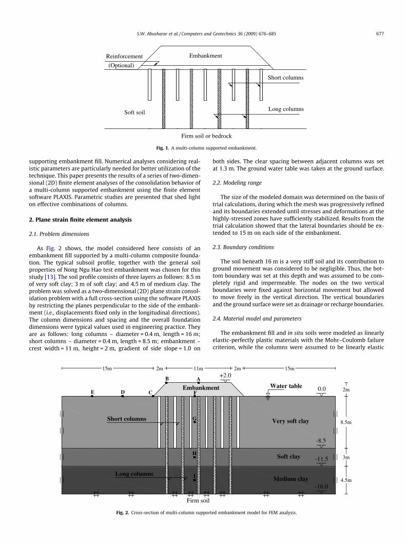
As Fig. 2 shows, the model considered here consists of anembankment fill supported by a multi-column composite founda-tion. The typical subsoil profile, together with the general soilproperties of Nong Ngu Hao test embankment was chosen for thisstudy [13]. The soil profile consists of three layers as follows: 8.5 mof very soft clay; 3 m of soft clay; and 4.5 m of medium clay. Theproblem was solved as a two-dimensional (2D) plane strain consol-idation problem with a full cross-section using the software PLAXISby restricting the planes perpendicular to the side of the embank-ment (i.e., displacements fixed only in the longitudinal directions).The column dimensions and spacing and the overall foundationdimensions were typical values used in engineering practice. Theyare as follows: long columns – diameter = 0.4 m, length = 16 m;short columns – diameter = 0.4 m, length = 8.5 m; embankment –crest width = 11 m, height = 2 m, gradient of side slope = 1.0 on
15m 2m 11m
Firm soil
AB
C F
Short columns
Long columns
EmbankmDE
G
H
I
Fig. 2. Cross-section of multi-column support
both sides. The clear spacing between adjacent columns was setat 1.3 m. The ground water table was taken at the ground surface.
2.2. Modeling range
The size of the modeled domain was determined on the basis oftrial calculations, during which the mesh was progressively refinedand its boundaries extended until stresses and deformations at thehighly-stressed zones have sufficiently stabilized. Results from thetrial calculation showed that the lateral boundaries should be ex-tended to 15 m on each side of the embankment.
2.3. Boundary conditions
The soil beneath 16 m is a very stiff soil and its contribution toground movement was considered to be negligible. Thus, the bot-tom boundary was set at this depth and was assumed to be com-pletely rigid and impermeable. The nodes on the two verticalboundaries were fixed against horizontal movement but allowedto move freely in the vertical direction. The vertical boundariesand the ground surface were set as drainage or recharge boundaries.
2.4. Material model and parameters
The embankment fill and in situ soils were modeled as linearlyelastic-perfectly plastic materials with the Mohr–Coulomb failurecriterion, while the columns were assumed to be linearly elastic
2m 15m
8.5m
3m
4.5m
2m
Very soft clay
Soft clay
Medium clay
ent Water table 0.0
-8.5
-11.5
-16.0
+2.0
ed embankment model for FEM analysis.
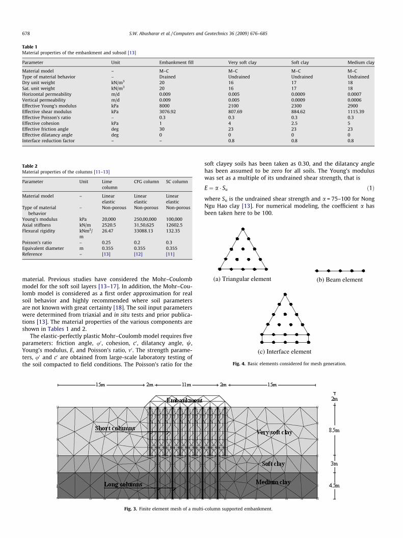
Table 1Material properties of the embankment and subsoil [13]
Parameter Unit Embankment fill Very soft clay Soft clay Medium clay
Material model – M–C M–C M–C M–CType of material behavior – Drained Undrained Undrained UndrainedDry unit weight kN/m3 20 16 17 18Sat. unit weight kN/m3 20 16 17 18Horizontal permeability m/d 0.009 0.005 0.0009 0.0007Vertical permeability m/d 0.009 0.005 0.0009 0.0006Effective Young’s modulus kPa 8000 2100 2300 2900Effective shear modulus kPa 3076.92 807.69 884.62 1115.39Effective Poisson’s ratio – 0.3 0.3 0.3 0.3Effective cohesion kPa 1 4 2.5 5Effective friction angle deg 30 23 23 23Effective dilatancy angle deg 0 0 0 0Interface reduction factor – – 0.8 0.8 0.8
Table 2Material properties of the columns [11–13]
Parameter Unit Limecolumn
CFG column SC column
Material model – Linearelastic
Linearelastic
Linearelastic
Type of materialbehavior
– Non-porous Non-porous Non-porous
Young’s modulus kPa 20,000 250,00,000 100,000Axial stiffness kN/m 2520.5 31,50,625 12602.5Flexural rigidity kNm2/
m26.47 33088.13 132.35
Poisson’s ratio – 0.25 0.2 0.3Equivalent diameter m 0.355 0.355 0.355Reference – [13] [12] [11]
(a) Triangular element
(c) Interface element
(b) Beam element
Fig. 4. Basic elements considered for mesh generation.
678 S.W. Abusharar et al. / Computers and Geotechnics 36 (2009) 676–685
material. Previous studies have considered the Mohr–Coulombmodel for the soft soil layers [13–17]. In addition, the Mohr–Cou-lomb model is considered as a first order approximation for realsoil behavior and highly recommended where soil parametersare not known with great certainty [18]. The soil input parameterswere determined from triaxial and in situ tests and prior publica-tions [13]. The material properties of the various components areshown in Tables 1 and 2.
The elastic-perfectly plastic Mohr–Coulomb model requires fiveparameters: friction angle, u0, cohesion, c0, dilatancy angle, w,Young’s modulus, E, and Poisson’s ratio, m0. The strength parame-ters, u0 and c0 are obtained from large-scale laboratory testing ofthe soil compacted to field conditions. The Poisson’s ratio for the
Fig. 3. Finite element mesh of a multi
soft clayey soils has been taken as 0.30, and the dilatancy anglehas been assumed to be zero for all soils. The Young’s moduluswas set as a multiple of its undrained shear strength, that is
E ¼ a � Su ð1Þ
where Su is the undrained shear strength and a = 75–100 for NongNgu Hao clay [13]. For numerical modeling, the coefficient a hasbeen taken here to be 100.
-column supported embankment.
S.W. Abusharar et al. / Computers and Geotechnics 36 (2009) 676–685 679
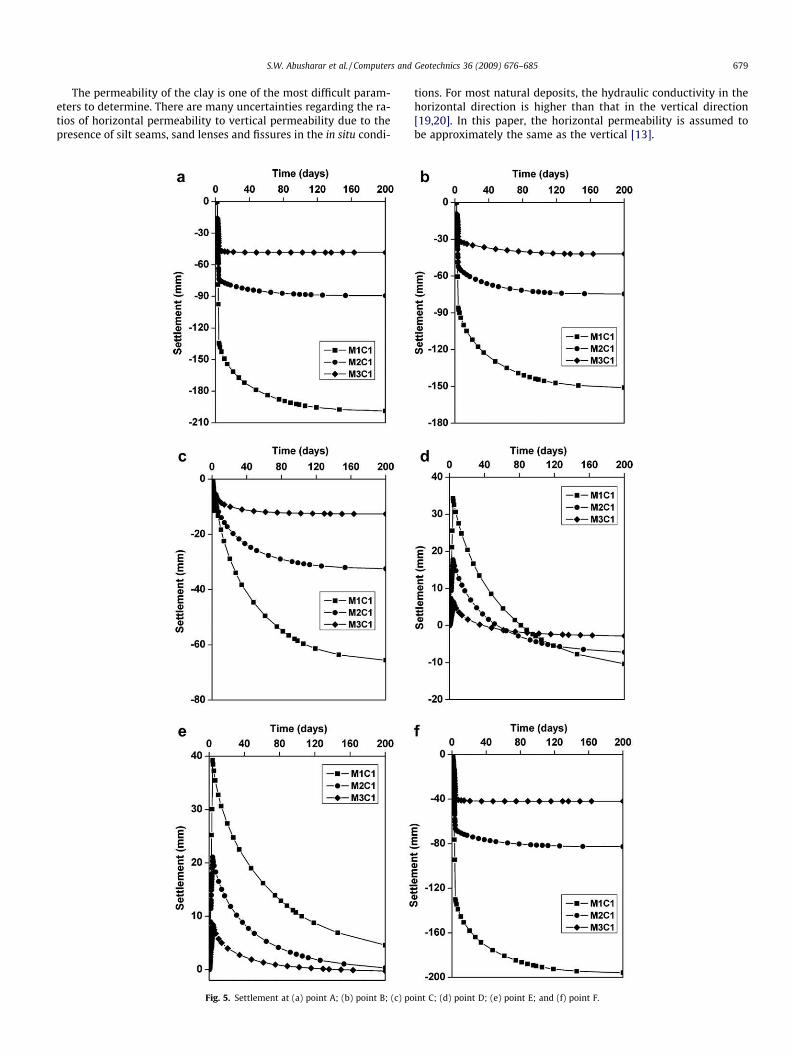
The permeability of the clay is one of the most difficult param-eters to determine. There are many uncertainties regarding the ra-tios of horizontal permeability to vertical permeability due to thepresence of silt seams, sand lenses and fissures in the in situ condi-
Fig. 5. Settlement at (a) point A; (b) point B; (c) po
tions. For most natural deposits, the hydraulic conductivity in thehorizontal direction is higher than that in the vertical direction[19,20]. In this paper, the horizontal permeability is assumed tobe approximately the same as the vertical [13].
int C; (d) point D; (e) point E; and (f) point F.
680 S.W. Abusharar et al. / Computers and Geotechnics 36 (2009) 676–685
2.5. Mesh generation
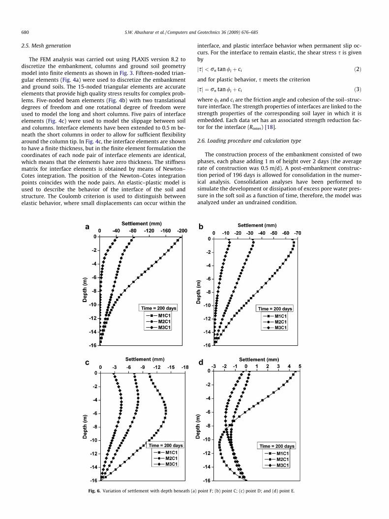
The FEM analysis was carried out using PLAXIS version 8.2 todiscretize the embankment, columns and ground soil geometrymodel into finite elements as shown in Fig. 3. Fifteen-noded trian-gular elements (Fig. 4a) were used to discretize the embankmentand ground soils. The 15-noded triangular elements are accurateelements that provide high quality stress results for complex prob-lems. Five-noded beam elements (Fig. 4b) with two translationaldegrees of freedom and one rotational degree of freedom wereused to model the long and short columns. Five pairs of interfaceelements (Fig. 4c) were used to model the slippage between soiland columns. Interface elements have been extended to 0.5 m be-neath the short columns in order to allow for sufficient flexibilityaround the column tip. In Fig. 4c, the interface elements are shownto have a finite thickness, but in the finite element formulation thecoordinates of each node pair of interface elements are identical,which means that the elements have zero thickness. The stiffnessmatrix for interface elements is obtained by means of Newton–Cotes integration. The position of the Newton–Cotes integrationpoints coincides with the node pairs. An elastic–plastic model isused to describe the behavior of the interface of the soil andstructure. The Coulomb criterion is used to distinguish betweenelastic behavior, where small displacements can occur within the
Fig. 6. Variation of settlement with depth beneath (a)
interface, and plastic interface behavior when permanent slip oc-curs. For the interface to remain elastic, the shear stress s is givenby
jsj < rn tan /i þ ci ð2Þ
and for plastic behavior, s meets the criterion
jsj ¼ rn tan /i þ ci ð3Þ
where /i and ci are the friction angle and cohesion of the soil–struc-ture interface. The strength properties of interfaces are linked to thestrength properties of the corresponding soil layer in which it isembedded. Each data set has an associated strength reduction fac-tor for the interface (Rinter) [18].
2.6. Loading procedure and calculation type
The construction process of the embankment consisted of twophases, each phase adding 1 m of height over 2 days (the averagerate of construction was 0.5 m/d). A post-embankment construc-tion period of 196 days is allowed for consolidation in the numer-ical analysis. Consolidation analyses have been performed tosimulate the development or dissipation of excess pore water pres-sure in the soft soil as a function of time, therefore, the model wasanalyzed under an undrained condition.
point F; (b) point C; (c) point D; and (d) point E.
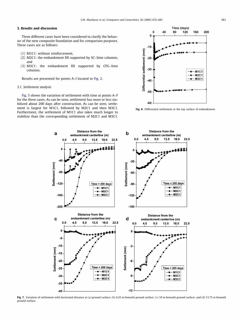
Fig. 8. Differential settlement at the top surface of embankment.
S.W. Abusharar et al. / Computers and Geotechnics 36 (2009) 676–685 681
3. Results and discussion
Three different cases have been considered to clarify the behav-ior of the new composite foundation and for comparison purposes.These cases are as follows:
(1) M1C1: without reinforcement,(2) M2C1: the embankment fill supported by SC–lime columns,
and(3) M3C1: the embankment fill supported by CFG–lime
columns.
Results are presented for points A–I located in Fig. 2.
3.1. Settlement analysis
Fig. 5 shows the variation of settlement with time at points A–Ffor the three cases. As can be seen, settlement has more or less sta-bilized about 200 days after construction. As can be seen, settle-ment is largest for M1C1, followed by M2C1 and then M3C1.Furthermore, the settlement of M1C1 also takes much longer tostabilize than the corresponding settlement of M2C1 and M3C1.
Fig. 7. Variation of settlement with horizontal distance at (a) ground surface; (b) 4.25 m beneath ground surface; (c) 10 m beneath ground surface; and (d) 13.75 m beneathground surface.
682 S.W. Abusharar et al. / Computers and Geotechnics 36 (2009) 676–685
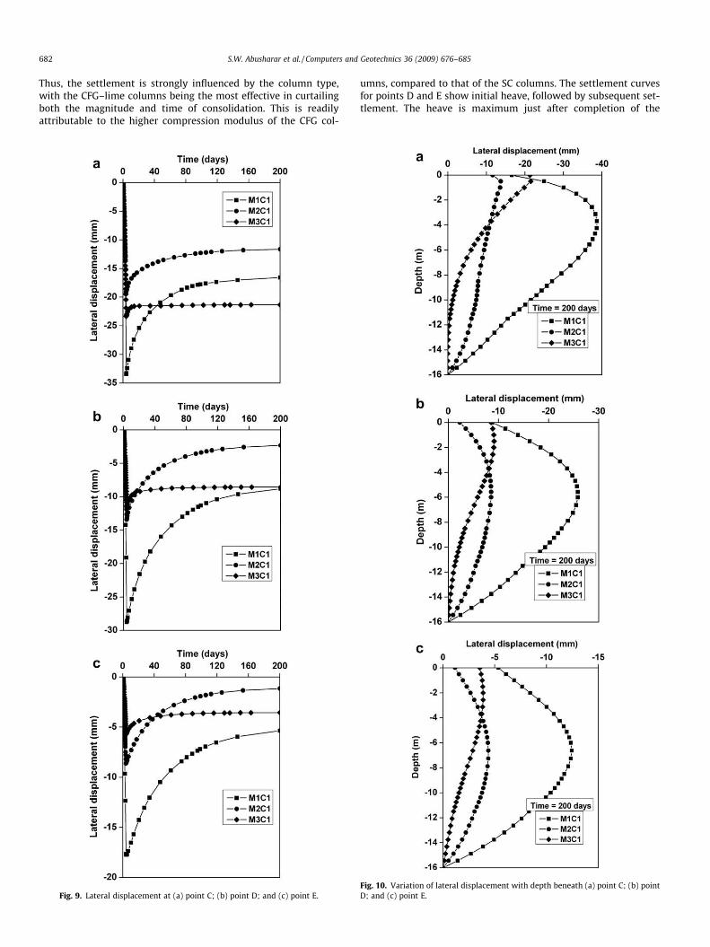
Thus, the settlement is strongly influenced by the column type,with the CFG–lime columns being the most effective in curtailingboth the magnitude and time of consolidation. This is readilyattributable to the higher compression modulus of the CFG col-
Fig. 9. Lateral displacement at (a) point C; (b) point D; and (c) point E.
umns, compared to that of the SC columns. The settlement curvesfor points D and E show initial heave, followed by subsequent set-tlement. The heave is maximum just after completion of the
Fig. 10. Variation of lateral displacement with depth beneath (a) point C; (b) pointD; and (c) point E.
S.W. Abusharar et al. / Computers and Geotechnics 36 (2009) 676–685 683
embankment. Once again, case M1C1 shows the largest groundmovement, followed by M2C1 and finally M3C1.
Fig. 6 shows the variation of settlement with depth beneathpoints C–F. As shown in Fig. 6, the settlement decreases mono-tonically with depth beneath points F and C, while the settlementbeneath point D increases first then decreases with depth. It canbe seen in Fig. 6d that the upper part of the soil beneath point Eis heaving whereas the lower part is settling. It can also be seenthat the maximum settlement occurs at the ground surface atpoint F.
Fig. 7 shows the variation of settlement along the base of theembankment at the ground surface, 4.25 m beneath ground surface(at the middle of very soft clay layer), 10 m beneath ground surface(at the middle of soft clay layer), and 13.75 m beneath ground sur-face (at the middle of medium clay layer). The settlement profileshows that the maximum settlement occurs at the middle and atthe ground surface and keeps decreasing towards the toe of theembankment and with depth. It can also be seen that surface heavestarts at a distance 10 m outside the embankment and continuesincreasing. Moreover, the maximum heave occurs at the groundsurface and decreases with depth. The differential settlement be-tween the columns and surrounding subsoil arising from the dif-ferences in stiffness is also evident in Fig. 8. This differentialsettlement also decreases with depth as settlement decreases.
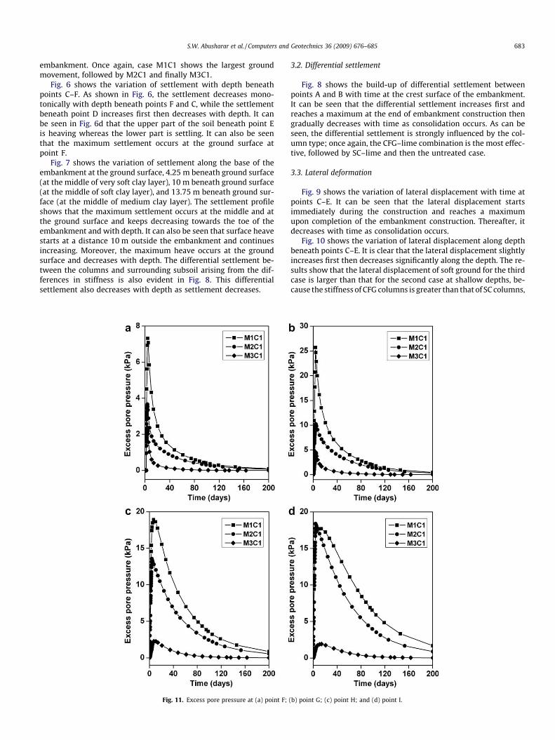
Fig. 11. Excess pore pressure at (a) point F;
3.2. Differential settlement
Fig. 8 shows the build-up of differential settlement betweenpoints A and B with time at the crest surface of the embankment.It can be seen that the differential settlement increases first andreaches a maximum at the end of embankment construction thengradually decreases with time as consolidation occurs. As can beseen, the differential settlement is strongly influenced by the col-umn type; once again, the CFG–lime combination is the most effec-tive, followed by SC–lime and then the untreated case.
3.3. Lateral deformation
Fig. 9 shows the variation of lateral displacement with time atpoints C–E. It can be seen that the lateral displacement startsimmediately during the construction and reaches a maximumupon completion of the embankment construction. Thereafter, itdecreases with time as consolidation occurs.
Fig. 10 shows the variation of lateral displacement along depthbeneath points C–E. It is clear that the lateral displacement slightlyincreases first then decreases significantly along the depth. The re-sults show that the lateral displacement of soft ground for the thirdcase is larger than that for the second case at shallow depths, be-cause the stiffness of CFG columns is greater than that of SC columns,
(b) point G; (c) point H; and (d) point I.
684 S.W. Abusharar et al. / Computers and Geotechnics 36 (2009) 676–685
while at larger depths, the lateral displacement of the soft ground forthe third case is smaller than that for the second case. It is also clearthat multi-column ground treatments are effective in reducing thelateral displacement of the composite foundation along depth.
3.4. Excess pore pressure analysis
In this study, it is assumed that the excess pore water pressureinduced by the installation of columns has dissipated before theconstruction of the embankment over the soft ground. An embank-ment construction period of 200 days is allowed for consolidationin the numerical analysis. Fig. 11 shows the variation of excesspore pressure with time at points F–I. It is clearly shown that dis-sipation starts immediately during the construction and continuesafterwards. The rate of dissipation reaches a maximum once theembankment construction is completed and then decreases withtime. It is also clear that the excess pore pressure increases withthe depth from the ground surface.
3.5. Axial forces of columns
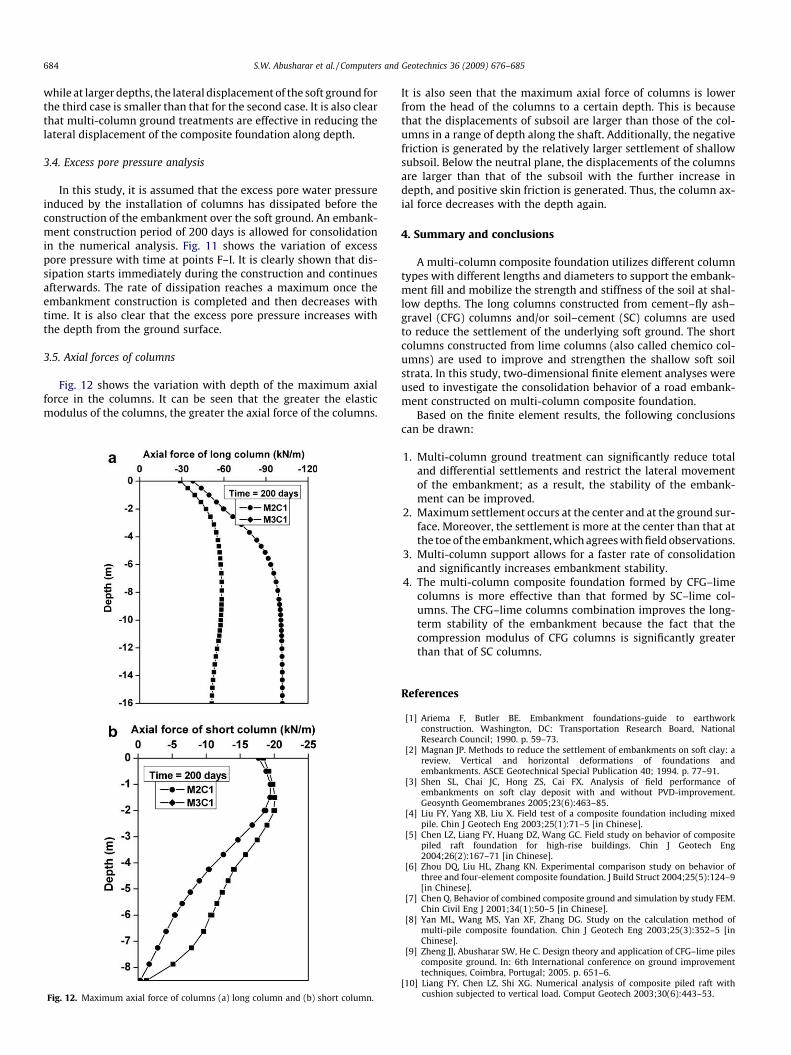
Fig. 12 shows the variation with depth of the maximum axialforce in the columns. It can be seen that the greater the elasticmodulus of the columns, the greater the axial force of the columns.
Fig. 12. Maximum axial force of columns (a) long column and (b) short column.
It is also seen that the maximum axial force of columns is lowerfrom the head of the columns to a certain depth. This is becausethat the displacements of subsoil are larger than those of the col-umns in a range of depth along the shaft. Additionally, the negativefriction is generated by the relatively larger settlement of shallowsubsoil. Below the neutral plane, the displacements of the columnsare larger than that of the subsoil with the further increase indepth, and positive skin friction is generated. Thus, the column ax-ial force decreases with the depth again.
4. Summary and conclusions
A multi-column composite foundation utilizes different columntypes with different lengths and diameters to support the embank-ment fill and mobilize the strength and stiffness of the soil at shal-low depths. The long columns constructed from cement–fly ash–gravel (CFG) columns and/or soil–cement (SC) columns are usedto reduce the settlement of the underlying soft ground. The shortcolumns constructed from lime columns (also called chemico col-umns) are used to improve and strengthen the shallow soft soilstrata. In this study, two-dimensional finite element analyses wereused to investigate the consolidation behavior of a road embank-ment constructed on multi-column composite foundation.
Based on the finite element results, the following conclusionscan be drawn:
1. Multi-column ground treatment can significantly reduce totaland differential settlements and restrict the lateral movementof the embankment; as a result, the stability of the embank-ment can be improved.
2. Maximum settlement occurs at the center and at the ground sur-face. Moreover, the settlement is more at the center than that atthe toe of the embankment, which agrees with field observations.
3. Multi-column support allows for a faster rate of consolidationand significantly increases embankment stability.
4. The multi-column composite foundation formed by CFG–limecolumns is more effective than that formed by SC–lime col-umns. The CFG–lime columns combination improves the long-term stability of the embankment because the fact that thecompression modulus of CFG columns is significantly greaterthan that of SC columns.
References
[1] Ariema F, Butler BE. Embankment foundations-guide to earthworkconstruction. Washington, DC: Transportation Research Board, NationalResearch Council; 1990. p. 59–73.
[2] Magnan JP. Methods to reduce the settlement of embankments on soft clay: areview. Vertical and horizontal deformations of foundations andembankments. ASCE Geotechnical Special Publication 40; 1994. p. 77–91.
[3] Shen SL, Chai JC, Hong ZS, Cai FX. Analysis of field performance ofembankments on soft clay deposit with and without PVD-improvement.Geosynth Geomembranes 2005;23(6):463–85.
[4] Liu FY, Yang XB, Liu X. Field test of a composite foundation including mixedpile. Chin J Geotech Eng 2003;25(1):71–5 [in Chinese].
[5] Chen LZ, Liang FY, Huang DZ, Wang GC. Field study on behavior of compositepiled raft foundation for high-rise buildings. Chin J Geotech Eng2004;26(2):167–71 [in Chinese].
[6] Zhou DQ, Liu HL, Zhang KN. Experimental comparison study on behavior ofthree and four-element composite foundation. J Build Struct 2004;25(5):124–9[in Chinese].
[7] Chen Q. Behavior of combined composite ground and simulation by study FEM.Chin Civil Eng J 2001;34(1):50–5 [in Chinese].
[8] Yan ML, Wang MS, Yan XF, Zhang DG. Study on the calculation method ofmulti-pile composite foundation. Chin J Geotech Eng 2003;25(3):352–5 [inChinese].
[9] Zheng JJ, Abusharar SW, He C. Design theory and application of CFG–lime pilescomposite ground. In: 6th International conference on ground improvementtechniques, Coimbra, Portugal; 2005. p. 651–6.
[10] Liang FY, Chen LZ, Shi XG. Numerical analysis of composite piled raft withcushion subjected to vertical load. Comput Geotech 2003;30(6):443–53.

S.W. Abusharar et al. / Computers and Geotechnics 36 (2009) 676–685 685
[11] Zheng JJ, Ou JH, Wang XZ. Three-dimensional finite element analysis of multi-element composite foundation. In: The 9th international conference onenhancement and promotion of computational methods in engineering andscience, Macao; 2003.
[12] Zheng JJ, Abusharar SW, Wang XZ. Three-dimensional nonlinear finite elementmodeling of composite foundation formed by CFG–lime piles. Comput Geotech2008;35(4):637–43.
[13] Hossain MS, Haque MA, Rao KN. Embankment over soft soil improved withchemico pile – a numerical study. Advances in earth structures: research topractice (GSP 151). ASCE; 2006.
[14] Huang J, Han J, Porbaha A. Two and three-dimensional modeling of DMcolumns under embankments. GeoCongress. ASCE; 2006.
[15] Madhyannapu RS, Puppala AJ, Hossain S, Han J, Porbaha A. Analysis ofgeotextile reinforced embankment over deep mixed columns: using numericaland analytical tools. GeoCongress. ASCE; 2006.
[16] Han J, Huang J, Porbaha A. 2D numerical modeling of a constructedgeosynthetic-reinforced embankment over deep mixed columns.Contemporary issues in foundation engineering (GSP 131). ASCE; 2005.
[17] Chen RP, Chen YM, Xu ZZ. Interaction of rigid pile-supported embankment onsoft soil. Advances in earth structures: research to practice (GSP 131). ASCE;2006. p. 231–8.
[18] PLAXIS 2D V8. Reference manual; 2002.[19] Bergado DT, Enriquez AS, Sampaco CL, Alfaro MC. Inverse analysis of
geotechnical parameters on improved soft Bangkok clay. ASCE J Geotech Eng1990;18(7):1012–30.
[20] Hansbo S. Design aspects of vertical drains and lime column installations. In:Proceedings of 9th southeast Asian geotechnical conference, vol. 2. Bangkok;1987. p. 8-1–12.
Related Documents