List of Contents Abstract 1 1. Background 2 2. Microcontroller 9 2.1 Introduction 9 2.2 History 9 2.3 Definition of a Microcontroller 11 2.4 Microcontrollers vs Microprocessors 12 2.5 Memory Unit 13 2.6 Central Processing Unit 14 2.7 Bus 15 2.8 Input Output Unit 16 2.9 Serial Communication 16 2.10 Timer Unit 17 2.11 Watch Dog 18 2.12 Analog to Digital Converter 19 3. Introduction to EEPROM 21

Electronics Voting Machine
Oct 27, 2015
ABSTRACT
India is world’s largest democracy. It is perceived to be charismatic one as it accommodates cultural, regional, economical, social disparities and still is able to stand on its own. Fundamental right to vote or simply voting in elections forms the basis of Indian democracy.
In India all earlier elections be it state elections or centre elections a voter used to cast his/her vote to his/her favorite candidate by putting the stamp against his/her name and then folding the ballot paper as per a prescribed method before putting it in the Ballot box. This is a long, time-consuming process and very much prone to errors.
This situation continued till election scene was completely changed by electronic voting machine. No more ballot paper, ballot boxes, stamping, etc. all this condensed into a simple box called ballot unit of the electronic voting machine.
EVM is capable of saving considerable printing stationery and transport of large volumes of electoral material. It is easy to transport, store, and maintain. It completely rules out the chance of invalid votes. Its use results in reduction of polling time, resulting in fewer problems in electoral preparations, law and order, candidates' expenditure, etc. and easy and accurate counting without any mischief at the counting centre. It is also eco friendly.
Our EVM consists mainly of two units - (a) Control Unit (CU) and (b) Ballot Unit (BU) with cable for connecting it with Control unit. Both the units consists of one microcontroller (8052) each. The CU consists of one LCD, one hex keypad and a couple of switches, while BU consists of a candidate panel, a votecast panel and a buzzer, etc.
This project is based on assembly language programming. The software platform used in this project are Keil uVision3 and SPIPGM37.
1. BACKGROUND
Democracy And Voting
Democracy has come to be accepted as the most preferred form of political system all over the world. However, the success of a democratic structure is to be judged by the successes that can be solely attributed to this system. There are various challenges before democracy. These are foundational challenges, challenge of expansion and deepening of democracy. All of these are dependent on how the democracy is perceived by people who form the government, participate in formation of government and are benefited by it.
As we all know that India is world’s largest democracy. It is perceived to be charismatic one as it accommodates cultural, regional, economical, social disparities and still is able to stand on its own. India follows a federal form of government. It means that governance power is not residing with one authority, but is distributed at various levels. In India power is distributed between states and central authority.
What forms the basis of such vast and complex system of governance?
One needs not to be an Einstein to guess the answer. It is fundamental right to vote or simply voting in elections.
Indian constitution provide every adult above the age of 18 years irrespective of his/her religion, region, caste, creed, color, economic status, education and sex the essential right to vote and elect her/his candidate to represent her/him.
Hence voting can be termed as backbone of not just democracy in India but all around the world. Voting can be done in various ways. In early Roman Empire voting used to be done by raising hands in favor or against. In board rooms voting is done in similar way, some write their vote down, some choose to speak, some choose to cast vote using latest technology.
Voting Techniques
In India all earlier elections be it state elections or centre elections a voter used to cast his/her vote to his/her favorite candidate by putting the stamp against his/her name and then folding the ballot paper as per a prescribed method before putting it in the Ballot box. This is a long, time-consumin
Welcome message from author
This document is posted to help you gain knowledge. Please leave a comment to let me know what you think about it! Share it to your friends and learn new things together.
Transcript
List of Contents
Abstract 11. Background 22. Microcontroller 9
2.1 Introduction 9 2.2 History 92.3 Definition of a Microcontroller 112.4 Microcontrollers vs Microprocessors 122.5 Memory Unit 132.6 Central Processing Unit 142.7 Bus 152.8 Input Output Unit 162.9 Serial Communication 162.10 Timer Unit 172.11 Watch Dog 182.12 Analog to Digital Converter 19
3. Introduction to EEPROM 213.1 EEPROM 213.2 Application/ Operation of EEPROM 21
4. Introduction to 16X2 LCD Display 234.1 Pin description 234.2 DDRAM - Display Data RAM 244.3 BF - Busy Flag 244.4 Instruction Register (IR) and Data Register (DR) 244.5 Commands and Instruction set 244.6 Sending Commands to LCD 24
5. Introduction to I2C Bus 265.1 Basic Definition 265.2 Inside the box 265.3 Communication 275.4 A simple bus 285.5 The elegance of I2C 28
6. Project Description 306.1 Ballot unit 31
6.1(a) Block diagram 316.1(b) General working 316.1(c) Flowchart 32
6.1(d) Assembly language code 346.2 Control unit 37
6.2(a) Block diagram 376.2(b) General working 376.2(c) Flowchart 406.2(d) Assembly language code 47
7. Project Methodology 727.1 Components 72
7.1(a) Ballot unit 727.1(b) Control unit 73
7.2 Softwares used 747.3 Equipments used 747.4 Procedure of building the EVM 747.5 Using the Electronic Voting Machine 757.6 Hardware schematic 78
7.6(a) Ballot unit 787.6(b) Control unit 797.6(c) Complete EVM system 80
8. Result and Conclusion 819. Applications 8210. Future Scope 8311. References and Bibliography 84Appendix
1
ABSTRACT
India is world’s largest democracy. It is perceived to be charismatic one as it accommodates cultural, regional, economical, social disparities and still is able to stand on its own. Fundamental right to vote or simply voting in elections forms the basis of Indian democracy.
In India all earlier elections be it state elections or centre elections a voter used to cast his/her vote to his/her favorite candidate by putting the stamp against his/her name and then folding the ballot paper as per a prescribed method before putting it in the Ballot box. This is a long, time-consuming process and very much prone to errors.
This situation continued till election scene was completely changed by electronic voting machine. No more ballot paper, ballot boxes, stamping, etc. all this condensed into a simple box called ballot unit of the electronic voting machine.
EVM is capable of saving considerable printing stationery and transport of large volumes of electoral material. It is easy to transport, store, and maintain. It completely rules out the chance of invalid votes. Its use results in reduction of polling time, resulting in fewer problems in electoral preparations, law and order, candidates' expenditure, etc. and easy and accurate counting without any mischief at the counting centre. It is also eco friendly.
Our EVM consists mainly of two units - (a) Control Unit (CU) and (b) Ballot Unit (BU) with cable for connecting it with Control unit. Both the units consists of one microcontroller (8052) each. The CU consists of one LCD, one hex keypad and a couple of switches, while BU consists of a candidate panel, a votecast panel and a buzzer, etc.
This project is based on assembly language programming. The software platform used in this project are Keil uVision3 and SPIPGM37.
2

1. BACKGROUND
Democracy And Voting
Democracy has come to be accepted as the most preferred form of political system all over the world. However, the success of a democratic structure is to be judged by the successes that can be solely attributed to this system. There are various challenges before democracy. These are foundational challenges, challenge of expansion and deepening of democracy. All of these are dependent on how the democracy is perceived by people who form the government, participate in formation of government and are benefited by it.
As we all know that India is world’s largest democracy. It is perceived to be charismatic one as it accommodates cultural, regional, economical, social disparities and still is able to stand on its own. India follows a federal form of government. It means that governance power is not residing with one authority, but is distributed at various levels. In India power is distributed between states and central authority.
What forms the basis of such vast and complex system of governance?One needs not to be an Einstein to guess the answer. It is fundamental right to vote or simply voting in elections. Indian constitution provide every adult above the age of 18 years irrespective of his/her religion, region, caste, creed, color, economic status, education and sex the essential right to vote and elect her/his candidate to represent her/him.
Hence voting can be termed as backbone of not just democracy in India but all around the world. Voting can be done in various ways. In early Roman Empire voting used to be done by raising hands in favor or against. In board rooms voting is done in similar way, some write their vote down, some choose to speak, some choose to cast vote using latest technology.
Voting Techniques
In India all earlier elections be it state elections or centre elections a voter used to cast his/her vote to his/her favorite candidate by putting the stamp against his/her name and then folding the ballot paper as per a prescribed method before putting it in the Ballot box. This is a long, time-consuming process and very much prone to errors.
3
This method wanted voters to be skilled voters to know how to put a stamp, and methodical folding of ballot paper. Millions of paper would be printed and heavy ballot boxes would be loaded and unloaded to and from ballot office to polling station. All this continued till election scene was completely changed by electronic voting machine. No more ballot paper, ballot boxes, stamping, etc. all this condensed into a simple box called ballot unit of the electronic voting machine.
The marking system of voting was introduced in 1962 to make it possible for a substantial number of illiterate voters to indicate easily their preferences in choosing their representatives. Over the years, there was a pronounced increase in the volume of work: crores of ballot papers had to be printed and lakhs of ballot boxes had to be prepared, transported, and kept in storage; and a great amount of time was taken up by the conduct of elections. To overcome these difficulties, the Election Commission of India (ECI) thought of electronic gadgets. The Electronics Corporation of India Ltd. (ECIL), Hyderabad, and Bharat Electronics Ltd. (BEL), Bangalore, developed the electronic voting machine in 1981.
The Electronic Voting Machine
The complete EVM consists mainly of two units - (a) Control Unit and (b) Balloting Unit with cable for connecting it with Control unit. A Balloting Unit caters upto 16 candidates. Four Balloting Units linked together catering in all to 64 candidates can be used with one control unit. The control unit is kept with the Presiding Officer and the Balloting Unit is used by the voter for polling.
The Balloting Unit of EVM is a small Box-like device, on top of which each candidate and his/her election symbol is listed like a big ballot paper. Against each candidate's name, a red LED and a blue button is provided. The voter polls his vote by pressing the blue button against the name of his desired candidate.
How the Vote is cast with this EVM?
The entire process is very easy to understand: Like in earlier system, your name is called and you are asked to sign or put your
thumb impression in a register. After your identification is done by Election Officer, an ink mark is put on your
finger, same as earlier. Then the Election Officer gives you a slip that bears the Voter register number
where you signed or put your thumb impression. You hand over this slip to the presiding officer who confirms the serial number
and permits you to vote by pressing the button of the Control Unit of EVM.
4

You are not given any ballot thereafter, and are sent to the EV Machine placed behind a card board in a corner. The machine is placed in such a way that your polled vote will be a secret.
On the Balloting Unit of EVM, you press the blue button placed in front of your favorite candidate and release.
As soon as the button is pressed, the red LED indicator lights up and a whistle sound comes from the machine. This signifies that your vote has been casted rightly. Now you can come out.
In case of red LED not working, press the Blue button firmly again. If finding it difficult, consult the Presiding Officer.
Your vote is complete safe and secret and there is no room for error as well. You can rest assured that your vote is not going to be invalid in any case.
The Voting Machine is attached to the 'Control Unit'. When the user presses the button, his vote is registered in the control unit and the number of votes for the respective candidates is calculated automatically.
What Happens after Voting is over?
After the hour fixed for the close of the poll and the last voter has recorded his vote, the EVM is closed so that no further recording of votes in the machine is possible.
At the counting place, only the control unit is required for ascertaining the result of poll at the polling station at which the EVM was used. The balloting unit is not required. All this used to happen every time election were held.
Booth Capture
A remarkable advantage is that rigging is not possible with the EVMs. In the ballot paper system, the intruders can mark hundreds of ballots and put them into the ballot box in a matter of a few minutes. This is not possible in voting machines as the machine is designed to be capable of recording a maximum of five votes per minute. (The pace of polling can be set to any predetermined number before manufacturing.) Thus, even for recording about 100 bogus votes it would take the booth captors 20 to 25 minutes, during which time the law and order officials may intervene to stop the rot. Moreover, as soon as the presiding officer apprehends any mischief, he can stop the poll by pressing the special switch after which no votes can be recorded.
The presiding officer of the polling station is empowered to close the control unit of the voting machine to ensure "that no further vote can be recorded." There is no possibility of any bogus votes being polled after the close of the poll and during the transit of the machines from the polling booth to the counting centre. A vote once recorded in an EVM cannot be tampered with, whereas in the ballot paper system the votes marked and put into the box can be pulled out and destroyed. The EVMs are capable of retaining the memory of the votes recorded for a period of three years. If the machine is tampered with
5
in any respect either during the poll time or at any time before the counting of votes, which will be easily detectable so that a fresh poll can be ordered.
The EVMs have following advantages: the saving of considerable printing stationery and transport of large volumes of
electoral material, easy transportation, storage, and maintenance, no invalid votes, reduction in polling time, resulting in fewer problems in electoral preparations,
law and order, candidates' expenditure, etc. and easy and accurate counting without any mischief at the counting centre eco friendly.
As a matter of interest, “Diebold Accuvote System”, is a smarter system over
conventional EVMs used in India.
It is a new system of voting adopted by US government is DIEBOLD. Diebold system works on Microsoft software; it has no seals on locks and panels to detect a tempering. It has a keyboard interface (!!!) and the server was tested to have “Blaster” virus. One report on Wired says a lady stumbled upon some files from Diebold, and found that the votes were stored in MS Access files. It also has a PCMCIA Scandisk card for local storage. A touch screen GUI and a network connection to send the results to a server after encrypting it with DES.
Compare and Contrast: Paper Voting, EVM and Diebold
We have so far discussed three different voting systems. These systems are being used or considered obsolete because of certain positive and negative points. These are summarized as follows:
Device typeBallot paper : Papers and boxesEVM : Embedded system with Assembly codeDiebold : Embedded system with Windows CE, and C++ code
Visual OutputBallot paper : Stamp on paper EVM : Single LED against each candidate's nameDiebold : Color Touch screen, with GUI software
6
Operating System/ SoftwareBallot paper : No operating systemEVM : None, the Assembly code to register number of votes is all it has
Hence it is simple automation of voting, no complexities. Diebold : Windows CE, and C++ code stored on the Internal Memory and
PCMCIA cards, bulky, unnecessary additions.
Records/ AuditsBallot paper : Manual counting to be done by officials, lengthy, time consuming
process. Inaccurate due to human errors.EVM : The Voting unit doesn't store anything, the control unit records the
number of votes cast for each candidate against his serial number. No record to link person-to-vote.
Diebold : Internal ribbon printer. And PCMCIA storage for records and audit trials. Additionally the GEMS server also stores the votes and audits. Again unnecessary addition, work can be accomplished by simple counter.
Control and OperationBallot paper : Manual operationEVM : Automatic operation. The control Unit accumulates the votes, it is a
device with flash storage and seven segment LED displays. The ballot unit has a button to issue a ballot for a voter.
Diebold : Complex automatic operation.Two GEMS servers one primary and a backup, for every polling station, that connects to the voting units to “load the ballots” and then voting units work independently.
Security IssuesBallot paper : No security provided by the system, neither during polling nor
during voting.EVM : During polling, a facility is provided to seal the machine in case of
booth capturing. No further voting can be done afterwards.Diebold : GEMS servers have access through Supervisory Smart cards, and
PINs, some users have login and password access. But these server connections can be easily tapped and can be used for tempering with the data or procedure.
7

Ballot IssueBallot paper : Ballot paper is issued by Electoral officer on which voter could
cast his vote.EVM : Ballot is issued by Electoral officer by pressing a button on the
control Unit. It allows the voter to press any button on the ballot unit to cast his vote.
Diebold : Voter access smart card is issued in an envelope for a terminal. Voter can put it in the assigned terminal and cast his/her vote. These
smart card system rarely use encryption and hence it is not difficult to duplicate these cards and pose false identity.
Storage of VotesBallot paper : In ballot boxes assigned for the purpose of storing votes, highly
insecure method of storage.EVM : In Internal Non removable memory of the Control Units. No
transfer over network. Security increases with this feature. Moreover these results cant be accessed by authorized personnel only at commissioned offices..
Diebold : In a PCMCIA card hidden in the Voting Unit. Results are “transmitted” using modems to the counting center. Transmitting data over network is very risky, not the best means of result.
Cost of the SystemBallot paper : High cost of paper printing in millions and low speed of the whole
process.EVM : About 12000 INR (300$) for one EVM.Diebold : About 3300$.
Power SupplyBallot paper : No power supply required.EVM : 6V alkaline batteries or electricity.Diebold : Only electricity, means system will crash in case of power failure.
CapacityBallot paper : As much a ballot box can hold.EVM : 3840 Votes .Diebold : Over 35000 votes.
8
Existing System
But this electronic voting machine has its disadvantages too. These areas of deficiency are not much of a concern to a layman, but for an intelligent voter this must be eliminated for a secure election. The few technical disadvantages are given as:
Microprocessor based design, which requires a no. of supporting components like memory, peripheral interface, etc.
No security against illegal viewing of results, as presiding officer can view the results without any difficulty.
Less user friendly due to two seven segment displays Existing system costs around 12000 INR(300$)
Proposed System
All these faults motivated us to make this new enhanced EVM. The faults which are eliminated are summarized as follows:
Microcontroller replaced microprocessor, which made the EVM closer to real time operation making it faster, more reliable and unique.
Password protection is provided to save data from being accessed by unauthorized personnel. Presiding officer can only conduct voting process, doesn’t have any access over results.
More user friendly and interactive LCD display Proposed system costs around 2000 INR
9
2. MICROCONTROLLERS
2.1 Introduction
Circumstances that we find ourselves in today in the field of microcontrollers had their beginnings in the development of technology of integrated circuits. This development has made it possible to store hundreds of thousands of transistors into one chip. That was a prerequisite for production of microprocessors, and the first computers were made by adding external peripherals such as memory, input-output lines, timers and other. Further increasing of the volume of the package resulted in creation of integrated circuits. These integrated circuits contained both processor and peripherals. That is how the first chip containing a microcomputer, or what would later be known as a microcontroller came about.
2.2 History
It was year 1969, and a team of Japanese engineers from the BUSICOM Company arrived to United States with a request that a few integrated circuits for calculators be made using their projects. The proposition was set to INTEL, and Marcian Hoff was responsible for the project. Since he was the one who has had experience in working with a computer (PC) PDP8, it occurred to him to suggest a fundamentally different solution instead of the suggested construction. This solution presumed that the function of the integrated circuit is determined by a program stored in it. That meant that configuration would be simpler, but that it would require far more memory than the project that was proposed by Japanese engineers would require. After a while, though Japanese engineers tried finding an easier solution, Marcian's idea won, and the first microprocessor was born. In transforming an idea into a ready made product, Frederico Faggin was a major help to INTEL. He transferred to INTEL, and in only 9 months had succeeded in making a product from its first conception. INTEL obtained the rights to sell this integral block in 1971. First, they bought the license from the BUSICOM Company who had no idea what treasure they had. During that year, there appeared on the market a microprocessor called 4004. That was the first 4-bit microprocessor with the speed of 6 000 operations per second. Not long after that, American company CTC requested from INTEL and Texas Instruments to make an 8-bit microprocessor for use in terminals. Even though CTC gave up this idea in the end, Intel and Texas Instruments kept working on the microprocessor and in April of 1972, first 8-bit microprocessor appeared on the market under a name 8008. It was able to address 16Kb of memory, and it had 45 instructions and the speed of 300 000 operations per second. That microprocessor was the predecessor of all today's microprocessors. Intel kept their developments up in April of 1974, and they put on the market the 8-bit processor under a name 8080 which was able to address 64Kb of memory, and which had 75 instructions, and the price began at $360.
10
In another American company Motorola, they realized quickly what was happening, so they put out on the market an 8-bit microprocessor 6800. Chief constructor was Chuck Peddle, and along with the processor itself, Motorola was the first company to make other peripherals such as 6820 and 6850. At that time many companies recognized greater importance of microprocessors and began their own developments. Chuck Peddle leaved Motorola to join MOS Technology and kept working intensively on developing microprocessors.
At the WESCON exhibit in United States in 1975, a critical event took place in the history of microprocessors. The MOS Technology announced it was marketing microprocessors 6501 and 6502 at $25 each, which buyers could purchase immediately. This was so sensational that many thought it was some kind of a scam, considering that competitors were selling 8080 and 6800 at $179 each. As an answer to its competitor, both Intel and Motorola lowered their prices on the first day of the exhibit down to $69.95 per microprocessor. Motorola quickly brought suit against MOS Technology and Chuck Peddle for copying the protected 6800. MOS Technology stopped making 6501, but kept producing 6502. The 6502 was an 8-bit microprocessor with 56 instructions and a capability of directly addressing 64Kb of memory. Due to low cost, 6502 becomes very popular, so it was installed into computers such as: KIM-1, Apple I, Apple II, Atari, Commodore, Acorn, Oric, Galeb, Orao, Ultra, and many others. Soon appeared several makers of 6502 (Rockwell, Sznertek, GTE, NCR, Ricoh, and Comodore takes over MOS Technology) which was at the time of its prosperity sold at rate of 15 million processors a year!
Others were not giving up though. Frederico Faggin leaves Intel, and starts his own Zilog Inc. In 1976 Zilog announced the Z80. During the making of this microprocessor, Faggin made a pivotal decision. Knowing that a great deal of programs have been already developed for 8080, Faggin realized that many would stay faithful to that microprocessor because of great expenditure which redoing of all of the programs would result in. Thus he decided that a new processor had to be compatible with 8080, or that it had to be capable of performing all of the programs which had already been written for 8080. Beside these characteristics, many new ones have been added, so that Z80 was a very powerful microprocessor in its time. It was able to address directly 64 Kb of memory, it had 176 instructions, a large number of registers, a built in option for refreshing the dynamic RAM memory, single-supply, greater speed of work etc. Z80 was a great success and everybody converted from 8080 to Z80. It could be said that Z80 was without a doubt commercially most successful 8-bit microprocessor of that time. Besides Zilog, other new manufacturers like Mostek, NEC, SHARP, and SGS also appeared. Z80 was the heart of many computers like Spectrum, Partner, TRS703, Z-3.
In 1976, Intel came up with an improved version of 8-bit microprocessor named 8085. However, Z80 was so much better that Intel soon lost the battle. Although a few more processors appeared on the market (6809, 2650, SC/MP etc.), everything was actually already decided. There weren't any more great improvements to make manufacturers
11

convert to something new, so 6502 and Z80 along with 6800 remained as main representatives of the 8-bit microprocessors of that time.
2.3 Definition of a Microcontroller
Microcontroller, as the name suggests, are small controllers. They are like single chip computers that are often embedded into other systems to function as processing/controlling unit. For example, the remote control you are using probably has microcontrollers inside that do decoding and other controlling functions. They are also used in automobiles, washing machines, microwave ovens, toys ... etc, where automation is needed.
The key features of microcontrollers include:
High Integration of Functionality Microcontrollers sometimes are called single-chip computers because they have
on-chip memory and I/O circuitry and other circuitries that enable them to function as small standalone computers without other supporting circuitry.
Field Programmability, Flexibility Microcontrollers often use EEPROM or EPROM as their storage device to allow
field programmability so they are flexible to use. Once the program is tested to be correct then large quantities of microcontrollers can be programmed to be used in embedded systems.
Easy to Use
Assembly language is often used in microcontrollers and since they usually follow RISC architecture, the instruction set is small. The development package of microcontrollers often includes an assembler, a simulator, a programmer to "burn" the chip and a demonstration board. Some packages include a high level language compiler such as a C compiler and more sophisticated libraries.
Most microcontrollers will also combine other devices such as:
A Timer module to allow the microcontroller to perform tasks for certain time periods.
A serial I/O port to allow data to flow between the microcontroller and other devices such as a PC or another microcontroller.
An ADC to allow the microcontroller to accept analogue input data for processing.
12
Figure 2.1: Showing a typical microcontroller device and its different subunits
The heart of the microcontroller is the CPU core. In the past this has traditionally been based on an 8-bit microprocessor unit.
2.4 Microcontrollers versus Microprocessors
Microcontroller differs from a microprocessor in many ways. First and the most important is its functionality. In order for a microprocessor to be used, other components such as memory, or components for receiving and sending data must be added to it. In short that means that microprocessor is the very heart of the computer. On the other hand, microcontroller is designed to be all of that in one. No other external components are needed for its application because all necessary peripherals are already built into it. Thus, we save the time and space needed to construct devices.
2.5 Memory unit
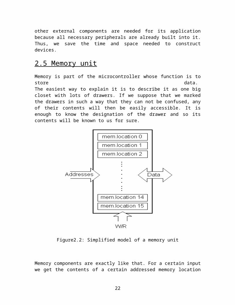
Memory is part of the microcontroller whose function is to store data. The easiest way to explain it is to describe it as one big closet with lots of drawers. If we suppose that we marked the drawers in such a way that they can not be confused, any of
13
their contents will then be easily accessible. It is enough to know the designation of the drawer and so its contents will be known to us for sure.
Figure2.2: Simplified model of a memory unit
Memory components are exactly like that. For a certain input we get the contents of a certain addressed memory location and that's all. Two new concepts are brought to us: addressing and memory location. Memory consists of all memory locations, and addressing is nothing but selecting one of them. This means that we need to select the desired memory location on one hand, and on the other hand we need to wait for the contents of that location. Besides reading from a memory location, memory must also provide for writing onto it. This is done by supplying an additional line called control line. We will designate this line as R/W (read/write). Control line is used in the following way: if r/w=1, reading is done, and if opposite is true then writing is done on the memory location. Memory is the first element, and we need a few operation of our microcontroller.
The amount of memory contained within a microcontroller varies between different microcontrollers. Some may not even have any integrated memory (e.g. Hitachi 6503, now discontinued). However, most modern microcontrollers will have integrated memory. The memory will be divided up into ROM and RAM, with typically more ROM than RAM.
14
Typically, the amount of ROM type memory will vary between around 512 bytes and 4096 bytes, although some 16 bit microcontrollers such as the Hitachi H8/3048 can have as much as 128 Kbytes of ROM type memory.
ROM type memory, as has already been mentioned, is used to store the program code. ROM memory can be ROM (as in One Time Programmable memory), EPROM, or EEPROM.
The amount of RAM memory is usually somewhat smaller, typically ranging between 25 bytes to 4 Kbytes.
RAM is used for data storage and stack management tasks. It is also used for register stacks (as in the microchip PIC range of microcontrollers).
2.6 Central Processing Unit
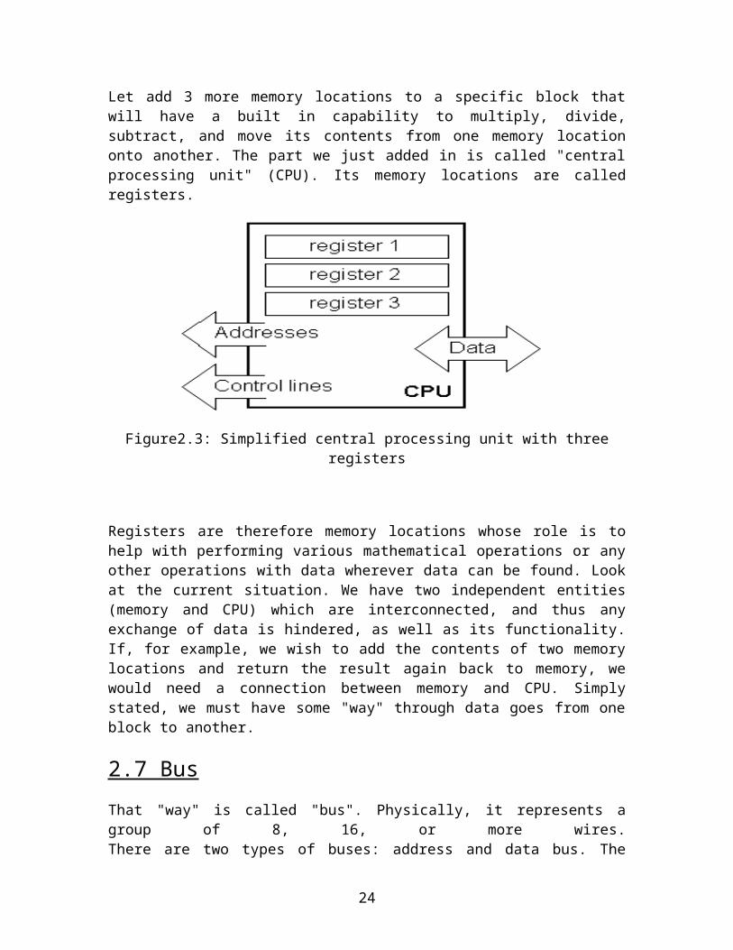
Let add 3 more memory locations to a specific block that will have a built in capability to multiply, divide, subtract, and move its contents from one memory location onto another. The part we just added in is called "central processing unit" (CPU). Its memory locations are called registers.
Figure2.3: Simplified central processing unit with three registers
Registers are therefore memory locations whose role is to help with performing various mathematical operations or any other operations with data wherever data can be found. Look at the current situation. We have two independent entities (memory and CPU) which are interconnected, and thus any exchange of data is hindered, as well as its functionality. If, for example, we wish to add the contents of two memory locations and return the result again back to memory, we would need a connection between memory
15

and CPU. Simply stated, we must have some "way" through data goes from one block to another.
2.7 Bus
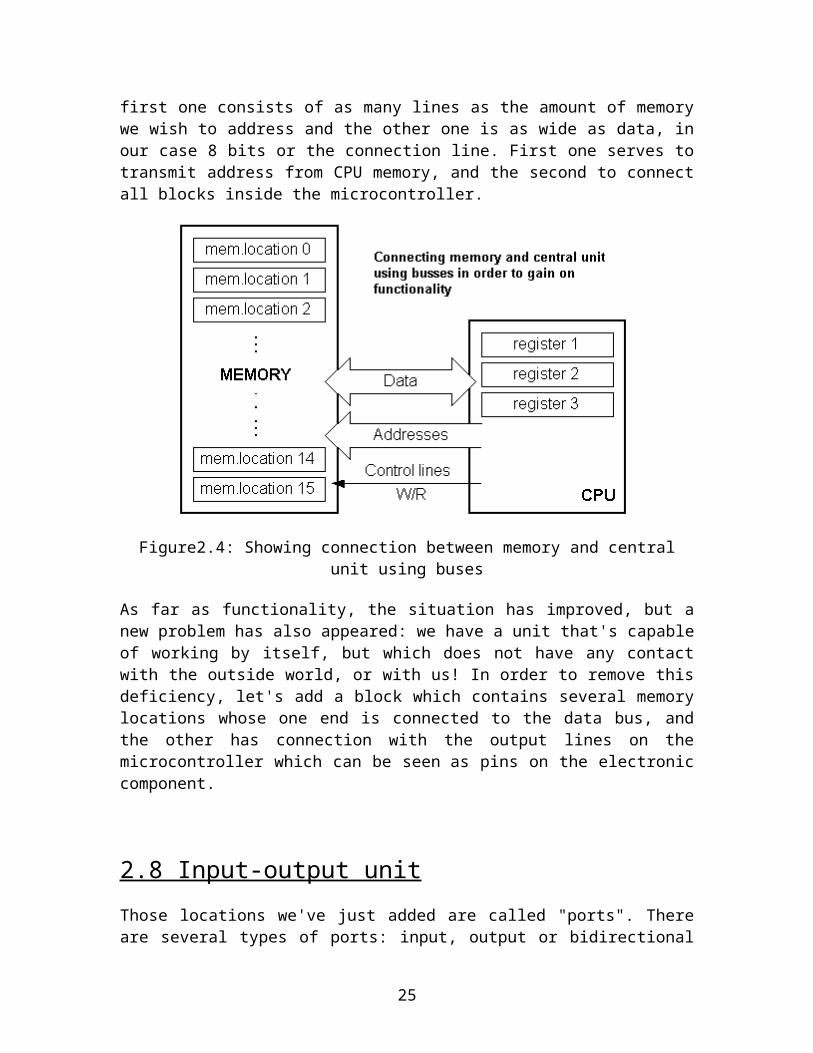
That "way" is called "bus". Physically, it represents a group of 8, 16, or more wires.There are two types of buses: address and data bus. The first one consists of as many lines as the amount of memory we wish to address and the other one is as wide as data, in our case 8 bits or the connection line. First one serves to transmit address from CPU memory, and the second to connect all blocks inside the microcontroller.
Figure2.4: Showing connection between memory and central unit using buses
As far as functionality, the situation has improved, but a new problem has also appeared: we have a unit that's capable of working by itself, but which does not have any contact with the outside world, or with us! In order to remove this deficiency, let's add a block which contains several memory locations whose one end is connected to the data bus, and the other has connection with the output lines on the microcontroller which can be seen as pins on the electronic component.
2.8 Input-output unit
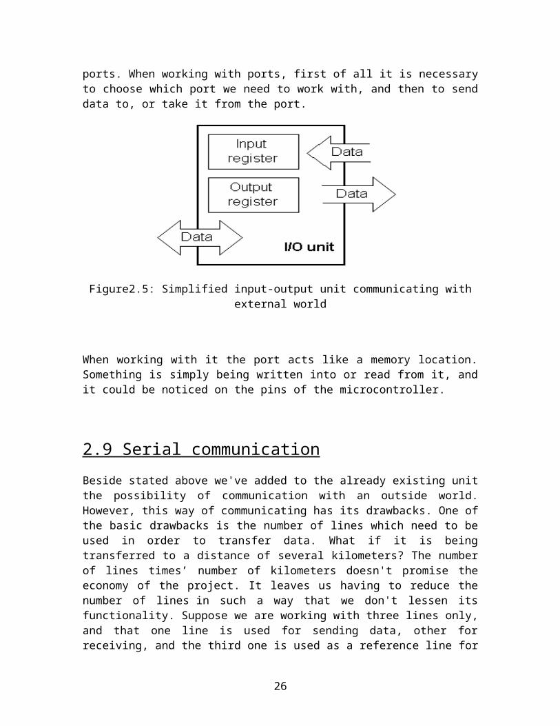
Those locations we've just added are called "ports". There are several types of ports: input, output or bidirectional ports. When working with ports, first of all it is necessary to choose which port we need to work with, and then to send data to, or take it from the port.
16
Figure2.5: Simplified input-output unit communicating with external world
When working with it the port acts like a memory location. Something is simply being written into or read from it, and it could be noticed on the pins of the microcontroller.
2.9 Serial communication
Beside stated above we've added to the already existing unit the possibility of communication with an outside world. However, this way of communicating has its drawbacks. One of the basic drawbacks is the number of lines which need to be used in order to transfer data. What if it is being transferred to a distance of several kilometers? The number of lines times’ number of kilometers doesn't promise the economy of the project. It leaves us having to reduce the number of lines in such a way that we don't lessen its functionality. Suppose we are working with three lines only, and that one line is used for sending data, other for receiving, and the third one is used as a reference line for both the input and the output side. In order for this to work, we need to set the rules of exchange of data. These rules are called protocol. Protocol is therefore defined in advance so there wouldn't be any misunderstanding between the sides that are communicating with each other. For example, if one man is speaking in French, and the other in English, it is highly unlikely that they will quickly and effectively understand each other. Let's suppose we have the following protocol. The logical unit "1" is set up on the transmitting line until transfer begins. Once the transfer starts, we lower the transmission line to logical "0" for a period of time (which we will designate as T), so the receiving side will know that it is receiving data, and so it will activate its mechanism for reception. Let's go back now to the transmission side and start putting logic zeros and ones onto the transmitter line in the order from a bit of the lowest value to a bit of the highest value. Let each bit stay on line for a time period which is equal to T, and in the end, or after the 8th bit, let us bring the logical unit "1" back on the line which will mark
17
the end of the transmission of one data. The protocol we've just described is called in professional literature NRZ (Non-Return to Zero).
Figure2.6: Serial unit sending data through three lines only
As we have separate lines for receiving and sending, it is possible to receive and send data (info.) at the same time. So called full-duplex mode block which enables this way of communication is called a serial communication block. Unlike the parallel transmission, data moves here bit by bit, or in a series of bits what defines the term serial communication comes from. After the reception of data we need to read it from the receiving location and store it in memory as opposed to sending where the process is reversed. Data goes from memory through the bus to the sending location, and then to the receiving unit according to the protocol.
2.10 Timer unit
Since we have the serial communication explained, we can receive, send and process data.
Figure2.7: Timer unit generating signals in regular time intervals
However, in order to utilize it in industry we need a few additionally blocks. One of those is the timer block which is significant to us because it can give us information about time,
18
duration, protocol etc. The basic unit of the timer is a free-run counter which is in fact a register whose numeric value increments by one in even intervals, so that by taking its value during periods T1 and T2 and on the basis of their difference we can determine how much time has elapsed. This is a very important part of the microcontroller whose understanding requires most of our time.
2.11 Watchdog
One more thing is requiring our attention is a flawless functioning of the microcontroller during its run-time. Suppose that as a result of some interference (which often does occur in industry) our microcontroller stops executing the program, or worse, it starts working incorrectly.
Figure2.8: Watchdog
Of course, when this happens with a computer, we simply reset it and it will keep working. However, there is no reset button we can push on the microcontroller and thus solve our problem. To overcome this obstacle, we need to introduce one more block called watchdog. This block is in fact another free-run counter where our program needs to write a zero in every time it executes correctly. In case that program gets "stuck", zero will not be written in, and counter alone will reset the microcontroller upon achieving its maximum value. This will result in executing the program again, and correctly this time around. That is an important element of every program to be reliable without man's supervision.
2.12 Analog to Digital Converter
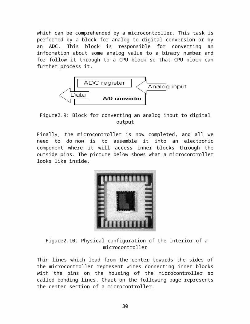
As the peripheral signals usually are substantially different from the ones that microcontroller can understand (zero and one), they have to be converted into a pattern which can be comprehended by a microcontroller. This task is performed by a block for analog to digital conversion or by an ADC. This block is responsible for converting an information about some analog value to a binary number and for follow it through to a CPU block so that CPU block can further process it.
19
Figure2.9: Block for converting an analog input to digital output
Finally, the microcontroller is now completed, and all we need to do now is to assemble it into an electronic component where it will access inner blocks through the outside pins. The picture below shows what a microcontroller looks like inside.
Figure2.10: Physical configuration of the interior of a microcontroller
Thin lines which lead from the center towards the sides of the microcontroller represent wires connecting inner blocks with the pins on the housing of the microcontroller so called bonding lines. Chart on the following page represents the center section of a microcontroller.
20
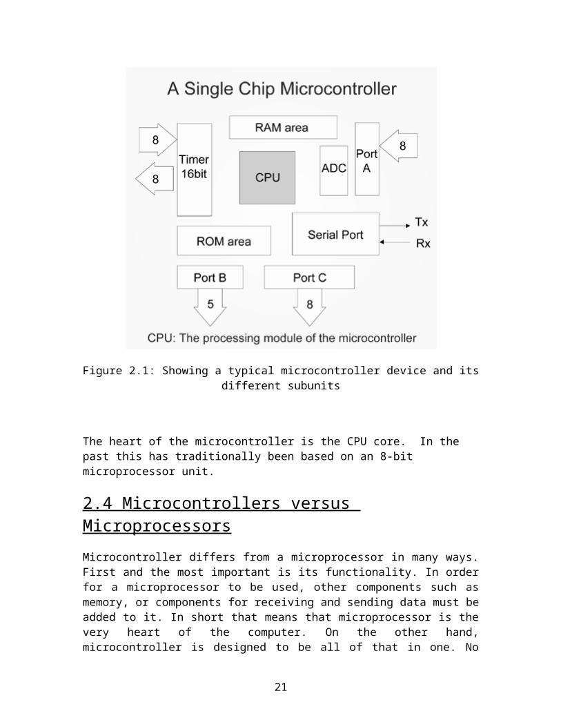
Figure2.11: Microcontroller outline with basic elements and internal connections
For a real application, a microcontroller alone is not enough. Beside a microcontroller, we need a program that would be executed, and a few more elements which make up interface logic towards the elements of regulation (which will be discussed in later chapters).
21
3. INTRODUCTION TO EEPROM
3.1 EEPROM
EEPROM means Electrical Erasable Programmable Read Only Memory and also referred to as E²PROM chip or i2c. As the name suggest, an EEPROM can be both erased and programmed with electrical pulses from a programmer kit, burner or the equipment itself. Since it can be both electrically written into and electrically erased, the EEPROM IC can be quickly programmed and erased in circuit for reprogramming without taking them out from the main board. EEPROM IC is also called a non-volatile memory because when the power is switched off, the stored data (information) in the EEPROM IC will not be erased or corrupt and the data is still intact. New EEPROM IC have no data (blank) inside and normally have to program it first with a programmer tools before it can be use on electron IC circuit.
Figure3.1: Showing EEPROM of Atmel
If you just installed a new or blank EEPROM IC into a main board, even though with the same part number, I can say that the equipment will surely not going to work because the CPU or microprocessor do not know how to function. Information or data stored in this type of memory can be retained for many years even without a continuous dc power supply to the IC.
3.2 Application/ Operation of EEPROM
EEPROMs mainly store user programmable information such as: -
22

VCR programming information or data CD programming information or data Digital satellite receiver control data or information User information on various consumer products such as in Television.
The EEPROM IC in Computer Monitor performs two tasks: -
When a monitor is turn on it will copies all the data or information from the EEPROM to the microprocessor or CPU. For instance, the EEPROM will let the CPU know the frequencies at which the monitor is going to run.
The EEPROM IC is used to store the current settings of the Monitor. The current settings of the monitor will not be erased even when the monitor is switched off. Anytime when a change is made in the monitor settings, the CPU updates the setting in the EEPROM (store data in EEPROM). When the monitor is switch on again, the stored settings in EEPROM IC are used to set up the monitor for operation.
Assuming the data file in MONITOR or TV’s EEPROM are corrupted damaged and failure detected, what would be the display symptoms like?
There would be no high voltage (no display) because the CPU don’t activate the 12 volt line supply to the horizontal and vertical oscillator IC.
The IC will not save (store) the current setting of the equipment Some control functions like sound, brightness, horizontal size and contrast
control will not work. The On Screen Display (OSD) would not work or the OSD will have a corrupted
or erratic display. Equipment high voltage will shut down (EEPROM set wrongly the horizontal
frequency and will lead to a failure of the horizontal output transistor (HOT)).
Typical EEPROM part numbers are: - 2402, 2404, 240824C02, 24C04, 24C08, 24C1624C325, 24C645AT17C65, AT17C12893C06, 93C46, 93C56, 93C6625010, 25020, 25040
23
4. INTRODUCTION TO 16X2 LCD DISPLAY
LCD stands for Liquid Crystal Display. The most commonly used LCDs found in the market today are 1 Line, 2 Line or 4 Line LCDs which have only 1 controller and support at most of 80 characters.
4.1 Pin Description
Most LCDs with two controllers has 16 Pins. Pin description is shown in the table below.
Pin No. Name Description
Pin no. 1 D7 Data bus line 7 (MSB)
Pin no. 2 D6 Data bus line 6
Pin no. 3 D5 Data bus line 5
Pin no. 4 D4 Data bus line 4
Pin no. 5 D3 Data bus line 3
Pin no. 6 D2 Data bus line 2
Pin no. 7 D1 Data bus line 1
Pin no. 8 D0 Data bus line 0 (LSB)
Pin no. 9 EN1 Enable signal for row 0 and 1 (1stcontroller)
Pin no. 10 R/W0 = Write to LCD module1 = Read from LCD module
Pin no. 11 RS0 = Instruction input1 = Data input
Pin no. 12 VEE Contrast adjust
Pin no. 13 VSS Power supply (GND)
Pin no. 14 VCC Power supply (+5V)
Pin no. 15 EN2 Enable signal for row 2 and 3 (2ndcontroller)
Pin no. 16 NC Not Connected
Table No.4.1: Pin description of the LCD
4.2 DDRAM - Display Data RAM
24
Display data RAM (DDRAM) stores display data represented in 8-bit character codes. Its extended capacity is 80 X 8 bits, or 80 characters. The area in display data RAM (DDRAM) that is not used for display can be used as general data RAM. So whatever you send on the DDRAM is actually displayed on the LCD.
4.3 BF - Busy Flag
Busy Flag is a status indicator flag for LCD. When we send a command or data to the LCD for processing, this flag is set (i.e. BF =1) and as soon as the instruction is executed successfully this flag is cleared (BF = 0). This is helpful in producing and exact amount of delay. For the LCD processing. To read Busy Flag, the condition RS = 0 and R/W = 1 must be met and The MSB of the LCD data bus (D7) act as busy flag. When BF = 1 means LCD is busy and will not accept next command or data and BF = 0 means LCD is ready for the next command or data to process.
4.4 Instruction Register (IR) and Data Register (DR)
There are two 8-bit registers controller Instruction and Data register. Instruction register corresponds to the register where you send commands to LCD e.g. LCD shift command, LCD clear, LCD address etc. and Data register is used for storing data which is to be displayed on LCD. When send the enable signal of the LCD is asserted, the data on the pins is latched in to the data register and data is then moved automatically to the DDRAM and hence is displayed on the LCD.
4.5 Commands and Instruction set
Only the instruction register (IR) and the data register (DR) of the LCD can be controlled by the MCU. Before starting the internal operation of the LCD, control information is temporarily stored into these registers to allow interfacing with various MCUs, which operate at different speeds, or various peripheral control devices. The internal operation of the LCD is determined by signals sent from the MCU.
4.6 Sending Commands to LCD
To send commands we simply need to select the command register. Everything is same as we have done in the initialization routine. But we will summarize the common steps and put them in a single subroutine.
Following are the steps: Move data to LCD port Select command register
25
Select write operation Send enable signal Wait for LCD to process the command
26

5. INTRODUCTION TO I2C BUS
5.1 Basic Definition
An Inter-IC bus is often used to communicate across circuit-board distances.
At the low end of the spectrum of communication options for "inside the box" communication is I2C ("eye-squared-see"). The name I2C is shorthand for a standard Inter-IC (integrated circuit) bus.
I2C provides good support for communication with various slow, on-board peripheral devices that are accessed intermittently, while being extremely modest in its hardware resource needs. It is a simple, low-bandwidth, short-distance protocol. Most available I2C devices operate at speeds up to 400Kbps, with some venturing up into the low megahertz range. I2C is easy to use to link multiple devices together since it has a built-in addressing scheme.
Philips originally developed I2C for communication between devices inside of a TV set. Examples of simple I2C-compatible devices found in embedded systems include EEPROMs, thermal sensors, and real-time clocks. I2C is also used as a control interface to signal processing devices that have separate, application-specific data interfaces. For instance, it's commonly used in multimedia applications, where typical devices include RF tuners, video decoders and encoders, and audio processors. In all, Philips, National Semiconductor, Xicor, Siemens, and other manufacturers offer hundreds of I2C-compatible devices.
5.2 Inside the box
I2C is appropriate for interfacing to devices on a single board, and can be stretched across multiple boards inside a closed system, but not much further. An example is a host CPU on a main embedded board using I2C to communicate with user interface devices located on a separate front panel board. A second example is SDRAM DIMMs, which can feature an I2C EEPROM containing parameters needed to correctly configure a memory controller for that module.
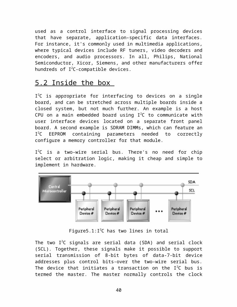
I2C is a two-wire serial bus. There's no need for chip select or arbitration logic, making it cheap and simple to implement in hardware.
27
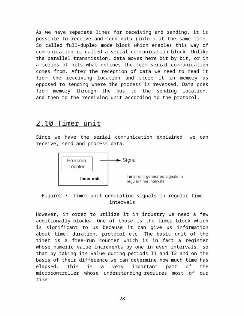
Figure5.1:I2C has two lines in total
The two I2C signals are serial data (SDA) and serial clock (SCL). Together, these signals make it possible to support serial transmission of 8-bit bytes of data-7-bit device addresses plus control bits-over the two-wire serial bus. The device that initiates a transaction on the I2C bus is termed the master. The master normally controls the clock signal. A device being addressed by the master is called a slave.
In a bind, an I2C slave can hold off the master in the middle of a transaction using what's called clock stretching (the slave keeps SCL pulled low until it's ready to continue). Most I2C slave devices don't use this feature, but every master should support it.
The I2C protocol supports multiple masters, but most system designs include only one. There may be one or more slaves on the bus. Both masters and slaves can receive and transmit data bytes.
Each I2C-compatible hardware slave device comes with a predefined device address, the lower bits of which may be configurable at the board level. The master transmits the device address of the intended slave at the beginning of every transaction. Each slave is responsible for monitoring the bus and responding only to its own address. This addressing scheme limits the number of identical slave devices that can exist on an I 2C bus without contention, with the limit set by the number of user-configurable address bits (typically two bits, allowing up to four identical devices).
5.3 Communication
As you can see in Figure 2, the master begins the communication by issuing the start condition (S). The master continues by sending a unique 7-bit slave device address, with the most significant bit (MSB) first. The eighth bit after the start, read/not-write (), specifies whether the slave is now to receive (0) or to transmit (1). This is followed by an ACK bit issued by the receiver, acknowledging receipt of the previous byte. Then the transmitter (slave or master, as indicated by the bit) transmits a byte of data starting with the MSB. At the end of the byte, the receiver (whether master or slave) issues a new ACK bit. This 9-bit pattern is repeated if more bytes need to be transmitted.
28
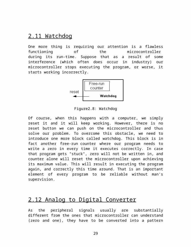
Figure5.2: I2C communication
In a write transaction (slave receiving), when the master is done transmitting all of the data bytes it wants to send, it monitors the last ACK and then issues the stop condition (P). In a read transaction (slave transmitting), the master does not acknowledge the final byte it receives. This tells the slave that its transmission is done. The master then issues the stop condition.
5.4 A simple bus
As we've seen, the I2C signaling protocol provides device addressing, a read/write flag, and a simple acknowledgement mechanism. There are a few more elements to the I 2C protocol, such as general call (broadcast) and 10-bit extended addressing. Beyond that, each device defines its own command interface or address-indexing scheme.
Standard I2C devices operate up to 100Kbps, while fast-mode devices operate at up to 400Kbps. A 1998 revision of the I2C specification (v. 2.0) added a high-speed mode running at up to 3.4Mbps. Most of the I2C devices available today support 400Kbps operation. Higher-speed operation may allow I2C to keep up with the rising demand for bandwidth in multimedia and other applications.
Most often, the I2C master is the CPU or microcontroller in the system. Some microcontrollers even feature hardware to implement the I2C protocol. You can also build an all-software implementation using a pair of general-purpose I/O pins (single master implementations only).
Since the I2C master controls transaction timing, the bus protocol doesn't impose any real-time constraints on the CPU beyond those of the application. (This is in contrast with other serial buses that are timeslot-based and, therefore, take their service overhead even when no real communication is taking place.)
5.5 The elegance of I 2 C
I2C offers good support for communication with on-board devices that are accessed on an occasional basis. I2C's competitive advantage over other low-speed short-distance communication schemes is that its cost and complexity don't scale up with the number of devices on the bus. On the other hand, the complexity of the supporting I2C software components can be significantly higher than that of several competing schemes (SPI and
29
Micro Wire, to name two) in a very simple configuration. With its built-in addressing scheme and straightforward means to transfer strings of bytes, I2C is an elegant, minimalist solution for modest, "inside the box" communication needs.
30

6. PROJECT DESCRIPTION
The EVM consist of two units: ballot unit (BU) and control unit (CU). Following figure shows the complete EVM system, including the constituents of both units as well as the signals exchanged between them.
Figure 6.1: Block diagram of EVM
31

6.1 BALLOT UNIT:
6.1(a) BLOCK DIAGRAM:
Figure 6.2: Block diagram of ballot unit
6.1(b) GENERAL WORKING:
1. When the power of Ballot unit is turned on, the ballot unit awaits a “READY SIGNAL” from control unit.
2. After getting “READY SIGNAL”, ballot unit glows its “MACHINE READY” LED indicating that the machine is ready to accept a new vote from its candidate panel.
3. Once the voter presses the button corresponding to the candidate of her/his choice, a four-bit code is generated and sent to the control unit.
4. Turn off the “MACHINE READY” LED.5. This implies that any new vote cannot be cast now.6. The ballot unit waits for the “VOTE SIGNAL” to become low from control unit,
which indicate that control unit has counted that for respective candidate.7. After “VOTE SIGNAL” goes low, the ballet unit glows the “VOTE CAST LED”
on the vote cast panel for the corresponding candidate whose vote is being cast.8. At this time, the buzzer also generates a beep sound. This indicates to the voter
that her/his vote has been processed.9. The machine returns to the step 1 and starts all over again for next voting.
32

6.1(c) FLOWCHART:
Figure 6.3: Flowchart to demonstrate program flow/ working of ballot unit
33
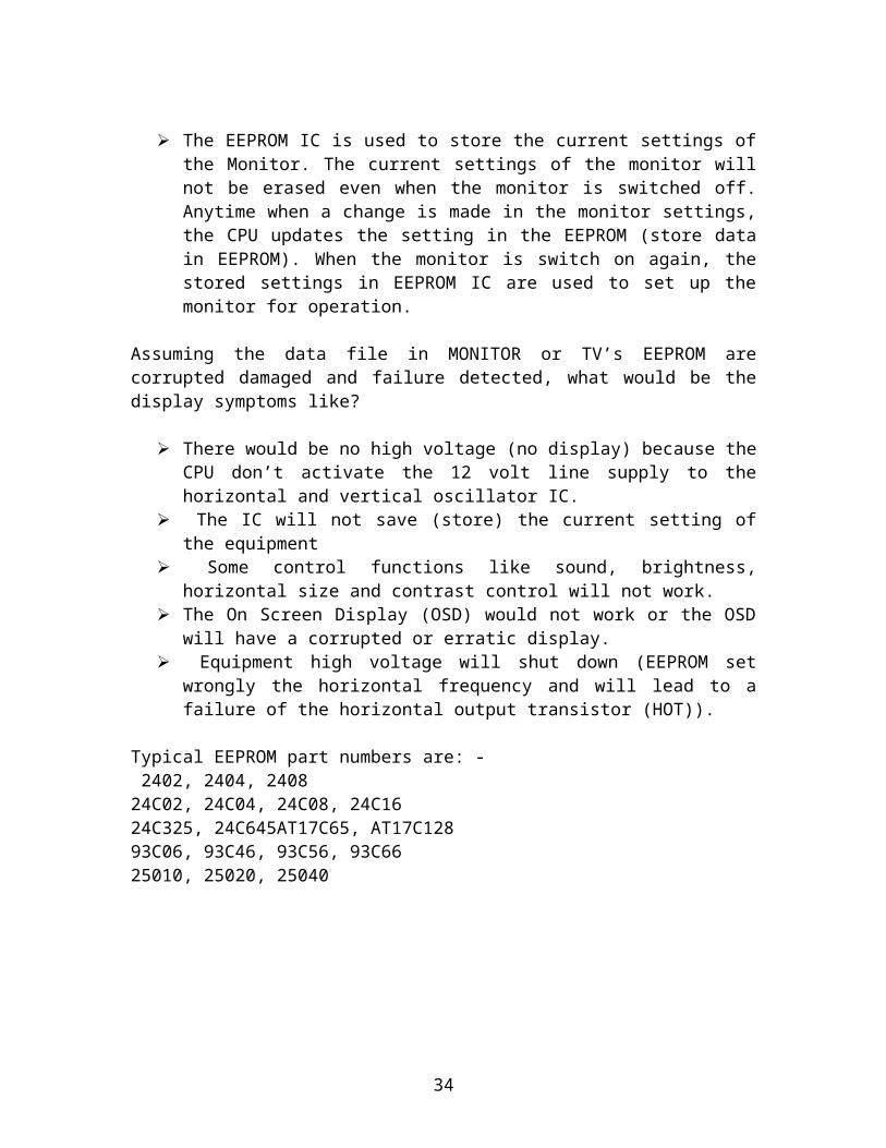
Figure 6.3 (contd.)…..
34

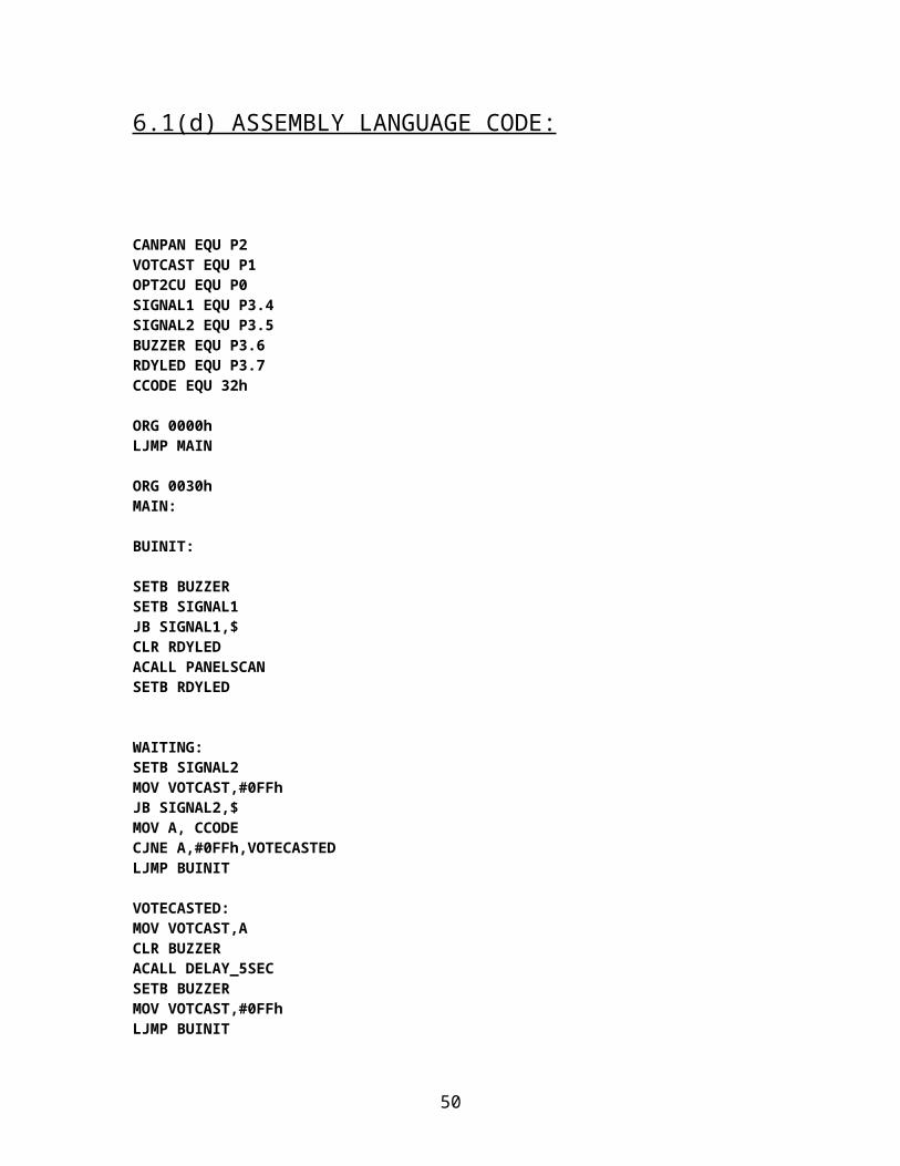
6.1(d) ASSEMBLY LANGUAGE CODE:
CANPAN EQU P2VOTCAST EQU P1OPT2CU EQU P0SIGNAL1 EQU P3.4 SIGNAL2 EQU P3.5 BUZZER EQU P3.6 RDYLED EQU P3.7 CCODE EQU 32h
ORG 0000h LJMP MAIN
ORG 0030h MAIN:
BUINIT:
SETB BUZZERSETB SIGNAL1 JB SIGNAL1,$ CLR RDYLED ACALL PANELSCANSETB RDYLED
WAITING:SETB SIGNAL2 MOV VOTCAST,#0FFh JB SIGNAL2,$ MOV A, CCODECJNE A,#0FFh,VOTECASTED LJMP BUINIT
VOTECASTED:MOV VOTCAST,A CLR BUZZERACALL DELAY_5SECSETB BUZZERMOV VOTCAST,#0FFhLJMP BUINIT
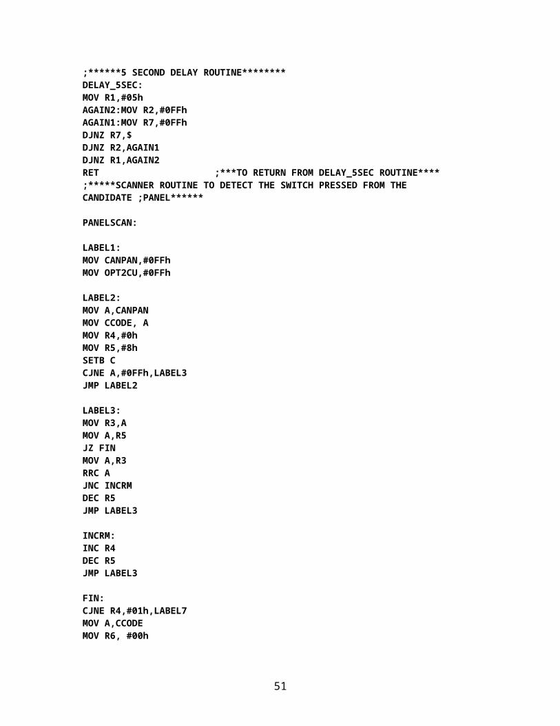
;******5 SECOND DELAY ROUTINE********DELAY_5SEC: MOV R1,#05hAGAIN2:MOV R2,#0FFh AGAIN1:MOV R7,#0FFhDJNZ R7,$DJNZ R2,AGAIN1
35

DJNZ R1,AGAIN2RET ;***TO RETURN FROM DELAY_5SEC ROUTINE****;*****SCANNER ROUTINE TO DETECT THE SWITCH PRESSED FROM THE CANDIDATE ;PANEL******
PANELSCAN:
LABEL1:MOV CANPAN,#0FFh MOV OPT2CU,#0FFh
LABEL2: MOV A,CANPAN MOV CCODE, AMOV R4,#0h MOV R5,#8h SETB CCJNE A,#0FFh,LABEL3 JMP LABEL2
LABEL3:MOV R3,A MOV A,R5 JZ FINMOV A,R3RRC A JNC INCRM DEC R5 JMP LABEL3
INCRM:INC R4 DEC R5 JMP LABEL3
FIN:CJNE R4,#01h,LABEL7 MOV A,CCODE MOV R6, #00h
LABEL5:RRC A INC R6 JNC LABEL6JC LABEL5
LABEL6:MOV A,R6 MOV OPT2CU, A JMP ENDING
LABEL7:
MOV CCODE,#0FFh .MOV A,#09hMOV OPT2CU, A JMP ENDING
36

ENDING:NOPNOPNOPNOPMOV CANPAN,#0FFh MOV OPT2CU,#0FFh
RET ;***TO RETURN FROM PANELSCAN ROUTINE****
END
37

6.2 CONTROL UNIT:
6.2(a) BLOCK DIAGRAM:
Figure6.5: Block diagram of control unit
6.2(b) GENERAL WORKING:
1. When power of control unit is turned on, the CU reads the status of the machine form the EPROM into the accumulator.
2. On the basis of the status read from accumulator the CU goes into one of the two modes (A) Voting mode.(B) Result mode.
3. Let us assume that machine enters the voting mode.
38

(A) VOTING MODE:i. Now the LCD displays “VOTING MODE STARTING…..” .
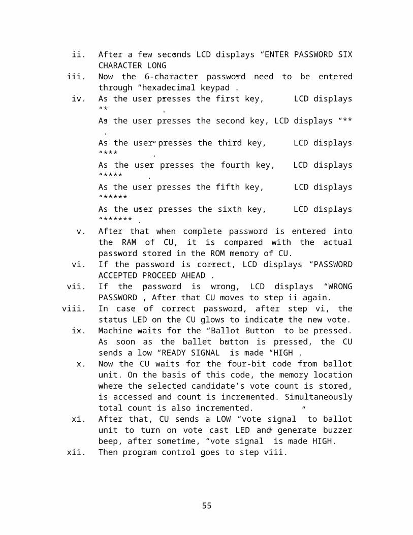
ii. After a few seconds LCD displays “ENTER PASSWORD SIX CHARACTER LONG”
iii. Now the 6-character password need to be entered through “hexadecimal keypad”.
iv. As the user presses the first key, LCD displays “* ”.As the user presses the second key, LCD displays “** ”.As the user presses the third key, LCD displays “*** ”.As the user presses the fourth key, LCD displays “**** ”.As the user presses the fifth key, LCD displays “***** ”As the user presses the sixth key, LCD displays “******”.
v. After that when complete password is entered into the RAM of CU, it is compared with the actual password stored in the ROM memory of CU.
vi. If the password is correct, LCD displays “PASSWORD ACCEPTED PROCEED AHEAD”.
vii. If the password is wrong, LCD displays “WRONG PASSWORD”, After that CU moves to step ii again.
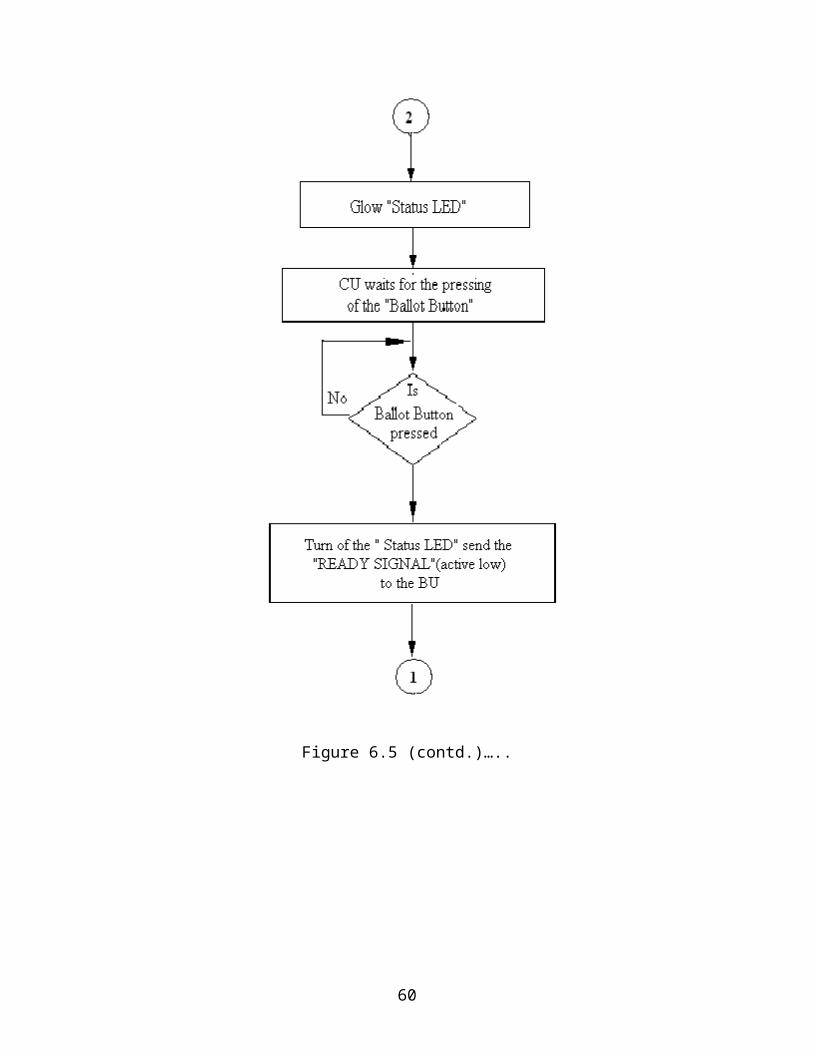
viii. In case of correct password, after step vi, the status LED on the CU glows to indicate the new vote.
ix. Machine waits for the “Ballot Button” to be pressed. As soon as the ballet button is pressed, the CU sends a low “READY SIGNAL” is made “HIGH”.
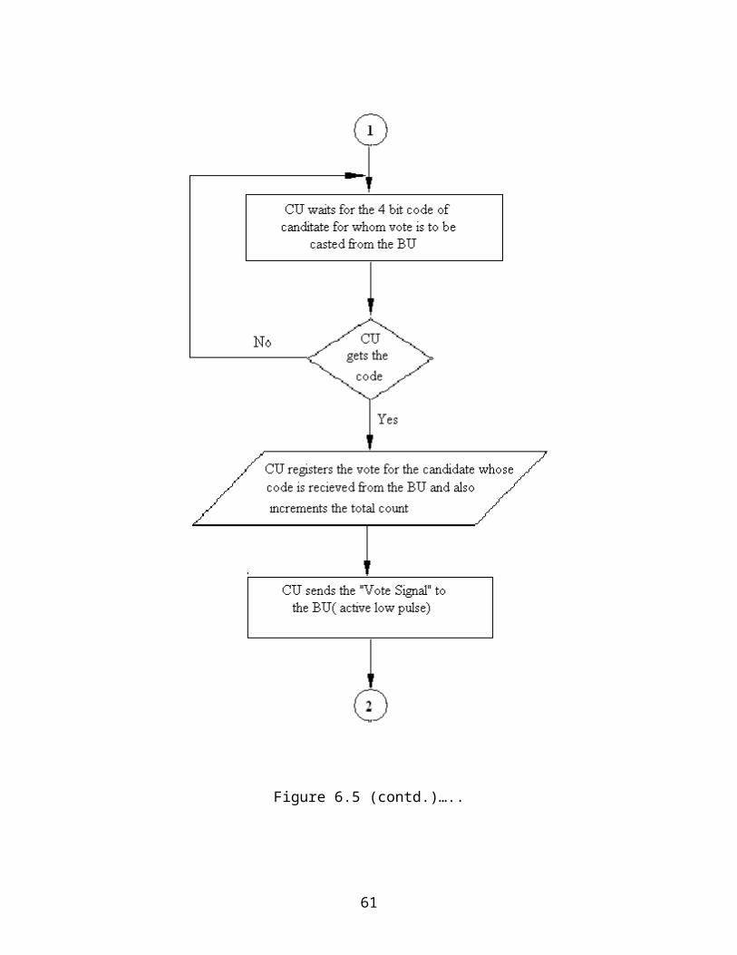
x. Now the CU waits for the four-bit code from ballot unit. On the basis of this code, the memory location where the selected candidate’s vote count is stored, is accessed and count is incremented. Simultaneously total count is also incremented.
xi. After that, CU sends a LOW “vote signal” to ballot unit to turn on vote cast LED and generate buzzer beep, after sometime, “vote signal” is made HIGH.
xii. Then program control goes to step viii.xiii. After the voting is complete, i.e. the last voter has cast his/her vote or in case
of booth capture, the “CLOSE” button is pressed.
(B) RESULT MODE:
i. Now the LCD displays “RESULT MODE STRARTING…..”.ii. After a few seconds LCD displays “ENTER PASSWORD SIX
CHARACTER LONG”iii. Now the 6-character password needs to be entered through “hexadecimal
keypad”.iv. As the user presses the first key, LCD displays “* ”.
As the user presses the second key, LCD displays “** ”.As the user presses the third key, LCD displays “*** ”.As the user presses the fourth key, LCD displays “**** ”.As the user presses the fifth key, LCD displays “***** ”As the user presses the sixth key, LCD displays “******”.
39
v. After that when complete password is entered into the RAM of CU, it is compared with the actual password stored in the ROM memory of CU.
vi. If the password is correct, LCD displays “PASSWORD ACCEPTED PROCEED AHEAD”.
vii. If the password is wrong, LCD displays “WRONG PASSWORD”, After that CU moves to step ii again.
viii. The LCD displays “CANDIDATE #1 VOTES : ______”.ix. Now it waits for the result button to be pressed, the result of next candidate is
displayed.x. Step ix is repeated to get result of all the candidates.
TOTAL (Interrupt controlled button)
1. Whenever, the “TOTAL” button is pressed, an interrupt is generated and an Interrupt service routine is called.
2. This ISR retrieves the total vote count from EEPROM and displays it on the LCD.
CLOSE (Interrupt Controlled Button)
1. Whenever the “CLOSE” button is pressed, an interrupt is generated and an ISR is called.
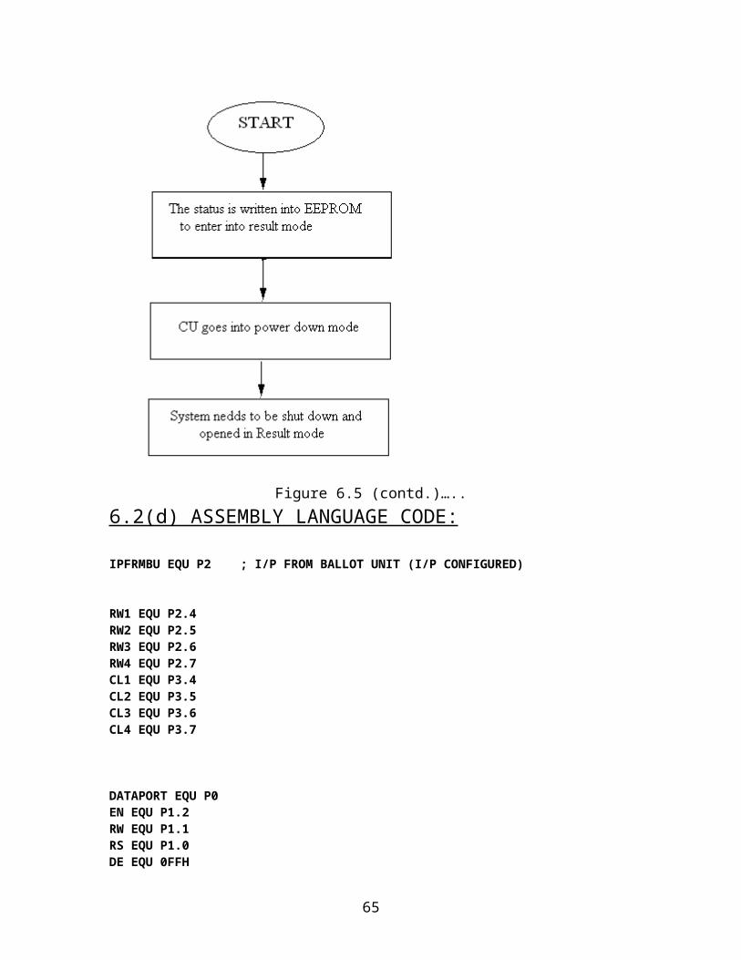
2. The value of status is written in EEPROM to make the machine enter into the result mode, when the machine is powered on next time.
3. The machine goes in “POWER DOWN” mode.
40
6.2(c) FLOWCHART:
Figure 6.5: Flowchart to demonstrate program flow/ working of control unit
41

Figure 6.5 (contd.)…..
42
Figure 6.5 (contd.)…..
43

Figure 6.5 (contd.)…..
44
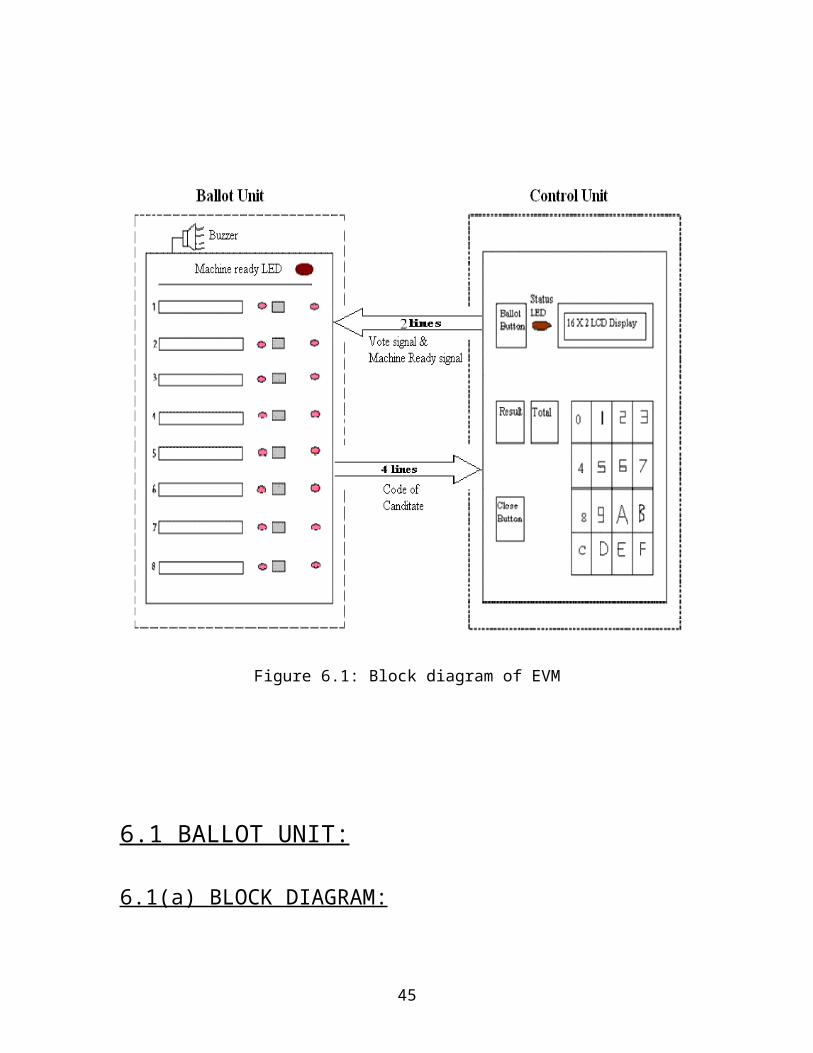
Figure 6.5 (contd.)…..
45

Figure 6.5 (contd.)…..
46

TOTAL BUTTON:
CLOSE BUTTON:
Figure 6.5 (contd.)…..
47

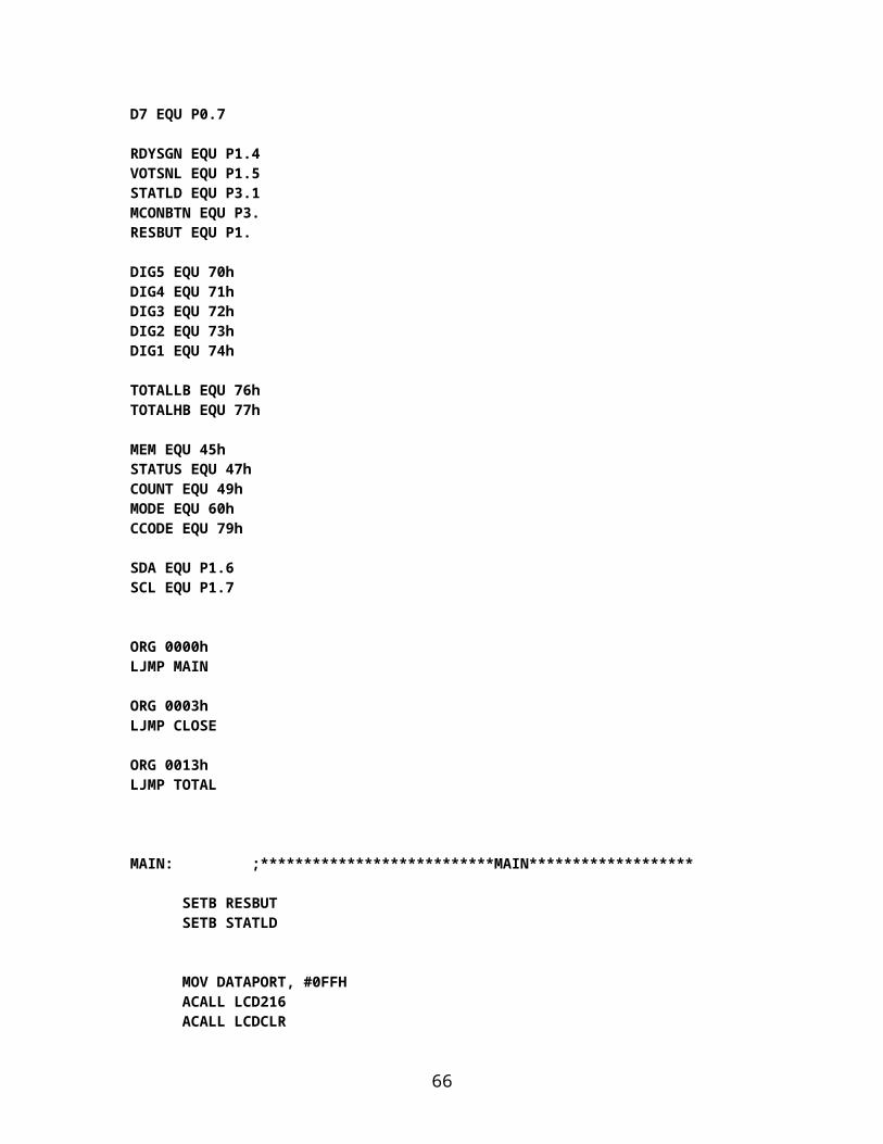
6.2(d) ASSEMBLY LANGUAGE CODE:
IPFRMBU EQU P2 ; I/P FROM BALLOT UNIT (I/P CONFIGURED)
RW1 EQU P2.4 RW2 EQU P2.5 RW3 EQU P2.6 RW4 EQU P2.7 CL1 EQU P3.4 CL2 EQU P3.5 CL3 EQU P3.6 CL4 EQU P3.7
DATAPORT EQU P0EN EQU P1.2RW EQU P1.1RS EQU P1.0DE EQU 0FFH D7 EQU P0.7
RDYSGN EQU P1.4 VOTSNL EQU P1.5 STATLD EQU P3.1 MCONBTN EQU P3. RESBUT EQU P1.
DIG5 EQU 70hDIG4 EQU 71hDIG3 EQU 72h DIG2 EQU 73hDIG1 EQU 74h
TOTALLB EQU 76hTOTALHB EQU 77h
MEM EQU 45hSTATUS EQU 47h COUNT EQU 49hMODE EQU 60h CCODE EQU 79h
SDA EQU P1.6SCL EQU P1.7
ORG 0000hLJMP MAIN
ORG 0003hLJMP CLOSE ORG 0013h
48

LJMP TOTAL
MAIN: ;***************************MAIN*******************
SETB RESBUTSETB STATLD
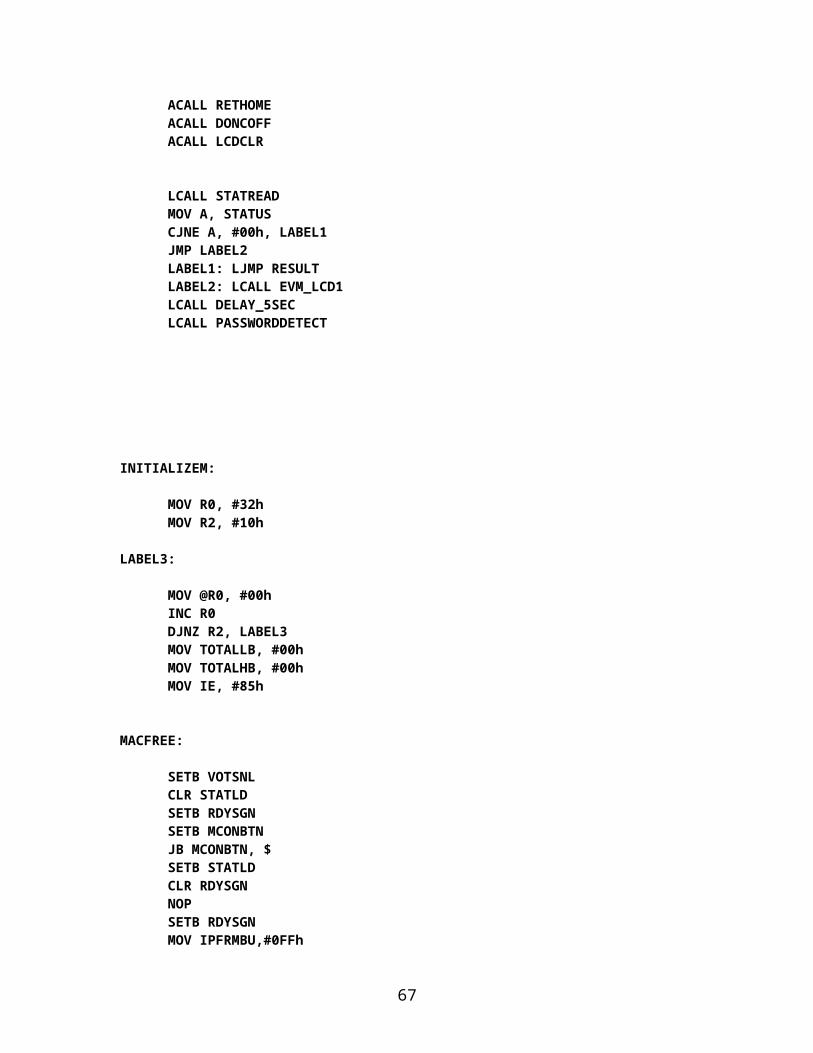
MOV DATAPORT, #0FFH ACALL LCD216 ACALL LCDCLR ACALL RETHOMEACALL DONCOFF ACALL LCDCLR
LCALL STATREADMOV A, STATUSCJNE A, #00h, LABEL1 JMP LABEL2 LABEL1: LJMP RESULT LABEL2: LCALL EVM_LCD1LCALL DELAY_5SECLCALL PASSWORDDETECT
INITIALIZEM:
MOV R0, #32hMOV R2, #10h
LABEL3:
MOV @R0, #00hINC R0DJNZ R2, LABEL3MOV TOTALLB, #00hMOV TOTALHB, #00hMOV IE, #85h
MACFREE:
SETB VOTSNLCLR STATLD SETB RDYSGN SETB MCONBTN JB MCONBTN, $ SETB STATLD CLR RDYSGN
49
NOPSETB RDYSGNMOV IPFRMBU,#0FFh
REFRESH:
MOV A, IPFRMBUANL A, #00001111bCJNE A, #00h, REFRESH
START:
MOV IPFRMBU, #0FFh MOV A, IPFRMBUANL A, #00001111bCJNE A, #0Fh,START1JMP START
START1:
MOV A, IPFRMBUANL A, #00001111bCJNE A, #09h, VALIDCLR VOTSNLSETB VOTSNLJMP MACFREE
VALID: ;*******INCREMENTING VOTE(INDIVIDUAL & TOTAL) AND WRITING IT TO EEPROM*******
MOV CCODE, AMOV R2, TOTALLBCJNE R2, #0FFh, LABEL11 INC TOTALHB MOV TOTALLB, #00h JMP LABEL12
LABEL11:
INC TOTALLB
LABEL12:
LCALL TOTALWRITEMOV R1, #30h MOV B, #02h MOV A, CCODEMUL ABADD A, R1MOV R1, AMOV A,@R1
50
CJNE A, #0FFh, INCRMINC R1MOV A,@R1INC AMOV @R1, ADEC R1MOV @R1, #00hJMP COMP
INCRM:
INC A MOV @R1, A
COMP: CLR VOTSNL
LCALL VOTEWRITEACALL DELAY_5SEC
SETB VOTSNL LJMP MACFREE
RESULT: ;*******************************RESULT ROUTINE*******************
LCALL EVM_LCD5 LCALL DELAY_5SEC LCALL PASSWORDDETECTMOV IE, #84hMOV COUNT, #00hLCALL VOTEREADLCALL STATWRITE0 LABEL14:
MOV R0, #32hMOV A, COUNTMOV B, #02hMUL ABADD A, R0MOV R0, AMOV A,@R0MOV R2, AINC R0MOV A,@R0MOV R1, A ACALL CONVERSION
MOV DATAPORT,#0FFH ACALL LCD216
51

ACALL LCDCLR ACALL RETHOME ACALL DONCOFF ACALL LCDCLR ACALL FCBFL ACALL COMMAND ACALL EVM_LCDO
ACALL DELAY_5SECJB RESBUT,$INC COUNTMOV A,COUNTCJNE A,#08h,LABEL14MOV COUNT,#00hJMP LABEL14
EVM_LCDO:
MOV DPTR, #TABLE1OMOV A, COUNTCLR CMOV B, #0ChMUL ABADD A, DPLMOV DPL, AMOV A, #00hADDC A, DPHMOV DPH, A
ACALL WRITE1O ACALL FCBSL ACALL COMMAND
MOV DPTR, #TABLE2O ACALL WRITE2O RET
WRITE1O:
CLR A MOVC A,@A+DPTR JZ BACK2O ACALL DISPLAY INC DPTR SJMP WRITE1O
BACK2O: RET TABLE1O:
DB 'CANDIDATE 1', 0 DB 'CANDIDATE 2', 0 DB 'CANDIDATE 3', 0 DB 'CANDIDATE 4', 0 DB 'CANDIDATE 5', 0 DB 'CANDIDATE 6', 0
52
DB 'CANDIDATE 7', 0 DB 'CANDIDATE 8', 0
WRITE2O:
CLR AMOVC A,@A+DPTR
JZ BACK3O ACALL DISPLAY INC DPTR SJMP WRITE2O
BACK3O:
ACALL BACK3RET
TABLE2O:
DB 'VOTES: ', 0
;**************************** CLOSE ROUTINE************************************
CLOSE:
SETB STATLDLCALL STATWRITE1MOV A, PCONORL A, #02hMOV PCON, ARETI
;******************************TOTAL ROUTINE **********************************
TOTAL:
LCALL TOTALREADMOV R2, TOTALLB
53

MOV R1, TOTALHBLCALL CONVERSION
MOV DATAPORT, #0FFH ACALL LCD216 ACALL LCDCLR ACALL RETHOME ACALL DONCOFF ACALL LCDCLR ACALL FCBFL ACALL COMMAND
ACALL EVM_LCDT RETI
EVM_LCDT:
MOV DPTR, #TABLE1TACALL WRITE
ACALL FCBSL ACALL COMMAND MOV DPTR, #TABLE2T
ACALL WRITE2T RET
TABLE1T:
DB'TOTAL NO.OF', 0
WRITE2T:
CLR AMOVC A,@A+DPTR
JZ BACK3T ACALL DISPLAY INC DPTR SJMP WRITE2T
BACK3T:
ACALL BACK3 TABLE2T:
DB 'VOTES: ‘0
;***************PASSWORD DETECTION**********************************
PASSWORDDETECT:
LCALL EVM_LCD2
INITIALIZEP:
54
MOV R0, #50h MOV R2, #06h LABEL4: MOV @R0, #00h INC R0 DJNZ R2, LABEL4
MOV R0, #50hMOV R2, #06hKEYCALL: LCALL KEYDETECTIONMOV @R0, AINC R0CJNE R2, #06h, LCD1MOV DATAPORT, #0FFH
ACALL LCD216 ACALL LCDCLR
ACALL RETHOME ACALL DONCB
ACALL LCDCLR ACALL FCBFL ACALL COMMAND
LCD1:
MOV DPTR, #TABLE1 ACALL WRITE TABLE1:
DB '*', 0 DEC R2CJNE R2, #00h, KEYCALL
;**********COMPARING ALREADY STORE PASSWORD AND ENTERED PASSWORD*********
MOV A, STATUSCJNE A, #00h, RESLTMOV DPTR, #LIST1VMOV R0, #50h
MOV R3, #06hJMP COMMON
RESLT:
MOV DPTR, #LIST1R
COMMON: CHECKING:
MOV MEM,@R0
55

MOV A, #00h MOVC A,@A+DPTR CJNE A, MEM, INCORRECT
INC R0 INC DPTR
DJNZ R3, CHECKINGJMP CORRECT
INCORRECT:
LCALL EVM_LCD3
ACALL DELAY_5SECLJMP PASSWORDDETECT
CORRECT:LCALL EVM_LCD4 RET
LIST1V: DB '0','1','2','3','4','5' LIST1R: DB '6','7','8','9','A','B'
;*********PASSWORD DETECTION ENDS HERE****************
;*********************HEX TO DECIMAL CONVERSION*******************************
CONVERSION:
MOV R3, #00DMOV R4, #00DMOV R5, #00DMOV R6, #00DMOV R7, #00DMOV B, #10DMOV A, R2DIV ABMOV R3, B MOV B, #10 DIV ABMOV R4, BMOV R5, ACJNE R1, #0H, HIGH_BYTE SJMP ENDD
56

HIGH_BYTE:MOV A, #6
ADD A, R3MOV B, #10DIV AB
MOV R3, BADD A, #5
ADD A, R4MOV B, #10DIV AB
MOV R4, BADD A, #2
ADD A, R5MOV B, #10DIV AB
MOV R5, B JNE R6, #00D, ADD_IT SJMP CONTINUE
ADD_IT:
ADD A, R6
CONTINUE:
MOV R6, A DJNZ R1, HIGH_BYTE MOV B, #10D MOV A, R6 DIV AB MOV R6, B MOV R7, A
ENDD:
MOV A,#30h ADD A,R7 MOV DIG5,A MOV A,#30h ADD A,R6 MOV DIG4,A MOV A,#30h ADD A,R5 MOV DIG3,A MOV A,#30h ADD A,R4 MOV DIG2,A MOV A,#30h ADD A,R3 MOV DIG1,A
RET
;***********HEX TO BCD CONVERSION ENDS HERE******************
;****************************** 5 SEC DELAY ROUTINE*************************
57

DELAY_5SEC:
MOV R1,#05h AGAIN2:MOV R2,#0FFh AGAIN1:MOV R7,#0FFh DJNZ R7,$ DJNZ R2,AGAIN1 DJNZ R1, AGAIN2 RET
;*********DELAY_5SEC ENDS HERE*****************
;*************************KEYDETECTION MODULE*************************
KEYDETECTION:
CLR RW1CLR RW2
CLR RW3 CLR RW4
SETB CL1 SETB CL2
SETB CL3 SETB CL4
RELEASE: CLR RW1
CLR RW2 CLR RW3 CLR RW4 JNB CL1, RELEASE JNB CL2, RELEASE JNB CL3, RELEASE JNB CL4, RELEASE AJMP STARTING
STARTING:
ACALL DELAY JNB CL1, DEBOUNCE JNB CL2, DEBOUNCE JNB CL3, DEBOUNCE JNB CL4, DEBOUNCE JMP STARTING
DEBOUNCE:
ACALL DELAY JNB CL1, OVER JNB CL2, OVER JNB CL3, OVER JNB CL4, OVER JMP STARTING OVER:
58

CLR RW1 SETB RW2 SETB RW3 SETB RW4 JNB CL1, ROW1 JNB CL2, ROW1 JNB CL3, ROW1 JNB CL4, ROW1 SETB RW1 CLR RW2 SETB RW3 SETB RW4 JNB CL1, ROW2 JNB CL2, ROW2 JNB CL3, ROW2 JNB CL4, ROW2 SETB RW1 SETB RW2 CLR RW3 SETB RW4 JNB CL1, ROW3 JNB CL2, ROW3 JNB CL3, ROW3 JNB CL4, ROW3 SETB RW1 SETB RW2 SETB RW3 CLR RW4 JNB CL1, ROW4 JNB CL2, ROW4 JNB CL3, ROW4 JNB CL4, ROW4
ROW1:
MOV DPTR, #KCODE1 SJMP FIND
ROW2:
MOV DPTR, #KCODE2 SJMP FIND
ROW3:
MOV DPTR, #KCODE3 SJMP FIND
ROW4:
MOV DPTR, #KCODE4 SJMP FIND FIND:
JB CL1, N1
59
JMP MATCHN1:
INC DPTR JB CL2, N2 JMP MATCH
N2:
INC DPTR JB CL3, N3 JMP MATCH
N3:
INC DPTR JB CL4, STRT1 JMP MATCH STRT1:
LJMP STARTING
MATCH:
CLR A MOVC A, @A+DPTR RET
KCODE1: DB '0','1','2','3'KCODE2: DB '4','5','6','7'KCODE3: DB '8','9','A','B'KCODE4: DB 'C','D','E','F'
DELAY:
MOV R4, #255 NEXT: MOV R5, #255
AGAIN: DJNZ R5, AGAIN DJNZ R4, NEXT
RET
;*****************KEYDETECTION MODULE ENDS HERE*****************
;***********************LCD DISPLAY MODULES**********************
EVM_LCD1: ;********************EVM_LCD1 STARTS HERE********
MOV DATAPORT, #0FFH ACALL LCD216
ACALL LCDCLR ACALL RETHOME ACALL DONCOFF
60
ACALL LCDCLR ACALL FCBFL ACALL COMMAND MOV DPTR,#TABLE11 ACALL WRITE ACALL FCBSL ACALL COMMAND MOV DPTR,#TABLE21 ACALL WRITE
RET
TABLE11: DB 'VOTING MODE',0TABLE21: DB 'STARTING.....',0
EVM_LCD2: ;********************EVM_LCD2 STARTS HERE********
MOV DATAPORT,#0FFH ACALL LCD216
ACALL LCDCLR ACALL RETHOME ACALL DONCOFF ACALL LCDCLR ACALL FCBFL ACALL COMMAND MOV DPTR,#TABLE12 ACALL WRITE ACALL FCBSL ACALL COMMAND MOV DPTR,#TABLE22 ACALL WRITE
RET
TABLE12: DB 'ENTER PASSWORD',0TABLE22: DB '6 CHARACTER LONG',0
EVM_LCD3: ;********************EVM_LCD3 STARTS HERE********
MOV DATAPORT,#0FFH ACALL LCD216
ACALL LCDCLR ACALL RETHOME ACALL DONCOFF ACALL LCDCLR ACALL FCBFL
61

ACALL COMMAND MOV DPTR,#TABLE13 ACALL WRITE ACALL FCBSL ACALL COMMAND MOV DPTR,#TABLE23 ACALL WRITE
RET
TABLE13: DB 'WRONG PASSWORD',0TABLE23: DB 'ENTERED....',0
EVM_LCD4: ;********************EVM_LCD4 STARTS HERE********
MOV DATAPORT,#0FFH ACALL LCD216
ACALL LCDCLR ACALL RETHOME ACALL DONCOFF ACALL LCDCLR ACALL FCBFL ACALL COMMAND MOV DPTR,#TABLE14 ACALL WRITE ACALL FCBSL ACALL COMMAND MOV DPTR,#TABLE24 ACALL WRITE
RET
TABLE14: DB 'PASWORD ACCEPTED',0TABLE24: DB 'PROCEED AHEAD..',0
EVM_LCD5: ;********************EVM_LCD5 STARTS HERE********
MOV DATAPORT,#0FFH ACALL LCD216
ACALL LCDCLR ACALL RETHOME ACALL DONCOFF ACALL LCDCLR ACALL FCBFL ACALL COMMAND
MOV DPTR,#TABLE15 ACALL WRITE
ACALL FCBSL ACALL COMMAND
MOV DPTR,#TABLE25 ACALL WRITE
RET
62

TABLE15: DB 'RESULT MODE',0TABLE25: DB 'STARTING...',0
CHKBUSY:
SETB D7 CLR RS SETB RW
LOOP:
CLR EN SETB EN JB D7,LOOP
RET
DISPLAY:
ACALL CHKBUSY MOV DATAPORT,A SETB RS CLR RW SETB EN CLR EN
RET
COMMAND: ACALL CHKBUSY MOV DATAPORT,A CLR RS CLR RW SETB EN CLR EN
RET
LCD216:
MOV A,#38H ACALL COMMAND
RET
LCDCLR:
MOV A,#01H ACALL COMMAND
RET
RETHOME:
63

MOV A,#02H ACALL COMMAND
RET DONCOFF:
MOV A,#0CH ACALL COMMAND
RET
DONCB:
MOV A,#0FH ACALL COMMAND
RET
FCBFL:
MOV A,#80H ACALL COMMANDRET
FCBSL:
MOV A,#0C0H ACALL COMMAND
RET
SCR:
MOV A,#14H ACALL COMMAND
RET
WRITE:
CLR A MOVC A,@A+DPTR JZ BACK2 ACALL DISPLAY INC DPTR JMP WRITE
BACK2:
RET
BACK3:
MOV A,DIG5 ACALL DISPLAY MOV A,DIG4 ACALL DISPLAY MOV A,DIG3 ACALL DISPLAY
64
MOV A,DIG2 ACALL DISPLAY MOV A,DIG1 ACALL DISPLAY RET
;******************EEPROM READ AND WRITE ROUTINES***************************
;*******ROUTINE1: READING STATUS BYTE TO GO IN WHICH MODE********
STATREAD:
MOV A, #WTCMD CALL OUTS
MOV A, #00H CALL OUTCALL CREAD
MOV A, R1 MOV STATUS, A
RET
;************************ROUTINE 2: TO SET STATUS AS ZERO***********************
STATWRITE0:
MOV A, #WTCMD CALL OUTS MOV A, #00H CALL OUT MOV A, #00H CALL OUT CALL STOP ACALL DELAY_STOPRET
65
;************************ROUTINE 3: TO SET STATUS AS ONE***********************
STATWRITE1:
MOV A, #WTCMD CALL OUTS MOV A, #00H CALL OUT MOV A, #01H CALL OUT CALL STOP ACALL DELAY_STOPRET
;********************ROUTINE 4: TO WRITE TOTAL NUMBER OF VOTES***************
TOTALWRITE:
MOV A, #WTCMD CALL OUTS MOV A, #84H CALL OUT MOV A, TOTALLB CALL OUT CALL STOP ACALL DELAY_STOPMOV A, #WTCMD CALL OUTS MOV A, #85H CALL OUT MOV A, TOTALHBCALL OUT CALL STOP ACALL DELAY_STOPRET
;***********************ROUTINE 5: TO READ TOTAL NUMBER OF VOTES **************
TOTALREAD:
MOV A, #WTCMD CALL OUTS MOV A, #84H
66
CALL OUT CALL CREAD MOV A, R1 MOV TOTALLB, AMOV A, #WTCMD CALL OUTS MOV A, #85H CALL OUT CALL CREADMOV A, R1MOV TOTALHB, A RET
;*******************ROUTINE 6: WRITING VOTES OF INDIVIDUAL CANDIDATE************
VOTEWRITE:
MOV A, #WTCMD CALL OUTS MOV A, CCODEMOV B, #02hMUL ABMOV HBADD, ACALL OUT MOV R0, #30hADD A, R0MOV R0, AMOV A,@R0CALL OUT CALL STOP ACALL DELAY_STOPINC R0MOV A,#WTCMD CALL OUTSINC HBADDMOV A, HBADD CALL OUT MOV A,@R0 CALL OUT CALL STOP ACALL DELAY_STOPRET
;*********** ROUTINE 7: READING VOTES OF EACH CANDIDATE INTO IRAM***************
67
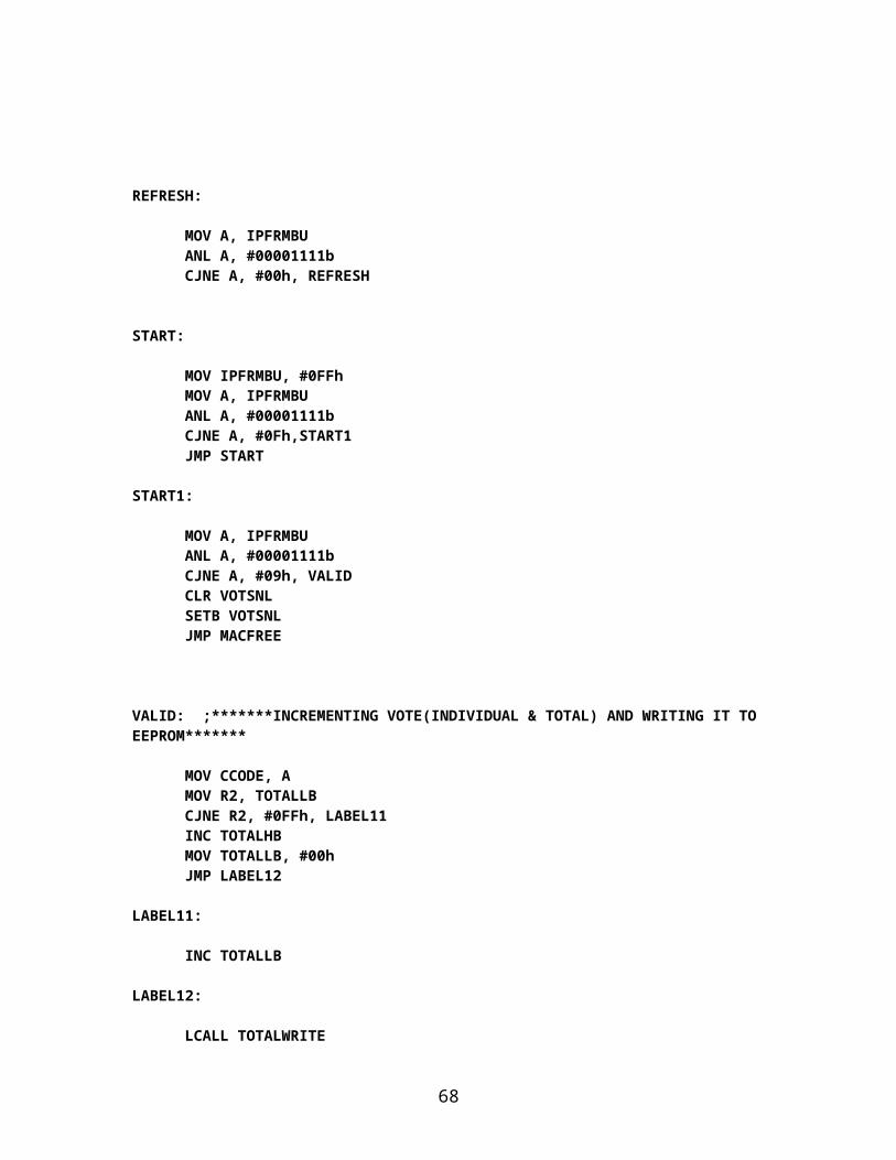
VOTEREAD:
MOV R3, #10hMOV R0, #32hMOV MEMORY, #02h
LABEL:
MOV A, #WTCMD CALL OUTS MOV A,MEMORY CALL OUT CALL CREAD MOV A,R1 MOV @R0,AINC R0INC MEMORY DJNZ R3,LABELRET
;*************************** ROUTINE 8: INITIALIZING EEPROM LOCATIONS WHERE TOTAL COUNT HAS TO BE SAVED, BY ZERO***************************************
MEMORYINIT:
MOV A,#WTCMD CALL OUTS MOV A,#84H CALL OUT MOV A,#00h CALL OUT CALL STOP ACALL DELAY_STOPMOV A,#WTCMD CALL OUTS MOV A,#85H CALL OUT MOV A,#00h CALL OUT CALL STOP ACALL DELAY_STOPRET
;************************** ROUTINE 9: INITIALIZING EEPROM LOCATIONS WHERE INDIVIDUAL COUNT HAS TO BE SAVED, BY ZERO*********************************
MEMINIT:
68
MOV R3,#10hMOV MEMORY,#02h
LABELM:
MOV A,#WTCMD CALL OUTS MOV A,MEMORY CALL OUT MOV A,#00h CALL OUT CALL STOP ACALL DELAY_STOPINC MEMORY DJNZ R3,LABELMRET
;*******************EEPROM ROUTINES COMMON TO ALL************************
OUTS:
MOV R2,#8 SETB SDA1 SETB SCL1 CLR SDA1 CLR SCL1
OTSLP:
RLC A JNC BITLSSETB SDA1 JMP OTSL1
BITLS:
CLR SDA1
OTSL1:
SETB SCL1 CLR SCL1 DJNZ R2,OTSLP SETB SDA1 SETB SCL1 CLR SCL1RET
OUT:
69
MOV R2,#8
OTLP:
RLC A JNC BITL SETB SDA1 JMP OTL1
BITL:
CLR SDA1
OTL1:
SETB SCL1 CLR SCL1 DJNZ R2,OTLPSETB SDA1SETB SCL1CLR SCL1RET
STOP:
CLR SDA1 SETB SCL1 SETB SDA1 RET
CREAD:
MOV A,#RDCMD CALL OUTS CALL IN MOV R1,A CALL STOP RET
IN:
MOV R2,#8 SETB SDA1
INLP:
CLR SCL1 SETB SCL1 CLR C JNB SDA1,INL1 CPL C
INL1:
RLC A DJNZ R2,INLP CLR SCL1 RET
70
ACKTST:
MOV A,#WTCMD MOV R2,#8
CLR SDA1 CLR SCL1
AKTLP:
RLC A JNC AKTLSSETB SDA1 JMP AKTL1
AKTLS:
CLR SDA1
AKTL1:
SETB SCL1 CLR SCL1 DJNZ R2,AKTLP SETB SDA1 SETB SCL1 JNB SDA1,EXIT JMP ACKTST
EXIT:
CLR SCL1 CLR SDA1 SETB SCL1 SETB SDA1 RET
;**************TERMINATING WRITE PROCESS***********************************
DELAY_STOP: MOV TMOD,#00000001BMOV TH0,#50H MOV TL0,#00HSETB TR0SAC:JNB TF0,SACCLR TR0CLR TF0RET
71
;******************EEPROM ROUTINES COMMON TO ALL, END HERE********************
END
72
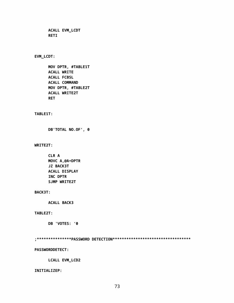
7. PROJECT METHODOLOGY
7.1 Components:
7.1(a) Ballot Unit:
Component Name Quantity 1. Microcontroller Section
Microcontroller IC (AT89S52) 1Crystal Oscillator (11.0592 MHz) 2Ceramic Capacitor (30pF) 2Ceramic Connector (104pF) 1Electrolytic Capacitor (1000uF) 1Electrolytic Capacitor (10uF) 2Transistor (L78MOSA3V) 1Resistor Array (10Kohm) 1Resistor (1Kohm) 1Diodes 4Port Connectors 4
2. Candidate PanelPush-to-On Switches 8LED 8Resistors (1Kohm) 8
3. Votecast PanelLED 8Resistors (1Kohm) 8
4. Machine Ready LEDLED 1Resistor (1Kohm) 1
5. Buzzer SectionIC (PC817) 1PNP Transistor (BC557) 1Resistor (10Kohm) 1Resistor (1Kohm) 2Buzzer 1
73

7.1(b) Control Unit:
Component Name Quantity 1. Microcontroller Section
Microcontroller IC (AT89S52) 1Crystal Oscillator (11.0592 MHz) 2Ceramic Capacitor (30pF) 2Ceramic Connector (104pF) 1Electrolytic Capacitor (1000uF) 1Electrolytic Capacitor (10uF) 2Transistor (L78MOSA3V) 1Resistor Array (10Kohm) 1Resistor (1Kohm) 1Diodes 4Port Connectors 4
2. Hex Keypad Push-to-On Switches 16
Resistors (1Kohm) 8
3. LCD PANELLCD (16X2 characters) 1 Resistors (1Kohm) 2
4. Status LEDLED 1Resistor (1Kohm) 1
5. Ballot Button Push-to-On Switch 1LED 1Resistor (1Kohm) 1
6. Result Button Push-to-On Switch 1LED 1Resistor (1Kohm) 1
7. Total Button Push-to-On Switch 1LED 1Resistor (1Kohm) 1
74
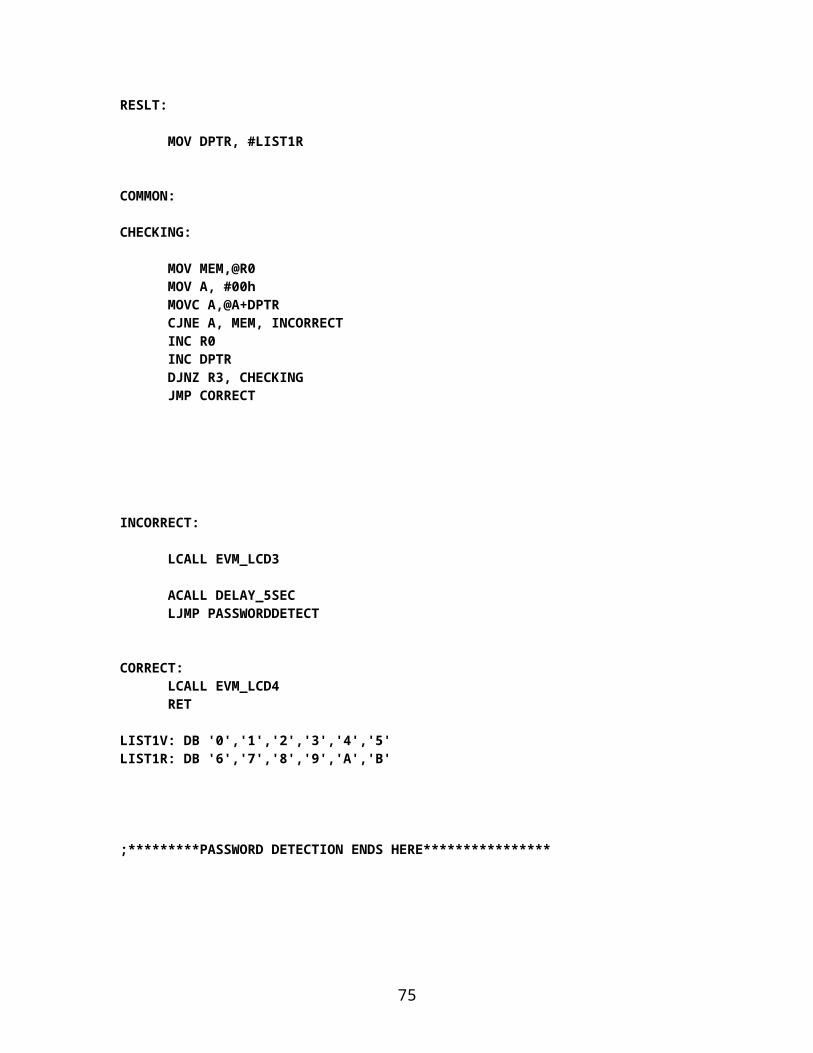
8. Close Button Push-to-On Switch 1LED 1Resistor (1Kohm) 1
9. EEPROM SectionEEPROM IC (AT24C08) 1Resistor (1Kohm) 2
7.2 Softwares used:
1. Keil uVision3.2. SPIPGM37.
7.3 Equipments used:
1. Soldering iron, solder, flux. 2. Personal computer.3. DB25 connector.
7.4 Procedure of building the Electronic Voting Machine
Step 1: Block diagram and layout of the proposed system is designed and finalized.(Refer to Figure 6.1 )
Step 2: All the components and software platform to be used are selected which are also mentioned above.
Step 3: All the hardware components are soldered on their respective printed circuit boards with the help of soldering ion, solder and flux according to the hardware schematic shown in the Figure 7.1, Figure 7.2 and Figure 7.3
Step 4: The logic flow of the whole system is decided and accordingly flow-charts are being created shown in the Figure 6.3 and Figure 6.5
Step 5: According to the flow-charts drawn, code/program of the proposed system is developed using assembly language with the help of software platform (Keil u vision3).the coding could be seen in section 6.1(d) and section 6.2(d).
75

Step 6: The hex code of the program being created by the software platform is burnt into the flash code memory of our microcontroller IC.
Step 7: Testing is done at various levels to finalize the appropriate program for the most proper working of the system
7.5 Using the Electronic Voting Machine
1. When power of control unit is turned on, the CU reads the status of the machine form the EPROM into the accumulator.
2. On the basis of the status read from accumulator the CU goes into one of the two modes (A) Voting mode.(B) Result mode.
3. Let us assume that machine enters the voting mode.
(A) Voting Modexiv. Now the LCD displays “VOTING MODE STARTING…..”.xv. After a few seconds LCD displays “ENTER PASSWORD
(SIX CHARACTER LONG)”xvi. Now the 6-character password needs to be entered through “hexadecimal
keypad”.xvii. As the user presses the first key, LCD displays “* ”.
As the user presses the second key, LCD displays “** ”.As the user presses the third key, LCD displays “*** ”.As the user presses the fourth key, LCD displays “**** ”.As the user presses the fifth key, LCD displays “***** ”As the user presses the sixth key, LCD displays “******”.
xviii. After that when complete password is entered into the RAM of CU, it is compared with the actual password stored in the ROM memory of CU.
xix. If the password is correct, LCD displays “PASSWORD ACCEPTED PROCEED AHEAD……”.
xx. If the password is wrong, LCD displays “WRONG PASSWORD”, after that CU moves to step ii again.
xxi. The “status LED” on the CU glows to indicate it is ready for polling procedure.xxii. Machine waits for the “Ballot Button” to be pressed. As soon as the ballet button
is pressed, the CU sends a “READY SIGNAL” which is active low.xxiii. Now the CU waits for the four-bit code from ballot unit.xxiv. After getting “READY SIGNAL”, ballot unit glows its “MACHINE READY
LED” indicating that the machine is ready to accept a new vote from its candidate panel.
76
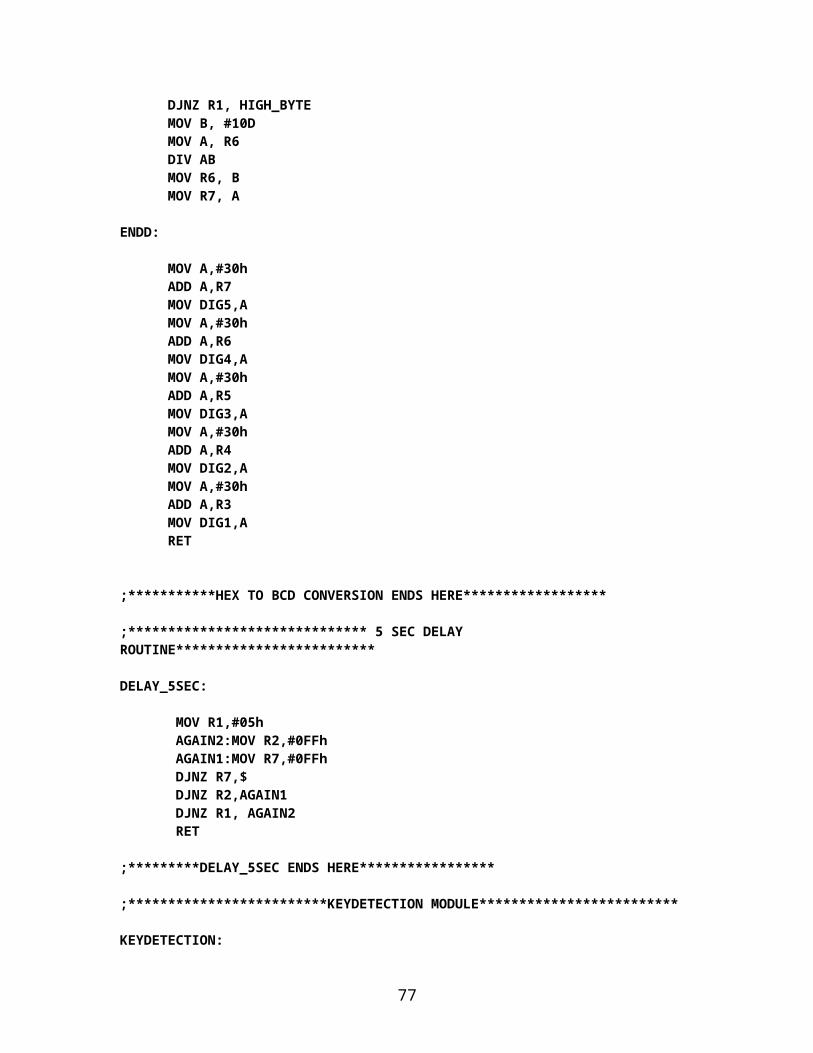
xxv. Once the voter presses the button corresponding to the candidate of her/his choice, a four-bit code is generated and sent to the control unit.
xxvi. “MACHINE READY LED” is turned off by the ballot unit after Accepting the vote and the ballot unit waits for the “vote signal” to become low from control unit,
xxvii. On the basis of the code received by the CU, the memory location where the selected candidate’s vote count is stored is accessed and count is incremented. Simultaneously total count is also incremented.
xxviii. After that, CU sends a LOW “vote signal” to ballot unit to turn on “VOTE CAST LED” and generate buzzer beep, after sometime, “vote signal” is made HIGH.
xxix. After “VOTE SIGNAL” goes low, the ballet unit glows the “VOTE CAST LED” on the vote cast panel for the corresponding candidate whose vote is being cast.
xxx. At this time, the buzzer also generates a beep sound. This indicates to the voter that her/his vote has been processed.
xxxi.xxxii. Then program control goes to step viii.
xxxiii. After the voting is complete, i.e. the last voter has cast his/her vote or in case of booth capture, the “CLOSE” button is pressed.
CLOSE(Interrupt Controlled Button)
1. Whenever the “CLOSE” button is pressed, an interrupt is generated and an ISR is called.
2. The value of status is written in EEPROM to make the machine enter into the result mode, when the machine is powered on next time.
3. The machine goes on “POWER DOWN” mode.
TOTAL(Interrupt controlled button)
1. Whenever, the “TOTAL” button is pressed, an interrupt is generated and an Interrupt service routine is called.
2. This ISR retrieves the total vote count from EEPROM and displays it on the LCD.
(B) Result Modexi. Now the LCD displays “RESULT MODE STRARTING…..”.
xii. After a few seconds LCD displays “ENTER PASSWORD SIX CHARACTER LONG”
77
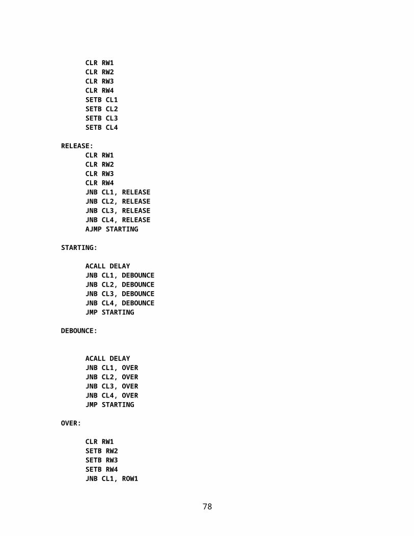
xiii. Now the 6-character password needs to be entered through “hexadecimal keypad”.
xiv. As the user presses the first key, LCD displays “* ”.As the user presses the second key, LCD displays “** ”.As the user presses the third key, LCD displays “*** ”.As the user presses the fourth key, LCD displays “**** ”.As the user presses the fifth key, LCD displays “***** ”As the user presses the sixth key, LCD displays “******”.
xv. After that when complete password is entered into the RAM of CU it is compared with the actual password stored in the ROM memory of CU.
xvi. If the password is correct, LCD displays “PASSWORD ACCEPTED PROCEED AHEAD”.
xvii. If the password is wrong, LCD displays “WRONG PASSWORD”, After that CU moves to step ii again.
xviii. The LCD displays “CANDIDATE #1 VOTES: ______”.xix. Now it waits for the result button to be pressed, the result of next candidate is
displayed.xx. Step ix is repeated to get result of all the candidates.
78
7.6 Hardware Schematic
7.6(a) Ballot Unit:
79

Figure 7.1 Hardware schematic of ballot unit
7.6(b) Control Unit:
Figure 7.2 Hardware schematic of control unit
80

7.6(c) Complete EVM system:
81
Figure 7.3 Hardware schematic of complete EVM system
8. RESULT AND CONCLUSION
The EVM consists of a control unit (CU) and ballot unit (BU), both the units are working independently and in collaboration with each other as well.
The CU is accepting password in voting mode and is responding accordingly. In voting mode, CU communicates with BU in order to exchange various signals. CU is counting the votes for individual candidate (8 in number) and total number of
votes cast can be checked at anytime. In case of booth capture, the machine can be sealed in such a way that, when powered
again, it automatically opens in result mode. In result mode, the CU is again following the same password detection routine as in
case of voting mode. In result mode, the CU displays the votes of individual candidate, in consecutive
order, whenever the “Result Button” is pressed. The total number of votes can be checked in result mode in the same way as in voting
mode.
In total, the complete system (including all the hardware components and software routines) is working as per the initial specifications and requirements of our project. Because of the creative nature of the design, and due to lack of time, some features could not be fine-tuned and are not working properly. So certain aspects of the system can be modified as operational experience is gained with it. As the users work with the system, they develop various new ideas for the development and enhancement of the project.
82
9. APPLICATIONS
Fast track voting which could be used in small scale elections, like resident welfare association, “panchayat” level election and other society level elections.
It could also be used to conduct opinion polls during annual share holders meeting.
It could also be used to conduct general assembly elections where number of candidates are less than or equal to eight in the current situation.
83
10. FUTURE SCOPE
Number of candidates could be increased by using other microcontroller or an 8255 IC.
It could be interfaced with printer to get the hard copy of the result almost instantly from the machine itself.
It could also be interfaced with the personal computer and result could be stored in the central server and its backup could be taken on the other backend servers.
Again, once the result is on the server it could be relayed on the network to various offices of the election conducting authority. Thus our project could make the result available any corner of the world in a matter of seconds
84
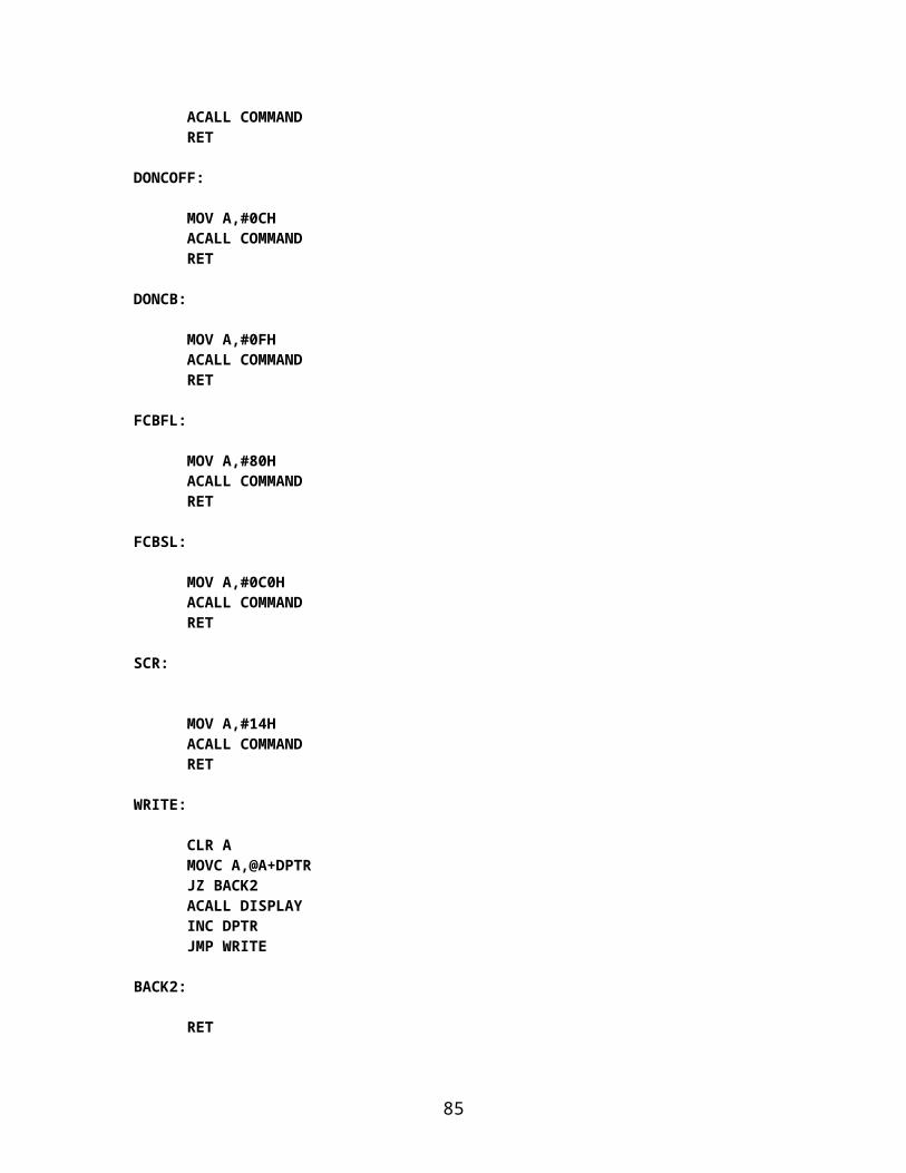
11. REFRENCES AND BIBLOGRAPHY
Muhammad Ali Mazidi , Janice Gillispie Mazidi, Rolin D. Mckinlay.Second edition, “THE 8051 MICROCONTROLLER AND EMBEDDED SYSTEM”
K. J. Ayala. Third edition, “The 8051 MICROCONTROLLER”
General information about electronic voting machinewww.eci.gov.inwww.eci.gov.in/faq/evm.aspwww.eci.gov.in/Audio_VideoClips/presentation/EVM.pptwww.rajasthan.net/election/guide/evm.htmwww.indian-elections.com/electoralsystem/electric votingmachine .html
Tutorial on microcontroller: www.8051projects.net/microcontroller_tutorials/
Tutorial on LCD: www.8051projects.net/lcd-interfacing/
85
Related Documents