The Electronic Latch is an 8-pin electronic switching component developed as a part of the LOGIC Series by VIVISUN. The Electronic Latch replaces traditional magnetic or solenoid latching switches and can be integrated in a traditional 4-pole switch housing, creating a LOGIC Body (LB), or can be included in a stand-alone LOGIC Module (LM) for use behind the panel. The Electronic Latch can also be combined with electromechanical switches and other LOGIC Series components to create a custom configuration that uniquely addresses the designer’s specific functional requirements. The Electronic Latch is designed and tested in accordance with MIL-PRF-22885 and DO-160. Electronic Latch • Set, Reset, and Toggle Capabilities • Local, Remote, and Lockout Control • Simplifies Complex Circuit Designs • Replaces Magnetic or Solenoid Switches • Built-in Blink Circuitry • Powers up in either RESET (EL1) or SET with BLINK active (EL2) • Resets to known or safe position with loss of power cycle • Approved, witnessed and conformed to RTCA/DO-160 High Capacity LOGIC Body as shown contains Electronic Latch, single switch pole and 4-pin LOGIC component LOGIC Module as shown contains Electronic Latch and 4-pin LOGIC components Data Sheet: DS-EL1-12 LOGIC Component Technology ELECTRONIC LATCH ELECTRONIC SWITCHING www.appliedavionics.com

Welcome message from author
This document is posted to help you gain knowledge. Please leave a comment to let me know what you think about it! Share it to your friends and learn new things together.
Transcript
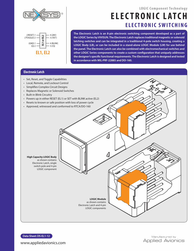
The Electronic Latch is an 8-pin electronic switching component developed as a part of the LOGIC Series by VIVISUN. The Electronic Latch replaces traditional magnetic or solenoid latching switches and can be integrated in a traditional 4-pole switch housing, creating a LOGIC Body (LB), or can be included in a stand-alone LOGIC Module (LM) for use behind the panel. The Electronic Latch can also be combined with electromechanical switches and other LOGIC Series components to create a custom configuration that uniquely addresses the designer’s specific functional requirements. The Electronic Latch is designed and tested in accordance with MIL-PRF-22885 and DO-160.
Electronic Latch
• Set, Reset, and Toggle Capabilities• Local, Remote, and Lockout Control• Simplifies Complex Circuit Designs• Replaces Magnetic or Solenoid Switches• Built-in Blink Circuitry• Powers up in either RESET (EL1) or SET with BLINK active (EL2)• Resets to known or safe position with loss of power cycle• Approved, witnessed and conformed to RTCA/DO-160
High Capacity LOGIC Body as shown contains
Electronic Latch, single switch pole and 4-pin
LOGIC component
LOGIC Module as shown contains
Electronic Latch and 4-pin LOGIC components
Data Sheet: DS-EL1-12
LO G I C C o m p o n e n t Te c h n o l o g y
E L E C T R O N I C L AT C HE L E C T R O N I C S W I T C H I N G
www.appliedavionics.com
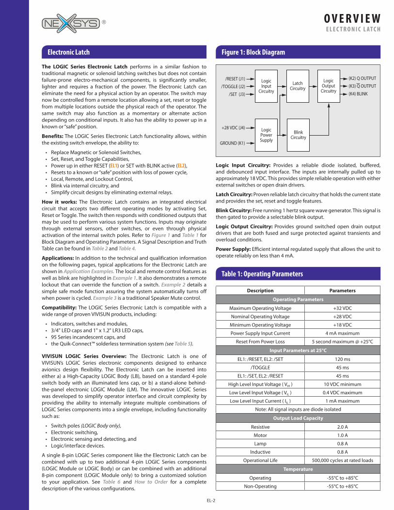
Electronic Latch Figure 1: Block Diagram
Table 1: Operating Parameters
The LOGIC Series Electronic Latch performs in a similar fashion to traditional magnetic or solenoid latching switches but does not contain failure-prone electro-mechanical components, is significantly smaller, lighter and requires a fraction of the power. The Electronic Latch can eliminate the need for a physical action by an operator. The switch may now be controlled from a remote location allowing a set, reset or toggle from multiple locations outside the physical reach of the operator. The same switch may also function as a momentary or alternate action depending on conditional inputs. It also has the ability to power up in a known or “safe” position.
Benefits: The LOGIC Series Electronic Latch functionality allows, within the existing switch envelope, the ability to:
• Replace Magnetic or Solenoid Switches,• Set, Reset, and Toggle Capabilities,• Power up in either RESET (EL1) or SET with BLINK active (EL2),• Resets to a known or “safe” position with loss of power cycle,• Local, Remote, and Lockout Control,• Blink via internal circuitry, and• Simplify circuit designs by eliminating external relays.
How it works: The Electronic Latch contains an integrated electrical circuit that accepts two different operating modes by activating Set, Reset or Toggle. The switch then responds with conditioned outputs that may be used to perform various system functions. Inputs may originate through external sensors, other switches, or even through physical activation of the internal switch poles. Refer to Figure 1 and Table 1 for Block Diagram and Operating Parameters. A Signal Description and Truth Table can be found in Table 2 and Table 4.
Applications: In addition to the technical and qualification information on the following pages, typical applications for the Electronic Latch are shown in Application Examples. The local and remote control features as well as blink are highlighted in Example 1. It also demonstrates a remote lockout that can override the function of a switch. Example 2 details a simple safe mode function assuring the system automatically turns off when power is cycled. Example 3 is a traditional Speaker Mute control.
Compatibility: The LOGIC Series Electronic Latch is compatible with a wide range of proven VIVISUN products, including:
• Indicators, switches and modules,• 3/4" LED caps and 1" x 1.2" LR3 LED caps,• 95 Series incandescent caps, and• the Quik-Connect™ solderless termination system (see Table 5).
VIVISUN LOGIC Series Overview: The Electronic Latch is one of VIVISUN’s LOGIC Series electronic components designed to enhance avionics design flexibility. The Electronic Latch can be inserted into either a) a High-Capacity LOGIC Body (LB), based on a standard 4-pole switch body with an illuminated lens cap, or b) a stand-alone behind-the-panel electronic LOGIC Module (LM). The innovative LOGIC Series was developed to simplify operator interface and circuit complexity by providing the ability to internally integrate multiple combinations of LOGIC Series components into a single envelope, including functionality such as:
• Switch poles (LOGIC Body only),• Electronic switching,• Electronic sensing and detecting, and• Logic/interface devices.
A single 8-pin LOGIC Series component like the Electronic Latch can be combined with up to two additional 4-pin LOGIC Series components (LOGIC Module or LOGIC Body) or can be combined with an additional 8-pin component (LOGIC Module only) to bring a customized solution to your application. See Table 6 and How to Order for a complete description of the various configurations.
Logic Input Circuitry: Provides a reliable diode isolated, buffered, and debounced input interface. The inputs are internally pulled up to approximately 18 VDC. This provides simple reliable operation with either external switches or open drain drivers.
Latch Circuitry: Proven reliable latch circuitry that holds the current state and provides the set, reset and toggle features.
Blink Circuitry: Free running 1 hertz square wave generator. This signal is then gated to provide a selectable blink output.
Logic Output Circuitry: Provides ground switched open drain output drivers that are both fused and surge protected against transients and overload conditions.
Power Supply: Efficient internal regulated supply that allows the unit to operate reliably on less than 4 mA.
Description Parameters
Operating Parameters
Maximum Operating Voltage +32 VDC
Nominal Operating Voltage +28 VDC
Minimum Operating Voltage +18 VDC
Power Supply Input Current 4 mA maximum
Reset From Power Loss 5 second maximum @ +25°C
Input Parameters at 25°C
EL1: /RESET, EL2: /SET 120 ms
/TOGGLE 45 ms
EL1: /SET, EL2: /RESET 45 ms
High Level Input Voltage ( VIH ) 10 VDC minimum
Low Level Input Voltage ( VIL ) 0.4 VDC maximum
Low Level Input Current ( IIL ) 1 mA maximum
Note: All signal inputs are diode isolated
Output Load Capacity
Resistive 2.0 A
Motor 1.0 A
Lamp 0.8 A
lnductive 0.8 A
Operational Life 500,000 cycles at rated loads
Temperature
Operating -55°C to +85°C
Non-Operating -55°C to +85°C
O V E R V I E WE L E C T R O N I C L AT C H
EL-2
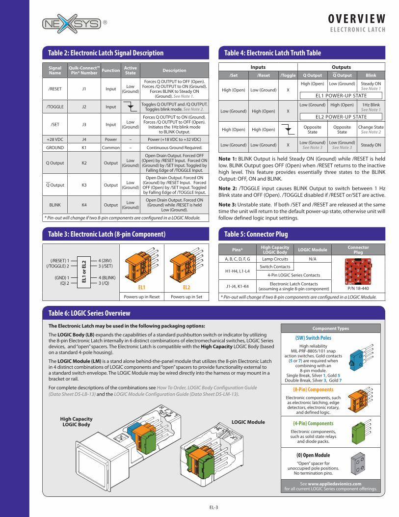
Table 2: Electronic Latch Signal Description Table 4: Electronic Latch Truth Table
Table 3: Electronic Latch (8-pin Component) Table 5: Connector Plug
Inputs Outputs/Set /Reset /Toggle Q Output
—Q Output Blink
High (Open) Low (Ground) XHigh (Open) Low (Ground) Steady ON
See Note 1
Low (Ground) High (Open) XLow (Ground) High (Open) 1Hz Blink
See Note 1
High (Open) High (Open) Opposite State
Opposite State
Change State See Note 2
Low (Ground) Low (Ground) X Low (Ground) See Note 3
Low (Ground) See Note 3 Steady ON
EL1 POWER-UP STATE
EL2 POWER-UP STATE
Signal Name
Quik-Connect™ Pin* Number Function Active
State Description
/RESET J1 Input Low (Ground)
Forces Q OUTPUT to OFF (Open). Forces /Q OUTPUT to ON (Ground).
Forces BLINK to Steady ON (Ground). See Note 1.
/TOGGLE J2 Input Toggles Q OUTPUT and /Q OUTPUT. Toggles blink mode. See Note 2.
/SET J3 Input Low (Ground)
Forces Q OUTPUT to ON (Ground). Forces /Q OUTPUT to OFF (Open).
Initiates the 1Hz blink mode to BLINK Output.
+28 VDC J4 Power – Power (+18 VDC to +32 VDC)
GROUND K1 Common – Continuous Ground Required.
Q Output K2 Output Low (Ground)
Open Drain Output. Forced OFF (Open) by /RESET Input. Forced ON (Ground) by /SET Input. Toggled by
Falling Edge of /TOGGLE Input.
—Q Output K3 Output Low
(Ground)
Open Drain Output. Forced ON (Ground) by /RESET Input. Forced OFF (Open) by /SET Input. Toggled by Falling Edge of /TOGGLE Input.
BLINK K4 Output Low (Ground)
Open Drain Output. Forced ON (Ground) while /RESET is held
Low (Ground).
* Pin-out will change if two 8-pin components are configured in a LOGIC Module.
Note 1: BLINK Output is held Steady ON (Ground) while /RESET is held low. BLINK Output goes OFF (Open) when /RESET returns to the inactive high level. This feature provides essentially three states to the BLINK Output: OFF, ON and BLINK.
Note 2: /TOGGLE input causes BLINK Output to switch between 1 Hz Blink state and OFF (Open). /TOGGLE disabled if /RESET or/SET are active.
Note 3: Unstable state. If both /SET and /RESET are released at the same time the unit will return to the default power-up state, otherwise unit will follow defined logic input settings.
EL1
EL2
Powers up in Reset Powers up in Set
Pins* High Capacity LOGIC Body LOGIC Module Connector
PlugA, B, C, D, F, G Lamp Circuits N/A
P/N 18-440
H1-H4, L1-L4Switch Contacts
4-Pin LOGIC Series Contacts
J1-J4, K1-K4 Electronic Latch Contacts (assuming a single 8-pin component)
* Pin-out will change if two 8-pin components are configured in a LOGIC Module.
Table 6: LOGIC Series Overview
The Electronic Latch may be used in the following packaging options:
The LOGIC Body (LB) expands the capabilities of a standard pushbutton switch or indicator by utilizing the 8-pin Electronic Latch internally in 6 distinct combinations of electromechanical switches, LOGIC Series devices, and “open” spacers. The Electronic Latch is compatible with the High Capacity LOGIC Body (based on a standard 4-pole housing).
The LOGIC Module (LM) is a stand alone behind-the-panel module that utilizes the 8-pin Electronic Latch in 4 distinct combinations of LOGIC components and “open” spacers to provide functionality external to a standard switch envelope. The LOGIC Module may be wired directly into the harness or may mount in a bracket or rail.
For complete descriptions of the combinations see How To Order, LOGIC Body Configuration Guide (Data Sheet DS-LB-13) and the LOGIC Module Configuration Guide (Data Sheet DS-LM-13).
Component Types
{SW} Switch PolesHigh reliability
MIL-PRF-8805/101 snap action switches. Gold contacts
(5 or 7) are required when combining with an
8-pin module. Single Break, Silver 1, Gold 5
Double Break, Silver 3, Gold 7
{8-Pin} ComponentsElectronic components, such as electronic latching, edge detectors, electronic rotary,
and defined logic.
{4-Pin} ComponentsElectronic components, such as solid state relays
and diode packs.
(0) Open Module“Open” spacer for
unoccupied pole positions. No termination pins.
See www.appliedavionics.com for all current LOGIC Series component offerings.
LOGIC ModuleHigh Capacity LOGIC Body
O V E R V I E WE L E C T R O N I C L AT C H
EL-3
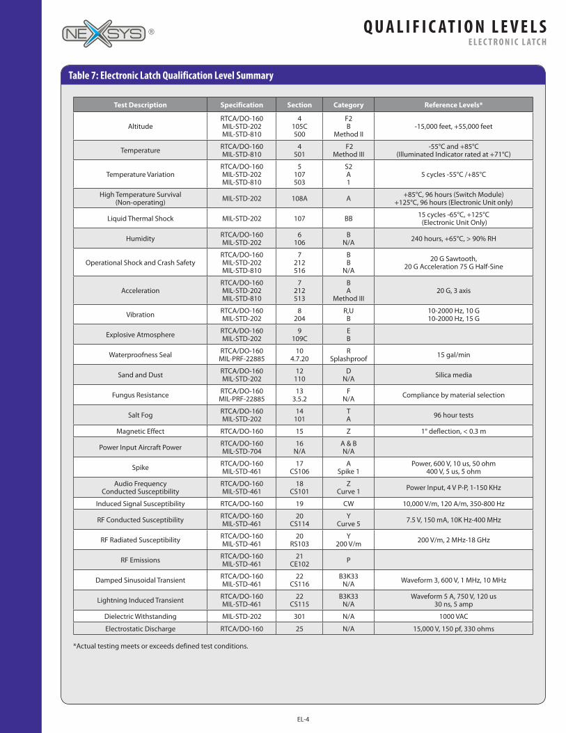
Table 7: Electronic Latch Qualification Level Summary
Test Description Specification Section Category Reference Levels*
AltitudeRTCA/DO-160 MIL-STD-202 MIL-STD-810
4 105C 500
F2 B
Method II-15,000 feet, +55,000 feet
Temperature RTCA/DO-160 MIL-STD-810
4 501
F2 Method III
-55°C and +85°C (Illuminated Indicator rated at +71°C)
Temperature VariationRTCA/DO-160 MIL-STD-202 MIL-STD-810
5 107 503
S2 A 1
5 cycles -55°C /+85°C
High Temperature Survival (Non-operating) MIL-STD-202 108A A +85°C, 96 hours (Switch Module)
+125°C, 96 hours (Electronic Unit only)
Liquid Thermal Shock MIL-STD-202 107 BB 15 cycles -65°C, +125°C (Electronic Unit Only)
Humidity RTCA/DO-160 MIL-STD-202
6 106
B N/A 240 hours, +65°C, > 90% RH
Operational Shock and Crash SafetyRTCA/DO-160 MIL-STD-202 MIL-STD-810
7 212 516
B B
N/A
20 G Sawtooth, 20 G Acceleration 75 G Half-Sine
AccelerationRTCA/DO-160 MIL-STD-202 MIL-STD-810
7 212 513
B A
Method III20 G, 3 axis
Vibration RTCA/DO-160 MIL-STD-202
8 204
R,U B
10-2000 Hz, 10 G 10-2000 Hz, 15 G
Explosive Atmosphere RTCA/DO-160 MIL-STD-202
9 109C
E B
Waterproofness Seal RTCA/DO-160 MIL-PRF-22885
10 4.7.20
R Splashproof 15 gal/min
Sand and Dust RTCA/DO-160 MIL-STD-202
12 110
D N/A Silica media
Fungus Resistance RTCA/DO-160 MIL-PRF-22885
13 3.5.2
F N/A Compliance by material selection
Salt Fog RTCA/DO-160 MIL-STD-202
14 101
T A 96 hour tests
Magnetic Effect RTCA/DO-160 15 Z 1° deflection, < 0.3 m
Power Input Aircraft Power RTCA/DO-160 MIL-STD-704
16 N/A
A & B N/A
Spike RTCA/DO-160 MIL-STD-461
17 CS106
A Spike 1
Power, 600 V, 10 us, 50 ohm 400 V, 5 us, 5 ohm
Audio Frequency Conducted Susceptibility
RTCA/DO-160 MIL-STD-461
18 CS101
Z Curve 1 Power Input, 4 V P-P, 1-150 KHz
Induced Signal Susceptibility RTCA/DO-160 19 CW 10,000 V/m, 120 A/m, 350-800 Hz
RF Conducted Susceptibility RTCA/DO-160 MIL-STD-461
20 CS114
Y Curve 5 7.5 V, 150 mA, 10K Hz-400 MHz
RF Radiated Susceptibility RTCA/DO-160 MIL-STD-461
20 RS103
Y 200 V/m 200 V/m, 2 MHz-18 GHz
RF Emissions RTCA/DO-160 MIL-STD-461
21 CE102 P
Damped Sinusoidal Transient RTCA/DO-160 MIL-STD-461
22 CS116
B3K33 N/A Waveform 3, 600 V, 1 MHz, 10 MHz
Lightning Induced Transient RTCA/DO-160 MIL-STD-461
22 CS115
B3K33 N/A
Waveform 5 A, 750 V, 120 us 30 ns, 5 amp
Dielectric Withstanding MIL-STD-202 301 N/A 1000 VAC
Electrostatic Discharge RTCA/DO-160 25 N/A 15,000 V, 150 pf, 330 ohms
*Actual testing meets or exceeds defined test conditions.
EL-4
Q U A L I F I C AT I O N L E V E L SE L E C T R O N I C L AT C H
Application Examples
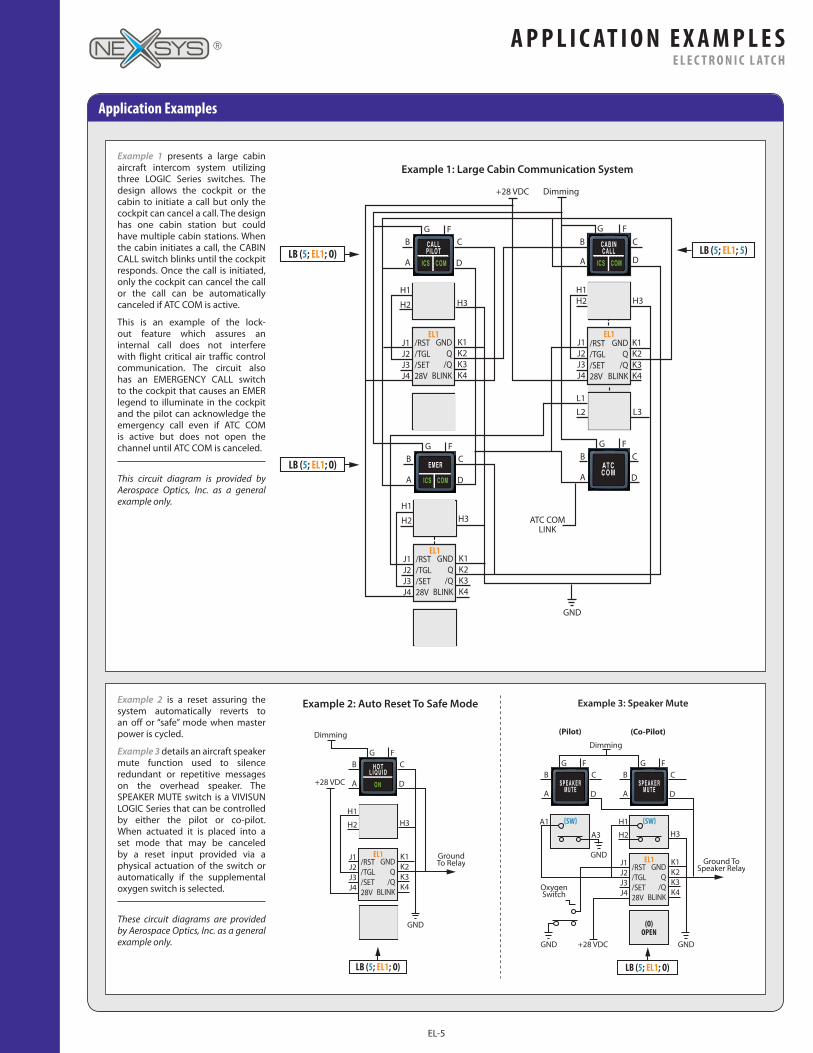
Example 1 presents a large cabin aircraft intercom system utilizing three LOGIC Series switches. The design allows the cockpit or the cabin to initiate a call but only the cockpit can cancel a call. The design has one cabin station but could have multiple cabin stations. When the cabin initiates a call, the CABIN CALL switch blinks until the cockpit responds. Once the call is initiated, only the cockpit can cancel the call or the call can be automatically canceled if ATC COM is active.
This is an example of the lock-out feature which assures an internal call does not interfere with flight critical air traffic control communication. The circuit also has an EMERGENCY CALL switch to the cockpit that causes an EMER legend to illuminate in the cockpit and the pilot can acknowledge the emergency call even if ATC COM is active but does not open the channel until ATC COM is canceled.
This circuit diagram is provided by Aerospace Optics, Inc. as a general example only.
Example 2 is a reset assuring the system automatically reverts to an off or “safe” mode when master power is cycled.
Example 3 details an aircraft speaker mute function used to silence redundant or repetitive messages on the overhead speaker. The SPEAKER MUTE switch is a VIVISUN LOGIC Series that can be controlled by either the pilot or co-pilot. When actuated it is placed into a set mode that may be canceled by a reset input provided via a physical actuation of the switch or automatically if the supplemental oxygen switch is selected.
These circuit diagrams are provided by Aerospace Optics, Inc. as a general example only.
Example 1: Large Cabin Communication System
Example 2: Auto Reset To Safe Mode Example 3: Speaker Mute
EL-5
A P P L I C AT I O N E X A M P L E SE L E C T R O N I C L AT C H
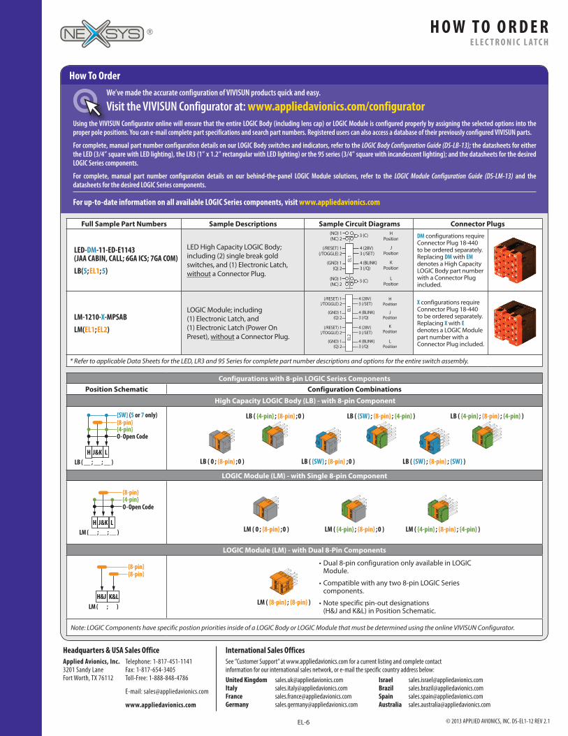
How To OrderWe’ve made the accurate configuration of VIVISUN products quick and easy.
Visit the VIVISUN Configurator at: www.appliedavionics.com/configuratorUsing the VIVISUN Configurator online will ensure that the entire LOGIC Body (including lens cap) or LOGIC Module is configured properly by assigning the selected options into the proper pole positions. You can e-mail complete part specifications and search part numbers. Registered users can also access a database of their previously configured VIVISUN parts.
For complete, manual part number configuration details on our LOGIC Body switches and indicators, refer to the LOGIC Body Configuration Guide (DS-LB-13); the datasheets for either the LED (3/4” square with LED lighting), the LR3 (1” x 1.2” rectangular with LED lighting) or the 95 series (3/4” square with incandescent lighting); and the datasheets for the desired LOGIC Series components.
For complete, manual part number configuration details on our behind-the-panel LOGIC Module solutions, refer to the LOGIC Module Configuration Guide (DS-LM-13) and the datasheets for the desired LOGIC Series components.
For up-to-date information on all available LOGIC Series components, visit www.appliedavionics.com
Configurations with 8-pin LOGIC Series ComponentsPosition Schematic Configuration Combinations
High Capacity LOGIC Body (LB) - with 8-pin Component
LB ( __ ; __ ; __ )LJ & KH
{SW} (5 or 7 only) {8-pin}{4-pin}O- Open Code
LB ( 0 ; {8-pin} ; 0 ) LB ( {SW} ; {8-pin} ; {SW} ) LB ( {SW} ; {8-pin} ; 0 )
LB ( {4-pin} ; {8-pin} ; 0 ) LB ( {4-pin} ; {8-pin} ; {4-pin} ) LB ( {SW} ; {8-pin} ; {4-pin} )
LOGIC Module (LM) - with Single 8-pin Component
LM ( 0 ; {8-pin} ; 0 ) LM ( {4-pin} ; {8-pin} ; 0 ) LM ( {4-pin} ; {8-pin} ; {4-pin} )
LOGIC Module (LM) - with Dual 8-Pin Components
Note: LOGIC Components have specific postion priorities inside of a LOGIC Body or LOGIC Module that must be determined using the online VIVISUN Configurator.
Full Sample Part Numbers Sample Descriptions Sample Circuit Diagrams Connector Plugs
LED-DM-11-ED-E1143 (JAA CABIN, CALL; 6GA ICS; 7GA COM)LB(5; EL1; 5)
LED High Capacity LOGIC Body; including (2) single break gold switches, and (1) Electronic Latch, without a Connector Plug.
DM configurations require Connector Plug 18-440 to be ordered separately. Replacing DM with EM denotes a High Capacity LOGIC Body part number with a Connector Plug included.
LM-1210-X-MPSABLM(EL1; EL2)
LOGIC Module; including (1) Electronic Latch, and (1) Electronic Latch (Power On Preset), without a Connector Plug.
X configurations require Connector Plug 18-440 to be ordered separately. Replacing X with E denotes a LOGIC Module part number with a Connector Plug included.
* Refer to applicable Data Sheets for the LED, LR3 and 95 Series for complete part number descriptions and options for the entire switch assembly.
LM ( {8-pin} ; {8-pin} )
• Dual 8-pin configuration only available in LOGIC Module.
• Compatible with any two 8-pin LOGIC Series components.
• Note specific pin-out designations (H&J and K&L) in Position Schematic.
© 2013 APPLIED AVIONICS, INC. DS-EL1-12 REV 2.1
Headquarters & USA Sales OfficeApplied Avionics, Inc. Telephone: 1-817-451-1141 3201 Sandy Lane Fax: 1-817-654-3405 Fort Worth, TX 76112 Toll-Free: 1-888-848-4786
E-mail: [email protected]
www.appliedavionics.com
International Sales OfficesSee ”Customer Support” at www.appliedavionics.com for a current listing and complete contact information for our international sales network, or e-mail the specific country address below:
Israel Brazil Spain Australia
United Kingdom Italy France Germany
[email protected] [email protected] [email protected] [email protected]
[email protected] [email protected] [email protected] [email protected]
EL-6
H O W T O O R D E RE L E C T R O N I C L AT C H
Related Documents