Hydraulics and Hydraulic Machines Dr. M.N. Shesha Prakash, Professor, J.N.N. College of Engineering, Shimoga 1 Reaction Turbines Reaction turbines are those turbines which operate under hydraulic pressure energy and part of kinetic energy. In this case, the water reacts with the vanes as it moves through the vanes and transfers its pressure energy to the vanes so that the vanes move in turn rotating the runner on which they are mounted. The main types of reaction turbines are 1. Radially outward flow reaction turbine: This reaction turbine consist a cylindrical disc mounted on a shaft and provided with vanes around the perimeter. At inlet the water flows into the wheel at the centre and then glides through radially provided fixed guide vanes and then flows over the moving vanes. The function of the guide vanes is to direct or guide the water into the moving vanes in the correct direction and also regulate the amount of water striking the vanes. The water as it flows along the moving vanes will exert a thrust and hence a torque on the wheel thereby rotating the wheel. The water leaves the moving vanes at the outer edge. The wheel is enclosed by a water-tight casing. The water is then taken to draft tube. 2. Radially inward flow reaction turbine: The constitutional details of this turbine are similar to the outward flow turbine but for the fact that the guide vanes surround the moving vanes. This is preferred to the outward flow turbine as this turbine does not develop racing. The centrifugal force on the inward moving body of water decreases the relative velocity and thus the speed of the turbine can be controlled easily. The main component parts of a reaction turbine are: (1) Casing, (2) Guide vanes (3) Runner with vanes (4) Draft tube Casing : This is a tube of decreasing cross-sectional area with the axis of the tube being of geometric shape of volute or a spiral. The water first fills the casing and then enters the guide vanes from all

Welcome message from author
This document is posted to help you gain knowledge. Please leave a comment to let me know what you think about it! Share it to your friends and learn new things together.
Transcript

Hydraulics and Hydraulic Machines
Dr. M.N. Shesha Prakash, Professor, J .N.N. College of Engineering, Shimoga 1
Reaction TurbinesReaction turbines are those turbines which operate under hydraulic
pressure energy and part of kinetic energy. In this case, the water reacts
with the vanes as it moves through the vanes and transfers its pressure
energy to the vanes so that the vanes move in turn rotating the runner on
which they are mounted.
The main types of reaction turbines are
1. Radially outward flow reaction turbine: This reaction turbine
consist a cylindrical disc mounted on a shaft and provided with
vanes around the perimeter. At inlet the water flows into the wheel
at the centre and then glides through radially provided fixed guide
vanes and then flows over the moving vanes. The function of the
guide vanes is to direct or guide the water into the moving vanes in
the correct direction and also regulate the amount of water striking
the vanes. The water as it flows along the moving vanes will exert a
thrust and hence a torque on the wheel thereby rotating the wheel.
The water leaves the moving vanes at the outer edge. The wheel is
enclosed by a water-tight casing. The water is then taken to draft
tube.
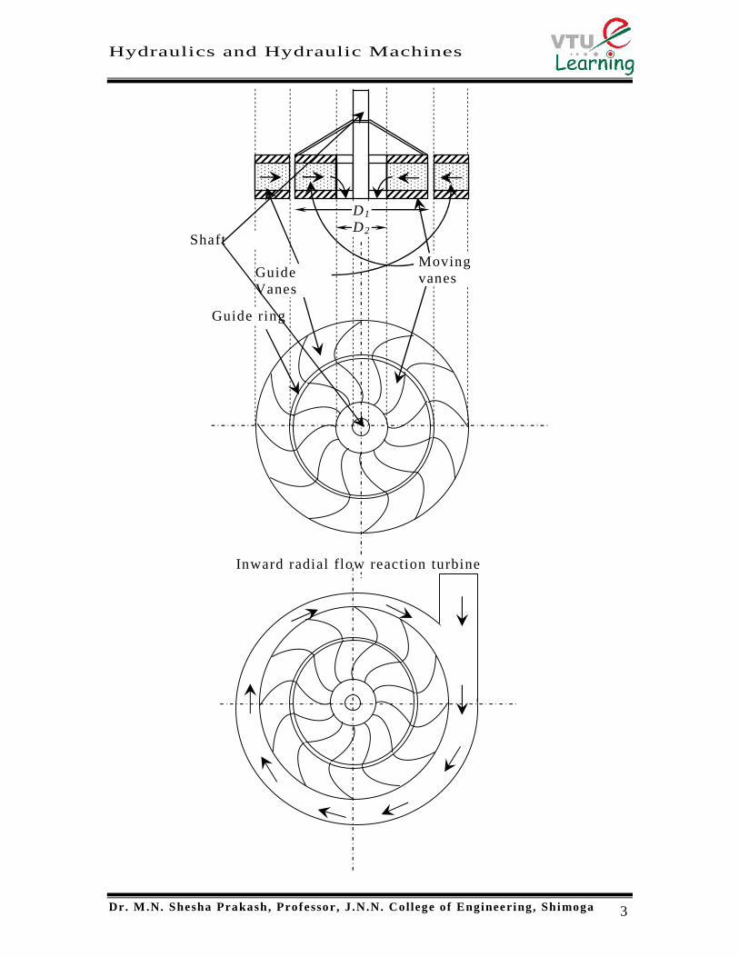
2. Radially inward flow reaction turbine: The consti tutional details of
this turbine are similar to the outward flow turbine but for the fact
that the guide vanes surround the moving vanes. This is preferred to
the outward flow turbine as this turbine does not develop racing.
The centrifugal force on the inward moving body of water decreases
the relative velocity and thus the speed of the turbine can be
controlled easily.
The main component parts of a reaction turbine are:
(1) Casing, (2) Guide vanes (3) Runner with vanes (4) Draft tube
Casing : This is a tube of decreasing cross -sectional area with the
axis of the tube being of geometric shape of volute or a spiral . The
water first fi lls the casing and then enters the guide vanes from all

Hydraulics and Hydraulic Machines
Dr. M.N. Shesha Prakash, Professor, J .N.N. College of Engineering, Shimoga 2
sides radially inwards. The decreasing cross -sectional area helps the
velocity of the entering water from all sides being kept equal. The
geometric shape helps the entering water avoiding or p reventing the
creation of eddies. .
Guide vanes : Already mentioned in the above sections.
Runner with vanes : The runner is mounted on a shaft and the blades
are fixed on the runner at equal distances. The vanes are so shaped
that the water reacting with them will pass through them thereby
passing their pressure energy to make it rotate the runner.
Draft tube : This is a divergent tube fixed at the end of the outlet of
the turbine and the other end is submerged under the water level in
the tail race. The water after working on the turbine, transfers the
pressure energy there by losing all its pressure and falling below
atmospheric pressure. The draft tube accepts this water at the upper
end and increases its pressure as the water flows through the tube
and increases more than atmospheric pressure before it reaches the
tailrace.
3. Mixed flow reaction turbine : This is a turbine wherein it is similar
to inward flow reaction turbine except that when it leaves the
moving vane, the direction of water is turned from rad ial at entry to
axial at outlet. The rest of the parts and functioning is same as that
of the inward flow reaction turbines.
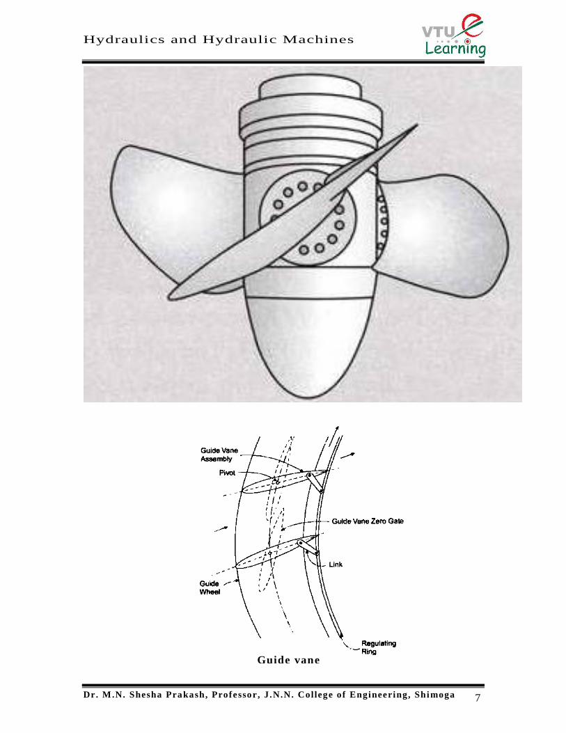
4. Axial flow reaction turbine : This is a reaction turbine in which the
water flows parallel to the axis of rotation. The shaft of the turbine
may be either vertical or horizontal. The lower end of the shaft is
made larger to form the boss or the hub . A number of vanes are
fixed to the boss. When the vanes are composite with the boss the
turbine is called propeller turbine . When the vanes are adjustable
the turbine is called a Kaplan turbine .
Hydraulics and Hydraulic Machines
Dr. M.N. Shesha Prakash, Professor, J .N.N. College of Engineering, Shimoga 3
D1
D2
Guide ring
MovingvanesGuide
Vanes
Shaft
Inward radial flow reaction turbine

Hydraulics and Hydraulic Machines
Dr. M.N. Shesha Prakash, Professor, J .N.N. College of Engineering, Shimoga 4

Hydraulics and Hydraulic Machines
Dr. M.N. Shesha Prakash, Professor, J .N.N. College of Engineering, Shimoga 5
Hydraulics and Hydraulic Machines
Dr. M.N. Shesha Prakash, Professor, J .N.N. College of Engineering, Shimoga 6
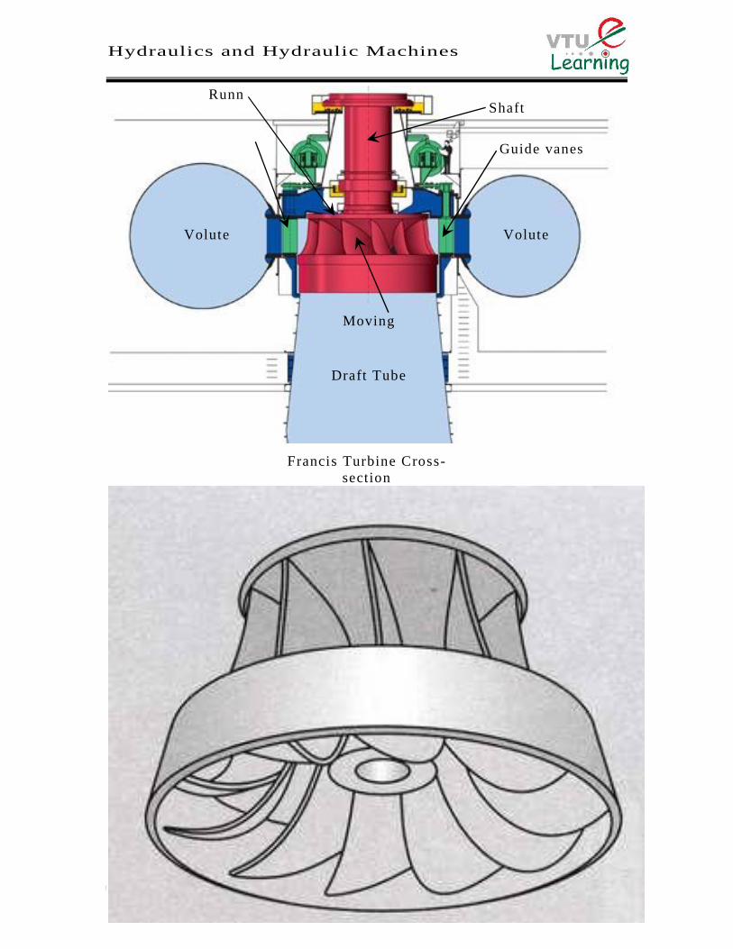
Francis Turbine Cross-section
Guide vanes
VoluteCasing
VoluteCasing
Guide vanes
Movingvanes
Draft Tube
ShaftRunn
er
Hydraulics and Hydraulic Machines
Dr. M.N. Shesha Prakash, Professor, J .N.N. College of Engineering, Shimoga 7
Guide vaneassembly

Hydraulics and Hydraulic Machines
Dr. M.N. Shesha Prakash, Professor, J .N.N. College of Engineering, Shimoga 8

Hydraulics and Hydraulic Machines
Dr. M.N. Shesha Prakash, Professor, J .N.N. College of Engineering, Shimoga 9
Derivation of the efficiency of a reaction turbine
Let
R1 = Radius of wheel at inlet of the vane
R2 = Radius of wheel at outlet of the vane
= Angular speed of the wheel
Tangential speed of the vane at inlet = u1 = R1
R1
R2
O
V2Vr2
u2
V f 2
Vw2F
GH
E
V1 Vr1
u1
V f 1
Vw1
B
D
CA
Wheel
Tangent
Tangent

Hydraulics and Hydraulic Machines
Dr. M.N. Shesha Prakash, Professor, J .N.N. College of Engineering, Shimoga 10
Tangential speed of the vane at outlet = u2 = R2
The velocity triangles at inlet and outlet are drawn as shown in Fig.
and are the angles between the absolute velocities of jet and vane at
inlet and outlet respectively
and are vane angles at inlet and outlet respectively
The mass of water striking a series of vanes per second = a V1
where a is the area of jet or flow and V1 is the velocity of flow at inlet .
The momentum of water striking a series of vanes per second at inlet is
given by the product of mass of water striking per second and the
component of velocity of flow at inlet
= a V1 x Vw1 (Vw1 is the velocity component of flow at inlet along
tangential direction)
Similarly momentum of water striking a series of vanes per second at
outlet is given by
= a V1 x (Vw2 ) (Vw2 is the velocity component of flow at outlet along
tangential direction and because the velocity
component is acting in the opposite direction)
Now angular momentum per second at inlet is given by the product of
momentum of water at inlet and its radial distance = a V1 x Vw1 x R1
And angular momentum per second at inlet is given by = a V1 x Vw2 x
R2
Torque exerted by water on the wheel is given by impulse momentum
theorem as the rate of change of angular momentum
T = a V1 x Vw1 x R1 a V1 x Vw2 x R2
T = a V1 (Vw1 R1+ Vw2 R2)
Workdone per second on the wheel = Torque x Angular veloci ty = T x
WD/s = a V1 (Vw1 R1+ Vw 2 R2) x
= a V1 (Vw1 R1 x + Vw2 R2 x )
As u1 = R1 and u2 = R2 , we can simplify the above equation as
WD/s = a V1 (Vw1 u1+ Vw 2 u2)
Hydraulics and Hydraulic Machines
Dr. M.N. Shesha Prakash, Professor, J .N.N. College of Engineering, Shimoga 11
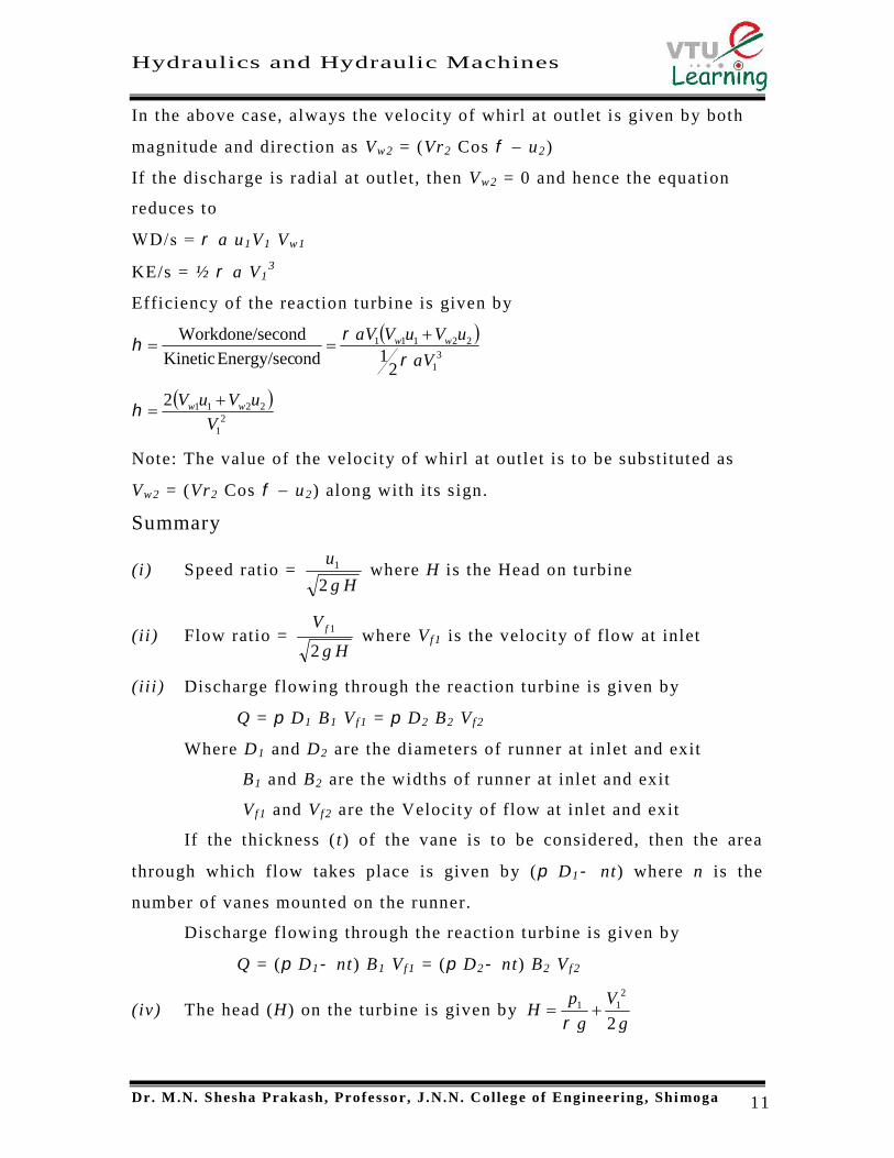
In the above case, always the velocity of whirl at outlet is given by both
magnitude and direction as Vw2 = (Vr2 Cos u2)
If the discharge is radial at outlet, then Vw2 = 0 and hence the equation
reduces to
WD/s = a u1V1 Vw1
KE/s = ½ a V13
Efficiency of the reaction turbine is given by
3
1
22111
21ondEnergy/secKinetic
econdWorkdone/s
Va
uVuVVa ww
2
1
22112V
uVuV ww
Note: The value of the velocity of whirl at outlet is to be substituted as
Vw2 = (Vr2 Cos u2) along with i ts sign.
Summary
(i) Speed ratio =Hg
u
21 where H is the Head on turbine
(ii) Flow ratio =Hg
V f
2
1 where V f 1 is the velocity of flow at inlet
(iii) Discharge flowing through the reaction turbine is given by
Q = D1 B1 V f 1 = D2 B2 V f 2
Where D1 and D2 are the diameters of runner at inlet and exit
B1 and B2 are the widths of runner at inlet and exit
V f 1 and V f 2 are the Velocity of flow at inlet and exit
If the thickness ( t) of the vane is to be considered, then the area
through which flow takes place is given by ( D1 nt) where n is the
number of vanes mounted on the runner.
Discharge flowing through the reaction turbine is given by
Q = ( D1 nt) B1 V f 1 = ( D2 nt) B2 V f 2
(iv) The head (H) on the turbine is given byg
V
g
pH
2
211

Hydraulics and Hydraulic Machines
Dr. M.N. Shesha Prakash, Professor, J .N.N. College of Engineering, Shimoga 12
Where p1 is the pressure at inlet.
(v) Work done per second on the runner = a V1 (Vw1u1 Vw2u2)
= Q (Vw1u1 Vw2u2)
(vi)60
11
NDu
(vi i)60
22
NDu
(viii) Work done per unit weight =secondperstriking waterofWeight
secondperdoneWork
= 2211
2211 1uVuV
ggQ
uVuVQww
ww
If the discharge at the exit is radial, then Vw2 = 0 and hence
Work done per unit weight = 11
1uV
g w
(ix) Hydraulic efficiency = 2211
2211 1
..
..uVuV
HgHQg
uVuVQ
PW
PRww
ww
If the discharge at the exit is radial, then Vw2 = 0 and hence
Hydraulic efficiency = 11
1uV
Hg w
Hydraulics and Hydraulic Machines
Dr. M.N. Shesha Prakash, Professor, J .N.N. College of Engineering, Shimoga 13
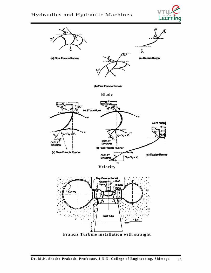
VelocityTriangles
BladeConfiguration
Francis Turbine installation with straightconical draft tube

Hydraulics and Hydraulic Machines
Dr. M.N. Shesha Prakash, Professor, J .N.N. College of Engineering, Shimoga 14
WORKING OF A KAPLAN TURBINE
The reaction turbine developed by Victor Kaplan (1815-1892) is an
improved version of the older propeller turbine. It is particularly suitable
for generating hydropower in locations where large quantities of water are
available under a relatively low head. Consequently the specific speed of
these turbines is high, viz., 300 to 1000. As in the case of a Francis
turbine, the Kaplan turbine is provided with a spiral casing, guide vane
assembly and a draft tube. The blades of a Kaplan turbine, three to eight
in number are pivoted around the central hub or boss, thus permitting
adjustment of their orientation for changes in load and head. This
arrangement is generally carried out by the governor which also moves the
guide vane suitably. For this reason, while a fixed blade propeller turbine
gives the best performance under the design load condit ions, a Kaplan
turbine gives a consistently high efficiency over a larger range of heads,
discharges and loads. The facility for adjustment of blade angles ensures
shock-less flow even under non-design conditions of operation.
Water entering radially from the spiral casing is imparted a substantial
whirl component by the wicket gates. Subsequently, the curvature of the
housing makes the flow become axial to some extent and finally then
relative flow as it enters the runner, is tangential to the leading edge of
Kaplan Turbine installation with an ElbowType Draft tube
Hydraulics and Hydraulic Machines
Dr. M.N. Shesha Prakash, Professor, J .N.N. College of Engineering, Shimoga 15
the blade as shown in Fig 1(c), Energy transfer from fluid to runner
depends essentially on the extent to which the blade is capable of
extinguishing the whirl component of fluid. In most Kaplan runners as in
Francis runners, water leaves the wheel axially with almost zero whirl or
tangential component. The velocity triangles shown in Fig 1(c) are at the
inlet and outlet tips of the runner vane at mid radius, i .e. , midway
between boss periphery and runner periphery.
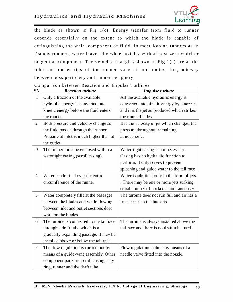
Comparison between Reaction and Impulse TurbinesSN Reaction turbine Impulse turbine1 Only a fraction of the available
hydraulic energy is converted into
kinetic energy before the fluid enters
the runner.
All the available hydraulic energy is
converted into kinetic energy by a nozzle
and it is the jet so produced which strikes
the runner blades.
2. Both pressure and velocity change as
the fluid passes through the runner.
Pressure at inlet is much higher than at
the outlet.
It is the velocity of jet which changes, the
pressure throughout remaining
atmospheric.
3 The runner must be enclosed within a
watertight casing (scroll casing).
Water-tight casing is not necessary.
Casing has no hydraulic function to
perform. It only serves to prevent
splashing and guide water to the tail race
4. Water is admitted over the entire
circumference of the runner
Water is admitted only in the form of jets.
. There may be one or more jets striking
equal number of buckets simultaneously.
5. Water completely fills at the passages
between the blades and while flowing
between inlet and outlet sections does
work on the blades
The turbine does not run full and air has a
free access to the buckets
6. The turbine is connected to the tail race
through a draft tube which is a
gradually expanding passage. It may be
installed above or below the tail race
The turbine is always installed above the
tail race and there is no draft tube used
7. The flow regulation is carried out by
means of a guide-vane assembly. Other
component parts are scroll casing, stay
ring, runner and the draft tube
Flow regulation is done by means of a
needle valve fitted into the nozzle.

Hydraulics and Hydraulic Machines
Dr. M.N. Shesha Prakash, Professor, J .N.N. College of Engineering, Shimoga 16
KAPLAN TURBINE - SUMMARY1. Peripheral velocities at inlet and outlet are same and given by
where Do is the outer diameter of the runner2. Flow velocities at inlet and outlet are same. i.e. V f 1 = V f 2
3. Area of flow at inlet is same as area of flow at outlet
where Db is the diameter of the boss.
6021
NDuu o
22
4 bo DDQ
Related Documents