© COPYRIGHT 2004, MULTIQUIP INC. OPERATION AND PARTS MANUAL EC-42S ESSICK SERIES CONCRETE MIXER Revision #8 (12/16/05) FINAL REVISION MULTIQUIP INC. PARTS DEPARTMENT: 18910 WILMINGTON AVE. 800-427-1244 CARSON, CALIFORNIA 90746 FAX: 800-672-7877 310-537-3700 SERVICE DEPARTMENT/TECHNICAL ASSISTANCE: 800-421-1244 800-478-1244 FAX: 310-537-3927 FAX: 310-631-5032 E-mail:[email protected] • www:multiquip.com Atlanta • Boise • Dallas • Houston • Newark Montreal, Canada • Manchester, UK Rio De Janiero, Brazil • Guadalajara, Mexico

Welcome message from author
This document is posted to help you gain knowledge. Please leave a comment to let me know what you think about it! Share it to your friends and learn new things together.
Transcript

© C
OP
YR
IGH
T 2
004,
MU
LTIQ
UIP
IN
C.
OPERATION AND PARTS MANUAL
EC-42SESSICK SERIES
CONCRETE MIXER
Revision #8 (12/16/05)
FINAL REVISION
MULTIQUIP INC..... PARTS DEPARTMENT:18910 WILMINGTON AVE. 800-427-1244CARSON, CALIFORNIA 90746 FAX: 800-672-7877310-537-3700 SERVICE DEPARTMENT/TECHNICAL ASSISTANCE:800-421-1244 800-478-1244FAX: 310-537-3927 FAX: 310-631-5032E-mail:[email protected] • www:multiquip.comAtlanta • Boise • Dallas • Houston • NewarkMontreal, Canada • Manchester, UKRio De Janiero, Brazil • Guadalajara, Mexico


EC-42S CONCRETE MIXER — PARTS & OPERATION MANUAL — REV. #8 (12/16/05) — PAGE 3
HERE'S HOW TO GET HELPPLEASE HAVE THE MODEL AND SERIAL
NUMBER ON-HAND WHEN CALLINGMULTIQUIP’S MAIN PHONE NUMBERS800-421-1244 FAX: 310-537-3927310-537-3700PARTS DEPARTMENT800-427-1244 FAX: 800-672-7877310-537-3700 FAX: 310-637-3284MAYCO PARTS800-306-2926 FAX: 800-672-7877310-537-3700 FAX: 310-637-3284SERVICE DEPARTMENT800-478-1244 FAX: 310-537-4259310-537-3700MQ POWER SERVICE DEPARTMENT800-835-2551 FAX: 310-638-8046310-537-3700TECHNICAL ASSISTANCE800-478-1244 FAX: 310-631-5032WARRANTY DEPARTMENT800-421-1244, EXT. 279 FAX: 310-537-1173310-537-3700, EXT. 279

PAGE 4 — EC-42S CONCRETE MIXERS — PARTS & OPERATION MANUAL — REV. #8 (12/16/05)
EC-42S CONCRETE MIXER — TABLE OF CONTENTS
Componet DrawingsNameplate and Decals ....................................... 34-35Mixer Assembly (Steel Drum) ............................ 36-37Mixer Assembly (Plastic Drum) .......................... 38-39Main Frame Assembly ....................................... 40-41Axle Assembly .................................................... 42-43Cabinet Assembly .............................................. 44-45Gas Engine Mounting Plate Asasembly ............ 46-47Electric Motor Mounting Plate Asasembly ........ 46-47
Specification and part numberare subject to change withoutnotice.
NOTE
MQ ESSICK EC-42S ConcreteMixerHere's How To Get Help ............................................ 3Table Of Contents ..................................................... 4Parts Ordering Procedures ....................................... 5Specifications ............................................................ 6Dimensions (Mixer) ................................................... 7Safety Message Alert Symbols ................................. 8Rules For Safe Operation .................................... 9-10Operation and Safety Decals .................................. 11General Information ................................................ 12Mixer Basic Components ........................................ 13Basic Engine Components ...................................... 14Handwheel Assembly .............................................. 15Towing Guidelines ................................................... 16Safety Chain Connection ........................................ 17Electric Motor ..................................................... 18-19Pre-Inspection (Gasoline Engine) ........................... 20Initial Start-up (Gasoline Engine)............................ 21Initial Start-up (Electric Motor) ................................ 22Operation ................................................................ 23Maintenance (Engine) ........................................ 24-25Maintenance (Mixer) .......................................... 26-28Troubleshooting (Engine) ........................................ 30Troubleshooting (Engine/Mixer) .............................. 31Explanation Of Code In Remarks Column .............. 32Suggested Spare Parts ........................................... 33
HONDA GX120K1QX2 ENGINEAir Cleaner Assy. ................................................ 48-49Camshaft Assy. .................................................. 50-51Carburetor Assy. ................................................ 52-53Control Assy. ...................................................... 54-55Crankcase Cover Assy. ...................................... 56-57Crankshaft Assy. ................................................ 58-59Cylinder Barrel Assy. .......................................... 60-61Cylinder Head Assy. ........................................... 62-63Fan Cover Assy. ................................................. 64-65Flywheel Assy..................................................... 66-67Fuel Tank Asssembly ......................................... 68-69Ignition Coil Asssembly ...................................... 70-71Muffler Asssembly .............................................. 72-73Piston Rings Asssembly ..................................... 74-75Recoil Starter Asssembly ................................... 76-77Gasket Kit Assembly .......................................... 78-79Labels Asssembly .............................................. 80-81
Terms and Conditions of Sale - Parts ................... 82

EC-42S CONCRETE MIXER — PARTS & OPERATION MANUAL — REV. #8 (12/16/05) — PAGE 5
When ordering parts,please supply the following information:
❒❒❒❒❒ Dealer account number❒❒❒❒❒ Dealer name and address❒❒❒❒❒ Shipping address (if different than billing address)❒❒❒❒❒ Return fax number❒❒❒❒❒ Applicable model number❒❒❒❒❒ Quantity, part number and description of each part❒❒❒❒❒ Specify preferred method of shipment:
✓ FedEx or UPS Ground✓ FedEx or UPS Second Day or Third Day✓ FedEx or UPS Next Day✓ Federal Express Priority One✓ DHL✓ Truck
Here’s how to get help...Please have the model and serial number onhand when calling.
Parts Department800-427-1244 Fax: 800-672-7877310-537-3700 Fax: 310-637-3284
Service Department800-478-1244 Fax: 310-537-4259310-537-3700
Technical Assistance800-478-1244 Fax: 310-631-5032
Warranty Department800-421-1244, Ext. 279 Fax: 310-537-1173310-537-3700, Ext. 279
Sales Department310-661-4242 Fax: 310-604-9237877-289-7869 (877-BUY-STOW)
Note: Unless otherwise indicated by customer, allorders are treated as “Standard Orders”, and willship within 24 hours. We will make every effort toship “Air Shipments” the same day that the order isreceived, if prior to 2PM west coast time. “StockOrders” must be so noted on fax or web forms.
Extra Discounts!All parts orders which include complete part numbersand are received by our automated web parts ordersystem, or by fax qualify for the following extradiscounts:
Ordered Standard Stock ordersvia orders ($750 list and above)
Fax 3% 10%
Web 5% 10%
Special freight allowanceswhen you order 10 or moreline items via Web or Fax!**FedEx Ground Service at no charge for freightNo other allowances on freight shipped by any othercarrier.
Place Your Parts Order Via Web or FaxFor Even More Savings!
NOTE: DISCOUNTS ARE SUBJECT TO CHANGE
Direct TOLL-FREE accessto our Parts Department:
Toll-free nationwide — 800-427-1244
STOW CONSTRUCTION EQUIPMENTSTOW CONSTRUCTION EQUIPMENTSTOW CONSTRUCTION EQUIPMENTSTOW CONSTRUCTION EQUIPMENTSTOW CONSTRUCTION EQUIPMENTA DIVISION OF STOW INC.POST OFFICE BOX 6254CARSON, CA 90749310-537-3700 • 888-252-STOW [888-252-7869]FAX: 310-537-1986 • FAX: 800-556-1986E-MAIL: [email protected] • WWW: stowmfg.com
EC-42S CONCRETE MIXER — PARTS ORDERING PROCEDURES

PAGE 6 — EC-42S CONCRETE MIXERS — PARTS & OPERATION MANUAL — REV. #8 (12/16/05)
EC-42S CONCRETE MIXER — SPECIFICATIONS
)rotoMcirtcelE/enignE(snoitacificepS.1elbaT
cirtcelE/enignErotoM
ledoM 2XQ1K021XGADNOH 6955-423F43rodlaB
epyTelgniS,ekorts4delooc-riA
tfahSlatnoziroH,VHO,rednilyCenignEenilosaG
511esahp-elgniS,PH2/1rotoMcirtcelE,CAV
ekortSXeroB.ni7.1X.ni7.2
)mm24xmm06(A/N
tnemecalpsiD )cc911(.ni.uc3.7 A/N
tuptuOxaM mpr006,3/.P.H9.3 .M.P.R5271/PH2/1
yticapaCknaTleuF )sretiL06.0(snollaG.S.U36.0 A/N
leuF enilosaGelibomotuAdedaelnU A/N
yticapaCliOebuL )retil6.0(.tq36.0 A/N
lortnoCdeepSdohteM
epyTthgiew-ylFlagufirtneC A/N
dohteMgnitratS tratSlioceR cirtcelE
egatloVtupnI A/N esahPelgniSCAV511
noisnemiD)HxWxL(
.ni5.21X4.31x7.11)mm813X143X792(
.ni26.8X65.7x78.31)mm912X291X253(
thgieWteNyrD ).gK0.31(sbl7.82 ).gk4.5(sbl21.xorppA
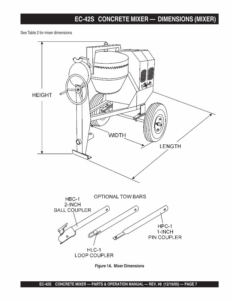
snoitacificepSrexiMS24-CE.2elbaTthgieH )mm525,1(.ni06
htdiW )mm692,1(.ni15
htgneL )mm776,1(.ni66
yticapaCmurDmumixaM )sretil081(.tf.uc53.6
yticapaCgnixiMmumixaM )sretil311(.tf.uc0.4
yticapaCgaB )gab2/1ot3/1(
rotoMcirtcelE/enignEhtiW-thgieW ).gK422(.sbl594
EC-42S CONCRETE MIXER — PARTS & OPERATION MANUAL — REV. #8 (12/16/05) — PAGE 7
EC-42S CONCRETE MIXER — DIMENSIONS (MIXER)
See Table 2 for mixer dimensions
Figure 1A. Mixer Dimensions

PAGE 8 — EC-42S CONCRETE MIXERS — PARTS & OPERATION MANUAL — REV. #8 (12/16/05)
Accidental Starting
ALWAYS place the circuit breaker or powerON/OFF switch in the OFF position when thepump is not in use.
Respiratory Hazard
ALWAYS wear approved respiratoryprotection.
Equipment Damage Messages
Other important messages are provided throughout this manualto help prevent damage to your mixer, other property, or thesurrounding environment.
ALWAYS wear approved eye and hearingprotection.
Sight and Hearing hazard
EC-42S CONCRETE MIXER — SAFETY MESSAGE ALERT SYMBOLS
Safety precautions should be followed at all times whenoperating this equipment. Failure to read and understand theSafety Messages and Operating Instructions could result ininjury to yourself and others.
FOR YOUR SAFETY AND THE SAFETY OF OTHERS!
This Owner's Manual has beendeveloped to provide completeinstructions for the safe and efficientoperation of the MQ Essick ModelEC-42S (Steel) Concrete Mixer.Before using this mixer,ensure that the operatingindividual has read andunderstands all instructions inthis manual.
SAFETY MESSAGE ALERT SYMBOLS
The three (3) Safety Messages shown below will inform youabout potential hazards that could injure you or others. TheSafety Messages specifically address the level of exposure tothe operator, and are preceded by one of three words: DANGER,WARNING, or CAUTION.
DANGER: You WILL be KILLED orSERIOUSLY injured if you do not followdirections.
WARNING: You CAN be KILLED orSERIOUSLY injured if you do not followdirections.
CAUTION: You CAN be injured if youdo not follow directions.
HAZARD SYMBOLS
Potential hazards associated with the MQ Essick EC-42Sconcrete mixer operation will be referenced with Hazard Symbolswhich appear throughout this manual, and will be referenced inconjunction with Safety Message Alert Symbols.
Rotating Parts
NEVER operate equipment with covers, orguards removed. Keep fingers, hands, hair andclothing away from all moving parts to preventinjury.NOTE
This mixer, other property, or thesurrounding environment couldbe damaged if you do not followinstructions.
NOTE

EC-42S CONCRETE MIXER — PARTS & OPERATION MANUAL — REV. #8 (12/16/05) — PAGE 9
EC-42S CONCRETE MIXER — RULES FOR SAFE OPERATION
■ ALWAYS refuel in a well-ventilated area, away from sparksand open flames.
■ ALWAYS use extreme caution when working with flammableliquids. When refueling, stop the engine and allow it to cool.DO NOT smoke around or near the machine. Fire or explosioncould result from fuel vapors, or if fuel is spilled on a hotengine.
■ NEVER operate the mixer in an explosiveatmosphere or near combustiblematerials. An explosion or fire could resultcausing severe bodily harm or evendeath.
■ Topping-off to filler port is dangerous, as it tends to spill fuel.
■ Refer to the Engine Owner's Manual for engine technicalquestions or information.
■ NEVER use accessories or attachments, which are notrecommended by Multiquip for this equipment. Damage tothe equipment and/or injury to user may result.
■ Manufacturer does not assume responsibility for any accidentdue to equipment modifications.
■ NEVER touch the hot exhaust manifold,muffler or cylinder. Allow these parts tocool before servicing engine or mixer.
■ The engine of this mixer requires an adequate free flow ofcooling air. NEVER! operate the mixer in any enclosed or
narrow area where freeflow of the air is restricted. Ifthe air flow is restricted itwill cause serious damageto the mixer or engine andmay cause injury to peopleand property. Rememberthe mixer's engine(gasoline models only)gives off DEADLY gases.
■ High Temperatures – Allow the engine to cool before addingfuel or performing service and maintenance functions. Contactwith hot components can cause serious burns.
DANGER:Failure to follow instructions in this manual maylead to serious injury or even death! Thisequipment is to be operated by trained andqualified personnel only! This equipment is forindustrial use only.
The following safety guidelines should always be used whenoperating the MQ Essick EC-42S Concrete Mixer:
GENERAL SAFETY
■ DO NOT operate or service this equipment beforereading this entire manual.
■ This equipment should not be operated bypersons under 18 years of age.
■ NEVER operate this equipment without properprotective clothing, shatterproof glasses, steel-toed boots and other protective devices requiredby the job.
■ NEVER operate this equipment when not feelingwell due to fatigue, illness or taking medicine.
■ NEVER operate this equipment under theinfluence or drugs or alcohol.
■ Whenever necessary, replace nameplate, operation andsafety decals when they become difficult read.
■ ALWAYS check the machine for loosened threads or boltsbefore starting.
■ ALWAYS wear proper respiratory (mask) hearing and eyeprotection equipment when operating the mixer.
■ NEVER! place hands inside the drum while the drum isrotating.

PAGE 10 — EC-42S CONCRETE MIXERS — PARTS & OPERATION MANUAL — REV. #8 (12/16/05)
■ In emergencies always know the location of thenearest phone or keep a phone on the job site.Also know the phone numbers of the nearestambulance, doctor and fire department. Thisinformation will be invaluable in the case of anemergency.
■ NEVER disconnect any "emergency or safety devices".These devices are intended for operator safety. Disconnectionof these devices can cause severe injury, bodily harm or evendeath! Disconnection of any of these devices will void allwarranties.
■ If mixer is equipped with an electric motor, operate electricmotor only at the specified voltage indicated on the nameplate.
■ Make sure the OFF/ON power switch on the electric motor isalways in the OFF position before inserting the mixer's powerplug into an AC receptacle (electric model only).
Maintenance Safety■ NEVER lubricate components or attempt service on a running
machine.
■ ALWAYS allow the machine a proper amount of time to coolbefore servicing.
■ Keep the machinery in proper running condition.
■ Fix damage to the machine immediately and always replacebroken parts, or missing decals.
■ Dispose of hazardous waste properly. Examples of potentiallyhazardous waste are used motor oil, fuel and fuel filters.
■ DO NOT use food or plastic containers to dispose ofhazardous waste.
■ DO NOT pour waste, oil or fuel directly onto the ground,down a drain or into any water source.
Emergencies
■ ALWAYS know the location of the nearest fire extinguisherand first aid kit.
EC-42S CONCRETE MIXER — RULES FOR SAFE OPERATION■ NEVER run engine without air cleaner. Severe engine damage
may occur.
■ ALWAYS read, understand, and follow procedures inOperator’s Manual before attempting to operate equipment.
■ ALWAYS be sure the operator is familiar with proper safetyprecautions and operations techniques before using roller.
■ ALWAYS store equipment properly when it is not being used.Equipment should be stored in a clean, dry location out of thereach of children.
■ NEVER leave the mixer unattended, turn off engine or electricmotor when unattended.
■ CAUTION must always be observed while servicing this mixer.Rotating parts can cause injury if contacted.
■ Unauthorized equipment modifications will void allwarranties.
■ Ensure that any extension cable is protected against damageand not liable to be tripped over or trapped underneath themixer.
■ DO NOT allow extension cord to come into contact with wateror fluids.
■ DO NOT spray water onto electric motor.
■ This mixer is intended for the production of concrete. Mixermust be used only for its intended purpose.
■ This mixer is not suitable for the mixing of flammable orexplosive substances.
■ NEVER operate the mixer in an explosive atmosphere.
■ Before starting the mixer, check that all guards are in positionand correctly fitted.
■ Keep area around the mixer clear of obstructions whichcould cause persons to fall onto moving parts.
■ ALWAYS ensure mixer is on level ground before mixing.
■ Become familiar with the controls of the mixer beforeoperating.
■ ALWAYS replace any worn or damaged warning decals.
■ Ensure the drum is rotating while filling and emptying thedrum.
■ ALWAYS disconnect AC power plug from power sourcebefore moving mixer (electric model only).
■ High Temperatures – Always stop engine and allow theengine to cool before adding fuel, oil or performing serviceand maintenance functions. Contact with hot componentscan cause serious burns.

EC-42S CONCRETE MIXER — PARTS & OPERATION MANUAL — REV. #8 (12/16/05) — PAGE 11
EC-42S CONCRETE MIXER — OPERATION AND SAFETY DECALS
Machine Safety Decals
The MQ Essick EC-42S mixer is equipped with a number of safety decals (Figure 1A). These decals are provided for operator safetyand maintenance information. The illustration below and on the next page shows these decals as they appear on the machine.Should any of these decals become unreadable, replacements can be obtained from your dealer.
Figure 1A. EC-42S Mixer Decals

PAGE 12 — EC-42S CONCRETE MIXERS — PARTS & OPERATION MANUAL — REV. #8 (12/16/05)
EC-42S CONCRETE MIXER — GENERAL INFORMATIONApplication
This mixer is only intended for the production of concrete.The mixer must be used for its intended purpose and is notsuitable for the mixing of flammable or explosivesubstances. The mixer must not be used in an explosiveatmosphere. Use Table 4 (Mixing Hints) as a guide whenmixing concrete for various applications.
Power Plants
The MQ Essick mixer can be powered by either a HondaGX120K1QX2 air-cooled, 4-stroke gasoline engine or a 1/2HP electric motor. Refer to Table 1 to for specific engine orelectric motor data information.
Electrical
If mixer is equipped with an electric motor, make sure thatthe power being supplied to the motor corresponds to thevoltage rating label on the motor. Supplying the wrong voltageto the electric motor will cause severe electrical damage tothe motor.
Always make sure the OFF/ON switch on the electric motoris in the OFF position before applying power.
It is strongly recommended when inserting the mixer'spower cord into a receptacle, that a G.F.C.I. (Ground FaultCurrent Interrupter) receptacle be used (115 VACapplications).
Extension Cables
The extension cable should be a 3-wire configuration thatincludes a ground wire that conforms to UL code. The wirecross section must be a minimum of 2.5 mm2 . Choose anextension cord of adequate current carrying as Referencedin Table 6. Remember distance affects the wire size of theextension cable.
Ensure that the extension cable is carefully laid out avoid-ing wet areas, sharp edges and locations where vehiclesmight run over it. Avoid allowing the extension cable to betrapped underneath the mixer.
Unroll the extension cable fully or it will overheat and couldcatch fire. Make sure that all extension cable connectionsare dry and safe. Replace any defective or badly worn ex-tension cable immediately.
Hardware
Check all hardware on the mixer before starting. Periodicallyinspect all hardware. Loose hardware can contribute to earlycomponent failure and poor performance. Use Table 3 as generalguideline when the torqueing of mixer hardware is required.Remember to keep all mixer hardware components tight.
Engine Maintenance
For basic engine maintenance, refer to the engine maintenancesection in this manual. For a more detailed engine maintenance,refer to the Honda Engine Owner's manual furnished with theengine.
euqroTerawdraH.3elbaTnoitadnemmoceR s
erawdraHretemaiD
)sbl-tf(euqroT
81xhcni-61/5 41
61xhcni-8/3 42
42xhcni-8/3 73
31xhcni-2/1 93
31xhcni-2/1)8edarG(
09
STNIHGNIXIM.4elbaT
SNOITACILPPAXIM
SOITAR
SEITITNAUQHCTABHCTAB.XORPPA
TUPTUO.sbl211TNEMEC).sgK05(
gaB
DNAS ENOTS
.TF.UC RTL .TF.UC RTL .TF.UC RTL
yranidrOtsoM 4:2:1 GAB2/1 4/1-1 53 2/1-2 17 3 58
snoitadnuoF 6:3:1 GAB3/1 4/1-1 53 2/1-2 17 4/3-2 87
ssaMhguoRetercnoC
8:4:1 GAB4/1 4/1-1 53 2/1-2 17 4/3-2 87
,sroolFthgitretaW.ctE,stiP,sknaT
3:2/1-1:1 GAB3/2 4/1-1 53 3 17 3 58

EC-42S CONCRETE MIXER — PARTS & OPERATION MANUAL — REV. #8 (12/16/05) — PAGE 13
EC-42S CONCRETE MIXER — MIXER BASIC COMPONENTS
Figure 2. Mixer Major Components
1. Steel Mixing Drum — The MQ Essick EC-42S uses a 4cu. ft steel mixing drum. This drum is to be used for mixingof concrete. Always clean the drum after each use. DONOT use this mixing drum for the mixing of volatile liquids.
2. Dump Latch — To rotate the mixing drum, this latch mustbe in the up position. To lock the drum, place the latch in thedown position.
3. Dump Gear Guard — NEVER operate the mixer with thisguard removed. Its purpose is to prevent dirt and debrisfrom entering the dump gear. In addition operator clothingcould become entangled in the dump gear, causing severeinjury and bodily harm.
4. Handwheel — Turn this wheel clockwise or counter-clockwise to rotate the mixing drum. Remember the dumplatch must be in the up position in order for the mixingdrum to be rotated.
5. Zerk Fittings — There is, at the bottom and engine sideof the yoke, and center of the handwheel grease zerkfittings. Lubricate these fittings as referenced in themaintenance section of this manual.
6. Safety Chain — This mixer uses a 3/16-inch thick, 72-inches long zinc-plated saftey chain. ALWAYS connect thesafety chain when towing.
7. Tow Bar — This mixer uses various towing bars, pleasereference the frame assembly drawing and parts list in thismanual to determine which tow bar meets yourrequirements.
8. Leaf Suspension — This mixer uses a leaf typesuspension. Check the mounting hardware for bolt holeelongation and tightness. See maintenance section of thismanual for recommended maintenance.
9. Chock Blocks — Place these blocks (not included aspart of the mixer package) under each mixer wheel toprevent rolling, when mixer is not connect to the towingvehicle.
10. Tires Ply — The tire ply (layers) number is rated in letters;This mixer uses 13-inch 2-ply tires. Replace with onlyrecommended type tires.
11. ON/OFF Switch (gasoline only) — This switch is providedon mixerwith gasoline engines only and is located on theside of the mixer frame. When activated it will shut downthe engine. Pull out when starting the engine.
12. Cabinet/Latch — Encloses engine and electric motor.NEVER run mixer with cabinet removed. Use latches tosecure engine compartment cabinet.
13. Mixing Blades (Steel) — Used for the mixing of concrete.When blades show signs of wear, entire steel mixing drumassembly must be replaced. See steel mixing drumassembly in the parts section of this manual.

PAGE 14 — EC-42S CONCRETE MIXERS — PARTS & OPERATION MANUAL — REV. #8 (12/16/05)
EC-42S CONCRETE MIXER — BASIC ENGINE COMPONENTS
Figure 3. Engine Controls and Components
INITIAL SERVICING
The engine (Figure 3) must be checked for proper lubrication andfilled with fuel prior to operation. Refer to the manufacturers Enginemanual for instructions & details of operation and servicing.
1. Fuel Filler Cap – Remove this cap to add unleadedgasoline to the fuel tank. Make sure cap is tightenedsecurely. DO NOT over fill.
Adding fuel to the tank should be accomplished onlywhen the engine is stopped and has had anopportunity to cool down. In the event of a fuel spill,
DO NOT attempt to start the engine until the fuel residue has beencompletely wiped up, and the area surrounding the engine is dry.
2. Throttle Lever – Used to adjust engine RPM speed (leveradvanced forward SLOW, lever back toward operatorFAST).
3. Engine ON/OFF Switch – ON position permits enginestarting, OFF position stops engine operations.
4. Recoil Starter (pull rope) – Manual-starting method. Pullthe starter grip until resistance is felt, then pull briskly andsmoothly.
5. Fuel Valve Lever – OPEN to let fuel flow, CLOSE to stopthe flow of fuel.
6. Choke Lever – Used in the starting of a cold engine, or incold weather conditions. The choke enriches the fuelmixture.
7. Air Cleaner – Prevents dirt and other debris from enteringthe fuel system. Remove wing-nut on top of air filtercannister to gain access to filter element.
8. Spark Plug – Provides spark to the ignition system. Setspark plug gap to 0.6 - 0.7 mm (0.028 - 0.031 inch). Cleanspark plug once a week.
9. Muffler – Used to reduce noise and emissions.
Engine components can generate extreme heat.To prevent burns, DO NOT touch these areas
while the engine is running or immediately after operating. NEVERoperate the engine with the muffler removed.
10. Fuel Tank – Holds unleaded gasoline. For additionalinformation refer to engine owner's manual.
WARNINGWARNING
NOTEOperating the engine without an air filter,with a damaged air filter, or a filter in need ofreplacement will allow dirt to enter theengine, causing rapid engine wear.
WARNING
Honda GX Series Engine Shown

EC-42S CONCRETE MIXER — PARTS & OPERATION MANUAL — REV. #8 (12/16/05) — PAGE 15
EC-42S CONCRETE MIXER — HANDWHEEL ASSEMBLYAssembly
The MQ Essick EC-42S concrete mixer is shipped withthe handwheel detached. Attach the handwheel to the mixeras shown in Figure 4.
Figure 4. Handwheel Assembly

PAGE 16 — EC-42S CONCRETE MIXERS — PARTS & OPERATION MANUAL — REV. #8 (12/16/05)
EC-42S CONCRETE MIXER — TOWING GUIDELINES
To reduce the possibility of an accident while transportingthe mixer on public roads, always make sure that the mixertowing components and the towing vehicle are in goodoperating condition and both units are mechanically sound.
The following list of suggestions should be used when towingthe mixer:
CAUTION:CAUTION:CAUTION:CAUTION:CAUTION:Towing Safety Precautions
■ Check with your county or state safetytowing regulations department beforetowing your mixer.
■ Make sure that the hitch and coupling of the towing vehicleare rated equal to, or greater than the trailer "gross vehicleweight rating" (GVWR).
■ ALWAYS inspect the hitch and coupling for wear. NEVERtow the mixer with defective hitches, couplings, chains etc.
■ CHECK the tire air pressure on both the towing vehicle andthe trailer. Also check the tire tread wear on both vehicles.
■ ALWAYS make sure the mixer is equipped with a "SafetyChain".
■ ALWAYS attach trailer's safety chain to the frame of towingvehicle.
■ ALWAYS make sure that the towing vehicle's directional,backup, and brake lights are working properly.
■ Remember in most cases the maximum speed unlessotherwise posted for highway towing is 45 MPH, howeverbefore towing your mixer, check your local state, and countyvehicle towing requirements. Recommended off-road towingis not to exceed 10 MPH or less depending on type of terrain.
■ Place chocked blocks underneath wheels to prevent rolling,while parked, if disconnected from towing vehicle.
■ Inflate tires to correct pressure, inspect tires for cuts, andexcessive wear. See Table 16 (Tire Wear Troubleshooting).
■ When towing of the mixer is required, place the drum in theup position (mouth facing upwards).
■ ALWAYS make sure that the fuel valve lever is in the OFFposition (gasoline models only).
CAUTION:CAUTION:CAUTION:CAUTION:CAUTION:If the mixer tow bar is deformed or damagedreplace entire tow bar. NEVER tow the mixerwith a defective tow bar. There exist thepossibility of the trailer separating from thetowing vehicle.
Tow Bar to Vehicle Connection (Coupler Only)
1. Check the vehicle hitch ball, and mixer's coupler forsigns of wear or damage. Replace any parts that areworn or damaged before towing.
2. Use only a 2-inch ball diameter (towing vehicle), thiswill match the mixer's 2-inch coupler. Use of any otherball diameter will create an extremely dangerous conditionwhich can result in separation of the coupler and ball orball failure.
3. After tow bar has been connected to mixer (see nextpage), attach mixer's coupler to the hitch ball on thetowing vehicle securely and make sure the lock leveris in the down position (locked).
Mixer Tow Bar Vehicle Connection (Pentile and Loop)
1. Make sure the bumper on the towing vehicle is equippedto handle either a pentile or loop type tow barconfiguration.
2. After tow bar has been connected to mixer (see nextpage), secure either type of tow bar to the towing vehicle,following state and county towing regulations.
3. As a minimum, use a 1/2-inch bolt and nylock nut grade5 when securing either tow bar to the towing vehicle,
■ Check wheel mounting lug nuts with a torque wrench.Torque wheel lug nuts as described in the maintenancesection of this manual.
■ Check tightness of U-clamp nuts, torque suspensionhardware as referenced in the maintenance section of thismanual.
■ Avoid sudden stops and starts. This can cause skidding, orjackknifing. Smooth, gradual starts and stops will improvegas milage.
■ Avoid sharp turns to prevent rolling.

EC-42S CONCRETE MIXER — PARTS & OPERATION MANUAL — REV. #8 (12/16/05) — PAGE 17
EC-42S CONCRETE MIXER — SAFETY CHAIN CONNECTION
NEVER ! tow the mixer with the safety chainremoved. The safety chain is intended toprevent complete separation of the mixer fromthe towing vehicle in the event of a tow barfailure.
CAUTION:CAUTION:CAUTION:CAUTION:CAUTION:
Reference Figure 5 for the installation of the Saftey Chain.
Tow Bar to Mixer Connection
1. Insert the tow bar through the round opening at thebottom of the mixer stand.
Align the hole on the tow bar with the hole on the mixerframe, and insert 1/2-inch bolt through tow bar and frame.Secure tow bar to frame with 1/2-inch nylock nut. Tightento 40 ft.-lbs.
2. Route the safety chain through the holes just above thetow bar, located on each side of the mixer stand.
Loop the chain together and place under the tow bar.Secure the loop with the connector link.
3. Extend the safety chain along the length of the tow bar,looping it through the tow bar's connector link. Removeany excess chain slack.
4. Connect the free end of (connector link) the safety chainto the towing vehicle. Remember it is critical that thelength of the chain be properly adjusted, to preventthe draw bar and the front of the mixer stand fromdropping to the the ground (contact) in the event thedraw bar becomes disconnected from the towing vehicle.
Figure 5. Tow Bar and Safety Chain Installation
PAGE 18 — EC-42S CONCRETE MIXERS — PARTS & OPERATION MANUAL — REV. #8 (12/16/05)
EC-42S CONCRETE MIXER — ELECTRIC MOTOR
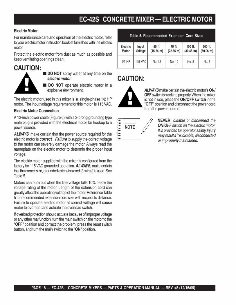
Electric Motor
For maintenance care and operation of the electric motor, referto your electric motor instruction booklet furnished with the electricmotor.
Protect the electric motor from dust as much as possible andkeep ventilating openings clean.
The electric motor used in this mixer is a single-phase 1/2 HPmotor. The input voltage requirement for this motor is 115 VAC.
Electric Motor Connection
A 12-inch power cable (Figure 6) with a 3-prong grounding typemale plug is provided with the electrical motor for hookup to apower source.
ALWAYS, make certain that the power source required for theelectric motor is correct . Failure to supply the correct voltageto the motor can severely damage the motor. Always read thenameplate on the electric motor to determin the proper inputvoltage.
The electric motor supplied with the mixer is configured from thefactory for 115 VAC grounded operation. ALWAYS, make certainthat the correct size, grounded extension cord (3-wires) is used. SeeTable 5.
Motors can burn out when the line voltage falls 10% below thevoltage rating of the motor. Length of the extension cord cangreatly affect the operating voltage of the motor. Reference Table5 for recommended extension cord size with recpect to distance.Failure to operate electric motor at correct voltage will causemotor to overheat and actuate the overload switch.
If overload protection should actuate because of improper voltageor any other malfunction, turn the main switch on the motor to the"OFF" position and correct the problem, press the reset switchbutton, and turn the main switch to the "ON" position.
CAUTION:■ DO NOT spray water at any time on the
electric motor.■ DO NOT operate electric motor in a
explosive environment.
NOTE
NEVER! disable or disconnect theON/OFF switch on the electric motor.It is provided for operator safety. Injurymay result if it is disable, disconnectedor improperly maintained.
seziSdroCnoisnetxEdednemmoceR.5elbaT
cirtcelErotoM
tupnIegatloV
.tf05)m42.51(
.tf57)m68.22(
.tf001)m84.03(
.tf002)m69.06(
PH2/1 CAV511 21.oN 01.oN 8.oN 6.oN
CAUTION:
ALWAYS make certain the electric motor's ON/OFF switch is working properly. When the mixeris not in use, place the ON/OFF switch in the"OFF" position and disconnect the power cordfrom the power source.

EC-42S CONCRETE MIXER — PARTS & OPERATION MANUAL — REV. #8 (12/16/05) — PAGE 19
Figure 6. Single Phase Electric Motor with 12 inch Pigtail Cable
EC-42S CONCRETE MIXER — ELECTRIC MOTOR

PAGE 20 — EC-42S CONCRETE MIXERS — PARTS & OPERATION MANUAL — REV. #8 (12/16/05)
EC-42S CONCRETE MIXER — PRE-INSPECTION (GAS ENGINE)
Figure 7. Engine Oil Dipstick (Removal)
3. Insert and remove the dipstick without screwing it into thefiller neck. Check the oil level shown on the dipstick.
4. If the engine oil level is low (Figure 8), fill to the edge ofthe oil filler hole with the recommended oil type (Table 6).See Table 2 for the oil capacity of your type engine.
Figure 8. Engine Oil Dipstick (Oil Level)
Fuel CheckIf your mixer has a gasoline engine, determine if the engine fuelis low. If fuel is low, remove the fuel filler cap and fill with unleadedgasoline. Motor fuels are highly flammable and can be dangerousif mishandled. DO NOT smoke while refueling. DO NOT attemptto refuel the trowel if the engine is hot! or running.
1. Remove the gasoline cap located on top of fuel tank.
2. Visually inspect to see if fuel level is low. If fuel is low, replenishwith unleaded fuel.
3. When refueling, be sure to use a strainer for filtration. DONOT top-off fuel. Wipe up any spilled fuel.
V-belt Check
A worn or damaged V-belt can adversely affect the performanceof the mixer. If a V-belt is defective or worn simply replace the V-belt as outlined in the maintenance section of this manual.
Blade Check
Check for worn blades. If using a steel tub and the blades areworn, replace the entire tub assembly. Remember the bladesare welded to tub.
If using a plastic tub, replace the blades using the part numbersreferenced in the parts section of this manual.
Start/Stop Switches
This mixer has been equipped with a start/stop switches for boththe gasoline and electric motor mixers. These switches should betested every time the engine or motor is started.
Grease Fittings (Zerk)
Check the zerk grease fittings (Figure 27) as shown in themaintenance section of this manual. These grease fittings lubricatethe handwheel and the yoke mechanism.
Explosive Fuel
Before Starting
1. Read safety instructions at the beginning of manual.
2. Clean the mixer, removing dirt and dust, particularly theengine cooling air inlet, carburetor and air cleaner.
3. Check the air filter for dirt and dust. If air filter is dirty, replaceair filter with a new one as required.
4. Check carburetor for external dirt and dust. Clean with drycompressed air.
5. Check fastening nuts and bolts for tightness.
Engine Oil Check
1. To check the engine oil level, place the mixer onsecure level ground with the engine stopped.
2. Remove the filler dipstick from the engine oil filler hole(Figure 7) and wipe it clean.
epyTliO.6elbaT
nosaeS erutarepmeT epyTliO
remmuS rehgiHroC°52 03-W01EAS
llaF/gnirpS C°01~C°52 02/03-W01EAS
retniW rewoLroC°0 01-W01EAS

EC-42S CONCRETE MIXER — PARTS & OPERATION MANUAL — REV. #8 (12/16/05) — PAGE 21
EC-42S CONCRETE MIXER — INITIAL START-UP (GAS ENGINE)Starting the Engine (Gasoline Only)
The following steps outline the procedure for starting the engine.Depending on the type of engine employed in the mixer thesteps may vary slightly. If your mixer has an electric motordisregard this section.
1. Move the fuel shut-off lever (Figure 9) to the ON position.
Figure 9. Fuel Shut-OFF Lever
2. To start a cold engine, move the choke lever (Figure 10) tothe CLOSED position.
Figure 10. Choke Lever3. Move the throttle lever (Figure 11) away from the slow
position, about 1/3 of the way toward the fast position.
Figure 11. Throttle Lever
4. Turn the engine switch (Figure 12) to the ON position.
Figure 12. Engine ON/OFF Switch
5. Located at the rear of the mixer frame is the main start/stop button (Figure 13). Pull this button outward to start theengine.
Figure 13. Engine Start/Stop Button
Figure 14. Starter Grip
6. Pull the starter grip (Figure 14) lightly until you feelresistance, then pull briskly. The drum should be rotating atthis time.

PAGE 22 — EC-42S CONCRETE MIXERS — PARTS & OPERATION MANUAL — REV. #8 (12/16/05)
CAUTION:CAUTION:CAUTION:CAUTION:CAUTION:DO NOT attempt to operate the mixer untilthe Safety, General Information andInspection sections have been read andunderstood.
Initial Start-up Instructions (Electric Motor)
Starting
1. Before starting, make sure mixer is positioned on a secureflat surface to prevent rolling.
2. Use an extension cord (see Table 5) of adequate currentcarrying capacity, insert the electric motor's power plug intoone end of the extension cord.
3. NEVER! use a worn or frayed extension cord.
4. NEVER! operate mixer with V-belt cover removed.
DANGERDANGERDANGERDANGERDANGER NEVER! touch the power cord (Figure 15)with wet hands or while standing in waterwhen it is connected to a power source. Thepossibly exists of electrical shock(electrocution) even death. NEVER! spraywater directly on the electric motor.
Figure 15. Extension Cord (Wet Hands)
WARNING:WARNING:WARNING:WARNING:WARNING:ALWAYS read the label on the electric motorbefore applying power. The label will indicatethe correct power requirements for the motor.Remember the use of an incorrect inputvoltage will severely damage the electricmotor.
To prevent personnel from tripping overthe extension cord, position theextension cord so that it lays flat and isnot curled underneath the mixer.
EC-42S CONCRETE MIXER — INITIAL START-UP (ELECT. MOTOR)
Starting the Electric Motor1. Set the electric motor's ON/OFF switch (Figure 17) to the
ON position.
NOTE
Figure 17. Electric Motor ON/OFF Switch (ON Position)
5. Plug the other end of the extension cord into a 120 VACG.F.C.I. protected receptacle. Remember the power require-ments for this electric motor is 120 VAC, 60 Hz. The use ofany other input voltage will severely damage the motor.
CAUTION:CAUTION:CAUTION:CAUTION:CAUTION:ALWAYS read the label on the electric motorbefore applying power. The label will indicatethe proper power requirements for the motor.Remember the use of any other input voltagewill severely damage the motor.
CAUTION:CAUTION:CAUTION:CAUTION:CAUTION:To prevent tripping (Figure 16) of both themixer and personnel, position the extensioncord so that it lays flat and is not curledunderneath the mixer.
Figure 16. Mixer (Tripping)

EC-42S CONCRETE MIXER — PARTS & OPERATION MANUAL — REV. #8 (12/16/05) — PAGE 23
2. As the drum rotates, use a shovel (Figure 19) to place thecement mix inside the drum, add water as required. Be carefulto only place the tip of the shovel inside the drum.
Figure 18. Mixing Drum Positioning
3. Placing the shovel all the way inside the drum (Figure 20) willcause the shovel to strike the blades. This condition will makethe shovel rotate, and could cause injury to personnel.NEVER place hands inside the mixing drum while it isrotating.
Operation
1. To position the tub, make sure the mixer is placed on firm levelground, then pull up on the dump latch (Figure 18) and turnthe hand wheel until the tub is at the desired position. Oncethe tub is at the desired position, pull down on the dump latchto lock the tub in position.
EC-42S CONCRETE MIXER — OPERATION
Stopping the Mixer (Gasoline)1. Push the main start/stop switch (Figure 21) inward to stop
the engine.
Stopping the Mixer (Electric)
1. Place the electric motor's ON/OFF switch (Figure 22) inthe OFF position.
2. Disconnect the electric motor's extension cord from itspower source.
3. Clean drum of all debris and foreign matter.
2. Place fuel shut-off lever in the OFF position.3. Clean drum of all debris and foreign matter.
Figure 19. Filling Mixing Drum
Figure 20. Filling Mixing Drum
Figure 21. Start/Stop Button (Stop Position)
Figure 22. Electric Motor ON/OFF Switch (OFF Position)
CAUTION:CAUTION:CAUTION:CAUTION:CAUTION:NEVER stand in front or behind the mixingdrum while it is being placed in the dumpposition. Stay clear of the mixing drum whileit is being positioned.

PAGE 24 — EC-42S CONCRETE MIXERS — PARTS & OPERATION MANUAL — REV. #8 (12/16/05)
EC-42S CONCRETE MIXER — MAINTENANCE (ENGINE)
Use Table 7 as a general maintenance guideline when servicingyour engine. For more detail engine maintenance information,refer to the engine owner's manual supplied with your engine.
eludehcSecnanetniaMenignE.7elbaT
)3(NOITPIRCSED NOITAREPO EROFEB
TSRIFHTNOM
RO.SRH01
YREVESHTNOM3
RO.SRH52
YREVESHTNOM6
RO.SRH05
YREVERAEY
RO.SRH001
YREVESRAEY2
RO.SRH002
liOenignEKCEHC X
EGNAHC X
renaelCriAKCEHC X
EGNAHC )1(X
stloB&stuNllAfInethgit-eR
yrasseceNX
gulPkrapSNAELC-KCEHC X
ECALPER X
sniFgnilooC KCEHC X
retserrAkrapS NAELC X
knaTleuF NAELC X
retliFleuF KCEHC X
deepSeldI TSUJDA-KCEHC )2(X
ecnaraelCevlaV TSUJDA-KCEHC )2(X
senilleuF KCEHC )2()yrassecenfiecalper(sraey2yrevE
nidesunehwyltneuqerferomecivreS)1( YTSUD .saera
yllacinahcemeradnaslootreporpehtevahuoysselnu,relaedecivresruoyybdecivresebdluohssmetiesehT)2(.serudecorpecivresroflaunaMpohSDNOHehtotrefeR.tneiciforp
.slavretniecnanetniamreporpenimretedotnoitarepofosruohgol,esulaicremmocroF)3(

EC-42S CONCRETE MIXER — PARTS & OPERATION MANUAL — REV. #8 (12/16/05) — PAGE 25
MaintenancePerform the scheduled maintenance procedures as defined byTable 6 and below:
DAILY
■ Thoroughly remove dirt and oil from the engine and controlarea. Clean or replace the air cleaner elements as necessary.Check and retighten all fasteners as necessary. Check thegearbox for oil leaks. Repair or replace as needed.
WEEKLY
■ Remove the fuel filter cap and clean the inside of the fueltank.
■ Remove or clean the filter at the bottom of the tank.
■ Remove and clean the spark plug (Figure 23), then adjustthe spark gap to 0.024 ~0.028 inch (0.6~0.7 mm). This unithas electronic ignition, which requires no adjustments.
DO NOT use gasoline as a cleaning solvent,because that would create a risk of fire orexplosion.
DANGER :
ENGINE OIL
1. Drain the engine oil when the oil is warm as shown inFigure 24.
2. Remove the oil drain bolt and sealing washer and allowthe oil to drain into a suitable container.
3. Replace engine oil with recommended type oil as listedin Table 5. For engine oil capacity, see Table 2 (enginespecifications). DO NOT overfill.
4. Install drain bolt with sealing washer and tighten se-curely.
Figure 24. Engine Oil (Draining)
Figure 23. Spark Plug Gap
EC-42S CONCRETE MIXER — MAINTENANCE (ENGINE)
ENGINE AIR CLEANER
1. Remove the air cleaner cover and foam filter element asshown in Figure 25.
2. Tap the paper filter element (Figure 25) several times on ahard surface to remove dirt, or blow compressed air [notexceeding 30 psi (207 kPa, 2.1 kgf/cm2)] through the filterelement from the air cleaner case side. NEVER brush off dirt.Brushing will force dirt into the fibers. Replace the paper filterelement if it is excessively dirty.
3. Clean foam element in warm, soapy water or nonflammablesolvent. Rinse and dry thoroughly. Dip the element in cleanengine oil and completely squeeze out the excess oil from theelement before installing.
Figure 25. Engine Air Cleaner

PAGE 26 — EC-42S CONCRETE MIXERS — PARTS & OPERATION MANUAL — REV. #8 (12/16/05)
Ball Socket and Clamp Face Maintenance
1. If the towing vechicle is equipped with a ball socket, smearsocket periodically with multi-purpose grease. This will keepthe ball socket well lubricated.
2. Periodically oil pivot points and clamp face surfaces ofcoupler with SAE 30 WT. motor oil.
3. When parking or storing your mixer. Keep the coupler offthe ground so dirt will not build up in the ball socket.
Grease Fittings (Zerk) Maintenance (Mixer)
There are 3 grease (Figure 26) fittings that will requirelubrication. Lubricate these fittings once a week. Use lithiumbase grease, grade N0.1.
Figure 26. Grease Fittings Mixer
EC-42S CONCRETE MIXER — MAINTENANCE (MIXER)
Wheel Bearings
1. After every 3 months of operation, remove the hub dust capand inspect the wheel bearings (Figure 28). Once a year,or when required, disassemble the wheel hubs removethe old grease and repack the bearings forcing greasebetween rollers, cone and cage with a good grade of highspeed wheel bearing grease (never use grease heavierthan 265 A.S.T.M. penetration (“No. 2.”)
Figure 28. Wheel Hub and Bearings
2. Fill the wheel hub (Figure 28) with grease to the insidediameter of the outer races and also fill the hub grease cap.Reassemble the hub and mount the wheel. Then tightenthe adjusting nut, at the same time turn the wheel in bothdirections, until there is a slight bind to be sure all thebearing surfaces are in contact.
Then back-off the adjusting nut 1/6 to 1/4 turn or to thenearest locking hole or sufficiently to allow the wheel torotate freely within limits of .001" to .010" end play. Lock thenut at this position. Install the cotter pin and dust cap, andtighten all hardware.
Mixer Cleaning
1. For thorough mix and longer drum life, always wash drumout after each use.
2. NEVER! pour or spray water over the engine or electricmotor.
Grease Fittings (Zerk) Maintenance (Electric Motor)
1. There are two grease (Figure 27) fittings at each end of theelectric motor that will require lubrication. Lubricate thesefittings about every 16 months.
Figure 27. Grease Fittings Electric Motor
2. Use Poleyrex EM (Exxon Mobil) or equalivant lubricant.Clean grease fitting, apply grease gun to fitting (1/2 shot).Remember too much grease or injecting grease too quicklycan cause premature bearing failure. Slowly apply therecommended amount of grease, taking a miniute or so toapply.
EC-42S CONCRETE MIXER — PARTS & OPERATION MANUAL — REV. #8 (12/16/05) — PAGE 27
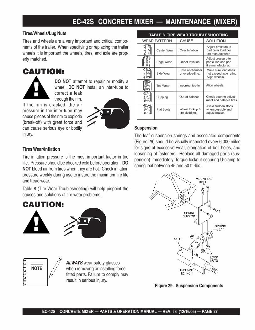
EC-42S CONCRETE MIXER — MAINTENANCE (MIXER)Tires/Wheels/Lug Nuts
Tires and wheels are a very important and critical compo-nents of the trailer. When specifying or replacing the trailerwheels it is important the wheels, tires, and axle are prop-erly matched.
DO NOT attempt to repair or modify awheel. DO NOT install an inter-tube tocorrect a leakthrough the rim.
If the rim is cracked, the airpressure in the inter-tube maycause pieces of the rim to explode(break-off) with great force andcan cause serious eye or bodilyinjury.
Tires Wear/Inflation
Tire inflation pressure is the most important factor in tirelife. Pressure should be checked cold before operation. DONOT bleed air from tires when they are hot. Check inflationpressure weekly during use to insure the maximum tire lifeand tread wear.
Table 8 (Tire Wear Troubleshooting) will help pinpoint thecauses and solutions of tire wear problems.
ALWAYS wear safety glasseswhen removing or installing forcefitted parts. Failure to comply mayresult in serious injury.
Figure 29. Suspension Components
Suspension
The leaf suspension springs and associated components(Figure 29) should be visually inspected every 6,000 milesfor signs of excessive wear, elongation of bolt holes, andloosening of fasteners. Replace all damaged parts (sus-pension) immediately. Torque locknut securing U-clamp tospring leaf between 45 and 50 ft.-lbs.
CAUTION:
NOTE
CAUTION:CAUTION:CAUTION:CAUTION:CAUTION:

PAGE 28 — EC-42S CONCRETE MIXERS — PARTS & OPERATION MANUAL — REV. #8 (12/16/05)
Lug Nut Torque Requirements
It is extremely important to apply and maintain proper wheelmounting torque on the trailer. Be sure to use only the fas-teners matched to the cone angle of the wheel. Proper pro-cedure for attachment of the wheels is as follows:
1. Start all wheel lug nuts by hand.
2. Torque all lug nuts in sequence. See Figure 30. DO NOTtorque the wheel lug nuts all the way down. Tighten each lugnut in 3 separate passes as defined by Table 10.
3. After first road use, retorque all lug nuts in sequence. Checkall wheel lug nuts periodically.
NEVER! use an pneumatic air gunto tighten wheel lug nuts.
Figure 30. Wheel Lug Nuts Tightening Sequence
NOTE
Mixer Storage
For storage of the mixer for over 30 days, the following isrecommended:
Drain the fuel tank completely, or add STA-BIL to thefuel.
Run the engine until the fuel is completely consumed.
Completely drain used oil from the engine crankcaseand fill with fresh clean oil, then follow the proceduresdescribed in the engine manual for engine storage.
Clean the entire mixer and engine compartment.
Place the mixing drum in the down position (mouth facingdownward).
Cover the mixer and place it a clean dry area, that isprotected from harsh elements.
EC-42S CONCRETE MIXER — MAINTENANCE (MIXER)

EC-42S CONCRETE MIXER — PARTS & OPERATION MANUAL — REV. #8 (12/16/05) — PAGE 29
NOTE PAGE

PAGE 30 — EC-42S CONCRETE MIXERS — PARTS & OPERATION MANUAL — REV. #8 (12/16/05)
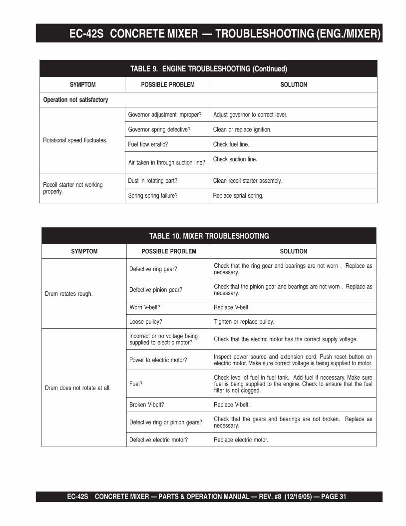
EC-42S CONCRETE MIXER — TROUBLESHOOTING (ENGINE)Practically all breakdowns can be prevented by properhandling and maintenance inspections, but in the event of abreakdown, please take a remedial action following the
diagnosis based on the Troubleshooting (Tables 9 and 10)information shown below and on the next page. If the problemcannot be remedied, please leave the unit just as it is andconsult our company's business office or service plant.
GNITOOHSELBUORTENIGNE.9ELBAT
MOTPMYS MELBORPELBISSOP NOITULOS
tratsottluciffiD
gulpkrapstubelbaliavasileuFtaelbaliavarewoP(.etingitonlliw
.)elbacnoisnethgih
?egdirbgniebgulpnoitingI .metsysnoitingikcehC
?noitingitatisopednobraC .noitingiecalperronaelC
evitcefedoteudtiucrictrohS?srotalusni
.srotalusniecalpeR
?pagkrapsreporpmI .pagtcerrocehtotpaggulpkrapsteS
gulpkrapstubelbaliavasileuFrewoP(.etingitonlliw TON
.)elbacnoisnethgihtaelbaliava
?hctiwspotstatiucrictrohS .evitcefedfihctiwspotsecalpeR.tiucrichctiwspotskcehC
?evitcefedliocnoitingI .liocnoitingiecalpeR
gulpkrapsdnaelbaliavasileuFnoisserpmoc(setingi )lamron .
nobrachtiwdeggolcrelffuM?stisoped
.relffumecalperronaelC
,retaw(etauqedaniesunileuF?)tsud
.leufhserfhtiwecalperdnametysleufhsulF
?deggolcrenaelCriA .renaelcriaecalperronaelC
gulpkrapsdnaelbaliavasileuFnoisserpmoc(setingi wol .)
?teksagdaehrednilycevitcefeD .teksagdaehecalperrostlobdaehrednilycnethgiT
?nrowrednilyC .rednilycecalpeR
?esoolgulpkrapS .gulpkrapsnehgiT
yrotcafsitastonnoitarepO
elbaliavarewophguonetoN-ssimon,lamronnoisserpmoc(
.)gnirif
?deggolcrenaelcriA
?enilleufniriA .enilleufmorf)riaevomer(deelB
taolfrotaerubracnilevelleuF?reporpmirebmahc taolfrotaerubractsujdA
?rednilycnistisopednobraC rednilycecalperronaelC
elbaliavarewophguonetoN-ssim,lamronnoisserpmoc(
.)gnirif
?evitcefedliocnoitingI .leufhserfhtiwecalperdnametysleufhsulF
?strohsnetfogulpnoitingI .noitinginaelc,seriwnoitingiecalpeR
,retaw(etauqedaniesunileuF?)tsud
.leufhserfhtiwecalperdnametysleufhsulF
.staehrevoenignE
ninoitsopednobracevissecxE?rebmahcnoitsubmoc
.esacknarcecalperronaelC
htiwdeggolcrelffumrotsuahxE.nobrac
.relffumecalperronaelC
?tcerrocnieulavtaehgulpkrapS .gulpkrapsepyttcerrochtiwgulpkrapsecalpeR
EC-42S CONCRETE MIXER — PARTS & OPERATION MANUAL — REV. #8 (12/16/05) — PAGE 31
EC-42S CONCRETE MIXER — TROUBLESHOOTING (ENG./MIXER)
)deunitnoC(GNITOOHSELBUORTENIGNE.9ELBAT
MOTPMYS MELBORPELBISSOP NOITULOS
yrotcafsitastonnoitarepO
.setautculfdeepslanoitatoR
?reporpmitnemtsujdaronrevoG .reveltcerrocotronrevogtsujdA
?evitcefedgnirpsronrevoG .noitingiecalperronaelC
?citarrewolfleuF .enilleufkcehC
?enilnoitcushguorhtninekatriA .enilnoitcuskcehC
gnikrowtonretratslioceR.ylreporp
?trapgnitatornitsuD .ylbmessaretratsliocernaelC
?eruliafgnirpsgnirpS .gnirpslairpsecalpeR
GNITOOHSELBUORTREXIM.01ELBAT
MOTPMYS MELBORPELBISSOP NOITULOS
.hguorsetatormurD
?raeggnirevitcefeD saecalpeR.nrowtonerasgniraebdnaraeggnirehttahtkcehC.yrassecen
?raegnoinipevitcefeD saecalpeR.nrowtonerasgniraebdnaraegnoinipehttahtkcehC.yrassecen
?tleb-VnroW .tleb-VecalpeR
?yellupesooL .yellupecalperronethgiT
.llataetatortonseodmurD
gniebegatlovonrotcerrocnI?rotomcirtceleotdeilppus .egatlovylppustcerrocehtsahrotomcirtceleehttahtkcehC
?rotomcirtceleotrewoP nonottubteserhsuP.drocnoisnetxednaecruosrewoptcepsnI.rotomotdeilppusgniebsiegatlovtcerrocerusekaM.rotomcirtcele
?leuFerusekaM.yrassecenfileufddA.knatleufnileuffolevelkcehCleufehttahterusneotkcehC.enigneehtotdeilppusgniebsileuf
.deggolctonsiretlif
?tleb-VnekorB .tleb-VecalpeR
?sraegnoiniprognirevitcefeD saecalpeR.nekorbtonerasgniraebdnasraegehttahtkcehC.yrassecen
?rotomcirtceleevitcefeD .rotomcirtceleecalpeR
PAGE 32 — EC-42S CONCRETE MIXERS — PARTS & OPERATION MANUAL — REV. #8 (12/16/05)
How to read the marks and remarks used in this partsbook.
Items Found In the “Remarks” Column
Serial Numbers-Where indicated, this indicates a serialnumber range (inclusive) where a particular part is used.
Model Number-Where indicated, this shows that thecorresponding part is utilized only with this specific modelnumber or model number variant.
Items Found In the “Items Number” ColumnAll parts with same symbol in the number column, *, #, +, %, or>, belong to the same assembly or kit.
The contents of this partscatalog are subject to changewithout notice.
If more than one of the samereference number is listed, thelast one listed indicates newest(or latest) part available.
NOTE
NOTE
EXPLANATION OF CODE IN REMARKS COLUMN
EC-42S CONCRETE MIXER — PARTS & OPERATION MANUAL — REV. #8 (12/16/05) — PAGE 33
EC-42S CONCRETE MIXER — SUGGESTED SPARE PARTS
EC-42S CONCRETE MIXER 1 TO 4 UNITS WITHHONDA GX120K1QX2Qty. P/N Description2 ....... 491115 ................ V-BELT1 ....... EM940734 ........... STOP BUTTON w/GAS ENGINE2 ....... 491010 ................ LATCH SET1 ....... 505390 ................ EXPANSION PLUG2 ....... EM903026 ........... SPINDLE BEARING CUP2 ....... EM903063 ........... SPINDLE BEARING CONES1 ....... EM505472 ........... SPACER, DRUM2 ....... 492179 ................ BEARING JACKSHAFT2 ....... EM914288 ........... SEAL, AXLE2 ....... EM903012 ........... BEARING CUP2 ....... EM903049 ........... BEARING CONE, 7/8" SPINDLE2 ....... EM903113 ........... BEARING CONE, 1-1/16" SPINDLE2 ....... 3469 .................... DUST CAP, AXLE4 ....... 17210ZE0505 ...... ELEMENT, AIR CLEANER4 ....... 9807955846 ......... SPARK PLUG1 ....... 28462ZH8003 ...... ROPE, RECOIL STARTER
NOTEPart numbers on this SuggestedSpare Parts List may supercede/replace the P/N's shown in thetest pages of this manual.

PAGE 34 — EC-42S CONCRETE MIXERS — PARTS & OPERATION MANUAL — REV. #8 (12/16/05)
EC-42S CONCRETE MIXER — NAME PLATE AND DECALSNAME PLATE AND DECALS

EC-42S CONCRETE MIXER — PARTS & OPERATION MANUAL — REV. #8 (12/16/05) — PAGE 35
EC-42S CONCRETE MIXER— NAME PLATE AND DECALS
NAME PLATE AND DECALS
NO PART NO PART NAME QTY. REMARKS1 EM510891 DECAL, MQ ESSICK LOGO 32 CIPDCL160 DECAL, CRUSH WARNING 23 504713 DECAL, SAFETY INSTRUCTIONS 14 EM948630 DECAL, EMERGENCY STOP 15 DCL151 DECAL, TOWING INSTRUCTIONS 16 13118 DECAL, POWDER COATED 17 NAMEPLATE........................................................ 1 ......... CONTACT MQPARTS DEPT.
SEE OPERATION AND SAFETY DECALS PAGE.

PAGE 36 — EC-42S CONCRETE MIXERS — PARTS & OPERATION MANUAL — REV. #8 (12/16/05)
EC-42S — STEEL BARREL
STEEL BARREL ASSY.

EC-42S CONCRETE MIXER — PARTS & OPERATION MANUAL — REV. #8 (12/16/05) — PAGE 37
EC-42S — STEEL BARREL
STEEL BARREL ASSY.
NO PART NO PART NAME QTY. REMARK1 500904 CAP 12 501867 KING PIN 13 EM903054 SPINDLE BEARING 5/8" CONE ............ 2 ............. REPLACES 4921544 EM903017 SPINDLE BEARING CUP ...................... 2 ............. REPLACES 4922335 502427 RING GEAR 16 EM963610 BOLT 3/8" NC 1-1/4" G5 67 502449 BARREL, STEEL 4 CU. FT. 18 511732 SHIM 0.25 THICK AR8 511731 SHIM .187 THICK AR8 511730 SHIM .140 THICK AR9 EM969013 NUT, LOCK 3/8” NC 510 490956 RING, RETENTION 211 502019 DRIVE PINION SHAFT 112 493296 PINION SHAFT BEARING 213 EM963692 BOLT 1/2" NC X 1-1/2" G5 214 492584 LOCKNUT, HEX 1/2" NC 215 502018 HOUSING JACKSHAFT 116 491008 CAP, GREASE FITTING 317 EM916001 GREASE FITTING 1/8" NPT ................. 3.............. REPLACES 49169818 500214 SQUARE KEY 1/4" X 30 MM 119 501917 DRIVE PINION 120 492467 ALLEN SCREW 5/16 NC 3/8" 121 EM505472 SPACER, BARREL 122 492483 SET SCREW 3/8" X 1- 1/4" NC 123 500601 NUT, HEX LOWER 1" ............................ 1 ............. REPLACES 49257924 EM963102 BOLT 1/2" NC X 1-1/4" NC 225 492584 LOCKNUT, HEX 1/2" NC 226 502016 YOKE 127 491685 COTTER PIN 3/32" X 2" 128 500601 CASTLE NUT 1" 129 501269 SPACER 1

PAGE 38 — EC-42S CONCRETE MIXERS — PARTS & OPERATION MANUAL — REV. #8 (12/16/05)
EC-42S — MAIN FRAME ASSEMBLY
MAIN FRAME ASSY.
EC-42S CONCRETE MIXER — PARTS & OPERATION MANUAL — REV. #8 (12/16/05) — PAGE 39
EC-42S — MAIN FRAME ASSEMBLY
MAIN FRAME ASSY.
NO PART NO PART NAME QTY. REMARK1 501844 GUARD, GEAR WHEEL 12 2101402 WASHER, LOCK 1/4" 43 492284 ROUND HEAD BOLT 1/4" NC 3/8 G2" ......... 4.............. REPLACES 4922794 502017 DUMP GEAR 15 EM969013 NUT, LOCK 3/8" NC 16 490896 DUMP LATCH 17 EM963610 BOLT 3/8" NC X 1-1/2" G5 18 EM916001 GREASE FITTING 1/8" NPT ........................ 2.............. REPLACES 4916989 491008 GREASE CAP 210 EM963055 ALLEN BOLT 3/16" NS X 5/8" 411 492621 WASHER, LOCK 3/16" 412 495595 WASHER, FLAT 3/16" 413 502448 FRAME 114 10176 LOCK NUT 1/2 NC........................................ 1.............. REPLACES 49258615 EM124 BOLT 1/2"- 13 X 4 G5 116 500596 HANDWHEEL SHAFT 117 501902 HANDWHEEL 118* SAFETY CHAIN ....................................... 1 ............ REPLACES 1336319* 01004 CONNECTOR LINK 220 490958 RING RETAINING 121 13363KIT CHAIN LINK KIT ........................................... 1.............. INCLUDES ITEMS W/*22 HBC-1 BALL HITCH 2-INCH .................................... 1.............. CONTACT UNIT SALES23 HLC-1 LOOP HITCH ................................................ 1.............. CONTACT UNIT SALES24 HPC-1 PIN HITCH 1-INCH ....................................... 1.............. CONTACT UNIT SALES

PAGE 40 — EC-42S CONCRETE MIXERS — PARTS & OPERATION MANUAL — REV. #8 (12/16/05)
EC-42S — AXLE ASSEMBLYAXLE ASSY.
EC-42S CONCRETE MIXER — PARTS & OPERATION MANUAL — REV. #8 (12/16/05) — PAGE 41
EC-42S — AXLE ASSEMBLY
AXLE ASSY.
NO PART NO PART NAME QTY. REMARK1 EM969023 LOCK NUT 5/8" NC 42 4922406 BOLT 5/8" NC 1-1/2" G5 43*# EM914288 OIL SEAL 24* EM903049 BEARING CONE, (7/8" SPINDLE) 44# EM903113 BEARING CONE, (1-1/16" SPINDLE) 45*# EM903012 BEARING CUP 46 3504 HUB ASSY., 4-BOLT (7/8" SPINDLE) ............................. 2 ........... INCLUDES ITEMS W/*
....................................................................................................... REPLACES 4932356 EM941306 HUB ASSY., 4-BOLT (1-1/16" SPINDLE) ........................ 2 ........... INCLUDES ITEMS W/#7 EM511159 WASHER, FLAT, .087" THICKNESS 28 EM501299 WASHER, FLAT, .135" THICKNESS AR9 491688 COTTER PIN 1/8" X 1-1/2' 210 12426 NUT, SLOTTED HEX JAM 3/4"- 20 ................................. 210 8164 NUT, SLOTTED HEX JAM 3/4"- 20 211 3005 TIRE AND RIM, CARLISE 211 493236C TIRE AND RIM, UNIROYAL 212*# 8115 LUG NUTS 813*# 3469 DUST CAP 214 501960 AXLE 7/8" SPINDLE 114 511335 AXLE 1-1/16 SPINDLE 1
PAGE 42 — EC-42S CONCRETE MIXERS — PARTS & OPERATION MANUAL — REV. #8 (12/16/05)
EC-42S — CABINET ASSEMBLY
CABINET ASSY.

EC-42S CONCRETE MIXER — PARTS & OPERATION MANUAL — REV. #8 (12/16/05) — PAGE 43
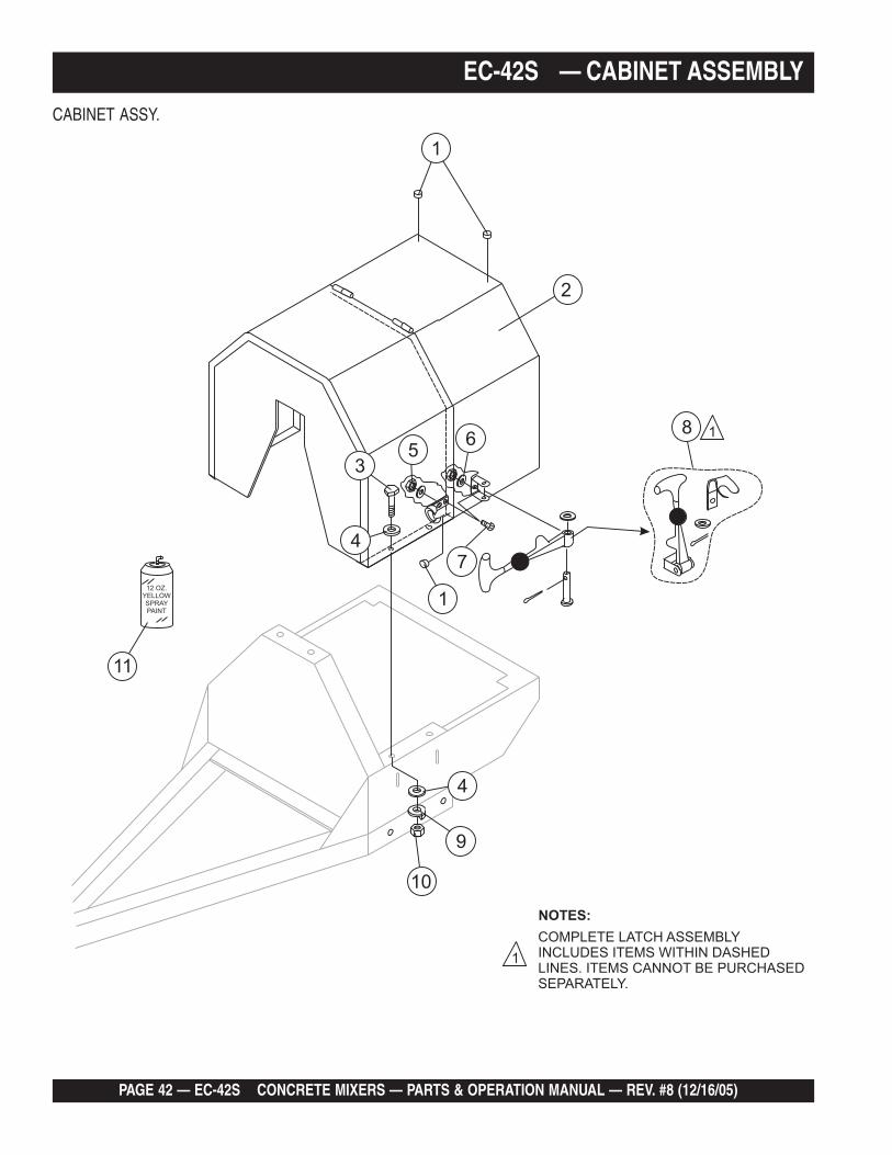
EC-42S — CABINET ASSEMBLYCABINET ASSY.
NO PART NO PART NAME QTY. REMARKS1 490202 RUBBER PROTECTOR 42 501954 ENGINE HOUSING CABINET, W/DECALS ............. 1 ............ INCLUDES ITEM W/*3 492363 BOLT 5/16" NC X 3/4" G5 44 EM923023 WASHER, FLAT 5/16" 85 13287 LOCK NUT 8-32 ....................................................... 6 ............REPLACEMENT PART ONLY6 2203 WASHER, FLAT #10 ................................................ 6 ............REPLACEMENT PART ONLY7 1307 RHMS 8-32 X 1/2" .................................................... 6 ............REPLACEMENT PART ONLY8* 491010 LATCH ASSY., COMPLETE 29 EM923343 WASHER, LOCK 5/16" 410 2105164 NUT 5/16" NC G5 411 EM947007 PAINT, SPRAY CAN 12 OZ. TRAFFIC RED AR

PAGE 44 — EC-42S CONCRETE MIXERS — PARTS & OPERATION MANUAL — REV. #8 (12/16/05)
EC-42S — GAS ENGINE MOUNTING PLATE ASSEMBLY
GAS ENGINE MOUNTING PLATE ASSY.
EC-42S CONCRETE MIXER — PARTS & OPERATION MANUAL — REV. #8 (12/16/05) — PAGE 45
EC-42S — GAS ENGINE MOUNTING PLATE ASSEMBLY
GAS ENGINE MOUNTING PLATE ASSY.
NO PART NO PART NAME QTY. REMARKS1 GX120K1QX2 ENGINE, HONDA 4.0 HP 12 490956 RING, RETAINING 13 500246 SQUARE KEY 14 EM961045 SET SCREW 5/16" NC X 3/4" 15 492066 UPPER PULLEY 16 501019 SQUARE KEY 3/16" X 45 MM 17 491115 V-BELT A-46 18 492467 ALLEN SCREW 5/16" NC X 3/8" 19 492065 DRIVE PULLEY 4.0 HP 110 EM923343 WASHER, LOCK 5/16" 411 EM923023 WASHER, FLAT 5/16" 412 2105164 NUT, HEX 5/16 X18 NC G5 413 502023 BASE PLATE ENGINE 114 492600 WASHER, FLAT 1/2" 815 EM963692 BOLT, HEX 1/2" NC 1-1/2" G5 416 29174-001 BUTTON, STOP 117 EM940734 SWITCH, STOP ........................................... 1 ........... REPLACES 49184518 503600 ENGINE CABLE HARNESS 119 492584 LOCKNUT 1/2" 420 492367 BOLT 5/16" X 1-3/4" G5 4
PAGE 46 — EC-42S CONCRETE MIXERS — PARTS & OPERATION MANUAL — REV. #8 (12/16/05)
EC-42S — ELECTRIC MOTOR MOUNTING PLATE ASSEMBLY
ELECTRIC MOTOR MOUNTING PLATE ASSY.
EC-42S CONCRETE MIXER — PARTS & OPERATION MANUAL — REV. #8 (12/16/05) — PAGE 47
EC-42S — ELECTRIC MOTOR MOUNTING PLATE ASSEMBLY
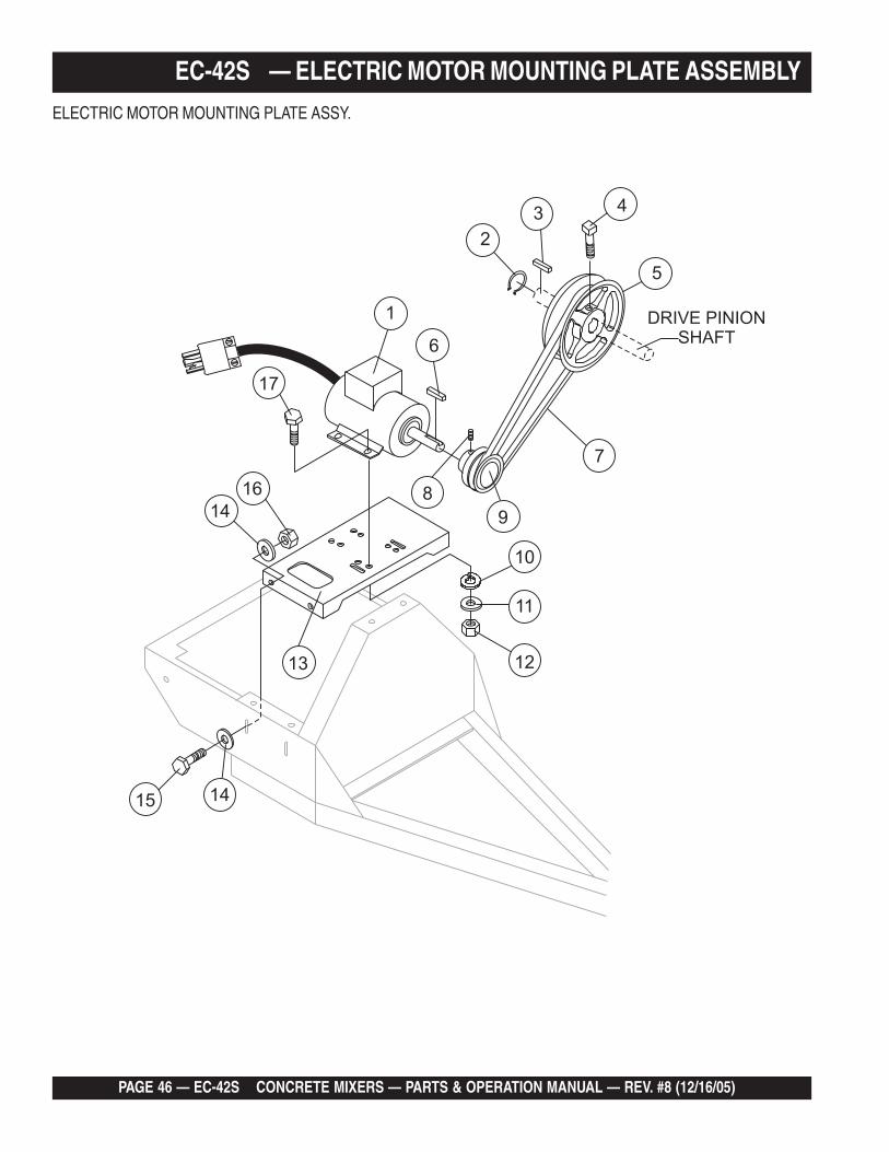
ELECTRIC MOTOR MOUNTING PLATE ASSY.
NO PART NO PART NAME QTY. REMARKS1 34F3245596 MOTOR, ELECTRIC .5 HP 12 490956 RING, RETAINING 13 500246 SQUARE KEY 14 EM961045 SET SCREW 5/16" NC X 3/4" 15 492066 UPPER PULLEY 16 501019 SQUARE KEY 3/16" X 45 MM 17 491115 V-BELT, A46 18 492467 ALLEN SCREW 5/16" NC X 1/2" 19 492067 DRIVE PULLEY 110 EM923343 WASHER, LOCK 5/16" 411 EM923023 WASHER, FLAT 5/16" 412 2105164 NUT, HEX 5/16 X18 NC G5 413 502023 BASE PLATE ENGINE 114 492600 WASHER, FLAT 1/2" 815 EM963692 BOLT, HEX 1/2" NC 1-1/2" G5 416 492584 LOCKNUT 1/2" 417 492367 BOLT 5/16" X 1-3/4" 4

PAGE 48 — EC-42S CONCRETE MIXERS — PARTS & OPERATION MANUAL — REV. #8 (12/16/05)
HONDA GX120K1QX2 — AIR CLEANER ASSY.AIR CLEANER ASSY.

EC-42S CONCRETE MIXER — PARTS & OPERATION MANUAL — REV. #8 (12/16/05) — PAGE 49
HONDA GX120K1QX2 — AIR CLEANER ASSY.AIR CLEANER ASSY.
NO. PART NO. PART NAME QTY. REMARKS1 16271ZE1000 GASKET, ELBOW 12 17210ZE0505 ELEMENT, AIR CLEANER (DUAL) ................... 1 ............. INCLUDES ITEMS W/*3* 17218ZE0505 FILTER, OUTER 14 17230ZE0820 COVER, AIR CLEANER (DUAL) 15* 17232891000 GROMMET, AIR CLEANER 17# 17238ZE0010 COLLAR, AIR CLEANER 28# 17239ZE1000 COLLAR B, AIR CLEANER 19 17410ZE0030 ELBOW, AIR CLEANER ................................... 1 ............. INCLUDES ITEMS W/#12 90325044000 WINGNUT, TOOL BOX SETTING 213 957010602000 BOLT, FLANGE 6X20 114 9405006000 NUT, FLANGE 6MM 2

PAGE 50 — EC-42S CONCRETE MIXERS — PARTS & OPERATION MANUAL — REV. #8 (12/16/05)
HONDA GX120K1QX2 — CAMSHAFT ASSY.CAMSHAFT ASSY.

EC-42S CONCRETE MIXER — PARTS & OPERATION MANUAL — REV. #8 (12/16/05) — PAGE 51
HONDA GX120K1QX2 — CAMSHAFT ASSY.CAMSHAFT ASSY.
NO. PART NO. PART NAME QTY. REMARKS1 14100ZE0812 CAMSHAFT ASSEMBLY .................................. 1 ............. INCLUDES ITEMS W/*2 14410ZE0010 ROD, PUSH 23 14431ZE1000 ARM, VALVE ROCKER 24 14441ZE1010 LIFTER, VALVE 25 14451ZE1013 PIVOT, ROCKER ARM 26* 14568ZE1000 SPRING, WEIGHT RETURN 17 14711ZF0010 VALVE, IN. 18 14721ZF0000 VALVE, EX. 19 14751ZF1000 SPRING, VALVE 210 14771ZE1000 RETAINER, IN. VALVE SPRING 111 14773ZE1000 RETAINER, EX. VALVE SPRING 112 14781ZE1000 ROTATOR, VALVE 113 14791ZE0010 PLATE, PUSH ROD GUIDE 114 90012ZE0010 BOLT, PIVOT 8MM 215 90206ZE1000 NUT, PIVOT ADJ. 2

PAGE 52 — EC-42S CONCRETE MIXERS — PARTS & OPERATION MANUAL — REV. #8 (12/16/05)
CARBURETOR ASSY.
HONDA GX120K1QX2 — CARBURETOR ASSY.

EC-42S CONCRETE MIXER — PARTS & OPERATION MANUAL — REV. #8 (12/16/05) — PAGE 53
HONDA GX120K1QX2 — CARBURETOR ASSY.
HONDA GX120K1QX2 — CARBURETOR ASSY.CARBURETOR ASSY.
NO. PART NO. PART NAME QTY. REMARKS1* 16010ZE1812 GASKET SET 12* 16011ZE0005 VALVE SET, FLOAT 13* 16013ZE0005 FLOAT SET 14* 16015ZE1811 CHAMBER SET, FLOAT 15* 16016ZH7W01 SCREW SET 16* 16024ZE1811 SCREW SET, DRAIN 17* 16028ZE0005 SCREW SET B 18* 16044ZE0005 CHOKE SET 19 16100ZH7W51 CARBURETOR ASSEMBLY, BE60B B ............. 1 ............. INCLUDES ITEMS W/*10* 16124ZE0005 SCREW, THROTTLE STOP 111* 16166ZH7W50 NOZZLE, MAIN 112* 160756HBB00 GASKET, FUEL STRAINER CUP 113 16211ZE0000 INSULATOR, CARBURETOR 114 16212ZH7800 GASKET, INSULATOR 115 16220ZE1020 SPACER, CARBURETOR 116 16221ZH8801 GASKET, CARBURETOR 117 16610ZE1000 LEVER, CHOKE (STANDARD) ......................... 1 ............. INCLUDES ITEMS W/#18* 16953ZE1812 LEVER,VALVE 119* 16954ZE1811 PLATE, LEVER SETTING 120* 16956ZE1811 SPRING, VALVE LEVER 121* 16957ZE1812 GASKET, VALVE 122* 16967ZE0811 CUP, FUEL STRAINER 123* 93500030080G SCREW, PAN (3 X 6) 224# 9430520122 PIN, SPRING (2 X 12) 125 99101ZH80550 JET, MAIN (#55) (OPTIONAL) 125 99101ZH80580 JET, MAIN (#58) (OPTIONAL) 125* 99101ZH80600 JET, MAIN (#60) 126* 99204ZE00350 JET, SET, PILOT (#35) 1
PAGE 54 — EC-42S CONCRETE MIXERS — PARTS & OPERATION MANUAL — REV. #8 (12/16/05)
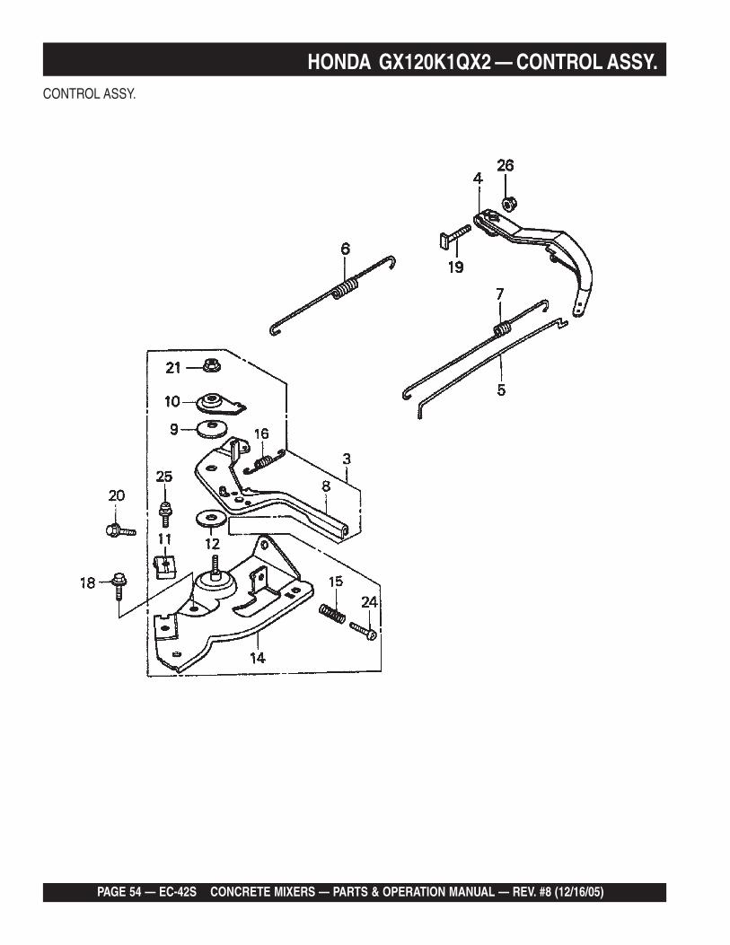
CONTROL ASSY.
HONDA GX120K1QX2 — CONTROL ASSY.

EC-42S CONCRETE MIXER — PARTS & OPERATION MANUAL — REV. #8 (12/16/05) — PAGE 55
HONDA GX120K1QX2 — CONTROL ASSY.CONTROL ASSY.
NO. PART NO. PART NAME QTY. REMARKS3 16500ZH7820 CONTROL ASSEMBLY (REMOTE) ........... 1 ............ INCLUDES ITEMS W/#4 16551ZE0010 ARM, GOVERNOR 15 16555ZE0000 ROD, GOVERNOR 16 16561ZE0020 SPRING, GOVERNOR 17 16562ZE0020 SPRING, THROTTLE RETURN 18# 16571ZH7000 LEVER, CONTROL 19# 16574ZE1000 SPRING, LEVER 110# 16575ZH8000 WASHER, CONTROL LEVER 111# 16576891000 HOLDER, CABLE12# 16578ZE1000 SPACER, CONTROL LEVER 114# 16580ZH7810 BASE CONTROL 115# 16584883300 SPRING, CONTROL ADJUSTING 116# 16592ZE1810 SPRING, CABLE RETURN18 90013883000 BOLT, FLANGE 6X12 (CT200) 119 90015ZE5010 BOLT, GOVERNOR ARM 120 90022888010 BOLT, FLANGE 6X20 (CT200) 121# 90114SA0000 NUT, SELF- LOCK 6MM 124# 93500050250H SCREW, PAN 5X25 125# 0202005T125 SCREW, PAN 126 9405006000 NUT, FLANGE 6MM 1

PAGE 56 — EC-42S CONCRETE MIXERS — PARTS & OPERATION MANUAL — REV. #8 (12/16/05)
CRANKCASE COVER ASSY.
HONDA GX120K1QX2 — CRANKCASE COVER ASSY.

EC-42S CONCRETE MIXER — PARTS & OPERATION MANUAL — REV. #8 (12/16/05) — PAGE 57
HONDA GX120K1QX2 — CRANKCASE COVER ASSY.CRANKCASE COVER ASSY.
NO. PART NO. PART NAME QTY. REMARKS1 11300ZE0640 COVER ASSEMBLY, CRANKCASE (W- TYPE) ....... 1 .............. INCLUDES ITEMS W/*2 11381ZH7800 GASKET, CASE COVER 13 15600ZE1003 CAP ASSEMBLY, OIL FILLER ................................ 1 .............. INCLUDES ITEMS W/#4 15600ZG4003 CAP ASSEMBLY, OIL FILLER ................................ 1 .............. INCLUDES ITEMS W/#7# 15625ZE1003 GASKET, OIL FILLER CAP 19 90015883000 BOLT, FLANGE 6X28 710* 91001878003 BEARING, RADIAL BALL 111* 91203ZE0013 OIL SEAL 22X41X6 112 9430108140 PIN A, DOWEL 8X14 2

PAGE 58 — EC-42S CONCRETE MIXERS — PARTS & OPERATION MANUAL — REV. #8 (12/16/05)
CRANKSHAFT ASSY.
HONDA GX120K1QX2 — CRANKSHAFT ASSY.

EC-42S CONCRETE MIXER — PARTS & OPERATION MANUAL — REV. #8 (12/16/05) — PAGE 59
HONDA GX120K1QX2 — CRANKSHAFT ASSY.CRANKSHAFT ASSY.
NO. PART NO. PART NAME QTY. REMARKS1 13310ZE0601 CRANKSHAFT, H-TYPE 12 90745ZE1600 KEY 4.78 X4.78X38 1

PAGE 60 — EC-42S CONCRETE MIXERS — PARTS & OPERATION MANUAL — REV. #8 (12/16/05)
CYLINDER BARREL ASSY.
HONDA GX120K1QX2 — CYLINDER BARREL ASSY.
EC-42S CONCRETE MIXER — PARTS & OPERATION MANUAL — REV. #8 (12/16/05) — PAGE 61
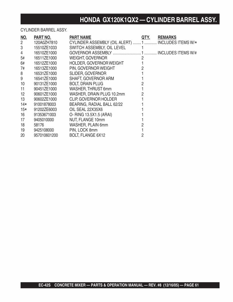
HONDA GX120K1QX2 — CYLINDER BARREL ASSY.CYLINDER BARREL ASSY.
NO. PART NO. PART NAME QTY. REMARKS2 120A0ZH7810 CYLINDER ASSEMBLY (OIL ALERT) ........1 ............ INCLUDES ITEMS W/*3 15510ZE1033 SWITCH ASSEMBLY, OIL LEVEL 14 16510ZE1000 GOVERNOR ASSEMBLY ...........................1 ............ INCLUDES ITEMS W/#5# 16511ZE1000 WEIGHT, GOVERNOR 26# 16512ZE1000 HOLDER, GOVERNOR WEIGHT 17# 16513ZE1000 PIN, GOVERNOR WEIGHT 28 16531ZE1000 SLIDER, GOVERNOR 19 16541ZE1000 SHAFT, GOVERNOR ARM 110 90131ZE1000 BOLT, DRAIN PLUG 211 90451ZE1000 WASHER, THRUST 6mm 112 90601ZE1000 WASHER, DRAIN PLUG 10.2mm 213 90602ZE1000 CLIP, GOVERNOR HOLDER 114* 91001878003 BEARING, RADIAL BALL 62/22 115* 91202ZE6003 OIL SEAL 22X35X6 116 91353671003 O- RING 13.5X1.5 (ARAI) 117 9405010000 NUT, FLANGE 10mm 118 58176 WASHER, PLAIN 6mm 219 9425108000 PIN, LOCK 8mm 120 957010601200 BOLT, FLANGE 6X12 2

PAGE 62 — EC-42S CONCRETE MIXERS — PARTS & OPERATION MANUAL — REV. #8 (12/16/05)
CYLINDER HEAD ASSY.
HONDA GX120K1QX2 — CYLINDER HEAD ASSY.

EC-42S CONCRETE MIXER — PARTS & OPERATION MANUAL — REV. #8 (12/16/05) — PAGE 63
HONDA GX120K1QX2 — CYLINDER HEAD ASSY.CYLINDER HEAD ASSY.
NO. PART NO. PART NAME QTY. REMARKS1 12210ZH7000 CYLINDER HEAD .................................................. 1 .............. INCLUDES ITEMS W/*2* 12204ZE1306 GUIDE, VALVE (OS) OPTIONAL 13* 12205ZE1315 GUIDE, EX. VALVE (OS) OPTIONAL ................... 1 .............. INCLUDES ITEMS W/+4*+ 12216ZE5300 CLIP, VALVE GUIDE 15 12251ZH7800 GASKET, CYLINDER HEAD 16 12310ZE1020 COVER, HEAD 17 12391ZE1000 GASKET, CYLINDER HEAD COVER 18 15721ZH8000 TUBE, BREATHER 19 90013883000 BOLT, FLANGE 6X12 (CT200) 410 90043ZE1020 BOLT, STUD 6X10⁹ 211 90047ZE1000 BOLT, STUD 8X32 212 9430110160 PIN, A, DOWEL 10X16 214 957230805500 BOLT, FLANGE 8X55 415 9807955846 SPARK PLUG BPR6ES (NGK) 1

PAGE 64 — EC-42S CONCRETE MIXERS — PARTS & OPERATION MANUAL — REV. #8 (12/16/05)
FAN COVER ASSY.
HONDA GX120K1QX2 — FAN COVER ASSY.
EC-42S CONCRETE MIXER — PARTS & OPERATION MANUAL — REV. #8 (12/16/05) — PAGE 65
HONDA GX120K1QX2 — FAN COVER ASSY.FAN COVER ASSY.
NO. PART NO. PART NAME QTY. REMARKS1 11347371300 GROMMET, ADJUSTING COVER 12 19610ZE0000ZE COVER, FAN *NH1* BLACK 13 19611ZH7810 PLATE, SIDE (OIL ALERT) 14 90601ZH7013 CLIP, HARNESS 15 19630ZH7000 SHROUD 16 32197ZH8003 SUB- HARNESS 17 36100ZE1015 SWITCH ASSEMBLY, ENGINE STOP 17 36100ZH7003 SWITCH ASSEMBLY, ENGINE STOP 18 36101ZE1010 WIRE, STOP SWITCH 370MM 19 90013883000 BOLT, FLANGE 6X12 (CT200) 610 90022888010 BOLT, FLANGE 6X12 (CT200) 111 34150ZH7003 ALERT UNIT, OIL 113 957010600800 BOLT, FLANGE 6X8 1

PAGE 66 — EC-42S CONCRETE MIXERS — PARTS & OPERATION MANUAL — REV. #8 (12/16/05)
FLYWHEEL ASSY.
HONDA GX120K1QX2 — FLYWHEEL ASSY.

EC-42S CONCRETE MIXER — PARTS & OPERATION MANUAL — REV. #8 (12/16/05) — PAGE 67
HONDA GX120K1QX2 — FLYWHEEL ASSY.FLYWHEEL ASSY.
NO. PART NO. PART NAME QTY. REMARKS1 13331357000 KEY, SPECIAL WOODRUFF 25X18 12 19511ZE0000 FAN, COOLING 14 28451ZH8003 PULLEY, STARTER 15 31100ZE0010 FLYWHEEL 17 90201878003 NUT, SPECIAL 14MM 1

PAGE 68 — EC-42S CONCRETE MIXERS — PARTS & OPERATION MANUAL — REV. #8 (12/16/05)
FUEL TANK ASSY.
HONDA GX120K1QX2 — FUEL TANK ASSY.

EC-42S CONCRETE MIXER — PARTS & OPERATION MANUAL — REV. #8 (12/16/05) — PAGE 69
HONDA GX120K1QX2 — FUEL TANK ASSY.FUEL TANK ASSY.
NO. PART NO. PART NAME QTY. REMARKS1 16854ZH8000 RUBBER, SUPPORTER 107MM 12 16955ZE1000 JOINT, FUEL TANK 13 17510ZE0020ZD TANK, FUEL *NH1* (BLACK) 15 17620ZH7023 CAP, FUEL FILLER ..................................... 1 .......... INCLUDES ITEMS W/*6* 17631ZH7003 GASKET, FUEL FILLER CAP 111 91353671003 O- RING 13.5X1.5 (ARAI) 112 9405006000 NUT, FLANGE 6MM 213 950014500360M BULK HOSE, FUEL (4.5X3000) (4.5X140) 114 9500202080 CLIP, TUBE (B8) 215 90004ZH7003 BOLT, FLANGE 6X29 1
PAGE 70 — EC-42S CONCRETE MIXERS — PARTS & OPERATION MANUAL — REV. #8 (12/16/05)
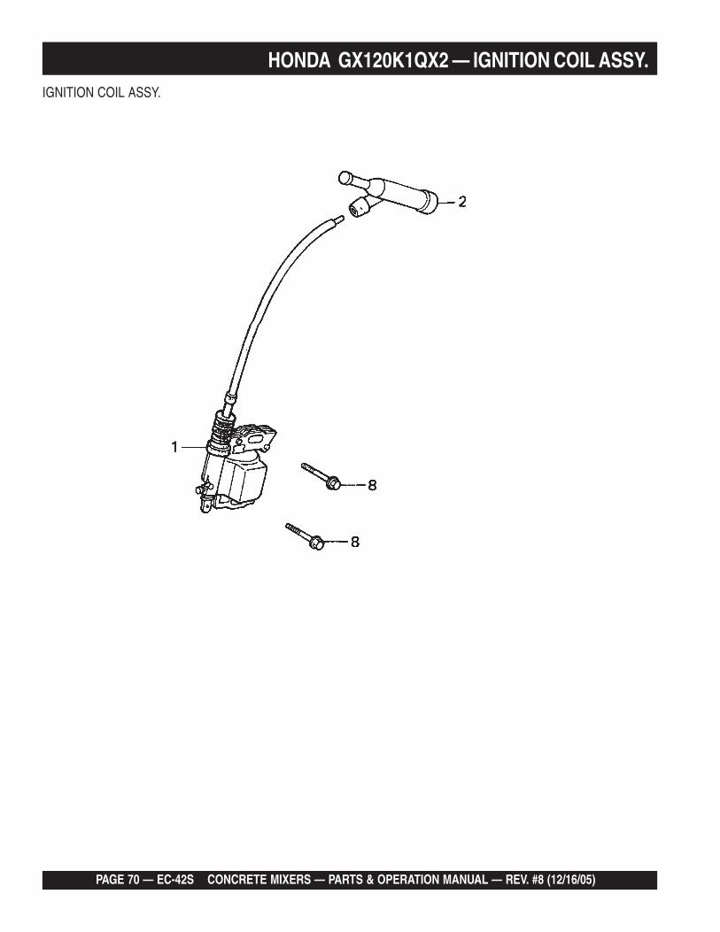
IGNITION COIL ASSY.
HONDA GX120K1QX2 — IGNITION COIL ASSY.

EC-42S CONCRETE MIXER — PARTS & OPERATION MANUAL — REV. #8 (12/16/05) — PAGE 71
HONDA GX120K1QX2 — IGNITION COIL ASSY.IGNITION COIL ASSY.
NO. PART NO. PART NAME QTY. REMARKS1 30500ZE1043 COIL ASSEMBLY, IGNITION 12 30700ZE1013 CAP ASSEMBLY, NOISE SUPPRESSOR 18 957010602500 BOLT, FLANGE 6X25 2
PAGE 72 — EC-42S CONCRETE MIXERS — PARTS & OPERATION MANUAL — REV. #8 (12/16/05)
MUFFLER ASSY.
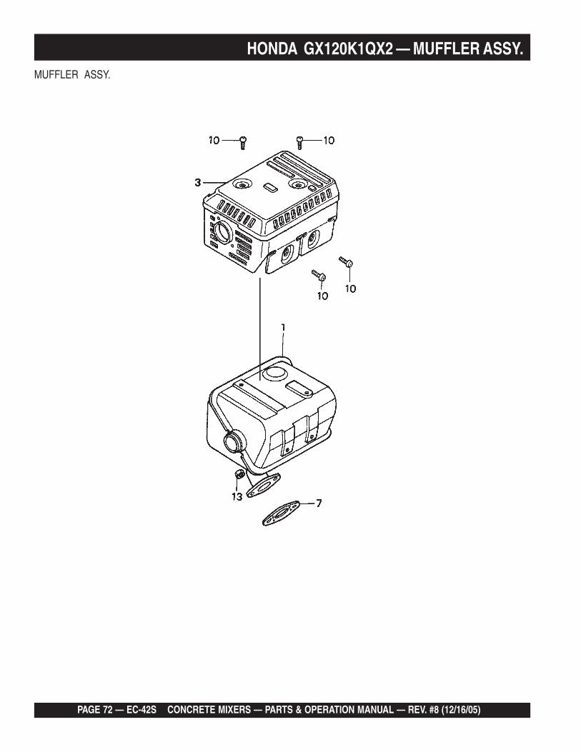
HONDA GX120K1QX2 — MUFFLER ASSY.

EC-42S CONCRETE MIXER — PARTS & OPERATION MANUAL — REV. #8 (12/16/05) — PAGE 73
HONDA GX120K1QX2 — MUFFLER ASSY.MUFFLER ASSY.
NO. PART NO. PART NAME QTY. REMARKS1 18310ZF1000 MUFFLER 13 18320ZF1H01 PROTECTOR, MUFFLER 17 18381ZH8800 GASKET, MUFFLER 110 90050ZE1000 SCREW, TAPPING 5X8 413 020108060 NUT, HEX. 8MM 2

PAGE 74 — EC-42S CONCRETE MIXERS — PARTS & OPERATION MANUAL — REV. #8 (12/16/05)
PISTON ASSY.
HONDA GX120K1QX2 — PISTON ASSY.

EC-42S CONCRETE MIXER — PARTS & OPERATION MANUAL — REV. #8 (12/16/05) — PAGE 75
HONDA GX120K1QX2 — PISTON ASSY.PISTON ASSY.
NO. PART NO. PART NAME QTY. REMARKS1 13010ZK7V02 RING SET, PISTON (STANDARD) 11 13011ZE6013 RING SET, PISTON (OS 0.25), OPTIONAL 11 13012ZK7V01 RING SET, PISTON (OS 0.50) , OPTIONAL 11 13013ZK7V01 RING SET, PISTON (OS 0.75), OPTIONAL 12 13101ZH7000 PISTON, STANDARD 12 13102ZH7000 PISTON, OS 0.25 12 13103ZH7000 PISTON, OS 0.50 12 13104ZH7000 PISTON, 0.75 13 13111ZE0000 PIN, PISTON 14 132A0ZE0000 ROD ASSY, CONNECTING (UNDER SIZE) .... 1 ...... INCLUDES ITEMS W/*4 13200ZE0000 ROD ASSEMBLY, CONNECTING.................... 1 ...... INCLUDES ITEMS W/*5* 90001ZE1000 BOLT, CONNECTING ROD 26 90551ZE0000 CLIP, PISTON PIN 13MM 2

PAGE 76 — EC-42S CONCRETE MIXERS — PARTS & OPERATION MANUAL — REV. #8 (12/16/05)
RECOIL STARTER ASSY.
HONDA GX120K1QX2 — RECOIL STARTER ASSY.

EC-42S CONCRETE MIXER — PARTS & OPERATION MANUAL — REV. #8 (12/16/05) — PAGE 77
HONDA GX120K1QX2 — RECOIL STARTER ASSY.RECOIL STARTER ASSY.
NO. PART NO. PART NAME QTY. REMARKS1 28400ZH8013ZB STARTER ASSY., RECOIL *NH1* (BLACK) .......... 1 .............. INCLUDES ITEMS W/*2* 28410ZH8003ZB CASE, RECOIL STARTER *NH1* (BLACK) 13* 28420ZH8013 REEL, RECOIL STARTER 14* 28422ZH8013 RATCHET, STARTER 25* 28433ZH8003 GUIDE, RATCHET 16* 28441ZH8003 SPRING, FRICTION 17* 28442ZH8003 SPRING, RECOIL STARTER 18* 28443ZH8003 SPRING, RETURN 29* 28461ZH8003 KNOB, RECOIL STARTER 110* 28462ZH8003 ROPE, RECOIL STARTER 111* 90003ZH8003 SCREW, SETTING 112 9008ZE2003 BOLT, FLANGE 6X10 3

PAGE 78 — EC-42S CONCRETE MIXERS — PARTS & OPERATION MANUAL — REV. #8 (12/16/05)
NO ARTWORK AVALIBLE
HONDA GX120K1QX2 ENGINE — GASKET KIT ASSY.

EC-42S CONCRETE MIXER — PARTS & OPERATION MANUAL — REV. #8 (12/16/05) — PAGE 79
GASKET KIT ASSY.
NO. PART NO. PART NAME QTY. REMARKS2 06111ZH7405 GASKET KIT ......................................................... 1 .............. INCLUDES ITEMS W/*3* 11381ZH7800 GASKET, CASE COVER 14* 12251ZH7800 GASKET, CYLINDER HEAD 15* 12391ZE1000 GASKET, CYLINDER HEAD COVER 16* 16212ZH7800 GASKET, INSULATOR 17* 16221ZH8801 GASKET, CARBURETOR 18* 18381ZH8800 GASKET, MUFFLER 1
HONDA GX120K1QX2 ENGINE — GASKET KIT ASSY.

PAGE 80 — EC-42S CONCRETE MIXERS — PARTS & OPERATION MANUAL — REV. #8 (12/16/05)
HONDA GX120K1QX2 — ENGINE LABELS ASSY.ENGINE LABELS ASSY.

EC-42S CONCRETE MIXER — PARTS & OPERATION MANUAL — REV. #8 (12/16/05) — PAGE 81
HONDA GX120K1QX2 — ENGINE LABELS ASSY.LABELS ASSY.
NO. PART NO. PART NAME QTY. REMARKS1 87521ZH7020 RING SET, PISTON (STANDARD) 13 87522zH9000 LABEL CAUTION 14 87528ZE1810 MARK CHOKE 16 87532ZH8810 MARK, OIL ALERT 1
PAGE 82 — EC-42S CONCRETE MIXERS — PARTS & OPERATION MANUAL — REV. #8 (12/16/05)
Multiquip reserves the right to quote and selldirect to Government agencies, and to OriginalEquipment Manufacturer accounts who useour products as integral parts of their ownproducts.
SPECIAL EXPEDITING SERVICE
A $35.00 surcharge will be added to the invoicefor special handling including bus shipments,insured parcel post or in cases where Multiquipmust personally deliver the parts to the carrier.
LIMITATIONS OF SELLER’S LIABILITY
Multiquip shall not be liable hereunder fordamages in excess of the purchase price of theitem with respect to which damages areclaimed, and in no event shall Multiquip beliable for loss of profit or good will or for anyother special, consequential or incidental dam-ages.
LIMITATION OF WARRANTIES
No warranties, express or implied, are madein connection with the sale of parts or tradeaccessories nor as to any engine not manufac-tured by Multiquip. Such warranties made inconnection with the sale of new, complete unitsare made exclusively by a statement of war-ranty packaged with such units, and Multiquipneither assumes nor authorizes any person toassume for it any other obligation or liabilitywhatever in connection with the sale of itsproducts. Apart from such written statement ofwarranty, there are no warranties, express,implied or statutory, which extend beyond thedescription of the products on the face hereof.
5. Parts must be in new and resalable con-dition, in the original Multiquip package (ifany), and with Multiquip part numbersclearly marked.
6. The following items are not returnable:
a. Obsolete parts. (If an item is in theprice book and shows as being re-placed by another item, it is obsolete.)
b. Any parts with a limited shelf life(such as gaskets, seals, “O” rings,and other rubber parts) that were pur-chased more than six months prior tothe return date.
c. Any line item with an extended dealernet price of less than $5.00.
d. Special order items.
e. Electrical components.
f. Paint, chemicals, and lubricants.
g. Decals and paper products.
h. Items purchased in kits.
7. The sender will be notified of any materialreceived that is not acceptable.
8. Such material will be held for five workingdays from notification, pending instruc-tions. If a reply is not received within fivedays, the material will be returned to thesender at his expense.
9. Credit on returned parts will be issued atdealer net price at time of the originalpurchase, less a 15% restocking charge.
10. In cases where an item is accepted, forwhich the original purchase documentcan not be determined, the price will bebased on the list price that was effectivetwelve months prior to the RMA date.
11. Credit issued will be applied to futurepurchases only.
PRICING AND REBATES
Prices are subject to change without priornotice. Price changes are effective on a spe-cific date and all orders received on or after thatdate will be billed at the revised price. Rebatesfor price declines and added charges for priceincreases will not be made for stock on handat the time of any price change.
PAYMENT TERMS
Terms of payment for parts are net 10 days.
FREIGHT POLICY
All parts orders will be shipped collect orprepaid with the charges added to the invoice.All shipments are F.O.B. point of origin.Multiquip’s responsibility ceases when a signedmanifest has been obtained from the carrier,and any claim for shortage or damage must besettled between the consignee and the carrier.
MINIMUM ORDER
The minimum charge for orders from Mul-tiquip is $15.00 net. Customers will be askedfor instructions regarding handling of ordersnot meeting this requirement.
RETURNED GOODS POLICY
Return shipments will be accepted and creditwill be allowed, subject to the following provi-sions:
1. A Returned Material Authorization mustbe approved by Multiquip prior to ship-ment.
2. To obtain a Return Material Authorization,a list must be provided to Multiquip PartsSales that defines item numbers, quanti-ties, and descriptions of the items to bereturned.
a. The parts numbers and descriptionsmust match the current parts pricelist.
b. The list must be typed or computergenerated.
c. The list must state the reason(s) forthe return.
d. The list must reference the salesorder(s) or invoice(s) under which theitems were originally purchased.
e. The list must include the name andphone number of the person request-ing the RMA.
3. A copy of the Return Material Authoriza-tion must accompany the return shipment.
4. Freight is at the sender’s expense. Allparts must be returned freight prepaid toMultiquip’s designated receiving point.
Effective: October 1, 2002 TERMS AND CONDITIONS OF SALE — PARTS

EC-42S CONCRETE MIXER — PARTS & OPERATION MANUAL — REV. #8 (12/16/05) — PAGE 83
NOTE PAGE

OPERATION AND PARTS MANUAL
HERE'S HOW TO GET HELPPLEASE HAVE THE MODEL AND SERIAL
NUMBER ON-HAND WHEN CALLINGMULTIQUIP’S MAIN PHONE NUMBERS800-421-1244 FAX: 310-537-3927310-537-3700PARTS DEPARTMENT800-427-1244 FAX: 800-672-7877310-537-3700 FAX: 310-637-3284MAYCO PARTS800-306-2926 FAX: 800-672-7877310-537-3700 FAX: 310-637-3284SERVICE DEPARTMENT800-478-1244 FAX: 310-537-4259310-537-3700MQ POWER SERVICE DEPARTMENT800-835-2551 FAX: 310-638-8046310-537-3700TECHNICAL ASSISTANCE800-478-1244 FAX: 310-631-5032WARRANTY DEPARTMENT800-421-1244, EXT. 279 FAX: 310-537-1173310-537-3700, EXT. 279
MULTIQUIP INC.POST OFFICE BOX 6254CARSON, CA 90749310-537-3700 • 800-421-1244FAX: 310-537-3927E-MAIL: [email protected]: multiquip.com
Atlanta • Boise • Dallas • Houston • NewarkQuebec, Canada • Manchester, UK • Rio De Janiero, BR • Guadalajara, MX
Related Documents


