EasyIO FW Series – User Reference 1 EasyIO FW Series User Reference

Welcome message from author
This document is posted to help you gain knowledge. Please leave a comment to let me know what you think about it! Share it to your friends and learn new things together.
Transcript

EasyIO FW Series – User Reference
1
EasyIO FW Series User Reference

EasyIO FW Series – User Reference
2
Document Change Log
16th May 2017 Document created. 3rd Oct 2017 Updated AO min load impedance to 10,000 ohms.

EasyIO FW Series – User Reference
3
Disclaimer Confidentiality Notice
The information contained in this document is confidential information of EasyIO Holdings Pte Ltd. Such information and the software described herein, is furnished under a license agreement and may be used only in accordance with that agreement. The information contained in this document is provided solely for use by EasyIO Holdings Pte Ltd employees, licensees, and system owners; and, except as permitted under the below copyright notice, is not to be released to, or reproduced for, anyone else. While every effort has been made to assure the accuracy of this document, EasyIO Holdings Pte Ltd is not responsible for damages of any kind, including without limitation consequential damages, arising from the application of the information contained herein. Information and specifications published here are current as of the date of this publication and are subject to change without notice. The latest product specifications can be found by contacting our corporate headquarters or support channel. Trademark Notice EasyIO logo are registered trademarks of EasyIO Holdings Pte Ltd. CPT Tool is by Online Tools Inc. BACnet and ASHRAE are registered trademarks of American Society of Heating, Refrigerating and Air- Conditioning Engineers. All other product names and services, mentioned in this publication, that are known to be trademarks, registered trademarks, or service marks are the property of their respective owners. Copyright and Patent Notice This document may not, in whole or in part, be copied, photocopied, reproduced, translated, or reduced to any electronic medium or machine-readable form without prior written consent from EasyIO Holdings Pte Ltd Copyright © 2017 EasyIO Holdings Pte Ltd. All rights reserved
Disclaimer
The material in this manual is for information purposes only. The contents and the product it describes are subject to change without notice. EasyIO Holdings Pte Ltd makes no representations or warranties with respect to this manual. In no event shall EasyIO Holdings Pte Ltd be liable for any damages, direct or incidental, arising out of or related to the use of this manual.
EasyIO Holdings Pte Ltd 101, Cecil Street #09-07 Tong Eng Building Singapore 069533 [email protected]
EasyIO FW Series – User Reference
4
Federal Communication Commission Interference Statement This
equipment has been tested and found to comply with the limits for a Class B digital device, pursuant to
Part 15 of the FCC Rules. These limits are designed to provide reasonable protection against harmful
interference in a residential installation. This equipment generates, uses, and can radiate radio frequency
energy and, if not installed and used in accordance with the instructions, may cause harmful interference
to radio communications. However, there is no guarantee that interference will not occur in a particular
installation. If this equipment does cause harmful interference to radio or television reception, which can
be determined by turning the equipment off and on, the user is encouraged to try to correct the
interference by one or more of the following measures:
• Reorient or relocate the receiving antenna.
• Increase the separation between the equipment and receiver.
• Connect the equipment into an outlet on a circuit different from that to which the receiver is
connected.
• Consult the dealer or an experienced radio/TV technician for help.
Caution: Any changes or modifications not expressly approved by the party responsible for compliance
could void the user's authority to operate this equipment.
FCC Caution
This device complies with Part 15 of the FCC Rules. Operation is subject to the following two conditions:
(1) This device may not cause harmful interference, and (2) this device must accept any interference
received, including interference that may cause undesired operation.
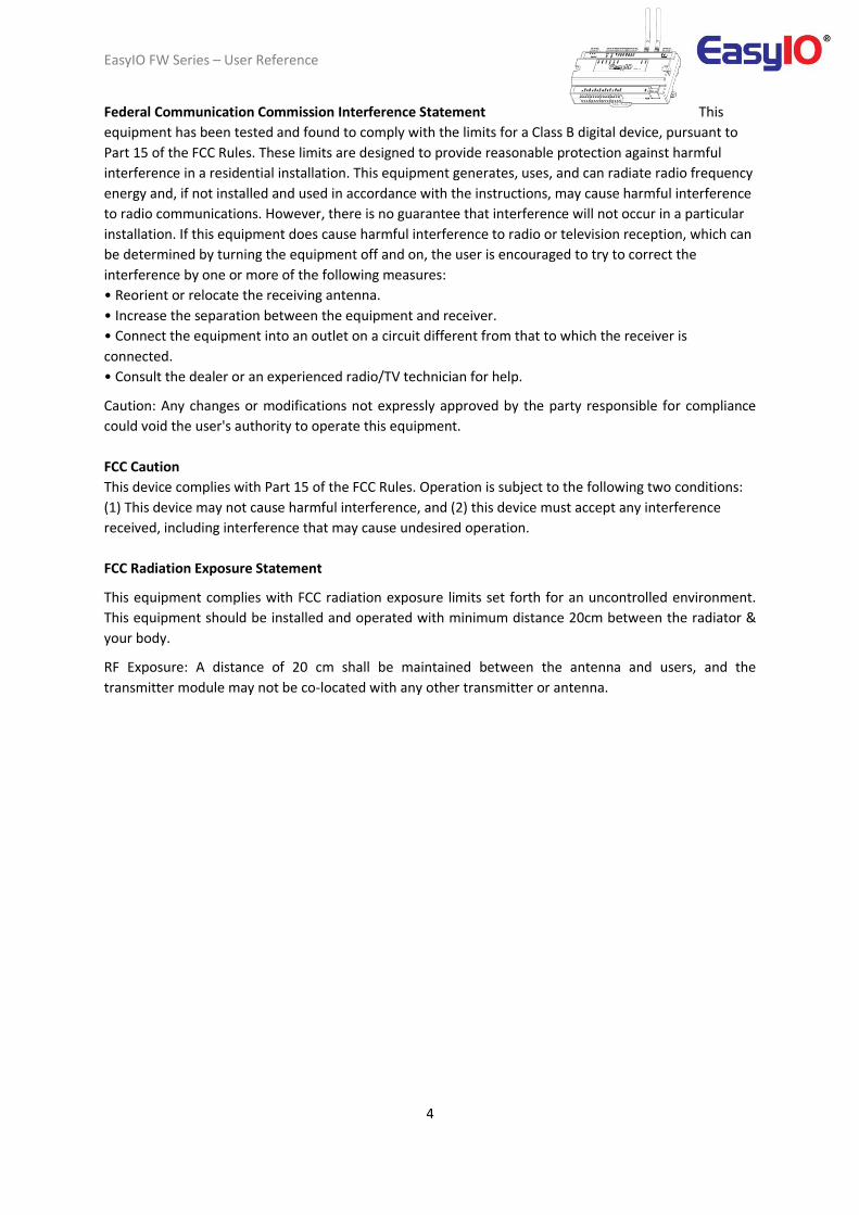
FCC Radiation Exposure Statement
This equipment complies with FCC radiation exposure limits set forth for an uncontrolled environment.
This equipment should be installed and operated with minimum distance 20cm between the radiator &
your body.
RF Exposure: A distance of 20 cm shall be maintained between the antenna and users, and the
transmitter module may not be co-located with any other transmitter or antenna.
EasyIO FW Series – User Reference
5
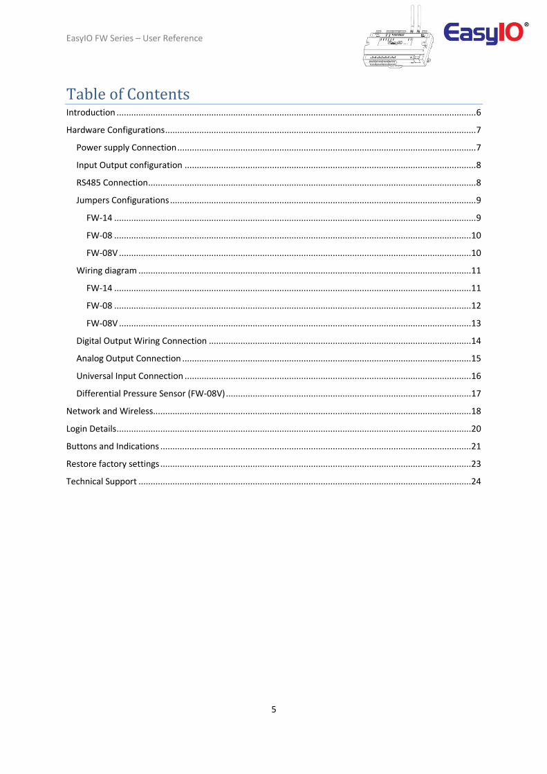
Table of Contents Introduction .................................................................................................................................................... 6
Hardware Configurations ................................................................................................................................ 7
Power supply Connection ........................................................................................................................... 7
Input Output configuration ........................................................................................................................ 8
RS485 Connection ....................................................................................................................................... 8
Jumpers Configurations .............................................................................................................................. 9
FW-14 ..................................................................................................................................................... 9
FW-08 ................................................................................................................................................... 10
FW-08V ................................................................................................................................................. 10
Wiring diagram ......................................................................................................................................... 11
FW-14 ................................................................................................................................................... 11
FW-08 ................................................................................................................................................... 12
FW-08V ................................................................................................................................................. 13
Digital Output Wiring Connection ............................................................................................................ 14
Analog Output Connection ....................................................................................................................... 15
Universal Input Connection ...................................................................................................................... 16
Differential Pressure Sensor (FW-08V) ..................................................................................................... 17
Network and Wireless................................................................................................................................... 18
Login Details .................................................................................................................................................. 20
Buttons and Indications ................................................................................................................................ 21
Restore factory settings ................................................................................................................................ 23
Technical Support ......................................................................................................................................... 24
EasyIO FW Series – User Reference
6
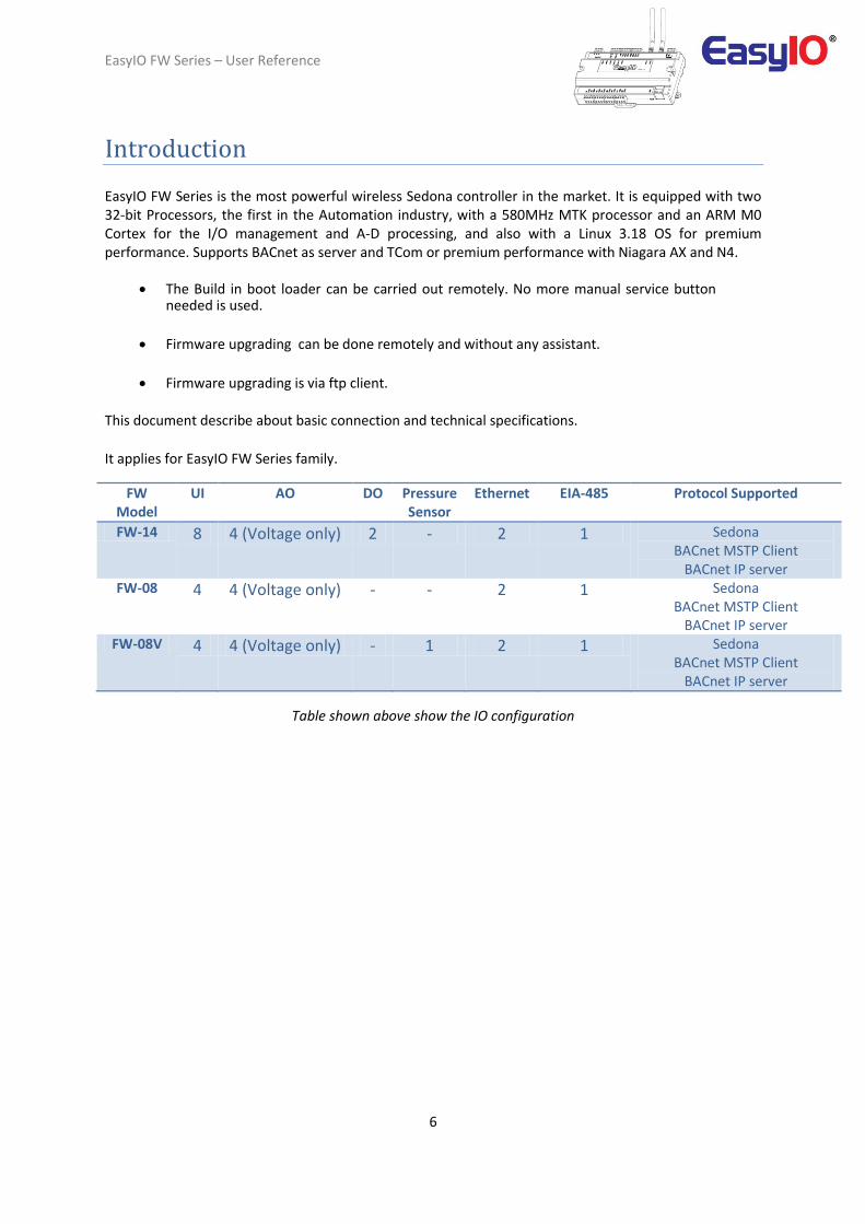
Introduction EasyIO FW Series is the most powerful wireless Sedona controller in the market. It is equipped with two 32-bit Processors, the first in the Automation industry, with a 580MHz MTK processor and an ARM M0 Cortex for the I/O management and A-D processing, and also with a Linux 3.18 OS for premium performance. Supports BACnet as server and TCom or premium performance with Niagara AX and N4.
The Build in boot loader can be carried out remotely. No more manual service button needed is used.
Firmware upgrading can be done remotely and without any assistant.
Firmware upgrading is via ftp client. This document describe about basic connection and technical specifications.
It applies for EasyIO FW Series family.
FW Model
UI AO DO Pressure Sensor
Ethernet EIA-485 Protocol Supported
FW-14 8 4 (Voltage only) 2 - 2 1 Sedona BACnet MSTP Client
BACnet IP server FW-08 4 4 (Voltage only) - - 2 1 Sedona
BACnet MSTP Client BACnet IP server
FW-08V 4 4 (Voltage only) - 1 2 1 Sedona BACnet MSTP Client
BACnet IP server
Table shown above show the IO configuration

EasyIO FW Series – User Reference
7
Hardware Configurations
Power supply Connection Both AC and DC can be used for EasyIO FW Series controller. Refer to electrical specification for the working range. In order to avoid damage on the controller input/output devices and RS485 connection, use individual power supply for each controller. If a single power supply is used to power up multiple EasyIO FW series, make sure controller power supplies are connected with the same polarity.
Electrical Power Supply 24V AC +/- 5% or 24V DC +20%/-15%
Consumption 500 mA
Operating Temperature 32 to 150 Deg-F (0 to 65 Deg-C)
Storage Temperature -4 to 150 Deg-F (-20 to 65 Deg-C)
Operating Humidity 10% to 70% relative humidity non-condensing
Power Supply Connection
Multiple controllers share single transformer connection

EasyIO FW Series – User Reference
8
Input Output configuration FW Series range of products comes in few options. Options are referring to IO (Input/Output) configurations.
FW Model
UI AO DO Pressure Sensor
Ethernet EIA-485 Protocol Supported
FW-14 8 4 (Voltage only) 2 0 2 1 Sedona BACnet MSTP Client
BACnet IP server FW-08 4 4 (Voltage only) 0 0 2 1 Sedona
BACnet MSTP Client BACnet IP server
FW-08V 4 4 (Voltage only) 0 1 2 1 Sedona BACnet MSTP Client
BACnet IP server
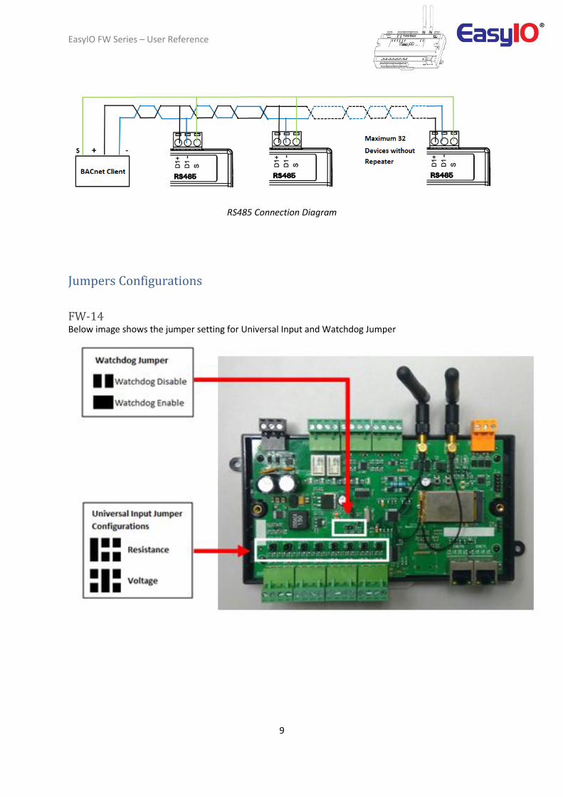
RS485 Connection RS485 connection must be terminated at both ends with termination resistor, typically 120 Ohms. It is recommended to use shielded twisted pair wire (STP) for the wiring.
Lightning protection circuit is highly recommended to be installed at one end of the wiring. The controller should be wired in daisy chain network topology as shown as image below. If wire branch can be avoided, keep it as short as possible, and never connect more than one device to the wire branch (it is not recommended).
Be careful if single power supply is used for all connected RS485 device, make sure all devices are having the same ground connection. Make sure you are connecting the same wire for the same terminal position, all “H” terminals connected to the same wire.
Physical Interface
Remark
EIA-485
BUS A,B Two Wire, Half Duplex Speed:(9.6K, 19.2k, 38.4K),
Data Bit:(8 bits),
Parity:(None)
Ethernet 10/100 Mbps IP, TCP, UDP, ICMP, HTTP,FTP
Application Support Sedona, BACnet MSTP Client, BACnet IP Server and Tcom
Daisy Chain Network Topology
EasyIO FW Series – User Reference
9
RS485 Connection Diagram
Jumpers Configurations
FW-14 Below image shows the jumper setting for Universal Input and Watchdog Jumper

EasyIO FW Series – User Reference
10
FW-08 Below image shows the jumper setting for Universal Input and Watchdog Jumper
FW-08V Below image shows the jumper setting for Universal Input and Watchdog Jumper

EasyIO FW Series – User Reference
11
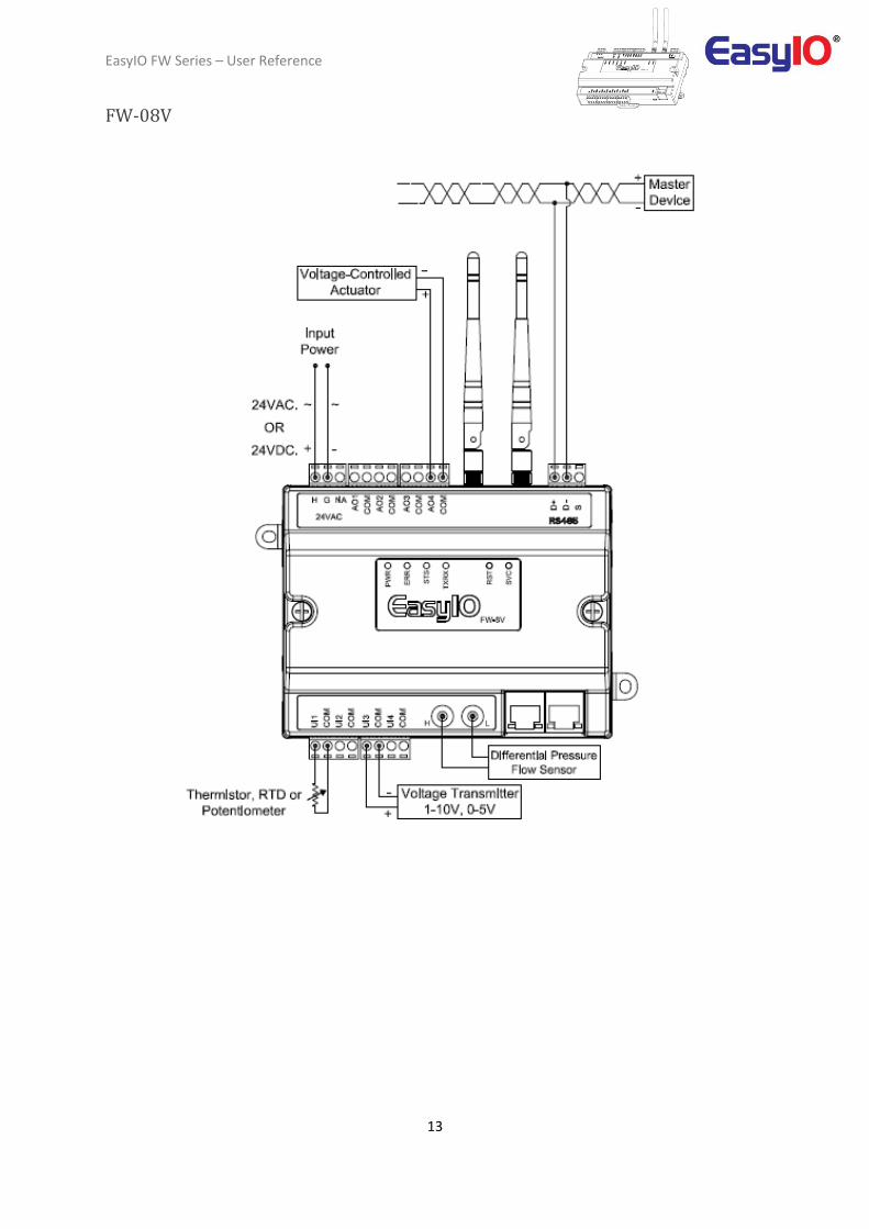
Wiring diagram Below diagram shows the general wiring diagram for FW series according to its model.
FW-14

EasyIO FW Series – User Reference
12
FW-08
EasyIO FW Series – User Reference
13
FW-08V
EasyIO FW Series – User Reference
14
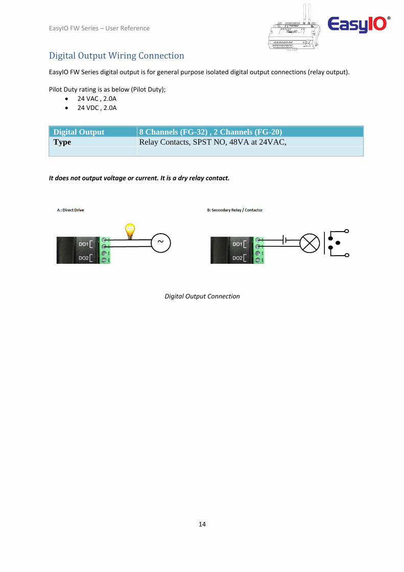
Digital Output Wiring Connection EasyIO FW Series digital output is for general purpose isolated digital output connections (relay output). Pilot Duty rating is as below (Pilot Duty);
24 VAC , 2.0A
24 VDC , 2.0A
Digital Output 8 Channels (FG-32) , 2 Channels (FG-20)
Type Relay Contacts, SPST NO, 48VA at 24VAC,
It does not output voltage or current. It is a dry relay contact.
Digital Output Connection

EasyIO FW Series – User Reference
15
Analog Output Connection EasyIO FW series has Analog Output connections. Each Analog Output can only drive voltage. The working range for voltage is 0 – 10V.
Universal Output
4 Channels
Type Voltage: 0 – 10VDC , Min Impedance 10K Ohm.

EasyIO FW Series – User Reference
16
Universal Input Connection EasyIO FW series has non-isolated universal inputs. The universal input supports three type of analog signal i.e. resistance and voltage via hardware jumper and internal register settings:
Universal Input 8 Channels
Voltage 0 - 10V DC (+/-0.05V)
Resistance 500 - 500K (+/-10 Ohm)
Thermistor 10K, 20K, 1K Balco, 1K Platinum : All (+/-0.1 Deg-C)
UI as Digital Input Voltage Free Contact
a) Resistance – The working range of resistance is 500 Ohm – 500k Ohm.
The commonly used Thermistor such as 10K, 20K, 1K Balco and 1K Platinum are all supported.
b) Voltage – Supports 0 – 10V and 0 – 5V (scaling required).
The minimum input impedance of voltage mode input is 1 Mega Ohm.
EasyIO FW Series – User Reference
17
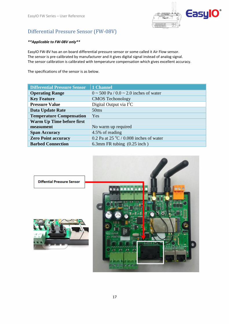
Differential Pressure Sensor (FW-08V) **Applicable to FW-08V only** EasyIO FW-8V has an on board differential pressure sensor or some called it Air Flow sensor. The sensor is pre-calibrated by manufacturer and it gives digital signal instead of analog signal. The sensor calibration is calibrated with temperature compensation which gives excellent accuracy. The specifications of the sensor is as below.
Differential Pressure Sensor 1 Channel
Operating Range 0 ~ 500 Pa / 0.0 ~ 2.0 inches of water
Key Feature CMOS Techonology
Pressure Value Digital Output via I2C
Data Update Rate 50ms
Temperature Compensation Yes
Warm Up Time before first
measument No warm up required
Span Accuracy 4.5% of reading
Zero Point accuracy 0.2 Pa at 25 oC / 0.008 inches of water
Barbed Connection 6.3mm FR tubing (0.25 inch )

EasyIO FW Series – User Reference
18
Network and Wireless EasyIO FW series comes with on board wireless connection and 2 ethernet ports. The wireless network comply to IEEE 802.11 standards. It supports IEEE 802.11 B/G/N standard. Each unit is supplied with two (2) 2dBi RP-SMA female jack antenna. FW Series Wi-Fi Access Point name is preset at factory. Each unit has 2 Wi-Fi Access Point as below. SSID 1 : FW-xxxx , where xxxx is the last 4 digit of the MAC address 01. SSID 2 : Conf-xxxx , where xxx is the last 4 digit of the MAC address 01 (Hidden by default) Mac Address label located at the bottom casing top right hand corner of each FW series controller. Password for both SSID is 12345678. ** Please change the password to secure the connection**
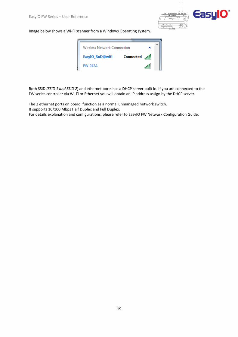
In the example above, the MAC address 1 is 38:D1:35:02:01:2A, you should to scan the SSID as FW-012A from any Wi-Fi Scanner.
EasyIO FW Series – User Reference
19
Image below shows a Wi-Fi scanner from a Windows Operating system.
Both SSID (SSID 1 and SSID 2) and ethernet ports has a DHCP server built in. If you are connected to the FW series controller via Wi-Fi or Ethernet you will obtain an IP address assign by the DHCP server. The 2 ethernet ports on board function as a normal unmanaged network switch. It supports 10/100 Mbps Half Duplex and Full Duplex. For details explanation and configurations, please refer to EasyIO FW Network Configuration Guide.
EasyIO FW Series – User Reference
20
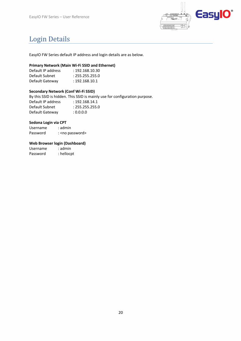
Login Details
EasyIO FW Series default IP address and login details are as below.
Primary Network (Main Wi-Fi SSID and Ethernet) Default IP address : 192.168.10.30 Default Subnet : 255.255.255.0 Default Gateway : 192.168.10.1 Secondary Network (Conf Wi-Fi SSID) By this SSID is hidden. This SSID is mainly use for configuration purpose. Default IP address : 192.168.14.1 Default Subnet : 255.255.255.0 Default Gateway : 0.0.0.0 Sedona Login via CPT Username : admin Password : <no password> Web Browser login (Dashboard) Username : admin Password : hellocpt

EasyIO FW Series – User Reference
21
Buttons and Indications
The controller will do a hardware reset when the Reset Button is pressed whenever manual restart is required. The Service button is used to activate the built-in boot loader program for software upgrade. Each digital output has a correspondence LED to indicate its current state.
Image shows the Reset button, Service button and also TXRX indicators.
Image shown is an EasyIO FW-14 unit.
Image shows the Status indicator, Error indicator and individual Digital Output indicator

EasyIO FW Series – User Reference
22
Button and LED indications. Image shown is an EasyIO FW-14.
LED Conditions
Description
Pattern: continuously blinking. ERR is to indicate whenever there is
1 ERR
Communication errors. Pattern: constantly light up. The controller is undergoing firmware upgrading. This is normal during firmware upgrade process.
STS is used to indicate the heartbeat of the
2 STS Microcontroller. The STS LED will blink at
1-second interval in normal operation
Condition.
TXRX is used to indicate when there are
3 TX/RX Communication activities in Port 1.
(Transmitting or Receiving) on the
Communication port.

EasyIO FW Series – User Reference
23
Restore factory settings
This function is done with just the by pressing the “Service” button while the controller is booting up. A restore to factory settings will do the following;
1. Restore the IP address to the default which is 192.168.10.30 2. Clear the Sedona application in the Sedona VM back to default (default app is an empty app) 3. A default Sedona apps default login is admin, <no password>.
Follow the steps below to restore to factory settings.
Step 1 Make sure you backup the Sedona apps if you have connection to the EasyIO FW-14. Step 2 Cycle power and within 5 seconds press and HOLD down the service button until the Error LED starts to flash. This process will take approximately 45 seconds before the error Led start to blink. Just keep holding down the service button till the RED led start to flash. Step 3 Once the Red LED flashes, you can release the service button. Then a momentary press the service button will restore back the FW-14 controller back to factory default state.

EasyIO FW Series – User Reference
24
Technical Support
For technical issue, please contact Email :[email protected]
Related Documents


![FW: [Fwd: FW: Beautiful_TIBET]](https://static.cupdf.com/doc/110x72/54b8dcf94a79592d6a8b4612/fw-fwd-fw-beautifultibet.jpg)