Introduction This document attempts to record the early development of shunt diode safety barriers within the United Kingdom.[1961-1971], with a brief reference to the subsequent expansion. It demonstrates that to succeed it was necessary for many people from different sections of the process instrument industry, to recognise the need for barriers and to become involved in the development and acceptance process. The significant contribution of many of these people is generally not recognised. During this period the author was employed at Kent Instruments Ltd in the Research Department, which at that time allowed individuals the freedom to explore their particular individual interests. Support for the barrier project was limited to a few individuals and it was opposed by an even smaller [but influential] number. The majority of the people who might have been expected to have an interest in the technique because of the possible effect on process instrumentation were totally indifferent. Inevitably some people who made significant contributions will have been omitted from this account or possibly had their names miss-spelled and profuse apologies are offered in anticipation of this error. Any account of the past is always influenced by the author’s recollections and prejudices. If these are too evident in this particular case a further apology is offered. Developments in the field of intrinsic safety always take a long time. The development of the initial concept and the need to consult others who are involved in certification or the application of instruments and can bring a different viewpoint are factors which contribute to the time taken. The tortuous path through the certification labyrinth, which usually includes the creation of new standards or the modification of existing standards and the creation of an acceptable Code of Practice also contribute to the elapsed time. All these factors are illustrated by this document. This long time scale and the indeterminate costs involved serve as a deterrent to the majority of financially controlled manufacturers entering this field but the long term rewards can be significant. Shunt diode safety barriers are still manufactured in significant numbers and several million have been manufactured and installed since the concept was introduced. The following history is based on some recollections but reinforced by the information listed in the appendix which is supported by existing documentation. This document only discusses the development within the UK. Parallel development in other countries did take place towards the end of this period particularly in Germany but detailed accurate information of this development is not readily available to the author and hence is not included. History The concept years 1961-1963 It is recognised that the 1960’s were very different from the current situation. Then BS 1259 was the current standard for intrinsic safety, and CENELEC and IEC standards did not exist. The current equivalent of BS 1259 [18 A5 pages] is a combination of the general requirements BS EN 60079-0 [88pages],apparatus standard BS EN 60079-11[141pages] and the system standard BS EN 60079-25 [74 pages]. The grand total of 303 A4 pages as compared with 18 A5 pages represents the advance in technology or the submerging in bureaucracy depending on your viewpoint. Probably it is a little of both. At this time, certification of intrinsically safe equipment for surface industries in the UK was the responsibility of the Factory Inspectorate, based on testing by the Safety-in-Mines Research Establishment [SMRE] in Sheffield. In 1961 intrinsic safety as a technique for instrumentation in surface industry in the UK was beginning to be an acceptable technique in the petrochemical and pharmaceutical industries but was not widely accepted in refineries. Germany was further advanced in accepting the technique and the USA was firmly wedded to the plumbing of the explosion proof technique. For new developments in this field the current situation on first appraisal appears to be very different but the circumstances Early history of shunt diode safety barriers Synopsis The history of the development of shunt diode safety barriers in the United Kingdom from 1961-1971 is used to illustrate the time taken and the many factors affecting the development of light current equipment for use in hazardous areas. Chris Towle

Welcome message from author
This document is posted to help you gain knowledge. Please leave a comment to let me know what you think about it! Share it to your friends and learn new things together.
Transcript
Introduction
This document attempts to record the early development of shunt diode safety barriers within the United Kingdom.[1961-1971], with a brief reference to the subsequent expansion. It demonstrates that to succeed it was necessary for many people from different sections of the process instrument industry, to recognise the need for barriers and to become involved in the development and acceptance process. The significant contribution of many of these people is generally not recognised. During this period the author was employed at Kent Instruments Ltd in the Research Department, which at that time allowed individuals the freedom to explore their particular individual interests. Support for the barrier project was limited to a few individuals and it was opposed by an even smaller [but influential] number. The majority of the people who might have been expected to have an interest in the technique because of the possible effect on process instrumentation were totally indifferent. Inevitably some people who made significant contributions will have been omitted from this account or possibly had their names miss-spelled and profuse apologies are offered in anticipation of this error. Any account of the past is always influenced by the author’s recollections and prejudices. If these are too evident in this particular case a further apology is offered.
Developments in the field of intrinsic safety always take a long time. The development of the initial concept and the need to consult others who are involved in certification or the application of instruments and can bring a different viewpoint are factors which contribute to the time taken. The tortuous path through the certification labyrinth, which usually includes the creation of new standards or the modification of existing standards and the creation of an acceptable Code of Practice also contribute to the elapsed time. All these factors are illustrated by this document. This long time scale and the indeterminate costs involved serve as a deterrent to the majority of financially controlled manufacturers entering this field but the long term rewards can be significant. Shunt diode safety barriers are still manufactured in significant numbers and several million have been manufactured and installed since the concept was introduced. The following history is based on some recollections but reinforced by the information listed in the appendix which is supported by existing documentation. This document only discusses the development within the UK. Parallel development in other countries did take place towards the end of this period particularly in Germany but detailed accurate information of this development is not readily available to the author and hence is not included.
History
The concept years 1961-1963It is recognised that the 1960’s were very different from the current situation. Then BS 1259 was the current standard for intrinsic safety, and CENELEC and IEC standards did not exist. The current equivalent of BS 1259 [18 A5 pages] is a combination of the general requirements BS EN 60079-0 [88pages],apparatus standard BS EN 60079-11[141pages] and the system standard BS EN 60079-25 [74 pages]. The grand total of 303 A4 pages as compared with 18 A5 pages represents the advance in technology or the submerging in bureaucracy depending on your viewpoint. Probably it is a little of both. At this time, certification of intrinsically safe equipment for surface industries in the UK was the responsibility of the Factory Inspectorate, based on testing by the Safety-in-Mines Research Establishment [SMRE] in Sheffield. In 1961 intrinsic safety as a technique for instrumentation in surface industry in the UK was beginning to be an acceptable technique in the petrochemical and pharmaceutical industries but was not widely accepted in refineries. Germany was further advanced in accepting the technique and the USA was firmly wedded to the plumbing of the explosion proof technique. For new developments in this field the current situation on first appraisal appears to be very different but the circumstances
Early history of shunt diode safety barriers
Synopsis
The history of the development of shunt diode safety barriers in the United Kingdom from 1961-1971 is used to illustrate the time taken and the many factors affecting the development of light current equipment for use in hazardous areas.
Chris Towle
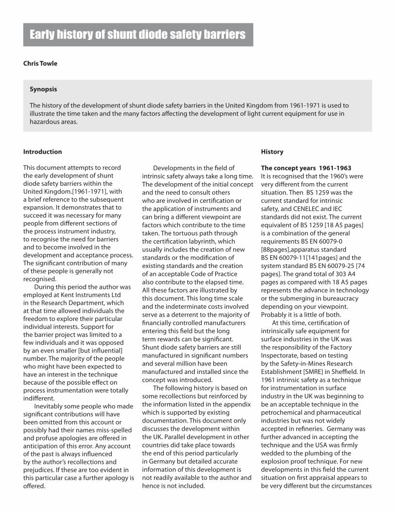
are fundamentally similar and new developments still take a similar time as illustrated by the FISCO [Fieldbus] and Power ’i’ developments. The first use of zener diodes for the limitation of voltage in intrinsically safe circuits in the UK was probably in the output isolator stage of a very early [1959] electronic controller manufactured by Evershed and Vignoles. The possible use of a fuse/ zener diode/resistor network as a barrier was first publicly discussed by Bob Redding at a symposium [organised by Ludwig Finklestein]at Northampton College of Advanced Technology [now City University]
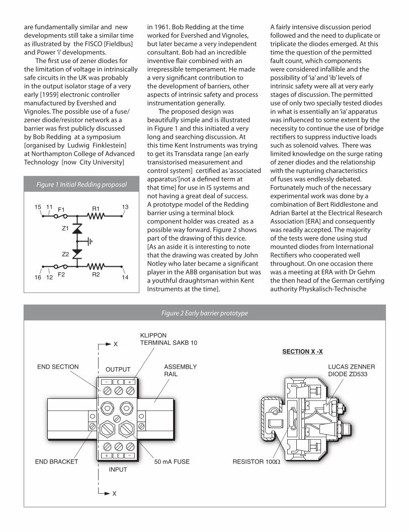
in 1961. Bob Redding at the time worked for Evershed and Vignoles, but later became a very independent consultant. Bob had an incredible inventive flair combined with an irrepressible temperament. He made a very significant contribution to the development of barriers, other aspects of intrinsic safety and process instrumentation generally. The proposed design was beautifully simple and is illustrated in Figure 1 and this initiated a very long and searching discussion. At this time Kent Instruments was trying to get its Transdata range [an early transistorised measurement and control system] certified as ‘associated apparatus’[not a defined term at that time] for use in IS systems and not having a great deal of success. A prototype model of the Redding barrier using a terminal block component holder was created as a possible way forward. Figure 2 shows part of the drawing of this device. [As an aside it is interesting to note that the drawing was created by John Notley who later became a significant player in the ABB organisation but was a youthful draughtsman within Kent Instruments at the time].
A fairly intensive discussion period followed and the need to duplicate or triplicate the diodes emerged. At this time the question of the permitted fault count, which components were considered infallible and the possibility of ‘ia’ and ‘ib’ levels of intrinsic safety were all at very early stages of discussion. The permitted use of only two specially tested diodes in what is essentially an ‘ia’ apparatus was influenced to some extent by the necessity to continue the use of bridge rectifiers to suppress inductive loads such as solenoid valves. There was limited knowledge on the surge rating of zener diodes and the relationship with the rupturing characteristics of fuses was endlessly debated. Fortunately much of the necessary experimental work was done by a combination of Bert Riddlestone and Adrian Bartel at the Electrical Research Association [ERA] and consequently was readily accepted. The majority of the tests were done using stud mounted diodes from International Rectifiers who cooperated well throughout. On one occasion there was a meeting at ERA with Dr Gehm the then head of the German certifying authority Physkalisch-Technische
_E+
_ E +
X
X
ASSEMBLYRAIL
50 mA FUSE
END SECTION OUTPUT
SECTION X -X
INPUTEND BRACKET
LUCAS ZENNERDIODE ZD533
KLIPPONTERMINAL SAKB 10
RESISTOR 100Ω
Figure 1 Initial Redding proposal
Figure 2 Early barrier prototype
11 F1
Z1
Z2
R1 1315
12 F2 R2 1416
Bundesanstalt [PTB] who was not in favour of barriers and had recorded the statement that ‘ barriers would never be permitted in Germany’. This reflected a Germanic preference for isolation which is still present and was possibly influenced by their skills with magnetic amplifiers. [Hartman Braun used them very successfully in the 1960’s] This was a considerable setback at the time because even then the European market was significant from both economic and technical acceptance reasons. Later this attitude softened slightly and a PTB document in 1969 discussed the application of barriers but only allowed their application in Zone1 with well-defined earthing requirements.
Early prototypes and further evaluation 1963-1964
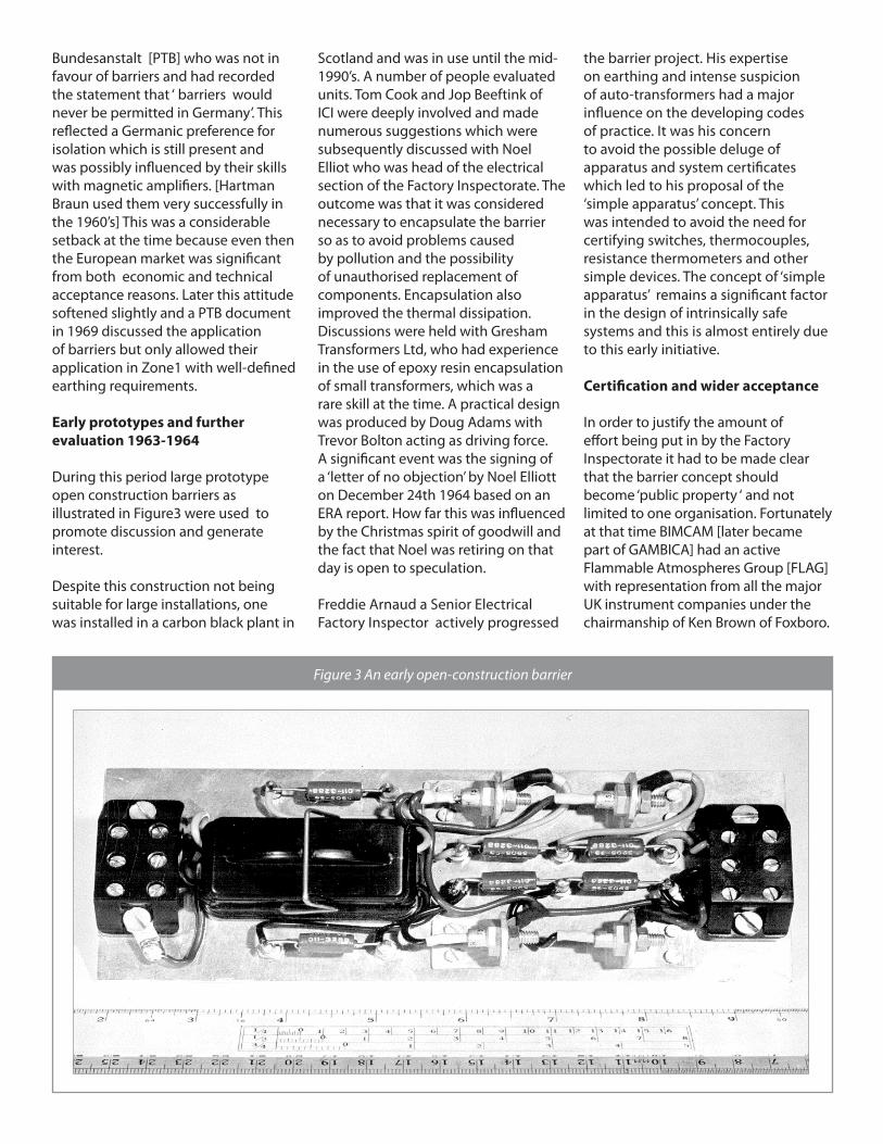
During this period large prototype open construction barriers as illustrated in Figure3 were used to promote discussion and generate interest.
Despite this construction not being suitable for large installations, one was installed in a carbon black plant in
Scotland and was in use until the mid-1990’s. A number of people evaluated units. Tom Cook and Jop Beeftink of ICI were deeply involved and made numerous suggestions which were subsequently discussed with Noel Elliot who was head of the electrical section of the Factory Inspectorate. The outcome was that it was considered necessary to encapsulate the barrier so as to avoid problems caused by pollution and the possibility of unauthorised replacement of components. Encapsulation also improved the thermal dissipation. Discussions were held with Gresham Transformers Ltd, who had experience in the use of epoxy resin encapsulation of small transformers, which was a rare skill at the time. A practical design was produced by Doug Adams with Trevor Bolton acting as driving force. A significant event was the signing of a ‘letter of no objection’ by Noel Elliott on December 24th 1964 based on an ERA report. How far this was influenced by the Christmas spirit of goodwill and the fact that Noel was retiring on that day is open to speculation.
Freddie Arnaud a Senior Electrical Factory Inspector actively progressed
the barrier project. His expertise on earthing and intense suspicion of auto-transformers had a major influence on the developing codes of practice. It was his concern to avoid the possible deluge of apparatus and system certificates which led to his proposal of the ‘simple apparatus’ concept. This was intended to avoid the need for certifying switches, thermocouples, resistance thermometers and other simple devices. The concept of ‘simple apparatus’ remains a significant factor in the design of intrinsically safe systems and this is almost entirely due to this early initiative.
Certification and wider acceptance
In order to justify the amount of effort being put in by the Factory Inspectorate it had to be made clear that the barrier concept should become ‘public property ‘ and not limited to one organisation. Fortunately at that time BIMCAM [later became part of GAMBICA] had an active Flammable Atmospheres Group [FLAG] with representation from all the major UK instrument companies under the chairmanship of Ken Brown of Foxboro.
Figure 3 An early open-construction barrier
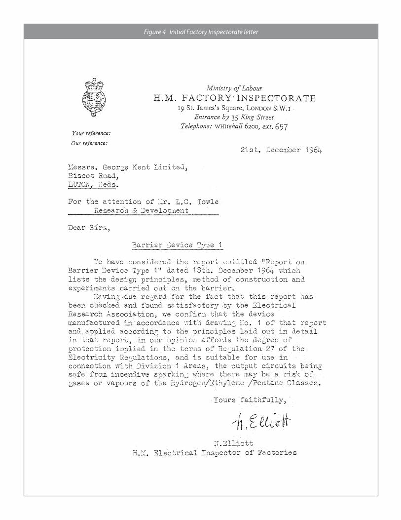
Figure 4 Initial Factory Inspectorate letter
NOTE: BIMCAM was The British Industrial Measuring & Control Apparatus Manufacturers’ Association. The initials GAMBICA do not translate into a name which adequately covers the combination of instrumentation orientated organisations which form its membership; hence these letters are just a name.
At that time Foxboro, Taylor, Honeywell, Kent and General Electric were all members of FLAG and lunch at the St Ermin’s hotel, Westminster was a considerable attraction. FLAG plus Bob Redding became the core of the co-operative action on barriers. Possibly the group’s most useful action was the publication of the BIMCAM code of practice on barriers which served industry well for a number of years before being replaced by the BASEEFA code of practice SFA 3004. The publication of this document was due to the persistence of Ken Brown who overcame the initial resistance of the BIMCAM council. The relationship between the various participants was stretched at times but problems were usually resolved because in general the problems did not involve what was perceived as high commercial stakes and the participants were engineers. A typical problem was that barriers had to carry a manufacture’s name because of the certification requirements. The 28V 240Ω barrier was developed by a combination of Kent and Taylor activity. Ron Sunderland and Olec Binski of Taylor Instruments Ltd were deeply involved and the question of whose name should be used inevitably arose. The problem disappeared when a senior director at Kents refused to pay the certification fee [a few hundred pounds] and Taylor with a better sense for future potential willingly stepped in. In the late 1960’s the co-
operation weakened, and Foxboro, Honeywell and Taylor all introduced variants on the theme, but the major usage remained with the Kent/Taylor versions. At about this time other UK manufacturers , notably Robertson and Davy United developed barriers for specific applications. During the period from 1964 to 1967, the early discussions were mostly with ‘Widge’ Widginton [testing being done by ’Bish ‘ Bishop ] with inputs from other members of SMRE and ERA and all other relevant and some irrelevant organisations. Topics included were, whether to use the UK cadmium curves or the PTB version, the characteristics of fuses compared to the surge rating of diodes and the reliability of earth connections. The use of cable parameters and other aspects of system design were all under discussion at this time and contributed to the general confusion. The possibility of applying and certifying barriers initiated many of the questions relating to intrinsically safe system design and this made a major contribution to the subsequent development of the ‘entity concept’ and system standard. The British Approvals Service for Electrical Equipment[BASEEFA]
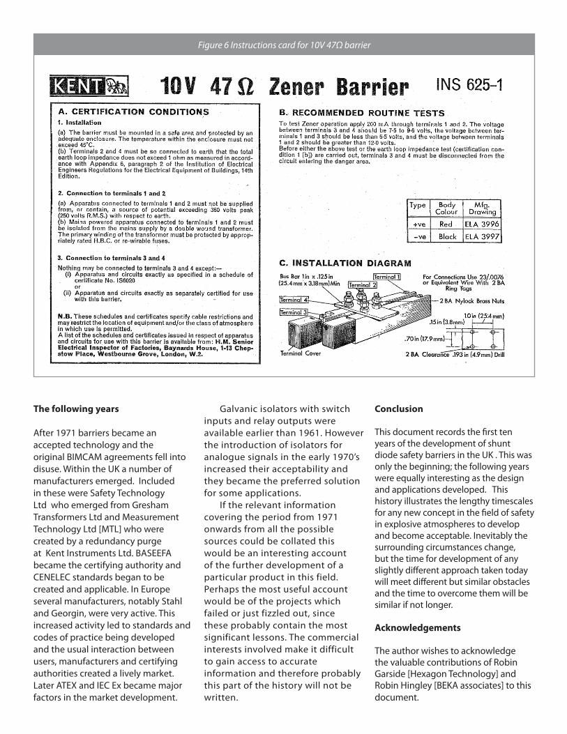
was created in 1967. Many of the SMRE staff transferred to BASEEFA and continued to deal with barrier certification and consequently the changeover had little effect on the progress of certification. However BASEEFA was, and in its modified form still is, a major influence in the development of barriers and intrinsic safety as a whole. The Factory Inspectorate certificates emerged in 1967-8. A comprehensive test report on the 10V 47Ω barrier was compiled in March 1967 [signed by J.Cartwright].The certificate followed in August and stipulated the use of the instructions card illustrated in Figure 6.
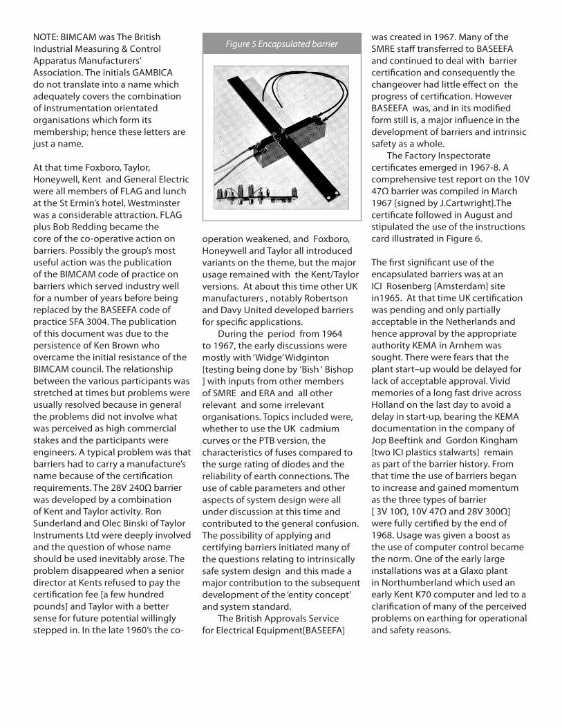
The first significant use of the encapsulated barriers was at an ICI Rosenberg [Amsterdam] site in1965. At that time UK certification was pending and only partially acceptable in the Netherlands and hence approval by the appropriate authority KEMA in Arnhem was sought. There were fears that the plant start–up would be delayed for lack of acceptable approval. Vivid memories of a long fast drive across Holland on the last day to avoid a delay in start-up, bearing the KEMA documentation in the company of Jop Beeftink and Gordon Kingham [two ICI plastics stalwarts] remain as part of the barrier history. From that time the use of barriers began to increase and gained momentum as the three types of barrier [ 3V 10Ω, 10V 47Ω and 28V 300Ω] were fully certified by the end of 1968. Usage was given a boost as the use of computer control became the norm. One of the early large installations was at a Glaxo plant in Northumberland which used an early Kent K70 computer and led to a clarification of many of the perceived problems on earthing for operational and safety reasons.
Figure 5 Encapsulated barrier
The following years
After 1971 barriers became an accepted technology and the original BIMCAM agreements fell into disuse. Within the UK a number of manufacturers emerged. Included in these were Safety Technology Ltd who emerged from Gresham Transformers Ltd and Measurement Technology Ltd [MTL] who were created by a redundancy purge at Kent Instruments Ltd. BASEEFA became the certifying authority and CENELEC standards began to be created and applicable. In Europe several manufacturers, notably Stahl and Georgin, were very active. This increased activity led to standards and codes of practice being developed and the usual interaction between users, manufacturers and certifying authorities created a lively market. Later ATEX and IEC Ex became major factors in the market development.
Galvanic isolators with switch inputs and relay outputs were available earlier than 1961. However the introduction of isolators for analogue signals in the early 1970’s increased their acceptability and they became the preferred solution for some applications. If the relevant information covering the period from 1971 onwards from all the possible sources could be collated this would be an interesting account of the further development of a particular product in this field. Perhaps the most useful account would be of the projects which failed or just fizzled out, since these probably contain the most significant lessons. The commercial interests involved make it difficult to gain access to accurate information and therefore probably this part of the history will not be written.
Conclusion
This document records the first ten years of the development of shunt diode safety barriers in the UK . This was only the beginning; the following years were equally interesting as the design and applications developed. This history illustrates the lengthy timescales for any new concept in the field of safety in explosive atmospheres to develop and become acceptable. Inevitably the surrounding circumstances change, but the time for development of any slightly different approach taken today will meet different but similar obstacles and the time to overcome them will be similar if not longer.
Acknowledgements
The author wishes to acknowledge the valuable contributions of Robin Garside [Hexagon Technology] and Robin Hingley [BEKA associates] to this document.
Figure 6 Instructions card for 10V 47Ω barrier
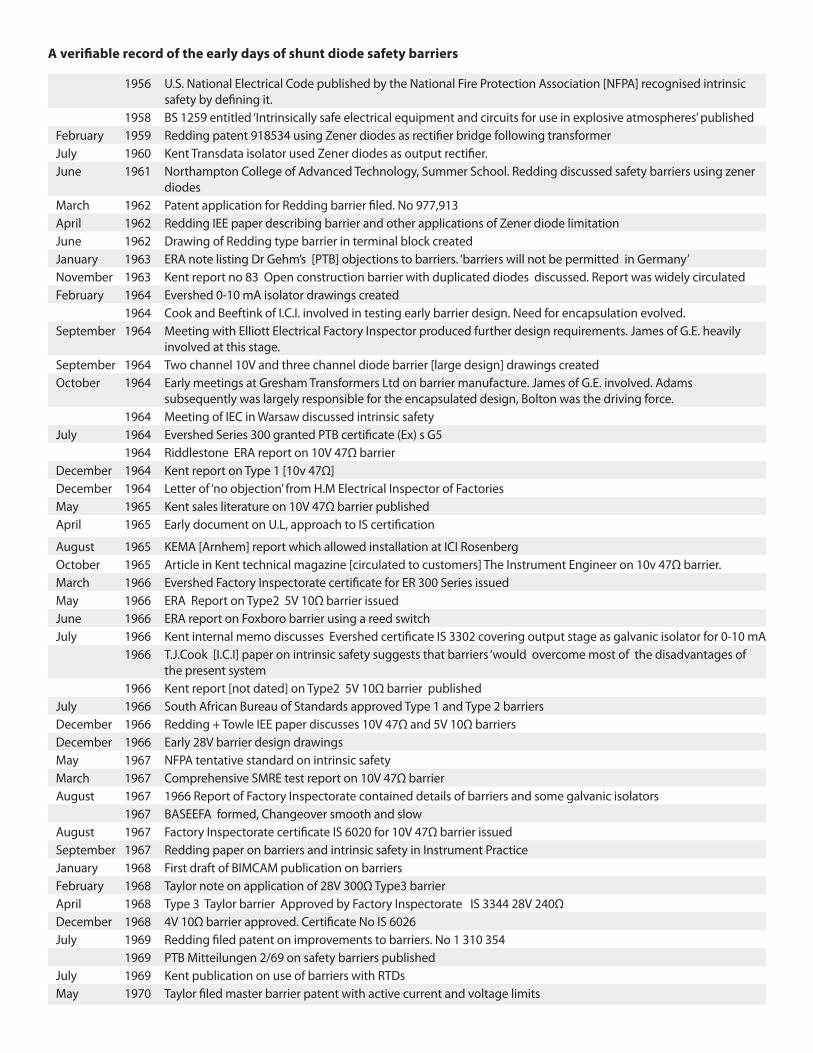
A verifiable record of the early days of shunt diode safety barriers
1956 U.S. National Electrical Code published by the National Fire Protection Association [NFPA] recognised intrinsic safety by defining it.
1958 BS 1259 entitled ‘Intrinsically safe electrical equipment and circuits for use in explosive atmospheres’ publishedFebruary 1959 Redding patent 918534 using Zener diodes as rectifier bridge following transformerJuly 1960 Kent Transdata isolator used Zener diodes as output rectifier.June 1961 Northampton College of Advanced Technology, Summer School. Redding discussed safety barriers using zener
diodesMarch 1962 Patent application for Redding barrier filed. No 977,913April 1962 Redding IEE paper describing barrier and other applications of Zener diode limitationJune 1962 Drawing of Redding type barrier in terminal block createdJanuary 1963 ERA note listing Dr Gehm’s [PTB] objections to barriers. ‘barriers will not be permitted in Germany’November 1963 Kent report no 83 Open construction barrier with duplicated diodes discussed. Report was widely circulatedFebruary 1964 Evershed 0-10 mA isolator drawings created
1964 Cook and Beeftink of I.C.I. involved in testing early barrier design. Need for encapsulation evolved.September 1964 Meeting with Elliott Electrical Factory Inspector produced further design requirements. James of G.E. heavily
involved at this stage.September 1964 Two channel 10V and three channel diode barrier [large design] drawings createdOctober 1964 Early meetings at Gresham Transformers Ltd on barrier manufacture. James of G.E. involved. Adams
subsequently was largely responsible for the encapsulated design, Bolton was the driving force.1964 Meeting of IEC in Warsaw discussed intrinsic safety
July 1964 Evershed Series 300 granted PTB certificate (Ex) s G51964 Riddlestone ERA report on 10V 47Ω barrier
December 1964 Kent report on Type 1 [10v 47Ω]December 1964 Letter of ‘no objection’ from H.M Electrical Inspector of FactoriesMay 1965 Kent sales literature on 10V 47Ω barrier publishedApril 1965 Early document on U.L, approach to IS certification
August 1965 KEMA [Arnhem] report which allowed installation at ICI RosenbergOctober 1965 Article in Kent technical magazine [circulated to customers] The Instrument Engineer on 10v 47Ω barrier.March 1966 Evershed Factory Inspectorate certificate for ER 300 Series issuedMay 1966 ERA Report on Type2 5V 10Ω barrier issuedJune 1966 ERA report on Foxboro barrier using a reed switchJuly 1966 Kent internal memo discusses Evershed certificate IS 3302 covering output stage as galvanic isolator for 0-10 mA
1966 T.J.Cook [I.C.I] paper on intrinsic safety suggests that barriers ‘would overcome most of the disadvantages of the present system
1966 Kent report [not dated] on Type2 5V 10Ω barrier publishedJuly 1966 South African Bureau of Standards approved Type 1 and Type 2 barriersDecember 1966 Redding + Towle IEE paper discusses 10V 47Ω and 5V 10Ω barriersDecember 1966 Early 28V barrier design drawingsMay 1967 NFPA tentative standard on intrinsic safetyMarch 1967 Comprehensive SMRE test report on 10V 47Ω barrierAugust 1967 1966 Report of Factory Inspectorate contained details of barriers and some galvanic isolators
1967 BASEEFA formed, Changeover smooth and slowAugust 1967 Factory Inspectorate certificate IS 6020 for 10V 47Ω barrier issuedSeptember 1967 Redding paper on barriers and intrinsic safety in Instrument PracticeJanuary 1968 First draft of BIMCAM publication on barriersFebruary 1968 Taylor note on application of 28V 300Ω Type3 barrierApril 1968 Type 3 Taylor barrier Approved by Factory Inspectorate IS 3344 28V 240ΩDecember 1968 4V 10Ω barrier approved. Certificate No IS 6026July 1969 Redding filed patent on improvements to barriers. No 1 310 354
1969 PTB Mitteilungen 2/69 on safety barriers publishedJuly 1969 Kent publication on use of barriers with RTDsMay 1970 Taylor filed master barrier patent with active current and voltage limits
Related Documents