Stinger 4 Instruction Manual VERSION 2.0 Warning: Please ensure all power supplies are disconnected before commencing work. Failure to follow all the warnings in this manual may lead to ECU and engine damage and may also void your warranty. Incorrect set-up of the ECU can also lead to engine and ECU damage. Any damaged due to incorrect set-up will not be regarded as repairable under warranty. LIMITED WARRANTY EMS Computers Pty Ltd warrants the STINGER 4 Fuel Injection System to be free from defects in material or workmanship for a period of two years from the date of purchase. Proof of purchase must be provided indicating that the product is within the warranty period in order to receive warranty service. Removing the serial number affixed to the ECU will void any warranty. If the STINGER 4 Fuel Injection System is found to be defective within the rules mentioned above it will be replaced or repaired at no extra charge this constitutes the sole liability of EMS Computers. To the extent permitted by law, the foregoing is exclusive and in lieu of all other warranties or representations, either expressed or implied, including any implied warranty of merchantability or fitness. In no event shall EMS Computers, be liable for special or consequential damages. Stinger 4 instruction manual version 2.0 Page 1

Welcome message from author
This document is posted to help you gain knowledge. Please leave a comment to let me know what you think about it! Share it to your friends and learn new things together.
Transcript
Stinger 4 Instruction Manual VERSION 2.0 Warning: Please ensure all power supplies are disconnected before commencing work. Failure to follow all the warnings in this manual may lead to ECU and engine damage and may also void your warranty. Incorrect set-up of the ECU can also lead to engine and ECU damage. Any damaged due to incorrect set-up will not be regarded as repairable under warranty. LIMITED WARRANTY EMS Computers Pty Ltd warrants the STINGER 4 Fuel Injection System to be free from defects in material or workmanship for a period of two years from the date of purchase. Proof of purchase must be provided indicating that the product is within the warranty period in order to receive warranty service. Removing the serial number affixed to the ECU will void any warranty. If the STINGER 4 Fuel Injection System is found to be defective within the rules mentioned above it will be replaced or repaired at no extra charge this constitutes the sole liability of EMS Computers. To the extent permitted by law, the foregoing is exclusive and in lieu of all other warranties or representations, either expressed or implied, including any implied warranty of merchantability or fitness. In no event shall EMS Computers, be liable for special or consequential damages.
Stinger 4 instruction manual version 2.0 Page 1
This Installation and Wiring Guide will guide you through the installation of your STINGER 4 ECU to your vehicle. Warning: Always disconnect the battery cables when doing electrical work on your vehicle. The STINGER 4 ECU must be completely disconnected from the electrical system before doing any form of electrical welding on the vehicle. Note: Installing an engine management system is a complex exercise and should be done only after careful planning. Damage may be caused to engine components if care is not taken during the installation and set-up of any engine management system. If you are unsure about how to wire any components of your engine, please consult an experienced installer for advice.
Stinger 4 instruction manual version 2.0 Page 2
Table of Contents
ECU Installation and wiring__________________________________________________ 7 Flying Lead Loom Installation _____________________________________________ 7
Mounting the ECU and relays: _____________________________________________ 7 Connecting Sensors ______________________________________________________ 8
Manifold Absolute Pressure Sensor _________________________________________ 8 Engine Temperature Sensor _______________________________________________ 8 Inlet Air Temperature Sensor (optional) _____________________________________ 8 Throttle Position Sensor (Optional) _________________________________________ 9 Trigger (Reference) and Sync (Home) Sensors _______________________________ 10 ECU Wiring Diagram___________________________________________________ 11 Exhaust Gas Oxygen Sensors (O2 )(Optional)________________________________ 12 Power Connections_____________________________________________________ 13
Ignition Modules________________________________________________________ 14 Wiring Injectors ________________________________________________________ 14
Auxiliary Outputs ______________________________________________________ 15 Fuel Pump _____________________________________________________________ 16 Auxiliary digital Inputs __________________________________________________ 17
ECU Programming and Configuration ________________________________________ 18 Management Software ___________________________________________________ 18
Installing the software __________________________________________________ 18 Going Online with the Software___________________________________________ 18 Loading a base map ____________________________________________________ 19
Setting engine parameters ________________________________________________ 20 Load Source __________________________________________________________ 20 Engine Set-up Parameters________________________________________________ 21 Ignition fire edge ______________________________________________________ 21 Ignition Delay Compensation_____________________________________________ 21 Ignition Dwell_________________________________________________________ 21 Injector Ohms _________________________________________________________ 21 Soft Rev Limit ________________________________________________________ 21 Hard RPM Limit_______________________________________________________ 22 Boost Cut ____________________________________________________________ 22 Deceleration Fuel Cut___________________________________________________ 22 Use Throttle Sensor ____________________________________________________ 22
Acceleration Enrichment _________________________________________________ 23 Sensitivity____________________________________________________________ 23 Intake Induction _______________________________________________________ 23 Super Charger Boost____________________________________________________ 23 Accelerator Enrichment _________________________________________________ 23 Enrichment Duration ___________________________________________________ 24
Throttle Position Sensor Calibration (only if a TPS is fitted) ___________________ 25 Calibrate Closed Throttle ________________________________________________ 25 Calibrate Open Throttle _________________________________________________ 25
Closed Loop Lambda ____________________________________________________ 26 Narrow Band _________________________________________________________ 26 Wide Band ___________________________________________________________ 26 Programming the close loop lambda function ________________________________ 26
Stinger 4 instruction manual version 2.0 Page 3
Timing Sensor Set-up____________________________________________________ 27 Trigger (ref) sensor type_________________________________________________ 27 Sync (home) sensor type ________________________________________________ 27 Trigger Edge__________________________________________________________ 28 Sync Edge____________________________________________________________ 28 Trigger pull-up resistor__________________________________________________ 28 Sync pull-up resistor____________________________________________________ 28
Ignition Set-up _________________________________________________________ 29 Ignition Patterns _______________________________________________________ 29
Normal ____________________________________________________________ 29 Missing Tooth_______________________________________________________ 29
Static Timing tooth_________________________________________________ 29 Nissan mode 1 ______________________________________________________ 30 Nissan mode 2 ______________________________________________________ 30 Subaru WRX from 2001_______________________________________________ 30 Subaru Boxer Engines Pre 2001_________________________________________ 30
No. Of teeth per cam cycle _______________________________________________ 31 Sync Sensor Used______________________________________________________ 31 Running more than 1 tooth per cylinder_____________________________________ 31 Running 1 tooth per cylinder _____________________________________________ 31
Tuning an Engine _______________________________________________________ 32 Tuning Fuel and Ignition Maps ___________________________________________ 32
Using the internal MAP sensor to read engine load __________________________ 32 Using a Throttle Position Sensor (TPS) to read engine load ___________________ 32 Using fuel trims for first time engine start up ______________________________ 32 Adjusting Fuel / Ignition Maps__________________________________________ 32 Using the cross hairs__________________________________________________ 33
Clear Flood Mode______________________________________________________ 33 Tuning grid command keys ______________________________________________ 33
Page-Up and Page-Down Keys _________________________________________ 33 Auto Trace (Space Bar) _______________________________________________ 33 Insert RPM Column (Ctrl +Right Arrow or Shft+Alt+C) ___________________ 33 Insert Load Row (Ctrl + Down Arrow or Shft+Alt+R)______________________ 34 Delete RPM Column (Ctrl + Left Arrow or Shft+Ctrl+C) ___________________ 34 Delete Row (Ctrl + Up Arrow or Shft+Ctrl+R) ____________________________ 34 Interpolate or Fill (Shift + Left or Right or Up or Down Arrows) _______________ 34 Create new Tuning grid (Alt+Ctrl + T) ___________________________________ 34 Changing Existing RPM or Load index values (Alt+Ctrl + H) _________________ 34 Changing the page-up & page-down resolution _____________________________ 35
Tune Analyser ________________________________________________________ 36 Running the Analyser _________________________________________________ 36 Applying changes Automatically ________________________________________ 36 Applying changes Manually____________________________________________ 36
Correction Tables ______________________________________________________ 37 Air Temperature Compensation _________________________________________ 37 Engine Temperature Compensation (Choke) _______________________________ 37 Post/Cold Start Enrichment ____________________________________________ 39 Fuel MAP Override __________________________________________________ 39 Ignition MAP Override________________________________________________ 40 Other Correction trims and adjustments___________________________________ 41
Fuel Trim Percentage _______________________________________________ 41 Ignition Trim Percentage ____________________________________________ 41 Injector Scale _____________________________________________________ 41 Static Ignition Timing_______________________________________________ 42
Stinger 4 instruction manual version 2.0 Page 4
Staged Injection ___________________________________________________ 42 Launch Control (Turbo Anti-lag) __________________________________________ 43
Rally Mode ___________________________________________________________ 43 Drag Mode ___________________________________________________________ 44
Digital Input ___________________________________________________________ 45 Reverse Acting ________________________________________________________ 45 Disable Anti lag _______________________________________________________ 45 Two Step RPM limiter __________________________________________________ 45 Idle Up Percentage (Stall Prevention) ______________________________________ 45 Nos Function _________________________________________________________ 45
User defined Gauge Parameters ___________________________________________ 46 Display Type _________________________________________________________ 46 Description ___________________________________________________________ 46 Unit of Measure _______________________________________________________ 46 Minimum and Maximum ________________________________________________ 46 Unit Multiplier ________________________________________________________ 46 Number of Digits ______________________________________________________ 47 Decimal Places ________________________________________________________ 47 Number of Labels______________________________________________________ 47 Green and Blue Zone Percentages _________________________________________ 47 Show Digit Display ____________________________________________________ 47 Show Colour Zones ____________________________________________________ 47 Retain Max Value______________________________________________________ 47
Auxiliary Outputs_______________________________________________________ 48 Reverse Acting ________________________________________________________ 48 Auxiliary Output Modes_________________________________________________ 48
Digital Output modes 1, 2, 3, 4, 5, 6______________________________________ 48 Auxiliary output modes 7 and 8 _________________________________________ 51
Fuel Pump Relay Mode 7 ____________________________________________ 51 Tacho Output Mode 8_______________________________________________ 51
PWM Output Modes 9 – 12 ____________________________________________ 52 PWM Basics ______________________________________________________ 52 PWM Frequency Adjustments ________________________________________ 52 Base PWM Frequency ______________________________________________ 53 Aux PWM Frequency_______________________________________________ 53 Adjusting the Duty Cycle ____________________________________________ 53 Reverse Acting ____________________________________________________ 53 PWM Verses RPM Mode 9 __________________________________________ 54 PWM Verses Kpa Mode 10 __________________________________________ 54 PWM Verses Throttle Position Mode 11 ________________________________ 54 Closed Loop Idle control ____________________________________________ 54
Air and Engine Temp Sensor Calibration ___________________________________ 56 Using an existing File___________________________________________________ 56 Creating your own File__________________________________________________ 56
Data Logging _____________________________________________________________ 58 Start/Stop (F2) logging___________________________________________________ 58 Viewing the logged data __________________________________________________ 58 Zooming into a section of the chart_________________________________________ 58 Printing a log chart______________________________________________________ 59
Stinger 4 instruction manual version 2.0 Page 5

Saving a log chart _______________________________________________________ 59 Copying a log chart to the clipboard _______________________________________ 59 Saving the logged data ___________________________________________________ 59 Opening an existing data-log file___________________________________________ 59 Exporting the logged data ________________________________________________ 59
Stinger 4 instruction manual version 2.0 Page 6
ECU Installation and wiring
Flying Lead Loom Installation The following outlines the procedure for installing the STINGER 4 ECU with an open-ended loom. Ensure that you have the following items in your kit 1. ECU 2. Main Wiring Loom 3. Software CD with ECU management software and Installation Manual 4. Programming Cable
Mounting the ECU and relays: Find a suitable location for the ECU inside the cabin away from excessive heat. Ensure that the loom will reach all of the components needed and mount the ECU Find a suitable location for fitting a fuel pump relay and any additional relays used for auxiliary devices such as thermo fans, water injectors, etc and mount them. Run the loom into the engine bay leaving the ECU disconnected from the loom. Connect the MAP sensor tube to the manifold. Connect the Throttle Position Sensor (TPS) (optional). Connect the Coolant Temperature Sensor. Connect the Air Temperature Sensor. (Optional) Connect O2 sensor (optional). Connect the crank angle sensors to the trigger input. Sometimes these are driven off the cam, but still give a crank position. Connect any cam angle sensors if applicable to the sync input. Run the injector wires to the corresponding fuel injectors. Connect your fuel pump to the fuel pump relay. Run the wires from all ignition outputs to the ignition modules Connect idle control motors (if applicable). Connect any other auxiliary devices such as thermo-fans Connect the thick ground (black) wire to the chassis (DO NOT Connect this wire to the engine block) Connect power from the battery to the main relay(s). Connect power from the main relay(s) to injectors, ignition modules, and any other auxiliary devices that require a switched 12V supply. Connect the red +12V supply wire from the ECU to the ignition key power. At this stage ensure that the ignition modules and fuel injectors are not connected. Plug the ECU to the loom and connect the laptop computer to the ECU using the serial cable supplied. Switch on the ignition key to power up the ECU. WARNINGS: Neglecting these warnings may cause damage to the ECU board.
1. All unused stepper motor output wires must be insulated. 2. Unused regulated voltage output wires must be insulated. These wires are
the red wire found inside the sub-loom and the orange wire found in the main loom.
3. Do not connect any ground wire to the engine or any item that is connected directly on the engine block.
Stinger 4 instruction manual version 2.0 Page 7
Connecting Sensors Warning: Do not ground any sensor to the engine or chassis. Always ground sensors directly to the loom.
Manifold Absolute Pressure Sensor The EMS STINGER 4 ECU uses a built-in MAP sensor. This sensor works in absolute pressures, meaning that it does not need calibration for different altitudes. The sensor accurately reads pressures from negative 100 Kpa to positive 200 Kpa (3 Bar). Connect a vacuum/boost hose to a suitable location on the inlet manifold plenum near as possible to the center of the plenum. Do not connect it to any single runner.
Engine Temperature Sensor Wire Colour: Grey/Blue and Black The EMS STINGER 4 ECU can use the original engine temp sensor on the engine. You can calibrate the sensor to the ECU. The calibration can also be saved as a file and reused on other EMS ECUs. It is important that the engine temperature readings be reliable and accurate. This information is used to add extra fuel in situations like engine warm-up, cold starting, and post-start enrichment. Engine temperature is also used to compensate the ignition timing.
Inlet Air Temperature Sensor (optional) Wire Colour: Orange/Black The air temperature sensor is used to compensate the fuel delivery for changes in air density due to air temperature. The ignition timing can also compensated for varying air temperature. The sensor should be mounted where the air stream is moving fastest. Keep in mind the effects of heat soak and try to mount the sensor in a location where heat soak is minimized such as near the air filter. Small changes in climatic temperatures will have little effect on the tune. In locations where temperature fluctuations are minimal such as countries in the tropics many tuners do not install them. The EMS STINGER 4 ECU can use the original air temp sensor on the engine. You can calibrate the sensor to the ECU. The calibration can also be saved as a file and reused on other EMS ECUs.
Stinger 4 instruction manual version 2.0 Page 8

Throttle Position Sensor (Optional) Wire Colours: Red/Blue, White/Black and Yellow/Green Most modern engines have a throttle position sensor fitted. The sensor works by varying the voltage on the signal wire according to its angle of rotation. Most TPSs have three connections. One connection requires a constant voltage applied, the other is the varying voltage output of the TPS and the last is connected to ground. The EMS STINGER 4 ECUs can supply a regulated 5 volts via the orange wire. The blue/pink wire must be connected to the signal output of the TPS, this will be the varying voltage and the black wire is used to ground the TPS. Please note that the EMS STINGER 4 ECU can read the TPS while it is still connected to the OEM ECU. In this case there is no need to connect the orange or black wires, only connect the blue/pink wire. Note: If you are not using the orange power wire then you must ensure that it is insulated to prevent short-circuiting. Before you can use the TPS it must be spanned so that the ECU can determine the closed and open throttle positions and all positions between. This is done using the STINGER 4 management software. Throttle position sensors are one of the most unreliable sensors on an engine. This is because of their mechanical nature. They are vulnerable to water, mud, dust and other contaminants that get inside the TPS mechanism. In order to increase reliability EMS have made this an optional sensor. Providing that the engine is tuned with MAP as the main load source, if the TPS stops working the ECU will still continue to operate.
Stinger 4 instruction manual version 2.0 Page 9

Trigger (Reference) and Sync (Home) Sensors Wire colour for trigger input: Green. Wire colour for sync (home) input: Yellow STINGER 4 ECUs can read hall, optical or magnetic signals using the same wire. To fire injectors and igniters sequentially then you must use a sync (home) sensor and a trigger sensor. The trigger and sync wires are found in the shielded sub-loom inside the main loom. The sub-loom also has a red wire that can be used to supply a regulated 8 volts to power the sensors if they are hall or optical. The black wire is used for ground. If the sensors are to be shared with the OEM ECU then power and ground will not be required. If the trigger or sync sensors are magnetic then power will not be required. Note: If you are not using the red power wire in the sub-loom then you must ensure that it is insulated to prevent short-circuiting. Also DO NOT connect the shielding for the sub-loom to ground. This is already grounded through the loom. Some after market ECUs require a complex calibration procedure to calibrate a magnetic sensor to the ECU. With the EMS STINGER 4 ECUs this is not necessary because it will automatically self-learn the magnetic sensor signals. Also, the ecu will trigger with a trace zero crossing signal. This method provides pin-point timing accuracy over the entire rev range. When using a magnetic sensor on the trigger wheel or distributor it is very important that the positive and negative polarity of the sensor is wired correctly to the ECU trigger inputs. The positive output of the magnetic sensor must connect to the trigger input wire of the ECU and the negative sensor wire must be connected the ground wire of the shielded cable. If this is not done then the ignition timing will drift as engine RPM changes. The same rule also applies to magnetic sync sensors.
Stinger 4 instruction manual version 2.0 Page 10
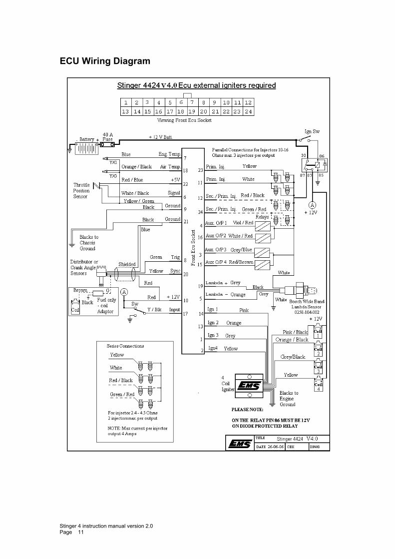
ECU Wiring Diagram
Stinger 4 instruction manual version 2.0 Page 11
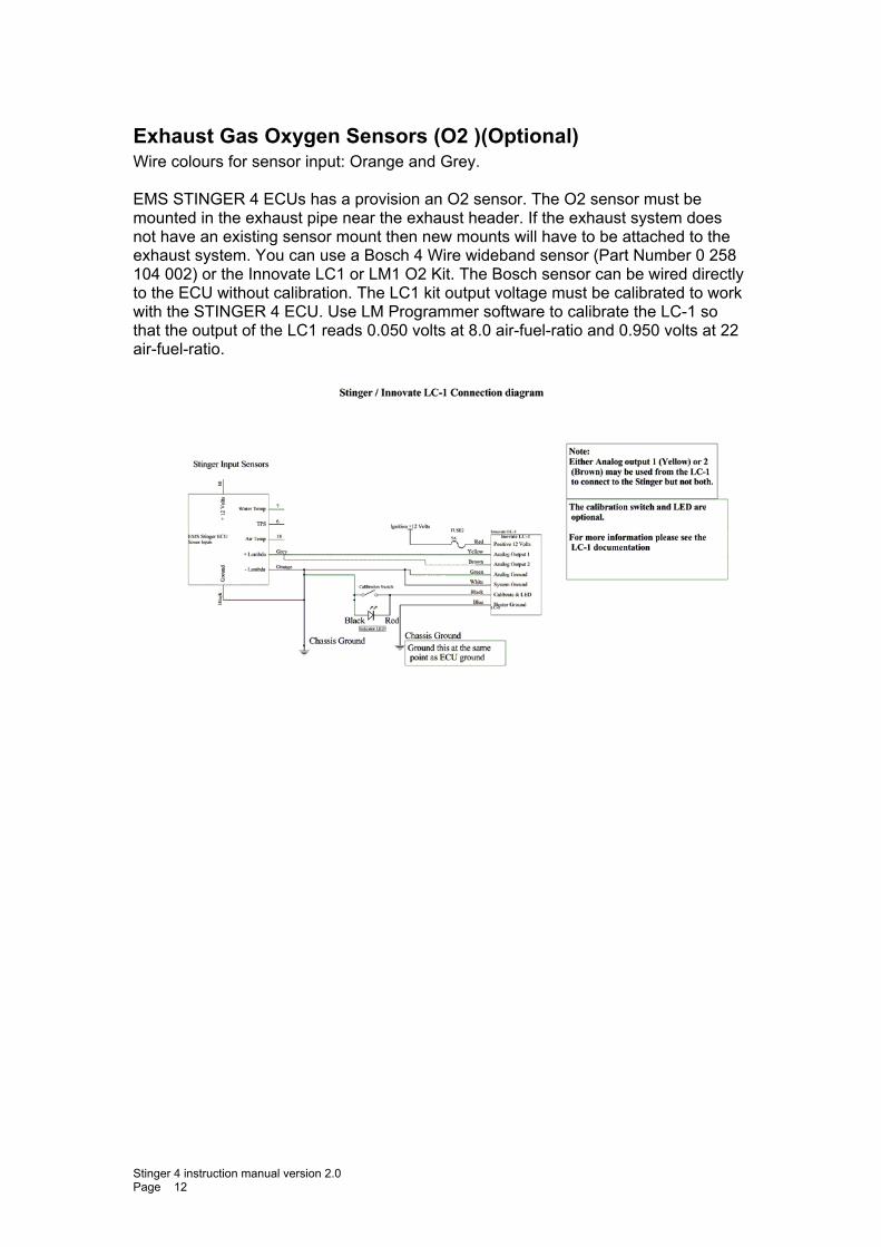
Exhaust Gas Oxygen Sensors (O2 )(Optional) Wire colours for sensor input: Orange and Grey. EMS STINGER 4 ECUs has a provision an O2 sensor. The O2 sensor must be mounted in the exhaust pipe near the exhaust header. If the exhaust system does not have an existing sensor mount then new mounts will have to be attached to the exhaust system. You can use a Bosch 4 Wire wideband sensor (Part Number 0 258 104 002) or the Innovate LC1 or LM1 O2 Kit. The Bosch sensor can be wired directly to the ECU without calibration. The LC1 kit output voltage must be calibrated to work with the STINGER 4 ECU. Use LM Programmer software to calibrate the LC-1 so that the output of the LC1 reads 0.050 volts at 8.0 air-fuel-ratio and 0.950 volts at 22 air-fuel-ratio.
Stinger 4 instruction manual version 2.0 Page 12

Power Connections Black Wire (Ground)
Find a good ground point on the chassis and connect the black wire. Be sure not to connect this wire to the engine block.
Red wire
The STINGER 4 ECU does not need a permanent +12 volt supply. Connect this wire to the ignition switched + 12 volts.
Stinger 4 instruction manual version 2.0 Page 13
Ignition Modules Wire colours for Ignition outputs 1: Pink (14) 2: Orange/Red (13) 3: Grey/Black (1) 4: Yellow/Red (2) Warning: These ECUs do not have built-in igniters. Do not connect any ignition output directly to the coil. You must use external ignition modules. Connecting the ECU to an ignition module(s) before setting the ignition fire edge correctly may damage the module(s) and coils. The STINGER 4 ECUs can drive most OEM igniters but you must we aware of the trigger signal required to drive the igniter. Some igniters require a rising signal and others a falling signal. Getting the signal wrong can cause the igniter and coil to overheat. EMS igniters and most OEM igniters are negative fire igniters (Falling edge). These ECUs can control smart and dumb igniters. Smart igniters will self-dwell the coil, dumb igniters will follow the signal from the ECU. If you are using smart igniters then still set the dwell to the correct value for your coils and the igniter will follow the signal from the ECU. It is important to set the correct dwell via the management software. Over dwelling a coil will only cause it to overheat, under dwelling will not allow the coil to build enough electrical energy. A good starting point is 3.5 mS. The STINGER 4 ECU will fire the ignition outputs in sequential order. That is it will fire output 1, 2, 3 and 4. You will need to wire these in the firing sequence of your engine.
Wiring Injectors Wire colours for injector outputs 1: Yellow (23) 2: White (11) 3: Red/Black (12) 4: Green/Red (24) The STINGER 4 ECU controls injectors by pulling to ground. This means that all injectors have a common positive 12 volt rail. The injectors are fired sequentially. You must ensure that the combined injector resistance for each output is not less than 1.2 ohms. For example connecting 2 X 1.2 ohm injectors in parallel will give a resistance of 0.6 ohms. This would cause the injector output drivers to current limit, if this were to happen then the injectors would not open consistently. All STINGER 4 ECUs automatically adjust the injector duty to compensate for battery voltage fluctuations ranging from 7 to 16 volts.
Stinger 4 instruction manual version 2.0 Page 14
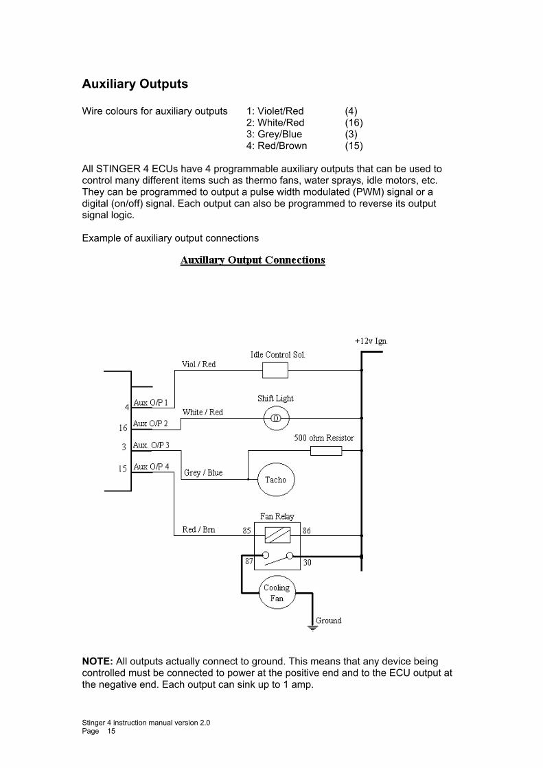
Auxiliary Outputs Wire colours for auxiliary outputs 1: Violet/Red (4) 2: White/Red (16) 3: Grey/Blue (3) 4: Red/Brown (15) All STINGER 4 ECUs have 4 programmable auxiliary outputs that can be used to control many different items such as thermo fans, water sprays, idle motors, etc. They can be programmed to output a pulse width modulated (PWM) signal or a digital (on/off) signal. Each output can also be programmed to reverse its output signal logic. Example of auxiliary output connections
NOTE: All outputs actually connect to ground. This means that any device being controlled must be connected to power at the positive end and to the ECU output at the negative end. Each output can sink up to 1 amp.
Stinger 4 instruction manual version 2.0 Page 15
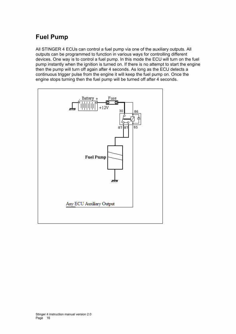
Fuel Pump All STINGER 4 ECUs can control a fuel pump via one of the auxiliary outputs. All outputs can be programmed to function in various ways for controlling different devices. One way is to control a fuel pump. In this mode the ECU will turn on the fuel pump instantly when the ignition is turned on. If there is no attempt to start the engine then the pump will turn off again after 4 seconds. As long as the ECU detects a continuous trigger pulse from the engine it will keep the fuel pump on. Once the engine stops turning then the fuel pump will be turned off after 4 seconds.
Stinger 4 instruction manual version 2.0 Page 16
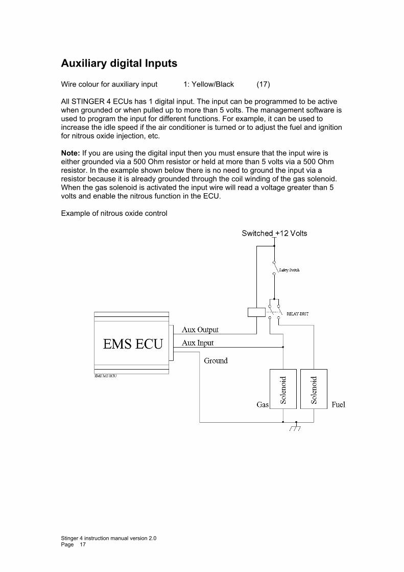
Auxiliary digital Inputs Wire colour for auxiliary input 1: Yellow/Black (17) All STINGER 4 ECUs has 1 digital input. The input can be programmed to be active when grounded or when pulled up to more than 5 volts. The management software is used to program the input for different functions. For example, it can be used to increase the idle speed if the air conditioner is turned or to adjust the fuel and ignition for nitrous oxide injection, etc. Note: If you are using the digital input then you must ensure that the input wire is either grounded via a 500 Ohm resistor or held at more than 5 volts via a 500 Ohm resistor. In the example shown below there is no need to ground the input via a resistor because it is already grounded through the coil winding of the gas solenoid. When the gas solenoid is activated the input wire will read a voltage greater than 5 volts and enable the nitrous function in the ECU. Example of nitrous oxide control
Stinger 4 instruction manual version 2.0 Page 17
ECU Programming and Configuration
Management Software Operating system: Windows 2000, Windows ME, Windows XP and Vista. PC Requirements: 1.2 GHz processor VGA colour display with 800x600 resolution (preferably 1024x768) 128MB of memory 40 MB of free Disk space
Installing the software Installation is similar to any other windows software. 1. Insert the CD-ROM into your PC’s CD-ROM drive. 2. The CD should auto-run the installation software. If the installation software appears then go to step 6. 3. Double click on the “My Computer” icon on the desktop. 4. Double click on the CD-ROM icon to open the CD-ROM. 5. Double click on the “EMSInstaller.EXE” icon to start the installation software. 6. Select install the STINGER 4 software. 7. Follow the installation steps leaving the default values. When the installation is complete you should find the STINGER 4 Management Software icon on you desktop.
Going Online with the Software First ensure that you have your programming cable attached to the ECU and the other end connected to your laptop. Double-click on the STINGER 4 Management Software icon on your desktop to run the application. After the application is running, turn on the ignition to power up the ECU. If all is well you should see the message “Read from ECU”. Press the Yes button to read or NO if you do not want to read from the ECU. If you did not receive this message then you may need to tell the software which COM port number to use. This is done from the “Application Settings” -> “Operational Parameters” menu options. Select the correct COM port number, press the “Save” button and then re-start the EMS STINGER 4 Software.
Stinger 4 instruction manual version 2.0 Page 18
Loading a base map All STINGER 4 ECUs come pre-loaded with a base map. If you requested a map for a particular engine then this would have been pre-loaded (if available). The software also has a selection of base maps for many different engines that you can choose from. Go-to the “File” then “Open Tune File” Option and then go-to the “Base Maps” folder, select a map that is suitable for your engine and press the “Open” Button. To write this map into the ECU go-to “ECU” then “Write to ECU” menu option. When the progress bars at the bottom of the screen have stopped the map will have been written to the ECU. Warning: The base maps are not intended for driving. These should only be used to ensure that the ECU is installed correctly and the engine starts. The engine must be properly tuned and tested at a mechanical workshop before attempting to drive the vehicle.
Stinger 4 instruction manual version 2.0 Page 19
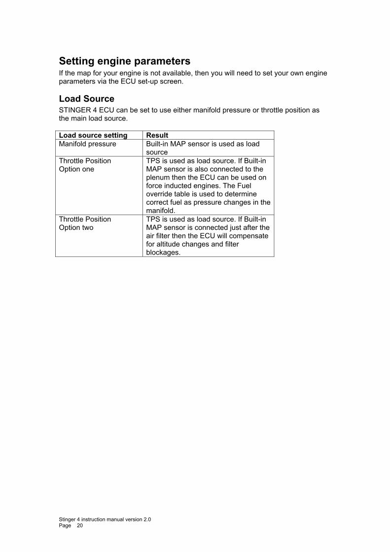
Setting engine parameters If the map for your engine is not available, then you will need to set your own engine parameters via the ECU set-up screen.
Load Source STINGER 4 ECU can be set to use either manifold pressure or throttle position as the main load source. Load source setting Result Manifold pressure Built-in MAP sensor is used as load
source Throttle Position Option one
TPS is used as load source. If Built-in MAP sensor is also connected to the plenum then the ECU can be used on force inducted engines. The Fuel override table is used to determine correct fuel as pressure changes in the manifold.
Throttle Position Option two
TPS is used as load source. If Built-in MAP sensor is connected just after the air filter then the ECU will compensate for altitude changes and filter blockages.
Stinger 4 instruction manual version 2.0 Page 20
Engine Set-up Parameters
Ignition fire edge This parameter must be set according to the igniter module you are using. EMS igniters and most OEM igniters work with a falling firing edge. This means that the ignition output of the ECU is held at a high voltage for the duration of the dwell period and then switched off when the coil needs to fire. Rising edge modules work in the opposite manner. It is important to set this correctly to prevent coils and igniters from being overloaded.
Ignition Delay Compensation This parameter is set if you are using a CDI system. All CDIs have a delayed response from trigger to fire. This delay can cause your ignition timing to fire slightly retarded at high RPM. If you know the delay of your CDI then set it here so the ECU can compensate for the delay. A typical value would be around 16 to 30 microseconds.
Ignition Dwell Ignition dwell time is the duration in milliseconds that the coil is charged before being fired. The time will vary between different ignition and coil systems. Typically 3.5mS is a good point to start. Setting this value to zero (0) will cause the ECU to give a 50% duty and is not recommended except for some CDI systems.
Injector Ohms The ECU uses this value to determine the injector latency and compensate for it. Low ohm injectors have a faster response time than high ohm injectors. So by setting the correct injector resistance will allow the ECU to compensate for injector latency more accurately. This also works in conjunction with battery voltage. As the battery voltage varies from 13.8 volts, the ECU will adjust the injector duty to compensate. This enables the ECU to work with battery voltages from 7 volts up to 16 volts while maintaining a steady air/fuel ratio. You can do a test by using a Multi-Meter. Unplug the electrical harness of one of the injectors and place the Multi-Meter's probes on the injector pin outs (where the electrical harness clips on) and measure the resistance. When you have a reading adjust this parameter to the closest setting. Note: If you are using staged injectors with a different value of Ohms, set the Ecu to the value corresponding to the primary injectors.
Soft Rev Limit Set this parameter to the RPM you want the engine limited. The rev limiter cuts the ignition in a specific sequence to prevent spark plugs from fowling when rev limiting. It can be set a little lower than the absolute maximum RPM and the hard rev limiter can be set to the absolute maximum RPM. This will give double protection from over revving an engine. To disable the Soft Rev Limiter set it to 0 RPM.
Stinger 4 instruction manual version 2.0 Page 21
Hard RPM Limit Set this parameter to the absolute maximum RPM you want the engine limited. This method will completely cut the ignition at the selected RPM and enable it again when the RPM has dropped below the set value. This will prevent an engine from over revving. To disable the Hard Rpm Limiter set it to 0 RPM.
Boost Cut This parameter will prevent forced inducted engines from over boosting. Select the allowable pressure limit before cutting the ignition. The ignition will restart once the pressure has dropped below the value set. If boost cut is not required select OFF.
Deceleration Fuel Cut This parameter is used to cut the fuel when the engine vacuum falls below the set value. This is useful for controlling emissions. You would use this parameter to stop injecting fuel when the engine is used to slow the momentum of the vehicle. An example would be decelerating the vehicle down a steep hill by closing the throttle. Select at which vacuum value you would like the computer to cut fuel. The fuel injection is stopped when the vacuum is stronger than the selected value. If this feature is not required select No Fuel Cut.
Use Throttle Sensor This parameter is only used for controlling flood mode and to effect the acceleration enrichment response times. Ticking this parameter will enable the ECU to respond to TPS changes. Other functions like using the TPS as a main load source or special functions such as anti-lag and controlling auxiliary outputs will not be affected. If a throttle position sensor is fitted then it is recommended that you use it because it will enable the ECU to respond instantly to sudden changes in engine load. If there is no TPS connected then ensure that this parameter is not ticked.
Stinger 4 instruction manual version 2.0 Page 22
Acceleration Enrichment The following 5 parameters work together so you can achieve a smooth acceleration response.
Sensitivity The sensitivity parameter works in conjunction with “aspiration” and “supercharger boost”. These three parameters control the acceleration enrichment response to sudden changes in engine load. The throttle position sensor must be used for these parameters to have any effect. This parameter has 3 settings to choose from Coarse (0), Medium (1) and Fine (2). You may need to experiment with these to obtain the best response time. The coarse setting is used for normal throttle body sizes medium is for a large throttle bodies and fine is for very large throttle bodies or multiple throttle bodies. This function will only appear on screen if a throttle position sensor has been fitted and selected in the "ECU Set-up" screen. These settings affect both the amount of fuel and how quickly the accelerator pump fuel enrichment is activated.
Intake Induction This parameter works in conjunction with Sensitivity. Acceleration enrichment responses are different for turbo charged or normally aspirated engines than for supercharged engines. There is a time delay between opening the throttle and the air rushing in to fill the manifold. For turbo charged or normally aspirated engines this may be only milliseconds but for supercharged engines it is almost instant. This parameter instructs the ECU to behave according to the aspiration of the engine. Select Normal / Turbo for normally aspirated or turbo charged engines. Select Super Charged for supercharged (positive displacement) engines.
Super Charger Boost This parameter works in conjunction with Sensitivity and Intake Induction. It is only for supercharged engines, not for turbo charged engines. Set this value to the max boost pressure that will be reached.
Accelerator Enrichment Sudden engine load changes are detected in two ways. One is by detecting sudden manifold pressure changes and the other is by throttle position changes (if TPS is used). When using TPS there is a 3 percent dead band before the accelerator pump is activated. The "Acceleration Enrichment" parameter sets a percentage of extra fuel to be added for immediate acceleration. The percentage is based on values from the main fuel map thus ensuring that the enrichment follows the engines volumetric efficiency. Through acceleration testing, adjust the ECU until you have achieved a satisfactory engine response. If you can’t get a good response then you may need to adjust the sensitivity as well.
Stinger 4 instruction manual version 2.0 Page 23
The value in this setting represents a percentage increase of fuel when the accelerator is pushed. This is normally set between 5 and 30%. The duration of the increase is defined in the "Enrichment Duration" setting. NOTE: You will need to place an amount in the "Enrichment Duration" setting so you can correctly fine tune the accelerator enrichment. When tuning the fuel maps at steady state, temporarily set the acceleration enrichment to 0 and don't forget to reset it back afterwards.
Enrichment Duration Enrichment Duration sets the duration for which the fuel is added. Through acceleration testing, adjust this parameter until you have reached a satisfactory engine response. You will need to move back and forward between Acceleration Enrichment and Enrichment Duration to get the best response. Enrichment Duration is the number of power strokes fired with extra fuel being added. Normally set to 30. but can be reduced or increased as needed. For example, setting a value of 30 cause the enrichment to last for 30 power strokes which is equivalent to 10 crank revolutions. When tuning the fuel maps at steady state, temporarily set this to 0 and don't forget to reset it back afterwards.
Stinger 4 instruction manual version 2.0 Page 24
Throttle Position Sensor Calibration (only if a TPS is fitted) The closed throttle and open throttle settings cannot be adjusted manually. You must follow the procedure described below. It is important that the calibration be done if you will be using the TPS as the main engine load source. Before commencing, while the engine is turned off, make a visual and physical check of the throttle to see that it does fully open and close.
Calibrate Closed Throttle With your throttle closed, press the "Read Closed Throttle" button. The system will place a number into the field. This is the TPS voltage represented as a number when the throttle is closed. You should see a number between 0 and 300.
Calibrate Open Throttle Open your throttle fully, and then press the "Read Open Throttle" button. The system will place a number into the field. This is the TPS voltage represented as a number when the throttle is open. You should see a number between 700 and 1000. This function can only be used if a throttle position sensor has been fitted and the Use Throttle sensor check box is ticked. NOTE: If, for any reason the TPS is moved then you should recalibrate the sensor.
Stinger 4 instruction manual version 2.0 Page 25
Closed Loop Lambda All STINGER 4 ECUs offer two closed loop lambda control modes. Narrow band and wide band.
Narrow Band If you only have a narrow band sensor connected then set the operation mode to Narrow Band. In this mode the system will only detect if the air/fuel ratio is above or below the stoic value and try to maintain this value. Stoic is equal to lambda value 1 or air/fuel ratio 14.7 for petrol engines. The Target A/F Ratio cannot be selected in this mode.
Wide Band By selecting either Bosch 4 wire or 5 wire adapter will put the ECU into wide band mode. The Bosch 4 Wire mode uses the Bosch 4 wire sensor (Bosch Sensor Number 0 258 104 002). All STINGER 4 ECUs can read this sensor directly and provide accurate air fuel ratio values that are compensated for sensor temperature variations. The Bosch 5 wire adapter mode uses the LC1 or LM1 lambda kit from Innovate. This kit uses the Bosch 5 wire sensor and a control unit. In this mode the ECU reads either Analog 1 or 2 of the LC-1 output. Before the LC-1 can be used it must be calibrated. Use LM Programmer software to calibrate the LC-1. Set the output to read 0.050 volts for an air fuel ratio of 8.0 and 0.950 volts for an air fuel ratio of 22.
Programming the close loop lambda function This function is intended for light driving conditions and idle. It should be used to control exhaust emissions. The Allowable Change parameter determines the maximum automatic fuel percentage adjustment allowed. This setting prevents the ECU form over-adjusting the fuel delivery if there is a lambda sensor failure. The Operating Range parameter determines the vacuum range in which the close loop function will work. The range starts from minus 100 kPa and ends at the value set by this parameter. The closed loop control will turn off when the engine is above the selected vacuum (closer to zero) and start again once the engine vacuum goes below the selected level. The Target A/F Ratio parameter sets the air fuel ratio you want to maintain. The ECU will automatically adjust the fuel delivery in order to achieve the selected target or is forced to stop when it reaches the allowable change limit.
Stinger 4 instruction manual version 2.0 Page 26
Timing Sensor Set-up The ECU uses the signals from the trigger and sync sensors to follow the engine cycle. In Normal Mode the sync signal is used to tell the ECU that the next trigger will be number one BTDC. All STINGER 4 ECUs can accept hall, optical and magnetic sensors using the same input wire. Some after market ECUs require a complex calibration procedure to calibrate a magnetic sensor to the ECU. With the EMS STINGER 4 ECUs this is not necessary because it will automatically self-learn the magnetic sensor signals. Also, the ecu will trigger with a trace zero crossing signal. This method provides pin-point timing accuracy over the entire rev range.
Trigger (ref) sensor type This parameter sets the ECU to use a Hall, Optical or magnetic sensor for the trigger signal. The same input wire can be used to read signals from any of these sensors.
Sync (home) sensor type This parameter sets the ECU to use a Hall, Optical or magnetic sensors for the sync (home) signal. The same input wire can be used to read signals from any of these sensors. If the sensor type is Hall or Optical then set this parameter to “Hall/Optical”. Hall and Optical sensors are usually 3 wire sensors that produce a square wave signal. These sensors usually require a regulated power supply that can be obtained from the red 8 volt wire inside the shielded sub-loom. If the sensor type is magnetic then set this parameter to “Magnetic” Magnetic sensors are 2 wire sensors. They produce a sine wave signal. No power supply is required for these sensors. WARNING: If the red 8 volt power supply wire is not being used then it must be properly isolated to prevent short-circuiting.
Stinger 4 instruction manual version 2.0 Page 27
Trigger Edge The trigger edge determines whether the computer is triggered by the positive or negative edge of the trigger signal. For magnetic sensors the trigger edge must be set to rising. DANGER! Disconnect the ignition coils before rotating the engine by hand. Depending on the sensor wheel slots or teeth, the signal will either be rising or falling at somewhere between TDC & 15 degrees BTDC. If unknown, connect a multi meter from the trigger wire to ground and watch the voltage level change while turning the engine slowly by hand to determine if the signal is rising or falling. If rising, select Rising (+) If falling, select Falling (-)
Sync Edge The sync edge determines whether the computer is synchronised by the positive or negative edge of the sync signal. For magnetic sensors the sync edge must be set to rising. DANGER! Disconnect the ignition coils before rotating the engine by hand. Depending on the sensor wheel slots or teeth, the signal will either be rising or falling. If unknown, connect a multi meter from the sync wire to ground and watch the voltage level change while turning the engine slowly by hand to determine if the signal is rising or falling. If rising, select Rising (+) If falling, select Falling (-)
Trigger pull-up resistor This parameter is only used for hall or optical sensors. It should be set to ON if the ECU is used as a stand-alone system and OFF it the trigger sensor is being shared with the OEM ECU. Sometimes, if the sensor is shared then the signal may be a little weak. In this case you can set this parameter to ON. This will allow a little more current to flow and improve the rise time of the signal.
Sync pull-up resistor This parameter is only used for hall or optical sensors. It should be set to ON if the ECU is used as a stand-alone system and OFF it the sync sensor is being shared with the OEM ECU. Sometimes, if the sensor is shared then the signal may be a little weak. In this case you can set this parameter to ON. This will allow a little more current to flow.
Stinger 4 instruction manual version 2.0 Page 28
Ignition Set-up STINGER 4 ECUs can read one of many selectable trigger patterns. Each engine provides a trigger pattern that the ECU can use to synchronize itself to the engine cycle. Some engine manufacturers use patterns that are specific to their engines and other manufactures use systems developed by third party companies such as Bosch.
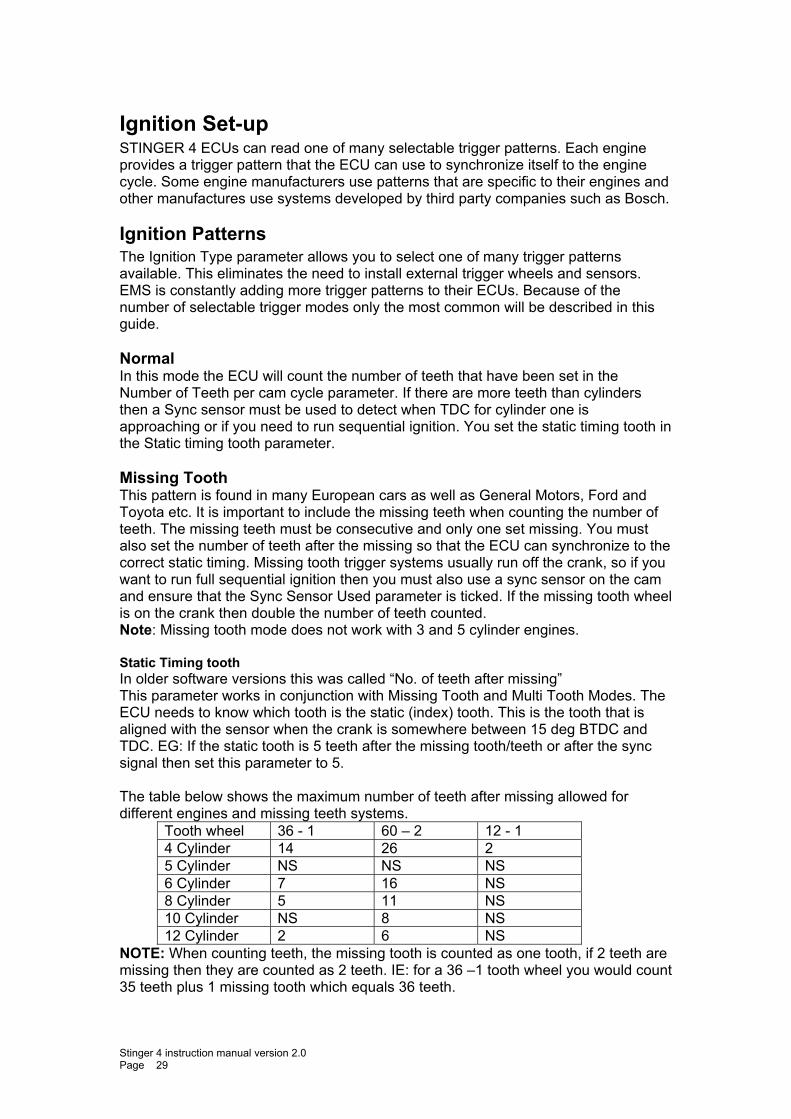
Ignition Patterns The Ignition Type parameter allows you to select one of many trigger patterns available. This eliminates the need to install external trigger wheels and sensors. EMS is constantly adding more trigger patterns to their ECUs. Because of the number of selectable trigger modes only the most common will be described in this guide. Normal In this mode the ECU will count the number of teeth that have been set in the Number of Teeth per cam cycle parameter. If there are more teeth than cylinders then a Sync sensor must be used to detect when TDC for cylinder one is approaching or if you need to run sequential ignition. You set the static timing tooth in the Static timing tooth parameter. Missing Tooth This pattern is found in many European cars as well as General Motors, Ford and Toyota etc. It is important to include the missing teeth when counting the number of teeth. The missing teeth must be consecutive and only one set missing. You must also set the number of teeth after the missing so that the ECU can synchronize to the correct static timing. Missing tooth trigger systems usually run off the crank, so if you want to run full sequential ignition then you must also use a sync sensor on the cam and ensure that the Sync Sensor Used parameter is ticked. If the missing tooth wheel is on the crank then double the number of teeth counted. Note: Missing tooth mode does not work with 3 and 5 cylinder engines. Static Timing tooth In older software versions this was called “No. of teeth after missing” This parameter works in conjunction with Missing Tooth and Multi Tooth Modes. The ECU needs to know which tooth is the static (index) tooth. This is the tooth that is aligned with the sensor when the crank is somewhere between 15 deg BTDC and TDC. EG: If the static tooth is 5 teeth after the missing tooth/teeth or after the sync signal then set this parameter to 5. The table below shows the maximum number of teeth after missing allowed for different engines and missing teeth systems.
Tooth wheel 36 - 1 60 – 2 12 - 1 4 Cylinder 14 26 2 5 Cylinder NS NS NS 6 Cylinder 7 16 NS 8 Cylinder 5 11 NS 10 Cylinder NS 8 NS 12 Cylinder 2 6 NS
NOTE: When counting teeth, the missing tooth is counted as one tooth, if 2 teeth are missing then they are counted as 2 teeth. IE: for a 36 –1 tooth wheel you would count 35 teeth plus 1 missing tooth which equals 36 teeth.
Stinger 4 instruction manual version 2.0 Page 29
Nissan mode 1 This is used for multi-coil applications using a cam mounted crank angle sensors eg: CA18, RB20, VG30, SR20. You can select to run wasted spark by setting the number of igniters to be half the number of cylinders or full coil-on-plug (sequential) by setting the number of igniters to be equal to the number of cylinders. These cam mounted sensors have 2 signals. The sensor that reads 180 teeth must connect to the sync wire and the one that reads 4 or 6 teeth (depending on number of cylinders) connect to the trigger wire. Set both sensor types to hall, trigger edge to + (Rising), sync edge to – (Falling) and the number of trigger teeth to “one tooth per cylinder”. Nissan mode 2 This is used for multi-coil applications when a distributor is used instead of a cam mounted crank angle sensor eg FJ20, RB30, ET PULSAR. You can also choose to run wasted spark or full sequential by selecting the number of igniters and cylinders as per Nissan mode 1. Set both sensor types to hall, trigger edge to + (Rising), sync edge to – (Falling) and the number of trigger teeth to “one tooth per cylinder”. Note: All Nissan Crank Angle Sensors need to be repositioned. Nissan sensors are normally set to 60 deg BTDC. The STINGER 4 ECU requires the trigger sensor to be positioned approx. 5 - 15 Deg. BTDC. If your Nissan has a distributor with one coil and you will continue to use one coil then do not connect the sync sensor, only the trigger sensor. Set the Ignition type parameter to Normal and Trigger edge to + (Rising). Subaru WRX from 2001 This mode is used for 4 and 6 cylinder Subaru boxer engines. Set the number of cylinders to 4 or 6 and number of trigger teeth to “one tooth per cylinder”. You can select to run wasted spark by setting the number of igniters to be half the number of cylinders or full coil-on-plug (sequential) by setting the number of igniters to be equal to the number of cylinders. If running sequential ignition (coil on plug) then you must use a sync sensor and the Sync Sensor Used parameter must be ticked. Subaru Boxer Engines Pre 2001 This mode is used for 4 cylinder Subaru engines only. These have magnetic sensors. It is critical that they are connected with the correct polarity. If they are not connected correctly the engine will not run. Set number of cylinders to 4, Number of igniter to 2, Trigger sensor to Magnetic, Sync sensor to Magnetic, Trigger edge to + (Rising) and Sync Edge to + (Rising). You can still use 4 coils with a 4 coil igniter but must run wasted spark by firing 2 igniter channels with 1 ignition output.
Stinger 4 instruction manual version 2.0 Page 30
No. Of teeth per cam cycle Use this parameter to set the number of teeth per cam cycle. Some trigger wheels run off the crank and others run off the cam. STINGER 4 ECUs are sequenced by cam cycles because this represents a full engine cycle. It is important that you enter the correct number of teeth in this parameter. If the trigger wheel is running off the crank then you must double the number of teeth counted. If the trigger wheel is running off the cam then count the teeth and use that number.
Sync Sensor Used This parameter works in conjunction with missing tooth mode and Subaru from 2001 mode if you want to fire injectors and igniters sequentially (one coil per plug and one injector per port). Because most missing tooth wheels run from the crank or run the same RPM as the crank the ECU will receive 2 index signals per cam cycle and therefore true sequential is not possible. By reading a TDC sync signal from a cam or distributor wheel the ECU can then run in true sequential mode.
Running more than 1 tooth per cylinder Set the Ignition Type parameter to “Normal”. If there are more trigger teeth per cam cycle than cylinders, then set the number of teeth per cam cycle parameter to the number of teeth counted. It is important to remember that 1 cam cycle is equal to 2 crank revolutions therefore if the trigger wheel is running off the crank then you must double the count. Note: The number of teeth per cam cycle must divide down equally by the number of cylinders. Below is an example for a 24-tooth wheel on a 4-cylinder engine. eg. 24 teeth divided by 4 cylinders = 6. This is ok. eg. 18 teeth divided by 4 cylinders = 4.5. WILL NOT WORK! The teeth must be spaced evenly and a sync sensor MUST be used. The trigger tooth directly after the sync sensor tooth is the index tooth and is usually positioned in front of the trigger sensor when the engine is somewhere between TDC and 15 deg BTDC on cylinder number 1.
Running 1 tooth per cylinder In situations where there is 1 tooth per cylinder in a cam cycle you can select either “one tooth per cylinder” or a value equal to the number of cylinders in the “No of teeth per cam cycle” parameter. A sync sensor is not required if a single ignition coil with a distributor is used because the ECU will fire the ignition output once per trigger signal and the distributor will distribute the ignition to the correct cylinder. However, If you need to run coil-on-plug ignition then you must use a sync sensor on the cam. The trigger tooth directly after the sync sensor tooth is the index tooth and is usually positioned in front of the trigger sensor when the engine is somewhere between TDC and 15 deg BTDC on cylinder number 1.
Stinger 4 instruction manual version 2.0 Page 31
Tuning an Engine This is best done using an engine or chassis dyno. It is not good practice to try and tune an engine while driving on the road. This would be dangerous to yourself and others.
Tuning Fuel and Ignition Maps You can tune an engine by using the built-in MAP sensor, a Throttle position sensor or one of the Analog inputs as a primary load source. The tuning processes for each method will be the same. Using the internal MAP sensor to read engine load The internal Manifold Absolute Pressure sensor is a 5 bar sensor that can read pressures from –100 Kpa (full vacuum) to 200 Kpa (30 Psi). The tuning grids have a possible 40 user definable R.P.M columns and 21 user definable load rows which give the tuner 3072 individual load points. The ECU comes with pre-programmed fuel map settings at 500 R.P.M increment. These are only a starting point and can easily be changed. If this is the first time you have set-up a particular engine you should use the Fuel Trim function in the Trims section of the tuning screen to help get the engine started. Using a Throttle Position Sensor (TPS) to read engine load A throttle position sensor can be used to read engine load by detecting the position of the throttle from fully closed to fully open. This is represented as a percentage from 0 to 100 percent. The tuning grids have a possible 40 user definable R.P.M columns and 21 user definable position percentage (load) rows. It is extremely important that a good quality TPS be used when tuning using TPS load sensing. Make sure that the TPS is a variable resistance (potentiometer) type and that it is properly calibrated (see Throttle Position Sensor Calibration for details). Ensure that the sensor reading is repeatable after calibrating. Watch the TPS gauge on the tuning screen and make sure that the reading follows your foot movement and reaches 100% when fully pressed, and then returns back to 0 %. Do this a number of times to ensure that the reading returns to 0% every time. This load source selection relies heavily on the TPS sensor, so ensure it is operating before commencing to tune. Using fuel trims for first time engine start up It is much easier to get the engine running for the first time by using the fuel trim adjustment. This adjustment is found in the trims section of the tuning screen. If you see that the engine is difficult to start because it is too lean or too rich then you can increase or decrease the fuel delivery until the engine starts easily. Adjusting Fuel / Ignition Maps Bring the engine up to the desired R.P.M / load and press the space bar, this will position the cursor onto the R.P.M / load point that matches the actual engine R.P.M / Load. Adjust the fuel or ignition setting by the pressing the “Pg up” or “Pg dn” keys to increase or decrease the injector mS or Ignition timing until the desired value is reached. Repeat this for every load point on the tuning grid.
Stinger 4 instruction manual version 2.0 Page 32
Using the cross hairs Cross hairs are provided on the tuning grids to help you bring the engine load/RPM up to match the load cell being tuned. When the cross hairs are centred in the load cell this means that this is the best time to adjust the cell value. IMPORTANT
a) The engine must be up to operating temperature before tuning. b) The engine must be held as close as possible to load / Rpm point being
adjusted. c) Temporarily disable the acceleration enrichment while tunning.
Clear Flood Mode Clear flood mode is used when the engine is flooded. A throttle position sensor must be fitted. When the throttle is pressed passed 90% while cranking, the Ecu will not fire injectors. This allows the engine to clear any excess fuel in the manifold.
Tuning grid command keys These commands are also available on a pop-up menu when you right-click on the tuning grid. Page-Up and Page-Down Keys Press the page-up key to increase the value of a cell by 1 and Page-down to decrease the value by 1. You can also select a range of cells and increase or decease them by pressing the Page-up and Page-down keys. Use Shift and any combination of arrow buttons to highlight / Select a range of grid cells that you want to adjust and then press the Page-up or Page-down key to increase or decrease each cell by 1. Auto Trace (Space Bar) You can automatically position the cursor onto the load/rpm point of an engine while the engine is running by pressing the space bar. If you keep the space bar pressed then the system will trace the engine as it moves through each load point. Each load point will be highlighted with a green boarder indicating the load path of the engine. You can clear the path by pressing the "Clear Trace" button or "alt + c" NOTE: When barometric compensation is active the load point that the ECU is using may not match with the Manifold Pressure being displayed on the live gauges. This is because the ECU now determines the load point based on volumetric efficiently. Insert RPM Column (Ctrl +Right Arrow or Shft+Alt+C) Press Ctrl then Right Arrow to insert a new RPM column in between the current cursor position and the column to the left. This will push all RPM columns from the cursor (including the cursor) to the right and then insert a new one.
Stinger 4 instruction manual version 2.0 Page 33
Insert Load Row (Ctrl + Down Arrow or Shft+Alt+R) Press Ctrl then Down Arrow to insert a new load row (TPS/KPA/Analog) in between the current cursor position and the row above. This will push all load rows from the cursor (including the cursor) down and then insert a new one. Delete RPM Column (Ctrl + Left Arrow or Shft+Ctrl+C) Press Ctrl then Left Arrow to Delete the RPM column immediately left of the cursor. This will pull all columns from the cursor (including the cursor) to the left one column. Delete Row (Ctrl + Up Arrow or Shft+Ctrl+R) Press Ctrl then Up Arrow to delete the load row (TPS/KPA) immediately above the cursor. This will pull all rows from the cursor (including the cursor) up one row. Interpolate or Fill (Shift + Left or Right or Up or Down Arrows) Use Shift and any combination of arrow buttons to highlight / Select a range of grid cells that you want to automatically fill or interpolate. Once selected, use Alt+Ctrl+R if you want to interpolate/fill using the top and bottom rows as the reference points. This means that the system will automatically calculate all the cell values for each cell in between the top and bottom selected rows. Or use Alt+Ctrl+C if you want to interpolate/fill using the left and right columns as the reference points. This means that the system will automatically calculate all the cell values for each cell in between the left most and right most selected rows. Alt+Ctrl + R: Automatically fill all selected cells from left to right with values based on the value in the first (left) and last (right) selected cells. Alt+Ctrl + C: Automatically fill all selected cells from top to bottom with values based on the value in the first (top) and last (bottom) selected cells. Create new Tuning grid (Alt+Ctrl + T) Create or change a tuning grid. This will allow you to change the number of columns or rows in a tuning grid. This is normally used on first time set-up. Changing Existing RPM or Load index values (Alt+Ctrl + H) Change the load and RPM value for the selected column/row. Use this to adjust the RPM and load for the selected grid cell. Instead of Ctrl + H, you can double click the grid in the correct row/column.
Stinger 4 instruction manual version 2.0 Page 34

Changing the page-up & page-down resolution This is only used on the ignition grid. You can select the amount of degrees the system increments or decrements each time you press the page-up/down key. Selecting 0.2 on the resolution selection box will cause each page-up/down key press to change the timing value by 0.2 degrees. If 2.0 degrees is selected then each press will cause a change of 2 degrees.
Stinger 4 instruction manual version 2.0 Page 35
Tune Analyser NOTE: When barometric compensation is active the load point that the ECU is using may not match with the Manifold Pressure being displayed on the live gauges. This is because the ECU now determines the load point based on volumetric efficiently. Tune Analyser is a feature designed by EMS to assist in tuning an engine to its peak performance by allowing you to log the average A/F ratio at each load point. You can then analyse the data and make adjustments to the fuel map or have the system automatically adjust the fuel map by comparing the target A/F Ratios with the actual A/F ratios and adjusting the fuel map accordingly. Running the Analyser You can have the system automatically adjust the fuel map if you want. First you must set the target A/F ratio for each load point. To start the analyser you must first press the analyser settings button and select to use either A/F input 1, 2 or both. Then press the Run Analyser button while the engine is running so the system will start to constantly monitor the A/F ratio at each load point. The accuracy of the analysis will increase as you run the engine for longer periods. Press the Run Analyser button again to stop monitoring. You can see how many times each load point was recorded by placing the cursor on a grid cell and looking at the read count field just above the buttons. The load points that have been analysed will show highlighted on the Fuel Map grid. Applying changes Automatically You can have the system automatically adjust the fuel map if you want. First you must set the target A/F ratio for each load point. Press the Target A/F Ratio tab and enter the target A/F ratio for each load point you want adjusted. When you press the Apply Changes button the system will automatically adjust the fuel delivery table by comparing the actual A/F ratios with the target ones and adjust the fuel map accordingly. Do this repeatedly until you have achieved a good tune. You may still need to smooth out some peaks and valleys if you want. TIP: You can also move the actual A/F readings over to the Target map by pressing the Actual to Target button and then adjust each target load point to the desired value. Any load point with a 0 (zero) target value will not be adjusted. NOTE: You can exclude cells from the being applied by selecting the cell and pressing ALT+X or the "Exclude from apply" button. This can be done from the either the Fuel grid or Tune Analyser grid. Applying changes Manually You can apply changes directly on the fuel grid. After you have analysed and set the A/F targets for the load points you want to adjust you will see that the cells on the fuel delivery grid will be highlighted with either blue or red. A blue highlight indicates that the actual A/F is within + or - 0.1 A/F of the set target. A red highlight indicates that there is more than + or – 0.1 points of difference. You can move to each red load point on the Fuel map and adjust the value up or down until the "Change required" field reads 0 (zero).
Stinger 4 instruction manual version 2.0 Page 36
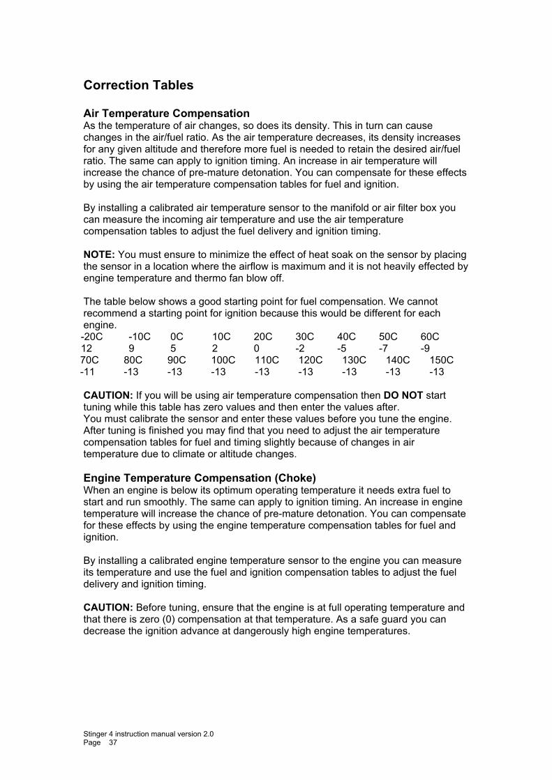
Correction Tables Air Temperature Compensation As the temperature of air changes, so does its density. This in turn can cause changes in the air/fuel ratio. As the air temperature decreases, its density increases for any given altitude and therefore more fuel is needed to retain the desired air/fuel ratio. The same can apply to ignition timing. An increase in air temperature will increase the chance of pre-mature detonation. You can compensate for these effects by using the air temperature compensation tables for fuel and ignition. By installing a calibrated air temperature sensor to the manifold or air filter box you can measure the incoming air temperature and use the air temperature compensation tables to adjust the fuel delivery and ignition timing. NOTE: You must ensure to minimize the effect of heat soak on the sensor by placing the sensor in a location where the airflow is maximum and it is not heavily effected by engine temperature and thermo fan blow off. The table below shows a good starting point for fuel compensation. We cannot recommend a starting point for ignition because this would be different for each engine. -20C -10C 0C 10C 20C 30C 40C 50C 60C 12 9 5 2 0 -2 -5 -7 -9 70C 80C 90C 100C 110C 120C 130C 140C 150C -11 -13 -13 -13 -13 -13 -13 -13 -13 CAUTION: If you will be using air temperature compensation then DO NOT start tuning while this table has zero values and then enter the values after. You must calibrate the sensor and enter these values before you tune the engine. After tuning is finished you may find that you need to adjust the air temperature compensation tables for fuel and timing slightly because of changes in air temperature due to climate or altitude changes. Engine Temperature Compensation (Choke) When an engine is below its optimum operating temperature it needs extra fuel to start and run smoothly. The same can apply to ignition timing. An increase in engine temperature will increase the chance of pre-mature detonation. You can compensate for these effects by using the engine temperature compensation tables for fuel and ignition. By installing a calibrated engine temperature sensor to the engine you can measure its temperature and use the fuel and ignition compensation tables to adjust the fuel delivery and ignition timing. CAUTION: Before tuning, ensure that the engine is at full operating temperature and that there is zero (0) compensation at that temperature. As a safe guard you can decrease the ignition advance at dangerously high engine temperatures.
Stinger 4 instruction manual version 2.0 Page 37

NOTE 1: Both air and water compensation tables adjust the fuel delivery and ignition timing by the percentage entered for a particular temperature. A positive number will increase the fuel or timing by the specified percentage and a negative number will decrease the fuel or timing by the specified percentage. NOTE 2: The values entered in these tables represent the compensation factor when the temperature matches the column heading. For temperatures in between column headings the ECU will apply an interpolation formula to obtain an exact compensation factor. NOTE 3: If either air or engine temperature sensors are not connected then the values in the relevant tables must be set to zero (0).
Stinger 4 instruction manual version 2.0 Page 38
Post/Cold Start Enrichment The Post start enrichment table ensures the engine will start easily by allowing you to increase the amount of fuel for a specified duration after engine start. The increased percentage of fuel will be injected during cranking and decay down to zero percent over a specified time period after the engine starts. When an engine is cold, extra fuel above the choke level is sometimes required for a short period to overcome fuel sticking onto the cold engine parts such as manifold and valves. Also, especially on hot days an engine may experience starting difficulties when trying to start after being stopped for a short time. This is caused when the fuel inside the fuel lines near a hot engine increase in temperature from heat soak. This effect causes the engine to run lean until the cool fuel reaches the injectors. To overcome this problem you can use the Post Start table. All STINGER 4 ECUs allow you to specify a percentage of fuel increase at different engine temperatures over specific time duration. Using the Post Start grid under each temperature column to specify the increase fuel percentage and decay duration in seconds. The system will then apply the specified increase to the fuel delivery and gradually decay it over the duration period. Fuel MAP Override The ECU uses the values in this table internally to calculate a variable resolution fuel map. This enables the tuner to have very fine fuel adjustment over the entire fuel delivery table. Normally, you would not need to adjust these settings except in special situations. Enter the increase or decrease percentage of fuel for each load position on the grid. This percentage change is based on the fuel delivery table. If these values have been removed or changed to the point where the engine is not operating correctly you can easily bring them back to the factory setting by entering the same value as the actual column heading at each point. eg; at the -50 KPA column heading enter -50
At the -20 KPA column heading enter –20 At the 0 KPA column heading enter 0 AT the 25 KPA column heading enter 25 AT the 50 KPA column heading enter 50.
You must do this for each grid position.
Stinger 4 instruction manual version 2.0 Page 39
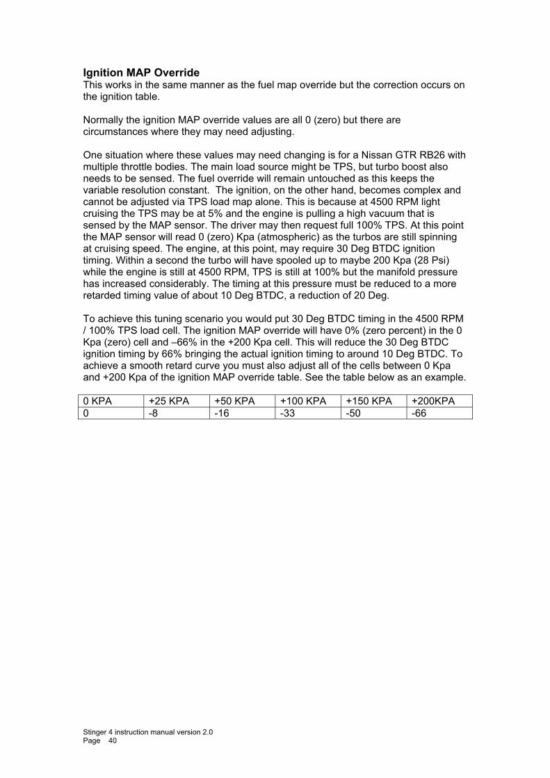
Ignition MAP Override This works in the same manner as the fuel map override but the correction occurs on the ignition table. Normally the ignition MAP override values are all 0 (zero) but there are circumstances where they may need adjusting. One situation where these values may need changing is for a Nissan GTR RB26 with multiple throttle bodies. The main load source might be TPS, but turbo boost also needs to be sensed. The fuel override will remain untouched as this keeps the variable resolution constant. The ignition, on the other hand, becomes complex and cannot be adjusted via TPS load map alone. This is because at 4500 RPM light cruising the TPS may be at 5% and the engine is pulling a high vacuum that is sensed by the MAP sensor. The driver may then request full 100% TPS. At this point the MAP sensor will read 0 (zero) Kpa (atmospheric) as the turbos are still spinning at cruising speed. The engine, at this point, may require 30 Deg BTDC ignition timing. Within a second the turbo will have spooled up to maybe 200 Kpa (28 Psi) while the engine is still at 4500 RPM, TPS is still at 100% but the manifold pressure has increased considerably. The timing at this pressure must be reduced to a more retarded timing value of about 10 Deg BTDC, a reduction of 20 Deg. To achieve this tuning scenario you would put 30 Deg BTDC timing in the 4500 RPM / 100% TPS load cell. The ignition MAP override will have 0% (zero percent) in the 0 Kpa (zero) cell and –66% in the +200 Kpa cell. This will reduce the 30 Deg BTDC ignition timing by 66% bringing the actual ignition timing to around 10 Deg BTDC. To achieve a smooth retard curve you must also adjust all of the cells between 0 Kpa and +200 Kpa of the ignition MAP override table. See the table below as an example. 0 KPA +25 KPA +50 KPA +100 KPA +150 KPA +200KPA 0 -8 -16 -33 -50 -66
Stinger 4 instruction manual version 2.0 Page 40
Other Correction trims and adjustments The section below describes other trims and adjustments that are not tables. Fuel Trim Percentage This parameter applies an increase or decrease percentage on the entire fuel delivery table. This is useful when you need to change the fuel table and still leave the engine-breathing curve unchanged. When you are happy with the performance you can leave the trim value or apply the trim percentage directly to the fuel map by pressing the Re-Adjust Map button beside the Fuel Trim selector. This will adjust the map by the trim percentage and then zero the fuel trim value. Ignition Trim Percentage This feature behaves in the same way as the fuel trim parameter but on the ignition map. It applies an increase or decrease percentage on the entire ignition table. It is useful when you need to change the ignition table and still leave the timing curve unchanged. When you are happy with the performance you can leave the trim value or apply the trim percentage directly to the ignition table by pressing the Re-Adjust Map button beside the Ignition Trim selector. This will adjust the map by the trim percentage and then zero the ignition trim value. Injector Scale The injector scale is used to set the resolution of each increment in the main fuel map. It must be set before tuning the engine. The max injector on time is determined by this value. For example: setting this parameter to 40 will give a maximum injector on time of 20 milliseconds at 0 Kpa (zero). Each load point allows for 255 increments therefore this will allow you to divide 20 milliseconds into 255 increments. Larger injectors would require less milliseconds of on duration to supply the same volume of fuel as smaller injectors. Using this parameter allows the tuner to adjust the fuel map resolution to give a very fine adjustment per increment. Note: As a guide, the injector time scale should be set between 40 and 80. If you find that you need to go above or bellow this range you may need to change injector size or there is a problem in the fuel delivery system.
Stinger 4 instruction manual version 2.0 Page 41
Static Ignition Timing Use this parameter to tell the ECU where the physical location of the trigger sensor is in relation to TDC. If the trigger sensor is 10 degrees BTDC then set this parameter to 10 deg BTDC. The ECU will use this value to calculate the exact ignition timing. To ensure that the static timing is correct you may check it with a timing light. Follow the procedure set out below to check the timing with a timing light. Set the Static Timing parameter to “Locked”. You should hear the engine change note as the timing retards to static. Using a timing light, check the timing and record this value in the Static Timing parameter. Remember to press enter to save the changes to the ECU memory. Staged Injection The STINGER 4 ECUs will allow you to install 1 secondary set of injectors that can be staged to progressively start when the injector capacity reaches over 80 percent duty. For engine configurations where the primary and secondary injectors are the same size, set the staged number to 57.6%. This will cause the injector on-time duty to be halved once the staged injectors are activated. For secondary injectors of a differing size to the primary injectors you will need to adjust this parameter experimentally. If the secondary injectors are smaller than the primary injectors then the number should be larger than 57.6%, thus the ECU will not reduce the injection time as much when the secondary injectors are activated. If the secondary injectors are larger than the primary injectors then the number should be smaller than 57.6%, thus the ECU will reduce the injection time by a larger amount when the secondary injectors are activated. WARNING!! DO NOT SELECT STAGED INJECTION FOR NON-STAGED INJECTED ENGINES, AS THIS WILL CAUSE ENGINE DAMAGE.
Stinger 4 instruction manual version 2.0 Page 42
Launch Control (Turbo Anti-lag) All STINGER 4 ECUs offer 2 launch control modes. One for drag racing and one for rally racing. Note: Anti lag can be disabled via any digital input.
Rally Mode Rally mode is designed for when the car is moving and approaching a curve. At this point the antilag function should be activated in order to keep the turbo spinning while the car is negotiating the curve. This will ensure minimal turbo lag when accelerating out of the corner. When the throttle position signal is BELOW the pre-set TPS level AND the engines RPM is above the pre-set RPM level, the antilag function will be enabled causing the ECU misfire the Ignition in one of 3 fire patterns. The ignition timing and fuel delivery will also be adjusted according to the selected fuel and ignition trim percentages. This feature would be used in conjunction with an auxiliary o/p to energize a blow off solenoid valve to either bypass the throttle body, hold it open slightly or to blow air directly into the exhaust manifold near the exhaust ports.
Stinger 4 instruction manual version 2.0 Page 43
Drag Mode Drag mode is designed for drag racing where the engine is free revving while waiting for the signal to launch. At this point the engine does not have enough load to allow the turbo to produce full boost. Using this function will enable the turbo to produce extra boost. When the throttle signal level is ABOVE the pre-set TPS setting AND the engines RPM is ABOVE the pre-set RPM setting AND the boost pressure is below the pre-set Kpa setting the antilag function will be enabled causing the ECU to misfire the ignition in one of 3 patterns. The ignition timing and fuel delivery will also be adjusted according to the selected fuel and ignition trim percentages. Setting the boost pressure (Turn OFF Above KPA parameter) is the most critical parameter. This also requires very good driver control because the boost is maintained via the amount of throttle opening. If you would like to launch at 50 Kpa (7Psi) of boost, you would set the Turn OFF Above KPA parameter slightly above 50 Kpa, maybe to 55 Kpa. While in gear, the driver holds the clutch down and revs the engine. Once the engine reaches above the Turn On above RPM parameter and the TPS reaches above the Turn On Above TPS parameter then Antilag will activate causing the boost to build up. By pressing the throttle to correct amount, the drive can maintain boost at the launch level. To launch the car the driver will release the clutch and open the throttle fully. At this point the boost will shoot up above the Turn Off Above KPA parameter causing the antilag to deactivate and allow the boost to build up to the higher preset wastegate level. Caution: There is a chance of blowing the engine if the driver presses the throttle too far while free-revving the engine allowing the boost to build up above the Turn Off Above KPA parameter. This may cause the engine to over rev. EMS recommends that you use one of the digital inputs connected to a clutch switch to deactivate the antilag system and set the Turn OFF Above KPA parameter to its maximum value. This method will prevent the engine from over revving while the clutch is disengaged. FUEL TRIM percentage If this parameter is used then the setting should be a positive value (+) to increase the amount of fuel when the antilag function is active. This is normally set between 0 and +3%. IGN TRIM percentage This setting should be a negative value (-) to retard the ignition timing as far as possible. This is normally set to –100%. NOTE:
1. The misfire patterns have been designed to prevent the spark plugs from fowling up.
2. You cannot retard the ignition beyond the static timing value so try and set the static timing as low as possible.
Stinger 4 instruction manual version 2.0 Page 44
Digital Input All STINGER 4 ECUs has 1 digital input that can be used for Antilag (Launch Control), NOS Control, Idle increase, 2-step rev limit or air conditioner control.
Reverse Acting Input activation will be determined by the reverse acting parameter. If set to “normal” then the input will be active when it is grounded. If set to “reverse acting” then the input will be active if its voltage is between 5 and 12 volts.
Disable Anti lag This mode will disable (turn off) the antilag if active. Most common use is to connect to a switch that is actuated by the Clutch pedal or thumb operated switch on the steering wheel. When the pedal or switch is released, the input will be activated thus disabling the anti lag. If you will use this method to disable the antilag then you must set the Turn OFF Above KPA parameter to its maximum value.
Two Step RPM limiter This mode will enable the "Rpm Limit" field. In one switch position, the Ecu will engage the Soft RPM limit to the value selected in the field. In the other switch position, the Ecu reverts back to the normal RPM limits set in the main set-up page. This mode gives the user an extra stall Rpm limit.
Idle Up Percentage (Stall Prevention) This mode is used in conjunction with whichever auxiliary output is set to Idle control. When this mode is selected then the In Gear Idle up % field will become active. The Input can be connected to an auto transmission or air conditioner compressor clutch so that if a gear is selected or the air conditioner cuts in, the idle valve will open by the In Gear idle up % value to help prevent the engine from stalling.
Nos Function This mode is used when Nitros oxide injection is activated. The auxiliary input would be connected to the Nos solenoid. When activated, the user can select the amount of Ignition retard in degrees and fuel enrichment in milliseconds. These two fields will become active when this mode is selected. Note: It is recommended that the fuel portion required with the gas be injected by a separate fuel solenoid and only use the Nos Fuel Increase to trim if a little extra fuel is needed. If you use the Nos Fuel Increase to inject all the fuel required then you must ensure that the fuel injectors are large enough to provide the extra fuel.
Stinger 4 instruction manual version 2.0 Page 45
User defined Gauge Parameters You can define a number of different gauges that can read information from any of the standard information channels such as RPM, Load, TPS, Air/fuel ratio, etc.
Display Type This can be set to "No Display" or one of 4 display types, Digit Gauge, Dial Gauge, Bar Gauge and Scope Gauge. When set to "No Display" then there will be no gauge shown for this channel.
Description This value will be displayed at the top of each gauge. Enter a name that will describe the actual unit being displayed. ie: Exhaust Temp cylinder 1 if this input channel is reading the exhaust temperature of cylinder 1.
Unit of Measure This will also be displayed along with the description. This is an extra description that you can use to enter the unit of measure such as Kpa, Psi, Celsius, etc
Minimum and Maximum These values define the upper and lower limits of the gauge. The gauge will indicate values between these two parameters.
Unit Multiplier This value works with the minimum and maximum values so that the gauge can calculate the correct display value from the actual data value. ie: To define an RPM gauge showing from 0 to 6000 RPM and the numbers on the dial to read 0 to 60 you would set the minimum at 0 and the maximum at 60 and a multiplier value of 100.
Stinger 4 instruction manual version 2.0 Page 46
Number of Digits This will determine the number of digits that will be shown on any of the gauges.
Decimal Places This value determines the accuracy of the display by defining the decimal accuracy.
Number of Labels On a dial or scope gauge this value determines how many increments are used. On a bar gauge it determines the maximum number of bars displayed. For a digital gauge the value has no effect. For best results you should choose a number that can be divided evenly into the maximum parameter value. eg: If you defined a dial gauge to show RPM up to a maximum of 10000 RPM and set the number of labels to 5 then the gauge will evenly divide the labels into 5 increments that show 2000, 4000, 6000, 8000 and 10000.
Green and Blue Zone Percentages Each dial and bar gauge can be shown with three different colour zones, green, blue and red. Use these values to set the green and blue percentages and the remaining percentage will be shown in red.
Show Digit Display If this parameter is ticked then the gauge will also display a textual representation of the gauge value.
Show Colour Zones If you do not want a gauge to show colour zones then simply un-tick this parameter.
Retain Max Value This only works with dial gauges. The gauge will retain the maximum value reached on the gauge. NOTE: The colour zones will not show if this parameter is ticked.
Stinger 4 instruction manual version 2.0 Page 47
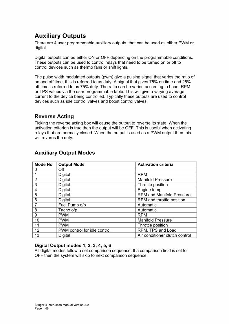
Auxiliary Outputs There are 4 user programmable auxiliary outputs. that can be used as either PWM or digital. Digital outputs can be either ON or OFF depending on the programmable conditions. These outputs can be used to control relays that need to be turned on or off to control devices such as thermo fans or shift lights. The pulse width modulated outputs (pwm) give a pulsing signal that varies the ratio of on and off time, this is referred to as duty. A signal that gives 75% on time and 25% off time is referred to as 75% duty. The ratio can be varied according to Load, RPM or TPS values via the user programmable table. This will give a varying average current to the device being controlled. Typically these outputs are used to control devices such as idle control valves and boost control valves.
Reverse Acting Ticking the reverse acting box will cause the output to reverse its state. When the activation criterion is true then the output will be OFF. This is useful when activating relays that are normally closed. When the output is used as a PWM output then this will reveres the duty.
Auxiliary Output Modes Mode No Output Mode Activation criteria 0 Off 1 Digital RPM 2 Digital Manifold Pressure 3 Digital Throttle position 4 Digital Engine temp 5 Digital RPM and Manifold Pressure 6 Digital RPM and throttle position 7 Fuel Pump o/p Automatic 8 Tacho o/p Automatic 9 PWM RPM 10 PWM Manifold Pressure 11 PWM Throttle position 12 PWM control for idle control. RPM, TPS and Load 13 Digital Air conditioner clutch control Digital Output modes 1, 2, 3, 4, 5, 6 All digital modes follow a set comparison sequence. If a comparison field is set to OFF then the system will skip to next comparison sequence.
Stinger 4 instruction manual version 2.0 Page 48
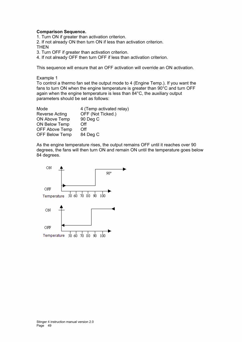
Comparison Sequence. 1. Turn ON if greater than activation criterion. 2. If not already ON then turn ON if less than activation criterion. THEN 3. Turn OFF if greater than activation criterion. 4. If not already OFF then turn OFF if less than activation criterion. This sequence will ensure that an OFF activation will override an ON activation. Example 1 To control a thermo fan set the output mode to 4 (Engine Temp.). If you want the fans to turn ON when the engine temperature is greater than 90°C and turn OFF again when the engine temperature is less than 84°C, the auxiliary output parameters should be set as follows: Mode 4 (Temp activated relay) Reverse Acting OFF (Not Ticked.) ON Above Temp 90 Deg C ON Below Temp Off OFF Above Temp Off OFF Below Temp 84 Deg C As the engine temperature rises, the output remains OFF until it reaches over 90 degrees, the fans will then turn ON and remain ON until the temperature goes below 84 degrees.
Stinger 4 instruction manual version 2.0 Page 49
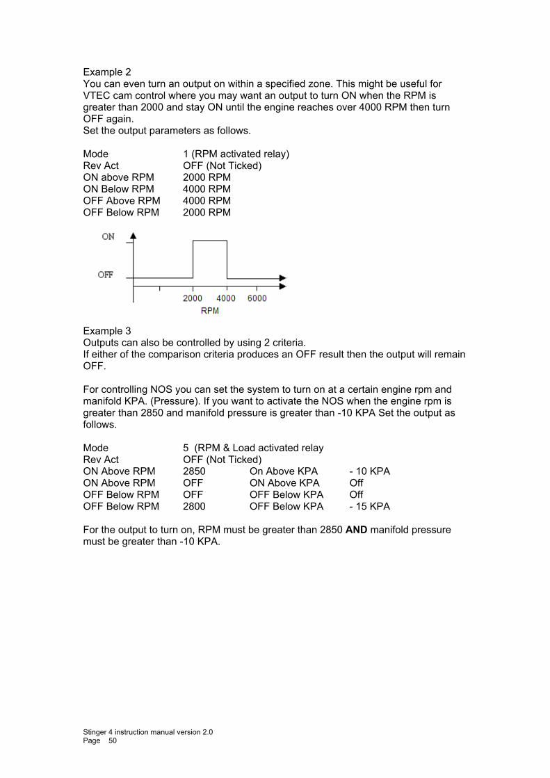
Example 2 You can even turn an output on within a specified zone. This might be useful for VTEC cam control where you may want an output to turn ON when the RPM is greater than 2000 and stay ON until the engine reaches over 4000 RPM then turn OFF again. Set the output parameters as follows. Mode 1 (RPM activated relay) Rev Act OFF (Not Ticked) ON above RPM 2000 RPM ON Below RPM 4000 RPM OFF Above RPM 4000 RPM OFF Below RPM 2000 RPM
Example 3 Outputs can also be controlled by using 2 criteria. If either of the comparison criteria produces an OFF result then the output will remain OFF. For controlling NOS you can set the system to turn on at a certain engine rpm and manifold KPA. (Pressure). If you want to activate the NOS when the engine rpm is greater than 2850 and manifold pressure is greater than -10 KPA Set the output as follows. Mode 5 (RPM & Load activated relay Rev Act OFF (Not Ticked) ON Above RPM 2850 On Above KPA - 10 KPA ON Above RPM OFF ON Above KPA Off OFF Below RPM OFF OFF Below KPA Off OFF Below RPM 2800 OFF Below KPA - 15 KPA For the output to turn on, RPM must be greater than 2850 AND manifold pressure must be greater than -10 KPA.
Stinger 4 instruction manual version 2.0 Page 50

Auxiliary output modes 7 and 8 Fuel Pump Relay Mode 7 The Fuel pump output is designed to drive a fuel pump relay. When the ignition is turned on, the output will energize for approx. 4 seconds and then turn off again. While the ECU detects that the engine is running it will keep the fuel pump on. If the engine stalls or stops, the Ecu will turn the fuel pump off after 4 seconds. This is a safety feature that is required in some motor sports. Tacho Output Mode 8 When this mode is selected the output will produce a signal that is compatible with most tachos. In some cases where the tacho does not have an internal resistor connecting its input to power you will need to connect an external 500 – 1000 ohm resistor from the tacho input to power.
Stinger 4 instruction manual version 2.0 Page 51
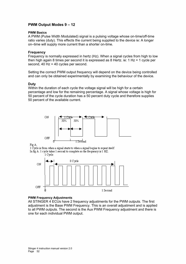
PWM Output Modes 9 – 12 PWM Basics A PWM (Pulse Width Modulated) signal is a pulsing voltage whose on-time/off-time ratio varies (duty). This effects the current being supplied to the device ie: A longer on–time will supply more current than a shorter on-time. Frequency Frequency is normally expressed in hertz (Hz). When a signal cycles from high to low then high again 8 times per second it is expressed as 8 Hertz. ie: 1 Hz = 1 cycle per second, 40 Hz = 40 cycles per second. Setting the correct PWM output frequency will depend on the device being controlled and can only be obtained experimentally by examining the behaviour of the device. Duty Within the duration of each cycle the voltage signal will be high for a certain percentage and low for the remaining percentage. A signal whose voltage is high for 50 percent of the cycle duration has a 50 percent duty cycle and therefore supplies 50 percent of the available current.
PWM Frequency Adjustments All STINGER 4 ECUs have 2 frequency adjustments for the PWM outputs. The first adjustment is the Base PWM Frequency. This is an overall adjustment and is applied to all PWM outputs. The second is the Aux PWM Frequency adjustment and there is one for each individual PWM output.
Stinger 4 instruction manual version 2.0 Page 52
Base PWM Frequency The base frequency is used to calculate the operating frequency of all PWM outputs. Aux PWM Frequency This setting should be set to 255 wherever possible. It determines the pulse frequency of each PWM output according to the following formula. Output frequency = 255 / Aux PWM Frequency * Base PWM Frequency. ie: By setting the Base PWM Frequency to 20 Hz and the Aux PWM Frequency to 200 will result in an output frequency of 25.5 Hz. ( 255 / 200 * 20 = 25.5 ) NOTE: Reducing the Aux PWM Frequency number will increase the frequency for the output but there is a trade off. The duty cycle adjustment resolution of the output will be reduced. ie: If this frequency number is reduced to 100 for example, the output frequency would increase, but the adjustment resolution will be reduced from 255 to 100 increments. Adjusting the Duty Cycle PWM outputs are used to control devices that can vary their state like idle control valves, these devices can be fully closed, fully open or anywhere in between. This is achieved by varying the ratio of on-time and off-time of the output signal. This is referred to as duty cycle. Longer on-time will increase the supply of current therefore opening the valve further. You can vary the duty cycle of a PWM output according to engine RPM, manifold pressure or throttle position by entering the amount of duty in the duty table. The maximum allowed number in this table is determined by the value of the Aux PWM Frequency. ie: if the Aux PWM Frequency is set to 120 then entering 120 in the duty table will result in maximum duty thereby supplying maximum current. A value of 60 will result in 50 percent duty and therefore 50 percent current. Reverse Acting The Reverse Acting function will reverse the duty cycle of the output. This function is needed when a valve works backwards, eg. Bosch BMW idle valve. With these types of valves, increasing the duty cycle will actually slow down the engine and reducing the duty cycle will increase the idle speed.
Stinger 4 instruction manual version 2.0 Page 53
PWM Verses RPM Mode 9 In this mode you can set the PWM duty according to engine RPM in 500 RPM increments. The system will interpolate between RPM points to achieve a smooth transition. For example, you can use this mode to control turbo boost level at 500 RPM increments and the system will provide a smooth transition between RPM points. PWM Verses Kpa Mode 10 In this mode you can set the PWM duty according to manifold pressure in 20 Kpa increments from –100 Kpa to 400 Kpa. The system will interpolate between points to achieve a smooth transition. For example to control a water injection D.C. motor, you can set a low duty value at low manifold pressure and increase it as manifold pressure increases thereby increasing the motor speed and in turn increasing the water injection. PWM Verses Throttle Position Mode 11 In this mode you can set the PWM duty according to throttle position in 5 percent increments from 0 percent to 100 percent. The system will interpolate between points to achieve a smooth transition. For example to control a water injection D.C. motor, you can set a low duty value at small throttle openings and increase it as the throttle increasingly opens thereby increasing the motor speed and in turn increasing the water injection. Closed Loop Idle control The ECU must be sensing manifold pressure via the built-in MAP sensor. I Although idle control sounds simple to achieve, the parameters and mathematics involved are quite complicated. EMS has tried to make it as simple as possible to set-up by providing a simple set-up procedure to follow. Step 1: Ensure the engine is well tuned Ensure that the engine is properly tuned especially in the idle area. The automatic idle control will continually try to adjust a badly tuned engine around the idle RPM Step 2: Select an output circuit to use Now we will need to use the laptop software for these adjustments. Set Idle control to off (this ensures that the valve will be closed) Type in the target idle RPM Set Initial open position to around 20 Set Max Steps to 255 Set idle vacuum to whatever the engine is currently idling on while at operating temp Set Additional Cold Open Position to around 60 These numbers are only starting points and will be adjusted to suit the engine.
Stinger 4 instruction manual version 2.0 Page 54
Step 3: Set the mechanical idle speed adjustment Set the mechanical idle screw until the engine idles 100 RPM lower than the Target RPM. This is a backup to prevent the engine from stalling if the idle control motor or valve fails. Step 4: final adjustment Set Idle Control to Manual Adjust the Initial Open Position (higher or lower) until the engine idles at the Target RPM. Set the Idle control to Automatic. Step 5: Cold engine adjustment Do this the next morning when the engine is fully cold. Before starting the engine set Idle control to Manual. Start the engine and adjust the Additional Cold Open Position only (higher or lower) until the engine idles at the Target RPM. Set the Idle control to Automatic.
Stinger 4 instruction manual version 2.0 Page 55
Air and Engine Temp Sensor Calibration There are many different types of sensors with varying resistances by different manufacturers. This means that a sensor calibration table is needed to translate the output of the sensor being used into a meaningful temperature value. If you do not find a file that gives you the correct temperature readings, you will need to either create your own new calibration or modify an existing file. Some OEM sensors may have + or - 10% variation. In extreme cases, you may decide to recalibrate the file you are using.
Using an existing File EMS provides some pre-defined sensor calibration files. You may download one of these files into your ECU. To use an existing file, press the open calibration button. A dialog box will open showing a list of pre-defined calibration tables. Select the one you want to use and press the open button. This will read the file and display the data in the calibration grid. To download this calibration to the ECU, press the Write to ECU button. Once the progress bar has finished, the calibration has been sent to the ECU. To view the current temperature as seen by the ECU, Go-to the tuning page or press the CTRL+G buttons to display the live gauges screen. If the temperature is not correct, try a different file or modify the table and Write it to the ECU again.
Creating your own File To create a new calibration file for a sensor it must be connected to the ECU so that the ECU can read its signal voltage. You will also need a thermometer that can read the temperature of the sensor being calibrated. An easy way to do this is to place the sensor and thermometer in a tub of hot water. This will ensure that the thermometer is showing the temperature of the sensor. As the water cools down the sensor signal voltage will change giving a different A/D value for different temperatures. NOTE: All numbers in the table MUST be in ascending or descending order. Calibration Steps This example describes how to calibrate a sensor using the method mentioned above. If you need to calibrate a sensor for temperatures that are beyond the scope of this method you will need to devise your own calibration method. Calibration must be done while the sensor is connected to the ECU.
Stinger 4 instruction manual version 2.0 Page 56
Heat a tub of water to 100 deg C (boiling), place the sensor and thermometer in the water and allow it to cool down to room temperature. If you want to go below room temperature then you can add ice to the water after room temperature is reached. While it is cooling you will read the A/D value at each temperature interval.
1. Click on the 100 Deg C column of the calibration table. 2. Wait until the thermometer reads 100 Deg C 3. Press the Accept Reading Button to write the A/D value into the table. 4. Click on the 90 Deg C column of the calibration table. 5. Wait until the thermometer reads 90 Deg C. 6. Press the Accept Reading Button again to write the A/D value into the table. 7. Repeat this pattern until you have calibrated the desired temperature range.
If you could not obtain a reading for every temperature column then you can make an educated guess as to what the A/D value should be for the un-calibrated columns by studying the number pattern of the calibrated columns. ie: If you see that the A/D number increases by 100 for every 10 degrees in temperature increase then you could guess that the A/D value at 110 Deg should be 100 greater than the value at 100 Deg. You can then type this number in the 110 deg column. Press the Save Calibration File button to save your new calibration table. A dialog box will appear allowing you to enter a file name before you press the Save button. If a calibration table with the same name already exists then it will be over-written. You can also download the new table to the ECU by pressing the Write to ECU button. To see the current A/D value without writing it to the table press the Read A to D Button.
Stinger 4 instruction manual version 2.0 Page 57
Data Logging The data-logging feature of the software allows you to log up to 21 individual parameters to a laptop at a rate of 10 lines per second. You can control when data logging starts and stops by setting the RPM start and stop parameters and the duration parameters.
Start/Stop (F2) logging Set the “Start logging when RPM is greater than” parameter to the desired RPM start point. Set the “Stop logging when RPM is less than” parameter to the desired RPM stop point. You must also set the duration for which these parameters must be met. When you press the “Start Logging” button (or F2 key) the system will wait for the RPM to reach the desired start point for the specified duration and then commence logging the data. When the RPM falls to the desired stop point for the specified duration the system will stop logging and also save the data to disk with the file name “Last Log.el3”. This file will always be overridden whenever the system automatically saves the logged data. You can also manually save the data with a different file name when you go back to the pits. Each time the RPM falls below the stop point five blank data log lines will be recorded. This will make it easier to see each time the logging started and stopped during a log session. To stop the logging session completely, press the same button used to start the session or press the F2 key. This time the button will be named “Stop logging” to indicate that pressing it will stop the session.
Viewing the logged data To view the data you must stop the logging session by pressing the “Stop Logging” button, this is the same as the “Start Logging” button (or F2 key). The laptop may take a few minutes to organize the data before it is displayed on the main page in text format. This data can be scrolled through with the arrow buttons and analysed. The data is organised with the last log record being at the top and the first at the bottom of the grid. Each line represents a reading of 21 parameters. The first parameter shows the Reading number. The second shows the Time stamp, followed by the engine parameters sent by the. All standard engine parameter values will be shown as actual technical values such as RPM, Engine temperature in degrees Celsius, etc. You can also view the data in chart form. Pressing the “Log Chart” button displays the data log session in graphical form. The system displays data onto four separate chart axis. Each axis can display data from any of the standard ECU engine parameters. You can select the data for each axis by using the drop-down selection field for each axis and selecting the data channel you want to display.
Zooming into a section of the chart You can zoom into a chart section by pressing the left mouse button and dragging a square from top left corner to bottom right corner covering the section you want to zoom into. When you release the mouse button the button chart will zoom into the selected area. To un-zoom you just reverse the process.
Stinger 4 instruction manual version 2.0 Page 58
Stinger 4 instruction manual version 2.0 Page 59
Printing a log chart You can print the log chart to any printer connected to you PC. To print a chart, press the print button that is just above the chart, select the appropriate print options such as printer, margines, page orientation, etc and then press the “Print” Button. You can also print a zoomed section of the chart by zooming into the area you want printed before you press the print button.
Saving a log chart Saving a log chart is not the same as saving the log data. The chart will be saved as graphics file that can be used by a graphics programme such as MS Paint. To save a log chart press the save button located just above the chart. When the save dialog screen appears, select “Bitmaps (*.Bmp)” in the “Save as type” selection field, Type in an appropriate name for the chart and then press the “Save” button.
Copying a log chart to the clipboard You can copy a chart to the clipboard by pressing the copy button located above the chart. Doing this will copy an image of the chart to the clipboard, you can then paste it into another application such as Excel, Word, Paint, Etc.
Saving the logged data You can save the entire log session so you can view the information at any time in the future. To save the session, select “Save File” from the File menu. When the save dialog screen appears type in a file name in the “File Name” field and press the “Save” button. If you want to overwrite an existing file then select it from the list of previously saved files.
Opening an existing data-log file To open a previously saved log session, select “Open File” from the File menu. When the open dialog screen appears select the file you want to view from the list of previously saved log sessions and press the “Open” button.
Exporting the logged data You can export data into either an Excel data file or a tab delimited text file. To export the logged data, select “Export Data” from the file menu. When the export dialog screen appears then select either Excel or text, select or type in a file name and then press the “Start Export” button. When the export has finished the exported data will be displayed in the selected file format. If Excel was selected then the system will open the Excel application with the exported data. If you do not want the exported data to be displayed then un-tick the “Open file after export” option located just beneath “Destination File” field.
Related Documents