Dynamic Multipoint VPN The Dynamic Multipoint VPN (DMVPN) feature allows users to better scale large and small IP Security (IPsec) Virtual Private Networks (VPNs) by combining generic routing encapsulation (GRE) tunnels, IPsec encryption, and Next Hop Resolution Protocol (NHRP). Security threats, as well as the cryptographic technologies to help protect against them, are constantly changing. For more information about the latest Cisco cryptographic recommendations, see the Next Generation Encryption (NGE) white paper. Note • Finding Feature Information, page 1 • Prerequisites for Dynamic Multipoint VPN (DMVPN), page 2 • Restrictions for Dynamic Multipoint VPN (DMVPN), page 2 • Information About Dynamic Multipoint VPN (DMVPN), page 4 • How to Configure Dynamic Multipoint VPN (DMVPN), page 11 • Configuration Examples for Dynamic Multipoint VPN (DMVPN) Feature, page 32 • Additional References, page 46 • Feature Information for Dynamic Multipoint VPN (DMVPN), page 48 • Glossary, page 50 Finding Feature Information Your software release may not support all the features documented in this module. For the latest caveats and feature information, see Bug Search Tool and the release notes for your platform and software release. To find information about the features documented in this module, and to see a list of the releases in which each feature is supported, see the feature information table. Use Cisco Feature Navigator to find information about platform support and Cisco software image support. To access Cisco Feature Navigator, go to www.cisco.com/go/cfn. An account on Cisco.com is not required. Dynamic Multipoint VPN Configuration Guide, Cisco IOS Release 15M&T 1

Welcome message from author
This document is posted to help you gain knowledge. Please leave a comment to let me know what you think about it! Share it to your friends and learn new things together.
Transcript
Dynamic Multipoint VPN
The Dynamic Multipoint VPN (DMVPN) feature allows users to better scale large and small IP Security(IPsec) Virtual Private Networks (VPNs) by combining generic routing encapsulation (GRE) tunnels, IPsecencryption, and Next Hop Resolution Protocol (NHRP).
Security threats, as well as the cryptographic technologies to help protect against them, are constantlychanging. For more information about the latest Cisco cryptographic recommendations, see the NextGeneration Encryption (NGE) white paper.
Note
• Finding Feature Information, page 1
• Prerequisites for Dynamic Multipoint VPN (DMVPN), page 2
• Restrictions for Dynamic Multipoint VPN (DMVPN), page 2
• Information About Dynamic Multipoint VPN (DMVPN), page 4
• How to Configure Dynamic Multipoint VPN (DMVPN), page 11
• Configuration Examples for Dynamic Multipoint VPN (DMVPN) Feature, page 32
• Additional References, page 46
• Feature Information for Dynamic Multipoint VPN (DMVPN), page 48
• Glossary, page 50
Finding Feature InformationYour software release may not support all the features documented in this module. For the latest caveats andfeature information, see Bug Search Tool and the release notes for your platform and software release. Tofind information about the features documented in this module, and to see a list of the releases in which eachfeature is supported, see the feature information table.
Use Cisco Feature Navigator to find information about platform support and Cisco software image support.To access Cisco Feature Navigator, go to www.cisco.com/go/cfn. An account on Cisco.com is not required.
Dynamic Multipoint VPN Configuration Guide, Cisco IOS Release 15M&T 1
Prerequisites for Dynamic Multipoint VPN (DMVPN)• Before a multipoint GRE (mGRE) and IPsec tunnel can be established, you must define an Internet KeyExchange (IKE) policy by using the crypto isakmp policy command.
• For the NAT-Transparency Aware enhancement to work, you must use IPsec transport mode on thetransform set. Also, even though NAT-Transparency can support two peers (IKE and IPsec) beingtranslated to the same IP address (using the User Datagram Protocol [UDP] ports to differentiate them[that is, Peer Address Translation (PAT)]), this functionality is not supported for DMVPN. All DMVPNspokes must have a unique IP address after they have been NAT translated. They can have the same IPaddress before they are NAT translated.
• To enable 2547oDMPVN--Traffic Segmentation Within DMVPN you must configure multiprotocollabel switching (MPLS) by using thempls ip command.
Restrictions for Dynamic Multipoint VPN (DMVPN)• If you use the Dynamic Creation for Spoke-to-Spoke Tunnels benefit of this feature, you must use IKEcertificates or wildcard preshared keys for Internet Security Association Key Management Protocol(ISAKMP) authentication.
It is highly recommended that you do not use wildcard preshared keys because the attacker will haveaccess to the VPN if one spoke router is compromised.
Note
• GRE tunnel keepalives (that is, the keepalive command under a GRE interface) are not supported onpoint-to-point or multipoint GRE tunnels in a DMVPN Network.
• For best DMVPN functionality, it is recommended that you run the latest Cisco IOS software Release12.4 mainline,12.4T, or 12.2(18)SXF.
• If one spoke is behind one NAT device and another different spoke is behind another NAT device, andPeer Address Translation (PAT) is the type of NAT used on both NAT devices, then a session initiatedbetween the two spokes cannot be established.
One example of a PAT configuration on a NAT interface is:
ip nat inside source list nat_acl interface FastEthernet0/1 overload
DMVPN Support on the Cisco 6500 and Cisco 7600
Blade-to-Blade Switchover on the Cisco 6500 and Cisco 7600
• DMVPN does not support blade-to-blade switchover on the Cisco 6500 and Cisco 7600.
Dynamic Multipoint VPN Configuration Guide, Cisco IOS Release 15M&T2
Dynamic Multipoint VPNPrerequisites for Dynamic Multipoint VPN (DMVPN)
Cisco 6500 or Cisco 7600 As a DMVPN Hub
• A Cisco 6500 or Cisco 7600 that is functioning as a DMVPN hub cannot be located behind a NATrouter.
• If a Cisco 6500 or Cisco 7600 is functioning as a DMVPN hub, the spoke behind NAT must be a Cisco6500 or Cisco 7600, respectively, or the router must be upgraded to Cisco IOS software Release12.3(11)T02 or a later release.
Cisco 6500 or Cisco 7600 As a DMVPN Spoke
• If a Cisco 6500 or Cisco 7600 is functioning as a spoke, the hub cannot be behind NAT.
• If a Cisco 6500 or Cisco 7600 is functioning as a DMVPN spoke behind NAT, the hub must be a Cisco6500 or Cisco 7600, respectively, or the router must be upgraded to Cisco IOS Release 12.3(11)T02 ora later release.
DMVPN Hub or Spoke Supervisor Engine
• Only a Supervisor Engine 720 can be used as a DMVPN hub or spoke. A Supervisor Engine 2 cannotbe used.
Encrypted Multicast with GRE
• Encrypted Multicast with GRE is not supported on the Cisco 6500 nor on the Cisco 7600.
mGRE Interfaces
• If there are two mGRE interfaces on the same DMVPN node and they both do not have a tunnel key,the two mGRE interfaces must each have a unique tunnel source address (or interface) configured.
• On the Cisco 6500 and Cisco 7600, each GRE interface (multipoint or point-to-point) must have a uniquetunnel source address (or interface).
• The following commands are not supported under mGRE with DMVPN: ip tcp adjust-mss, qospre-classify tunnel vrf, tunnel path-mtu-discovery, and tunnel vrf.
Quality of Service (QoS)
• You cannot use QoS for DMVPN packets on a Cisco 6500 or Cisco 7600.
Tunnel Key
• The use of a tunnel key on a GRE (multipoint or point-to-point) interface is not supported in the hardwareswitching ASICs on the Cisco 6500 and Cisco 7600 platforms. If a tunnel key is configured, throughputperformance is greatly reduced.
• In Cisco IOS Release 12.3(11)T3 and Release 12.3(14)T, the requirement that a mGRE interface musthave a tunnel key was removed. Therefore, in a DMVPN network that includes a Cisco 6500 or Cisco7600 as a DMVPN node, you should remove the tunnel key from all DMVPN nodes in the DMVPNnetwork, thus preserving the throughput performance on the Cisco 6500 and Cisco 7600 platforms.
Dynamic Multipoint VPN Configuration Guide, Cisco IOS Release 15M&T 3
Dynamic Multipoint VPNDMVPN Support on the Cisco 6500 and Cisco 7600
• If the tunnel key is not configured on any DMVPN node within a DMVPN network, it must not beconfigured on all DMVPN nodes with the DMVPN network.
VRF-Aware DMVPN Scenarios
• Themls mpls tunnel-recircommand must be configured on the provider equipment (PE) DMVPN hubif customer equipment (CE) DMVPN spokes need to “talk” to other CEs across the MPLS cloud.
• The mGRE interface should be configured with a large enough IP maximum transmission unit (1400packets to avoid having the route processor doing fragmentation.
• Enhanced Interior Gateway Routing Protocol (EIGRP) should be avoided.
Information About Dynamic Multipoint VPN (DMVPN)
Benefits of Dynamic Multipoint VPN (DMVPN)
Hub Router Configuration Reduction
• Currently, for each spoke router, there is a separate block of configuration lines on the hub router thatdefine the crypto map characteristics, the crypto access list, and the GRE tunnel interface. This featureallows users to configure a single mGRE tunnel interface, a single IPsec profile, and no crypto accesslists on the hub router to handle all spoke routers. Thus, the size of the configuration on the hub routerremains constant even if spoke routers are added to the network.
• DMVPN architecture can group many spokes into a single multipoint GRE interface, removing the needfor a distinct physical or logical interface for each spoke in a native IPsec installation.
Automatic IPsec Encryption Initiation
• GRE has the peer source and destination address configured or resolved with NHRP. Thus, this featureallows IPsec to be immediately triggered for the point-to-point GRE tunneling or when the GRE peeraddress is resolved via NHRP for the multipoint GRE tunnel.
Support for Dynamically Addressed Spoke Routers
• When using point-to-point GRE and IPsec hub-and-spoke VPN networks, the physical interface IPaddress of the spoke routers must be known when configuring the hub router because IP address mustbe configured as the GRE tunnel destination address. This feature allows spoke routers to have dynamicphysical interface IP addresses (common for cable and DSL connections). When the spoke router comesonline, it will send registration packets to the hub router: within these registration packets, is the currentphysical interface IP address of this spoke.
Dynamic Creation for Spoke-to-Spoke Tunnels
• This feature eliminates the need for spoke-to-spoke configuration for direct tunnels. When a spoke routerwants to transmit a packet to another spoke router, it can now use NHRP to dynamically determine therequired destination address of the target spoke router. (The hub router acts as the NHRP server, handling
Dynamic Multipoint VPN Configuration Guide, Cisco IOS Release 15M&T4
Dynamic Multipoint VPNInformation About Dynamic Multipoint VPN (DMVPN)
the request for the source spoke router.) The two spoke routers dynamically create an IPsec tunnelbetween them so data can be directly transferred.
VRF Integrated DMVPN
• DMVPNs can be used to extend the Multiprotocol Label Switching (MPLS) networks that are deployedby service providers to take advantage of the ease of configuration of hub and spokes, to provide supportfor dynamically addressed customer premises equipment (CPEs), and to provide zero-touch provisioningfor adding new spokes into a DMVPN.
Feature Design of Dynamic Multipoint VPN (DMVPN)TheDynamicMultipoint VPN (DMVPN) feature combines GRE tunnels, IPsec encryption, and NHRP routingto provide users an ease of configuration via crypto profiles--which override the requirement for definingstatic crypto maps--and dynamic discovery of tunnel endpoints.
This feature relies on the following two Cisco enhanced standard technologies:
• NHRP--A client and server protocol where the hub is the server and the spokes are the clients. The hubmaintains an NHRP database of the public interface addresses of the each spoke. Each spoke registersits real address when it boots and queries the NHRP database for real addresses of the destination spokesto build direct tunnels.
• mGRETunnel Interface --Allows a single GRE interface to support multiple IPsec tunnels and simplifiesthe size and complexity of the configuration.
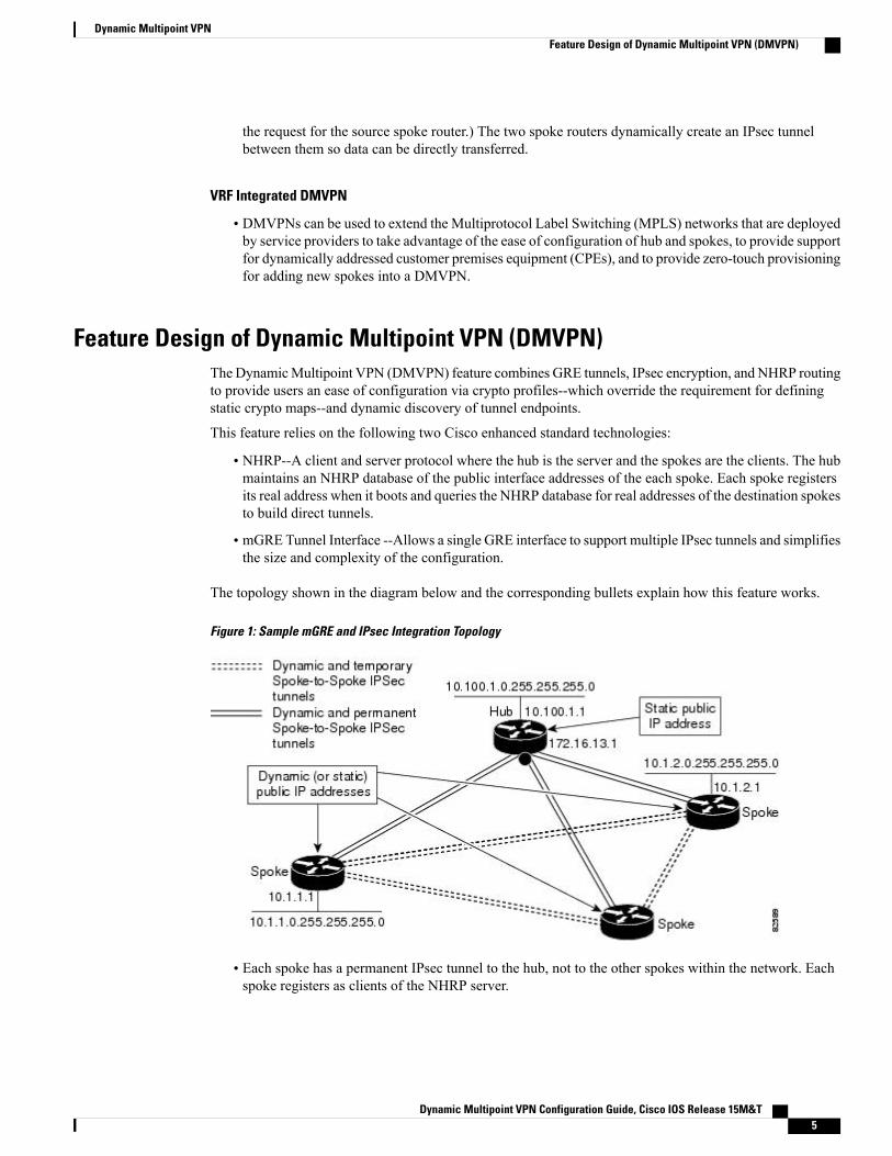
The topology shown in the diagram below and the corresponding bullets explain how this feature works.
Figure 1: Sample mGRE and IPsec Integration Topology
• Each spoke has a permanent IPsec tunnel to the hub, not to the other spokes within the network. Eachspoke registers as clients of the NHRP server.
Dynamic Multipoint VPN Configuration Guide, Cisco IOS Release 15M&T 5
Dynamic Multipoint VPNFeature Design of Dynamic Multipoint VPN (DMVPN)
• When a spoke needs to send a packet to a destination (private) subnet on another spoke, it queries theNHRP server for the real (outside) address of the destination (target) spoke.
• After the originating spoke “learns” the peer address of the target spoke, it can initiate a dynamic IPsectunnel to the target spoke.
• The spoke-to-spoke tunnel is built over the multipoint GRE interface.
• The spoke-to-spoke links are established on demand whenever there is traffic between the spokes.Thereafter, packets can bypass the hub and use the spoke-to-spoke tunnel.
After a preconfigured amount of inactivity on the spoke-to-spoke tunnels, the router will tear down thosetunnels to save resources (IPsec security associations [SAs]).
Note
IPsec ProfilesIPsec profiles abstract IPsec policy information into a single configuration entity, which can be referencedby name from other parts of the configuration. Therefore, users can configure functionality such as GREtunnel protection with a single line of configuration. By referencing an IPsec profile, the user does not haveto configure an entire crypto map configuration. An IPsec profile contains only IPsec information; that is, itdoes not contain any access list information or peering information.
VRF Integrated DMVPNVPNRouting and Forwarding (VRF) Integrated DMVPN enables users to mapDMVPNmultipoint interfacesinto MPLS VPNs. This mapping allows Internet service providers (ISPs) to extend their existing MPLS VPNservices by mapping off-network sites (typically a branch office) to their respective MPLS VPNs. Customerequipment (CE) routers are terminated on the DMVPN PE router, and traffic is placed in the VRF instanceof an MPLS VPN.
DMVPN can interact with MPLS VPNs in two ways:
1 The ip vrf forwarding command is used to inject the data IP packets (those packets inside themGRE+IPsectunnel) into the MPLS VPN. The ip vrf forwarding command is supported for DMVPN in Cisco IOSRelease 12.3(6) and Release 12.3(7)T.
2 The tunnel vrf command is used to transport (route) the mGRE+IPsec tunnel packet itself within anMPLSVPN. The tunnel vrf command is supported in Cisco IOS Release 12.3(11)T but not in Cisco IOS Release12.2(18)SXE.
Clear-text data IP packets are forwarded in a VRF using the ip vrf forwarding command, and encryptedtunnel IP packets are forwarded in a VRF using the tunnel vrf command.
Note
The ip vrf forwarding and tunnel vrf commands may be used at the same time. If they are used at the sametime, the VRF name of each command may be the same or different.
For information about configuring the forwarding of clear-text data IP packets into a VRF, see the section“Configuring the Forwarding of Clear-Text Data IP Packets into a VRF.” For information about configuring
Dynamic Multipoint VPN Configuration Guide, Cisco IOS Release 15M&T6
Dynamic Multipoint VPNIPsec Profiles
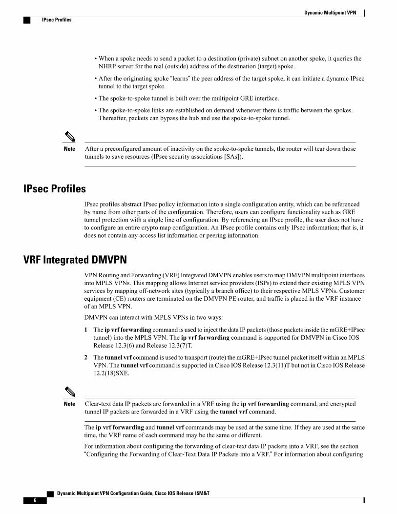
the forwarding of encrypted tunnel packets into a VRF, see the section “Configuring the Forwarding ofEncrypted Tunnel Packets into a VRF.”For more information about configuring VRF, see reference in the “Related Documents” section.The diagram below illustrates a typical VRF Integrated DMVPN scenario.
Figure 2: VRF Integrated DMVPN
DMVPN--Enabling Traffic Segmentation Within DMVPNCisco IOS Release 12.4(11)T provides an enhancement that allows you to segment VPN traffic within aDMVPN tunnel. VRF instances are labeled, using MPLS, to indicate their source and destination.
Dynamic Multipoint VPN Configuration Guide, Cisco IOS Release 15M&T 7
Dynamic Multipoint VPNDMVPN--Enabling Traffic Segmentation Within DMVPN
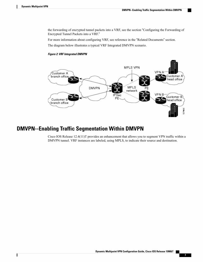
The diagram below and the corresponding bullets explain how traffic segmentation within DMVPN works.
Figure 3: Traffic Segmentation with DMVPN
• The hub shown in the diagram is aWAN-PE and a route reflector, and the spokes (PE routers) are clients.
• There are three VRFs, designated “red,” “green,” and “blue.”
• Each spoke has both a neighbor relationship with the hub (multiprotocol Border Gateway Protocol[MP-iBGP] peering) and a GRE tunnel to the hub.
• Each spoke advertises its routes and VPNv4 prefixes to the hub.
• The hub sets its own IP address as the next-hop route for all the VPNv4 addresses it learns from thespokes and assigns a local MPLS label for each VPN when it advertises routes back to the spokes. Asa result, traffic from Spoke A to Spoke B is routed via the hub.
An example illustrates the process:
1 Spoke A advertises a VPNv4 route to the hub, and applies the label X to the VPN.
2 The hub changes the label to Y when the hub advertises the route to Spoke B.
3 When Spoke B has traffic to send to Spoke A, it applies the Y label, and the traffic goes to the hub.
Dynamic Multipoint VPN Configuration Guide, Cisco IOS Release 15M&T8
Dynamic Multipoint VPNDMVPN--Enabling Traffic Segmentation Within DMVPN
4 The hub swaps the VPN label, by removing the Y label and applying an X label, and sends the traffic toSpoke A.
NAT-Transparency Aware DMVPNDMVPN spokes are often situated behind a NAT router (which is often controlled by the ISP for the spokesite) with the outside interface address of the spoke router being dynamically assigned by the ISP using aprivate IP address (per Internet Engineering Task Force [IETF] RFC 1918).
Prior to Cisco IOS Release 12.3(6) and 12.3(7)T, these spoke routers had to use IPsec tunnel mode to participatein a DMVPN network. In addition, their assigned outside interface private IP address had to be unique acrossthe DMVPN network. Even though ISAKMP and IPsec would negotiate NAT-T and “learn” the correct NATpublic address for the private IP address of this spoke, NHRP could only “see” and use the private IP addressof the spoke for its mapping entries. Effective with the NAT-Transparency Aware DMVPN enhancement,NHRP can now learn and use the NAT public address for its mappings as long as IPsec transport mode isused (which is the recommend IPsec mode for DMVPN networks). The restriction that the private interfaceIP address of the spoke must be unique across the DMVPN network has been removed. It is recommendedthat all DMVPN routers be upgraded to the new code before you try to use the new functionality even thoughspoke routers that are not behind NAT do not need to be upgraded. In addition, you cannot convert upgradedspoke routers that are behind NAT to the new configuration (IPsec transport mode) until the hub routers havebeen upgraded.
Also added in Cisco IOS Releases 12.3(9a) and 12.3(11)T is the capability to have the hub DMVPN routerbehind static NAT. This was a change in the ISAKMP NAT-T support. For this functionality to be used, allthe DMVPN spoke routers and hub routers must be upgraded, and IPsec must use transport mode.
For these NAT-Transparency Aware enhancements to work, you must use IPsec transport mode on thetransform set. Also, even though NAT-Transparency (IKE and IPsec) can support two peers (IKE and IPsec)being translated to the same IP address (using the UDP ports to differentiate them), this functionality is notsupported for DMVPN.All DMVPN spokesmust have a unique IP address after they have beenNAT translated.They can have the same IP address before they are NAT translated.
The diagram below illustrates a NAT-Transparency Aware DMVPN scenario.
Dynamic Multipoint VPN Configuration Guide, Cisco IOS Release 15M&T 9
Dynamic Multipoint VPNNAT-Transparency Aware DMVPN
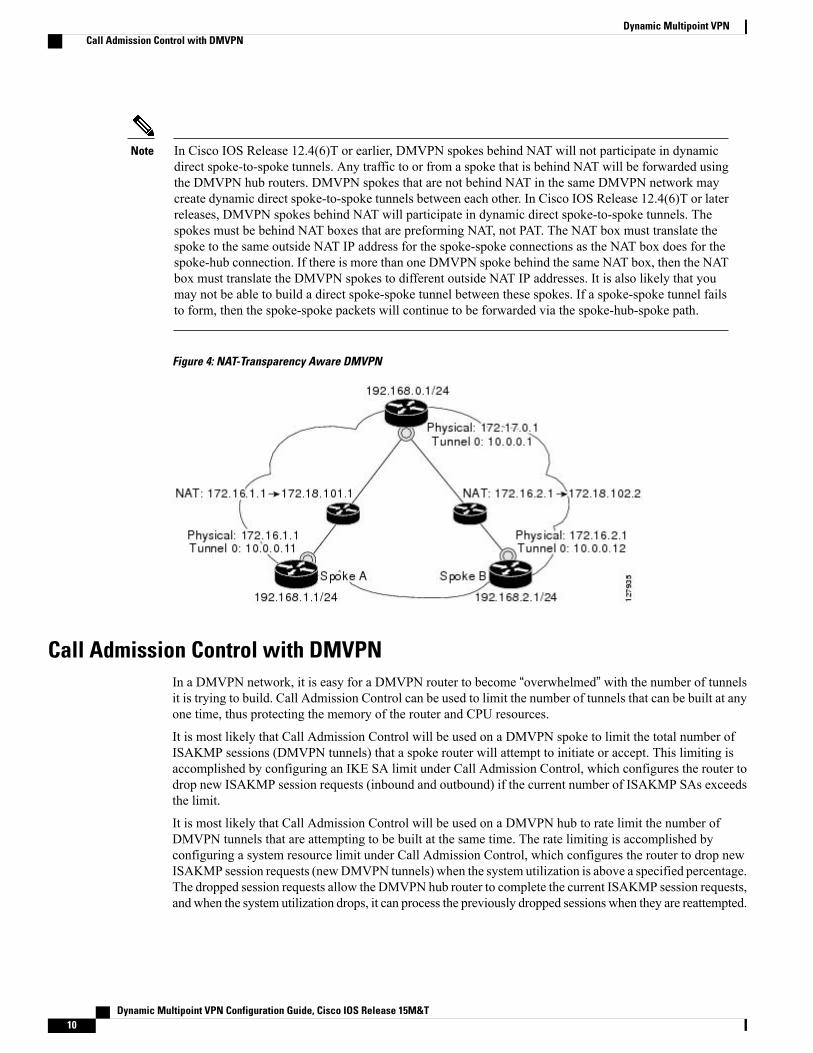
In Cisco IOS Release 12.4(6)T or earlier, DMVPN spokes behind NAT will not participate in dynamicdirect spoke-to-spoke tunnels. Any traffic to or from a spoke that is behind NAT will be forwarded usingthe DMVPN hub routers. DMVPN spokes that are not behind NAT in the same DMVPN network maycreate dynamic direct spoke-to-spoke tunnels between each other. In Cisco IOS Release 12.4(6)T or laterreleases, DMVPN spokes behind NAT will participate in dynamic direct spoke-to-spoke tunnels. Thespokes must be behind NAT boxes that are preforming NAT, not PAT. The NAT box must translate thespoke to the same outside NAT IP address for the spoke-spoke connections as the NAT box does for thespoke-hub connection. If there is more than one DMVPN spoke behind the same NAT box, then the NATbox must translate the DMVPN spokes to different outside NAT IP addresses. It is also likely that youmay not be able to build a direct spoke-spoke tunnel between these spokes. If a spoke-spoke tunnel failsto form, then the spoke-spoke packets will continue to be forwarded via the spoke-hub-spoke path.
Note
Figure 4: NAT-Transparency Aware DMVPN
Call Admission Control with DMVPNIn a DMVPN network, it is easy for a DMVPN router to become “overwhelmed” with the number of tunnelsit is trying to build. Call Admission Control can be used to limit the number of tunnels that can be built at anyone time, thus protecting the memory of the router and CPU resources.
It is most likely that Call Admission Control will be used on a DMVPN spoke to limit the total number ofISAKMP sessions (DMVPN tunnels) that a spoke router will attempt to initiate or accept. This limiting isaccomplished by configuring an IKE SA limit under Call Admission Control, which configures the router todrop new ISAKMP session requests (inbound and outbound) if the current number of ISAKMP SAs exceedsthe limit.
It is most likely that Call Admission Control will be used on a DMVPN hub to rate limit the number ofDMVPN tunnels that are attempting to be built at the same time. The rate limiting is accomplished byconfiguring a system resource limit under Call Admission Control, which configures the router to drop newISAKMP session requests (newDMVPN tunnels) when the system utilization is above a specified percentage.The dropped session requests allow the DMVPN hub router to complete the current ISAKMP session requests,and when the system utilization drops, it can process the previously dropped sessions when they are reattempted.
Dynamic Multipoint VPN Configuration Guide, Cisco IOS Release 15M&T10
Dynamic Multipoint VPNCall Admission Control with DMVPN
No special configuration is required to use Call Admission Control with DMVPN. For information aboutconfiguring Call Admission Control, see the reference in the section “Related Documents.”
NHRP Rate-Limiting MechanismNHRP has a rate-limitingmechanism that restricts the total number of NHRP packets from any given interface.The default values, which are set using the ip nhrp max-send command, are 100 packets every 10 secondsper interface. If the limit is exceeded, you will get the following system message:
%NHRP-4-QUOTA: Max-send quota of [int]pkts/[int]Sec. exceeded on [chars]For more information about this system message, see the document 12.4T System Message Guide.
How to Configure Dynamic Multipoint VPN (DMVPN)To enable mGRE and IPsec tunneling for hub and spoke routers, you must configure an IPsec profile thatuses a global IPsec policy template and configure your mGRE tunnel for IPsec encryption. This sectioncontains the following procedures:
Configuring an IPsec ProfileThe IPsec profile shares most of the same commands with the crypto map configuration, but only a subset ofthe commands are valid in an IPsec profile. Only commands that pertain to an IPsec policy can be issuedunder an IPsec profile; you cannot specify the IPsec peer address or the access control list (ACL) to matchthe packets that are to be encrypted.
Security threats, as well as the cryptographic technologies to help protect against them, are constantlychanging. For more information about the latest Cisco cryptographic recommendations, see the NextGeneration Encryption (NGE) white paper.
Note
Before You Begin
Before configuring an IPsec profile, you must define a transform set by using the crypto ipsec transform-setcommand.
SUMMARY STEPS
1. enable2. configure terminal3. crypto ipsec profile name4. set transform-set transform-set-name5. set identity6. set security association lifetime {seconds seconds | kilobytes kilobytes}7. set pfs [group1 | group14 | group15 | group16 | group19 | group2 | group20 | group24 | group5]
Dynamic Multipoint VPN Configuration Guide, Cisco IOS Release 15M&T 11
Dynamic Multipoint VPNNHRP Rate-Limiting Mechanism
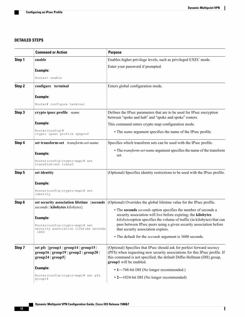
DETAILED STEPS
PurposeCommand or Action
Enables higher privilege levels, such as privileged EXEC mode.enableStep 1
Example:
Router> enable
Enter your password if prompted.
Enters global configuration mode.configure terminal
Example:
Router# configure terminal
Step 2
Defines the IPsec parameters that are to be used for IPsec encryptionbetween “spoke and hub” and “spoke and spoke” routers.
crypto ipsec profile name
Example:
Router(config)#crypto ipsec profile vpnprof
Step 3
This command enters crypto map configuration mode.
• The name argument specifies the name of the IPsec profile.
Specifies which transform sets can be used with the IPsec profile.set transform-set transform-set-nameStep 4
Example:
Router(config-crypto-map)# settransform-set trans2
• The transform-set-name argument specifies the name of the transformset.
(Optional) Specifies identity restrictions to be used with the IPsec profile.set identity
Example:
Router(config-crypto-map)# setidentity
Step 5
(Optional) Overrides the global lifetime value for the IPsec profile.set security association lifetime {secondsseconds | kilobytes kilobytes}
Step 6
• The seconds seconds option specifies the number of seconds asecurity association will live before expiring; the kilobytes
Example:
Router(config-crypto-map)# set
kilobytesoption specifies the volume of traffic (in kilobytes) that canpass between IPsec peers using a given security association beforethat security association expires.security association lifetime seconds
1800
• The default for the seconds argument is 3600 seconds.
(Optional) Specifies that IPsec should ask for perfect forward secrecy(PFS) when requesting new security associations for this IPsec profile. If
set pfs [group1 | group14 | group15 |group16 | group19 | group2 | group20 |group24 | group5]
Step 7
this command is not specified, the default Diffie-Hellman (DH) group,group1 will be enabled.
Example:
Router(config-crypto-map)# set pfsgroup14
• 1—768-bit DH (No longer recommended.)
• 2—1024-bit DH (No longer recommended)
Dynamic Multipoint VPN Configuration Guide, Cisco IOS Release 15M&T12
Dynamic Multipoint VPNConfiguring an IPsec Profile
PurposeCommand or Action
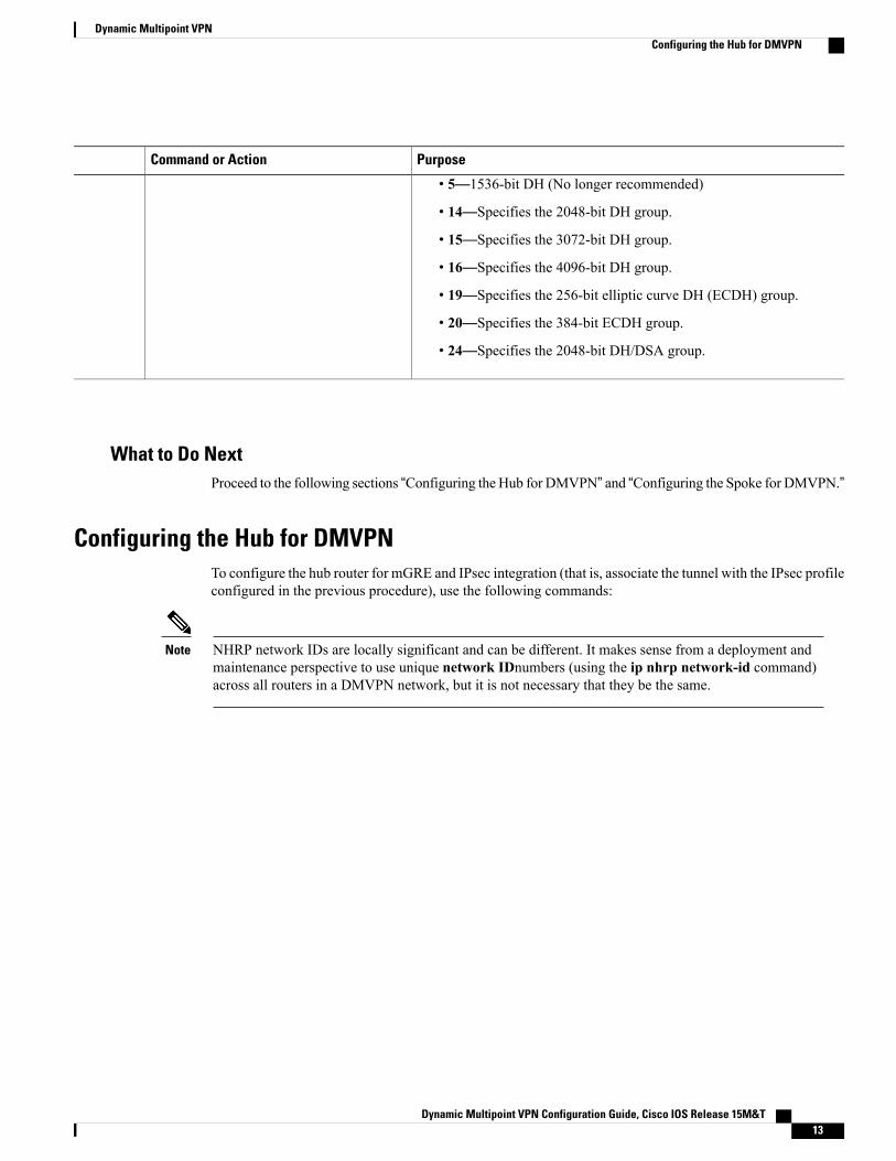
• 5—1536-bit DH (No longer recommended)
• 14—Specifies the 2048-bit DH group.
• 15—Specifies the 3072-bit DH group.
• 16—Specifies the 4096-bit DH group.
• 19—Specifies the 256-bit elliptic curve DH (ECDH) group.
• 20—Specifies the 384-bit ECDH group.
• 24—Specifies the 2048-bit DH/DSA group.
What to Do NextProceed to the following sections “Configuring the Hub for DMVPN” and “Configuring the Spoke for DMVPN.”
Configuring the Hub for DMVPNTo configure the hub router for mGRE and IPsec integration (that is, associate the tunnel with the IPsec profileconfigured in the previous procedure), use the following commands:
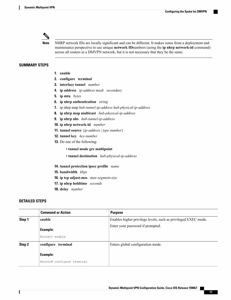
NHRP network IDs are locally significant and can be different. It makes sense from a deployment andmaintenance perspective to use unique network IDnumbers (using the ip nhrp network-id command)across all routers in a DMVPN network, but it is not necessary that they be the same.
Note
Dynamic Multipoint VPN Configuration Guide, Cisco IOS Release 15M&T 13
Dynamic Multipoint VPNConfiguring the Hub for DMVPN
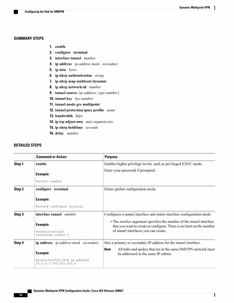
SUMMARY STEPS
1. enable2. configure terminal3. interface tunnel number4. ip address ip-address mask secondary5. ip mtu bytes6. ip nhrp authentication string7. ip nhrp map multicast dynamic8. ip nhrp network-id number9. tunnel source {ip-address | type number}10. tunnel key key-number11. tunnel mode gre multipoint12. tunnel protection ipsec profile name13. bandwidth kbps14. ip tcp adjust-mss max-segment-size15. ip nhrp holdtime seconds16. delay number
DETAILED STEPS
PurposeCommand or Action
Enables higher privilege levels, such as privileged EXEC mode.enableStep 1
Example:
Router> enable
Enter your password if prompted.
Enters global configuration mode.configure terminal
Example:
Router# configure terminal
Step 2
Configures a tunnel interface and enters interface configuration modeinterface tunnel numberStep 3
Example:
Router(config)#interface tunnel 5
• The number argument specifies the number of the tunnel interfacethat you want to create or configure. There is no limit on the numberof tunnel interfaces you can create.
Sets a primary or secondary IP address for the tunnel interface.ip address ip-address mask secondaryStep 4
Example:
Router(config-if)# ip address10.0.0.1 255.255.255.0
All hubs and spokes that are in the same DMVPN network mustbe addressed in the same IP subnet.
Note
Dynamic Multipoint VPN Configuration Guide, Cisco IOS Release 15M&T14
Dynamic Multipoint VPNConfiguring the Hub for DMVPN
PurposeCommand or Action
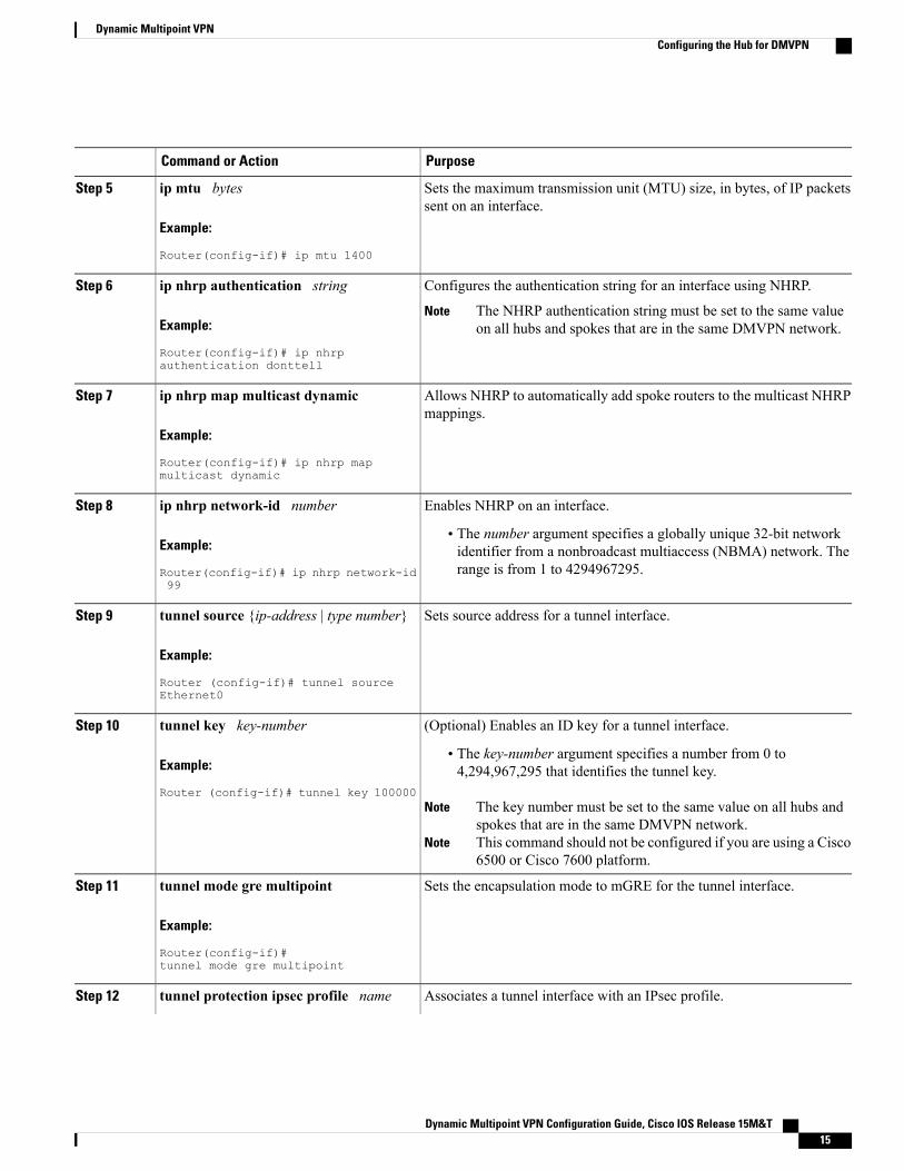
Sets the maximum transmission unit (MTU) size, in bytes, of IP packetssent on an interface.
ip mtu bytes
Example:
Router(config-if)# ip mtu 1400
Step 5
Configures the authentication string for an interface using NHRP.ip nhrp authentication stringStep 6
Example:
Router(config-if)# ip nhrpauthentication donttell
The NHRP authentication string must be set to the same valueon all hubs and spokes that are in the same DMVPN network.
Note
Allows NHRP to automatically add spoke routers to the multicast NHRPmappings.
ip nhrp map multicast dynamic
Example:
Router(config-if)# ip nhrp mapmulticast dynamic
Step 7
Enables NHRP on an interface.ip nhrp network-id numberStep 8
Example:
Router(config-if)# ip nhrp network-id99
• The number argument specifies a globally unique 32-bit networkidentifier from a nonbroadcast multiaccess (NBMA) network. Therange is from 1 to 4294967295.
Sets source address for a tunnel interface.tunnel source {ip-address | type number}
Example:
Router (config-if)# tunnel sourceEthernet0
Step 9
(Optional) Enables an ID key for a tunnel interface.tunnel key key-numberStep 10
Example:
Router (config-if)# tunnel key 100000
• The key-number argument specifies a number from 0 to4,294,967,295 that identifies the tunnel key.
The key number must be set to the same value on all hubs andspokes that are in the same DMVPN network.
Note
This command should not be configured if you are using a Cisco6500 or Cisco 7600 platform.
Note
Sets the encapsulation mode to mGRE for the tunnel interface.tunnel mode gre multipoint
Example:
Router(config-if)#tunnel mode gre multipoint
Step 11
Associates a tunnel interface with an IPsec profile.tunnel protection ipsec profile nameStep 12
Dynamic Multipoint VPN Configuration Guide, Cisco IOS Release 15M&T 15
Dynamic Multipoint VPNConfiguring the Hub for DMVPN
PurposeCommand or Action
Example:
Router(config-if)#
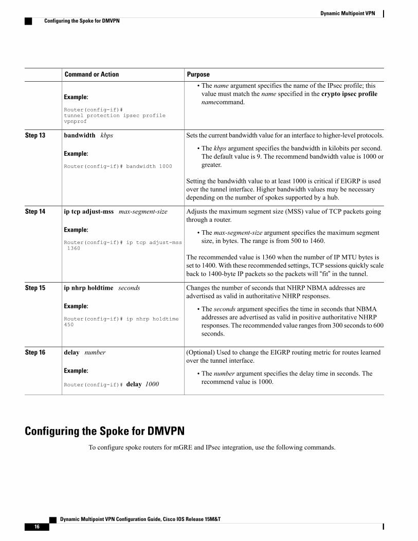
• The name argument specifies the name of the IPsec profile; thisvalue must match the name specified in the crypto ipsec profilenamecommand.
tunnel protection ipsec profilevpnprof
Sets the current bandwidth value for an interface to higher-level protocols.bandwidth kbpsStep 13
Example:
Router(config-if)# bandwidth 1000
• The kbps argument specifies the bandwidth in kilobits per second.The default value is 9. The recommend bandwidth value is 1000 orgreater.
Setting the bandwidth value to at least 1000 is critical if EIGRP is usedover the tunnel interface. Higher bandwidth values may be necessarydepending on the number of spokes supported by a hub.
Adjusts the maximum segment size (MSS) value of TCP packets goingthrough a router.
ip tcp adjust-mss max-segment-size
Example:
Router(config-if)# ip tcp adjust-mss1360
Step 14
• The max-segment-size argument specifies the maximum segmentsize, in bytes. The range is from 500 to 1460.
The recommended value is 1360 when the number of IP MTU bytes isset to 1400.With these recommended settings, TCP sessions quickly scaleback to 1400-byte IP packets so the packets will “fit” in the tunnel.
Changes the number of seconds that NHRP NBMA addresses areadvertised as valid in authoritative NHRP responses.
ip nhrp holdtime seconds
Example:
Router(config-if)# ip nhrp holdtime450
Step 15
• The seconds argument specifies the time in seconds that NBMAaddresses are advertised as valid in positive authoritative NHRPresponses. The recommended value ranges from 300 seconds to 600seconds.
(Optional) Used to change the EIGRP routing metric for routes learnedover the tunnel interface.
delay number
Example:
Router(config-if)# delay 1000
Step 16
• The number argument specifies the delay time in seconds. Therecommend value is 1000.
Configuring the Spoke for DMVPNTo configure spoke routers for mGRE and IPsec integration, use the following commands.
Dynamic Multipoint VPN Configuration Guide, Cisco IOS Release 15M&T16
Dynamic Multipoint VPNConfiguring the Spoke for DMVPN
NHRP network IDs are locally significant and can be different. It makes sense from a deployment andmaintenance perspective to use unique network IDnumbers (using the ip nhrp network-id command)across all routers in a DMVPN network, but it is not necessary that they be the same.
Note
SUMMARY STEPS
1. enable2. configure terminal3. interface tunnel number4. ip address ip-address mask secondary5. ip mtu bytes6. ip nhrp authentication string7. ip nhrp map hub-tunnel-ip-address hub-physical-ip-address8. ip nhrp map multicast hub-physical-ip-address9. ip nhrp nhs hub-tunnel-ip-address10. ip nhrp network-id number11. tunnel source {ip-address | type number}12. tunnel key key-number13. Do one of the following:
• tunnel mode gre multipoint
• tunnel destination hub-physical-ip-address
14. tunnel protection ipsec profile name15. bandwidth kbps16. ip tcp adjust-mss max-segment-size17. ip nhrp holdtime seconds18. delay number
DETAILED STEPS
PurposeCommand or Action
Enables higher privilege levels, such as privileged EXEC mode.enableStep 1
Example:
Router> enable
Enter your password if prompted.
Enters global configuration mode.configure terminal
Example:
Router# configure terminal
Step 2
Dynamic Multipoint VPN Configuration Guide, Cisco IOS Release 15M&T 17
Dynamic Multipoint VPNConfiguring the Spoke for DMVPN
PurposeCommand or Action
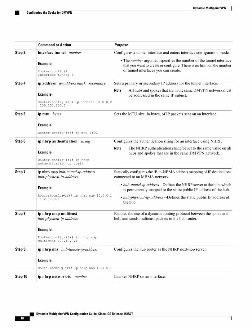
Configures a tunnel interface and enters interface configuration mode.interface tunnel numberStep 3
Example:
Router(config)#interface tunnel 5
• The number argument specifies the number of the tunnel interfacethat you want to create or configure. There is no limit on the numberof tunnel interfaces you can create.
Sets a primary or secondary IP address for the tunnel interface.ip address ip-address mask secondaryStep 4
Example:
Router(config-if)# ip address 10.0.0.2255.255.255.0
All hubs and spokes that are in the sameDMVPN networkmustbe addressed in the same IP subnet.
Note
Sets the MTU size, in bytes, of IP packets sent on an interface.ip mtu bytes
Example:
Router(config-if)# ip mtu 1400
Step 5
Configures the authentication string for an interface using NHRP.ip nhrp authentication stringStep 6
Example:
Router(config-if)# ip nhrpauthentication donttell
The NHRP authentication string be set to the same value on allhubs and spokes that are in the same DMVPN network.
Note
Statically configures the IP-to-NBMA address mapping of IP destinationsconnected to an MBMA network.
ip nhrp map hub-tunnel-ip-addresshub-physical-ip-address
Step 7
Example:
Router(config-if)# ip nhrp map 10.0.0.1172.17.0.1
• hub-tunnel-ip-address --Defines the NHRP server at the hub, whichis permanently mapped to the static public IP address of the hub.
• hub-physical-ip-address --Defines the static public IP address ofthe hub.
Enables the use of a dynamic routing protocol between the spoke andhub, and sends multicast packets to the hub router.
ip nhrp map multicasthub-physical-ip-address
Example:
Router(config-if)# ip nhrp mapmulticast 172.17.0.1
Step 8
Configures the hub router as the NHRP next-hop server.ip nhrp nhs hub-tunnel-ip-address
Example:
Router(config-if)# ip nhrp nhs 10.0.0.1
Step 9
Enables NHRP on an interface.ip nhrp network-id numberStep 10
Dynamic Multipoint VPN Configuration Guide, Cisco IOS Release 15M&T18
Dynamic Multipoint VPNConfiguring the Spoke for DMVPN
PurposeCommand or Action
Example:
Router(config-if)# ip nhrp network-id99
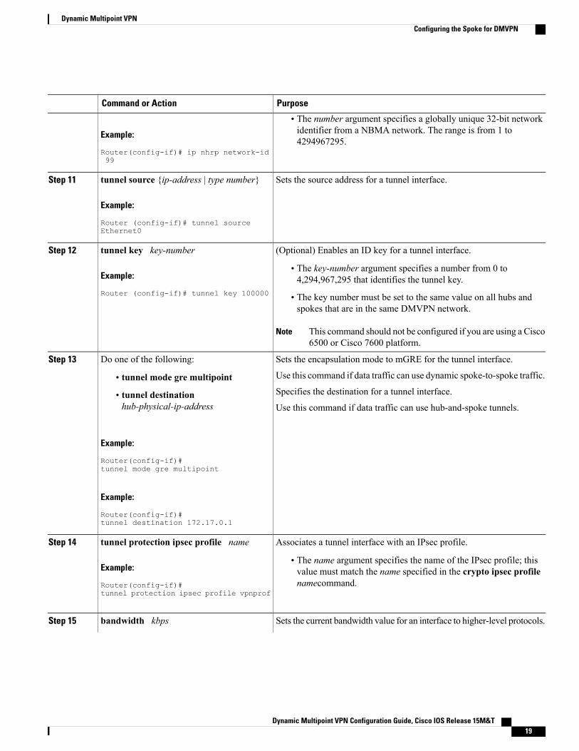
• The number argument specifies a globally unique 32-bit networkidentifier from a NBMA network. The range is from 1 to4294967295.
Sets the source address for a tunnel interface.tunnel source {ip-address | type number}
Example:
Router (config-if)# tunnel sourceEthernet0
Step 11
(Optional) Enables an ID key for a tunnel interface.tunnel key key-numberStep 12
Example:
Router (config-if)# tunnel key 100000
• The key-number argument specifies a number from 0 to4,294,967,295 that identifies the tunnel key.
• The key number must be set to the same value on all hubs andspokes that are in the same DMVPN network.
This command should not be configured if you are using a Cisco6500 or Cisco 7600 platform.
Note
Sets the encapsulation mode to mGRE for the tunnel interface.Do one of the following:Step 13
Use this command if data traffic can use dynamic spoke-to-spoke traffic.• tunnel mode gre multipointSpecifies the destination for a tunnel interface.• tunnel destination
hub-physical-ip-address Use this command if data traffic can use hub-and-spoke tunnels.
Example:
Router(config-if)#tunnel mode gre multipoint
Example:
Router(config-if)#tunnel destination 172.17.0.1
Associates a tunnel interface with an IPsec profile.tunnel protection ipsec profile nameStep 14
Example:
Router(config-if)#
• The name argument specifies the name of the IPsec profile; thisvalue must match the name specified in the crypto ipsec profilenamecommand.
tunnel protection ipsec profile vpnprof
Sets the current bandwidth value for an interface to higher-level protocols.bandwidth kbpsStep 15
Dynamic Multipoint VPN Configuration Guide, Cisco IOS Release 15M&T 19
Dynamic Multipoint VPNConfiguring the Spoke for DMVPN
PurposeCommand or Action
Example:
Router(config-if)# bandwidth 1000
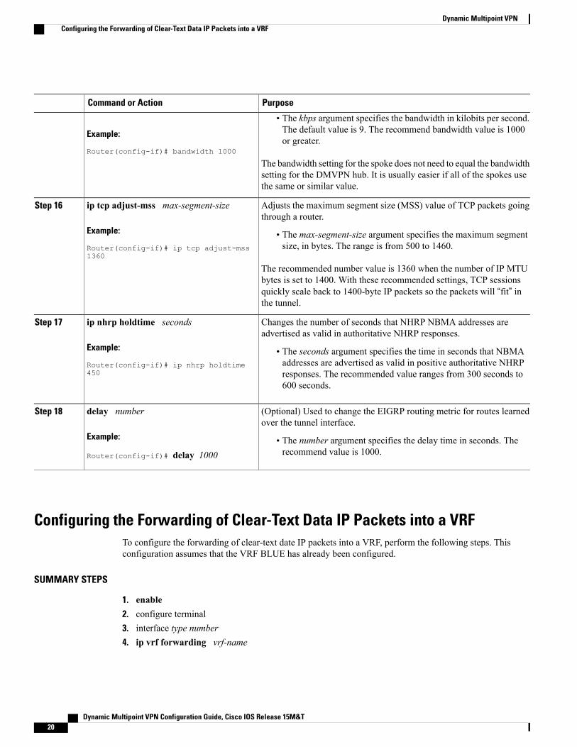
• The kbps argument specifies the bandwidth in kilobits per second.The default value is 9. The recommend bandwidth value is 1000or greater.
The bandwidth setting for the spoke does not need to equal the bandwidthsetting for the DMVPN hub. It is usually easier if all of the spokes usethe same or similar value.
Adjusts the maximum segment size (MSS) value of TCP packets goingthrough a router.
ip tcp adjust-mss max-segment-size
Example:
Router(config-if)# ip tcp adjust-mss1360
Step 16
• The max-segment-size argument specifies the maximum segmentsize, in bytes. The range is from 500 to 1460.
The recommended number value is 1360 when the number of IP MTUbytes is set to 1400. With these recommended settings, TCP sessionsquickly scale back to 1400-byte IP packets so the packets will “fit” inthe tunnel.
Changes the number of seconds that NHRP NBMA addresses areadvertised as valid in authoritative NHRP responses.
ip nhrp holdtime seconds
Example:
Router(config-if)# ip nhrp holdtime450
Step 17
• The seconds argument specifies the time in seconds that NBMAaddresses are advertised as valid in positive authoritative NHRPresponses. The recommended value ranges from 300 seconds to600 seconds.
(Optional) Used to change the EIGRP routing metric for routes learnedover the tunnel interface.
delay number
Example:
Router(config-if)# delay 1000
Step 18
• The number argument specifies the delay time in seconds. Therecommend value is 1000.
Configuring the Forwarding of Clear-Text Data IP Packets into a VRFTo configure the forwarding of clear-text date IP packets into a VRF, perform the following steps. Thisconfiguration assumes that the VRF BLUE has already been configured.
SUMMARY STEPS
1. enable2. configure terminal3. interface type number4. ip vrf forwarding vrf-name
Dynamic Multipoint VPN Configuration Guide, Cisco IOS Release 15M&T20
Dynamic Multipoint VPNConfiguring the Forwarding of Clear-Text Data IP Packets into a VRF
DETAILED STEPS
PurposeCommand or Action
Enables higher privilege levels, such as privileged EXECmode.
enable
Example:
Router> enable
Step 1
Enter your password if prompted.
Enters global configuration mode.configure terminal
Example:
Router# configure terminal
Step 2
Configures an interface type and enters interfaceconfiguration mode.
interface type number
Example:
Router (config)# interface tunnel0
Step 3
Associates a VPN VRF with an interface or subinterface.ip vrf forwarding vrf-name
Example:
Router (config-if)# ip vrf forwarding BLUE
Step 4
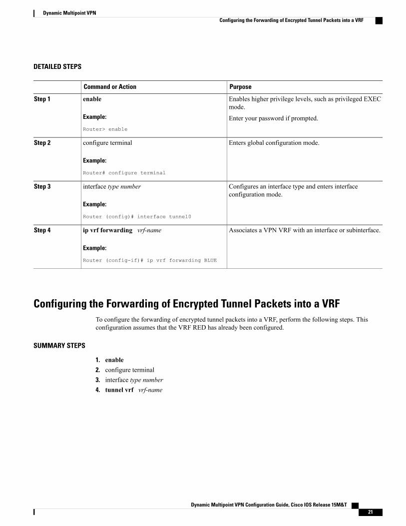
Configuring the Forwarding of Encrypted Tunnel Packets into a VRFTo configure the forwarding of encrypted tunnel packets into a VRF, perform the following steps. Thisconfiguration assumes that the VRF RED has already been configured.
SUMMARY STEPS
1. enable2. configure terminal3. interface type number4. tunnel vrf vrf-name
Dynamic Multipoint VPN Configuration Guide, Cisco IOS Release 15M&T 21
Dynamic Multipoint VPNConfiguring the Forwarding of Encrypted Tunnel Packets into a VRF
DETAILED STEPS
PurposeCommand or Action
Enables higher privilege levels, such as privileged EXECmode.
enable
Example:
Router> enable
Step 1
Enter your password if prompted.
Enters global configuration mode.configure terminal
Example:
Router# configure terminal
Step 2
Configures an interface type and enters interface configurationmode.
interface type number
Example:
Router (config)# interface tunnel0
Step 3
Associates a VPN VRF instance with a specific tunneldestination, interface, or subinterface.
tunnel vrf vrf-name
Example:
Router (config-if)# tunnel vrf RED
Step 4
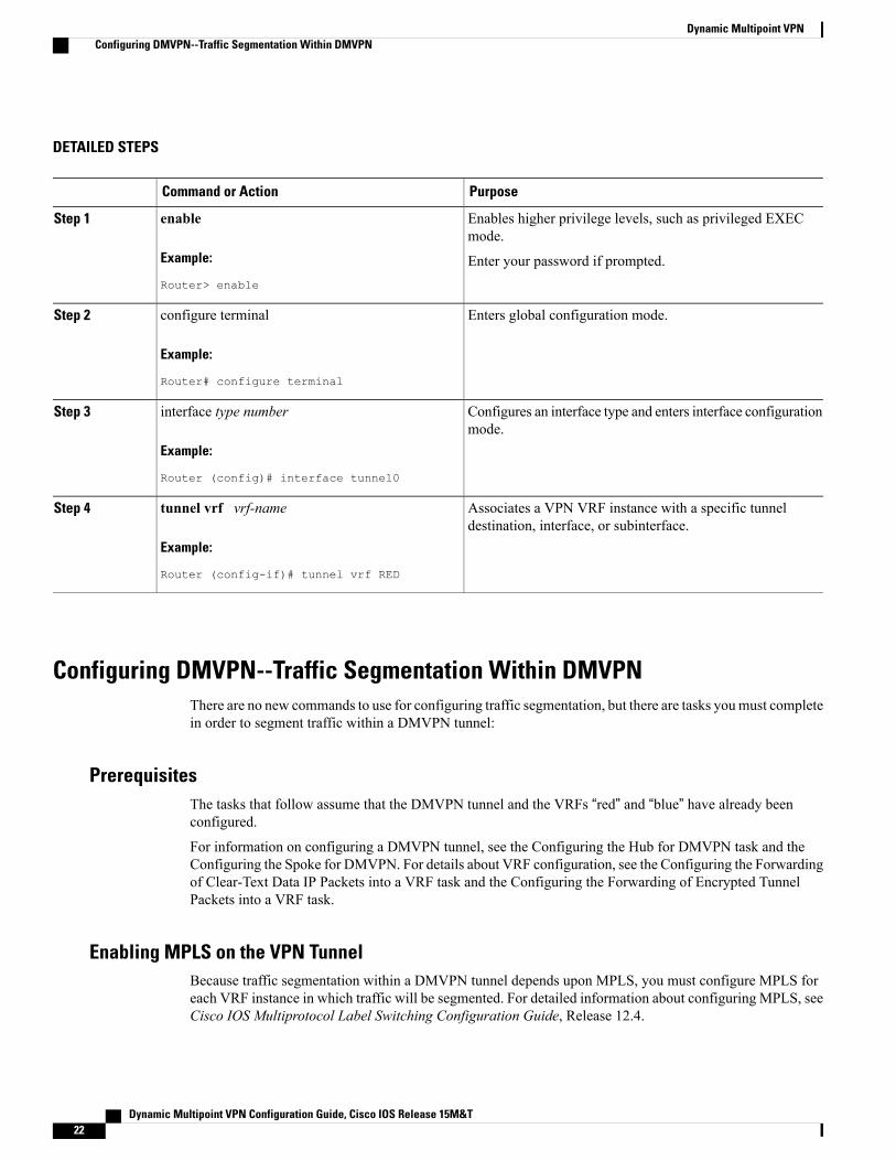
Configuring DMVPN--Traffic Segmentation Within DMVPNThere are no new commands to use for configuring traffic segmentation, but there are tasks youmust completein order to segment traffic within a DMVPN tunnel:
PrerequisitesThe tasks that follow assume that the DMVPN tunnel and the VRFs “red” and “blue” have already beenconfigured.
For information on configuring a DMVPN tunnel, see the Configuring the Hub for DMVPN task and theConfiguring the Spoke for DMVPN. For details about VRF configuration, see the Configuring the Forwardingof Clear-Text Data IP Packets into a VRF task and the Configuring the Forwarding of Encrypted TunnelPackets into a VRF task.
Enabling MPLS on the VPN TunnelBecause traffic segmentation within a DMVPN tunnel depends upon MPLS, you must configure MPLS foreach VRF instance in which traffic will be segmented. For detailed information about configuring MPLS, seeCisco IOS Multiprotocol Label Switching Configuration Guide, Release 12.4.
Dynamic Multipoint VPN Configuration Guide, Cisco IOS Release 15M&T22
Dynamic Multipoint VPNConfiguring DMVPN--Traffic Segmentation Within DMVPN
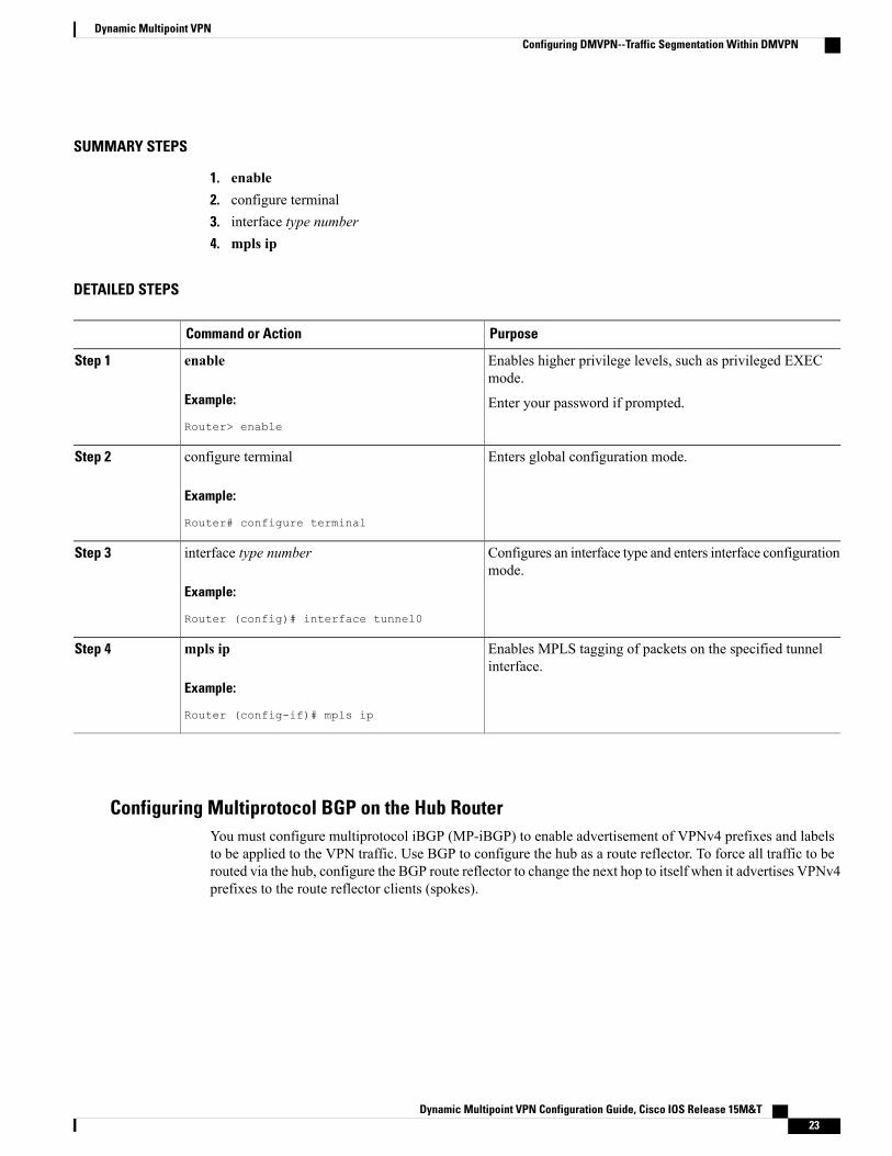
SUMMARY STEPS
1. enable2. configure terminal3. interface type number4. mpls ip
DETAILED STEPS
PurposeCommand or Action
Enables higher privilege levels, such as privileged EXECmode.
enable
Example:
Router> enable
Step 1
Enter your password if prompted.
Enters global configuration mode.configure terminal
Example:
Router# configure terminal
Step 2
Configures an interface type and enters interface configurationmode.
interface type number
Example:
Router (config)# interface tunnel0
Step 3
Enables MPLS tagging of packets on the specified tunnelinterface.
mpls ip
Example:
Router (config-if)# mpls ip
Step 4
Configuring Multiprotocol BGP on the Hub RouterYou must configure multiprotocol iBGP (MP-iBGP) to enable advertisement of VPNv4 prefixes and labelsto be applied to the VPN traffic. Use BGP to configure the hub as a route reflector. To force all traffic to berouted via the hub, configure the BGP route reflector to change the next hop to itself when it advertises VPNv4prefixes to the route reflector clients (spokes).
Dynamic Multipoint VPN Configuration Guide, Cisco IOS Release 15M&T 23
Dynamic Multipoint VPNConfiguring DMVPN--Traffic Segmentation Within DMVPN
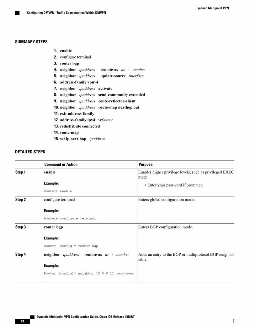
SUMMARY STEPS
1. enable2. configure terminal3. router bgp4. neighbor ipaddress remote-as as - number5. neighbor ipaddress update-source interface6. address-family vpnv47. neighbor ipaddress activate8. neighbor ipaddress send-community extended9. neighbor ipaddress route-reflector-client10. neighbor ipaddress route-map nexthop out11. exit-address-family12. address-family ipv4 vrf-name13. redistribute connected14. route-map15. set ip next-hop ipaddress
DETAILED STEPS
PurposeCommand or Action
Enables higher privilege levels, such as privileged EXECmode.
enable
Example:
Router> enable
Step 1
• Enter your password if prompted.
Enters global configuration mode.configure terminal
Example:
Router# configure terminal
Step 2
Enters BGP configuration mode.router bgp
Example:
Router (config)# router bgp
Step 3
Adds an entry to the BGP or multiprotocol BGP neighbortable.
neighbor ipaddress remote-as as - number
Example:
Router (config)# neighbor 10.0.0.11 remote-as1
Step 4
Dynamic Multipoint VPN Configuration Guide, Cisco IOS Release 15M&T24
Dynamic Multipoint VPNConfiguring DMVPN--Traffic Segmentation Within DMVPN
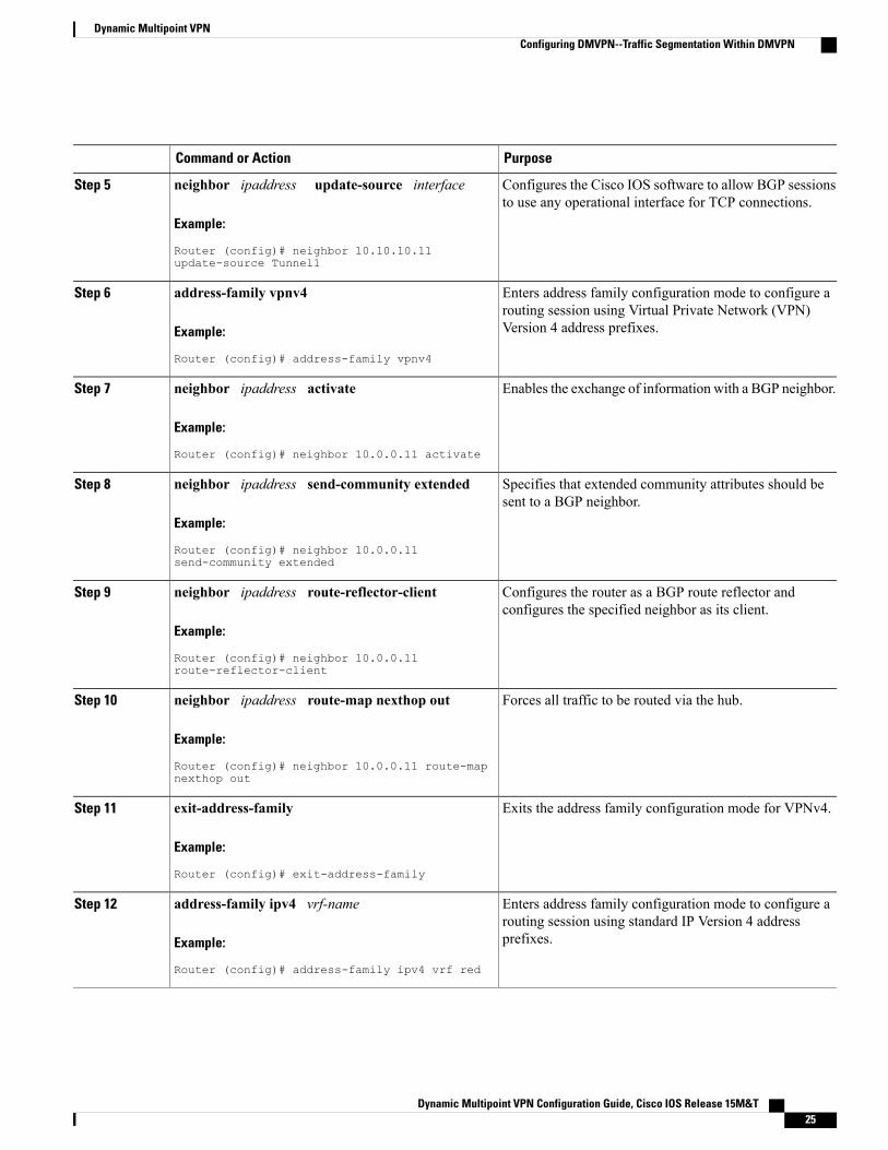
PurposeCommand or Action
Configures the Cisco IOS software to allow BGP sessionsto use any operational interface for TCP connections.
neighbor ipaddress update-source interface
Example:
Router (config)# neighbor 10.10.10.11update-source Tunnel1
Step 5
Enters address family configuration mode to configure arouting session using Virtual Private Network (VPN)Version 4 address prefixes.
address-family vpnv4
Example:
Router (config)# address-family vpnv4
Step 6
Enables the exchange of information with a BGP neighbor.neighbor ipaddress activateStep 7
Example:
Router (config)# neighbor 10.0.0.11 activate
Specifies that extended community attributes should besent to a BGP neighbor.
neighbor ipaddress send-community extended
Example:
Router (config)# neighbor 10.0.0.11send-community extended
Step 8
Configures the router as a BGP route reflector andconfigures the specified neighbor as its client.
neighbor ipaddress route-reflector-client
Example:
Router (config)# neighbor 10.0.0.11route-reflector-client
Step 9
Forces all traffic to be routed via the hub.neighbor ipaddress route-map nexthop out
Example:
Router (config)# neighbor 10.0.0.11 route-mapnexthop out
Step 10
Exits the address family configuration mode for VPNv4.exit-address-family
Example:
Router (config)# exit-address-family
Step 11
Enters address family configuration mode to configure arouting session using standard IP Version 4 addressprefixes.
address-family ipv4 vrf-name
Example:
Router (config)# address-family ipv4 vrf red
Step 12
Dynamic Multipoint VPN Configuration Guide, Cisco IOS Release 15M&T 25
Dynamic Multipoint VPNConfiguring DMVPN--Traffic Segmentation Within DMVPN
PurposeCommand or Action
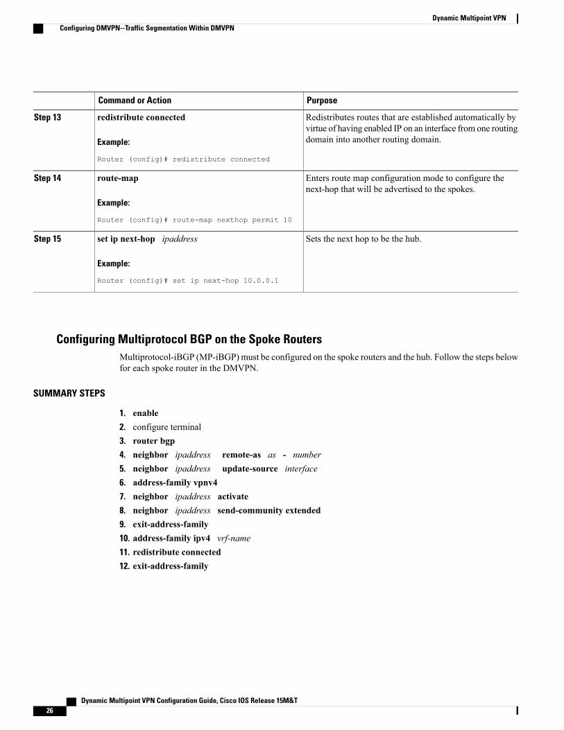
Redistributes routes that are established automatically byvirtue of having enabled IP on an interface from one routingdomain into another routing domain.
redistribute connected
Example:
Router (config)# redistribute connected
Step 13
Enters route map configuration mode to configure thenext-hop that will be advertised to the spokes.
route-map
Example:
Router (config)# route-map nexthop permit 10
Step 14
Sets the next hop to be the hub.set ip next-hop ipaddress
Example:
Router (config)# set ip next-hop 10.0.0.1
Step 15
Configuring Multiprotocol BGP on the Spoke RoutersMultiprotocol-iBGP (MP-iBGP) must be configured on the spoke routers and the hub. Follow the steps belowfor each spoke router in the DMVPN.
SUMMARY STEPS
1. enable2. configure terminal3. router bgp4. neighbor ipaddress remote-as as - number5. neighbor ipaddress update-source interface6. address-family vpnv47. neighbor ipaddress activate8. neighbor ipaddress send-community extended9. exit-address-family10. address-family ipv4 vrf-name11. redistribute connected12. exit-address-family
Dynamic Multipoint VPN Configuration Guide, Cisco IOS Release 15M&T26
Dynamic Multipoint VPNConfiguring DMVPN--Traffic Segmentation Within DMVPN
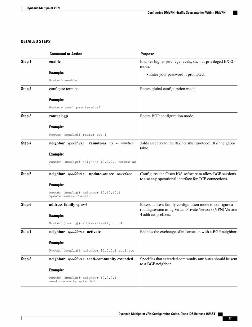
DETAILED STEPS
PurposeCommand or Action
Enables higher privilege levels, such as privileged EXECmode.
enable
Example:
Router> enable
Step 1
• Enter your password if prompted.
Enters global configuration mode.configure terminal
Example:
Router# configure terminal
Step 2
Enters BGP configuration mode.router bgp
Example:
Router (config)# router bgp 1
Step 3
Adds an entry to the BGP or multiprotocol BGP neighbortable.
neighbor ipaddress remote-as as - number
Example:
Router (config)# neighbor 10.0.0.1 remote-as1
Step 4
Configures the Cisco IOS software to allow BGP sessionsto use any operational interface for TCP connections.
neighbor ipaddress update-source interface
Example:
Router (config)# neighbor 10.10.10.1update-source Tunnel1
Step 5
Enters address family configuration mode to configure arouting session using Virtual Private Network (VPN)Version4 address prefixes.
address-family vpnv4
Example:
Router (config)# address-family vpnv4
Step 6
Enables the exchange of information with a BGP neighbor.neighbor ipaddress activateStep 7
Example:
Router (config)# neighbor 10.0.0.1 activate
Specifies that extended community attributes should be sentto a BGP neighbor.
neighbor ipaddress send-community extended
Example:
Router (config)# neighbor 10.0.0.1send-community extended
Step 8
Dynamic Multipoint VPN Configuration Guide, Cisco IOS Release 15M&T 27
Dynamic Multipoint VPNConfiguring DMVPN--Traffic Segmentation Within DMVPN
PurposeCommand or Action
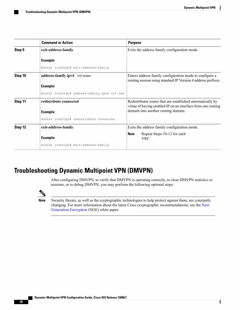
Exits the address family configuration mode.exit-address-family
Example:
Router (config)# exit-address-family
Step 9
Enters address family configuration mode to configure arouting session using standard IP Version 4 address prefixes.
address-family ipv4 vrf-name
Example:
Router (config)# address-family ipv4 vrf red
Step 10
Redistributes routes that are established automatically byvirtue of having enabled IP on an interface from one routingdomain into another routing domain.
redistribute connected
Example:
Router (config)# redistribute connected
Step 11
Exits the address family configuration mode.exit-address-familyStep 12
Example:
Router (config)# exit-address-family
Repeat Steps 10-12 for eachVRF.
Note
Troubleshooting Dynamic Multipoint VPN (DMVPN)After configuring DMVPN, to verify that DMVPN is operating correctly, to clear DMVPN statistics orsessions, or to debug DMVPN, you may perform the following optional steps:
Security threats, as well as the cryptographic technologies to help protect against them, are constantlychanging. For more information about the latest Cisco cryptographic recommendations, see the NextGeneration Encryption (NGE) white paper.
Note
Dynamic Multipoint VPN Configuration Guide, Cisco IOS Release 15M&T28
Dynamic Multipoint VPNTroubleshooting Dynamic Multipoint VPN (DMVPN)
SUMMARY STEPS
1. The clear dmvpn session command is used to clear DMVPN sessions.2. The clear dmvpn statistics command is used to clear DMVPN related counters. The following example
shows how to clear DMVPN related session counters for the specified tunnel interface:3. The debug dmvpn command is used to debug DMVPN sessions. You can enable or disable DMVPN
debugging based on a specific condition. There are three levels of DMVPN debugging, listed in the orderof details from lowest to highest:
4. The debug nhrp conditioncommand enables or disables debugging based on a specific condition. Thefollowing example shows how to enable conditional NHRP debugging:
5. The debug nhrp errorcommand displays information about NHRP error activity. The following exampleshows how to enable debugging for NHRP error messages:
6. The logging dmvpn command is used to enable DMVPN system logging. The following command showshow to enable DMVPN system logging at the rate of 1 message every 20 seconds:
7. The show crypto ipsec sacommand displays the settings used by the current SAs. The following exampleoutput shows the IPsec SA status of only the active device:
8. The show crypto isakmp sacommand displays all current IKE SAs at a peer. For example, the followingsample output is displayed after IKE negotiations have successfully completed between two peers.
9. The show crypto map command displays the crypto map configuration.10. The show dmvpn command displays DMVPN specific session information. The following example shows
example summary output:11. The show ip nhrp trafficcommand displays NHRP statistics. The following example shows output for a
specific tunnel, tunnel7:
DETAILED STEPS
Step 1 The clear dmvpn session command is used to clear DMVPN sessions.The following example clears only dynamic DMVPN sessions:
Router# clear dmvpn session peer nbma
The following example clears all DMVPN sessions, both static and dynamic, for the specified tunnel:
Router# clear dmvpn session interface tunnel 100 static
Step 2 The clear dmvpn statistics command is used to clear DMVPN related counters. The following example shows how toclear DMVPN related session counters for the specified tunnel interface:Router# clear dmvpn statistics peer tunnel 192.0.2.3
Step 3 The debug dmvpn command is used to debug DMVPN sessions. You can enable or disable DMVPN debugging basedon a specific condition. There are three levels of DMVPN debugging, listed in the order of details from lowest to highest:
• Error level
• Detail level
• Packet level
The following example shows how to enable conditional DMVPN debugging that displays all error debugs for next hoprouting protocol (NHRP), sockets, tunnel protection and crypto information: Router# debug dmvpn error all
Dynamic Multipoint VPN Configuration Guide, Cisco IOS Release 15M&T 29
Dynamic Multipoint VPNTroubleshooting Dynamic Multipoint VPN (DMVPN)
Step 4 The debug nhrp conditioncommand enables or disables debugging based on a specific condition. The following exampleshows how to enable conditional NHRP debugging:Router# debug nhrp condition
Step 5 The debug nhrp errorcommand displays information about NHRP error activity. The following example shows howto enable debugging for NHRP error messages:Router# debug nhrp error
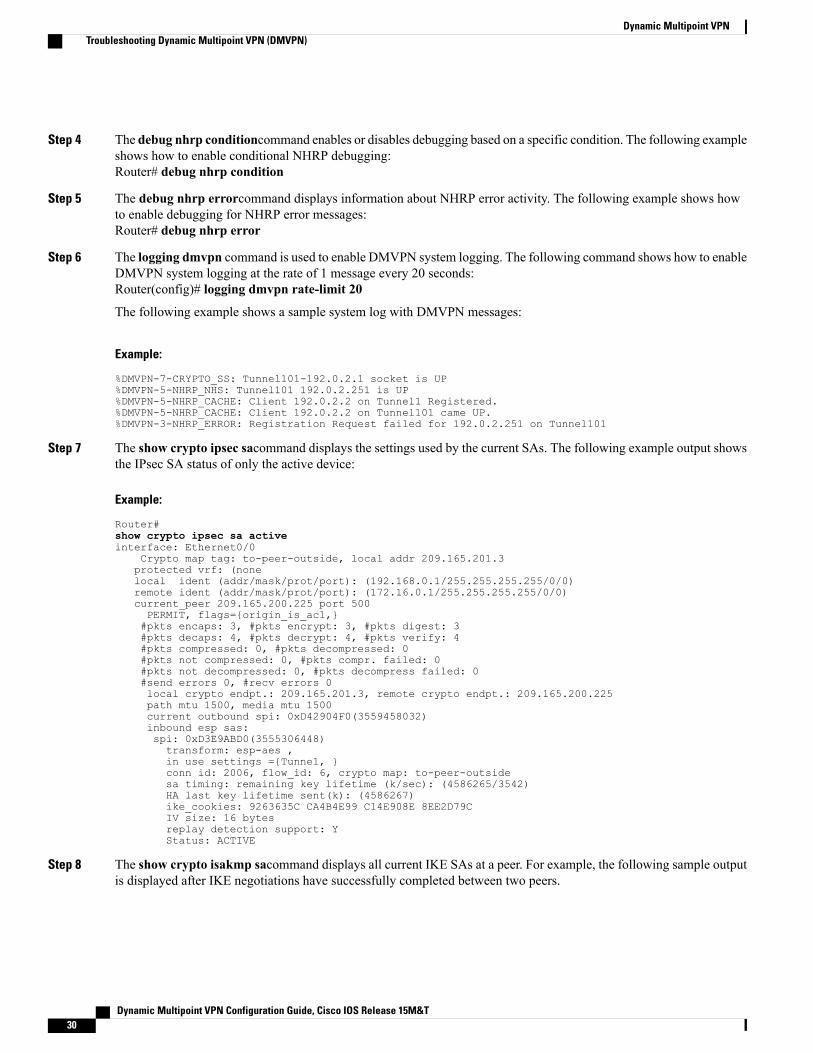
Step 6 The logging dmvpn command is used to enable DMVPN system logging. The following command shows how to enableDMVPN system logging at the rate of 1 message every 20 seconds:Router(config)# logging dmvpn rate-limit 20
The following example shows a sample system log with DMVPN messages:
Example:
%DMVPN-7-CRYPTO_SS: Tunnel101-192.0.2.1 socket is UP%DMVPN-5-NHRP_NHS: Tunnel101 192.0.2.251 is UP%DMVPN-5-NHRP_CACHE: Client 192.0.2.2 on Tunnel1 Registered.%DMVPN-5-NHRP_CACHE: Client 192.0.2.2 on Tunnel101 came UP.%DMVPN-3-NHRP_ERROR: Registration Request failed for 192.0.2.251 on Tunnel101
Step 7 The show crypto ipsec sacommand displays the settings used by the current SAs. The following example output showsthe IPsec SA status of only the active device:
Example:
Router#show crypto ipsec sa activeinterface: Ethernet0/0
Crypto map tag: to-peer-outside, local addr 209.165.201.3protected vrf: (nonelocal ident (addr/mask/prot/port): (192.168.0.1/255.255.255.255/0/0)remote ident (addr/mask/prot/port): (172.16.0.1/255.255.255.255/0/0)current_peer 209.165.200.225 port 500PERMIT, flags={origin_is_acl,}#pkts encaps: 3, #pkts encrypt: 3, #pkts digest: 3#pkts decaps: 4, #pkts decrypt: 4, #pkts verify: 4#pkts compressed: 0, #pkts decompressed: 0#pkts not compressed: 0, #pkts compr. failed: 0#pkts not decompressed: 0, #pkts decompress failed: 0#send errors 0, #recv errors 0local crypto endpt.: 209.165.201.3, remote crypto endpt.: 209.165.200.225path mtu 1500, media mtu 1500current outbound spi: 0xD42904F0(3559458032)inbound esp sas:spi: 0xD3E9ABD0(3555306448)transform: esp-aes ,in use settings ={Tunnel, }conn id: 2006, flow_id: 6, crypto map: to-peer-outsidesa timing: remaining key lifetime (k/sec): (4586265/3542)HA last key lifetime sent(k): (4586267)ike_cookies: 9263635C CA4B4E99 C14E908E 8EE2D79CIV size: 16 bytesreplay detection support: YStatus: ACTIVE
Step 8 The show crypto isakmp sacommand displays all current IKE SAs at a peer. For example, the following sample outputis displayed after IKE negotiations have successfully completed between two peers.
Dynamic Multipoint VPN Configuration Guide, Cisco IOS Release 15M&T30
Dynamic Multipoint VPNTroubleshooting Dynamic Multipoint VPN (DMVPN)
Example:
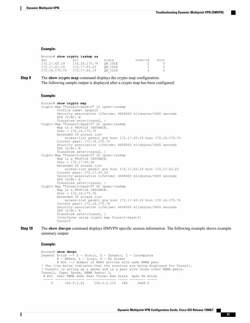
Router# show crypto isakmp sadst src state conn-id slot172.17.63.19 172.16.175.76 QM_IDLE 2 0172.17.63.19 172.17.63.20 QM_IDLE 1 0172.16.175.75 172.17.63.19 QM_IDLE 3 0
Step 9 The show crypto map command displays the crypto map configuration.The following sample output is displayed after a crypto map has been configured:
Example:
Router# show crypto mapCrypto Map "Tunnel5-head-0" 10 ipsec-isakmp
Profile name: vpnprofSecurity association lifetime: 4608000 kilobytes/3600 secondsPFS (Y/N): NTransform sets={trans2, }
Crypto Map "Tunnel5-head-0" 20 ipsec-isakmpMap is a PROFILE INSTANCE.Peer = 172.16.175.75Extended IP access list
access-list permit gre host 172.17.63.19 host 172.16.175.75Current peer: 172.16.175.75Security association lifetime: 4608000 kilobytes/3600 secondsPFS (Y/N): NTransform sets={trans2, }
Crypto Map "Tunnel5-head-0" 30 ipsec-isakmpMap is a PROFILE INSTANCE.Peer = 172.17.63.20Extended IP access list
access-list permit gre host 172.17.63.19 host 172.17.63.20Current peer: 172.17.63.20Security association lifetime: 4608000 kilobytes/3600 secondsPFS (Y/N): NTransform sets={trans2, }
Crypto Map "Tunnel5-head-0" 40 ipsec-isakmpMap is a PROFILE INSTANCE.Peer = 172.16.175.76Extended IP access list
access-list permit gre host 172.17.63.19 host 172.16.175.76Current peer: 172.16.175.76Security association lifetime: 4608000 kilobytes/3600 secondsPFS (Y/N): NTransform sets={trans2, }Interfaces using crypto map Tunnel5-head-0:Tunnel5
Step 10 The show dmvpn command displays DMVPN specific session information. The following example shows examplesummary output:
Example:
Router# show dmvpnLegend: Attrb --> S - Static, D - Dynamic, I - Incomplete
N - NATed, L - Local, X - No Socket# Ent --> Number of NHRP entries with same NBMA peer
! The line below indicates that the sessions are being displayed for Tunnel1.! Tunnel1 is acting as a spoke and is a peer with three other NBMA peers.Tunnel1, Type: Spoke, NBMA Peers: 3,# Ent Peer NBMA Addr Peer Tunnel Add State UpDn Tm Attrb----- --------------- --------------- ----- -------- -----
2 192.0.2.21 192.0.2.116 IKE 3w0d D
Dynamic Multipoint VPN Configuration Guide, Cisco IOS Release 15M&T 31
Dynamic Multipoint VPNTroubleshooting Dynamic Multipoint VPN (DMVPN)
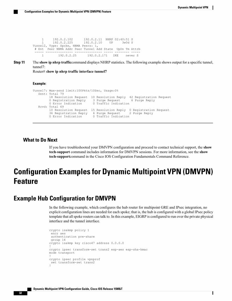
1 192.0.2.102 192.0.2.11 NHRP 02:40:51 S1 192.0.2.225 192.0.2.10 UP 3w0d S
Tunnel2, Type: Spoke, NBMA Peers: 1,# Ent Peer NBMA Addr Peer Tunnel Add State UpDn Tm Attrb----- --------------- --------------- ----- -------- -----
1 192.0.2.25 192.0.2.171 IKE never S
Step 11 The show ip nhrp trafficcommand displays NHRP statistics. The following example shows output for a specific tunnel,tunnel7:Router# show ip nhrp traffic interface tunnel7
Example:
Tunnel7: Max-send limit:100Pkts/10Sec, Usage:0%Sent: Total 79
18 Resolution Request 10 Resolution Reply 42 Registration Request0 Registration Reply 3 Purge Request 6 Purge Reply0 Error Indication 0 Traffic Indication
Rcvd: Total 6910 Resolution Request 15 Resolution Reply 0 Registration Request36 Registration Reply 6 Purge Request 2 Purge Reply0 Error Indication 0 Traffic Indication
What to Do NextIf you have troubleshooted your DMVPN configuration and proceed to contact technical support, the showtech-support command includes information for DMVPN sessions. For more information, see the showtech-supportcommand in the Cisco IOS Configuration Fundamentals Command Reference.
Configuration Examples for Dynamic Multipoint VPN (DMVPN)Feature
Example Hub Configuration for DMVPNIn the following example, which configures the hub router for multipoint GRE and IPsec integration, noexplicit configuration lines are needed for each spoke; that is, the hub is configured with a global IPsec policytemplate that all spoke routers can talk to. In this example, EIGRP is configured to run over the private physicalinterface and the tunnel interface.
crypto isakmp policy 1encr aesauthentication pre-sharegroup 14crypto isakmp key cisco47 address 0.0.0.0!crypto ipsec transform-set trans2 esp-aes esp-sha-hmacmode transport!crypto ipsec profile vpnprofset transform-set trans2!
Dynamic Multipoint VPN Configuration Guide, Cisco IOS Release 15M&T32
Dynamic Multipoint VPNConfiguration Examples for Dynamic Multipoint VPN (DMVPN) Feature
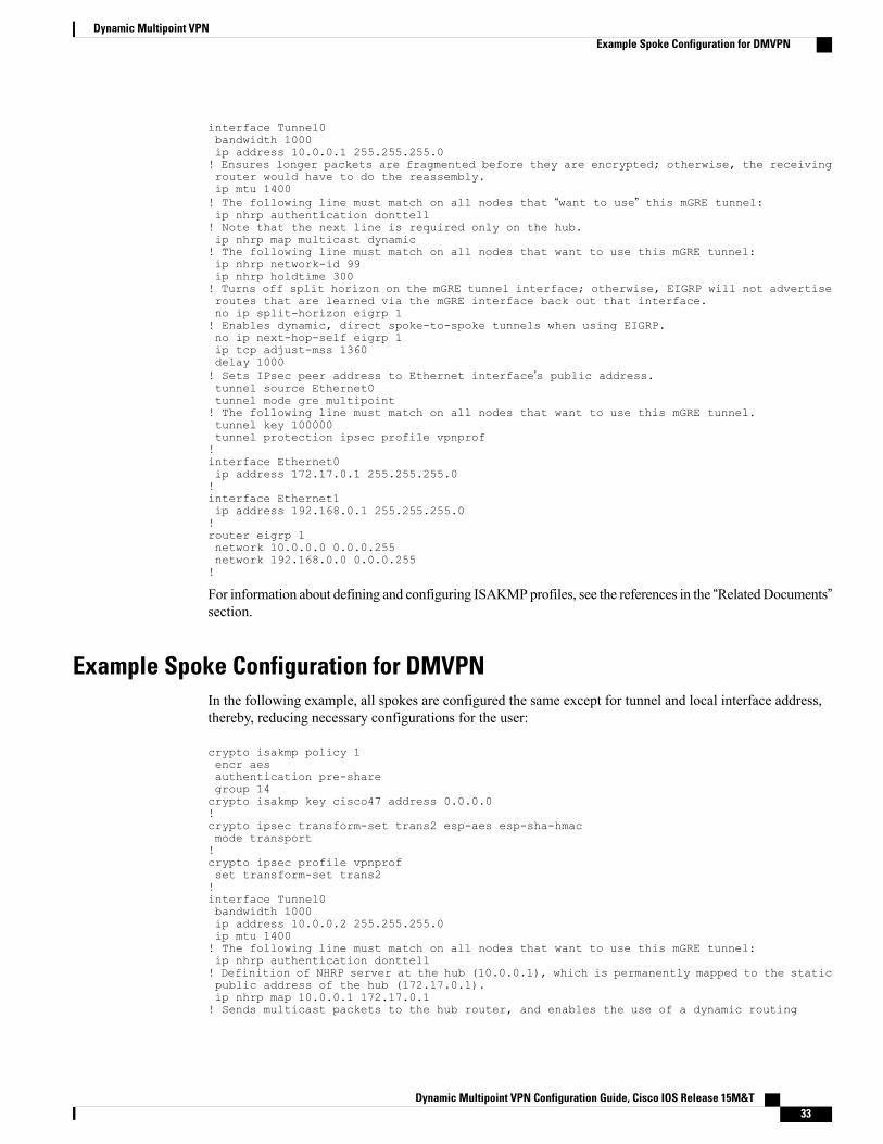
interface Tunnel0bandwidth 1000ip address 10.0.0.1 255.255.255.0! Ensures longer packets are fragmented before they are encrypted; otherwise, the receivingrouter would have to do the reassembly.ip mtu 1400! The following line must match on all nodes that “want to use” this mGRE tunnel:ip nhrp authentication donttell! Note that the next line is required only on the hub.ip nhrp map multicast dynamic! The following line must match on all nodes that want to use this mGRE tunnel:ip nhrp network-id 99ip nhrp holdtime 300! Turns off split horizon on the mGRE tunnel interface; otherwise, EIGRP will not advertiseroutes that are learned via the mGRE interface back out that interface.no ip split-horizon eigrp 1! Enables dynamic, direct spoke-to-spoke tunnels when using EIGRP.no ip next-hop-self eigrp 1ip tcp adjust-mss 1360delay 1000! Sets IPsec peer address to Ethernet interface’s public address.tunnel source Ethernet0tunnel mode gre multipoint! The following line must match on all nodes that want to use this mGRE tunnel.tunnel key 100000tunnel protection ipsec profile vpnprof!interface Ethernet0ip address 172.17.0.1 255.255.255.0!interface Ethernet1ip address 192.168.0.1 255.255.255.0!router eigrp 1network 10.0.0.0 0.0.0.255network 192.168.0.0 0.0.0.255!
For information about defining and configuring ISAKMP profiles, see the references in the “RelatedDocuments”section.
Example Spoke Configuration for DMVPNIn the following example, all spokes are configured the same except for tunnel and local interface address,thereby, reducing necessary configurations for the user:
crypto isakmp policy 1encr aesauthentication pre-sharegroup 14crypto isakmp key cisco47 address 0.0.0.0!crypto ipsec transform-set trans2 esp-aes esp-sha-hmacmode transport!crypto ipsec profile vpnprofset transform-set trans2!interface Tunnel0bandwidth 1000ip address 10.0.0.2 255.255.255.0ip mtu 1400! The following line must match on all nodes that want to use this mGRE tunnel:ip nhrp authentication donttell! Definition of NHRP server at the hub (10.0.0.1), which is permanently mapped to the staticpublic address of the hub (172.17.0.1).ip nhrp map 10.0.0.1 172.17.0.1! Sends multicast packets to the hub router, and enables the use of a dynamic routing
Dynamic Multipoint VPN Configuration Guide, Cisco IOS Release 15M&T 33
Dynamic Multipoint VPNExample Spoke Configuration for DMVPN
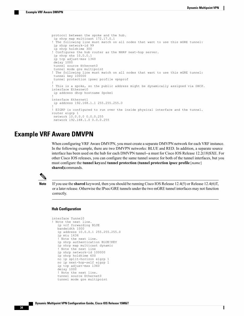
protocol between the spoke and the hub.ip nhrp map multicast 172.17.0.1! The following line must match on all nodes that want to use this mGRE tunnel:ip nhrp network-id 99ip nhrp holdtime 300! Configures the hub router as the NHRP next-hop server.ip nhrp nhs 10.0.0.1ip tcp adjust-mss 1360delay 1000tunnel source Ethernet0tunnel mode gre multipoint! The following line must match on all nodes that want to use this mGRE tunnel:tunnel key 100000tunnel protection ipsec profile vpnprof!! This is a spoke, so the public address might be dynamically assigned via DHCP.interface Ethernet0ip address dhcp hostname Spoke1!interface Ethernet1ip address 192.168.1.1 255.255.255.0!! EIGRP is configured to run over the inside physical interface and the tunnel.router eigrp 1network 10.0.0.0 0.0.0.255network 192.168.1.0 0.0.0.255
Example VRF Aware DMVPNWhen configuring VRFAware DMVPN, you must create a separate DMVPN network for each VRF instance.In the following example, there are two DMVPN networks: BLUE and RED. In addition, a separate sourceinterface has been used on the hub for each DMVPN tunnel--a must for Cisco IOS Release 12.2(18)SXE. Forother Cisco IOS releases, you can configure the same tunnel source for both of the tunnel interfaces, but youmust configure the tunnel keyand tunnel protection (tunnel protection ipsec profile{name}shared)commands.
If you use the shared keyword, then you should be running Cisco IOS Release 12.4(5) or Release 12.4(6)T,or a later release. Otherwise the IPsec/GRE tunnels under the twomGRE tunnel interfaces may not functioncorrectly.
Note
Hub Configuration
interface Tunnel0! Note the next line.
ip vrf forwarding BLUEbandwidth 1000ip address 10.0.0.1 255.255.255.0ip mtu 1436! Note the next line.ip nhrp authentication BLUE!KEYip nhrp map multicast dynamic! Note the next lineip nhrp network-id 100000ip nhrp holdtime 600no ip split-horizon eigrp 1no ip next-hop-self eigrp 1ip tcp adjust-mss 1360delay 1000! Note the next line.tunnel source Ethernet0tunnel mode gre multipoint
Dynamic Multipoint VPN Configuration Guide, Cisco IOS Release 15M&T34
Dynamic Multipoint VPNExample VRF Aware DMVPN
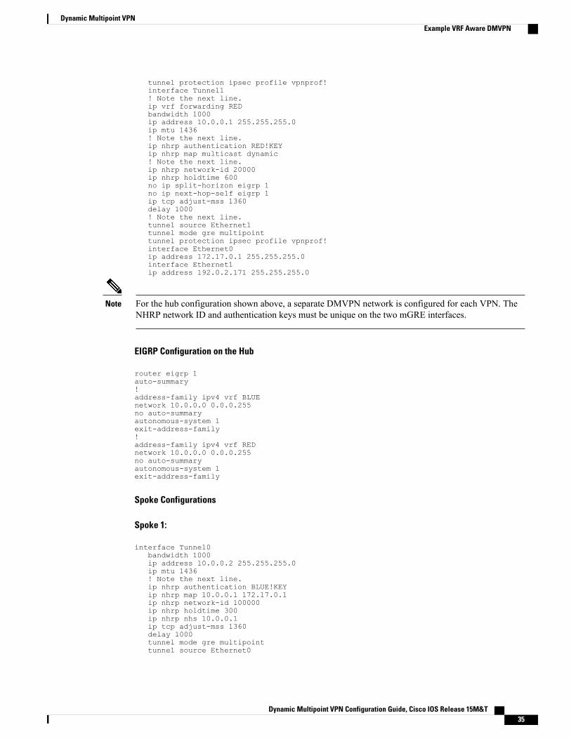
tunnel protection ipsec profile vpnprof!interface Tunnel1! Note the next line.ip vrf forwarding REDbandwidth 1000ip address 10.0.0.1 255.255.255.0ip mtu 1436! Note the next line.ip nhrp authentication RED!KEYip nhrp map multicast dynamic! Note the next line.ip nhrp network-id 20000ip nhrp holdtime 600no ip split-horizon eigrp 1no ip next-hop-self eigrp 1ip tcp adjust-mss 1360delay 1000! Note the next line.tunnel source Ethernet1tunnel mode gre multipointtunnel protection ipsec profile vpnprof!interface Ethernet0ip address 172.17.0.1 255.255.255.0interface Ethernet1ip address 192.0.2.171 255.255.255.0
For the hub configuration shown above, a separate DMVPN network is configured for each VPN. TheNHRP network ID and authentication keys must be unique on the two mGRE interfaces.
Note
EIGRP Configuration on the Hub
router eigrp 1auto-summary!address-family ipv4 vrf BLUEnetwork 10.0.0.0 0.0.0.255no auto-summaryautonomous-system 1exit-address-family!address-family ipv4 vrf REDnetwork 10.0.0.0 0.0.0.255no auto-summaryautonomous-system 1exit-address-family
Spoke Configurations
Spoke 1:
interface Tunnel0bandwidth 1000ip address 10.0.0.2 255.255.255.0ip mtu 1436! Note the next line.ip nhrp authentication BLUE!KEYip nhrp map 10.0.0.1 172.17.0.1ip nhrp network-id 100000ip nhrp holdtime 300ip nhrp nhs 10.0.0.1ip tcp adjust-mss 1360delay 1000tunnel mode gre multipointtunnel source Ethernet0
Dynamic Multipoint VPN Configuration Guide, Cisco IOS Release 15M&T 35
Dynamic Multipoint VPNExample VRF Aware DMVPN
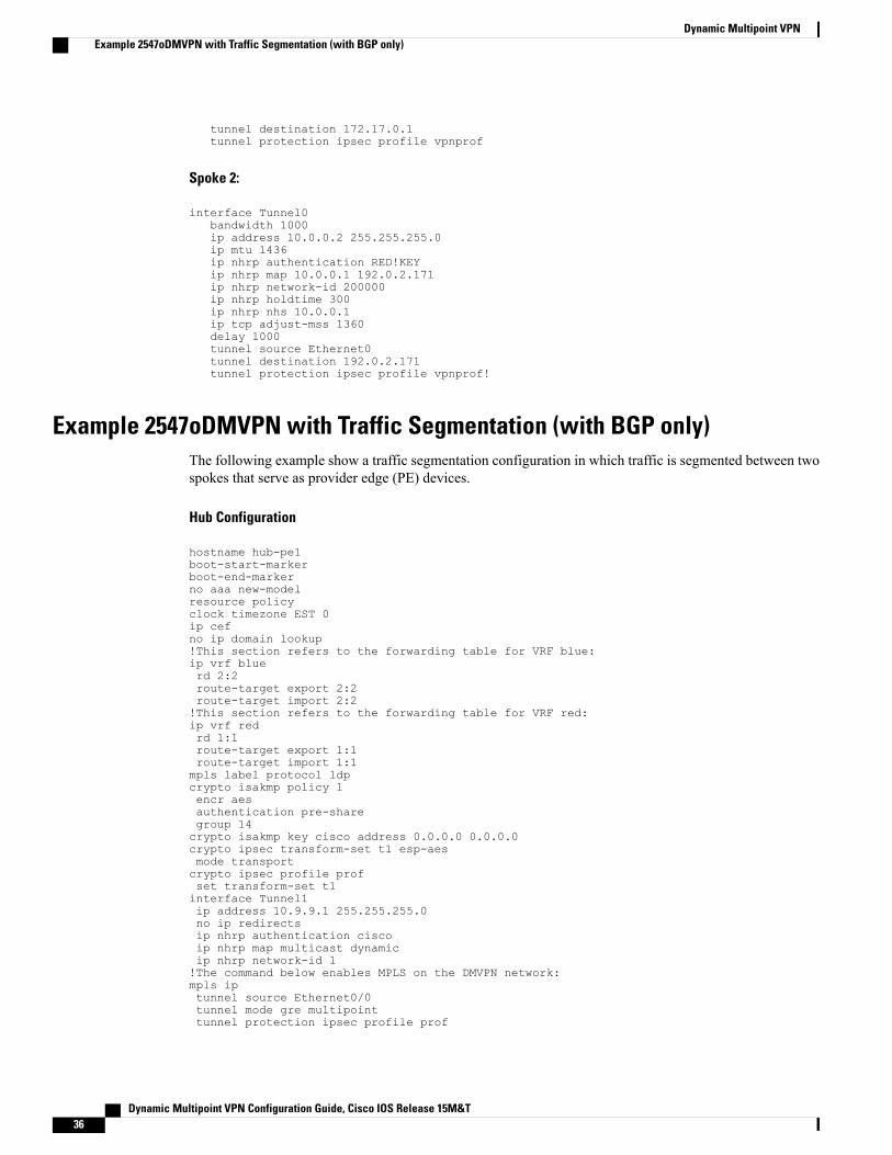
tunnel destination 172.17.0.1tunnel protection ipsec profile vpnprof
Spoke 2:
interface Tunnel0bandwidth 1000ip address 10.0.0.2 255.255.255.0ip mtu 1436ip nhrp authentication RED!KEYip nhrp map 10.0.0.1 192.0.2.171ip nhrp network-id 200000ip nhrp holdtime 300ip nhrp nhs 10.0.0.1ip tcp adjust-mss 1360delay 1000tunnel source Ethernet0tunnel destination 192.0.2.171tunnel protection ipsec profile vpnprof!
Example 2547oDMVPN with Traffic Segmentation (with BGP only)The following example show a traffic segmentation configuration in which traffic is segmented between twospokes that serve as provider edge (PE) devices.
Hub Configuration
hostname hub-pe1boot-start-markerboot-end-markerno aaa new-modelresource policyclock timezone EST 0ip cefno ip domain lookup!This section refers to the forwarding table for VRF blue:ip vrf bluerd 2:2route-target export 2:2route-target import 2:2!This section refers to the forwarding table for VRF red:ip vrf redrd 1:1route-target export 1:1route-target import 1:1mpls label protocol ldpcrypto isakmp policy 1encr aesauthentication pre-sharegroup 14crypto isakmp key cisco address 0.0.0.0 0.0.0.0crypto ipsec transform-set t1 esp-aesmode transportcrypto ipsec profile profset transform-set t1interface Tunnel1ip address 10.9.9.1 255.255.255.0no ip redirectsip nhrp authentication ciscoip nhrp map multicast dynamicip nhrp network-id 1!The command below enables MPLS on the DMVPN network:mpls iptunnel source Ethernet0/0tunnel mode gre multipointtunnel protection ipsec profile prof
Dynamic Multipoint VPN Configuration Guide, Cisco IOS Release 15M&T36
Dynamic Multipoint VPNExample 2547oDMVPN with Traffic Segmentation (with BGP only)
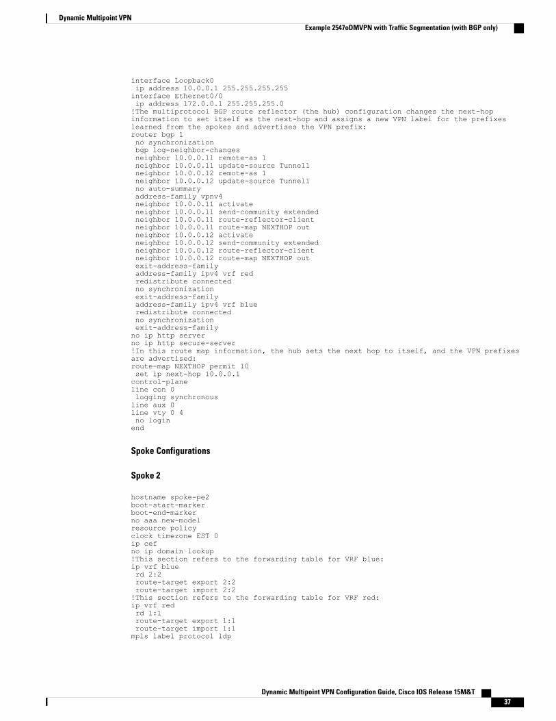
interface Loopback0ip address 10.0.0.1 255.255.255.255interface Ethernet0/0ip address 172.0.0.1 255.255.255.0!The multiprotocol BGP route reflector (the hub) configuration changes the next-hopinformation to set itself as the next-hop and assigns a new VPN label for the prefixeslearned from the spokes and advertises the VPN prefix:router bgp 1no synchronizationbgp log-neighbor-changesneighbor 10.0.0.11 remote-as 1neighbor 10.0.0.11 update-source Tunnel1neighbor 10.0.0.12 remote-as 1neighbor 10.0.0.12 update-source Tunnel1no auto-summaryaddress-family vpnv4neighbor 10.0.0.11 activateneighbor 10.0.0.11 send-community extendedneighbor 10.0.0.11 route-reflector-clientneighbor 10.0.0.11 route-map NEXTHOP outneighbor 10.0.0.12 activateneighbor 10.0.0.12 send-community extendedneighbor 10.0.0.12 route-reflector-clientneighbor 10.0.0.12 route-map NEXTHOP outexit-address-familyaddress-family ipv4 vrf redredistribute connectedno synchronizationexit-address-familyaddress-family ipv4 vrf blueredistribute connectedno synchronizationexit-address-familyno ip http serverno ip http secure-server!In this route map information, the hub sets the next hop to itself, and the VPN prefixesare advertised:route-map NEXTHOP permit 10set ip next-hop 10.0.0.1control-planeline con 0logging synchronousline aux 0line vty 0 4no loginend
Spoke Configurations
Spoke 2
hostname spoke-pe2boot-start-markerboot-end-markerno aaa new-modelresource policyclock timezone EST 0ip cefno ip domain lookup!This section refers to the forwarding table for VRF blue:ip vrf bluerd 2:2route-target export 2:2route-target import 2:2!This section refers to the forwarding table for VRF red:ip vrf redrd 1:1route-target export 1:1route-target import 1:1mpls label protocol ldp
Dynamic Multipoint VPN Configuration Guide, Cisco IOS Release 15M&T 37
Dynamic Multipoint VPNExample 2547oDMVPN with Traffic Segmentation (with BGP only)
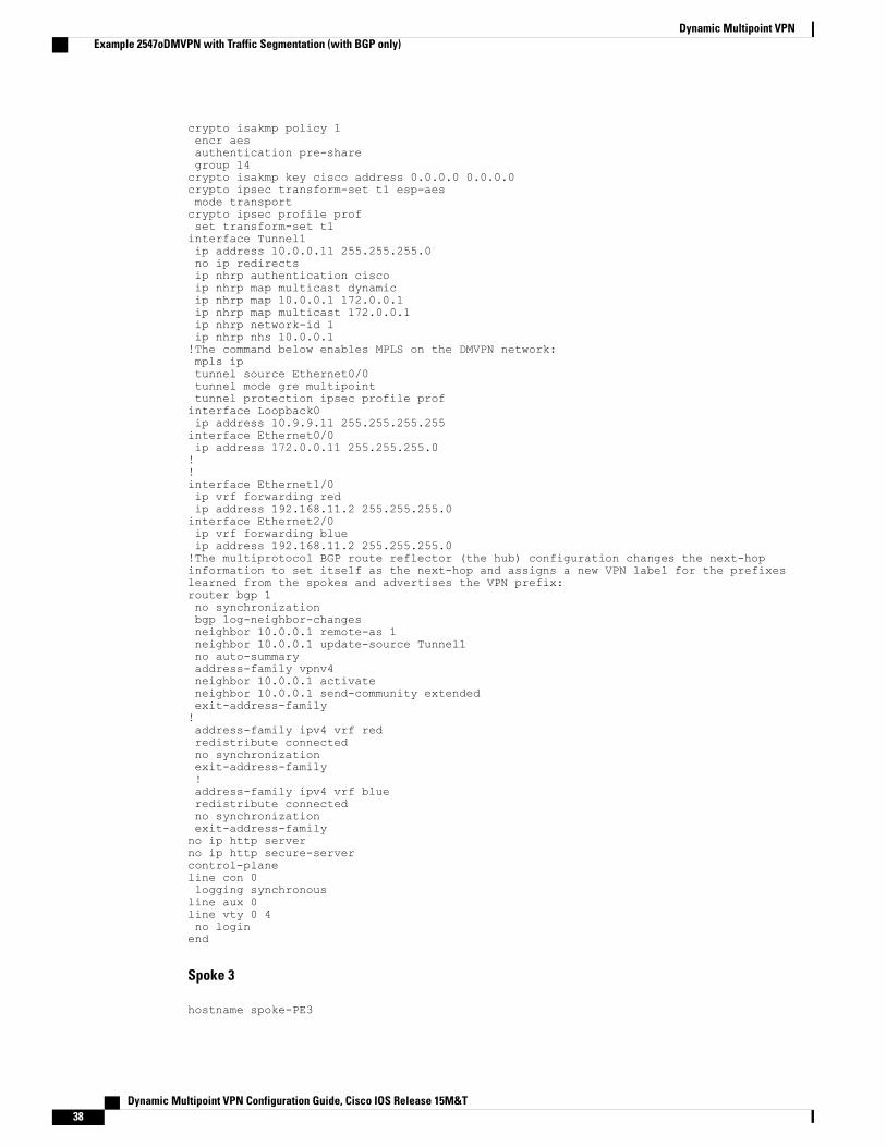
crypto isakmp policy 1encr aesauthentication pre-sharegroup 14crypto isakmp key cisco address 0.0.0.0 0.0.0.0crypto ipsec transform-set t1 esp-aesmode transportcrypto ipsec profile profset transform-set t1interface Tunnel1ip address 10.0.0.11 255.255.255.0no ip redirectsip nhrp authentication ciscoip nhrp map multicast dynamicip nhrp map 10.0.0.1 172.0.0.1ip nhrp map multicast 172.0.0.1ip nhrp network-id 1ip nhrp nhs 10.0.0.1!The command below enables MPLS on the DMVPN network:mpls iptunnel source Ethernet0/0tunnel mode gre multipointtunnel protection ipsec profile profinterface Loopback0ip address 10.9.9.11 255.255.255.255interface Ethernet0/0ip address 172.0.0.11 255.255.255.0!!interface Ethernet1/0ip vrf forwarding redip address 192.168.11.2 255.255.255.0interface Ethernet2/0ip vrf forwarding blueip address 192.168.11.2 255.255.255.0!The multiprotocol BGP route reflector (the hub) configuration changes the next-hopinformation to set itself as the next-hop and assigns a new VPN label for the prefixeslearned from the spokes and advertises the VPN prefix:router bgp 1no synchronizationbgp log-neighbor-changesneighbor 10.0.0.1 remote-as 1neighbor 10.0.0.1 update-source Tunnel1no auto-summaryaddress-family vpnv4neighbor 10.0.0.1 activateneighbor 10.0.0.1 send-community extendedexit-address-family!address-family ipv4 vrf redredistribute connectedno synchronizationexit-address-family!address-family ipv4 vrf blueredistribute connectedno synchronizationexit-address-familyno ip http serverno ip http secure-servercontrol-planeline con 0logging synchronousline aux 0line vty 0 4no loginend
Spoke 3
hostname spoke-PE3
Dynamic Multipoint VPN Configuration Guide, Cisco IOS Release 15M&T38
Dynamic Multipoint VPNExample 2547oDMVPN with Traffic Segmentation (with BGP only)
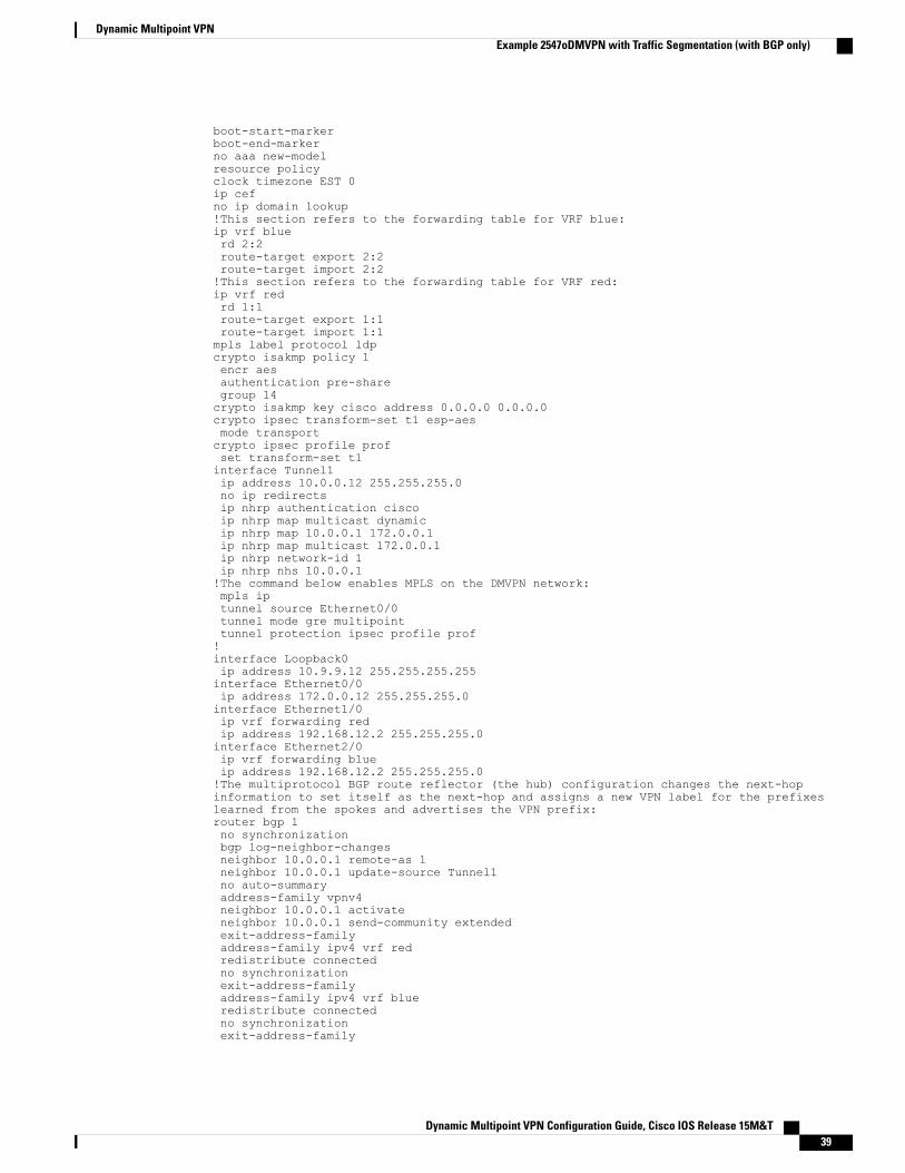
boot-start-markerboot-end-markerno aaa new-modelresource policyclock timezone EST 0ip cefno ip domain lookup!This section refers to the forwarding table for VRF blue:ip vrf bluerd 2:2route-target export 2:2route-target import 2:2!This section refers to the forwarding table for VRF red:ip vrf redrd 1:1route-target export 1:1route-target import 1:1mpls label protocol ldpcrypto isakmp policy 1encr aesauthentication pre-sharegroup 14crypto isakmp key cisco address 0.0.0.0 0.0.0.0crypto ipsec transform-set t1 esp-aesmode transportcrypto ipsec profile profset transform-set t1interface Tunnel1ip address 10.0.0.12 255.255.255.0no ip redirectsip nhrp authentication ciscoip nhrp map multicast dynamicip nhrp map 10.0.0.1 172.0.0.1ip nhrp map multicast 172.0.0.1ip nhrp network-id 1ip nhrp nhs 10.0.0.1!The command below enables MPLS on the DMVPN network:mpls iptunnel source Ethernet0/0tunnel mode gre multipointtunnel protection ipsec profile prof!interface Loopback0ip address 10.9.9.12 255.255.255.255interface Ethernet0/0ip address 172.0.0.12 255.255.255.0interface Ethernet1/0ip vrf forwarding redip address 192.168.12.2 255.255.255.0interface Ethernet2/0ip vrf forwarding blueip address 192.168.12.2 255.255.255.0!The multiprotocol BGP route reflector (the hub) configuration changes the next-hopinformation to set itself as the next-hop and assigns a new VPN label for the prefixeslearned from the spokes and advertises the VPN prefix:router bgp 1no synchronizationbgp log-neighbor-changesneighbor 10.0.0.1 remote-as 1neighbor 10.0.0.1 update-source Tunnel1no auto-summaryaddress-family vpnv4neighbor 10.0.0.1 activateneighbor 10.0.0.1 send-community extendedexit-address-familyaddress-family ipv4 vrf redredistribute connectedno synchronizationexit-address-familyaddress-family ipv4 vrf blueredistribute connectedno synchronizationexit-address-family
Dynamic Multipoint VPN Configuration Guide, Cisco IOS Release 15M&T 39
Dynamic Multipoint VPNExample 2547oDMVPN with Traffic Segmentation (with BGP only)
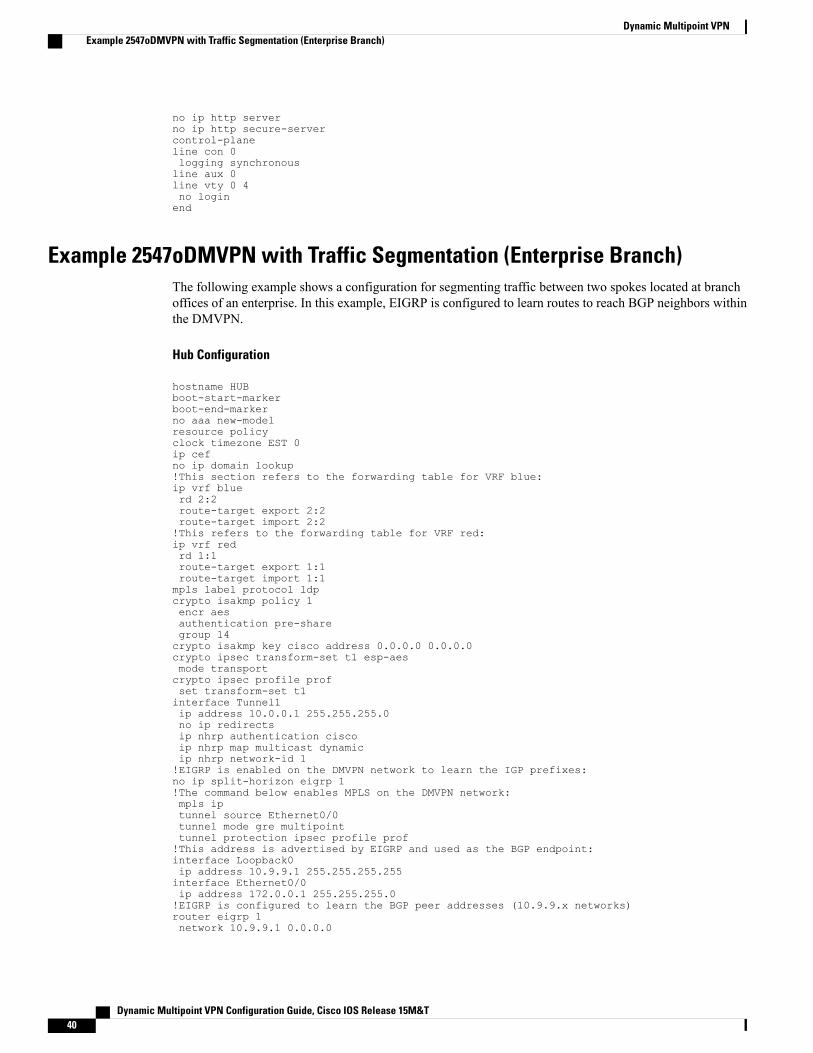
no ip http serverno ip http secure-servercontrol-planeline con 0logging synchronousline aux 0line vty 0 4no loginend
Example 2547oDMVPN with Traffic Segmentation (Enterprise Branch)The following example shows a configuration for segmenting traffic between two spokes located at branchoffices of an enterprise. In this example, EIGRP is configured to learn routes to reach BGP neighbors withinthe DMVPN.
Hub Configuration
hostname HUBboot-start-markerboot-end-markerno aaa new-modelresource policyclock timezone EST 0ip cefno ip domain lookup!This section refers to the forwarding table for VRF blue:ip vrf bluerd 2:2route-target export 2:2route-target import 2:2!This refers to the forwarding table for VRF red:ip vrf redrd 1:1route-target export 1:1route-target import 1:1mpls label protocol ldpcrypto isakmp policy 1encr aesauthentication pre-sharegroup 14crypto isakmp key cisco address 0.0.0.0 0.0.0.0crypto ipsec transform-set t1 esp-aesmode transportcrypto ipsec profile profset transform-set t1interface Tunnel1ip address 10.0.0.1 255.255.255.0no ip redirectsip nhrp authentication ciscoip nhrp map multicast dynamicip nhrp network-id 1!EIGRP is enabled on the DMVPN network to learn the IGP prefixes:no ip split-horizon eigrp 1!The command below enables MPLS on the DMVPN network:mpls iptunnel source Ethernet0/0tunnel mode gre multipointtunnel protection ipsec profile prof!This address is advertised by EIGRP and used as the BGP endpoint:interface Loopback0ip address 10.9.9.1 255.255.255.255interface Ethernet0/0ip address 172.0.0.1 255.255.255.0!EIGRP is configured to learn the BGP peer addresses (10.9.9.x networks)router eigrp 1network 10.9.9.1 0.0.0.0
Dynamic Multipoint VPN Configuration Guide, Cisco IOS Release 15M&T40
Dynamic Multipoint VPNExample 2547oDMVPN with Traffic Segmentation (Enterprise Branch)
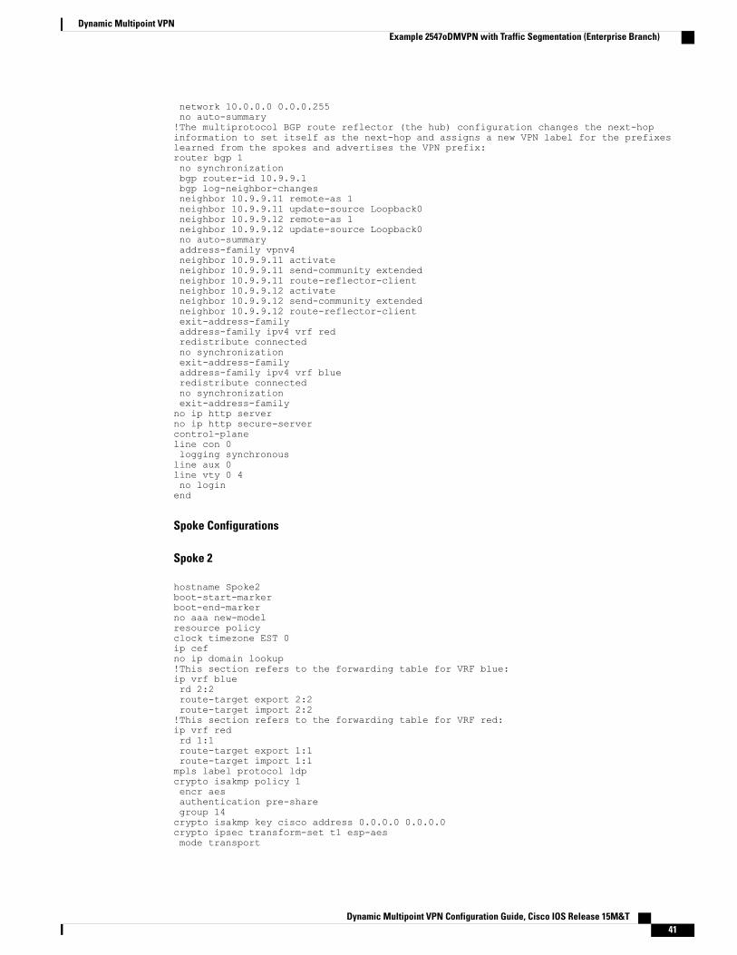
network 10.0.0.0 0.0.0.255no auto-summary!The multiprotocol BGP route reflector (the hub) configuration changes the next-hopinformation to set itself as the next-hop and assigns a new VPN label for the prefixeslearned from the spokes and advertises the VPN prefix:router bgp 1no synchronizationbgp router-id 10.9.9.1bgp log-neighbor-changesneighbor 10.9.9.11 remote-as 1neighbor 10.9.9.11 update-source Loopback0neighbor 10.9.9.12 remote-as 1neighbor 10.9.9.12 update-source Loopback0no auto-summaryaddress-family vpnv4neighbor 10.9.9.11 activateneighbor 10.9.9.11 send-community extendedneighbor 10.9.9.11 route-reflector-clientneighbor 10.9.9.12 activateneighbor 10.9.9.12 send-community extendedneighbor 10.9.9.12 route-reflector-clientexit-address-familyaddress-family ipv4 vrf redredistribute connectedno synchronizationexit-address-familyaddress-family ipv4 vrf blueredistribute connectedno synchronizationexit-address-familyno ip http serverno ip http secure-servercontrol-planeline con 0logging synchronousline aux 0line vty 0 4no loginend
Spoke Configurations
Spoke 2
hostname Spoke2boot-start-markerboot-end-markerno aaa new-modelresource policyclock timezone EST 0ip cefno ip domain lookup!This section refers to the forwarding table for VRF blue:ip vrf bluerd 2:2route-target export 2:2route-target import 2:2!This section refers to the forwarding table for VRF red:ip vrf redrd 1:1route-target export 1:1route-target import 1:1mpls label protocol ldpcrypto isakmp policy 1encr aesauthentication pre-sharegroup 14crypto isakmp key cisco address 0.0.0.0 0.0.0.0crypto ipsec transform-set t1 esp-aesmode transport
Dynamic Multipoint VPN Configuration Guide, Cisco IOS Release 15M&T 41
Dynamic Multipoint VPNExample 2547oDMVPN with Traffic Segmentation (Enterprise Branch)
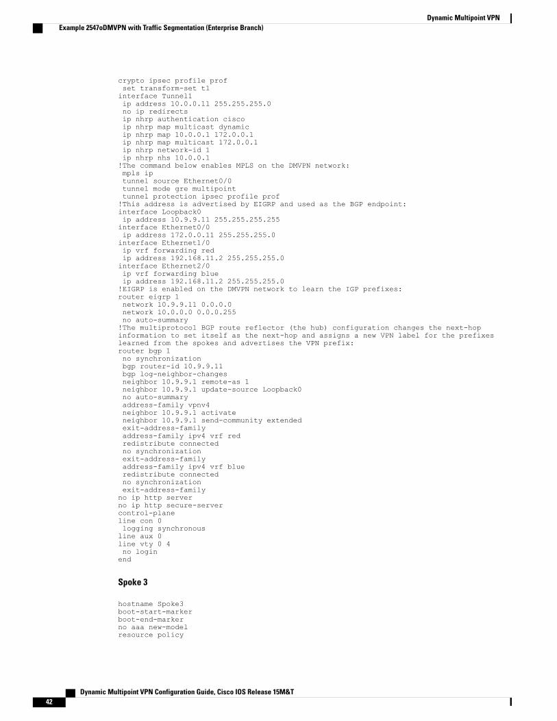
crypto ipsec profile profset transform-set t1interface Tunnel1ip address 10.0.0.11 255.255.255.0no ip redirectsip nhrp authentication ciscoip nhrp map multicast dynamicip nhrp map 10.0.0.1 172.0.0.1ip nhrp map multicast 172.0.0.1ip nhrp network-id 1ip nhrp nhs 10.0.0.1!The command below enables MPLS on the DMVPN network:mpls iptunnel source Ethernet0/0tunnel mode gre multipointtunnel protection ipsec profile prof!This address is advertised by EIGRP and used as the BGP endpoint:interface Loopback0ip address 10.9.9.11 255.255.255.255interface Ethernet0/0ip address 172.0.0.11 255.255.255.0interface Ethernet1/0ip vrf forwarding redip address 192.168.11.2 255.255.255.0interface Ethernet2/0ip vrf forwarding blueip address 192.168.11.2 255.255.255.0!EIGRP is enabled on the DMVPN network to learn the IGP prefixes:router eigrp 1network 10.9.9.11 0.0.0.0network 10.0.0.0 0.0.0.255no auto-summary!The multiprotocol BGP route reflector (the hub) configuration changes the next-hopinformation to set itself as the next-hop and assigns a new VPN label for the prefixeslearned from the spokes and advertises the VPN prefix:router bgp 1no synchronizationbgp router-id 10.9.9.11bgp log-neighbor-changesneighbor 10.9.9.1 remote-as 1neighbor 10.9.9.1 update-source Loopback0no auto-summaryaddress-family vpnv4neighbor 10.9.9.1 activateneighbor 10.9.9.1 send-community extendedexit-address-familyaddress-family ipv4 vrf redredistribute connectedno synchronizationexit-address-familyaddress-family ipv4 vrf blueredistribute connectedno synchronizationexit-address-familyno ip http serverno ip http secure-servercontrol-planeline con 0logging synchronousline aux 0line vty 0 4no loginend
Spoke 3
hostname Spoke3boot-start-markerboot-end-markerno aaa new-modelresource policy
Dynamic Multipoint VPN Configuration Guide, Cisco IOS Release 15M&T42
Dynamic Multipoint VPNExample 2547oDMVPN with Traffic Segmentation (Enterprise Branch)
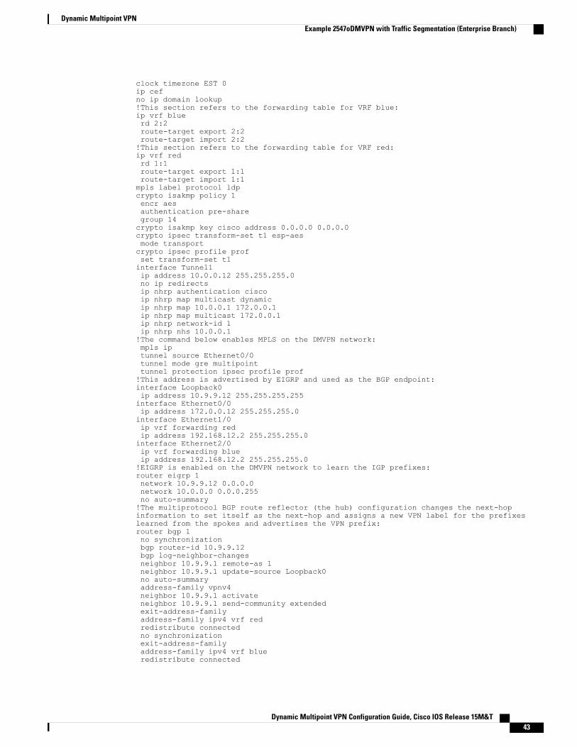
clock timezone EST 0ip cefno ip domain lookup!This section refers to the forwarding table for VRF blue:ip vrf bluerd 2:2route-target export 2:2route-target import 2:2!This section refers to the forwarding table for VRF red:ip vrf redrd 1:1route-target export 1:1route-target import 1:1mpls label protocol ldpcrypto isakmp policy 1encr aesauthentication pre-sharegroup 14crypto isakmp key cisco address 0.0.0.0 0.0.0.0crypto ipsec transform-set t1 esp-aesmode transportcrypto ipsec profile profset transform-set t1interface Tunnel1ip address 10.0.0.12 255.255.255.0no ip redirectsip nhrp authentication ciscoip nhrp map multicast dynamicip nhrp map 10.0.0.1 172.0.0.1ip nhrp map multicast 172.0.0.1ip nhrp network-id 1ip nhrp nhs 10.0.0.1!The command below enables MPLS on the DMVPN network:mpls iptunnel source Ethernet0/0tunnel mode gre multipointtunnel protection ipsec profile prof!This address is advertised by EIGRP and used as the BGP endpoint:interface Loopback0ip address 10.9.9.12 255.255.255.255interface Ethernet0/0ip address 172.0.0.12 255.255.255.0interface Ethernet1/0ip vrf forwarding redip address 192.168.12.2 255.255.255.0interface Ethernet2/0ip vrf forwarding blueip address 192.168.12.2 255.255.255.0!EIGRP is enabled on the DMVPN network to learn the IGP prefixes:router eigrp 1network 10.9.9.12 0.0.0.0network 10.0.0.0 0.0.0.255no auto-summary!The multiprotocol BGP route reflector (the hub) configuration changes the next-hopinformation to set itself as the next-hop and assigns a new VPN label for the prefixeslearned from the spokes and advertises the VPN prefix:router bgp 1no synchronizationbgp router-id 10.9.9.12bgp log-neighbor-changesneighbor 10.9.9.1 remote-as 1neighbor 10.9.9.1 update-source Loopback0no auto-summaryaddress-family vpnv4neighbor 10.9.9.1 activateneighbor 10.9.9.1 send-community extendedexit-address-familyaddress-family ipv4 vrf redredistribute connectedno synchronizationexit-address-familyaddress-family ipv4 vrf blueredistribute connected
Dynamic Multipoint VPN Configuration Guide, Cisco IOS Release 15M&T 43
Dynamic Multipoint VPNExample 2547oDMVPN with Traffic Segmentation (Enterprise Branch)
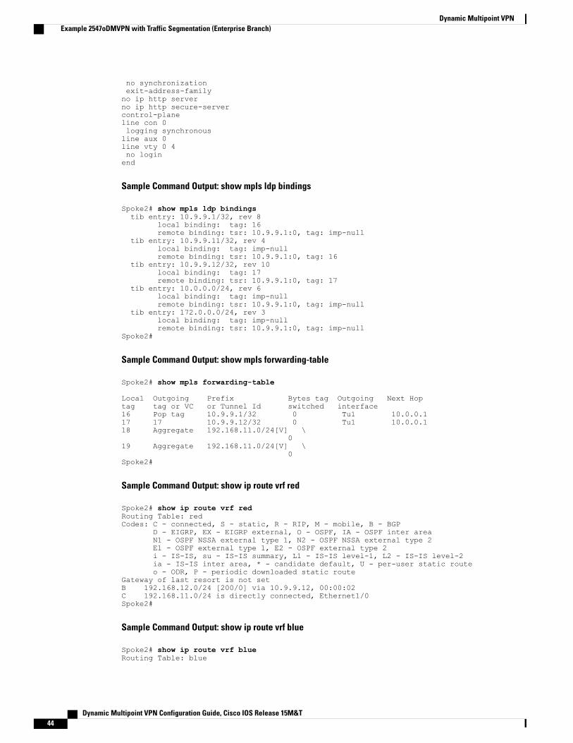
no synchronizationexit-address-familyno ip http serverno ip http secure-servercontrol-planeline con 0logging synchronousline aux 0line vty 0 4no loginend
Sample Command Output: show mpls ldp bindings
Spoke2# show mpls ldp bindingstib entry: 10.9.9.1/32, rev 8
local binding: tag: 16remote binding: tsr: 10.9.9.1:0, tag: imp-null
tib entry: 10.9.9.11/32, rev 4local binding: tag: imp-nullremote binding: tsr: 10.9.9.1:0, tag: 16
tib entry: 10.9.9.12/32, rev 10local binding: tag: 17remote binding: tsr: 10.9.9.1:0, tag: 17
tib entry: 10.0.0.0/24, rev 6local binding: tag: imp-nullremote binding: tsr: 10.9.9.1:0, tag: imp-null
tib entry: 172.0.0.0/24, rev 3local binding: tag: imp-nullremote binding: tsr: 10.9.9.1:0, tag: imp-null
Spoke2#
Sample Command Output: show mpls forwarding-table
Spoke2# show mpls forwarding-table
Local Outgoing Prefix Bytes tag Outgoing Next Hoptag tag or VC or Tunnel Id switched interface16 Pop tag 10.9.9.1/32 0 Tu1 10.0.0.117 17 10.9.9.12/32 0 Tu1 10.0.0.118 Aggregate 192.168.11.0/24[V] \
019 Aggregate 192.168.11.0/24[V] \
0Spoke2#
Sample Command Output: show ip route vrf red
Spoke2# show ip route vrf redRouting Table: redCodes: C - connected, S - static, R - RIP, M - mobile, B - BGP
D - EIGRP, EX - EIGRP external, O - OSPF, IA - OSPF inter areaN1 - OSPF NSSA external type 1, N2 - OSPF NSSA external type 2E1 - OSPF external type 1, E2 - OSPF external type 2i - IS-IS, su - IS-IS summary, L1 - IS-IS level-1, L2 - IS-IS level-2ia - IS-IS inter area, * - candidate default, U - per-user static routeo - ODR, P - periodic downloaded static route
Gateway of last resort is not setB 192.168.12.0/24 [200/0] via 10.9.9.12, 00:00:02C 192.168.11.0/24 is directly connected, Ethernet1/0Spoke2#
Sample Command Output: show ip route vrf blue
Spoke2# show ip route vrf blueRouting Table: blue
Dynamic Multipoint VPN Configuration Guide, Cisco IOS Release 15M&T44
Dynamic Multipoint VPNExample 2547oDMVPN with Traffic Segmentation (Enterprise Branch)
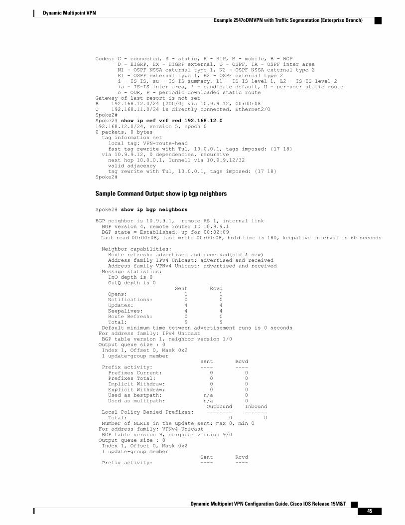
Codes: C - connected, S - static, R - RIP, M - mobile, B - BGPD - EIGRP, EX - EIGRP external, O - OSPF, IA - OSPF inter areaN1 - OSPF NSSA external type 1, N2 - OSPF NSSA external type 2E1 - OSPF external type 1, E2 - OSPF external type 2i - IS-IS, su - IS-IS summary, L1 - IS-IS level-1, L2 - IS-IS level-2ia - IS-IS inter area, * - candidate default, U - per-user static routeo - ODR, P - periodic downloaded static route
Gateway of last resort is not setB 192.168.12.0/24 [200/0] via 10.9.9.12, 00:00:08C 192.168.11.0/24 is directly connected, Ethernet2/0Spoke2#Spoke2# show ip cef vrf red 192.168.12.0192.168.12.0/24, version 5, epoch 00 packets, 0 bytestag information setlocal tag: VPN-route-headfast tag rewrite with Tu1, 10.0.0.1, tags imposed: {17 18}
via 10.9.9.12, 0 dependencies, recursivenext hop 10.0.0.1, Tunnel1 via 10.9.9.12/32valid adjacencytag rewrite with Tu1, 10.0.0.1, tags imposed: {17 18}
Spoke2#
Sample Command Output: show ip bgp neighbors
Spoke2# show ip bgp neighbors
BGP neighbor is 10.9.9.1, remote AS 1, internal linkBGP version 4, remote router ID 10.9.9.1BGP state = Established, up for 00:02:09Last read 00:00:08, last write 00:00:08, hold time is 180, keepalive interval is 60 seconds
Neighbor capabilities:Route refresh: advertised and received(old & new)Address family IPv4 Unicast: advertised and receivedAddress family VPNv4 Unicast: advertised and received
Message statistics:InQ depth is 0OutQ depth is 0
Sent RcvdOpens: 1 1Notifications: 0 0Updates: 4 4Keepalives: 4 4Route Refresh: 0 0Total: 9 9
Default minimum time between advertisement runs is 0 secondsFor address family: IPv4 UnicastBGP table version 1, neighbor version 1/0Output queue size : 0Index 1, Offset 0, Mask 0x21 update-group member
Sent RcvdPrefix activity: ---- ----Prefixes Current: 0 0Prefixes Total: 0 0Implicit Withdraw: 0 0Explicit Withdraw: 0 0Used as bestpath: n/a 0Used as multipath: n/a 0
Outbound InboundLocal Policy Denied Prefixes: -------- -------Total: 0 0
Number of NLRIs in the update sent: max 0, min 0For address family: VPNv4 UnicastBGP table version 9, neighbor version 9/0Output queue size : 0Index 1, Offset 0, Mask 0x21 update-group member
Sent RcvdPrefix activity: ---- ----
Dynamic Multipoint VPN Configuration Guide, Cisco IOS Release 15M&T 45
Dynamic Multipoint VPNExample 2547oDMVPN with Traffic Segmentation (Enterprise Branch)
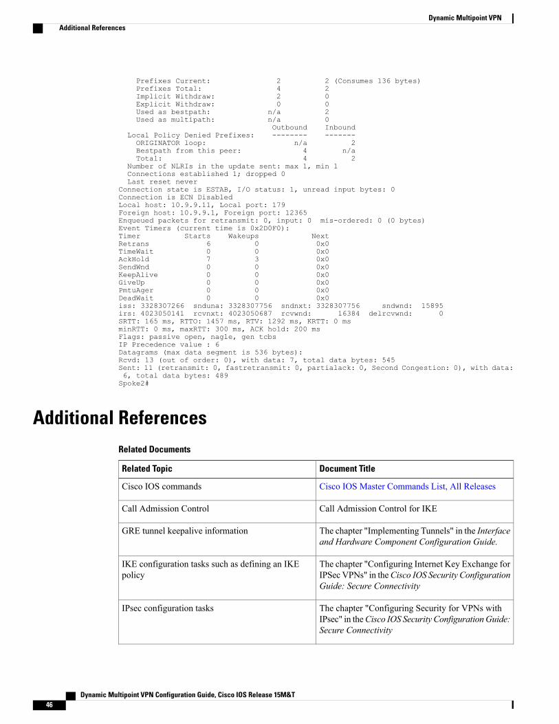
Prefixes Current: 2 2 (Consumes 136 bytes)Prefixes Total: 4 2Implicit Withdraw: 2 0Explicit Withdraw: 0 0Used as bestpath: n/a 2Used as multipath: n/a 0
Outbound InboundLocal Policy Denied Prefixes: -------- -------ORIGINATOR loop: n/a 2Bestpath from this peer: 4 n/aTotal: 4 2
Number of NLRIs in the update sent: max 1, min 1Connections established 1; dropped 0Last reset never
Connection state is ESTAB, I/O status: 1, unread input bytes: 0Connection is ECN DisabledLocal host: 10.9.9.11, Local port: 179Foreign host: 10.9.9.1, Foreign port: 12365Enqueued packets for retransmit: 0, input: 0 mis-ordered: 0 (0 bytes)Event Timers (current time is 0x2D0F0):Timer Starts Wakeups NextRetrans 6 0 0x0TimeWait 0 0 0x0AckHold 7 3 0x0SendWnd 0 0 0x0KeepAlive 0 0 0x0GiveUp 0 0 0x0PmtuAger 0 0 0x0DeadWait 0 0 0x0iss: 3328307266 snduna: 3328307756 sndnxt: 3328307756 sndwnd: 15895irs: 4023050141 rcvnxt: 4023050687 rcvwnd: 16384 delrcvwnd: 0SRTT: 165 ms, RTTO: 1457 ms, RTV: 1292 ms, KRTT: 0 msminRTT: 0 ms, maxRTT: 300 ms, ACK hold: 200 msFlags: passive open, nagle, gen tcbsIP Precedence value : 6Datagrams (max data segment is 536 bytes):Rcvd: 13 (out of order: 0), with data: 7, total data bytes: 545Sent: 11 (retransmit: 0, fastretransmit: 0, partialack: 0, Second Congestion: 0), with data:6, total data bytes: 489Spoke2#
Additional ReferencesRelated Documents
Document TitleRelated Topic
Cisco IOS Master Commands List, All ReleasesCisco IOS commands
Call Admission Control for IKECall Admission Control
The chapter "Implementing Tunnels" in the Interfaceand Hardware Component Configuration Guide.
GRE tunnel keepalive information
The chapter "Configuring Internet Key Exchange forIPSec VPNs" in theCisco IOS Security ConfigurationGuide: Secure Connectivity
IKE configuration tasks such as defining an IKEpolicy
The chapter "Configuring Security for VPNs withIPsec" in theCisco IOS Security ConfigurationGuide:Secure Connectivity
IPsec configuration tasks
Dynamic Multipoint VPN Configuration Guide, Cisco IOS Release 15M&T46
Dynamic Multipoint VPNAdditional References
Document TitleRelated Topic
The chapter "VRF-Aware IPsec" in the Cisco IOSSecurity Configuration Guide: Secure Connectivity
Configuring VRF-Aware IPsec
The chapter "Configuring Multiprotocol LabelSwitching" in the Cisco IOS Multiprotocol LabelSwitching Configuration Guide
Configuring MPLS
The chapter "Cisco BGPOverview" in theCisco IOSIP Routing: BGP Protocols Configuration Guide
Configuring BGP
System Message GuideSystem messages
"Certificate to ISAKMP Profile Mapping" chapter inthe Cisco IOS Security Configuration Guide: SecureConnectivity
Defining and configuring ISAKMP profiles
IPv6 Configuration GuideImplementing Dynamic Multipoint VPN for IPv6
Next Generation EncryptionRecommended cryptographic algorithms
Standards
TitleStandards
--None
MIBs
MIBs LinkMIBs
To locate and downloadMIBs for selected platforms,Cisco software releases, and feature sets, use CiscoMIB Locator found at the following URL:
http://www.cisco.com/go/mibs
None
RFCs
TitleRFCs
BGP/MPLS VPNsRFC 2547
Dynamic Multipoint VPN Configuration Guide, Cisco IOS Release 15M&T 47
Dynamic Multipoint VPNAdditional References
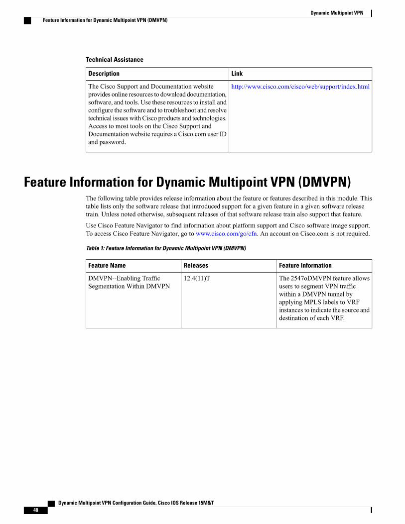
Technical Assistance
LinkDescription
http://www.cisco.com/cisco/web/support/index.htmlThe Cisco Support and Documentation websiteprovides online resources to download documentation,software, and tools. Use these resources to install andconfigure the software and to troubleshoot and resolvetechnical issues with Cisco products and technologies.Access to most tools on the Cisco Support andDocumentation website requires a Cisco.com user IDand password.
Feature Information for Dynamic Multipoint VPN (DMVPN)The following table provides release information about the feature or features described in this module. Thistable lists only the software release that introduced support for a given feature in a given software releasetrain. Unless noted otherwise, subsequent releases of that software release train also support that feature.
Use Cisco Feature Navigator to find information about platform support and Cisco software image support.To access Cisco Feature Navigator, go to www.cisco.com/go/cfn. An account on Cisco.com is not required.
Table 1: Feature Information for Dynamic Multipoint VPN (DMVPN)
Feature InformationReleasesFeature Name
The 2547oDMVPN feature allowsusers to segment VPN trafficwithin a DMVPN tunnel byapplying MPLS labels to VRFinstances to indicate the source anddestination of each VRF.
12.4(11)TDMVPN--Enabling TrafficSegmentation Within DMVPN
Dynamic Multipoint VPN Configuration Guide, Cisco IOS Release 15M&T48
Dynamic Multipoint VPNFeature Information for Dynamic Multipoint VPN (DMVPN)
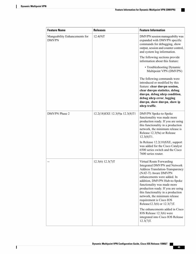
Feature InformationReleasesFeature Name
DMVPN sessionmanageabiltywasexpanded with DMVPN specificcommands for debugging, showoutput, session and counter control,and system log information.
The following sections provideinformation about this feature:
• Troubleshooting DynamicMultipoint VPN (DMVPN)
The following commands wereintroduced or modified by thisfeature: clear dmvpn session,clear dmvpn statistics, debugdmvpn, debug nhrp condition,debug nhrp error, loggingdmvpn, show dmvpn, show ipnhrp traffic.
12.4(9)TMangeability Enhancements forDMVPN
DMVPN Spoke-to-Spokefunctionality was made moreproduction ready. If you are usingthis functionality in a productionnetwork, the minimum release isRelease 12.3(9a) or Release12.3(8)T1.
In Release 12.2(18)SXE, supportwas added for the Cisco Catalyst6500 series switch and the Cisco7600 series router.
12.2(18)SXE 12.3(9)a 12.3(8)T1DMVPN Phase 2
Virtual Route ForwardingIntegrated DMVPN and NetworkAddress Translation-Transparency(NAT-T) Aware DMVPNenhancements were added. Inaddition, DMVPN Hub-to-Spokefunctionality was made moreproduction ready. If you are usingthis functionality in a productionnetwork, the minimum releaserequirement is Cisco IOSRelease12.3(6) or 12.3(7)T.
The enhancements added in CiscoIOS Release 12.3(6) wereintegrated into Cisco IOS Release12.3(7)T.
12.3(6) 12.3(7)T--
Dynamic Multipoint VPN Configuration Guide, Cisco IOS Release 15M&T 49
Dynamic Multipoint VPNFeature Information for Dynamic Multipoint VPN (DMVPN)
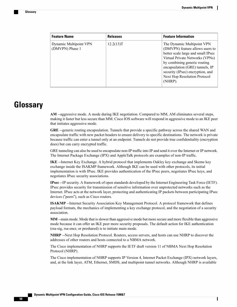
Feature InformationReleasesFeature Name
The Dynamic Multipoint VPN(DMVPN) feature allows users tobetter scale large and small IPsecVirtual Private Networks (VPNs)by combining generic routingencapsulation (GRE) tunnels, IPsecurity (IPsec) encryption, andNext Hop Resolution Protocol(NHRP).
12.2(13)TDynamic Multipoint VPN(DMVPN) Phase 1
GlossaryAM --aggressive mode. A mode during IKE negotiation. Compared to MM, AM eliminates several steps,making it faster but less secure than MM. Cisco IOS software will respond in aggressive mode to an IKE peerthat initiates aggressive mode.
GRE --generic routing encapsulation. Tunnels that provide a specific pathway across the shared WAN andencapsulate traffic with new packet headers to ensure delivery to specific destinations. The network is privatebecause traffic can enter a tunnel only at an endpoint. Tunnels do not provide true confidentiality (encryptiondoes) but can carry encrypted traffic.
GRE tunneling can also be used to encapsulate non-IP traffic into IP and send it over the Internet or IP network.The Internet Package Exchange (IPX) and AppleTalk protocols are examples of non-IP traffic.
IKE --Internet Key Exchange. A hybrid protocol that implements Oakley key exchange and Skeme keyexchange inside the ISAKMP framework. Although IKE can be used with other protocols, its initialimplementation is with IPsec. IKE provides authentication of the IPsec peers, negotiates IPsec keys, andnegotiates IPsec security associations.
IPsec --IP security. A framework of open standards developed by the Internet Engineering Task Force (IETF).IPsec provides security for transmission of sensitive information over unprotected networks such as theInternet. IPsec acts at the network layer, protecting and authenticating IP packets between participating IPsecdevices (“peers”), such as Cisco routers.ISAKMP --Internet Security Association Key Management Protocol. A protocol framework that definespayload formats, the mechanics of implementing a key exchange protocol, and the negotiation of a securityassociation.
MM --mainmode.Mode that is slower than aggressivemode but more secure andmore flexible than aggressivemode because it can offer an IKE peer more security proposals. The default action for IKE authentication(rsa-sig, rsa-encr, or preshared) is to initiate main mode.
NHRP --Next Hop Resolution Protocol. Routers, access servers, and hosts can use NHRP to discover theaddresses of other routers and hosts connected to a NBMA network.
The Cisco implementation of NHRP supports the IETF draft version 11 of NBMA Next Hop ResolutionProtocol (NHRP).
The Cisco implementation of NHRP supports IP Version 4, Internet Packet Exchange (IPX) network layers,and, at the link layer, ATM, Ethernet, SMDS, and multipoint tunnel networks. Although NHRP is available
Dynamic Multipoint VPN Configuration Guide, Cisco IOS Release 15M&T50
Dynamic Multipoint VPNGlossary
on Ethernet, NHRP need not be implemented over Ethernet media because Ethernet is capable of broadcasting.Ethernet support is unnecessary (and not provided) for IPX.
PFS --Perfect Forward Secrecy. A cryptographic characteristic associated with a derived shared secret value.With PFS, if one key is compromised, previous and subsequent keys are not compromised, because subsequentkeys are not derived from previous keys.
SA --security association. Describes how two or more entities will utilize security services to communicatesecurely. For example, an IPsec SA defines the encryption algorithm (if used), the authentication algorithm,and the shared session key to be used during the IPsec connection.
Both IPsec and IKE require and use SAs to identify the parameters of their connections. IKE can negotiateand establish its own SA. The IPsec SA is established either by IKE or by manual user configuration.
transform --The list of operations done on a dataflow to provide data authentication, data confidentiality,and data compression. One example of a transform is ESP with the 256-bit AES encryption algorithm andthe AH protocol with the HMAC-SHA authentication algorithm.
VPN --Virtual Private Network. A framework that consists of multiple peers transmitting private data securelyto one another over an otherwise public infrastructure. In this framework, inbound and outbound networktraffic is protected using protocols that tunnel and encrypt all data. This framework permits networks to extendbeyond their local topology, while remote users are provided with the appearance and functionality of a directnetwork connection.
Dynamic Multipoint VPN Configuration Guide, Cisco IOS Release 15M&T 51
Dynamic Multipoint VPNGlossary

Dynamic Multipoint VPN Configuration Guide, Cisco IOS Release 15M&T52
Dynamic Multipoint VPNGlossary
Related Documents