Americas Headquarters Cisco Systems, Inc. 170 West Tasman Drive San Jose, CA 95134-1706 USA http://www.cisco.com Tel: 408 526-4000 800 553-NETS (6387) Fax: 408 527-0883 Dynamic Multipoint VPN (DMVPN) Design Guide (Version 1.1) Cisco Validated Design July 10, 2008 Customer Order Number: Text Part Number: OL-9024-01

Welcome message from author
This document is posted to help you gain knowledge. Please leave a comment to let me know what you think about it! Share it to your friends and learn new things together.
Transcript

Dynamic Multipoint VPN (DMVPN) Design Guide (Version 1.1)Cisco Validated Design
July 10, 2008
Americas HeadquartersCisco Systems, Inc.170 West Tasman DriveSan Jose, CA 95134-1706 USAhttp://www.cisco.comTel: 408 526-4000
800 553-NETS (6387)Fax: 408 527-0883
Customer Order Number: Text Part Number: OL-9024-01

Cisco Validated DesignThe Cisco Validated Design Program consists of systems and solutions designed, tested, and documented to facilitate faster, more reliable, and more predictable customer deployments. For more information visit www.cisco.com/go/validateddesigns.
ALL DESIGNS, SPECIFICATIONS, STATEMENTS, INFORMATION, AND RECOMMENDATIONS (COLLECTIVELY, "DESIGNS") IN THIS MANUAL ARE PRESENTED "AS IS," WITH ALL FAULTS. CISCO AND ITS SUPPLIERS DISCLAIM ALL WARRANTIES, INCLUDING, WITHOUT LIMITATION, THE WARRANTY OF MERCHANTABILITY, FITNESS FOR A PARTICULAR PURPOSE AND NONINFRINGEMENT OR ARISING FROM A COURSE OF DEALING, USAGE, OR TRADE PRACTICE. IN NO EVENT SHALL CISCO OR ITS SUPPLIERS BE LIABLE FOR ANY INDIRECT, SPECIAL, CONSEQUENTIAL, OR INCIDENTAL DAMAGES, INCLUDING, WITHOUT LIMITATION, LOST PROFITS OR LOSS OR DAMAGE TO DATA ARISING OUT OF THE USE OR INABILITY TO USE THE DESIGNS, EVEN IF CISCO OR ITS SUPPLIERS HAVE BEEN ADVISED OF THE POSSIBILITY OF SUCH DAMAGES.
THE DESIGNS ARE SUBJECT TO CHANGE WITHOUT NOTICE. USERS ARE SOLELY RESPONSIBLE FOR THEIR APPLICATION OF THE DESIGNS. THE DESIGNS DO NOT CONSTITUTE THE TECHNICAL OR OTHER PROFESSIONAL ADVICE OF CISCO, ITS SUPPLIERS OR PARTNERS. USERS SHOULD CONSULT THEIR OWN TECHNICAL ADVISORS BEFORE IMPLEMENTING THE DESIGNS. RESULTS MAY VARY DEPENDING ON FACTORS NOT TESTED BY CISCO.
CCVP, the Cisco logo, and Welcome to the Human Network are trademarks of Cisco Systems, Inc.; Changing the Way We Work, Live, Play, and Learn is a service mark of Cisco Systems, Inc.; and Access Registrar, Aironet, Catalyst, CCDA, CCDP, CCIE, CCIP, CCNA, CCNP, CCSP, Cisco, the Cisco Certified Internetwork Expert logo, Cisco IOS, Cisco Press, Cisco Systems, Cisco Systems Capital, the Cisco Systems logo, Cisco Unity, Enterprise/Solver, EtherChannel, EtherFast, EtherSwitch, Fast Step, Follow Me Browsing, FormShare, GigaDrive, HomeLink, Internet Quotient, IOS, iPhone, IP/TV, iQ Expertise, the iQ logo, iQ Net Readiness Scorecard, iQuick Study, LightStream, Linksys, MeetingPlace, MGX, Networkers, Networking Academy, Network Registrar, PIX, ProConnect, ScriptShare, SMARTnet, StackWise, The Fastest Way to Increase Your Internet Quotient, and TransPath are registered trademarks of Cisco Systems, Inc. and/or its affiliates in the United States and certain other countries.
All other trademarks mentioned in this document or Website are the property of their respective owners. The use of the word partner does not imply a partnership relationship between Cisco and any other company. (0711R)
Dynamic Multipoint VPN (DMVPN) Design Guide (Version 1.1) © 2007 Cisco Systems, Inc. All rights reserved.

OL-9024-01
C O N T E N T S
Introduction i-i
Audience i-ii
Updates to Version 1.1 i-ii
Scope of Work i-ii
Document Objectives i-ii
Document Organization i-iii
C H A P T E R 1 DMVPN Design Overview 1-1
Overview 1-1
Starting Assumptions 1-2
Design Components 1-2
Design Topologies 1-3
Dual DMVPN Cloud Topology 1-4
Dual DMVPN Cloud Topology—Hub-and-Spoke Deployment Model 1-4
Dual DMVPN Cloud Topology—Spoke-to-Spoke Deployment Model 1-7
Single DMVPN Cloud Topology 1-9
Best Practices and Known Limitations 1-10
Best Practices Summary for Hub-and-Spoke Deployment Model 1-10
Known Limitations Summary for Hub-and-Spoke Deployment Model 1-12
Best Practices Summary for Spoke-to-Spoke Deployment Model 1-12
Known Limitations Summary for Spoke-to-Spoke Deployment Model 1-13
C H A P T E R 2 DMVPN Design and Implementation 2-1
Design Considerations 2-1
Topology 2-1
Dual DMVPN Hub-and-Spoke 2-2
Dual DMVPN Cloud Topology—Hub-and-Spoke Deployment Model (Single Tier Headend Architecture) 2-2
Dual DMVPN Cloud Topology—Hub-and-Spoke Deployment Model (Dual Tier Headend Architecture) 2-3
Dual DMVPN Cloud Topology—Spoke-to-Spoke Deployment Model 2-4
Dual DMVPN Cloud Topology—Spoke-to-Spoke Deployment Model (Single Tier Headend Architecture) 2-5
IP Addressing 2-5
iDynamic Multipoint VPN (DMVPN) 1.1 Design Guide
Contents
Generic Routing Encapsulation—p2p GRE and mGRE Interfaces 2-6
Next Hop Resolution Protocol 2-7
Tunnel Protection Mode 2-8
Using a Routing Protocol across the VPN 2-9
Route Propagation Strategy 2-9
Crypto Considerations 2-10
IKE Call Admission Control 2-10
Configuration and Implementation 2-11
ISAKMP Policy Configuration 2-11
IPsec Transform and Protocol Configuration 2-12
Tunnel Protection Configuration 2-13
Dynamic Crypto Map Configuration 2-13
Applying Crypto Maps 2-14
mGRE Configuration 2-15
Tunnel Interface Configuration—Hub-and-Spoke Only 2-15
Tunnel Interface Configuration—Dynamic Spoke-to-Spoke 2-15
NHRP Configuration 2-16
Routing Protocol Configuration 2-17
EIGRP Configuration 2-17
OSPF Configuration 2-18
RIPv2 Configuration 2-20
High Availability 2-21
Common Elements in all HA Headend Designs 2-21
Dual DMVPN Cloud Topology—Hub-and-Spoke Deployment Model 2-21
Hub-and-Spoke Deployment Model—Single Tier Headend Architecture 2-21
Hub-and-Spoke Deployment Model—Dual Tier Headend Architecture 2-22
Dual DMVPN Cloud Topology—Spoke-to-Spoke Deployment Model 2-23
QoS 2-25
QoS in a Hub-and-Spoke Deployment Model 2-25
QoS in a Spoke-to-Spoke Deployment Model 2-29
IP Multicast 2-29
Interactions with Other Networking Functions 2-31
Network Address Translation and Port Address Translation 2-31
Firewall Considerations 2-32
Headend or Branch 2-32
Crypto Access Check 2-32
Common Configuration Mistakes 2-32
Advertising Tunnel Endpoints in the Routing Protocol 2-33
IPsec Transform Set Matches 2-33
iiDynamic Multipoint VPN (DMVPN) 1.1 Design Guide
OL-9024-01

Contents
ISAKMP Policy Matching 2-33
C H A P T E R 3 Scalability Considerations 3-1
General Scalability Considerations 3-1
IPsec Encryption Throughput 3-1
Packets Per Second—Most Important Factor 3-2
Tunnel Quantity Affects Throughput 3-2
GRE Encapsulation Affects Throughput 3-2
Routing Protocols Affect CPU Overhead 3-3
Scalable Dual DMVPN Cloud Topology—Hub-and-Spoke Deployment Model 3-3
Headend Scalability 3-3
Tunnel Aggregation Scalability 3-3
Aggregation Scalability 3-3
Customer Requirement Aggregation Scalability Case Studies 3-3
Branch Office Scalability 3-7
Scalable Dual-DMVPN Cloud Topology—Spoke-to-Spoke Designs 3-7
Regional Spoke-to-Spoke Clusters 3-12
Additional Spoke-to-Spoke Design Considerations and Caveats 3-13
Resiliency 3-13
Path Selection 3-13
Overloading of Spoke Routers 3-14
C H A P T E R 4 Scalability Test Results (Unicast Only) 4-1
Scalability Test Methodology 4-3
DMVPN—Hub-and-Spoke Deployment Model 4-3
Headend Scalability Test Results 4-3
Branch Office Scalability Test Results 4-4
DMVPN—Spoke-to-Spoke Deployment Model 4-5
AES versus 3DES Scalability Test Results 4-8
Software Releases Evaluated 4-9
A P P E N D I X A Scalability Test Bed Configuration Files A-1
Cisco 7200VXR/NPE-G1/SA-VAM2 Headend Configuration A-1
Cisco ASR1004 Headend Configuration A-2
Cisco 7600/Sup720/VPN SPA Headend Configuration A-4
Cisco 7200VXR/Cisco 7600 Dual Tier Architecture Headend Configuration A-8
Tier #1 (mGRE) A-9
Tier #2 (IPsec) A-11
iiiDynamic Multipoint VPN (DMVPN) 1.1 Design Guide
OL-9024-01

Contents
Cisco ISR Branch Office Configuration A-14
A P P E N D I X B Legacy Product Test Results B-1
A P P E N D I X C Acronyms C-1
ivDynamic Multipoint VPN (DMVPN) 1.1 Design Guide
OL-9024-01

Preface
This design guide defines the comprehensive functional components required to build a site-to-site virtual private network (VPN) system in the context of enterprise wide area network (WAN) connectivity. This design guide covers the design topology of dynamic multipoint VPN (DMVPN).
This guide is part of an ongoing series that addresses VPN solutions, using the latest VPN technologies from Cisco, and based on practical design principles that have been tested to scale.
IntroductionFigure 1 lists the documents for the IP Security (IPsec) VPN WAN architecture, which are available at the following URL: http://www.cisco.com/go/srnd.
Figure 1 IPsec VPN WAN Architecture Documents
The IPsec VPN WAN architecture is divided into multiple design guides based on technologies, each of which uses IPsec. The reader must have a basic understanding of IPsec before reading further. The IPsec VPN WAN Design Overview outlines the criteria for selecting a specific IPsec VPN WAN technology. This document should be used to select the correct technology for the proposed network design.
This document serves as a design guide for those intending to deploy the Cisco DMVPN technology. This version of the design guide focuses on Cisco IOS VPN router products.
IPsec VPN WAN Design Overview
Topologies
Point-to-Point GRE over IPsecDesign Guide
Virtual Tunnel Interface (VTI)Design Guide
Service and Specialized Topics
Voice and Video Enabled IPsec VPN (V3PN)
Multicast over IPsec VPN
Digital Certification/PKI for IPsec VPNs
Enterprise QoS
Dynamic Multipoint VPN (DMVPN)Design Guide
IPsec Direct EncapsulationDesign Guide
V3PN: Redundancy and Load Sharing19
0897
iDynamic Multipoint VPN (DMVPN) 1.1 Design Guide
OL-9024-01
PrefaceIntroduction
This design guide begins with an overview, followed by design recommendations, as well as product selection and performance information. Finally, configuration examples are presented.
AudienceThis design guide provides guidelines and best practices to systems engineers for customer deployments.
Updates to Version 1.1 Version 1.1 of this document provides hub-and-spoke scalability test results for Cisco ASR 1000.
Scope of WorkThis version of the design guide addresses the following applications of the solution:
• Cisco VPN routers running Internetwork Operating System (IOS)
• Multipoint GRE (mGRE) and point-to-point (p2p) GRE tunneling over IPsec are the tunneling methods
• Site-to-site VPN topologies
• Use of Enhanced Interior Gateway Routing Protocol (EIGRP) as a routing protocol across the VPN with mGRE configurations
• Dynamic crypto peer address with static GRE endpoints
• Next Hop Routing Protocol (NHRP)
• Tunnel Protection mode
• Converged data and VoIP traffic requirements
• Quality of service (QoS) features are enabled
• Evaluation of Cisco VPN product performance in scalable and resilient designs
Document ObjectivesThis design guide addresses the following applications of the technology:
• DMVPN used in hub-and-spoke designs
• DMVPN used in spoke-to-spoke designs
Scalability test results of these designs with devices under load, taken from Cisco testing, are presented for design guidance.
iiDynamic Multipoint VPN (DMVPN) 1.1 Design Guide
OL-9024-01

PrefaceDocument Organization
Document OrganizationThis guide contains the chapters in the following table.
Section Description
Chapter 1, “DMVPN Design Overview.” Provides an overview of the DMVPN design topology and characteristics.
Chapter 2, “DMVPN Design and Implementation.”
Provides an overview of some general design considerations, followed by sections on implementation, high availability, QoS, and multicast.
Chapter 3, “Scalability Considerations.” Provides guidance in selecting Cisco products for a VPN solution, including sizing the headend, choosing Cisco products that can be deployed for headend devices, and product sizing and selection information for branch devices.
Chapter 4, “Scalability Test Results (Unicast Only).”
Provides Cisco test results to provide design guidance on the scalability of various platforms in DMVPN configurations.
Appendix A “Scalability Test Bed Configuration Files.”
Provides the configurations for the central and branch sites.
Appendix B “Legacy Product Test Results.”
Provides scalability test results for legacy products.
Appendix C “Acronyms.” Provides definitions for acronyms.
iiiDynamic Multipoint VPN (DMVPN) 1.1 Design Guide
OL-9024-01
DOL-9024-01
C H A P T E R1
DMVPN Design OverviewThis chapter provides an overview of the DMVPN design topology and characteristics. Chapter 2, “DMVPN Design and Implementation,” provides more detail on the design considerations. Chapter 3, “Scalability Considerations,” then presents Cisco product options for deploying the design.
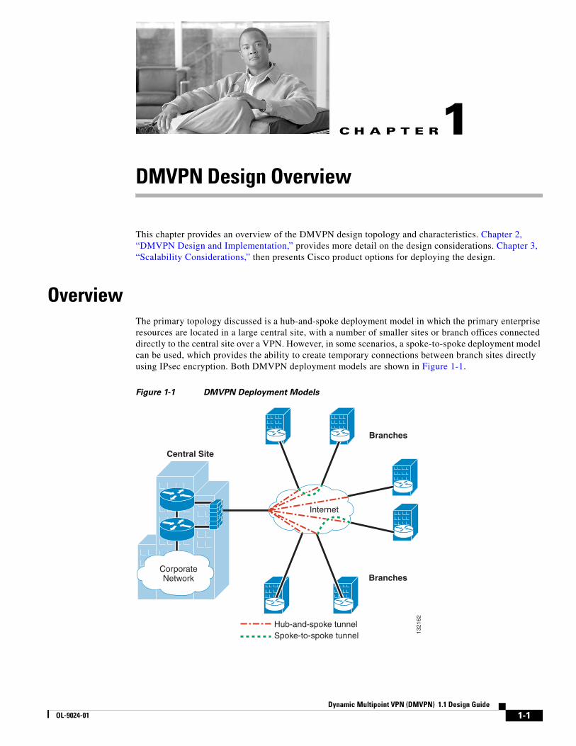
OverviewThe primary topology discussed is a hub-and-spoke deployment model in which the primary enterprise resources are located in a large central site, with a number of smaller sites or branch offices connected directly to the central site over a VPN. However, in some scenarios, a spoke-to-spoke deployment model can be used, which provides the ability to create temporary connections between branch sites directly using IPsec encryption. Both DMVPN deployment models are shown in Figure 1-1.
Figure 1-1 DMVPN Deployment Models
CorporateNetwork
Central Site
1321
62
Internet
Hub-and-spoke tunnelSpoke-to-spoke tunnel
Branches
Branches
1-1ynamic Multipoint VPN (DMVPN) 1.1 Design Guide

Chapter 1 DMVPN Design Overview Overview
Starting AssumptionsThe design approach presented in this design guide makes the following starting assumptions:
• The design supports a typical converged traffic profile for customers (see Chapter 4, “Scalability Test Results (Unicast Only).”)
• The customer has a need for diverse traffic requirements such as IP multicast and support for routing. The use of mGRE and a routing protocol are also discussed in more detail in Chapter 2, “DMVPN Design and Implementation.”
• Cisco products should be maintained at reasonable CPU utilization levels. This is discussed in more detail in Chapter 3, “Scalability Considerations,” including recommendations for both headend and branch routers, and software revisions.
• Although costs were certainly considered, the design recommendations assume that the customer deploys current VPN technologies, including hardware-accelerated encryption.
• Voice over IP (VoIP) and video are assumed to be requirements in the network. Detailed design considerations for handling VoIP and other latency sensitive traffic are not explicitly addressed in this design guide, but may be found in Voice and Video Enabled IPsec VPN (V3PN) Design Guide at the following URL: http://www.cisco.com/go/srnd.
• This design is targeted for deployment by enterprise-owned VPNs; however, the concepts and conclusions are valid regardless of the ownership of the edge tunneling equipment, and are therefore valuable for service provider-managed VPNs as well.
Design ComponentsVPNs provide an alternate to traditional WAN technologies such as leased lines, Frame Relay, and ATM. VPN technology allows private WANs to exist over a public transport such as the Internet. LAN-to-LAN VPNs are primarily deployed to connect branch office locations to the central site (or sites) of an enterprise.
The requirements of enterprise customers for traditional private WAN services such as multiprotocol support, high availability, scalability, and security are also requirements for VPNs. VPNs can often meet these requirements more cost-effectively and with greater flexibility than private WAN services.
The following are key components of this DMVPN design:
• Cisco high-end VPN routers serving as VPN headend termination devices at a central campus (headend devices)
• Cisco VPN access routers serving as VPN branch termination devices at branch office locations (branch devices)
• DMVPN hub-and-spoke to perform headend-to-branch interconnections
• DMVPN spoke-to-spoke to perform branch-to-branch interconnections (optional)
• Internet services procured from a third-party ISP (or ISPs) serving as the WAN interconnection medium
Cisco VPN routers are a good choice for VPN deployments because they can accommodate any network requirement traditionally provided by a Frame Relay or private line network. These requirements include support for multicast, latency-sensitive traffic, and routing protocols. See Chapter 3, “Scalability Considerations,” for a discussion on selection of headend and branch products.
1-2Dynamic Multipoint VPN (DMVPN) 1.1 Design Guide
OL-9024-01

Chapter 1 DMVPN Design Overview Overview
Design TopologiesIn a DMVPN design, the following two topologies can be implemented:
• Dual hub-dual DMVPN cloud
• Dual hub-single DMVPN cloud
In both topologies, two hubs or headends are recommended for redundancy. A DMVPN cloud is a collection of routers that is configured either with a multipoint GRE (mGRE) interface or point-to-point (p2p) GRE interface (or combination of the two) that share the same address subnet. High availability is provided through the use of a second hub router, which may be on the same DMVPN subnet as the primary router. This is commonly referred to as a single DMVPN cloud topology. The second hub router can also service its own DMVPN subnet, which is known as a dual DMVPN cloud topology. A dual hub-single DMVPN topology is generally not recommended because it relies on mechanisms outside of the tunnel to determine the appropriate hub for failover. In contrast, headends using dual DMVPN subnets (dual DMVPN cloud topology) rely on routing protocols running inside of the tunnel to determine path selection.
A DMVPN cloud topology can support either a hub-and-spoke or spoke-to-spoke deployment model. In a hub-and-spoke deployment model, each headend contains an mGRE interface and each branch contains a p2p GRE interface. In a spoke-to-spoke deployment model, both the headend and the branch contain mGRE interfaces.
Figure 1-2 and Figure 1-3 show the two DMVPN cloud topologies. More details on the various deployment models under this topology is discussed in the next section.
Figure 1-2 Dual DMVPN Cloud Topology
148759
Branch subnet Branch subnet Branch subnet
Branch 1 Branch 2
Hub 1(Primary)
Hub 2(Backup)
Branch <n>
Campus
DMVPN 2(subnet 2)
DMVPN 1(subnet 1)
1-3Dynamic Multipoint VPN (DMVPN) 1.1 Design Guide
OL-9024-01

Chapter 1 DMVPN Design Overview Overview
Figure 1-3 Single DMVPN Cloud Topology
The difference between the two topologies is most apparent on the branch router. With a single DMVPN subnet, the branch router has a single mGRE tunnel, and both headends are mapped to this tunnel through an mGRE interface. In a dual DMVPN topology, the branch router has a unique tunnel pointing to a unique headend. Standard routing protocols such as OSPF or EIGRP are used to determine the active hub.
Dual DMVPN Cloud TopologyThe following two deployment models can be implemented in a dual DMVPN cloud topology design:
• Hub-and-spoke
• Spoke-to-spoke
Each of these deployment models is discussed in the following sections.
Dual DMVPN Cloud Topology—Hub-and-Spoke Deployment Model
A dual DMVPN cloud topology hub-and-spoke deployment model consists of two headend routers (Hub 1 and Hub 2), each with one or more mGRE tunnel interface(s) that connect to all branch routers (see Figure 1-4).
148760
Hub 1(Primary)
Hub 2(Backup)
Campus
Branch subnet Branch subnet Branch subnet
Branch 1 Branch 2 Branch <n>
DMVPN 1(subnet 1)
1-4Dynamic Multipoint VPN (DMVPN) 1.1 Design Guide
OL-9024-01

Chapter 1 DMVPN Design Overview Overview
Figure 1-4 Dual DMVPN Cloud Topology—Hub-and-Spoke Deployment Model
Each DMVPN cloud represents a unique IP subnet. One DMVPN cloud is considered the primary, which all branch traffic transits. Each branch is configured with two p2p GRE tunnel interfaces, with one going to each respective headend. In this deployment model, there are no tunnels between branches. Inter-branch communications are provided through the hub routers. This closely matches traditional Frame Relay networks. Routing metrics are used to steer traffic to the primary headend router (Hub 1).
Hub-and-Spoke Deployment Model—Headend System Architectures
The following two headend system architectures can be implemented with hub-and-spoke topologies, depending on the scalability requirements:
• Single Tier Headend Architecture
• Dual Tier Headend Architecture
Single Tier Headend Architecture
In a Single Tier Headend Architecture, the mGRE and crypto functionally co-exist on the same router CPU. Figure 1-5 shows this hub-and-spoke topology.
Hub Site 1
Branch Offices
148761
IP
Hub Site 2
Home Offices
Broadband,Frac-T1, T1
WAN Edge DS3,OC3, OC12
Broadband
Primary DMVPN TunnelSecondary DMVPN Tunnel
DMVPN
DMVPN
1-5Dynamic Multipoint VPN (DMVPN) 1.1 Design Guide
OL-9024-01

Chapter 1 DMVPN Design Overview Overview
Figure 1-5 Single Tier Headend Architecture
In Figure 1-5, the solution is a dual DMVPN cloud topology with the hub-and-spoke deployment model. Both headends are mGRE and crypto tunnel aggregation routers servicing multiple mGRE tunnels for a prescribed number of branch office locations. In addition to terminating the VPN tunnels at the central site, headends can advertise branch routes using IP routing protocols such as EIGRP or OSPF, regardless of which DMVPN cloud path selection is chosen.
Dual Tier Headend Architecture
In a Dual Tier Headend Architecture, the mGRE and crypto functionally do not co-exist on the same router CPU. Figure 1-6 shows this hub-and-spoke topology.
Hub Site 1
Branch Offices
148762
IP
Hub Site 2
Home Offices
Broadband,Frac-T1, T1
WAN Edge DS3,OC3, OC12
Broadband
Primary DMVPN TunnelSecondary DMVPN TunnelIPsec Tunnel
DMVPN
DMVPN
1-6Dynamic Multipoint VPN (DMVPN) 1.1 Design Guide
OL-9024-01

Chapter 1 DMVPN Design Overview Overview
Figure 1-6 Dual Tier Headend Architecture
In Figure 1-6, the solution is a dual DMVPN cloud topology with the hub-and-spoke deployment model. There are separate mGRE headends and crypto headends that together service multiple mGRE tunnels for a prescribed number of branch office locations. The crypto headends terminate the VPN tunnels at the central site from each branch location and then forward the traffic to the mGRE headends that advertise branch routes using IP routing protocols such as EIGRP or OSPF.
Dual DMVPN Cloud Topology—Hub-and-Spoke Deployment Model Branch Router Considerations
Branches in a dual DMVPN cloud topology with the hub-and-spoke deployment model provide p2p GRE over IPsec tunnel(s) from the branch office locations to the central site. In addition to terminating the VPN tunnels, the branch router often provides WAN access, and in some implementations may serve as a firewall.
The public IP address of the branch router is either a statically-defined or a dynamically-assigned IP address. Both the p2p GRE and crypto tunnels are sourced from the public IP address. This address is registered with the headend, which provides a mapping to the branch private address.
Dual DMVPN Cloud Topology—Spoke-to-Spoke Deployment Model
A dual DMVPN cloud topology with the spoke-to-spoke deployment model consists of two headend routers (Hub 1 and Hub 2), each with one or more mGRE tunnel interface(s) that connect to all branch routers (see Figure 1-7). Each DMVPN cloud represents a unique IP subnet. One DMVPN cloud is considered the primary, which all branch traffic transits. On each branch router, there is an mGRE interface into each DMVPN cloud for redundancy. All branch-to-branch communications transit through the primary headend until the dynamic spoke-to-spoke tunnel is created. The dynamic spoke-to-spoke tunnels must be within a single DMVPN cloud or subnet. Spoke-to-spoke tunnels are not possible between two DMVPN clouds.
Hub Site 1
Branch Offices
148763
IP
Hub Site 2
Home Offices
Broadband,Frac-T1, T1
WAN Edge DS3,OC3, OC12
Broadband
Primary DMVPN TunnelSecondary DMVPN TunnelIPsec Tunnel
DMVPN
DMVPN
1-7Dynamic Multipoint VPN (DMVPN) 1.1 Design Guide
OL-9024-01

Chapter 1 DMVPN Design Overview Overview
Figure 1-7 Dual DMVPN Cloud Topology—Spoke-to-Spoke Deployment Model
Spoke-to-Spoke Deployment Model—Headend System Architecture
A dual DMVPN cloud topology with the spoke-to-spoke deployment model supports only the Single Tier Headend Architecture. A Dual Tier Headend Architecture is not a valid option for this topology because spoke-to-spoke connections require the use of tunnel profiles, which are not possible when the crypto tunnel and the GRE tunnel use different endpoints.
Single Tier Headend Architecture
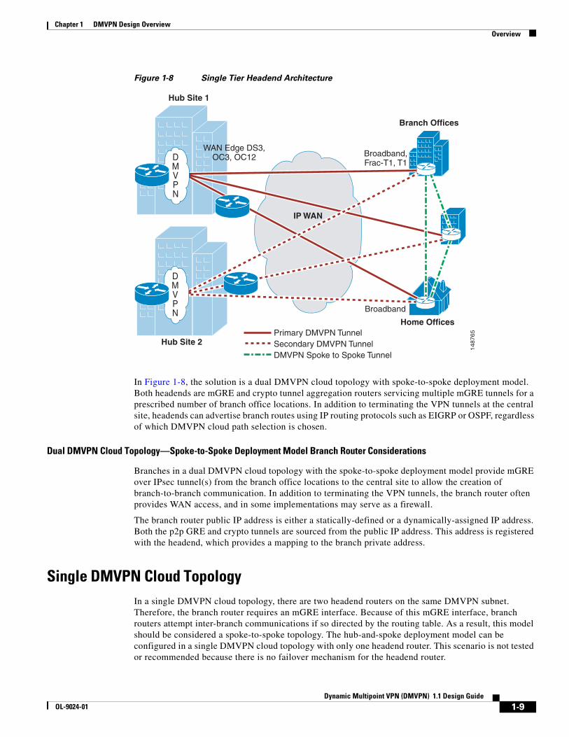
In a Single Tier Headend Architecture, the mGRE and crypto functionally co-exist on the same router CPU. Figure 1-8 shows this spoke-to-spoke topology.
Hub Site 1
Branch Offices
148764
IP WAN
Hub Site 2
Broadband,Frac-T1, T1
WAN Edge DS3,OC3, OC12
Broadband
DMVPN
DMVPN
Home OfficesPrimary DMVPN TunnelSecondary DMVPN TunnelDMVPN Spoke to Spoke Tunnel
1-8Dynamic Multipoint VPN (DMVPN) 1.1 Design Guide
OL-9024-01
Chapter 1 DMVPN Design Overview Overview
Figure 1-8 Single Tier Headend Architecture
In Figure 1-8, the solution is a dual DMVPN cloud topology with spoke-to-spoke deployment model. Both headends are mGRE and crypto tunnel aggregation routers servicing multiple mGRE tunnels for a prescribed number of branch office locations. In addition to terminating the VPN tunnels at the central site, headends can advertise branch routes using IP routing protocols such as EIGRP or OSPF, regardless of which DMVPN cloud path selection is chosen.
Dual DMVPN Cloud Topology—Spoke-to-Spoke Deployment Model Branch Router Considerations
Branches in a dual DMVPN cloud topology with the spoke-to-spoke deployment model provide mGRE over IPsec tunnel(s) from the branch office locations to the central site to allow the creation of branch-to-branch communication. In addition to terminating the VPN tunnels, the branch router often provides WAN access, and in some implementations may serve as a firewall.
The branch router public IP address is either a statically-defined or a dynamically-assigned IP address. Both the p2p GRE and crypto tunnels are sourced from the public IP address. This address is registered with the headend, which provides a mapping to the branch private address.
Single DMVPN Cloud TopologyIn a single DMVPN cloud topology, there are two headend routers on the same DMVPN subnet. Therefore, the branch router requires an mGRE interface. Because of this mGRE interface, branch routers attempt inter-branch communications if so directed by the routing table. As a result, this model should be considered a spoke-to-spoke topology. The hub-and-spoke deployment model can be configured in a single DMVPN cloud topology with only one headend router. This scenario is not tested or recommended because there is no failover mechanism for the headend router.
Hub Site 1
Branch Offices
148765
Hub Site 2
Broadband,Frac-T1, T1
WAN Edge DS3,OC3, OC12
Broadband
Primary DMVPN TunnelSecondary DMVPN TunnelDMVPN Spoke to Spoke Tunnel
DMVPN
DMVPN
Home Offices
IP WAN
1-9Dynamic Multipoint VPN (DMVPN) 1.1 Design Guide
OL-9024-01

Chapter 1 DMVPN Design Overview Best Practices and Known Limitations
A single DMVPN cloud topology with the spoke-to-spoke deployment model also contains two headend routers. The headend routers are configured similarly to the headend router configurations in the dual DMVPN cloud topology, but only one IP subnet is used. If the headends are co-located, traffic can be load balanced between the two headend routers. In this topology, all branch and headend mGRE interfaces are on a single subnet, which contrasts to the dual DMVPN cloud topology where there are multiple subnets each represented by a DMVPN cloud. In this scenario, there is limited control over the routing protocol, and possible asymmetric routing issues may occur. Figure 1-9 shows this deployment model.
Figure 1-9 Single DMVPN Cloud Topology—Spoke-to-Spoke Deployment Model
Although this is a valid topology option, Cisco does not recommend this topology and it is not discussed in detail in this document. For spoke-to-spoke deployment model requirements, Cisco recommends a dual DMVPN cloud topology.
Best Practices and Known LimitationsThe following sections contain a summary of the best practices and limitations for the dual DMPVN cloud topology design. More detailed information is provided in Chapter 2, “DMVPN Design and Implementation.”
Best Practices Summary for Hub-and-Spoke Deployment ModelThis section describes the best practices for a dual DMVPN cloud topology with the hub-and-spoke deployment, supporting IP multicast (IPmc) traffic including routing protocols.
Hub Site 1
Branch Offices
148766
IP WAN
Hub Site 2
Broadband,Frac-T1, T1
WAN Edge DS3,OC3, OC12
Broadband
DMVPN TunnelDMVPN Spoke to Spoke Tunnel
DMVPN
DMVPN
Home Offices
1-10Dynamic Multipoint VPN (DMVPN) 1.1 Design Guide
OL-9024-01

Chapter 1 DMVPN Design Overview Best Practices and Known Limitations
The following are general best practices:
• Use IPsec in tunnel mode
• Configure Triple DES (3DES) or AES for encryption of transported data (exports of encryption algorithms to certain countries may be prohibited by law).
• Implement Dead Peer Detection (DPD) to detect loss of communication between peers.
• Deploy hardware-acceleration of IPsec to minimize router CPU overhead, to support traffic with low latency and jitter requirements, and for the highest performance for cost.
• Keep IPsec packet fragmentation to a minimum on the customer network by setting MTU size or using Path MTU Discovery (PMTUD).
• Use Digital Certificates/Public Key Infrastructure (PKI) for scalable tunnel authentication.
• Configure a routing protocol (for example, EIGRP or OSPF) with route summarization for dynamic routing.
• Set up QoS service policies as appropriate on headend and branch router interfaces to help alleviate interface congestion issues and to attempt to keep higher priority traffic from drops.
The following are general headend best practices:
• Design the deployment to keep the headends below the critical scalability parameters for DMVPN designs:
– Maximum number of spokes per mGRE interface
– Maximum number of total spokes per headend
See Chapter 3, “Scalability Considerations,” for more information.
• Select Cisco VPN router products at the headend based on considerations for the following:
– Number of tunnels to be aggregated
– Maximum throughput in both packets per second (pps) and bits per second (bps) to be aggregated
– Performance margin for resiliency and failover scenarios
– Maintaining CPU utilization below design target
See Chapter 3, “Scalability Considerations,” for more information.
• Distribute branch office tunnels across a number of headend routers to balance loading and aggregation capacity of the hub(s).
The following is a Single Tier Headend Architecture best practice:
• Configure mGRE and IPsec tunnel protection on headend routers to simplify configurations and provisioning of new branches.
The following is a Dual Tier Headend Architecture best practice:
• Use dynamic crypto maps on the crypto headend to reduce the amount of IPsec configuration required.
The following are branch office best practices:
• Configure the branch with p2p GRE and IPsec tunnel protection.
• Configure two tunnels to alternate headends, using routing metrics to designate a primary and secondary path.
• Select Cisco VPN router products at the branch offices based on considerations for:
– Maximum throughput in both pps and bps
1-11Dynamic Multipoint VPN (DMVPN) 1.1 Design Guide
OL-9024-01

Chapter 1 DMVPN Design Overview Best Practices and Known Limitations
– Allowances for other integrated services that may be running on the router, such as for example firewall, IPS, and NAT/PAT
See Chapter 3, “Scalability Considerations,” for more information.
• Configure qos pre-classify in VPN designs where both QoS and IPsec occur on the same system. The network manager should verify correct operation.
Known Limitations Summary for Hub-and-Spoke Deployment ModelThis section describes at a high level the known limitations for a dual DMVPN cloud topology with the hub-and-spoke deployment.
The following are general limitations:
• mGRE acceleration is not currently supported on the Cisco Catalyst 6500/7600 router with VPNSM or VPN SPA, because neither VPN service module supports the mGRE tunnel key. These platforms can be used in designs that do not require an mGRE tunnel key. For more details, see Chapter 2, “DMVPN Design and Implementation.”
• There are significant scalability limitations for supporting IP multicast over DMVPN designs. See the Multicast over IPsec VPN Design Guide for more information at the following URL: http://www.cisco.com/go/srnd.
• qos pre-classify must be applied on the mGRE tunnel interface, because it is not currently supported by IPsec tunnel protection.
The following is a general headend limitation:
• Limited QoS can be implemented in the hub-to-branch direction on the outside interface, because it is not possible to configure a service policy at the tunnel level. This is interface level QoS, not per branch and is executed post encryption.
The following are Dual Tier Headend Architecture limitations:
• Tunnel protection is not supported.
• qos pre-classify is not supported in an architecture that implements two different headends for mGRE tunnels and VPN tunnels.
The following is a branch office limitation:
• Branches must always initiate the DMVPN tunnel to the headend router; the headend cannot initiate the tunnel to the branch router.
Best Practices Summary for Spoke-to-Spoke Deployment ModelThis section summarizes the best practices for a dual DMVPN cloud topology with the spoke-to-spoke deployment. These best practices should be considered in addition to the best practices for hub-and-spoke deployments.
The following are general best practices:
• Set desired tunnel persistence timers via NHRP hold time, with consideration for IPsec SA lifetimes. For more details, see Chapter 2, “DMVPN Design and Implementation.”
• Use a /24 prefix to provide a practical balance of the number of spokes in a given DMVPN cloud (subnet). Multiple mGRE interfaces may be deployed on a DMVPN hub to increase scalability.
• Use EIGRP or RIPv2 routing protocols for spoke-to-spoke deployment models.
1-12Dynamic Multipoint VPN (DMVPN) 1.1 Design Guide
OL-9024-01

Chapter 1 DMVPN Design Overview Best Practices and Known Limitations
The following is a branch office best practice:
• Configure IKE Call Admission Control (IKE CAC) to limit the maximum number of spoke-to-spoke tunnels that can be accepted by a branch router, after which the tunnels go spoke-to-hub-to-spoke.
For more information, see IKE Call Admission Control, page 2-10.
• mGRE must be configured on the branch router.
Known Limitations Summary for Spoke-to-Spoke Deployment ModelThis section describes at a high level the known limitations for a dual DMVPN cloud topology with the spoke-to-spoke deployment. These known limitations should be considered in addition to the known limitations for hub-and-spoke deployments.
The following are general limitations:
• ODR cannot be used in spoke-to-spoke topologies.
• OSPF is not recommended as a routing protocol in a spoke-to-spoke deployment model because of scaling limitations. For more information, see Chapter 3, “Scalability Considerations.”
The following is a headend limitation:
• mGRE and IPsec source and destination IP addresses must be identical for spoke-to-spoke mode to function, which is not possible with a Dual Tier Headend Architecture.
The following are branch office limitations:
• Very limited QoS can be provided between spokes. Therefore, latency-sensitive applications such as VoIP and video are considered “best effort” in spoke-to-spoke DMVPN deployments.
• Dynamic routing is not exchanged between spokes over a spoke-to-spoke tunnel. As a result, communication can be lost without knowing the tunnel is down.
• Spokes behind a pNAT device cannot establish spoke-to-spoke tunnels.
• No IP multicast traffic can be exchanged between spokes.
• In a spoke-to-spoke topology, any traffic can bring an IPsec tunnel to another branch in that DMVPN cloud. Because this is done at the L3 (routing) level, any IP unicast traffic can then transit over that spoke-to-spoke tunnel. This may be a security issue for some deployments because viruses, worms, or attack software may spread branch-to-branch without the headend as a check point. Other protection mechanisms such as IPS should be implemented at every branch that is spoke-to-spoke capable.
• IKE CAC has limitations as well as the maximum number of ISAKMP SA per branch platform. For more information, see IKE Call Admission Control, page 2-10.
Additional detailed information on these recommendations is discussed in the chapters that follow.
1-13Dynamic Multipoint VPN (DMVPN) 1.1 Design Guide
OL-9024-01
DOL-9024-01
C H A P T E R2
DMVPN Design and ImplementationIn designing a VPN deployment for a customer, it is essential to integrate broader design considerations, such as high availability and resiliency, IP multicast, and QoS. This chapter starts with an overview of some general design considerations, followed by sections on implementation, high availability, QoS, and multicast.
Design ConsiderationsHeadend sites are typically connected with DS3, OC3, or even OC12 bandwidth, while branch offices may be connected by fractional T1, T1, E1, T3, or increasingly, broadband DSL or cable access.
To provide redundancy, the branch router should have two or more tunnels to the campus headends. These headend routers can be geographically separated or co-located. For maximum protection, both headend and site redundancy should be implemented. This design guide focuses on the dual DMVPN cloud topology, with both a hub-and-spoke deployment model and a spoke-to-spoke deployment model.
Each deployment model in a dual DMVPN cloud topology has three control planes: the IPsec control plane, the Generic Routing Encapsulation (GRE) control plane, and the routing control plane. Which headend system architecture is chosen determines how each of the control planes is implemented. The following sections provide more detail.
TopologyThe following two topologies can be implemented in a DMVPN design:
• Dual hub-dual DMVPN cloud
• Dual hub-single DMVPN cloud
In this design guide, only the dual hub-dual DMVPN cloud topology is discussed because Cisco recommends this topology for DMVPN designs. A dual topology allows the network manager greater control over path selection than in a single topology. In addition, the primary failover method is a dynamic routing protocol. A single cloud topology relies on NHRP handle failure events. A dual DMVPN cloud topology can support either a hub-and-spoke deployment model or a spoke-to-spoke deployment model.
The hub-and-spoke deployment model is the most common deployment model. This model is the most scalable, and predominately mimics traditional Layer 2 leased line, Frame Relay, or ATM hub-and-spoke networks. The headend is configured with a multipoint GRE (mGRE) interface, and the branch with a point-to-point (p2p) GRE interface.
2-1ynamic Multipoint VPN (DMVPN) 1.1 Design Guide

Chapter 2 DMVPN Design and Implementation Design Considerations
The spoke-to-spoke deployment model allows branches to dynamically create tunnels between other branches within the same DMVPN cloud for intercommunication. This deployment model is a fully-meshed topology and requires mGRE interfaces to be configured on both the headend and all branches.
Dual DMVPN Hub-and-SpokeThe hub-and-spoke deployment model in a dual-cloud topology consists of two headend routers, each with one or more mGRE tunnel interface(s) that connect to all branch routers. Each DMVPN cloud represents a unique IP subnet. One DMVPN cloud is considered the primary over which all branch traffic transits. Each branch is configured with p2p GRE tunnel interfaces, with one going to each respective headend. In this deployment model, no tunnels connect one branch to another branch. Traffic between branches passes through the hub router. Routing metrics are used to determine which headend is the preferred path.
The following two headend system architectures are described in this design guide:
• Single Tier Headend Architecture—Incorporates both the mGRE and crypto functions into a single router processor
• Dual Tier Headend Architecture—Splits the mGRE and crypto functions into two different routers or chasses.
Dual DMVPN Cloud Topology—Hub-and-Spoke Deployment Model (Single Tier Headend Architecture)
Figure 2-1 shows the Single Tier Headend Architecture in a DMVPN deployment.
2-2Dynamic Multipoint VPN (DMVPN) 1.1 Design Guide
OL-9024-01

Chapter 2 DMVPN Design and Implementation Design Considerations
Figure 2-1 Dual DMVPN Cloud Topology—Hub-and-Spoke Deployment Model (Single Tier
Headend Architecture)
The Single Tier Headend Architecture incorporates all three of the above control planes into a single router. This architecture has an impact on scalability, where the central CPU becomes the gating factor.
Dual DMVPN Cloud Topology—Hub-and-Spoke Deployment Model (Dual Tier Headend Architecture)
Figure 2-2 shows the Dual Tier Headend Architecture in a DMVPN deployment.
Hub Site 1
Branch Offices
148767
IP
Hub Site 2
Home Offices
Broadband,Frac-T1, T1
WAN Edge DS3,OC3, OC12
Broadband
Primary DMVPN TunnelSecondary DMVPN Tunnel
DMVPN
DMVPN
Routing ControlPlane
DynamicRouting NHRP
IPsec ControlPlane
Tunnel Protection orDynamic Crypto Map DPD Tunnel Protection or
Static Crypto Map DPD
Headend Branch
DynamicRouting NHRP
GRE ControlPlane
MultipointGRE
Point-to-PointGRE
2-3Dynamic Multipoint VPN (DMVPN) 1.1 Design Guide
OL-9024-01

Chapter 2 DMVPN Design and Implementation Design Considerations
Figure 2-2 Dual DMVPN Cloud Topology—Hub-and-Spoke Deployment Model (Dual Tier
Headend Architecture)
The Dual Tier Headend Architecture incorporates the above three control planes into two routers. Both the routing and GRE control planes are housed on one router, while the IPsec control plane is housed on another. Separating the functionality provides the best scalable solution given various platform limitations; specifically CPU dependencies and resiliency.
Dual DMVPN Cloud Topology—Spoke-to-Spoke Deployment ModelSpoke-to-spoke deployment in a dual DMVPN topology consists of two headend routers, each with one or more mGRE tunnel interface(s) that connect to all branch routers. Each DMVPN cloud represents a unique IP subnet. One DMVPN cloud is considered the primary, over which all branch traffic transits. On each branch router, there is an mGRE interface into each DMVPN cloud for redundancy. All branch-to-branch communications transit through the primary headend until the dynamic spoke-to-spoke tunnel is created. The dynamic spoke-to-spoke tunnels must be within a single DMVPN cloud or subnet. It is not possible to dynamically create a spoke-to-spoke tunnel between two DMVPN clouds.
Hub Site 1
Branch Offices
148768
IP
Hub Site 2
Home Offices
Broadband,Frac-T1, T1
WAN Edge DS3,OC3, OC12
Broadband
Primary DMVPN TunnelSecondary DMVPN Tunnel
DMVPN
DMVPN
Routing ControlPlane
DynamicRouting NHRP
IPsec ControlPlane
DynamicCrypto Map DPD Static
Crypto Map DPD
Headend Branch
DynamicRouting NHRP
GRE ControlPlane
MultipointGRE
Point-to-PointGRE
2-4Dynamic Multipoint VPN (DMVPN) 1.1 Design Guide
OL-9024-01

Chapter 2 DMVPN Design and Implementation Design Considerations
Dual DMVPN Cloud Topology—Spoke-to-Spoke Deployment Model (Single Tier Headend Architecture)
Figure 2-3 shows the Single Tier Headend Architecture in a DMVPN deployment.
Figure 2-3 Dual DMVPN Cloud Topology—Spoke-to-Spoke Deployment Model (Single Tier
Headend Architecture)
The dual DMVPN cloud topology spoke-to-spoke deployment model with the Single Tier Headend Architecture is very similar to the hub-and-spoke deployment model, with the exception that all GRE interfaces in the headend and the branch are mGRE interfaces. Branch routers can initiate and accept dynamic tunnels from other branch offices.
IP AddressingCisco highly recommends using proper address summarization, which accomplishes the following:
• Conserves router resources, making routing table sizes smaller
• Saves memory in routers and eases troubleshooting tasks
Hub Site 1
Branch Offices
148769
IP
Hub Site 2
Home Offices
Broadband,Frac-T1, T1
WAN Edge DS3,OC3, OC12
Broadband
DMVPN
DMVPN
Routing ControlPlane
DynamicRouting NHRP
IPsec ControlPlane DPD DPD
Headend Branch
DynamicRouting NHRP
GRE ControlPlane
MultipointGRE
Point-to-PointGRE
Primary DMVPN TunnelSecondary DMVPN TunnelDMVPN Spoke to Spoke Tunnel
TunnelProtection
TunnelProtection
2-5Dynamic Multipoint VPN (DMVPN) 1.1 Design Guide
OL-9024-01

Chapter 2 DMVPN Design and Implementation Design Considerations
• Simplifies the configuration of routers in IPsec networks
VPNs are used for secure enterprise communications across a shared public infrastructure such as the Internet. Two distinct IP address domains must be considered: the enterprise addressing space, sometimes referred to as the private or inside addresses; and the infrastructure addressing space, also referred to as the service provider, public, or outside addresses. (See Figure 2-4.)
Figure 2-4 Private and Public Address Spaces
In most DMVPN designs, the outside interface of the router is addressed in the infrastructure (or public) address space, assigned by the service provider. The tunnel interface belongs to the enterprise private network address space. A branch router public IP address is either a statically defined or a dynamically assigned IP address. For a hub-and-spoke deployment model, both the p2p GRE and crypto tunnels are sourced from the public IP address. For a spoke-to-spoke deployment model, the mGRE and crypto tunnels are also sourced from the public IP address. This address is registered with the headend router, which provides a mapping to the branch private address.
Generic Routing Encapsulation—p2p GRE and mGRE InterfacesAlthough IPsec provides a secure method for tunneling data across an IP network, it has several limitations. First, IPsec does not support broadcast or IP multicast (IPmc), preventing the use of protocols that rely on these features, such as routing protocols.
Generic Routing Encapsulation (GRE) is a protocol that can be used to “carry” other passenger protocols such as broadcast or multicast IP, as is shown in Figure 2-5.
Tunnel Interface
PrivateAddressSpace
PublicAddressSpace
PrivateAddressSpace
Outside Interface
Outside Interface
Tunnel Interface
1261
30
2-6Dynamic Multipoint VPN (DMVPN) 1.1 Design Guide
OL-9024-01

Chapter 2 DMVPN Design and Implementation Design Considerations
Figure 2-5 GRE as a Carrier Protocol of IP
Using GRE tunnels in conjunction with IPsec provides the ability to run a dynamic routing protocol or IPmc across the network between the headend(s) and branch offices.
With the p2p GRE over IPsec solution, all traffic between sites is encapsulated in a p2p GRE packet before the encryption process, simplifying the access list used in the crypto map statements. The crypto map statements need only one line permitting GRE (IP Protocol 47). However, in this design, the headend router requires a unique tunnel interface for each branch router, so a large-scale design can have a very large Cisco IOS configuration file on the headend router. For more information on p2p GRE over IPsec designs, see the Point-to-Point GRE over IPsec Design Guide at the following URL: http://www.cisco.com/go/srnd.
In DMVPN designs, an mGRE interface is introduced, which serves as a “one-to-many” interface for the creation of multiple hub-and-spoke tunnels that work similarly to a point-to-multipoint Frame Relay interface. Unlike p2p GRE tunnels, the tunnel destination for an mGRE tunnel does not have to be configured. In all DMVPN designs, the headend is configured with an mGRE interface to allow the dynamic creation of tunnels for each branch connected. An mGRE interface does not require a unique tunnel interface, a unique crypto map, or a unique crypto ACL for each branch in the network. mGRE interfaces reduce the configuration file on each headend router, which is an advantage for large-scale designs when compared to static p2p GRE topologies.
The deployment model chosen determines which type of GRE interface is configured on a branch router. A hub-and-spoke deployment model requires each branch to be configured with a p2p GRE interface. A spoke-to-spoke deployment model requires each branch to be configured with an mGRE interface.
Both p2p GRE and mGRE add to the size of the original data packet, including a four-byte GRE header, a four-byte mGRE tunnel key, and 20 bytes for an additional IP header.
The protocol header for an mGRE packet is four bytes larger than a p2p GRE packet. The additional four bytes constitute a tunnel key value, which is used to differentiate between different mGRE interfaces in the same router. Without a tunnel key, a router can support only one mGRE interface corresponding to one IP network. Tunnel keys allow a branch router to have a different mGRE interface corresponding to each DMVPN cloud in the network topology. A headend router can be configured as well with two mGRE interfaces pointing to each DMVPN cloud for high availability and redundancy.
Cisco IOS Software Releases 12.3(13)T, 12.3(11)T3, or later allow multiple mGRE interfaces on a single router to be configured without tunnel keys. Each mGRE interface must reference a unique IP address as its tunnel source.
Next Hop Resolution ProtocolNext Hop Resolution Protocol (NHRP), defined in RFC 2332, is a Layer 2 address resolution protocol and cache, like Address Resolution Protocol (ARP) and Frame Relay Inverse-ARP. NHRP is used by a branch router connected to a non-broadcast, multi-access (NBMA) sub-network to determine the IP address of the “NBMA next hop”; in this case, the headend router or the destination IP address of another branch router.
CarrierProtocol
GRE
TransportProtocol
IP/UDP
PassengerProtocol
Network Packet
1261
29
2-7Dynamic Multipoint VPN (DMVPN) 1.1 Design Guide
OL-9024-01

Chapter 2 DMVPN Design and Implementation Design Considerations
When a branch router is first established onto a DMVPN network, it registers its IP address with the headend router whose IP address is already pre-configured on the branch router. This registration enables the mGRE interface on the headend router to build a dynamic tunnel back to the registering branch router without having to know the branch tunnel destination through a CLI configuration. NHRP maps a tunnel IP address to an NBMA IP address. NHRP tells the mGRE interface where to tunnel a packet to reach a certain address. When the packet is encapsulated in the mGRE packet, the IP destination address is the NBMA address. Figure 2-6 shows an example of NHRP and mGRE addressing.
Figure 2-6 NHRP and mGRE addressing
If the destination address is connected to the NBMA sub-network, the headend router is the destination itself. Otherwise, the headend route is the egress router closest to the branch requesting a destination IP address.
Headend and branch routers should be configured with an NHRP holdtime, which sets the length of time that routers instruct other routers to keep their NHRP information. This information is kept in the NHRP cache until the NHRP holdtime expires and the information must be relearned. The default NHRP holdtime is two hours; however, the recommended value is ten minutes. The NHRP cache can be populated with either static or dynamic entries. On the headend router, all entries are added dynamically via registration or resolution requests. The branch router is configured with a static NHRP map pointing to the headend router. To participate in one NHRP registration process, all routers must belong to the same NHRP network by a network ID. The NHRP network ID defines an NHRP domain.
Branch routers must be configured with the NBMA address of the headend router as their next hop server (NHS) to register with the headend router. The branch routers send a registration to the headend router that contains the tunnel IP address and the NBMA address. The headend router creates an entry in its NHRP cache and returns a registration reply. The branch router now views the headend router as a valid NHS and uses it as a source to locate any other branches and networks in the NHRP domain.
Tunnel Protection ModeIn typical IPsec configurations, dynamic or static crypto maps are configured on the headend and branch routers. These crypto maps specify which IPsec transform set is used and specify a crypto ACL that defines interesting traffic for the crypto map. In Cisco IOS Release 12.2(13)T or later, IPsec profiles are introduced, which share most of the same commands with the crypto map configuration; however, only
9251
4
Tunnel address10.0.0.1/24
IPs = 172.16.0.1d = 172.16.0.2
IPs = 192.168.0.1d = 192.168.1.1
GRE Payload
NBMA address172.16.0.1/24
NHRP Table10.0.0.2 -> 172.16.0.2
Routing Table192.168.1.0/24 -> Tunnel0 via 10.0.0.2
192.168.0.0/24 192.168.1.0/24
Tunnel address10.0.0.2/24
NBMA address172.16.0.2/24
2-8Dynamic Multipoint VPN (DMVPN) 1.1 Design Guide
OL-9024-01
Chapter 2 DMVPN Design and Implementation Design Considerations
a subset of the commands is needed in an IPsec profile. Only commands that pertain to an IPsec policy can be used under an IPsec profile. There is no need to specify the IPsec peer address or the ACL to match the packets that are to be encrypted.
To associate either a p2p GRE or mGRE tunnel with an IPsec profile on the same router, tunnel protection must be configured. Tunnel protection specifies that IPsec encryption is performed after the GRE headers are added to the tunnel packet. With p2p GRE tunnels, the tunnel destination IP address is used as the IPsec peer address. With mGRE tunnels, multiple IPsec peers are possible; the corresponding NHRP-mapped NBMA destination addresses are used as the IPsec peer address. Tunnel protection must be configured on both the headend router and the branch router for a spoke-to-spoke deployment.
If more than one mGRE tunnel is configured on a router, the shared keyword must be configured to reference the same tunnel source address on each tunnel interface. Each mGRE tunnel interface still requires a unique tunnel key, NHRP network-ID, and IP subnet address. This is common on a branch router when a dual DMVPN cloud topology is deployed.
Note that the GRE tunnel keepalives are not supported in combination with tunnel protection. In addition, tunnel protection cannot be used in a Dual Tier Headend Architecture.
Using a Routing Protocol across the VPNThis design recommends the use of a dynamic routing protocol to propagate routes from the headend to the branch offices. Using a routing protocol has several advantages over the current mechanisms in IPsec Direct Encapsulation alone.
In a VPN, routing protocols provide the same level of benefits as compared to a traditional network, which include the following:
• Network topology information
• Topology change notification (such as when a link fails)
• Remote peer status
Several routing protocols can be used in a DMVPN design, including EIGRP, OSPF, RIPv2, and ODR (DMVPN hub-and-spoke only). Designs presented in this design guide use EIGRP as the routing protocol, because EIGRP was used during the scalability testing. EIGRP is recommended as the dynamic routing protocol because of its conservation of router CPU cycles and network bandwidth, as well as its quick convergence times. EIGRP also provides a range of options for address summarization and default route propagation.
Other routing protocols such as OSPF have also been verified, but are not discussed in great detail. ODR cannot be used in the spoke-to-spoke deployment model because ODR does not support split tunneling.
Routing protocols increase the CPU utilization on a network device, so this impact must be considered when sizing those devices.
Route Propagation StrategyWhen a branch connection to the network comes up, the branch router is ready to begin transmitting routing protocol information because it has a static NHRP entry to the headend router. Because the headend router must wait for the NHRP cache to be populated by the branch router, the headend router cannot begin sending routing protocol information until after the branch registers its NBMA address with the next hop server (NHS).
2-9Dynamic Multipoint VPN (DMVPN) 1.1 Design Guide
OL-9024-01
Chapter 2 DMVPN Design and Implementation Design Considerations
Crypto ConsiderationsIPsec supports transport and tunnel encryption modes. Transport mode encrypts only the data portion (payload) of each packet, leaving the source and destination address in the header untouched. The more secure tunnel mode encrypts both the header and payload of the original packet. The difference between these two is that tunnel mode protects the original IP datagram header, and transport mode does not. Tunnel mode adds an additional 20 bytes to the total packet size. Either tunnel or transport mode works in a DMVPN implementation; however, several restrictions with transport mode should be understood. If the crypto tunnel transits either a Network Address Translation (NAT) or Port Address Translation (PAT) device, tunnel mode is required. In addition, this design guide shows configuration examples for implementing DMVPN where the GRE tunnel endpoints are different from the crypto tunnel endpoints (dual Tier). Tunnel mode is required in these cases.
IKE Call Admission ControlBefore Cisco IOS Release 12.3(8)T, there was no means of controlling the number and rate of simultaneous Internet Security Association and Key Management Protocol (ISAKMP) security association (SA) requests received by IKE, which can result in a router being overloaded if more incoming ISAKMP SAs than the processor can handle are initiated. These capabilities are platform-specific. If the processor becomes over-committed, IKE negotiation failures and the constant retransmissions of IKE packets can further degrade router performance.
IKE Call Admission Control (CAC) was introduced in Cisco IOS Release 12.3(8)T to limit the number of IKE authentication of ISAKMP SAs permitted to and from a router. By limiting the amount of dynamic crypto peers that can be created, you can prevent the router from being overwhelmed if it is suddenly inundated with ISKAMP SA requests. The ideal limit depends on the particular platform, the network topology, the application, and traffic patterns. When the specified limit is reached, IKE CAC rejects all new ISAKMP SA requests. If you specify an IKE CAC limit that is less than the current number of active IKE SAs, a warning is displayed, but ISAKMP SAs are not terminated. New ISAKMP SA requests are rejected until the active ISAKMP SA count is below the configured limit.
CAC provides two implementations for limiting IKE SAs that can benefit a DMVPN implementation. First, the normal CAC feature is a global resource monitor that is polled to ensure that all processes including IKE do not overrun router CPU or memory buffers. The user can configure a resource limit, represented by a percentage of system resources from 0 to 100. If the user specifies a resource limit of 90 percent, then IKE CAC drops ISAKMP SA requests when 90 percent of the system resources are being consumed. This feature is valuable on headend routers that can classify and encrypt packets in hardware crypto engines at line rate. It is less useful on branch routers in a hub-and-spoke deployment model, because the branch router typically reaches capacity before being fully loaded with ISAKMP SAs.
The second approach allows the user to configure an IKE authentication limit of ISAKMP SAs (IKE CAC). When this limit is reached, IKE CAC drops all new ISAKMP SA requests. IPsec SA re-key requests are always allowed because the intent is to preserve the integrity of existing sessions. This functionality is primarily targeted at branch routers in a spoke-to-spoke deployment model. By configuring a limit to the amount of dynamic tunnels that can be created to the device, the user can prevent a router from being overwhelmed if it is suddenly inundated with SA requests. The ideal IKE CAC limit to configure depends heavily on the particular platform and crypto engine (CE), the network topology, and feature set being deployed.
2-10Dynamic Multipoint VPN (DMVPN) 1.1 Design Guide
OL-9024-01

Chapter 2 DMVPN Design and Implementation Configuration and Implementation
Configuration and ImplementationThe configuration issues defined in this chapter are specific to VPN implementation for the dual DMVPN design topology. It is presumed that the reader is reasonably familiar with standard Cisco configuration practices at the command-line interface (CLI) level.
All references to private or public IP addresses correlate to IP Addressing, page 2-5.
For step-by-step instructions, see the following URL: http://www.cisco.com/en/US/partner/tech/tk583/tk372/tsd_technology_support_protocol_home.html
ISAKMP Policy ConfigurationThere must be at least one matching ISAKMP policy between two potential crypto peers. The sample configuration below shows a policy using Pre-Shared Keys (PSKs) with 3DES as the encryption algorithm, and SHA as the HMAC. There is a default ISAKMP policy that contains the default values for the encryption algorithm, hash method (HMAC), Diffie-Hellman group, authentication type, and ISAKMP SA lifetime parameters. This is the lowest priority ISAKMP policy.
When using PSK, Cisco recommends that wildcard keys should not be used. However, when implementing a DMVPN design using an IP address obtained dynamically, the use of a wildcard PSK is required. Another approach is the use of Public Key Infrastructure (PKI), also known as Digital Certificates. The example shows two keys configured for two separate crypto peers. The keys should be carefully chosen; “bigsecret” is used only as an example. The use of alphanumeric and special characters as keys is recommended.
The following configuration example shows a static public IP address on the branch router with a static public IP address on the headend router for the crypto peer for either a Single or Dual Tier Headend Architecture:
• Headend router:
interface FastEthernet1/0ip address 192.168.251.1 255.255.255.0!crypto isakmp policy 10 encr 3des authentication pre-sharecrypto isakmp key bigsecret address 192.168.161.2
• Branch router:
interface Serial0/0ip address 192.168.161.2 255.255.255.0!crypto isakmp policy 10 encr 3des authentication pre-sharecrypto isakmp key bigsecret address 192.168.251.1
Note the following:
• In a Single Tier Headend Architecture, the configuration above is applied to the headend router.
• Ι n a Dual Tier Headend Architecture, the configuration above is applied to the crypto headend router.
• In either headend architecture implementing a branch with a dynamic public IP address, a wildcard PSK or PKI must be used on the crypto headend router.
2-11Dynamic Multipoint VPN (DMVPN) 1.1 Design Guide
OL-9024-01
Chapter 2 DMVPN Design and Implementation Configuration and Implementation
For more information regarding configuring ISAKMP policies, see the following URL: http://www.cisco.com/univercd/cc/td/doc/product/software/ios122/122cgcr/fsecur_r/fipsencr/srfike.htm#wp1017989
IPsec Transform and Protocol ConfigurationThe transform set must match between the two IPsec peers. The transform set names are locally significant only. However, the encryption algorithm, hash method, and the particular protocols used (ESP or AH) must have at least one match. Data compression may also be configured, but it is not recommended on peers with high-speed links. There can be multiple transform sets for use between different peers, with the strongest match being negotiated.
The following configuration example shows a static public IP address on the branch router, with a static public IP address on the headend router for the crypto peer for either a Single or Dual Tier Headend Architecture:
• Headend router:
interface FastEthernet1/0ip address 192.168.251.1 255.255.255.0!crypto isakmp policy 10 encr 3des authentication pre-sharecrypto isakmp key bigsecret address 192.168.161.2crypto isakmp keepalive 10!!crypto ipsec transform-set vpn-test esp-3des esp-sha-hmac
• Branch router:
interface Serial0/0ip address 192.168.161.2 255.255.255.0!crypto isakmp policy 10 encr 3des authentication pre-sharecrypto isakmp key bigsecret address 192.168.251.1crypto isakmp keepalive 10!!crypto ipsec transform-set vpn-test esp-3des esp-sha-hmac
Note the following:
• In a Single Tier Headend Architecture, the configuration above is applied to the headend router.
• In a Dual Tier Headend Architecture, the configuration above is applied to the crypto headend router.
• In either headend architecture implementing a branch with a dynamic public IP address, a wildcard PSK or PKI must be used on the crypto headend router.
For more information on transform sets and configuring crypto maps, see the following URL: http://www.cisco.com/univercd/cc/td/doc/product/software/ios122/122cgcr/fsecur_r/fipsencr/srfipsec.htm#xtocid105784
2-12Dynamic Multipoint VPN (DMVPN) 1.1 Design Guide
OL-9024-01

Chapter 2 DMVPN Design and Implementation Configuration and Implementation
Tunnel Protection ConfigurationTunnel protection can be used when the GRE tunnel and the crypto tunnel share the same endpoints. Because of this restriction, tunnel protection is applicable only to the Single Tier Headend Architecture.
In early versions of IPsec configurations, dynamic or static crypto maps specify which IPsec transform set (encryption strength and Diffie-Hellman group) and also specify a crypto access list, which defines interesting traffic for the crypto map. As of Cisco IOS Software Release 12.2(13)T, the concept of an IPsec profile exists. The IPsec profile shares most of the same commands with the crypto map configuration, but only a subset of the commands is needed in an IPsec profile. These commands pertain to an IPsec policy that can be issued under an IPsec profile; there is no need to specify the IPsec peer address or the ACL to match the packets that are to be encrypted.
A sample IPsec profile is shown in the following example:
• Headend router:
crypto ipsec transform-set ESE esp-3des esp-sha-hmac mode transport!crypto ipsec profile VPN-DMVPNset security-association lifetime 60set transform-set ESE!
• Branch router:
crypto ipsec transform-set ESE esp-3des esp-sha-hmacmode transport!crypto ipsec profile VPN-DMVPNset security-association lifetime 60set transform-set ESE!
The IPsec profile is associated with a tunnel interface using the tunnel protection ipsec profile profile-name command, also first introduced in Cisco IOS Software Release 12.2(13)T. The tunnel protection command can be used with mGRE and p2p GRE tunnels. With p2p GRE tunnels, the tunnel destination address is used as the IPsec peer address. With mGRE tunnels, multiple IPsec peers are possible; the corresponding NHRP-mapped NBMA destination addresses are used as the IPsec peer addresses. Crypto access lists that define the interesting traffic no longer need to be configured.
If more than one mGRE tunnel is configured on a router (for example, on a branch router with dual DMVPN clouds), it is possible to reference the same tunnel source address on each tunnel interface. In this case, the shared keyword is used in the tunnel protection command on both interfaces. This does not mean that the two mGRE tunnels are hosting the same DMVPN cloud; each tunnel interface still requires a unique NHRP network-ID and IP subnet.
Dynamic Crypto Map ConfigurationThe dynamic crypto map is required only in a dual tier architecture where tunnel protection cannot be used. The following configuration examples show a dynamic public IP address on the branch router with a static public IP address on the headend router using a Dual Tier Headend Architecture:
• Headend router:
interface FastEthernet1/0ip address 192.168.251.1 255.255.255.0!
2-13Dynamic Multipoint VPN (DMVPN) 1.1 Design Guide
OL-9024-01

Chapter 2 DMVPN Design and Implementation Configuration and Implementation
crypto isakmp key bigsecret address 0.0.0.0 0.0.0.0!crypto dynamic-map dmap 10 set transform-set vpn-test!!crypto map dynamic-map local-address FastEthernet1/0crypto map dynamic-map 10 ipsec-isakmp dynamic dmap
• Branch router:
interface Serial0/0ip address dhcp!crypto isakmp key bigsecret address 192.168.251.1!crypto map static-map local-address Serial0/0crypto map static-map 20 ipsec-isakmp set peer 192.168.251.1 set transform-set vpn-test match address vpn-static2
Note the following:
• On the headend router, a dynamic crypto map is used with a wildcard PSK to allow a crypto peer with the public dynamically-served IP address of the branch router.
• In a Dual Tier Headend Architecture, the configuration above is applied to the crypto headend router.
For a more complete description of the various crypto configuration commands, see the following URL: http://www.cisco.com/univercd/cc/td/doc/product/software/ios122/122cgcr/fsecur_r/fipsencr/srfipsec.htm
Applying Crypto MapsCrypto maps are required only when a Dual Tier Headend Architecture is used. The crypto map is applied on the routers outside the public address. The branch router must also be configured with a static crypto map when a Dual Tier Headend Architecture is used because the encryption tunnel destination differs from the GRE tunnel destination.
The following configuration example shows a public dynamic IP address on the branch router with a static public IP address on the headend router for the crypto peers for a Dual Tier Headend Architecture:
• Headend router:
interface FastEthernet1/0 ip address 192.168.251.1 255.255.255.0 crypto map dynamic-map!
• Branch router:
interface Serial0/0 ip address dhcp crypto map static-map!
In a Dual Tier Headend Architecture, the configuration above is applied to the crypto headend router.
2-14Dynamic Multipoint VPN (DMVPN) 1.1 Design Guide
OL-9024-01

Chapter 2 DMVPN Design and Implementation Configuration and Implementation
mGRE ConfigurationThe configuration of mGRE allows a tunnel to have multiple destinations. The configuration of mGRE on one side of a tunnel does not have any relation to the tunnel properties that might exist at the exit points. This means that an mGRE tunnel on the hub may connect to a p2p tunnel on the branch. Conversely, a p2p GRE tunnel may connect to an mGRE tunnel. The distinguishing feature between an mGRE interface and a p2p GRE interface is the tunnel destination. An mGRE interface does not have a configured destination. Instead the GRE tunnel is configured with the command tunnel mode gre multipoint. This command is used instead of the tunnel destination x.x.x.x found with p2p GRE tunnels. Besides allowing for multiple destinations, an mGRE tunnel requires NHRP to resolve the tunnel endpoints.
The mGRE configuration is as follows:
!interface Tunnel0 bandwidth 1536 ip address 10.62.1.10 255.255.255.0 tunnel source Serial0/0 tunnel mode gre multipoint!
Tunnel Interface Configuration—Hub-and-Spoke OnlyThis section illustrates the tunnel interface configurations using a branch static public IP address.
The following configuration example shows a static public IP address on the branch router with a static public IP address on the headend router for either a Single or Dual Tier Headend Architecture:
• Headend router:
interface Tunnel0 bandwidth 1536 ip address 10.62.1.1 255.255.255.0 tunnel source 192.168.251.1 tunnel mode gre multipoint!
• Branch router:
interface Tunnel0 bandwidth 1536 ip address 10.62.1.194 255.255.255.0 tunnel source 192.168.161.2 tunnel destination 192.168.251.1!
Note that this configuration applies only in a Single Tier Headend Architecture.
Tunnel Interface Configuration—Dynamic Spoke-to-Spoke This section illustrates the tunnel interface configurations using a branch dynamic public IP address.
The following configuration example shows a dynamic public IP address on the branch router with a static public IP address on the headend router for the mGRE tunnel for a Single Tier Headend Architecture:
• Headend router:
2-15Dynamic Multipoint VPN (DMVPN) 1.1 Design Guide
OL-9024-01

Chapter 2 DMVPN Design and Implementation Configuration and Implementation
interface FastEthernet1/0 ip address 192.168.251.1 255.255.255.0!interface Tunnel0 bandwidth 1536 ip address 10.62.1.1 255.255.255.0 tunnel source 192.168.251.1 tunnel mode gre multipoint!
• Branch router:
interface Serial0/0 ip address dhcp!interface Tunnel0 bandwidth 1536 ip address 10.62.1.10 255.255.255.0 tunnel source Serial0/0 tunnel mode gre multipoint!
Note the following:
• In a Single Tier Headend Architecture, the configuration above is applied to the headend router.
• In a Dual Tier Headend Architecture, the configuration above is applied to the mGRE headend router. The mGRE headend router has a different static public IP address than the crypto headend router. The mGRE headend router sends all outbound mGRE traffic to the branch through the crypto headend.
NHRP ConfigurationNHRP provides a mapping between the inside and outside address of a tunnel endpoint. These mappings can be static or dynamic. In a dynamic scenario, a next-hop server (NHS) is used to maintain a list of possible tunnel endpoints. Each endpoint using the NHS registers its own public and private mapping with the NHS. The local mapping of the NHS must always be static. It is important to note that the branch points to the inside or protected address of the NHS server.
The NHRP hold time is used to determine how long adjacent routers should consider the cached entry of this device to be valid. The configured value is passed to the remote spoke when the spoke-to-spoke session is initiated. The remote spoke starts a countdown timer. When this timer expires, the remote router removes the cached entry to the local router. If traffic is still flowing, the remote router must request the mapping from the NHS server again. Spoke routers may have different hold times, although this practice is not common. If two spokes are in session, and one timer expires before the other, the spoke notifies the adjacent spoke that NHRP cache entry should be aged out. Each device also removes the spoke-to-spoke encryption session.
Although spoke-to-spoke voice (VoIP) over DMVPN is not generally recommended because of QoS concerns, the NHRP hold time should be longer than the duration of the majority of calls. The hold timer should not be so long that spoke-to-spoke sessions are idle on average. This recommendation is especially true for low-end routers where the software imposes a lower limit on the number of crypto tunnels. An overall balance between idle tunnels and excessive re-caching can be achieved by setting the idle time to 600 seconds. The configurations are as follows:
• Headend router:
!interface Tunnel0description NHRP with mGRE
2-16Dynamic Multipoint VPN (DMVPN) 1.1 Design Guide
OL-9024-01

Chapter 2 DMVPN Design and Implementation Configuration and Implementation
ip address 10.0.0.11 255.255.255.0ip mtu 1400ip nhrp map 10.62.1.1 192.168.251.1ip nhrp network-id 12345ip nhrp holdtime 600ip nhrp nhs 10.62.1.1tunnel source FastEthernet0/0tunnel mode gre multipoint tunnel key 100000tunnel protection ipsec profile DMVPN shared!
• Branch router:
!interface Tunnel0description NHRP with p2p GREip address 10.0.0.11 255.255.255.0ip mtu 1400ip nhrp map 10.62.1.1 192.168.251.1ip nhrp network-id 12345ip nhrp holdtime 600ip nhrp nhs 10.62.1.1tunnel source FastEthernet0/0tunnel destination 172.16.0.1tunnel key 100000tunnel protection ipsec profile DMVPN shared!
Routing Protocol ConfigurationBecause the DMVPN cloud is a non-broadcast, multi-access network, some considerations must be made when running dynamic routing protocols. This is particularly true when implementing a spoke-to-spoke design. Many routing protocols have an IP multicast mechanism that is used to discover other participating nodes. Static multicast maps are configured on branch routers pointing to the public address of the hub. The hub router is configured with a dynamic multicast map. This allows the hub and spokes to exchange broadcast information, but does not permit spokes to hear the broadcasts from other spokes.
EIGRP Configuration
EIGRP is the preferred routing protocol when running a DMVPN network. The deployment is straightforward in a pure hub-and-spoke deployment. The address space should be summarized as much as possible, and in a dual cloud topology, the spokes should be put into an EIGRP stub network. As with all EIGRP networks, the number of neighbors should be limited to ensure the hub router can re-establish communications after a major outage. If the DMVPN subnet is configured with a /24 network prefix, the neighbor count is limited to 254, which is a safe operational limit. Beyond this number, a compromise is required to balance re-convergence with recovery. In very large EIGRP networks, it may be necessary to adjust the EIGRP hold time to allow the hub more time to recover without thrashing. However, the convergence time of the network is delayed. This method has been used in the lab to establish 400 neighbors. The maximum hold time should not exceed seven times the EIGRP hello timer, or 35 seconds. Network designs that require the timer to be adjusted often leave little room for future growth.
Spoke-to-spoke DMVPN networks present a unique challenge because the spokes cannot directly exchange information with one another, even though they are on the same logical subnet. This limitation requires that the headend router advertise subnets from other spokes on the same subnet. This would normally be prevented by split horizon. In addition, the advertised route must contain the original next
2-17Dynamic Multipoint VPN (DMVPN) 1.1 Design Guide
OL-9024-01

Chapter 2 DMVPN Design and Implementation Configuration and Implementation
hop as learned by the hub router. A new command (no ip next-hop-self) was added to allow this type of operation. The following configurations detail a typical EIGRP configuration. Note that the outside address space of the tunnel should not be included in any protocol running inside the tunnel.
• Headend router:
!interface Tunnel0 description Tunnel0 bandwidth 100000 ip address 10.56.0.1 255.255.252.0 no ip redirects ip hold-time eigrp 1 35 no ip next-hop-self eigrp 1 ip nhrp authentication test
ip nhrp map multicast dynamicip nhrp network-id 105600
ip nhrp registration timeout 120 no ip split-horizon eigrp 1 load-interval 30 tunnel source GigabitEthernet0/0/0 tunnel mode gre multipoint!router eigrp 1 network 10.0.0.0 no auto-summary!
• Branch router:
!interface Tunnel0 description Tunnel0 bandwidth 100000 ip address 10.56.0.3 255.255.252.0 no ip redirects ip hold-time eigrp 1 35 no ip next-hop-self eigrp 1 ip nhrp authentication test ip nhrp map 10.56.0.1 192.168.201.1
ip nhrp map multicast 192.168.201.1 ip nhrp network-id 105600 ip nhrp nhs 10.173.20.1 ip nhrp registration timeout 120 no ip split-horizon eigrp 1 load-interval 30 tunnel source FastEthernet0/0/0 tunnel mode gre multipoint!router eigrp 1 network 10.0.0.0 no auto-summary eigrp stub connected!
OSPF Configuration
Configuring OSPF over a DMVPN network has some of the same limitations as OSPF over other types of networks. Historically, a single OSPF area should not contain more than 50 routers, and there should not be more than three areas on a router. Although current routers have stronger processors, the additional overhead of encryption and NHRP negates much of this. For this reason, the 50 router limit per area should be observed. In addition, because only the hub is in direct communications with all of
2-18Dynamic Multipoint VPN (DMVPN) 1.1 Design Guide
OL-9024-01

Chapter 2 DMVPN Design and Implementation Configuration and Implementation
the branches, it must be configured as the designated router (DR) on the DMVPN subnet. There is not typically a backup designated router (BDR). A BDR is possible if a second hub is place on the same subnet. This is common in a single-cloud, dual-hub topology that was more typical of DMVPN networks before Cisco IOS 12.4.
The mGRE tunnel on the hub router must be configured as an OSPF broadcast network to allow the selection of a DR. Each spoke router is configured with an OSPF priority of 0 to prevent a spoke from becoming the DR. In addition, if the spoke is configured with p2p GRE and the hub is mGRE, the hello timer on the spoke should be changed from the default of 10 seconds to 30 seconds to match the hello timers on the mGRE interface. The tunnel IP MTU must match on all GRE interfaces that are OSPF-adjacent. In addition, OPSF areas running over DMVPN should be stubby or totally stubby areas to reduce LSA flooding over the WAN. The configuration is as follows:
• Headend router:
!interface Tunnel0 description dmvpn tunn ip address 10.173.20.1 255.255.255.0 no ip redirects ip mtu 1400 ip nhrp authentication secret
ip nhrp map multicast dynamic ip nhrp network-id 10203 ip ospf network broadcast ip ospf hello-interval 30 ip ospf priority 200 tunnel source GigabitEthernet0/1.201 tunnel mode gre multipoint tunnel key 123 tunnel protection ipsec profile dmvpn!router ospf 10 network 10.173.20.0 0.0.0.255 area 10 area 10 stub no-summary!
• Branch router:
!interface Tunnel0 ip address 10.173.20.21 255.255.255.0 no ip redirects ip mtu 1400 ip nhrp authentication secret ip nhrp map multicast 192.168.201.1 ip nhrp map 10.173.20.1 192.168.201.1 ip nhrp network-id 10203 ip nhrp nhs 10.173.20.1 ip route-cache flow ip ospf network broadcast ip ospf hello-interval 30 ip ospf priority 0 load-interval 30 qos pre-classify no clns route-cache tunnel source GigabitEthernet0/0.201 tunnel mode gre multipoint tunnel key 123 tunnel path-mtu-discovery tunnel protection ipsec profile dmvpn!router ospf 10
2-19Dynamic Multipoint VPN (DMVPN) 1.1 Design Guide
OL-9024-01

Chapter 2 DMVPN Design and Implementation Configuration and Implementation
network 10.173.20.0 0.0.0.255 area 10 area 10 stub no-summary!
In hub-and-spoke only networks, it is possible to reduce the OSPF load by using a point-multipoint network type on the headend router and point-point network type on the branch routers. In this case, there is no need to elect a DR router on the DMVPN subnet. The headend router serves as the master for the subnet. The branches consider the headend as the only path off the subnet, thus simplifying the Dijkstra algorithm for the OPSF area.
RIPv2 Configuration
RIPv2 over DMVPN is possible. Configurations are not shown. If RIPv2 is used for the routing protocol, the no ip split-horizon command must be configured on the hub mGRE tunnel interface if spoke-to-spoke traffic is to be permitted, even via the hub. By default, RIPv2 uses the original IP next hop instead of itself when advertising routes out the same interface from where it learned them; therefore, there is no need for a “next-hop-self” configuration. When spoke-to-spoke tunnels are in use, auto-summary must be disabled. The configuration is as follows:
• Headend router:
!interface Tunnel0description dmvpn tunnip address 10.173.20.1 255.255.255.0no ip redirectsip mtu 1400ip nhrp authentication secretip nhrp network-id 10203ip ospf network point-to-multipointip ospf hello-interval 30tunnel source GigabitEthernet0/1.201tunnel mode gre multipointtunnel key 123tunnel protection ipsec profile dmvpn!router ospf 10network 10.173.20.0 0.0.0.255 area 10area 10 stub no-summary!
• Branch router:
!interface Tunnel0ip address 10.173.20.21 255.255.255.0no ip redirectsip mtu 1400ip nhrp authentication secretip nhrp map multicast dynamicip nhrp map 10.173.20.1 192.168.201.1ip nhrp network-id 10203ip nhrp nhs 10.173.20.1ip route-cache flowip ospf network point-to-pointip ospf hello-interval 30load-interval 30qos pre-classifyno clns route-cachetunnel source GigabitEthernet0/0.201tunnel mode gre multipoint
2-20Dynamic Multipoint VPN (DMVPN) 1.1 Design Guide
OL-9024-01

Chapter 2 DMVPN Design and Implementation High Availability
tunnel key 123tunnel path-mtu-discoverytunnel protection ipsec profile dmvpn!router ospf 10network 10.173.20.0 0.0.0.255 area 10area 10 stub no-summar
High AvailabilityHigh availability (HA) provides network resilience and availability in the event of a failure. This section provides some designs for highly-available DMVPN implementations. High availability is covered in much more detail in the IPsec VPN Redundancy and Load Sharing Design Guide at the following URL: http://www.cisco.com/go/srnd.
Common Elements in all HA Headend DesignsTo provide a level of resiliency in the VPN design, Cisco recommends that at least two tunnels be configured on each branch router. Regardless of DMVPN topology or deployment model, each branch router should have a tunnel to a primary headend and an alternate tunnel to a secondary headend router.
Under normal operating conditions, both the primary and secondary tunnels have routing protocol neighbors established. The routing protocol maintains both paths, with the secondary tunnel being configured as a less preferred path.
A common concern in all HA headend resilient designs is the number of routing protocol neighbors. Many redundant neighbor relationships increase the time required for routing convergence.
Routing protocol convergence is a common element in all HA headend designs. However, each deployment model has unique methods of achieving HA via a routing protocol convergence.
Dual DMVPN Cloud Topology—Hub-and-Spoke Deployment ModelThis chapter describes two headend system architectures for a dual DMVPN cloud topology. Each headend architecture described handles HA uniquely. The following sections describe HA in a hub-and-spoke deployment model with various headend architectures.
Hub-and-Spoke Deployment Model—Single Tier Headend Architecture
Figure 2-7 shows a hub-and-spoke deployment model with the Single Tier Headend Architecture for a typical HA scenario.
2-21Dynamic Multipoint VPN (DMVPN) 1.1 Design Guide
OL-9024-01

Chapter 2 DMVPN Design and Implementation High Availability
Figure 2-7 Hub-and-Spoke Deployment Model—Single Tier Headend Architecture
If a failure occurs at one of the headend devices, the routing protocol detects that the route through the primary tunnel is no longer valid and, after convergence, the route through the secondary tunnel is used. When the primary tunnel is available again, traffic is routed back to the primary tunnel, because it is the preferred route in the routing metrics. The headend resiliency design presented here allows for failure of a single headend router, with proper failover to surviving headend routers, regardless of IP subnet or DMVPN cloud.
It is possible to configure more than one mGRE interface on a hub router. Two mGRE tunnels can be configured with the same tunnel source if the shared keyword is specified on the tunnel protection command. However, the two mGRE tunnels would still create two separate DMVPN networks using a unique tunnel key, NHRP network-ID, and IP subnet on each tunnel interface.
The typical branch router has two or more tunnel interfaces to two or more VPN headends. All tunnels from the branch to the headend routers are up. The routing protocol determines which tunnel is passing user traffic. The various paths in this design are configured with slightly different metrics to provide preference between the tunnels. The routing metric should be consistent both upstream and downstream to prevent asymmetric routing.
Hub-and-Spoke Deployment Model—Dual Tier Headend Architecture
Figure 2-8 shows a hub-and-spoke deployment model with the Dual Tier Headend Architecture for a typical HA scenario.
Hub Site 1
Branch Offices
148762
IP
Hub Site 2
Home Offices
Broadband,Frac-T1, T1
WAN Edge DS3,OC3, OC12
Broadband
Primary DMVPN TunnelSecondary DMVPN TunnelIPsec Tunnel
DMVPN
DMVPN
2-22Dynamic Multipoint VPN (DMVPN) 1.1 Design Guide
OL-9024-01

Chapter 2 DMVPN Design and Implementation High Availability
Figure 2-8 Hub-and-Spoke Deployment Model—Dual Tier Headend Architecture
If Dual Tier Headend Architecture is implemented, the crypto functionality is separated from the GRE and routing protocol functions. This provides additional paths in the event of a failure providing there is connectivity between both pairs of headends. Conversely, this architecture also contains additional devices that could possibly fail. The dual tier architecture does not allow tunnel profiles to be implemented. The crypto configurations on the branch require manual mapping to both possible crypto headends. Failover configurations to allow either crypto headend to be used are discussed in the IPsec Direct Encapsulation Design Guide at the following URL: http://www.cisco.com/go/srnd.
A failure of the GRE tunnel is handled in the same manner as the Single Tier Headend Architecture. In this situation, a dynamic routing protocol chooses the backup DMVPN subnet.
Dual DMVPN Cloud Topology—Spoke-to-Spoke Deployment ModelFigure 2-9 shows a spoke-to-spoke deployment model in a typical HA scenario.
Hub Site 1
Branch Offices
148763
IP
Hub Site 2
Home Offices
Broadband,Frac-T1, T1
WAN Edge DS3,OC3, OC12
Broadband
Primary DMVPN TunnelSecondary DMVPN TunnelIPsec Tunnel
DMVPN
DMVPN
2-23Dynamic Multipoint VPN (DMVPN) 1.1 Design Guide
OL-9024-01

Chapter 2 DMVPN Design and Implementation High Availability
Figure 2-9 Spoke-to-Spoke Deployment Model
In addition to routing protocols determining the primary and secondary path similar to the hub-and-spoke deployment model, the spoke-to-spoke deployment model includes other HA considerations.
For a spoke-to-spoke tunnel to be dynamically created between branch routers, each branch must traverse through a single DMVPN cloud to obtain both the primary route and the proper NHRP address for the other branch. In other words, a spoke-to-spoke tunnel between Branch 1 and Branch 2 in the Figure 2-9 must be connected to a single DMVPN cloud. For a spoke-to-spoke tunnel to be created from Branch 1 to Branch 2 through DMVPN Cloud 1, Branch 1 and Branch 2 have a static NHRP map to Headend 1 to obtain the IP addresses of each branch dynamically, and a route in the routing table of each branch so that they can communicate.
If Headend 1 fails, routing protocol convergence occurs just as in the hub-and-spoke deployment model. Branch 1 is now routed through Headend 2 to reach Branch 2. Headend 2 is in a separate DMVPN cloud, which means a new spoke-to-spoke tunnel between Branch 1 and Branch 2, now through DMVPN Cloud 2, must be created. The original spoke-to-spoke tunnel pointing through DMVPN Cloud 1 remains as long as the NHRP hold time and IPsec SA timers are active. When the NHRP hold time and IPsec SA timers expire, the original spoke-to-spoke tunnel terminates. When Headend 1 recovers, routing converges back. Traffic is placed back on the original DMVPN subnet, and the IPsec SAs used for the spoke-to-spoke session on the backup DMVPN subnet are torn down after the timers have expired.
Hub Site 1
Branch Offices
148770
IP WAN
Hub Site 2
Broadband,Frac-T1, T1
WAN EdgeDS3, OC3
Primary DMVPN TunnelPrimary Spoke to Spoke TunnelSecondary Spoke to Spoke Tunnel
DMVPN
DMVPN
2-24Dynamic Multipoint VPN (DMVPN) 1.1 Design Guide
OL-9024-01
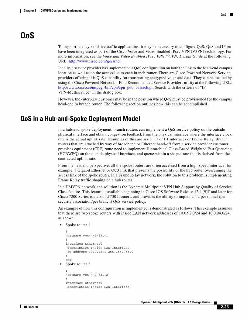
Chapter 2 DMVPN Design and Implementation QoS
QoSTo support latency-sensitive traffic applications, it may be necessary to configure QoS. QoS and IPsec have been integrated as part of the Cisco Voice and Video Enabled IPsec VPN (V3PN) technology. For more information, see the Voice and Video Enabled IPsec VPN (V3PN) Design Guide at the following URL: http://www.cisco.com/go/srnd.
Ideally, a service provider has implemented a QoS configuration on both the link to the head-end campus location as well as on the access-list to each branch router. There are Cisco Powered Network Service providers offering this QoS capability for transporting encrypted voice and data. They can be located by using the Cisco Powered Network—Find Recommended Service Providers utility at the following URL: http://www.cisco.com/pcgi-bin/cpn/cpn_pub_bassrch.pl. Search with the criteria of “IP VPN-Multiservice” in the dialog box.
However, the enterprise customer may be in the position where QoS must be provisioned for the campus head-end to branch router. The following section outlines how this can be accomplished.
QoS in a Hub-and-Spoke Deployment ModelIn a hub-and spoke deployment, branch routers can implement a QoS service policy on the outside physical interface and obtain congestion feedback from the physical interface where the interface clock rate is the actual uplink rate. Examples of this are serial T1 or E1 interfaces or Frame Relay. Branch routers that are attached by way of broadband or Ethernet hand-off from a service provider customer premises equipment (CPE) route need to implement Hierarchical Class-Based Weighted Fair Queueing (HCBWFQ) on the outside physical interface, and queue within a shaped rate that is derived from the contracted uplink rate.
From the headend perspective, all the spoke routers are often accessed from a high-speed interface; for example, a Gigabit Ethernet or OC3 link that presents the possibility of the hub router overrunning the access link of the spoke router. In a Frame Relay network, the solution to this problem is implementing Frame Relay traffic shaping on a hub router.
In a DMVPN network, the solution is the Dynamic Multipoint VPN Hub Support by Quality of Service Class feature. This feature is available beginning in Cisco IOS Software Release 12.4 (9)T and later for Cisco 7200 Series routers and 7301 routers, and provides the ability to implement a per tunnel (per security association/per branch) QoS service policy.
An example of how this configuration is implemented is demonstrated as follows. This example assumes that there are two spoke routers with inside LAN network addresses of 10.0.92.0/24 and 10.0.94.0/24, as shown.
• Spoke router 1
!hostname vpn-jk2-831-1!interface Ethernet0 description Inside LAN Interface ip address 10.0.92.1 255.255.255.0!end
• Spoke router 2
!hostname vpn-jk2-831-2!interface Ethernet0 description Inside LAN Interface
2-25Dynamic Multipoint VPN (DMVPN) 1.1 Design Guide
OL-9024-01

Chapter 2 DMVPN Design and Implementation QoS
ip address 10.0.94.1 255.255.255.0!end
In the head-end configuration to support these branches, each branch has an IP access list configured to match packets destined from any network at the campus to the remote inside LAN network at the respective branch.
!hostname HEAD_END!ip access-list extended B000 permit ip any 10.0.92.0 0.0.0.255ip access-list extended B001 permit ip any 10.0.94.0 0.0.0.255
Also, a class map is configured for each branch to reference the appropriate IP extended access list:
class-map match-all B001-class match access-group name B001class-map match-all B000-class match access-group name B000!
Class maps are defined to identify the traffic to prioritize to each branch:
!class-map match-all VOICE match ip dscp efclass-map match-any CALL-SETUP match ip dscp af31 match ip dscp cs3class-map match-any INTERNETWORK-CONTROL match ip dscp cs6!
These class maps are referenced by the policy map configuration. The VOICE class is configured for nine G.729 voice calls, assuming the downlink to each branch is a Frame Relay or HDLC-encapsulated T1 link from the service provider to the branch router. This is the “child” service policy in an HCBWFQ configuration.
policy-map branch-policy class CALL-SETUP bandwidth percent 2 class INTERNETWORK-CONTROL bandwidth percent 5 class VOICE priority 504 class class-default fair-queue random-detect!
The “parent” service policy in an HCBWFQ configuration is defined. It is assumed that each branch is connected to the service provider at a T1 (1.54 Mbps) data rate. The shaper is configured at a percentage of that rate, in this case 85 percent, to accommodate some degree of jitter in the arrival rate of all packets because of queueing and buffering within the service provider network. The 85 percent example is a conservative value, and can likely be incremented to avoid wasting bandwidth. However, the goal is to never present more packets than the link can handle. Do not configure a shaper value that allows the service provider to drop packets indiscriminately. It is assumed that the service provider has not applied
2-26Dynamic Multipoint VPN (DMVPN) 1.1 Design Guide
OL-9024-01
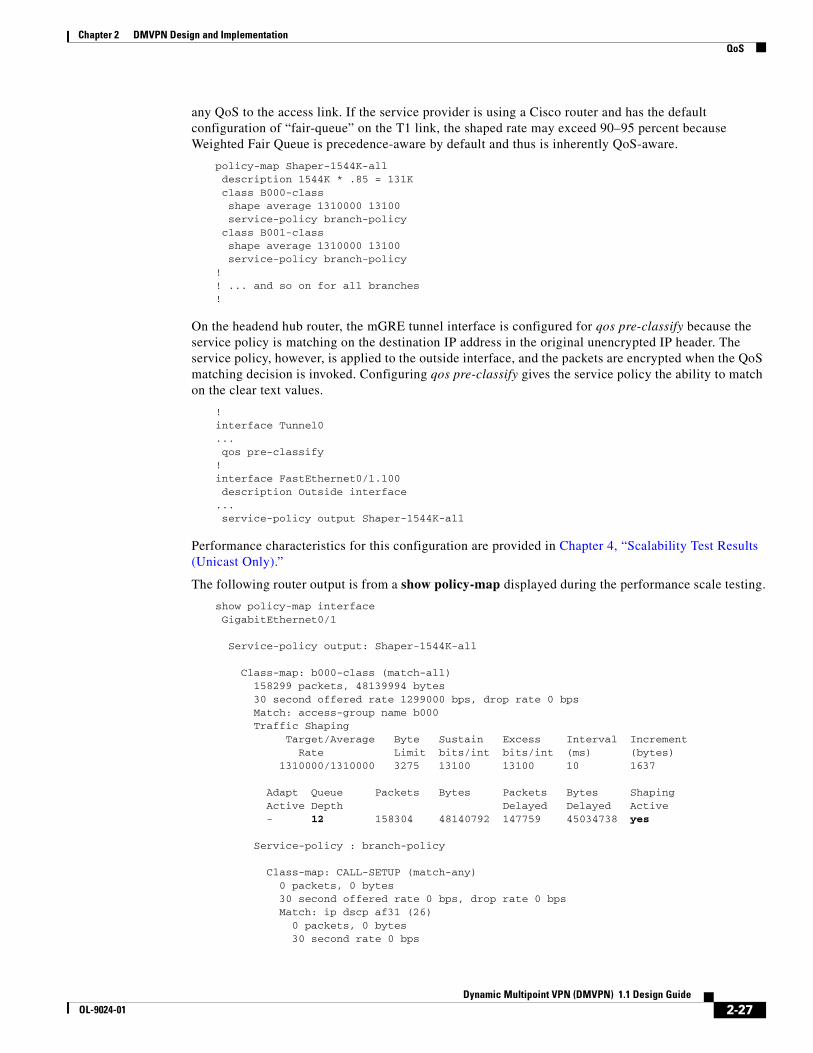
Chapter 2 DMVPN Design and Implementation QoS
any QoS to the access link. If the service provider is using a Cisco router and has the default configuration of “fair-queue” on the T1 link, the shaped rate may exceed 90–95 percent because Weighted Fair Queue is precedence-aware by default and thus is inherently QoS-aware.
policy-map Shaper-1544K-all description 1544K * .85 = 131K class B000-class shape average 1310000 13100 service-policy branch-policy class B001-class shape average 1310000 13100 service-policy branch-policy!! ... and so on for all branches!
On the headend hub router, the mGRE tunnel interface is configured for qos pre-classify because the service policy is matching on the destination IP address in the original unencrypted IP header. The service policy, however, is applied to the outside interface, and the packets are encrypted when the QoS matching decision is invoked. Configuring qos pre-classify gives the service policy the ability to match on the clear text values.
!interface Tunnel0... qos pre-classify!interface FastEthernet0/1.100 description Outside interface... service-policy output Shaper-1544K-all
Performance characteristics for this configuration are provided in Chapter 4, “Scalability Test Results (Unicast Only).”
The following router output is from a show policy-map displayed during the performance scale testing.
show policy-map interface GigabitEthernet0/1
Service-policy output: Shaper-1544K-all
Class-map: b000-class (match-all) 158299 packets, 48139994 bytes 30 second offered rate 1299000 bps, drop rate 0 bps Match: access-group name b000 Traffic Shaping Target/Average Byte Sustain Excess Interval Increment Rate Limit bits/int bits/int (ms) (bytes) 1310000/1310000 3275 13100 13100 10 1637
Adapt Queue Packets Bytes Packets Bytes Shaping Active Depth Delayed Delayed Active - 12 158304 48140792 147759 45034738 yes
Service-policy : branch-policy
Class-map: CALL-SETUP (match-any) 0 packets, 0 bytes 30 second offered rate 0 bps, drop rate 0 bps Match: ip dscp af31 (26) 0 packets, 0 bytes 30 second rate 0 bps
2-27Dynamic Multipoint VPN (DMVPN) 1.1 Design Guide
OL-9024-01

Chapter 2 DMVPN Design and Implementation QoS
Match: ip dscp cs3 (24) 0 packets, 0 bytes 30 second rate 0 bps Queueing Output Queue: Conversation 73 Bandwidth 2 (%) Bandwidth 26 (kbps) Max Threshold 64 (packets) (pkts matched/bytes matched) 0/0 (depth/total drops/no-buffer drops) 0/0/0
Class-map: INTERNETWORK-CONTROL (match-any) 5 packets, 870 bytes 30 second offered rate 0 bps, drop rate 0 bps Match: ip dscp cs6 (48) 5 packets, 870 bytes 30 second rate 0 bps Match: access-group name IKE 0 packets, 0 bytes 30 second rate 0 bps Queueing Output Queue: Conversation 74 Bandwidth 5 (%) Bandwidth 65 (kbps) Max Threshold 64 (packets) (pkts matched/bytes matched) 5/870 (depth/total drops/no-buffer drops) 0/0/0 QoS Set dscp cs6 Packets marked 5
Class-map: VOICE (match-all) 118416 packets, 18709728 bytes 30 second offered rate 502000 bps, drop rate 0 bps Match: ip dscp ef (46) Queueing Strict Priority Output Queue: Conversation 72 Bandwidth 50 (%) Bandwidth 655 (kbps) Burst 16375 (Bytes) (pkts matched/bytes matched) 110494/17458052 (total drops/bytes drops) 0/0
Class-map: class-default (match-any) 39878 packets, 29429396 bytes 30 second offered rate 795000 bps, drop rate 0 bps Match: any Queueing Flow Based Fair Queueing Maximum Number of Hashed Queues 64 (total queued/total drops/no-buffer drops) 6/0/0 exponential weight: 9
class Transmitted Random drop Tail drop Minimum Maximum Mark pkts/bytes pkts/bytes pkts/bytes thresh thresh prob 0 39344/29075840 0/0 0/0 20 40 1/10 1 0/0 0/0 0/0 22 40 1/10 2 536/353824 0/0 0/0 24 40 1/10 3 0/0 0/0 0/0 26 40 1/10 4 0/0 0/0 0/0 28 40 1/10 5 0/0 0/0 0/0 30 40 1/10 6 0/0 0/0 0/0 32 40 1/10 7 0/0 0/0 0/0 34 40 1/10 rsvp 0/0 0/0 0/0 36 40 1/10
2-28Dynamic Multipoint VPN (DMVPN) 1.1 Design Guide
OL-9024-01

Chapter 2 DMVPN Design and Implementation QoS
Class-map: b001-class (match-all) 158223 packets, 48128074 bytes 30 second offered rate 1301000 bps, drop rate 0 bps Match: access-group name b001 Traffic Shaping Target/Average Byte Sustain Excess Interval Increment Rate Limit bits/int bits/int (ms) (bytes) 1310000/1310000 3275 13100 13100 10 1637
Adapt Queue Packets Bytes Packets Bytes Shaping Active Depth Delayed Delayed Active - 8 158231 48130666 148135 45116434 yes
. . . and so on. There is one instance of a shaper and class map for each branch. However the display is terminated for brevity.
Note the following:
• The offered rate of 1299000 bps is approaching the shaper rate of 1310000; the downlink to this branch is fully utilized
• The shaper is engaged in the b000-class, and there are currently 12 packets (queue-depth) queued
• Packets are matched in the VOICE class, the CALL-SETUP has no matches as the test traffic profile does not contain any packets marked CS3/AF31
• The INTERNETWORK-CONTROL has matches, and these packets are EIGRP hello packets
• The default class has matches in both IP Precedence 0 and 2. The traffic profile has both DSCP BE (Best Effort) and DSCP AF21 (IP precedence 2); WRED is enabled and these markings are displayed in the appropriate counters.
QoS in a Spoke-to-Spoke Deployment ModelIn a spoke-to-spoke deployment model, branch routers can also be configured with the Dynamic Multipoint VPN Hub Support by Quality of Service Class feature. Cisco IOS Release 12.4 (9)T or later is required for spokes consisting of Cisco 800, 1700, 1800, 2600XM, 2800, 3700, 3800 Series routers. For Cisco 831 Series spokes, Cisco IOS release 12.3 (11) T10 is required.
The challenge in the spoke-to-spoke model is that traffic is originating from the hub site as well as possibly one or more spoke sites. If the hub site and the spoke sites all configure their QoS shaper at the access link data rate (or some percentage of that rate, as described in the previous section), there is the possibility that the collection of the hub and spokes send sufficient traffic to overrun a single spoke. Determining the appropriate values for both the shapers as well as the priority and bandwidth queues is a challenge at best.
For this reason, a QoS-enabled service provider offering QoS on the access link to the branch or spoke routers is the best possible solution.
IP Multicast IPmc has two areas of concern. The first is the ability to scale the solution such that a large number of listeners may join a stream. The second is the restrictions in functionality required as a result of the point-to-multipoint GRE interface.
Scalability testing with IPmc and IPsec encryption indicates that there are issues with packet loss because of the instant replication of many packets. IPmc replication generates new headers for each of the joined destinations. The payload is not changed. Each packet is referenced as a pointer that links the
2-29Dynamic Multipoint VPN (DMVPN) 1.1 Design Guide
OL-9024-01
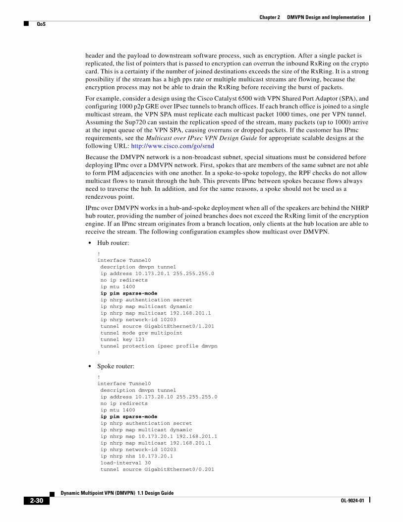
Chapter 2 DMVPN Design and Implementation QoS
header and the payload to downstream software process, such as encryption. After a single packet is replicated, the list of pointers that is passed to encryption can overrun the inbound RxRing on the crypto card. This is a certainty if the number of joined destinations exceeds the size of the RxRing. It is a strong possibility if the stream has a high pps rate or multiple multicast streams are flowing, because the encryption process may not be able to drain the RxRing before receiving the burst of packets.
For example, consider a design using the Cisco Catalyst 6500 with VPN Shared Port Adaptor (SPA), and configuring 1000 p2p GRE over IPsec tunnels to branch offices. If each branch office is joined to a single multicast stream, the VPN SPA must replicate each multicast packet 1000 times, one per VPN tunnel. Assuming the Sup720 can sustain the replication speed of the stream, many packets (up to 1000) arrive at the input queue of the VPN SPA, causing overruns or dropped packets. If the customer has IPmc requirements, see the Multicast over IPsec VPN Design Guide for appropriate scalable designs at the following URL: http://www.cisco.com/go/srnd
Because the DMVPN network is a non-broadcast subnet, special situations must be considered before deploying IPmc over a DMVPN network. First, spokes that are members of the same subnet are not able to form PIM adjacencies with one another. In a spoke-to-spoke topology, the RPF checks do not allow multicast flows to transit through the hub. This prevents IPmc between spokes because flows always need to traverse the hub. In addition, and for the same reasons, a spoke should not be used as a rendezvous point.
IPmc over DMVPN works in a hub-and-spoke deployment when all of the speakers are behind the NHRP hub router, providing the number of joined branches does not exceed the RxRing limit of the encryption engine. If an IPmc stream originates from a branch location, only clients at the hub location are able to receive the stream. The following configuration examples show multicast over DMVPN.
• Hub router:
!interface Tunnel0 description dmvpn tunnel ip address 10.173.20.1 255.255.255.0 no ip redirects ip mtu 1400 ip pim sparse-mode ip nhrp authentication secret ip nhrp map multicast dynamic ip nhrp map multicast 192.168.201.1 ip nhrp network-id 10203 tunnel source GigabitEthernet0/1.201 tunnel mode gre multipoint tunnel key 123 tunnel protection ipsec profile dmvpn!
• Spoke router:
!interface Tunnel0 description dmvpn tunnel ip address 10.173.20.10 255.255.255.0 no ip redirects ip mtu 1400 ip pim sparse-mode ip nhrp authentication secret ip nhrp map multicast dynamic ip nhrp map 10.173.20.1 192.168.201.1 ip nhrp map multicast 192.168.201.1 ip nhrp network-id 10203 ip nhrp nhs 10.173.20.1 load-interval 30 tunnel source GigabitEthernet0/0.201
2-30Dynamic Multipoint VPN (DMVPN) 1.1 Design Guide
OL-9024-01

Chapter 2 DMVPN Design and Implementation Interactions with Other Networking Functions
tunnel mode gre multipoint tunnel key 123 tunnel protection ipsec profile dmvpn!
Interactions with Other Networking FunctionsOther networking functions such as NAT, PAT, DHCP, and firewall considerations apply to designing a DMVPN network. This section describes these functions.
Network Address Translation and Port Address TranslationAlthough NAT and PAT can result in an added layer of security and address conservation, they both present challenges to the implementation of an IPsec VPN. ISAKMP relies on an individual IP address per crypto peer for proper operation. PAT works by masquerading multiple crypto peers behind a single IP address.
The IPsec NAT Traversal feature (NAT-T) introduces support for IPsec traffic to travel through NAT or PAT devices by encapsulating both the IPsec SA and the ISAKMP traffic in a UDP wrapper. NAT-T was first introduced in Cisco IOS version 12.2(13)T and is auto-detected by VPN devices. There are no configuration steps for a Cisco IOS router running this release or later because it is enabled by default as a global command. The NAT-T feature detects a PAT device between the crypto peers and negotiates NAT-T if it is present.
For more information on IPsec NAT-T (also known as transparency), see the following URL: http://www.cisco.com/univercd/cc/td/doc/product/software/ios122/122newft/122t/122t13/ftipsnat.htm
DMVPN designs are compatible with NAT-T in a hub-and-spoke deployment model. Cisco IOS Release 12.3(9a) or 12.3(12)T2 or later is required on both the headend and branch routers to support DMVPN topologies where the headend router is behind NAT.
In spoke-to-spoke designs, NAT is a greater concern. NHRP registrations do not allow spoke-to-spoke crypto sessions to properly form if one spoke is behind a NAT device. In this situation, the IPsec SA does not establish, and the branch continues to send packets to the remote branch via the hub. Depending on the software version, these packets may be process-switched. Because of this, spoke-to-spoke topologies should be avoided when spokes are behind NAT boundaries.
In dual DMVPN cloud topologies, regardless of deployment model, the Single Tier Headend Architecture can be configured with IPsec in transport mode. Although IPsec tunnel mode is generally recommended for DMVPN designs, there are some considerations for running IPsec transport mode with NAT/PAT:
• When the branch sends its NHRP registrations to the headend, the headend sees both the branch outside NAT address and inside host GRE address. The headend selects the outside NAT address from the branch for its use.
• Different branch routers can use the same (overlapping) inside host GRE address, because the outside NAT address is unique.
The Dual Tier Headend Architecture requires the IPsec tunnels to be configured in tunnel mode. Note the following caveats with this configuration:
• The headend router can see only the inside host GRE address of the branch router in the NHRP registrations coming from the branch router.
• Branch routers must therefore have unique inside host GRE address, requiring coordination for all branches in the DMVPN cloud.
2-31Dynamic Multipoint VPN (DMVPN) 1.1 Design Guide
OL-9024-01

Chapter 2 DMVPN Design and Implementation Common Configuration Mistakes
Note As a caveat, IPsec tunnels generated via DMVPN between headend and branch are not supported with the headend behind NAT/PAT when using the Cisco Catalyst 6500 or Cisco 7600 with VPNSM. If this is a design requirement, Cisco recommends using the Cisco 7200VXR or other Cisco IOS router at the headend.
In the event that there is more than one branch router behind a single NAT device, DMVPN can only support this configuration if the NAT device translates each branch router to a unique outside NAT IP address.
Firewall ConsiderationsThis section discusses the various firewall considerations when implementing a DMVPN design.
Headend or Branch
Depending on the crypto and DMVPN headend or branch placements, the following protocols and ports are required to be allowed:
• UDP Port 500—ISAKMP as source and destination
• UDP Port 4500—NAT-T as a destination
• IP Protocol 50—ESP
• IP Protocol 51—AH (if AH is implemented)
• IP Protocol 47—GRE
Network location of the crypto headend in relation to the headend firewall(s) impacts both the accessibility and performance of both systems. The network manager must ensure that all firewalls are properly configured to allow the tunnel traffic bi-directionally. The crypto headend must be accessible to the branch router because all crypto sessions are initiated by the branch router.
Crypto Access Check
DMVPN may use tunnel profiles, which eliminate the need to statically define crypto ACLs that would normally be used to match packets that require encryption. However, this functionality is still handled by the software dynamically. The show crypto map Cisco IOS command can be used to view the access list that is generated. The access list matches the GRE packet from the tunnel endpoints. If the encryption and the GRE tunnel are not using the same endpoints, tunnel profiles cannot be used, and crypto access lists or dynamic crypto maps must be configured. The access list should reflect the crypto endpoints and not the GRE endpoints. This configuration is required when implementing a Dual Tier Headend Architecture.
Common Configuration MistakesThe following sections discuss common mistakes and problems encountered when configuring DMVPN.
2-32Dynamic Multipoint VPN (DMVPN) 1.1 Design Guide
OL-9024-01

Chapter 2 DMVPN Design and Implementation Common Configuration Mistakes
Advertising Tunnel Endpoints in the Routing ProtocolIt is possible to include the tunnel endpoints in the internal routing protocol. In this case, the headend address is typically a globally-routed address on the public Internet. Although not a best practice, this address may also be advertised internally. In this situation, the DMVPN subnet initially works properly, but after routing has converged, the branch may attempt to reach the headend public address via the DMVPN tunnel rather than the outside interface. This causes the tunnel to fail and consequently the routing protocol to stop advertising the public address, allowing the DMVPN tunnel to once again function correctly. The process repeats continually, and is sometimes referred to as “recursive routing”.
IPsec Transform Set MatchesAt least one matching IPsec transform set must be configured between two crypto peers. When specifying a particular strength of encryption algorithm, a common strength encryption algorithm and transform set should also be configured on both the headend and branches. Failure to do so prevents the IPsec tunnel from starting.
ISAKMP Policy MatchingThere is a default ISAKMP policy present in all Cisco IOS devices. This default is encryption DES, HMAC of SHA, IKE Authentication of RSA signature, and DH group 1. If a stronger ISAKMP policy is desired, both sides must support the policy.
It is common, but not required, to use the same encryption level transform set and hash methods in the ISAKMP policy and IPsec transform set.
2-33Dynamic Multipoint VPN (DMVPN) 1.1 Design Guide
OL-9024-01

DOL-9024-01
C H A P T E R3
Scalability ConsiderationsThis chapter presents the following steps to selecting Cisco products for a VPN solution:
• Sizing the headend
• Choosing Cisco products that can be deployed for headend devices
• Product sizing and selection information for branch devices
General Scalability ConsiderationsThis section provides general scalability considerations to assist with design requirements.
IPsec Encryption ThroughputThe throughput capacity of the IPsec encryption engine in each platform (headend or branch) must be considered for scalable designs, because each packet that is encrypted must traverse through the encryption engine. Therefore, encryption throughput must consider bi-directional speeds. Several examples are shown in Table 3-1 and Table 3-2 for popular headend and branch connection speeds.
Table 3-1 Headend Connection Speeds
Connection TypeSpeed(in Mbps)
Encryption Throughput Required (in Mbps)
T3/DS3 44.7 90.0
OC3 155.0 310.0
OC12 622.0 1250.0
Table 3-2 Branch Connection Speeds
Connection TypeSpeed(in Mbps)
Encryption Throughput Required (in Mbps)
T1 1.5 3.0
2 x T1 3.0 6.0
3-1ynamic Multipoint VPN (DMVPN) 1.1 Design Guide

Chapter 3 Scalability Considerations General Scalability Considerations
In general, as throughput increases, the burden on router CPU also increases. However, with hardware-accelerated encryption available for all Cisco router products from the 871 through the 7600, impact to the main CPU is offloaded to the VPN hardware. However, main router CPU processing still occurs, so higher throughput typically results in higher CPU consumption.
Packets Per Second—Most Important FactorAlthough bandwidth throughput capacity must be considered, the packet rate for the connection speeds being terminated or aggregated is more important.
In general, routers and encryption engines have upper boundaries for processing a given number of packets per second (pps). The size of packets used for testing and throughput evaluations can understate or overstate true performance. For example, if a router with a VPN module can handle 20 Kpps, 100-byte packets lead to 16 Mbps throughput while 1400-byte packets at the same packet rate lead to 224 Mbps.
Because of such a wide variance in throughput, pps is generally a better parameter to determine router forwarding potential than bits per second (bps). Scalability of the headend is the aggregate forwarding potential of all branches that terminate a tunnel to that headend. Therefore, the aggregate pps from all branches impacts the pps rate of that headend.
Tunnel Quantity Affects ThroughputAlthough throughput is highly dependent on platform architecture, as tunnel quantities are increased, the overall throughput generally tends to decrease. When a router receives a packet from a different peer than the peer whose packet was just decrypted, a lookup based on the security parameters index (SPI) of the new packet must be performed. The transform set information and negotiated session key of the new packet is then loaded into the hardware decryption engine for processing. Having traffic flowing on a larger numbers of SAs tends to negatively affect throughput performance.
Increasingly, platforms with hardware-accelerated IPsec encryption are designed to offload tunnel processing overhead as well, resulting in more linear performance regardless of the number of tunnels. For example, the VPN SPA blade for the Cisco 7600 has fairly linear throughput regardless of whether the traffic load is offered on a few tunnels or several thousand.
GRE Encapsulation Affects ThroughputRouter encryption throughput is affected by the configuration of GRE. In addition to the headers that are added to the beginning of each packet, these headers also must be encrypted. The GRE encapsulation process, when not hardware-accelerated, increases total CPU utilization. Total throughput in a DMVPN design results in a lower throughput than that of an IPsec Direct Encapsulation design.
T3/DS3 44.7 90.0
Broadband cable/DSL 384 Kbps uplink/ 2 Mbps downlink
2.4
Table 3-2 Branch Connection Speeds (continued)
3-2Dynamic Multipoint VPN (DMVPN) 1.1 Design Guide
OL-9024-01

Chapter 3 Scalability Considerations Scalable Dual DMVPN Cloud Topology—Hub-and-Spoke Deployment Model
Routing Protocols Affect CPU OverheadCPU overhead is affected by running a routing protocol. The processing of keepalives or hello packets and maintenance of a routing table uses a finite amount of CPU time. This amount varies with the number of routing peers and the size of the routing table. The network manager should design the routing protocol based on widely-known accepted practices for that particular routing protocol.
Scalable Dual DMVPN Cloud Topology—Hub-and-Spoke Deployment Model
This section discusses headend and branch scalability for the dual DMVPN cloud topology with the hub-and-spoke deployment model.
Headend ScalabilityThis section describes the various headend scalability factors to consider in a dual DMVPN cloud topology with the hub-and-spoke deployment model.
Tunnel Aggregation Scalability
The maximum number of IPsec tunnels that a headend can terminate must be considered. Tunnel scalability is a function of the number of branch routers that are terminated to the headend aggregation point. This number must include both the primary tunnels as well as any alternate tunnels that each headend may be responsible for in the event of a failover situation.
The number of IPsec tunnels that can be aggregated by a platform is used as the primary determining factor in recommending a platform. Equally or more important is the encryption pps rate.
Aggregation Scalability
Aside from the number of tunnels that a headend terminates, the aggregated pps must be considered. Requirements are influenced by several factors, including the following:
• Headend connection speed—What is the speed of the WAN link on which the IPsec tunnels of the branch routers are transported through at the headend (DS3, OC3, OC12, or other)?
• Branch connection speeds—What is the typical bandwidth at each branch office (fractional-T1, T1, T3, broadband DSL/cable, or other)?
• Expected utilization—What is the maximum utilization of the WAN bandwidth under normal operation (or perhaps peak, depending on customer requirements)?
The pps rate (traffic size and traffic mix) is the largest single factor in router scalability.
Customer Requirement Aggregation Scalability Case Studies
This section includes examples to illustrate headend scalability factors.
3-3Dynamic Multipoint VPN (DMVPN) 1.1 Design Guide
OL-9024-01

Chapter 3 Scalability Considerations Scalable Dual DMVPN Cloud Topology—Hub-and-Spoke Deployment Model
Customer Example—1000 Branches
Assume that a customer has the following requirements:
• Number of branch offices—1000
• Branch access speeds—384k/1.5M cable/DSL
• Headend access speed—OC12 (622 Mbps)
• Expected utilization—33 percent
The calculation of aggregate bandwidth requirements is as follows:
• typical case—1000 x (384kbps + 1.5 Mbps) x 33 percent utilization = 628 Mbps
• worst case—1000 x (384kbps + 1.5 Mbps) x 100 percent utilization = 1.9 Gbps
Possible design options are to recommend a series of stacked Cisco 7200VXR platforms. At least four are required to aggregate 1000 tunnels; however, this does not provide the needed aggregate bandwidth of at least 628 Mbps.
A design alternative is to recommend a pair of Cisco 7600 routers, each with Sup720 and VPN SPA, as shown in Figure 3-1. The VPN SPAs each provide up to 1.2 Gbps of encryption performance, so the design can support up to OC12 connection speeds at each headend.
Figure 3-1 Cisco 7600-Based DMVPN Design
148771
500 spokes 500 spokes
4 DMVPNs
Uniquepublic IP
addressesper mGRE
Cisco 7600Sup720
VPN SPA
OC3, OC12
Up to 1000Branches
T1, T3,DSL/Cable
PrimarySecondary
Cisco 7600Sup720
VPN SPA
OC3, OC12
DMVPN DMVPN DMVPNDMVPN
Cisco 1800 ISR Cisco 2800 ISR Cisco 3800 ISR
3-4Dynamic Multipoint VPN (DMVPN) 1.1 Design Guide
OL-9024-01

Chapter 3 Scalability Considerations Scalable Dual DMVPN Cloud Topology—Hub-and-Spoke Deployment Model
Although the VPN SPA can handle up to 5000 IPsec tunnels, as well as 1000 accelerated GRE tunnels, accelerated mGRE is not currently supported. This is primarily because of the lack of support for the mGRE tunnel key, which adds an extra four-byte field to the GRE packet header. However, there is a workaround to take advantage of the accelerated GRE functionality in the VPN SPA.
The mGRE tunnel key is used to distinguish to which DMVPN cloud the packet belongs when multiple DMVPN clouds are configured on the same router. Another way to differentiate DMVPN clouds is to allocate a unique public IP address to each mGRE interface. The remote routers can then connect to their assigned mGRE interface and use the IP address instead of the tunnel key to designate which DMVPN cloud is the destination on the headend. In this way, you can still take advantage of the IPsec acceleration on the VPN SPA, with the Sup720 processing the mGRE.
The design shown above can then support up to 1000 branch offices. Routing peers tend to be the limiting factor. On the Cisco 7200VXR platform, routing peers tend to be limited to 500–700. On the Cisco 7600 with Sup720, up to 1000 routing peers have been proven to work in the Cisco scalability test lab.
Customer Example—5000 Branches
Assume that a customer has the following requirements:
• Number of branch offices—5000
• Branch access speeds—128 Kpps/1 Mbps DSL
• Headend access speed—OC12 (622 Mbps)
• Expected utilization—25 percent
The calculation of aggregate bandwidth requirements is as follows:
• typical case—1000 x (128kbps + 1 Mbps) x 25 percent utilization = 1.24 Gbps
• worst case—1000 x (128kbps + 1Mbps) x 100 percent utilization = 5.64 Gbps
Currently, no Cisco platform can aggregate 5000 DMVPN tunnels on a single box. Options for such large designs include the following:
• Duplicating a smaller scale design, such as either the Cisco 7200VXR-based design for 500–700 branch spokes, or the Cisco 7600-based design for 1000 spokes.
• Implementing a dual tier architecture using the Cisco 7200VXR platform to terminate the mGRE connections, and the Cisco 7600 platform for high-capacity IPsec encryption.
The dual tier architecture is shown in Figure 3-2.
3-5Dynamic Multipoint VPN (DMVPN) 1.1 Design Guide
OL-9024-01
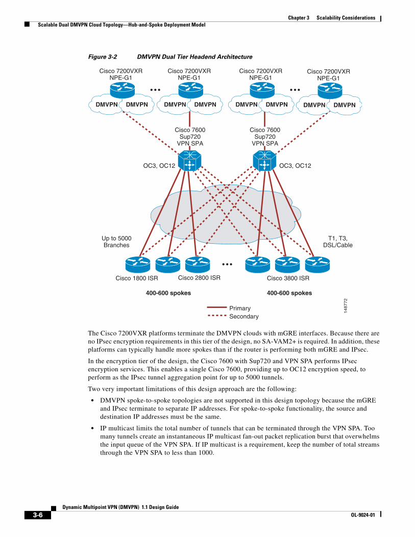
Chapter 3 Scalability Considerations Scalable Dual DMVPN Cloud Topology—Hub-and-Spoke Deployment Model
Figure 3-2 DMVPN Dual Tier Headend Architecture
The Cisco 7200VXR platforms terminate the DMVPN clouds with mGRE interfaces. Because there are no IPsec encryption requirements in this tier of the design, no SA-VAM2+ is required. In addition, these platforms can typically handle more spokes than if the router is performing both mGRE and IPsec.
In the encryption tier of the design, the Cisco 7600 with Sup720 and VPN SPA performs IPsec encryption services. This enables a single Cisco 7600, providing up to OC12 encryption speed, to perform as the IPsec tunnel aggregation point for up to 5000 tunnels.
Two very important limitations of this design approach are the following:
• DMVPN spoke-to-spoke topologies are not supported in this design topology because the mGRE and IPsec terminate to separate IP addresses. For spoke-to-spoke functionality, the source and destination IP addresses must be the same.
• IP multicast limits the total number of tunnels that can be terminated through the VPN SPA. Too many tunnels create an instantaneous IP multicast fan-out packet replication burst that overwhelms the input queue of the VPN SPA. If IP multicast is a requirement, keep the number of total streams through the VPN SPA to less than 1000.
148772
400-600 spokes 400-600 spokes
OC3, OC12
Up to 5000Branches
T1, T3,DSL/Cable
PrimarySecondary
OC3, OC12
DMVPN DMVPN
Cisco 7600Sup720
VPN SPA
Cisco 7600Sup720
VPN SPA
Cisco 1800 ISR Cisco 2800 ISR Cisco 3800 ISR
Cisco 7200VXRNPE-G1
DMVPN DMVPN
Cisco 7200VXRNPE-G1
DMVPN DMVPN
Cisco 7200VXRNPE-G1
DMVPN DMVPN
Cisco 7200VXRNPE-G1
3-6Dynamic Multipoint VPN (DMVPN) 1.1 Design Guide
OL-9024-01

Chapter 3 Scalability Considerations Scalable Dual-DMVPN Cloud Topology—Spoke-to-Spoke Designs
Branch Office ScalabilityThe branch routers are primarily responsible for the following:
• Terminating p2p GRE over IPsec or mGRE tunnels from the headend routers
• Running a routing protocol inside of the GRE tunnels to advertise internal routes
The most important factors to consider when choosing a product for the branch office include the following:
• Branch access speed and expected traffic throughput to the headend (for example, fractional T1, T1, T3, broadband cable/DSL)
• Other services provided by the branch router (for example, DHCP, NAT/PAT, VoIP, Cisco IOS firewall, IOS-IPS)
The pps rate (traffic size and traffic mix) is the largest single factor in branch router scalability.
The number of p2p GRE over IPsec tunnels does not play a large role in the branch sizing because each branch router must be able to terminate a single set of tunnels (primary and secondary) for this design in a hub-and-spoke model.
A primary concern is the amount of traffic throughput (pps and bps) along with the corresponding CPU utilization. Cisco recommends that branch routers be chosen so that CPU utilization does not exceed 65 percent under normal operational conditions. The branch router must have sufficient CPU cycles to service periodic events that require processing. Examples include ISAKMP and IPsec SA establishing and re-keying, SNMP, SYSLOG activities, as well as local CLI exec processing.
After initial deployment and testing, it may be possible to run branch routers at CPU utilization levels higher than 65 percent under normal operational conditions. However, this design guide conservatively recommends staying at or below 65 percent.
The Cisco Integrated Services Router (ISR) 1840, 2800, and 3800 Series of products have higher CPU performance than the products they replace. The ISR has an encryption module on the motherboard, and can be upgraded to an AIM series of encryption module for increased crypto performance.
Scalable Dual-DMVPN Cloud Topology—Spoke-to-Spoke Designs
Scalable spoke-to-spoke designs are a little more complicated to achieve. To begin with, to achieve resiliency in the design, Cisco recommends that each branch router have a link to two headends. In a dual DMVPN topology, each cloud has a single headend. Routing is used to determine the primary cloud. Headend load balancing can be achieved when a headend router serves two clouds; one being used as a primary for a set of branches and the other as a secondary for a different set of branches. This method allows additional headend routers to be added if more DMVPN clouds are needed to attach additional branch routers to the network.
The drawback of this approach is that spoke-to-spoke sessions are not allowed over different DMVPN clouds. This would require a single large DMVPN cloud for the primary connections and a second single DMVPN cloud that would be used if the primary failed. Building a large DMVPN cloud requires the headend routers to be daisy-chained. To build spoke-to-spoke tunnels between branches located on different headends, the headends must have NHRP maps to each other, just as the branches have NHRP maps to the headends. Consider the case where three headend routers are daisy-chained into a single DMVPN cloud, as shown in Figure 3-3.
3-7Dynamic Multipoint VPN (DMVPN) 1.1 Design Guide
OL-9024-01

Chapter 3 Scalability Considerations Scalable Dual-DMVPN Cloud Topology—Spoke-to-Spoke Designs
Figure 3-3 Scaling the Single DMVPN Cloud
Note the following:
• Groups of spokes are mapped to different hubs as primary and secondary, as indicated by the orange and grey lines. Because each hub has only one mGRE interface to aggregate the primary and secondary tunnels from the spokes, the spoke fan-out is limited to 175 routers per group (totaling 350 spokes per hub).
• The hubs have NHRP maps to each other, as indicated by the blue and dark red lines.
• Intra-hub communications must flow over mGRE tunnels.
• Hubs must be routing peers of each other over the mGRE tunnels.
Note the hub configurations snippets below, with the relevant NHRP and NHS commands in italics:
• Hub1 router:
version 12.3!hostname Hub1! crypto ipsec transform-set ENTERPRISE esp-3des esp-sha-hmac mode transport!crypto ipsec profile VPN-DMVPN set transform-set ENTERPRISE!interface Tunnel0 description mGRE Template Tunnel bandwidth 1000 ip address 10.0.0.1 255.255.240.0 ip mtu 1400 no ip next-hop-self eigrp 1
9252
6
175 Spokes 175 Spokes 175 Spokes
Hub 3Hub 2Hub 1
Intra-hub
NHRP Maps
Primary
SecondaryVPN Links
3-8Dynamic Multipoint VPN (DMVPN) 1.1 Design Guide
OL-9024-01

Chapter 3 Scalability Considerations Scalable Dual-DMVPN Cloud Topology—Spoke-to-Spoke Designs
ip nhrp authentication cisco123 ip nhrp map 10.0.0.2 172.16.0.5 ip nhrp map multicast 172.16.0.5 ip nhrp map 10.0.0.3 172.16.0.9 ip nhrp map multicast 172.16.0.9 ip nhrp map multicast dynamic ip nhrp network-id 100000 ip nhrp holdtime 600 ip nhrp nhs 10.0.0.2 no ip split-horizon eigrp 1 tunnel source FastEthernet0/0 tunnel mode gre multipoint tunnel key 100000 tunnel protection ipsec profile VPN-DMVPN!interface FastEthernet0/0 description Outside Interface ip address 172.16.0.1 255.255.255.252!
• Hub2 router:
version 12.3!hostname Hub2! crypto ipsec transform-set ENTERPRISE esp-3des esp-sha-hmac mode transport!crypto ipsec profile VPN-DMVPN set transform-set ENTERPRISE!interface Tunnel0 description mGRE Template Tunnel bandwidth 1000 ip address 10.0.0.2 255.255.240.0 ip mtu 1400 no ip next-hop-self eigrp 1 ip nhrp authentication cisco123 ip nhrp map 10.0.0.1 172.16.0.1 ip nhrp map multicast 172.16.0.1 ip nhrp map 10.0.0.3 172.16.0.9 ip nhrp map multicast 172.16.0.9 ip nhrp map multicast dynamic ip nhrp network-id 100000 ip nhrp holdtime 600 ip nhrp nhs 10.0.0.3 no ip split-horizon eigrp 1 tunnel source FastEthernet0/0 tunnel mode gre multipoint tunnel key 100000 tunnel protection ipsec profile VPN-DMVPN!interface FastEthernet0/0 description Outside Interface ip address 172.16.0.5 255.255.255.252!
• Hub3 router:
version 12.3!hostname Hub3!
3-9Dynamic Multipoint VPN (DMVPN) 1.1 Design Guide
OL-9024-01

Chapter 3 Scalability Considerations Scalable Dual-DMVPN Cloud Topology—Spoke-to-Spoke Designs
crypto ipsec transform-set ENTERPRISE esp-3des esp-sha-hmac mode transport!crypto ipsec profile VPN-DMVPN set transform-set ENTERPRISE!interface Tunnel0 description mGRE Template Tunnel bandwidth 1000 ip address 10.0.0.3 255.255.240.0 ip mtu 1400 no ip next-hop-self eigrp 1 ip nhrp authentication cisco123 ip nhrp map 10.0.0.2 172.16.0.5 ip nhrp map multicast 172.16.0.5 ip nhrp map 10.0.0.1 172.16.0.1 ip nhrp map multicast 172.16.0.1 ip nhrp map multicast dynamic ip nhrp network-id 100000 ip nhrp holdtime 600 ip nhrp nhs 10.0.0.1 no ip split-horizon eigrp 1 tunnel source FastEthernet0/0 tunnel mode gre multipoint tunnel key 100000 tunnel protection ipsec profile VPN-DMVPN!interface FastEthernet0/0 description Outside Interface ip address 172.16.0.9 255.255.255.252!
NHRP maps between hubs are bi-directional (1->2, 2->1, 2->3, 3->2, 3->1, 1->3), as shown in the configurations. Additionally, the hubs must point to each other as next-hop servers, which is done in a daisy-chain fashion (1->2, 2->3, 3->1), as shown in Figure 3-4.
Figure 3-4 Single DMVPN Cloud NHS Daisy Chain
With an NHS daisy-chain deployed in this manner, a multi-hub design is subject to a single point of failure. If one hub is lost, no spoke-to-spoke tunnel setups between spokes connected to the surviving hubs are possible. A more resilient design is shown in Figure 3-5.
9252
7
Hub 3Hub 2Hub 1
Intra-hub NHSDesignations
3-10Dynamic Multipoint VPN (DMVPN) 1.1 Design Guide
OL-9024-01

Chapter 3 Scalability Considerations Scalable Dual-DMVPN Cloud Topology—Spoke-to-Spoke Designs
Figure 3-5 Single DMVPN Cloud with Primary/Secondary Hubs
In this design, hub routers are deployed in pairs, and operate in a dedicated primary or secondary role, allowing the spoke fan-out to be 350 spokes per hub. All hubs are NHRP-mapped to each other, creating bi-directional paths within the DMVPN for the routing updates to traverse and, as before, all hubs are routing peers or neighbors with each other. With regard to the next-hop server mappings, in this design, all routers belong to a primary daisy chain, with a secondary daisy chain connecting routers serving the primary or secondary role in each hub group, as shown in Figure 3-6.
9252
8
350 Spokes 350 Spokes 350 Spokes
Intra-hub
HubGroup
1
HubGroup
2
HubGroup
3
NHRP Maps
Primary
SecondaryVPN Links
3-11Dynamic Multipoint VPN (DMVPN) 1.1 Design Guide
OL-9024-01

Chapter 3 Scalability Considerations Scalable Dual-DMVPN Cloud Topology—Spoke-to-Spoke Designs
Figure 3-6 Dual DMVPN with NHS Daisy Chain
In this design, if a spoke must failover to its secondary hub router, it can still find a path through the secondary NHS daisy chain to open a spoke-to-spoke tunnel to a spoke homed in a different hub group.
Regional Spoke-to-Spoke ClustersAnother option for a very large DMVPN network with spoke-to-spoke requirements, especially one which covers a large geographic area, is to group local spokes into smaller, regional groups, with hubs connected by dedicated high-speed links, as shown in Figure 3-7.
9252
9
Primary NHS Daisy-chain1->2->3->4->5->6->1
HubGroup
1
HubGroup
2
HubGroup
3
Secondary NHS Daisy-chain1->3->5->12->4->6->2
3-12Dynamic Multipoint VPN (DMVPN) 1.1 Design Guide
OL-9024-01

Chapter 3 Scalability Considerations Scalable Dual-DMVPN Cloud Topology—Spoke-to-Spoke Designs
Figure 3-7 Regional Spoke-to-Spoke Clusters
If spoke-to-spoke response time is important, it may be more advantageous to go spoke-hub-hub-spoke, when the two hubs are connected via a high-speed link, than to send traffic via a spoke-to-spoke connection over a long distance via the Internet. In this type of design, the hub devices in the different clusters are connected via any type of IP transport.
Additional Spoke-to-Spoke Design Considerations and CaveatsThe ability to create dynamic spoke-to-spoke IPsec tunnels can create the potential for operational problems in the network. As mentioned before, the spoke-to-spoke tunnels do not create routing peers in the network, eliminating concerns about full mesh routing. Other problems can exist, however, which this section examines briefly.
ResiliencySpoke-to-spoke tunnels are not as resilient to some forms of failure as spoke-to-hub tunnels. Because a routing protocol is not run through the tunnel, a spoke-to-spoke tunnel may fail, with no awareness by the endpoints, allowing traffic to be black-holed. Even ISAKMP keepalives (if configured) may succeed when the encrypted data tunnel is down, and it may take the endpoints an unacceptably long period of time to respond to the loss of the spoke-to-spoke path and resume use of the spoke-hub-spoke path.
Path SelectionThe path that a spoke-to-spoke tunnel takes through a public infrastructure, such as the Internet, may actually be slower than a spoke-to-hub-to-spoke path. DMVPN has no way of measuring the delay incurred on the spoke-to-spoke path and adjusting its choice of path because of poor response time or other network quality degradation.
350 Spokes
SAN JOSE
WASHINGTON, DC
SAN JOSE
350 Spokes
WASHINGTON, DC
9253
0
3-13Dynamic Multipoint VPN (DMVPN) 1.1 Design Guide
OL-9024-01

Chapter 3 Scalability Considerations Scalable Dual-DMVPN Cloud Topology—Spoke-to-Spoke Designs
Overloading of Spoke RoutersThere are no foolproof mechanisms to prevent a spoke from being overrun by incoming traffic from multiple remote spokes. Especially because spoke routers are likely to be the smaller routers (that is, less powerful CPU), it is possible that multiple tunnel setups can cause operational problems for the spoke device if too many other spokes attempt to create tunnels with it. Two Cisco IOS features (first introduced in IOS 12.3(8)T) help alleviate this situation: IKE Call Admission Control (CAC) and System CAC. The first limits the number of ISAKMP SAs the router can set up, based on an absolute value. The second limits the number of SAs based on the usage of system resources.
IKE CAC is configured as follows on the router:
Spoke1#crypto call admission limit ike sa 25
In this example, the number of ISAKMP SAs is limited to 25. The router rejects new SA requests after there are 25 active ISAKMP SAs. The state of IKE CAC can be monitored with the show crypto call admission statistics command.
System CAC is configured as follows on the router:
Spoke1#call admission limit 80
In this example, the router drops new SA requests when 80 percent of system resources are being used. The state of System CAC can be monitored with the show call admission statistics command.
A further problem for spoke-to-spoke designs, not addressed by the CAC feature, is simply the overloading of spoke bandwidth by multiple concurrent spoke-to-spoke IPsec tunnels, which may occur even if the IKE authentication of the ISAKMP SA or system resource limits have not been reached. (See Figure 3-8.)
Figure 3-8 Spoke Router Bandwidth Overloading
In this example, Spoke 2 has a 2 Mbps connection to the Internet. It has existing spoke-to-spoke tunnels established with Spoke 1 and Spoke 5. It has not exceeded either its hard-configured IKE CAC or System CAC limits, but traffic on the existing tunnels with the other two spokes has completely consumed the 2 Mbps bandwidth. Spoke 3 attempts to set up a spoke-to-spoke tunnel with Spoke 2. There is enough
9253
1Hub-and-spoke tunnel
HUB
Spoke 2
Spoke 1
Spoke 3Spoke 4
Spoke 5
Spoke-to-spoke tunnel
Bandwidth = 2Mbps
3-14Dynamic Multipoint VPN (DMVPN) 1.1 Design Guide
OL-9024-01

Chapter 3 Scalability Considerations Scalable Dual-DMVPN Cloud Topology—Spoke-to-Spoke Designs
bandwidth available for the NHRP requests and ISAKMP and IPsec session establishment to occur, but after the tunnel is up, there is not enough bandwidth to send and receive application traffic. The problem here is that there simply is no way for Spoke 2 to tell Spokes 1 and 5 to throttle back their data flows to share the 2 Mbps access link fairly. Upper layer protocols such as UDP or TCP eventually adapt; however, RTP has no flow control mechanism. This is part of the greater QoS dilemma discussed earlier.
At this time, the only workarounds to the problems of bandwidth overloading are the following:
• Designing the network with adequate bandwidth for the anticipated application load
• Balancing the percentage of spoke-to-hub and spoke-to-spoke flows to a reasonable level; the design recommendation is 80 percent hub-to-spoke and 20 percent spoke-to-spoke
• Setting user expectations of the response time and availability of the link appropriately
3-15Dynamic Multipoint VPN (DMVPN) 1.1 Design Guide
OL-9024-01

DOL-9024-01
C H A P T E R4
Scalability Test Results (Unicast Only)This chapter provides Cisco test results to provide design guidance on the scalability of various platforms in DMVPN configurations.
Note IP multicast (IPmc) results are not included.
Figure 4-1 shows the scalability test bed network diagram.
4-1ynamic Multipoint VPN (DMVPN) 1.1 Design Guide

Chapter 4 Scalability Test Results (Unicast Only)
Figure 4-1 DMVPN Hub-And-Spoke Mode Test Bed
1481
86
ISPNetwork
vpn6-2948G-1
VPN Solution Testbed
vpn10-2948G-1
vpn5-2948GL2- 1
vpn4-2948GL2
vpn2-6500-1vpn2-7200-1or
vpn6-7600-1
vpn3-7505-1
"Core / Campus endpoints"Sun Netras: vpn4-n1 through
vpn4-n30Chariot Endpoints
Chariot Console
vpn3-7505-2
vpn6-2600-1through
vpn6-2600-30
vpn7-2948G-1
vpn8-2948G-1
vpn9-2948G-1
vpn7-2600-1through
vpn7-2600-30
vpn8-2600-1through
vpn8-2600-30
vpn9-2600-1through
vpn9-2600-30
Si
vpn10-2600-1through
vpn10-2600-30
ChariotEndpoints
"Branch endpoints"Sun Netras: vpn5-n1 through
vpn5-n30
vpn2-6500-2
vpn11-2948G-1
vpn12-2948G-1
ci13-2948G-1
vpn11-2600-1through
vpn11-2600-30
vpn12-2600-1through
vpn12-2600-30
vpn13-3640-1-5vpn13-3660-1-5
vpn14-2948G-1
vpn2-7200-2or
vpn6-7600-1
Si
vpn13-800 - 1-5vpn13-1700-1-5vpn13-2600-1-5vpn13-3640-1-5
4-2Dynamic Multipoint VPN (DMVPN) 1.1 Design Guide
OL-9024-01

Chapter 4 Scalability Test Results (Unicast Only) Scalability Test Methodology
Scalability Test MethodologyThe headend scalability test bed consists of a number of Cisco branch routers (various types, including the 1700, 2600, 3600, 3700, 1800, 2800, and 3800 Series) homed to various types of headends. For most of the traffic sent through the network, flows are established using the Ixia Chariot testing tool. The bps mix of traffic is approximately 35 percent UDP and 65 percent TCP; application types represented in the mix include the following: VoIP, FTP, DNS, HTTP, POP3, and TN3270. The average packet size is 188 bytes, from headend to branch, and 144 bytes from branch to headend. This relatively small average packet size ensures that the scalability results presented support a converged network design, and tends to be fairly conservative. A network carrying data-only traffic, with a larger average packet size, may achieve better bps performance than that listed here. However, the pps performance given a specific CPU value should be the same.
Some traffic is also generated by the Cisco IP SLA feature in Cisco IOS, formerly known as Cisco Service Assurance Agent (SAA), using the HTTP Get script, with the branch routers making an HTTP Get call to an HTTP server in the core. Testing was conducted without fragmentation occurring in the network by setting the MTU to 1300 bytes on the test endpoints.
The following tables show results for testing with a configuration for the DMVPN tunnel aggregation. The routing protocol used during testing was EIGRP unless otherwise stated. The traffic mix used, as stated earlier, is converged data and g.729 VoIP.
DMVPN—Hub-and-Spoke Deployment Model
Headend Scalability Test ResultsTable 4-1 shows results for scalability testing with a configuration for the DMVPN hub-and-spoke deployment model. QoS is not enabled on the DMVPN head-end hub router, but rather on the WAN routers.
Table 4-1 Headend Scalability Results—DMVPN Hub-and-Spoke Model
Platform # of Tunnels# Voice Calls
Throughput (kpps)
Throughput (Mbps) CPU%
Cisco 7200VXR NPE-G1 Dual SA-VAM2
400 (1 mGRE) 285 47.5 106.3 80%
800 (2 mGRE) 250 45.2 104.3 82%
Cisco 7200VXR NPE-G2 with VPN Services Adapter
600 (1 mGRE) 600 122 416 75%
Cisco ASR 1004 with RP1 and ESP 10
1000 (1 mGRE) 2570 545 1.2 Gbps N/A
4-3Dynamic Multipoint VPN (DMVPN) 1.1 Design Guide
OL-9024-01

Chapter 4 Scalability Test Results (Unicast Only) DMVPN—Hub-and-Spoke Deployment Model
Note No CPU numbers are reported for the Cisco ASR 1000 and Cisco 7600 because, for these case, encryption is done in hardware and has no impact on the main processor.
Table 4-2 shows results for scalability testing with a configuration for the DMVPN hub-and-spoke deployment model. QoS is enabled on the DMVPN headend hub router on the outside physical interface; a GigEthernet in this test. A shaper is configured per branch, qos pre-classify is enabled on the tunnel interface, and the service policy on the outside physical interface matches on the destination IP address. Each branch is therefore identified by the network address of the inside LAN network address. The shaped rate is 85 percent of 1.54 Mbps, or 1,310,000 bps.
Branch Office Scalability Test ResultsTable 4-3 shows results for testing with a configuration for the DMVPN hub-and-spoke deployment model. A single tunnel was configured to the aggregation headend. Cisco IOS-FW and NAT services were also engaged during the test.
Cisco 7600 Sup720 VPN SPA
1000 (2 mGRE) 4137 515.4 1.09 Gbps N/A
Cisco 7200VXR/ Cisco 7600
Dual Tier architecture
3000
(1000 p2p GRE tunnels on each of three Cisco 7200VXR with IPsec tunnels on VPN SPA)
est. 4000 601 in total
Up to 203 Kpps on each of three 7200VXR
- N/A
Table 4-1 Headend Scalability Results—DMVPN Hub-and-Spoke Model (continued)
Table 4-2 Headend Scalability Results—DMVPN Hub-and-Spoke Model with per Branch QoS
Enabled
Platform7200VXR NPE G2
Number of IPsec Tunnels
Tunnels w/ active traffic
Tunnels w/ EMIX traffic
Number of G.729 Calls
Throughput (Kpps)
Throughput (Mbps
CPU%
VAM2+ 40 25 25 160 26.4 69 74
VSA 40 40 40 280 40 104.6 75
Table 4-3 Branch Office Scalability Results—DMVPN Hub-and-Spoke Model
Platform HW Encryption# Voice Calls
Throughput (kpps)
Throughput (Mbps) CPU%
Cisco 3845 ISR On-board 187 24.0 48.8 81%
AIM-VPN/HPII-Plus 420 27.1 50.1 80%
Cisco 3825 ISR On-board 143 18.2 36.6 81%
AIM-VPN/EPII-Plus 156 20.1 42.8 79%
4-4Dynamic Multipoint VPN (DMVPN) 1.1 Design Guide
OL-9024-01

Chapter 4 Scalability Test Results (Unicast Only) DMVPN—Spoke-to-Spoke Deployment Model
DMVPN—Spoke-to-Spoke Deployment ModelThe spoke scalability test bed is shown in Figure 4-2.
Figure 4-2 DMVPN Spoke-to-Spoke Test Bed
Cisco 2851 ISR On-board 90 11.4 23.8 79%
AIM-VPN/EPII-Plus 120 14.9 30.8 80%
Cisco 2821 ISR On-board 45 6.0 13.6 53%
AIM-VPN/EPII-Plus 97 12.3 25.9 78%
Cisco 2811 ISR On-board 19 2.6 5.8 79%
AIM-VPN/EPII-Plus 27 3.6 8.0 80%
Cisco 2801 ISR On-board 19 2.6 5.8 83%
AIM-VPN/EPII-Plus 30 3.9 8.4 79%
Cisco 1841 ISR On-board 19 2.5 5.7 82%
AIM-VPN/BPII-Plus 30 3.9 8.8 80%
Cisco 1811W with no BVI configured On-board 33 7.6 16.0 81%
Cisco 1811W with BVI configured On-board 60 4.3 9.3 82%
Cisco 871W with no BVI configured On-board 8 2.0 4.4 85%
Cisco 871W with BVI configured On-board 15 1.1 2.4 84%
Table 4-3 Branch Office Scalability Results—DMVPN Hub-and-Spoke Model (continued)
1 through X spokes
NHRP links
Device under testNext-hop server
SAA endpointand NTP server
Core
DMVPN
Spoke-to-spoke tunnels
9253
2
4-5Dynamic Multipoint VPN (DMVPN) 1.1 Design Guide
OL-9024-01

Chapter 4 Scalability Test Results (Unicast Only) DMVPN—Spoke-to-Spoke Deployment Model
The routers tested range from Cisco 831s to 3845s, and are inserted in turn into the “Device Under Test” spot. Various numbers of “1 through X” spokes are brought into the test bed. These routers each open one IPsec SA (or tunnel) to the next-hop server, which supplies them the NBMA address of the device under test (DUT). Each spoke opens a spoke-to-spoke tunnel to the DUT. Tunnels are kept alive via Cisco IP SLA and Network Time Protocol (NTP). Traffic is then generated through a certain number of these tunnels to assess the DUT router performance in terms of pps and bps, as it maintains what is considered its “safe maximum” number of tunnels. The outside interface (other than the DUT) of each spoke router is shaped to 192 Kbps; it is then known that the DUT is aggregating (192 Kbps x the number of tunnels shown). The traffic profile includes one voice call (G.729 codec) per tunnel. VoIP quality metrics are tracked during the test. Test results are not valid (or displayed) unless adequate VoIP quality is maintained during the tests.
Because spoke routers are exposed to various security risks (especially if they are connected to the Internet), and spoke sites are rarely large enough to justify the installation of dedicated security appliances, a spoke router normally has to perform some scrutiny of the incoming packets. Therefore, in addition to DMVPN, all testing is performed with the following features enabled:
• Outbound firewall inspection
• Inbound and outbound access control lists
• NAT
The new Cisco ISR platforms (1841, 2801, 2811, 2821, 2851, 3825, and 3845) are delivered with integrated encryption hardware, with an option to purchase an encryption/compression Advanced Integration Module (AIM) card for more encryption power. Results for these platforms are shown both ways; with the onboard encryption card and with the AIMs.
Table 4-4 shows the test results for the DMVPN spoke-to-spoke deployment.
Table 4-4 DMVPN Spoke-to-Spoke Deployment Model—Test Results
Platform # Tunnels # Voice CallsThroughput (kpps)
Throughput (Mbps) CPU%
Cisco 871W On-Board no BVI configured
1 15 2.0 4.4 85%
5 14 1.6 3.8 82%
9 13 1.9 3.9 85%
Cisco 871W On-Board with BVI config-ured
1 8 1.1 2.4 84%
5 7 1.0 2.1 84%
9 6 0.9 1.9 81%
Cisco 1811W On-Board no BVI config-ured
1 60 7.6 16.0 81%
25 49 6.8 14.1 80%
50 44 6.8 13.7 82%
Cisco 1811W On-Board with BVI config-ured
1 33 4.3 9.3 82%
25 23 3.2 6.9 81%
50 22 3.4 6.9 81%
4-6Dynamic Multipoint VPN (DMVPN) 1.1 Design Guide
OL-9024-01
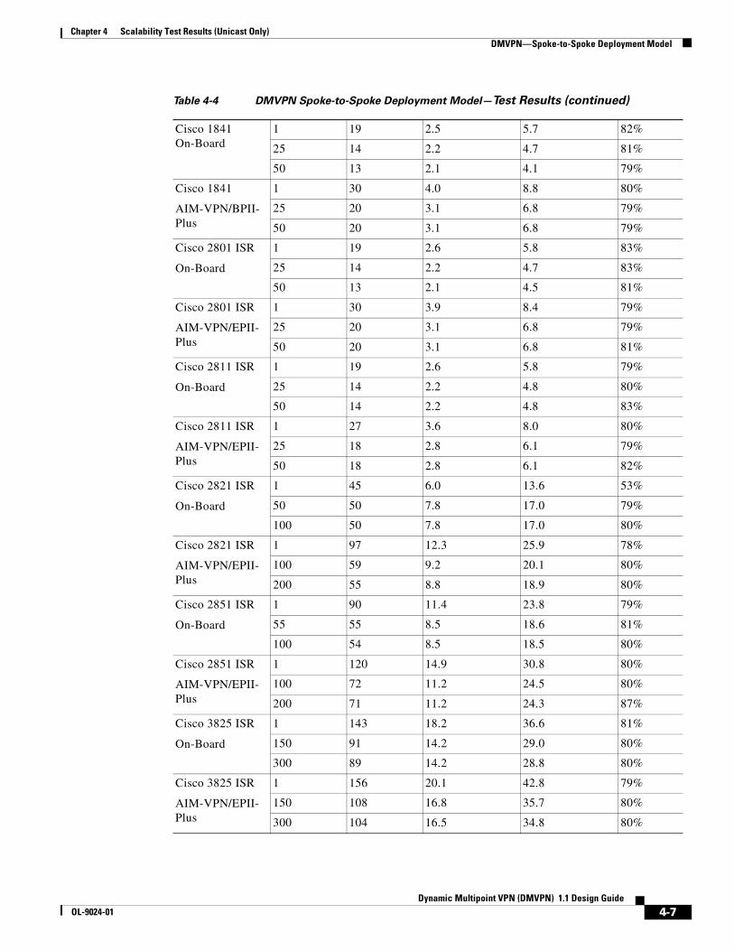
Chapter 4 Scalability Test Results (Unicast Only) DMVPN—Spoke-to-Spoke Deployment Model
Cisco 1841 On-Board
1 19 2.5 5.7 82%
25 14 2.2 4.7 81%
50 13 2.1 4.1 79%
Cisco 1841
AIM-VPN/BPII-Plus
1 30 4.0 8.8 80%
25 20 3.1 6.8 79%
50 20 3.1 6.8 79%
Cisco 2801 ISR
On-Board
1 19 2.6 5.8 83%
25 14 2.2 4.7 83%
50 13 2.1 4.5 81%
Cisco 2801 ISR
AIM-VPN/EPII-Plus
1 30 3.9 8.4 79%
25 20 3.1 6.8 79%
50 20 3.1 6.8 81%
Cisco 2811 ISR
On-Board
1 19 2.6 5.8 79%
25 14 2.2 4.8 80%
50 14 2.2 4.8 83%
Cisco 2811 ISR
AIM-VPN/EPII-Plus
1 27 3.6 8.0 80%
25 18 2.8 6.1 79%
50 18 2.8 6.1 82%
Cisco 2821 ISR
On-Board
1 45 6.0 13.6 53%
50 50 7.8 17.0 79%
100 50 7.8 17.0 80%
Cisco 2821 ISR
AIM-VPN/EPII-Plus
1 97 12.3 25.9 78%
100 59 9.2 20.1 80%
200 55 8.8 18.9 80%
Cisco 2851 ISR
On-Board
1 90 11.4 23.8 79%
55 55 8.5 18.6 81%
100 54 8.5 18.5 80%
Cisco 2851 ISR
AIM-VPN/EPII-Plus
1 120 14.9 30.8 80%
100 72 11.2 24.5 80%
200 71 11.2 24.3 87%
Cisco 3825 ISR
On-Board
1 143 18.2 36.6 81%
150 91 14.2 29.0 80%
300 89 14.2 28.8 80%
Cisco 3825 ISR
AIM-VPN/EPII-Plus
1 156 20.1 42.8 79%
150 108 16.8 35.7 80%
300 104 16.5 34.8 80%
Table 4-4 DMVPN Spoke-to-Spoke Deployment Model—Test Results (continued)
4-7Dynamic Multipoint VPN (DMVPN) 1.1 Design Guide
OL-9024-01

Chapter 4 Scalability Test Results (Unicast Only) DMVPN—Spoke-to-Spoke Deployment Model
AES versus 3DES Scalability Test ResultsBoth 3DES and AES encryption are available in all products shown here, including hardware-accelerated IPsec. Not every test was executed with both 3DES and AES; however, several snapshot tests were performed to compare performance. As can be seen in the chart in Figure 4-3, results are fairly comparable, with little to no variation in performance, even for AES with wider key lengths.
Cisco 3845 ISR
On-Board
1 187 24.0 48.8 81%
200 118 18.4 37.7 80%
400 114 18.1 36.7 80%
Cisco 3845 ISR
AIM-VPN/HPII-Plus
1 420 27.1 58.1 80%
200 280 21.7 46.3 80%
400 270 21.4 45.2 80%
Cisco 7200VXR
NPE-G1
Dual SA-VAM2
1 480 30.4 63.1 79%
200 340 26.4 56.2 79%
400 320 25.2 53.3 80%
Cisco 7301
SA-VAM2
1 240 31.0 66.1 80%
200 160 24.7 50.1 79%
400 150 23.6 47.6 79%
Table 4-4 DMVPN Spoke-to-Spoke Deployment Model—Test Results (continued)
4-8Dynamic Multipoint VPN (DMVPN) 1.1 Design Guide
OL-9024-01

Chapter 4 Scalability Test Results (Unicast Only) Software Releases Evaluated
Figure 4-3 Comparison of 3DES and AES Performance
Software Releases EvaluatedThe software releases shown in Table 4-5 were used in the scalability testing:
1481
87
0
5,000
10,000
15,000
20,000
25,000
30,000
35,000
pps3DESAES128AES192AES256
Cisco 3845 On-Board Cisco 3845AIM-VPN/HPII-PLUS
Cisco 7200VXR-NPE-G1SA-VAM2+
Table 4-5 Software Releases Evaluated
Cisco Product Family SW Release
Cisco ASR 1000 12.2(33)XNA
Cisco 7600 IOS 12.2(18)SXE2
Cisco 6500 VPNSM IOS 12.2(18)SXE2
Cisco 7200VXR IOS 12.2(11)T2
IOS 12.3(5)
Cisco 7200VXR NPE-G2 with VPN Services Adapter
IOS 124-4.XD-0629
Cisco branch office routers (17xx, 26xx, 36xx, 37xx)
IOS 12.3(8)T5
4-9Dynamic Multipoint VPN (DMVPN) 1.1 Design Guide
OL-9024-01

Chapter 4 Scalability Test Results (Unicast Only) Software Releases Evaluated
As always, before selecting Cisco IOS software, perform the appropriate research. It is also important to have an understanding of issues in those levels of code that may affect other features configured on routers.
Cisco branch office ISRs
(1841, 28xx, 38xx)
IOS 12.3(8)T5
IOS 12.3(11)T2
Cisco remote office routers (831, 871W, and 1811W)
831—IOS 12.3(8)T5 871W—IOS 12.3(8)Y1 1811W—IOS 12.3(14)YT1
Table 4-5 Software Releases Evaluated
4-10Dynamic Multipoint VPN (DMVPN) 1.1 Design Guide
OL-9024-01

DynamicOL-9024-01
A
P P E N D I X A Scalability Test Bed Configuration FilesThe configurations for the central and branch sites are listed below in the following sections. These configurations have been extracted from real configurations used in Cisco scalability testing, and are provided as a reference only.
Cisco 7200VXR/NPE-G1/SA-VAM2 Headend ConfigurationThere are two headend devices in the test bed, each configured with one mGRE tunnel. A dual hub-dual DMVPN cloud design is assumed. The configuration shown below is an excerpt of the first headend and does not show the entire configuration. Pre-shared keys with a wildcard address are used at the headend for simplicity of the ISAKMP authentication, although this is not recommended for customer use.
Headend #1:
ip cef!crypto isakmp policy 1 encr 3des authentication pre-share group 2crypto isakmp key bigsecret address 0.0.0.0 0.0.0.0!crypto ipsec transform-set vpn-test esp-3des esp-sha-hmac no crypto ipsec nat-transparency udp-encaps!crypto ipsec profile vpn-dmvpn set transform-set vpn-test !interface Loopback0 description Loopback0 ip address 10.57.1.255 255.255.255.255!interface Tunnel0 description Tunnel0 bandwidth 1000000 ip address 10.56.0.1 255.255.252.0 no ip redirects ip hold-time eigrp 1 35 ip nhrp authentication test ip nhrp map multicast dynamic ip nhrp network-id 105600 ip nhrp holdtime 600 no ip split-horizon eigrp 1 ip summary-address eigrp 1 10.0.0.0 255.0.0.0 5 tunnel source GigabitEthernet0/1
A-1 Multipoint VPN (DMVPN) 1.1 Design Guide

Appendix A Scalability Test Bed Configuration Files Cisco ASR1004 Headend Configuration
tunnel mode gre multipoint tunnel key 105600 tunnel protection ipsec profile vpn-dmvpn! interface GigabitEthernet0/1 description GigabitEthernet0/1 ip address 192.168.251.1 255.255.255.248 duplex auto speed auto media-type gbic negotiation auto!interface GigabitEthernet0/2 description GigabitEthernet0/2 ip address 10.57.1.1 255.255.255.248 duplex auto speed auto media-type gbic negotiation auto!router eigrp 1 network 10.0.0.0 no auto-summary!ip route 192.168.0.0 255.255.0.0 192.168.251.2!
Cisco ASR1004 Headend ConfigurationThis configuration is for the Cisco ASR1004, where the ASR is aggregating 1000 DMVPN hub-and-spoke tunnels.
Headend #1:
boot-start-markerboot system flash bootflash:asr1000rp1-adventerprisek9.02.01.00.122-33.XNA.binboot-end-marker!vrf definition Mgmt-intf ! address-family ipv4 exit-address-family ! address-family ipv6 exit-address-family!logging buffered 1024000enable password cisco!no aaa new-modelclock timezone EST -5clock summer-time EDT recurringip subnet-zerono ip ftp passiveip ftp source-interface GigabitEthernet0ip tftp source-interface GigabitEthernet0no ip domain lookup!!!
A-2Dynamic Multipoint VPN (DMVPN) 1.1 Design Guide
OL-9024-01

Appendix A Scalability Test Bed Configuration Files Cisco ASR1004 Headend Configuration
!!multilink bundle-name authenticated!!!redundancy mode sso no policy config-sync bulk prc reload!!! !crypto isakmp policy 10 encr aes 256 authentication pre-share group 2crypto isakmp key bigsecret address 0.0.0.0 0.0.0.0crypto isakmp keepalive 10!!crypto ipsec transform-set vpn-test esp-aes esp-sha-hmac !crypto ipsec profile vpn-dmvpn set transform-set vpn-test !!!buffers tune automatic!!!interface Tunnel0 description Tunnel0 bandwidth 100000 ip address 10.56.0.1 255.255.248.0 no ip redirects ip hold-time eigrp 1 35 no ip next-hop-self eigrp 1 ip nhrp authentication test ip nhrp map multicast dynamic ip nhrp network-id 105600 ip nhrp holdtime 1800 ip nhrp registration timeout 120 no ip split-horizon eigrp 1 load-interval 30 qos pre-classify tunnel source Loopback0 tunnel mode gre multipoint tunnel key 105600 tunnel protection ipsec profile vpn-dmvpn!interface Loopback0 ip address 192.168.30.1 255.255.255.255!interface GigabitEthernet0/2/0 description GigabitEthernet0/2/0 ip address 192.168.32.252 255.255.255.0 no ip proxy-arp load-interval 30 negotiation auto plim qos input map ip dscp-based plim qos input map ip dscp 34 40 queue strict-priority no cdp enable
A-3Dynamic Multipoint VPN (DMVPN) 1.1 Design Guide
OL-9024-01

Appendix A Scalability Test Bed Configuration Files Cisco 7600/Sup720/VPN SPA Headend Configuration
hold-queue 4096 in hold-queue 4096 out!!interface GigabitEthernet0/3/0 description GigabitEthernet0/3/0 ip address 10.204.0.1 255.252.0.0 load-interval 30 negotiation auto plim qos input map ip dscp-based plim qos input map ip dscp 34 40 queue strict-priority no cdp enable service-policy input INGRESS service-policy output campus!!interface GigabitEthernet0 vrf forwarding Mgmt-intf ip address 172.26.182.168 255.255.252.0 speed 100 duplex full no negotiation auto!router eigrp 1 network 10.0.0.0 no auto-summary passive-interface GigabitEthernet0/2/2!router eigrp 100 network 192.168.32.0!ip classlessip route vrf Mgmt-intf 0.0.0.0 0.0.0.0 172.26.180.1!no ip http serverno ip http secure-server!!snmp-server community public ROsnmp-server community private RW!!!control-plane!!line con 0 stopbits 1line vty 0 4 exec-timeout 0 0 password cisco login!ntp clock-period 17175902end
Cisco 7600/Sup720/VPN SPA Headend ConfigurationThis configuration is for the Cisco 7600 with Sup720 and VPN SPA where the 7600 router is aggregating 1000 DMVPN hub-and-spoke tunnels.
A-4Dynamic Multipoint VPN (DMVPN) 1.1 Design Guide
OL-9024-01
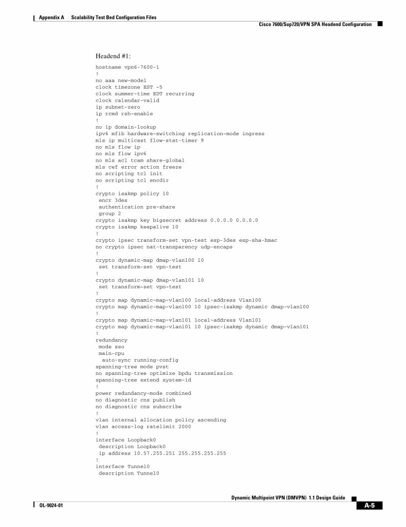
Appendix A Scalability Test Bed Configuration Files Cisco 7600/Sup720/VPN SPA Headend Configuration
Headend #1:
hostname vpn6-7600-1!no aaa new-modelclock timezone EST -5clock summer-time EDT recurringclock calendar-validip subnet-zeroip rcmd rsh-enable!no ip domain-lookupipv6 mfib hardware-switching replication-mode ingressmls ip multicast flow-stat-timer 9no mls flow ipno mls flow ipv6no mls acl tcam share-globalmls cef error action freezeno scripting tcl initno scripting tcl encdir!crypto isakmp policy 10 encr 3des authentication pre-share group 2crypto isakmp key bigsecret address 0.0.0.0 0.0.0.0crypto isakmp keepalive 10!crypto ipsec transform-set vpn-test esp-3des esp-sha-hmac no crypto ipsec nat-transparency udp-encaps!crypto dynamic-map dmap-vlan100 10 set transform-set vpn-test !crypto dynamic-map dmap-vlan101 10 set transform-set vpn-test !crypto map dynamic-map-vlan100 local-address Vlan100crypto map dynamic-map-vlan100 10 ipsec-isakmp dynamic dmap-vlan100 !crypto map dynamic-map-vlan101 local-address Vlan101crypto map dynamic-map-vlan101 10 ipsec-isakmp dynamic dmap-vlan101 !redundancy mode sso main-cpu auto-sync running-configspanning-tree mode pvstno spanning-tree optimize bpdu transmissionspanning-tree extend system-id!power redundancy-mode combinedno diagnostic cns publishno diagnostic cns subscribe!vlan internal allocation policy ascendingvlan access-log ratelimit 2000!interface Loopback0 description Loopback0 ip address 10.57.255.251 255.255.255.255!interface Tunnel0 description Tunnel0
A-5Dynamic Multipoint VPN (DMVPN) 1.1 Design Guide
OL-9024-01
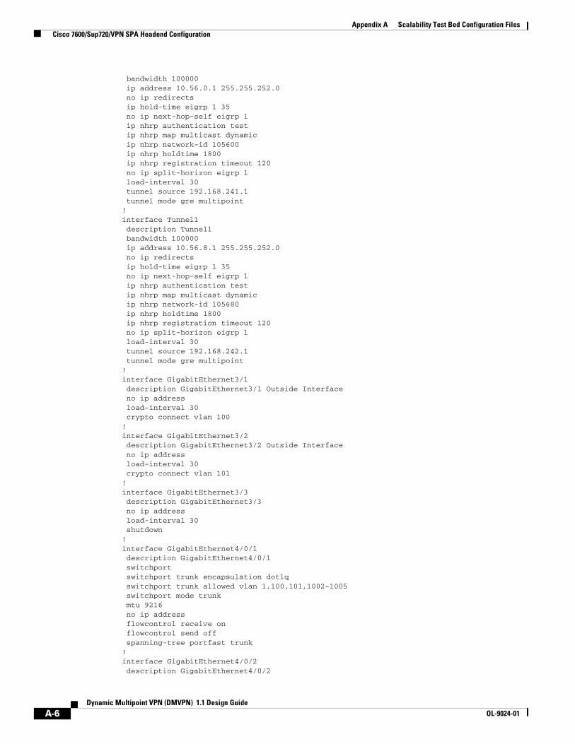
Appendix A Scalability Test Bed Configuration Files Cisco 7600/Sup720/VPN SPA Headend Configuration
bandwidth 100000 ip address 10.56.0.1 255.255.252.0 no ip redirects ip hold-time eigrp 1 35 no ip next-hop-self eigrp 1 ip nhrp authentication test ip nhrp map multicast dynamic ip nhrp network-id 105600 ip nhrp holdtime 1800 ip nhrp registration timeout 120 no ip split-horizon eigrp 1 load-interval 30 tunnel source 192.168.241.1 tunnel mode gre multipoint!interface Tunnel1 description Tunnel1 bandwidth 100000 ip address 10.56.8.1 255.255.252.0 no ip redirects ip hold-time eigrp 1 35 no ip next-hop-self eigrp 1 ip nhrp authentication test ip nhrp map multicast dynamic ip nhrp network-id 105680 ip nhrp holdtime 1800 ip nhrp registration timeout 120 no ip split-horizon eigrp 1 load-interval 30 tunnel source 192.168.242.1 tunnel mode gre multipoint!interface GigabitEthernet3/1 description GigabitEthernet3/1 Outside Interface no ip address load-interval 30 crypto connect vlan 100!interface GigabitEthernet3/2 description GigabitEthernet3/2 Outside Interface no ip address load-interval 30 crypto connect vlan 101!interface GigabitEthernet3/3 description GigabitEthernet3/3 no ip address load-interval 30 shutdown!interface GigabitEthernet4/0/1 description GigabitEthernet4/0/1 switchport switchport trunk encapsulation dot1q switchport trunk allowed vlan 1,100,101,1002-1005 switchport mode trunk mtu 9216 no ip address flowcontrol receive on flowcontrol send off spanning-tree portfast trunk!interface GigabitEthernet4/0/2 description GigabitEthernet4/0/2
A-6Dynamic Multipoint VPN (DMVPN) 1.1 Design Guide
OL-9024-01

Appendix A Scalability Test Bed Configuration Files Cisco 7600/Sup720/VPN SPA Headend Configuration
switchport switchport trunk encapsulation dot1q switchport trunk allowed vlan 1,1002-1005 switchport mode trunk mtu 9216 no ip address flowcontrol receive on flowcontrol send off spanning-tree portfast trunk!interface GigabitEthernet5/1 description GigabitEthernet5/1 Inside Interface ip address 10.57.1.1 255.255.255.0 no ip redirects load-interval 30!interface GigabitEthernet6/2 description FlashNet ip address 172.26.177.251 255.255.252.0 load-interval 30 media-type rj45 speed 100 duplex full!interface Vlan1 description Vlan1 no ip address load-interval 30 shutdown!interface Vlan100 description Vlan100 ip address 192.168.241.1 255.255.255.0 no ip redirects load-interval 30 no mop enabled crypto map dynamic-map-vlan100 crypto engine subslot 4/0!interface Vlan101 description Vlan101 ip address 192.168.242.1 255.255.255.0 no ip redirects load-interval 30 no mop enabled crypto map dynamic-map-vlan101 crypto engine subslot 4/0!router eigrp 1 network 10.0.0.0 no auto-summary!ip classlessip route 0.0.0.0 0.0.0.0 172.26.176.1ip route 10.60.0.254 255.255.255.255 192.168.241.2ip route 10.60.1.254 255.255.255.255 192.168.241.2ip route 10.60.2.254 255.255.255.255 192.168.241.2ip route 10.60.3.254 255.255.255.255 192.168.241.2ip route 10.60.4.254 255.255.255.255 192.168.241.2ip route 10.60.5.254 255.255.255.255 192.168.241.2ip route 10.60.6.254 255.255.255.255 192.168.241.2ip route 10.60.7.254 255.255.255.255 192.168.241.2ip route 10.60.8.254 255.255.255.255 192.168.241.2ip route 10.60.9.254 255.255.255.255 192.168.241.2
A-7Dynamic Multipoint VPN (DMVPN) 1.1 Design Guide
OL-9024-01

Appendix A Scalability Test Bed Configuration Files Cisco 7200VXR/Cisco 7600 Dual Tier Architecture Headend Configuration
ip route 10.60.10.254 255.255.255.255 192.168.241.2. . . lines omitted . . .ip route 10.67.0.254 255.255.255.255 192.168.242.2ip route 10.67.1.254 255.255.255.255 192.168.242.2ip route 10.67.2.254 255.255.255.255 192.168.242.2ip route 10.67.3.254 255.255.255.255 192.168.242.2ip route 10.67.4.254 255.255.255.255 192.168.242.2ip route 10.67.5.254 255.255.255.255 192.168.242.2ip route 10.67.6.254 255.255.255.255 192.168.242.2ip route 10.67.7.254 255.255.255.255 192.168.242.2ip route 10.67.8.254 255.255.255.255 192.168.242.2ip route 10.67.9.254 255.255.255.255 192.168.242.2ip route 10.67.10.254 255.255.255.255 192.168.242.2ip route 10.67.11.254 255.255.255.255 192.168.242.2ip route 10.67.12.254 255.255.255.255 192.168.242.2ip route 10.67.13.254 255.255.255.255 192.168.242.2ip route 10.67.14.254 255.255.255.255 192.168.242.2ip route 10.67.15.254 255.255.255.255 192.168.242.2ip route 10.67.16.254 255.255.255.255 192.168.242.2ip route 10.67.17.254 255.255.255.255 192.168.242.2ip route 10.67.18.254 255.255.255.255 192.168.242.2ip route 10.67.19.254 255.255.255.255 192.168.242.2ip route 172.26.0.0 255.255.0.0 172.26.176.1ip route 192.168.0.0 255.255.0.0 192.168.241.2ip route 192.168.0.0 255.255.0.0 192.168.242.2!no ip http server!snmp-server community public ROsnmp-server community private RWsnmp-server system-shutdown!control-plane!dial-peer cor custom!line con 0 exec-timeout 0 0 password cisco loginline vty 0 4 exec-timeout 0 0 password cisco login!ntp clock-period 17180019ntp server 172.26.176.1no cns aaa enableend
Cisco 7200VXR/Cisco 7600 Dual Tier Architecture Headend Configuration
This configuration is for the Cisco 7200VXR terminating mGRE and the Cisco 7600 with Sup720 and VPN SPA providing high-capacity IPsec encryption.
A-8Dynamic Multipoint VPN (DMVPN) 1.1 Design Guide
OL-9024-01

Appendix A Scalability Test Bed Configuration Files Cisco 7200VXR/Cisco 7600 Dual Tier Architecture Headend Configuration
Tier #1 (mGRE)hostname vpn2-7200-1!clock timezone EST -5clock summer-time EDT recurringclock calendar-validno aaa new-modelip subnet-zeroip rcmd rsh-enable!ip cefno ip domain lookup!ip multicast-routing ip ips po max-events 100no ftp-server write-enable!interface Tunnel0 description Tunnel0 bandwidth 100000 ip address 10.56.0.1 255.255.252.0 no ip redirects ip hold-time eigrp 1 35 no ip next-hop-self eigrp 1 ip pim nbma-mode ip pim sparse-mode ip nhrp authentication test ip nhrp map multicast dynamic ip nhrp network-id 105600 ip nhrp holdtime 1800 ip nhrp registration timeout 120 no ip split-horizon eigrp 1 load-interval 30 tunnel source 192.168.161.1 tunnel mode gre multipoint tunnel key 105600!interface Tunnel1 description Tunnel1 bandwidth 100000 ip address 10.56.16.1 255.255.252.0 no ip redirects ip hold-time eigrp 1 35 no ip next-hop-self eigrp 1 ip pim nbma-mode ip pim sparse-mode ip nhrp authentication test ip nhrp map multicast dynamic ip nhrp network-id 1056160 ip nhrp holdtime 1800 ip nhrp registration timeout 120 no ip split-horizon eigrp 1 load-interval 30 tunnel source 192.168.181.1 tunnel mode gre multipoint tunnel key 1056160!interface Loopback0 description Loopback0 ip address 10.57.255.251 255.255.255.255!interface FastEthernet0/0
A-9Dynamic Multipoint VPN (DMVPN) 1.1 Design Guide
OL-9024-01

Appendix A Scalability Test Bed Configuration Files Cisco 7200VXR/Cisco 7600 Dual Tier Architecture Headend Configuration
description FlashNet ip address 172.26.176.14 255.255.252.0 load-interval 30 duplex full speed 100!interface FastEthernet0/1 description FastEthernet0/1 no ip address load-interval 30 shutdown duplex full speed 100!interface GigabitEthernet0/1 description GigabitEthernet0/1 ip address 192.168.181.1 255.255.255.0 secondary ip address 192.168.161.1 255.255.255.0 load-interval 30 duplex auto speed auto media-type gbic negotiation auto!interface GigabitEthernet0/2 description GigabitEthernet0/2 ip address 10.57.1.1 255.255.255.0 ip pim sparse-mode load-interval 30 duplex auto speed auto media-type gbic negotiation auto!interface GigabitEthernet0/3 description GigabitEthernet0/3 no ip address load-interval 30 shutdown duplex auto speed auto media-type gbic negotiation auto!router eigrp 1 network 10.0.0.0 no auto-summary!ip classlessip route 0.0.0.0 0.0.0.0 172.26.176.1ip route 172.26.0.0 255.255.0.0 172.26.176.1ip route 192.168.0.0 255.255.0.0 192.168.161.2ip route 192.168.0.0 255.255.0.0 192.168.181.2!ip http serverno ip http secure-server!ip pim autorp listener!snmp-server community public ROsnmp-server community private RWsnmp-server system-shutdownsnmp-server enable traps tty!
A-10Dynamic Multipoint VPN (DMVPN) 1.1 Design Guide
OL-9024-01

Appendix A Scalability Test Bed Configuration Files Cisco 7200VXR/Cisco 7600 Dual Tier Architecture Headend Configuration
control-plane!dial-peer cor custom!gatekeeper shutdown!line con 0 exec-timeout 0 0 password cisco login transport preferred all transport output all stopbits 1line aux 0 transport preferred all transport output all stopbits 1line vty 0 4 exec-timeout 0 0 password cisco login transport preferred all transport input all transport output allline vty 5 15 exec-timeout 0 0 password cisco login transport preferred all transport input all transport output all!ntp clock-period 17180034ntp server 172.26.176.1!end
Tier #2 (IPsec)hostname vpn6-7600-1!no aaa new-modelclock timezone EST -5clock summer-time EDT recurringclock calendar-validip subnet-zeroip rcmd rsh-enable!no ip domain-lookupipv6 mfib hardware-switching replication-mode ingressmls ip multicast flow-stat-timer 9no mls flow ipno mls flow ipv6no mls acl tcam share-globalmls cef error action freezeno scripting tcl initno scripting tcl encdir!crypto isakmp policy 10 encr 3des
A-11Dynamic Multipoint VPN (DMVPN) 1.1 Design Guide
OL-9024-01
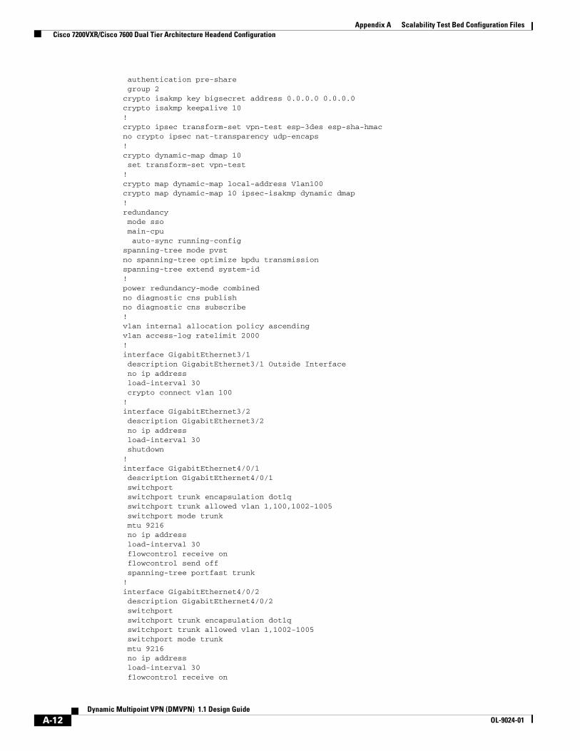
Appendix A Scalability Test Bed Configuration Files Cisco 7200VXR/Cisco 7600 Dual Tier Architecture Headend Configuration
authentication pre-share group 2crypto isakmp key bigsecret address 0.0.0.0 0.0.0.0crypto isakmp keepalive 10!crypto ipsec transform-set vpn-test esp-3des esp-sha-hmac no crypto ipsec nat-transparency udp-encaps!crypto dynamic-map dmap 10 set transform-set vpn-test !crypto map dynamic-map local-address Vlan100crypto map dynamic-map 10 ipsec-isakmp dynamic dmap !redundancy mode sso main-cpu auto-sync running-configspanning-tree mode pvstno spanning-tree optimize bpdu transmissionspanning-tree extend system-id!power redundancy-mode combinedno diagnostic cns publishno diagnostic cns subscribe!vlan internal allocation policy ascendingvlan access-log ratelimit 2000!interface GigabitEthernet3/1 description GigabitEthernet3/1 Outside Interface no ip address load-interval 30 crypto connect vlan 100!interface GigabitEthernet3/2 description GigabitEthernet3/2 no ip address load-interval 30 shutdown!interface GigabitEthernet4/0/1 description GigabitEthernet4/0/1 switchport switchport trunk encapsulation dot1q switchport trunk allowed vlan 1,100,1002-1005 switchport mode trunk mtu 9216 no ip address load-interval 30 flowcontrol receive on flowcontrol send off spanning-tree portfast trunk!interface GigabitEthernet4/0/2 description GigabitEthernet4/0/2 switchport switchport trunk encapsulation dot1q switchport trunk allowed vlan 1,1002-1005 switchport mode trunk mtu 9216 no ip address load-interval 30 flowcontrol receive on
A-12Dynamic Multipoint VPN (DMVPN) 1.1 Design Guide
OL-9024-01

Appendix A Scalability Test Bed Configuration Files Cisco 7200VXR/Cisco 7600 Dual Tier Architecture Headend Configuration
flowcontrol send off spanning-tree portfast trunk!interface GigabitEthernet5/1 description GigabitEthernet5/1 to vpn2-7200-1 GE0/1 ip address 192.168.181.2 255.255.255.0 secondary ip address 192.168.161.2 255.255.255.0 no ip redirects load-interval 30!interface GigabitEthernet5/2 description GigabitEthernet5/2 to vpn2-7200-2 GE0/1 ip address 192.168.191.2 255.255.255.0 secondary ip address 192.168.171.2 255.255.255.0 no ip redirects load-interval 30!interface GigabitEthernet5/3 description GigabitEthernet5/3 no ip address load-interval 30 shutdown!interface GigabitEthernet6/2 description FlashNet ip address 172.26.177.251 255.255.252.0 load-interval 30 media-type rj45 speed 100 duplex full!interface Vlan1 description Vlan1 no ip address load-interval 30 shutdown!interface Vlan100 description Vlan100 ip address 192.168.241.1 255.255.255.0 load-interval 30 no mop enabled crypto map dynamic-map crypto engine subslot 4/0!ip classlessip route 0.0.0.0 0.0.0.0 172.26.176.1ip route 172.26.0.0 255.255.0.0 172.26.176.1ip route 192.168.0.0 255.255.0.0 192.168.241.2!no ip http server!snmp-server community public ROsnmp-server community private RWsnmp-server system-shutdown!control-plane!dial-peer cor custom!line con 0 exec-timeout 0 0 password cisco login
A-13Dynamic Multipoint VPN (DMVPN) 1.1 Design Guide
OL-9024-01

Appendix A Scalability Test Bed Configuration Files Cisco ISR Branch Office Configuration
line vty 0 4 exec-timeout 0 0 password cisco login!ntp clock-period 17180035ntp server 172.26.176.1no cns aaa enableend
Cisco ISR Branch Office ConfigurationThe following shows relevant configurations for one branch site router. A dual hub-dual DMVPN cloud design is employed by using two tunnels, one to each headend. The EIGRP delay metric is used to make Tunnel0 the preferred path. This configuration shows QoS for VoIP flows (shaping and queuing) applied to the physical (outside) interface, the recommended use of summary routes, and an EIGRP stub configuration.
Branch #1:
ip cef!crypto isakmp policy 1 encr 3des authentication pre-share group 2crypto isakmp key bigsecret address 192.168.251.1crypto isakmp key bigsecret address 192.168.252.1!crypto ipsec transform-set vpn-test esp-3des esp-sha-hmac no crypto ipsec nat-transparency udp-encaps!crypto ipsec profile vpn-dmvpn set transform-set vpn-test !class-map match-all VOICE match ip dscp ef class-map match-any CALL-SETUP match ip dscp af31 match ip dscp cs3 class-map match-any INTERNETWORK-CONTROL match ip dscp cs6 match access-group name IKE class-map match-all TRANSACTIONAL-DATA match ip dscp af21 ! policy-map 192kb class CALL-SETUP bandwidth percent 2 class INTERNETWORK-CONTROL bandwidth percent 5 class TRANSACTIONAL-DATA bandwidth percent 22 queue-limit 16 class VOICE priority 64 class class-default fair-queue queue-limit 6 policy-map 192kb-shaper
A-14Dynamic Multipoint VPN (DMVPN) 1.1 Design Guide
OL-9024-01

Appendix A Scalability Test Bed Configuration Files Cisco ISR Branch Office Configuration
class class-default shape average 182400 1824 0 service-policy 192kb!interface Loopback0 description Loopback0 ip address 10.61.138.254 255.255.255.255!interface Tunnel0 description Tunnel0 bandwidth 192 ip address 10.56.3.10 255.255.252.0 ip hold-time eigrp 1 35 ip nhrp authentication test ip nhrp map 10.56.0.1 192.168.251.1 ip nhrp map multicast 192.168.251.1 ip nhrp network-id 105600 ip nhrp holdtime 300 ip nhrp nhs 10.56.0.1 ip summary-address eigrp 1 10.61.148.0 255.255.255.0 5 qos pre-classify tunnel source 192.168.100.6 tunnel destination 192.168.251.1 tunnel key 105600 tunnel protection ipsec profile vpn-dmvpn!interface Tunnel1 description Tunnel1 bandwidth 192 ip address 10.56.7.10 255.255.252.0 ip hold-time eigrp 1 35 ip nhrp authentication test ip nhrp map 10.56.4.1 192.168.252.1 ip nhrp map multicast 192.168.252.1 ip nhrp network-id 105640 ip nhrp holdtime 300 ip nhrp nhs 10.56.4.1 ip summary-address eigrp 1 10.61.148.0 255.255.255.0 5 delay 60000 qos pre-classify tunnel source 192.168.100.6 tunnel destination 192.168.252.1 tunnel key 105640 tunnel protection ipsec profile vpn-dmvpn!interface Serial0/0 description Serial0/0 bandwidth 192 ip address 192.168.100.6 255.255.255.252 service-policy output 192kb-shaper!interface FastEthernet0/1 description FastEthernet0/1 ip address 10.61.148.129 255.255.255.192 secondary ip address 10.61.148.1 255.255.255.128 speed 100 full-duplex!router eigrp 1 network 10.0.0.0 no auto-summary eigrp stub connected summary!ip route 0.0.0.0 0.0.0.0 192.168.100.5!
A-15Dynamic Multipoint VPN (DMVPN) 1.1 Design Guide
OL-9024-01

Appendix A Scalability Test Bed Configuration Files Cisco ISR Branch Office Configuration
ip access-list extended IKE permit udp any any eq isakmp!
A-16Dynamic Multipoint VPN (DMVPN) 1.1 Design Guide
OL-9024-01

DynamicOL-9024-01
A
P P E N D I X B Legacy Product Test ResultsThis chapter contains scalability test results for legacy products.
The encryption strength used is 3DES, and the Cisco IOS version is 12.3(8)T5 for all spoke devices (unless otherwise noted), with 12.3(8)T4 on the NHRP-serving hub router. Each device is profiled at three or four levels of CPU (equating roughly to 50 percent, 60 percent, and so forth) to determine its performance curve. All devices are tested with hardware encryption modules, Cisco IOS-FW, and NAT enabled, as shown in Table B-1.
Table B-1 Scalability Test Results for Legacy Products
Platform # Tunnels Throughput (Kpps) Throughput (Mbps) CPU %
Cisco 831
On-Board
1 .48 1.1 75%
5 .47 1.0 74%
10 .47 1.0 75%
Cisco 1711
On-Board
1 .9 2.1 81%
12 .8 1.7 82%
25 .8 1.7 84%
Cisco 1760
MOD1700-VPN
1 1.0 2.0 81%
12 .9 1.8 83%
25 .9 1.8 85%
Cisco 2651XM
AIM-VPN/BPII
1 1.3 3.0 85%
12 1.1 2.4 78%
25 1.1 2.4 79%
Cisco 2691
AIM-VPN/EPII
1 5.1 11.4 82%
50 4.5 9.9 82%
100 4.4 9.7 81%
Cisco 3725
AIM-VPN/BPII
1 6.9 15.5 81%
62 6.1 13.3 80%
125 5.9 12.8 80%
Cisco 3745
AIM-VPN/HPII
1 13.4 28.8 82%
100 11.6 25.4 79%
200 11.2 24.1 81%
B-1 Multipoint VPN (DMVPN) 1.1 Design Guide

DynamicOL-9024-01
A
P P E N D I X C AcronymsTable 1:
Term Definition
3DES Triple Data Encryption Standard
ACL Access control list
AES Advanced Encryption Standard
AH Authentication Header
AIM Advanced Integration Module
ATM Asynchronous Transfer Mode
CA Certificate Authority
CAC Call Admission Control
CBWFQ Class-Based Weighted Fair Queuing
CEF Cisco Express Forwarding
CPE Customer Premises Equipment
cRTP Compressed Real-Time Protocol
DES Data Encryption Standard
DHCP Dynamic Host Configuration Protocol
DLSw Data Link Switching
DMVPN Dynamic Multipoint Virtual Private Network
DMZ De-Militarized Zone
DNS Domain Name Service
DPD Dead Peer Detection
DSL Digital Subscriber Line
EIGRP Enhanced Interior Gateway Routing Protocol
ESP Encapsulating Security Protocol
FIFO First In First Out
FQDN Fully Qualified Domain Name
FR Frame Relay
FRTS Frame Relay Traffic Shaping
C-1 Multipoint VPN (DMVPN) 1.1 Design Guide

Appendix C Acronyms
FTP File Transfer Protocol
GRE Generic Route Encapsulation
HSRP Hot Standby Router Protocol
ICMP Internet Control Message Protocol
IKE Internet Key Exchange
IOS Internetwork Operating System
IP Internet Protocol
IPmc IP Multicast
IPSec IP Security
IP GRE See GRE
ISP Internet Service Provider
LFI Link Fragmentation and Interleaving
LLQ Low Latency Queuing
L2TP Layer 2 Tunneling Protocol
MDRR Modified Deficit Round Robin
mGRE Multipoint Generic Route Encapsulation
MLPPP Multi-link Point to Point Protocol
MPLS Multi-Protocol Label Switching
MTU Maximum Transmission Unit
NAT Network Address Translation
NetFlow Cisco IOS component, collects and exports traffic statistics
NHRP Next Hop Resolution Protocol
NHS Next-Hop Server
ODR On-Demand Routing
OSPF Open Shortest Path First
p2p GRE Point-to-Point GRE
PAT Port Address Translation
PBR Policy-Based Routing
PE Premises Equipment
PPTP Point-to-Point Tunneling Protocol
PVC Permanent Virtual Circuit
QoS Quality of Service
RADIUS Remote Authentication Dial In User System
RTP Real-Time Protocol
SA Security Association
SAA Service Assurance Agent
SHA-1 Secure Hash Algorithm One
Table 1:
C-2Dynamic Multipoint VPN (DMVPN) 1.1 Design Guide
OL-9024-01

Appendix C Acronyms
SLA Service Level Agreement
SNMP Simple Network Management Protocol
SOHO Small Office/Home Office
SPA Shared Port Adapter
SRST Survivable Remote Site Telephony
TCP Transmission Control Protocol
TED Tunnel Endpoint Discovery
ToS Type of Service
UDP User Datagram Protocol
VAD Voice Activity Detection
VoIP Voice over IP
V3PN Voice and Video Enabled IPSec VPN
VAM VPN Acceleration Module
VPN Virtual Private Network
VPNSM VPN Service Module
VPN SPA VPN Shared Port Adapter
WAN Wide Area Network
WRED Weighted Random Early Detection
Table 1:
C-3Dynamic Multipoint VPN (DMVPN) 1.1 Design Guide
OL-9024-01
Related Documents


![community.cisco.com · Web view1 - Cisco Systems - # RELEASE Model=8831 Version=sip8831.10-3-1SR2-2 [ ] Sat Jan 1 00:00:06 2000 [1] 0000 INF 00:00:06.700894 syslogd started: Cisco](https://static.cupdf.com/doc/110x72/5c97c78509d3f2bd028cad26/-web-view1-cisco-systems-release-model8831-versionsip883110-3-1sr2-2.jpg)