-I.- , -i I U I U.S. DEPARTMENT OF EN 0 C R W YUCCA M m M YUCCA MOUNTAIN - SITE CHARACTERIZATION ~-- PROJECT M DRILLING AND TESTING USW WT-24 REVISION 0 A FIELD WORK PACKAGE FWP-SB-97=005 I _ _ _ _ _ _ _ _ _ _ _ _ _ _ _ _ _ _ _ _ _ _ _ _ _ _ _ JU 2 2 MT u E!.0 BY DRC UNITED STATES DEPARTMENT OF ENERGY - U_______________________ 9803050114 970721 PDR WASTE WM-li PDR ', tech SUBA T ?W,3650f/( O/7072/

Welcome message from author
This document is posted to help you gain knowledge. Please leave a comment to let me know what you think about it! Share it to your friends and learn new things together.
Transcript

-I.-
, -i �I �UI
U.S. DEPARTMENT OF EN
0CRW YUCCA
M m
��M
YUCCA MOUNTAIN- SITE CHARACTERIZATION
~-- PROJECT��M
DRILLING AND TESTING USWWT-24
REVISION 0 A
FIELD WORK PACKAGEFWP-SB-97=005
I _ _ _ _ _ _ _ _ _ _ _ _ _ _ _ _ _ _ _ _ _ _ _ _ _ _ _
JU 2 2 MT u E!.0
BY DRCUNITED STATES DEPARTMENT OF ENERGY
- U_______________________9803050114 970721PDR WASTEWM-li PDR
', tech SUBA T ?W,3650f/( O/7072/
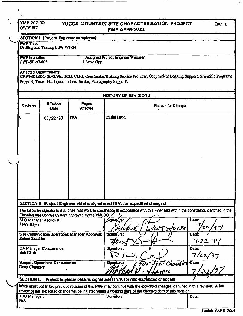
YMP-267-RO YUCCA MOUNTAIN SITE CHARACTERIZATION PROJECT OA: L05/09/97 FWP APPROVAL
SECTION I Prolect Engineer completes)FWP Title:Drilling and Testing USW Wr-24
FWP Identifier: Assigned Project Engineer/Preparer:FWP-SB-97-0os Steve Opp
Affected Organizations:CRWMS M&O (SPO/PIs, TCO, CMO, Constructor/Drilling Service Provider, Geophysical Logging Support, Scientific ProgramsSupport, Tracer Gas Injection Coordinator, Photography Support).
HISTORY OF REVISIONS
Revision Effective Pages Reason for ChangePate Affected
o 07/22/97 N/A Initial issue.
SECTION 11 (Project Engineer obtains signatures) N/A for expedited changes)The following signatures authorize field work to commence~q eccordance with this FWP and within the constraints dentified in thePlanning and Control System approved by the YMSCO. 7SPO Manager Approval: ,Signa e: Date:Larry Hayes= Rvs j ) ~~~~~~~~~~~~~~~~~t 7Site Construction/Operations Manager Approval: ure: Dat:Robert Sandifer 57-
QA Manager Concurrence: Signature: Date:Bob Clark
Support Operations Concurrence: Signature: ate:Doug Chandler
SECTION III (Project Engineer obtains signatures) (N/A for non-ex edited changes) /
Work approved In the previous revision of this FWP may continue with the expedited changes Identified In this revision. A fulreview of this expedited change will be Initiated within 3 working days of the effective date of this revision.TCO Manager: Signature: Date:N/A
Exhibit YAP-5.7Q.4
FWP-SB-97005. RO Page I of 26DRILLING & TESTING USW WT-24
INTRODUCTION .......... 3
1.0 SCOPE AND DESCRIPTION .3
1.1 General Scope Description .. 31.1.1 Planned Test Activity, Location, and Site Improvement
Description .41.1.2 Objectives .. 4
1.2 Specific Scope Description .. 51.2.1 Test Plan and Organizational Responsibilities .51.2.2 Field Testing Equipment .. 81.2.3 Computer Software .. 8
1.3 Implementing Field Documents ..................... 101.4 Data and Other Deliverables ..................... 10
1.4.1 Data Submittals .101.4.2 Test Deliverables .11
1.5 Planned Tracers, Fluids, and Material Usage and Determination ofImportance Evaluation .. 1
2.0 SAMPLING PLAN .11
2.1 Master Sample Matrix for Activity .122.2 Contingency Plans for Sampling .13
3.0 WORK IMPLEMENTATION AND CONTROL .13
3.1 Implementation......................................................................................... 133.2 Contingency Plan .193.3 Prerequisites and Hold Points .193.4 Stop Work . 19
4.0 ADMINISTRATIVE (NON-QA) INSTRUCTIONS .20
4.1 Environment, Safety, and Health .. 204.1.1 Environment .204.1.2 Safety and Health .20
4.2 Point of Contact .234.3 Schedule .23
5.0 FIELD VERIFICATION AND SCOPE COMPLETION . .235.1 Field Verifications .235.2 Scope Completion .23
;0- FWP-SB-97-00S, RO Page 2 of 26DRILLING & TESTING USW WT-24
6.0 RECORDS SUBMIlTAL ................... 24
6.1 Records Identification...............................................................................246.2 Records Generation ................... 25
7.0 ATTACHMENTS ................... 25
8.0 REFERENCES ................... 26
FWP-SB-97-005, RO Page 3 of 26DRILLING & TESTING USW Wr-24
INTRODUCTION
This Field Work Package (FWP) controls activities in accordance with the QualityAssurance Requirements Document (QARD) requirements related to drilling,testing, and monitoring of borehole USW WT-24. Affected organizations areresponsible for conducting field work in accordance with the Project requirementdocuments, this implementing FWP, and work program referenced in Section 8.This FWP is partially based on documentation provided by Test Planning PackageT-95-01 and Job Package 95-10 which have been decontrolled. It is the affectedorganization's responsibility to determine the Quality Assurance (QA) programapplicability for related activities in accordance with the Office of Civilian RadioactiveWaste Management (OCRWM) approved QA program. The Test CoordinationOffice (TCO) may initiate addendums to this FWP to provide additional detailregarding the activities descifibed and controlled herein.
1.0 SCOPE AND DESCRIPTION
1.1 General Scope Description
This FWP defines the process controls utilized by the TCO to manage andcoordinate the activities for these site activities which include USW WT-24borehole drilling, testing, and monitoring.
The following Site Characterization Plan sections apply to this test:
8.3.1.2.2.2 Water movement tracer tests using chloride and chlorine-36measurements of percolation at Yucca Mountain.8.3.1.2.2.3 Characterization of percolation in the unsaturated zone-surface-based study.8.3.1.2.2.6 Characterization of gaseous-phase movement in the unsaturatedzone.8.3.1.2.2.7 Aqueous-phase chemical investigations.8.3.1.2.3.1 Characterization of the site saturated-zone ground-water flow system.8.3.1.3.2.1 Mineralogy, petrology, and chemistry of transport pathways.8.3.1.3.2.2 History of mineralogic and geochemical alteration of Yucca Mountain.8.3.1.4.2.1 Characterization of the vertical and lateral distribution of stratigraphicunits within the site area.
Acceptance criteria for specific tests are included in the Pis procedures.Acceptance criteria for TCO checks for ponding of water include: the siteidentifier, s water ponding, are boreholes securely capped, does the drainagepattern direct water away from the borehole, and are corrective measuresrequired.
FWP-SB-97-005, RO Page 4 of 26DRILLING & TE$TING USW WT-24
Survey accuracies for the borehole are +I- 1/3 meter for all collar measurements,+/- 113 meter per 300 meters for borehole depth, and +/- 1 meter per 300 metersdepth at the proposed repository horizon for borehole position and bottom-holelocation
1.1.1 Planned Test Activity, Location, and Site ImprovementDescription
The U.S. Geological Survey (USGS) has requested the drilling and testingof borehole USW WT-24 to aid in the collection of data necessary forWater Table (WT) surface elevation and hydrochemical data of thesaturated zone. The USW WT-24 borehole has been selected to assist indetermining the cause and nature of the apparent change in the hydraulicgradient to the north of the repository block, betweentoreholes USW G-2and USW H-1.
Borehole USW WT-24 will be located about 150 feet west of CastlePoint Road and 0.5 miles south-east from borehole USW G-2; it isapproximately 1.1 miles north of borehole UE-25 WT-18. Theapproximate Nevada Plane Coordinates are NVSPC: N 776,703 feet,E 562,330 feet. The elevation is approximately 4900 feet (1494m) onan existing pad for the planned drilling/testing activities.
1.1.2 Objectives
The overall objectives of borehole USW WT-24 include obtaininginformation regarding the potentiometric surface (uppermost surface ofthe groundwater table), determining borehole formation properties,collecting water samples and defining (if present) the thickness, waterquality, of a perched-water zone. Potentiometric studies include thecalculation of both the hydraulic gradients and the average waterlevels. Evaluating cause, and estimating system parameters, such astransitive and storage properties (storage properties may bedetermined if pumping effects are observed in nearby observationboreholes), by confirming the character and magnitude ofpotentiometric-level fluctuations with time and depth. Perched-Waterstudies include defining the water quality, elevated water surface,thickness, and hydraulic characteristics of the perched-water body.
Acceptance criteria for specific tests are included in the PIs procedures.Acceptance criteria for TCO checks for ponding of water include: the siteidentifier, is water ponding, are boreholes securely capped, does thedrainage pattern direct water away from the borehole, and are correctivemeasures required.
FWP-SB-97-005, RO Page 5 of 26DRILLING & TESTING USW WT-24
The estimated total depth (TD) for this borehole will be approximately2900 feet (200 feet below the Calico Hills Unit).
1.2 Specific Scope Description
1.2.1 Test Plan and Organizational Responsibilities
Test Plan
Borehole DrillingThe USW Wr-24 borehole will be drilled dry. The borehole isexpected to be reamed to accommodate three monitoring strings or apump and access tubing. The planned core size for the borehole isapproximately 2.4 in. A tracer gas (Sulfur Helafluoride SF6]) will beadded to the drilling air. Scientific tracer injection and gas sampling inthe unsaturated zone may follow drilling. Only approved Tracers,Fluids, and Materials (TFM) will be used for lubrication. The "USWWT-24 Drilling Work Program", YMP/WP/97-02 describes andsequences these activities.
Borehole SamplingSampling at the USW WT-24 borehole will consist of collecting cuttings,water, and core samples. Cuttings will be collected for chlorine-36analysis, and from both the unsaturated zone and saturated zone forstratigraphic analysis. Hydrochemical and hazardous materials will besampled. Water samples will be collected for hydrochemical and isotopicanalyses of the saturated zone. The water samples should be takenbefore Cal-Seal (if used) is added to the borehole, except during settingof initial casing or as directed by the Pi or designated representative.Core collection will be coordinated by the TCO.
It may become necessary to inject J-13 water to facilitate drilling in wetor moist zones or below the water table in USW WT-24. If J-1 3 wateris injected, the Principal Investigator (PI) will determine the quantity ofJ-1 3 water added to the borehole during drilling and the actual quantitywill be recorded (this is also a TFM and State injection requirement).The traced drilling water will not be re-circulated. Tagging of the J-13water will be done by introducing an approved tracer (LiBr) to the J-13water before it is introduced into the borehole.
Borehole TestingTesting at the USW WT-24 borehole will consist of GeophysicalLogging, Hydrologic Testing, and Mineralogic Evaluation. Geophysicallogging and downhole video logs will be run to show stratigraphic unitsand structural features penetrated during drilling. Hydrologic testing
FWP-SB-97005, RO Page 6 of 26DRILLING & TESTING USW WT-24
will include hydraulic tests i.e., pumping and/or bailing of the borehole,monitoring of the potentiometric surface, and collecting hydrochemicalsamples. Mineralogic evaluation includes assessing alteration historyand fracture mineralogy.
If perched-water is encountered, hydrochemical samples will becollected (SN-0104), and a video camera will be placed in the boreholeto determine the location of the flow. If the inflow is greater than 30gallons per hour, the Pi may request that hydraulic tests be conducted.Temporary piping may be used for discharging both perched groundwater and ground water generated from the hydraulic pump test intoSever wash. During the initial drilling of USW WT-24 the perched-water testing will be limited to a two week duration.
At TD, the borehole will be pumped to verify connection to the aquifer.The potential amount of water discharged from the borehole in order toclean it for collection of hydrochemical samples could be between 1 x10⁴ and 2 x 10⁶ gal, pumped at a rate of up to 150 gal/min.
Organizational ResponsibilitiesThe title for the CRWMS M&O will be named as M&O in this document foradministrative purposes. The organizations involved in implementingwork under this FWP, as currently assigned by the DOE, the YMPPlanning and Control System (PACS), and the governing manager,include:
TEST MANAGEMENT (TCO)The TCO is responsible for coordinating and monitoring test activitiesin support of participants and the Yucca Mountain SiteCharacterization Office (YMSCO), and providing regular written reportson test status. The TCO shall assign a FWP Records Coordinator(FWPRC) to monitor the FWP records process and Data Manager.The TCO has the responsibility to schedule and coordinate fieldactivities with all affected organizations of the Project, to definerequests, and control field work scope that fall within the approvedscope of this FWP. These responsibilities, when shared with thesponsoring recognized organizations, will ensure that data andinformation gathered from the test activities described herein will meetrequirements for site characterization and be consistent with the M&OSafety & Health Plan. The TCO is responsible for test coordinationand implementation and maintains a Field Test Coordinator (FTC) andField Test Representatives (FTRs) at the borehole location wheneverconstruction or test-related activities are occurring. Theserepresentatives are responsible for ensuring that all testingrequirements and constraints are adequately met during drilling/test
FWPSB-97-005, RO Page 7 of 26DRILLING & TESTING USW WT-24
set-up and implementation consistent with test design andimplementing documents.
SITE EVALUATION PROGRAM OPERATIONSIPRINCIPALINVESTIGATORSThe Site Evaluation Program Operations (SPO) will provide ScientificPrincipal Investigators (PI), scientific staff, instrumentation and equipmentnecessary for providing, maintaining, and calibrating all required scientificequipment and instrumentation, accepting and instrumenting the scientificborehole, conducting, monitoring and reporting the field tests. The Pis willrequest all field test support functions through the TCO. The Pis areresponsible for ensuring that the data and information gathered duringtest activities described herein are acceptable to meet requirements forsite characterization and arequalified in accordance with QArequirements.
CONSTRUCTION MANAGEMENT ORGANIZATION (CMO)The CMO will provide a management interaction between the TCO andM&O Constructor. The TCO will coordinate testing field activities with theCMO and the CMO will ensure that all testing related drilling andconstruction support is provided. The CMO is responsible for safetyoversight of all construction activities.
CONSTRUCTORIDRILLING SERVICE PROVIDERThe Constructor/Drilling Service Provider will conduct road enhancement,pad construction and drilling operations, survey, assist in samplecollection, monitor and report all insignificant NO, emission to M&OEnvironmental Programs Department (EPD) on a monthly basis,geophysical logging, and provide labor and material to support boreholetesting. Construction-related TFM reporting will be provided per YAP-2.8Q.
GEOPHYSICAL LOGGING SUPPORTThe borehole will be logged for geophysical data in accordance withthe current revision of the Yucca Mountain Site CharacterizationProject (YMP) Geophysical Logging Program approved according toprocedure YAP-S111.4Q and YAP-S111.5Q.
SCIENTIFIC PROGRAMS SUPPORTScientific Programs Support (SPS) will provide FIELD DRILLINGENG.INEERING (FDE) personnel and SAMPLE COLLECTION personnelto be scheduled and called out by the TCO. The FDE is responsible fordrilling related measurements, monitoring and analyses of drillingactivities, and other activities as requested by the TCO. The FDE isresponsible for oversight of drilling system configurations and will support
FWP-SB-97O005, RO Page 8 of 26DRILUNG & TESNG USW WT-24
the TCO, CMO, and DOE as subject matter experts for drillingengineering. Sample Collection personnel will provide appropriateidentification, packaging, and shipping support for any samples or corecollected as identified by the TCO.
TRACER GAS INJECTION COORDINATOR (INJECTIONCOORDINATOR)The Injection Coordinator is responsible for providing, maintaining, set-up,and storage of the Tracer Gas Injection System" and will designatetrained personnel to operate the system in accordance with procedureswhenever dry drilling activities are being conducted under the scope ofthis FWP.
PHOTOGRAPHY SUPPORTPhotography Support personnel will provide photography and photoprocessing support including archiving and distribution to assist in thedocumentation of testing activities as coordinated through the TCO. Callout for this support will be coordinated through the TCO.
1.2.2 Field Testing Equipment
The PI organizations will provide the testing equipment required tofield activities associated with Drilling and Testing USW WT-24 and willhave approved procedures and or scientific notebook procedures tofollow when using this equipment. Pls are responsible for maintainingdocumentation for testing equipment, calibration and methods used tocollect data. Specific testing equipment is identified in the Pi'sprocedures.
1.2.3 Computer Software
Software (excluding that which is an integral part of measuring andtest equipment) that used numerical methods for complex scientific,engineering, or mathematical calculations will be controlled inaccordance with appropriate QA procedures. No manipulation of rawdata will occur in the field during data collection, unless performed bythe Pi under approved procedures or documented in the PI's scientificnotebook. No data manipulation software is identified at this time.
1.3 Implementing Field Documents
This FWP provides the process controls utilized by the TCO to manage thedrilling and testing for the USW WT-24 borehole.
FWP-SB-97-005, RODRILLING & TESTING USW WT-24
Page 9 of 26
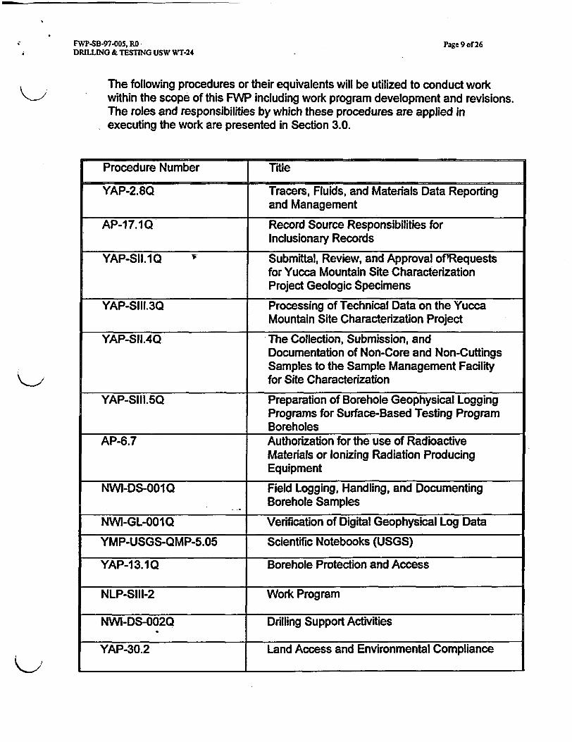
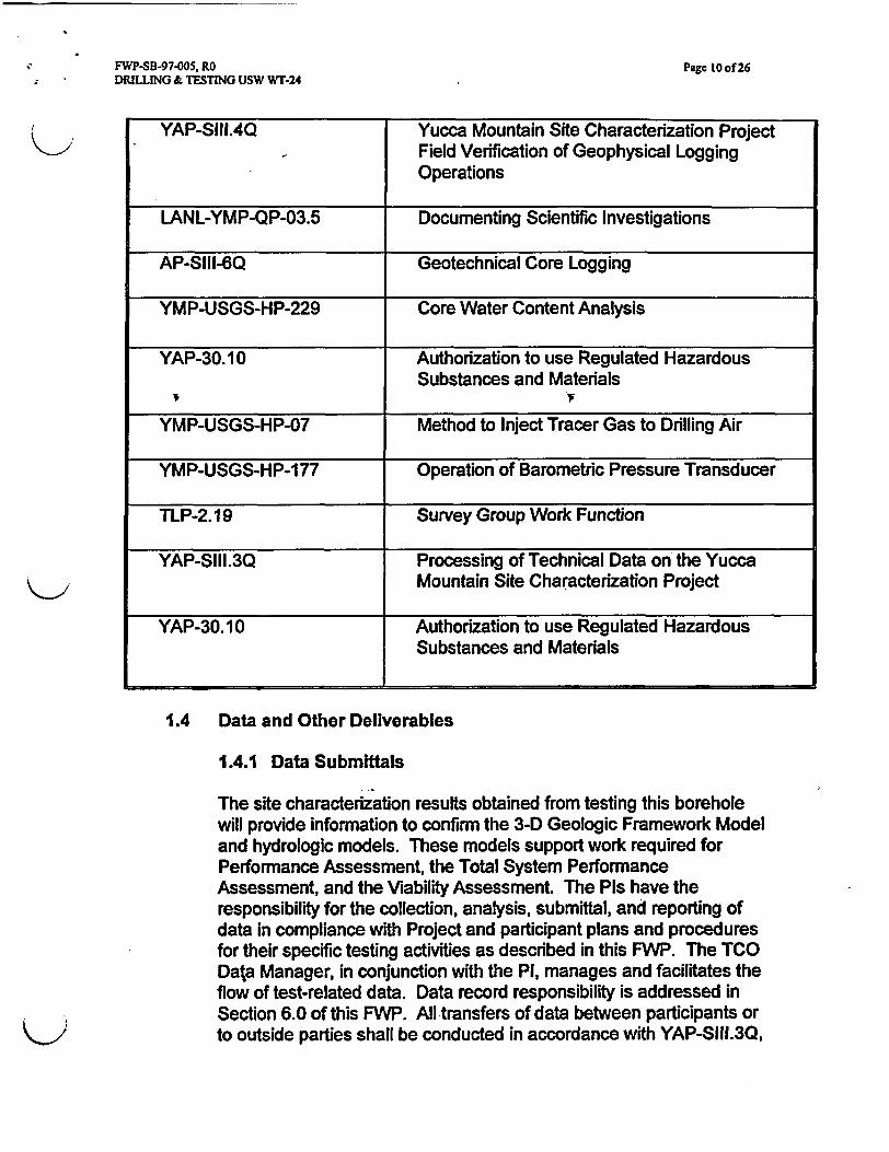
The following procedures or their equivalents will be utilized to conduct workwithin the scope of this FWP including work program development and revisions.The roles and responsibilities by which these procedures are applied inexecuting the work are presented in Section 3.0.
Procedure Number Title
YAP-2.8Q Tracers, Fluids, and Materials Data Reportingand Management
AP-1 7.1Q Record Source Responsibilities forInclusionary Records
YAP-S1.1Q e Submittal, Review, and Approval of Requestsfor Yucca Mountain Site CharacterizationProject Geologic Specimens
YAP-Slll.3Q Processing of Technical Data on the YuccaMountain Site Characterization Project
YAP-SII.4Q The Collection, Submission, andDocumentation of Non-Core and Non-CuttingsSamples to the Sample Management Facilityfor Site Characterization
YAP-S11.5Q Preparation of Borehole Geophysical LoggingPrograms for Surface-Based Testing ProgramBoreholes
AP-6.7 Authorization for the use of RadioactiveMaterials or Ionizing Radiation ProducingEquipment
NWI-DS-001Q Field Logging, Handling, and DocumentingBorehole Samples
NWI-GL-OOIQ Verification of Digital Geophysical Log Data
YMP-USGS-QMP-5.05 Scientific Notebooks (USGS)
YAP-1 3.1Q Borehole Protection and Access
NLP-Slll-2 Work Program
NWI-DS-002Q Drilling Support Activities
YAP-30.2 Land Access and Environmental Compliance
FWP-SB-97005, RODRILLING & TESTING USW WT-24
Page 10 of 26
YAP-SIII.4Q Yucca Mountain Site Characterization ProjectField Verification of Geophysical LoggingOperations
LANL-YMP-QP-03.5 Documenting Scientific Investigations
AP-SIII-6Q Geotechnical Core Logging
YMP-USGS-HP-229 Core Water Content Analysis
YAP-30.10 Authorization to use Regulated HazardousSubstances and Materials
YMP-USGS-HP-07 Method to Inject Tracer Gas to Drilling Air
YMP-USGS-HP-177 Operation of Barometric Pressure Transducer
TLP-2. 19 Survey Group Work Function
YAP-SI11.3Q Processing of Technical Data on the YuccaMountain Site Characterization Project
YAP-30.10 Authorization to use Regulated HazardousSubstances and Materials
1.4 Data and Other Deliverables
1.4.1 Data Submittals
The site characterization results obtained from testing this boreholewill provide information to confirm the 3-D Geologic Framework Modeland hydrologic models. These models support work required forPerformance Assessment, the Total System PerformanceAssessment, and the Viability Assessment. The Pis have theresponsibility for the collection, analysis, submittal, and reporting ofdata in compliance with Project and participant plans and proceduresfor their specific testing activities as described in this FWP. The TCOData Manager, in conjunction with the PI, manages and facilitates theflow of test-related data. Data record responsibility is addressed inSection 6.0 of this FWP. All transfers of data between participants orto outside parties shall be conducted in accordance with YAP-SlIl.3Q,
FWP-SB-97005, RO Page II of 26DRILLING & TESTING USW WT-24
'Processing of Technical Data on the YMP," and other applicableplans and procedures.
1.4.2 Test Deliverables
Mineralogical Support of Phase IIPredicted Occurrence of Erionite in USW WT-24 with 3-DMineralogical Modeling
1.5 Planned Tracers, Fluids, and Materials Usage and Determinationof Importance Evaluation
All work shall be in compliance with DIE for Surface-Based TestingActivities", BAAOOOOOO-01717-2200-00101, Rev. Ob. TFM planned for thedrilling and testing of Borehole USW WT-24 will have been approvedbefore use. Refer to Section 3.2 for contingency plans for TFM usage.Currently approved TFM will be utilized during the drilling and testing ofborehole USW WT-24. The TCO will be responsible for reporting testingTFM. The Constructor/Drilling Service Provider shall record daily wateruse by application and report this information as well as all constructionrelated TFM use/removal. The TCO shall report testing relateduse/removal. TFM reporting will be done in accordance with YAP-2.8Q.TFM Requirements contained in the DlEs shall be applied as QA controlsto limit potential impacts from these activities.
Planned Testing Related TFM:
* LiBr (Non-Q Environmental Tracer). LiBr used is restricted to 20 ppmmaximum to meet State permit concentration levels with a goal of 1.5 to2.5 ppm.
* SF6 (Non-Q Environmental Tracer). SF6 use is limited to 30 ppmmaximum to meet State permit concentration levels.
2.0 SAMPLING PLAN
Sample locations will be identified before drilling begins by the affected Pis,and provided to the TCO. The TCO/Pls will complete YAP-SIl.1Q to allocateall cuttings and core samples.
The current version of YAP-S1.4Q, 'The Collection, Submission, andDocumentation of Non-Core and Non-Cuttings Samples to the SampleManagement Facility for Site Characterization," shall be used to document
FWP-SB-97-005, RODRILLING & TESTING USW WT-24
Page 12 of 266r
sample collection and provide traceability of all water samples taken from theborehole.
The requirements for core samples, sidewall cores, and the collection ofcuttings will be specified by the affected Pis and provided to the TCO beforedrilling of the borehole begins. Core samples will be processed through theSample Overview Committee. Changes to the plan for sampling core andcuttings must be authorized by the affected Pi. The Pi will determine therequirements for technical content and format of the geologic log for theborehole. The Pi will prepare geologic logging procedures and designatethose responsible for preparing the geologic log for the borehole.
Stratigraphic units identified in core will follow the stratigraphic hierarchy andnomenclature as defined in the YMP Reftrence Information Base.
Pi organizations will provide all non-standard sample packaging materials,transportation containers, and any associated equipment prior to the samplecollection activity. Pi organizations will set criteria for all sample types inaccordance with YAP-SI .10.
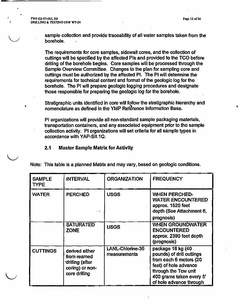
2.1 Master Sample Matrix for Activity
Note: This table is a planned Matrix and may vary, based on geologic conditions.
SAMPLE INTERVAL ORGANIZATION FREQUENCYTYPE
WATER PERCHED USGS WHEN PERCHED-WATER ENCOUNTEREDapprox. 1520 feetdepth (See Attachment 6,prognosis)
SATURATED USGS WHEN GROUNDWATERZONE ENCOUNTERED
approx. 2390 feet depth(prognosis)
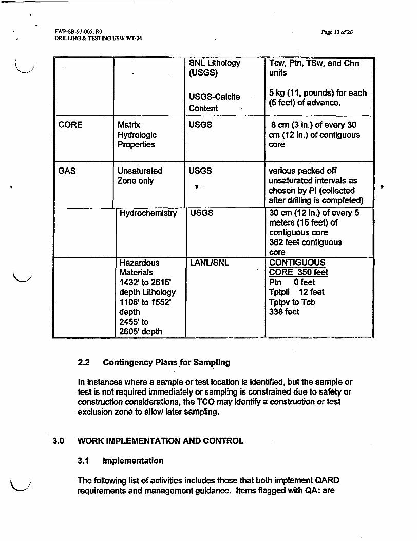
CUTTINGS derived either LANL-Chlorine-36 package 18 kg (40from reamed measurements pounds) of drill cuttingsdrilling (after from each 6 meters (20coring) or non- feet) of hole advancecore drilling through the Tcw unit
400 grams taken every 5'of hole advance through
FWP-SB-97005, RODRILLING & TESTING USW WT-24
Page 13 of 26
SNL Lithology Tcw, Ptn, TSw, and Chn- (USGS) units
USGS-Calcite 5 kg (11, pounds) for eachContent (5 feet) of advance.
CORE Matrix USGS 8 cm (3 in.) of every 30Hydrologic cm (12 in.) of contiguousProperties core
GAS Unsaturated USGS various packed offZone only unsaturated intervals as
chosen by Pi (collectedafter drilling is completed)
Hydrochemistry USGS 30 cm (12 in.) of every 5meters (15 feet) ofcontiguous core362 feet contiguouscore
Hazardous LANUSNL CONTIGUOUSMaterials CORE 350 feet1432' to 2615' Ptn 0 feetdepth Lithology TptpIl 12 feet1108' to 1552' Tptpv to Tcbdepth 338 feet2455' to
__________ 2605' depth
2.2 Contingency Plans for Sampling
In instances where a sample or test location is identified, but the sample ortest is not required immediately or sampling is constrained due to safety orconstruction considerations, the TCO may identify a construction or testexclusion zone to allow later sampling.
3.0 WORK IMPLEMENTATION AND CONTROL
3.1 Implementation
The following list of activities includes those that both implement QARDrequirements and management guidance. Items flagged with QA: are
FWP-SB-97-005, RO Page 14 of 26DRILLING & TESTING USW W1-24
recognized as being quality affecting unless specifically graded out by theorganization performing the task. Items specifically graded out shall beappropriately documented and controlled by the organization performing thetask. Items identified with a QA:NIA do not implement QARD requirementsand are therefore considered administrative in scope. The sequence of QAactivities may be modified by the TCO/FTC based on conditions in the fieldprovided affected organizations concur and those modifications aredocumented.
Work conducted in the field shall be in compliance with the Surface-BasedTesting Facilities Requirements Document (SBTFRD), this document and thework established in the referenced work program.
GENERAL ITEMS' P
QA:NIA TCO and designees will participate in constructors daily toolboxsafety meetings that are held at YMP work sites during each shift. The TCOor designee may also conduct and document an additional, testing specific,toolbox safety meetings as necessary, as agreed to by the CMO.
QA:NIA Pis, SPS personnel, personnel who perform testing activitiesspecific to this FWP shall coordinate field activities through the TCO.
QA:NIA The TCO will serve as point-of-contact for all testing activitiesdefined in this FWP including drilling/coring operations, test installation andData Collection Systems installation.
QA:NIA The CMO will coordinate road maintenance and dust control withthe TCO/SPS to assure safe and adequate access to the worksite.
QA:NWA The TCO shall ensure that FDE, photography, and core loggingservices are provided as needed for the Pi to collect scientific data.
QA:NIA The TCO will initiate and communicate tasks identified in this FWP.
QA:NIA Throughout the implementation of this FWP, the TCO will provideregular written reports to the DOE and M&O Managers addressing testspecific progress.
QA:NIA Ps will provide necessary information to support TCO planning,management, and reporting requirements.
QA: The TCO will check pads and access roads to prevent water pondingthat may enter the borehole. In accordance with DIE controls. This task willbe documented.
FWP-SB-97005, RO Page IS of 26DRILLING & TESTING USW WT-24
QA:NIA The TCO will maintain a presence on behalf of DOE.
QA:NIA PHOTOGRAPHY SUPPORT personnel will take photographs asdirected by the TCO and provide a list of photograph identifiers.
QA:NIA A list of photograph negative numbers supporting this FWP shall besubmitted to the Project RPC by the TCO according to approved Projectprocedures.
QA:NIA The TCO will provide historical borehole information from the drillingreport to the technical database.
QA: The Constzuctor/Drilling Service Provider will perform constructionand test support activities in a manner consistent with the generalconstruction requirements of approved design drawings and specifications.
QA: The TCO will visually check drill pads, test pits, and trenches for changes todrainage characteristics and for evidence of water ponding. These checks will bescheduled to the most restrictive of the following criteria: 1) at least monthlyduring constructiontmaintenance activities, 2) at least yearly during non-sitedisturbing activities, or 3) within 72 hours after 1 inch of liquid precipitation fallswithin a 24 hour period (as measured at meteorlogical station NTS-60).
QA: The ConstructorlDrilling Service Provider will check vehicles forhydrocarbon leaks at least monthly, and will contain, mitigate and repairhydrocarbon leaks in excess of drips from all site sources upon discovery.
QA: The Constructor/Drilling Service Provider shall limit water application to2.6ftlyr, or 0.48 gal/yd2/day unless approved by the Safety AssuranceDepartment and prevent ponding of water.
QA: Affected Organizations may not permanently emplace chlorinelchloride-bearing compounds without documented evaluation and approval by the TCOprior to utilization.
QA: The Constructor/Drilling Service Provider may not use potable water norDUSTAC for dust suppression, nor chlorine-containing salt grounding solutions.
QA: The Constructor/Drilling Service Provider shall grout boreholesconsistent with the criteria identified in the grout plan.
* FWP-SB-97-005, RO Page 16 of 26DRILLING & TESTING USW WT-24
BOREHOLE DRILLING
QA:NIA The CONSTRUCTORIDRILLING SERVICE PROVIDER will supplythe personnel and equipment to drill the borehole including: provide a sumpcatchment system (i.e., a tank or lined pit), provide adequate inner corebarrels and any needed split lines to allow coring operations to proceedwithout interference from coring extraction, logging, and boxing will monitorand provide fuel usage and hours of operations of all NO, producingequipment to M&O EPO on a monthly basis.
QA: The CONSTRUCTORIDRILLING SERVICE PROVIDER will minimizeuse of water when approved for drilling activities and will transfer coresamples to Sample Support Personnel.
QA: The CONSTRUCTORIDRILLING SERVICE PROVIDER will providetraced water in quantities as requested by TCO and record traced water useon a shift basis at the direction of the TCO. Re-circulated water shall not bere-traced with LiBr.
QA:N1A The FDE and/or Constructor/Drilling Service Provider will notifythe TCO immediately if any changes or modifications to the drilling programbased on the work program occur and will document such changes.
QA:NJA The CONSTRUCTORIDRILLING SERVICE PROVIDER will: (1)maintain footage drilled per drill bit; (2) note who is the driller on site duringcoring operations; and (3) report these items on a daily operations report.
QA:N/A The CONSTRUCTORIDRILLING SERVICE PROVIDER willmaintain compliance with the Nevada State permit referenced in Section 8,including providing a Nevada State licensed water well driller.
QA: The INJECTION COORDINATOR is responsible for limitedmaintenance, set-up, and storage of the 'Tracer Gas Injection System" aswell as designating trained personnel to operate the system in accordancewith HP-07 and the State approved Underground Injection Permit (UIC).
QA:NIA During active drilling activities, the INJECTION COORDINATOR orDESIGNEE will check daily the injection equipment to adjust and reportevents associated to the Tracer Gas Injection" system.
QA:NIA FDE staff will note on the daily operations report which InjectionCoordinator or Designee is on site during air coring operations.
QA:N1A The INJECTION COORDINATOR OR DESIGNEE shall ensure thatSF, or other approved tracer, is used to tag drilling air used in any dry
FWP-SB-97-005, RO Page 17 of 26DRILLING & TESTNG USW WT.24
drilled/cored boreholes under the scope of this FWP. At a minimum, they willmonitor the pressure in the SF compressed gas cylinder; monitor the digitalread-out of the power supply connected to the mass flow controller and adjustas necessary; and shut off gas flow when not in use. Generally the digitalreading should be one half of the compressed air flow output connected tothe drill rig.
QA:N/A The TCO will provide on-site direction for drilling transitions to coringand collection of water samples and perched-water/water table testing.
QA: The INJECTION COORDINATOR or Designee will halt drilling/coringoperation when the cylinder pressure drops below 500 psig.
QA:NIA The CONSTRUCTORIDRILLING SERVICE PROVIDER shallensure that two cylinders of compressed SF, be on location at all times. Onecylinder should be in-use and a spare (full) cylinder should be available forchange-out. The Constructor/Drilling Service Provider will supply SF, gasand provide limited maintenance.
QA:NIA If the tracer concentration exceeds the UIC permit level as identifiedor if any problems are encountered, the INJECTION COORDINATOR ORDESIGNEE will halt all dry drilling/coring operations, notify the TCO FieldTest Manager, document the problem, and repair the system if necessary.
QA: The INJECTION COORDINATOR will provide to the SPS writtendocumentation listing total volumes used including concentration of initial gasused for all dry drilling conducted in support of this FWP.
QA:NIA The INJECTION COORDINATOR or TCO is responsible forreporting tracer gas usage and concentrations to the M&O EPD on a monthlybasis.
QA: The CONSTRUCTORIDRILLING SERVICE PROVIDER will survey anddocument the borehole collar locations in accordance with QA procedures.
QA: Affected Organizations shall leave surface casings in place or re-installthem to prevent surface water intrusion into boreholes.
QA: The TCO or designee will visually examine drill core and cuttings forevidence of natural water sources during drilling and notify the Pi if perched-water is suspected.
OA: Upon discovery of perched water, the TCO will stop drilling and invokethe perched water plan developed by the PI.
FWP-SB-97005, RO Page IS of 26DRILLING & TESTING USW WT-24
BOREHOLE TESTING
QA:NIA The TCO will direct activities on geophysical logging.
QA: Pis are responsible for collection, management, and submittal of data,in compliance with Project and applicable PI plans and procedures. Alltransfers of data between YMP Participants, submittal of data to the YMPdatabase, and transfer of data to outside parties shall be conducted inaccordance with YAP-SIII.3Q, Processing of Technical Data on the YuccaMountain Site Characterization Project," and other applicable plans andprocedures.
QA: Borehole gyroscopic surveys will be provided by geophysical loggingsupport at direction of the TCO. W
QA:NIA The CONSTRUCTORIDRILLING SERVICE PROVIDER will providelabor, technical support service, support equipment and materials required fortest instrumentation installation, including grouting, lifting, and access, asdirected, coordinated and scheduled by the TCO.
QA: The Pis affected, or scientific staff may install instrumentation inagreement with the TCO and in accordance with their QA technicalprocedures or scientific notebook procedures.
QA: Upon notification from the TCO, the PI will conduct daily tests for thepresence of free-standing perched-water provided conditions allow for the use ofa moisture probe.
QA: The Pis, or designees, will collect field data in accordance with scientificnotebook procedures identified in Section 1.3 or other applicable QAprocedures.
QA: The PI will transmit initial and reduced data to the records system inaccordance with YAP-SIlil.3Q as identified in Section 6.1 of this FWP.
QA:NIA The PI will request and schedule instrumentation packageinstallation and removal with the TCO.
QA:NIA P organizations will provide an information copy of instrumentationdescription, calibration reference, instrument location and the instrumentsystem unique identifier by physical location to the TCO.
QA: The Affected Organizations shall limit the release of committed organicsubstances in boreholes to no more than 11.24 grams per 20 meters of boreholelength unless approved by the Safety Assurance Department.

FWP-SB-97-005, RO Page 19 of 26DRILLING & TESTING USW wT-24
BOREHOLE SAMPLING
QA: The Pis will accept the Boreholes in writing.
QA:NIA: A list of unique sample numbers shall be provided to the TCO bythe Sample Collection Support and the PI.
QA:NIA The TCO will define and document the disposition of cutting and/orcore generated from drilling/coring activities associated with this FWP asoutlined in procedures YAP-SII.1Q, YAP-SII.2Q, and YAP-SII.4Q. Therecords resulting from these procedures provide the sample collection criteriaincluding sample packaging requirements.
QA: The SAMPLE COLLECTION SUPPORT personnel will collect cutting orcore samples from the Constructor/Drilling Service Provider in accordancewith NWI-DS-001Q.
3.2 Contingency Plans
No foreign material is to be left in or around the borehole following completionof the drilling activity to the extent practical.
Any item lost in the borehole will be evaluated and pursued using fishingoperations for recovery. And if not recoverable, it shall be reported, andrecorded in the TFM database in accordance with YAP-2.8Q.
Every effort shall be made to avoid spilling of fuels, lubricants or coolants into oraround the borehole area. Should spills occur, they should be cleaned up asmuch as practical (e.g., recovery of oil-soaked sand) by the constructor per theirprocedures. Any spilled materials not recovered shall be recorded in terms ofquantity, description of local area impacted, and nature of material spilled. Thisrecord shall be entered into the activities records and reported to the TFMManager in accordance with YAP-2.8Q.
3.3 Prerequisites and Hold Points
N/A3.4 Stop Work
Affected organizations must inform the TCO if quality-related work elementscannot be conducted as described in this FWP. The TCO will, if applicable,stop work on those elements. If FWP revisions are required, work onaffected elements will be stopped until the modifications have beencompleted and controlled by the Project. The Assistant Manager for
Z
FWP-SB-97-005, RO Page 20 of 26DRILUNG & TESTING USW WT-24
Environmental Safety and Health (AMESH) or any individual may stop workfor Safety andHealth-related issues if an imminent danger exists.Employees' rights relating to safety or health imminent danger conditions aredescribed in Section 1.8.3 of the M&O Safety and Health Plan.
4.0 ADMINISTRATIVE (NON-QA) INSTRUCTIONS
4.1 Environment, Safety, and Health
4.1.1 Environment
Environmental ComplianceAll work stlall be in compliance with the Environmental StipulationLetters produced for the activities at the USW WT-24 Borehole.
A Radiation Work Permit (RWP) is requested for use of radioactivematerials. AP-6.7 and Radiological Protection Program will governradiological related-work . State permits may also be required.
4.1.2 Safety and Health
1. General Safety and Health (S&H) requirements apply to this testactivity; there are no specific requirements.
2. Participating organizations shall comply with the requirements ofthe M&O Safety and Health Plan and established M&Oprocedures and rules.
Safety and Health Roles and Responsibilities:The TCO and the M&O for the YMP regards the S&H of all employees tobe of paramount importance. In order to establish and maintain a highdegree of safety and health awareness on the YMP all organizationsand employees involved with the scientific characterization activitiesmust clearly understand their roles and responsibilities in maintaining asafe and healthful workplace.
The responsibility for S&H on the YMP begins with the M&O Contractor,flows down through the M&O CMO, then to the TCO and theConstructor. From these organizations, responsibility flows down to therespective organizations conducting actual work on the YMP, includingscientific characterization organizations, through the umbrella of theM&O Safety and Health Plan. The M&O Safety and Health Planestablishes implementing guidance through written YMP S&H programsand procedures (i.e., Occupational Respiratory Protection, Noise Controland Hearing Conservation).

FWP-SB-97005, RO Page 21 of 26DRILLING TESTING USW WT-24
Responsibility for the S&H of M&O employees flows through M&O linemanagement and each organization's supervision, then ultimatelyto Individual employees.
The Constructorldrilling service provider: The constructor performssupport services for the scientific characterization work being conductedon the YMP. The constructor/drilling service provider has S&Hresponsibility for their own employees, for maintaining the YMP Site in asafe and healthful condition, for maintaining mobile and stationaryequipment, some S&H training, and training in the safe operation ofcertain pieces of equipment. The constructor/drilling service providerwill only maintain a full time presence during drilling activities at allremote worksites on the YMP, but will assist anytme when contacted.The TCO as the M&O manager for field testing activities, and/orassigned scientific organization staff (i.e., LLNL, LBNL, SNL, and/orUSGS) will maintain M&O line management and/or organizationsupervision at the Site at all times.
TEST COORDINATION OFFICE, and other Scientific Organizations:TCO, and other scientific organizations are responsible for the S&H oftheir employees through M&O line management and each organization'ssupervision. When both the TCO and scientific organization linemanagement and supervision occupy a YMP worksite at the same time,the TCO will have S&H coordinating responsibility. When a YMPworksite is not occupied by the TCO, scientific organization linemanagement and each organization's supervision will have S&Hcoordinating responsibility.
TCO, and other scientific organizations always perform work under theM&O Safety and Health Plan, and/or their own organization Safety andHealth Plan.
Organization supervisors are responsible for the workplaceimplementation of S&H standards, codes, regulations Project proceduresand programs.
The TCO, under agreement with the CMO may conduct additionaltesting specific Toolbox Safety meetings during each shift.
Individual M&O Employees: Individual M&O employees, regardless oftheir employer, are responsible for understanding the requirements ofthe safety and health programs of their employer and specific YMP S&Hprograms (i.e., Occupational Respiratory Protection, Noise Control andHearing Conservation, Personal Protective Equipment [PPE).
FWP-SB-97-005, RO Page 22 of 26DRILING & TESTING USW WT-24
Individual M&O employees are responsible for ensuring that the S&Htraining they have received is followed and implemented, regardless ofwhether the training was received from their parent organization or onthe YMP. Individual M&O employees are responsible for immediatelynotifying the construction shift supervisor and their M&O line manager ofunsafe acts, conditions, andlor equipment.
A discussion of the roles and responsibilities addressed in this FWP isalso included in the Safety Review (SR) (Attachment 5) that isconducted by the TCO S&H Specialist.
The SR is an attachment to the FWP and has been compiled in order toevaluate and transmit information on the potential hazards that may beencountered while installing, operatdng and/or maintaining scientificinvestigation equipment or instrumentation on the YMP. Eachorganization's line management and supervision should read the SRand use it as a guideline for informing, educating and implementingprotective measures for the identified hazards. A copy of the SR, LaserOperating Permit, and RWP for the temporary use of radioactivematerials will be available at the TCO field office, the Las Vegas Office,and will be transmitted to test and constructor organizations working onthe YMP.
Employee Training: Personnel requiring access to the YMP ESF Sitemust have completed or be escorted by an individual with GeneralEmployee Training (GET) and First Aid training.
PPE is required for all persons entering any construction site on theYMP (i.e., hard hat, steel toe shoes, approved (ANSI Z87) safetyglasses, and/or hearing protection (plugs or muffs).
In certain areas of the ESF, Occupational Respiratory Protection isrequired. Managers and supervisors should be aware that respirator fittesting is an annual requirement that includes a physical examination.
All participants shall adhere to the Occurrence Reporting andProcessing System for accident reporting in accordance with DOE Order0232.1.
Use of Tracers in excess of State approved levels must be brought tothe attention of the M&O Environmental Department by the TCO assoon as possible.
Hazardous materials (i.e., Erionite) may be encountered above andlorbelow the Topopah Springs vitrophyre during drilling or reaming
FWP-SB-97-005, RODRILLING & TESTING USW WT-24
Page 23 of 26
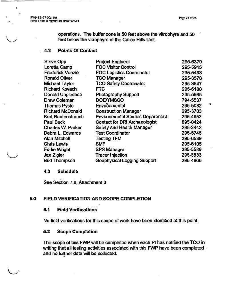
operations. The buffer zone is 50 feet above the vitrophyre and 50feet below the vitrophyre of the Calico Hills Unit.
4.2 Points Of Contact
Steve OppLoretta CampFrederick VenzieRonald OliverMichael TaylorRichard KovachDonald UnglesbeeDrew ColemanThomas PystoRichard McDonaldKurt RautenstrauchPaul BuckCharles W. ParkerDebra L. EdwardsAlan MitchellChris LewisEddie WrightJan ZiglerBud Thompson
Project EngineerFOC Visitor ControlFOC Logistics CoordinatorTCO ManagerTCO Safety CoordinatorFTCPhotography SupportDOENMSCOEnvirtnmentalConstruction ManagerEnvironmental Studies DepartmentContact for DRI ArchaeologistSafety and Health ManagerTest CoordinatorTesting TFMSMFSPS ManagerTracer InjectionGeophysical Logging Support
295-6379295-5915295-5438295-3578295-3647295-6180295-5965794-5537295-5082295-37032954952895-0424295-2442295-5745295-6539295-6105295-5589295-5533295-4866
4.3 Schedule
See Section 7.0, Attachment 3
6.0 FIELD VERIFICATION AND SCOPE COMPLETION
5.1 Field Verifications
No field verifications for this scope of work have been identified at this point.
5.2 Scope Completion
The scope of this FWP will be completed when each Pi has notified the TCO inwriting that all testing activities associated with this FWP have been completedand no further data will be collected.
FWP-SB-97-005, RODRILLING & TESTING USW WT-24
Page 24 of 26
6.0 RECORDS
6.1 Records Identification
Pls are responsible for collection, management, and submittal of data, incompliance with Project and applicable PI plans and procedures. All transfersof data between YMP Participants, submittal of data to the YMP database, andtransfer of data to outside parties shall be conducted in accordance with YAP-S111.3Q, "Processing of Technical Data on the Yucca Mountain SiteCharacterization Project," and other applicable plans and procedures.
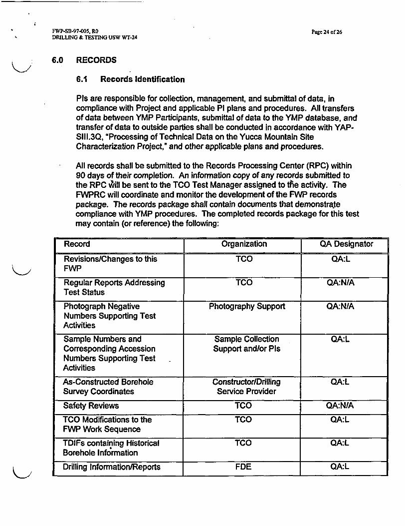
All records shall be submitted to the Records Processing Center (RPC) within90 days of their completion. An information copy of any records submitted tothe RPC ,ill be sent to the TCO Test Manager assigned to the activity. TheFWPRC will coordinate and monitor the development of the FWP recordspackage. The records package shall contain documents that demonstratecompliance with YMP procedures. The completed records package for this testmay contain (or reference) the following:
Record Organization QA Designator
Revisions/Changes to this TCO QA:LFWP
Regular Reports Addressing TCO QA:N/ATest Status
Photograph Negative Photography Support QA:N/ANumbers Supporting TestActivities
Sample Numbers and Sample Collection QA:LCorresponding Accession Support and/or PisNumbers Supporting TestActivities
As-Constructed Borehole Constructor/Drilling QA:LSurvey Coordinates Service Provider
Safety Reviews TCO QA:N/A
TCO Modifications to the TCO QA:LFWP Work Sequence
TDIFs containing Historical TCO QA:LBorehole Information
Drilling Information/Reports FDE QA:L
FWP-SB-97-005, RODRILLING & TESTING USW WT-24
Page 25 of 26
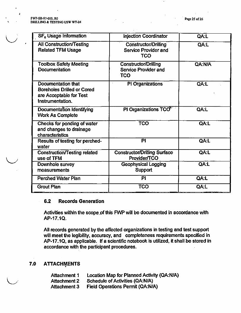
SF. Usage Information Injection Coordinator QA:L
All Construction/Testing Constructor/Drilling QA:LRelated TFM Usage Service Provider and
TO
Toolbox Safety Meeting Constructor/Drilling QA:NIADocumentation Service Provider and
TCO
Documentation that Pi Organizations QA:LBoreholes Drilled or Coredare Acceptable for TestInstrumentation.
Documentation Identifying PI Organizations TC6 QA:LWork As Complete
Checks for ponding of water TCO QA:Land changes to drainagecharacteristicsResults of testing for perched- Pi QA:LwaterConstruction/Testing related Constructor/Drilling Surface QA:Luse of TFM Provider/TCODownhole survey Geophysical Logging QA:Lmeasurements Support
Perched Water Plan Pi QA:L
Grout Plan TCO QA:L
6.2 Records Generation
Activities within the scope-of this FWP will be documented in accordance withAP-17.1Q.
All records generated by the affected organizations in testing and test supportwill meet the legibility, accuracy, and completeness requirements specified inAP-17.1Q, as applicable. If a scientific notebook is utilized, it shall be stored inaccordance with the participant procedures.
7.0 ATTACHMENTS
Attachment 1Attachment 2Attachment 3
Location Map for Planned Activity (QA:N/A)Schedule of Activities (QA:NIA)Field Operations Permit (QA:N/A)
FWP-SB-97-005, RO Page 26 of 26DRILLING & TESTING USW WT-24
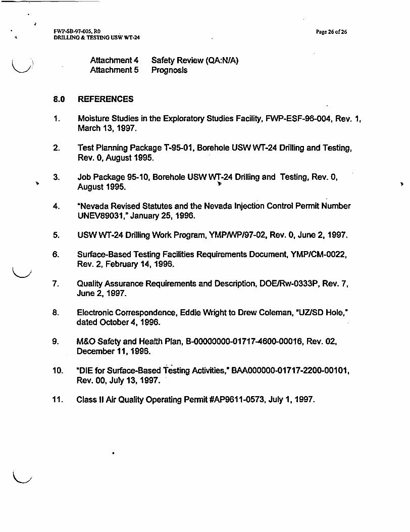
Attachment 4 Safety Review (QA:NIA)K> Attachment 5 Prognosis
8.0 REFERENCES
1. Moisture Studies in the Exploratory Studies Facility, FWP-ESF-96-004, Rev. 1,March 13,1997.
2. Test Planning Package T-95-01, Borehole USW WT-24 Drilling and Testing,Rev. 0, August 1995.
3. Job Package 95-10, Borehole USW WT-24 Drilling and Testing, Rev. 0,August 1995.
4. 'Nevada Revised Statutes and the Nevada Injection Control Permit NumberUNEV89031," January 25, 1996.
5. USW WT-24 Drilling Work Program, YMPiWP/97-02, Rev. 0, June 2, 1997.
6. Surface-Based Testing Facilities Requirements Document, YMP/CM-0022,Rev. 2, February 14, 1996.
7. Quality Assurance Requirements and Description, DOEIRw-0333P, Rev. 7,June 2, 1997.
8. Electronic Correspondence, Eddie Wright to Drew Coleman, UZSD Hole,"dated October 4, 1996.
9. M&O Safety and Health Plan, B-00000000-01717-4600-00016, Rev. 02,December 11, 1996.
10. "DIE for Surface-Based Testing Activities, BAAOOOOOO-01717-2200-00101,Rev. 00, July 13, 1997.
11. Class II Air Quality Operating Permit #AP9611-0573, July 1, 1997.

FWP-SB-97-005. RO Attachment 1DRILLING &TESTING USWWr-24 2 Pages
LOCATION MAP FOR PLANNED ACTIVITY
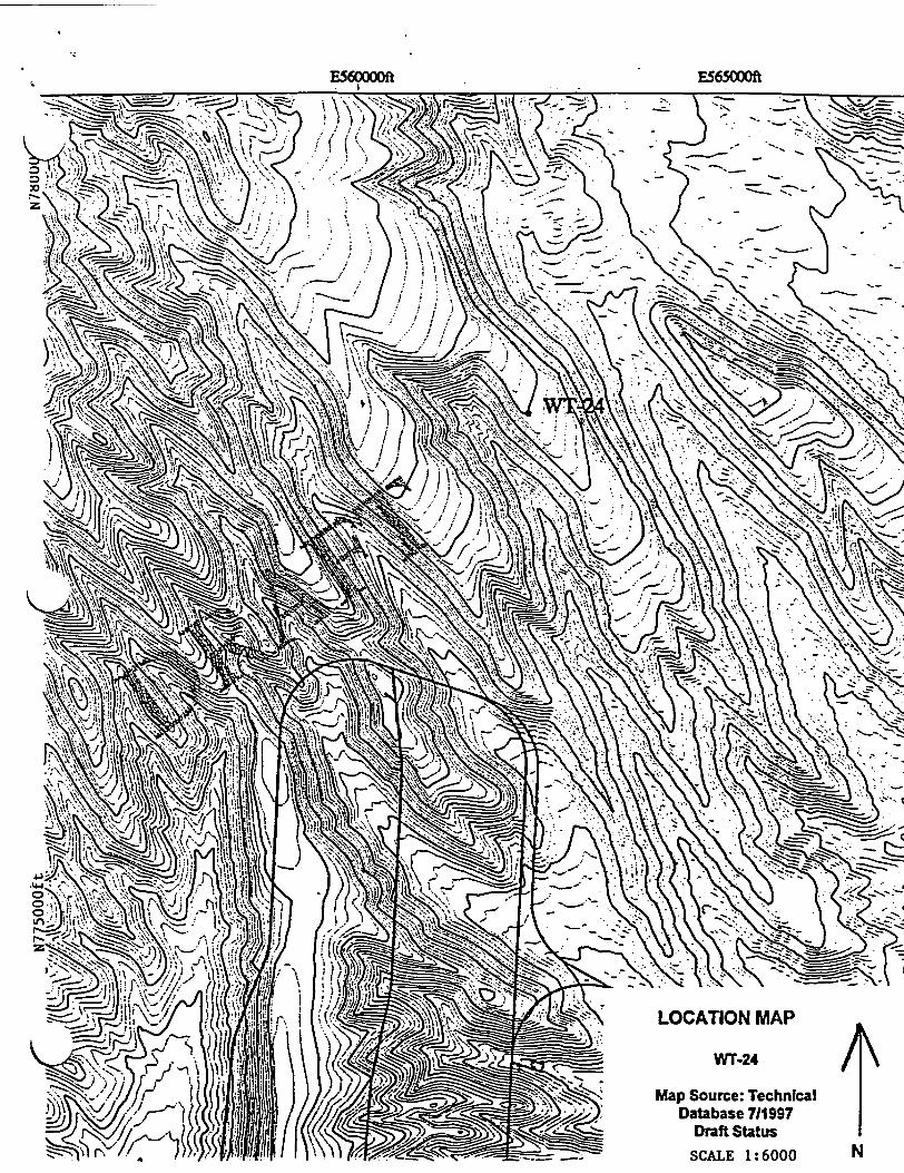
E565000ft
LOCATION MAP
/WT-24
Map Source: TechnicalDatabase 711997
Draft Status
SCALE 1:6000 N
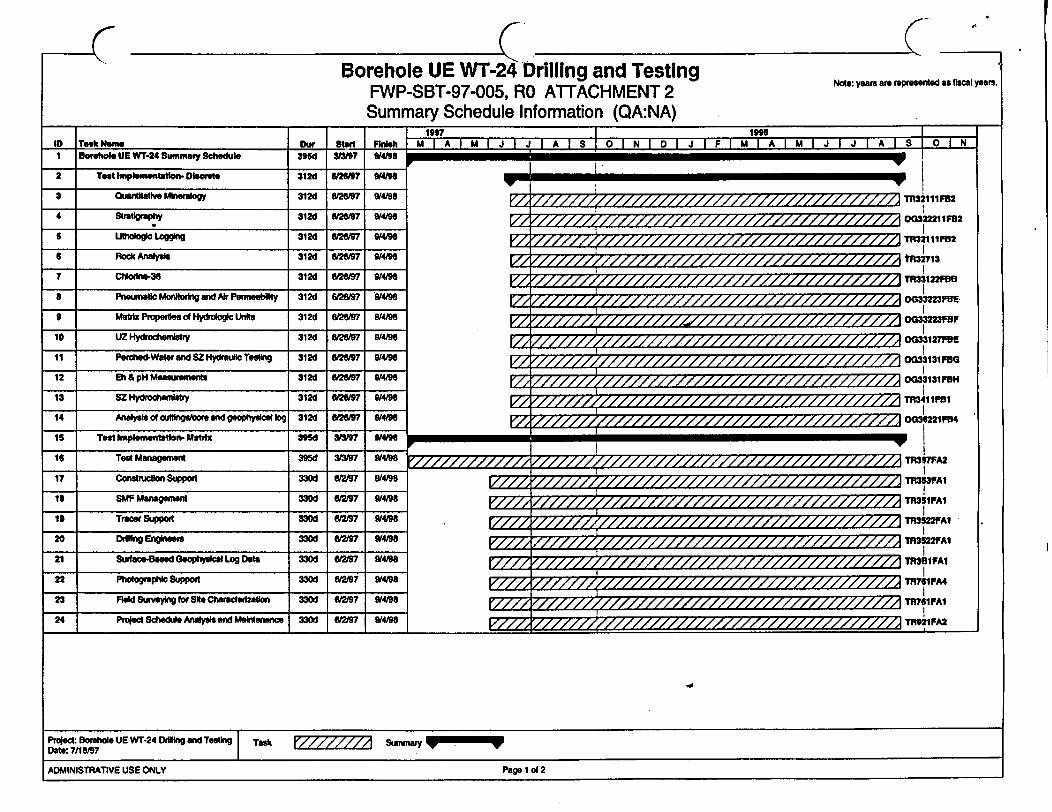
Borehole UE WT-24 Drilling and TestingFWP-SBT-97-005, RO ATTACHMENT 2Summary Schedule Information (QA:NA)
Note: yeas are represented as fiscal years.
.
FinihIn Took un" .v I Rn1 Bohole UE WT-24 Summy Schedub 395d WII9 W4"8
2 Test Imp ementetion- Discret 312d 647W _/4/0
3 uNitt Mineralogy 312d 6wr /4/98
4 Stratgrephy 3t2d 26197 /4/98
5 L.thologlo Logging 312d 6197 /498
6 Rock Analysis 312d W26/9 /4/98
7 Chlohln36 3126 6/97 V4/98
8 Pneumatic Moniting and Air Pemnsebity 312d 66/97 /4/98
9 Matdtx Properties d Hyrologic Units 312t 6/26/97 9/4/96
10 UZ Hyftchemistry 312d 6/ 197 0/4/98
11 Perched-Water and SZ Hydreulic Test 3126 6/17 0/4/98
12 Eh & pH Measurements 3126 6/97 W4
13 SZ Hydrocherstry 3126 6/97 9/4/9
14 Analysis of cuflings/core and geophysical log 312d 6126/97 9/4198
1 5 Tes Implemxentalo t 395d 3/3? O4"
M A M AJ I J I A I S O N D M J I f M A M I J J I A S O 1
EZ~~~~~~~~~~~~~~~~~'
OG32221tF2
7Z W 5TR3211tFB2
r/Z111A tR32713
7Z2 TR33122F8
OG33223FE
/Z /////////////// G0"33223FBF
0033127F
0033113111FO0
OG33131FH
/EZ//////i//////////////////////// /////7//7TR341IF81
0036221FA4TR397FA2
TR3S1FA
/1///////,//////t////////z//z/////////////>TR31 PAl
r////g//////i//////////////////////////////mTR3522PA1
F////8//////////////////////////////////////|TR3722FA1
TR7G/A4
TR?61FAI
TR92tFA2
18 Teal Managerent 395d 04196I I I I
17 Conction Spot W 6t2 97 U/94
is SMF Managemet 330d 61219? 9/4198
19 Trace Support 330d 62197 9/4196
20 Ddilng Engineers 330d 6/2197 9M196
21 Surface-aed Geophysical Log Dale 330d 62/97 W49
22 Photongraphic Support 330d 6/2197 W4/98
23 FReld Surmaying for Site Charaerzaton 330d /2197 419
24 Project Schedule Analysis an Maintenance 330d I 297 O/4WI I I
Proect Bole UE WT-24 Drg and Testig Tasx surnrnay k WDate: 7/1819
ADMINISTRATIVE USE ONLY Page d 2ADMINISTRATIVE USE ONLY Page 1 of 2
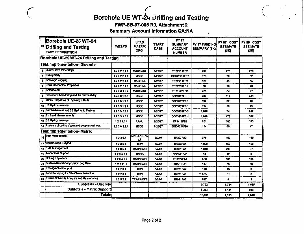
C Borehole UE WT- Lrilling and TestingFWP-SB-97-005 RO, Attachment 2
Summary Account Information QA:NA
Borehole UE-25 WT-24 LEAD FY9 FY 97 COST FY 98 COSTID1 WSS MATRIX START SUMMARY FY 97 FUNDING ESTIMATE ESTIMATEDrilling and Testing ORG. DATE ACCOUNT SUMMARY ($K) (K (SK)
TASK DESCRIPTION NUMBER _____(S_)
Borehole UE-25 WT-24 Drilling and TestingTent Implementation- Discrete
3 Q0uantitative Mineralogy 1.2.3.2.t.1.1 M&O/LANL 626/97 TR32111 FB2 780 273 273
4 Str*WlaphY 1.2.3.2.2.1.1 USGS 6/26/W7 OG322211FB2 176 79 62
5 Lithologic Logging 1.2.3.2.2.1.1 M&O/SNL 626l97 TR32111FB2 100 45 35a Rock Mechanical Propertes 1.2.3.2.7.1.3 M&/SNL 6/26197 TR32713FB1 SO 28 28
7 Chlrine-36 1.2.3.3.1.2.2 M&O/LANL 6/2697 TR33122FBB 768 84 77
a Pneumatic Monitoring and Air Permeability 1.2.3.3.1.2.3 USGS U2ei97 0G33223FBE 704 317 246
g Matrix Properties of Hydrologic Unts 1.2.3.3.1.2.3 USGS /97 OG33223FBF 137 62 48
10 UZ Hydrochemistry 1.2.3.3.1.2.7 USGS 6/2697 OG33127FBE 124 66 43
E Perched-Water and SZ Hydraulic Testing 1.2.3.3.1.3.1 USGS 6/267 0G33131FBG 1,049 74 247
2 Eh & pH Measurements 1.2.3.3.1.3.1 USGS 6/2697 OG33131FBH 1,049 472 367
13 SZ Hydrochernistry 1.2.3.4.11 LANL 6/26/97 TR341I FBI 651 163 163
14 Analysis of cuttingscore and geophysical logs 1.2.3.6.2.2.1 USGS /97 OG36221FB4 134 60 47
Test Implementation- Matrix
16 Test Management 1.2.3.9.7 M&O/LANLNW 3/2/97 TR397FA2 376 169 169, e s M a a e et.. . . C F _ _ _ _ _ _ _ _ _ _ _
17 Contction Suppio= 1.2.3.5.3 TRW 6/2/97 TR353FA1 1,000 450 450
I SMF Management 1.2.3.5.1 M&O/ SAIC 6/297 TR35IFAI 1,610 290 97
19 Tracer Gas Support 1.2.3.5.2.1 USGS 6/i97 OG3521FA1 80 12 0
2| Drilling Engineers 1.2.3.5.2.2 M&O/ SAIC 6/2/97 TR3522FA1 500 105 105
21 Surfae-Based Geophysical Log Data 1.2.3.11.1 M&O/ SAIC 6/2/97 TR381FA1 117 53 53
22 Photographic Support 1.2.7.6.1 TRW 6/2/97 TR761FA4 128 13 0
| Field Swueying for Site Characterization 1.2.7.6.1 TRW 8/2/97 TR761FA1 " 505 51 0
24 Project Schedule Analysis and Maintenance 1.2.9.2.1 TRW7WCFS 6/2/97 TR921FA2 917 9 9
Subtotals - DIscrete 5,752 1,714 1 635
Subtotals - Matrix Support 5,233 , 1,151 683
Totals7 10,985 2,865 2,518
Page 2 of 2

FWP-SB-97-005, RO Attachment 3DRILLING & TESTING USW Wr-24 I Page
FIELD OPERATIONS PERMIT
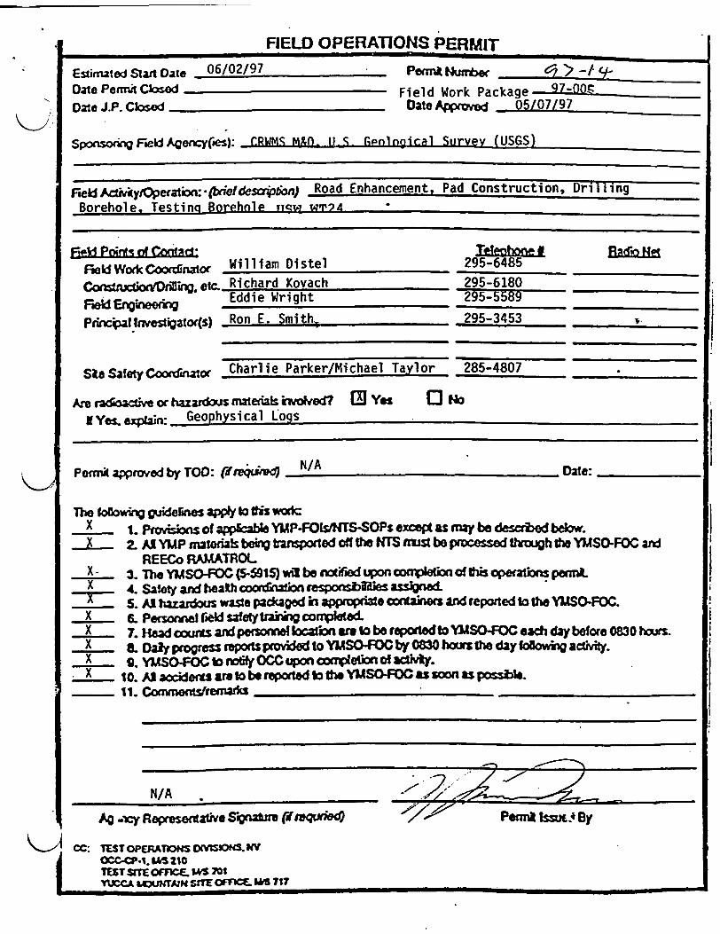
FIELD OPERATIONS PERMIT
Etinuted Stan Date 06/02/97Date Permi Cbsd_Date J.P. Cksed
- PomfnA Number ,* > -tv-Field Work Package 97-00-QOate Approved 05/07/97
SponsokVFedAgency(es): CRWM M(. S rtpongical Survev (USGS)
Fee lAcvy/Opention :_tie!desa.p6ba) Road Enhancement, Pad-Constructi D ilgBorehole, Testing Borehole Tyqw wr74
fekl Ponts of ContFeid Wor of CnAto( William Distel
ConcstuaorvDtiki.etc. Richard Kovach
F Enedkn Eddie Wright
Pdxial nvestigato(s) Ron E. Smith,
SlsSafety CooeCdnato Charlie Parker/Michael Taylor
Tetelq #295-6485295-6180
295-3453 If
285-4807
Anre acfso e or hazardous materah ktvolved? [M Yet
NYemexpan: Geophysical ogs
0 No
Peffrapparoved by TOO: (ane*)to N/A Date:-
The oaowuV guidefines ap* to #is woscX 1. P;rovns of apable YUP-fOMs&WTS-SOPs exceg as may be descrbed below.X 2. Al YIP mateials bei bnsponed off the HNS mis be processed sWugh the YMSO-FOC ad
REECo RAMATROLX 3. The YMSO-FOC (5-5t5) wl be auife upon cnpletkon of Ofis oporatbis pemLX 4. Safety ard heath coon l tion, poesbiaes assgnwedX S. Al haardus waste packaged in approptizate ootinrs nd reported to the YLSCFOC.X . Personnel f*d safety takig coar5eted.X 7. Had courts and pmonnief Iaion are to be repoto SOFOC each day before 0830 hours.
X . Daly pcogr reots pvkdd to YMSOFOC by 0830 hours the day awig ad *.X 9. YllSOiFOC to noly OCC ipon Wompletil of adtvy.X 10. AJ aociderat are to be report b the YMSOFOC as sn as possbie
11. Com mentsfre___s
N/A
AO XT Representawi Sivnawre ( t7qxie) Pefni Issxx. By
c C: TEST OPERATOPS O .MS. kVOCC-.1. SM 210TEsT STE OfCE. &4% 70YUCCA LCuT SffE OFFICE MG 717

FWP-SB-97-005. RO Attachment 4Drilling & Testing USW WT-24
SAFETY REVIEW OF FIELD WORK PACKAGE FWP) FORDRILLING AND TESTING USW WT-24
1.0 INTRODUCTION
This Safety Review (SR) has been compiled by the Test Coordination Office(TCO) to evaluate the potential hazards that may be associated with Drilling andTesting of USW WT-24. This SR is also being conducted to ensure thatinformation about potential hazards will be transmitted to all affectedorganizations, TCO employees, and constructor organizations working at theUSW WT-24 Borehole Site.
1.1 EQUIPMENT SCOPE AND SCOPE
This SR will provide guidance for scientific personnel conducting GeophysicalLogging, Perched Water Sampling, Hydrologic Testing and MineralogicalEvaluations at the USW WT-24 Borehole Site. The USW WT-24 borehole will beUdry drilled" using the Stratmaster Drill Rig. The planned core size for theborehole is approximately 2.4 inches, with compressed air being used as thedrilling fluid.
A tracer gas (Sulfur Hexafluoride/SF6 ) will be added to the drilling air. Corecuttings, water, and core samples will be collected from the borehole.Hydrochemical and hazardous materials (i.e., Erionite) will be sampled.
Testing at the USW WT-24 borehole will consist of Geophysical Logging anddownhole videos, Hydrologic tests will include hydraulic tests (i.e., pumpingand/or bailing of the borehole, monitoring the potentiometric surface, andcollecting hydrochemical samples. Mineralogical evaluations include assessingalteration history and fracture mineralogy.
A detailed description of all data collection system activities can be found in FieldWork Package (FWP-SB-97-005).
2.0 HAZARDS
2.1 SITE SPECIFIC HAZARDS
Potential hazards to surface-based testing personnel conducting StratmasterDrill Rig Activities and Borehole Testing Activities on the YMP are:
1
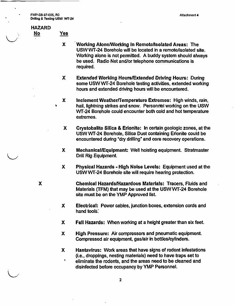
FWP-SB-97-005, RO Attachment 4Drilling & Testing USW Wr-24
HAZARDNo Yes
X Working AlonelWorking in Remotellsolated Areas: TheUSW WT-24 Borehole will be located in a remote/isolated site.Working alone is not permitted. A buddy system should alwaysbe used. Radio Net andlor telephone communications isrequired.
X Extended Working Hours/Extended Driving Hours: Duringsome USW W`-24 Borehole testing activities, extended workinghours and extended driving hours will be encountered.
X Inclement Weather/Temperature Extremes: High winds, rain,hail, lightning strikes and snow. Personnel working on the USWWT-24 Borehole could encounter both cold and hot temperatureextremes.
X Crystobalite Silica & Erionite: In certain geologic zones, at theUSW WT-24 Borehole, Silica Dust containing Erionite could beencountered during "dry drilling" and core recovery operations.
X Mechanical/Equipment: Well hoisting equipment. StratmasterDrill Rig Equipment.
X Physical Hazards - High Noise Levels: Equipment used at theUSW Wr-24 Borehole site will require hearing protection.
X Chemical HazardslHazardous Materials: Tracers, Fluids andMaterials (TFM) that may be used at the USW WT-24 Boreholesite must be on the YMP Approved list.
X Electrical: Power cables, junction boxes, extension cords andhand tools.
X Fall Hazards: When working at a height greater than six feet.
X High Pressure: Air compressors and pneumatic equipment.Compressed air equipment, gas/air in bottles/cylinders.
X Hantavirus: Work areas that have signs of rodent infestations(i.e., droppings, nesting materials) need to have traps set toeliminate the rodents, and the areas need to be cleaned anddisinfected before occupancy by YMP Personnel.
2
FWP-SB-97-005, RO Attachment 4Drilling & Testing USW Wr-24
X Radiation: Neutron sources will be used to conduct wirelineborehole logging operations.
X Fire: No hazards identified at this time.
X Walking and Working Surfaces: Slips, trips and falls.
3.0 HAZARD CONTROLS
Working Alone/Working In Remotellsolated Areas: The USW WT-24Borehole site is located in a remotefisolated area. Therefore field work shall be
- conducted in teams of two or more persons. Use of the buddy system ismandatory. The scientific personnel conducting borehole activities shall be intwo-way communications (either by radio and/or phofe) with a base station (i.e.,ESF TCO-295-3483, Net #5 Radio; or Ranch Control-295-5915, YMP#1 RadioNet) and established a regular check-in schedule.
At the beginning and end of daily borehole activities, scientific personnel need tocheck in with Ranch Control and the ESF TCO with a head count of personnel.
Personnel conducting USW WT-24 Borehole activities should never venture intothe field without a radio, first aid kit, and water.
For life-threatening injuries or medical emergencies, on the NTS Radio Network,call Mayday, Mayday, Mayday". Ranch Control also has to be notified.
Extended Working Hours/Extended Driving Hours: During some USWWT-24 Borehole testing activities extended working and extended driving hours willbe encountered. Whenever possible, personnel conducting borehole activitiesshould utilize the "buddy system". Transportation, back and forth to the boreholesite should be done in pairs (or more) riding together in a single vehicle. Findsomeone to ride with who will stay awake and monitor your driving.
Nevada State Law requires you to wear seat belts, and U.S. Department ofEnergy requires you to wear a seat belt if you are driving a government vehicle.Drivers of vehicles are responsible for ensuring that passengers wear their seatbelts.
Inclement Weather/Temperature ExtremeslSunbums: Personnel conductingUSW Wr-24 Borehole activities could encounter severe inclement weather (rain,lightning strikes, and/or high winds) with little or no warning.
Sunburn is a very define possibility if you are going to be outside most of theday. Always wear uSun screen", long pants and long sleeved shirt.
3

FWP-SB-97-005, RO Attachment 4Drilling & Testing USW Wr-24
NTS Net Radio Control ("9O0") monitors the National Weather Service forconditions on the test site, and broadcasts them over all radio nets on the NTS,including the YMP site. Borehole security personnel should have YMP Net 1radios with them when they go into the field in order to monitor U900U weathercontrol. If severe weather warnings and/or lightning strikes are issued,personnel should suspend work and take cover inside vehicles or leave the sitealtogether. At certain times of the year, severe cold and hot temperatures couldbe routinely encountered at borehole sites.
In cold environments: The objective of preventing USW WT-24 Boreholepersonnel from experience the effects of cold stress is centered aroundpreventing the deep body (core) temperature from falling below 36 degrees C(96.8 degrees F). For a single, occasional exposure to a cold environment, adrop in core temperature to no lower that 35 degrees C (95 degrees F) ispermitted.
Lower body temperatures will very likely result in reduced mental alertness,reduction in rational decision making, or loss of consciousness with the threat offatal consequences.
In protecting borehole security personnel from the effects of cold stress, thefollowing items should be noted:
* Pain in the extremities may be the first early warning of danger to cold stress.
* Suits and cold weather gear should provide whole body protection, withemphasis on hands, feet and head from cold injury.
• The higher the wind speed and the lower the temperature in the work area,the greater the insulation value of the protective clothing required.
* If fine work is to be performed with bare hands for more than 10-20 minutesin cold conditions below 16 degrees C (60.8 degrees F), special provisionsshould be established for keeping employees hand's warm (i.e., fuel bumers,warm air jets, electric radiators).
* If USW WT-24 Borehole work involves the use of evaporativechemicals/liquids (i.e., gasoline, alcohol, or cleaning fluids), then specialprecautions should be taken to avoid soaking of clothing or gloves with theliquids because of the added danger of cold injury due to evaporative cooling.
* If work'at the borehole sites needs to be performed contiguously intemperatures that are below -7 degrees C (19.4 degrees F) then a Work-Warming Regimen" must be established and implemented.
4
FWP-SB-97-005, RD Attachment 4Drilling & Testing USW WT-24
Controlling Cold Stress:Personnel conducting USW WT-24 Borehole activities can find guidance forworking in cold environments and for work/rest regimens in the 1993-1994Threshold Limit Values Booklet for Chemical Substances and Physical Agentspublished by the American Conference of Governmental Industrial Hygienist(ACGIH).
In hot environments: Temperatures in Area 25 can reach 120 degrees F in thehottest part of the summer. Working in these hot work conditions/environmentswith elevated humidity readings will produce elevated heat stress levels. Inconditions such as these, three types of emergencies can occur that involve heatstress; heat cramps, heat exhaustion and heat stroke.
Personnel conducting USW WT-24 Borehole activities should be aware of thefollowing symptoms of heat stress and accompanying first aid treatments:
Heat Cramps:Symptoms:1. Muscle cramps in legs and abdomen.2. Pain accompanying cramps.3. Profuse sweating.4. Faintness.First Aid Treatment:1. Move to cool (air conditioned) place.2. Sip salted water (1 teaspoon of salt in 1 quart).3. Massage cramped muscles.4. Obtain medical treatment.
Heat Exhaustion:Symptoms:1. Profuse sweating.2. Intense thirst from dehydration.3. Cool, moist skin (clammy and pale).4. Fatigue, weakness, dazed.5. Dizziness.First Aid Treatment:1. Move to cool (air conditioned place).2. Loosen tight clothing and remove excess clothing.3. If conscious, sip salted water.4. Treat for shock, lay on back and raise feet slightly.5. Stay with the victim until medical aid arrives.
5
FWP-SB-97-005, RO Attachment 4Drilling & Testing USW WT-24
Heat Stroke:(Please note: Heat Stroke Is a medical emergency)Symptoms:1. Can occur suddenly, with little warning.2. Dizziness, raging headache.3. Hot, dry, flushed skin.4. Full and fast pulse.5. Breathing deep at first, later shallow breathing.6. High temperature (106 degrees or higher).7. Confused delirious behavior.8. Muscle twitching, growing into convulsions.9. Loss of consciousness or coma.
Emergency Care:1. Heat Stroke is a true medical emergency, arrange transport to a medical
facility without delay.2. Move to cool (air conditioned) place.3. Strip to underclothes.4. Lay on back, head and shoulders raised slightly.5. Assure breathing airway is open.6. Put ice or cold wet cloth on head.7. Cool body with water or wet cloth.8. Do not give coffee, cigarettes or a stimulant.
Controlling Heat Stress: Personnel conducting USW WT-24 Borehole activitiesshould:
* Follow scheduled worktrest cycles. Guidance for work/rest regimens can befound in the 1993-1994 Threshold Limit Values Booklet for ChemicalSubstances and Physical Agents, published by the ACGIH.
* Workers should alternate between light and heavy work.* Where possible, rotate duties among several workers.* Drink plenty of water. Drink at least 16 ounces about an hour before and then
5 to 7 ounces every 15-to 20 minutes during work. Some people findelectrolyte drinks (i.e., Gatorade) effective instead of, or in addition to water.
* Encourage workers to wear loose fitting, light-colored clothes wheneverpossible.
Personnel conducting USW WT-24 Borehole activities should drink plenty ofliquids and take frequent breaks. M&O Safety and Health Department procedure,NAP-SH-008, Occupational Heat Stress, provides guidance for dealing withpotential heat stress conditions and establishes responsibilities within the M&O.
Crystobalite, Silica & Erionite: There are several crystalline silica minerals(i.e., quartz, cristobalite and erionite) that may be encountered while conducting
6
FWP-SB-97-005, RO Attachment 4Drilling & Testing USW WT-24
'dry drilling" operations at WT-24 on Yucca Mountain that are classified by theInternational Research Agency on Cancer (IARC) as uprobable' humancarcinogens.
As reported in the "Distribution of Potentially Hazardous Phases of theSubsurface at Yucca Mountain, Nevada"(LANL #LA-12573-MS) the mineral"Erionite" has been found in geologic zones that have been identified by previousdrilling activities. The Stratmaster Drilling activities at the WT-24 Borehole sitecould penetrate some of these zones that contain Erionite.
Erionite may pose a risk if encountered in sufficient quantity even when standardmodem Stratmaster "Dry" Drilling practices are followed, due to its apparentlyextremely high carcinogenic potential. However, erionite occurrence at YuccaMountain appears to be restricted to zones immediately below the potentialrepository horizon. Consequently, it may only be a concem where the ESFworkings may penetrate into the basl vitrophyre of the Topopah Spring Member.
Predicting the Occurrence of Erionite in the WT-24 Borehole is part of the "testdeliverables" that have been developed for the FWP at WT-24.
The Wr-24 Borehole will be drilled to a depth of 2800 ft. At depths determinedby the geologists, sampling and analysis for Potentially Hazardous Minerals" willbe conducted.
When the WT-24 Borehole reaches a depth of 1424 ft (50 ft above thevitrophyre) to 1616 ft (50 ft below the vitrophyre) or as directed by the boreholesite geologist, an Erionite Control Zone will be established at the Stratmasterequipment site.
The Erionite Control Zone will consist of work practices, engineering,administrative and personnel protective equipment control measures.
A. The following engineering controls will be used to control drilling dustthrough the Erionite Control Zone:
* The Stratmaster Dust Collection System.
* The Haz-Vac.
* Maintaining negative pressure on the dust collection system.
B. Administrative controls will involve the establishment of an Erionitecontrol zonelexclusion area and Decontamination Area. Inside thecontrol zone/exclusion area personnel will be required to wear respirators andother PPE as outlined in Section 1.6. This area will encompass the following:
7
FWP-SB-97-005, RO Attachment 4Drilling & Testing USW WT-24
* Area around the Stratmaster Dust Collection System (or Haz-Vac, ifused), the conveyer, and cuffing pit.
* Area used by personnel assigned to remove the core catcher and corefrom the inner barrel.
* Area for core extruding, processing/transmittal, and packaging of coreand/or core cuttings. This area must be large enough to allow forcleaning and vacuuming of core boxes.
* Area for decontamination of personnel and equipment and donningand doffing of PPE. This area should have a shower enclosure.
* (See 1.7 below).
* In addition, a buffer zone will be established approximately 20' wideoutside the Erionite control zone/exclusion area. No one will beallowed in this area, since it serves as a buffer zone to the area wherePPE must be worn.
C. The Decontamination Area for personnel and equipment coming fromworking inside the control zone/exclusion area shall have the followingfeatures:
* A "de-con" area for removal and disposal of PPE.
* A shower enclosure. The shower enclosure may be located with oneend in the regulated area, and the other end outside the regulatedarea.
* Area for storage of street clothes and an area for donning PPE.
* A personal hygiene area, (i.e., hand washing station).
D. The following administrative controls will be effect inside the controlzone/exclusion area:
* Personnel will not be allowed to remove respirators or PPE to eat,drink, smoke, andlor chew tobacco.
* Work-rest routines will be worked out for all personnel throughsupervision. These routines will allow for personnel to remove PPEand respirators and take rest/food breaks outside the controlloneexclusion area.
* Good work place hygiene practices.8
FWP-SB-97-005, RO Attachment 4Drilling & Testing USW WT-24
E. Inside the control zone/exclusion area the following Personal ProtectiveEquipment and Occupational Respiratory Equipment will be worn at alltimes:
* A full face Powered Air Purifying Respirator (PAPR) with HEPA (HighlyEfficient Particulates and Aerosols) Filter.
* Respirator selection, issue and use shall conform to the requirementsof M&O Safety and Health Department Procedure NAP-SH-009"Respiratory Protection".
* A uTyvek" disposable full body overall, longsleeve with booties" andhood.
* Two pairs of gloves (inner-surgical)(outer-work). The inner and outergloves must be taped.
F. The following Industrial Hygiene sampling and monitoring shall beconducted while the Stratmaster drill rig passes through the Erionite ControlZone:
* Full shift employee Breathing Zone and Area Sampling for thepresence of crystalline silica minerals (i.e., quartz, cristobalite anderionite).
G. Hazard Communication Employee Training. All employees (regardless ofemployer) shall receive Hazard Communication Employee Training thatconforms to the M&O Safety and Health Department Procedure NAP-SH-003"Compliance with the OSHA Hazard Communication Standard" beforebeing assigned to the WT-24 site. In addition to this M&O "Haz-Com"Training, WT-24 employees shall receive the following site specific'components:
* A description of the chronic and acute nature of the physical healthhazards involved with crystalline silica minerals (i.e., quartz,cristobalite and erionite) that could be encountered within the drillingdust of the Erionite Control Zone at the WT-24 site.
* A description of the work practices, engineering, administrative andpersonal protective equipment control measures that are employedspecifically at the WT-24 (Stratmaster) site.
9
FWP-SB-97-005, RO Attachment 4Drilling & Testing USW wT-24
H. Medical Surveillance. Supervisors and employees wearing respirators havespecific responsibilities/actions under the respirator program. Employeesmust have completed a physical examination within the past year.
WT-24 personnel requiring physical exams in order to wearoccupational respiratory equipment should follow the guidelines thatcan be found in the M&O Safety and Health Department ProcedureNAP-SH-007 "Medical Surveillance". This procedure describes therequirements for medical surveillance and how M&O employees canarrange for physical examinations, on site through Bechtel NevadaMedical.
M&O Contractor Safety and Health Procedure, NAP-SH-009, RespiratoryProtection, describes the respiratory protection program. Supervisors andemployees Wearing respirators have several specific responsibilities under thisprocedure. Employees must have completed a physical examination within thepast year, and have no facial hair that interferes with the sealing surface of therespirator. M&O Safety and Health Procedure, NAP-SH-007, MedicalSurveillance, describes how M&O employees arrange for physical examinationsconducted on-site through Bechtel Nevada Medical. To schedule a physicalexamination, call 702-295-2957.
Mechanical: When USW WT-24 Borehole activities require scientific personnelto climb onto any piece of equipment, the equipment must first be locked andtagged out.
The Lockout-Tagout program is required by OSHA. It ensures that any time anytype of work has to be done on electrical circuits and/or equipment withmechanical systems or components (i.e., hoisting equipment, drill rig equipment)they have to be deenergized, isolated, and rendered inoperative beforeemployees can begin work. The program requires that the control circuits tothese pieces of equipment be locked and tagged out to prevent accidentalactivation. Contact the TCO Field Test Representative (FTR) to arrange Lockout-Tagout assistance with the Constructor.
Before working around drilling equipment, attend the Constructors ToolboxSafety Meeting that is held at the beginning of each shift. During the meeting,check with the Constructors Drilling Forman and his personnel operating theequipment to ensure they know of your presence and that a daily safetyinspection/equipment check has been done.
Physical Hazards - High Noise Levels: Personnel conducting USW WT-24Borehole activities need to be aware that some of the areas around the site willbe classified as high noise level areas. Hearing protection (ear plugs and/or earmuffs) must be used at all times and in all areas of these sites. Ear plugs and ear
10
FWP-SB-97-005, RO Attachment 4Drilling & Testing USW WT-24
muffs are available from the portal guard at the entrance to the tunnel. Ear muffsare available from the Constructor's Tool Crib located on the ESF Pad. Duringcertain operations, (i.e., drill rig operation) dual protection, both ear plugs and earmuffs, may be required. Contact the TCO Safety and Health Specialist forinformation on locations and activities where dual protection may be required.
The M&O Safety and Health Department Procedure NAP-SH-004"Occupational Noise Protection" specifies the requirements for employeesworking in high noise level areas. All employees working in these areas must bein a "Hearing Conservation Program" and, among other things obtain a baselineand annual audiogram (hearing test).
Chemical: Any chemicals and materials used for Perched-Water Sampling,Hydrologic Testing, and/or Mineralogical Evaluations will be provided by theConstructors Tool Crib. Other Tracers, Fluids and Materials (TFM) that could bepart of testing activities will be on the ESF approved list for materials that can betransported and used on the YMP.
A Determination of Importance Evaluation (DIE) has been completed in support ofplanned TFM usage. They capture any controls or constraints identified throughthe DIE process in the field implementing documentation.
The use or removal of testing-related TFM by affected organizations must beidentified and reported to the TCO prior to such use or removal. The TCO ES&HSpecialist coordinates the annual inventory of hazardous chemicals, as requiredby OSHA regulation and the M&O Safety and Health Department Procedure,NAP-SH-003, Compliance with the OSHA Hazard Communication Standard.The affected organization must know the location of the Material Safety DataSheets (MSDS), and the proper storage, use, transportation and PersonalProtective Equipment (PPE) requirements for all the hazardous chemicals theyuse. The MSDS should always be reviewed before using any product or materialunderground. Contact M.F. Taylor, TCO ES&H Specialist, if there are questionsregarding TFM usage in the ESF.
Electrical Hazards: Personnel who conduct USW WT-24 Borehole activities willnote that High Voltage cable(s) will be lying on the ground. Casual contact withpower cables is not a safety concem. However, if the nature of any testingactivity could cause physical damage to electrical cable jacket(s) or conductors, itis mandatory that the TCO FTR be contacted to arrange with the Constructor tohave the cable(s) moved. Do not attempt to open or work on any electricalcomponent. Contact the TCO FTR to obtain the services of the Constructor'selectricians. All electrical systems must be locked and tagged out before anywork can be attempted.
If

FWP-SB-97-005. RO Attachment 4Drilling & Testing USW WT-24
All USW WT-24 Borehole site electrical outlets will be 3-phase grounded OSHAStandard. All electrical outlets and cords at the USW WT-24 Borehole site areeither part of an Assured Grounding Program or Ground Fault Circuit Interrupt(GFCI) protected. The Assured Grounding Program uses a color coding systemthat is changed every quarter (3 months) on extension cords and equipment.Contact the TCO FTR for assistance in getting equipment, tools, and extensioncords entered into the Assured Grounding Program.
Fall Hazards: Scientific personnel conducting USW WT-24 Borehole activitieswho have to work at a height greater than six (6) feet off the ground, must eitherwork behind OSHA approved scaffolding with guard rails (top rail minimum height,42, mid-rails, toeboards), or use OSHA approved fall protection equipment. Thisincludes a body harness, lifelines, Sala Block and/or lanyards.
OSHA approved ladders (set at an tngle of between 75 and 90 degrees) shouldalways be used. Do not attempt to crawl up the side of a piece of equipmentwithout fall protection aids. Approved fall protection equipment is available on theESF Pad from the Constructor's Tool Crib. Harnesses and lanyards must beattached to structural components that will support at least 5,000 pounds.Contact the TCO FTR to make arrangements for getting the proper fall protectionequipment.
High Pressure: Personnel conducting USW WT-24 Borehole activities couldencounter air compressors, pneumatic equipment, and gas/air in bottles/cylinders. Never walk under or around any of this equipment while it is inoperation.
Compressed air will be used as the drilling fluid on the Stratmaster Drill Rig aspart of dry drilling scientific characterization activities. Air compressors and airreceivers (storage tanks) should be equipped with pressure reliefvalves/apparatuses. Air hoses should be equipped with whip checks whichprevent accidentally separated hoses from thrashing about, injuring employees.Never attempt to tighten, remove or adjust any compressed air or gasequipment, lines, or pipes while the components are pressurized. Compressedair equipment, lines, or pipes should be equipped with bleed down valvesto ensure that all air pressure Is relieved before attempting to tighten,remove or adjust any components. No work should ever be attempted on anysystem, lines, or components that are live or charged. Large K bottles orcylinders which contain 200 cubic feet of compressed gas may be encounteredat the USW WT-24 site. These cylinders are used for such operations asoxygen/acetylene cutting and tracer gas injection. In general, any cylinder that isnot being used should be stored in an upright position, secured to a rack with achain, and have the protective cap over the cylinder valve. Cylinders should betransported using a cart that is designed for this purpose.
12
FWP-SB-97-005, RO Attachment 4Drilling & Testing USW WT-24
Hantavirus: An outbreak of a potentially fatal illness has occurred in theSouthwest, primarily in New Mexico and Arizona, although two cases have beenreported in Central Nevada.
The cause of the illness has been identified by the Center for Disease Control(CDC) as the Hantavirus.
Hantavirus is usually transmitted by contact with rodent saliva, urine, or feces.Rodents such as pocket mice, deer mice, canyon mice, and kangaroo rats arethe primary carriers.
A study in 1993 by the CDC on the NTS found that only the deer mice populationwas infected, and the infections existed only at higher elevations on the NTS(i.e., Pahute Mesa, Rainier Mesa). No infected rodents were found in Area 25locations.
As a precaution, all scientific personnel on the Yucca Mountain SiteCharacterization Project (YMP), working in field locations should be aware of thepossibility of exposure to the Hantavirus and follow this advice:
* Avoid human contact with rodents, rodent droppings, rodent nestingmaterials. Infected rodents carry the virus in saliva, urine and feces. Nevertouch a live or dead rodent.
* The virus can infect humans through breathing the dust of dried out rodentfeces and urine, and contact with rodent feces/urine through skin that is cut,dried or broken. Avoid breathing the dust from rodent infested areas, avoidskin contact with rodent infested areas.
* If a facility in which scientific personnel are working has visible signs of"heavy" rodent infestations (i.e., rodent excreta (droppings) and/or rodentnests, the rodents should be trapped/removed and the facility cleaned anddisinfected.
* Scientific personnel should make no attempt to remove or clean-up rodentinfested areas. Kiewit/PB Industrial Hygiene has personnel that are trained inpest control techniques, and they have the expertise, equipment, andsupplies to trap and cleanup heavy infestations.
Contact R. Kovach to arrange for the services of Kiewit/PB Industrial Hygiene.
Radiation: Neutron sources will be used to log the USW WT-24 Borehole atselected time intervals. Authorization for the use of these ionizing radiationproducing materials will be through the M&O Radiation Control (RADCON)Manager, and will be in accordance with YMP Administrative Procedure (AP-6.7).
13
* FWP-SB-97-005, RO Attachment 4Drilling & Testing USW WT-24
All RADCON operations will be conducted in accordance with the NVYMPRADCON Manual and the M&O Radiation Protection Program andImplementation Plan (RPP).
A Radiological Work Permit (RWP) will be issued before any activity involving theuse of radioactive materials/tools is permitted. Radiological Health Surveys willbe conducted during the use of these radioactive materials/tools. RadioactiveMaterial Areas (RMA) with controlled access will be established duringdeployment. Signage, posting and barricade requirements will be in effect. Foottraffic may be restricted or limited during calibration and insertion activities insideand around the RMA. Any employee required to be inside the RMA will at aminimum, have General Employee Radiation Training (GERT) and Rad Worker ITraining. Any employee inside the RAM will have the following personalmonitoring devices: NTS Whole Body Thermoluminescent Dosimeter (TLD) andNeutron Dosimeter. Personnel handling the tool and related accessories willwear finger TLDs.
Fire: The high fire hazard season at the Nevada Test Site usually runs fromspring to fall. Brush fires have been started by lightning strikes. Fires have alsobeen started by vehicle's exhaust pipes coming into contact with brushes whileoff-road driving. Vehicle exhaust pipes can reach 500 degrees F or more. Whilethe likelihood of such fires is remote, personnel conducting borehole activitiesneed to remain alert to such fire hazards and report any fire as soon as it issighted using the "900 Radio Net Control" to call the fire station. Personnelshould carry fire extinguishers and shovels.
Walking and Working Surfaces: Personnel conducting USW WT-24 Boreholeactivities should be aware that most borehole sites have rocky, gravel or dirtsurfaces. These areas have gaps and irregularities on the walking surface. Slips,trips, and falls could be hazardous.
4.0 ROLES AND RESPONSIBILITIES - SAFETY AND HEALTH
4.1 SAFETY AND HEALTH ROLES AND RESPONSIBILITIES
The TCO and the M&O Contractor for the YMP regards the Safety and Health(S&H) of all employees to be of paramount importance. In order to establish andmaintain a high degree of S&H awareness on the YMP, all organizations andemployees involved with the scientific characterization activities must clearlyunderstand their roles and responsibilities in maintaining a safe and healthfulworkplace.
The responsibility for S&H on the YMP begins with the M&O Contractor, flowsdown through the CMO, then to the TCO and the Constructor. From theseorganizations, responsibility flows down to the respective organizations
14
* FWP-SB-97-005, RO Attachment 4Drilling & Testing USW WT-24
conducting actual work on the YMP, including scientific characterizationorganizations, through the umbrella of the M&O Safety and Health Plan.
Responsibility for the S&H of YMP employees flows through M&O linemanagement and each organization's supervision, then ultimately toindividual M&O Employees.
The Constructor: The Constructor and/or Drilling Contractor performs supportservices for the scientific characterization work being conducted on the YMP.The Constructor, as the constructor organization, has S&H responsibility for theirown employees, for maintaining the YMP Site in a safe and healthful condition,for maintaining mobile and stationary equipment, some S&H training, and trainingin the safe operation of some limited pieces of equipment. The constructor willonly maintain a full time presence during drilling activities at all remote worksiteson the YMP, but will assist anytime when contacted. The TCO as the M&Omanager for field testing activities, and/or assigned scientific organization staff(i.e., LLNL, LBNL, SNL, and/or USGS) will maintain M&O line managementand/or organization supervision at the Site at all times.
TEST COORDINATION OFFICE, and other Scientific Organizations: TCO,and other scientific organizations are responsible for the S&H of their employeesthrough M&O line management and each organization's supervision. When boththe TCO and scientific organization line management and supervision occupy aYMP worksite at the same time, the TCO will have S&H responsibility. When aYMP worksite is not occupied by the TCO, scientific organization linemanagement and each organization's supervision will have S&H responsibility.
TCO and other scientific organizations always perform work under the M&OSafety and Health Plan, and/or their own organization's Safety and Health Plan.
TCO line managers and organization supervisors are responsible for theworkplace implementation of S&H standards, codes, regulations Projectprocedures and programs.
The TCO, under agreement with the CMO, may conduct additional testing specificToolbox Safety Meetings at the beginning of each shift.
Individual M&O Employees: Individual M&O Employees, regardless of theiremployer, are responsible for understanding the requirements of the S&Hprograms of their employer and specific YMP S&H programs (i.e., OccupationalRespiratory Protection, Noise Control and Hearing Conservation, PPE).Individual M&O Employees are responsible for ensuring that the S&H trainingthey have'received is followed and implemented, regardless of whether thetraining was received from their parent organization or on the YMP. IndividualM&O Employees are responsible for immediately notifying the construction shift
15
FWP-SB-97-005, RO Attachment 4Drilling & Testing USW Wr-24
supervisor and their M&O and the Construction Shift Supervisor line manager ofunsafe acts, conditions, and/or equipment. Organization supervisors areresponsible for ensuring that their employees attend the Constructor's ToolboxSafety Meeting that is held at the beginning of each shift.
TCO Safety Review (SR): The SR is an attachment to the FWP and has beencompiled in order to evaluate and transmit information on the potential hazardsthat may be encountered while installing, operating and/or maintaining scientificinvestigation equipment or instrumentation on the YMP. Each organization's linemanagement and supervision should read the SR and use it as a guideline forinforming, educating and implementing protective measures for the identifiedhazards. A copy of the SR and RWP for the temporary use of radioactivematerials will be available at the TCO field office, the Las Vegas Office, and willbe transmitted to test and constructor organizations working on the YMP.
4.2 EMPLOYEE TRAINING
Personnel requiring access to the YMP bore sites must have completed or beescorted by an individual with General Employee Training (GET) and First Aidtraining.
PPE is required for all persons entering any construction site on the YMP (i.e.,hard hat, steel toe shoes, approved (ANSI Z87) safety glasses, and/or hearingprotection (plugs or muffs). Casual dress (shorts, no shirt, sandals) is not allowedat YMP borehole sites. Work shirts (short sleeve or long sleeve if your worriedabout sunburn), long pants are the normal attire. M&O Safety and HealthDepartment Procedure NAP-SH-002 "Procurement of Required PersonalProtective Equipment" describes how M&O employees go about obtainingprescription safety glasses and approved footwear through the M&O purchasingsystem.
All participants shall adhere to the M&O Safety and Health Procedure NAP-SH-001 "Occupational Injury/ilnesslProperty Damage Reporting andInvestigation" for guidance on occurrence reporting and processing ofinformation through the DOE system.
4.3 OTHER TRAINING
All personnel entering YMP borehole sites who have not received the shift toolbox briefing are to ask if a Constructor Supervisor is on site and receive thebriefing from that person. This is to ensure compliance with applicableOccupational Safety and Health Administration (OSHA) Standards.
16
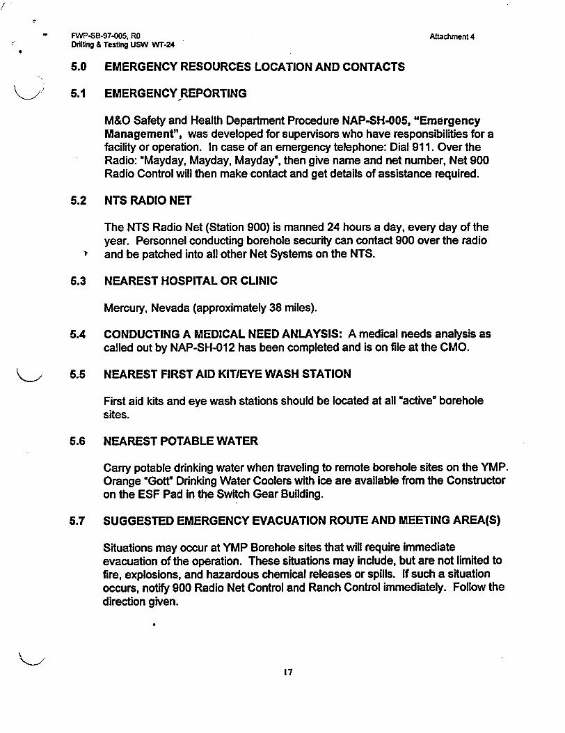
- FWP-SB-97-005. RO Attachment 4Drilling & Testing USW Wr-24
5.0 EMERGENCY RESOURCES LOCATION AND CONTACTS
5.1 EMERGENCY REPORTING
M&O Safety and Health Department Procedure NAP-SH-005, "EmergencyManagement", was developed for supervisors who have responsibilities for afacility or operation. In case of an emergency telephone: Dial 911. Over theRadio: "Mayday, Mayday, Mayday", then give name and net number, Net 900Radio Control will then make contact and get details of assistance required.
5.2 NTS RADIO NET
The NTS Radio Net (Station 900) is manned 24 hours a day, every day of theyear. Personnel conducting borehole security can contact 900 over the radio
> and be patched into all other Net Systems on the NTS.
5.3 NEAREST HOSPITAL OR CLINIC
Mercury, Nevada (approximately 38 miles).
5.4 CONDUCTING A MEDICAL NEED ANLAYSIS: A medical needs analysis ascalled out by NAP-SH-012 has been completed and is on file at the CMO.
5.5 NEAREST FIRST AID KIT/EYE WASH STATION
First aid kits and eye wash stations should be located at all uactive" boreholesites.
5.6 NEAREST POTABLE WATER
Carry potable drinking water when traveling to remote borehole sites on the YMP.Orange "Got Drinking Water Coolers with ice are available from the Constructoron the ESF Pad in the Switch Gear Building.
5.7 SUGGESTED EMERGENCY EVACUATION ROUTE AND MEETING AREA(S)
Situations may occur at YMP Borehole sites that will require immediateevacuation of the operation. These situations may include, but are not limited tofire, explosions, and hazardous chemical releases or spills. If such a situationoccurs, notify 900 Radio Net Control and Ranch Control immediately. Follow thedirection given.
17
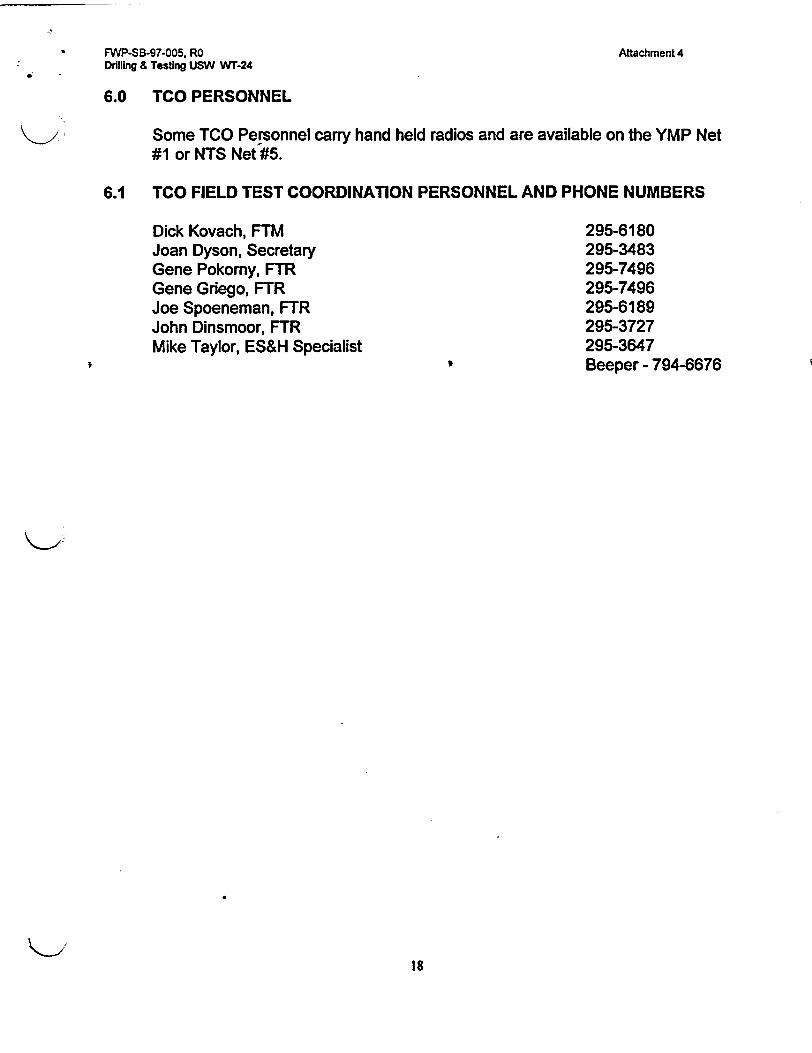
FWP-SB-97-005. RODrilling & Testing USW WT-24
Attachment 4
6.0 TCO PERSONNEL
Some TCO Personnel carry hand held radios and are available on the YMP Net#1 or NTS Net #5.
6.1 TCO FIELD TEST COORDINATION PERSONNEL AND PHONE NUMBERS
Dick Kovach, FTMJoan Dyson, SecretaryGene Pokomy, FTRGene Griego, FTRJoe Spoeneman, FTRJohn Dinsmoor, FTRMike Taylor, ES&H Specialist
295-6180295-3483295-7496295-7496295-6189295-3727295-3647Beeper - 794-6676
18
FWP-SB-97-005, RO Attachment 5DRILUNG & TESTING USWWT-24 2 Pages
PROGNOSIS
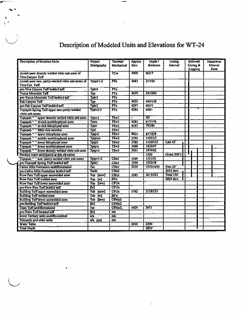
Description of Modeled Units and Elevations for WT-24
Description of Modeled Units Project Thermal/ Approx. Depth I Coring Sidewall HazardousStratigraphy Mechanical Elev. thickness Interval Coring & Mineral
Logging Zonecrystal-poor densely welded vitric sub-zonc of TCw 4900 01217Tiva Canyon Tuff _crystal-poor non- partly-welded vitric sub-zones of Tpcpvl-2 PTn 4683 217124Tiva Cyn. Tuffpre-Tiva Canyon Tuff bedded tuff Tpbt4 PTn _
Yucca Mountain Tuff Tpy PTn 4659 2411204 _
pre-Yucca Mountain Tuff bedded tuff Tpbt3 PTn _Pah Canyon Tuff Tpp PTn 4455 445/15Spre-Pah Canyon Tuff bedded tuff Tpbt2 PTn 4297 603/5Topopah Spring Tuff upper non-partly-welded Tp~t2-3 PTn 4292 608/- _vitric sub-zonesTopopah " "upper densely welded vitric sub-zone Tptrvl TSwI - NPTopopah " " xl-rich nonlithophysal zone Tptm TSwl 42S3 617/176 _
Topopah " Al-rich lithophysal zone Tptrl TSwl 4107 793184 _
Topopah " " lithic rich member Tptf TSwI _
Topopah " " upper lithophysal zone Tptpul TSwI 4023 8771228 _
Topopah " "middle nonlithophysal zone Tptpmn TSw2 3795 1105/15 _
Topopah " "lower lithophysal zone Tptptl TSw2 3780 11201312 Last 12'Topopah "" lower nonlithophysal zone Tptpln TSw2 3468 1432/47Topopah " lower densely welded vitric sub-zone Tptpv3 TSw3 3421 1479/52Perched water anticipated at this elevation 1520 (Total 200')Topopah" "non- partly-welded vitric sub-zones Tptpvl-2 CHnl 3369 1531/21pre-Topopah Spring Tuff bedded tuff Tpbtl CHnl 3348 1552/18Calico Hills Formation undifferentiated Tac CHnI 3330 157011045 First 20'pre-Calico Kills Formation bedded tuff Tacbt CHn2 2455 elev. __
Prow Pass Tuffupper nonwelded zone Tcp [unwi CHn3 2285 2615/523 Total 15 _
Prow Pass Tuff welded zone Tcp [wI PPw 2605 elev. _I_____Prow Pass Tuff lower nonwelded zone Tep [Inwi CFUn _pre-Prow Pass Tuff bedded tuff [bti CFUn _
Bullfrog Tuff upper nonwelded zone Tcb [unwi CFUn 1762 3138/333Bullfrog Tuff welded zone Tb [wi BFw _Bullfrog Tuff lower nonwelded zone Tcb [Inwl CFMnl _pre-Bullfrog Tuff bedded tuff [bti CFMn2 _Tram Tuff undifferentiated Tct CFMn2, 1429 3471 _ Ipre-Tram Tuff bedded tuff Ibtl n/a =lower Tertiary units undifferentiated n/a - - nla =Palcozoic and older units ala fpzj nla _
Water Table 2410 2390 =Total Depth 3850'
Related Documents