CDOT Drainage Design Manual Energy Dissipators 11-1 CHAPTER 11 ENERGY DISSIPATORS TABLE OF CONTENTS 11.1 INTRODUCTION............................................................................................................................ 2 11.2 DESIGN CRITERIA ....................................................................................................................... 2 11.2.1 Dissipator Type Selection ........................................................................................................... 2 11.2.2 Design Limitations ...................................................................................................................... 5 11.2.3 Design Options............................................................................................................................ 5 11.2.4 Related Designs .......................................................................................................................... 6 11.3 DESIGN PHILOSOPHY................................................................................................................. 6 11.3.1 Overview..................................................................................................................................... 6 11.3.2 Alternative Analysis.................................................................................................................... 6 11.3.3 Design Methods .......................................................................................................................... 7 11.3.4 Types of Scour ............................................................................................................................ 7 11.3.5 Scour Hazard............................................................................................................................... 7 11.3.6 Dissipator Types ......................................................................................................................... 8 11.3.7 Computational Methods .............................................................................................................. 8 11.4 DESIGN EQUATIONS ................................................................................................................... 8 11.4.1 General ........................................................................................................................................ 8 11.4.2 Approach ..................................................................................................................................... 9 11.5 DESIGN PROCEDURE ................................................................................................................ 11 11.5.1 Overview................................................................................................................................... 11 11.6 RIPRAP BASIN ............................................................................................................................. 15 11.6.1 Overview................................................................................................................................... 15 11.6.2 Design Procedure ...................................................................................................................... 15 11.7 IMPACT BASIN USBR TYPE VI................................................................................................ 20 11.7.1 Overview................................................................................................................................... 21 11.7.2 Elements of Design ................................................................................................................... 21 11.7.3 Design Procedures .................................................................................................................... 25 REFERENCES.......................................................................................................................................... 29

DrainageDesignManual Chapter11 EnergyDissipators (1)
Dec 14, 2015
DrainageDesignManual Chapter11 EnergyDissipators (1)
Welcome message from author
This document is posted to help you gain knowledge. Please leave a comment to let me know what you think about it! Share it to your friends and learn new things together.
Transcript
CDOT Drainage Design Manual Energy Dissipators
11-1
CHAPTER 11 ENERGY DISSIPATORS
TABLE OF CONTENTS
11.1 INTRODUCTION............................................................................................................................ 2
11.2 DESIGN CRITERIA ....................................................................................................................... 2
11.2.1 Dissipator Type Selection ........................................................................................................... 2 11.2.2 Design Limitations...................................................................................................................... 5 11.2.3 Design Options............................................................................................................................ 5 11.2.4 Related Designs .......................................................................................................................... 6
11.3 DESIGN PHILOSOPHY................................................................................................................. 6
11.3.1 Overview..................................................................................................................................... 6 11.3.2 Alternative Analysis.................................................................................................................... 6 11.3.3 Design Methods .......................................................................................................................... 7 11.3.4 Types of Scour ............................................................................................................................ 7 11.3.5 Scour Hazard............................................................................................................................... 7 11.3.6 Dissipator Types ......................................................................................................................... 8 11.3.7 Computational Methods.............................................................................................................. 8
11.4 DESIGN EQUATIONS ................................................................................................................... 8
11.4.1 General........................................................................................................................................ 8 11.4.2 Approach..................................................................................................................................... 9
11.5 DESIGN PROCEDURE ................................................................................................................ 11
11.5.1 Overview................................................................................................................................... 11
11.6 RIPRAP BASIN ............................................................................................................................. 15
11.6.1 Overview................................................................................................................................... 15 11.6.2 Design Procedure ...................................................................................................................... 15
11.7 IMPACT BASIN USBR TYPE VI................................................................................................ 20
11.7.1 Overview................................................................................................................................... 21 11.7.2 Elements of Design ................................................................................................................... 21 11.7.3 Design Procedures .................................................................................................................... 25
REFERENCES.......................................................................................................................................... 29

CDOT Drainage Design Manual Energy Dissipators
11-2
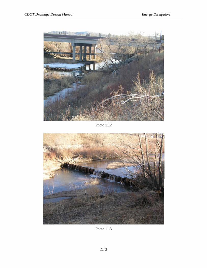
11.1 INTRODUCTION The failure or damage of many culverts and detention basin outlet structures can be traced to unchecked erosion. Erosive forces, which are at work in the natural drainage network, are often exacerbated by the construction of a highway or by other urban development. Interception and concentration of overland flow and constriction of natural waterways inevitably results in an increased erosion potential. To protect the culvert and adjacent areas, it is sometimes necessary to employ an energy dissipator. Energy dissipators are any device designed to protect downstream areas from erosion by reducing the velocity of flow to acceptable limits. This chapter provides criteria and procedures for designing energy dissipators at our culvert outlets. Most of the design criteria and procedures are based on FHWA Hydraulic Engineering Circular Number 14 (HEC 14), Hydraulic Design of Energy Dissipators for Culverts and Channels.
Photo 11.1
11.2 DESIGN CRITERIA
11.2.1 Dissipator Type Selection
The dissipator type selected for a site must be appropriate to the location. In this Chapter, the terms internal and external are used to indicate the location of the dissipator in relationship to the culvert. An external dissipator is located outside of the culvert, and an internal dissipator is located within the culvert barrel. Table 11-1 provides limitations for each dissipator type and can be used to determine the alternative types to consider.
CDOT Drainage Design Manual Energy Dissipators
11-3
Photo 11.2
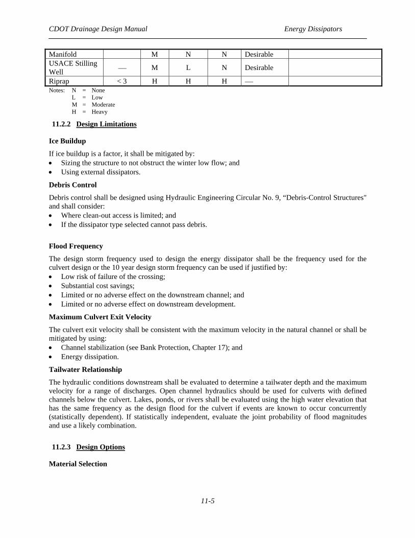
Photo 11.3

CDOT Drainage Design Manual Energy Dissipators
11-4
Internal Dissipators
Internal dissipators are used where: • The scour hole at the culvert outlet is unacceptable; • The right-of-way is limited; • Debris is not a problem; and • Moderate velocity reduction is needed.
Natural Scour Holes
Natural scour holes are used where: • Undermining of the culvert outlet will not occur or it is practicable to be checked by a cutoff wall; • The expected scour hole will not cause costly property damage; and • There is no nuisance effect.
External Dissipators
External dissipators are used where: • The outlet scour hole is not acceptable; • Moderate amount of debris is present; and • The culvert outlet velocity is moderate, and corresponding Fr < 3.
Stilling Basins
Stilling Basins are used where: • The outlet scour hole is not acceptable; • Debris is present; and • The culvert outlet velocity is high, and corresponding Fr > 3.
TABLE 11.1 Dissipator Limitations (after HEC 14) Allowable Debris
Dissipator Type Froude Number (Fr)
Silt/ Sand Boulders Floating
Tailwater (TW) Special Considerations
Free Hydraulic Jump > 1 H H H Required
CSU Rigid Boundary < 3 M L M ⎯
Tumbling Flow > 1 M L L ⎯ 4 < So < 25 Increased Resistance ⎯ M L L ⎯ Check Outlet Control HW
USBR Type II 4 to 14 M L M Required USBR Type III 4.5 to 17 M L M Required USBR Type IV 2.5 to 4.5 M L M Required SAF 1.7 to 17 M L M Required Contra Costa < 3 H M M < 0.5d Hook 1.8 to 3 H M M ⎯ USBR Type VI ⎯ M L L Desirable Q < 400 cfs V < 50 fps Forest Service ⎯ M L L Desirable D < 3 ft Drop Structure < 1 H L M Required Drop < 15 ft
CDOT Drainage Design Manual Energy Dissipators
11-5
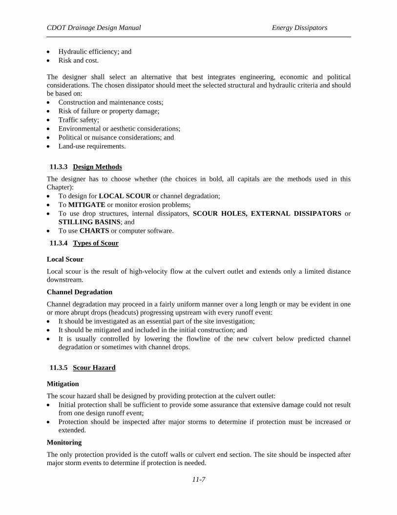
Manifold M N N Desirable USACE Stilling Well ⎯ M L N Desirable
Riprap < 3 H H H ⎯ Notes: N = None L = Low M = Moderate H = Heavy
11.2.2 Design Limitations
Ice Buildup
If ice buildup is a factor, it shall be mitigated by: • Sizing the structure to not obstruct the winter low flow; and • Using external dissipators.
Debris Control
Debris control shall be designed using Hydraulic Engineering Circular No. 9, “Debris-Control Structures" and shall consider: • Where clean-out access is limited; and • If the dissipator type selected cannot pass debris.
Flood Frequency
The design storm frequency used to design the energy dissipator shall be the frequency used for the culvert design or the 10 year design storm frequency can be used if justified by: • Low risk of failure of the crossing; • Substantial cost savings; • Limited or no adverse effect on the downstream channel; and • Limited or no adverse effect on downstream development.
Maximum Culvert Exit Velocity
The culvert exit velocity shall be consistent with the maximum velocity in the natural channel or shall be mitigated by using: • Channel stabilization (see Bank Protection, Chapter 17); and • Energy dissipation.
Tailwater Relationship
The hydraulic conditions downstream shall be evaluated to determine a tailwater depth and the maximum velocity for a range of discharges. Open channel hydraulics should be used for culverts with defined channels below the culvert. Lakes, ponds, or rivers shall be evaluated using the high water elevation that has the same frequency as the design flood for the culvert if events are known to occur concurrently (statistically dependent). If statistically independent, evaluate the joint probability of flood magnitudes and use a likely combination.
11.2.3 Design Options
Material Selection

CDOT Drainage Design Manual Energy Dissipators
11-6
The material selected for the dissipator shall be based on a comparison of the total cost over the design life of alternative materials and shall not be made using first cost as the only criteria. This comparison shall consider replacement cost and the difficulty of construction and traffic delay.
Culvert Outlet Type
In choosing a dissipator, the selected culvert end treatment has the following implications: • Culvert ends that are projecting or mitered to the fill slope offer no outlet protection; • Headwalls provide embankment stability and erosion protection. They provide protection from
buoyancy and reduce damage to the culvert; • Commercial end sections add little cost to the culvert and may require less maintenance, retard
embankment erosion and incur less damage from maintenance; • Aprons do not reduce outlet velocity; they increase the time it takes before outlet erosion undercuts
the culvert. All large pipe culverts and CBCs require as a minimum a concrete apron at the outlet. The concrete apron shall extend at least one culvert height downstream and shall have a toewall at the end of the apron. The apron and culvert outlet should be at least 6 inches below the normal streambed elevation; and
• Wingwalls are used where the side slopes of the channel are unstable, where the culvert is skewed to the normal channel flow, to redirect outlet velocity or to retain fill.
Safety Considerations
Traffic shall be protected from external energy dissipators by locating them outside the appropriate "clear zone" distance per AASHTO Roadside Design Guide or shielding them with a traffic barrier.
Weep Holes
If weep holes are used to relieve uplift pressure, they shall be designed in a manner similar to underdrain systems.
11.2.4 Related Designs
Culvert
The culvert shall be designed independent of the dissipator design (see Culverts, Chapter 9) with the exception of internal dissipators, which may require an iterative solution. The culvert design shall be completed before the outlet protection is designed and shall include computation of outlet velocity.
Downstream Channel
The downstream channel protection shall be designed concurrently with dissipator design.
11.3 DESIGN PHILOSOPHY
11.3.1 Overview
The energy dissipator design approach used in this Chapter is discussed in the following Sections.
11.3.2 Alternative Analysis
The designer shall choose alternatives that satisfy: • Topography; and • Design policies and criteria. The designer shall analyze alternatives for: • Environmental impact;
CDOT Drainage Design Manual Energy Dissipators
11-7
• Hydraulic efficiency; and • Risk and cost. The designer shall select an alternative that best integrates engineering, economic and political considerations. The chosen dissipator should meet the selected structural and hydraulic criteria and should be based on: • Construction and maintenance costs; • Risk of failure or property damage; • Traffic safety; • Environmental or aesthetic considerations; • Political or nuisance considerations; and • Land-use requirements.
11.3.3 Design Methods
The designer has to choose whether (the choices in bold, all capitals are the methods used in this Chapter): • To design for LOCAL SCOUR or channel degradation; • To MITIGATE or monitor erosion problems; • To use drop structures, internal dissipators, SCOUR HOLES, EXTERNAL DISSIPATORS or
STILLING BASINS; and • To use CHARTS or computer software.
11.3.4 Types of Scour
Local Scour
Local scour is the result of high-velocity flow at the culvert outlet and extends only a limited distance downstream.
Channel Degradation
Channel degradation may proceed in a fairly uniform manner over a long length or may be evident in one or more abrupt drops (headcuts) progressing upstream with every runoff event: • It should be investigated as an essential part of the site investigation; • It should be mitigated and included in the initial construction; and • It is usually controlled by lowering the flowline of the new culvert below predicted channel
degradation or sometimes with channel drops.
11.3.5 Scour Hazard
Mitigation
The scour hazard shall be designed by providing protection at the culvert outlet: • Initial protection shall be sufficient to provide some assurance that extensive damage could not result
from one design runoff event; • Protection should be inspected after major storms to determine if protection must be increased or
extended.
Monitoring
The only protection provided is the cutoff walls or culvert end section. The site should be inspected after major storm events to determine if protection is needed.

CDOT Drainage Design Manual Energy Dissipators
11-8
11.3.6 Dissipator Types
Scour Holes
Details of the design of scour holes area are as shown below.
Internal Dissipators
• Tumbling flow; • Increased resistance; and • Broken-back culverts. This Chapter does not include details of the design of Internal Dissipators. The designer should refer to HEC 14 if design details are needed.
External Dissipators
• USBR TYPE VI IMPACT (see HEC-14); • RIPRAP (see HEC-14); • CSU rigid boundary (see HEC 14); • Contra Costa (see HEC 14); • Hook (see HEC 14); and • Hydraulic jump (see HEC 14).
Stilling Basins
• Saint Anthony Falls (SAF) (see HEC-14); • USBR Type II (see HEC 14); • USBR Type III (see HEC 14); • USBR Type IV (see HEC 14).
Drop Structures
• See HEC 14 or Urban Drainage and Flood Control Manual.
11.3.7 Computational Methods
Charts
Charts are required for a manual solution. Charts required for the design of scour holes, riprap basin, USBR Type VI impact basin and SAF basin are included in this Chapter. Charts required for the design of other types of energy dissipators are found in HEC 14.
Computer Software
HY-8 (FHWA Culvert Analysis Software), Version 4.1 or greater contains an energy dissipator module that can be used to analyze most types of energy dissipators in HEC 14.
11.4 DESIGN EQUATIONS
11.4.1 General
An exact theoretical analysis of flow at culvert outlets is extremely complex because the following data is required:
CDOT Drainage Design Manual Energy Dissipators
11-9
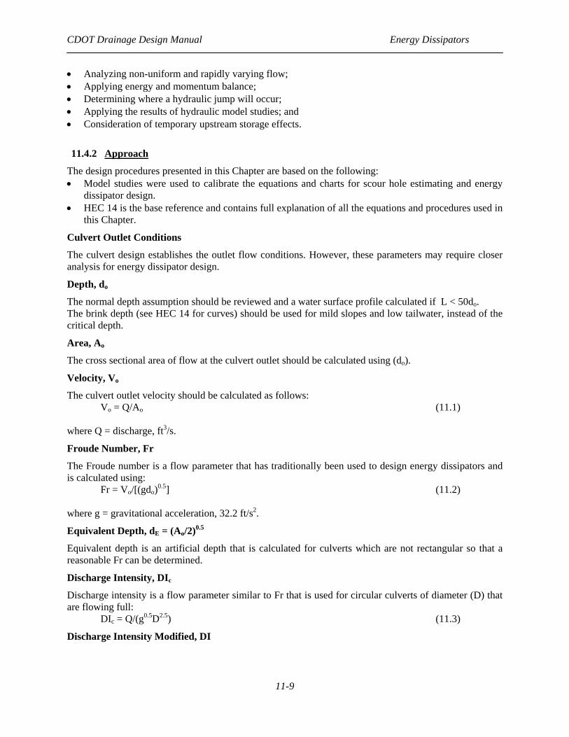
• Analyzing non-uniform and rapidly varying flow; • Applying energy and momentum balance; • Determining where a hydraulic jump will occur; • Applying the results of hydraulic model studies; and • Consideration of temporary upstream storage effects.
11.4.2 Approach
The design procedures presented in this Chapter are based on the following: • Model studies were used to calibrate the equations and charts for scour hole estimating and energy
dissipator design. • HEC 14 is the base reference and contains full explanation of all the equations and procedures used in
this Chapter.
Culvert Outlet Conditions
The culvert design establishes the outlet flow conditions. However, these parameters may require closer analysis for energy dissipator design.
Depth, do
The normal depth assumption should be reviewed and a water surface profile calculated if L < 50do. The brink depth (see HEC 14 for curves) should be used for mild slopes and low tailwater, instead of the critical depth.
Area, Ao
The cross sectional area of flow at the culvert outlet should be calculated using (do).
Velocity, Vo
The culvert outlet velocity should be calculated as follows: Vo = Q/Ao (11.1) where Q = discharge, ft3/s.
Froude Number, Fr
The Froude number is a flow parameter that has traditionally been used to design energy dissipators and is calculated using: Fr = Vo/[(gdo)0.5] (11.2) where g = gravitational acceleration, 32.2 ft/s2.
Equivalent Depth, dE = (Ao/2)0.5
Equivalent depth is an artificial depth that is calculated for culverts which are not rectangular so that a reasonable Fr can be determined.
Discharge Intensity, DIc
Discharge intensity is a flow parameter similar to Fr that is used for circular culverts of diameter (D) that are flowing full: DIc = Q/(g0.5D2.5) (11.3)
Discharge Intensity Modified, DI
CDOT Drainage Design Manual Energy Dissipators
11-10
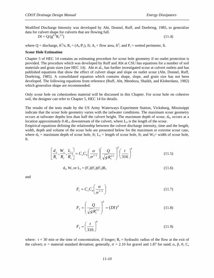
Modified Discharge Intensity was developed by Abt, Donnel, Ruff, and Doehring, 1985, to generalize data for culvert shape for culverts that are flowing full. DI = Q/(g0.5Rc
2.5) (11.4) where Q = discharge, ft3/s; Rc = (Ac/Pc), ft; Ac = flow area, ft2; and Pc = wetted perimeter, ft.
Scour Hole Estimation
Chapter 5 of HEC 14 contains an estimating procedure for scour hole geometry if no outlet protection is provided. The procedure which was developed by Ruff and Abt at CSU has equations for a number of soil materials and grain sizes (see HEC 14). Abt et al., has further investigated scour at culvert outlets and has published equations that show the effect of culvert shape and slope on outlet scour (Abt, Donnel, Ruff, Doehring, 1985). A consolidated equation which contains shape, slope, and grain size has not been developed. The following equations from reference (Ruff, Abt, Mendoza, Shaikh, and Kloberdanz, 1982) which generalize shape are recommended: Only scour hole on cohesionless material will be discussed in this Chapter. For scour hole on cohesive soil, the designer can refer to Chapter 5, HEC 14 for details. The results of the tests made by the US Army Waterways Experiment Station, Vicksburg, Mississippi indicate that the scour hole geometry varies with the tailwater conditions. The maximum scour geometry occurs at tailwater depths less than half the culvert height. The maximum depth of scour, dS, occurs at a location approximately 0.4LS downstream of the culvert, where LS is the length of the scour. Empirical equations defining the relationship between the culvert discharge intensity, time and the length, width, depth and volume of the scour hole are presented below for the maximum or extreme scour case, where dS = maximum depth of scour hole, ft; LS = length of scour hole, ft; and WS= width of scour hole, ft.
θβ
σα
⎟⎠⎞
⎜⎝⎛
⎟⎟⎠
⎞⎜⎜⎝
⎛⎟⎠⎞
⎜⎝⎛=⎥
⎦
⎤⎢⎣
⎡316
,,5.23/1
tRg
QCCRL
RW
Rd
chs
c
s
c
s
c
s (11.5)
ds, Ws or Ls = (F1)(F2)(F3)Rc (11.6)
and
⎟⎠⎞
⎜⎝⎛= 3/11 σα
hsCCF (11.7)
β
β
)(5.22 DI
RgQF
c
=⎟⎟⎠
⎞⎜⎜⎝
⎛= (11.8)
θ
⎟⎠⎞
⎜⎝⎛=
3163tF (11.9)
where: t = 30 min or the time of concentration, if longer; Rc = hydraulic radius of the flow at the exit of the culvert; σ = material standard deviation; generally, σ = 2.10 for gravel and 1.87 for sand; α, β, θ, Cs
CDOT Drainage Design Manual Energy Dissipators
11-11
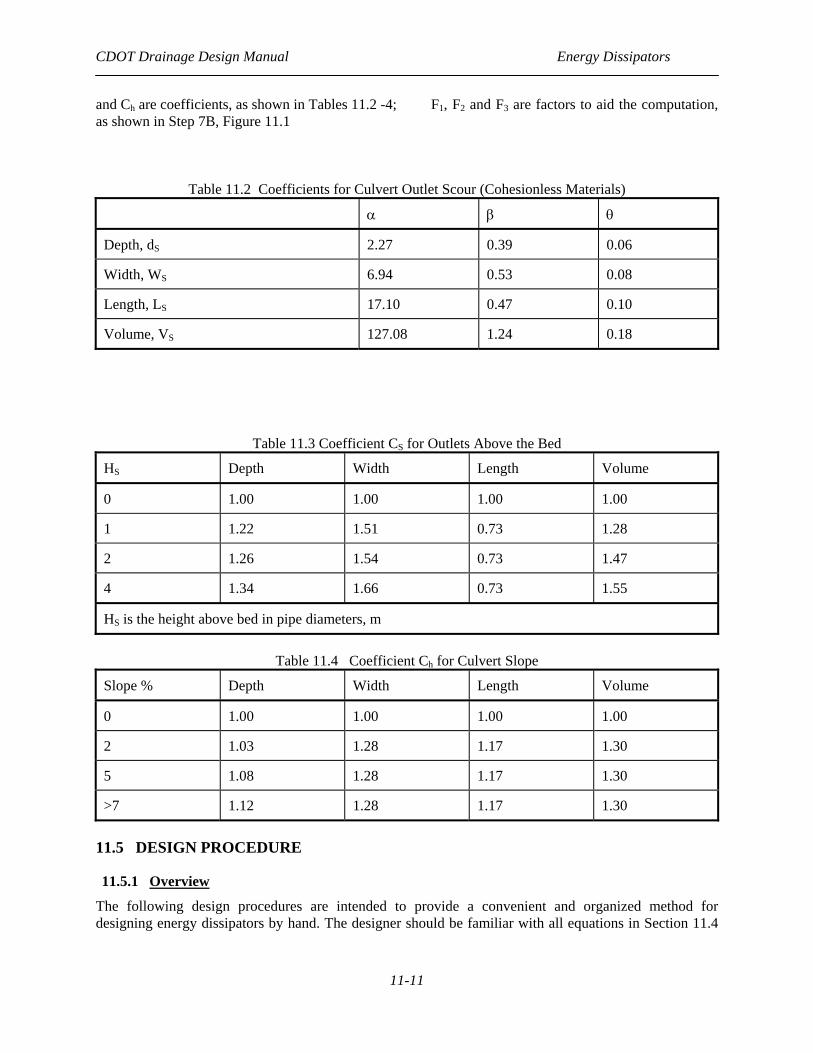
and Ch are coefficients, as shown in Tables 11.2 -4; F1, F2 and F3 are factors to aid the computation, as shown in Step 7B, Figure 11.1
Table 11.2 Coefficients for Culvert Outlet Scour (Cohesionless Materials)
α β θ
Depth, dS 2.27 0.39 0.06
Width, WS 6.94 0.53 0.08
Length, LS 17.10 0.47 0.10
Volume, VS 127.08 1.24 0.18
Table 11.3 Coefficient CS for Outlets Above the Bed
HS Depth Width Length Volume
0 1.00 1.00 1.00 1.00
1 1.22 1.51 0.73 1.28
2 1.26 1.54 0.73 1.47
4 1.34 1.66 0.73 1.55
HS is the height above bed in pipe diameters, m
Table 11.4 Coefficient Ch for Culvert Slope
Slope % Depth Width Length Volume
0 1.00 1.00 1.00 1.00
2 1.03 1.28 1.17 1.30
5 1.08 1.28 1.17 1.30
>7 1.12 1.28 1.17 1.30
11.5 DESIGN PROCEDURE
11.5.1 Overview
The following design procedures are intended to provide a convenient and organized method for designing energy dissipators by hand. The designer should be familiar with all equations in Section 11.4

CDOT Drainage Design Manual Energy Dissipators
11-12
before using these procedures. In addition, application of the following design method without an understanding of hydraulics can result in an inadequate, unsafe or costly structure: Step 1 Assemble Site Data And Project File a. See culvert design file for site survey. b. Review Section 11.2.2 for applicable criteria. Step 2 Determine Hydrology See culvert design file. Step 3 Select Design Q a. See Section 11.2.3 “Design Limitations.” b. See culvert design file.
c. Select flood frequency. d. Determine Q from frequency plot (Step 2). Step 4 Review Downstream Channel a. See culvert design file. b. Determine channel slope, cross section, normal depth and velocity.
c. Check bed and bank material stability. Step 5 Review Culvert Design
See culvert design file and obtain design discharge, outlet flow conditions (velocity and depth), culvert type (size, shape and roughness), culvert slope and performance curve.
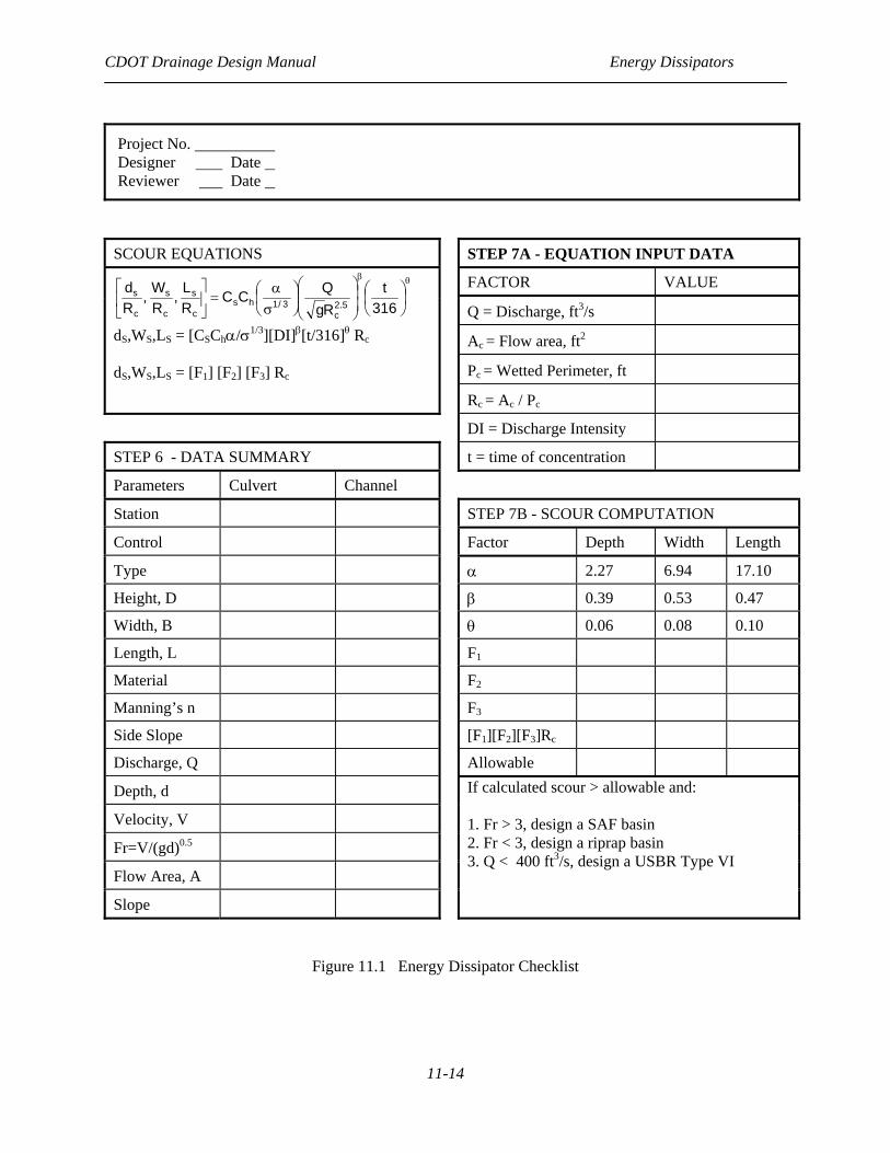
Step 6 Summarize Data On Design Form.
a. Use Figure 11-1 “Energy Dissipator Checklist.” b. Enter data from Steps 1-5 into Figure 11-1.
Step 7 Estimate Scour Hole Size. a. Enter input for scour equation on Figure 11-1.
b. Calculate dS, WS, LS , using Equation 11.5 or 11.6 Step 8 Determine Need For Dissipator. An energy dissipator is needed if:
a. the estimated scour hole dimensions that exceed the allowable right-of-way, undermines the culvert cutoff wall or presents a safety or aesthetic problem;
b. downstream property is threatened; or c. Vo is much greater than Vd.
Step 9 Select Design Alternative. a. See Section 11.2.4 “Design Options.”
b. Calculate Froude number, Fr. c. Choose energy dissipator types:
-if Fr > 3, design a SAF stilling basin; -if Fr < 3 design a riprap basin; -if Q < 400 cfs and little debris is expected, design a USBR Type VI for each barrel. If these are not acceptable or economical, try other dissipators in HEC 14.

CDOT Drainage Design Manual Energy Dissipators
11-13
Step 10 Design Dissipators Use the design procedures and charts in Hec 14. Step 11 Design Riprap Transition a. Most dissipators require some protection adjacent to the basin exit.
b. The length of protection can be judged based on the difference between Vo and Vd. The riprap should be designed using Chapter 17 “Bank Protection” and HEC-11.
Step 12 Review Results
a. If downstream channel conditions (velocity, depth and stability) are exceeded, -design riprap for channel, Step 4; or -select another dissipator, Step 9.
b. If preferred energy dissipator affects culvert hydraulics, return to Step 5 and calculate culvert performance.
c. If debris-control structures are required upstream, consult HEC 9. Step 13 Documentation a. See Chapter 4.
b. Include computations in culvert report or file.
CDOT Drainage Design Manual Energy Dissipators
11-14
Project No. Designer Date Reviewer Date
SCOUR EQUATIONS STEP 7A - EQUATION INPUT DATA FACTOR VALUE Q = Discharge, ft3/s
Ac = Flow area, ft2
Pc = Wetted Perimeter, ft
θβ
⎟⎠⎞
⎜⎝⎛
⎟⎟⎠
⎞⎜⎜⎝
⎛⎟⎠⎞
⎜⎝⎛σα
=⎥⎦
⎤⎢⎣
⎡316
tRgQCC
RL,
RW,
Rd
5.2c
3/1hsc
s
c
s
c
s
dS,WS,LS = [CSChα/σ1/3][DI]β[t/316]θ Rc dS,WS,LS = [F1] [F2] [F3] Rc
Rc = Ac / Pc
DI = Discharge Intensity
STEP 6 - DATA SUMMARY t = time of concentration
Parameters Culvert Channel
Station STEP 7B - SCOUR COMPUTATION
Control Factor Depth Width Length
Type α 2.27 6.94 17.10
Height, D β 0.39 0.53 0.47
Width, B θ 0.06 0.08 0.10
Length, L F1
Material F2
Manning’s n F3
Side Slope [F1][F2][F3]Rc
Discharge, Q Allowable
Depth, d
Velocity, V
Fr=V/(gd)0.5
Flow Area, A
Slope
If calculated scour > allowable and: 1. Fr > 3, design a SAF basin 2. Fr < 3, design a riprap basin 3. Q < 400 ft3/s, design a USBR Type VI
Figure 11.1 Energy Dissipator Checklist
CDOT Drainage Design Manual Energy Dissipators
11-15
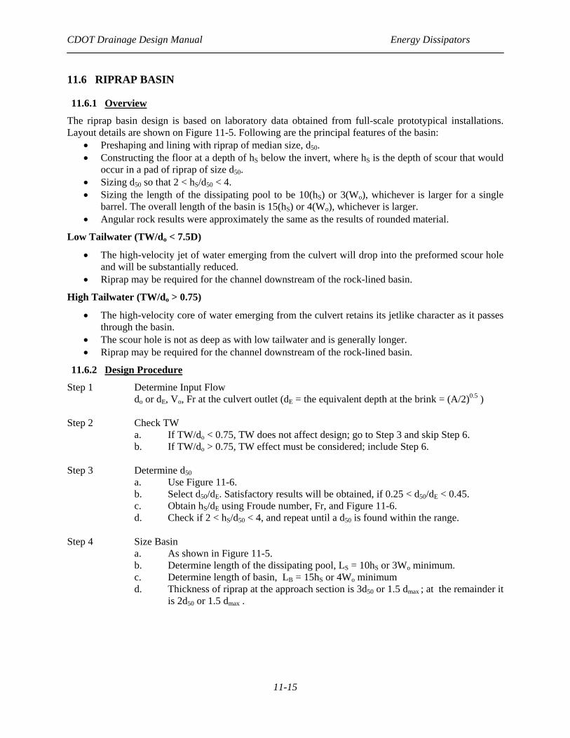
11.6 RIPRAP BASIN
11.6.1 Overview
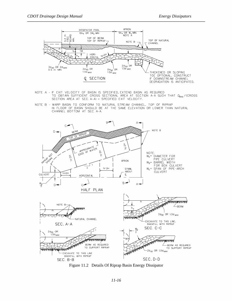
The riprap basin design is based on laboratory data obtained from full-scale prototypical installations. Layout details are shown on Figure 11-5. Following are the principal features of the basin:
• Preshaping and lining with riprap of median size, d50. • Constructing the floor at a depth of hS below the invert, where hS is the depth of scour that would
occur in a pad of riprap of size d50. • Sizing d50 so that 2 < hS/d50 < 4. • Sizing the length of the dissipating pool to be 10(hS) or 3(Wo), whichever is larger for a single
barrel. The overall length of the basin is 15(hS) or 4(Wo), whichever is larger. • Angular rock results were approximately the same as the results of rounded material.
Low Tailwater (TW/do < 7.5D)
• The high-velocity jet of water emerging from the culvert will drop into the preformed scour hole and will be substantially reduced.
• Riprap may be required for the channel downstream of the rock-lined basin.
High Tailwater (TW/do > 0.75)
• The high-velocity core of water emerging from the culvert retains its jetlike character as it passes through the basin.
• The scour hole is not as deep as with low tailwater and is generally longer. • Riprap may be required for the channel downstream of the rock-lined basin.
11.6.2 Design Procedure
Step 1 Determine Input Flow do or dE, Vo, Fr at the culvert outlet (dE = the equivalent depth at the brink = (A/2)0.5 )
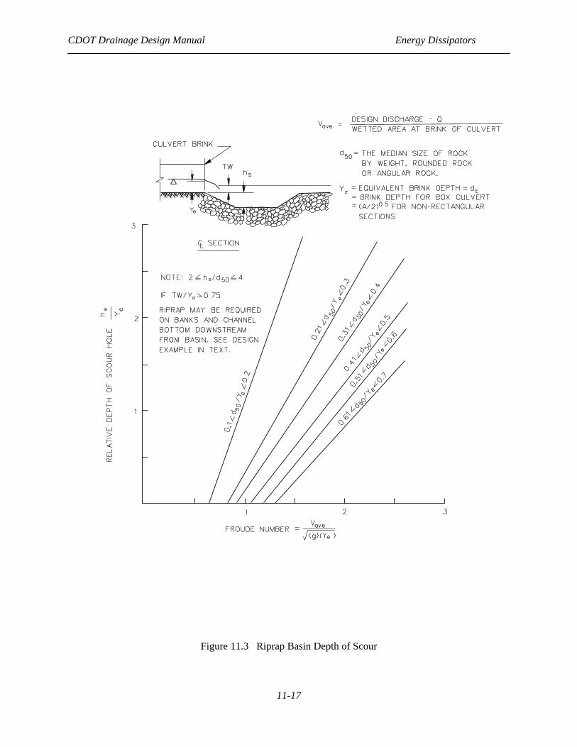
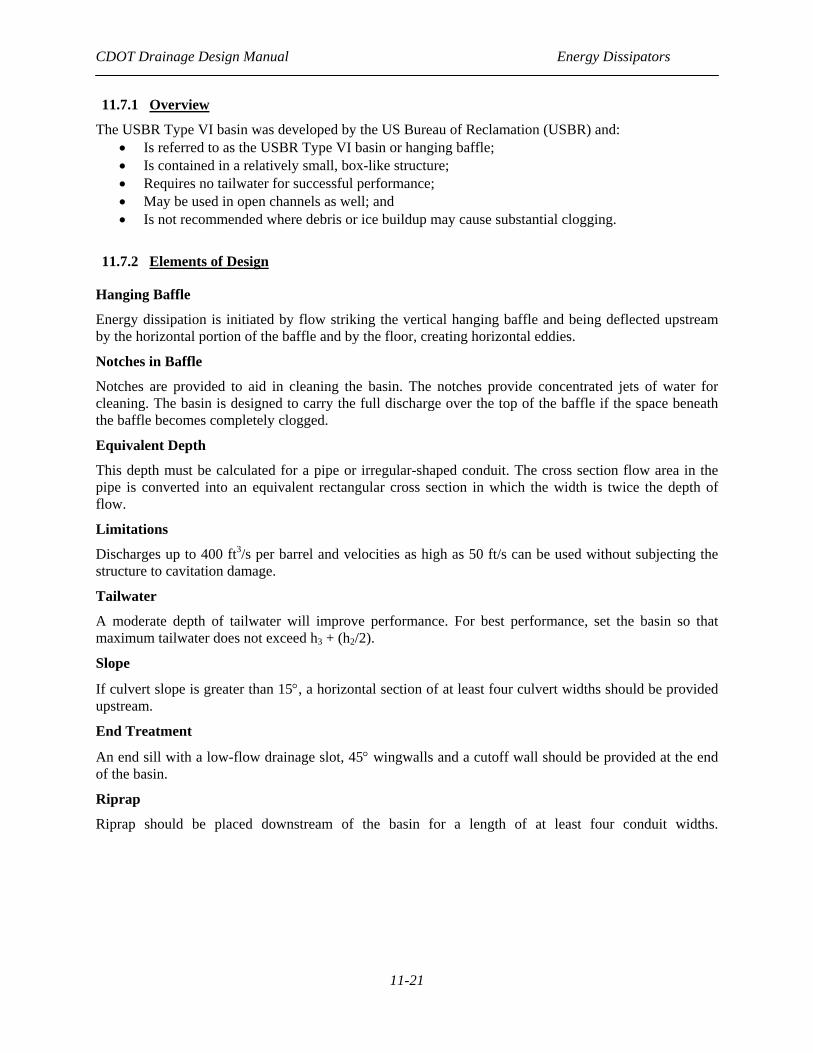
Step 2 Check TW a. If TW/do < 0.75, TW does not affect design; go to Step 3 and skip Step 6. b. If TW/do > 0.75, TW effect must be considered; include Step 6. Step 3 Determine d50 a. Use Figure 11-6. b. Select d50/dE. Satisfactory results will be obtained, if 0.25 < d50/dE < 0.45. c. Obtain hS/dE using Froude number, Fr, and Figure 11-6. d. Check if 2 < hS/d50 < 4, and repeat until a d50 is found within the range. Step 4 Size Basin a. As shown in Figure 11-5. b. Determine length of the dissipating pool, LS = 10hS or 3Wo minimum. c. Determine length of basin, LB = 15hS or 4Wo minimum
d. Thickness of riprap at the approach section is 3d50 or 1.5 dmax ; at the remainder it is 2d50 or 1.5 dmax .
CDOT Drainage Design Manual Energy Dissipators
11-16
Figure 11.2 Details Of Riprap Basin Energy Dissipator
CDOT Drainage Design Manual Energy Dissipators
11-17
Figure 11.3 Riprap Basin Depth of Scour
CDOT Drainage Design Manual Energy Dissipators
11-18
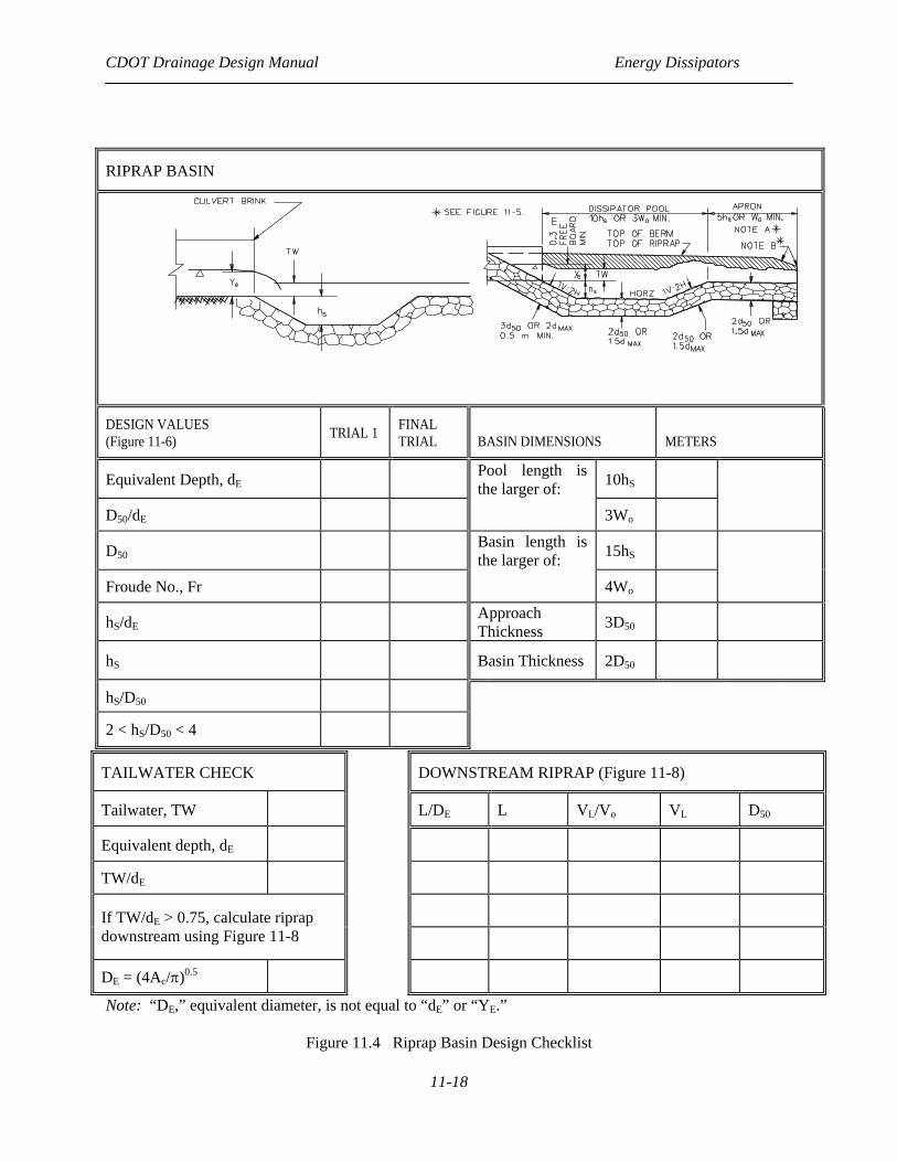
TAILWATER CHECK DOWNSTREAM RIPRAP (Figure 11-8)
Tailwater, TW L/DE L VL/Vo VL D50
Equivalent depth, dE
TW/dE
If TW/dE > 0.75, calculate riprap downstream using Figure 11-8
DE = (4Ac/π)0.5
Note: “DE,” equivalent diameter, is not equal to “dE” or “YE.”
Figure 11.4 Riprap Basin Design Checklist
RIPRAP BASIN
DESIGN VALUES (Figure 11-6) TRIAL 1 FINAL
TRIAL BASIN DIMENSIONS
METERS
Equivalent Depth, dE Pool length is the larger of: 10hS
D50/dE 3Wo
D50 Basin length is the larger of: 15hS
Froude No., Fr 4Wo
hS/dE Approach Thickness 3D50
hS Basin Thickness 2D50
hS/D50
2 < hS/D50 < 4

CDOT Drainage Design Manual Energy Dissipators
11-19
Step 5 Determine VB a. Basin exit depth, dB = critical depth at basin exit. b. Basin exit velocity, VB = Q/(WB)(dB).
c. Compare VB with the average normal flow velocity in the natural channel, Vd. The goal of this comparison is that VB will be the same or lower than the natural channel velocity.
d. If TW/do ≤ 0.75, go to Step 7. Step 6 High Tailwater Design a. Design a basin for low tailwater conditions, Steps 1 through 5. b. Compute equivalent circular diameter DE for brink area from: A = πD/4 = do(Wo)
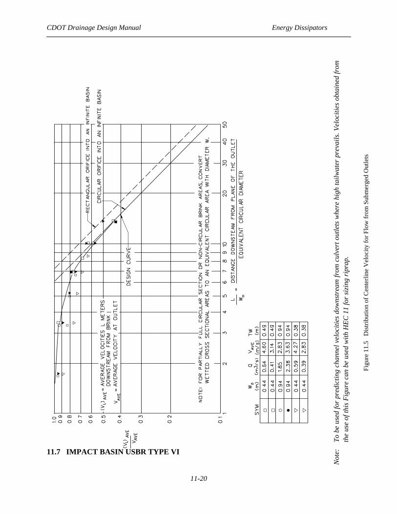
c. Estimate centerline velocity at a series of downstream cross sections using Figure 11.5.
d. Size riprap using HEC 11 or the Channels Chapter. Step 7 Design Filter a. Unless the streambed material is sufficiently well graded. b. Follow instructions in Section 4.4, HEC 11.
CDOT Drainage Design Manual Energy Dissipators
11-20
11.7 IMPACT BASIN USBR TYPE VI
Not
e:
To b
e us
ed fo
r pr
edic
ting
chan
nel v
eloc
ities
dow
nstr
eam
from
cul
vert
out
lets
whe
re h
igh
tailw
ater
pre
vails
. Vel
ociti
es o
btai
ned
from
th
e us
e of
this
Fig
ure
can
be u
sed
with
HEC
11
for s
izin
g ri
prap
.
Figu
re 1
1.5
Dis
tribu
tion
of C
ente
rline
Vel
ocity
for F
low
from
Sub
mer
ged
Out
lets
CDOT Drainage Design Manual Energy Dissipators
11-21
11.7.1 Overview
The USBR Type VI basin was developed by the US Bureau of Reclamation (USBR) and: • Is referred to as the USBR Type VI basin or hanging baffle; • Is contained in a relatively small, box-like structure; • Requires no tailwater for successful performance; • May be used in open channels as well; and • Is not recommended where debris or ice buildup may cause substantial clogging.
11.7.2 Elements of Design
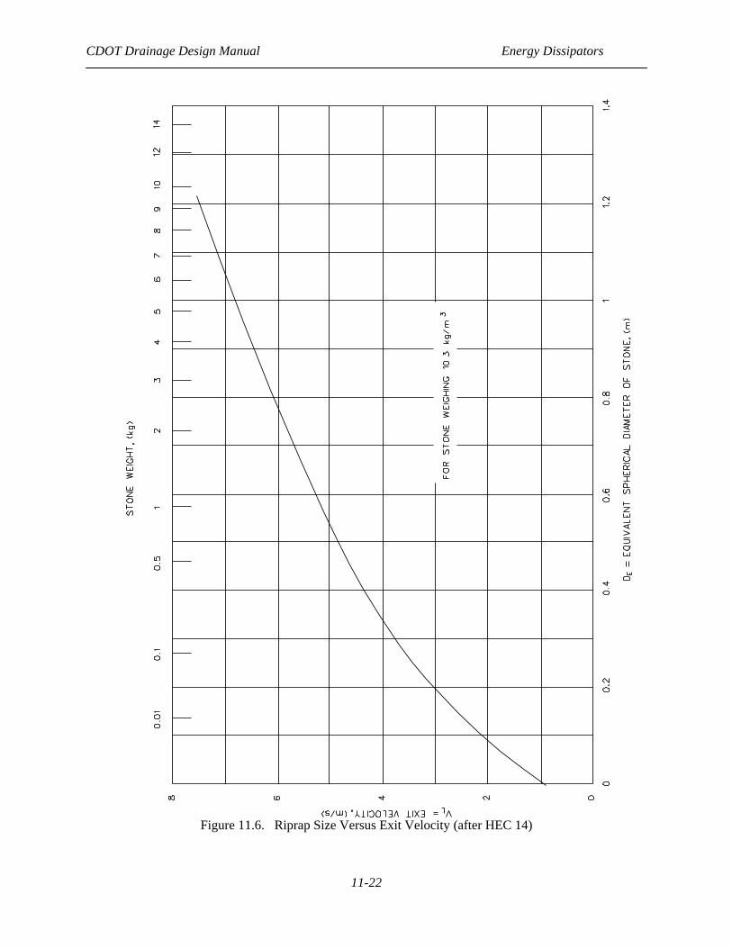
Hanging Baffle
Energy dissipation is initiated by flow striking the vertical hanging baffle and being deflected upstream by the horizontal portion of the baffle and by the floor, creating horizontal eddies.
Notches in Baffle
Notches are provided to aid in cleaning the basin. The notches provide concentrated jets of water for cleaning. The basin is designed to carry the full discharge over the top of the baffle if the space beneath the baffle becomes completely clogged.
Equivalent Depth
This depth must be calculated for a pipe or irregular-shaped conduit. The cross section flow area in the pipe is converted into an equivalent rectangular cross section in which the width is twice the depth of flow.
Limitations
Discharges up to 400 ft3/s per barrel and velocities as high as 50 ft/s can be used without subjecting the structure to cavitation damage.
Tailwater
A moderate depth of tailwater will improve performance. For best performance, set the basin so that maximum tailwater does not exceed h3 + (h2/2).
Slope
If culvert slope is greater than 15°, a horizontal section of at least four culvert widths should be provided upstream.
End Treatment
An end sill with a low-flow drainage slot, 45° wingwalls and a cutoff wall should be provided at the end of the basin.
Riprap
Riprap should be placed downstream of the basin for a length of at least four conduit widths.
CDOT Drainage Design Manual Energy Dissipators
11-22
Figure 11.6. Riprap Size Versus Exit Velocity (after HEC 14)
CDOT Drainage Design Manual Energy Dissipators
11-23
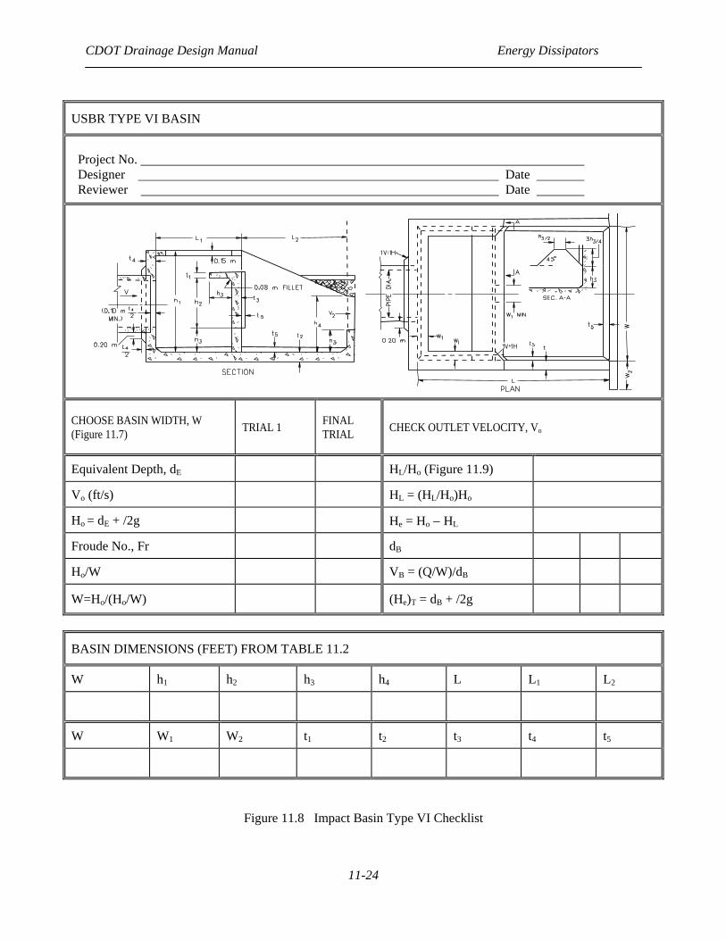
Figure 11.7 USBR Type VI (Impact) Dissipator
CDOT Drainage Design Manual Energy Dissipators
11-24
USBR TYPE VI BASIN
Project No. Designer Date Reviewer Date
CHOOSE BASIN WIDTH, W (Figure 11.7) TRIAL 1 FINAL
TRIAL CHECK OUTLET VELOCITY, Vo
Equivalent Depth, dE HL/Ho (Figure 11.9)
Vo (ft/s) HL = (HL/Ho)Ho
Ho = dE + /2g He = Ho − HL
Froude No., Fr dB
Ho/W VB = (Q/W)/dB
W=Ho/(Ho/W) (He)T = dB + /2g
BASIN DIMENSIONS (FEET) FROM TABLE 11.2
W h1 h2 h3 h4 L L1 L2
W W1 W2 t1 t2 t3 t4 t5
Figure 11.8 Impact Basin Type VI Checklist
CDOT Drainage Design Manual Energy Dissipators
11-25
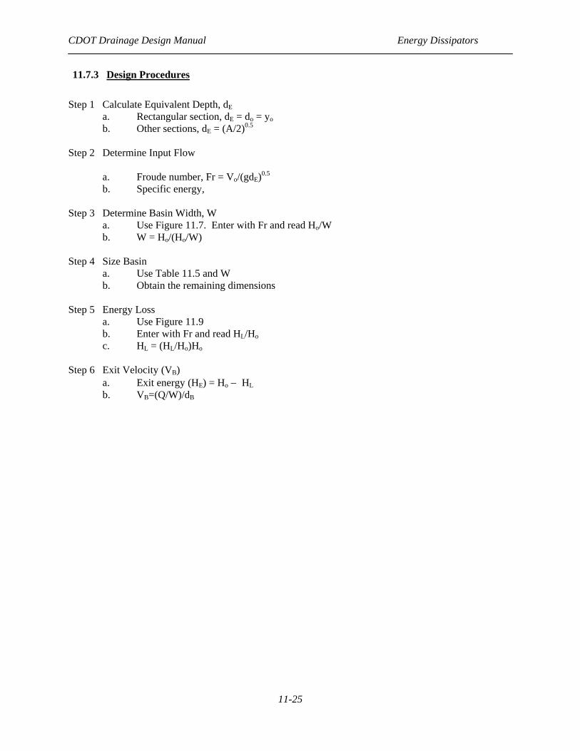
11.7.3 Design Procedures
Step 1 Calculate Equivalent Depth, dE a. Rectangular section, dE = do = yo b. Other sections, dE = (A/2)0.5 Step 2 Determine Input Flow a. Froude number, Fr = Vo/(gdE)0.5
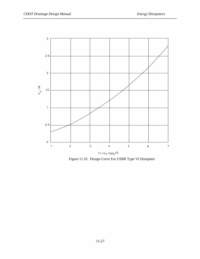
b. Specific energy, Step 3 Determine Basin Width, W a. Use Figure 11.7. Enter with Fr and read Ho/W
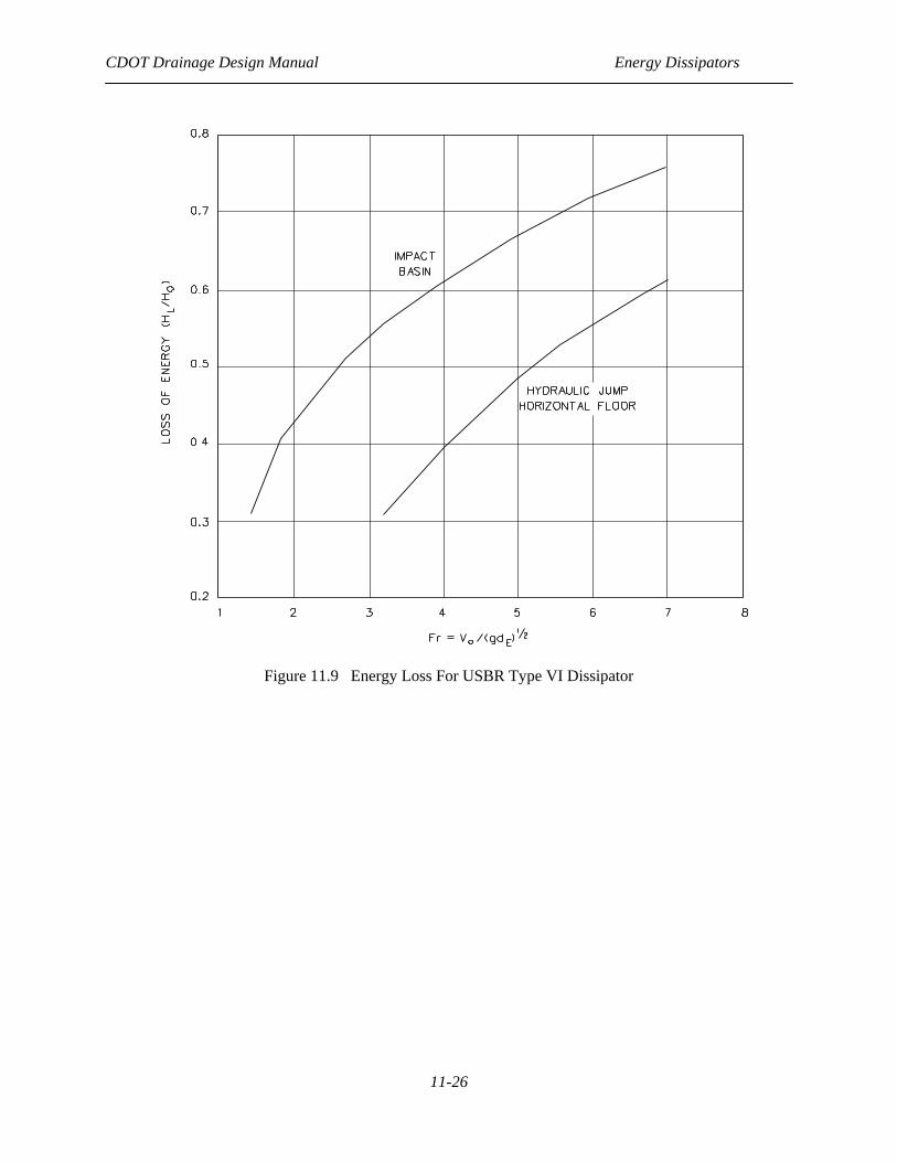
b. W = Ho/(Ho/W) Step 4 Size Basin a. Use Table 11.5 and W b. Obtain the remaining dimensions Step 5 Energy Loss a. Use Figure 11.9 b. Enter with Fr and read HL/Ho c. HL = (HL/Ho)Ho Step 6 Exit Velocity (VB) a. Exit energy (HE) = Ho − HL
b. VB=(Q/W)/dB
CDOT Drainage Design Manual Energy Dissipators
11-26
Figure 11.9 Energy Loss For USBR Type VI Dissipator
CDOT Drainage Design Manual Energy Dissipators
11-27
Figure 11.10 Design Curve For USBR Type VI Dissipator
CDOT Drainage Design Manual Energy Dissipators
11-28
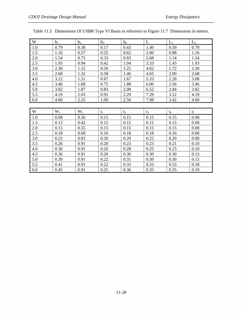
Table 11.5 Dimensions Of USBR Type VI Basin in reference to Figure 11.7 Dimensions in meters.
W h1 h2 h3 h4 L L1 L2 1.0 0.79 0.38 0.17 0.43 1.40 0.59 0.79 1.5 1.16 0.57 0.25 0.62 2.00 0.88 1.16 2.0 1.54 0.75 0.33 0.83 2.68 1.14 1.54 2.5 1.93 0.94 0.42 1.04 3.33 1.43 1.93 3.0 2.30 1.12 0.50 1.25 4.02 1.72 2.30 3.5 2.68 1.32 0.58 1.46 4.65 2.00 2.68 4.0 3.12 1.51 0.67 1.67 5.33 2.28 3.08 4.5 3.46 1.68 0.75 1.88 6.00 2.56 3.46 5.0 3.82 1.87 0.83 2.08 6.52 2.84 3.82 5.5 4.19 2.03 0.91 2.29 7.29 3.12 4.19 6.0 4.60 2.25 1.00 2.50 7.98 3.42 4.60
W W1 W2 t1 t2 t3 t4 t5
1.0 0.08 0.26 0.15 0.15 0.15 0.15 0.08 1.5 0.13 0.42 0.15 0.15 0.15 0.15 0.08 2.0 0.15 0.55 0.15 0.15 0.15 0.15 0.08 2.5 0.18 0.68 0.16 0.18 0.18 0.16 0.08 3.0 0.22 0.83 0.20 0.20 0.22 0.20 0.08 3.5 0.26 0.91 0.20 0.23 0.23 0.21 0.10 4.0 0.30 0.91 0.20 0.28 0.25 0.25 0.10 4.5 0.36 0.91 0.20 0.30 0.30 0.30 0.13 5.0 0.39 0.91 0.22 0.31 0.30 0.30 0.15 5.5 0.41 0.91 0.22 0.33 0.33 0.33 0.18 6.0 0.45 0.91 0.25 0.36 0.35 0.35 0.19
CDOT Drainage Design Manual Energy Dissipators
11-29
REFERENCES
AASHTO, “Roadside Design Guide, Task Force on Roadside Safety,”, 2002.
Abt, S.R., Donnell, C.A., Ruff, J.F. and Doehring, F.K., “Culvert Shape and Slope Effects on Outlet Scour,” Transportation Research Record 1017, 1985.
American Society of Civil Engineers, “Hydraulic Design of Stilling Basins,” Journal of the Hydraulics Division, Paper 1406, October 1957.
Blaiswell, F.W., SAF Stilling Basin, US Government Printing Office, 1959.
Bureau of Reclamation, “Hydraulic Design of Stilling Basins and Energy Dissipators,” Engineering Monograph No. 25, third printing, 1974.
Donnelly, Charles A., and Blaisdell, Fred W., “Straight Drop Spillway Stilling Basin,” University of Minnesota, St. Anthony Falls Hydraulic Laboratory, Technical Paper 15, Series B, November 1954.
Federal Highway Administration, “Bridge Scour and Stream Instability Countermeasures,”, Hydraulic Engineering Circular No. 23, FHWA-HI-97-030, Washington, DC, 1997.
Federal Highway Administration, “Debris-Control Structures,” Hydraulic Engineering Circular No. 9, FHWA-EPD-86-106, Washington, DC, 1971.
Federal Highway Administration, “Design of Riprap Revetment,” Hydraulic Engineering Circular No. 11, FHWA-IP-89-016, Washington, DC, 1989.
Federal Highway Administration, HYDRAIN, “Drainage Design Computer System,” (Version 6.1), FHWA-IF-99-008, 1999.
Federal Highway Administration, “Hydraulic Design of Energy Dissipators for Culverts and Channels,”, Hydraulic Engineering Circular No. 14, Chapter 5, FHWA-EPD-86-110, 1983, Revised 1995.
Federal Highway Administration, “Hydraulics Library,” CDROM, FHWA-IF-00-022, 2001.
Federal Highway Administration, “Internal Energy Dissipators,” FHWA-OH-84-007, 1984.
Federal Highway Administration, “River Engineering for Highway Encroachments - Highways in the River Environment,” Hydraulic Design Series No. 6, FHWA-NHI-01-004, Washington, DC, 2001.
Pemberton, E.L. and Lara, J.M., “Computing Degradation and Local Scour,” Technical Guidelines for Bureau of Reclamation, Engineering Research Center, Denver, CO, January, 1984.
Peterka, A.J., “Hydraulic Design of Stilling Basins and Energy Dissipators,” Engineering Monograph No. 25, US Bureau of Reclamation, Division of Research, Denver, CO, 1964.
Ruff, J.F., Abt, S.R., Mendosa, C., Shaikh, A. and Kloberdanz, R., “Scour at Culvert Outlets in Mixed Bed Materials,” FHWA-RD-82-011, September 1982.

CDOT Drainage Design Manual Energy Dissipators
11-30
Stevens, M.A. and Simons, D.B., “Experimental Programs and Basic Data for Studies of Scour in Riprap at Culvert Outfalls,” Colorado State University, CER 70-7-MAS-DBS-57, 1971.
US Army Corps of Engineers, “The Streambank Erosion Control Evaluation and Demonstration Act of 1974,” Final Report to Congress, Executive Summary and Conclusions, 1981.
Related Documents