COMMITTEE CT/2 ATTENTION DR 99047 DRAFT AUSTRALIAN STANDARD FOR COMMENT LIABLE TO ALTERATION— DO NOT USE AS A STANDARD DATE OF ISSUE: 1 FEBRUARY 1999 CLOSING DATE FOR COMMENT: 31 MARCH 1999 Digital television—Terrestrial broadcasting Part 1: Characteristics of digital terrestrial television transmissions PRICE: C COPYRIGHT

Welcome message from author
This document is posted to help you gain knowledge. Please leave a comment to let me know what you think about it! Share it to your friends and learn new things together.
Transcript

COMMITTEE CT/2 ATTENTION
DR 99047
DRAFTAUSTRALIANSTANDARD FOR COMMENTLIABLE TO ALTERATION—DO NOT USE AS A STANDARD
DATE OF ISSUE: 1 FEBRUARY 1999
CLOSING DATEFOR COMMENT: 31 MARCH 1999
Digital television—Terrestrial broadcastingPart 1: Characteristics of digital terrestrial televisiontransmissions
PRICE: C
COPYRIGHT

DRAFT AUSTRALIAN STANDARD FOR COMMENT
The committee responsible for the issue of this draft comprised representatives of organizations interested in the subject matter ofthe proposed Standard. These organizations are listed on the inside back cover.
Would you please examine this proposal and draw attention to any changes which in your opinion are necessary or desirable. Thecoordination of the requirements of this draft with those of any related Standards is of particular importance and you are invited topoint out any areas where this may be necessary.
Comment should be classified into two categories: general comment and specific comment. It will assist the committee if yourcomment is presented in the form of specific recommendations for improvements of the draft Standard (e.g. specific amendments toa particular Clause). Each recommendation should be accompanied with concise reasons in support of the changes.
It would be further appreciated if you could either type or neatly print your comments in black ink on the form attached.
Standards Australia will arrange for any comment received by the closing date to be considered by the drafting committee prior to thepublication of the Standard in its final form. Comment received is not normally acknowledged because of the volume involved.
If you do not consider any alterations are necessary and find the draft generally acceptable, your advice to this effect would also beappreciated.
Your comments should be submitted by the date indicated on the front cover of this draft Standard to the Head Office of StandardsAustralia. They should be marked to the attention of the officer indicated on the top left corner of the form. We ask that commentssent by fax be confirmed by mail.
If you know of other persons or organizations who may wish to comment on this draft Standard, could you please advise them of itsavailability. Further copies of the draft are available from the Customer Service Centre listed below.
Peter N WalshGENERAL MANAGERSTANDARDIZATION POLICY AND DEVELOPMENT
Customer Service Centre Sydney Information Centre
Telephone (02) 9746 4748Australian Sales 1300 65 46 46International Services 1300 65 46 46 FacsimileUpdate Services 1300 65 46 46 (02) 9746 4765
Facsimile [email protected] Sales 1300 65 49 49
E-Mail [email protected] Telephone
Internet Address Facsimile24 hour Internet advice available at (02) 9746 4123www.standards.com.au
Administration and Head Office:Seminar Services:1 The Crescent
Homebush 2140 Northern Territory Agency:
PO Box 1055Strathfield NSW 2135
Telephone: (02) 9746 4700Fax: (02) 9746 8450
Telephone
E-Mail Address
Technical Advisory Services:
(02) 9746 4732
E-Mail [email protected]
Telephone(02) 9746 4784
Facsimile(02) 9746 2950
E-Mail [email protected]
Branches at:Newcastle:475 Hunter StreetNewcastle 2300
Queensland:232 St Pauls TerraceFortitude Valley 4006
Tasmania:237 Elizabeth StreetNorth Hobart 7000
Victoria:19–25 Raglan StreetSouth Melbourne 3205
Western Australia:1274 Hay StreetWest Perth 6005
South Australia:63 Greenhill RoadWayville 5034
Territory Construction Association191 Stuart HighwayParap 0820
Australian Capital Territory:Shop 5, Gallery LevelThe Boulevarde, City WalkCanberra 2601
RECOMMENDED CHANGES TO DRAFT AUSTRALIAN STANDARD

TO: PETER O'NEILL From (Name and Address)Standards AustraliaPO Box 1055STRATHFIELD NSW 2135FAX NO: (02) 9746 8450peter.o'[email protected]
DR 99047 Committee: CT/2 Closing Date of Comment31 MARCH 1999
Title:
Digital television - Terrestrial broadcastingPart 1: Characteristics of digital terrestrial television transmissions
1 GENERAL COMMENT (Attach if space insufficient, please type)
2 SPECIFIC COMMENT (Please type)
Clause/ Page Para- Line Recommended Changes and ReasonFigure/ (Exact wording of recommended changes should be given)Table
No graph No

2 SPECIFIC COMMENT (Please type)
Clause/ Page Para- Line Recommended Changes and ReasonFigure/ (Exact wording of recommended changes should be given)Table
No graph No
DRAFT
ONLY 2 DRAFT ONLY
17070.CDRR.DOC 21/01/99
PREFACE
This Standard was prepared by the Standards Australia Committee CT/2, Broadcasting andRelated Services.
The objective of this Standard is to provide television receiver manufacturers andbroadcasters with the technical specification for the Australian digital terrestrial televisiontransmission system in order to achieve interoperability in DTTB transmission andreception.
This Standard, Digital television—Terrestrial broadcasting: Characteristics of digitalterrestrial television transmission, is Part 1 of a series on the subject of digital broadcasting.It is important to note that some sections of this Part are yet to be completed, asindicated in the text. Other parts still in development will address digital televisionplanning, digital television receivers, digital sound transmissions and digital soundreception.
The part was prepared in conjunction with the Australian Broadcasting Authority and thetelevision broadcasting industry to ensure consistency of terrestrial broadcastingtransmissions and to enable the design of receivers for that service.
The Australian Digital Terrestrial Television Broadcasting System will use the DVB-TStandards, adapted where necessary to meet the specific Australian requirements. ThisStandard lists those operative parts of the relevant DVB and ETSI standards and guidelinesapplicable to terrestrial broadcasting. Other Standards and parts of the referenced Standardsaddressing other digital television systems are not covered in this Standard.
Paper copies of referenced ETSI Standards can be purchased from Standards Australia orare available for download from the ETSI website www.etsi.fr.
At the time of preparing this preliminary draft standard several of the referenced ETSIstandards are being reviewed by DVB. Those ETSI/ATSC Standards and clauses marked“ * ” are known to be under consideration for revision by DVB. Information on therevisions may be obtained on request. Clauses marked with “ ** ” have been written for theAustralian DTTB system.
This document needs to be read in conjunction with the referenced standards. In bracketsbelow each AS clause heading is the clause number in the referenced Standard.
Example
2.1.1 Interfacing AS clause number
(refer/replace Clause 4.2) Clause number referenced or to be replacedin ETSI/ATSC Standard
Please note that, for the purposes of this draft, a comma is frequently used when referring toa decimal marker, particularly in tables.

DRAFT ONLY 3 DRAFT ONLY
17070.CDR.DOC 21/01/99 12:52
CONTENTS
Page
1 SCOPE AND GENERAL............................................................................................4
2 CHANNEL CODING AND MODULATION .............................................................5
3 MULTIPLEX AND TRANSPORT STREAM...........................................................34
4 ELEMENTARY STREAM VIDEO ..........................................................................64
5 ELEMENTARY STREAM AUDIO ..........................................................................70
6 DATA BROADCASTING ........................................................................................72
7 CONDITIONAL ACCESS ........................................................................................81

DRAFT ONLY 4 DRAFT ONLY
21/01/99 12:52
STANDARDS AUSTRALIA
Australian Standard
Digital television—Terrestrial broadcasting
Part 1: Characteristics of digital terrestrial television transmissions
1 SCOPE AND GENERAL
1.1 SCOPE
This Standard specifies the digital terrestrial television system to be used in Australia. Itcovers the video, audio and data coding, the characteristics of the transport stream, thechannel coding and the modulation system to be used.
At the time of preparation of this standard many of the relevant international standards andguidelines defining the systems are still being revised. The applicable clause listed in thisstandard is from the version of the international documents dated as shown in thereferences.
1.2 APPLICATION
This Standard shall be read in conjunction with the Standards referenced in Sections 2, 3, 5,6, and 7 of this Standard.
1.3 STRUCTURE
The Standard lists the specific operative parts of the relevant DVB, ETSI and ITUreferences that are applicable to digital terrestrial television transmissions. Where specificchanges are identified the revised clause or section is given in full.
For convenience, this standard is prepared in sections addressing parts of the total system.Some parts concern more than one reference document, while some reference documentsare relevant to more than one part. Where the latter situation arises, the reference documentclauses are listed together with appropriate cross-referencing.
1.4 REFERENCES
The following documents are referred to in this Standard:
AS/NZS13818 : 1997 Information Technology – Generic coding of moving pictures and associated
audio information
4230 Information Technology – Coding of moving pictures and associated audiofor digital storage media at up to about 1,5 Mbit/s
ETSIEN 300 7441.1.208/97
Digital Video Broadcasting (DVB); Framing structure, channel coding andmodulation for digital terrestrial television
EN 300 4681.3.102/98
Digital Video Broadcasting (DVB); Specification for Service Information(SI) in DVB systems

DRAFT ONLY 5 DRAFT ONLY
17070.CDR.DOC 21/01/99 12:52
EN 300 4721.2.108/97
Digital Video Broadcasting (DVB); Specification for conveying ITU-RSystem B Teletext in DVB bitstreams
EN 301 1921.1.112/97
Digital Video Broadcasting (DVB); Specification for data broadcasting
ETS 300 743109/97
Digital Video Broadcasting (DVB); Subtitling systems
ETR 154310/97
Digital Video Broadcasting (DVB); Implementation guidelines for the useof MPEG-2 Systems, Video and Audio in satellite, cable and terrestrialbroadcasting applications
ETR 211208/97
Digital Video Broadcasting (DVB); Guidelines on implementation andusage of Service Information (SI)
ETR 289110/96
Digital Video Broadcasting (DVB); Support for use of scrambling andConditional Access (CA) within digital broadcasting systems
ETR 290105/97
Digital Video Broadcasting (DVB); Measurement guidelines for DVBsystems
prTR1011621.2.108/98
Digital Video Broadcasting (DVB); Allocation of Service Information (SI)codes for DVB systems
DVB
TS 101191
1.1.1
04/97
Digital Video Broadcasting (DVB); Mega-frame for Single FrequencyNetwork (SFN) synchronization
ISO/IEC
13818: 1995 Information Technology – Generic coding of moving pictures and associatedaudio information
11172 Information Technology – Coding of moving pictures and associated audiofor digital storage media at up to about 1,5 Mbit/s
639 –1: 1988 Codes for the representation of names of languages
639 – 2: 1998 Codes for the representation of names of languages
ITU
BS.1196 Audio Coding for Digital Terrestrial Television Broadcasting
ATSC References
A/52 Digital Audio Compression Standard (AC-3)
A/53 ATSC Digital Television Standard
DRAFT ONLY 6 DRAFT ONLY
21/01/99 12:52
2 CHANNEL CODING AND MODULATION
2.1 Framing structure, channel coding and modulation
(refer EN 300744 Digital Video Broadcasting; Framing structure, channel coding andmodulation for digital terrestrial television)
2.1.1 General considerations
(replace Clause 4.1)
General considerations (EN 300 744 Clause 4.1) shall be replaced by the following:
The system is defined as the functional block of equipment performing the adaptation of thebaseband TV signals from the output of the MPEG-2 transport multiplexer, to the terrestrial channelcharacteristics. The following processes shall be applied to the data stream (see figure 1 – EN 300744):
- transport multiplex adaptation and randomization for energy dispersal;
- outer coding (i.e. Reed-Solomon code);
- outer interleaving (i.e. convolutional interleaving);
- inner coding (i.e. punctured convolutional code);
- inner interleaving;
- mapping and modulation;
- Orthogonal Frequency Division Multiplexing (OFDM) transmission.
The system is directly compatible with MPEG-2 coded TV signals ISO/IEC 13818 [1] (AS/NZS13818: 1997).
Since the system is being designed for digital terrestrial television services to operate within theexisting VHF and UHF (see note) spectrum allocation for analogue transmissions, it is requiredthat the System provides sufficient protection against high levels of Co-Channel Interference(CCI) and Adjacent-Channel Interference (ACI) emanating from existing PAL services. It isalso a requirement that the System allows the maximum spectrum efficiency when used withinthe VHF and UHF bands; this requirement can be achieved by utilising Single FrequencyNetwork (SFN) operation.
NOTE: ie. 7 MHz channel spacing. An adaptation of the document for 6 or 8 MHz channelscan be achieved by scaling all system parameters according to a change of the systemclock rate. In case of 8 MHz channels the clock rate is 64/7 MHz. The correspondingclock rate for 7 MHz channels is 8,0 MHz and for 6 MHz channels 48/7 MHz. Theframe structure and the rules for coding, mapping and interleaving are kept, only thedata capacity of the system is multiplied by a factor 6/7 or 8/7 respectively due to therespective reduction of signal bandwidth, see Clause 2.1.39.
To achieve these requirements an OFDM system with concatenated error correcting coding is beingspecified.
To maximise commonality with the Satellite baseline specification (see EN 300 421 [2]) and Cablebaseline specifications (see EN 300 429 [3]) the outer coding and outer interleaving are common,and the inner coding is common with the Satellite baseline specification. To allow optimal trade offbetween network topology and frequency efficiency, a flexible guard interval is specified. This willenable the system to support different network configurations, such as large area SFN and singletransmitter, while keeping maximum frequency efficiency.
DRAFT ONLY 7 DRAFT ONLY
17070.CDR.DOC 21/01/99 12:52
Two modes of operation are defined: a "2k mode" and an "8k mode". The "2k mode" is suitable forsingle transmitter operation and for small SFN networks with limited transmitter distances. The "8kmode" can be used both for single transmitter operation and for small and large SFN networks.
The system allows different levels of QAM modulation and different inner code rates to be used totrade bit rate versus ruggedness. The system also allows two level hierarchical channel coding andmodulation, including uniform and multi-resolution constellation. In this case the functional blockdiagram of the system shall be expanded to include the modules shown dashed in figure 1 (EN 300744). The splitter separates the incoming transport stream into two independent MPEG transportstreams, referred to as the high-priority and the low-priority stream. These two bitstreams aremapped onto the signal constellation by the Mapper and Modulator which therefore has acorresponding number of inputs.
To guarantee that the signals emitted by such hierarchical systems may be received by a simplereceiver the hierarchical nature is restricted to hierarchical channel coding and modulation withoutthe use of hierarchical source coding.
A programme service can thus be "simulcast" as a low-bit-rate, rugged version and another versionof higher bit rate and lesser ruggedness. Alternatively, entirely different programmes can betransmitted on the separate streams with different ruggedness. In either case, the receiver requiresonly one set of the inverse elements: inner de-interleaver, inner decoder, outer de-interleaver, outerdecoder and multiplex adaptation. The only additional requirement thus placed on the receiver is theability for the demodulator/de-mapper to produce one stream selected from those mapped at thesending end.
The price for this receiver economy is that reception can not switch from one layer to another (e.g.to select the more rugged layer in the event of reception becoming degraded) while continuouslydecoding and presenting pictures and sound. A pause is necessary (e.g. video freeze frame forapproximately 0,5 seconds, audio interruption for approximately 0,2 seconds) while the innerdecoder and the various source decoders are suitably reconfigured and reacquire lock.
(refer Figure 1 in EN 300 744 for Functional block diagram of the System)
2.1.2 Interfacing
(refer Clause 4.2)
Interfacing shall be in accordance with the requirements of EN 300 744 Clause 4.2.
2.1.3 Transport multiplex adaption and randomization for energy dispersal
(refer Clause 4.3.1)
TS adaption and energy dispersal shall be in accordance with the requirements of EN 300744 Clause 4.3.1.
2.1.4 Outer coding and outer interleaving
(refer Clause 4.3.2)
Outer coding and interleaving shall be in accordance with the requirements of EN 300 744Clause 4.3.2.
2.1.5 Inner coding
(refer Clause 4.3.3)
Inner coding shall be in accordance with the requirements of EN 300 744 Clause 4.3.3.
2.1.6 Inner interleaving
(refer Clause 4.3.4)
DRAFT ONLY 8 DRAFT ONLY
21/01/99 12:52
Inner interleaving shall be in accordance with the requirements of EN 300 744 Clause 4.3.4.
2.1.7 Signal constellations and mapping
(refer Clause 4.3.5)
Signal constellations and mapping shall be in accordance with the requirements of EN 300744 Clause 4.3.5.
2.1.8 OFDM frame structure
(replace Clause 4.4)
OFDM frame structure (EN 300 744 Clause 4.4.) shall be replaced by the following:
The transmitted signal is organised in frames. Each frame has a duration of TF, and consists of
68 OFDM symbols.
Four frames constitute one super-frame. Each symbol is constituted by a set of K = 6 817carriers in the 8k mode and K = 1 705 carriers in the 2k mode and transmitted with a durationTS. It is composed by parts: a useful part with duration TU and a guard interval with a duration
∆. The guard interval consists in a cyclic continuation of the useful part, TU, and is inserted
before it. Four values of guard intervals may be used according to table 5 where the differentvalues are given both in multiples of the elementary period T = 1/8 µs and in microseconds.
The symbols in an OFDM frame are numbered from 0 to 67. All symbols contain data andreference information.
Since the OFDM signal comprises many separately-modulated carriers, each symbol can in turn beconsidered to be divided into cells, each corresponding to the modulation carried on one carrierduring one symbol.
In addition to the transmitted data an OFDM frame contains:
- Scattered pilot cells;
- Continual pilot carriers;
- TPS carriers.
The pilots can be used for frame synchronisation, frequency synchronisation, timesynchronisation, channel estimation, transmission mode identification and can also be used tofollow the phase noise.
The carriers are indexed by k ∈ [Kmin; Kmax] and determined by Kmin = 0 and Kmax = 1 704
in 2k mode and 6 816 in 8k mode respectively. The spacing between adjacent carriers is 1/TUwhile the spacing between carriers Kmin and Kmax are determined by (K-1)/TU. The numerical
values for the OFDM parameters for the 8k and 2k modes are given in table 2.1.
(replace Table 4 Numerical values for the OFDM parameters for the 8k and 2k mode)
Numerical values for the OFDM parameters for the 8k and 2k mode (EN 300 744 Table 4)shall be replaced by the following:
DRAFT ONLY 9 DRAFT ONLY
17070.CDR.DOC 21/01/99 12:52
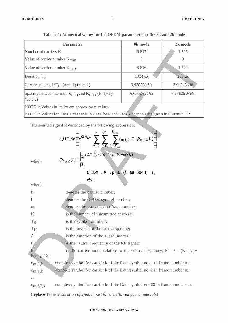
Table 2.1: Numerical values for the OFDM parameters for the 8k and 2k mode
Parameter 8k mode 2k mode
Number of carriers K 6 817 1 705
Value of carrier number Kmin 0 0
Value of carrier number Kmax 6 816 1 704
Duration TU 1024 µs 256 µs
Carrier spacing 1/TU (note 1) (note 2) 0,976563 Hz 3,90625 Hz
Spacing between carriers Kmin and Kmax (K-1)/TU(note 2)
6,65625 MHz 6,65625 MHz
NOTE 1: Values in italics are approximate values.
NOTE 2: Values for 7 MHz channels. Values for 6 and 8 MHz channels are given in Clause 2.1.39
The emitted signal is described by the following expression:
s t e c tj f tm l k m l k
k K
K
lm
c( ) Re ( ), , , ,
min
max
= ×
===
∞
∑∑∑2
0
67
0
π ψ
where ψπ
m l k
j t l T m T
t e TU s s
, ,
( )
( ) =
− − × − × ×2 68
0
k’ ∆
( ) ( )l m T t l m T
elses s+ × × ≤ ≤ + × + ×68 68 1
where:
k denotes the carrier number;
l denotes the OFDM symbol number;
m denotes the transmission frame number;
K is the number of transmitted carriers;
TS is the symbol duration;
TU is the inverse of the carrier spacing;
∆ is the duration of the guard interval;
fc is the central frequency of the RF signal;
k’ is the carrier index relative to the centre frequency, k’ = k - (Kmax +Kmin) / 2;
cm,0,k complex symbol for carrier k of the Data symbol no. 1 in frame number m;
cm,1,k complex symbol for carrier k of the Data symbol no. 2 in frame number m;
...
cm,67,k complex symbol for carrier k of the Data symbol no. 68 in frame number m.
(replace Table 5 Duration of symbol part for the allowed guard intervals)
DRAFT ONLY 10 DRAFT ONLY
21/01/99 12:52
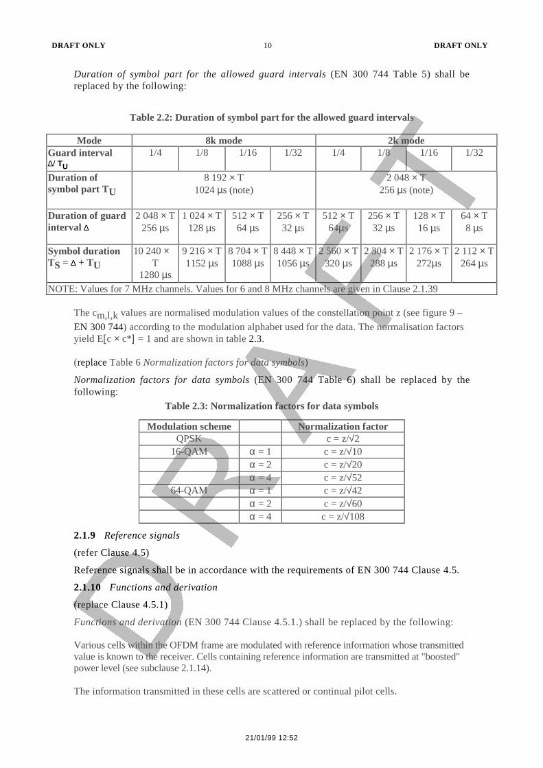
Duration of symbol part for the allowed guard intervals (EN 300 744 Table 5) shall bereplaced by the following:
Table 2.2: Duration of symbol part for the allowed guard intervals
Mode 8k mode 2k modeGuard interval∆/ TU
1/4 1/8 1/16 1/32 1/4 1/8 1/16 1/32
Duration ofsymbol part TU
8 192 × T1024 µs (note)
2 048 × T256 µs (note)
Duration of guardinterval ∆
2 048 × T256 µs
1 024 × T128 µs
512 × T64 µs
256 × T32 µs
512 × T64µs
256 × T32 µs
128 × T16 µs
64 × T8 µs
Symbol durationTS = ∆ + TU
10 240 ×T
1280 µs
9 216 × T1152 µs
8 704 × T1088 µs
8 448 × T1056 µs
2 560 × T320 µs
2 304 × T288 µs
2 176 × T272µs
2 112 × T264 µs
NOTE: Values for 7 MHz channels. Values for 6 and 8 MHz channels are given in Clause 2.1.39
The cm,l,k values are normalised modulation values of the constellation point z (see figure 9 –
EN 300 744) according to the modulation alphabet used for the data. The normalisation factorsyield E[c × c*] = 1 and are shown in table 2.3.
(replace Table 6 Normalization factors for data symbols)
Normalization factors for data symbols (EN 300 744 Table 6) shall be replaced by thefollowing:
Table 2.3: Normalization factors for data symbols
Modulation scheme Normalization factorQPSK c = z/√2
16-QAM α = 1 c = z/√10α = 2 c = z/√20α = 4 c = z/√52
64-QAM α = 1 c = z/√42α = 2 c = z/√60α = 4 c = z/√108
2.1.9 Reference signals
(refer Clause 4.5)
Reference signals shall be in accordance with the requirements of EN 300 744 Clause 4.5.
2.1.10 Functions and derivation
(replace Clause 4.5.1)
Functions and derivation (EN 300 744 Clause 4.5.1.) shall be replaced by the following:
Various cells within the OFDM frame are modulated with reference information whose transmittedvalue is known to the receiver. Cells containing reference information are transmitted at "boosted"power level (see subclause 2.1.14).
The information transmitted in these cells are scattered or continual pilot cells.

DRAFT ONLY 11 DRAFT ONLY
17070.CDR.DOC 21/01/99 12:52
Each continual pilot coincides with a scattered pilot every fourth symbol; the number of usefuldata carriers is constant from symbol to symbol: 1 512 useful carriers in 2k mode and 6 048useful carriers in 8k mode. The number of continual pilots per symbol remains constantwhereas the number of scattered pilots varies between symbols in the pattern shown in Figure11. The number of occasions continual pilots coincide with the scattered pilots varies betweensymbols and has a pattern of 12, 11, 11, 11, 12 (45, 44, 44, 44, 45) for 2K (8K).
The value of the scattered or continual pilot information is derived from a PRBS (Pseudo RandomBinary Sequence) which is a series of values, one for each of the transmitted carriers (see subclause2.1.11).
2.1.11 Definition of reference sequence
(refer Clause 4.5.2)
Definition of reference sequences shall be in accordance with the requirements of EN 300744 Clause 4.5.2.
2.1.12 Location of Scattered Pilot Cells
(replace Clause 4.5.3)
Location of Scattered Pilot Cells (EN 300 744 Clause 4.5.3.) shall be replaced by thefollowing:
Reference information, taken from the reference sequence, is transmitted in scattered pilot cellsin every symbol. Scattered pilot cells are always transmitted at the "boosted" power level (seesubclause 2.1.14). Thus the corresponding modulation is given by:
Re{cm,l,k} = 4 / 3 × 2 (½ - wk)Im{cm,l,k,} = 0
Where m is the frame index, k is the frequency index of the carriers and l is the time index ofthe symbols.
For the symbol of index l ( ranging from 0 to 67), carriers for which index k belongs to thesubset{k = K min + 3 × (l mod 4) + 12p p integer, p ≥ 0, k ∈ [Kmin; Kmax] } are scattered pilots.
Where p is an integer that takes all possible values greater than or equal to zero, provided thatthe resulting valuefor k does not exceed the valid range [Kmin;Kmax].
The pilot insertion pattern is shown in figure 2.1.
(replace Figure 11 Frame structure)
Frame structure (EN 300 744 Figure 11) shall be replaced by the following:

DRAFT ONLY 12 DRAFT ONLY
21/01/99 12:52
Number of scattered pilots for 2K (8K) per symbol
Figure 2.1: Frame Structure
2.1.13 Location of continual pilot carriers
(refer Clause 4.5.4)
Location of continual pilot carriers shall be in accordance with the requirements of EN 300744 Clause 4.5.4.
2.1.14 Amplitudes of all reference information
(replace Clause 4.5.5)
Amplitudes of reference information (EN 300 744 Clause 4.5.5.) shall be replaced by thefollowing:
As explained in subclause 2.1.8 the modulation of all data cells is normalised so that E[c ×c∗] = 1.
All cells which are continual or scattered pilots, i.e. they are members of the sets defined insubclauses 2.1.12 or 2.1.13, are transmitted at boosted power so that for these E[c × c∗] = 16/9(2,5 dB higher)
2.1.15 Transmission Parameter Signalling (TPS)
(refer Clause 4.6)
Transmission parameter signalling shall be in accordance with the requirements of EN 300744 Clause 4.6.
TPS pilot
142 (568)142 (568)142 (568)143 (569)142 (568) *
*
*
*
symbol 3
symbol 1
Kmin=0
TPS pilots (except 1 687 / 6 799) and continual pilots between Kmin and Kmax are notboosted pilot * Scattered pilot coincident with continual pilot
Kmax = 1 704 if 2KKmax = 6 816 if 8K
symbol 2
symbol 0symbol 67
Continual pilotsContinual pilots
Boosted pilots highlighted (176 per symbol for 2Kmode, 701 for 8K
symbol 4symbol 5
TPS pilots (not boosted)data
symbol 64symbol 65symbol 66
143 (569)142 (568)142 (568)142 (568)143 (569)
DRAFT ONLY 13 DRAFT ONLY
17070.CDR.DOC 21/01/99 12:52
2.1.16 Scope of the TPS
(refer Clause 4.6.1)
Scope of TPS shall be in accordance with the requirements of EN 300 744 Clause 4.6.1.
2.1.17 TPS transmission format
(replace Clause 4.6.2)
TPS transmission format (EN 300 744 Clause 4.6.2.) shall be replaced by the following:
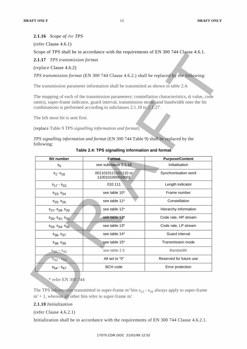
The transmission parameter information shall be transmitted as shown in table 2.4.
The mapping of each of the transmission parameters: constellation characteristics, α value, coderate(s), super-frame indicator, guard interval, transmission mode, and bandwidth onto the bitcombinations is performed according to subclauses 2.1.18 to 2.1.27.
The left most bit is sent first.
(replace Table 9 TPS signalling information and format)
TPS signalling information and format (EN 300 744 Table 9) shall be replaced by thefollowing:
Table 2.4: TPS signalling information and format
Bit number Format Purpose/Content
s0 see subclause 2.1.18 Initialisation
s1- s16 0011010111101110 or1100101000010001
Synchronisation word
s17 - s22 010 111 Length indicator
s23, s24 see table 10* Frame number
s25, s26 see table 11* Constellation
s27, s28, s29 see table 12* Hierarchy information
s30, s31, s32 see table 13* Code rate, HP stream
s33, s34, s35 see table 13* Code rate, LP stream
s36, s37 see table 14* Guard interval
s38, s39 see table 15* Transmission mode
s40 – s41 see table 2.5 Bandwidth
S42 - s53 All set to "0" Reserved for future use
s54 - s67 BCH code Error protection
* refer EN 300 744
The TPS information transmitted in super-frame m’ bits s25 - s39 always apply to super-framem’ + 1, whereas all other bits refer to super-frame m’.
2.1.18 Initialization
(refer Clause 4.6.2.1)
Initialization shall be in accordance with the requirements of EN 300 744 Clause 4.6.2.1.

DRAFT ONLY 14 DRAFT ONLY
21/01/99 12:52
2.1.19 Synchronization
(refer Clause 4.6.2.2)
Synchronization shall be in accordance with the requirements of EN 300 744 Clause4.6.2.2.
2.1.20 TPS length indicator
(refer Clause 4.6.2.3)
TPS length indicator shall be in accordance with the requirements of EN 300 744 Clause4.6.2.3.
2.1.21 Frame number
(refer Clause 4.6.2.4)
Frame number shall be in accordance with the requirements of EN 300 744 Clause 4.6.2.4.
2.1.22 Constellation
(refer Clause 4.6.2.5)
Constellation shall be in accordance with the requirements of EN 300 744 Clause 4.6.2.5.
2.1.23 Hierarchy information
(refer Clause 4.6.2.6)
Hierarchy information shall be in accordance with the requirements of EN 300 744 Clause4.6.2.6.
2.1.24 Code rates
(refer Clause 4.6.2.7)
Code rates shall be in accordance with the requirements of EN 300 744 Clause 4.6.2.7.
2.1.25 Guard intervals
(refer Clause 4.6.2.8)
Guard intervals shall be in accordance with the requirements of EN 300 744 Clause 4.6.2.8.
2.1.26 Transmission mode
(refer Clause 4.6.2.9)
Transmission mode shall be in accordance with the requirements of EN 300 744 Clause4.6.2.9.
2.1.27 Error protection of TPS
(refer Clause 4.6.2.10)
Error protection of TPS shall be in accordance with the requirements of EN 300 744 Clause4.6.2.10.
2.1.28 Bandwidth**
Two bits are used to signal the bandwidth of the channel.
DRAFT ONLY 15 DRAFT ONLY
17070.CDR.DOC 21/01/99 12:52
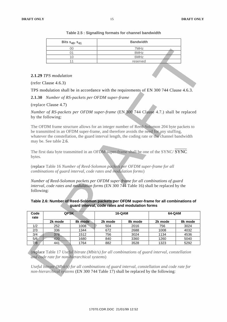
Table 2.5 : Signalling formats for channel bandwidth
Bits s40, s41 Bandwidth
00 7MHz01 8MHz10 6MHz11 reserved
2.1.29 TPS modulation
(refer Clause 4.6.3)
TPS modulation shall be in accordance with the requirements of EN 300 744 Clause 4.6.3.
2.1.30 Number of RS-packets per OFDM super-frame
(replace Clause 4.7)
Number of RS-packets per OFDM super-frame (EN 300 744 Clause 4.7.) shall be replacedby the following:
The OFDM frame structure allows for an integer number of Reed-Solomon 204 byte packets tobe transmitted in an OFDM super-frame, and therefore avoids the need for any stuffing,whatever the constellation, the guard interval length, the coding rate or the channel bandwidthmay be. See table 2.6.
The first data byte transmitted in an OFDM super-frame shall be one of the SYNC/ SYNCbytes.
(replace Table 16 Number of Reed-Solomon packets per OFDM super-frame for allcombinations of guard interval, code rates and modulation forms)
Number of Reed-Solomon packets per OFDM super-frame for all combinations of guardinterval, code rates and modulation forms (EN 300 744 Table 16) shall be replaced by thefollowing:
Table 2.6: Number of Reed-Solomon packets per OFDM super-frame for all combinations ofguard interval, code rates and modulation forms
Coderate
QPSK 16-QAM 64-QAM
2k mode 8k mode 2k mode 8k mode 2k mode 8k mode1/2 252 1008 504 2016 756 30242/3 336 1344 672 2688 1008 40323/4 378 1512 756 3024 1134 45365/6 420 1680 840 3360 1260 50407/8 441 1764 882 3528 1323 5292
(replace Table 17 Useful bitrate (Mbit/s) for all combinations of guard interval, constellationand code rate for non-hierarchical systems)
Useful bitrate (Mbit/s) for all combinations of guard interval, constellation and code rate fornon-hierarchical systems (EN 300 744 Table 17) shall be replaced by the following:
DRAFT ONLY 16 DRAFT ONLY
21/01/99 12:52
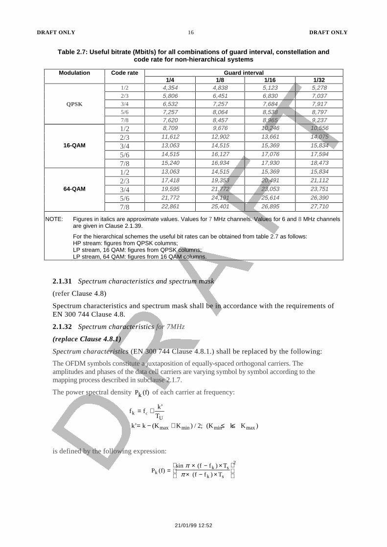
Table 2.7: Useful bitrate (Mbit/s) for all combinations of guard interval, constellation andcode rate for non-hierarchical systems
Modulation Code rate Guard interval1/4 1/8 1/16 1/32
1/2 4,354 4,838 5,123 5,2782/3 5,806 6,451 6,830 7,037
QPSK 3/4 6,532 7,257 7,684 7,9175/6 7,257 8,064 8,538 8,7977/8 7,620 8,457 8,965 9,237
1/2 8,709 9,676 10,246 10,556
2/3 11,612 12,902 13,661 14,075
16-QAM 3/4 13,063 14,515 15,369 15,834
5/6 14,515 16,127 17,076 17,594
7/8 15,240 16,934 17,930 18,473
1/2 13,063 14,515 15,369 15,834
2/3 17,418 19,353 20,491 21,11264-QAM 3/4 19,595 21,772 23,053 23,751
5/6 21,772 24,191 25,614 26,390
7/8 22,861 25,401 26,895 27,710
NOTE: Figures in italics are approximate values. Values for 7 MHz channels. Values for 6 and 8 MHz channelsare given in Clause 2.1.39.
For the hierarchical schemes the useful bit rates can be obtained from table 2.7 as follows:HP stream: figures from QPSK columns;LP stream, 16 QAM: figures from QPSK columns;LP stream, 64 QAM: figures from 16 QAM columns.
2.1.31 Spectrum characteristics and spectrum mask
(refer Clause 4.8)
Spectrum characteristics and spectrum mask shall be in accordance with the requirements ofEN 300 744 Clause 4.8.
2.1.32 Spectrum characteristics for 7MHz
(replace Clause 4.8.1)
Spectrum characteristics (EN 300 744 Clause 4.8.1.) shall be replaced by the following:
The OFDM symbols constitute a juxtaposition of equally-spaced orthogonal carriers. Theamplitudes and phases of the data cell carriers are varying symbol by symbol according to themapping process described in subclause 2.1.7.
The power spectral density Pk (f) of each carrier at frequency:
f fk’
T
k’ k (K K ) / 2; (K k K )
kU
max min min max
c= +
= − + ≤ ≤
is defined by the following expression:
P (f)sin (f f ) T
(f f ) Tkk s
k s
2
=× − ×
× − ×
ππ
DRAFT ONLY 17 DRAFT ONLY
17070.CDR.DOC 21/01/99 12:52
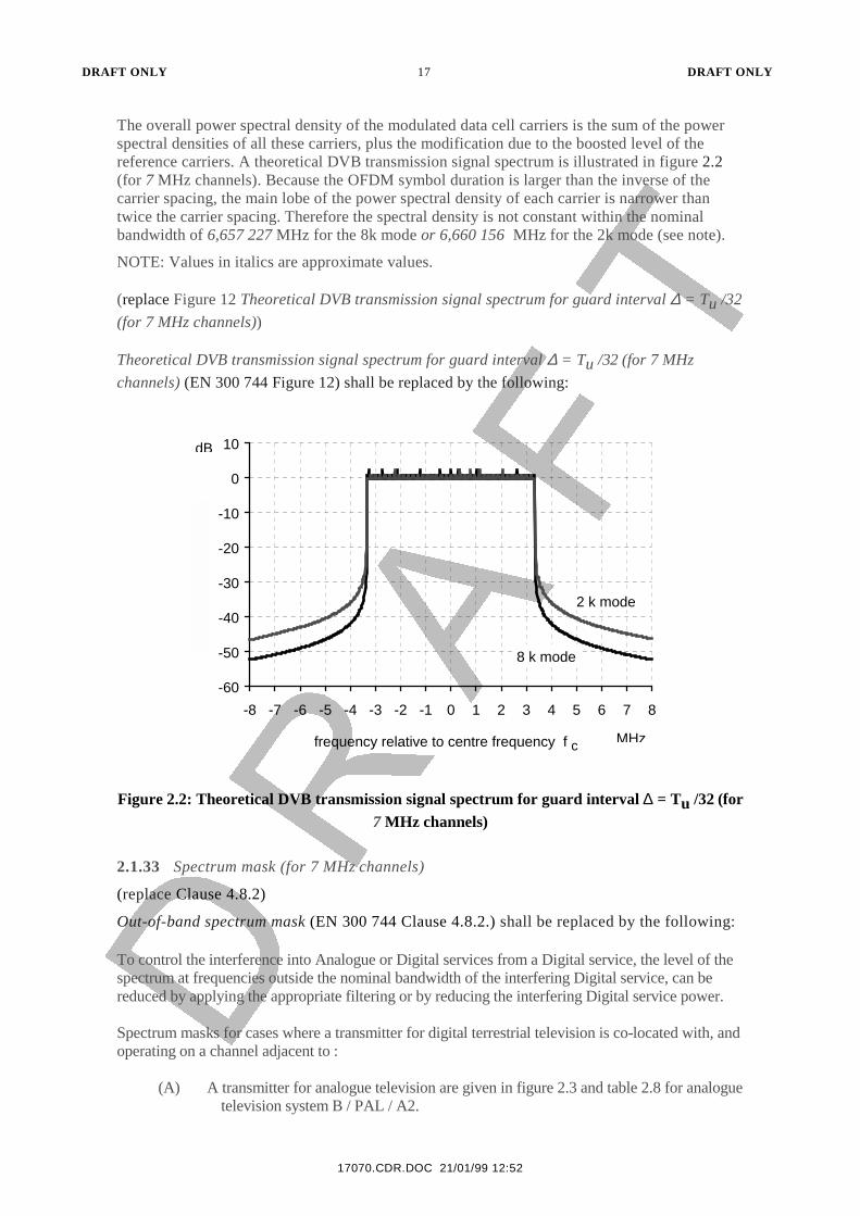
The overall power spectral density of the modulated data cell carriers is the sum of the powerspectral densities of all these carriers, plus the modification due to the boosted level of thereference carriers. A theoretical DVB transmission signal spectrum is illustrated in figure 2.2(for 7 MHz channels). Because the OFDM symbol duration is larger than the inverse of thecarrier spacing, the main lobe of the power spectral density of each carrier is narrower thantwice the carrier spacing. Therefore the spectral density is not constant within the nominalbandwidth of 6,657 227 MHz for the 8k mode or 6,660 156 MHz for the 2k mode (see note).
NOTE: Values in italics are approximate values.
(replace Figure 12 Theoretical DVB transmission signal spectrum for guard interval ∆ = Tu /32
(for 7 MHz channels))
Theoretical DVB transmission signal spectrum for guard interval ∆ = Tu /32 (for 7 MHz
channels) (EN 300 744 Figure 12) shall be replaced by the following:
-60
-50
-40
-30
-20
-10
0
10
-8 -7 -6 -5 -4 -3 -2 -1 0 1 2 3 4 5 6 7 8
frequency relative to centre frequency f c MHz
dB
2 k mode
8 k mode
Figure 2.2: Theoretical DVB transmission signal spectrum for guard interval ∆ = Tu /32 (for7 MHz channels)
2.1.33 Spectrum mask (for 7 MHz channels)
(replace Clause 4.8.2)
Out-of-band spectrum mask (EN 300 744 Clause 4.8.2.) shall be replaced by the following:
To control the interference into Analogue or Digital services from a Digital service, the level of thespectrum at frequencies outside the nominal bandwidth of the interfering Digital service, can bereduced by applying the appropriate filtering or by reducing the interfering Digital service power.
Spectrum masks for cases where a transmitter for digital terrestrial television is co-located with, andoperating on a channel adjacent to :
(A) A transmitter for analogue television are given in figure 2.3 and table 2.8 for analoguetelevision system B / PAL / A2.
DRAFT ONLY 18 DRAFT ONLY
21/01/99 12:52
(B) A transmitter for digital television are given in figure 2.4 and table 2.9 for COFDMdigital television with a modulation mode of 64QAM with an FEC of 2/3.
The masks shown in figure 2.3 and 2.4 cover the minimum protection needed for analogue anddigital television where the analogue and the digital television transmitters are co-located and areapplicable for cases where:
- no polarisation discrimination between digital and analogue television is used.
The masks are to be used for the comparison of ERP’s of the wanted and unwantedservices. Such comparison may be provided from calculation from the actual transmitterspectrum output and antenna system gains.
The masks provide the limit to the power and the out of band products of the unwantedDigital service. The mask levels are fixed in relationship to the wanted service, hence theactual mask of the interfering service must be derived from the actual operating power ofthe interfering service and its relationship to the wanted analogue or digital service.
(replace Figure 13 Spectrum mask for a digital terrestrial television transmitter operating witha co-located lower or upper adjacent channel analogue television transmitter)
Spectrum mask for a digital terrestrial television transmitter operating with a co-located loweror upper adjacent channel analogue television transmitter (EN 300 744 Figure 13) shall bereplaced by the following:

DRAFT ONLY 19 DRAFT ONLY
17070.CDR.DOC 21/01/99 12:52
Figure 2.3 : Spectrum mask for a digital terrestrial television transmitter operating with aco-located lower or upper adjacent channel analogue television transmitter
(replace Table 18 Breakpoints for spectrum mask)
Breakpoints for spectrum mask (EN 300 744 Table 18) shall be replaced by the following:Table 2.8: Breakpoints for spectrum mask
.1.a.i.A.1 Lower Breakpoints
Relative frequency(- MHz) 0 3,3 3,4 3,5 3,51 3,75 4,75 8,25 9,25 10,25
Relative level(dB / 4 kHz) -29 -29 -50 -56 -56 -56 -74.5 -77 -77 -77
.1.a.i.A.2 Upper Breakpoints
Relative frequency(MHz) 0 3,5 3,7 3,8 4,7 4,75 10 10,5
Relative level(dB / 4 kHz) -29 -29 -29 -40 -77 -77 -77 -100
(replace Figure 14 Spectrum mask for a digital terrestrial television transmitter operating witha co-located lower or upper adjacent channel digital terrestrial television transmitter)
Spectrum mask for a digital terrestrial television transmitter operating with a co-located loweror upper adjacent channel digital terrestrial television transmitter (EN 300 744 Figure 14) shallbe replaced by the following:
DTTB Spectrum Mask (Analogue Upper & Lower Adjacent)
-100
-90
-80
-70
-60
-50
-40
-30
-20
-10
0
-12 -11 -10 -9 -8 -7 -6 -5 -4 -3 -2 -1 0 1 2 3 4 5 6 7 8 9 10 11 12
Frequency relative to centre DTTB channel (MHz)
Sp
ectr
al D
ensi
ty (
dB/4
KH
z)
'77%���&:��FDUULHU�SRZHU3$/��SHDN�V\QF��YLVLRQ�FDUULHU�SRZHU '77%�6SHFWUDO�'HQVLW\
HJ�#����G%�UHI��3$//RZHU�$QDORJXH�&KDQQHO 8SSHU�$QDORJXH&KDQQHO
DRAFT ONLY 20 DRAFT ONLY
21/01/99 12:52
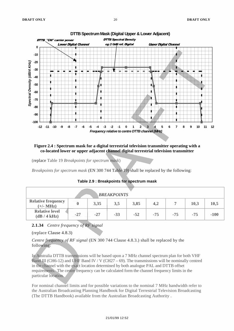
Figure 2.4 : Spectrum mask for a digital terrestrial television transmitter operating with aco-located lower or upper adjacent channel digital terrestrial television transmitter
(replace Table 19 Breakpoints for spectrum mask)
Breakpoints for spectrum mask (EN 300 744 Table 19) shall be replaced by the following:
Table 2.9 : Breakpoints for spectrum mask
BREAKPOINTS
Relative frequency(+/- MHz) 0 3,35 3,5 3,85 4,2 7 10,3 10,5
Relative level(dB / 4 kHz) -27 -27 -33 -52 -75 -75 -75 -100
2.1.34 Centre frequency of RF signal
(replace Clause 4.8.3)
Centre frequency of RF signal (EN 300 744 Clause 4.8.3.) shall be replaced by thefollowing:
In Australia DTTB transmissions will be based upon a 7 MHz channel spectrum plan for both VHFBand III (CH6-12) and UHF Band IV / V (CH27 – 69). The transmissions will be nominally centredin the channel with the exact location determined by both analogue PAL and DTTB offsetrequirements. The centre frequency can be calculated form the channel frequency limits in theparticular location.
For nominal channel limits and for possible variations to the nominal 7 MHz bandwidth refer tothe Australian Broadcasting Planning Handbook for Digital Terrestrial Television Broadcasting(The DTTB Handbook) available from the Australian Broadcasting Authority .
DTTB Spectrum Mask (Digital Upper & Lower Adjacent)
-100
-90
-80
-70
-60
-50
-40
-30
-20
-10
0
-12 -11 -10 -9 -8 -7 -6 -5 -4 -3 -2 -1 0 1 2 3 4 5 6 7 8 9 10 11 12Frequency relative to centre DTTB channel (MHz)
Spe
ctra
l Den
sity
(dB
/4 K
Hz)
'77%���&:��FDUULHU�SRZHU
/RZHU�'LJLWDO�&KDQQHO
'77%�6SHFWUDO�'HQVLW\
HJ�#��G%�UHI��'LJLWDO 8SSHU�'LJLWDO�&KDQQHO

DRAFT ONLY 21 DRAFT ONLY
17070.CDR.DOC 21/01/99 12:52
2.1.35 Simulated system performance for 7MHz channels
(refer Annex A)
Simulated system performance (EN 300 744 Annex A.) shall be replaced by the following:
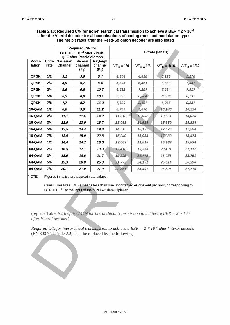
Tables 2.10, 2.11 and 2.12 give simulated performance anticipating "perfect channel estimation andwithout phase noise" of channel coding and modulation combinations, and are subject toconfirmation by testing.
These results are given for the Gaussian channel, Ricean channel (F1) and Rayleigh channel
(P1). F1 and P1 are described in Clause 2.1.36.
Associated useful bit rates available are also indicated as a function of the guard interval to activesymbol duration for the four different values of guard interval.
(replace Table A1 Required C/N for non-hierarchical transmission to achieve a BER = 2 × 10⁻⁴
after the Viterbi decoder for all combinations of coding rates and modulation types. The net bitrates after the Reed-Solomon decoder are also listed)
Required C/N for non-hierarchical transmission to achieve a BER = 2 × 10⁻⁴ after the Viterbidecoder for all combinations of coding rates and modulation types. The net bit rates after theReed-Solomon decoder are also listed (EN 300 744 Table A1) shall be replaced by thefollowing:
DRAFT ONLY 22 DRAFT ONLY
21/01/99 12:52
Table 2.10: Required C/N for non-hierarchical transmission to achieve a BER = 2 × 10⁻⁴
after the Viterbi decoder for all combinations of coding rates and modulation types.The net bit rates after the Reed-Solomon decoder are also listed
Required C/N forBER = 2 × 10⁻⁴ after ViterbiQEF after Reed-Solomon
Bitrate (Mbit/s)
Modu-lation
Coderate
GaussianChannel
Riceanchannel
(F1)
Rayleighchannel
(P1)∆/ΤU = 1/4 ∆/ΤU = 1/8 ∆/ΤU = 1/16 ∆/ΤU = 1/32
QPSK 1/2 3,1 3,6 5,4 4,354 4,838 5,123 5,278
QPSK 2/3 4,9 5,7 8,4 5,806 6,451 6,830 7,037
QPSK 3/4 5,9 6,8 10,7 6,532 7,257 7,684 7,917
QPSK 5/6 6,9 8,0 13,1 7,257 8,064 8,538 8,797
QPSK 7/8 7,7 8,7 16,3 7,620 8,467 8,965 9,237
16-QAM 1/2 8,8 9,6 11,2 8,709 9,676 10,246 10,556
16-QAM 2/3 11,1 11,6 14,2 11,612 12,902 13,661 14,075
16-QAM 3/4 12,5 13,0 16,7 13,063 14,515 15,369 15,834
16-QAM 5/6 13,5 14,4 19,3 14,515 16,127 17,076 17,594
16-QAM 7/8 13,9 15,0 22,8 15,240 16,934 17,930 18,473
64-QAM 1/2 14,4 14,7 16,0 13,063 14,515 15,369 15,834
64-QAM 2/3 16,5 17,1 19,3 17,418 19,353 20,491 21,112
64-QAM 3/4 18,0 18,6 21,7 19,595 21,772 23,053 23,751
64-QAM 5/6 19,3 20,0 25,3 21,772 24,191 25,614 26,390
64-QAM 7/8 20,1 21,0 27,9 22,861 25,401 26,895 27,710
NOTE: Figures in italics are approximate values.
Quasi Error Free (QEF) means less than one uncorrected error event per hour, corresponding toBER = 10-11 at the input of the MPEG-2 demultiplexer.
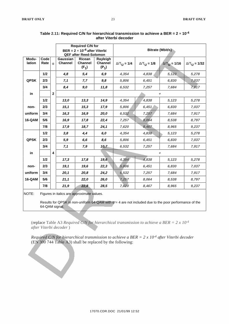
(replace Table A2 Required C/N for hierarchical transmission to achieve a BER = 2 × 10⁻⁴
after Viterbi decoder)
Required C/N for hierarchical transmission to achieve a BER = 2 × 10⁻⁴ after Viterbi decoder(EN 300 744 Table A2) shall be replaced by the following:
DRAFT ONLY 23 DRAFT ONLY
17070.CDR.DOC 21/01/99 12:52
Table 2.11: Required C/N for hierarchical transmission to achieve a BER = 2 × 10⁻⁴
after Viterbi decoder
Required C/N forBER = 2 × 10⁻⁴ after ViterbiQEF after Reed-Solomon
Bitrate (Mbit/s)
Modu-lation
CodeRate α
GaussianChannel
RiceanChannel
(F1)
RayleighChannel
(P1)∆/ΤU = 1/4 ∆/ΤU = 1/8 ∆/ΤU = 1/16 ∆/ΤU = 1/32
1/2 4,8 5,4 6,9 4,354 4,838 5,123 5,278
QPSK 2/3 7,1 7,7 9,8 5,806 6,451 6,830 7,037
3/4 8,4 9,0 11,8 6,532 7,257 7,684 7,917
in 2 +
1/2 13,0 13,3 14,9 4,354 4,838 5,123 5,278
non- 2/3 15,1 15,3 17,9 5,806 6,451 6,830 7,037
uniform 3/4 16,3 16,9 20,0 6,532 7,257 7,684 7,917
16-QAM 5/6 16,9 17,8 22,4 7,257 8,064 8,538 8,797
7/8 17,9 18,7 24,1 7,620 8,467 8,965 9,237
1/2 3,8 4,4 6,0 4,354 4,838 5,123 5,278
QPSK 2/3 5,9 6,6 8,6 5,806 6,451 6,830 7,037
3/4 7,1 7,9 10,7 6,532 7,257 7,684 7,917
in 4 +
1/2 17,3 17,8 19,6 4,354 4,838 5,123 5,278
non- 2/3 19,1 19,6 22,3 5,806 6,451 6,830 7,037
uniform 3/4 20,1 20,8 24,2 6,532 7,257 7,684 7,917
16-QAM 5/6 21,1 22,0 26,0 7,257 8,064 8,538 8,797
7/8 21,9 22,8 28,5 7,620 8,467 8,965 9,237
NOTE: Figures in italics are approximate values.
Results for QPSK in non-uniform 64-QAM with α = 4 are not included due to the poor performance of the64-QAM signal.
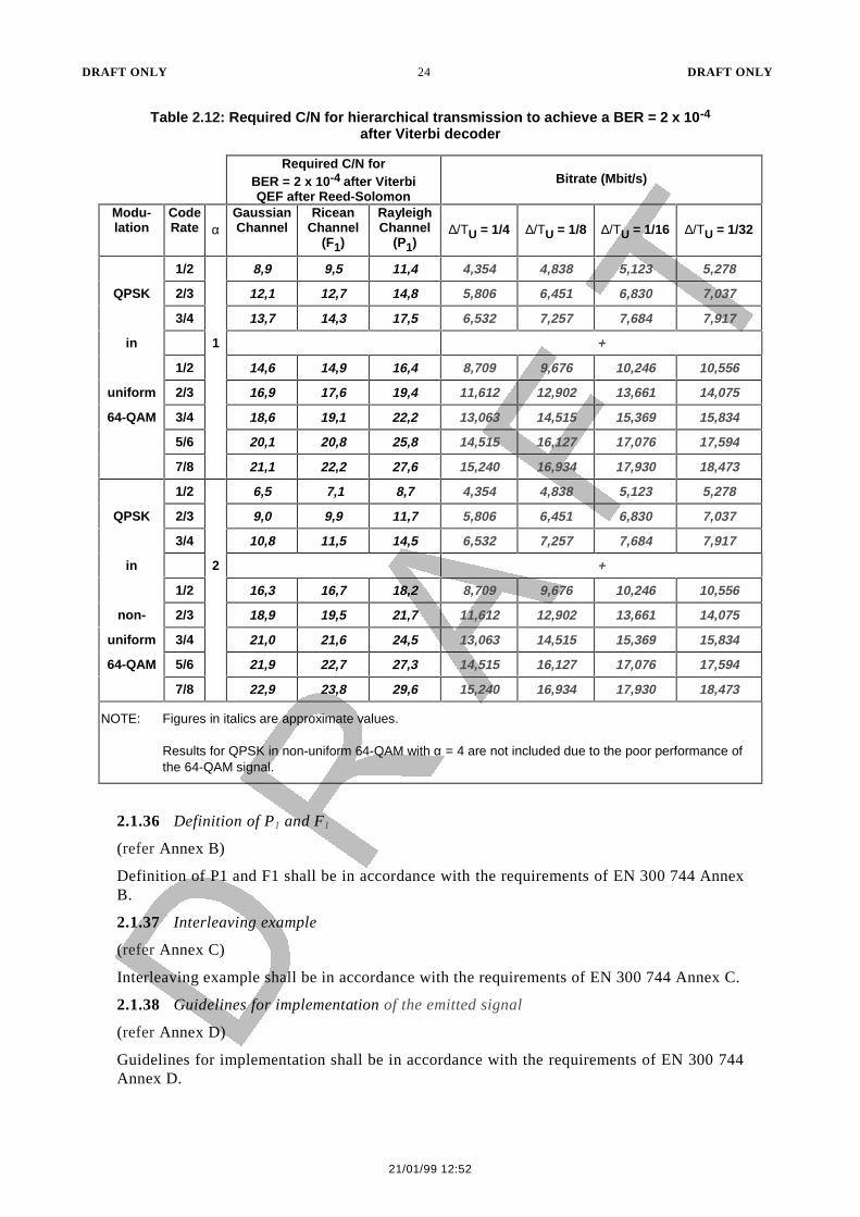
(replace Table A3 Required C/N for hierarchical transmission to achieve a BER = 2 x 10⁻⁴
after Viterbi decoder )
Required C/N for hierarchical transmission to achieve a BER = 2 x 10⁻⁴ after Viterbi decoder(EN 300 744 Table A3) shall be replaced by the following:
DRAFT ONLY 24 DRAFT ONLY
21/01/99 12:52
Table 2.12: Required C/N for hierarchical transmission to achieve a BER = 2 x 10⁻⁴
after Viterbi decoder
Required C/N forBER = 2 x 10⁻⁴ after ViterbiQEF after Reed-Solomon
Bitrate (Mbit/s)
Modu-lation
CodeRate α
GaussianChannel
RiceanChannel
(F1)
RayleighChannel
(P1)∆/ΤU = 1/4 ∆/ΤU = 1/8 ∆/ΤU = 1/16 ∆/ΤU = 1/32
1/2 8,9 9,5 11,4 4,354 4,838 5,123 5,278
QPSK 2/3 12,1 12,7 14,8 5,806 6,451 6,830 7,037
3/4 13,7 14,3 17,5 6,532 7,257 7,684 7,917
in 1 +
1/2 14,6 14,9 16,4 8,709 9,676 10,246 10,556
uniform 2/3 16,9 17,6 19,4 11,612 12,902 13,661 14,075
64-QAM 3/4 18,6 19,1 22,2 13,063 14,515 15,369 15,834
5/6 20,1 20,8 25,8 14,515 16,127 17,076 17,594
7/8 21,1 22,2 27,6 15,240 16,934 17,930 18,473
1/2 6,5 7,1 8,7 4,354 4,838 5,123 5,278
QPSK 2/3 9,0 9,9 11,7 5,806 6,451 6,830 7,037
3/4 10,8 11,5 14,5 6,532 7,257 7,684 7,917
in 2 +
1/2 16,3 16,7 18,2 8,709 9,676 10,246 10,556
non- 2/3 18,9 19,5 21,7 11,612 12,902 13,661 14,075
uniform 3/4 21,0 21,6 24,5 13,063 14,515 15,369 15,834
64-QAM 5/6 21,9 22,7 27,3 14,515 16,127 17,076 17,594
7/8 22,9 23,8 29,6 15,240 16,934 17,930 18,473
NOTE: Figures in italics are approximate values.
Results for QPSK in non-uniform 64-QAM with α = 4 are not included due to the poor performance ofthe 64-QAM signal.
2.1.36 Definition of P1 and F1
(refer Annex B)
Definition of P1 and F1 shall be in accordance with the requirements of EN 300 744 AnnexB.
2.1.37 Interleaving example
(refer Annex C)
Interleaving example shall be in accordance with the requirements of EN 300 744 Annex C.
2.1.38 Guidelines for implementation of the emitted signal
(refer Annex D)
Guidelines for implementation shall be in accordance with the requirements of EN 300 744Annex D.
DRAFT ONLY 25 DRAFT ONLY
17070.CDR.DOC 21/01/99 12:52
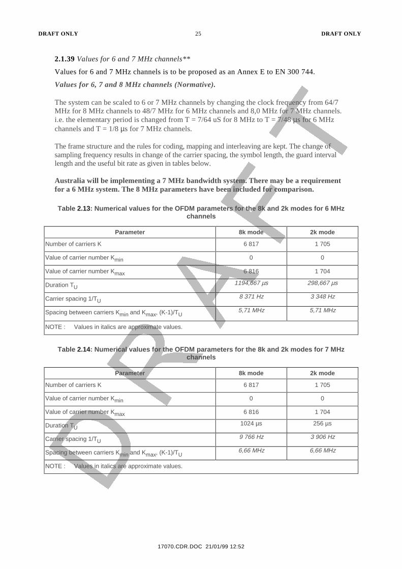
2.1.39 Values for 6 and 7 MHz channels**
Values for 6 and 7 MHz channels is to be proposed as an Annex E to EN 300 744.
Values for 6, 7 and 8 MHz channels (Normative).
The system can be scaled to 6 or 7 MHz channels by changing the clock frequency from 64/7MHz for 8 MHz channels to 48/7 MHz for 6 MHz channels and 8,0 MHz for 7 MHz channels.i.e. the elementary period is changed from T = 7/64 uS for 8 MHz to T = 7/48 µs for 6 MHzchannels and T = 1/8 µs for 7 MHz channels.
The frame structure and the rules for coding, mapping and interleaving are kept. The change ofsampling frequency results in change of the carrier spacing, the symbol length, the guard intervallength and the useful bit rate as given in tables below.
Australia will be implementing a 7 MHz bandwidth system. There may be a requirementfor a 6 MHz system. The 8 MHz parameters have been included for comparison.
Table 2.13: Numerical values for the OFDM parameters for the 8k and 2k modes for 6 MHzchannels
Parameter 8k mode 2k mode
Number of carriers K 6 817 1 705
Value of carrier number Kmin 0 0
Value of carrier number Kmax 6 816 1 704
Duration TU1194,667 µs 298,667 µs
Carrier spacing 1/TU8 371 Hz 3 348 Hz
Spacing between carriers Kmin and Kmax, (K-1)/TU5,71 MHz 5,71 MHz
NOTE : Values in italics are approximate values.
Table 2.14: Numerical values for the OFDM parameters for the 8k and 2k modes for 7 MHzchannels
Parameter 8k mode 2k mode
Number of carriers K 6 817 1 705
Value of carrier number Kmin 0 0
Value of carrier number Kmax 6 816 1 704
Duration TU1024 µs 256 µs
Carrier spacing 1/TU9 766 Hz 3 906 Hz
Spacing between carriers Kmin and Kmax, (K-1)/TU6,66 MHz 6,66 MHz
NOTE : Values in italics are approximate values.
DRAFT ONLY 26 DRAFT ONLY
21/01/99 12:52
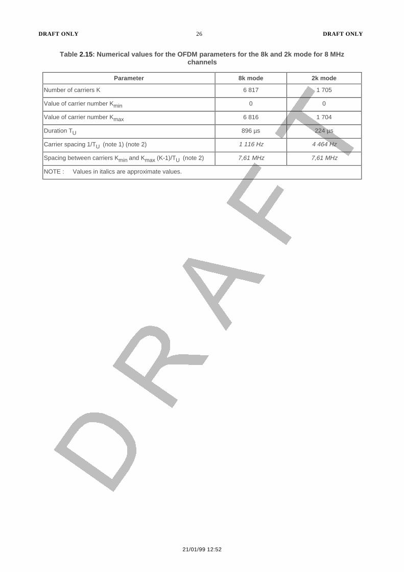
Table 2.15: Numerical values for the OFDM parameters for the 8k and 2k mode for 8 MHzchannels
Parameter 8k mode 2k mode
Number of carriers K 6 817 1 705
Value of carrier number Kmin 0 0
Value of carrier number Kmax 6 816 1 704
Duration TU 896 µs 224 µs
Carrier spacing 1/TU (note 1) (note 2) 1 116 Hz 4 464 Hz
Spacing between carriers Kmin and Kmax (K-1)/TU (note 2) 7,61 MHz 7,61 MHz
NOTE : Values in italics are approximate values.
DRAFT ONLY 27 DRAFT ONLY
17070.CDR.DOC 21/01/99 12:52
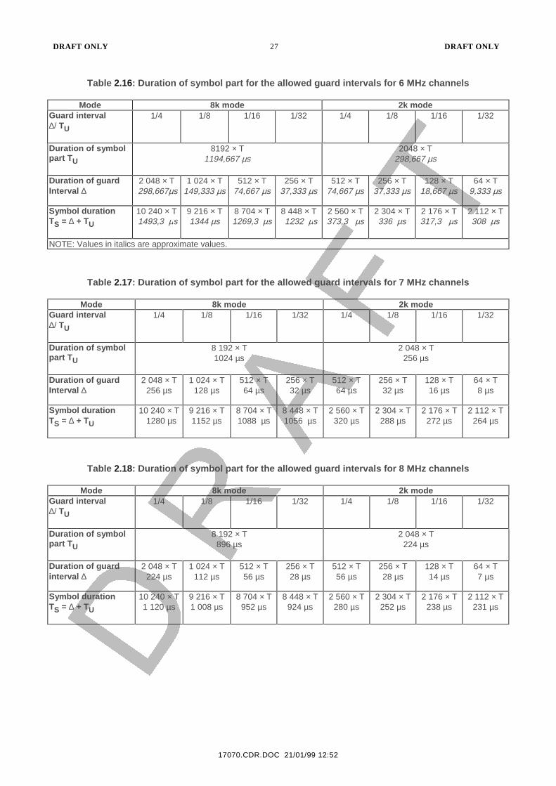
Table 2.16: Duration of symbol part for the allowed guard intervals for 6 MHz channels
Mode 8k mode 2k modeGuard interval∆/ TU
1/4 1/8 1/16 1/32 1/4 1/8 1/16 1/32
Duration of symbolpart TU
8192 × T1194,667 µs
2048 × T298,667 µs
Duration of guardInterval ∆
2 048 × T 298,667µs
1 024 × T149,333 µs
512 × T74,667 µs
256 × T37,333 µs
512 × T74,667 µs
256 × T37,333 µs
128 × T18,667 µs
64 × T9,333 µs
Symbol durationTS = ∆ + TU
10 240 × T 1493,3 µs
9 216 × T1344 µs
8 704 × T1269,3 µs
8 448 × T 1232 µs
2 560 × T373,3 µs
2 304 × T336 µs
2 176 × T317,3 µs
2 112 × T308 µs
NOTE: Values in italics are approximate values.
Table 2.17: Duration of symbol part for the allowed guard intervals for 7 MHz channels
Mode 8k mode 2k modeGuard interval∆/ TU
1/4 1/8 1/16 1/32 1/4 1/8 1/16 1/32
Duration of symbolpart TU
8 192 × T1024 µs
2 048 × T256 µs
Duration of guardInterval ∆
2 048 × T256 µs
1 024 × T128 µs
512 × T64 µs
256 × T32 µs
512 × T64 µs
256 × T32 µs
128 × T16 µs
64 × T8 µs
Symbol durationTS = ∆ + TU
10 240 × T 1280 µs
9 216 × T1152 µs
8 704 × T1088 µs
8 448 × T1056 µs
2 560 × T320 µs
2 304 × T288 µs
2 176 × T272 µs
2 112 × T264 µs
Table 2.18: Duration of symbol part for the allowed guard intervals for 8 MHz channels
Mode 8k mode 2k modeGuard interval∆/ TU
1/4 1/8 1/16 1/32 1/4 1/8 1/16 1/32
Duration of symbolpart TU
8 192 × T896 µs
2 048 × T224 µs
Duration of guardinterval ∆
2 048 × T224 µs
1 024 × T112 µs
512 × T56 µs
256 × T28 µs
512 × T56 µs
256 × T28 µs
128 × T14 µs
64 × T7 µs
Symbol durationTS = ∆ + TU
10 240 × T1 120 µs
9 216 × T1 008 µs
8 704 × T952 µs
8 448 × T924 µs
2 560 × T280 µs
2 304 × T252 µs
2 176 × T238 µs
2 112 × T231 µs
DRAFT ONLY 28 DRAFT ONLY
21/01/99 16:01
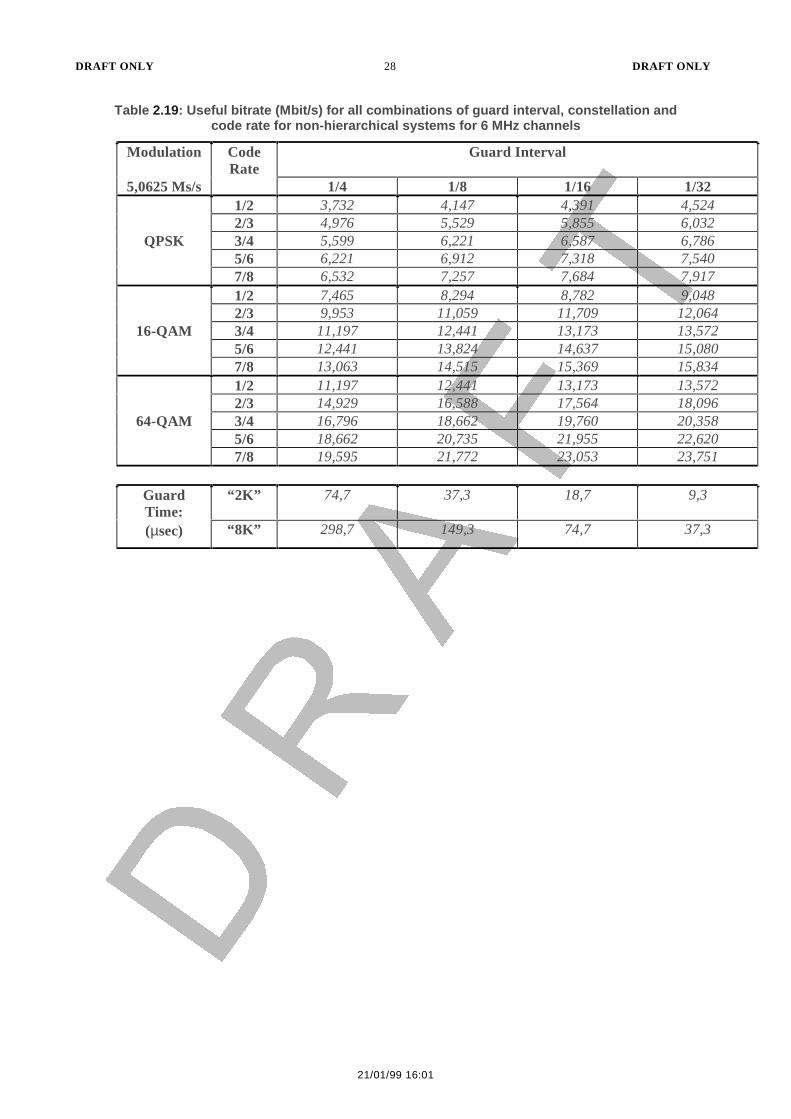
Table 2.19: Useful bitrate (Mbit/s) for all combinations of guard interval, constellation andcode rate for non-hierarchical systems for 6 MHz channels
Modulation Guard Interval
5,0625 Ms/s
CodeRate
1/4 1/8 1/16 1/321/2 3,732 4,147 4,391 4,5242/3 4,976 5,529 5,855 6,032
QPSK 3/4 5,599 6,221 6,587 6,7865/6 6,221 6,912 7,318 7,5407/8 6,532 7,257 7,684 7,9171/2 7,465 8,294 8,782 9,0482/3 9,953 11,059 11,709 12,064
16-QAM 3/4 11,197 12,441 13,173 13,5725/6 12,441 13,824 14,637 15,0807/8 13,063 14,515 15,369 15,8341/2 11,197 12,441 13,173 13,5722/3 14,929 16,588 17,564 18,096
64-QAM 3/4 16,796 18,662 19,760 20,3585/6 18,662 20,735 21,955 22,6207/8 19,595 21,772 23,053 23,751
GuardTime:
“2K” 74,7 37,3 18,7 9,3
(µsec) “8K” 298,7 149,3 74,7 37,3
DRAFT ONLY 29 DRAFT ONLY
17070.CDR.DOC 21/01/99 16:01
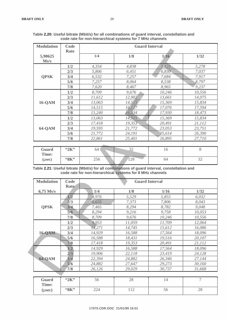
Table 2.20: Useful bitrate (Mbit/s) for all combinations of guard interval, constellation andcode rate for non-hierarchical systems for 7 MHz channels
Modulation Guard Interval
5,90625Ms/s
CodeRate
1/4 1/8 1/16 1/32
1/2 4,354 4,838 5,123 5,2782/3 5,806 6,451 6,830 7,037
QPSK 3/4 6,532 7,257 7,684 7,9175/6 7,257 8,064 8,538 8,7977/8 7,620 8,467 8,965 9,2371/2 8,709 9,676 10,246 10,5562/3 11,612 12,902 13,661 14,075
16-QAM 3/4 13,063 14,515 15,369 15,8345/6 14,515 16,127 17,076 17,5947/8 15,240 16,934 17,930 18,4731/2 13,063 14,515 15,369 15,8342/3 17,418 19,353 20,491 21,112
64-QAM 3/4 19,595 21,772 23,053 23,7515/6 21,772 24,191 25,614 26,3907/8 22,861 25,401 26,895 27,710
GuardTime:
“2K” 64 32 16 8
(µsec) “8K” 256 128 64 32
Table 2.21: Useful bitrate (Mbit/s) for all combinations of guard interval, constellation andcode rate for non-hierarchical systems for 8 MHz channels
Modulation Guard Interval
6,75 Ms/s
CodeRate
1/4 1/8 1/16 1/321/2 4,976 5,529 5,855 6,0322/3 6,635 7,373 7,806 8,043
QPSK 3/4 7,465 8,294 8,782 9,0485/6 8,294 9,216 9,758 10,0537/8 8,709 9,676 10,246 10,5561/2 9,953 11,059 11,709 12,0642/3 13,271 14,745 15,612 16,086
16-QAM 3/4 14,929 16,588 17,564 18,0965/6 16,588 18,431 19,516 20,1077/8 17,418 19,353 20,491 21,1121/2 14,929 16,588 17,564 18,0962/3 19,906 22,118 23,419 24,128
64-QAM 3/4 22,394 24,882 26,346 27,1445/6 24,882 27,647 29,273 30,1607/8 26,126 29,029 30,737 31,668
GuardTime:
“2K” 56 28 14 7
(µsec) “8K” 224 112 56 28

DRAFT ONLY 30 DRAFT ONLY
21/01/99 16:01
2.2 Transmission aspects
(refer TS 101 191 Digital Video Broadcasting (DVB); Implementation guidelines forDVB terrestrial services; Transmission aspects)
2.2.1 General Description
(replace Clause 4)
General Description (TS 101 191 Clause 4.) shall be replaced by the following:
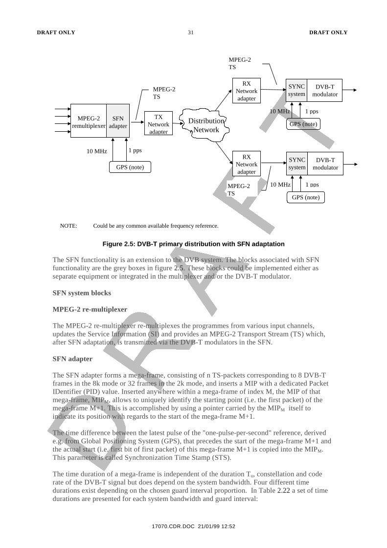
Figure 2.5 shows a block diagram of a complete SFN system.
(replace Figure 1 DVB-T primary distribution with SFN adaptation)
DVB-T primary distribution with SFN adaptation (TS 101 191 Figure 1) shall be replaced bythe following:
DRAFT ONLY 31 DRAFT ONLY
17070.CDR.DOC 21/01/99 12:52
MPEG-2remultiplexer
SFNadapter
MPEG-2TS
TXNetworkadapter
DistributionNetwork
RXNetworkadapter
RXNetworkadapter
GPS (note)
10 MHz 1 pps
DVB-Tmodulator
SYNCsystem
GPS (note)
10 MHz 1 pps
DVB-Tmodulator
SYNCsystem
GPS (note)
10 MHz 1 pps
MPEG-2TS
MPEG-2TS
NOTE: Could be any common available frequency reference.
Figure 2.5: DVB-T primary distribution with SFN adaptation
The SFN functionality is an extension to the DVB system. The blocks associated with SFNfunctionality are the grey boxes in figure 2.5. These blocks could be implemented either asseparate equipment or integrated in the multiplexer and/or the DVB-T modulator.
SFN system blocks
MPEG-2 re-multiplexer
The MPEG-2 re-multiplexer re-multiplexes the programmes from various input channels,updates the Service Information (SI) and provides an MPEG-2 Transport Stream (TS) which,after SFN adaptation, is transmitted via the DVB-T modulators in the SFN.
SFN adapter
The SFN adapter forms a mega-frame, consisting of n TS-packets corresponding to 8 DVB-Tframes in the 8k mode or 32 frames in the 2k mode, and inserts a MIP with a dedicated PacketIDentifier (PID) value. Inserted anywhere within a mega-frame of index M, the MIP of thatmega-frame, MIPM, allows to uniquely identify the starting point (i.e. the first packet) of themega-frame M+1. This is accomplished by using a pointer carried by the MIPM itself toindicate its position with regards to the start of the mega-frame M+1.
The time difference between the latest pulse of the "one-pulse-per-second" reference, derivede.g. from Global Positioning System (GPS), that precedes the start of the mega-frame M+1 andthe actual start (i.e. first bit of first packet) of this mega-frame M+1 is copied into the MIPM.This parameter is called Synchronization Time Stamp (STS).
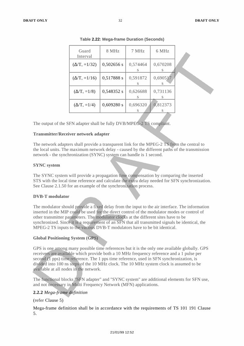
The time duration of a mega-frame is independent of the duration Tu, constellation and coderate of the DVB-T signal but does depend on the system bandwidth. Four different timedurations exist depending on the chosen guard interval proportion. In Table 2.22 a set of timedurations are presented for each system bandwidth and guard interval:
DRAFT ONLY 32 DRAFT ONLY
21/01/99 12:52
Table 2.22: Mega-frame Duration (Seconds)
GuardInterval
8 MHz 7 MHz 6 MHz
(∆/Tu =1/32) 0,502656 s 0,574464s
0,670208s
(∆/Tu =1/16) 0,517888 s 0,591872s
0,690517s
(∆/Tu =1/8) 0,548352 s 0,626688s
0,731136s
(∆/Tu =1/4) 0,609280 s 0,696320s
0,812373s
The output of the SFN adapter shall be fully DVB/MPEG-2 TS compliant.
Transmitter/Receiver network adapter
The network adapters shall provide a transparent link for the MPEG-2 TS from the central tothe local units. The maximum network delay - caused by the different paths of the transmissionnetwork - the synchronization (SYNC) system can handle is 1 second.
SYNC system
The SYNC system will provide a propagation time compensation by comparing the insertedSTS with the local time reference and calculate the extra delay needed for SFN synchronization.See Clause 2.1.50 for an example of the synchronization process.
DVB-T modulator
The modulator should provide a fixed delay from the input to the air interface. The informationinserted in the MIP could be used for the direct control of the modulator modes or control ofother transmitter parameters. The modulator clocks at the different sites have to besynchronized. Since it is a requirement of an SFN that all transmitted signals be identical, theMPEG-2 TS inputs to the various DVB-T modulators have to be bit identical.
Global Positioning System (GPS)
GPS is one among many possible time references but it is the only one available globally. GPSreceivers are available which provide both a 10 MHz frequency reference and a 1 pulse persecond (1 pps) time reference. The 1 pps time reference, used in SFN synchronization, isdivided into 100 ns steps of the 10 MHz clock. The 10 MHz system clock is assumed to beavailable at all nodes in the network.
The functional blocks "SFN adapter" and "SYNC system" are additional elements for SFN use,and not necessary in Multi Frequency Network (MFN) applications.
2.2.2 Mega-frame definition
(refer Clause 5)
Mega-frame definition shall be in accordance with the requirements of TS 101 191 Clause5.
DRAFT ONLY 33 DRAFT ONLY
17070.CDR.DOC 21/01/99 12:52
2.2.3 Mega-frame Initialization Packet (MIP)
(replace Clause 6)
Mega-frame Initialization Packet (MIP) (TS 101 191 Clause 6.) shall be replaced by thefollowing:
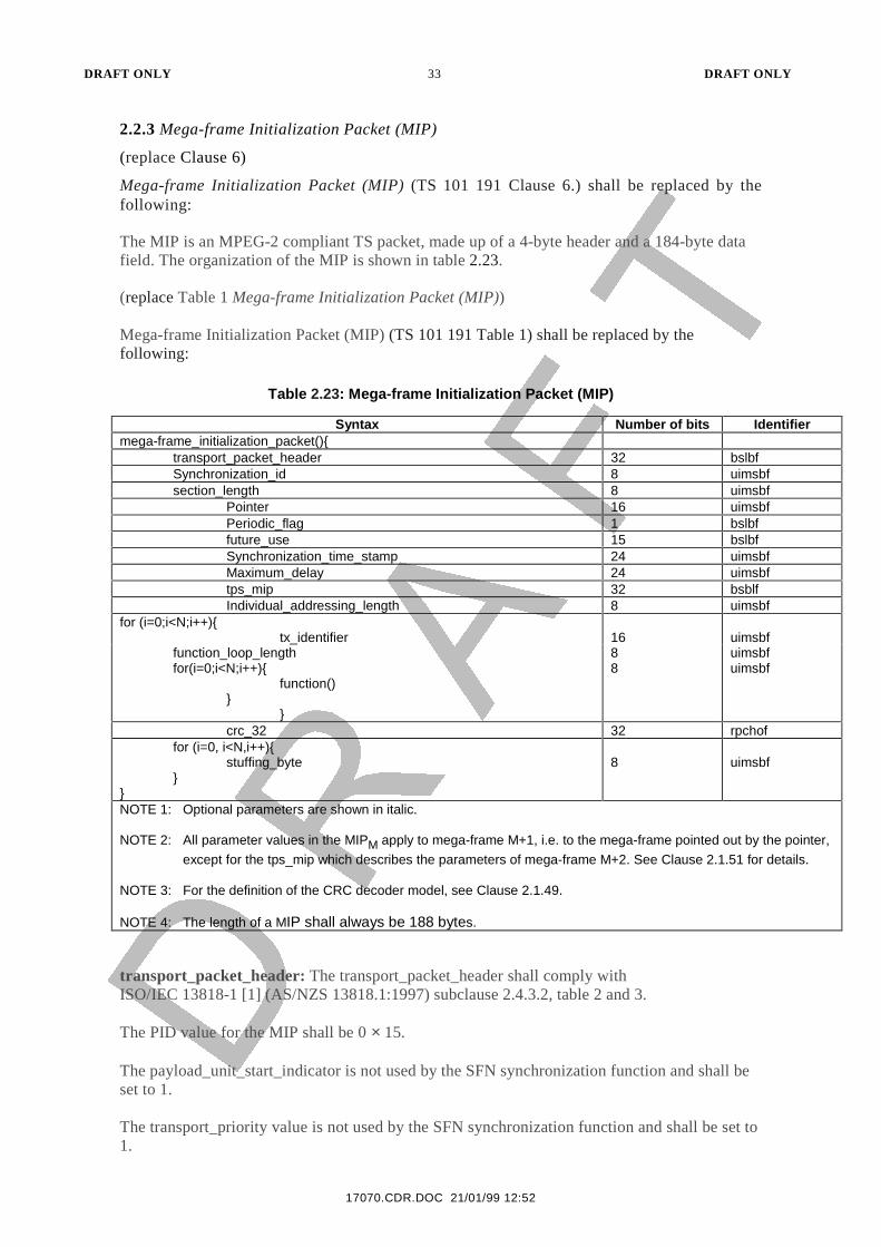
The MIP is an MPEG-2 compliant TS packet, made up of a 4-byte header and a 184-byte datafield. The organization of the MIP is shown in table 2.23.
(replace Table 1 Mega-frame Initialization Packet (MIP))
Mega-frame Initialization Packet (MIP) (TS 101 191 Table 1) shall be replaced by thefollowing:
Table 2.23: Mega-frame Initialization Packet (MIP)
Syntax Number of bits Identifiermega-frame_initialization_packet(){
transport_packet_header 32 bslbfSynchronization_id 8 uimsbfsection_length 8 uimsbf
Pointer 16 uimsbfPeriodic_flag 1 bslbffuture_use 15 bslbfSynchronization_time_stamp 24 uimsbfMaximum_delay 24 uimsbftps_mip 32 bsblfIndividual_addressing_length 8 uimsbf
for (i=0;i<N;i++){tx_identifier 16 uimsbf
function_loop_lengthfor(i=0;i<N;i++){
function()}
}
88
uimsbfuimsbf
crc_32 32 rpchoffor (i=0, i<N,i++){
stuffing_byte}
}
8 uimsbf
NOTE 1: Optional parameters are shown in italic.
NOTE 2: All parameter values in the MIPM apply to mega-frame M+1, i.e. to the mega-frame pointed out by the pointer,
except for the tps_mip which describes the parameters of mega-frame M+2. See Clause 2.1.51 for details.
NOTE 3: For the definition of the CRC decoder model, see Clause 2.1.49.
NOTE 4: The length of a MIP shall always be 188 bytes.
transport_packet_header: The transport_packet_header shall comply withISO/IEC 13818-1 [1] (AS/NZS 13818.1:1997) subclause 2.4.3.2, table 2 and 3.
The PID value for the MIP shall be 0 × 15.
The payload_unit_start_indicator is not used by the SFN synchronization function and shall beset to 1.
The transport_priority value is not used by the SFN synchronization function and shall be set to1.

DRAFT ONLY 34 DRAFT ONLY
21/01/99 12:52
The transport_scrambling_control value shall be set to 00 (not scrambled).
The adaptation_field_control value shall be set to 01 (payload only).
All other parameters are according to ISO/IEC 13818-1 [1] (AS/NZS 13818.1:1997) subclause2.4.3.2.
The Transport Packet Header (TPH) is mandatory.
DRAFT ONLY 35 DRAFT ONLY
17070.CDR.DOC 21/01/99 12:52
Mandatory SFN parameters
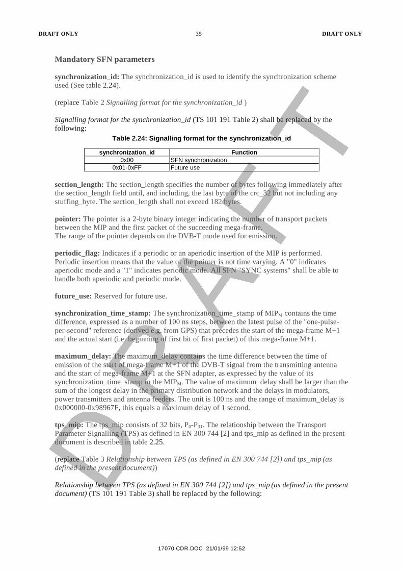
synchronization_id: The synchronization_id is used to identify the synchronization schemeused (See table 2.24).
(replace Table 2 Signalling format for the synchronization_id )
Signalling format for the synchronization_id (TS 101 191 Table 2) shall be replaced by thefollowing:
Table 2.24: Signalling format for the synchronization_id
synchronization_id Function0x00 SFN synchronization
0x01-0xFF Future use
section_length: The section_length specifies the number of bytes following immediately afterthe section_length field until, and including, the last byte of the crc_32 but not including anystuffing_byte. The section_length shall not exceed 182 bytes.
pointer: The pointer is a 2-byte binary integer indicating the number of transport packetsbetween the MIP and the first packet of the succeeding mega-frame.The range of the pointer depends on the DVB-T mode used for emission.
periodic_flag: Indicates if a periodic or an aperiodic insertion of the MIP is performed.Periodic insertion means that the value of the pointer is not time varying. A "0" indicatesaperiodic mode and a "1" indicates periodic mode. All SFN "SYNC systems" shall be able tohandle both aperiodic and periodic mode.
future_use: Reserved for future use.
synchronization_time_stamp: The synchronization_time_stamp of MIPM contains the timedifference, expressed as a number of 100 ns steps, between the latest pulse of the "one-pulse-per-second" reference (derived e.g. from GPS) that precedes the start of the mega-frame M+1and the actual start (i.e. beginning of first bit of first packet) of this mega-frame M+1.
maximum_delay: The maximum_delay contains the time difference between the time ofemission of the start of mega-frame M+1 of the DVB-T signal from the transmitting antennaand the start of mega-frame M+1 at the SFN adapter, as expressed by the value of itssynchronization_time_stamp in the MIPM. The value of maximum_delay shall be larger than thesum of the longest delay in the primary distribution network and the delays in modulators,power transmitters and antenna feeders. The unit is 100 ns and the range of maximum_delay is0x000000-0x98967F, this equals a maximum delay of 1 second.
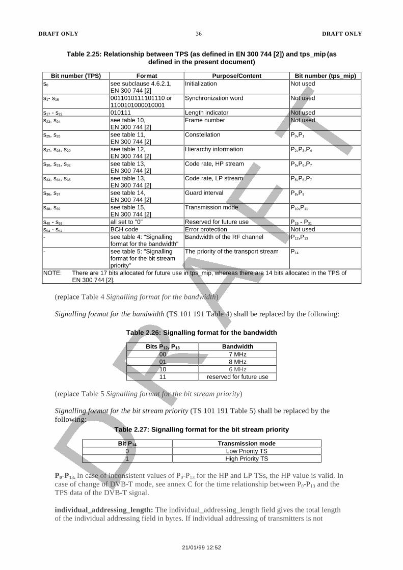
tps_mip: The tps_mip consists of 32 bits, P0-P31. The relationship between the TransportParameter Signalling (TPS) as defined in EN 300 744 [2] and tps_mip as defined in the presentdocument is described in table 2.25.
(replace Table 3 Relationship between TPS (as defined in EN 300 744 [2]) and tps_mip (asdefined in the present document))
Relationship between TPS (as defined in EN 300 744 [2]) and tps_mip (as defined in the presentdocument) (TS 101 191 Table 3) shall be replaced by the following:
DRAFT ONLY 36 DRAFT ONLY
21/01/99 12:52
Table 2.25: Relationship between TPS (as defined in EN 300 744 [2]) and tps_mip (asdefined in the present document)
Bit number (TPS) Format Purpose/Content Bit number (tps_mip)s0 see subclause 4.6.2.1,
EN 300 744 [2]Initialization Not used
s1- s16 0011010111101110 or1100101000010001
Synchronization word Not used
s17 - s22 010111 Length indicator Not useds23, s24 see table 10,
EN 300 744 [2]Frame number Not used
s25, s26 see table 11,EN 300 744 [2]
Constellation P0,P1
s27, s28, s29 see table 12,EN 300 744 [2]
Hierarchy information P2,P3,P4
s30, s31, s32 see table 13,EN 300 744 [2]
Code rate, HP stream P5,P6,P7
s33, s34, s35 see table 13,EN 300 744 [2]
Code rate, LP stream P5,P6,P7
s36, s37 see table 14,EN 300 744 [2]
Guard interval P8,P9
s38, s39 see table 15,EN 300 744 [2]
Transmission mode P10,P11
s40 - s53 all set to "0" Reserved for future use P15 - P31
s54 - s67 BCH code Error protection Not used- see table 4: "Signalling
format for the bandwidth"Bandwidth of the RF channel P12,P13
- see table 5: "Signallingformat for the bit streampriority"
The priority of the transport stream P14
NOTE: There are 17 bits allocated for future use in tps_mip, whereas there are 14 bits allocated in the TPS ofEN 300 744 [2].
(replace Table 4 Signalling format for the bandwidth)
Signalling format for the bandwidth (TS 101 191 Table 4) shall be replaced by the following:
Table 2.26: Signalling format for the bandwidth
Bits P12, P13 Bandwidth00 7 MHz01 8 MHz10 6 MHz11 reserved for future use
(replace Table 5 Signalling format for the bit stream priority)
Signalling format for the bit stream priority (TS 101 191 Table 5) shall be replaced by thefollowing:
Table 2.27: Signalling format for the bit stream priority
Bit P14 Transmission mode0 Low Priority TS1 High Priority TS
P0-P13: In case of inconsistent values of P0-P13 for the HP and LP TSs, the HP value is valid. Incase of change of DVB-T mode, see annex C for the time relationship between P0-P13 and theTPS data of the DVB-T signal.
individual_addressing_length: The individual_addressing_length field gives the total lengthof the individual addressing field in bytes. If individual addressing of transmitters is not
DRAFT ONLY 37 DRAFT ONLY
17070.CDR.DOC 21/01/99 12:52
performed the field value is 0x00, indicating that the crc_32 immediately follows theindividual_addressing_length.
crc_32: This 32 bit crc_32 field contains the CRC value that gives a zero output of the registersin the decoder defined in Clause 2.1.49 of the present document, after processing all of thebytes in the MIP, excluding the stuffing bytes.
stuffing_byte: Every stuffing_byte has the value 0xFF.
Optional MIP section parameters
tx_identifier: The tx_identifier is a 16 bit word used to address an individual transmitter. Thetx_identifier value 0x0000 is used as a broadcast address to address all transmitters in thenetwork.
function_loop_length: The function_loop_length field gives the total length of the functionloop field in bytes.
function: The functions are described in subclause 2.2.4.
2.2.4 Functions
(refer Clause 6.1)
Functions shall be in accordance with the requirements of TS 101 191 Clause 6.1.
2.2.5 Transmitter time offset functions
(refer Clause 6.1.1)
Transmitter time offset functions shall be in accordance with the requirements TS 101 191Clause 6.1.1.
2.2.6 Transmitter frequency offset functions
(refer Clause 6.1.2)
Transmitter frequency offset functions shall be in accordance with the requirements of TS101 191 Clause 6.1.2.
2.2.7 Transmitter power function
(refer Clause 6.1.3)
Transmitter power function shall be in accordance with the requirements of TS 101 191Clause 6.1.3.
2.2.8 Private data function
(refer Clause 6.1.4)
Private data function shall be in accordance with the requirements of TS 101 191 Clause6.1.4.
2.2.9 CRC decoder model
(refer Annex A)
CRC decoder model shall be in accordance with the requirements of TS 101 191 Annex A.
2.2.10 Functional description of SFN synchronization
(refer Annex B)
Functional description of SFN synchronization shall be in accordance with the requirementsof TS 101 191 Annex B.
DRAFT ONLY 38 DRAFT ONLY
21/01/99 12:52
2.2.11 Reconfiguration of DVB-T modulator parameters by using the MIP
(refer Annex C)
Reconfiguration of DVB-T modulator parameters by using the MIP shall be in accordancewith the requirements of TS 101 191 Annex C.
3 MULTIPLEX AND TRANSPORT STREAM
3.1 Use of MPEG-2 Systems, Video and Audio
(refer ETR 154 Digital Video Broadcasting (DVB); Implementation Guidelines for theUse of MPEG-2 Systems, Video and Audio in satellite, cable and terrestrialbroadcasting applications )
3.1.1 Systems layer
(refer Clause 4)
Systems Layer shall be in accordance with the requirements of ETR 154 Clause 4.
3.1.2 Broadcast bitstreams and Baseline IRDs
(refer Clause 4.1)
Broadcast bitstreams and baseline IRDs shall be in accordance with the requirements ofETR 154 Clause 4.1.
3.1.3 Introduction (ISO/IEC 13818-1 section 0)
(refer Clause 4.1.1)
Introduction (ISO/IEC 13818-1 (AS/NZS 13818.1:1997) section 0) shall be in accordancewith the requirements of ETR 154 Clause 4.1.1.
3.1.4 Packetized Elementary Stream (PES)(ISO/IEC 13818-1, section 0.4)
(refer Clause 4.1.2)
Packetized Elementary Stream (PES) (ISO/IEC 13818-1 (AS/NZS 13818.1:1997), section0.4) shall be in accordance with the requirements of ETR 154 Clause 4.1.2.
3.1.5 TS system target decoder (ISO/IEC 13818-1, section 2.4.2)
(refer Clause 4.1.3)
TS system target decoder (ISO/IEC 13818-1 (AS/NZS 13818.1:1997), section 2.4.2) shallbe in accordance with the requirements of ETR 154 Clause 4.1.3.
3.1.6 Transport packet layer (ISO/IEC 13818-1, section 2.4.3.2)
(refer Clause 4.1.4)
Transport packet layer (ISO/IEC 13818-1 (AS/NZS 13818.1:1997), section 2.4.3.2) shall bein accordance with the requirements of ETR 154 Clause 4.1.4.
3.1.7 Null packets
(refer Clause 4.1.4.1)
Null packets shall be in accordance with the requirements of ETR 154 Clause 4.1.4.1.
3.1.8 Transport packet header
(refer Clause 4.1.4.2)
Transport packet header shall be in accordance with the requirements of ETR 154 Clause4.1.4.2.
DRAFT ONLY 39 DRAFT ONLY
17070.CDR.DOC 21/01/99 12:52
3.1.9 transport_error_indicator
(refer Clause 4.1.4.2.1)
transport_error_indicator shall be in accordance with the requirements of ETR 154 Clause4.1.4.2.1.
3.1.10 transport _priority
(refer Clause 4.1.4.2.2)
transport_priority shall be in accordance with the requirements of ETR 154Clause 4.1.4.2.2.
3.1.11 transport _scrambling_control
(refer Clause 4.1.4.2.3)
transport_scrambling_control shall be in accordance with the requirements of ETR 154Clause 4.1.4.2.3.
3.1.12 Packet IDentifier (PID) values for Service Information (SI) Tables*
(refer Clause 4.1.4.2.4*)
Packet IDentifier (PID) values for Service Information (SI) Tables shall be in accordancewith the requirements of ETR 154 Clause 4.1.4.2.4.
3.1.13 Adaptation field (ISO/IEC13818-1, section 2.4.3.4)
(refer Clause 4.1.5)
Adaptation field (ISO/IEC 13818-1 (AS/NZS 13818.1:1997), section 2.4.3.4) shall be inaccordance with the requirements of ETR 154 Clause 4.1.5.
3.1.14 Random_access_indicator
(refer Clause 4.1.5.1)
Random_access_indicator shall be in accordance with the requirements of ETR 154 Clause4.1.5.1.
3.1.15 elementary_stream_priority_indicator
(refer Clause 4.1.5.2)
elementary_stream_priority_indicator shall be in accordance with the requirements of ETR154 Clause 4.1.5.2.
3.1.16 Program Clock Reference (PCR)
(refer Clause 4.1.5.3)
Program Clock Reference (PCR) shall be in accordance with the requirements of ETR 154Clause 4.1.5.3.
3.1.17 Other fields
(refer Clause 4.1.5.4)
Other fields shall be in accordance with the requirements of ETR 154 Clause 4.1.5.4.
3.1.18 Packetized Elementary Stream (PES) Packet (ISO/IEC13818-1, section 2.4.3.6)
(refer Clause 4.1.6)
Packetized Elementary Stream (PES) Packet (ISO/IEC 13818-1 (AS/NZS 13818.1:1997),section 2.4.3.6) shall be in accordance with the requirements of ETR 154 Clause 4.1.6.
DRAFT ONLY 40 DRAFT ONLY
21/01/99 12:52
3.1.19 stream_id and stream_type *
(replace Clause 4.1.6.1*)
stream_id and stream_type (ETR 154 Clause 4.1.6.1.) shall be replaced by the following:
Encoding: Elementary streams shall be uniquely identified by stream_id andstream_type in accordance with ISO/IEC 13818-1 (AS/NZS 13818.1:1997)Table 2-18 and Table 2-29.
3.1.20 PES_scrambling_control
(refer Clause 4.1.6.2)
PES_scrambling_control shall be in accordance with the requirements of ETR 154 Clause4.1.6.2.
3.1.21 PES_priority
(refer Clause 4.1.6.3)
PES_priority shall be in accordance with the requirements of ETR 154 Clause 4.1.6.3.
3.1.22 copyright and original_or_copy*
(refer Clause 4.1.6.4*)
copyright and original_or_copy shall be in accordance with the requirements of ETR 154Clause 4.1.6.4.
3.1.23 Trick mode fields
(refer Clause 4.1.6.5)
Trick mode fields shall be in accordance with the requirements of ETR 154 Clause 4.1.6.5.
3.1.24 additional_copy_info*
(refer Clause 4.1.6.6*)
Additional_copy_info shall be in accordance with the requirements of ETR 154 Clause4.1.6.6.
3.1.25 Optional fields
(refer Clause 4.1.6.7)
Optional fields shall be in accordance with the requirements of ETR 154 Clause 4.1.6.7.
3.1.26 PES_extension_field
(refer Clause 4.1.6.8)
PES_extension_field shall be in accordance with the requirements of ETR 154 Clause4.1.6.8.
3.1.27 Program Specific Information (PSI) (ISO/IEC13818-1, section 2.4.4)
(refer Clause 4.1.7)
Program Specific Information (PSI) (ISO/IEC 13818-1 (AS/NZS 13818.1:1997), section2.4.4) shall be in accordance with the requirements of ETR 154 Clause 4.1.7.
3.1.28 Program and elementary stream descriptors (ISO/IEC13818-1, section 2.6)
(refer Clause 4.1.8)
Program and elementary stream descriptors (ISO/IEC 13818-1 (AS/NZS 13818.1:1997),section 2.6) shall be in accordance with the requirements of ETR 154 Clause 4.1.8.
DRAFT ONLY 41 DRAFT ONLY
17070.CDR.DOC 21/01/99 12:52
3.1.29 video_stream_descriptor and audio_stream_descriptor *
(replace Clause 4.1.8.1*)
video_stream_descriptor and audio_stream_descriptor (ETR 154 Clause 4.1.8.1.) shall bereplaced by the following:
Encoding: The video_stream_descriptor shall be used to indicate video streamscontaining still picture data, otherwise these descriptors may be used whenappropriate. If profile_and_level_indication is not present, then the video bit-stream shall comply with the constraints of Main Profile at Main Level. Theappropriate profile_and_level_indication field shall always be transmitted forProfiles and Levels other than Main Profile at Main Level.
If the audio_stream_descriptor is not present, then the audio bit-stream shall notuse sampling frequencies of 16 kHz, 22,05 kHz or 24 kHz, and all audio frames inthe stream shall have the same bit rate.
Decoding: The IRD may use these descriptors when present to determine if it is able todecode the streams
3.1.30 hierarchy_descriptor
(replace Clause 4.1.8.2)
hierarchy_descriptor (ETR 154 Clause 4.1.8.2.) shall be replaced by the following:
Encoding: The hierarchy_descriptor shall be used if, and only if, audio is coded asmore than one hierarchical layer.
3.1.31 registration_descriptor
(refer Clause 4.1.8.3)
registration_descriptor shall be in accordance with the requirements of ETR 154 Clause4.1.8.3.
3.1.32 data_stream_alignment_descriptor
(refer Clause 4.1.8.4)
data_stream_alignment_descriptor shall be in accordance with the requirements of ETR 154Clause 4.1.8.4.
3.1.33 target_background_grid_descriptor
(replace Clause 4.1.8.5)
target_background_grid_descriptor (ETR 154 Clause 4.1.8.5.) shall be replaced by thefollowing:
Encoding: The target_background_grid_descriptor shall be used when the horizontal orvertical resolution exceeds the bounds of Main Profile at Main Level, otherwise itsuse is optional
DRAFT ONLY 42 DRAFT ONLY
21/01/99 12:52
Decoding: If this descriptor is absent, a default grid of 720 x 576 pixels shall be assumedby a 25Hz IRD, a default grid of 720 x 480 pixels shall be assumed by a 30HzIRD. The IRD shall read this descriptor, when present, to override this default.The display of correctly windowed video on background grids other than 720 x576 pixels is optional for a 25Hz SDTV IRD, the display of correctlywindowed video on background grids other than 720 x 480 pixels is optionalfor a 30Hz SDTV IRD.
3.1.34 video_window_descriptor
(refer Clause 4.1.8.6)
video_window_descriptor shall be in accordance with the requirements of ETR 154 Clause4.1.8.6.
3.1.35 Conditional Access CA_descriptor*
(refer Clause 4.1.8.7*)
Conditional Access CA_descriptor shall be in accordance with the requirements of ETR 154Clause 4.1.8.7.
3.1.36 ISO_639_Language_descriptor
(refer Clause 4.1.8.8)
ISO_639_Language_descriptor shall be in accordance with the requirements of ETR 154Clause 4.1.8.8.
3.1.37 system_clock_descriptor
(refer Clause 4.1.8.9)
system_clock_descriptor shall be in accordance with the requirements of ETR 154 Clause4.1.8.9.
3.1.38 multiplex_buffer_utilization_descriptor
(refer Clause 4.1.8.10)
multiplex_buffer_utilization_descriptor shall be in accordance with the requirements ofETR 154 Clause 4.1.8.10.
3.1.39 copyright_descriptor*
(refer Clause 4.1.8.11*)
copyright_descriptor shall be in accordance with the requirements of ETR 154 Clause4.1.8.11.
3.1.40 maximum_bitrate_descriptor
(refer Clause 4.1.8.12)
maximum_bitrate_descriptor shall be in accordance with the requirements of ETR 154Clause 4.1.8.12.
3.1.41 private_data_indicator_descriptor
(refer Clause 4.1.8.13)
private_data_indicator_descriptor shall be in accordance with the requirements of ETR 154Clause 4.1.8.13.
3.1.42 STD_descriptor
(refer Clause 4.1.8.14)
STD_descriptor shall be in accordance with the requirements of ETR 154 Clause 4.1.8.14.
DRAFT ONLY 43 DRAFT ONLY
17070.CDR.DOC 21/01/99 12:52
3.1.43 IBP_descriptor
(refer Clause 4.1.8.15)
IBP_descriptor shall be in accordance with the requirements of ETR 154 Clause 4.1.8.15.
3.1.44 smoothing_buffer_descriptor
(refer Clause 4.1.8.16)
smoothing_buffer_descirptor shall be in accordance with the requirements of ETR 154Clause 4.1.8.16.
3.1.45 Compatibility with ISO/IEC11172-1 (ISO/IEC13818-1, section 2.8)
(refer Clause 4.1.9)
Compatibility with ISO/IEC 11172-1 (AS/NZS 4230) (ISO/IEC 13818-1 (AS/NZS13818.1:1997), section 2.8) shall be in accordance with the requirements of ETR 154Clause 4.1.9.
3.1.46 Storage Media Interoperability *
(replace Clause 4.1.10*)
Storage Media Interoperability (ETR 154 Clause 4.1.10.) shall be replaced by thefollowing:
It is recommended that the total bitrate of the set of components, associated PMT and PCRpackets for an SDTV service anticipated to be recorded by a consumer, should not exceed 9 000000 bit/s. It is recommended that the total bitrate of the set of components, associated PMTand PCR packets for an HDTV service anticipated to be recorded by a consumer, should notexceed 28 000 000 bit/s.
It is recommended that the parameters sb_size and sb_leak_rate in thesmoothing_buffer_descriptor remain constant for the duration of an event. The value of thesb_leak_rate should be the peak attained during the event.
The short_smoothing_buffer_descriptor is defined in ETS 300 468 [6] and guidelines for its useare provided in ETR 211 [7].
3.1.47 Bitstreams from storage applications and IRDs with digital interfaces
(refer Clause 4.2)
Bitstreams from storage applications and IRDs with digital interfaces shall be in accordancewith the requirements of ETR 154 Clause 4.2.
3.1.48 Partial TSs
(refer Clause 4.2.1)
Partial TSs shall be in accordance with the requirements of ETR 154 Clause 4.2.1.
3.1.49 Decoding of Trick Play data (ISO/IEC13818-1, section 2.4.3.7)
(refer Clause 4.2.2)
Decoding of Trick Play data (ISO/IEC 13818-1 (AS/NZS 13818.1:1997), section 2.4.3.7)shall be in accordance with the requirements of ETR 154 Clause 4.2.2.
3.1.50 Video
(replace Clause 5)
Video (ETR 154 Clause 5.) shall be replaced by the following:

DRAFT ONLY 44 DRAFT ONLY
21/01/99 12:52
This clause describes the guidelines for encoding MPEG-2 video in DVB broadcast bit-streams,and for decoding this bit-stream in the IRD.
Subclause 3.1.51 applies to 25 Hz SDTV IRDs and broadcasts intended for reception bysuch IRDs;Subclause 3.1.59 applies to 25 Hz HDTV IRDs and broadcasts intended for receptionby such IRDs;
The video encoding shall conform to ISO/IEC 13818-2 [2] (AS/NZS 13818.2:1997). Some ofthe parameters and fields are not used in the DVB System and these restrictions are describedbelow. The IRD design should be made under the assumption that any legal structure aspermitted by ISO/IEC 13818-2 [2] (AS/NZS 13818.2:1997) may occur in the broadcast streameven if presently reserved or unused.
To allow full compliance to the MPEG-2 standard and upward compatibility with futureenhanced versions, a DVB IRD shall be able to skip over data structures which are currently"reserved", or which correspond to functions not implemented by the IRD.
This clause is based on ISO/IEC 13818-2 [2] (AS/NZS 13818.2:1997).
3.1.51 25 Hz SDTV IRDs and Bitstreams
(refer Clause 5.1)
25 Hz SDTV IRDs and Bitstreams shall be in accordance with the requirements of ETR 154Clause 5.1.
3.1.52 Profile and level
(refer Clause 5.1.1)
Profile and level shall be in accordance with the requirements of ETR 154 Clause 5.1.1.
3.1.53 Frame rate
(refer Clause 5.1.2)
Frame rate shall be in accordance with the requirements of ETR 154 Clause 5.1.2.
3.1.54 Aspect ratio
(refer Clause 5.1.3)
Aspect ratio shall be in accordance with the requirements of ETR 154 Clause 5.1.3.
3.1.55 Luminance resolution
(refer Clause 5.1.4)
Luminance resolution shall be in accordance with the requirements of ETR 154 Clause5.1.4.
3.1.56 Chromaticity Parameters
(refer Clause 5.1.5)
Chromaticity Parameters shall be in accordance with the requirements of ETR 154 Clause5.1.5.
3.1.57 Chrominance
(refer Clause 5.1.6)
Chrominance shall be in accordance with the requirements of ETR 154 Clause 5.1.6.
3.1.58 Video sequence header
(refer Clause 5.1.7)
DRAFT ONLY 45 DRAFT ONLY
17070.CDR.DOC 21/01/99 12:52
Video sequence header shall be in accordance with the requirements of ETR 154 Clause5.1.7.
3.1.59 25Hz HDTV IRDs and Bitstreams
(refer Clause 5.2)
25Hz HDTV IRDs and Bitstreams shall be in accordance with the requirements of ETR 154Clause 5.2.
3.1.60 Profile and level
(refer Clause 5.2.1)
Profile and level shall be in accordance with the requirements of ETR 154 Clause 5.2.1.
3.1.61 Frame rate
(refer Clause 5.2.2)
Frame rate shall be in accordance with the requirements of ETR 154 Clause 5.2.2.
3.1.62 Aspect ratio*
(refer Clause 5.2.3*)
Aspect ratio shall be in accordance with the requirements of ETR 154 Clause 5.2.3.
3.1.63 Luminance resolution*
(replace Clause 5.2.4*)
Luminance resolution (ETR 154 Clause 5.2.4) shall be replaced by the following:
Encoding: The encoded picture shall have a full-screen luminance resolution within theconstraints set by Main Profile at High Level, i.e. it shall not have more than:
• 1152 lines per frame,
• 1920 luminance samples per line,
• 62 668 800 luminance samples per second.
It is recommended that the source video for 25Hz HDTV Bitstreams has aluminance resolution of:
• 1080 lines per frame and
• 1920 luminance samples per line,
• with an associated frame rate of 25 Hz, with two interlaced fields perframe. The source video may or may not be down-sampled prior toencoding.
The use of other encoded video resolutions within the constraints of Main Profile atHigh Level is also permitted. Annex A of ETR 154 provides examples of supportedfull screen luminance resolutions. In addition, non full-screen pictures may beencoded for display at less than full-size.
Note (1): The limit of 62 668 800 luminance samples per second of Main Profile atHigh Level excludes the use of the maximum allowed picture resolution at50Hz frame rate.
DRAFT ONLY 46 DRAFT ONLY
21/01/99 12:52
Note (2): If the recommended source video format is encoded without down-sampling it gives 51 840 000 luminance samples per second and thereforefalls within the allowed range for Main Profile at High Level.
Decoding: The 25 Hz HDTV IRD shall be capable of decoding and displaying pictureswith luminance resolutions within the constraints set by Main Profile at HighLevel.
3.1.64 Chromaticity Parameters *
(refer Clause 5.2.5*)
Chromaticity Parameters shall be in accordance with the requirements of ETR 154 Clause5.2.5.
3.1.65 Chrominance
(refer Clause 5.2.6)
Chrominance shall be in accordance with the requirements of ETR 154 Clause 5.2.6.
3.1.66 Video sequence header
(refer Clause 5.2.7)
Video sequence header shall be in accordance with the requirements of ETR 154 Clause5.2.7.
3.1.67 Backwards Compatibility
(refer Clause 5.2.8)
Backwards Compatibility shall be in accordance with the requirements of ETR 154 Clause5.2.8.
3.1.68 Audio
(replace Clause 6)
Audio (ETR 154 Clause 6.) shall be replaced by the following:
This clause is based on ISO/IEC 11172-3 (AS/NZS 4230) , ISO/IEC 13818-3 (AS/NZS13818.3:1997) and ATSC A/52 (Rec. ITU-R BS. 1196).
This clause describes the guidelines for encoding MPEG-2 and Dolby AC-3 audio in DVBbroadcast bit-streams, and for decoding this bit-stream in the IRD.
The recommended level for reference tones for transmission is 20 dB below clipping level, inaccordance with SMPTE recommended practice RP 155-1997.
The audio encoding shall conform to one of the above, except where otherwise specified. Someof the parameters and fields are not used in the DVB System and these restrictions are describedbelow. The IRD design should be made under the assumption that any legal structure aspermitted by the above standards may occur in the broadcast stream even if presently reservedor unused. To allow full compliance to the above standards and upward compatibility withfuture enhanced versions, a DVB IRD shall be able to skip over data structures which arecurrently "reserved", or which correspond to functions not implemented by the IRD. Forexample, an IRD which is not designed to make use of the ancillary data field shall skip overthat portion of the bit-stream.
3.1.69 Audio Mode
(replace Clause 6.1)
Audio Mode (ETR 154 Clause 6.1) shall be replaced by the following:

DRAFT ONLY 47 DRAFT ONLY
17070.CDR.DOC 21/01/99 12:52
Encoding: The audio shall be encoded in one or more of the following modes:
- MPEG-1 single channel;- MPEG-1 dual channel;- MPEG-1 joint stereo;- MPEG-1 stereo;- MPEG-2 multi-channel audio, backwards compatible to MPEG-1
(dematrix procedure = 0 or 1);�
- Dolby AC-3 multi-channel audio, stereo and mono.
Decoding: The IRD shall be capable of decoding the following audio modes:
- MPEG-1 single channel;- MPEG-1 dual channel;- MPEG-1 joint stereo;- MPEG-1 stereo;- Dolby AC-3 multi-channel audio, stereo and mono.
Note: An MPEG-1 Layer II audio decoder will decode MPEG-2 Layer II audio as single channel, jointstereo or stereo.
3.1.70 Compression layer
(replace Clause 6.2)
Compression layer (ETR 154 Clause 6.2) shall be replaced by the following:
Encoding: The encoded bit-stream shall use either Layer I or Layer II coding (layer = "11" or "10" respectively). Use ofLayer II is recommended.
Decoding: IRDs shall be capable of decoding at least Layer I and Layer II. Support forLayer III decoding (layer = "01") is optional.
3.1.71 Bit rate
(replace Clause 6.3)
Bit rate (ETR 154 Clause 6.3) shall be replaced by the following:
Encoding: The value of bitrate_index in the encoded bit-stream shall be one of the 14 values from "0001" to "1110"(inclusive).
For MPEG-1 Layer I, these correspond to bit rates of: 32, 64, 96, 128, 160, 192,224, 256, 288, 320, 352, 384, 416 or 448 kbit/s.
17070.CDR.DOC 21/01/99 12:52
17070.CDR.DOC 21/01/99 12:52
� Full decoding of a MPEG-2 multi-channel audio bit-stream is optional.
DRAFT ONLY 48 DRAFT ONLY
21/01/99 12:52
For MPEG-1 Layer II, these correspond to bitrates of: 32, 48, 56, 64, 80, 96,112, 128, 160, 192, 224, 256, 320, 384 kbit/s.
For MPEG-2 encoded bit-streams with total bitrates greater than 448 kbit/s forLayer I or 384 kbit/s for Layer II, an extension bit-stream shall be used. The bitrate of that extension may be in the range of 0 to 682 kbit/s.
For Dolby AC-3 a maximum bitrate of up to 640 kbit/s shall be used.
Decoding: IRDs shall be capable of decoding bit-streams with a value of bitrate_indexfrom "0001" to "1110" (inclusive). Support for the free format bit rate(bitrate_index = "0000") is optional.
For Dolby AC-3 a maximum bitrate of up to 640 kbit/s shall be used.
3.1.72 Sampling frequency
(replace Clause 6.4)
Sampling frequency (ETR 154 Clause 6.2) shall be replaced by the following:
Encoding: For MPEG the audio sampling rate of primary sound services shall be 32 kHz,44.1 kHz or 48 kHz. Sampling rates of 16 kHz, 22.05 kHz, 24 kHz, 32 kHz,44.1 kHz or 48 kHz may be used for secondary sound services.
For Dolby AC-3 the audio sampling rate of sound services shall be 32 kHz, 44.1kHz or 48 kHz.
Decoding: For MPEG the IRD shall be capable of decoding audio with sampling rates of32 kHz, 44.1 kHz and 48 kHz. Support for sampling rates of 16 kHz, 22.05 kHzand 24 kHz is optional.
For Dolby AC-3 the IRD shall be capable of decoding audio with samplingrates of 32 kHz, 44.1 kHz and 48 kHz.
3.1.73 Emphasis
(refer Clause 6.5)
Emphasis shall be in accordance with the requirements of ETR 154 6.5.
3.1.74 Cyclic redundancy code
(refer Clause 6.6)
Cyclic redundance code shall be in accordance with the requirements of ETR 154 6.6.
3.2 Service Information
(refer EN 300 468 Digital Video Broadcasting (DVB); Specification for ServiceInformation (SI) in DVB systems)
3.2.1 References
(replace Clause 2)
References (EN 300 468 Clause 2) shall be modified to include the following:
[14] Recommendation ITU-R BS.1196-E (1995) “Audio Coding For Digital TerrestrialTelevision Broadcasting”.
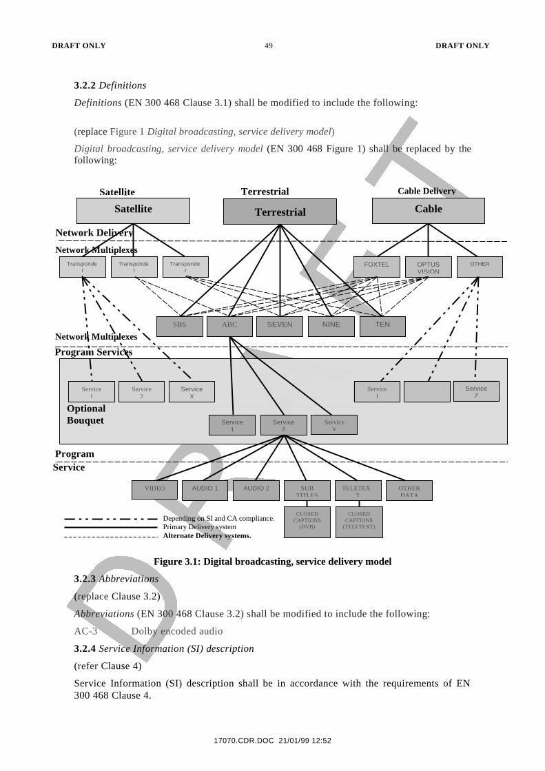
DRAFT ONLY 49 DRAFT ONLY
17070.CDR.DOC 21/01/99 12:52
3.2.2 Definitions
Definitions (EN 300 468 Clause 3.1) shall be modified to include the following:
(replace Figure 1 Digital broadcasting, service delivery model)
Digital broadcasting, service delivery model (EN 300 468 Figure 1) shall be replaced by thefollowing:
Figure 3.1: Digital broadcasting, service delivery model
3.2.3 Abbreviations
(replace Clause 3.2)
Abbreviations (EN 300 468 Clause 3.2) shall be modified to include the following:
AC-3 Dolby encoded audio
3.2.4 Service Information (SI) description
(refer Clause 4)
Service Information (SI) description shall be in accordance with the requirements of EN300 468 Clause 4.
OptionalBouquet
CableTerrestrialSatellite
FOXTEL OPTUSVISION
OTHER
ServiceZ
Service1
SEVEN NINE TENABCSBS
Service1
Service2
ServiceY
AUDIO 2 SUBTITLES
VIDEO TELETEXT
CLOSEDCAPTIONS
(TELETEXT)
Transponder
Transponder
Transponder
ServiceX
Service2
Service1
AUDIO 1 OTHERDATA
CLOSEDCAPTIONS
(DVB)
Satellite Terrestrial Cable Delivery
Network Delivery
Network Multiplexes
Network Multiplexes
Program Services
ProgramService
Depending on SI and CA compliance.Primary Delivery systemAlternate Delivery systems.
DRAFT ONLY 50 DRAFT ONLY
21/01/99 12:52
3.2.5 Service Information (SI) tables
(refer Clause 5)
Service Information (SI) tables shall be in accordance with the requirements of EN 300 468Clause 5.
3.2.6 SI table mechanism
(refer Clause 5.1)
SI table mechanism shall be in accordance with the requirements of EN 300 468 Clause 5.1.
3.2.7 Explanation
(refer Clause 5.1.1)
Explanation shall be in accordance with the requirements of EN 300 468 Clause 5.1.1.
3.2.8 Mapping of sections into Transport Stream (TS) packets
(refer Clause 5.1.2)
Mapping of sections into Transport Stream (TS) packets shall be in accordance with therequirements of EN 300 468 Clause 5.1.2.
3.2.9 Coding of PID and table_id fields*
(refer Clause 5.1.3*)
Coding of PID and table_id fields shall be in accordance with the requirements of EN 300468 Clause 5.1.3
3.2.10 Repetition rates and random access
(refer Clause 5.1.4)
Repetition rates and random access shall be in accordance with the requirements of EN 300468 Clause 5.1.4
3.2.11 Scrambling
(refer Clause 5.1.5)
Scrambling shall be in accordance with the requirements of EN 300 468 Clause 5.1.5.
3.2.12 Table definitions
(refer Clause 5.2)
Table definitions shall be in accordance with the requirements of EN 300 468 Clause 5.2.
3.2.13 Network Information Table (NIT)**
(replace Clause 5.2.1)
Network Information Table (NIT) shall be modified as follows:
Editor’s Note: The syntax of a transmitter-id descriptor should be included in the networkdescriptors loop of the Network Information Table.
The NIT (see table 3.1) conveys information relating to the physical organization of themultiplexes/TSs carried via a given network, and the characteristics of the network itself. Thecombination of original_network_id and transport_stream_id allow each TS to be uniquelyidentified throughout the ETS application area. Networks are assigned individual network_idvalues, which serve as unique identification codes for networks. The allocation of these codesmay be found in ETR 162 [6]. In the case that the NIT is transmitted on the network on whichthe TS was originated, the network_id and the original_network_id shall take the same value.
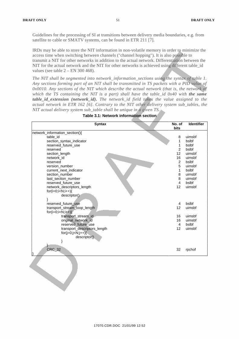
DRAFT ONLY 51 DRAFT ONLY
17070.CDR.DOC 21/01/99 12:52
Guidelines for the processing of SI at transitions between delivery media boundaries, e.g. fromsatellite to cable or SMATV systems, can be found in ETR 211 [7].
IRDs may be able to store the NIT information in non-volatile memory in order to minimize theaccess time when switching between channels ("channel hopping"). It is also possible totransmit a NIT for other networks in addition to the actual network. Differentiation between theNIT for the actual network and the NIT for other networks is achieved using different table_idvalues (see table 2 – EN 300 468).
The NIT shall be segmented into network_information_sections using the syntax of table 1.Any sections forming part of an NIT shall be transmitted in TS packets with a PID value of0x0010. Any sections of the NIT which describe the actual network (that is, the network ofwhich the TS containing the NIT is a part) shall have the table_id 0x40 with the sametable_id_extension (network_id). The network_id field takes the value assigned to theactual network in ETR 162 [6]. Contrary to the NIT other delivery system sub_tables, theNIT actual delivery system sub_table shall be unique in a given TS.
Table 3.1: Network information section
Syntax No. ofbits
Identifier
network_information_section(){table_id 8 uimsbfsection_syntax_indicator 1 bslbfreserved_future_use 1 bslbfreserved 2 bslbfsection_length 12 uimsbfnetwork_id 16 uimsbfreserved 2 bslbfversion_number 5 uimsbfcurrent_next_indicator 1 bslbfsection_number 8 uimsbflast_section_number 8 uimsbfreserved_future_use 4 bslbfnetwork_descriptors_length 12 uimsbffor(i=0;i<N;i++){
descriptor()}reserved_future_use 4 bslbftransport_stream_loop_length 12 uimsbffor(i=0;i<N;i++){
transport_stream_id 16 uimsbforiginal_network_id 16 uimsbfreserved_future_use 4 bslbftransport_descriptors_length 12 uimsbffor(j=0;j<N;j++){
descriptor()}
}CRC_32 32 rpchof
}
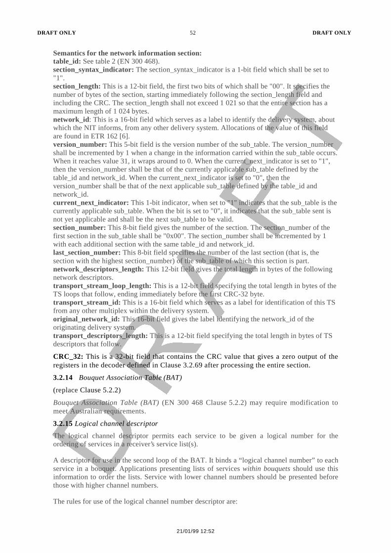
DRAFT ONLY 52 DRAFT ONLY
21/01/99 12:52
Semantics for the network information section:table_id: See table 2 (EN 300 468).section_syntax_indicator: The section_syntax_indicator is a 1-bit field which shall be set to"1".section_length: This is a 12-bit field, the first two bits of which shall be "00". It specifies thenumber of bytes of the section, starting immediately following the section_length field andincluding the CRC. The section_length shall not exceed 1 021 so that the entire section has amaximum length of 1 024 bytes.network_id: This is a 16-bit field which serves as a label to identify the delivery system, aboutwhich the NIT informs, from any other delivery system. Allocations of the value of this fieldare found in ETR 162 [6].version_number: This 5-bit field is the version number of the sub_table. The version_numbershall be incremented by 1 when a change in the information carried within the sub_table occurs.When it reaches value 31, it wraps around to 0. When the current_next_indicator is set to "1",then the version_number shall be that of the currently applicable sub_table defined by thetable_id and network_id. When the current_next_indicator is set to "0", then theversion_number shall be that of the next applicable sub_table defined by the table_id andnetwork_id.current_next_indicator: This 1-bit indicator, when set to "1" indicates that the sub_table is thecurrently applicable sub_table. When the bit is set to "0", it indicates that the sub_table sent isnot yet applicable and shall be the next sub_table to be valid.section_number: This 8-bit field gives the number of the section. The section_number of thefirst section in the sub_table shall be "0x00". The section_number shall be incremented by 1with each additional section with the same table_id and network_id.last_section_number: This 8-bit field specifies the number of the last section (that is, thesection with the highest section_number) of the sub_table of which this section is part.network_descriptors_length: This 12-bit field gives the total length in bytes of the followingnetwork descriptors.transport_stream_loop_length: This is a 12-bit field specifying the total length in bytes of theTS loops that follow, ending immediately before the first CRC-32 byte.transport_stream_id: This is a 16-bit field which serves as a label for identification of this TSfrom any other multiplex within the delivery system.original_network_id: This 16-bit field gives the label identifying the network_id of theoriginating delivery system.transport_descriptors_length: This is a 12-bit field specifying the total length in bytes of TSdescriptors that follow.
CRC_32: This is a 32-bit field that contains the CRC value that gives a zero output of theregisters in the decoder defined in Clause 3.2.69 after processing the entire section.
3.2.14 Bouquet Association Table (BAT)
(replace Clause 5.2.2)
Bouquet Association Table (BAT) (EN 300 468 Clause 5.2.2) may require modification tomeet Australian requirements.
3.2.15 Logical channel descriptor
The logical channel descriptor permits each service to be given a logical number for theordering of services in a receiver’s service list(s).
A descriptor for use in the second loop of the BAT. It binds a “logical channel number” to eachservice in a bouquet. Applications presenting lists of services within bouquets should use thisinformation to order the lists. Service with lower channel numbers should be presented beforethose with higher channel numbers.
The rules for use of the logical channel number descriptor are:
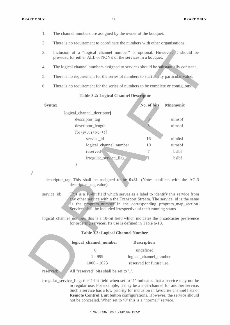
DRAFT ONLY 53 DRAFT ONLY
17070.CDR.DOC 21/01/99 12:52
1. The channel numbers are assigned by the owner of the bouquet.
2. There is no requirement to coordinate the numbers with other organisations.
3. Inclusion of a “logical channel number” is optional. However, it should beprovided for either ALL or NONE of the services in a bouquet.
4. The logical channel numbers assigned to services should be substantially constant.
5. There is no requirement for the series of numbers to start at any particular value.
6. There is no requirement for the series of numbers to be complete or contiguous.
Table 3.2: Logical Channel Descriptor
Syntax No. of bits Mnemonic
logical_channel_decriptor{
descriptor_tag 8 uimsbf
descriptor_length 8 uimsbf
for (i=0; i<N;++){
service_id 16 uimbsf
logical_channel_number 10 uimsbf
reserved 7 bslbf
irregular_service_flag 1 bslbf
}
}
descriptor_tag: This shall be assigned to be 0x81. (Note: conflicts with the AC-3descriptor _tag value)
service_id: This is a 16-bit field which serves as a label to identify this service fromany other service within the Transport Stream. The service_id is the sameas the program_number in the corresponding program_map_section.Services shall be included irrespective of their running status.
logical_channel_number: this is a 10-bit field which indicates the broadcaster preferencefor ordering services. Its use is defined in Table 6-10.
Table 3.3: Logical Channel Number
logical_channel_number Description
0 undefined
1 - 999 logical_channel_number
1000 - 1023 reserved for future use
reserved: All "reserved" bits shall be set to '1'.
irregular_service_flag: this 1-bit field when set to ‘1’ indicates that a service may not bein regular use. For example, it may be a side-channel for another service.Such a service has a low priority for inclusion in favourite channel lists orRemote Control Unit button configurations. However, the service shouldnot be concealed. When set to ‘0’ this is a “normal” service.
DRAFT ONLY 54 DRAFT ONLY
21/01/99 12:52
The logical channel descriptor may be inserted in the second descriptor loop of the BAT. Itshall be allowed only once in each loop.
It is not necessary that all service_ids referenced in the in the service_list_descriptor beallocated a logical channel number. The numbers used may start at any value, and need not becontiguous. The allocation of logical channel number to service within a sub-table should bequasi-static.
The logical_channel_number shall be unique across the bouquet if carried in the BAT forall services which the broadcaster wishes to be displayed separately. Where more than oneservice is assigned to the same logical_channel_number, only one service shall have therunning status of "running" at a time. The receiver may use the logical channel number fordefault service ordering, and assigning a number to the remote control for selection of thatservice.
3.2.16 Service Description Table (SDT)*
(replace Clause 5.2.3*)
Service Description Table (SDT) shall be modified as follows:
Each sub_table of the SDT (see table 3.4) shall describe services that are contained within aparticular TS. The services may be part of the actual TS or part of other TSs, these beingidentified by means of the table_id (see table 2 – EN 300 468).
The SDT shall be segmented into service_description_sections using the syntax of table 5.Any sections forming part of an SDT shall be transmitted in TS packets with a PID value of0x0011. Any sections of the SDT which describe the actual TS (that is, the TS containing theSDT) shall have the table_id 0x42, with the same table_id_extension(transport_stream_id) and with the same original_network_id (cf definition of an SDTsub_table). Any sections of an SDT which refer to a TS other than the actual TS shall take atable-id value of 0x46. Contrary to the SDT other transport stream sub_tables, the SDTactual transport stream sub_table shall be unique in a given TS.
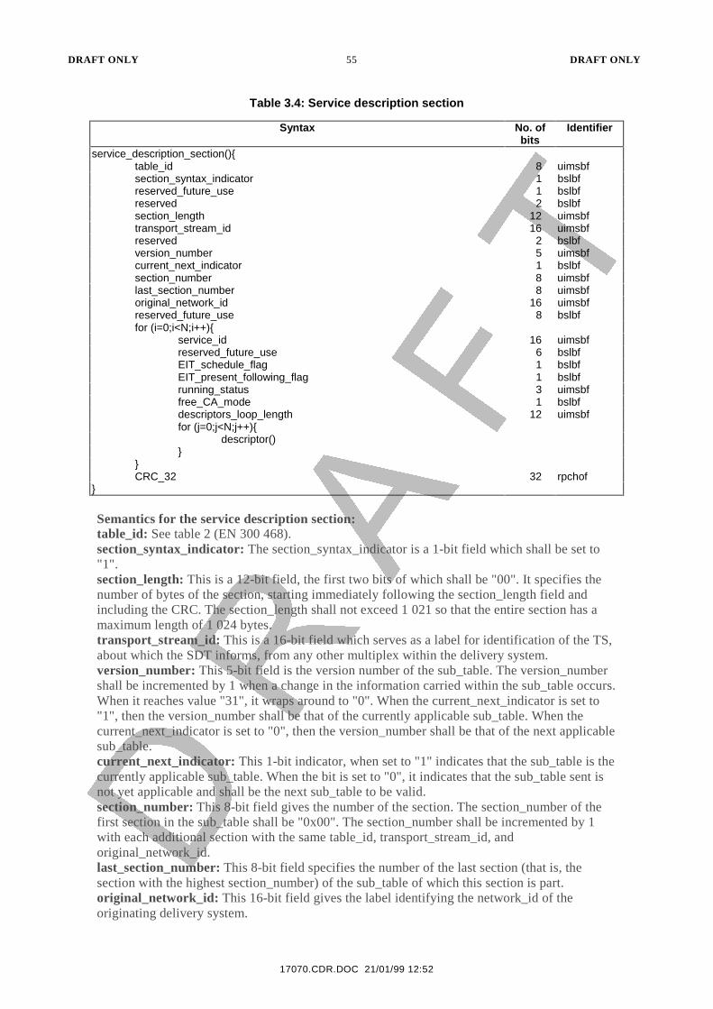
DRAFT ONLY 55 DRAFT ONLY
17070.CDR.DOC 21/01/99 12:52
Table 3.4: Service description section
Syntax No. ofbits
Identifier
service_description_section(){table_id 8 uimsbfsection_syntax_indicator 1 bslbfreserved_future_use 1 bslbfreserved 2 bslbfsection_length 12 uimsbftransport_stream_id 16 uimsbfreserved 2 bslbfversion_number 5 uimsbfcurrent_next_indicator 1 bslbfsection_number 8 uimsbflast_section_number 8 uimsbforiginal_network_id 16 uimsbfreserved_future_use 8 bslbffor (i=0;i<N;i++){
service_id 16 uimsbfreserved_future_use 6 bslbfEIT_schedule_flag 1 bslbfEIT_present_following_flag 1 bslbfrunning_status 3 uimsbffree_CA_mode 1 bslbfdescriptors_loop_length 12 uimsbffor (j=0;j<N;j++){
descriptor()}
}CRC_32 32 rpchof
}
Semantics for the service description section:table_id: See table 2 (EN 300 468).section_syntax_indicator: The section_syntax_indicator is a 1-bit field which shall be set to"1".section_length: This is a 12-bit field, the first two bits of which shall be "00". It specifies thenumber of bytes of the section, starting immediately following the section_length field andincluding the CRC. The section_length shall not exceed 1 021 so that the entire section has amaximum length of 1 024 bytes.transport_stream_id: This is a 16-bit field which serves as a label for identification of the TS,about which the SDT informs, from any other multiplex within the delivery system.version_number: This 5-bit field is the version number of the sub_table. The version_numbershall be incremented by 1 when a change in the information carried within the sub_table occurs.When it reaches value "31", it wraps around to "0". When the current_next_indicator is set to"1", then the version_number shall be that of the currently applicable sub_table. When thecurrent_next_indicator is set to "0", then the version_number shall be that of the next applicablesub_table.current_next_indicator: This 1-bit indicator, when set to "1" indicates that the sub_table is thecurrently applicable sub_table. When the bit is set to "0", it indicates that the sub_table sent isnot yet applicable and shall be the next sub_table to be valid.section_number: This 8-bit field gives the number of the section. The section_number of thefirst section in the sub_table shall be "0x00". The section_number shall be incremented by 1with each additional section with the same table_id, transport_stream_id, andoriginal_network_id.last_section_number: This 8-bit field specifies the number of the last section (that is, thesection with the highest section_number) of the sub_table of which this section is part.original_network_id: This 16-bit field gives the label identifying the network_id of theoriginating delivery system.
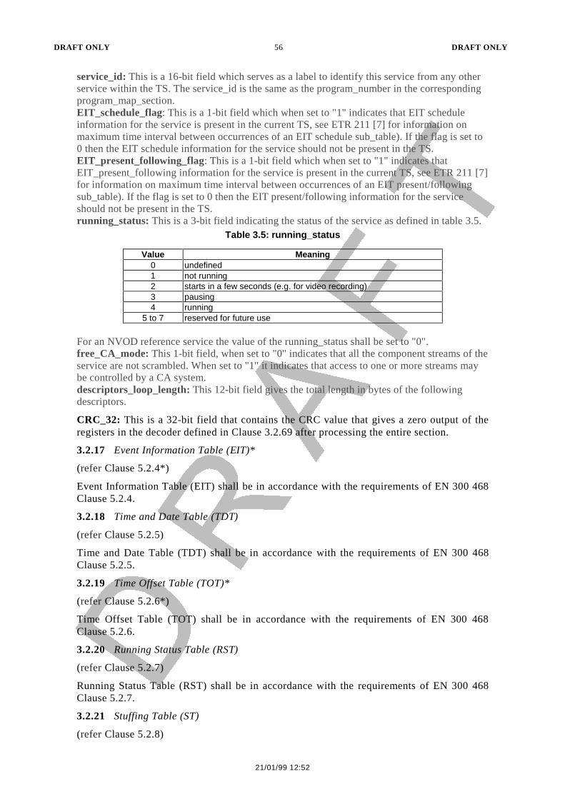
DRAFT ONLY 56 DRAFT ONLY
21/01/99 12:52
service_id: This is a 16-bit field which serves as a label to identify this service from any otherservice within the TS. The service_id is the same as the program_number in the correspondingprogram_map_section.EIT_schedule_flag: This is a 1-bit field which when set to "1" indicates that EIT scheduleinformation for the service is present in the current TS, see ETR 211 [7] for information onmaximum time interval between occurrences of an EIT schedule sub_table). If the flag is set to0 then the EIT schedule information for the service should not be present in the TS.EIT_present_following_flag: This is a 1-bit field which when set to "1" indicates thatEIT_present_following information for the service is present in the current TS, see ETR 211 [7]for information on maximum time interval between occurrences of an EIT present/followingsub_table). If the flag is set to 0 then the EIT present/following information for the serviceshould not be present in the TS.running_status: This is a 3-bit field indicating the status of the service as defined in table 3.5.
Table 3.5: running_status
Value Meaning0 undefined1 not running2 starts in a few seconds (e.g. for video recording)3 pausing4 running
5 to 7 reserved for future use
For an NVOD reference service the value of the running_status shall be set to "0".free_CA_mode: This 1-bit field, when set to "0" indicates that all the component streams of theservice are not scrambled. When set to "1" it indicates that access to one or more streams maybe controlled by a CA system.descriptors_loop_length: This 12-bit field gives the total length in bytes of the followingdescriptors.
CRC_32: This is a 32-bit field that contains the CRC value that gives a zero output of theregisters in the decoder defined in Clause 3.2.69 after processing the entire section.
3.2.17 Event Information Table (EIT)*
(refer Clause 5.2.4*)
Event Information Table (EIT) shall be in accordance with the requirements of EN 300 468Clause 5.2.4.
3.2.18 Time and Date Table (TDT)
(refer Clause 5.2.5)
Time and Date Table (TDT) shall be in accordance with the requirements of EN 300 468Clause 5.2.5.
3.2.19 Time Offset Table (TOT)*
(refer Clause 5.2.6*)
Time Offset Table (TOT) shall be in accordance with the requirements of EN 300 468Clause 5.2.6.
3.2.20 Running Status Table (RST)
(refer Clause 5.2.7)
Running Status Table (RST) shall be in accordance with the requirements of EN 300 468Clause 5.2.7.
3.2.21 Stuffing Table (ST)
(refer Clause 5.2.8)
DRAFT ONLY 57 DRAFT ONLY
17070.CDR.DOC 21/01/99 12:52
Stuffing Table (ST) shall be in accordance with the requirements of EN 300 468 Clause5.2.8.
3.2.22 Discontinuity Information Table (DIT)
(refer Clause 5.2.9)
Discontinuity Information Table (DIT) shall be in accordance with the requirements of EN300 468 Clause 5.2.9.
3.2.23 Selection Information Table (SIT)
(refer Clause 5.2.10)
Selection Information Table (SIT) shall be in accordance with the requirements of EN 300468 Clause 5.2.10.
3.2.24 Descriptors
(refer Clause 6)
Descriptors shall be in accordance with the requirements of EN 300 468 Clause 6.
3.2.25 Descriptor identification and location*
(replace Clause 6.1*)
Descriptor identification and location (EN 300 468 Clause 6.1) may require modification tomeet Australian requirements.
3.2.26 Descriptor coding *
(refer Clause 6.2*)
Descriptor coding shall be in accordance with the requirements of EN 300 468 Clause 6.2
3.2.27 Bouquet name descriptor
(refer Clause 6.2.1)
Bouquet name descriptor shall be in accordance with the requirements of EN 300 468Clause 6.2.1.
3.2.28 CA identifier descriptor
(refer Clause 6.2.2)
CA identifier descriptor shall be in accordance with the requirements of EN 300 468 Clause6.2.2.
3.2.29 Component descriptor*
(replace Clause 6.2.3*)
Component descriptor (EN 300 468 Clause 6.2.3) shall require modification to meetAustralian requirements. This modification will amend "Table 16: stream_content andcomponent_type", by adding values for the component_type field for AC-3 audio modesusing values from the DVB reserved values in the range 0x42 to 0xAF.
3.2.30 Content descriptor*
(replace Clause 6.2.4*)
Content descriptor (EN 300 468 Clause 6.2.4 shall require modification to meet Australianrequirements. This modification will amend "Table 18: Content_nibble level 1 and 2assignments", by modifying the description of level 1 (categories) and modifying thedescription of level 2 (content description) to suit Australian programming requirements.

DRAFT ONLY 58 DRAFT ONLY
21/01/99 12:52
3.2.31 Country availability descriptor
(refer Clause 6.2.5)
Country availability descriptor shall be in accordance with the requirements of EN 300 468Clause 6.2.5
3.2.32 Data broadcast descriptor*
(refer Clause 6.2.6*)
Data broadcast descriptor shall be in accordance with the requirements of EN 300 468Clause 6.2.6.
3.2.33 3.2.33 Data broadcast id descriptor*
(refer Clause 6.2.7*)
Data broadcast id descriptor shall be in accordance with the requirements of EN 300 468Clause 6.2.7.
3.2.34 Delivery system descriptors*
(refer Clause 6.2.8*)
Delivery system descriptors shall be in accordance with the requirements of EN 300 468Clause 6.2.8.
[Editor’s Note: 6.2.8.1 (Cable) and 6.2.8.2 (Satellite) not applicable.]
3.2.35 Terrestrial delivery system descriptor
(replace Clause 6.2.8.3)
Terrestrial delivery system descriptor (EN 300 468 Clause 6.2.8.3) may requiremodification to meet Australian requirements. This modification will assign a value toTable 30 for the 6 MHz bandwidth field of the terrestrial_system_delivery_descriptor whichdescribe the value assignments for the terrestrial television bandwidths applicable toAustralia.
Table 3.6: Signalling format for the bandwidth
bandwidth bandwidth value
000 8 MHz
001 7 MHz
010 6 MHz
011 to 111 reserved for future use
3.2.36 Extended event descriptor
(refer Clause 6.2.9)
Extended event descriptor shall be in accordance with the requirements of EN 300 468Clause 6.2.9.
3.2.37 Frequency list descriptor*
(refer Clause 6.2.10*)
Frequency list descriptor (EN 300 468 Clause 6.2.10) shall be in accordance with therequirements of EN 300 468 Clause 6.2.10
Editor’s Note: This clause does not require modification unless offset values are requiredfor Australian Band IV and Band V operation. No offset is required for Band III operation.
DRAFT ONLY 59 DRAFT ONLY
17070.CDR.DOC 21/01/99 12:52
3.2.38 Linkage descriptor*
(refer Clause 6.2.11*)
Linkage descriptor shall be in accordance with the requirements of EN 300 468 Clause6.2.11
3.2.39 Local time offset descriptor*
(refer Clause 6.2.12*)
Local time offset descriptor shall be in accordance with the requirements of EN 300 468Clause 6.2.12
Editor’s Note: The local time offset descriptor may be used in the TOT to describe countryspecific dynamic changes of the local time offset relative to UTC. Table 42 identifies the codingof country_region_id. This may require modification to meet Australian requirements.
3.2.40 Mosaic descriptor*
(refer Clause 6.2.13*)
Mosaic descriptor shall be in accordance with the requirements of EN 300 468 Clause6.2.13.
3.2.41 Multilingual bouquet name descriptor
(refer Clause 6.2.14)
Multilingual bouquet name descriptor shall be in accordance with the requirements of EN300 468 Clause 6.2.14.
3.2.42 Multilingual component descriptor
(refer Clause 6.2.15)
Multilingual component descriptor shall be in accordance with the requirements of EN 300468 Clause 6.2.15.
3.2.43 Multilingual network name descriptor
(refer Clause 6.2.16)
Multilingual network name descriptor shall be in accordance with the requirements of EN300 468 Clause 6.2.16.
3.2.44 Multilingual service name descriptor
(refer Clause 6.2.17)
Multilingual service name descriptor shall be in accordance with the requirements of EN300 468 Clause 6.2.17.
3.2.45 Near Video On Demand (NVOD) reference descriptor
(refer Clause 6.2.18)
Near Video On Demand (NVOD) reference descriptor shall be in accordance with therequirements of EN 300 468 Clause 6.2.18.
3.2.46 Network name descriptor
(refer Clause 6.2.19)
Network name descriptor shall be in accordance with the requirements of EN 300 468Clause 6.2.19.
3.2.47 Parental rating descriptor
(replace Clause 6.2.20)
DRAFT ONLY 60 DRAFT ONLY
21/01/99 12:52
Parental rating descriptor (EN 300 468 Clause 6.2.20) may require modification to meetAustralian requirements.
3.2.48 Partial Transport Stream (TS) descriptor
(refer Clause 6.2.21)
Partial Transport Stream (TS) descriptor shall be in accordance with the requirements of EN300 468 Clause 6.2.21
3.2.49 Private data specifier descriptor
(replace Clause 6.2.22)
Private data specifier descriptor (EN 300 468 Clause 6.2.20) may require modification tomeet Australian requirements.
3.2.50 Short smoothing buffer descriptor
(refer Clause 6.2.23)
Short smoothing buffer descriptor shall be in accordance with the requirements of EN 300468 Clause 6.2.23.
3.2.51 Service descriptor*
(refer Clause 6.2.24*)
Service descriptor shall be in accordance with the requirements of EN 300 468 Clause6.2.24.
3.2.52 Service list descriptor*
(refer Clause 6.2.25*)
Service list descriptor shall be in accordance with the requirements of EN 300 468 Clause6.2.25.
3.2.53 Service move descriptor
(refer Clause 6.2.26)
Service move descriptor shall be in accordance with the requirements of EN 300 468 Clause6.2.26.
3.2.54 Short event descriptor
(refer Clause 6.2.27)
Short event descriptor shall be in accordance with the requirements of EN 300 468 Clause6.2.27.
3.2.55 Stream identifier descriptor
(refer Clause 6.2.28)
Stream identifier descriptor shall be in accordance with the requirements of EN 300 468Clause 6.2.28.
3.2.56 Stuffing descriptor
(refer Clause 6.2.29)
Stuffing descriptor shall be in accordance with the requirements of EN 300 468 Clause6.2.29.
3.2.57 Subtitling descriptor
(refer Clause 6.2.30)
DRAFT ONLY 61 DRAFT ONLY
17070.CDR.DOC 21/01/99 12:52
Subtitling descriptor shall be in accordance with the requirements of EN 300 468 Clause6.2.30.
3.2.58 Telephone descriptor*
(refer Clause 6.2.31*)
Telephone descriptor shall be in accordance with the requirements of EN 300 468 Clause6.2.31.
3.2.59 Teletext descriptor*
(refer Clause 6.2.32*)
Teletext descriptor shall be in accordance with the requirements of EN 300 468 Clause6.2.32.
3.2.60 Time shifted event descriptor
(refer Clause 6.2.33)
Time shifted event descriptor shall be in accordance with the requirements of EN 300 468Clause 6.2.33.
3.2.61 Time shifted service descriptor
(refer Clause 6.2.34)
Time shifted service descriptor shall be in accordance with the requirements of EN 300 468Clause 6.2.34.
3.2.62 Storage Media Interoperability (SMI) measures
(refer Clause 7)
Storage Media Interoperability (SMI) measures shall be in accordance with therequirements of EN 300 468 Clause 7
3.2.63 SMI tables
(refer Clause 7.1)
SMI tables shall be in accordance with the requirements of EN 300 468 Clause 7.1
3.2.64 Discontinuity Information Table (DIT)
(refer Clause 7.1.1)
Discontinuity Information Table (DIT) shall be in accordance with the requirements of EN300 468 Clause 7.1.1
3.2.65 Selection Information Table (SIT)
(refer Clause 7.1.2)
Selection Information Table (SIT) shall be in accordance with the requirements of EN 300468 Clause 7.1.2
3.2.66 SMI descriptors
(refer Clause 7.2)
SMI descriptors shall be in accordance with the requirements of EN 300 468 Clause 7.2
3.2.67 Partial Transport Stream (TS) descriptor
(refer Clause 7.2.1)
Partial Transport Stream (TS) descriptor shall be in accordance with the requirements of EN300 468 Clause 7.2.1
DRAFT ONLY 62 DRAFT ONLY
21/01/99 12:52
3.2.68 Annex A (normative): Coding of text characters
(refer Annex A)
Annex A (normative): Coding of text characters shall be in accordance with therequirements of EN 300 468.
3.2.69 Annex B (normative): CRC decoder model
(refer Annex B)
Annex B (normative): CRC decoder model shall be in accordance with the requirements ofEN 300 468.
3.2.70 Annex C (informative): Conversion between time and date conventions
(refer Annex C)
Annex C (informative): conversion between time and date conventions shall be inaccordance with the requirements of EN 300 468.
3.3 Implementation and usage of Service Information (Reference ETR 211 DigitalVideo Broadcasting (DVB);Guidelines on implementation and usage of ServiceInformation (SI))
3.3.1 Service Information (SI) table information
(replace Clause 4.1)
Service Information (SI) table information (ETR 211 Clause 4.1) may require modificationto meet Australian requirements.
3.3.2 Network Information Table (NIT) information
(replace Clause 4.1.1)
Network Information Table (NIT) information (ETR 211 Clause 4.1) may requiremodification to meet Australian requirements.
3.3.3 Bouquet Association Table (BAT) information
(replace Clause 4.1.2)
Bouquet Association Table (BAT) (ETR 211 Clause 4.1.2) may require modification to meetAustralian requirements.
3.3.4 Service Description Table (SDT) information
(replace Clause 4.1.3)
Service Description Table (SDT) information (ETR 211 Clause 4.1.3) may requiremodification to meet Australian requirements.
3.3.5 Event Information Table (EIT) information
(refer Clause 4.1.4)
Event Information Table (EIT) information shall be in accordance with the requirements ofETR 211 Clause 4.1.4
3.3.6 EIT Present/Following information
(refer Clause 4.1.4.1)
EIT Present/Following information shall be in accordance with the requirements of ETR211 Clause 4.1.4.1.
3.3.7 EIT Schedule information
(refer Clause 4.1.4.2)
DRAFT ONLY 63 DRAFT ONLY
17070.CDR.DOC 21/01/99 12:52
EIT Schedule information shall be in accordance with the requirements of ETR 211 Clause4.1.4.2
3.3.8 EIT Schedule structure
(refer Clause 4.1.4.2)
Schedule structure shall be in accordance with the requirements of ETR 211 Clause4.1.4.2.1
3.3.9 EIT scrambling
(refer Clause 4.1.4.2.2)
EIT scrambling shall be in accordance with the requirements of ETR 211 Clause 4.1.4.2.2.
3.3.10 Time and Date Table (TDT)
(refer Clause 4.1.5)
Time and Date Table (TDT) shall be in accordance with the requirements of ETR 211Clause 4.1.5.
3.3.11 Time Offset Table (TOT)
(refer Clause 4.1.6)
Time Offset Table (TOT) shall be in accordance with the requirements of ETR 211 Clause4.1.6
3.3.12 Running Status Table (RST)
(refer Clause 4.1.7)
Running Status Table (RST) shall be in accordance with the requirements of ETR 211Clause 4.1.7
3.3.13 Stuffing Table (ST)
(refer Clause 4.1.8)
Stuffing Table (ST) shall be in accordance with the requirements of ETR 211 Clause 4.1.8.
3.3.14 Table update mechanism
(refer Clause 4.1.9)
Table update mechanism shall be in accordance with the requirements of ETR 211 Clause4.1.9.
3.3.15 SI descriptor allocation and usage
(refer Clause 4.2)
SI descriptor allocation and usage shall be in accordance with the requirements of ETR 211Clause 4.2.
3.3.16 Descriptors of the Network Information Table (NIT)
(replace Clause 4.2.1)
Descriptors of the Network Information Table (NIT) (ETR 211 Clause 4.2.1) may requiremodification to meet Australian requirements.
3.3.17 First descriptor loop
(refer Clause 4.2.1.1)
First descriptor loop shall be in accordance with the requirements of ETR 211 Clause4.2.1.1.
DRAFT ONLY 64 DRAFT ONLY
21/01/99 12:52
3.3.18 Linkage descriptor
(refer Clause 4.2.1.1.1)
Linkage descriptor shall be in accordance with the requirements of ETR 211 Clause4.2.1.1.1
3.3.19 Multilingual network name descriptor
(refer Clause 4.2.1.1.2)
Multilingual network name descriptor shall be in accordance with the requirements of ETR211 Clause 4.2.1.1.2.
3.3.20 Network name descriptor
(refer Clause 4.2.1.1.3)
Network name descriptor shall be in accordance with the requirements of ETR 211Clause 4.2.1.1.3.
3.3.21 Second descriptor loop
(refer Clause 4.2.1.2)
Second descriptor loop shall be in accordance with the requirements of ETR 211 Clause4.2.1.2.
3.3.22 Delivery system descriptors*
(refer Clause 4.2.1.2.1*)
Delivery system descriptors shall be in accordance with the requirements of ETR 211Clause 4.2.1.2.1
3.3.23 Service list descriptor*
(refer Clause 4.2.1.2.2*)
Service list descriptor shall be in accordance with the requirements of ETR 211 Clause4.2.1.2.2.
3.3.24 Frequency list descriptor
(replace Clause 4.2.1.2.3)
Frequency list descriptor (ETR 211 Clause 4.2.1.2.3) may require modification to meetAustralian requirements.
3.3.25 Descriptors of the Bouquet Association Table (BAT)
(replace Clause 4.2.2)
Descriptors of the Bouquet Association Table (BAT) (ETR 211 Clause 4.2.2) may requiremodification to meet Australian requirements.
3.3.26 First descriptor loop
(refer Clause 4.2.2.1)
First descriptor loop shall be in accordance with the requirements of ETR 211 Clause4.2.2.1
3.3.27 Bouquet name descriptor
(refer Clause 4.2.2.1.1)
Bouquet name descriptor shall be in accordance with the requirements of ETR 211 Clause4.2.2.1.1
DRAFT ONLY 65 DRAFT ONLY
17070.CDR.DOC 21/01/99 12:52
3.3.28 CA identifier descriptor
(refer Clause 4.2.2.1.2)
CA identifier descriptor shall be in accordance with the requirements of ETR 211 Clause4.2.2.1.2
3.3.29 Country availability descriptor
(refer Clause 4.2.2.1.3)
Country availability descriptor shall be in accordance with the requirements of ETR 211Clause 4.2.2.1.3
3.3.30 Linkage descriptor
(refer Clause 4.2.2.1.4)
Linkage descriptor shall be in accordance with the requirements of ETR 211 Clause4.2.2.1.4
3.3.31 Multilingual bouquet name descriptor
(refer Clause 4.2.2.1.5)
Multilingual bouquet name descriptor shall be in accordance with the requirements of ETR211 Clause 4.2.2.1.5
3.3.32 Second descriptor loop
(refer Clause 4.2.2.2)
Second descriptor loop shall be in accordance with the requirements of ETR 211 Clause4.2.2.2
3.3.33 Service list descriptor
(refer Clause 4.2.2.2.1)
Service list descriptor shall be in accordance with the requirements of ETR 211 Clause4.2.2.2.1.
3.3.34 Descriptors of the Service Description Table (SDT)
(replace Clause 4.2.3)
Descriptors of the Service Description Table (SDT) (ETR 211 Clause 4.2.3) may requiremodification to meet Australian requirements.
3.3.35 Bouquet name descriptor
(refer Clause 4.2.3.1)
Bouquet name descriptor shall be in accordance with the requirements of ETR 211 Clause4.2.3.1
3.3.36 CA identifier descriptor
(refer Clause 4.2.3.2)
CA identifier descriptor shall be in accordance with the requirements of ETR 211 Clause4.2.3.2
3.3.37 Country availability descriptor
(refer Clause 4.2.3.3)
Country availability descriptor shall be in accordance with the requirements of ETR 211Clause 4.2.3.3
DRAFT ONLY 66 DRAFT ONLY
21/01/99 12:52
3.3.38 Data_broadcast_descriptor
(refer Clause 4.2.3.4)
Data_broadcast_descriptor shall be in accordance with the requirements of ETR 211 Clause4.2.3.4.
3.3.39 Linkage descriptor
(refer Clause 4.2.3.5)
Linkage descriptor shall be in accordance with the requirements of ETR 211 Clause 4.2.3.5
3.3.40 Mosaic descriptor
(refer Clause 4.2.3.6)
Mosaic descriptor shall be in accordance with the requirements of ETR 211 Clause 4.2.3.6.
3.3.41 Multilingual service descriptor
(refer Clause 4.2.3.7)
Multilingual service descriptor shall be in accordance with the requirements of ETR 211Clause 4.2.3.7.
3.3.42 NVOD reference descriptor
(refer Clause 4.2.3.8)
NVOD reference descriptor shall be in accordance with the requirements of ETR 211Clause 4.2.3.8
3.3.43 Service descriptor
(refer Clause 4.2.3.9)
Service descriptor shall be in accordance with the requirements of ETR 211 Clause 4.2.3.9.
3.3.44 Telephone descriptor
(refer Clause 4.2.3.10)
Telephone descriptor shall be in accordance with the requirements of ETR 211 Clause4.2.3.10.
3.3.45 Time shifted service descriptor
(refer Clause 4.2.3.11)
Time shifted service descriptor shall be in accordance with the requirements of ETR 211Clause 4.2.3.11
3.3.46 Descriptors of the Event Information Table (EIT)
(refer Clause 4.2.4)
Descriptors of the Event Information Table (EIT) shall be in accordance with therequirements of ETR 211 Clause 4.2.4
3.3.47 Component descriptor
(refer Clause 4.2.4.1)
Component descriptor shall be in accordance with the requirements of ETR 211 Clause4.2.4.1
3.3.48 Content descriptor*
(refer Clause 4.2.4.2*)
Content descriptor shall be in accordance with the requirements of ETR 211 Clause 4.2.4.2.
DRAFT ONLY 67 DRAFT ONLY
17070.CDR.DOC 21/01/99 12:52
3.3.49 Data_broadcast_descriptor
(refer Clause 4.2.4.3)
Data_broadcast_descriptor shall be in accordance with the requirements of ETR 211 Clause4.2.4.3
3.3.50 Extended event descriptor
(refer Clause 4.2.4.4)
Extended event descriptor shall be in accordance with the requirements of ETR 211 Clause4.2.4.4
3.3.51 Linkage descriptor
(refer Clause 4.2.4.5)
Linkage descriptor shall be in accordance with the requirements of ETR 211 Clause 4.2.4.5
3.3.52 Multilingual component descriptor
(refer Clause 4.2.4.6)
Multilingual component descriptor shall be in accordance with the requirements of ETR 211Clause 4.2.4.6
3.3.53 Parental rating descriptor
(replace Clause 4.2.4.7)
Parental rating descriptor (ETR 211 Clause 4.2.7.7) may require modification to meetAustralian requirements.
3.3.54 Short event descriptor
(refer Clause 4.2.4.8)
Short event descriptor shall be in accordance with the requirements of ETR 211 Clause4.2.4.8.
3.3.55 Telephone descriptor
(refer Clause 4.2.4.9)
Telephone descriptor shall be in accordance with the requirements of ETR 211 Clause4.2.4.9.
3.3.56 Time shifted event descriptor
(refer Clause 4.2.4.10)
Time shifted event descriptor shall be in accordance with the requirements of ETR 211Clause 4.2.4.10
3.3.57 Descriptors of the Time Offset Table (TOT)
(refer Clause 4.2.5)
Descriptors of the Time Offset Table (TOT) shall be in accordance with the requirements ofETR 211 Clause 4.2.5
3.3.58 Local time offset descriptor
(refer Clause 4.2.5.1)
Local time offset shall be in accordance with the requirements of ETR 211 Clause 4.2.5.1
3.3.59 Descriptors of the Program Map Table (PMT)
(refer Clause 4.2.6)
DRAFT ONLY 68 DRAFT ONLY
21/01/99 12:52
Descriptors of the Program Map Table (PMT) shall be in accordance with the requirementsof ETR 211 Clause 4.2.6
3.3.60 Mosaic descriptor
(refer Clause 4.2.6.1)
Mosaic descriptor shall be in accordance with the requirements of ETR 211 Clause 4.2.6.1.
3.3.61 Service move descriptor
(refer Clause 4.2.6.2)
Service move descriptor shall be in accordance with the requirements of ETR 211 Clause4.2.6.2.
3.3.62 Stream identifier descriptor
(refer Clause 4.2.6.3)
Stream identifier descriptor shall be in accordance with the requirements of ETR 211Clause 4.2.6.3.
3.3.63 Teletext descriptor
(refer Clause 4.2.6.4)
Teletext descriptor shall be in accordance with the requirements of ETR 211 Clause 4.2.6.4.
3.3.64 Other descriptors
(refer Clause 4.2.7)
Other descriptors shall be in accordance with the requirements of ETR 211 Clause 4.2.7
3.3.65 Private data specifier descriptor
(refer Clause 4.2.7.1)
Private data specifier descriptor shall be in accordance with the requirements of ETR 211Clause 4.2.7.1
3.3.66 Stuffing descriptor
(refer Clause 4.2.7.2)
Stuffing descriptor shall be in accordance with the requirements of ETR 211 Clause 4.2.7.2.
3.3.67 Data_broadcast_descriptor*
(refer Clause 4.2.7.3*)
Data_broadcast_descriptor shall be in accordance with the requirements of ETR 211 Clause4.2.7.3
3.3.68 ISO13818-1 descriptors*
(refer Clause 4.2.8*)
ISO 13818-1 (AS/NZS 13818.1:1997) descriptors shall be in accordance with therequirements of ETR 211 Clause 4.2.8.
3.3.69 Unknown descriptors
(refer Clause 4.2.9)
Unknown descriptors shall be in accordance with the requirements of ETR 211 Clause 4.2.9
3.3.70 Program Specific Information (PSI) and DVB SI operational interaction states
(refer Clause 4.3)
DRAFT ONLY 69 DRAFT ONLY
17070.CDR.DOC 21/01/99 12:52
Program Specific Information (PSI) and DVB SI operational interaction states shall be inaccordance with the requirements of ETR 211 Clause 4.3
3.3.71 Minimum repetition rates
(refer Clause 4.4)
Minimum repetition rates shall be in accordance with the requirements of ETR 211 Clause4.4
3.3.72 Satellite and cable delivery systems
(refer Clause 4.4.1)
Satellite and cable delivery systems shall be in accordance with the requirements of ETR211 Clause 4.4.1
3.3.73 Terrestrial delivery systems
(refer Clause 4.4.2)
Terrestrial delivery systems shall be in accordance with the requirements of ETR 211Clause 4.4.2
3.3.74 Terrestrial systems
(refer Clause 4.5)
Terrestrial systems shall be in accordance with the requirements of ETR 211 Clause 4.5
3.3.75 Terms used within terrestrial systems
(refer Clause 4.5.1)
Terms used within terrestrial systems shall be in accordance with the requirements of ETR211 Clause 4.5.1
3.3.76 The use of alternative frequencies for multiplexes
(refer Clause 4.5.2)
The use of alternative frequencies for multiplexes shall be in accordance with therequirements of ETR 211 Clause 4.5.2
3.3.77 Regional or local services
(refer Clause 4.5.3)
Regional or local services shall be in accordance with the requirements of ETR 211 Clause4.5.3
3.3.78 Text string formatting
(refer Clause 4.6)
Test string formatting shall be in accordance with the requirements of ETR 211 Clause 4.6.
3.3.79 Use of control codes in names
(refer Clause 4.6.1)
Use of control codes in names shall be in accordance with the requirements of ETR 211Clause 4.6.1.
3.3.80 Use of control codes in text
(refer Clause 4.6.2)
Use of control codes in text shall be in accordance with the requirements of ETR 211Clause 4.6.2.
DRAFT ONLY 70 DRAFT ONLY
21/01/99 12:52
3.3.81 Applications
(refer Clause 5)
Applications shall be in accordance with the requirements of ETR 211 Clause 5
3.3.82 NVOD services
(refer Clause 5.1)
NVOD services shall be in accordance with the requirements of ETR 211 Clause 5.1
3.3.83 Mosaic services
(refer Clause 5.2)
Mosaic services shall be in accordance with the requirements of ETR 211 Clause 5.2
3.3.84 General considerations
(refer Clause 5.2.1)
General considerations shall be in accordance with the requirements of ETR 211 Clause5.2.1
3.3.85 Relationship between mosaic service and SI/PSI Tables
(refer Clause 5.2.2)
Relationship between mosaic service and SI/PSI Tables shall be in accordance with therequirements of ETR 211 Clause 5.2.2
3.3.86 Transitions at broadcast delivery media boundaries
(refer Clause 5.3)
Transitions at broadcast delivery media boundaries shall be in accordance with therequirements of ETR 211 Clause 5.3
3.3.87 Seamless transitions
(refer Clause 5.3.1)
Seamless transitions shall be in accordance with the requirements of ETR 211 Clause 5.3.1
3.3.88 Non-seamless transitions without re-multiplexing
(refer Clause 5.3.2)
Non–seamless transitions without re–multiplexing shall be in accordance with therequirements of ETR 211 Clause 5.3.2
3.3.89 Transitions with re-multiplexing
(refer Clause 5.3.3)
Transitions with re–multiplexing shall be in accordance with the requirements of ETR 211Clause 5.3.3
3.3.90 Storage media
(refer Clause 6)
Storage media shall be in accordance with the requirements of ETR 211 Clause 6
3.3.91 Program Association Table (PAT)
(refer Clause 6.1)
Program Association Table (PAT) shall be in accordance with the requirements of ETR 211Clause 6.1
DRAFT ONLY 71 DRAFT ONLY
17070.CDR.DOC 21/01/99 12:52
3.3.92 Program Map Table (PMT)
(refer Clause 6.2)
Program Map Table (PMT) shall be in accordance with the requirements of ETR 211 Clause6.2
3.3.93 SI tables (NIT, SDT, EIT, BAT, RST, TDT, TOT)
(refer Clause 6.3)
SI tables (NIT, SDT, EIT, BAT, RST, TDT, TOT) shall be in accordance with therequirements of ETR 211 Clause 6.3
3.3.94 Selection Information Table (SIT)
(refer Clause 6.4)
Selection Information Table (SIT) shall be in accordance with the requirements of ETR 211Clause 6.4
3.3.95 Discontinuity Information Table (DIT)
(refer Clause 6.5)
Discontinuity Information Table (DIT) shall be in accordance with the requirements of ETR211 Clause 6.5
3.3.96 Annex A (informative): Inter-operation with ATSC Systems
(refer Annex A)
Annex A (informative): Inter-operation with ATSC Systems shall be in accordance with therequirements of ETR 211
3.4 Allocation of Service Information (SI) codes (refer ETR 162 Digital broadcastingsystems for television, sound and data services; Allocation of Service Information (SI)codes for Digital Video Broadcasting (DVB) systems)*
3.4.1 Allocation of Service Information (SI) codes.
Editor’s Note: Future versions of this Australian standard will address the modificationsrequired to ETSI Technical Report ETR 162 to meet Australian requirements.
ETSI Technical Report ETR 162 supplements ETSI standard ETS 300 468. ETR 162identifies the SI codes allocated for DVB systems. The following codes are identified;
the Original_network_id and the network_id used to identify a network;.
the Bouquet_id used to identify a bouquet;
the CA_system_id used to identify the kind of encryption used;
the Country code used to identify a country or region;
the Private_data_specifier values used to identify private service information.
These tables of DVB registered values of Service Information Codes will be referenced bythe Australian Standard to maintain national and international co-ordination of these values.
Australia will apply for registration of it's Original_network_id's, Network_id's,Bouquet_id's (where applicable) and CA_system_id's.

DRAFT ONLY 72 DRAFT ONLY
21/01/99 12:52
4 ELEMENTARY STREAM VIDEO
4.1 Elementary stream video
(refer AS/NZS 13818-2 Information technology – Generic coding of moving picturesand associated audio information Part 2: Video)
4.2 Scope
(refer Clause 1 )
Scope shall be in accordance with the requirements of AS/NZS 13818-2 Clause 1
4.3 Normative References
(refer Clause 2)
Normative References shall be in accordance with the requirements of AS/NZS 13818-2Clause 2
4.4 Definitions
(refer Clause 3)
Definitions shall be in accordance with the requirements of AS/NZS 13818-2 Clause 3
4.5 Abbreviations and Symbols
(refer Clause 4)
Abbreviations and Symbols shall be in accordance with the requirements of AS/NZS 13818-2 Clause 4
4.6 Arithmetic operators
(refer Clause 4.1 )
Arithmetic operators shall be in accordance with the requirements of AS/NZS 13818-2Clause 4.1
4.7 Logical Operators
(refer Clause 4.2)
Logical Operators shall be in accordance with the requirements of AS/NZS 13818-2 Clause4.2
4.8 Relational operators
(refer Clause 4.3)
Relational operators shall be in accordance with the requirements of AS/NZS 13818-2Clause 4.3
4.9 Bitwise operators
(refer Clause 4.4)
Bitwise operators shall be in accordance with the requirements of AS/NZS 13818-2 Clause4.4

DRAFT ONLY 73 DRAFT ONLY
17070.CDR.DOC 21/01/99 12:52
4.10 Assignment
(refer Clause 4.5)
Assignment shall be in accordance with the requirements of AS/NZS 13818-2 Clause 4.5
4.11 Mnemonics
(refer Clause 4.6)
Mnemonics shall be in accordance with the requirements of AS/NZS 13818-2 Clause 4.6
4.12 Constants
(refer Clause 4.7)
Constants shall be in accordance with the requirements of AS/NZS 13818-2 Clause 4.7
4.13 Conventions
(refer Clause 5)
Conventions shall be in accordance with the requirements of AS/NZS 13818-2 Clause 5
4.14 Method of describing bitstream syntax
(refer Clause 5.1)
Method of describing bitstream syntax shall be in accordance with the requirements ofAS/NZS 13818-2 Clause 5.1
4.15 Definition of functions
(refer Clause 5.2)
Definition of functions shall be in accordance with the requirements of AS/NZS 13818-2Clause 5.2
4.16 Reserved, forbidden and marker bit
(refer Clause 5.3)
Reserved, forbidden and marker bit shall be in accordance with the requirements ofAS/NZS 13818-2 Clause 5.3
4.17 Arithmetic precision
(refer Clause 5.4)
Arithmetic precision shall be in accordance with the requirements of AS/NZS 13818-2Clause 5.4
4.18 Video Bitstream syntax and semantics
(refer Clause 6)
Video Bitstream syntax and semantics shall be in accordance with the requirements ofAS/NZS 13818-2 Clause 6
4.19 Structure of coded video data
(refer Clause 6.1)
DRAFT ONLY 74 DRAFT ONLY
21/01/99 12:52
Structure of coded video data shall be in accordance with the requirements of AS/NZS13818-2 Clause 6.1
4.20 Video bitstream syntax
(refer Clause 6.2)
Video bitstream syntax shall be in accordance with the requirements of AS/NZS 13818-2Clause 6.2
4.21 Video bitstream semantics
(refer Clause 6.3)
Video bitstream semantics shall be in accordance with the requirements of AS/NZS 13818-2 Clause 6.3
4.22 The Video Decoding process
(refer Clause 7)
The Video Decoding process shall be in accordance with the requirements of AS/NZS13818-2 Clause 7
4.23 Higher syntactic structures
(refer Clause 7.1)
Higher syntactic structures shall be in accordance with the requirements of AS/NZS 13818-2 Clause 7.1
4.24 Variable length coding
(refer Clause 7.2)
Variable length coding shall be in accordance with the requirements of AS/NZS 13818-2Clause 7.2
4.25 Inverse scan
(refer Clause 7.3)
Inverse scan shall be in accordance with the requirements of AS/NZS 13818-2 Clause 7.3
4.26 Inverse quantisation
(refer Clause 7.4)
Inverse quantisation shall be in accordance with the requirements of AS/NZS 13818-2 Clause7.4
4.27 Inverse DCT
(refer Clause 7.5)
Inverse DCT shall be in accordance with the requirements of AS/NZS 13818-2 Clause 7.5
DRAFT ONLY 75 DRAFT ONLY
17070.CDR.DOC 21/01/99 12:52
4.28 Motion compensation
(refer Clause 7.6)
Motion compensation shall be in accordance with the requirements of AS/NZS 13818-2Clause 7.6
4.29 Spatial scalability
(refer Clause 7.7)
Spatial scalability shall be in accordance with the requirements of AS/NZS 13818-2 Clause7.7
4.30 SNR scalability
(refer Clause 7.8)
SNR scalability shall be in accordance with the requirements of AS/NZS 13818-2 Clause7.8
4.31 Temporal scalability
(refer Clause 7.9)
Temporal scalability shall be in accordance with the requirements of AS/NZS 13818-2Clause 7.9
4.32 Data partitioning
(refer Clause 7.10)
Data partitioning shall be in accordance with the requirements of AS/NZS 13818-2 Clause7.10
4.33 Hybrid scalability
(refer Clause 7.11)
Hybrid scalability shall be in accordance with the requirements of AS/NZS 13818-2 Clause7.11
4.34 Output of the decoding process
(refer Clause 7.12)
Output of the decoding process shall be in accordance with the requirements of AS/NZS13818-2 Clause 7.12
4.35 Profiles and Levels
(refer Clause 8)
Profiles and Levels shall be in accordance with the requirements of AS/NZS 13818-2Clause 8
4.36 ISO/IEC 11172-2 compatibility
(refer Clause 8.1)
ISO/IEC 11172-2 compatibility shall be in accordance with the requirements of AS/NZS13818-2 Clause 8.1
DRAFT ONLY 76 DRAFT ONLY
21/01/99 12:52
4.37 Relationship between the defined profiles
(refer Clause 8.2)
Relationship between the defined profiles shall be in accordance with the requirements ofAS/NZS 13818-2 Clause 8.2
4.38 Relationship between the defined levels
(refer Clause 8.3)
Relationship between the defined levels shall be in accordance with the requirements ofAS/NZS 13818-2 Clause 8.3
4.39 Scalable layers
(refer Clause 8.4)
Scalable layers shall be in accordance with the requirements of AS/NZS 13818-2 Clause 8.4
4.40 Parameter values for defined profiles, levels and layers
(refer Clause 8.5)
Parameter values for defined profiles, levels and layers shall be in accordance with therequirements of AS/NZS 13818-2 Clause 8.5
4.41 Discrete cosine transform
(refer Annex A)
Discrete cosine transform shall be in accordance with the requirements of AS/NZS 13818-2Annex A
4.42 Variable length code tables
(refer Annex B)
Variable length code tables shall be in accordance with the requirements of AS/NZS 13818-2 Annex B
4.43 Macroblock addressing
(refer Annex B.1)
Macroblock addressing shall be in accordance with the requirements of AS/NZS 13818-2Annex B.1
4.44 Macroblock type
(refer Annex B.2)
Macroblock type shall be in accordance with the requirements of AS/NZS 13818-2 AnnexB.2
4.45 Macroblock pattern
(refer Annex B.3)
Macroblock pattern shall be in accordance with the requirements of AS/NZS 13818-2Annex B.3

DRAFT ONLY 77 DRAFT ONLY
17070.CDR.DOC 21/01/99 12:52
4.46 Motion vectors
(refer Annex B.4)
Motion vectors shall be in accordance with the requirements of AS/NZS 13818-2 AnnexB.4
4.47 DCT coefficients
(refer Annex B.5)
DCT coefficients shall be in accordance with the requirements of AS/NZS 13818-2 AnnexB.5
4.48 Video buffering verifier
(refer Annex C)
Video buffering verifier shall be in accordance with the requirements of AS/NZS 13818-2Annex C
4.49 Features supported by the algorithm
(refer Annex D)
Features supported by the algorithm shall be in accordance with the requirements ofAS/NZS 13818-2 Annex D
4.50 Overview
(refer Annex D.1)
Overview shall be in accordance with the requirements of AS/NZS 13818-2 Annex D.1
4.51 Video formats
(refer Annex D.2)
Video formats shall be in accordance with the requirements of AS/NZS 13818-2 Annex D.2
4.52 Picture quality
(refer Annex D.3)
Picture quality shall be in accordance with the requirements of AS/NZS 13818-2 Annex D.3
4.53 Data rate control
(refer Annex D.4)
Data rate control shall be in accordance with the requirements of AS/NZS 13818-2 AnnexD.4
4.54 Low delay mode
(refer Annex D.5)
Low delay mode shall be in accordance with the requirements of AS/NZS 13818-2 AnnexD.5
4.55 Random access/channel hopping
(refer Annex D.6)
DRAFT ONLY 78 DRAFT ONLY
21/01/99 12:52
Random access/channel hopping shall be in accordance with the requirements of AS/NZS13818-2 Annex D.6
4.56 Scalability
(refer Annex D.7)
Scalability shall be in accordance with the requirements of AS/NZS 13818-2 Annex D.7
4.57 Compatibility
(refer Annex D.8)
Compatibility shall be in accordance with the requirements of AS/NZS 13818-2 Annex D.8
4.58 Differences between this specification and ISO/IEC 111172-2
(refer Annex D.9)
Differences between this specification and ISO/IEC 111172-2 shall be in accordance withthe requirements of AS/NZS 13818-2 Annex D.9
4.59 Complexity
(refer Annex D.10)
Complexity shall be in accordance with the requirements of AS/NZS 13818-2 Annex D.10
4.60 Editing encoded bitstreams
(refer Annex D.11)
Editing encoded bitstreams shall be in accordance with the requirements of AS/NZS 13818-2 Annex D.11
4.61 Trick modes
(refer Annex D.12)
Trick modes shall be in accordance with the requirements of AS/NZS 13818-2 Annex D.12
4.62 Error resilience
(refer Annex D.13)
Error resilience shall be in accordance with the requirements of AS/NZS 13818-2 AnnexD.13
4.63 Concatenated sequences
(refer Annex D.14)
Concatenated sequences shall be in accordance with the requirements of AS/NZS 13818-2Annex D.14
4.64 Profile and Level restrictions
(refer Annex E)
Profile and Level restrictions shall be in accordance with the requirements of AS/NZS13818-2 Annex E
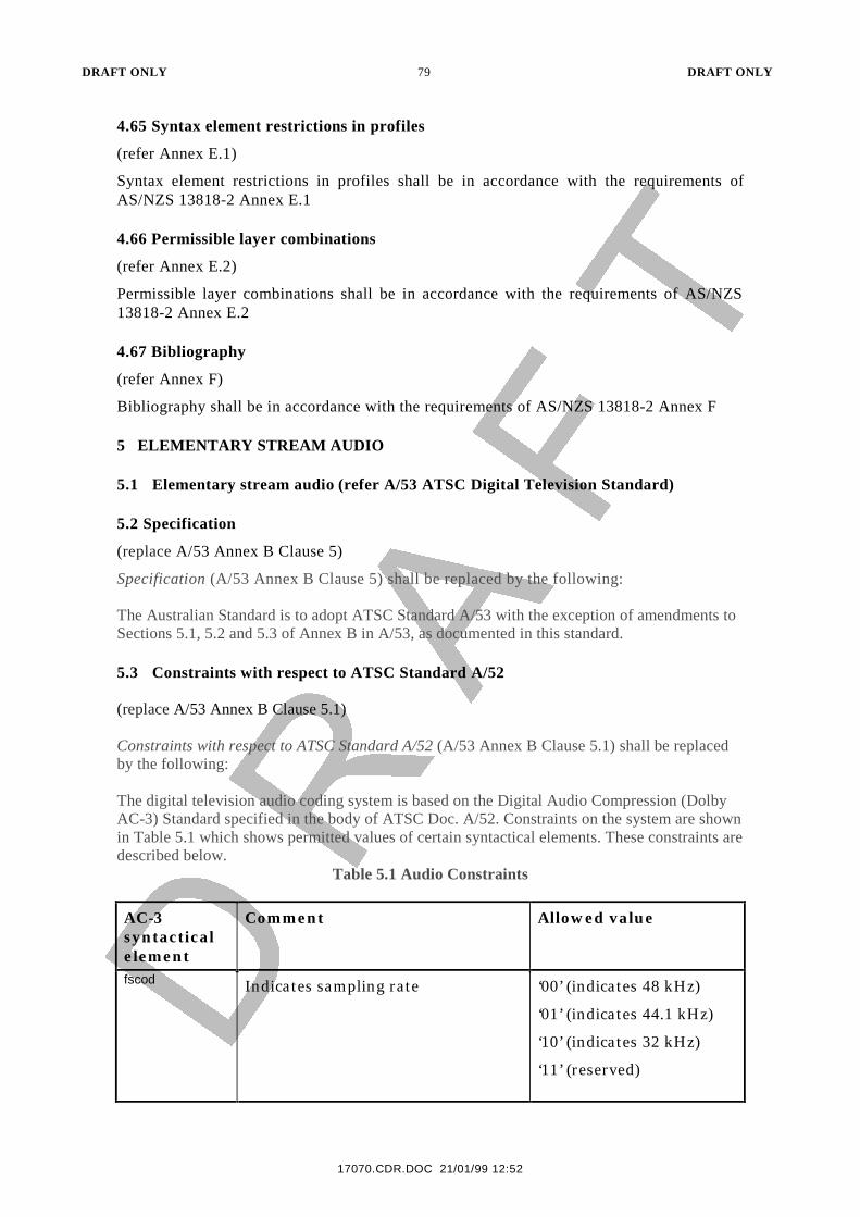
DRAFT ONLY 79 DRAFT ONLY
17070.CDR.DOC 21/01/99 12:52
4.65 Syntax element restrictions in profiles
(refer Annex E.1)
Syntax element restrictions in profiles shall be in accordance with the requirements ofAS/NZS 13818-2 Annex E.1
4.66 Permissible layer combinations
(refer Annex E.2)
Permissible layer combinations shall be in accordance with the requirements of AS/NZS13818-2 Annex E.2
4.67 Bibliography
(refer Annex F)
Bibliography shall be in accordance with the requirements of AS/NZS 13818-2 Annex F
5 ELEMENTARY STREAM AUDIO
5.1 Elementary stream audio (refer A/53 ATSC Digital Television Standard)
5.2 Specification
(replace A/53 Annex B Clause 5)
Specification (A/53 Annex B Clause 5) shall be replaced by the following:
The Australian Standard is to adopt ATSC Standard A/53 with the exception of amendments toSections 5.1, 5.2 and 5.3 of Annex B in A/53, as documented in this standard.
5.3 Constraints with respect to ATSC Standard A/52
(replace A/53 Annex B Clause 5.1)
Constraints with respect to ATSC Standard A/52 (A/53 Annex B Clause 5.1) shall be replacedby the following:
The digital television audio coding system is based on the Digital Audio Compression (DolbyAC-3) Standard specified in the body of ATSC Doc. A/52. Constraints on the system are shownin Table 5.1 which shows permitted values of certain syntactical elements. These constraints aredescribed below.
Table 5.1 Audio Constraints
AC-3syntacticalelement
Comment Allowed value
fscod Indicates sampling rate ‘00’ (indicates 48 kHz)
‘01’ (indicates 44.1 kHz)
‘10’ (indicates 32 kHz)
‘11’ (reserved)
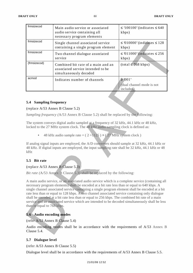
DRAFT ONLY 80 DRAFT ONLY
21/01/99 12:52
frmsizecod Main audio service or associatedaudio service containing allnecessary program elements
≤ ‘100100’ (indicates ≤ 640kbps)
frmsizecod Single channel associated servicecontaining a single program element
≤ ‘010000’ (indicates ≤ 128kbps)
frmsizecod Two channel dialogue associatedservice
≤ ‘011000’ (indicates ≤ 256kbps)
(frmsizecod) Combined bit rate of a main and anassociated service intended to besimultaneously decoded
(total ≤ 768 kbps)
acmod Indicates number of channels ≥ ‘001’(dual channel mode is notincluded)
5.4 Sampling frequency
(replace A/53 Annex B Clause 5.2)
Sampling frequency (A/53 Annex B Clause 5.2) shall be replaced by the following:
The system conveys digital audio sampled at a frequency of 32 kHz, 44.1 kHz or 48 kHz,locked to the 27 MHz system clock. The 48 kHz audio sampling clock is defined as:
• 48 kHz audio sample rate = ( 2 ÷1125 ) × ( 27 MHz system clock )
If analog signal inputs are employed, the A/D converters should sample at 32 kHz, 44.1 kHz or48 kHz. If digital inputs are employed, the input sampling rate shall be 32 kHz, 44.1 kHz or 48kHz
5.5 Bit rate
(replace A/53 Annex B Clause 5.3)
Bit rate (A/53 Annex B Clause 5.3) shall be replaced by the following:
A main audio service, or an associated audio service which is a complete service (containing allnecessary program elements) shall be encoded at a bit rate less than or equal to 640 kbps. Asingle channel associated service containing a single program element shall be encoded at a bitrate less than or equal to 128 kbps. A two channel associated service containing only dialogueshall be encoded at a bit rate less than or equal to 256 kbps. The combined bit rate of a mainservice and an associated service which are intended to be decoded simultaneously shall be lessthan or equal to 768 kbps.
5.6 Audio encoding modes
(refer A/53 Annex B Clause 5.4)
Audio encoding modes shall be in accordance with the requirements of A/53 Annex BClause 5.4.
5.7 Dialogue level
(refer A/53 Annex B Clause 5.5)
Dialogue level shall be in accordance with the requirements of A/53 Annex B Clause 5.5.
DRAFT ONLY 81 DRAFT ONLY
17070.CDR.DOC 21/01/99 12:52
5.8 Dynamic range compression
(refer A/53 Annex B Clause 5.6)
Dynamic range compression shall be in accordance with the requirements of A/53 Annex BClause 5.6.
5.9 Main and associated services
(refer A/53 Annex B Clause 6)
Main and associated services shall be in accordance with the requirements of A/53 Annex BClause 5.5
5.10 Audio Encoder Interfaces
(refer A/53 Annex B Clause 7)
Audio Encoder Interfaces shall be in accordance with the requirements of ATSC A/53Clause 7.
6 DATA BROADCASTING
6.1 Data broadcasting (refer EN 301 192 Digital Video Broadcasting (DVB); DVBspecification for data broadcasting*)
6.1.1 Data piping
(refer Clause 4)
Data piping shall be in accordance with the requirements of EN 301 192 Clause 4.
6.1.2 Data transport specification
(refer Clause 4.1)
Data transport specification shall be in accordance with the requirements of EN 301 192Clause 4.1.
6.1.3 PSI and SI specifications
(refer Clause 4.2)
PSI and SI specifications shall be in accordance with the requirements of EN 301 192Clause 4.2.
6.1.4 Data_broadcast_descriptor
(refer Clause 4.2.1)
Data_broadcast_descriptor shall be in accordance with the requirements of EN 301 192Clause 4.2.1.
6.1.5 Stream type
(refer Clause 4.2.2)
Stream type shall be in accordance with the requirements of EN 301 192 Clause 4.2.2.
6.1.6 Asynchronous data streaming
(refer Clause 5)
Asynchronous data streaming shall be in accordance with the requirements of EN 301 192Clause 5.
DRAFT ONLY 82 DRAFT ONLY
21/01/99 12:52
6.1.7 Data transport specification
(refer Clause 5.1)
Data transport specification shall be in accordance with the requirements of EN 301 192Clause 5.1.
6.1.8 PSI and SI specifications
(refer Clause 5.2)
PSI and SI specifications shall be in accordance with the requirements of EN 301 192Clause 5.2.
6.1.9 Data_broadcast_descriptor
(refer Clause 5.2.1)
Data_broadcast_descriptor shall be in accordance with the requirements of EN 301 192Clause 5.2.1.
6.1.10 Stream type
(refer Clause 5.2.2)
Stream type shall be in accordance with the requirements of EN 301 192 Clause 5.2.2.
6.1.11 Synchronous and synchronized data streaming
(refer Clause 6)
Synchronous and synchronized data streaming shall be in accordance with the requirementsof EN 301 192 Clause 6.
6.1.12 Data transport specification
(refer Clause 6.1)
Data transport specification shall be in accordance with the requirements of EN 301 192Clause 6.1.
6.1.13 PSI and SI specifications
(refer Clause 6.2)
PSI and SI specification shall be in accordance with the requirements of EN 301 192Clause 6.2.
6.1.14 Data_broadcast_descriptor
(refer Clause 6.2.1)
Data_broadcast_descriptor shall be in accordance with the requirements of EN 301 192Clause 6.2.1.
6.1.15 Stream type
(refer Clause 6.2.2)
Stream type shall be in accordance with the requirements of EN 301 192 Clause 6.2.2.
6.1.16 Multiprotocol encapsulation
(refer Clause 7)
Multiprotocol encapsulation shall be in accordance with the requirements of EN 301 192Clause 7.
6.1.17 Data transport specification
(refer Clause 7.1)
DRAFT ONLY 83 DRAFT ONLY
17070.CDR.DOC 21/01/99 12:52
Data transport specification shall be in accordance with the requirements of EN 301 192Clause 7.1.
6.1.18 PSI and SI specifications
(refer Clause 7.2)
PSI and SI specification shall be in accordance with the requirements of EN 301 192Clause 7.2.
6.1.19 Data_broadcast_descriptor
(refer Clause 7.2.1)
Data_broadcast_descriptor shall be in accordance with the requirements of EN 301 192Clause 7.2.1.
6.1.20 Stream type
(refer Clause 7.2.2)
Stream type shall be in accordance with the requirements of EN 301 192 Clause 7.2.2.
6.1.21 Data carousels
(refer Clause 8)
Data carousels shall be in accordance with the requirements of EN 301 192 Clause 8.
6.1.22 Data transport specification
(refer Clause 8.1)
Data transport specification shall be in accordance with the requirements of EN 301 192Clause 8.1.
6.1.23 Structure of DVB data carousel
(refer Clause 8.1.1)
Structure of DVB data carousel shall be in accordance with the requirements of EN 301 192Clause 8.1.1.
6.1.24 DownloadServerInitiate message
(refer Clause 8.1.2)
DownloadServerInitiate message shall be in accordance with the requirements ofEN 301 192 Clause 8.1.2.
6.1.25 DownloadInfoIndication message
(refer Clause 8.1.3)
DownloadInfoIndication message shall be in accordance with the requirements ofEN 301 192 Clause 8.1.3.
6.1.26 DownloadDataBlock message
(refer Clause 8.1.4)
DownloadDataBlock message shall be in accordance with the requirements of EN 301 192Clause 8.1.4.
6.1.27 DownloadCancel
(refer Clause 8.1.5)
DownloadCancel shall be in accordance with the requirements of EN 301 192 Clause 8.1.5.
DRAFT ONLY 84 DRAFT ONLY
21/01/99 12:52
6.1.28 Descriptors
(refer Clause 8.2)
Descriptors shall be in accordance with the requirements of EN 301 192 Clause 8.2.
6.1.29 Descriptor identification and location
(refer Clause 8.2.1)
Descriptor identification and location shall be in accordance with the requirements ofEN 301 192 Clause 8.2.1.
6.1.30 Type descriptor
(refer Clause 8.2.2)
Type descriptor shall be in accordance with the requirements of EN 301 192 Clause 8.2.2.
6.1.31 Name descriptor
(refer Clause 8.2.3)
Name descriptor shall be in accordance with the requirements of EN 301 192 Clause 8.2.3.
6.1.32 Info descriptor
(refer Clause 8.2.4)
Info descriptor shall be in accordance with the requirements of EN 301 192 Clause 8.2.4.
6.1.33 Module link descriptor
(refer Clause 8.2.5)
Module link descriptor shall be in accordance with the requirements of EN 301 192Clause 8.2.5.
6.1.34 CRC32 descriptor
(refer Clause 8.2.6)
CRC32 descriptor shall be in accordance with the requirements of EN 301 192 Clause 8.2.6.
6.1.35 Location descriptor
(refer Clause 8.2.7)
Location descriptor shall be in accordance with the requirements of EN 301 192Clause 8.2.7.
6.1.36 Estimated download time descriptor
(refer Clause 8.2.8)
Estimated download time descriptor shall be in accordance with the requirements ofEN 301 192 Clause 8.2.8.
6.1.37 Group link descriptor
(refer Clause 8.2.9)
Group link descriptor shall be in accordance with the requirements of EN 301 192Clause 8.2.9.
6.1.38 Private descriptor
(refer Clause 8.2.10)
Private descriptor shall be in accordance with the requirements of EN 301 192Clause 8.2.10.
DRAFT ONLY 85 DRAFT ONLY
17070.CDR.DOC 21/01/99 12:52
6.1.39 PSI and SI specifications
(refer Clause 8.3)
PSI and SI specifications shall be in accordance with the requirements of EN 301 192Clause 8.3.
6.1.40 Data_broadcast_descriptor
(refer Clause 8.3.1)
Data_broadcast_descriptor shall be in accordance with the requirements of EN 301 192Clause 8.3.1.
6.1.41 Stream type
(refer Clause 8.3.2)
Stream type shall be in accordance with the requirements of EN 301 192 Clause 8.3.2.
6.1.42 Object carousels
(refer Clause 9)
Object carousels shall be in accordance with the requirements of EN 301 192 Clause 9.
6.1.43 Scope of the object carousels
(refer Clause 9.1)
Scope of the object carousels shall be in accordance with the requirements of EN 301 192Clause 9.1.
6.1.44 Data transport specification
(refer Clause 9.2)
Data transport specifications shall be in accordance with the requirements of EN 301 192Clause 9.2.
6.1.45 Carousel NSAP address
(refer Clause 9.2.1)
Carousel NSAP address shall be in accordance with the requirements of EN 301 192Clause 9.2.1.
6.1.46 PSI and SI specifications
(refer Clause 9.3)
PSI and SI specifications shall be in accordance with the requirements of EN 301 192Clause 9.3.
6.1.47 Data_broadcast_descriptor
(refer Clause 9.3.1)
Data_broadcast_descriptor shall be in accordance with the requirements of EN 301 192Clause 9.3.1.
6.1.48 Deferred_association_tags_descriptor
(refer Clause 9.3.2)
Deferred_association_tags_descriptor shall be in accordance with the requirements ofEN 301 192 Clause 9.3.2.
6.1.49 Stream type
(refer Clause 9.3.3)
DRAFT ONLY 86 DRAFT ONLY
21/01/99 12:52
Stream type shall be in accordance with the requirements of EN 301 192 Clause 9.3.3.
6.1.50 Decoder models
(refer Clause 10)
Decoder models shall be in accordance with the requirements of EN 301 192 Clause 10.
6.1.51 Annex A (informative): Registration of private data broadcast systems
(refer Annex A)
Annex A (informative): Registration of private data broadcast systems shall be inaccordance with the requirements of EN 301 192.
6.2 Subtitling ( Reference ETS 300 743 Digital Video Broadcasting (DVB); Subtitlingsystems)
6.2.1 Subtitle decoder model
(refer Clause 5)
Subtitle decoder model shall be in accordance with the requirements of ETS 300 743Clause 5.
6.2.2 Decoder temporal model
(refer Clause 5.1)
Decoder temporal model shall be in accordance with the requirements of ETS 300 743Clause 5.1.
6.2.3 Service acquisition
(refer Clause 5.1.1)
Service acquisition shall be in accordance with the requirements of ETS 300 743Clause 5.1.1.
6.2.4 Presentation Time Stamps (PTS)
(refer Clause 5.1.2)
Presentation Time Stamps (PTS) shall be in accordance with the requirements ofETS 300 743 Clause 5.1.2.
6.2.5 Page composition
(refer Clause 5.1.3)
Page composition shall be in accordance with the requirements of ETS 300 743Clause 5.1.3.
6.2.6 Region composition
(refer Clause 5.1.4)
Region composition shall be in accordance with the requirements of ETS 300 743Clause 5.1.4.
6.2.7 Points to note
(refer Clause 5.1.5)
Points to note shall be in accordance with the requirements of ETS 300 743 Clause 5.1.5.
6.2.8 Buffer memory model
(refer Clause 5.2)
DRAFT ONLY 87 DRAFT ONLY
17070.CDR.DOC 21/01/99 12:52
Buffer memory model shall be in accordance with the requirements of ETS 300 743Clause 5.2.
6.2.9 Pixel display buffer memory
(refer Clause 5.2.1)
Pixel display buffer memory shall be in accordance with the requirements of ETS 300 743Clause 5.2.1.
6.2.10 Region memory
(refer Clause 5.2.2)
Region memory shall be in accordance with the requirements of ETS 300 743 Clause 5.2.2.
6.2.11 Composition buffer memory
(refer Clause 5.2.3)
Composition buffer memory shall be in accordance with the requirements of ETS 300 743Clause 5.2.3.
6.2.12 Cumulative display construction
(refer Clause 5.3)
Cumulative display construction shall be in accordance with the requirements ofETS 300 743 Clause 5.3.
6.2.13 Decoder rendering bandwidth model
(refer Clause 5.4)
Decoder rendering bandwidth model shall be in accordance with the requirements ofETS 300 743 Clause 5.4.
6.2.14 Page erasure
(refer Clause 5.4.1)
Page erasure shall be in accordance with the requirements of ETS 300 743 Clause 5.4.1.
6.2.15 Region move or change in visibility
(refer Clause 5.4.2)
Region move or change in visibility shall be in accordance with the requirements ofETS 300 743 Clause 5.4.2.
6.2.16 Region fill
(refer Clause 5.4.3)
Region fill shall be in accordance with the requirements of ETS 300 743 Clause 5.4.3.
6.2.17 CLUT modification
(refer Clause 5.4.4)
CLUT modification shall be in accordance with the requirements of ETS 300 743Clause 5.4.4.
6.2.18 Graphic object decoding
(refer Clause 5.4.5)
Graphic object decoding shall be in accordance with the requirements of ETS 300 743Clause 5.4.5.

DRAFT ONLY 88 DRAFT ONLY
21/01/99 12:52
6.2.19 Character object decoding
(refer Clause 5.4.6)
Character object decoding shall be in accordance with the requirements of ETS 300 743Clause 5.4.6.
6.2.20 PES packet format
(refer Clause 6)
PES packet format shall be in accordance with the requirements of ETS 300 743 Clause 6.
6.2.21 The PES packet data for subtitling
(refer Clause 7)
The PES packet data for subtitling shall be in accordance with the requirements ofETS 300 743 Clause 7.
6.2.22 Syntax and semantics of the PES data field for subtitling
(refer Clause 7.1)
Syntax and semantics of the PES data field for subtitling shall be in accordance with therequirements of ETS 300 743 Clause 7.1.
6.2.23 Syntax and semantics of the subtitling segment
(refer Clause 7.2)
Syntax and semantics of the subtitling segment shall be in accordance with the requirementsof ETS 300 743 Clause 7.2.
6.2.24 Page composition segment
(refer Clause 7.2.1)
Page composition segment shall be in accordance with the requirements of ETS 300 743Clause 7.2.1.
6.2.25 Region composition segment
(refer Clause 7.2.2)
Region composition segment shall be in accordance with the requirements of ETS 300 743Clause 7.2.2.
6.2.26 CLUT definition segment
(refer Clause 7.2.3)
CLUT definition segment shall be in accordance with the requirements of ETS 300 743Clause 7.2.3.
6.2.27 Object data segment
(refer Clause 7.2.4)
Object data segment shall be in accordance with the requirements of ETS 300 743Clause 7.2.4.
6.2.28 Pixel-data sub-block
(refer Clause 7.2.4.1)
Pixel-data sub-block shall be in accordance with the requirements of ETS 300 743Clause 7.2.4.1.
6.2.29 Syntax and semantics of the pixel code strings
(refer Clause 7.2.4.2)
DRAFT ONLY 89 DRAFT ONLY
17070.CDR.DOC 21/01/99 12:52
Syntax and semantics of the pixel code strings shall be in accordance with the requirementsof ETS 300 743 Clause 7.2.4.2.
6.2.30 Requirements for the subtitling data
(refer Clause 8)
Requirements for the subtitling data shall be in accordance with the requirements ofETS 300 743 Clause 8.
6.2.31 Scope of Identifiers
(refer Clause 8.1)
Scope of Identifiers shall be in accordance with the requirements of ETS 300 743Clause 8.1.
6.2.32 Scope of dependencies
(refer Clause 8.2)
Scope of dependencies shall be in accordance with the requirements of ETS 300 743Clause 8.2.
6.2.33 Composition page
(refer Clause 8.2.1)
Composition page shall be in accordance with the requirements of ETS 300 743Clause 8.2.1.
6.2.34 Ancillary page
(refer Clause 8.2.2)
Ancillary page shall be in accordance with the requirements of ETS 300 743 Clause 8.2.2.
6.2.35 Order of delivery
(refer Clause 8.3)
Order of delivery shall be in accordance with the requirements of ETS 300 743 Clause 8.3.
6.2.36 PTS field
(refer Clause 8.3.1)
PTS field shall be in accordance with the requirements of ETS 300 743 Clause 8.3.1.
6.2.37 Positioning of regions and objects
(refer Clause 8.4)
Positioning of regions and objects shall be in accordance with the requirements ofETS 300 743 Clause 8.4.
6.2.38 Regions
(refer Clause 8.4.1)
Regions shall be in accordance with the requirements of ETS 300 743 Clause 8.4.1.
6.2.39 Objects sharing a PTS
(refer Clause 8.4.2)
Objects sharing a PTS shall be in accordance with the requirements of ETS 300 743Clause 8.4.2.
6.2.40 Objects added to a region
(refer Clause 8.4.3)
DRAFT ONLY 90 DRAFT ONLY
21/01/99 12:52
Objects added to a region shall be in accordance with the requirements of ETS 300 743Clause 8.4.3.
6.2.41 Avoiding excess pixel-data capacity
(refer Clause 8.5)
Avoiding excess pixel-data capacity shall be in accordance with the requirements ofETS 300 743 Clause 8.5.
6.2.42 Translation to colour components
(refer Clause 9)
Translation to colour components shall be in accordance with the requirements ofETS 300 743 Clause 9.
6.2.43 4- to 2-bit reduction
(refer Clause 9.1)
4- to 2-bit reduction shall be in accordance with the requirements of ETS 300 743Clause 9.1.
6.2.44 8- to 2-bit reduction
(refer Clause 9.2)
8- to 2-bit reduction shall be in accordance with the requirements of ETS 300 743Clause 9.2.
6.2.45 8- to 4-bit reduction
(refer Clause 9.3)
8- to 4-bit reduction shall be in accordance with the requirements of ETS 300 743Clause 9.3.
6.2.46 Default CLUTs and map-tables contents
(refer Clause 10)
Defult CLUTs and map-tables contents shall be in accordance with the requirements ofETS 300 743 Clause 10.
6.2.47 256-entry CLUT default contents
(refer Clause 10.1)
256-entry CLUT default contents shall be in accordance with the requirements ofETS 300 743 Clause 10.1.
6.2.48 16-entry CLUT default contents
(refer Clause 10.2)
16-entry CLUT default contents shall be in accordance with the requirements ofETS 300 743 Clause 10.2.
6.2.49 4-entry CLUT default contents
(refer Clause 10.3)
4-entry CLUT default contents shall be in accordance with the requirements ofETS 300 743 Clause 10.3.
6.2.50 2_to_4-bit_map-table default contents
(refer Clause 10.4)
DRAFT ONLY 91 DRAFT ONLY
17070.CDR.DOC 21/01/99 12:52
2_to_4-bit_map-table default contents shall be in accordance with the requirements ofETS 300 743 Clause 10.4.
6.2.51 2_to_8-bit_map-table default contents
(refer Clause 10.5)
2_to_8-bit_map-table default contents shall be in accordance with the requirements ofETS 300 743 Clause 10.5.
6.2.52 4_to_8-bit_map-table default contents
(refer Clause 10.6)
4_to_8-bit_map-table default contents shall be in accordance with the requirements ofETS 300 743 Clause 10.6.
6.2.53 Structure of the pixel code strings (informative)
(refer Clause 11)
Structure of the pixel code strings (informative) shall be in accordance with therequirements of ETS 300 743 Clause 11.
6.2.54 Annex A (informative):How the DVB subtitling system works
(refer Annex A)
Annex A (informative) : How the DVCB subtitling systems works shall be in accordancewith the requirements of ETS 300 743.
6.3 Conveying ITU-R System B Teletext (refer EN 300 472 Digital VideoBroadcasting (DVB); Specification for conveying ITU-R System B Teletext in DVBbitstreams
6.3.1 Insertion of Teletext into the MPEG-2 transport multiplex
(refer Clause 4)
Insertion of Teletext into the MPEG-2 transport multiplex shall be in accordance with therequirements of EN 300 472 Clause 4.
6.3.2 Transport Stream (TS) packet format
(refer Clause 4.1)
Transport Stream (TS) packet format shall be in accordance with the requirements of EN300 472 Clause 4.1.
6.3.3 PES packet format
(refer Clause 4.2)
PES packet format shall be in accordance with the requirements of EN 300 472 Clause 4.2.
6.3.4 Syntax for PES data field
(refer Clause 4.3)
Syntax for PES data field shall be in accordance with the requirements of EN 300 472Clause 4.3.
6.3.5 Semantics for PES data field
(refer Clause 4.4)
Semantics for PES data field shall be in accordance with the requirements of EN 300 472Clause 4.4.
DRAFT ONLY 92 DRAFT ONLY
21/01/99 12:52
6.3.6 Teletext decoder model
(refer Clause 5)
Teletext decoder model shall be in accordance with the requirements of EN 300 472Clause 5.
7 CONDITIONAL ACCESS
7.1 Conditional Access (refer ETR 289 Digital Video Broadcasting (DVB); Supportfor use of scrambling and Conditional Access (CA) within digital broadcastingsystems)
7.1.1 The DVB Scrambling Algorithm
(refer Clause 4)
The DVB Scrambling Algorithm shall be in accordance with the requirements of ETR 289Clause 4.
7.1.2 The DVB Scrambling Algorithm custodian
(refer Clause 4.1)
The DVB Scrambling Algorithm custodian shall be in accordance with the requirements ofETR 289 Clause 4.1.
7.1.3 Use of the scrambling algorithm in an MPEG-2 environment
(refer Clause 5)
Use of the scrambling algorithm in an MPEG-2 environment shall be in accordance with therequirements of ETR 289 Clause 5.
7.1.4 Scrambling control field
(refer Clause 5.1)
Scrambling control field shall be in accordance with the requirements of ETR 289Clause 5.1.
7.1.5 Registration of CA System ID
(refer Clause 5.2)
Registration of CA System ID shall be in accordance with the requirements of ETR 289Clause 5.2.
7.1.6 PES level scrambling issues
(refer Clause 5.3)
PES level scrambling issues shall be in accordance with the requirements of ETR 289Clause 5.3.
7.1.7 Trans-control issues when crossing distribution media boundaries
(refer Clause 6)
Trans-control issues when crossing distribution media boundaries shall be in accordancewith the requirements of ETR 289 Clause 6.
7.1.8 Conditional Access (CA) data
(refer Clause 7)
Conditional Access (CA) data shall be in accordance with the requirements of ETR 289Clause 7.

DRAFT ONLY 93 DRAFT ONLY
17070.CDR.DOC 21/01/99 12:52
*** END OF DRAFT ***
Related Documents